B5.2 Open Scenarios: Viaducts
|
|
|
- Eric Warner
- 5 years ago
- Views:
Transcription


. These Fig.B5.6 - Unresponsive pier arrangement remains a part of the railway environment waterside piers must satisfy a different set of criteria than those used elsewhere.")
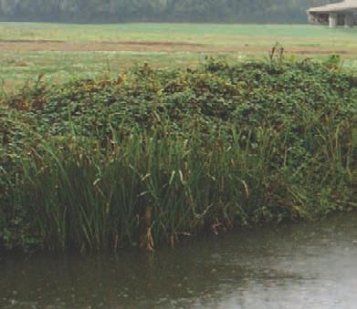
1 B5.2 Open Scenarios: Viaducts As the HS2 line approaches a crossing, it is usually at a height above ground level. In many cases, the most appropriate way to deal with this level difference is with an embankment. This serves to blend the rail in with the landscape, and provide opportunities for planting. However, the visual envelope of the waterway corridor may be open, and there may be many views across the landscape towards places of particular beauty, significance or interest. At these locations, it may be more appropriate to create a viaduct which permits views through the structure, protecting the landscape character of the waterway corridor. Railway Environment In these open scenarios, the piers to either side of the canal corridor significantly impact the waterway environment, and as such they need to become a positive part of it (Fig.B5.7). These Fig.B5.6 - Unresponsive pier arrangement remains a part of the railway environment waterside piers must satisfy a different set of criteria than those used elsewhere. Unlike those in open countryside, these piers will have a close proximity to pedestrians and other waterway users, and must be held to a higher standard. Furthermore, these piers serve to identify the waterway-span within a viaduct, and enhance the relationship between the rail and the water. Waterway Environment Fig.B5.7 - Piers which respond to the canals become a positive part of the waterway environment 24


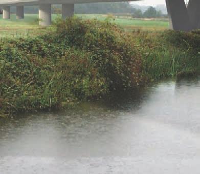

2 Fig.B5.8 - Viaduct structure suits an open scenario 25

 finishes are preferred over vertical concrete abutments (as illustrated in Fig.B5.")
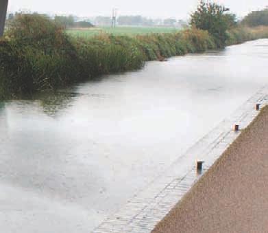
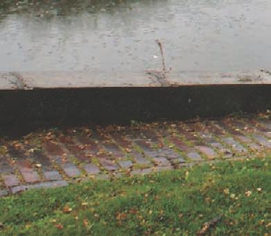
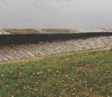
3 Open Scenarios: Embankments Where an embankment solution is selected, the form and position of the abutment is of primary importance Whilst the deck and piers are identifiable as a family of structures within the landscape, the abutment and embankment should read as a part of the landscape itself. It is therefore important that these elements blend comfortably into the landscape, and do not read as obvious manmade intrusions. Sloped abutment walls with natural stone (riprap) finishes are preferred over vertical concrete abutments (as illustrated in Fig.B5.10) The location and orientation of the abutments is also of critical importance, and needs to be Fig.B5.9 - Vertical concrete abutment is an obvious intrusion into the landscape carefully considered in the context of the wider landscape. Bringing the embankment too close to the canal environment essentially creates a focused scenario, in which the other solutions outlined in section 5.1 are more appropriate. In open scenarios it is preferable to stop the embankment (with sloped abutment) at least three spans prior to the main waterway span, in order to maintain views through the structures (as illustrated in Fig.B5.11). Fig.B5.10 -Sloped abutments with tapered riprap blend well into the landscape 26


4 Fig.B Sloped abutment face and multiple back-spans reduces negative visual impact and maintains open views 27


5 B5.3 Maintaining Views As mentioned earlier, a single back-span and pier arrangement (as illustrated in Fig.B5.12) creates an unused dead space which is alien to an historic waterway environment, and is to be avoided. Any positive impact of this open space is usually outweighed by the negative impacts of the poor quality of the space beneath, perception of safety and darkness. In open scenarios, providing a single back-span rarely permits views that would otherwise be obstructed. As such, where views are required, several spans are preferable, as they permit wider views (Fig.B5.13), without creating small, uncomfortable spaces between the waterway environment and the abutments, and associated loss of views. Fig.B Single Back-spans and abutments create unsuitable environments Each location must be assessed on its individual merits, as the clutter of piers associated with viaducts could negatively impact upon the landscape in situations where they are not providing a view through the structure. Where a viaduct is used, longer spans are preferred, as they increase transparency though the structure. By contrast, the multitude of piers associated with short spans tends to obstruct views. Fig.B Multiple spans permit views through 28

6 B6 Waterside Piers As mentioned earlier, in order to read as a positive part of the waterway environment, the waterside piers must address the canal - in orientation, scale, arrangement and form. The relationship between the rail and the water is expressed most clearly through the design of the piers. To that end, it is advisable to create a specific pier design for use when crossing the waterways. Fig.B6.1 and Fig.B6.2 illustrate indicative waterside-pier designs which express some of these characteristics. The subtle and considered expression of the waterside piers must be tailored towards the canal corridor, and would have a number of significant advantages: 1 They identify the significance of the span Fig.B6.1 - Waterway piers should be high-quality and slender 2 They build upon the identity of the waterway, and the relationship to HS2 3 They can be designed to reduce their visual mass as viewed from the towpath 4 They can be detailed at a pedestrian ( 4mph ) scale 5 Surfaces can be detailed so as to not appear too dominant 6 Their design can use light and shadow to reduce their apparent size The viewing distance for the waterside piers will be very close, and as such the quality of their detailing, service integration, colour, and material finish must be suitable for a highquality pedestrian environment. The constraints on pier form are also different for those at the waterway span. The objective must be to create as slender profile as possible when viewed in elevation along the canal. Moreover, opportunities to allow light to penetrate should also be taken. In addition, textures and shadow lines should be utilised to reduce the visual weight of the form, and reduce the scale of the object to that of a pedestrian environment. As the various crossings will be at different heights above the canal, these piers must be designed in a way that is suitable across the range of their potential heights. Fig.B6.2 - Waterway piers should aim to diminish the railway scale a pedestrian one 29
7 B7 Pier Alignment As illustrated in Fig.B7.1, piers that are positioned relative to the rail alignment bear no relationship to the waterway beneath. This creates an unconformable relationship between railand-water, which appears poorly considered. If the alignment of rail above the waterway is skewed (and as such does not bear any formal relationship to the waterway) the supporting piers must address the canal. As per Fig.B7.2, if the piers are aligned to the canal, the composition of the crossing is more comfortable, creating a series of portals for boats to pass through with positive views along the corridor. Aligning the piers to the waterway corridor (rather than the rail) has a positive impact for several Fig.B7.1 - Piers aligned to the rail create dead spaces for skewed crossings reasons: 1 Dead spaces which are unusable, and even unsafe are removed 2 The span is decreased, in turn decreasing structural depth 3 The piers respond visually to the waterway environment (Fig.B7.6) 4 Less structure is visible from along the canal towpath (Fig.B7.4) Fig.B7.2 - Piers aligned to the canal do not create dead spaces for skewed crossings 30


8 Fig.B7.3 - Piers aligned to the rail appear heavy and obtrusive from the towpath Fig.B7.5 - Piers aligned to the rail create dead spaces for skewed crossings Fig.B7.4 - Piers aligned to the canal appear more slender from the towpath Fig.B7.6 - Piers aligned to the canal do not create dead spaces for skewed crossings 31
9 B8 Span Large spans created by skewed alignments and wide foundation footprints in turn create deep structural cross-sections (Fig.B8.1). This depth tends to obscure views, and does not integrate well into the waterway environment. For many crossings, achieving a minimum structural depth will prove to be the priority. In these locations, the shortest possible span will need to be sought. This should primarily be done by ensuring the alignment is as perpendicular as possible, with the piers built as close to the waterway boundary as reasonably achievable and (as mentioned previously), aligned to the water. Moreover, there may be exceptional circumstances in which the foundations may be permitted to encroach upon the waterway s land (Fig.B8.2), subject to agreement and approvals from the Trust, and provided that they remain wholly covered upon completion, and properly detailed into the canal infrastructure. Also to be considered is the minimum widths required for the sustainable use of the waterway corridor. Both the canal and the towpath have minimum widths that must be maintained as defined by the Trust for each individual waterway. Where existing widths are greater than these minimums, the proposed widths must be remain no narrower than existing. 32


10 Fig.B8.1 - Piers aligned to the rail increase spans Fig.B8.3 - Increased spans results in increased structural depths Fig.B8.2 - Piers aligned to the canal reduce spans Fig.B8.4 - Reduced spans results in reduced structural depths 33

. B9.")
11 B9 Abutments Even where abutments are set back from the waterway environment, their significant size will impact upon the appearance of the canals. B9.01 Wing Walls Large areas of concrete read as bright, unnatural surfaces, which do not sit comfortably in rural environments and weather poorly. Wing-walls as illustrated in Fig.B9.1 increase the amount of concrete further, and as such are not acceptable. B9.02 Abutment treatment Sloped abutments with riprap finishes appear as a softer, more natural element in the landscape Fig.B9.1 - Wing-walls create excessive areas of unsightly concrete and are preferred (Fig.B9.2). B9.03 Exposed Concrete Where large areas of exposed concrete are visible from the waterway environment (for example in vertical abutment walls) carefully selected, appropriate textures should be applied in order to break up the surface. Fig.B9.2 - Riprap and textured concrete with sloped embankments blend well into landscapes 34

12 B10 Embankment Edge Often, the raised HS2 line will be viewed against the sky, and as such the clean line of a parapet reads as an obvious and severe intervention into a natural setting (Fig.B10.1). Where an embankment is used, and is visible from the canal, a soft-top edge should be created. This natural green edge should be created by carrying the embankment up to the top edge of the parapet (Fig.B10.2)creating a more natural edge to read against the backdrop of the sky. The slope of the embankment should be shallow enough to ensure that vegetation will naturally grow on its banks, without the need for retaining measures. Fig.B Hard top edge is obvious against the background of the sky Fig.B Soft top edge is blends well into the background of the sky 35


13 B11 Parapets As illustrated in Fig.B11.1, a vertical, flat edge condition creates a large, heavy and dark profile, which tends to exaggerate the already significant depth of the structures. B11.01 Edge By creating a crease, and inclining the upper face of the parapet, as illustrated in Fig.B11.2, the apparent depth is minimised. The inclined face also catches the light, which brightens the surface and further reduces the visual weight of the structure. B11.02 Cantilevers Edge cantilevers are required, which will ensure that the deck spine is cast into shadow, Fig.B Rectilinear edge condition creates heavy appearance reducing apparent depth of the structure. Parapets should also include drip details and other features to ensure that surfaces below are protected from staining. Outer surfaces of parapet string courses should receive a uniform finish that is maintained throughout and is coherent between parapets that are of solid concrete. B11.03 Detailing Parapets should be at a consistent height and appearance over each waterway crossing. Parapet junctions elsewhere should be carefully detailed to ensure a visually smooth transition that is visually integrated with the structure and preserves a uniform edge condition. Fig.B Chamfered edge condition creates slender appearance 36
.")

14 B12 Foundations Detailing of the piers will have a significant impact on the perceived quality of the waterway environment. Details that will not be seen from the railway will be very obvious from the perspective of the canal users. Pile caps and pad foundations should not be visible above ground (Fig.B12.1). Surface finishes should be taken all the way up to the face of the pier or abutment to so that the structure seamlessly touches the ground (Fig.B12.2). Where the pile cap is in close proximity to the canal wall, the design should be developed with the Trust to consider a holistic design linked to the wash wall. Fig.B Visible pile caps are unacceptable All works subject to the Trust s approvals and defined in the side agreement. Fig.B Piers should spring seamlessly from the ground 37


15 B13 Planting Planting will significantly alter the visual impact of HS2. Careful planting can serve to hide, frame and even enhance views of the rail, and can ensure that HS2 sits as comfortably as possible in the wider landscape. B13.01 On-line Planting Whilst the scheme must introduce a well designed arrangement of on-line planting as illustrated in Fig.B13.1, a linear screen of trees may not appear as a natural component of the landscape, and it is likely that this alone will not be sufficient to reduce the negative visual impact upon the waterway environment. Fig.B On-line planting alone is not sufficient B13.02 Strategic Planting Over and above the on-line planting that must be provided, it is essential that additional landscaping and planting is carried out at strategic points along the canal s visual envelope. As Fig.B13.2 shows, carefully designed off-line planting can go a long way to screen and compliment the line of HS2 across the landscape. Even small, well placed copses of trees help to frame views, and focus the eye on the canal, and benefit local biodiversity. Species selection is critical, and must not be simply selected from a generic palette. Local planting strategies must be developed at individual locations, to ensure local appropriateness in terms of habitats and landscape character. Consideration to be given to enhancing the biodiversity of the waterway corridor. Fig.B Strategic off-line planting frames views 38
.")
.")
16 B13.03 Below Deck Planting The width of the HS2 structures will potentially cast the areas below the deck into heavy shadow and prevent natural light and water to penetrate. As a result they prove inhospitable places natural vegetation (Fig.B13.3). Whilst in urban environments hard landscaping is likely to be an appropriate below-deck solution, in rural settings this is unlikely to be the case. Measures to permit natural vegetation to extend as far as possible underneath the crossings should be taken (Fig.B13.4). These measures could range from reducing the deck width, increasing its height, or possibly providing a split deck so as to create a central light well. Allowing vegetation to flourish around the structures helps to maintain the continuity of the natural environment. Fig.B Large areas of abutment appear unsightly Fig.B Permitting natural vegetation to encroach slightly is more suitable 39
. Care must be taken to ensure that these elements are considered as integral components of the crossing s composition.")

17 B14 Railway Furniture Over and above the impact of the structural crossing itself, the additional furniture elements required for the operation of HS2 will greatly affect the visual environment of the waterways (Fig.B14.1). Care must be taken to ensure that these elements are considered as integral components of the crossing s composition. They must appear as coordinated items, so as to minimise their negative visual impact. Simple, elegant design is likely to endure and should not date quickly. B14.01 OLE Gantries Where possible, OLE gantry locations should be coordinated in both symmetry and rhythm Fig.B Uncoordinated OLE is unacceptable with the crossings so as to minimise their negative visual impact on the waterway environment. Aligning the railway furniture (such as the gantries) with the span, ensures that the crossings appear well considered as shown in Fig.B14.2. Where opportunities are available to hide the gantries from the visual envelope of the waterways, (behind vegetation in focused scenarios for example) this would be preferable. The design and colour of this equipment is required to be consistent, and carefully considered so as to minimise its negative visual impact. It will likely be necessary to improve upon current OLE design standards. B14.02 Signage and Signalling Other railway furniture such as signage and signalling should be designed in the same manor; well co-ordinated, minimalist, and where possible located away from waterway crossings. Column mountings should remain inboard of the face of the parapet string course blisters or similar must not be employed on the parapet face. Fig.B Well coordinated OLE appears well considered 40
. The design, materials and appearance of the acoustic barriers must be carefully considered to suit the specific landscape setting.")
 must be designed within a common language to maintain consistency of appearance.")
18 B14.03 Acoustic Barriers Crossings must be dealt with on an individual basis, as in certain areas the negative visual impact of the noise barriers themselves may outweigh the benefits of the reduction in noise which they provide (Fig.B14.3). The design, materials and appearance of the acoustic barriers must be carefully considered to suit the specific landscape setting. Where used, barriers should be carefully designed for robustness, durability and appropriate materials. Acoustic barriers (and any other variant of edge furniture) must be designed within a common language to maintain consistency of appearance. In all cases, it is important that they are designed to suit the particular structure and employ appropriate finishes. B14.04 Security Measures Security measures such as fencing, gates and other items associated with the HS2 line will Fig.B Opaque, coloured acoustic barriers are overly obtrusive have a detrimental impact on the enjoyment of the waterways. It is therefore critical that an appropriate waterside fencing system and arrangement is carefully designed and agreed around each individual waterway crossing. The objective must be to minimise the visual impact of the fencing, by locating it discreetly or by selecting an appropriate waterway fencing solution. B14.05 Other Furniture Poorly located service boxes and other furniture will negatively impact upon the waterway corridor (Fig.B14.4) and should be located neatly, out of sight. Fig.B Service boxes should not be visible from the waterway environment 41
 will significantly affect the perceived quality of the surrounding waterway environment (Fig.B15.1).")

19 B15 Materials Whilst along much of the route, HS2 s material finishes may be hidden from view, where it crosses the waterways the structures will be viewed at a close distance. The quality of the finishes achieved (both initially and over time) will significantly affect the perceived quality of the surrounding waterway environment (Fig.B15.1). The quality of the finishes which fall within the visual envelope of the waterways should be commensurate with that of structures in a high-quality pedestrian environment, rather than that of a rural railway one. B15.01 Concrete Quality Fig.B Poor quality, stained concrete is unacceptable All visible concrete shall be Class F3. This requires that the resulting finish shall be smooth and of uniform texture and appearance (Fig.B15.2). The formwork lining shall leave no stain on the concrete and shall be so joined and fixed to its backing that it imparts no blemishes. It shall be of the same type and obtained from only one source throughout any one structure. The Contractor shall make good any imperfections in the finish. Internal ties and embedded metal parts shall not be used. B15.02 Concrete Colour Patterns and staining from formwork on large areas of exposed concrete should be avoided. Concrete colour should be light grey. Ordinary Portland Cement mixes produce a beige colour that appears unsightly over time. GGBS cements not only provide a considerable reduction in embodied carbon, but also provide a lighter greyer concrete which is more visually appealing, and as such GGBS-based concrete would be a preference. Fig.B Well detailed, uniform concrete creates a high-quality environment 42

. B15.")
20 B15.03 Texture As illustrated in Fig.B15.3, texture may be applied to concrete surfaces. This serves to provide scale and interest, create contrast, and break up large surfaces. B15.04 Structural Steelwork Structural steel should be of a consistent design, and used where appropriate. Excessively large steel structures appear unattractive and are not commensurate with the pedestrian environment of the waterways. Subtle patterns can help to make larger steel sections more appropriate for a high-quality pedestrian environment (Fig.B15.4). B15.05 Steelwork Colour When a painted finish is to be used it should be selected from a palette of colours that is used throughout the project which have been carefully selected to be compatible with each other, as well as the varied environments in which they will be used. One alternative to painted steel Fig.B Textures and shadow gaps mask joints and reduce visual mass of concrete is weathering steel, which offers significant maintenance benefits, as well as producing a finish that blends well with the natural environment (Fig.B15.4). Fig.B Weathering steel can form a positive element of a pedestrian environment 43


21 B16 Detailing Where HS2 crosses the waterways the structures will be viewed at a close distance. The quality of the detailing will impact greatly upon the perceived quality of the surrounding waterway environment. Details which fall within the visual envelope of the waterways should be commensurate with that of structures in a high-quality pedestrian environment, rather than that of a rural railway one. B16.01 Crossheads Visible crossheads over the top of the piers interfere with the visual continuity of the soffit, and clutter the lines of the structure as shown in Fig.B16.1. It is preferred that they are incorporated within the overall depth of the deck. Fig.B Visible crossheads clutter the view of the soffit B16.02 Joints Horizontal construction joints should be avoided, and where possible, piers and columns should be poured full-height. If construction joints are unavoidable, they should be carefully concealed with appropriate detailing. Where movement joints are essential, they should be properly detailed in a similar way, so as to be both carefully concealed, and prevent the passage of moisture. The position of joints and other interfaces should be coordinated between neighbouring elements and generally concealed. B16.03 Soffit A high-quality soffit design is essential in order to make the experience of viewing, or passing underneath the HS2 structures as appealing as possible. Plain, continuous soffits are preferred, designed and constructed as an integral element of the crossing. Fig.B Poorly coordinated elements appear ill-considered and unsightly 44
. B16.")


22 B16.04 Rhythm Where multiple elements (such as piers or joints) are present, their location should be carefully considered so as to achieve a consistent rhythm of elements, poorly co-ordinated elements reduce the apparent quality of the structure (Fig.B16.2). B16.05 Continuity Visual continuity of the structure is very important. The eye should be taken seamlessly along the structure with no interruptions such as protrusions, joints, material inconsistencies or kinks that would interrupt the line. B16.06 Drainage All surface drainage must be dealt with in a closed system that discharges remotely from the structure. If necessary, any below-deck drainage elements such as down-pipes should be located away from pedestrian-facing surfaces, and incorporated smartly into the structures, so Fig.B Poor drainage details impact on the towpath beneath as to minimise their negative visual impact (Fig.B16.4). Concrete should be detailed so that free water does not run down the faces, which would lead to staining. Poorly detailed drainage can also lead to leaking onto the towpath, which creates a dangerous and unattractive environment beneath the crossings (Fig.B16.3). B16.07 Services Integration All cables, ducts and other services must be concealed from public view along the towpath. Services running vertically must be neatly and carefully detailed so as to integrate them within the structures in a discreet and intentional way. Services running horizontally must be entirely hidden from view, and concealed in the soffit with careful detailing. B16.08 Birds and Bats The detailing of all structures must prevent the roosting, perching or nesting of birds or other wildlife. This detailing should be an integral part of the structural design, as opposed to a proprietary roosting-prevention addition, which seldom work, and appear unsightly. Fig.B Poorly designed drainage appears ill-considered and unsightly 45


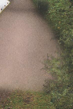
23 B17 Waterway Elements The canals and rivers are well used environments. In addition to the preservation of the waterway s aesthetic, its function must also be protected. The following outlines the practicalities that must be achieved and maintained at HS2 crossings: B17.01 Towpath The towpath must continue uninterrupted beneath the crossings. Where a made towpath exists to either side of the crossing, the surface of the new towpath must match that of the existing area. Where a bridge is to be built over an unmade towpath, formed of earth and natural vegetation, Fig.B Typical towpath makeup this is unlikely to survive. As such a made towpath must be provided (Fig.B17.1). The extent of this towpath should extend to a point to be determined at each crossing. In certain circumstances it may be appropriate for the made towpath to stop immediately at the face of the bridge crossing, yet in other areas obvious tie-in points may be utilised in order to maintain the continuity of the waterway environment. Refer to the Trusts HS2 Technical Appendices. B17.02 Ducting Suitable ducting should be incorporated Into the make-up of the replacement towpath, running along the outer edge of the waterway environment (Fig.B17.1). B17.03 Moorings Where HS2 crosses established moorings, alternative moorings must be provided both during construction and in operation. It is likely that the usage of moorings underneath a high-speed crossing will be negatively impacted, and as such in certain locations it may be appropriate to re-locate the moorings elsewhere. 46
24 In all locations waterways should be treated as a residential environment, as transient boaters may use sites for residential amenity. B17.08 Vandalism Where possible, measures should be taken to reduce the likelyhood of vandalism, and mitigate the damage done if it occours. Concrete sealants and coatings can be used where deemed B17.04 Lighting appropriate in order to aid its removal. Wide, low bridges create unattractive and even unsafe areas beneath them. All HS2 bridges across the waterways are to undergo a lighting assessment in order to determine the most appropriate lighting solution for the area. This may range from no lighting at all (and will likely be the case at most rural crossings) through to controlled lighting systems which ensure a safe B17.09 Maintenance Access HS2 infrastructure will require suitable maintenance and inspection access. This must be carefully integrated into the overall design principles of the crossing structure. and enjoyable pedestrian environment is maintained. Moreover, lighting installations may be appropriate in certain areas, allowing local artists and communities some interaction with the structures. In all circumstances an appropriate maintenance and management strategy is required. B17.05 Time on Site In addition to the leisure uses of the waterways, the canals and rivers also have a residential usage. Construction noise, operation and hours should be controlled in the same way as would be suitable for construction in a residential area. B17.06 Canal Edge Installing a bridge over the canal edge limits the headroom required for future piling rigs and edge-maintainance. All works must be in accordance with the Trust s Third Party Code of Practice. B17.07 Bridge Signage Bridges should be identified to canal users with a plaque or similar. The design of these should be developed with the Trust to identify the structure, date of construction etc. There is an opportunity to link with the use of art in the environment. 47
25 B18 Conclusion This document set out a series of characteristics which must be maintained throughout the waterway environment, and broadly described the quality which the new crossings must achieve. This document establishes basic design principles which apply throughout the waterway network, and does not look at specific crossings. The design, quality, character, alignment and detail of each crossing must be addressed individually, referencing this document alongside the Trust s technical appendices to the side agreement with HS2. 48
26 49
27 50
HS2. Design Principles 1. for Waterway Crossings
 HS2 Design Principles 1 for Waterway Crossings Contents 3 Introduction 38 B13 Planting 5 Purpose of this document 40 B14 Railway Furniture 42 B15 Materials 7 Chapter A What HS2 will affect 44 B16 Detailing
APPENDIX MATAKANA COMMERCIAL URBAN DESIGN GUIDELINES
 APPENDIX MATAKANA COMMERCIAL URBAN DESIGN GUIDELINES 1.0 INTRODUCTION The following urban design guidelines are to be utilised by landowners, planners and other persons involved in development at early
22.15 OUTDOOR ADVERTISING SIGNAGE POLICY
 22.15 OUTDOOR ADVERTISING SIGNAGE POLICY This policy applies to all land where a planning permit is required to construct or display a sign under the provisions of the Kingston Planning Scheme. 22.15-1
General principles for telecommunications development. Mast and site sharing. Installation on existing buildings and structures
 General principles for telecommunications development Mast and site sharing Installation on existing buildings and structures Camouflaging and disguising equipment Using small scale equipment Erecting
5.7.6 St Peters Interchange Portal
 5.7.6 St Peters Interchange Portal Design intent At St Peters interchange the design approach to the tunnel portals differs from that adopted for the western portals at Kingsgrove. An entirely different
Chapter 13 Residential Areas: Appendices APPENDIX 1 Residential Areas
 Chapter 13 Residential Areas: Appendices Page 1 Chapter 13 Residential Areas: Appendices APPENDIX 1 Residential Areas Design Code for Intensive Housing INTRODUCTION DESIGN ELEMENTS A NEIGHBOURHOOD DESIGN
Welcome to this public consultation event for the proposed South Western Relief Road. Thank you for taking the time to come along.
 WELCOME Welcome to this public consultation event for the proposed South Western Relief Road. Thank you for taking the time to come along. The South Western Relief Road (SWRR) route is proposed in Stratford-on-Avon
STILL CREEK CD-1 GUIDELINES (BY-LAW NO. 6654) Adopted by City Council April 24, 1990
 Adopted by City Council April 24, 1990") $2 City of Vancouver Land Use and Development Policies and Guidelines Community Services, 453 W. 12th Ave Vancouver, BC V5Y 1V4 F 604.873.7344 fax 873.7060 planning@city.vancouver.bc.ca STILL CREEK CD-1
$2 City of Vancouver Land Use and Development Policies and Guidelines Community Services, 453 W. 12th Ave Vancouver, BC V5Y 1V4 F 604.873.7344 fax 873.7060 planning@city.vancouver.bc.ca STILL CREEK CD-1
Section C Bridges and retaining walls
 Section C Bridges and retaining walls Above: This existing bridge on SH2 at Tauranga has a simple tapered column form that is a good precedent for the TEL. The open abutment optimises views along the highway
6 BRIDGES. 6.1 Design philosophy. Proposed bridges
 SECTION 6 BRIDGES 6 BRIDGES Throughout the Project, bridges are a key visual element and marker for road users, pedestrians and cyclists. The design of bridges, as with other visible structures, has been
Benches Trash & Recycling Containers Railings and Bullrail Edges Paving Planting Pier Apron Lighting Interpretive Signage
 130 Appendix C: PortWalk The PortWalk give guidance for improvements within the Port s public access and open space system to ensure a certain standard of design consistency while preserving opportunities
CHAPTER 13 DESIGN GUIDELINES
 CHAPTER 13 DESIGN GUIDELINES Section 1300.00 Section 1300.01 Design Guidelines Purpose The purposes of this section are to: A. The purpose of this Section is to establish procedures and standards to serve
Meridian Water Phase 1 Application
 Meridian Water Phase 1 Application MW11 Environmental Statement Non-Technical Summary London Borough of Enfield March 2016 Contents 1 Introduction 1 2 The proposed development 2 3 Evolution of the proposed
Urban and Landscape Design Frameworks Highways and Network Operations Guideline
 Urban and Landscape Design Frameworks Highways and Network Operations Guideline The following outlines the process to be followed through the planning, design and construction phases of a state highway
Housing Development at Balloonagh Tralee Co Kerry
 Design Statement Housing Development at Balloonagh Tralee Co Kerry Area of site 10,400m2 24 houses-12no 3 bed, 12no 2 bed and 4 single bed apartments total residential area of 2411m2 Open space provided
4. INDUSTRIAL 53 CASTLE ROCK DESIGN
 4. INDUSTRIAL 53 CASTLE ROCK DESIGN CASTLE ROCK DESIGN 54 4. INDUSTRIAL Overview Well-designed and attractive industrial centers are the product of blending economic realities with both functional and
Commercial Development Permit Area
 City of Kamloops KAMPLAN Commercial Development Permit Area PURPOSE The purpose of this Development Permit Area (DPA) is to establish objectives and provide guidelines for the form and character of commercial
Canal & River Trust response to the Consultation on the Working Draft Environmental Impact Assessment Report
 High Speed Two Phase 2a: West Midlands to Crewe Response to Working Draft Environmental Impact Assessment Report Please find below the response of the Canal & River Trust. The Trust is the guardian of
CHAPTER ADDITIONAL REQUIREMENTS IN THE NC, NEIGHBORHOOD COMMERCIAL ZONE
 CITY OF MOSES LAKE MUNICIPAL CODE CHAPTER 18.31 ADDITIONAL REQUIREMENTS IN THE NC, NEIGHBORHOOD COMMERCIAL ZONE Sections: 18.31.010 Purpose 18.31.020 Minimum Lot Area 18.31.030 Setbacks 18.31.040 Maximum
8.0 Design and Form of Development 43/
 42/ 8.0 Design and Form of Development 43/ Rothwells Farm, Golborne/ Development Statement Figure 7. Site Constraints Key 44/ Site Boundary 360 Bus Route/Stops Existing Trees Underground Water Pipe Sensitive
13. New Construction. Context & Character
 13. New Construction Context & Character While historic districts convey a sense of time and place which is retained through the preservation of historic buildings and relationships, these areas continue
North York Moors National Park Authority Planning Committee
 Item 8 North York Moors National Park Authority Planning Committee 12 December 2013 Consultation from Redcar and Cleveland Borough Council on proposed Wind Farm at Bank Field Guisborough 1. Purpose of
Nelson Residential Street Frontage Guideline
 DRAFT 22-06-2012 Nelson Residential Street Frontage Guideline June 2012 1317273 Contents and purpose Residential s are important Residential s are much more than corridors which move traffic. Streets allow
Section Three, Appendix 16C Medium Density Housing, Design Assessment Criteria (Residential 8A zone)
") APPENDIX 16C MEDIUM DENSITY HOUSING, DESIGN ASSESSMENT CRITERIA (RESIDENTIAL 8A ZONE) PURPOSE OF APPENDIX 16C (RESIDENTIAL 8A ZONE) In the Residential 8A Zone the following are defined as restricted discretionary
APPENDIX 16C MEDIUM DENSITY HOUSING, DESIGN ASSESSMENT CRITERIA (RESIDENTIAL 8A ZONE) PURPOSE OF APPENDIX 16C (RESIDENTIAL 8A ZONE) In the Residential 8A Zone the following are defined as restricted discretionary
Contents. Annexes. Annex 1 Process Diagram for the discharge of the DCO Requirements. Annex 2 Design Sheet Power Generation Plant
 Design Principles Document December 2014 Contents Summary... 2 Purpose of this Statement... 2 Design Parameters... 2 Guidance Documents... 3 Additional Design Considerations... 3 Public involvement and
DESIGN OF FOOTBRIDGES
 Civil Engineering Technical Requirement CIVIL-SR-006 DESIGN OF FOOTBRIDGES Revision: 9 Updated: 26/08/2015 Queensland Rail 2015 Reproduction by any means (including electronic, mechanical, photocopying,
Section Three, Appendix 17C Multiple Unit Housing Design Assessment Criteria
 APPENDIX 17C MULTIPLE UNIT HOUSING DESIGN ASSESSMENT CRITERIA Purpose of Appendix 17C In the Residential 9 Zone the construction and use of multiple household units located within the Multiple Household
design & access statement Proposed Erection of 68 Bedroom Hotel and Restaurant with Associated Landscaping
 Proposed Erection of 68 Bedroom Hotel and Restaurant with Associated Landscaping Promenade, design & access statement lawrencemcphersonassociates 6 new road, ayr, ka8 8ex On Behalf of July 2015 CONTENTS
Urban Design Manual 2.0 DRIVE-THROUGH FACILITIES. Background. Urban Design Challenges
 222221 2.0 DRIVE-THROUGH FACILITIES Background In recent years, drive-through facilities have grown significantly in popularity with drive-through restaurants, in particular, being established on numerous
Cleveland Innerbelt Bridge / Central Viaduct City Planning Commission November 6, 2009
 Cleveland Innerbelt Bridge / Central Viaduct City Planning Commission November 6, 2009 Process for Aesthetics Subcommittee June 25, 2009 Kick off Meeting June 26, 2009 Gateway and Tremont Focus Groups
ARCHITECTURAL DESIGN REVIEW For submission with development proposals in the City s Tourist Area
 ARCHITECTURAL DESIGN REVIEW For submission with development proposals in the City s Tourist Area Property Owner: Property Address: Architect: Application Number: Date: Please describe in detail how the
Building and Public Space Design Guidelines
 AMERICA'S CUP WYNYARD HOBSON Building and Public Space Design Guidelines INTRODUCTION 10 April 2018 The 36 th America s Cup in Auckland requires the construction of new wharf and breakwater structures.
E16: MAINTENANCE OF LANDSCAPED AREAS
 HIGH SPEED TWO INFORMATION PAPER E16: MAINTENANCE OF LANDSCAPED AREAS This paper outlines the proposed approach to the maintenance of landscaped areas created for HS2 Phase One. It will be of particular
Environmental and Landscape Mapping
 Environmental and Landscape Mapping In support of the Calveley Neighbourhood Plan November 2016 Project Name and Number: Calveley Neighbourhood Plan 16-025 Document Name and Revision: Environmental and
SEABANK 3. Interim Landscape and Design Statement
 SEABANK 3 Interim Landscape and Design Statement Prepared for: SSE plc URS Infrastructure & Environment UK Limited. Scott House Alencon Link Basingstoke Hampshire RG21 7PP UK 1 TABLE OF CONTENTS 1 INTRODUCTION...
4. MASTERPLAN FRAMEWORK
 6a 6b 4. MASTERPLAN FRAMEWORK 6. Car Parks 6c Car Parks 6a and 6b will provide permanent parking. Area 6a will serve the foodstore with tarmac surfacing within a defined area to the west of the adjacent
Marinas, Mooring and Boating Facilities 23
 195 Marinas, Moorings and Waterfronts 23.1 The valleys of the River Severn, River Avon, River Teme and their tributaries significantly define the natural character of South Worcestershire, whilst the canal
VILLAGE OF SKOKIE Design Guidelines for Mixed-Use Districts NX Neighborhood Mixed-Use TX Transit Mixed-Use CX Core Mixed-Use
 VILLAGE OF SKOKIE Design Guidelines for Mixed-Use Districts NX Neighborhood Mixed-Use TX Transit Mixed-Use CX Core Mixed-Use TABLE OF CONTENTS CHAPTER 1 SITE DESIGN Purpose 1 CHAPTER 2 SITE DESIGN Streetscape
Character Area 1: Town Core
 Character Area 1: Town Core Map S 354 Copyright Cotswold District Council 109 Character Area 1: Town Core Key Characteristics 355 356 357 358 359 360 361 362 363 364 365 366 367 368 369 370 Copyright Cotswold
Multi family Residential Development Permit Area
 City of Kamloops KAMPLAN Multi family Residential Development Permit Area PURPOSE The purpose of this Development Permit Area (DPA) is to establish objectives and provide guidelines for the form and character
WELCOME TO PUBLIC INFORMATION CENTRE #2. Please Sign In
 WELCOME TO PUBLIC INFORMATION CENTRE #2 Replacement of Oxtongue Lake Narrows Bridge & Oxtongue River Bridge, Highway 60 (G.W.P. 93-89-00 & G.W.P. 5550-04-00) Class Environmental Assessment (Group B) Please
Reference: 15/06961/RCU Received: 13th November 2015 Accepted: 17th November 2015 Ward: Coppetts Expiry 12th January 2016
 Location 91 Manor Drive London N20 0XD Reference: 15/06961/RCU Received: 13th November 2015 Accepted: 17th November 2015 Ward: Coppetts Expiry 12th January 2016 Applicant: Mr Christos Papadopoulos Proposal:
Newcourt Masterplan. November Exeter Local Development Framework
 Newcourt Masterplan November 2010 Exeter Local Development Framework Background The Exeter Core Strategy Proposed Submission sets out the vision, objectives and strategy for the development of Exeter up
PLANNING COMMITTEE DATE: 07/09/2015 REPORT OF THE SENIOR MANAGER PLANNING AND ENVIRONMENT SERVICE CAERNARFON. Number: 4
 Number: 4 Application Number: C15/0034/37/LL Date Registered: 21/05/2015 Application Type: Full - Planning Community: Llanaelhaearn Ward: Llanaelhaearn Proposal: Location: Summary of the Recommendation:
CHAPTER 6 DESIGN GUIDELINES FOR INDIVIDUAL BUILDING ELEMENTS. Commercial Facades
 Design Guidelines for Historic Resources CHAPTER 6 DESIGN GUIDELINES FOR INDIVIDUAL BUILDING ELEMENTS This chapter presents design guidelines for the preservation of individual historic building elements
Wind energy development in the South Pennines landscape
 Wind energy development in the South Pennines landscape Programme for today Background Policy context South Pennines landscape Impacts of wind energy development The South Pennines Wind Energy Landscape
SECTION ONE North East Industrial Zone Design Guide Palmerston North City Council June 2004
 SECTION ONE North East Industrial Zone Design Guide Palmerston North City Council June 2004 young heart easy living 1 Preface Industrial areas are a very important component of the economic well-being
an Inspector appointed by the Secretary of State for Communities and Local Government
 Appeal Decision Site visit made on 6 November 2017 by Rachel Walmsley BSc MSc MA MRTPI an Inspector appointed by the Secretary of State for Communities and Local Government Decision date: 19 th January
DUNSFOLD NEIGHBOURHOOD PLAN Site Selection Policies
 DUNSFOLD NEIGHBOURHOOD PLAN Site Selection Policies The criteria for assessing sites for future housing and business development in Dunsfold are set out below. (Development criteria, covering what it is
Neighbourhood Planning Local Green Spaces
 Neighbourhood Planning Local Green Spaces Introduction... 2 1. Why green space is important... 4 2. Neighbourhood plans and green space... 6 3. Evidence... 8 Statutory designations... 9 Green space audit...
Oxford Green Belt Study. Summary of Final Report Prepared by LUC October 2015
 Oxford Green Belt Study Summary of Final Report Prepared by LUC October 2015 Project Title: Oxford Green Belt Study Client: Oxfordshire County Council Version Date Version Details Prepared by Checked by
ENVIRONMENTAL AND LANDSCAPE MAPPING
 APPENDIX IV : Environmental and Landscape Mapping ENVIRONMENTAL AND LANDSCAPE MAPPING Calveley Neighbourhood Plan November 2016 ENVIRONMENTAL AND LANDSCAPE MAPPING Calveley Neighbourhood Plan Calveley
RIVERSIDE DESIGN CD-1 GUIDELINES. Adopted by City Council August 9, 1983
 $1 City of Vancouver Land Use and Development Policies and Guidelines Community Services, 453 W. 12th Ave Vancouver, BC V5Y 1V4 F 604.873.7344 fax 873.7060 planning@city.vancouver.bc.ca RIVERSIDE DESIGN
Suffolk Coastal Local Plan Review Issues and Options, August 2017, Public Consultation
 Suffolk Coastal Local Plan Review Issues and Options, August 2017, Public Consultation Having reviewed the issues and options documents, the Society has made the following response: Part 1 - Strategic
TALL BUILDING GUIDELINES
 TALL BUILDING GUIDELINES Urban Design Guidance for the Site Planning and Design of Tall Buildings in Milton May, 2018 A Place of Possibility Contents 1.0 INTRODUCTION 1 1.1 What is a Tall Building? 2
Statement of Community Involvement LAND OFF SOUTHDOWN ROAD HORNDEAN, HAMPSHIRE
 LAND OFF SOUTHDOWN ROAD HORNDEAN, HAMPSHIRE CONTENTS Page 1. Introduction 3 2. Pre-application Discussions 4 3. The Consultation Process 5 4. Consultation Feedback 7 5. Responses to Consultation Feedback
Streetscape Patterns. Design Guidelines, Ridgewood Village Center Historic District, Ridgewood, N.J. page 20
 North Broad Street has a unique streetscape pattern with broad curving street, tight enclosure on the east side with attached commercial buildings aligned with the sidewalk, and landscaped open space on
Future Five. Design/ Development Guidelines. January 2008 Amended June 08 per City Council motion
 Future Five Design/ Development Guidelines January 2008 Amended June 08 per City Council motion 5-Points Design Guidelines Table of Contents I. Introduction 3 II. Area boundaries 4 III. Review Process
Assessment of Landscape, Visual and Natural Character Effects
 Assessment of Landscape, Visual and Natural Character Effects Consent Footprint Amendments Mangamaunu Half Moon Bay Okiwi Bay South Report prepared for: New Zealand Transport Agency and KiwiRail Holdings
10 Proposed Redevelopment, Tewkesbury Road, Cheltenham SCHEME EVOLUTION STARBUCKS
 SCHEME EVOLUTION STARBUCKS The proposed Starbucks Drive Thru alongside the proposed food store provides an appropriate mix of uses, suitable for this location. The proposed store is bespoke, designed specifically
B - Coalfield River Corridor Landscape Character Type
 B - Coalfield River Corridor Landscape Character Type Landscape Character Type - Coalfield River Corridor The Coalfield River Corridors Landscape Character Type is located in the two converging valleys
SUBCHAPTER 4-B GUIDELINES FOR THE B-3 COMMERCIAL CHARACTER AREA
 1 SUBCHAPTER 4-B GUIDELINES FOR THE B-3 COMMERCIAL CHARACTER AREA Downtown Bozeman should be the location of buildings of greatest height and intensity in the community. The following guidelines apply
Principles of Landscaping
 Principles of Landscaping 1. Definition of Landscaping Landscaping is a branch of horticulture and is an important field in which architecture, art and knowledge are combined to achieve beauty and utility.
WELCOME TO THE PUBLIC INFORMATION CENTRE. Please Sign In
 WELCOME TO THE PUBLIC INFORMATION CENTRE Replacement of Oxtongue Lake Narrows Bridge & Oxtongue River Bridge, Highway 60 (G.W.P. 93-89-00 & G.W.P. 5550-04-00) Class Environmental Assessment (Group B) Please
ROAD AND CAR PARK DESIGN GUIDELINES
 3.2 ROAD AND CAR PARK DESIGN GUIDELINES PIHA AREA DESIGN GUIDELINES AUCKLAND REGIONAL COUNCIL 37 Existing Road and Car Park Photos: North Piha carpark Anawhata carpark Winstone Track carpark off Piha Road
LEEDS SITE ALLOCATIONS PLAN MATTER 3 GREEN BELT KCS DEVELOPMENT AUGUST 2017
 LEEDS SITE ALLOCATIONS PLAN MATTER 3 GREEN BELT KCS DEVELOPMENT AUGUST 2017 Smith Limited Suite 9C Joseph s Well Hanover Walk Leeds LS3 1AB T: 0113 2431919 F: 0113 2422198 E: planning@peacockandsmith.co.uk
WELLINGTON HOSPITAL DESIGN GUIDE TABLE OF CONTENTS
 WELLINGTON HOSPITAL DESIGN GUIDE TABLE OF CONTENTS 1.0 Introduction Page 2 The Place of Wellington Hospital 2 The Future of the Hospital 2 2.0 The Intention of the Design Guide 3 3.0 Analysis 4 General
Design Guidelines for Commercial Development
 Design Guidelines for Commercial Development Development Services 972-466-3225 cityofcarrollton.com Table of Contents Purpose...1 Design Objectives...2 Intent...3 Building Design Guidelines...4 Materials...5
ARCHITECTURAL ANALYSIS
 ARCHITECTURAL ANALYSIS YR12 GRAPHICS WHANGAREI GIRLS HIGH SCHOOL INFORMATION TO HELP WITH DESIGN PROCESS, NOTATIONS, & DESIGN HISTORY ARCHITECTURAL ANALYSIS When we analyse a building, we begin by scanning
PART 05 VISUAL SETTING
 PART 05 VISUAL SETTING 5.1 How to use the Visual Settings 5.2 Views from the Headland 5.3 Creek Foreshore Park Looking North 5.4 Bridge looking North 5.5 Bridge looking West 5.6 Bridge looking South 5.7
Views from the Bridge
 Chapter 2 Views from the Bridge Alternative 2A would primarily have adverse visual impacts to views from the Bridge, with the exception of a strongly adverse visual impact from Viewpoint 11 (Car View East)
SECTION TWO: Overall Design Guidelines
 SECTION TWO: Overall Design Guidelines This section provides overall design principles and guidelines for the Gardnerville Mixed-use Overlay. They provide criteria for mixed-use places consisting of residential,
Design Review Report Llanfoist to Abergavenny Footbridge DCFW Ref: 118 Meeting of 10th August 2016
 Design Review Report Llanfoist to Abergavenny Footbridge DCFW Ref: 118 Meeting of 10 th August 2016 Declarations of Interest Panel members, observers and other relevant parties are required to declare
Overview Report. Proposed Development
 Overview Report Proposed Development the construction of a 1km cycle/pedestrian trail including a new footbridge, new car park and entrance road at Drumshanbo Lock and a new pedestrian/cycle road crossing,
CHAPTER FOUR: Alternatives to the Proposed Action
 CHAPTER FOUR: Alternatives to the Proposed Action CHAPTER FOUR: ALTERNATIVES TO THE PROPOSED ACTION 4.1 Alternatives to the West Campus Plan The following sections discuss alternatives to the proposed
Design of Movable Bridges - selected examples
 Design of Movable Bridges - selected examples Adriaan Kok Designer, Project Manager ipv Delft Delft, The Netherlands adriaankok@ipvdelft.nl Niels Degenkamp Designer, Project Manager ipv Delft Delft, The
BRE Strategic Ecological Framework LI Technical Information Note 03/2016
 BRE Strategic Ecological Framework Technical Information Note 03/2016 September 2016 Contents 1. Introduction 2. Aims of BRE s Strategic Ecological Framework 3. How SEF is different from previous approaches
Chapter 5 Urban Design and Public Realm
 5.1 Introduction Public realm is all areas of the urban fabric to which the public have access. It is where physical interaction takes place between people. It therefore, includes buildings and their design,
EXTRACT FROM THE CUDDINGTON NEIGHBOURHOOD PLAN The Policies
 EXTRACT FROM THE CUDDINGTON NEIGHBOURHOOD PLAN The Policies Environment and Landscape Policy 1 - Landscape Setting Development should respect and wherever possible enhance the landscape setting of Cuddington
Loss Prevention Standards
 Introduction Fire compartmentation is an essential part of an effective fire safety design of a building. The primary objective of fire compartmentation or passive fire protection is to prevent a building
NON-TECHNICAL SUMMARY
 NON-TECHNICAL SUMMARY THE HIDE, BISHOP AUCKLAND PROPOSED ECO CHALET DEVELOPMENT NON-TECHNICAL SUMMARY 1 Introduction 1.1.1 This non-technical summary for the (ES) prepared in relation to the proposed eco-chalet
97 Lea Bridge Road, Leyton, E10 7QL London Borough of Waltham Forest December 2015
 97 Lea Bridge Road, Leyton, E10 7QL London Borough of Waltham Forest December 2015 Public Realm and Landscape Proposals LEA BRIDGE ROAD, WALTHAMSTOW Public Realm & Landscape Proposals BDP(90)RPT001 December
an Inspector appointed by the Secretary of State for Communities and Local Government
 Appeal Decision Site visit made on 22 April 2014 by Simon Warder MA BSc(Hons) DipUD(Dist) MRTPI an Inspector appointed by the Secretary of State for Communities and Local Government Decision date: 28 May
4 RESIDENTIAL ZONE. 4.1 Background
 4 RESIDENTIAL ZONE 4.1 Background The residential areas within the City are characterised by mainly lowrise dwellings sited on individual allotments. Past architectural styles, settlement patterns and
Chapter 14. Aesthetic Considerations in Transportation Systems Evaluation
 466 Chapter 14 Aesthetic Considerations in Transportation Systems Evaluation 467 Topics: Transportation Project Types that Typically Affect Aesthetic Quality, Topological Features of Transportation Systems
GREENBANK DEVELOPMENT MASTERPLAN
 DEVELOPMENT MASTERPLAN POTENTIAL TRAIN STATION COMMUNITY CENTRE Greenbank will be a connected masterplanned community providing easy access to local and surrounding amenity. Affordable quality homes, green
INNERBELT BRIDGE PUBLIC MEETING #2
 Welcome to the INNERBELT BRIDGE PUBLIC MEETING #2 Today s Discussion Welcome and Introductions (Bob Brown, City of Cleveland) Innerbelt Project Status (Craig Hebebrand, ODOT) Bridge Type Selection Update
Memorial Business Park Site. Proposed Future Development. Design guidelines. August
 Memorial Business Park Site Proposed Future Development Design guidelines August 2014 www.designenvironment.co.nz 0064 3 358 3040 Contents 1.0 Background 1.1 Introduction 3 1.2 Objectives 4 2.0 Context
Cotswolds AONB Landscape Strategy and Guidelines. June 2016
 Cotswolds AONB Landscape Strategy and Guidelines June 2016 Cotswolds AONB Landscape Strategy and Guidelines Introduction The evolution of the landscape of the Cotswolds AONB is a result of the interaction
Section 6A 6A Purpose of the Natural Features and Landscapes Provisions
 Section 6A 6A Purpose of the Natural Features and Landscapes Provisions This Chapter addresses the protection and management of natural features and landscapes within the City. The City has a number of
Wide asphalt driveway abutting school property. garage built with incompatible materials, too close to park. incompatible fencing materials
 Wide asphalt driveway abutting school property incompatible fencing materials garage built with incompatible materials, too close to park Lack of plantings as a buffer between private property and open
STATEMENT OF OBJECTION TO THE PROPOSED DEVELOPMENT OF LAND AT CHURCH CLIFF DRIVE FILEY
 STATEMENT OF OBJECTION TO THE PROPOSED DEVELOPMENT OF LAND AT CHURCH CLIFF DRIVE FILEY You will be aware that Scarborough borough council have adopted a new local plan that includes land at Church Cliff
Ipswich Issues and Options for the Ipswich Local Plan Review, August 2017, Public Consultation
 Ipswich Issues and Options for the Ipswich Local Plan Review, August 2017, Public Consultation Having reviewed the issues and options documents, the Society has made the following response: Part 1 Strategic
4.3 Dudley Area Plan. Introduction. History and Existing Character. Desired Future Character for Dudley
 4.3 Dudley Area Plan Introduction The suburb of Dudley has developed as a result of various circumstances including its topography, history and mineral resources. Dudley development has been identified
Industrial Development Permit Area
 Industrial Development Permit Area PURPOSE The purpose of this Development Permit Area (DPA) is to establish objectives and provide guidelines for the form and character of industrial development in the
FRASER LANDS CD-1 GUIDELINES (BLOCKS 68 AND 69) Adopted by City Council April 1989
 Adopted by City Council April 1989") $1 City of Vancouver Land Use and Development Policies and Guidelines Community Services, 453 W. 12th Ave Vancouver, BC V5Y 1V4 F 604.873.7344 fax 873.7060 planning@city.vancouver.bc.ca FRASER LANDS CD-1
$1 City of Vancouver Land Use and Development Policies and Guidelines Community Services, 453 W. 12th Ave Vancouver, BC V5Y 1V4 F 604.873.7344 fax 873.7060 planning@city.vancouver.bc.ca FRASER LANDS CD-1
AIRPORT BUSINESS PARK
 PIER MAC PETROLEUM INSTALLATION LTD. AIRPORT BUSINESS PARK DEVELOPMENT APPLICATIONS March 2003 4.1 Airport Business Park Development Permit Area 4.1.1 Justification/Design Concept The design concept envisioned
Beckett Bridge Replacement (Design) Riverside Drive from west of Chesapeake Drive to Pampas Avenue
 Riverside Drive from west of Chesapeake Drive to Pampas Avenue") Pinellas County Public Works Traffic & Roadway Division Transportation Engineering Section Replacement (Design) Riverside Drive from west of Chesapeake Drive to Pampas Avenue Agenda - Aesthetics Committee
Pinellas County Public Works Traffic & Roadway Division Transportation Engineering Section Replacement (Design) Riverside Drive from west of Chesapeake Drive to Pampas Avenue Agenda - Aesthetics Committee
VILLAGE OF CHANNAHON COMMERCIAL DESIGN GUIDELINES. Village of Channahon S. Navajo Drive Channahon, IL (815)
") VILLAGE OF CHANNAHON COMMERCIAL DESIGN GUIDELINES Village of Channahon 24555 S. Navajo Drive Channahon, IL 60410 (815) 467-6644 www.channahon.org Adopted March 6, 2006 VILLAGE OF CHANNAHON COMMERCIAL DESIGN
VILLAGE OF CHANNAHON COMMERCIAL DESIGN GUIDELINES Village of Channahon 24555 S. Navajo Drive Channahon, IL 60410 (815) 467-6644 www.channahon.org Adopted March 6, 2006 VILLAGE OF CHANNAHON COMMERCIAL DESIGN
LITTLETON CENTER DESIGN GUIDELINES
 LITTLETON CENTER DESIGN GUIDELINES Littleton Center Design Guidelines 1 I. DESIGN REVIEW PROCESS These Design Guidelines have been initially created by Hallin Family LLC (the "Developer"), and govern all