User Instructions Ultra Low Temperature Freezers Model LAB/ULT
|
|
|
- Sibyl Watkins
- 6 years ago
- Views:
Transcription
1


2 Elcold Frysere Hobro ApS Løgstørvej 81 Hørby 95 Hobro Denmark Phone Fax i.c. graphics cph


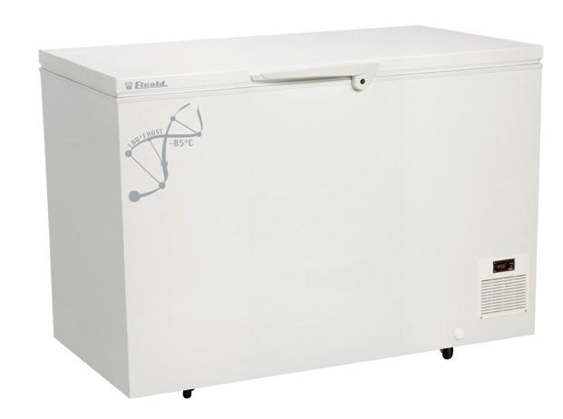
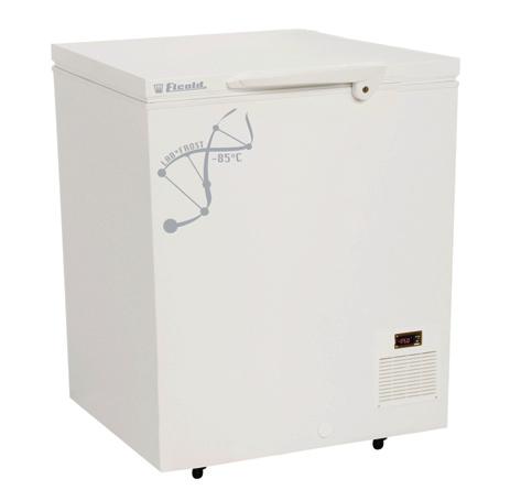
3 User Instructions Lab* Frost Ultra Low Temperature Freezers Model LAB/ULT


4 SAFETY INFORMATIONS The LAB/ULT freezers contains environmentally friendly but flammable refigerants. It means danger of explosion if for any reason the refigerants are allowed to escape from the system. The refigeration system must never be accessed by unauthorized personal. When transporting and installing the unit, ensure that no part of the tubing system is damaged. If the tubing is damaged and leak occurs, avoid any ignition sources and naked flames near the unit, and ventilate the room immediately. In order to avoid formation of flammable gas/air mixtures an case of a leak from the refigeration system, the room where the unit is placed must have a volume of minimum 4 m3 corresponding to a surface area of approx. 4 m2 in a room with normal ceiling height. WARNING!!! The ventilation openings must never be covered or blocked. Never use a stream or water cleaning device during cleaning or defrosting on order to avoid short circuits in the electrical system. Do not place any electrical devices in the freezer. Products containing flammable gasses and explosives must not be stored in the freezer. 2
5 USER INSTRUCTIONS Congratulations on your new low temperature freezer. We trust that it will serve you for many years to come. In order to gain optimum benefit from your freezer, please read the following instructions thoroughly and act accordingly. The low-temperature freezers are used for freezing and long-term storing of food products, medical preparations ( vaccines, blood plasm, ect.) and other biological products. 1. Environmental protection and disposal. The packaging is designed to protect the appliance and its components during transportation, and it is made of recyclable materials. Please return the packaging to an official collection point for recycling. Old appliances contain reusable materials and should not be disposed of together with household refuse. Remove the spring-action hinges from the appliance, in order to prevent children from being entrapped in the appliance. Ensure that no part of the refrigeration tubing is damaged as the refrigerant in the appliance risks escaping to the environment. Information about refrigerant type and amount will be found on the type plate on the rear of the appliance (Fig. 1). 2. Safety instructions. In order to prevent injuries and or damage to the appliance, it should be unpacked and set up by min. two people. If upon unpacking the appliance is found damaged, do not connect to the mains, but contact the supplier. Interference with or repair to the appliance should only be carried out by authorized personnel, in order to avoid any injuries. (contact the supplier for further information). Never put naked flames or other ignition sources inside the appliance. GB Never touch the freezers interior or products in the freezer when the freezer is operating. Use gloves or alike in order to avoid injuries (frost-bite). Keep the key to the appliance away from the appliance and out of the reach of children. 3. IMPORTANT NOTE!!! The type of refrigerant in the 85 C freezers, is a mixture of different flammable hydrocarbons. These freezers are designed and tested according to the EN 378 standard, under clause A3 room and L3 refrigerants, this means that the volume of the room where the freezers is placed must have a volume of minimum 4m 3 corresponding to approx. 4m 2 in a room with a normal floor height. 4. Connection to the mains. For safety reasons the appliance must be earthed. If you are in any doubt, please contact an authorized electri cian. The appliance should be left for 5 hours before it is connected to the mains. If the appliance is connected before that, there is a risk of damaging the compressor. If for any reason the appliance is disconnected from the mains, please wait 1 minutes before re-connecting. The electronic starting device needs this time to cool down, before a safe re-start can be made. 5. Before use. Before use, the interior of the appliance should be cleaned with a mild soap solution, and wiped off with a dry clean cloth. Never use any kind of solvent or other chemicals. 3

 in order to allow the heat from the compressor motor to dissipate.")

6 6. Setting up the freezer. The freezer should not be placed where it might be splashed with water, in extreme high humidity or in direct sunlight. Any of these factors may lead to a reduction in performance and shorten the life span of the components. The freezer should be placed on a horizontal level, and should not be placed close to a heating appliance or heating tubes. Allow a minimum of 5mm (2 ) clearance on the side and the back. The side with the ventilation grill should have a clearance of at least 1 mm (4 ) in order to allow the heat from the compressor motor to dissipate. Underneath the appliance there should be a gap of 15 mm approx. (1 2 ). On a soft surface, e.g. carpet, it may be necessary to ensure the correct distance by means of spacers. 7. Electrical supply. The electrical supply should always be in accordance with the rating plate on the back of the freezer. The supply must always be in accordance with the law and regulations regarding electrical safety, if any doubts contact your supplier. there is an electricity supply to the plug or if the fuse is blown. If not please go to trouble shooting page Operating the freezer The empty freezer should be switched on for at least 5-6 hours prior to loading of the freezer. The freezer should not be loaded above the inside walls which is also the load line limit. Please note: After the lid has been opened, there will be a vacuum created inside the freezer due to the low temperatures. Wait a few minutes before trying to reopen the lid otherwise the handle could be damaged. 1.Defrosting. In order for the freezer to work to its maximum efficiency the cabinet should be defrosted when a approx. 2mm thick ice layer has formed inside the cabinet. The ice layer is easily removed with a plastic or wooden scraper. Never use a sharp metal object which might will cause damage to the inner liner. The defrosting frequency is determined mainly by two factors the usage pattern (number of lid openings) and the relative humidity. Excess water can be drained out by using the drain water outlet on the front of the freezer. Fig Starting Up. In case the compressor does not start when the freezer has been plugged in, the electrical supply may not be in order. Check if 11.Cleaning. Cleaning should be done when needed. When used in a dirty environment it might be necessary to remove the compressor compartment grill, and clean the compressor compartment eventually with a vacuum cleaner. If the cleaning process is neglected there is a risk that the performance of the freezer will be effected, and even damage to the 4


7 compressor could occur due to overheating. 12. Storage. If the freezer is stored for a period of time, the lid should be kept open for free circulation of air inside the cabinet in order to avoid corrosion of the inner liner. 13. Temperature control LAB/ULT- freezers. The temperature inside the freezer is controlled by the electronic controller in the front grill. The controller has a digital readout of the temperature inside the cabinet. and the option of changing the temperature inside the cabinet. 14. External voltage and temperature alarm. Optionally the freezer can be equipped with a battery operated alarm box with connections for external alarm for voltage failure and temperature alarm. The battery should be exchanged every two years. Please note! When commissioning the freezer, the battery must be turned into its correct position. More details on page Dixell controller. 16. Functions. How to see the set point: 1.Press and immediately release the SET key, the display will now show the set point value. 2.Press and immediately release the SET key or wait for 5 seconds to display the probe value again. How to lock and unlock the keyboard 1.Press the up and down keys simultaneously for more than 3.seconds. How to change the set point 1.Press the SET key for more than 3.seconds to change the set point value. 2.The set point value will be displayed and the LED starts flashing. 3.To change the set point value, push the up or down arrow. 4. To memorise the new setting press the SET key again or wait 15 seconds for the controller to return to normal display of the probe temperature. 17. Setting the controllers offset value The LAB/ULT freezer is designed for long time and safe storage of sensitive products. In some situations the LAB/ULT freezer is also used for other applications like in laboratories for different low temperature test. Depending on the actual situation it might be necessary to change the controllers offset value in order to get a correspondence between the reading on the display and the actual temperature inside the cabinet. The factory setting is an offset of 2 dgr:c. The offset can be adjusted in the following way. Unlock the keyboard. Enter the programming mode by pressing the SET and arrow down keys for 3 seconds. Select the parameter Opb by pressing arrow up or down key. Press the SET key to display its value. Use arrow up or down to change its value. The offset can be adjusted to +/- 12 dgr.c Press SET to store the new value. Press SET + arrow up or wait 15 seconds without pressing any key. The new value will now be stored. For more detailed information about programming the Dixell controllers please consult the attached manuals. 5

8 18. Trouble shooting. The appliance is not operating. Please check: Is the electrical plug connected to the mains (wall socket)? Has the fuse blown? The temperature inside the appliance is too high. Please check: Is the Dixell controller set to the correct temperature? Has an excess amount of ice formed inside the appliance? The appliance is operating continuously. Please check: Is the ambient temperature very high? Has the appliance recently been loaded with a large amount of warm products? If you have checked the above points and the appliance is still not working as expected, please contact your local dealer for further advice. 19. LN 2 or LCO 2 back-up On the rear side of the cabinet there is a label and a marking, where it is possible to insert either a temperature probe or a backup LN2 or LCO2 supply. The inner and outer skins are pre-drilled. IMPORTANT NOTE!!! Do not attempt to drill or in other way make access to the freezers interior other places than at the marking, there is a risk of damaging the freezers tubing system, resulting in a leakage with inflammable gasses. Back-up inlet 6

9 DIXELL XT111C FOR LAB/ULT MODELS XT111C Single Stage Digital Controller For Temperature GENERAL WARNING Please read before using this manual This manual is part of the product and should be kept near the instrument for easy and quick reference. The instrument shall not be used for purposes different from those de scribed hereunder. It cannot be used as a safety device. Check the application limits before proceeding. Safety Precautions Check the supply voltage is correct before connecting the instrument. Do not expose to water or moisture: use the controller only within the operating limits avoiding sudden temperature changes with high atmospheric humidity to prevent formation of condensation Warning: disconnect all electrical connections before any kind of maintenance The instrument must not be opened. In case of failure or faulty operation send the instrument back to the distributor with a detailed description of the fault. Consider the maximum current which can be applied to each relay (see Technical Data). Ensure that the wires for probes, loads and the power supply are separated and far enough from each other, without crossing or intertwining. In case of applications in industrial environments, the use of mains filters (our mod. FT1) in parallel with inductive loads could be useful. GENERAL DESCRIPTION The XT11C and XT111C are single-stage ON/OFF controllers for temperature, humidity and pressure applications with direct or inverse action, user-selectable. The analogue input type can be set by parameter between the following, according to the model: - PTC, NTC; - PTC, NTC, Pt1, Thermocouple J, K, S; - 4 2mA, 1V, 1V. FIRST INSTALLATION Probe setting The pre-set probe type is written on the label of the instrument, see picture. If it is different from theprobe that has be used, set the probe following procedure below How to set the probe. 1. Enter the programming menu by pressing the SET+ n for 3s. 2. Select the Pbc (Probe configuration) parameter and push the SET key. 3. Set the kind of probe: a. Controller for temperature: Pt= Pt1, J = J thermocouple, c = K thermocouple, S = S thermocouple; Ptc = PTC; ntc = ntc b. Controller with current or voltage inputs: cur=4 2mA, - 1= 1V, 1= 1V 4. Push the SET key to confirm it. 5. Switch the controller off and on again NOTE: Before proceeding check and, if necessary; set with appropriate values the Minimum Set Points (LS1 e LS2) and Maximum Set Points (US1 e US2). See also the paragraphs concerning the programming. 7
, by pressing the SET key for more than 4s the controller is switched OFF. To switch the instrument on again press the SET key.")


 Energy saving activated by digital input - ALARM signal - In indicates the parameter is also present in Pr1 TO see THE SETPOINT SET 1.")
10 Front panel commands SET: To display and modify target set point; in programming mode it selects a parameter or confirm an operation. TO SWITCH THE INSTRUMENT ON/OFF: If the function is enabled (par. onf=yes), by pressing the SET key for more than 4s the controller is switched OFF. To switch the instrument on again press the SET key. o UP: in programming mode it browses the parameter codes or increases the displayed value. Hold it pressed for a faster change n DOWN: in programming mode it browses the parameter codes or decreases the displayed value. Hold it pressed for a faster change KEY COMBINATIONS: o + n To lock & unlock the keyboard. SET + n To enter in programming mode. SET + o To return to the room temperature display. Use of LEDS A series of light points on the front panels is used to monitor the loads controlled by the instrument. Each LED function is described in the following table. LED MOD FUNCTION E LED 1 ON flashing Output relay enabled - Programming Phase (flashing with LED2) LED 2 E.S. flashing ON ON - Programming Phase (flashing with LED1) Energy saving activated by digital input - ALARM signal - In indicates the parameter is also present in Pr1 TO see THE SETPOINT SET 1. Push and release the SET key to see the Set point value; 2. To come back to the normal display push again the SET key or wait 1s. TO CHANGE THE SETPOINT SET 1. Hold pushed the SET key for 3s to change the Set point value; 2. The value of the set point will be displayed and the LED1 & 2 start blinking; 3. To change the Set value push the o or n arrows within 1s. 4. To memorise the new set point value push the SET key again or wait 1 s. TO enter the parameters list Pr1 To enter the parameter list Pr1 (user accessible parameters) operate as follows: 1. Push for 3s the SET + n keys (LED1 & 2 start blinking). SET 2. The controller will display the first parameter present in the Pr1 menu.. TO ENTER the parameters list The parameter list contains the configuration parameters. A security code is required to enter it. 1. Enter the Pr1 level, see above paragraph. 2. Select parameter and press the SET key. 3. The PAS flashing message is displayed, shortly followed by - - with a flashing zero. 4. Use o or n to input the security code in the flashing digit; con firm the figure by pressing SET. The security code is If the security code is correct the access to is enabled by pressing SET on the last digit. 8

11 Another possibility is the following: After switching ON the instrument, within 3 seconds, push SET + n keys together for 3s: the menu will be entered. HOW TO MOVE A PARAMETER FROM THE PR2 MENU TO PR1 AND VICEVERSA. Each parameter present in MENU can be removed or put into Pr1, user level, by pressing SET + n. In when a parameter is present in Pr1 the LED is on. HOW TO CHANGE a parameter To change a parameter value operates as follows: 1. Enter the Programming mode 2. Select the required parameter. 3. Press the SET key to display its value. 4. Use UP or DOWN to change its value. 5. Press SET to store the new value and move to the following parameter. TO EXIT: Press SET + UP or wait 15s without pressing a key. NOTE: the set value is stored even when the procedure is exited by waiting the timeout to expire. HOW TO LOCK THE KEYBOARD 1. Keep pressed for more than 3 s the the o and n keys. 2. The POF message will be displayed and the keyboard will be locked. At this point it will be possible only to see the set point or the MAX o Min temperature stored 3. If a key is pressed more than 3s the POF message will be displayed. TO UNLOCK THE KEYBOARD Keep pressed together for more than 3s the the o and n keys, till the Pon message will be displayed. ON/OFF function TO SWITCH THE INSTRUMENT ON/OFF: If the function is enabled (par. onf=yes), by pressing the SET key for more than 4s the controller is switched OFF. To switch the instrument on again press the SET key. PROBES AND MEASURING RANGE Pro Down Scale Full Scale be NTC -4 C/-4 F 11 C/23 F PTC -5 C/-58 F 15 C/32 F Pt1-2 C/-328 F 6 C/1112 F TcK TcJ TcS C/32 F C/32 F C/32 F List of Parameters 13 C/1999 F 6 C/1112 F 14 C/1999 F REGULATION Hy1 Differential: (-Full Sc. / Full Sc.) Intervention differential for set point. It can be set with positive value or with negative value. The kind of action (direct or inverse) depends on the S1C parameter (in or di). LS1 Minimum set point: (Down Sc. Set) Sets the minimum acceptable value for the set point. US1 Maximum set point: (Set Full Sc.) Sets the maximum acceptable value for set point. S1C Action type: S1C=in inverse action (heating/ humidifying/increase pressure); S1C=dir direct action (cooling /dehumidifying/decrease pressure). AC Anti-short cycle delay: ( 25 sec) Minimum time between the switching off and the following switching on on Minimum time a stage stays switched ON ( 25 sec) ono: Minimum time between 2 following switching ON of the same load ( 12 min). 9
12 ALARMS ALC Temperature alarms configuration: it determines if alarms are relative to set point or referred to absolute values. re relative to set point; Ab absolute temperature ALL Minimum alarm: with ALC=rE: relative to set point, ( Down Sc.-Set ) this value is subtracted from the set point. The alarm signal is enabled when the probe values goes below the SET-ALL value. with ALC=Ab absolute value, minimum alarm is enabled when the probe values goes below the ALL value. ALU Maximum alarm: with ALC=rE: alarm relative to set point, ( Full Sc.-Set ) Maximum alarm is enabled when the probe values exceeds the SET+ALU value. with ALC=Ab: absolute alarm, (Set Full Sc.) Maximum alarm is enabled when the probe values exceeds the ALU value. ALH Differential for alarm recovery: (,1 Full scale) the alarm recovers when probe value is higher than Alarm value + ALH. ALd Alarm delay:( 999 min) time interval between the detection of an alarm condition and alarm signalling. dao Delay of alarm at start-up: ( 23.5h) time interval between the detection of the alarm condition after instrument power on and alarm signalling. So1 Relay status with faulty probe: So1=oFF open; So1=on closed. tba Status of alarm relay after pushing a key. (XT111C only): off = relay disabled; on = relay enabled. AS Alarm relay configuration (XT111C only): cl = 4-6 terminals open with alarm; op = 4-6 terminals closed with alarm. PROBES AND DISPLAY LCI Start of scale, only with current or voltage input: ( ) Adjustment of read out corresponding to 4mA or V input signal. UCI End of scale, only with current or voltage input: ( ) Adjustment of read out corresponding to 2mA or 1V or 1V input signal. opb Probe calibration: ( ) allows to adjust possible offset of the probe. res Decimal point ON/OFF: (res=in OFF; res=de ON; res= ce with 2 decimal points, only for current or voltage input) select the resolution of the controller. NOTE: the decimal point selection is not available on models with thermocouple input. UdM Measurement unit: it depends on models: for temperature: C = Celsius; F = Fahrenheit. with 4 2mA, 1V, 1V input : = C; 1= F, 2= %RH, 3=bar, 4=PSI, 5=no measurement unit. PbC Probe selection: it sets the kind of probe. It depends on models for temperature NTC/PTC: Ptc = PTC; ntc = ntc. for temperature standard: Pt= Pt1, J = J thermocouple, c = K thermocouple, S = S thermocouple; Ptc = PTC; ntc = ntc. with 4 2mA, 1V, 1V input: cur=4 2mA, -1= 1V, 1= 1V. P3F Third wire presence for Pt1 probe: for using 2 or 3 wires Pt1 probes: no = 2 wires probe; yes = 3 wires probe. 1

 delay")
13 DIGITAL INPUT HES Set point change during during the Energy Saving cycle: (Down Sc./Full Sc.) sets the variation of the set point during the Energy Saving cycle. i1f Digital input operating mode: configure the digital input function: c-h = to invert the kind of action: direct - reverse; off = to switch the controller off.; AUS = Not used; HES = Energy Saving; EAL = generic external alarm; bal = serious external alarm: it switches off the loads. i1p Digital input polarity: CL: the digital input is activated by closing the contact; OP: the digital input is activated by opening the contact did Digital input alarm delay: ( 255 min) delay between the detection of the external alarm condition (i1f= EAL or i1f = bal) and its signalling. OTHER Adr RS485 serial address ( 247) identifies the instrument within a control or supervising system. onf Swithching ON/OFF enabling from keyboard: (no = disabled; yes=enabled) It permits the switching ON/OFF of the instrument by pressing the SET key for more than 4s. Ptb Parameters table: (read only) Shows the code of the parameters map. rel Software release: (read only) To access the parameter programming menu. Installation and mounting Instrument XT11C and XT111C shall be mounted on vertical panel, in a 29x71 mm hole, and fixed using the special brackets supplied. PANEL BRACKET (PUSH TO RELEASE) To obtain an IP65 protection grade use the front panel rubber gasket (mod. RG-C) as shown in figure. The temperature range allowed for correct operation is 6 C. Avoid places subject to strong vibrations, corrosive gases, excessive dirt or humidity. The same recommendations apply to probes. Let air circulate by the cooling holes. Electrical connections The instruments are provided with screw terminal block to connect cables with a cross section up to 2,5 mm². Before connecting cables make sure the power supply complies with the instrument s requirements. Separate the input connection cables from the power supply cables, from the outputs and the power connections. Do not exceed the maximum current allowed on each relay, in case of heavier loads use a suitable external relay. Serial connections All models can be connected to the monitoring and supervising system XJ5 using the serial port. The external XJ485 serial module to interface the instrument with the monitoring and supervising system XJ5 is required. The standard ModBus RTU protocol it is used. NOTE: Instruments with current or voltage input and 23V or 115V supply, cannot be connected to the XJ485 serial module. 11

 1. Turn OFF the instrument.")
14 How to use the HOT KEY How to program a hot key from the instrument (UPLOAD) 1. Program one controller with the front keypad. 2. When the controller is ON, insert the Hot key and push o key; the upl message appears followed a by flashing End 3. Push SET key and the End will stop flashing. 4. Turn OFF the instrument remove the Hot Key, then turn it ON again. NOTE: the Err message is displayed for failed programming. In this case push again o key if you want to restart the upload again or remove the Hot key to abort the operation. HOW TO PROGRAM AN INSTRUMENT USING A HOT KEY (DOWNLOAD) 1. Turn OFF the instrument. 2. Insert a programmed Hot Key into the 5 PIN receptacle and then turn the Controller ON. 3. Automatically the parameter list of the Hot Key is downloaded into the Controller memory, the dol message is blinking followed a by flashing End. 4. After 1 seconds the instrument will restart working with the new parameters. 5. Remove the Hot Key.. NOTE: the message Err is displayed for failed programming. In this case turn the unit off and then on if you want to restart the download again or remove the Hot key to abort the operation. digital input XT11C and XT111C have 1 free contact digital input. It is programmable in 5 different configurations by the i1f parameter. invert the kind of action: heatingcooling (I1F = C-H) This function allows to invert the regulation of the controller: from direct to inverse and viceversa. REMOTE ON/OFF (I1F = OFF) This function allows to switch ON and OFF the instrument. GENERIC ALARM (i1f = EaL) As soon as the digital input is activated the unit will wait for did time delay before signalling the EAL alarm message. The outputs status don t change. The alarm stops just after the digital input is deactivated. serious alarm mode (I1F = BAL) When the digital input is activated, the unit will wait for did delay before signalling the bal alarm message. The relay outputs are switched OFF. The alarm will stop as soon as the digital input is de-activated. energy saving (I1F = HES) The Energy Saving function allows to change the set point1 value as the result of the SET1 + HES (parameter) sum. This function is enabled until the digital input is activated. ALARM SIGNALS Mess- Cause age PFo Probe broken or absence PFc HA LA EAL bal Probe short circuited Maximum alarm Minimum alarm Outputs Alarm output ON; Output according to Parameter So1 Alarm output ON; Output according to Parameter So1 Alarm output ON; Other outputs unchanged Alarm output ON; Other outputs unchanged External alarm Output unchanged Serious Output OFF external alarm alarm relay status (XT111c) Status of the AS = CL AS = op instrument Instrument off 4-6 closed 4-6 closed Normal operating 4-6 closed 4-6 open Alarm present 4-6 open 4-6 closed Silencing buzzer / alarm relay output Once the alarm signal is detected the buzzer, if present, can be disabled by pressing any key. 12
15 XT111C: the alarm relay status depends on the tba parameter: with tba=yes the relay is disabled by pressing any key, with tba=no the alarm relay remains enabled as long as the alarm lasts. The display signal remains as long as the alarm condition remains. Alarm recovery: Probe alarms PFo, PFc start few seconds after the fault in the probe; they automatically stop few seconds after the probe restarts normal operation. Check connections before replacing the probe. Max. and min. alarms HA and LA automatically stop as soon as the variable returns to normal values. Alarms bal and EAL recover as soon as the digital input is disabled. Technical data Housing: self extinguishing ABS. Case: frontal 32x74 mm; depth 6mm; Mounting: panel mounting in a 71x29 mm panel cut-out. Protection: IP2. Frontal protection: IP65 with frontal gasket RG-C (optional). Connections: Screw terminal block 2,5 mm² heat-resistant wiring. Power supply: 12Vac/dc, ±1% or: 24Vac/dc ± 1% or 23Vac ± 1%, 5/6Hz or 11Vac, ± 1%, 5/6Hz Power absorption: 3VA max. Display: digits, red LED Inputs: according to the order: NTC/PTC or NTC/PTC /Pt1/Thermo couple J, K, S or 4 2mA/ 1V / 1V Relay outputs: Load relay SPDT 8(3)A, 25Vac Alarm: (XT111C) relay SPDT 8(3)A, 25Vac Other output: buzzer (optional) Kind of action: 1B; Pollution grade: normal, Software class: A. Data storing: on the non-volatile memory (EEPROM). Operating temperature: 6 C (32 14 F). Storage temperature: C ( F). Relative humidity: 2 85% (no condensing) Measuring and regulation range: according to the probe Controller Accuracy a 25 C: better than ±,5% of full scale CONNECTIONS XT111C - 23V AC OR 115V AC Probe: Pt1 = (1); Thermocouple J, K, S = 9(+) -11 (-) 115Vac Supply:
16 DEFAULT SETTING VALUES COD Name Range C/ F Lev Set Set point LS1+US1 /32 - Hy1 Differential -Full Sc./Full Sc. -1/-2 Pr1 LS1 Minimum set point Down Sc./Set min US1 Maximum setpoint Set/Full Sc. max S1C Action type output in=inverse; dir=directed in Ac Anti-short cycle delay -25 sec. on Minimum time a stage stays switched ON -25 sec. ono Minimum time between 2 following switching ON of the same load -12 min. ALC Alarm configuration re=relat.; Ab=absolute re ALL Minimum alarm (ALC=rE) (ALC=Ab) +[Start Sc.-Set]. Start Sc.+ALu 1./ 2 ALU Maximum alarm (ALC=rE) (ALC=Ab) +[Full Sc.-Set] ALL+Full scale 1./ 2 ALH Alarm recovery differential -Full scale 2./4 ALd Alarm delay -999 min 15 dao Alarm delay at start up -23h 5 min 1.3 So1 Output status with faulty pr. off=open on=closed off tba¹ Alarm relay disabling no; yes yes AS¹ Alarm relay polarity CL + op op Lci² Start scale with current or voltage input various Pr1 Uci² End scale with current or voltage input various Pr1 OPb Probe calibration -Full Sc./Full Sc.. Pr1 res UdM Resolution Measurement unit (temp.) (current/voltage) in=no; de=,1; ce=,1 C= C; F; = C; 1= F; 2=HR; 3=bar; 4=PSI; 5=off in various Pr1 PbC Kind of probe PT=Pt1; J=tcJ; c=tck; S=tcS; Ptc=PTC; ntc=ntc; -1=-1V; 1=+1V; cur=-2ma various Pr1 P3F 3rd wire presence no=2 wires; yes=3wires no HES Energy saving differential Down SC./Full Sc.. i1f Digital inputconfiguration c-h/off/aus/hes/eal/bal EAL i1p Digital input polarity cl=closed; op=open cl did Alarm delay for dig. input -12 m Adr Serial adress OnF off function enabling no=not enabled; yes=enabled no Ptb Parameter table Readable only -- rel Software release Readable only -- To access the Readable only 321 Pr1 14
17 Factory settings LAB/ULT models. Dixell XT111C Description Regulation Set point Different (Hysteresis) Minimum set point Maximum set point Action type output 1 Anti-short cycle delay Minimum time a stage stays switched on Minimum time between 2 following switching ON of the same load Label Set Hy1 LS1 US1 S1C Ac on ono Settings 23V 5Hz -8 3, dir Alarm and safety Alarm configuration Minimum alarm Maximum alarm Alarm recovery differential Alarm delay Alarm delay at start up Alarm relay disabling Alarm relay polarity Out1 status with faulty pr. ALC ALL ALU ALH Ald dao tba AS So1 re 3, 1, 2, 5 8, on OP OFF Other Probe calibration Resolution Measurement unit (temp.) Kind of probe 3rd. wire presence Energy saving differencial Digital input configuration Digital input polarity Alarm delay for dig. input off function enabling Opb res udm Pbc P3F HES i1f i1p did Adr OnF 2 De C Pt YES EAL cl 1 NO Technical specifications: LAB/ULT 11 ULT/LAB ULT/LAB ULT/LAB 41 Ambient temperature Net volume Net volume Height with 5 mm castors Height with open lid Width Insulation thickness Depth excl. handle and hinges Inner dimensions (HxDxW) Power consumption at +25 C Fuse Temeprature range Noise level Weight Pull down from +25 C Ambient temp. -85 C, (Empty box) C litres cu. ft. mm mm mm mm mm mm Watts A C dba kg Hours +15 to , x45x52/ to -85 < to , x45x11/ to -85 < to , x45x15/ to -85 < Maximum Freezing Capacity per. 24H kg BEWARE OF THE FREEZING CAPACITY SEE TECHNICAL SPECIFICATIONS THIS FREEZER IS NOT A BLAST-FREEZER IT IS ONLY FOR STORAGE. 15
18 Wiring diagrams Censor Power supply 23V 5/6 HZ Thermostat Out ext. Power supply Alamm Censor Power supply 23V 5/6 HZ Thermostat Out ext. Power supply Alamm 16
19 17
XWA11V. Walk-In Temp / Door /Alarm / Light Module
 XWA11V Walk-In Temp / Door /Alarm / Light Module 1. GENERAL DESCRIPTION Model XWA11V, 100x64 mm format, is a microprocessor-based controller, suitable for temperature monitoring and alarming in a walk-in
Operating Instructions XWA11V XWA11V. Walk-In Temp / Door /Alarm / Light Module
 XWA11V Walk-In Temp / Door /Alarm / Light Module 1. GENERAL DESCRIPTION Model XWA11V, 100x64 mm format, is a microprocessor-based controller, suitable for temperature monitoring and alarming in a walk-in
XWA11V-KIT Walk-In Temp / Door /Alarm / Light Module with Mounting Box and Wiring
 XWA11V-KIT Walk-In Temp / Door /Alarm / Light Module with Mounting Box and Wiring 1. GENERAL DESCRIPTION Model XWA11V-KIT, 100x64 mm format, is a microprocessor based light and alarm management controller,
Operating Instructions XWA11V. XWA11V-KIT Walk-In Temp / Door /Alarm / Light Module with Mounting Box and Wiring
 XWA11V-KIT Walk-In Temp / Door /Alarm / Light Module with Mounting Box and Wiring 1. GENERAL DESCRIPTION Model XWA11V-KIT, 100x64 mm format, is a microprocessor based light and alarm management controller,
Dixell Installing and Operating Instructions release 7.0
 XR160C - XR160D - XR170C - XR170D - XR162C - XR172C CONTENTS 1. GENERAL WARNING 2 1.1 Please read before using this manual 2 1.2 Safety Precautions 2 2. GENERAL DESCRIPTION 2 3. CONTROLLING LOADS 2 3.1
User Instructions Lab* Frost. Ultra Low Temperature Freezers Model LAB
 User Instructions Lab* Frost Ultra Low Temperature Freezers Model LAB SAFETY INFORMATIONS The LAB freezers contains environmentally friendly but flammable refrigerants. It means danger of explosion if
OPERATING INSTRUCTIONS ULTF 80 / 220 / 320 / 420
 OPERATING INSTRUCTIONS ULTF 80 / 220 / 320 / 420 INDEX........................................................... PAGE Before using the appliance...............................................................
Top Mount Full Length Swinging Doors
 Top Mount Full Length Swinging Doors *Shown in FT103SD3 model Model FT77SD FT103SD3 FT138SD Width 77 103 138½ Depth 32 32 32 Height 86 ½ 86 ½ 86 ½ Volume/cu. Ft. 77 103 140 Doors 3 3 4 Door Size 23 x 66
Sf2+HF2 Sf2 Sf1 + Hf1 Sf1. 1 ON Fan1 enabled (only for XC30CX) 2 ON Fans enabled (only for XC30CX) kpa. Time
 2 ON Fans enabled (only for XC30CX) kpa. Time") Digital controller for CDU management XC10CX and XC30CX 1. GENERAL WARNING... 1 2. GENERAL DESCRIPTION... 1 3. CONTROLLING LOADS... 1 4. FRONT PANEL COMMANDS... 1 5. OTHER FUNCTIONS... 1 6. MAIN INTERFACE...
Digital controller for CDU management XC10CX and XC30CX 1. GENERAL WARNING... 1 2. GENERAL DESCRIPTION... 1 3. CONTROLLING LOADS... 1 4. FRONT PANEL COMMANDS... 1 5. OTHER FUNCTIONS... 1 6. MAIN INTERFACE...
XR60C ,QVWDOOLQJDQG2SHUDWLQJ,QVWUXFWLRQV. Digital controller with defrost and fans management 1. GENERAL WARNING 4. FRONT PANEL COMMANDS
 Digital controller with defrost and fans management XR60C CONTENTS 1. GENERAL WARNING 1 2. GENERAL DESCRIPTION 1 3. CONTROLLING LOADS 1 4. FRONT PANEL COMMANDS 1 5. TEMPERATURE ALARM AND ITS DURATION RECORDING
Digital Controller XR70CX. Operating Manual. 5/10 Rev. B
 Digital Controller XR70CX Operating Manual 5/10 Rev. B 139734 Contents General Warnings 3 General Description 3 Regulation 3 Defrost 3 Fans 4 Front Panel Commands 4 Parameters 6 Installation and Mounting
XC10CX and XC30CX. Digital controller for CDU management 1. GENERAL WARNING 4. FRONT PANEL COMMANDS 2. GENERAL DESCRIPTION
 Digital controller for CDU management XC10CX and XC30CX 1. GENERAL WARNING... 1 2. GENERAL DESCRIPTION... 1 3. CONTROLLING LOADS... 1 4. FRONT PANEL COMMANDS... 1 5. OTHER FUNCTIONS... 1 6. MAIN INTERFACE...
dixel Installing and Operating Instructions PRELIMINAY
 . GENERAL WARNING XW6K - AFV PLEASE READ BEFORE USING THIS MANUAL This manual is part of the product and should be kept near the instrument for easy and quick reference. The instrument shall not be used
dixel Installing and Operating Instructions
 XW20K AND T620 V620 CX620 1. GENERAL WARNING PLEASE READ BEFORE USING THIS MANUAL This manual is part of the product and should be kept near the instrument for easy and quick reference. The instrument
Sf2+HF2 Sf2 Sf1 + Hf1 Sf1. DLT Prb. Ground
 Digital controller for CDU management XC30CX 1. GENERAL WARNING 1.1 PLEASE READ BEFORE USING THIS MANUAL This manual is part of the product and should be kept near the instrument for easy and quick reference.
XC1008D -XC1011D- XC1015D and VGC810
 Electronic Controller for Compressor Racks XC1008D -XC1011D- XC1015D and VGC810 Instructions Manual INDEX 1. GENERAL WARNING 4 1.1 PLEASE READ BEFORE USING THIS MANUAL 4 1.2 SAFETY PRECAUTIONS 4 2. WIRING
XH260L XH260V. Dixell Operating instructions TEMPERATURE AND HUMIDITY CONTROLLER 1. GENERAL WARNING
 XH260L XH260V TEMPERATURE AND HUMIDITY CTROLLER 1. GENERAL WARNING 1.1 PLEASE READ BEFORE USING THIS MANUAL This manual is part of the product and should be kept near the instrument for easy and quick
REVERSO. Instructions of use and maintenance page 2 Electric and refrigerating diagrams page 3 Manual of the thermostat page 4-6 Spare parts page 7
 REVERSO Instructions of use and maintenance page 2 Electric and refrigerating diagrams page 3 Manual of the thermostat page 4-6 Spare parts page 7 Rue Charles Hermite Z.I. des Sables BP 59 54110 Dombasle
Refrigerated air dryers
 Refrigerated air dryers OPERATING AND MAINTENANCE MANUAL Original instructions 38178800319 OPERATING AND MAINTENANCE MANUAL - Contents 1 CONTENTS CONTENTS... 1 Chapter 1 IDRY ELECTRONIC CONTROLLER...
UNIVERSAL R V3.0. NEW FEATURES on the V3.0
 UNIVERSAL R V3.0 NEW FEATURES on the V3.0 HEATING : As well as cooling, the Universal-R can now be used to control heating applications up to +105c, using the NTC probes supplied in box. For temperatures
XR60CX. Installation and Operating Instructions. Digital controller with defrost and fans management. + + To return to the room temperature display.
 Digital controller with defrost and fans management XR60CX CTENTS 1. GENERAL WARNING 1 2. GENERAL DESCRIPTI 1 3. CTROLLING LOADS 1 4. FRT PANEL COMMANDS 1 5. MAX & MIN TEMPERATURE MEMORIZATI 1 6. MAIN
SERVICE & SETUP MANUAL WATER HEATER ELECTRONIC CONTROLLER
 SERVICE & SETUP MANUAL WATER HEATER ELECTRONIC CONTROLLER PVI INDUSTRIES, LLC - Fort Worth, Texas 76111 - Web www.pvi.com - Phone 1-800-433-5654 Page 1/ 24 PV500-41 03/17 INDEX 1. TECHNICAL DATA 3 2. WIRING
XH50P - XH55P Temperature/relative humidity probe with RS485 serial line
 XH50P - XH55P Temperature/relative humidity probe with RS485 serial line 1. GENERAL WARNINGS 1.1 PLEASE READ BEFORE USING THIS MANUAL This manual is part of the product and should be kept near the instrument
DIMENS. MIN TYPICAL MAX A 71.0 (2.795) 71.0 (2.795) 71.8 (2.826) B 29.0 (1.141) 29.0 (1.141) 29.8 (1.173)
 71.0 (2.795) 71.8 (2.826) B 29.0 (1.141) 29.0 (1.141) 29.8 (1.173)") Evco S.p.A. Code 104K204E05 page 1/5 EVK204 Digital controller for ventilated refrigerating units, with HACCP and Energy Saving functions version 1.05 GB ENGLISH 1 PREPARATIONS 1.1 Important Please read
Evco S.p.A. Code 104K204E05 page 1/5 EVK204 Digital controller for ventilated refrigerating units, with HACCP and Energy Saving functions version 1.05 GB ENGLISH 1 PREPARATIONS 1.1 Important Please read
WATER HEATER ELECTRONIC CONTROLLER USER MANUAL
 WATER HEATER ELECTRONIC CONTROLLER USER MANUAL UPPER LED READOUT LED ICONS LOWER LED READOUT PVI INDUSTRIES, LLC - Fort Worth, Texas 76111 - Web www.pvi.com - Phone 1-800-433-5654 Page 1 / 7 PV500-40 03/17
Commercial Refrigerator Service Manual
 Commercial Refrigerator Service Manual SOLID DOOR TOP MOUNT REACH-IN PTM49R Please read this manual completely before attempting to install or operate this equipment. TABLE OF CONTENTS 1. FEATURE CHART
Electronic Controller For Refrigeration XLR130 XLR170
 Electronic Controller For Refrigeration XLR130 XLR170 Instructions Manual COOL OOLMATE XLR130C XLR170C INDEX 1. GENERAL WARNING 3 2. GENERAL DESCRIPTION 3 3. CONTROLLING LOADS 3 4. KEYBOARD 5 5. REAL TIME
User Manual Ichill 200 L/D (Firmware version 1.7)
") User Manual Ichill 2 L/D (Firmware version 1.7) Pag. 1 of 142 INDEX 1. GENERAL FEATURES...8 1.1 Main Function... 8 2. ICHILL 2L/D TABLE OF THE FEATURES...1 3. USER INTERFACE...11 4. REMOTE KEYBOARD...15
User Manual Ichill 2 L/D (Firmware version 1.7) Pag. 1 of 142 INDEX 1. GENERAL FEATURES...8 1.1 Main Function... 8 2. ICHILL 2L/D TABLE OF THE FEATURES...1 3. USER INTERFACE...11 4. REMOTE KEYBOARD...15
XW40K AND T620T - T620 V620 CX620
 XW40K AND T620T - T620 V620 CX620 1 GENERAL WARNING... 1 2 GENERAL DESCRIPTI... 1 3 CTROLLING LOADS... 1 4 SPECIAL FUNCTIS... 1 5 KEYBOARDS... 1 6 AUTOMATIC KEYBOARD LOCK (LY FOR T620T)... 2 7 CTROLLER
XH340L-V TEMPERATURE AND HUMIDITY CONTROLLER FOR SEASONING-MATURING CABINETS 1. GENERAL WARNING
 XH340L-V TEMPERATURE AND HUMIDITY CTROLLER FOR SEASING-MATURING CABINETS 1. GENERAL WARNING 1.1 PLEASE READ BEFORE USING THIS MANUAL This manual is part of the product and should be kept near the instrument
Operating instructions Page 12
 Operating instructions Page 12 Refrigerator with explosion-proof interior container Read the operating instructions before switching on for the first time 7082 271-00 LKEXv 910 Disposal notes The appliance
JDDT1 - Single Stage Digital Thermostat
 JDDT1 - Single Stage Digital Thermostat CAUTION NOTICE: The thermostat must be installed by authorized professionals. It should be located in a place free of vibrations, impacts, and corrosive gases. SET
Commercial Freezer Service Manual
 Commercial Freezer Service Manual SOLID DOOR TOP MOUNT REACH-IN PTM49F Please read this manual completely before attempting to install or operate this equipment. TABLE OF CONTENTS 1. FEATURE CHART 1-1.
 dixel Installing and Operating Instructions 1592027050 Digital controller for medium-low temperature refrigeration applications XW60L 1. GENERAL WARNING 1.1 PLEASE READ BEFORE USING THIS MANUAL This manual
Rev 0 09-FEB XR75CX Digital Controller for Medium-Low Temperature Refrigeration Applications Installation and Operation Manual
 026-1210 Rev 0 09-FEB-2011 XR75CX Digital Controller for Medium-Low Temperature Refrigeration Applications Installation and Operation Manual Retail Solutions 3240 Town Point Drive NW Suite 100 Kennesaw,
Operating instructions Page 14. Refrigerator Read the operating instructions before switching on for the first time
 Operating instructions Page 14 Refrigerator Read the operating instructions before switching on for the first time 7085 039-00 LKv 5710 Content Disposal notes... 14 Description of the appliance... 14 Safety
ST Wiring diagram. Product description. Standard temperature controller. Order number
 ST64-31.10 Standard temperature controller Order number 900197.007 Old Id.Nr.: 386169 Wiring diagram Product description The controller ST64-31.10 was developed for simple thermostatic controls. The round
MINITOP Refrigerated Self-Service Display underneath
 MINITOP Refrigerated Self-Service Display underneath Instructions of use and maintenance page 2 Electric and refrigerating diagrams page 3 Manual of the thermostat page 4 Spare parts page 6 Rue Charles
Refrigerated Milk Drawer
 Refrigerated Milk Drawer Copyright Septamber 2016 Future Products Group Limited. All rights reserved. No part of this publication may be reproduced, stored in a retrieval system, or transmitted in any
Instructions of use and maintenance page 2 Electric and refrigerating diagrams page 3 Manual of the thermostat page 4 Spare parts page 6
 INOUK Upright refrigerated display Instructions of use and maintenance page 2 Electric and refrigerating diagrams page 3 Manual of the thermostat page 4 Spare parts page 6 Rue Charles Hermite Z.I. des
Time KEY COMBINATIONS: + To lock & unlock the keyboard. + To enter in programming mode. + To return to the room temperature display. 4.
 Digital controller for medium-low temperature refrigeration applications XW40L 1. GENERAL WARNING 1.1 PLEASE READ BEFORE USING THIS MANUAL This manual is part of the product and should be kept near the
AIR COOLED CHILLERS MODELS: MPCA0005 MPCA0150 INSTALLATION, OPERATION, AND MAINTENANCE MANUAL
 MOTIVAIR COOLING SOLUTIONS AIR COOLED CHILLERS MODELS: MPCA0005 MPCA0150 INSTALLATION, OPERATION, AND MAINTENANCE MANUAL This chiller has been factory run tested to the specified water pressure *****DO
REFRIGERATED ROOM & TEMPERATURE/HUMIDITY CONTROLLERS
 SECTION INDEX FUNCTIONS MODELS XLR100 COOL MATE - NT, MT AND LT APPLICATIONS - SERIAL OUTPUT Advanced multifunction controllers for NT refrigerated rooms XLR130 Advanced multifunction controllers for MT
OMNITOP Refrigerated Display with Ventilated Cooling
 OMNITOP Refrigerated Display with Ventilated Cooling Instructions of use and maintenance page 2 Electric and refrigerating diagrams page 3 Manual of the thermostat page 4 Spare parts page 6 Rue Charles
Operating instructions Page 14. Refrigerator Read the operating instructions before switching on for the first time
 Operating instructions Page 14 Refrigerator Read the operating instructions before switching on for the first time 7084 309-00 LKUv Disposal notes The appliance contains reusable materials and should be
Operating instructions Page 8. Freezer Read the operating instructions before switching on for the first time
 Operating instructions Page 8 Freezer Read the operating instructions before switching on for the first time 7082 215-00 GGv 1212 Disposal notes The appliance contains reusable materials and should be
XLH210: controller for gas leak detectors
 pag. 1 / 7 XLH210: controller for gas leak detectors Dixell introduces the new digital controllers designed to be combined with 4 20mA gas leak detectors. XLH210 is a microprocessor based controller, designed
Operating instructions Page 14
 Operating instructions Page 14 Freezer with explosion-proof interior container Read the operating instructions before switching on for the first time 7085 477-00 LGUex_LGex Content Disposal notes... 14
Telephone Helpline: (Australia) Blast Chiller / Freezer. Instruction Manual. Model DN492-A DN494-A
 Blast Chiller / Freezer. Instruction Manual. Model DN492-A DN494-A") Blast Chiller / Freezer Instruction Manual Model DN492-A DN494-A Safety Tips Position on a flat, stable surface. A service agent/qualified technician should carry out installation and any repairs if required.
Blast Chiller / Freezer Instruction Manual Model DN492-A DN494-A Safety Tips Position on a flat, stable surface. A service agent/qualified technician should carry out installation and any repairs if required.
ST710-KHJV.03. Wiring diagram. Product description. Temperature controller. Order number
 ST71-KHJV.3 Temperature controller Order number 921.8 Wiring diagram Product description The switching outputs of the thermal controller can be programmed as -two-point controller with alarm -three-point
PR-L2466W- PA. Operating Instructions. High Performance Refrigerator PR-L2466W-PA
 Operating Instructions High Performance Refrigerator PR-L2466W- PA PR-L2466W-PA Please read these instructions carefully before using this product, and save this manual for future use. See page 11 for
Operating instructions Page 6
 Operating instructions Page 6 Refrigerator with explosion-proof interior container Read the operating instructions before switching on for the first time 7083 045-00 LKexv Disposal notes The appliance
EM300(LX) electronic digital indicator. Alarm (IF PRESENT) ON for active alarm; blinking for silenced alarm that is still present
 electronic digital indicator. Alarm (IF PRESENT) ON for active alarm; blinking for silenced alarm that is still present") EM3(LX) GB code 9IS4349 rel. 66 electronic digital indicator USER INTERFACE The user has a display and four buttons for controlling instrument status and programming. BUTTONS AND MENUS ACCESSING UP Button
EM3(LX) GB code 9IS4349 rel. 66 electronic digital indicator USER INTERFACE The user has a display and four buttons for controlling instrument status and programming. BUTTONS AND MENUS ACCESSING UP Button
Operating instructions Page 14. Freezer Read the operating instructions before switching on for the first time
 Operating instructions Page 14 Freezer Read the operating instructions before switching on for the first time EN 7082 558-00 LGv 5010 Disposal notes The appliance contains reusable materials and should
Operating instructions Page 7. FDv 4613 / FDvb 4613 / FDv 4643 / FDvb 4643 / Fv 3613 / Fvb 3613 / Fv 3643 / Fvb 3643
 Operating instructions Page 7 Freezer Read the operating instructions before switching on for the fi rst time 7084 753-01 FDv 4613 / FDvb 4613 / FDv 4643 / FDvb 4643 / Fv 3613 / Fvb 3613 / Fv 3643 / Fvb
ST Wiring diagram. Product description. Four-stage controller. Order number
 ST96-35.16 Four-stage controller Order number 99.2 Wiring diagram Product description The four-stage controller with 4-digit setpoint and actual value display, 3 keys and 4 relays was developed for the
OWNER S MANUAL DLFCAB / DLFCHB / DLFDAB / DLFDHB High Wall Ductless System Sizes 09 36
 OWNER S MANUAL DLFCAB / DLFCHB / DLFDAB / DLFDHB High Wall Ductless System Sizes 09 36 TABLE OF CONTENTS PAGE SAFETY PRECAUTIONS... 2 GENERAL... 2 INDOOR UNIT PART NAMES... 3 REMOTE CONTROL PART NAMES...
XR77CX. dixel Installing and Operating Instructions Digital controller for medium-low temperature refrigeration applications
 Digital controller for medium-low temperature refrigeration applications XR77CX 1. GENERAL WARNING 1.1 PLEASE READ BEFORE USING THIS MANUAL This manual is part of the product and should be kept near the
EC 6-295P220S001. smart guide 2 OPERATION. 2.1 How to turn the instrument ON/OFF. If you have to turn the instrument ON/OFF:
 EC 6-295P220S001 smart guide ON-OFF digital controller for ventilated refrigerating units Version 1.01 of 15 th March 2005 File ec6295p220s001_eng_v1.01.pdf PT EVCO S.r.l. Via Mezzaterra 6, 32036 Sedico
Digi-Sense TC9000 Advanced PID and On/Off Temperature Controller with Thermocouple Input
 User Manual 99 Washington Street Melrose, MA 02176 Phone 781-665-1400 Toll Free 1-800-517-8431 Visit us at www.testequipmentdepot.com Digi-Sense TC9000 Advanced PID and On/Off Temperature Controller with
Operating instructions Page 14
 Operating instructions Page 14 Refrigerator with explosion-proof interior container Read the operating instructions before switching on for the first time 7085 479-00 LKexv Inhalt Disposal notes... 14
Series Temperature Controller Instruction Sheet
 Series Temperature Controller Instruction Sheet Thank you very much for purchasing DELTA A Series. Please read this instruction sheet before using your A series to ensure proper operation and please keep
XW70L. Digital controller for medium-low temperature refrigeration applications AUX 1. GENERAL WARNING 2. GENERAL DESCRIPTION 3.
 Digital controller for medium-low temperature refrigeration applications XW70L 1. GENERAL WARNING 1.1 PLEASE READ BEFORE USING THIS MANUAL This manual is part of the product and should be kept near the
ULTRA LOW TEMPERATURE FREEZER. User Manual
 ULTRA LOW TEMPERATURE FREEZER User Manual Note:Kaltis reserves the right to modify any parts of this manual without prior notice. 1. No part of this manual may be reproduced in any form, or translated
Label Displayed temperature Pb1 if the P4 parameter is set to 0, 1 or 2, room temperature if the P4 parameter is set to 3, incoming air temperature
 EVCO S.p.A. EV3B24 Data sheet ver. 1.0 Code 1043B24E104 Page 1 of 6 PT 12/15 EV3B24 Basic controller for low temperature bottle coolers, cabinets, refrigerated cabinets, tables and pizza counters, with
XB570L XB570L. dixel Operating and Instructions Manual BLAST CHILLER - QUICK CHILL AND HOLD FUNCTION
 XB570L BLAST CHILLER - QUICK CHILL AND HOLD FUNCTION Contents 1. General warning 1 2. General Features 1 3. Mounting & Installation 1 4. Electrical Connections 1 5. Connections 1 6. Frontal panel 1 7.
TCW 2000 Ice liner refrigerator and freezer PIJ
 TCW 2000 Ice liner refrigerator and freezer OVER VIEW The unique rotomoulded Chest Freezer and inclined Refrigerator with two separate compartments and compressors worldwide Hold over time @ 32 C Hold
User manual CLIMATIC 200/400 - Controller. Providing indoor climate comfort
 User manual CLIMATIC 2/4 - Controller Providing indoor climate comfort MUL35E-56 9-26 INDEX CONTENTS PAGE INDEX 1 GENERAL DESCRIPTION 2 THE KEYPAD, Climatic 2 3 THE KEYPAD, Climatic 4 4 THE KEYPAD REMOTE
eed quality electronic design USER s MANUAL
 eed quality electronic design www.dem-it.com eed www.qeed.it info@qeed.it ANALOG SIGNAL DISPLAY Q-DISP-T USER s MANUAL The displays Q-DISP-T, prepared for mounting on the back panel, 96x48mm, will allow
ULT U100. GB Instructions for use
 ULT U100 GB Instructions for use Warning As the appliance contains a flammable refrigerant, it is essential to ensure that the refrigerant pipes are not damaged. The quantity and type of the refrigerant
REFRIGERATED BATH CIRCULATOR. Instruction Manual. Covers model : LRBC-13C / LRBC-22C. Please read this manual carefully before using the instrument
 REFRIGERATED BATH CIRCULATOR Instruction Manual Covers model : LRBC-13C / LRBC-22C Please read this manual carefully before using the instrument Related Products Model Descriptions Capacity Control Range
ENERGY LIGHT USER S GUIDE ENERGY LIGHT USER S GUIDE
 ENERGY LIGHT USER S GUIDE Release January 2001 CONTENTS 1.0 GENERAL CHARACTERISTICS... 4 1.1 MAIN CHARACTERIS TICS... 4 2.0 USER INTERFACE (CODE C5121230)... 5 2.1 DISPLAY... 5 2.2 MEANING OF THE LEDS...
USER MANUAL. Laboratory Refrigerator Range. Applicable models: LSR151 LSR288
 USER MANUAL Laboratory Refrigerator Range Applicable models: LSR151 LSR288 1 Contents Before first use 3 Positioning of refrigerator 3 Transportation and moving of refrigerator 3 Energy saving tips 4 Important
Electronic Controller for Compressor Racks XC650C. Instructions Manual
 1 Electronic Controller for Compressor Racks XC650C Instructions Manual INDEX 1. GENERAL WARNING 4 1.1 PLEASE READ BEFORE USING THIS MANUAL 4 1.2 SAFETY PRECAUTIONS 4 2. GENERAL DESCRIPTION 4 3. FIRST
Rev 1 24-MAY XR75CX Digital Controller for Medium-Low Temperature Refrigeration Applications Installation and Operation Manual
 026-1210 Rev 1 24-MAY-2012 XR75CX Digital Controller for Medium-Low Temperature Refrigeration Applications Installation and Operation Manual Retail Solutions 3240 Town Point Drive NW Suite 100 Kennesaw,
CATALOGUE 2017 ELECTRICAL BOARDS FOR REFRIGERATION
 CATALOGUE 2017 ELECTRICAL BOARDS FOR REFRIGERATION PRODUCTS INDEX EXPERT NANO 1LT 06 PLUS200 EXPERT THR 34 EXPERT NANO 3CF 08 PLUS300 EXPERT U THR 36 EXPERT NANO 4CK 10 PLUS1000 THR 38 EXPERT NANO 2ZN
TDF 15 MICROPROCESSOR-BASED DIGITAL ELECTRONIC THERMOCONTROLLER. OPERATING INSTRUCTIONS Vr. 01 (ENG) - cod.: ISTR TECNOLOGIC S.p.A.
 - cod.: ISTR TECNOLOGIC S.p.A.") TDF 15 MICROPROCESSOR-BASED DIGITAL ELECTRONIC THERMOCONTROLLER INDEX 1 1.1 1.2 2 2.1 2.2 3 3.1 3.2 3.3 3.4 4 4.1 4.2 4.3 4.4 4.5 4.6 5 5.1 5.2 6 6.1 6.2 6.3 7 7.1 7.2 7.3 7.4 7.5 INSTRUMENT DESCRIPTION
TDF 15 MICROPROCESSOR-BASED DIGITAL ELECTRONIC THERMOCONTROLLER INDEX 1 1.1 1.2 2 2.1 2.2 3 3.1 3.2 3.3 3.4 4 4.1 4.2 4.3 4.4 4.5 4.6 5 5.1 5.2 6 6.1 6.2 6.3 7 7.1 7.2 7.3 7.4 7.5 INSTRUMENT DESCRIPTION
Operating instructions Page 12. Freezer Read the operating instructions before switching on for the first time GGU 15
 Operating instructions Page 12 Freezer Read the operating instructions before switching on for the first time 7083 005-00 GGU 15 Content Description of the appliance... 12 Noise emissions from the appliance...
Telephone Helpline: (Australia) Blast Chiller / Freezer. Instruction Manual. Model DN492-A DN494-A
 Blast Chiller / Freezer. Instruction Manual. Model DN492-A DN494-A") Blast Chiller / Freezer Instruction Manual Model DN492-A DN494-A 1 Safety Tips Position on a flat, stable surface. A service agent/qualified technician should carry out installation and any repairs if
Blast Chiller / Freezer Instruction Manual Model DN492-A DN494-A 1 Safety Tips Position on a flat, stable surface. A service agent/qualified technician should carry out installation and any repairs if
USER MANUAL. Pharmacy Refrigerator Range. Applicable models: PSR353/PGR353 PSR273/PGR273 PSR151/PGR151
 USER MANUAL Pharmacy Refrigerator Range Applicable models: PSR353/PGR353 PSR273/PGR273 PSR151/PGR151 1 Contents Before first use 3 Positioning of refrigerator 3 Transportation and moving of refrigerator
OPERATING INSTRUCTIONS BLOOD BANK REFRIGERATOR 100/300/500/700/1400/-D
 OPERATING INSTRUCTIONS BLOOD BANK REFRIGERATOR 100/300/500/700/1400/-D INDEX..... PAGE Safety Precautions... Installing the appliance... Electrical Connection... Information... 3 7 7 7 Descriptions of
Read and save these instructions
 www.winemate.com Wine Cooling System WM-1500HZD, WM-2500HZD WM-3500HZD, WM-4500HZD WM-6500HZD, WM-8500HZD Installation, Use & Care Manual www.vinotemp.com Read and save these instructions Important Safety
INSTRUCTION MANUAL Portable Refrigerator Units MODEL 15-LITER Including the Standard Battery Backup System (BBS)
") 1 INSTRUCTION MANUAL Portable Refrigerator Units MODEL 15-LITER Including the Standard Battery Backup System (BBS) SECTION TITLE PAGES 1 Introduction and Basic Operation 2-3 2 Cleaning & Storing 4 3 Basic
1 INSTRUCTION MANUAL Portable Refrigerator Units MODEL 15-LITER Including the Standard Battery Backup System (BBS) SECTION TITLE PAGES 1 Introduction and Basic Operation 2-3 2 Cleaning & Storing 4 3 Basic
Oakton TEMP 9500 Advanced Multiparameter Controller
 Oakton TEMP 9500 Advanced Multiparameter Controller Models: 89800-03 & 89800-04 Oakton Instruments 625 E Bunker Ct. Vernon Hills, IL 60061, USA 1-888-4OAKTON (1-888-462-5866) info@4oakton.com Contents
Operating instructions Page 14. Refrigerator Read the operating instructions before switching on for the first time
 Operating instructions Page 14 Refrigerator Read the operating instructions before switching on for the first time 7085 473-00 MKv Content Disposal notes... 14 Description of the appliance... 14 Safety
Thermometers and temperature controllers
 D144H002 Ed.07 GB Thermometers and temperature controllers User Manual Contents AKO Electromecánica thanks and congratulates you for purchasing our product, in whose development and manufacture the most
F4 Process Controller Installation and Operation Guide
 F4 Process Controller Installation and Operation Guide 1.Introduction 1.1.Highlight Features Space saving, only 55mm panel depth required Higher sampling rate (1mS) results in better control performance
User manual: Stainless steel CGN range Storage Refrigerators and FGN Storage Freezers
 User manual: Stainless steel CGN range Storage Refrigerators and FGN Storage Freezers To ensure safe operation, please read this user manual thoroughly before use. 2017 Husky. Husky reserve the right to
KitchenAid Food Stream Solutions Classic and Integrated Series
 KitchenAid Food Stream Solutions Classic and Integrated Series KitchenAid Chapter list Installation Range overview Installation General Information Function Compressor Power Control Board Defrosting Heating
OWNER S MANUAL STAINLESS STEEL REACH-IN SERIES. Model: ATF1 ATF2 ATF3 ATR1 ATR2 ATR3 ATF2 ATR2
 OWNER S MANUAL STAINLESS STEEL REACH-IN SERIES Model: ATF1 ATF2 ATF3 ATR1 ATR2 ATR3 ABF1 ABF2 ABF3 ABR1 ABR2 ABR3 ABF1 ABR1 ATF2 ATR2 ABF3 ABR3 Please read the manual carefully and follow all instructions.
CLEANROOM MONITOR CR3A Network - Installation Instructions
 CLEANROOM MONITOR CR3A Network - Installation Instructions INTRODUCTION The CR3 Series Cleanroom Monitor, was developed specifically to allow for monitoring of confined spaces with accuracy and reliability.
User Manual. Digi-Sense TC9500 Advanced Multiparameter Temperature Controller with Thermocouple, Thermistor, and RTD Inputs
 User Manual Digi-Sense TC9500 Advanced Multiparameter Temperature Controller with Thermocouple, Thermistor, and RTD Inputs Models 89800-03 and 89800-04 THE STANDARD IN PRECISION MEASUREMENT Table of Contents
POCKET GUIDE 2011 ELECTRICAL BOARDS FOR REFRIGERATING INSTALLATIONS
 POCKET GUIDE 2011 ELECTRICAL BOARDS FOR REFRIGERATING INSTALLATIONS products index 2 expert nano 06 plus200 EXPERT DATALOGGER 24 ecp_ base4 u vd 40 PEV pulse 60 expert nano 200 NANO 1CF 08 Plus300 EXPERT
OWNER S MANUAL HIGH WALL INVERTER. (English) (BSHVD1S SERIES)
 (BSHVD1S SERIES)") OWNER S MANUAL HIGH WALL INVERTER (English) (BSHVD1S SERIES) IMPORTANT As with any product that has moving parts or is subject to wear and tear, it is VERY IMPORTANT that you maintain your air conditioner
OWNER S MANUAL HIGH WALL INVERTER (English) (BSHVD1S SERIES) IMPORTANT As with any product that has moving parts or is subject to wear and tear, it is VERY IMPORTANT that you maintain your air conditioner
Read and save these instructions
 www.winemate.com Wine Cooling System WM-1500HZD, WM-2500HZD WM-3500HZD, WM-4500HZD WM-6500HZD, WM-8500HZD Installation, Use & Care Manual www.vinotemp.com Read and save these instructions Important Safety
Operating instructions Page 8. Chest freezer
 Operating instructions Page 8 Chest freezer 7083 046-00 GT Disposal notes The appliance contains reusable materials and should be disposed of properly - not simply with unsorted household refuse. Appliances
OPERATING AND INSTRUCTIONS MANUAL: B130/10/220H VACCINE REFRIGERATOR REV.1 (WITH TEMPERATURE HOLDOVER FUNCTION)
") OPERATING AND INSTRUCTIONS MANUAL: B130/10/220H VACCINE REFRIGERATOR REV.1 (WITH TEMPERATURE HOLDOVER FUNCTION) INDEX DESCRIPTION: - INTRODUCTION - UNPACKING AND POSITIONING - OPERATION - GENERAL LAYOUT
OPERATING AND INSTRUCTIONS MANUAL: B130/10/220H VACCINE REFRIGERATOR REV.1 (WITH TEMPERATURE HOLDOVER FUNCTION) INDEX DESCRIPTION: - INTRODUCTION - UNPACKING AND POSITIONING - OPERATION - GENERAL LAYOUT
INSTRUCTIONS FOR USE OF COMBINED BOILER INTENDED FOR COMBUSTION OF BOTH PELLETS AND SOLID FUEL ABC COMBO
 INSTRUCTIONS FOR USE OF COMBINED BOILER INTENDED FOR COMBUSTION OF BOTH PELLETS AND SOLID FUEL ABC COMBO .Technical specifications Boiler power DESCRIPTION Water content in a boiler Required draft Supply
COMMERCIAL REFRIGERATORS, STAINLESS STEEL PRODUCTS REFRIGERATORS OPERATING INSTRUCTIONS
 COMMERCIAL REFRIGERATORS, STAINLESS STEEL PRODUCTS REFRIGERATORS OPERATING INSTRUCTIONS CONTENTS 1. Transportation Positioning Installation 3 2. Starting up 3 3. Safety instructions 4 4. Temperature regulation
User Manual. Digi-Sense TC9600 Advanced Multiparameter Temperature Controller with Thermocouple, Thermistor, and RTD Inputs
 User Manual Digi-Sense TC9600 Advanced Multiparameter Temperature Controller with Thermocouple, Thermistor, and RTD Inputs Models 89800-13 and 89800-14 THE STANDARD IN PRECISION MEASUREMENT Table of Contents