INGECON SUN STORAGE 1PLAY
|
|
|
- Shawn Riley
- 5 years ago
- Views:
Transcription
1 INGECON SUN STORAGE 1PLAY Alarm Interpretation and Troubleshooting Guide 1/54
2 Table of contents 1 INTRODUCTION EVENTS DEFINITIONS Alarms Unit Operating Codes (Code1 and Code2) Stop Event Warning LEDS MEANING Origin and description of the events INCIDENT WORKFLOW Alarm 0x , Code 2 0x0080: Stop Event 1 Vbat Low Alarm 0x Code 2 0x0100: Stop Event 1 Vbat High Alarm 0x and Alarm 0x Alarm 0x : Stop Event 7 DC/AC Converter s Overcurrent or Fault Alarm 0x : DC/DC Converter s Overcurrent (Stop Event 9) or Fault (Stop Event 8) Alarm 0x : Insulation failure Alarm 0x : Stop Event 22. Synchronization alarm in 3 Phase Systems Alarm 0x : Temperature. Stop Events 16 and Alarm 0x : DC Bus Overvoltage. Stop Event Alarm 0x : Configuration Change. Stop Event Alarm 0x : Stop Inverter Command Alarm 0x : HW Failure Alarm 0x : Repetitive DC/DC or DC/AC Error. Stop Event Alarm 0x : Overload in AC Grid Port. Stop Events Alarm 0x : High Battery Temperature. Stop Events Alarm 0x : Overload in AC Loads Port. Stop Events 11 and Alarm 0x : Short circuit in AC Loads. Stop Event Alarm 0x : PT100 Temperature sensor Alarm 0x and 0x : Communication Error with the BMS Alarm 0x : Wrong Inverter Serial Number Alarm 0x : High Instantaneous Grid Voltage. Stop Event Alarm 0x : Alarm in the BMS. Stop Event 30. Code 2 0x TRAINING INSTRUCTIONS CHECKING MEASURES Inverter measures Vbat measurement is correct? All battery cells are functional? /54
3 5.1.3 Check the communication between de battery and the inverter Check that the display is working correctly Check the battery temperature sensor (PT100) MEASUREMENTS ON INVERTER Measure the Battery Voltage with a voltimeter on the Inverter s terminals Check the Battery s Insulation Measure PV panel s open circuit Voltage Check the PV Array s Insulation Measure the Grid/Genset Voltage and Frequency on the Inverter s terminals Check the Load Port s Insulation Check the Grid/Genset Port s Insulation Measure the Voltage between Loads and Grid/Genset Ports Measure the Impedance between Loads and Grid/Genset Ports Measure the DC/AC Inductor s Current BASIC CONFIGURATION CHANGES Set COUNTRY/REGULATION Set TYPE OF GRID Set MINAL VAC AND FAC Set GENERATOR VAC/FAC SETTINGS Set GRID VAC/FAC SETTINGS Set BATTERY CAPACITY VALUES (C20h and C5h) Set Inverter s configuration for the AC Phase of the Inverter Check and Change BATTERY S MAXIMUM DISCHARGING CURRENT SETTING Set TYPE OF BATTERY Check the RS485 Communication Timeout BASIC INSTRUCTIONS INGECON SUN MANAGER (ISM) Access ISM as Service Level Sending MODBUS COMANDS via ISM Downloading datalogger through ISM Identify STOP REASON through ISM Read/Set the INVERTER SERIAL NUMBER through ISM Read/Set CONFIGURATION PARAMETERS trough ISM UPGRADE FW through ISM OTHER TESTS Fan s Test Start/Stop Inverter ANEX /54
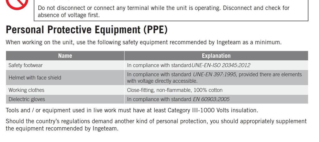
4 6.1 Safety requirements Required elements Instrumentation Documentation PC Software Accesories /54
5 1 INTRODUCTION The purpose of this document is to guide through the different ways of resolution for the events that can appear in inverters of the family of Ingecon Sun Storage 1 Play. The document is divided in three big blocks: - EVENTS: In this section all events are defined. Alarms, stop events and warnings are included as events. - INCIDENT WORKFLOW: Each event has a diagram guide to solve the problem that is causing the event. Along the different diagrams there are instructions that are defined and explained in the next block - TRAINING INSTRUCTIONS: Explanation of different operations to do in the inverter. This block is divided in other subblocks 5/54
6 2 EVENTS 2.1 DEFINITIONS Alarms Alarms are events that produce the stop of the normal working state of the ISS 1Play. An alarm event may be transient or maintained in time as a stable condition. It is important to understand that stopping the normal working state of the ISS 1Play does not lead to the device to be completely stopped, only part of all the alarms may force the ISS 1Play to stop. For example, while with an Alarm0x0004H (grid voltage out of range) the device will not stop in some operation modes, with an Alarm0x0008H (HW failure) will always do. The alarm is defined by a 32bit code. Every alarm code has a display text associated and is intended to be general; so to get its complete meaning will be necessary to use the Unit Operating Codes (Code 1 and Code 2) and the Stop Event parameter too. Every time that an alarm is produced the associated bit in the 32bit code will set. The active state of the bit will last until a new connection will be attempted. This way to process alarms without resetting the bit, will lead to a situation where it is impossible to know if the alarm displayed has occurred once or maybe it is happening continuously, on the other hand, it will let to know if transient alarms have happened. In case that more than one alarm is shown at the same time, both hexadecimal codes will be shown together. An example with the two grid alarms (Alarm 0x0002 and Alarm 0x0004) is included below: Alarm 0x Hex = 0x Alarm 0x Hex = 0x Alarm 0x Hex = 0x Alarms can be checked through: LED: the orange led permanently glowing (ON state) will indicate the presence of an alarm. Display: a specific menu lets to check the alarms in the device, it is accessible through MAIN MENU > MONITORING > ALARM MONIT. Datalogger. It can be checked using the Ingecon Sun Manager software. For further information see the Installation and Operation Manual. 6/54
7 2.1.2 Unit Operating Codes (Code1 and Code2) The Unit Operating Codes are intended to give more information about the reason why an alarm occurred. Each code is defined in a 16 bit variable, in hexadecimal and named as Code1 and Code2. As it happens in Alarms, if more than a unit operating code is happening at the same time they are added as shown previously. Code1 and Code2 can be checked through: Display: a specific menu lets to check the alarms in the device, it is accessible through MAIN MENU > MONITORING > ALARM MONIT. Datalogger. It can be checked using the Ingecon Sun Manager software. For further information see the Installation and Operation Manual Stop Event Since alarm code are intended to be general events and something understandable by users, stop events are also defined. Stop events are more specific and more descriptive codes. Therefore, one alarm code may be associated to several stop event codes. At the end, stop event will fully describe the produced alarm. It will depend on the hardware, device and any factor the developer might take into account. Stop event is defined by a 32bit code, where the bit position means the number of the stop event. An example, with the two stop event (1 and 10) is included below: Stop event 1 and 10 = Stop events can be checked through: Datalogger. It can be checked using the Ingecon Sun Manager software Warning A warning is a situation of the unit that requires maintenance. However, it does not mean a stop event. A warning event will be highlighted by the blinking of the orange led and the corresponding bit code in the unit operating codes LEDS MEANING The LEDs meaning is explained in the Installation and Operation Manual 7/54
8 3 Origin and description of the events ALARMS UNIT OPERATING CODES STOP EVENT DESCRIPTION 0x Battery voltage out of range Code 2: 0x0080 Low battery voltage. Stop Event: 1 The stop event is active only when the inverter is with this alarm and is not connected to a grid/genset This is because the battery is the only energy source available to feed the loads, but it is already to the minimum so the inverter must stop. It may be caused by the battery protection, Vbat<Vbatmin, or by the strategy, SOC<SOCdescx *. (*)In lead acid three phase systems there is not SOC estimation so the condition is Vbat<Vbatdescx). The alarm will be active until Vbat>Vbatmin and SOC>SOCrecx**. (**)In lead acid three phase systems there is not SOC estimation so the condition is Vbat>Vbatrecx). Code 2: 0x0100 High battery voltage. Stop Event: 2 The high limit is above a temporized limit or an instantaneous limit. Each limit depends on the type of battery: Lead-Acid: the high limit is defined as Vnom x 125%. If the lead-acid allows an equalization charge, the high limit is defined as Vequalzation x 106%. 0x Grid frequency out of range 0x Grid voltage out of range Code 2: 0x0008 Stop Event: 5 Code 2: 0x0040 Stop Event: 5 The stop event is active only when the inverter is with this alarm, is connected to a grid/genset and the backup function is disabled. The stop event is active only when the inverter is with this alarm, is connected to a grid/genset and the backup function is disabled. Lithium: the high limit is defined by the battery manufacturer. Frequency out of the configured limits. These limits depends on the type of grid: Genset: the limits are defined by the genset manufacturer. Grid: the limits are defined by the grid standards. If the backup function is enabled, the inverter disconnects from the grid and generates the grid itself. If the backup function is disabled, the inverter stops. Voltage out of the configured limits. These limits depends on the type of grid: Genset: the limits are defined by the genset manufacturer. Grid: the limits are defined by the grid standards. If the backup function is enabled, the inverter disconnects from the grid and generates the grid itself. If the backup function is disabled, the inverter stops. 0x DC/AC converter overcurrent or fault 0x DC/DC converter overcurrent or fault 0x Insulation failure Not used. Stop Event: 7 DC/AC converter has detected an overcurrent or an IGBT fault. Not used. Stop Event: 8 DC/DC converter has detected an IGBT fault. Stop Event: 9 DC/DC converter has detected an overcurrent. Code 1: 0x0004 Stop Event: 21 Insulation failure to positive or negative PV or Battery terminals. Code 1: 0x0400 Stop Event: 19 RMS differential current failure: >240mA. Code 1: 0x0800 Stop Event: 18 Incremental differential current failure: 25, 50 or 125mA. 8/54
9 0x Synchronization alarm in 3 Phase systems 0x Temperature alarm 0x DC bus overvoltage 0x Configuration change 0x Inverter stopped 0x HW failure Code 1: 0x1000 Stop Event: 20 Instantaneous differential current failure: >330mA. Code 2: 0x0002 Stop Event: 22 In three phase systems: Synchronization wire not properly connected or one of the inverters has a stop event. Not used. Stop Event: 16 Low temperature in Sink: <= -20.5ºC. Stop Event: 17 High temperature in PCB or Sink. Not used. Stop Event: 6 DC bus voltage over the limits: >550Vdc Not used. Stop Event: 25 Change in the configuration done. Code 1: 0x2000 Stop Event: 10 Inverter stopped by the display or remote communication. Code 2: 0x8000 Stop Event: 4 Inverter stopped by the digital input. Not used. Stop Event: 24 Bad readings from analog/digital converter (ADC). Code 1: 0x0002 Not used. Averaged grid current out of the 25%- 75% full scale range. Code 1: 0x0020 This alarm is active before the inverter start-up. Averaged DC/DC boost converter current out of the 25%-75% full scale range. Code 1: 0x0040 Code 1: 0x0080 DC offset in the DC/AC converter current cannot be compensated. Grid voltage measurement is out of the 25%-75% full scale range. Code 1: 0x0100 Averaged differential current out of 25%- 75% of full scale range. Code 1: 0x0200 Instantaneous differential current over 25% of full scale. Code 2: 0x4000 Internal differential current test failed. Not used. Stop Event: 29 Stack overflow. Reset Watchdog. Not used. Stop Event: 28 analog/digital converter (ADC) acquisition not occurred in 1 ms. Code 2: 0x0020 Stop Event: 15 Internal AC relay test failed. The inverter cannot connect to the grid. 0x DC/DC or AC/DC Converter Error 0x Overload capacity exceeded in AC Grid 0x High Battery Temperature 0x Overload capacity Not used. Stop Event: 23 DC/DC or AC/DC converter has detected five IGBT fault within 5 min. The inverter will keep stopped for 1min. Not used. Stop Event: 26 Overcurrent in the AC Grid Port. The loads are higher than the AC Grid Port s capacity during 10 seconds (check datasheet Generator or grid maximum power ) Not used. Stop Event: 17 The stop event is active only when the inverter is with this alarm and is not connected to a grid/genset. The Lead-Acid battery temperature is too high (> 50ºC). Wait for the battery to cool down. This alarm is deleted when the battery temperature is < 47ºC. Protect the battery against temperatures above 25ºC. This helps prevent premature aging of the battery. Not used. Stop Event: 12 Overcurrent in the AC Loads with the inverter not connected to the grid. There are 3 protection levels: 30 mins, 2 9/54
10 exceeded in AC Loads 0x Short circuit in AC Loads 0x PT100 sensor 0x Communication Error with the BMS mins and 3 secs. Not used. Stop Event: 11 Overcurrent in the battery with the inverter not connected to the grid. There are 3 protection levels: 30 mins, 2 mins and 9 secs. Not used. Stop Event: 13 Short circuit in AC Loads. When detected (VacLoads <26 V and high current) the inverter disconnects in 40 ms. Not used. Not used. The PT100 temperature sensor can be disconnected short-circuited or cable break. Ensure that the battery temperature sensor is correctly connected. Code 2: 0x0200 Stop Event: 3 The stop event is active only when the inverter is with this alarm and is disconnected to a grid/genset. When the inverter is disconnected to the grid, it will stop within 5 seconds after loss of communication occurs. The inverter will recover automatically when communication is established again. If the inverter is connected to the grid, it will keep connected without using the battery. 0x Not used. Not used. The inverter has a wrong serial number. Wrong inverter serial number 0x High grid voltage 0x Wrong type of battery configuration 0x BMS alarm Not used. Stop Event: 5 This alarm is active before the inverter start-up. The stop event is active only when the inverter is with this alarm, is connected to a grid/genset and the backup function is disabled. Instantaneous Vac High protection: If the backup function is enabled, the inverter disconnects from the grid and generates the grid itself. If the backup function is disabled, the inverter stops. Not used. Stop Event: 27 The inverter keeps stopped if a frame of a Battery Management Systems (BMS) is detected with the configuration set to Lead Acid. The battery settings must be corrected. Code 2: 0x2000 Stop Event: 30 When the inverter is disconnected to the grid, it will stop. The inverter will recover automatically when alarm in the BMS disappears. If the inverter is connected to the grid, it will keep connected without using the battery. 10/54
11 WARNINGS UNIT OPERATING CODES Code 1: 0x0008 Code 1: 0x0010 Code 2: 0x0001 Code 2: 0x0010 Code 2: 0x0800 Code 2: 0x1000 DESCRIPTION Internal fan has detected a fault. The fan will keep stopped while it is blocked. External fan has detected a fault. The fan will keep stopped while it is blocked. Inverter has detected high temperature in PCB or Sink. If the inverter is connected to the grid, it will regulate AC output power. DC offset in the DC/AC converter current has been compensated without enough accuracy. Error in the phase sequence of the three phase system. Inverter configurated as Phase S or Phase T has detected error in the phase sequence of the grid. The inverter will not connect to the grid while this warning is active. The digital input of the inverter has detected an error in the status of the external AC grid contactor. 11/54
12 4 INCIDENT WORKFLOW This section shows the workflow diagram necessary to follow to resolve the incidents that could be detected through the different events explained above. MEANING OF COLOR WORKFLOW ELEMENTS HW COMPROBATIONS HW FAILURE HW REPLACEMENTS POSSIBLE ABRMAL INVERTER SITUATION CALIBRATIONS WORKFLOW INSTRUCTION WORKFLOW RESOLUTION CHECKING MEASURES WORKFLOW COMPROBATION 12/54
13 4.1 Alarm 0x , Code 2 0x0080: Stop Event 1 Vbat Low ALARM 0x Code 2 0x0080 Vbat low Is there the Alarm 0x80000 BMS COM showing as well? Fix before the 0x80000 alarm BMS COM ERROR Stop the inverter and disconnect the PV Array from the ISS 1Play Measure the Battery Voltage with a voltimeter on the Inverter s terminals. Learn in how to do it Name this measure Vbat_Inv Get the Nominal Voltage of your whole Battery Bank. Name this value Vnom Check the wires between the battery and the inverter Is Vbat_Inv > Vnom*0.9? Measure the Battery Voltage with a voltimeter on the Battery Bank s terminals. Is Vbat_Inv Vbat > 2V? Very Important keeping the Name this measure Vbat inverter stopped. Check the Minimum Battery Voltage on the Inverter s configuration Are battery cells functional? Learn in how to do it Learn in how to do it Name this value Vbat_min Fix the battery bank The battery bank needs to be charged Is Vbat_Inv > Vbat_min? Does that Vbat_min make sense with your battery specifications? Obtain the State of Charge ( SOC ) value from the Inverter s monitoring data Obtain the Disconnection State of Charge ( SOCdescx ) and Reconnection State of Charge ( SOCrecx ) value from the Inverter s Configuration Set a correct Vbat_min value in the Inverter s Configuration Is SOC >= SOCrecx? Does SOCrecx and SOCdescx make sense for your desired strategy? Fix the SOCrecx and SOCdescx settings to more suitable ones Upgrade INVERTER FW See Does the problem dissapear? Fully charge the battery bank to reset the SOC estimation. For Lead Acid Batteries, it is essential setting correctly C20h and C5h parameters for a good SOC estimation See how to it in the FAQ chapter The problem is solved with the FW update Contact INGETEAM Technical Support 13/54
14 4.2 Alarm 0x Code 2 0x0100: Stop Event 1 Vbat High ALARM 0x Code 2 0x0100 Vbat high Is there the Alarm 0x80000 BMS COM showing as well? Fix before the 0x80000 alarm BMS COM ERROR Has the ISS 1Play a PV Array connected? Disconnect the PV Array and check this alarm again Check the Charge Voltages on the Inverter s configuration. For Lead-Acid battery: check the absorption, flotation and equalization parameters. For Lithium battery: check Charge Voltage from Inverter s monitoring data Does those values match with your battery bank s requirements? Fix the Charge Voltage parameters Upgrade INVERTER FW See Does the problem dissapear? The problem is solved with the FW update Contact INGETEAM Technical Support 14/54
15 4.3 Alarm 0x and Alarm 0x ALARM: 0x Fac out of range 0x Vac out of range Is the alarm showing now? It might has been a transient: If your grid is too weak, avoid sudden connection/disconnection of big loads. IT IS GENERATOR Does the configured Type of Grid match with your installation?. IT IS GRID Set a correct TYPE OF GRID See Set a correct COUNTRY/REGULATION See Set a correct MINAL GRID VOLTAGE MINAL GRID FRECUENCY See Set correct GRID VAC/FAC LIMITS See The COUNTRY/REGULATION configured is correct? SI The V/FSETTINGS configured are correct? The V/FSETTINGS match with the Genset s datasheet? Set correct GENERATOR VAC/FAC LIMITS See Access inside the inverter Measure the Grid/Genset Voltage and Frequency on the Inverter s Terminal with a multimeter See Wait until the Vac or Fac returns within Limits Compare these measurements with the V/F Settings. Are they out of limits? Contact INGETEAM Technical Support 15/54
16 4.4 Alarm 0x : Stop Event 7 DC/AC Converter s Overcurrent or Fault ALARM Code: 0x DC/AC Overcurrent or Fault Is it the positive or negative pole of the PV panel (See 5.2.4) or battery (See 5.2.2) GROUNDED? Due to the inverter s topology, it is T ALLOWED. Use ungrounded PV and battery solutions. Is the Inverter not working anymore, showing as well the Alarm 0x ? Contact INGETEAM Technical Support Upgrade INVERTER FW See Does the problem disappear? The problem is solved with the FW update Try to measure the Grid s Vac (See 5.2.5) in an oscilloscope. Transients in the AC installation affect the inverter Has Vac suffered an abrupt transient? Contact INGETEAM Technical Support. Send them if possible a oscilloscope capture 16/54
17 4.5 Alarm 0x : DC/DC Converter s Overcurrent (Stop Event 9) or Fault (Stop Event 8) ALARM Code: 0x DC/DC Overcurrent or Fault Which is the Stop Event? See Nº 9. OVERCURRENT Fix the Battery POLARITY Nº 8. IGBT FAULT Is the Battery POLARITY in the correct position on the Inverter? Upgrade INVERTER FW See Does the problem dissapear? The problem is solved with the FW update Contact INGETEAM Technical Support 17/54
18 4.6 Alarm 0x : Insulation failure ALARM Code: 0x Insulation Failure Check the Insulation of the following poles: - Battery Port: See PV Port: See Is it any of these measurements less than 15V? It is on the installation Disconnect the wires and check the insulation problem. Is it inside the inverter or in the installation? It is inside the inverter Is the alarm shown when the inverter just goes On-Grid? Due to the inverter s topology, it is T ALLOWED. Use ungrounded PV and battery solutions. Contact INGETEAM Technical Support Check the AC Grid Wires Disconnect AC Loads and try a reconnection There was a leak in the AC Grid side Does the alarm disappear? Does the alarm disappear? Upgrade INVERTER FW See Check the AC Loads Installation Does the problem disappear? The problem is solved with the FW update Contact INGETEAM Technical Support 18/54
19 4.7 Alarm 0x : Stop Event 22. Synchronization alarm in 3 Phase Systems. ALARM Code: 0x Synchronization Before dealing with this alarm, read carefully the chapter dedicated to three-phase systems in the Installation and Operation Manual Very Important Check the Inverter s configuration for the AC Phase of the Inverter See For Single Phase Installation Set Single Phase For Three-Phase Installation R,S,T. Each one for each inverter The inverters were wrongly configured Does the alarm disappear? Fix that alarm first Is it any of the 3 inverters showing an additional alarm? 3 INVERTERS WITH TYPE A Which types of Hardware do you have? See in the Installation and Operation Manual How to do it 3 INVERTERS WITH TYPE B - Check that the Phase of the previous inverter is correctly connected in J61. - Check that the previous inverter is Generating the expected voltage. It can be done seeing the Inverter s AC Load Vac. DIFFERENT TYPES Contact INGETEAM Technical Support - Check that the RX/TX of the previous inverter is correctly connected in J75. - Check that the previous inverter is Generating the expected voltage. It can be done seeing the Inverter s AC Load Vac. Are those checking OK? The previous inverter must be generating and the synchronization cable correctly wired Are those checking OK? Disconnect all the Loads to let the Inverters generating in open circuit After 30 seconds, do the 3 inverters generate correctly? Upgrade INVERTER FW See The loads transients seem to affect the inverter. Check that they are correctly sized. Ingeteam recommends the use of frequency drives to avoid transient voltage drops (2-3 seconds) during their connection The problem is solved with the FW update Does the problem disappear? Contact INGETEAM Technical Support 19/54
20 4.8 Alarm 0x : Temperature. Stop Events 16 and 17. ALARM Code: 0x Temperature Perform the Fan s Test See Has Code 1 = 0x0008 or Code 1 = 0x0010 appeared during the test? Check visually the fan s. If there is an object blocking the fans, remove it. Otherwise, Contact INGETEAM Technical Support Clean up the inverter The ventilation conduct is free of dust and the air can flow through the radiator correctly? Upgrade INVERTER FW See The environment of the unit is appropriate as is described in the section ENVIRONMENTAL CONDITIONS of the Installation and Operation Manual? Does the problem disappear? Inverter is working at not enough refrigeration or heating conditions The problem is solved with the FW update Contact INGETEAM Technical Support RECONSIDER THE LOCATION of the unit 20/54
21 4.9 Alarm 0x : DC Bus Overvoltage. Stop Event 6. ALARM Code: 0x DC Bus Overvoltage Has the Inverter a PV Array Connected? Is the Open Circuit Voltage out of the Datasheet range? See Upgrade INVERTER FW See The PV ARRAY HAS BEEN SIZED INCORRECTLY Contact the PV designing team Does the problem disappear? The problem is solved with the FW update Contact INGETEAM Technical Support 21/54
22 4.10 Alarm 0x : Configuration Change. Stop Event 25. ALARM Code: 0x Configuration Change RMAL Alarm and Stop Event due to a change in the inverter settings 4.11 Alarm 0x : Stop Inverter Command. ALARM Code: 0x Inverter Stopped Nº10. DISPLAY OR COMMS CODE 1 = 0x2000 Command the Inverter to Start See Which is the Stop Event? See Code 1 and 2 also give this information Nº 4. DIGITAL INPUT CODE 2 = 0x8000 Check the Digital Input s configuration Fix the Digital Input Configuration. If you don t have any digital input, set it to No Configured Do you really want a digital input that stops the inverter? Switch it to start Is the digital input status commanding a stop? Check the digital input s connection. There are some digital input s, such as DRM0, that cause the stop when they are wrongly connected. 22/54
23 4.12 Alarm 0x : HW Failure. ALARM Code: 0x HW Failure Which is the Stop Event? See Code 1 and 2 also give this information Stop Events = 24, 28 or 29 Code 1 = 0x0002, 0x0020, 0x0040, 0x0080, 0x0100 or 0x0200 Code 2 = 0x4000 Stop Event 15 Code 2 0x0020 Stop the Inverter. See Very Important! Measure the Impedance between Loads and Grid/Genset Ports See Is Line to Line and Neutral to Neutral Impedance greater than 30kOhms? Does your Grid Installation use a TT or TN type topology? TT Upgrade INVERTER FW See TN Disable partially or totally the Relay Test. Does the problem disappear? TE: This instruction can be performed only by a qualified installer. Contact to INGETEAM Technical Support anyway The problem is solved with the FW update Contact INGETEAM Technical Support 23/54
24 4.13 Alarm 0x : Repetitive DC/DC or DC/AC Error. Stop Event 23. ALARM Code: 0x Repetitive Error This Alarm is because there has been several consecutive Alarm 0x0008 or Alarm 0x0010. The Inverter is kept stopped for 1 min and then automatically restarted. Solve Alarms 0x0008 or 0x Alarm 0x : Overload in AC Grid Port. Stop Events 26. ALARM Code: 0x Overload in Grid Port - Check the Generator or grid maximum power 1Play Datasheet - Estimate the power consumed by your loads Is the Loads Power greater than the AC Grid Port capacity? To show the alarm they must be greater during 10 seconds Disconnect one by one the loads connected The installation is not able to feed such a big load. Reduce the consumption. Does the alarm disappear? Contact INGETEAM Technical Support 24/54
25 4.15 Alarm 0x : High Battery Temperature. Stop Events 17. ALARM Code: 0x High Battery Temperature Check the battery temperature sensor (PT100). See Is the Battery Temperature Sensor (PT100) correctly connected? Ensure that the battery temperature sensor (PT100) is correctly connected. Wait for the battery to cool down. This alarm is deleted when the battery temperature is < 47ºC. Protect the battery against temperatures above 25ºC. This helps prevent premature aging of the battery. The battery temperature has been too high. Does the alarm disappear? Contact INGETEAM Technical Support 25/54
26 4.16 Alarm 0x : Overload in AC Loads Port. Stop Events 11 and 12. ALARM Code: 0x Overload in Loads Stop Event 11 Which is the Stop Event? Stop Event 12 See Check the Battery s Discharge Current on the configuration See Check the Output (AC) Current on the ISS 1Play Datasheet Is it correctly set according with your installation specifications? Set correctly the parameter Disconnect one by one the loads connected The installation is not able to feed such a big load. Reduce the consumption. Does the alarm disappear? Contact INGETEAM Technical Support 4.17 Alarm 0x : Short circuit in AC Loads. Stop Event 13. ALARM Code: 0x Short Circuits in Loads Disconnect all the Loads from the Inverter s AC Loads Port Does the alarm disappear? Contact INGETEAM Technical Support Review the Loads Connected to the Inverter. A short circuit has been detected 26/54
27 4.18 Alarm 0x : PT100 Temperature sensor. ALARM Code: 0x PT100 Sensor This Alarm is because there is a short circuit or cable break in the battery temperature sensor. 27/54
28 4.19 Alarm 0x and 0x : Communication Error with the BMS. ALARM Code: 0x Battery Com Error 0x Wrong type of battery config Have you got a battery with BMS? Review you type of battery. Set it to No configured if there is no battery or to Lead Acid for Batteries without BMS See Is the type of Battery Correctly Configured? See Set a battery type according with the battery connected Check the communication between the Battery and the Inverter. See Was it correctly done? The communication was not correctly wired CAN Which protocol is used to communicate the BMS Information to the Inverter? RS485 Check the RS485 Communication Timeout on the ISS 1Play s Configuration. See Is the display working correctly? See Does the BMS refresh the communication within the timeout? Contact INGETEAM Technical Support Set a correct timeout according to the BMS communication period. Upgrade INVERTER FW See Does the problem disappear? The problem is solved with the FW update Contact INGETEAM Technical Support 28/54
29 4.20 Alarm 0x : Wrong Inverter Serial Number. ALARM Code: 0x Wrong Inverter Serial Number Check the Inverter s Serial Number reading it with Ingecon Sun Manager or Display Does it match with the one in the rating plate? Contact INGETEAM Technical Support indicating the result of this question 4.21 Alarm 0x : High Instantaneous Grid Voltage. Stop Event 5. ALARM Code: 0x Instantaneous High Vac One of the possible causes could be that the Grid s Circuit Breaker is opened. Is the Grid s Circuit Breaker tripped? Check your grid installation and switch on again the Circuit Breaker The Grid voltage is higher than the maximum limit allowed by the grid code. 29/54
30 4.22 Alarm 0x : Alarm in the BMS. Stop Event 30. Code 2 0x2000 ALARM Code: 0x Alarm reported by the BMS The BMS has reported an error. The inverter will be recovered automatically when the alarm in the BMS disappears. 30/54


31 5 TRAINING INSTRUCTIONS 5.1 CHECKING MEASURES Inverter measures Vbat measurement is correct? Stop the inverter Access inside the inverter Measure the Battery Voltage with a polimeter. See instructions Read trough ISM or DISPLAY the inverter measurement Vbat Calculate the inverter measurement error % = % < 1%? 31/54

32 5.1.2 All battery cells are functional? Keep the inverter stopped. Get the Nominal Cell Voltage from the Battery s Datasheet Name this VnomCell Measure with a voltimeter each battery cell Name this Vcell A battery cell is not defective? 0,9*VnomCell > Vcell > 1,4*VnomCell Check the communication between de battery and the inverter. The communication between the battery and the ISS 1Play can be with CAN or RS485 Protocol. Batteries with CAN Protocol This point asks for reviewing the wiring of the CAN communication between the battery and the inverter. For a correct communication the following points must be all right: - The battery and the inverter must be switched ON. - The wiring must be well connected. Check the Installation and Operation Manual of the Inverter to see in which position are placed. Compare it with the Battery s BMS s wire convention. For some batteries, such as LG Resu model, Ingeteam released a dedicated commissioning guide. For getting those guides, Contact with Ingeteam Technical Service. Depending on the CAN Battery connector, the text on the PCB change. Batteries with RS485 Protocol For a correct communication the following points must be all right: - The battery and the inverter must be switched ON. - The RS485 wiring must be well connected in the Inverter s communication board. For further details, Contact Ingeteam Technical Service Check that the display is working correctly. The display is connected to the inverter s Printed Circuit Board through a set of wires to provide the electrical power supply and the CAN communication. When a display is not working correctly, it is not turned on or just after turning on it starts with the hour at 00:00. 32/54

 is installed between R-W pins.")
33 5.1.5 Check the battery temperature sensor (PT100). This point asks for reviewing the wiring of the battery temperature sensor. For a correct temperature of the battery bank the following points must be all right: - The wiring must be well connected. Check the Installation and Operation Manual of the Inverter to see in which position are placed. - If the type of PT100 sensor is 2-wires, it is necessary short circuit the R-R pins and the PT100 (2-wires) is installed between R-W pins. - If the type of PT100 sensor is 3-wires, the PT100 is installed in R-R-W pins. 33/54


34 5.2 MEASUREMENTS ON INVERTER TE: The multimeter have to be connected on the measuring points during the entire process, calibration or checking inverter measures. Insert and remove the multimeter on these points could affect the measures because of its internal impedance. All the measurements must be done with the inverter powered up, if other thing is not expressly indicated. See the Safety Requiremets in the annex Measure the Battery Voltage with a voltimeter on the Inverter s terminals. Depending on the type of Battery Connector, the test point to place the voltimeter changes: Check the Battery s Insulation. This measuremen st goal is to check the voltage between the Positive and Negative to Ground. Depending on the type of Battery Connector, the test point to place the voltimeter changes: Measure PV panel s open circuit Voltage. In order to have an accessible point to place the voltimeter s probe, it is recommended to disconnect the multicontacts. To avoid an electric arc, put before the disconnection the inverter in Manual Stop. Measure the voltage between the two Multicontact aereal conectors. 34/54


35 5.2.4 Check the PV Array s Insulation. This measurement s goal is to check the voltage between the Positive and Negative to Ground. In order to have an accessible point to place the voltimeter s probe, it is recommended to disconnect the multicontacts. To avoid an electric arc, put before the disconnection the inverter in Manual Stop Measure the Grid/Genset Voltage and Frequency on the Inverter s terminals. Depending on the type of Grid Connector, the test point to place the voltimeter changes: Check the Load Port s Insulation. This measurement s goal is to check the voltage between the Line and Neutral to Ground. 35/54


.")


36 Depending on the type of Battery Connector, the test point to place the voltimeter changes: Check the Grid/Genset Port s Insulation This measurement s goal is to check the voltage between the Line and Neutral to Ground. Depending on the type of Battery Connector, the test point to place the voltimeter changes: Measure the Voltage between Loads and Grid/Genset Ports Measure the Voltage between Loads and Grid/Genset Ports. Do it without disconnecting the Loads Port and Grid/Genset Port s wires but with the inverter in Manual Stopped (Very Important!). Depending on the type of Battery Connector, the test point to place the voltimeter changes: With the voltmeter in red is measured the L-L and with the one in black the N-N Measure the Impedance between Loads and Grid/Genset Ports Measure the Impedance between Loads and Grid/Genset Ports. Do it without disconnecting the Loads Port and Grid/Genset Port s wires but with the inverter in Manual Stopped (Very Important!). 36/54


37 Depending on the type of Battery Connector, the test point to place the voltimeter changes: With the ohmeter in red is measured the L-L and with the one in black the N-N 37/54

38 Measure the DC/AC Inductor s Current. Embrace the wire of the picture with a current probe: 38/54
39 5.3 BASIC CONFIGURATION CHANGES Set COUNTRY/REGULATION Select the country where the inverter will be installed. If the country is not on the list, select Worldwide. Then, select the applicable regulation. This can be done using the Ingecon Sun Manager software package (downloadable on or through the display: Using Ingecon Sun Manager: Settings 4.- GRID SETTINGS Figure 1: Country Regulation Selection on Ingecon Sun Manager Click on the Send button. A screen informing that the configuration was successfully saved must appear when the settings are correctly applied to the inverter. Using Display: To perform any configuration change through the display, the required installer password must be entered on: MAIN MENU > CONFIGURATION > ENTER PASSWORD The password (0332) is indicated on the Installation and Operation Manual, on the chapter dedicated to configuration. When the permission is given, go to: MAIN MENU > CONFIGURATION > GRID/GENSET > TYPE OF GRID > GRID > COUNTRY REGULATION Confirm the desired selection by pressing the OK button. A message to confirm the modification will pop up. A final screen that shows that the process has been completed will be shown on the display Set TYPE OF GRID Select the type of grid that the ISS 1PLAY STORAGE is connected to in this moment. This can be done using the Ingecon Sun Manager software package (downloadable on or through the display: Using Ingecon Sun Manager: Settings 2.-AC INSTALLATION TYPE: Type of Grid Click on the Send button. A screen informing that the configuration was successfully saved must appear when the settings are correctly applied to the inverter. Using Display: To perform any configuration change through the display, the required installer password must be entered on: MAIN MENU > CONFIGURATION > ENTER PASSWORD 39/54
40 The password (0332) is indicated on the Installation and Operation Manual, on the chapter dedicated to configuration. When the permission is given, go to: MAIN MENU > CONFIGURATION > GRID/GENSET > TYPE OF GRID Confirm the desired selection by pressing the OK button. A message to confirm the modification will pop up. A final screen that shows that the process has been completed will be shown on the display Set MINAL VAC AND FAC Selecting a correct nominal AC Voltage and Frequency are essential because otherwise some malfunctionings may occur. This can be done using the Ingecon Sun Manager software package (downloadable on or through the display: Using Ingecon Sun Manager: Settings 2.- AC INSTALLATION TYPE: Nominal Voltage Settings 2.- AC INSTALLATION TYPE: Nominal Frequency Click on the Send button. A screen informing that the configuration was successfully saved must appear when the settings are correctly applied to the inverter. Using Display: To perform any configuration change through the display, the required installer password must be entered on: MAIN MENU > CONFIGURATION > ENTER PASSWORD The password (0332) is indicated on the Installation and Operation Manual, on the chapter dedicated to configuration. When the permission is given, go to: MAIN MENU > CONFIGURATION > INVERTER > RMS VOLTAGE MAIN MENU > CONFIGURATION > INVERTER > FREQUENCY Confirm the desired selection by pressing the OK button. A message to confirm the modification will pop up. A final screen that shows that the process has been completed will be shown on the display Set GENERATOR VAC/FAC SETTINGS Selecting a correct AC Voltage and Frequency Limits are essential for avoiding malfunctioning and protecting the genset. This can be done using the Ingecon Sun Manager software package (downloadable on or through the display: Using Ingecon Sun Manager: Settings 3.- GENERATOR SETTINGS 40/54
41 Set there the Generator parameters according to the one you are using. Click on the Send button. A screen informing that the configuration was successfully saved must appear when the settings are correctly applied to the inverter. Using Display: To perform any configuration change through the display, the required installer password must be entered on: MAIN MENU > CONFIGURATION > ENTER PASSWORD The password (0332) is indicated on the Installation and Operation Manual, on the chapter dedicated to configuration. When the permission is given, go to: MAIN MENU > CONFIGURATION > GRID/GENSET > TYPE OF GRID > GENERATOR Set there the Generator parameters according to the one you are using. Confirm the desired selection by pressing the OK button. A message to confirm the modification will pop up. A final screen that shows that the process has been completed will be shown on the display Set GRID VAC/FAC SETTINGS Selecting a correct AC Voltage and Frequency Limits are essential for avoiding malfunctioning and complying with the grid standard. This can be done using the Ingecon Sun Manager software package (downloadable on or through the display: Using Ingecon Sun Manager: Settings 4- GRID SETTINGS Check all that are the Grid Settings are correct. Bear in mind that the values are referred to the Nominal Voltage and Frequency. Click on the Send button. A screen informing that the configuration was successfully saved must appear when the settings are correctly applied to the inverter. Using Display: To perform any configuration change through the display, the required installer password must be entered on: MAIN MENU > CONFIGURATION > ENTER PASSWORD The password (0332) is indicated on the Installation and Operation Manual, on the chapter dedicated to configuration. When the permission is given, go to: MAIN MENU > CONFIGURATION > GRID/GENSET > TYPE OF GRID > GRID >V/F SETTINGS Check all that all the Grid Settings are correct and then confirm the desired selection by pressing the OK button. A message to confirm the modification will pop up. A final screen that shows that the process has been completed will be shown on the display. 41/54
42 5.3.6 Set BATTERY CAPACITY VALUES (C20h and C5h) In the batteries without Battery Management System (BMS), such as the Lead Acid ones, the State of Charge (SOC) estimation must be made by the inverter. In order to do it correctly, it is essential setting correctly the C20h and C5h parameters. This can be done using the Ingecon Sun Manager software package (downloadable on or through the display: Using Ingecon Sun Manager: Settings 4- GRID SETTINGS Check all that are the Grid Settings are correct. Bear in mind that the values are referred to the Nominal Voltage and Frequency. Click on the Send button. A screen informing that the configuration was successfully saved must appear when the settings are correctly applied to the inverter. Using Display: To perform any configuration change through the display, the required installer password must be entered on: MAIN MENU > CONFIGURATION > ENTER PASSWORD The password (0332) is indicated on the Installation and Operation Manual, on the chapter dedicated to configuration. When the permission is given, go to: MAIN MENU > CONFIGURATION > GRID/GENSET > TYPE OF GRID > GRID >V/F SETTINGS Check all that all the Grid Settings are correct and then confirm the desired selection by pressing the OK button. A message to confirm the modification will pop up. A final screen that shows that the process has been completed will be shown on the display Set Inverter s configuration for the AC Phase of the Inverter This parameter indicates if the inverter is installed in a Single Phase Installation or in a Three Phase One. In the last case, the phase in which the inverter is installed must be specified (R,S,T). So it must be checked in the 3 inverters. This can be done using the Ingecon Sun Manager software package (downloadable on or through the display: Using Ingecon Sun Manager: Settings 2- AC INSTALLATION TYPE AC Phase Inverter Click on the Send button. A screen informing that the configuration was successfully saved must appear when the settings are correctly applied to the inverter. Using Display: To perform any configuration change through the display, the required installer password must be entered on: 42/54
43 MAIN MENU > CONFIGURATION > ENTER PASSWORD The password (0332) is indicated on the Installation and Operation Manual, on the chapter dedicated to configuration. When the permission is given, go to: MAIN MENU > CONFIGURATION > INVERTER > AC PHASE Check all that all the Grid Settings are correct and then confirm the desired selection by pressing the OK button. A message to confirm the modification will pop up. A final screen that shows that the process has been completed will be shown on the display Check and Change BATTERY S MAXIMUM DISCHARGING CURRENT SETTING Reading the Maximum Discharging current for the Battery Read the Input Register It can be done with the Manager searching the name Battery.Max.Discharging Current in Online Data Section. Changing the Maximum Discharging current for the Battery The Maximum Discharging Current is specified in the configuration for Lead Acid Batteries (Using Ingecon Sun Manager: Settings Lead Acid Battery Settings: Max Discharge current) or is given by the BMS for Lithium Batteries Set TYPE OF BATTERY It is required to set the DC Source type. Select the following options: - CONFIGURATION: If you don t have a Battery Connected or it is no longer in use. - LEAD ACID: For Lead Acid Batteries. They don t need communications. - OTHERS: There is a List of Approved Lithium-Ion Batteries with Ingecon Sun Storage 1PLAY. All of them needs communication to indicate to the Inverter the BMS data. This can be done using the Ingecon Sun Manager software package (downloadable on or through the display: Using Ingecon Sun Manager: Settings 1-.DC BATTERY TYPE: Type of Battery. Figure 2: DC Source selection on Ingecon Sun Manager. Click on the Send button. A screen informing that the configuration was successfully saved must appear when the settings are correctly applied to the inverter. Using Display: To perform any configuration change through the display, the required installer password must be entered on: MAIN MENU > CONFIGURATION > ENTER PASSWORD 43/54


 5.")
44 The password (0332) is indicated on the Installation and Operation Manual, on the chapter dedicated to configuration. When the permission is given, go to: MAIN MENU > CONFIGURATION > BATTERY Confirm the desired selection by pressing the OK button. A message to confirm the modification will pop up. A final screen that shows that the process has been completed will be shown on the display Check the RS485 Communication Timeout. For Batteries that use RS485 protocol, it is necessary updating the communication within the configured Timeout. This timeout can be checked or configured with Ingecon Sun Manager. The default value is 1800 ms. Settings 8.1-.Communication Settings: Timeout for Grid Support Limit Click on the Send button. A screen informing that the configuration was successfully saved must appear when the settings are correctly applied to the inverter. 5.4 BASIC INSTRUCTIONS INGECON SUN MANAGER (ISM) Access ISM as Service Level This is the first step to access to the instructions mentioned in the document Acces as Sevice Level FILE ACCESS LEVEL Password ingeconauth 44/54
Inverter node number HEXADECIMAL")
45 5.4.2 Sending MODBUS COMANDS via ISM Sending command through ISM console TOOLS CONSOLA Correct answer frame Ej: Inverter Node 1 Press ENTER (*)Inverter node number HEXADECIMAL 45/54
46 5.4.3 Downloading datalogger through ISM Downloading datalogger and identify the alarms READING Select the day and click Download Showing datalogger trough ISM DATA LIST Alarm, Codes and StopEvents 46/54
.")
47 5.4.4 Identify STOP REASON through ISM Identify STOP REASON Data List Datalogger Stop events field is a 30 bit variable. Each bit defines a stop reason, starting from the least significant bit (LSB). TE: the first bit means the first stop reason Example, in the picture above the stop reason 10 is indicated. 47/54


48 5.4.5 Read/Set the INVERTER SERIAL NUMBER through ISM Read/Set the serial number TOOLS SET SERIAL NUMBER To send a new S/N TE: All configuration parameters will be erased After changing de S/N the inverter configuration must be reloaded 48/54

49 5.4.6 Read/Set CONFIGURATION PARAMETERS trough ISM Read INGECON SUN Settings Right click on INVERTER INGECON SUN settings Press READ to see the actual inverter configuration SEND button have to be pressed for the change to be effective 49/54

50 5.4.7 UPGRADE FW through ISM UPGRADE FW TOOLS FIRMWARE UPGRADE Follow the instructions indicated on ISM 50/54
51 5.5 OTHER TESTS Fan s Test Perform this test to check the unit s fans. When the test is finished, they will be switched off automatically. This can be done with Ingeteam Commands or through the display: Ingeteam Commands: Send the command NUMBER 32 to launch the test. Using Display: The path for launching the test is the following: Press OK to confirm Start/Stop Inverter MAIN MENU > MORE OPTIONS > TEST FANS The inverter can be commanded to Start or Stop. This can be done with Ingeteam Commands or through the display: Ingeteam Commands: Send the following commands: Using Display: o NUMBER 5 to Stop the Inverter. o NUMBER 6 to Start the Inverter. The path for launching the test is the following: Press OK to confirm. MAIN MENU > START/STOP Ingeteam Power Technology S. A. ABH2010IMC03_C.docx
52 6 ANEX 6.1 Safety requirements 52/54
53 53/54
Incident resolution workflow
 Incident resolution workflow Code Alarm Reason for shutdown Description 0001H Grid frequency Grid frequency out of The measured grid frequency is outside the specified limits out of range range 0002H Grid
User Manual. Dryer Controller M720
 User Manual Dryer Controller M720 Hardware version 1.00 Software version 1.00 Preliminary version Manual M720 Dryer controller Page 1 of 42 Document history Preliminary version: - Created in April, 2009
Dryer Controller M720
 User Manual Dryer Controller M720 Hardware version 2.00 Software version 2.00 Manual M720 Dryer controller Page 1 of 60 Document history Preliminary version: - Created in April, 2009 Hardware Version 2.00,
ModSync Sequencing System Installation & Operation Manual. For use with Fulton Steam Boilers.
 ModSync Sequencing System Installation & Operation Manual For use with Fulton Steam Boilers. Revision 3.0 8/21/2008 - 2 - Table of Contents Introduction Page 4 Features Page 4 Sequence of Operation Page
Operation Manual Fighter ProVision Software. Version: 0.0 Revision: 1
 Operation Manual Fighter ProVision Software Version: 0.0 Revision: 1 TABLE OF CONTENTS 1. Introduction 5 2. Software Installation 5 3. PC Users 6 3.1 Introduction 6 3.2 Default Code 6 3.3 Edit PC User
DIGITAL TEMPERATURE RELAY TR-100
 LTD Research-and-Manufacture Company DIGITAL TEMPERATURE RELAY USER S MANUAL www.novatek-electro.com - 2 - Service manual is intended for getting acquaints with hardware, operation principals, modes of
TE809-Ats Instructions Manual
 TE809-Ats Instructions Manual Project: v2.0 PREFACE Thanking you for preference, TECNOELETTRA SRL hopes that the use of this equipment could be a reason of satisfaction. This manual is designed to put
Halton SAFE / 7.14 user guide and installation instructions
 Halton SAFE / 7.14 user guide and installation instructions VERIFIED SOLUTIONS BY H A LTO N Enabling Wellbeing Table of contents 1 System description 3 2 User Accounts 4 3 Main menu 7 3.1 Main menu - Change
P2267 NETWORK INTERFACE
 P2267 NETWORK INTERFACE USER MANUAL FOR OPERATING SYSTEMS: 22031-03 23636-01 October 2009 Associated Controls (Australia) Pty. Limited 2-4 Norfolk Road Greenacre, NSW, 2190. PH +61 2 9642 4922, FAX +61
EasyTronic III MANUAL SERVICE
 rev.6 EasyTronic III MANUAL SERVICE General characteristics: Power supply 24 Vac ±15% Max consumption at 24Vac 300mA Relay outputs 6 Maximum relay current 8 A res. Serial standard RS232 2 Serial standard
Added password for IP setup page : Password must be in IP format!
 NETWORK POWER MONITOR Release : 21 August 2014 Hardware Version : Version 7 Firmware version 1.00 PC Application Software : Version (latest)...2 Added password for IP setup page : Password must be in IP
DC VOLTMETER DCV-10 / 10A / 10C / 10S / 10CS / 11 / 11A / 11C / 11S / 11CS. A4741 / Rev.1
 DC VOLTMETER DCV-10 / 10A / 10C / 10S / 10CS / 11 / 11A / 11C / 11S / 11CS User Manual and Menu Map A4741 / Rev.1 www.entes.com.tr ATTENTION -Disconnect all power before connecting the device. -Don t remove
AGC 200 Advanced Gen-set Controller OPERATOR S MANUAL
 Advanced Gen-set Controller OPERATOR S MANUAL Display readings Push-button functions Alarm handling Log list Document no.: 4189340607A SW version 3.5X.X or later Table of contents 1. ABOUT THIS DOCUMENT...3
RS485 MODBUS Module 8AI
 Version 1.4 15/04/2013 Manufactured for Thank you for choosing our product. This manual will help you with proper support and proper operation of the device. The information contained in this manual have
Series Temperature Controller Instruction Sheet
 Series Temperature Controller Instruction Sheet Thank you very much for purchasing DELTA A Series. Please read this instruction sheet before using your A series to ensure proper operation and please keep
Adaptive CyCLO Technical and HMI User Guide. CyCLO User Guide. Version th December 2017 REV
 CyCLO User Guide Version 2.00 19 th December 2017 REV 2.00 1 Contents 1. Hardware... 3 1.1. Introduction... 3 1.2. Electrical Specification... 3 1.3. Board Overview... 4 1.4. Electrical Installation...
APC BC300 Series 40kW 208/450/480V User Guide
 APC BC300 Series 40kW 208/450/480V User Guide Copyright 2002 APC Denmark ApS This manual is subject to change without notice and does not represent a commitment on the part of the vendor Thank You Thank
Avigilon Control Center 5 System Integration Guide
 Avigilon Control Center 5 System Integration Guide with Hirsch Velocity INT-HIRSCH-B-Rev1 2012 2014 Avigilon Corporation. All rights reserved. Unless expressly granted in writing, no license is granted
Part 3 Troubleshooting
 Part Troubleshooting What is in this part? This part contains the following chapters: Chapter See page Troubleshooting 2 Error Codes: Hydro-box 7 Error Codes: Outdoor Units Error Codes: System Malfunctions
Tempered Water Logic Control OPERATION l TROUBLE SHOOTING
 Tempered Water Logic Control OPERATION l TROUBLE SHOOTING English For MPE Multiple Chiller Units Control Panel TEMPERED WATER SYSTEMS L-2199 Rev. 20080223 Revision: L-2199 20101104 *** IMPORTANT NOTICE
Constant voltage 3-phase rectifier.
 11750a Constant voltage 3-phase rectifier. Page 1 of 11 11750a Mechanical assembly The rectifier is assembled in a cabinet intended for indoor wall mounting. The cabinet has ventilation holes on both sides
3.2 E1 Outdoor Unit PCB Abnormality E4 Actuation of Low Pressure Sensor E5 Compressor Motor Lock 3 52
 Error Codes: Outdoor Units Error Codes: Outdoor Units Part. What Is in This Chapter? Introduction Overview In the first stage of the troubleshooting sequence, it is important to correctly interpret the
OVEN INDUSTRIES, INC.
 OVEN INDUSTRIES, INC. OPERATING MANUAL Model 5C7-252 TEMPERATURE CONTROLLER With PLC Inputs Introduction Thank you for purchasing our controller. The Model 5C7-252 is an exceptionally versatile unit and
Instructions for the hand-held micro terminal of the fan motor control system, TBLZ-2-75 SILVER C
 Instructions for the hand-held micro terminal of the fan motor control system, TBLZ-2-75 SILVER C 1. General The hand-held micro terminal is used for setting the motor parameters of the SILVER C. 2. Installation
Trident User s Manual
 Labkotec Oy Myllyhaantie 6 33960 Pirkkala FINLAND Tel. +358 (0)29 006 260 18.05.2017 Fax +358 (0)29 006 1260 Internet: www.labkotec.fi 34 pages Trident Copyright 2017 Labkotec Oy 1/34 TABLE OF CONTENTS
Table of Contents SECTION PAGE SECTION 1 INTRODUCTION Description Features Models... SECTION 2 RS-232 COMMUNICATIONS...
 SECTION Table of Contents SECTION 1 INTRODUCTION...................... 1.1 Description............................... 1.2 Features................................. 1.3 Models..................................
Centaur TM II Cube Slave Alarm Signalling Equipment INSTALLATION GUIDE
 Centaur TM II Cube Slave Alarm Signalling Equipment INSTALLATION GUIDE General Description This guide provides a summary for installing and configuring the Centaur TM Cube Slave Alarm Signalling Equipment
INSTALLATION INSTRUCTIONS
 TT-1343 5/06b INSTALLATION INSTRUCTIONS Original Issue Date: 8/03 Model: Automatic Transfer Switches Equipped with Series 1000 Programmable Controller Market: ATS Subject: Remote Annunciator Kits GM28938-KP1,
Smart Combiners Installation Guide. For Obvius A89DC-08 sensor modules
 For Obvius A89DC-08 sensor modules Introduction Large roof and ground arrays connect the panels into stings that are merged together in combiner boxes. Each string will typically consist of 10-15 panels
User manual. KNXgal. version
 User manual version 1.3 gal Management alarm control panels Galaxy from bus powered from bus Communication indication on and with Galaxy control panel DIN rail mount (1 modul) Adjustable address on with
Safety Instructions MS 10B ALARM UNIT MS 10B ALARM UNIT. Used symbols. Always observe this information to prevent damage to the device
 Safety Instructions Used symbols Important Comments Before starting with installation of the MS 10B Alarm Unit, we recommend you to read the important information beneath. Qualification The installation
User s Manual. TIGER S EYE E-Series Mark V Jockey. TIGERFLOW Systems, Inc Mint Way Dallas, Texas
 User s Manual TIGER S EYE E-Series Mark V Jockey TIGERFLOW Systems, Inc. 4034 Mint Way Dallas, Texas 75237 214-337-8780 www.tigerflow.com TABLE OF CONTENTS Introduction... 4 Sequence of Operation... 5
ocbridge Plus SPECIFICATION 3. COMPONENTS Wireless sensors receiver, battery СR2032, manual, instalation CD.
 1 2 3 4 5 6 7 8 IN OFF ON + T S B J Т1 ocbridge Plus 1. FEATURES Wireless sensors receiver ocbridge is designated for connecting compatible Ajax devices to any third party wired central unit (panel) with
Simplex Panel Interface Guide
 Simplex Panel Interface Guide February 2016 SATEON Software Integrations Simplex Panel Interface Guide Issue 1.0, released February 2016 Disclaimer Copyright 2016, Grosvenor Technology. All rights reserved.
PWM. Solar Charge controller with Ethernet. Solar Smart PWM 20Amp. Hardware Description : Release : 19 June 2014
 Solar Charge controller with Ethernet Release : 19 June 2014 Hardware Version : Version 1 Firmware version 1 PC Application Software : Version 1.0.0.0 Hardware Description : The Solar Smart regulator was
OPERATOR S MANUAL MODEL AP15/AP15-1/AP15-2 PC-ALARM PANEL
 ap15_2manual04/22/13 Page 1 4/22/2013 1 Serial Number : Option: OPERATOR S MANUAL MODEL AP15/AP15-1/AP15-2 PC-ALARM PANEL Micro Seven, Inc. 1095-K N.E. 25th Hillsboro, OR 97124 U.S.A. phone: 503-693-6982
MO n : 12JMC rév A
 CTT8 MO n : rév A Page 2 / 18 MODIFICATIONS Rev. Description Date Checked by Approuved by Z Creation 2012/02/12 JMC LA A First issue 2012/02/14 JMC LA INDEX Page 3 / 18 GENERALITY 4 INTRODUCTION 4 ACCESSORIES
DSGH. Radiation-Based Detector with GEN2000 Electronics for Density Measurement QUICK REFERENCE GUIDE
 DSGH Radiation-Based Detector with GEN2000 Electronics for Density Measurement QUICK REFERENCE GUIDE Revision History Revision History Version of manual Description Date 1.0 Initial release 051025 1.1
TECHNICAL MANUAL CVM 20 C 5005 CV/04-99 GB
 Summary 1 CONNECTIONS... 3 1.1 TEMPERATURE PROBES...3 1.2 LOW VOLTAGE DIGITAL INPUTS...3 1.3 LIVE DIGITAL INPUTS...4 1.4 RELAY OUTPUTS...5 2 POWER SUPPLY... 6 3 SERIAL CONNECTIONS... 6 4 SOFTWARE... 7
725B Configuration Software Manual
 725B Configuration Software Manual REV DATED DESCRIPTION AUTHOR APPROVED 0 09-03-10 First Issue P.Cartmell Page 1 of 80 SECTION 1 - SOFTWARE INSTALLATION... 5 725B ConfigurationSoftware Installation...
Rectifier RC-series. Manual RC-series English MA doc. Manual Wall and 19 English
 Rectifier RC-series Manual RC-series English Manual Wall and 19 English Presentation The RC-series is a rectifier for either directly powering the load or for use together with batteries. It is designed
VERTEX VT10 SERIES PID OPERATION MANUAL MICROPROCESSOR BASED PID CONTROLLER
 1 VERTEX VT10 SERIES PID OPERATION MANUAL MICROPROCESSOR BASED PID CONTROLLER 1. INTRODUCTION This manual contains information for the installation and operation and tuning of our Vertex VT10 series self-tuning
SACE PR021/K SIGNALLING UNIT
 SACE PR021/K SIGNALLING UNIT 1SDH000559R0002 L3016 1/52 EN CONTENTS 1. GENERAL INFORMATION...4 1.1. FOREWORD...4 1.2. APPLICABLE SCENARIOS...5 2. TECHNICAL SPECIFICATIONS...6 2.1. ELECTRICAL CHARACTERISTICS...6
TraceNet ECM Series Control System
 TraceNet ECM Series Control System ECM Operating Guide Thermon Manufacturing Company TraceNet is a registered trademark of Thermon Manufacturing Company. ECM Operating Guide 2014, 2015 Thermon Manufacturing
Galaxy Pulsar Plus Controller Family Troubleshooting Table with SMNP Traps
 Critical Power Product Manual Galaxy Pulsar Plus Controller Family Troubleshooting Table with SMNP s This document supplements CC848815341 Galaxy Pulsar Plus Controller Family Product Manual r07. Service
PACSystems* RX3i. Thermocouple Input Module, 12 Channels, IC695ALG412. GFK-2578B October 2011
 October 2011 PACSystems* RX3i Thermocouple Input Module, 12 Channels, IC695ALG412 The PACSystems * Thermocouple Input module IC695ALG412 provides twelve isolated differential thermocouple input channels.
Danfoss gas detection unit Type GD Heavy Duty
 Data sheet Danfoss gas detection unit Type GD Heavy Duty The Heavy Duty gas detection units are used for monitoring and warning of hazardous Ammonia gas concentrations. They are intended for ATEX/ IECEx
rvm4c Installation Guide Remote Video Module
 rvm4c EN Installation Guide Remote Video Module rvm4c Installation Guide Installation Diagrams EN 2 Installation Diagrams for the Transmitting Unit rvm4c Installation Guide Basic Hardware Installation
ENERGY LIGHT USER S GUIDE ENERGY LIGHT USER S GUIDE
 ENERGY LIGHT USER S GUIDE Release January 2001 CONTENTS 1.0 GENERAL CHARACTERISTICS... 4 1.1 MAIN CHARACTERIS TICS... 4 2.0 USER INTERFACE (CODE C5121230)... 5 2.1 DISPLAY... 5 2.2 MEANING OF THE LEDS...
Table of Contents 1. OVERVIEW SYSTEM LAYOUT SPECIFICATIONS FUNCTION... 11
 Table of Contents 1. OVERVIEW... 3 2. SYSTEM LAYOUT... 4 3. SPECIFICATIONS... 8 3.1 SYSTEM COMPONENTS...9 3.2 PLC INPUTS AND OUTPUTS...9 3.3 FUNCTION KEYS...10 3.4 DEFAULT SET POINTS AND TIMERS...10 4.
Manage Alarms. Before You Begin CHAPTER
 CHAPTER 9 Manage Alarms This chapter contains the procedures for viewing and managing the alarms and conditions on a Cisco ONS 15454 SDH. Cisco Transport Controller (CTC) detects and reports SDH alarms
MiLAB Oxygen Control MANUAL & INSTALLATION. MOC-100 Ver 3.0
 MiLAB Oxygen Control MANUAL & INSTALLATION MOC-100 Ver 3.0 Contents 1 INTRODUCTION...3 2 FUNCTIONS...4 2.1 O 2 REGULATION...4 2.2 DISPLAY BOARD...4 2.3 COMMUNICATION THROUGH PANEL...5 2.3.1 Set parameters...5
ibox Modbus Server Gateway for the integration of Notifier ID3000 / ID3002 / ID60 / ID50 fire panels in Modbus enabled monitoring and control systems
 Honeywell Life Safety Iberia C/Pau Vila 15-19; 08911 Badalona Barcelona T. 902 03 05 45; Internacional:+34932424236 www.honeywelllifesafety.es infohlsiberia@honeywell.com ibox Modbus Server Gateway for
FUSION ALARMS TROUBLESHOOTING GUIDE CURRENT LIMIT VOLTAGE LIMIT
 1 FUSION ALARMS TROUBLESHOOTING GUIDE CURRENT LIMIT Description: Controller is limiting the load current to the current limit set on the controller. Display: CURRENT LIMIT Alarm Reset Action: Automatically
PowerLogic ION Setup Meter Configuration Software Configuration Guide
 PowerLogic ION Setup Meter Configuration Software Configuration Guide 70002-0293-03 12/2010 Conventions Used in this Manual This section describes the symbols and terminology used in this guide. Symbols
ModBus DE-1 INSTALLATION AND USER MANUAL
 ModBus DE-1 INSTALLATION AND USER MANUAL INTESIS Software, SL Distributed by DURAN ELECTRONICA S.L Tomás Bretón 50 28045 MADRID, España duran@duranelectronica.com www.duranelectronica.com 2 2010 DURAN
TEMON 4-C. Doc. N MO-0368-ING TEMPERATURE MONITOR DEVICE TYPE TEMON 4-C OPERATION MANUAL. Microener- Copyright 2010 FW 2.1 Date Rev.
 TEMPERATURE MONITOR DEVICE TYPE TEMON 4-C OPERATION MANUAL Microener- Copyright 2010 FW 2.1 Date 01.12.2008 Rev. 0 1. Generality 3 2. Introduction 3 3. Accessories and Options 3 4. Installation 3 5. Connection
O CRC100. Comfort Room Controller (2015/01) en
 en") 6 720 906 767-00.1O Comfort Room Controller 100 6 720 806 769 (2015/01) en 2 Contents Contents 1 Explanation of symbols and safety instructions..................... 3 1.1 Explanation of symbols.....................................
6 720 906 767-00.1O Comfort Room Controller 100 6 720 806 769 (2015/01) en 2 Contents Contents 1 Explanation of symbols and safety instructions..................... 3 1.1 Explanation of symbols.....................................
DigiAir QUICK GUIDE & INSTRUCTION MANUAL
 DigiAir QUICK GUIDE & INSTRUCTION MANUAL The most trusted brand in Alarm Signalling www.csldual.com @CSLDualCom CSL DualCom Limited Figure 1 - DigiAir Yellow Comms LED Red Fault LED Yellow Service LED
Table of Contents SECTION PAGE
 Table of Contents SECTION PAGE SECTION 1 INTRODUCTION................... 1.1 Description.............................. 1.2 Features................................ 1.3 Models.................................
Models NFPA 1221-A, NFPA 1221-B Public Safety DAS Annunciator Panel. Revision E 61117
 Models NFPA 1221-A, NFPA 1221-B Public Safety DAS Annunciator Panel Revision E 61117 CAUTION: (Read This First) This panel has been designed to make it nearly bullet proof to mistakes made when wiring
SC-F3G User Manual 1.0
 SC-F3G User Manual 1.0 Table of Contents 1. Introduction... 3 2. Functions... 3 3. Features... 3 4. Package Contents... 3 5. Device Configuration... 4 6. Status LED signals... 5 7. Before You Start...
Module Features are-configurable, no module jumpers to set
 December 2011 PACSystems* RX3i Isolated Thermocouple Input Module, 6 Channels, IC695ALG306 Isolated Thermocouple Input Module, 12 Channels, IC695ALG312 Isolated Thermocouple Input module IC695ALG306 provides
CTT8 TEMPERATURE MONITOR DEVICE
 INSTRUCTION MANUAL IM302-U v2.3 CTT8 TEMPERATURE MONITOR DEVICE GENERALITY The device of control temperatures CTT8 is used in the control of electric machine, transformer, motor, etc. where it s possible
Ion Gateway Cellular Gateway and Wireless Sensors
 Page 1 of 9 Account & Network Setup If this is your first time using the Ion Gateway online system site you will need to create a new account. If you have already created an account you can skip to the
Manage Alarms. Before You Begin CHAPTER
 CHAPTER 9 This chapter explains how to view and manage the alarms and conditions on a Cisco ONS 15310-CL and Cisco ONS 15310-MA. Cisco Transport Controller (CTC) detects and reports SONET alarms generated
Installer Manual KNX Touchscreen Thermostat
 Installer Manual 02952 KNX Touchscreen Thermostat Index GENERAL FEATURES AND FUNCTIONALITY from page 5 ETS PARAMETERS AND COMMUNICATION OBJECTS from page 7 COMMUNICATION OBJECTS GENERAL FEATURES AND FUNCTIONALITY
Avigilon Control Center System Integration Guide
 Avigilon Control Center System Integration Guide with Velocity INT-HIRSCH-A-Rev3 Copyright 2013 Avigilon. All rights reserved. No copying, distribution, publication, modification, or incorporation of this
Manage Alarms. Before You Begin. NTP-E57 Document Existing Provisioning CHAPTER
 CHAPTER 9 Manage Alarms This chapter provides procedures required to view and manage Cisco ONS 15600 alarms and conditions. Cisco Transport Controller (CTC) detects and reports SONET alarms generated by
Manage Alarms. Before You Begin CHAPTER
 CHAPTER 9 Manage Alarms This chapter provides procedures required to view and manage Cisco ONS 15600 alarms and conditions. Cisco Transport Controller (CTC) detects and reports SONET alarms generated by
Multi-Gas-Controller MGC2
 Page 1 Aug. 2018 Gas measuring, monitoring and warning controller based on state-of-the-art micro-technology for continuous monitoring of the ambient air to detect toxic and combustible gases, refrigerants
Replaceable LED modules. Sleep or unattended mode. Auto-silence and auto-acknowledge
 Replaceable LED modules 11 Alarm Sequences as per ISA-18.1 standard Each channel/window fully field programmable RS232 or RS485 MODBUS-RTU communication Repeat relay for each window and multifunction relays
Refrigerated air dryers
 Refrigerated air dryers OPERATING AND MAINTENANCE MANUAL Original instructions 38178800319 OPERATING AND MAINTENANCE MANUAL - Contents 1 CONTENTS CONTENTS... 1 Chapter 1 IDRY ELECTRONIC CONTROLLER...
Manage Alarms. Before You Begin CHAPTER
 CHAPTER 8 Manage Alarms This chapter contains the procedures for viewing and managing the alarms and conditions on a Cisco ONS 15454. Cisco Transport Controller (CTC) detects and reports alarms generated
Electrical installation solutions for buildings Technical details Energy efficiency
 /1 Electrical installation solutions for buildings Technical details Energy efficiency Index Multimeters and network analyser /2 DMTME multimeters /5 ANR Network analyser / M2M Network analyser /9 EQ meters
ECO N DATE DESCRIPTION OF CHANGE CHG
 Model Number: M21E-24-DIN Description: The product is a loop powered device which controls an unsupervised dual pole output channel suitable to manage 24VAC loads. The M21E-24-DIN is micro-controller operated,
RESmart BPAP System. Service Manual
 RESmart BPAP System Service Manual Table of Contents. Introduction. Intended Use I.2 Implement 2. Structure 2. Outer Illumination 2.2 Inner Construction 2 2.3 Spare Part 2 3. Software 2 3. Instruction
PowerWizard. Level 1.0 & Level 2.0 Control Systems Training
 PowerWizard Level 1.0 & Level 2.0 Control Systems Training New Systems Current Systems Systems Comparison Level 1 Level 2 Level 3 Level 4 PowerWizard Level 3.0 PowerWizard Level 4.0 Overview Common parts
M3092 Programmer. User s Manual. M3096B-33 E Copyright 2017 SELCO
 User s Manual Copyright 2017 SELCO SELCO Betonvej 11 - DK-4000 Roskilde Denmark Phone: 45 7026 1122 - Fax: 45 7026 2522 e-mail: selco@selco.com www.selco.com Table of contents 1 INTRODUCTION...4 2 SOFTWARE
GLOBAL. InstallatIon & operation manual
 InstallatIon & operation manual INDEX 1. INTRODUCTION... 5 2. FEATURES AND FUNCTIONS 2.1 Reporting Options... 2.2 Interfaces... 2.3 Programming... 2.4 Indicators and Controls...... 6 6 6 6 6 3. INSTALLATION...
SUPERINTEND VRE-08/16/32/64
 SUPERINTEND VRE-08/16/32/64 Residual Current Monitoring System (RCM) for Grounded Electrical Systems 8/16/32/64 supervision points Operator Manual v2.00 Superintend VRE-08/16/32/64 operator manual v2.00
REA 105 Arc Protection Module. Operator s Manual
 REA 105 1MRS 751005-MUM Issued: 20.04.1998 Version: B2/26.5.2000 Checked: Approved: REA 105 We reserve the right to change data without prior notice. Contents: 1. General...4 1.1. Features...4 2. Safety...5
No part of this publication may be reproduced, stored in an automated data file or made public in any form or by any means, whether electronic,
 No part of this publication may be reproduced, stored in an automated data file or made public in any form or by any means, whether electronic, mechanical, by photocopying, recording or in any other manner
Batt-Safe Battery String Monitoring System
 Batt-Safe Battery String Monitoring System Technical White Paper October 2010 Introduction Battery monitoring systems are categorized as either cell monitors or string monitors. Battery cell monitors provide
DPR-145 TEMPERATURE PROTECTION RELAY. DPR-145 User Manual V-2.0 ( ) PT100 INPUTS: 4 RELAY OUTPUTS: 4 RS-485 MODBUS PORT VDC SUPPLY -1-
 PT100 INPUTS: 4 RELAY OUTPUTS: 4 RS-485 MODBUS PORT VDC SUPPLY -1-") DPR-45 User Manual V-2.0 (2..206) DPR-45 TEMPERATURE PROTECTION RELAY PT00 INPUTS: 4 RELAY OUTPUTS: 4 RS-485 MODBUS PORT 9-50VDC SUPPLY DESCRIPTION DPR-45 is a precision unit designed for the temperature
DPR-45 User Manual V-2.0 (2..206) DPR-45 TEMPERATURE PROTECTION RELAY PT00 INPUTS: 4 RELAY OUTPUTS: 4 RS-485 MODBUS PORT 9-50VDC SUPPLY DESCRIPTION DPR-45 is a precision unit designed for the temperature
Silcon DP300E Series 480V kVA User Guide
 Silcon DP300E Series 480V 120 160kVA User Guide Copyright 1999 APC Denmark A/S Due to continuous product development information given in this manual is subject to change without notice. User Guide Silcon
DS9400 Series. Release Notes for Firmware V2.07. Fire Alarm Control Panel
 DS9400 Series EN Release Notes for Firmware V2.07 Fire Alarm Control Panel DS9400 Series Release Notes for Firmware V2.07 Trademarks Trademarks Gentex is a trademark of Gentex Corporation, Fire Protection
ABOUT THIS DOCUMENT AND THE DOCUMENT STRUCTURE WE USE
 ABOUT THIS DOCUMENT AND THE DOCUMENT STRUCTURE WE USE isocket Smart Relay is a complex Smart House system which is installed in the fuse cabinet (electric cabinet) in the house. We therefore assume that
Lift Station Level Controller
 Lift Station Level Controller Installation and Operation Manual 1 California Motor Controls, Inc. Benicia, CA Table of Contents 1. Features Product Overview... 4-6 Access Security... 7 Optional Features...
INSTRUCTION MANUAL T-154. DOSSENA s.n.c. Via Federico Barbarossa s/n Cavenago di Adda tel Fax:
 INSTRUCTION MANUAL T-154 DOSSENA s.n.c. Via Federico Barbarossa s/n 26824 Cavenago di Adda tel. +39 0371 44971 Fax: +39 0371 70202 http://www.dossena.it R.0 02/12/01 protection relays BT MT 220VAC-24VAC
600 Range Dialer Installation Manual. Version 1.0
 600 Range Dialer Installation Manual Version 1.0 The information contained is supplied without liability for any errors or omissions. No part may be reproduced or used except as authorised by contract
MPT Electric Fire Pump Controller
 MPT Electric Fire Pump Controller Alarm Messages and Guide This manual provides alarm descriptions, troubleshooting steps, and alarm set point configuration information for Metron MPT Fire Pump Controllers
PowerRouter application guideline
 PowerRouter application guideline Software installation tool - version 3.4 Before operating the PowerRouter, you may initialize the PowerRouter by using the PowerRouter software installation tool. The
Alarms Manual. ver.1 rev.06/'07. Enclosures to Service Manuals of: McbNET Digital TM Magnum400 TM MiniMagnum400 TM. 6) Speeder One
 Speeder One") 6) Speeder One VIALE STAZIONE 5-36054 MONTEBELLO VIC. - VI - ITALY Phone (+39) 0444 440441 - Fax (+39) 04444 440418 www.axorindustries.com - INFO@AXORINDUSTRIES.COM Alarms Manual Enclosures to Service
6) Speeder One VIALE STAZIONE 5-36054 MONTEBELLO VIC. - VI - ITALY Phone (+39) 0444 440441 - Fax (+39) 04444 440418 www.axorindustries.com - INFO@AXORINDUSTRIES.COM Alarms Manual Enclosures to Service
with internal sensor (channel 1) with an external sensor (channel 2) A-Editor software, Professional AK20 version (not for version AK4)
 with an external sensor (channel 2) A-Editor software, Professional AK20 version (not for version AK4)") Examples of use Example Creating an SMS-based alarm with confirmation A project file must first be created using the A-Editor software. This project file is then stored in the alarm modem. The alarm modem
Examples of use Example Creating an SMS-based alarm with confirmation A project file must first be created using the A-Editor software. This project file is then stored in the alarm modem. The alarm modem
RPM1600 Series Room Pressure Monitors
 RPM1600 Series Room Pressure Monitors Technical Bulletin LB-RPM1611-0, LB--0 Code No. LIT-12012228 Issued October 2017 Refer to the QuickLIT website for the most up-to-date version of this document. How
AUTOMATION. Operator s Manual RST Series Web Enabled Input Module. Rev. A2, 1/12
 AUTOMATION P R O D U C T S GROUP, INC. Operator s Manual RST-5000 Series Web Enabled Input Module Rev. A2, 1/12 Tel: 1/888/525-7300 Fax: 1/435/753-7490 www.apgsensors.com E-mail: sales@apgsensors.com RST-5000
DESCRIPTION MODEL 1205/1205HA NOTE
 Integrated Temperature, Relative Humidity and Dew Point Transmitter. Housed in a rugged stainless steel body offering excellent corrosion protection. RH Accuracy at 25 C:: Model 1205 2% typical / 3% maximum;
ALPTEC Power factor controller
 ALPTEC Power factor controller I - CONNECTIONS CONTROL II - MANUAL KEYPAD SET-UP III OPERATING MODE IV - ALARMS I - CONNECTIONS CONTROL At the first power up, the ALPTEC display views --- which means no
ViewMatrix. Software for Online Monitoring & Control of Matrix2000 Conventional Fire Alarm Panels. Version: 2.0 Revision: 0.1
 ViewMatrix Software for Online Monitoring & Control of Matrix2000 Conventional Fire Alarm Panels Version: 2.0 Revision: 0.1 CONTENTS 1. Introduction...3 2. Keyboard...5 2.1 POWER indication - Normal Operation...5