User manual. pco 1 AQUA 4. Polyvalent air cooled heat pump kw AQUA4-CMA-1405-E. lennoxemeia.com
|
|
|
- Abraham Gallagher
- 5 years ago
- Views:
Transcription


1 User manual pco 1 AQUA 4 Polyvalent air cooled heat pump kw AQUA4-CMA-1405-E lennoxemeia.com
2
3 TABLE OF CONTENTS 1 GENERAL DESCRIPTION OF THE APPLICATION CONTROL LOGIC 2.1 CONTROL OF INLET TEMPERATURE SETPOINT ON/OFF ENABLING OPERATING MODE COMPRESSORS FANS WATER RE-CIRCULATION PUMPS ELECTRICAL HEATING ELEMENTS DEFROST FUNCTION FREECOOLING ALARMS 3.1 ALARM MANAGEMENT ALARM HISTORY USER INTERFACE 4.1 DESCRIPTION OF KEYBOARD SWITCHING ON THE UNIT AND SELECTING THE OPERATING MODE SWITCHING OFF OF THE UNIT GENERAL DESCRIPTION OF MENUS USER INTERFACE CONNECTION ADDRESS SETTINGS 5.1 SETTING THE DISPLAY ADDRESS SETTING THE PCO ADDRESS (PCOXS OR PCO1) MICROPROCESSOR/DISPLAY CONFIGURATION SCREENS 6.1 MAIN CHILLER STATUS INPUTS/OUTPUTS MENU SETPOINT MENU MAINTENANCE MENU MANUFACTURER'S MENU INFO MENU APPLICATION SETTING PARAMETERS 7.1 SETPOINT MENU USER MENU MAINTENANCE MENU MANUFACTURER'S MENU CONTROL SYSTEM ARCHITECTURE 8.1 MICROPROCESSOR LAYOUT DESCRIPTION OF INPUTS/OUTPUTS INPUT/OUTPUT OVERRIDE SUPERVISION 9.1 MAIN PARAMETERS CONNECTION WITH CAREL / MODBUS PROTOCOL CONNECTION WITH LONWORKS PROTOCOL GSM PROTOCOL OTHER SUPERVISION PROTOCOLS LIST OF VARIABLES UNDER SUPERVISION LAN LAN LOGIC(USER MENU -> LAN AND SUPERVISION ) SYSTEM CONFIGURATION ADVANCED OPTIONS 11.1 LOW LOAD LOGIC HIGH PRESSURE PREVENTION FUNCTION ELECTRONIC VALVE AQUA 4 CMA-1405-E - 1 -
4 1 GENERAL DESCRIPTION OF THE APPLICATION The software application to which this manual relates has been designed to manage all Cooling Only, Heat Pump and Freecooling Chillers equipped with scroll compressors. For this purpose we have implemented the option of using either a pcoxs or pco1 electronic controller, based on the type of chiller. Given the differences in the inputs/outputs, some logics refer only to the more complete control system. 2 CONTROL LOGIC 2.1 CONTROL OF INLET TEMPERATURE Inputs used: Evaporator inlet water Parameters used: Control setpoint (Setpoint menu) Proportional band for inlet control (User menu Setpoints and parameters H9). Type of control (User menu Setpoints and parameters H3) Integration time (if Proportional + Integral control is enabled) (User menu Setpoints and parameters H3) Hysteresis percentage for single compressor (User menu Setpoints and parameters H3) Outputs used: Compressors On/Off EX: Diagram showing control logic with 4 compressors and 100% hysteresis: 4 = 4 compressors ON.. 1 = 1 compressor ON 0 = 4 compress. OFF Δ = Differential / no. of compressors Hysteresis 0 SetP SetP+ Δ SetP+2Δ SetP+ Diff inlet water T Figure 1: Control with 4 compressors 100% hysteresis EX: Diagram showing control logic with 4 compressors and 70% hysteresis: 4 = 4 compressors ON.. 1 = 1 compressor ON 0 = 4 compress. OFF Δ Differential / no. of compressors Ist. 0 SetP SetP+ Δ SetP+2Δ SetP+ Diff inlet water T Figure 2: Control with 4 compressors 70% hysteresis AQUA 4 CMA-1405-E - 2 -
5 2.1.1 Hysteresis (User menu Setpoints and parameters H3) The typical system with hysteresis of the capacity control steps provokes an often undesired undercooling effect during the thermal load reduction phase and at the points of variation in the capacity control steps. Let us consider the following example: Unit with 2 compressors ( let us assume the cooling capacity of a single compressor to be equal to 2.5 C) Setpoint: 12 C Differential: 2 C Hysteresis 100% Temperature of water output with progressive increases in the temp. of returning water Tout Temperature of water output with progressive decreases in the temp. of returning water Capacity control steps Tin As may be seen from the above diagram, in the phase characterised by increases in the thermal load (and hence increases in the inlet water ), the unit's entire capacity will be utilised at 14 with an output of water at 9 C. In the opposite situation, i.e. a reduction in the thermal load, at a barely above 13 C the hysteresis will cause the chiller to keep working with both compressors on. This causes the outlet water to cool by a further 5 C, thus bringing it to 8 C. The effect of this hysteresis step is to produce colder water in a less critical phase, one in which theoretically speaking such a large thermal differential would not be necessary. Where we have the option of modifying the dimension of the hysteresis window, we can thus reduce this undercooling effect. Below we give two examples with reduced hysteresis. 1. Hysteresis 50% Tout Tin AQUA 4 CMA-1405-E - 3 -
6 2. Hysteresis 30% Tout Tin We may note that narrowing the hysteresis window has the effect of shifting the reference s at which the number of active capacity control steps will be reduced; consequently, the compressors will switch off earlier. The output water will thus be less cold on average. Referring to the critical point highlighted in the example with 100% hysteresis, we can see that we will go from a of 8 C (with 100% hysteresis) to a value just below 9 C (with 30% hysteresis). It is important to bear in mind that an excessive reduction in this parameter may lead to a condition of instability and a larger number of compressor ON/OFF switching operations PROPORTIONAL control When selected from the User menu Setpoints and parameters H3, the proportional control function based on the currently active setpoint (Setpoint menu) and differential (User menu Setpoints and parameters H9) will define a proportional band. Within this band the positions of the device control steps will be computed based on the number of compressors PROPORTIONAL + INTEGRAL Control The proportional + integral control system uses the same parameters as the simple proportional control, computing the device switch-on steps based on the setpoint, differential and set integration time (User menu Setpoints and parameters H3) 2.2 SETPOINT Active Setpoint ( Setpoint menu F1) The first screen displayed in the SETPOINT menu indicates the setpoint value used in the chiller control logic. This is the overall value resulting from automatic adjustments, corrections and limitations. Main setpoint ( Setpoint menu F2 ) From the SETPOINT menu you can establish the main setpoint for the summertime and wintertime operating modes. t_setpoint_2 SETPOINT F2 SETTING Cool.: 00.0 C Heat.: 00.0 C AQUA 4 CMA-1405-E - 4 -
7 Secondary setpoint ( Setpoint menu F3 ) From the SETPOINT menu you can establish the secondary summertime and wintertime setpoints controlled by the digital input ID14 (or ID6 with pcoxs). When the digital input is open, the main setpoint will be used under the control logic; when the digital input is closed the secondary setpoint will be used. t_setpoint_3 SECONDARY SETPOINT F3 SETTING Cool.: 00.0 C Heat.: 00.0 C Condition: configuration of digital input ID14 (or ID6 with pcoxs) as ->secondary setpoint (User menu Setpoints and parameters H1 or H2) selection of automatic setpoint adjustment by digital input (User menu Setpoints and parameters H4) Setpoints for programmed time zones From the SETPOINT menu you can set time zones for every day of the week ( Setpoint menu F7). t_setpoint_7 SETPOINT TIME Z. F7 Mon: 00:00-00:00 Tue: 00:00-00:00 Wed: 00:00-00:00 Thu: 00:00-00:00 Fri: 00:00-00:00 Sat: 00:00-00:00 Sun: 00:00-00:00 At the same time you must set the summer and winter setpoints to be used during or outside the time zones (Setpoint menu F4-F6). t_setpoint_4 TIME ZONES SETPOINT F4 SETTING IN time zone: 00.0 C OUT time zone: 00.0 C Conditions: clock card present selection of automatic setpoint adjustment by time zones (User menu Setpoints and parameters H4) Remote setpoint (adjustment) (Setpoint menu F9) From the SETPOINT menu you can enable the function for remotely correcting the setpoint via an analog input. The signal will be converted between the minimum and maximum values set from the menu. The value thus obtained (in degrees) will then be added to the value derived from the main, secondary or time zone setpoint. t_setpoint_9 SETPOINT REMOTE F9 ADJUST Enable: no Min C Max C AQUA 4 CMA-1405-E - 5 -
8 Condition: pco1 (use of analog input B3) pcoxs with analog input B2 configured for remote setpoint adjustment (Manufacturer's menu Unit Config. S7) Setpoint Compensation (Setpoint menu Fa-Fb). The compensation function corrects the control setpoint based on the outdoor. For both the heating and cooling modes it is possible to select a compensation setpoint, differential and max. adjustment. The logic works as follows: Corrected setp. Differential < 0 Max Comp > 0 Corrected setp. Differential > 0 Max Comp > 0 Max Comp. Max Comp. Setpoint Setpoint Text Text Diff Comp. Setp. Comp. Setp. Diff Corrected setp. Setpoint Differential < 0 Max Comp < 0 Corrected setp. Setpoint Differential > 0 Max Comp < 0 Max Comp. Max Comp. Text Text Diff Comp. Setp. Comp. Setp. Diff EX: Let us assume we have set the following parameters for the cooling mode: Cooling setpoint: 12 C Compensation setpoint: 30 C Differential: 10 C Max compensation: 4 C When the outdoor is less than 30 C the control setpoint (assuming that no other setpoint adjustment logics are active) will be 12 C When the outdoor is between 30 C and 40 C, the control setpoint is adjusted by an amount of compensation calculated on the basis of the adjustment ramp defined by the parameters themselves. (e.g.: Text = 32 C compens. = 0.8 C active setpoint = = 12.8 C) With s above 40 C the amount of compensation will be 4, resulting in a setpoint of (12 + 4) 16 C. Conditions: pco1: outdoor sensor enabled (Manufacturer's menu Unit Config. S9); pcoxs: analog input B2 configured as outdoor temp. sensor AQUA 4 CMA-1405-E - 6 -
9 (Manufacturer's menu Unit Config. S7) summer and/or winter compensation enabled (User menu Setpoints and parameters H5) NB: the setpoint obtained based on the various logics enabled will be limited according to criteria set by the user (User menu Setpoints and parameters H7-H8). If this is necessary, the item "Bounded" will be checked on the screen of the active setpoint. 2.3 ON/OFF ENABLING From the User menu LAN and Supervision J1 it is possible to define how the on/off switching of the chiller will be controlled. The options are: by means of the keyboard (local or remote independently) by time zones by remote contact by supervisor Since these are means for enabling operation, if more than one of the options is selected all will need to be in the ON status in order for the chiller to work. The main screen shows the unit's status specifying, in the event that the chiller is OFF, the condition that imposes this status. The indication shown may be: main U1 08:00 01/01/00 IN 12.0 C OUT 12.5 C OFF by keyboard ON: chiller on (all On/Off logics of the unit enable operation). OFF Alarm : chiller off because an alarm has occurred. Irrespective of the status of the enabled On/Off logics, some alarms will cause the unit to shut down. OFF Superv. : chiller switched off by Supervisor. OFF Time Z. : chiller off according to scheduled time zones. OFF Remote : chiller switched off by remote digital contact. OFF Keyboard : chiller switched off from the keyboard. If this option is disabled, it will no longer be possible to change the unit's status from the keyboard. NB: If the chiller has been switched off from the keyboard and then this control mode is disabled, it will no longer be possible to switch on the unit. Standby : chiller switched off by the Master unit. This status of the unit depends on the use of LAN logic and the setting of a specific type of rotation mode on the Master unit On-Off by Time Zones If the optional clock card is installed it will be possible to schedule the unit On/Off times according to time zones. Enabling requirements Clock card installed The On-Off by time zones option must be enabled (User menu LAN and Supervision J1) t_user_lan_1 UNIT ON/OFF J1 Enable On/Off by: - keyboard : no - remote contact: no - supervisor : no - time zones : yes AQUA 4 CMA-1405-E - 7 -
10 Setting On-Off Time Zones Four different time zones are present (User menu - Clock L2); two are configurable and can be used to define the logic of the different days of the week. Time zone 1 (F1) : it defines 2 unit on/off intervals over a 24 hour period m_clock_2 ON/OFF TIME ZONES L2 Time Zone 1: ON 00:00 - OFF 00:00 ON 00:00 - OFF 00:00 Time Zone 2: ON 00:00 - OFF 00:00 Time Z_3: always ON Time Z_4: always OFF Time zone 2 (F2) : it defines one unit on/off interval over a 24 hour period m_clock_2 ON/OFF TIME ZONES L2 Time Zone 1 ON 00:00 - OFF 00:00 ON 00:00 - OFF 00:00 Time Zone 2: ON 00:00 - OFF 00:00 Time Z_3: always ON Time Z_4: always OFF Time zone 3 (F3) : unit always on Time zone 4 (F4) : unit always off Weekly programming Once the On/Off time zones have been defined, they must be used to define the logic to be adopted on different days of the week (User menu Clock L3) m_clock_3 Time Zones L3 Selection Mon: F1 Tue: F1 Wed: F1 Thu: F1 Fri: F1 Sat: F1 Sun: F1 NB: The On/Off by time zones option is only a means of enabling or disabling operation; this means that the unit will switch on only if all the active On/Off options (User menu LAN and Supervision ) similarly enable operation Inhibition of compressor operation based on outdoor (Manufacturer's menu - Parameters Tz) When a sensor is installed, it is possible to enable a function for monitoring outdoor so as to prevent compressor start-up during operation in the heat pump mode. In particular low- conditions the chiller could end up outside its operating range, being forced to evaporate at too low a. Compr. inhibited Setp. Setp.+Diff. Compr. not inhibited Outdoor T. AQUA 4 CMA-1405-E - 8 -
11 2.4 OPERATING MODE For heat pump models, the operating mode can be selected using different solutions (some of which can be enabled from User menu LAN and Supervision J2). Unlike in the case of On/Off logics, here the logic will be determined according to priority. The possible methods for selecting the unit's operating mode (cooling/heating) are shown below, in order of priority: 1. via Digital input 2. from the Keyboard or via the Supervisor When the chiller is switched on the control logic will check the operating mode and show this information on the main screen (the correspondence between the symbol used on the display and the mode can be configured from the User menu Setpoints and parameters Hh) main U1 08:00 01/01/00 IN 12.0 C OUT 12.5 C #1 ON NB: If the units are controlled via a LAN-based system, the operating mode can be selected only on the Master unit. This will activate the same mode for the Slave units as well, overriding the other methods of mode selection. 2.5 COMPRESSORS The controller permits the management of hermetic scroll compressors. The number of compressors and circuits is set from the screens of the Manufacturer's menu Unit Config. S2. The majority of the interventions effected by the pco controller are subject to delay times programmable from the manufacturer's menu. These delays are designed to assure correct operation of the compressors and increase the stability and lifespan of the system Compressor rotation (User menu Setpoints and Parameters) Compressors are switched on in turns so that the number of running hours and starts/stops of different compressors are equally divided. The method of rotation can follow two different logics: FIFO: the first compressor to start will be the first one to stop. LIFO: the last compressor to start will be the first to stop. The unit's operation may initially result in large differences in the running times of the various compressors, but under normal working conditions they will eventually become very similar. EX: FIFO rotation (with four compressors): ON sequence: C1,C2,C3,C4. OFF sequence: C1,C2,C3,C4. EX: LIFO rotation (with four compressors): ON sequence: C1,C2,C3,C4. OFF sequence: C4,C3,C2,C1. AQUA 4 CMA-1405-E - 9 -
12 2.5.2 Minimum ON time of a compressor (Manufacturer's menu Parameters T1) It establishes the minimum time (in seconds) for which the compressors must remain on; therefore, once they start up they must keep running for a period at least equal to the set time. ON demand Compr. ON OFF ON OFF Figure 3: Minimum compressor ON time Minimum OFF time of a compressor (Manufacturer's menu Parameters T1) It establishes the minimum time (in seconds) for which the compressors must remain off. The compressors will not be started up again until the set minimum time has elapsed since they were last switched off. OFF demand Compr. ON OFF ON OFF Figure 4: Minimum compressor OFF time Delay time between two start-ups of different compressors (Manufacturer's menu Parameters T2) It establishes the minimum time that must elapse between two compressor start-ups, irrespective of the water read and the setpoint. Compr. 1 ON Compr. 2 ON ON OFF ON OFF Figure 5: Delay time between two start-ups AQUA 4 CMA-1405-E
13 2.5.5 Delay time between two consecutive start-ups of the same compressor (Manufacturer's menu Parameters T2) It establishes the minimum time that must elapse between two start-ups of the same compressor, irrespective of the water read and the setpoint. This parameter makes it possible to limit the number of switching operations per hour. If, for example, the maximum allowed number of compressor starts per hour is equal to 10, it will suffice to set a value of 360 seconds to assure compliance with this limit. ON demand Compr. ON OFF ON OFF Circuit Rotation Figure 6: Delay time between two consecutive start-ups (User menu Setpoints and Parameters) In addition to the logic whereby compressors are operated in turn, it is also possible, in the case of two circuits, to select how start-up demands will be distributed. The possible logics are: Balanced Rotation: compressor ON commands will be transmitted in turn to one circuit and then the other. Unbalanced Rotation: the required compressor capacity will be drawn first using all the resources of one circuit before switching over to the other. EX: Balanced rotation (with 2 circuits comprising 2 compressors each) The ON sequence of the 4 compressors will be: 1. Compr.1 circuit 1 2. Compr.1 circuit 2 3. Compr.2 circuit 1 4. Compr.2 circuit 2 Cooling capacity Circuit 1 100% 75% Circuit 2 50% 25% 0% Inlet T Setpoint Setpoint + differential Figure 7: Balanced Rotation EX: Unbalanced Rotation (with 2 circuits comprising 2 compressors each) The ON sequence of the 4 compressors will be: 1. Compr.1 circuit 1 2. Compr.2 circuit 1 AQUA 4 CMA-1405-E
14 3. Compr.1 circuit 2 4. Compr.2 circuit 2 Cooling capacity Circuit 1 100% 75% Circuit 2 50% 25% 0% Setpoint Setpoint + differential Figure 8: Unbalanced Rotation Inlet T 2.6 FANS Condensation control (Manufacturer's menu Unit Config.) Condensation control entails first of all configuring the number of series of fans (0-2) and the type of control output: PWM output 0-10V output The output used must be configured according to the type of speed regulator and fan used in order to define the operating range. 0-10V output Min V: minimum fan operating voltage. Max V 1: maximum voltage for the fan pulse-width modulation ramp, where present. Max V 2. maximum fan operating voltage. PWM output Min.Triac : minimum phase difference. Max.Triac: maximum phase difference. Wd Triac: duration of triac pulse. As regards the condensation control logic, besides the option of disabling it ( in which case there will not be any enabling of the fans), there are two control modes to select from (Manufacturer's menu Unit Config. S5): On/Off Control Modulating Control Both logics work on the basis of the condensation pressure; the respective parameters and functions are illustrated below. AQUA 4 CMA-1405-E
15 On/Off Control (Manufacturer's menu Parameters T5) Configuration Parameters set point differential Based on the condensation pressure within the circuit, the fans will be made to operate at 0% or 100% of their capacity. If the fans are controlled by means of a 0-10V signal, their activation at 100% capacity will bring the respective output to the maximum operating voltage. Fan 100% differential 0% setp. setp+diff Pressure Figure 9: Condensation Ctrl On/Off In the case of the pco1 microprocessor, the logic also manages a digital signal for enabling each series of fans (NO9-NO12); this output will be active every time the fan is switched to 100% Modulating Control (Manufacturer's menu Parameters T5) Configuration Parameters setpoint differential Fan output Max 2 (100%) Max 1 Min 0% Pressure setp. setp+diff Figure 10: Modulation with 0-10V output Based on the condensation pressure, the fan will be controlled via a modulating signal as soon as an operating capacity above 0% is demanded (in this case it will be made to operate at the minimum of its operating range). In cases where the fans are controlled via a 0-10V output, if Max1 and Max2 take on a different value, when the setpoint+differential values are reached, there will be a step in the control value equal to the difference between the two parameters (see ex. Figure 10). With the pco1 microprocessor, the logic that manages the additional digital enabling signal (NO9-NO12) will activate this output in the following cases: modulating control active (with compressors running) fans switched on via override Condensation Options In addition to the condensation logics described above, it is possible to switch on the fans via an override function. AQUA 4 CMA-1405-E
16 Override function for activating Fans when Compressors are switched On (Manufacturer's menu Parameters T6) At compressor start-up, it is possible to choose between: No override: the fans will be controlled by the selected condensation logic Speed UP: irrespective of the pressure the fans will be switched on at compressor start-up. The parameters that may be set under this logic are: Duration: time of fan operation Fan speed: level of fan operation (with On/Off control, this value will be equal to 100%) In advance : irrespective of the pressure, the fans will be switched on, preceding and momentarily inhibiting the start-up of the compressors. The parameters that may be set under this logic are: Duration: time of fan operation Fan speed: level of fan operation (with On/Off control, this value will be equal to 100%) Override function for activating Fans when an Alarm occurs (Manufacturer's menu Parameters T7) Only in the case of modulating condensation control will it be possible to choose the level of operation of the fans in the event of alarms generated by failure of the pressure sensor Evaporation Control t_costr_par_7 CONDENSATION T7 CONTROL Condensation fans override level on alarm: 000.0% In the case of Heat Pumps it is also possible to customise the evaporation control function by configuring a setpoint and differential (Manufacturer's menu Parameters T8) and overrides (Manufacturer's menu Parameters T9-Ta). Below we illustrate how the above-described logics work in controlling condensation. On-Off Control Fan 100% differential 0% setp. setp+diff Pressure Figure 11: Evaporation On/Off Ctrl AQUA 4 CMA-1405-E
17 Modulating Control Fan output Max 2 (100%) Max 1 Min 0% setp. setp+diff IN Pressure Figure 12: Modulating Ctrl with 0-10V output 2.7 WATER RE-CIRCULATION PUMPS The number of pumps that can be managed by the control software depends on the type of microcontroller used. 2 pumps can be used only with a pco1 controller Rotation logic (User menu Setpoints and Parameters) If 2 pumps are installed, it will be possible to choose between: Manual Rotation Automatic Rotation Manual Rotation This type of logic entails choosing which pump will be used during normal chiller operation. The second pump will be switched on only if the first pump goes into an alarm status. If an alarm occurs in the second pump as well, the unit will be stopped Automatic Rotation If the automatic rotation option is selected it will also be necessary to set the pump changeover or rotation time. The events that can interact with normal pump rotation are: switching off of the unit pump in alarm status Unit switched off If the unit is switched off, the time count will also be interrupted. AQUA 4 CMA-1405-E
18 Rotation time Unit : On Off Pump1: On Off Pump2 On Off Figure 13: Pump Rotation with Unit Off Pump alarm In the event that the currently active pump goes into an alarm status, the second pump will be automatically switched on until the first one is fixed. Once the alarm has been cleared, the pump that had not completed its turn will start up again and repeat the entire cycle. Pump1: Pump2 Alarm Rotation time Override Off Figure 14: Pump Rotation with Alarm - 1 In cases where it is instead the non-active pump that gives an alarm signal, the first pump will keep running until the alarm is cleared. Once normal operating conditions have been restored, rotation will proceed normally. Pump1: Pump2 Alarm Rotation time Override Off Figure 15: Pump Rotation with Alarm - 2 If the chiller switches off due to both pumps being in an alarm status, once normal operating conditions are restored the pump that will start up first will be the one determined by the Sequence parameter (User menu Setpoints and Parameters Ha) ( which in the case of manual rotation defines the pump to be used) t_user_set_10 PUMPS Ha Rotation: man Period : 000 hours Sequence : pump 1. OFF delay time Another pump configuration parameter is the delay with which it will switch off after the compressors have stopped. This time, which can be set from the Manufacturer's menu Parameters Tb is also used to set the time by which the pump will start up in advance when the unit is switched on. AQUA 4 CMA-1405-E
19 2.8 ELECTRICAL HEATING ELEMENTS Inputs used: Evaporator 1 outlet water sensor (B4: pco XS, B5: pco1) Evaporator 2 outlet water sensor (B6: pco 1) Outputs used: NO7 (pco1 controller) NO2 (pco XS controller) NB: in the case of a pcoxs controller the heating element must be enabled from the manufacturer's menu (Manufacturer's menu Unit Config. Sa) Control parameters (Manufacturer's menu Parameters T3) Enabling Setpoint Differential Heat.Elem. Status setp ON differential OFF Tout Figure 16. Heating Element Logic Operating logic The used in the heating element control logic, in the case of a unit with a single evaporator, is the one read by the sensor on the outlet side; in the case of two evaporators, the lower of the two outlet water s will be taken. If an error occurs in one of the two sensors, the incorrect reading will be ignored; if no reliable reading is available, the heating element will be disabled. 2.9 DEFROST FUNCTION (Manufacturer's menu Parameters ) The defrost logic defines the chiller's operation when the device statuses are as follows: compressors ON fans OFF 4-way valve reversed from the heat pump position This logic can be broken down into 3 phases: Initial Override Main Phase Final Override Figure 17: Defrost - Phases Though not in the main phase, where the chiller operates with the above-described defrost logic, in the other two phases it is possible to enable the override logics which alter the defined configuration Start Defrost Logic DEFROST Initial Override Main Phase Final Override (Manufacturer's menu Parameters Td ) There exist two different logics for activating a defrost cycle; namely: AQUA 4 CMA-1405-E
20 Pressure Threshold Logic (Manufacturer's menu Parameters Te) Defrosting will begin if the evaporation pressure remains beneath the start defrost threshold for a cumulative amount of time (t1+t2+t3) equal to the defrost delay time and if at least one of the compressors of the circuit concerned is running. The relevant parameters are: Defrost start setpoint Time pressure remains below threshold Pressure Defrost starts Start setp t1 t2 t3 Time Figure 18: Threshold Logic Temperature Change-Based Logic (Manufacturer's menu Parameters Tf..Tf2) Defrosting will begin if the saturated evaporation falls beyond a certain set limit below the maximum detected during normal operation. The relevant parameters are: Change, in relation to the maximum saturation detected, such as to trigger the beginning of a defrost cycle Delay time for memorisation of the maximum saturation following compressor start-up Max Saturation temp. Change Defrost starts Time Figure 19: Change-Based Logic AQUA 4 CMA-1405-E
21 2.9.2 Main Phase During this phase the unit is controlled according to the normal defrost logic described above. Defrosting Main Phase Figure 20: Defrosting - Main Phase The causes that may bring this phase to an end are: exceeding of the threshold: the pressure rises above the stop defrost threshold, defined in the start defrost logic. timeout: the main phase has lasted beyond the maximum time set (Manufacturer's menu Parameters Td) Whichever condition occurs first will cause the main defrosting phase to be terminated Override phases (Manufacturer's menu Parameters) The following override phases, which can be enabled separately, allow the user to configure custom settings for chiller operation at the beginning and end of the defrost logic Initial Override - Compressors OFF when defrosting begins (Manufacturer's menu Parameters Tg) This logic defines an interval of time that precedes the main phase and in which the compressors are shut down via the override function. The 4-way valve is switched into the same status as during normal heat pump operation until halfway through the interval. Compressors OFF phase main phase ½ a interval Figure 21: Devices controlled by override in the case of Compressors OFF when Defrosting Begins NB: In the absence of an override the fans and valve maintain the status determined by the defrost logic Final Override - Compressors OFF when defrosting ends (Manufacturer's menu Parameters Th) This logic defines an interval of time in which the compressors are shut down via the override function. The 4- way valve is switched into the same status as during heat pump operation in the second half of this interval. main phase Compressors OFF phase ½ interval Figure 22: Devices controlled by override in the case of Compressors OFF when Defrosting Ends AQUA 4 CMA-1405-E
22 NB: In the absence of an override the fans and valve maintain the status determined by the defrost logic Final Override - Post-Ventilation (Manufacturer's menu Parameters Ti) This logic defines an interval of time following the main phase in which fan operation and fan speed are controlled via the override function. main phase Post-Ventilation Figure 23: Devices controlled by override in the case of Post-Ventilation when Defrosting Ends NB: In the absence of an override the compressors will remain on, maintaining the status determined by the defrost logic. As noted previously, these logics can be activated independently of each other. In the event that both the Post- Ventilation and Compressors OFF options are selected for the Final Override phase, they will be activated simultaneously once the main phase has terminated. It is important not to set a longer Post-Ventilation than Compressors OFF time; otherwise, when the Compressors OFF time has elapsed, the reversing valve override will cease to have effect and the valve will go back into the standard defrost status during the remaining time while the fans are running. % Compressors OFF phase main phase Post-Ventilation Figure 24: Logic resulting after overrides, WRONG config. Compressor restart times A complete defrost cycle may entail several compressor restart phases (especially when the override controls are enabled) which cannot be managed according to normal compressor times. For this reason the possibility of defining a specific compressor start-up delay time has been introduced. (Manufacturer's menu Parameters Tj ) Defrost Management (Manufacturer's menu Parameters Td) In the case of a dual circuit unit, it is possible to use two different types of defrost cycles: Simultaneous defrosting It is sufficient for only one of the circuits to require defrosting: both will automatically start a defrost cycle; the first circuit to complete the main phase (either because the stop defrost threshold has been exceeded or due to a AQUA 4 CMA-1405-E
23 timeout) will stop and wait either to carry out any override phases together with the other circuit or resume heat pump operation Separate defrosting With this logic each cooling circuit will go into a defrost cycle separately; the first circuit to carry out a defrost cycle will prevent the other circuit from doing so until it switches back into the heat pump mode; at this point the second circuit will be able to go into the defrost mode if the conditions thus require Manual Defrost Override From the Maintenance menu Manual Control M2 it is possible to start a defrost cycle via the override function; this override bypasses the minimum time set between two consecutive defrost cycles (set from Manufacturer's menu Parameters Td), and resets the time counter. NB: the override will follow either the Simultaneous or Separate logic as configured for normal operation and will be utilisable only on the active circuit FREECOOLING The freecooling function (a feature only of specific units) makes it possible to economise on the costs of cooling water supplied to users thanks to an outdoor air-cooled water heat exchanger; its advantages include: - production of chilled water at no cost in wintertime; - lower operating costs during in-between seasons; - lower maintenance costs and less wear on the compressors. Tin Freecooling exchanger Return from system EVAPORATOR Tfc Tout Activation of Freecooling Figure 25: General Layout of a Freecooling Unit Once the freecooling function has been enabled (Manufacturer's menu Parameters Tk), the logic will be activated, when the chiller is operating, if the following conditions hold true: 1) Test on outdoor air (User menu Setpoints and parameters He): Tfc Text > Delta FC OK NO FC Diff Figure 26 Delta FC Tfc-Text AQUA 4 CMA-1405-E
24 2) Test on outlet water (Manufacturer's menu Parameters Tn): NO Tmin OK Figure 27 React.Diff Tout 3) None of the following alarms are active: Thermal alarm condensation 1 Thermal alarm condensation 2 Flow alarm Antifreeze alarm evaporator 1 Antifreeze alarm evaporator 2 Pump thermal alarm Phase direction alarm NB: Activating the Freecooling function will cause the compressors to shut down momentarily (for a period of time set from Manufacturer's menu Parameters Tm) Fan speed in Freecooling mode (User menu Setpoints and parameters Hf-Hg) If the chiller is working exclusively in the freecooling mode, fan operation will be controlled according to the following logic: 100% 0% Setp+min Setp+max Tout where: NB: Figure 28: Fan Ctrl - Freecooling Setp represents the active setpoint min: the sum of this parameter and the setpoint indicates determines the starting point of the fan modulation ramp max: the sum of this parameter and the setpoint indicates determines the end point of the fan modulation ramp min and max can be defined as negative values to control a modulation ramp that operates below the setpoint (the default values are in fact: min = -5 ; max = -3 ). fan control, expressed as a percentage, refers to the actual operating range, which will depend on the characteristics of the motor Combined operation: mechanical cooling + freecooling If the freecooling function does not suffice on its own to achieve the desired water s, the unit will go into a combined operating mode, where the mechanical cooling system will step in. Compressors will be switched on based on the inlet water using proportional or proportional + integral control. In units with two or more steps per circuit, during combined operation the steps will be disabled and the system will only operate at full capacity. In dual circuit units, the balanced start-up mode will also be disabled. During combined operation the fan speed will again be controlled by the condensation logic. AQUA 4 CMA-1405-E
25 Condensation coil capacity control (Manufacturer's menu Parameters Tq) In conditions of combined operation, in order to maintain the condensation at a sufficient level ( Tcond 40 C ), the heat exchange area is reduced by reducing the capacity of the condensation coils Capacity reducing override function Periodic Override Where enabled (Manufacturer's menu Parameters Tt), there are two override logics that periodically determine a reduction in coil capacity. The purpose of these logics is to restore the balance of oil within the cooling circuit. Logic A : (Manufacturer's menu Parameters Tu) if the compressors remain idle for a period longer than the set Comp off T, when they start up again the solenoid valve will be kept open for a time equal to Override T. Logic B : (Manufacturer's menu Parameters Tv) if the compressors continue to run while the freecooling logic is also enabled for a period longer than Comp +FC on T, the solenoid valve will be kept open for a time equal to Override T. High pressure prevention function (Manufacturer's menu Parameters Tr) To prevent the triggering of a high pressure alarm, the capacity control function is deactivated when the condensation pressure reaches the setpoint value. Capacity reducing override OFF Capacity reduction w/o override Diff Setp P Figure 29 Low pressure prevention function ((Manufacturer's menu Parameters Ts) To prevent the triggering of a low pressure alarm, in the event that the freecooling mode is not active, the capacity control function is activated when the condensation pressure reaches the setpoint value. Capacity red. override ON Capacity reduction w/o override Setp Diff. P In the case of a dual circuit, the higher of the pressures is considered Freecooling warning (Manufacturer's menu Alarms Um-Un) The Freecooling warning function has been implemented to enable identification of a malfunctioning of the freecooling valve and is based on the reading of the sensor and the freecooling logical status. An alarm is signalled if any of the following conditions occur: 1. If FC = ON, a freecooling fault will be signalled if: Tfc Tin < FaultDeltaON AQUA 4 CMA-1405-E
26 If the freecooling mode is enabled and the absolute value of the difference between Tin and Tfc is very small, the freecooling valve could be incorrectly blocked in the closed position and thus prevent the freecooling function from working. 2. If FC = OFF, a freecooling fault will be signalled if: Tin Tfc > FaultDeltaOFF If the freecooling mode is disabled and the difference between Tin and Tfc is greater than FaultDeltaOFF, the freecooling valve could be incorrectly blocked in the open position and cause an increase in the Tin NB: The freecooling warning will be disabled if the fan speed is lower than the minimum set for enabling the function itself (Manufacturer's menu Alarms Uo) way valve maintenance function The valve used to divert water into the freecooling coil is a sector-type valve and in order to ensure that it performs efficiently over time it must be put through an open-and-close cycle after a certain interval of time has elapsed without any switching operations. This time can be set from Manufacturer's menu Parameters To-Tp. Note During the override rotation phase, the freecooling fault alarm is inhibited. AQUA 4 CMA-1405-E
27 3 ALARMS 3.1 ALARM MANAGEMENT Phase Direction Alarm Input: DIN 11 Present: with pco1 controller Active: always Effect: it stops the unit; the pump will shut down after a set delay time Configuration (Manufacturer's menu Alarms Uk) Enable: yes/no Delay time: not provided Reset: automatic/manual Sensor Alarms Sensor alarms are triggered when the sensor reading is outside the range of values typical of normal operating conditions. The sensors, and the effects that will ensue in the event of an alarm, are: Inlet water sensor: disables operation of all compressors Outlet water sensor, evaporator 1 : disables the heating element as well as the compressors of circuit 1 and circuit 2 if a single evaporator is present. Outlet water sensor, evaporator 2: disables the heating element and the compressors of circuit 2 Pressure sensor, circuit 1 : causes the fans to switch on (it will not disable compressor operation but will terminate any defrost cycle underway) Pressure sensor, circuit 2 : causes the fans to switch on (it will not disable compressor operation but will terminate any defrost cycle underway) Outdoor Temperature Sensor: disables Freecooling, setpoint compensation and compressor inhibition based on outdoor. Freecooling Temperature Sensor: disables the Freecooling mode Setpoint Adjustment Sensor: disables setpoint adjustment via analog input Water Temperature Sensor, Condenser 1 (W/W units): if there is only one condenser or if the other sensor has also signalled an alarm, it will inhibit operation of the heating element. Water Temperature Sensor, Condenser 2 (W/W units): if the sensor of the first condenser has likewise signalled an alarm, it will inhibit operation of the heating element. From Manufacturer's menu Alarms U1-U3 it is possible to enable the alarms of individual sensors and define a trip delay time High Pressure Alarm from Digital Input High Pressure Alarm circuit 1 Input: DIN3 (pco XS) / DIN1 (pco1) Present: always Active: while unit is on Effect: stops the compressors of circuit 1 High Pressure Alarm circuit 2 Input: DIN2 (pco1) Present: with pco1 controller Active: while unit is on Effect: stops the compressors of circuit 2 Configuration (Manufacturer's menu Alarms U9) Enable: yes/no Reset: automatic/manual Delay: s AQUA 4 CMA-1405-E
28 3.1.4 Low Pressure Alarm from Digital Input Low Pressure Alarm circuit 1 Input: DIN4 (pco XS) / DIN3 (pco1) Present: always Active: while circuit 1 is operating Not Active: in heat pump mode (optional) and during a defrost cycle Effect: stops the compressors of circuit 1 Low Pressure Alarm circuit 2 Input: DIN4 (pco1) Present: with pco1 controller Active: while circuit 2 is operating Not Active: in heat pump mode (optional) and during a defrost cycle Effect: stops the compressors of circuit 2 Configuration (Manufacturer's menu Alarms Ua) Enable: yes/no Reset: automatic/manual Delay: o at compressor start-up o while compressors are running As regards the low pressure alarm, if the automatic reset function is enabled you can select an option that switches the reset to manual if a second low pressure alarm occurs within a certain interval of time after the first one (Manufacturer's menu Alarms Uc) High Pressure Alarm triggered by Sensor High Pressure Alarm circuit 1 Input: B1 Present: always Active: while unit is on Effect: it stops the compressors of circuit 1 High Pressure Alarm circuit 2 Input: B2 (pco1) Present: with pco1 controller Active: while unit is on Effect: it stops the compressors of circuit 2 Configuration (Manufacturer's menu Alarms Ud) Enable: yes/no Reset: automatic/manual Delay: s Setpoint [bars] Differential [bars] Alarm Status differential setp Pressure AQUA 4 CMA-1405-E
29 3.1.6 Compressor Thermal Alarm Thermal Alarm Circuit 1 Input: DIN5 (pco1) Present: with pco1 controller Active: while circuit 1 is operating Effect: stops the compressors of circuit 1 Thermal Alarm Circuit 2 Input: DIN6 (pco1) Present: with pco1 controller Active: while circuit 2 is operating Effect: stops the compressors of circuit 2 Configuration (Manufacturer's menu Alarms Uh) Enable: yes/no Reset: automatic/manual Delay: o at compressor start-up o while the compressors are running Fan Thermal Alarm Fan Thermal Alarm 1 Input: DIN10 (pco1) Present: with pco1 controller Active: when the fan digital output is active Effect: stops the compressors of circuit 1 and circuit 2 (if a single series of fans is present); stops the fans Fan Thermal Alarm 2 Input: DIN14 (pco1) Present: with pco1 controller and configuration DIN14 for the alarm concerned (User menu Setpoints and Parameters H1) Active: when the fan digital output is active Effect: stops the compressors of circuit 2; stops the fans Configuration (Manufacturer's menu Alarms Ui) Enable Reset: automatic/manual Delay: s Antifreeze Alarm Antifreeze Alarm, Evaporator 1 Input: B4(pcoXS) / B5 (pco1) Present: always Active: while unit is on Effect: stops the compressors of circuit 1; stops the compressors of circuit 2 only if a single evaporator is present Antifreeze Alarm, Evaporator 2 Input: B6 (pco1) Present: with pco1 controller Active: while unit is on Effect: stops the compressors of circuit 2 AQUA 4 CMA-1405-E
30 Configuration (Manufacturer's menu Alarms Uj) Enable: yes/no Delay: 0-999s Reset: automatic/manual Setpoint [ C] Differential [ C] Alarm Status differential setp Tout (Evap.1) Pump Thermal Alarm Thermal Alarm, Pump 1 Input: DIN7 (pco1) Present: with pco1 controller Active: while unit is on Effect: stops pump 1; if only one pump is installed or a second pump is in an alarm status, it stops the compressors Thermal Alarm, Pump 2 Input: DIN8 (pco1) Present: with pco1 controller Active: while unit is on Effect: stops pump 2; if the first pump is also in an alarm status, it stops the compressors Configuration (Manufacturer's menu Alarms U6) Enable: yes/no Delay: 0-999s Reset: automatic/manual Water Flow Alarm Input: DIN2(pCOXS) / DIN9 (pco 1) Present: always Active: while unit is on Effect: stops all the compressors; the pump will shut down after a set delay time Configuration (Manufacturer's menu Alarms U7) Enable: yes/no Delay: o at compressor start-up o while compressors are running Reset: automatic/manual Alarm from Digital Input Input: DIN6(pCOXS) / DIN14 (pco 1) Present: configuration DIN6 or DIN14 (based on the controller installed) as alarm signalled via digital input (User menu Setpoint and Parameters H1-H2) Active: while unit is on Effect: stops the unit; the pump will shut down after a set delay time AQUA 4 CMA-1405-E
31 Configuration (User menu Setpoints and parameters U1-H2) Enable: yes/no Delay: 0-999s Reset: automatic/manual Maintenance Alarms A time counter keeps track of the running hours of the devices installed in the chiller, namely: Pumps (Maintenance menu Running hours Pd-Pe) Compressors (Maintenance menu Running hours P3-P10) If the maintenance alarms are enabled (Maintenance menu Running hours P1,Pb), it will be necessary to configure operating thresholds above which the alarm concerned will be triggered. This time counter can then be reset in order to deactivate the corresponding alarm (Maintenance menu Running hours P3-P10,Pd-Pe) Clock Card Alarm (Manufacturer's menu Alarms U5) The alarm generated by the clock card inhibits unit On/Off switching and setpoint adjustments based on time zones Digital Alarm Output From the User menu Alarms K1 it is possible to configure the digital output dedicated to the signalling of alarms (NO5: pcoxs; NO8: pco1) based on the use logic N.O. : normally open N.C. : normally closed and the type of alarms present. Specifically, it is possible to choose whether to be alerted of the occurrence of: SERIOUS Alarms NON-SERIOUS Alarms ALL Alarms Whereas in the latter case the output will be activated upon the occurrence of any alarm whatsoever, including those serving solely as warnings, the other two options are configurable. Based on the level (Serious or Non- Serious) that the user assigns to individual alarms, the output will signal the occurrence of any of them. Shown below is one of the configuration screens (User Alarms K2-K3) in which each alarm is represented by its corresponding code (see Table of Alarm Codes and Descriptions). t_user_all_02 ALARMS K2 CONFIGURATION S=Serious N=Not serious A01-A10: NNNNN NNNNN A11-A20: NNNNN NNNNN A21-A30: NNNNN NNNNN A31-A40: NNNNN NNNNN A41-A50: NNNNN NNNNN A14: Low Press. Alarm - Circuit 2 Based on this division it can also be decided which alarms (the ones defined as serious) will disengage the unit from any active LAN logic (see section on LAN) and bring it back into a stand-alone mode. AQUA 4 CMA-1405-E
32 3.2 ALARM HISTORY The system features a history function, accessible from Maintenance menu History R1, which keeps track of the alarms occurring in the chiller. If a clock card has been installed, the time and date will be memorised along with the alarm code and position in the database. history_alarms Alarm History H030 Alarm index in list AL:015 Alarm Code High pres. circ.1 Alarm Description Time 12:23 03/02/07 Date A maximum of 100 alarms can be memorised; once this limit is reached, the alarms of oldest date will be progressively erased. Erasure is always possible from Maintenance menu History R2. Table of Alarm Codes and Descriptions ALARM CODE DESCRIPTION DEFAULT AL: 001 Alarm from Digital Input G AL: 002 Thermal Alarm Pump 1 G AL: 003 Thermal Alarm Pump 2 G AL: 004 Evaporator Water Flow Alarm G AL: 005 Inlet Temp. Sensor Alarm G AL: 006 Outlet Water Temp. Sensor Alarm - Evaporator 1 G AL: 007 Outlet Water Temp. Sensor Alarm - Evaporator 2 G AL: 008 Press. Sensor Alarm Circuit 1 G AL: 009 Press. Sensor Alarm Circuit 2 G AL: 010 Freecooling Temp. Sensor Alarm G AL: 011 Setpoint Adjustment Sensor Alarm N AL: 012 Outdoor Temp. Sensor Alarm N1 AL: 013 Low Pressure Alarm - Circuit 1 G AL: 014 Low Pressure Alarm - Circuit 2 G AL: 015 High Pressure Alarm - Circuit 1 G AL: 016 High Pressure Alarm - Circuit 2 G AL: 017 Low Press. Alarm from Sensor Circuit 1 G AL: 018 Low Press. Alarm from Sensor Circuit 2 G AL: 019 High Press. Alarm from Sensor Circuit 1 G AL: 020 High Press. Alarm from Sensor Circuit 2 G AL: 021 Compressor Thermal Alarm - Circuit1 G AL: 022 Compressor Thermal Alarm - Circuit2 G AL: 023 Fan Thermal Alarm Series 1 G AL: 024 Fan Thermal Alarm Series 2 G AL: 025 Maintenance Threshold Exceeded - Pump 1 N1 AL: 026 Maintenance Threshold Exceeded - Pump 2 N1 AL: 027 Phase Direction Alarm G AL: 028 Antifreeze Alarm Evaporator 1 G AL: 029 Antifreeze Alarm Evaporator 2 G AL: 030 Maintenance Threshold Exceeded Compr.1 N1 AL: 031 Maintenance Threshold Exceeded Compr.2 N1 AL: 032 Maintenance Threshold Exceeded Compr.3 N1 AL: 033 Maintenance Threshold Exceeded Compr.4 N1 AL: 034 Maintenance Threshold Exceeded Compr.5 N1 AL: 035 Maintenance Threshold Exceeded Compr.6 N1 AL: 036 Maintenance Threshold Exceeded Compr.7 N1 AL: 037 Maintenance Threshold Exceeded Compr.8 N1 AL: 038 Clock Malfunction N1 AL: 039 Freecooling Fault N1 AL: AL: 041 EPROM Error Drv1 G AL: 042 EPROM Error Drv2 G AL: 043 Motor Error EEV1 G AQUA 4 CMA-1405-E
33 AL: 044 Motor Error EEV2 G AL: 045 Timeout MOP Drv1 N1 AL: 046 Timeout MOP Drv2 N1 AL: 047 Timeout LOP Drv1 N1 AL: 048 Timeout LOP Drv2 N1 AL: 049 Low SuperHeat Drv1 N1 AL: 050 Low SuperHeat Drv2 N1 AL: 051 Valve not closed during power OFF Drv1 N1 AL: 052 Valve not closed during power OFF Drv2 N1 AL: 053 High SuperHeat Drv1 N1 AL: 054 High SuperHeat Drv2 N1 AL: 055 Error sensor S1 Drv1 G AL: 056 Error sensor S1 Drv2 G AL: 057 Error sensor S2 Drv1 G AL: 058 Error sensor S2 Drv2 G AL: 059 Error sensor S3 Drv1 G AL: 060 Error sensor S3 Drv2 G AL: 061 GoAhead Required Drv1 N1 AL: 062 GoAhead Required Drv2 N1 AL: 063 LAN disconnected Drv1 N1 AL: 064 LAN disconnected Drv2 N1 AL: 065 Autosetup Procedure not completed Drv1 N1 AL: 066 Autosetup Procedure not completed Drv2 N1 AL: 067 Outlet Water Temp. Sensor Alarm - Condenser 1 G AL: 068 Outlet Water Temp. Sensor Alarm - Condenser 2 G AQUA 4 CMA-1405-E

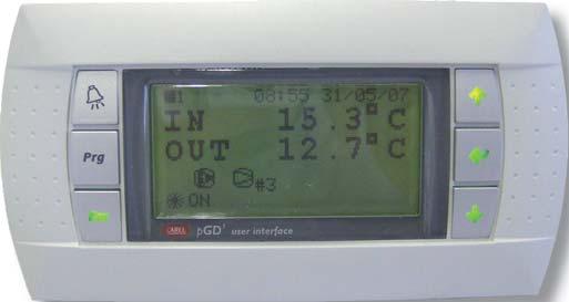
34 4 USER INTERFACE The user interface adopted, PGD1, comprises an LCD display (8 rows x 22 columns) and 6 keys. From here the user can carry out all program-related operations, view the status of the unit at all times and edit parameters. 4.1 DESCRIPTION OF KEYBOARD The 6 keys and their respective functions are described in the table below. Key ALARM Description Press the ALARM key to reset alarms. When there is an alarm, it will light up. PROGRAM Press PRG to access the main menu. ESC Press ESC to move up to a higher level in the menu. UP Press UP to go to the next screen or increase the value of a parameter.. ENTER Press ENTER to go into the fields of parameters to be edited and to confirm changes. DOWN Press DOWN to go to the previous screen or decrease the value of a parameter. 4.2 SWITCHING ON THE UNIT AND SELECTING THE OPERATING MODE The steps necessary for switching on the unit (and selecting the mode) are the following: press to go to the main screen main U1 08:00 01/01/00 IN 12.0 C OUT 12.5 C OFF by keyboard keep the key pressed down for at least 3 seconds. The following screen will appear: on_unit Switch On unit ->cooling PRG : Confirm ESC : Cancel AQUA 4 CMA-1405-E
35 if the chiller is a Heat Pump model you can move the cursor to the operating mode by pressing and, using the arrows, select between cooling and heating. Press to confirm unit ON in the selected mode or to cancel the operation. Once you have made the selection, the display will return to the main screen. 4.3 SWITCHING OFF OF THE UNIT The steps necessary for switching off the unit are the following: press to go to the main screen main U1 08:00 01/01/00 IN 12.0 C OUT 12.5 C ON keep the key pressed down for at least 3 seconds. The following screen will appear: off_unit Switch Off unit? PRG : Confirm ESC : Cancel Press to confirm unit OFF or to cancel the operation. Once you have made the selection, the display will return to the main screen. 4.4 GENERAL DESCRIPTION OF MENUS The key can be used as needed to exit submenus and also permits the user to view the main information concerning chiller operation. From the main screen: main U1 08:00 01/01/00 IN 12.0 C OUT 12.5 C ON press to view the menu; using the arrow keys select the submenu concerned and press to enter it. Below is a list of the items included in the main menu and the type of parameters contained in each. Chiller Status This menu provides general information regarding the status of the unit and its main components. It is in turn divided into 3 submenu items: Devices: status of compressors, heating element, fans, pumps Electronic valve: status of the electronic valves and reading of sensors LAN: indication of any units connected to the LAN AQUA 4 CMA-1405-E
36 Inputs/Outputs Menu From this menu it is possible to view, and if necessary override, the status of all controller inputs and outputs. The submenu items are: I/O status: the statuses of the analog and digital inputs and analog and digital outputs are displayed in order. I/O override: if enabled from the maintenance menu, all inputs and outputs read and governed by the pco can be manually controlled. Setpoint Menu Management of fixed setpoint and variable setpoint. User Menu From this menu, password protected (100), it is possible to configure the main chiller control logics. This menu is in turn divided into: Setpoints and Parameters: control logic, setpoint management, compressor rotation and any configurable digital inputs. LAN and Supervision : enabling of On/Off logics and summer/winter changeovers; LAN logic and selection of parameters for serial communication Alarms: configuration of the digital alarm output and definition of serious alarms Clock: clock setting and programming of unit ON/OFF time zones (only where a clock card is installed) Maintenance Menu Password protected (password not provided), this menu is divided into: Manual Control: enabling of manual override of the microcontroller inputs and outputs (managed thereafter from the I/O menu) Parameters: sensor offset and password change Running hours: run time of the main chiller devices and management of the related alarms History: list of past alarms and erasure of history Manufacturer's Menu Password protected (password not provided), this menu is divided into: Unit Configuration: parameters that define the type of unit and the devices making it up Parameters: setting of essential operating parameters (condensation control, defrost function ) Alarms: configuration of alarms Carel EXV Drivers: settings of drivers for the control of electronic valves Initialisation and password: restoring of default parameters and password definition Info Menu It contains the version, code and date of the software used; from here you can also set the display language Password As indicated above, the User, Maintenance and Manufacturer's menus require entry of a password in order to gain access; it was decided to give only the User password in this manual. Entry of the password enables access at the level concerned for a certain amount of time, so that it will not be necessary to re-enter the password until this time elapses; the password also provides access to lower level menus, according to priority as shown below: 1. Manufacturer's Menu 2. Maintenance Menu 3. User Menu The passwords can subsequently be changed respectively from: 1. Manufacturer's menu Initialisation and Password W2 2. Maintenance menu Parameters N5 3. User menu Setpoints and parameters Hi The duration of access is a single parameter which, for the sake of convenience, has been included in all three of the screens indicated above. If this value is changed from one screen, the change will automatically be shown in the others as well. AQUA 4 CMA-1405-E
37 4.5 USER INTERFACE CONNECTION Physical connection Local display Local display Panel-mounted Display cable: telephone cable pco microprocessor Unit o a telephone cable (for the connection between pco and Local Display) Local and remote display (within 50m) Local display Panel-mounted TCONN connector (necessary only if both a local and remote display are present) Remote display cable: telephone cable. Remote display Wall-mounted pco microprocessor Unit o 1 T-connector (TCONN6 with jumpers J14 and J15 in position 1-2) o 3 telephone cables (for the connections between pco1-t-connector; T-connector-Local Display; T- connector-remote Display) Local and remote remote display (over 50m) Local display Panel-mounted Remote display cable: telephone cable. max 200m Remote display Wall-mounted pco microprocessor Cable: 6 wires, w/ RJ11 connectors. Unità NOTE: The cable is different from a standard telephone cable because the connectors are reversed. o 2 T-connectors (TCONN6 with jumpers J14 and J15 in position 1-2) AQUA 4 CMA-1405-E
38 o 3 telephone cables (for the connections between pco1-t-connector; T-connector-Local Display; T- connector-remote Display) o Shielded 3 twisted pair cable ( to connect the two T-connectors) Software configuration In order for the local display terminal and, where present, the remote display terminal to work correctly, the addresses must be set as shown in the table: List of Addresses pco address Display Address Unit 1 25 Remote Display - 32 For the configuration procedure, see section ADDRESS SETTINGS 5.1 SETTING THE DISPLAY ADDRESS To set the address of the display terminal, carry out the following steps: Press the Up, Enter and Down keys together until the following screen appears: Display address setting...:00 Press UP or DOWN to set the address Press ENTER to save and exit the procedure 5.2 SETTING THE PCO ADDRESS (PCOXS OR PCO1) To set the address of the pco controller, carry out the following steps: To the pco1 connect a display terminal with an address configured as 0 Switch on the pco1 controller, simultaneously pressing the ALARM and UP keys on the terminal until the following screen appears plan address: 0 UP: increase DOWN: decrease ENTER: save & exit Press UP or DOWN to set the address according to the table above Press ENTER to save and exit the procedure 5.3 MICROPROCESSOR/DISPLAY CONFIGURATION Once the display and pco addresses have been set (values indicated in the tables provided), if the display does not show anything it means that the pco controller needs to be set so that it can communicate with the display terminal. Follow the procedure indicated below. Press UP + ENTER + DOWN together for 5 seconds; the following screen will appear: Display address setting...:25 I/O Board address:-- AQUA 4 CMA-1405-E
39 Press ENTER to move to the field at the bottom and use the arrows to select the address of the pco controller connected to the display Press ENTER to confirm; the following screen will appear: Terminal config Press ENTER to continue Press ENTER; the following screen will appear: Microprocessor address P:01 Adr Priv/Shared Trm1 25 Pr Trm2 32 Sh Trm3 None -- Ok?No Display mode: Pr = Private, Sh = Shared Display addresses Change from No to Yes to confirm changes From this screen you must set the address and operating mode of the display (terminal) connected to the microprocessor. Note that up to 3 displays (terminals Tmr1-2-3) can be connected to a pco. Press ENTER to move the cursor into the fields and UP and DOWN to change the value of the terminals concerned, so that they match those of the connected displays The display mode can be: o o Private : if the display terminal is defined as private, it can communicate with only one microprocessor. Shared : if the display terminal is shared (in the case of units connected in a LAN), it can communicate with a number of microprocessors; in this case you can switch from one to another by keeping the ESC key pressed and repeatedly pressing the DOWN key. To confirm the changes, change the parameter near Ok? to YES. AQUA 4 CMA-1405-E
40 6 SCREENS The main information screens of the application, divided into the different menus, are shown below. Appearing in the top right-hand corner is a code identifying the individual screen (except the Main menu screens). 6.1 MAIN main U1 08:00 01/01/00 IN 12.0 C OUT 12.5 C OFF main_2 CIRCUIT 1 Water IN : 00.0 C Water OUT : 00.0 C Cond.press: 00.0 bar Cond.temp : 00.0 C main_2b CIRCUIT 1 Water IN : 00.0 C Water OUT : 00.0 C Cond.temp : 00.0 C main_3 CIRCUIT 2 Water IN : 00.0 C Water OUT : 00.0 C Cond.press: 00.0 bar Cond.temp : 00.0 C main_4 DEFROST Circuit 1: no Circuit 2: no main_5 FREECOOLING Ext.Temp : 00.0 C Status : off Coil partial.: no 3 ways valve: closed Main screen that shows the inlet water, outlet water (average in units with 2 evaporators), unit status and any active components (indicated by means of icons). - pump 1 - pump 2 - compressors (with an indication of how many are running) - fans - heating elements Main readings relative to circuit 1: - Inlet water - Outlet water - Condensation Pressure (or Evaporation in heat pump models) - Equivalent (dewpoint) Main readings relative to circuit 1 (in the case of water/water units): - Inlet water - Outlet water - Condenser Temperature Main readings relative to circuit 2 ( in the case of Heat Pump units) Indication of whether the circuit is undergoing a defrost cycle (in the case of Freecooling units) - Outdoor Temperature - Freecooling Status - Coil capacity control - 3-way valve AQUA 4 CMA-1405-E
41 6.2 CHILLER STATUS Chiller Status Devices t_sm_disp_01 COMPRESSORS A1 C1:off C4:off C8:-- C2:off C5:-- C7:-- C3:off C6:-- Prev.HP on circ1: - Prev.HP on circ2: - t_sm_disp_02 PUMPS A2 Pump 1: off Pump 2: off t_sm_disp_03 HEATERS A3 Heater : off t_sm_disp_04 FANS A4 Fans 1: off 000.0% Fans 2: off 000.0% t_sm_disp_05 4 WAYS VALVE A5 Valve C1->Not Excited Valve C2->Not Excited t_sm_disp_06 3 WAYS VALVE A6 ->closed Compressor status. Indication of whether high pressure prevention function is active in the circuit Pump status Antifreeze heating element output status Fan status and percentage of operating capacity used, where applicable ( in the case of Heat Pump units) 4-way valve status NB: 4-way valve logic config. in Manufacturer's menu Parameters Tc (in the case of Freecooling units) 3-way valve status AQUA 4 CMA-1405-E
42 t_sm_disp_07 COIL PARTIAL. A7 SOLENOID ->not active t_sm_disp_08 EXTERN MODEM A8 Status: Modem on stand-by. Dialled Number:0 (in the case of Freecooling units) Status of capacity control solenoid valve (in the case of GSM supervision protocol) Modem status Chiller Status - Valve d_inout1_d1 DRIVER 1 B1 Gas : --- Mode :Cool EEV :AUTO Valve position:0000 Power request: 000% d_inout2_d1 DRIVER 1 B2 SuperHeat : C Suction T. : C Evap.temp. : C Evap.press.: 00.0barg Cond.temp. : C d_inout4_d1 DRIVER 1 B3 PROTECTION LowSH:No HtCond:No LOP: No MOP: No Electronic Valve Status d_io_drv_vers DRIVERS B7 Drv1 Version Drv2 Version Electronic valve driver versions AQUA 4 CMA-1405-E
43 6.2.3 Chiller Status LAN t_sm_lan_01 plan C1 Unit 1:On Line Alone Unit 2:Off Line Unit 3:Off Line Unit 4:Off Line t_sm_lan_02 C2 Reference T.IN for control logic 00.0 C Indication of which units are physically connected to plan - On Line : connected - Off Line : disconnected Indication of enabled LAN logic, where applicable - (Stand) Alone: LAN logic not active - Master : LAN logic active in unit 1 - Slave : LAN logic active in a unit other than number 1 Inlet water used by the Master unit for the purpose of the control logic. If the Master unit pump is off, this value will be the average of the other units connected. t_sm_lan_03 C3 Running mode active for LAN - Cooling If the Master unit is off it indicates the active operating mode, in which the slave units will start up 6.3 INPUTS/OUTPUTS MENU Inputs/Outputs Menu - I/O Status t_io_stato_01 ANALOG INPUTS D1 B1: 00.0bar B2: 00.0 C B3: 00.0 C B4: 00.0 C It displays the status of the analog inputs (value resulting from an override, where present) Inputs/Outputs Menu - I/O Override t_io_forz_01 ANALOG INPUTS E1 Override B1: AUTO 00.0bar B2: AUTO 00.0 C B3: AUTO 00.0 C B4: AUTO 00.0 C t_io_forz_99 Override Not Enabled Indication of the value assigned to the analog input and the value applied in the case of an override - AUTO : analog input not overridden - MAN : analog input overridden with the value on the right If the override function has not been enabled from the Maintenance menu Manual Control M1, this screen will be displayed AQUA 4 CMA-1405-E
44 6.4 SETPOINT MENU t_setpoint_1 Active F1 Setpoint : 00.0 C - secondary : - - time zones : - - remote adjust: - - compensation : - - bounded : - Active setpoint used by the control logic and any setpoint adjustment logics that may be active 6.5 MAINTENANCE MENU Running hours m_mant_oref_3 Running hours P3 Compressor 1 Hours: Reset: no m_mant_oref_13 Running hours Pd Pump 1 Hours: h Reset: no History m_mant_sto_01 R1 Press ALARM to view the Alarm History Running hours of compressor 1, may be reset Running hours of pump 1, may be reset From this screen, pressing the ALARM key will call up the alarm history; while pressing the arrow will take you to the next screen of this menu m_mant_sto_02 R2 Erase history database? no 6.6 MANUFACTURER'S MENU Initialisation and password m_cost_iniz_01 W1 Reset all the parameters to the default values? no Screen for restoring the default parameters (indicated in this manual in section 7) AQUA 4 CMA-1405-E
45 6.7 INFO MENU t_info_1 - INFO - X1 V: ChillerScroll 1.00 C: D: 05/2007 Language: German t_info_2 X2 CONFIGURATION WORD Software version installed Code of the installed software Date of the installed software Language selection Parameter resulting from the combination of the main parameters set in the software application. 7 APPLICATION SETTING PARAMETERS 7.1 SETPOINT MENU Screen Par. Description Default Range UOM Setpoint F2 1 Cooling Setpoint 12.0 H7(1) / H7(2) C 2 Heating Setpoint 40.0 H8(1) / H8(2) C F3 1 Secondary Cooling Setpoint 12.0 H7(1) / H7(2) C 2 Secondary Heating Setpoint 40.0 H8(1) / H8(2) C F4 1 Setpoint Inside Time zone 12.0 H7(1) / H7(2) C 2 Setpoint Outside Time zone 12.0 H7(1) / H7(2) C F5 1 Setpoint Inside Time zone- Cooling 12.0 H7(1) / H7(2) C 2 Setpoint Outside Time zone - Cooling 12.0 H7(1) / H7(2) C F6 1 Setpoint Inside Time zone - Heating 40.0 H8(1) / H8(2) C 2 Setpoint Outside Time zone - Heating 40.0 H8(1) / H8(2) C 1 Start of time zone - hour (Monday) 7 0 / 23 h 2 Start of time zone - minutes (Monday) 00 0 / 59 min. F7 3 End of time zone - hour (Monday) 22 0 / 23 h 4 End of time zone - minutes (Monday) 00 0 / 59 min... the same applies for the other days 1 Enabling of setpoint adjustment via analog input 0 0/1 F9 2 Adjustment with min. value of analog input / 99.9 C 3 Adjustment with max. value of analog input / 99.9 C 1 Compensation Setpoint - Cooling / 99.9 C Fa 2 Compensation Differential - Cooling / 10.0 C 3 Maximum Compensation - Cooling / 10.0 C 1 Compensation Setpoint - Heating / 99.9 C Fb 2 Compensation Differential - Heating / 10.0 C 3 Maximum Compensation - Heating / 10.0 C AQUA 4 CMA-1405-E
46 7.2 USER MENU User - Setpoints and Parameters Screen Par. Description Default Range UOM H1 User 1 DIN 14 Configuration not present not present/ serious alarm/ secondary setpoint/ fan 2nd series 2 Reset serious alarm from DIn auto auto / man not present/ serious H2 1 DIN 6 Configuration not present alarm/ secondary setpoint 2 Reset serious alarm from DIn auto auto / man proportional / 1 Type of control proportional prop.+int. H3 2 Integral Time / 9999 s 3 Percentage of Hysteresis / 100 % none / by time H4 1 Automatic Setpoint Adjustment none zones / via digital input H5 1 Setpoint compensation in cooling mode no no / yes 2 Setpoint compensation in heating mode no no / yes H6 1 Enable dehumidification setpoint no no / yes H7 1 Cooling setpoint lower limit / 99.9 C 2 Cooling setpoint upper limit / 99.9 C H8 1 Heating setpoint lower limit / 99.9 C 2 Heating setpoint upper limit / 99.9 C H9 1 Setpoint Differential in cooling mode / 10.0 C 2 Setpoint Differential in heating mode / 10.0 C 1 Pump Rotation auto man / auto Ha 2 Rotation Period 6 0 / 999 h9 3 Pump Sequence pump 1 pump 1/ pump 2 Hb 1 Compressor Rotation FIFO LIFO / FIFO 2 Circuit Rotation balanced non-bal. / balanced He 1 Freecooling Enabling Delta / 9.9 C 2 Freecooling Enabling Differential / 3.0 C proportional / 1 Type of fan control in FC proportional Hf prop.+int. 2 Integral Time / 9999 s Hg 1 Deviation from setpoint for min. fan speed in FC / Hg(2) C 2 Deviation from setpoint for max. fan speed in FC -3 Hg(1) / 2.0 C Hh 1 Cooling icon configuration snowflake snowflake / sun Hi 1 User Password / Duration of Login w/ Password 5 0 / User - LAN and Supervision Screen Par. Description Default Range UOM User 1 Enable On/Off from keyboard yes no / yes J1 2 Enable On/Off by remote contact yes no / yes 3 Enable On/Off via supervisor no no / yes 4 Enable On/Off by time zones no no / yes J2 1 Enable summer/winter changeover via remote contact yes no / yes 2 Enable summer/winter changeover via supervisor no no / yes 1 Enable LAN logic no no / yes J3 Cascade / Step 2 Unit On/Off logic in LAN Cascade Control none / standard / 1 Unit Rotation Logic in LAN standard J4 with standby 2 Unit rotation time in LAN 24 0 / 9999 h J5 1 Delay in next start-up of compressors 2 0 / 999 s 1 Communication speed / 2400 / 4800 / 9600 / bps J6 2 Identification number 1 1/200 3 Communication protocol Carel Carel / Modbus/ Lon / Rs232 / GSM AQUA 4 CMA-1405-E
47 7.2.3 User - Alarms Screen Par. Description Default Range UOM User all / serious / not 1 Type of alarm digital output all K1 serious 2 alarm digital output logic n.o. n.o. / n.c. K2 alarm configuration Serious/Not Serious see alarms table Serious/Not Serious K3 alarm configuration Serious/Not Serious see alarms table Serious/Not Serious User - Clock Screen Par. Description Default Range UOM User 1 Start of first interval of TIME ZONE 1 - hour 8 0 / 23 h 2 Start of first interval of TIME ZONE 1 - minutes 0 0 / 59 min. 3 End of first interval of TIME ZONE 1 - hour 12 0 / 23 h 4 End of first interval of TIME ZONE 1 - minutes 0 0 / 59 min. 5 Start of second interval of TIME ZONE 1 - hour 13 0 / 23 h L2 6 Start of second interval of TIME ZONE 1 - minutes 0 0 / 59 min. 7 End of second interval of TIME ZONE 1 - hour 20 0 / 23 h 8 End of second interval of TIME ZONE 1 - minutes 0 0 / 59 min. 9 Start of TIME ZONE 2 - hour 8 0 / 23 h 10 Start of TIME ZONE 2 - minutes 0 0 / 59 min. 11 End of TIME ZONE 2 - hour 18 0 / 23 h 12 End of TIME ZONE 2 - minutes 0 0 / 59 min. 7.3 MAINTENANCE MENU Maintenance Manual Control Screen Par. Description Default Range UOM Maintenance 1 Enable D.IN from keyboard no no / yes M1 2 Enable A.IN from keyboard no no / yes 3 Enable D.OUT from keyboard no no / yes 4 Enable A.OUT from keyboard no no / yes M4 1 EEV mode circuit 1 auto auto / man 2 Steps demanded of EEV circuit /.. M6 1 EEV mode circuit 2 auto auto / man 2 Steps demanded of EEV circuit / Maintenance Running hours Screen Par. Description Default Range UOM Maintenance P1 1 Enable alarm to signal when compressors exceed run time threshold yes no / yes 2 Compressor run time threshold / h Pb 1 Enable alarm to signal when pumps exceed run time threshold yes no / yes 2 Pump run time threshold / h Maintenance Parameters Screen Par. Description Default Range UOM Maintenance 1 Offset sensor B1 pcoxs / 9.9 N1 2 Offset sensor B2 pcoxs / Offset sensor B3 pcoxs / Offset sensor B4 pcoxs / Offset sensor B1 pco / Offset sensor B2 pco / Offset sensor B3 pco / 9.9 N2 4 Offset sensor B4 pco / Offset sensor B5 pco / Offset sensor B6 pco / Offset sensor B7 pco / Offset sensor B8 pco / Offset sensor S1 EVD Circuit / 9.9 N3 2 Offset sensor S2 EVD Circuit / Offset sensor S3 EVD Circuit / 9.9 AQUA 4 CMA-1405-E
48 N4 N5 1 Offset sensor S1 EVD Circuit / Offset sensor S2 EVD Circuit / Offset sensor S3 EVD Circuit / Maintenance Password xxxx 0 / Duration of Login w/ Password 5 0 / MANUFACTURER'S MENU Manufacturer - Unit Config. Screen Par. Description Default Range UOM Manufacturer 1 Unit Type water/air water/water ; water/air 2 Configuration cooling only cooling only / heat pump S1 R22 / R134a / R404A / R407C / 3 Gas R407C R410A / R507 / R290 / R600 / R600a / R717 / R744 1 Number of circuits 1 1 / 2 S2 2 Compressors Circuit / 2 / 3 / 4 3 Compressors Circuit / 2 / 3 / 4 4 Pumps 0 0 / 1 / 2 S 1 Evaporator single single / separate S4 1 Condenser single single / separate S4a 1 Pressure sensor installed yes no / yes 1 Type of Condensation/Evaporation Control modulating no / on-off / modulating S5 2 Fan series 1 1 / 2 3 Fan series 1 control output pwm 0-10V / pwm 4 Fan series 2 control output pwm 0-10V / pwm transducer transd 4-20mA / 1 Pressure sensor configuration 4-20mA ratiometric S6 2 Lower value / bars 3 Upper value / bars 1 Configuration of sensor B2 not present not present / rem.set.corr. / outdoor temp. sensor S7 NTC sensor / 0/1V 2 B2 sensor type sensor / 0/5V NTC sensor / 0-20mA sensor sensor / 4-20mA sensor S8 1 Configuration of sensor B3 Remote Setpoint Adjustment Remote Setp. Adjustment / Outdoor Temp. S9 1 Outdoor sensor installed no no / yes Sa 1 Heating element installed no no / yes Sb without w/o Slew Rate / 1 Configuration of analog outputs Y1-Y2 Slew Rate w/slew Rate FCS or CONV0-2 Configuration of analog outputs Y3-Y4 MCHRTF 10A0 / MCHRTF 1 Config. of Y1-Y2 Duty Cycle / 10.0 V/ s Sc 2 Config. of Y1-Y2 Period / 10.0 V/ s Sd 1 Config. of Y1-Y2 minimum voltage / 9.9 V 2 Config. of Y1-Y2 maximum voltage Sd(1) / Sd(3) V 3 Config. of Y1-Y2 maximum voltage Sd(2) / 10.0 V Se 1 Minimum Config. Triac Y3-Y / % 2 Maximum Config. Triac Y3-Y / % Sf 3 Config. WD Triac Y3-Y / 10.0 ms 1 pcoe expansion installed no no / yes Sg Sh Yes 1 Driver EVD / 2 2 EVD400 Driver Type tlan plan / tlan 1 EVD400 Sensor Type NTC-P(rat) 2 PID Control direct direct / reverse 1 Valve Type CAREL E2V.. 2 Coil Enabled no no / yes AQUA 4 CMA-1405-E
49 7.4.2 Manufacturer Parameters Screen Par. Description Default Range UOM Manufacturer T1 1 Minimum compressor off time / 9999 s 2 Minimum compressor on time 60 0 / 9999 s T2 1 Time lapse between start-up of different compressors / 9999 s 2 Time lapse between two start-ups of same compressor / 9999 s 1 Enable antifreeze heating element no no / yes T3 2 Antifreeze heating element control setpoint / 99.9 C 3 Antifreeze heating element control differential; / 99.9 C T4 1 Enable D.In filter no no / yes 2 Filter delay time 5 0 / 9 s T5 1 Condensation Control - Setpoint / 30.0 bars 2 Condensation Control - Differential / 20.0 bars none / in advance / 1 Condensation - Fans On Override none speed-up T6 2 Condensation - Duration of Override 10 0 / 999 s 3 Condensation - Override Speed / % T7 1 Condensation - Speed Alarm / % T8 1 Evaporation Control - Setpoint / 45.0 bars 2 Evaporation Control - Differential / 45.0 bars 1 Evaporation - Fans On Override none none / in advance / speed-up T9 2 Evaporation - Duration of Override 10 0 / 999 s 3 Evaporation - Override Speed / % Ta 1 Evaporation - Speed Alarm / % Tb 1 Advance/delay in pump on/off switching 20 0 / 999 s Tc Td Te 1 Cycle-reversing valve in heat pump energised energised / non-energised 2 ON delay in valve rotation 10 0 / 99 s 3 Enable ON delay no no / yes 1 Defrost Logic Press. Pressure threshold / threshold Temp. change 2 Defrost Mode simultaneous separate simultaneous / 3 Max. duration of defrost cycle / 9999 s 4 Minimum time lapse between two defrost cycles 30 0 / 500 min. 1 Pressure threshold for starting defrost cycle / 99.9 bars 2 Pressure threshold for stopping defrost cycle 19.0 Te(1) / 99.9 bars 3 Defrost start delay time / 9999 s 1 Temperature change for starting defrost cycle / 99.9 C Tf 2 Pressure threshold for stopping defrost cycle / 99.9 bars Tf 1 Max. evap. temp. for starting defrost cycle / 99.9 C Tf 1 Delay for memorisation of max. evaporation temp / 999 s Tg 1 Enable compres. stop when defrosting begins no no / yes 2 Duration of compres. stop at beginning of defrost cycle 30 2 / 999 s Th 1 Enable compres. stop when defrosting ends no no / yes 2 Duration of compres. stop at end of defrost cycle 30 2 / 999 s 1 Enable fans ON at end of defrost cycle no no / yes Ti 2 Fan speed at end of defrost cycle / % 3 Max. fan run time at end of defrost cycle 30 2 / 999 s 4 Max. pressure while fans running at end of defrost cycle 21.5 Te(2) or Tf(2) / 99.9 bars Tj 1 Delay compres. start-up during defrost cycle 5 1 / 999 s Tk 1 Enable Freecooling no no / yes Tm 1 Compr. off time at start of Freecooling / 999 s Tn To 1 Outlet water T limit in Freecooling mode 7.0 / 99.9 C 2 Differential for reactivation of Freecooling / 5.0 C 1 Freecooling valve run time / 500 s 2 Enable Freecooling valve rotation yes no / yes 3 Freecooling valve rotation threshold / 720 hours Tp 1 Freecooling valve override time 50 0 / 180 s 2 Adjust Freecooling valve counter / 4000 s Tq 1 Enable coil capacity control solenoid valve yes no / yes 2 Capacity control solenoid valve logic n.o. n.o. / n.c. Tr 1 HP prevention Capacity reduction inhibition setpoint / 25.0 bars 2 HP prevention Capacity reduction inhibition differential / 10.0 bars Ts 1 LP prevention Capacity reduction setpoint / 20.0 bars 2 LP prevention Capacity reduction differential / 10.0 bars Tt 1 Enable capacity control solenoid valve override yes no / yes Tu 1 Compr. OFF time with valve open due to override / 999 min. 2 Duration of valve override for compr. OFF 10 0 / 999 min. Tv 1 Compr. ON time in FC mode with valve open due to override 60 0 / 999 min. 2 Duration of valve override for compr. ON in FC mode 5 0 / 999 min. Tw 1 Enable low load logic no no / yes AQUA 4 CMA-1405-E
50 2 Low load logic application mode Chiller Chiller / Heat Pump / Chiller + Heat Pump 3 Max compr. On for low load definition 120 T1(2) / 999 s Tx 1 Differential in low load - Chiller / 10.0 C 2 Differential in low load Heat Pump / 10.0 C Ty 1 Duration of ON enabling by Master unit 5 0 / 999 s 1 Enable compr. inhibition on Text Heat Pump no no / yes Tz 2 Set compr. inhibition on Text Heat Pump / 99.0 C 3 Compr. inhibition differential on Text Heat Pump / 9.9 C Manufacturer Alarms Screen Par. Description Default Range UOM Manufacturer U1 1 Enable sensor fault alarm yes no / yes 2 Sensor fault alarm delay 10 0 / 9999 s 1 Enable sensor B1 fault alarm pcoxs yes no / yes U2 2 Enable sensor B2 fault alarm pcoxs yes no / yes 3 Enable sensor B3 fault alarm pcoxs yes no / yes 4 Enable sensor B4 fault alarm pcoxs yes no / yes 1 Enable sensor B1 fault alarm pco1 yes no / yes 2 Enable sensor B2 fault alarm pco1 yes no / yes 3 Enable sensor B3 fault alarm pco1 no no / yes U3 4 Enable sensor B4 fault alarm pco1 yes no / yes 5 Enable sensor B5 fault alarm pco1 yes no / yes 6 Enable sensor B6 fault alarm pco1 no no / yes 7 Enable sensor B7 fault alarm pco1 no no / yes 8 Enable sensor B8 fault alarm pco1 no no / yes U5 1 Enable clock alarm no no / yes 1 Enable pump thermal alarm yes no / yes U6 2 Pump thermal alarm reset man auto / man 3 Pump thermal alarm delay 0 0 / 999 s 1 Enable flow alarm yes no / yes U7 2 Flow alarm reset man auto / man 3 Flow alarm delay at start-up 20 0 / 999 s 4 Flow alarm delay during operation 5 0 / 999 s 1 Enable high pressure alarm by pressure switch yes no / yes U9 2 High pressure alarm reset man auto / man 3 High pressure alarm delay 0 0 / 999 s 1 Enable low pressure alarm by pressure switch yes no / yes Ua 2 Low pressure alarm reset man auto / man 3 Low pressure alarm delay at start-up / 999 s 4 Low pressure alarm delay during operation / 999 s Ub 1 Disable low pressure alarm in heat pump mode no no / yes Uc 1 Delay time of a second manually reset low pressure alarm 60 0 / 540 min. 2 Enable second manually reset low pressure alarm no no / yes 1 Enable high pressure alarm triggered by sensor yes no / yes 2 Sensor-triggered high pressure alarm reset man auto / man Ud 3 Sensor-triggered high pressure alarm setpoint / 99.9 bars 4 Sensor-triggered high pressure alarm differential / 99.9 bars 5 Sensor-triggered high pressure alarm delay 1 1 / 999 s 1 High pressure alarm prevention yes no / yes Ue 2 High pressure alarm prevention setpoint / 99.9 bars 3 High pressure alarm prevention diff / 99.9 bars 4 High pressure alarm prevention delay 0 0 / 999 s Uf 1 Attempts to prevent high pressure alarm with single compressor circuit 3 1 / 99 1 Enable low pressure alarm triggered by sensor no no / yes 2 Sensor-triggered low pressure alarm reset man auto / man Ug 3 Sensor-triggered low pressure alarm setpoint / 99.9 bars 4 Sensor-triggered low pressure alarm differential / 99.9 bars 5 Low pressure alarm delay at start-up 60 0 / 999 s 6 Low pressure alarm delay during operation 0 0 / 999 s 1 Enable compressor thermal alarm yes no / yes Uh 2 Compressor thermal alarm reset man auto / man 3 Compressor thermal alarm delay at start-up 10 0 / 999 s 4 Compressor thermal alarm delay during operation 10 0 / 999 s 1 Enable fan thermal alarm yes no / yes Ui 2 Fan thermal alarm reset man auto / man 3 Fan thermal alarm delay 0 0 / 999 s 1 Enable antifreeze alarm yes no / yes Uj 2 Antifreeze alarm reset man auto / man 3 Antifreeze alarm setpoint / 99.9 C 4 Antifreeze alarm differential / 99.9 C AQUA 4 CMA-1405-E
51 5 Antifreeze alarm delay 0 0 / 999 s Uk 1 Enable phase direction alarm yes no / yes 1 Enable Freecooling fault alarm no no / yes Um 2 Freecooling fault alarm reset auto auto / man 3 Freecooling fault alarm delay / 600 s 4 Freecooling fault alarm differential / 2.0 C Un 1 Threshold value of (Tin-Tfc) beyond which, in the absence of freecooling, a fault will be signalled / 3.0 C 2 Threshold value of Tfc-Tin below which, if the freecooling function is on, a fault will be signalled / 2.0 C Uo 1 Minimum fan operating capacity for enabling freecooling fault alarm / % Manufacturer Carel EVD Screen Par. Description Default Range UOM Manufacturer 1 Minimum steps Custom Valve 0 0 / 8100 V1 2 Maximum steps Custom Valve 0 0 / Closing steps Custom Valve 0 0 / 8100 V2 1 Extra Opening Custom Valve no no / yes 2 Extra Closing Custom Valve no no / yes 1 Mov. current 0 0 / 1000 ma V3 2 Stat. current 0 0 / 1000 ma 3 Frequency / 501 Hz 4 Duty cycle 0 0 / 100 % V4 1 EEV position with 0% capacity demanded 30 V5 1 Minimum value of EVD sensor S / 99.9 barg 2 Maximum value of EVD sensor S / 99.9 barg 1 Low superheat alarm delay / 3600 s 2 High superheat alarm delay 20 0 / 500 min. V6 3 LOP alarm delay / 3600 s 4 MOP alarm delay 0 0 / 3600 s 5 Sensor error alarm delay 10 0 / 999 s 1 Percentage of EEV opening Chiller Mode 0 0 / 100 % V8 2 Proportional constant Chiller Mode / Integration time Chiller Mode 0 0 / 999 s V9 1 Superheati setpoint Chiller Mode Driver / 50.0 C 2 Low superheat Chiller Mode Driver / 21.0 C Va 1 Superheat setpoint Chiller Mode Driver / 50.0 C 2 Low superheat Chiller Mode Driver / 21.0 C 1 Percentage of EEV opening Heat Pump Mode 0 0 / 100 % Vb 2 Proportional constant Heat Pump Mode / Integration time Heat Pump Mode 0 0 / 999 s Vc 1 Superheat setpoint Heat Pump Mode Driver / 50.0 C 2 Low superheat Heat Pump Mode Driver / 21.0 C Vd 1 Superheat setpoint Heat Pump Mode Driver / 50.0 C 2 Low superheat Heat Pump Mode Driver / 21.0 C 1 Percentage of EEV opening Defrost Mode 0 0 / 100 % Ve 2 Proportional constant Defrost mode / Integration time Defrost mode 0 0 / 999 s Vf 1 Superheat setpoint Defrost Mode Driver / 50.0 C 2 Low superheat Defrost Mode Driver / 21.0 C Vg 1 Superheat setpoint Defrost Mode Driver / 50.0 C 2 Low superheat Defrost Mode Driver / 21.0 C 1 Dead band - Superheating / 9.9 C Vh 2 Derivative time - Superheating / 99.9 s 3 Integral time low superheat / 30.0 s 4 Integral time LOP s Vi 1 Integral time MOP s 2 MOP start-up delay 0 0 / 500 s Vj 1 Dynamic proportional control no no / yes 2 EEV block control 0 0 / 999 s Vk 1 High condensation temp. alarm / 99.9 C 2 Integral time condensation temp. 0 0 / 25.5 s Vn 1 Percentage of opening at start-up 60 0 / 100 % Vo 1 Compressors SCREW Not Selected / RECIPROCATING / SCREW / SCROLL / CABINET FLOODED / CABINET AQUA 4 CMA-1405-E
52 Vp Vq 2 Capacity control NO / STEPS 1 Evaporator in cooling mode PLATES 2 Evaporator in heating mode FINS FAST Not selected / NO- STEPS / SLOW CONTINUOUS / FAST CONTINUOUS Not Selected / PLATES / TUBE BUNDLE / FINS FAST / FINS SLOW Not Selected/ PLATES/ TUBE BUNDLE/ FINS FAST / FINS SLOW 1 Min. saturation temp. in cooling mode / 50.0 C 2 Min. saturation temp. in heating mode / 50.0 C 3 Min. saturation temp. in defrost mode / 50.0 C 1 Max. saturation temp. in cooling mode / 90.0 C Vr 2 Max. saturation temp. in heating mode / 90.0 C 3 Max. saturation temp. in defrost mode / 90.0 C Vs 1 High superheat alarm threshold 0 0 / 1000 C AQUA 4 CMA-1405-E
![8 CONTROL SYSTEM ARCHITECTURE 8.1 MICROPROCESSOR LAYOUT 8.1.1 pco1 Description of connectors 1. power supply connection [G(+), G0(-)]; 2. 2A slow-blow fuse, 250 Vac (T2 A); 3.](/docs-images/85/92894639/images/53-0.jpg "NTC universal analog inputs, 0/1 V, 0/5 V, 0/20 ma, 4/20 ma; 4. ON/OFF and NTC passive analog inputs; 5. NTC passive analog inputs; 6. Yellow power ON LED and 3 indicator LEDs; 7.")
53 8 CONTROL SYSTEM ARCHITECTURE 8.1 MICROPROCESSOR LAYOUT pco1 Description of connectors 1. power supply connection [G(+), G0(-)]; 2. 2A slow-blow fuse, 250 Vac (T2 A); 3. NTC universal analog inputs, 0/1 V, 0/5 V, 0/20 ma, 4/20 ma; 4. ON/OFF and NTC passive analog inputs; 5. NTC passive analog inputs; 6. Yellow power ON LED and 3 indicator LEDs; 7. analog outputs 0/10 V and PWM current outputs; Vac/Vdc digital inputs; Vac or 24 Vac/Vdc digital inputs; 10. connector with Vref for 5V power supply to sensors and V Term for power supply to display terminal; 11. connector for all standard display terminals in pco controller series and for downloading application program; 12. plan local network connector; 13. connector for connection to the programming key; 14. digital outputs to relay; 15. flap for selecting the type of analog inputs; 16. flap for installing serial card (optional) 17. flap for installing clock card (optional). Figure 15: Layout AQUA 4 CMA-1405-E
, G0 (-)]. 2. Input (24 Vac) for phase controller and NTC analog inputs, 0/1 V, 0/5 V, 0/20 ma, 4/20 ma, +5Vref for power supply to 5V ratiometric sensors and +24VDC for power supply to active sensors.")

54 8.1.2 pcoxs 1. Connector for 24Vac or 20/60 Vdc power supply [G (+), G0 (-)]. 2. Input (24 Vac) for phase controller and NTC analog inputs, 0/1 V, 0/5 V, 0/20 ma, 4/20 ma, +5Vref for power supply to 5V ratiometric sensors and +24VDC for power supply to active sensors. 3. Analog outputs 0/10 V and PWM phase control output 4. Voltage-free contact digital inputs. 5. Connector for all standard pco* series terminals and for downloading application program. 6. plan local network connector. 7. tlan terminal connector. 8. tlan or MP-Bus network connector. 9. Digital relay outputs with 1 common. 10. Digital relay output 11. Alarm digital relay output with changeover contact/ssr. 12. Yellow power ON LED and 3 LEDs for indicating the pcoxs status. 13. Flap for installing serial card (optional). 14. Flap for installing clock card (optional). 15 Built-In Terminal (non provided) Analog Input Configuration Given the presence of analog inputs designed to accept different sensors, the inputs themselves must be configured from the screens of the Manufacturer's menu Parameters S6-S8. In the case of the pco1 controller, it is also necessary to configure the respective dipswitches as shown in the figure below AQUA 4 CMA-1405-E
55 8.2 DESCRIPTION OF INPUTS/OUTPUTS pco1 Cooling Only W/A Cooling Only W/A Conn. Name Analog input J2-1 B1 J2-2 B2 Signal J2-3 B ma J3-3 B4 NTC J3-1 B5 NTC 1 Circuit 1 Compressor 1 Circuit 2 Compressors ma / 0-5V Condensation Pressure Condensation Pressure ma / 0-5V Remote Setpoint adjustment Evaporator inlet water Evaporator outlet water J3-3 B6 NTC Remote Setpoint adjustment Evaporator inlet water Evaporator outlet water Description 2 Circuits 2 Compressors Condensation Pressure circ.1 Condensation Pressure circ.2 Remote Setpoint adjustment Evaporator inlet water Evaporator 1 outlet water Evaporator 2 outlet water 2 Circuits 4 Compressors Condensation Pressure circ.1 Condensation Pressure circ.2 Remote Setpoint adjustment Evaporator inlet water Evaporator 1 outlet water Evaporator 2 outlet water J6-1 B7 NTC Outdoor air Outdoor air Outdoor air Outdoor air J6-3 B8 NTC Analog output J4-3 Y V Condensation fan control Condensation fan control J4-4 Y V J4-5 Y3 PWM Condensation fan control Condensation fan control J4-6 Y4 PWM Digital input J5-1 ID1 24 Vac/Vdc switch J5-2 ID2 24 Vac/Vdc J5-3 ID3 24 Vac/Vdc Low-pressure alarm switch J5-4 ID4 24 Vac/Vdc J5-5 ID5 24 Vac/Vdc Compressor thermal alarm J5-6 ID6 24 Vac/Vdc switch Low-pressure alarm switch Compressor thermal alarm Condensation fan control - 1 Condensation fan control - 2 Condensation fan control - 1 Condensation fan control - 2 switch- circ. 1 switch - circ. 2 switch - circ. 1 switch - circ. 2 Compressor thermal alarm - circ 1 Compressor thermal alarm - circ 2 Condensation fan control - 1 Condensation fan control - 2 Condensation fan control - 1 Condensation fan control - 2 switch- circ. 1 switch - circ. 2 switch - circ. 1 switch - circ. 2 Compressor thermal alarm - circ 1 Compressor thermal alarm - circ 2 J5-7 ID7 24 Vac/Vdc Thermal alarm pump 1 Thermal alarm pump 1 Thermal alarm pump 1 Thermal alarm pump 1 J5-8 ID8 24 Vac/Vdc Thermal alarm pump 2 Thermal alarm pump 2 Thermal alarm pump 2 Thermal alarm pump 2 J7-1 ID9 24 Vac/Vdc Water flow switch alarm Water flow switch alarm Water flow switch alarm Water flow switch alarm J7-2 ID10 24 Vac/Vdc General fan alarm General fan alarm General fan alarm - 1 General fan alarm - 1 J7-3 ID11 24 Vac/Vdc Phase direction alarm Phase direction alarm Phase direction alarm Phase direction alarm J7-4 ID12 24 Vac/Vdc Remote On/Off Remote On/Off Remote On/Off Remote On/Off J8-2 ID13 24 Vac/Vdc General fan alarm - 2 General fan alarm - 2 J8-4 ID14 24 Vac/Vdc Serious alarm/secondary setpoint Serious alarm/secondary setpoint Serious alarm/secondary setpoint Serious alarm/secondary setpoint AQUA 4 CMA-1405-E
56 Digital output J12-2 NO1 NO relay Compr. ON/OFF 1 Compr. ON/OFF 1 Compr.1 ON/OFF (Circ.1) Compr.1 ON/OFF (Circ.1) J12-3 NO2 NO relay -- Compr. ON/OFF 2 Compr.2 ON/OFF (Circ.2) Compr.2 ON/OFF (Circ.1) J12-4 NO3 NO relay Compr.3 ON/OFF (Circ.2) J13-2 NO4 NO relay Compr.4 ON/OFF (Circ.2) J13-3 NO5 NO relay Pump 1 ON/OFF Pump 1 ON/OFF Pump 1 ON/OFF Pump 1 ON/OFF J13-4 NO6 NO relay Pump 2 ON/OFF Pump 2 ON/OFF Pump 2 ON/OFF Pump 2 ON/OFF J14-2 NO7 NO relay Antifreeze heating element ON/OFF Antifreeze heating element ON/OFF Antifreeze heating element ON/OFF Antifreeze heating element ON/OFF J15-1 NO8 NO relay General alarm General alarm General alarm General alarm J16-2 NO9 NO relay Fans ON/OFF Fans ON/OFF Fans ON/OFF - 1 Fans ON/OFF - 1 J16-3 NO10 NO relay J16-4 NO11 NO relay J17-1 NO12 NO relay Fans ON/OFF - 2 Fans ON/OFF - 2 J18-1 NO13 NO relay Unit ON/OFF Unit ON/OFF Unit ON/OFF Unit ON/OFF Cooling Only W/W Cooling Only W/W Conn. Name Analog input J2-1 B1 J2-2 B2 J2-3 B3 Signal 1 Circuit 1 Compressor 1 Circuit 2 Compressors ma / 0-5V Condensation Pressure Condensation Pressure ma / 0-5V ma / NTC J3-3 B4 NTC J3-1 B5 NTC Remote setpoint adjustment / Outdoor air Evaporator inlet water Evaporator outlet water J3-3 B6 NTC J6-1 B7 NTC Condenser water J6-3 B8 NTC Remote setpoint adjustment / Outdoor air Evaporator inlet water Evaporator outlet water Condenser water Description 2 Circuits 2 Compressors Condensation Pressure circ.1 Condensation Pressure circ.2 Remote setpoint adjustment / Outdoor air Evaporator inlet water Evaporator 1 outlet water Evaporator 2 outlet water Condenser water Condenser water Analog output J4-3 Y V J4-4 Y V J4-5 Y3 PWM J4-6 Y4 PWM Circuits 4 Compressors Condensation Pressure circ.1 Condensation Pressure circ.2 Remote setpoint adjustment / Outdoor air Evaporator inlet water Evaporator 1 outlet water Evaporator 2 outlet water Condenser water Condenser water AQUA 4 CMA-1405-E
57 Digital input J5-1 ID1 24 Vac/Vdc sensor J5-2 ID2 24 Vac/Vdc J5-3 ID3 24 Vac/Vdc Low-pressure alarm sensor J5-4 ID4 24 Vac/Vdc J5-5 ID5 24 Vac/Vdc Compressor thermal alarm J5-6 ID6 24 Vac/Vdc sensor Low-pressure alarm sensor Compressor thermal alarm sensor - circ. 1 sensor - circ. 2 sensor - circ. 1 sensor - circ. 2 Compressor thermal alarm - circ 1 Compressor thermal alarm - circ 2 sensor - circ. 1 sensor - circ. 2 sensor - circ. 1 sensor - circ. 2 Compressor thermal alarm - circ 1 Compressor thermal alarm - circ 2 J5-7 ID7 24 Vac/Vdc Thermal alarm pump 1 Thermal alarm pump 1 Thermal alarm pump 1 Thermal alarm pump 1 J5-8 ID8 24 Vac/Vdc Thermal alarm pump 2 Thermal alarm pump 2 Thermal alarm pump 2 Thermal alarm pump 2 J7-1 ID9 24 Vac/Vdc Water flow switch alarm Water flow switch alarm Water flow switch alarm Water flow switch alarm J7-2 ID10 24 Vac/Vdc J7-3 ID11 24 Vac/Vdc Phase direction alarm Phase direction alarm Phase direction alarm Phase direction alarm J7-4 ID12 24 Vac/Vdc Remote On/Off Remote On/Off Remote On/Off Remote On/Off J8-2 ID13 24 Vac/Vdc J8-4 ID14 24 Vac/Vdc Serious alarm/secondary setpoint Serious alarm/secondary setpoint Serious alarm/secondary setpoint Serious alarm/secondary setpoint Digital output J12-2 NO1 NO relay Compr. ON/OFF 1 Compr. ON/OFF 1 Compr.1 ON/OFF (Circ.1) Compr.1 ON/OFF (Circ.1) J12-3 NO2 NO relay -- Compr. ON/OFF 2 Compr.2 ON/OFF (Circ.2) Compr.2 ON/OFF (Circ.1) J12-4 NO3 NO relay Compr.3 ON/OFF (Circ.2) J13-2 NO4 NO relay Compr.4 ON/OFF (Circ.2) J13-3 NO5 NO relay Pump 1 ON/OFF Pump 1 ON/OFF Pump 1 ON/OFF Pump 1 ON/OFF J13-4 NO6 NO relay Pump 2 ON/OFF Pump 2 ON/OFF Pump 2 ON/OFF Pump 2 ON/OFF J14-2 NO7 NO relay Antifreeze heating element ON/OFF Antifreeze heating element ON/OFF Antifreeze heating element ON/OFF Antifreeze heating element ON/OFF J15-1 NO8 NO relay General alarm General alarm General alarm General alarm J16-2 NO9 NO relay J16-3 NO10 NO relay J16-4 NO11 NO relay J17-1 NO12 NO relay J18-1 NO13 NO relay Unit ON/OFF Unit ON/OFF Unit ON/OFF Unit ON/OFF AQUA 4 CMA-1405-E
58 Heat Pump W/A Heat Pump W/A Conn. Name Analog input J2-1 B1 J2-2 B2 Signal J2-3 B ma J3-3 B4 NTC J3-1 B5 NTC J3-3 B6 1 Circuit 1 Compressor 1 Circuit 2 Compressors ma / 0-5V Condensation Pressure Condensation Pressure ma / 0-5V NTC / On-Off Remote Setpoint adjustment Evaporator inlet water Evaporator outlet water Remote Setpoint adjustment Evaporator inlet water Evaporator outlet water Description 2 Circuits 2 Compressors Condensation Pressure circ.1 Condensation Pressure circ.2 Remote Setpoint adjustment Evaporator inlet water Evaporator 1 outlet water Evap. 2 outlet water temp. / General fan alarm Circuits 4 Compressors Condensation Pressure circ.1 Condensation Pressure circ.2 Remote Setpoint adjustment Evaporator inlet water Evaporator 1 outlet water Evap. 2 outlet water temp. / General fan alarm - 2 J6-1 B7 NTC Outdoor air Outdoor air Outdoor air Outdoor air J6-3 B8 NTC Analog output J4-3 Y V Condensation fan control Condensation fan control J4-4 Y V J4-5 Y3 PWM Condensation fan control Condensation fan control J4-6 Y4 PWM Digital input J5-1 ID1 24 Vac/Vdc sensor J5-2 ID2 24 Vac/Vdc J5-3 ID3 24 Vac/Vdc Low-pressure alarm sensor J5-4 ID4 24 Vac/Vdc J5-5 ID5 24 Vac/Vdc Compressor thermal alarm J5-6 ID6 24 Vac/Vdc sensor Low-pressure alarm sensor Compressor thermal alarm Condensation fan control - 1 Condensation fan control - 2 Condensation fan control - 1 Condensation fan control - 2 sensor - circ. 1 sensor - circ. 2 sensor - circ. 1 sensor - circ. 2 Compressor thermal alarm - circ 1 Compressor thermal alarm - circ 2 Condensation fan control - 1 Condensation fan control - 2 Condensation fan control - 1 Condensation fan control - 2 sensor - circ. 1 sensor - circ. 2 sensor - circ. 1 sensor - circ. 2 Compressor thermal alarm - circ 1 Compressor thermal alarm - circ 2 J5-7 ID7 24 Vac/Vdc Thermal alarm pump 1 Thermal alarm pump 1 Thermal alarm pump 1 Thermal alarm pump 1 J5-8 ID8 24 Vac/Vdc Thermal alarm pump 2 Thermal alarm pump 2 Thermal alarm pump 2 Thermal alarm pump 2 J7-1 ID9 24 Vac/Vdc Water flow switch alarm Water flow switch alarm Water flow switch alarm Water flow switch alarm J7-2 ID10 24 Vac/Vdc General fan alarm General fan alarm General fan alarm - 1 General fan alarm - 1 J7-3 ID11 24 Vac/Vdc Phase direction alarm Phase direction alarm Phase direction alarm Phase direction alarm J7-4 ID12 24 Vac/Vdc Remote On/Off Remote On/Off Remote On/Off Remote On/Off J8-2 ID13 24 Vac/Vdc J8-4 ID14 24 Vac/Vdc Summer/Winter Changeover Serious alarm/secondary setpoint Summer/Winter Changeover Serious alarm/secondary setpoint Summer/Winter Changeover Serious alarm / secondary setpoint Summer/Winter Changeover Serious alarm / secondary setpoint AQUA 4 CMA-1405-E
59 Digital output J12-2 NO1 NO relay Compr. ON/OFF 1 Compr. ON/OFF 1 Compr.1 ON/OFF (Circ.1) Compr.1 ON/OFF (Circ.1) J12-3 NO2 NO relay -- Compr. ON/OFF 2 Compr.2 ON/OFF (Circ.2) Compr.2 ON/OFF (Circ.1) J12-4 NO3 NO relay Compr.3 ON/OFF (Circ.2) J13-2 NO4 NO relay Compr.4 ON/OFF (Circ.2) J13-3 NO5 NO relay Pump 1 ON/OFF Pump 1 ON/OFF Pump 1 ON/OFF Pump 1 ON/OFF J13-4 NO6 NO relay Pump 2 ON/OFF Pump 2 ON/OFF Pump 2 ON/OFF Pump 2 ON/OFF J14-2 NO7 NO relay Antifreeze heating element ON/OFF Antifreeze heating element ON/OFF Antifreeze heating element ON/OFF Antifreeze heating element ON/OFF J15-1 NO8 NO relay General alarm General alarm General alarm General alarm J16-2 NO9 NO relay Fans ON/OFF Fans ON/OFF Fans ON/OFF - 1 Fans ON/OFF - 1 J16-3 NO10 NO relay Cycle Reversing Valve Cycle Reversing Valve J16-4 NO11 NO relay Cycle Reversing Valve - circ.1 Cycle Reversing Valve - circ.2 Cycle Reversing Valve - circ.1 Cycle Reversing Valve - circ.2 J17-1 NO12 NO relay Fans ON/OFF - 2 Fans ON/OFF - 2 J18-1 NO13 NO relay Unit ON/OFF Unit ON/OFF Unit ON/OFF Unit ON/OFF Heat Pump W/W Heat Pump W/W Conn. Name Analog input J2-1 B1 J2-2 B2 J2-3 B3 Signal 1 Circuit 1 Compressor 1 Circuit 2 Compressors ma / 0-5V Condensation Pressure Condensation Pressure ma / 0-5V ma / NTC J3-3 B4 NTC J3-1 B5 NTC Remote setpoint adjustment / Outdoor air Evaporator inlet water Evaporator outlet water J3-3 B6 NTC J6-1 B7 NTC Condenser water J6-3 B8 NTC Remote setpoint adjustment / Outdoor air Evaporator inlet water Evaporator outlet water Condenser water Description 2 Circuits 2 Compressors Condensation Pressure circ.1 Condensation Pressure circ.2 Remote setpoint adjustment / Outdoor air Evaporator inlet water Evaporator 1 outlet water Evaporator 2 outlet water Condenser water Condenser water Analog output J4-3 Y V J4-4 Y V J4-5 Y3 PWM J4-6 Y4 PWM Circuits 4 Compressors Condensation Pressure circ.1 Condensation Pressure circ.2 Remote setpoint adjustment / Outdoor air Evaporator inlet water Evaporator 1 outlet water Evaporator 2 outlet water Condenser water Condenser water AQUA 4 CMA-1405-E
60 Digital input J5-1 ID1 24 Vac/Vdc sensor J5-2 ID2 24 Vac/Vdc J5-3 ID3 24 Vac/Vdc Low-pressure alarm sensor J5-4 ID4 24 Vac/Vdc J5-5 ID5 24 Vac/Vdc Compressor thermal alarm J5-6 ID6 24 Vac/Vdc sensor Low-pressure alarm sensor Compressor thermal alarm sensor - circ. 1 sensor - circ. 2 sensor - circ. 1 sensor - circ. 2 Compressor thermal alarm - circ 1 Compressor thermal alarm - circ 2 sensor - circ. 1 sensor - circ. 2 sensor - circ. 1 sensor - circ. 2 Compressor thermal alarm - circ 1 Compressor thermal alarm - circ 2 J5-7 ID7 24 Vac/Vdc Thermal alarm pump 1 Thermal alarm pump 1 Thermal alarm pump 1 Thermal alarm pump 1 J5-8 ID8 24 Vac/Vdc Thermal alarm pump 2 Thermal alarm pump 2 Thermal alarm pump 2 Thermal alarm pump 2 J7-1 ID9 24 Vac/Vdc Water flow switch alarm Water flow switch alarm Water flow switch alarm Water flow switch alarm J7-2 ID10 24 Vac/Vdc J7-3 ID11 24 Vac/Vdc Phase direction alarm Phase direction alarm Phase direction alarm Phase direction alarm J7-4 ID12 24 Vac/Vdc Remote On/Off Remote On/Off Remote On/Off Remote On/Off J8-2 ID13 24 Vac/Vdc J8-4 ID14 24 Vac/Vdc Summer/Winter Changeover Serious alarm/secondary setpoint Summer/Winter Changeover Serious alarm/secondary setpoint Summer/Winter Changeover Serious alarm/secondary setpoint Summer/Winter Changeover Serious alarm/secondary setpoint Digital output J12-2 NO1 NO relay Compr. ON/OFF 1 Compr. ON/OFF 1 Compr.1 ON/OFF (Circ.1) Compr.1 ON/OFF (Circ.1) J12-3 NO2 NO relay -- Compr. ON/OFF 2 Compr.2 ON/OFF (Circ.2) Compr.2 ON/OFF (Circ.1) J12-4 NO3 NO relay Compr.3 ON/OFF (Circ.2) J13-2 NO4 NO relay Compr.4 ON/OFF (Circ.2) J13-3 NO5 NO relay Pump 1 ON/OFF Pump 1 ON/OFF Pump 1 ON/OFF Pump 1 ON/OFF J13-4 NO6 NO relay Pump 2 ON/OFF Pump 2 ON/OFF Pump 2 ON/OFF Pump 2 ON/OFF J14-2 NO7 NO relay Antifreeze heating element ON/OFF Antifreeze heating element ON/OFF Antifreeze heating element ON/OFF Antifreeze heating element ON/OFF J15-1 NO8 NO relay General alarm General alarm General alarm General alarm J16-2 NO9 NO relay J16-3 NO10 NO relay Cycle Reversing Valve Cycle Reversing Valve J16-4 NO11 NO relay Cycle Reversing Valve - circ.1 Cycle Reversing Valve - circ.2 Cycle Reversing Valve - circ.1 Cycle Reversing Valve - circ.2 J17-1 NO12 NO relay J18-1 NO13 NO relay Unit ON/OFF Unit ON/OFF Unit ON/OFF Unit ON/OFF AQUA 4 CMA-1405-E
61 Freecooling Freecooling pco1 Conn. Name Analog input J2-1 B1 J2-2 B2 Signal J2-3 B ma J3-3 B4 NTC J3-1 B5 NTC 1 Circuit 1 Compressor 1 Circuit 2 Compressors ma / 0-5V Condensation Pressure Condensation Pressure ma / 0-5V Remote Setpoint adjustment Evaporator inlet water Evaporator outlet water J3-3 B6 NTC Remote Setpoint adjustment Evaporator inlet water Evaporator outlet water Description 2 Circuits 2 Compressors Condensation Pressure circ.1 Condensation Pressure circ.2 Remote Setpoint adjustment Evaporator inlet water Evaporator 1 outlet water Evaporator 2 outlet water 2 Circuits 4 Compressors Condensation Pressure circ.1 Condensation Pressure circ.2 Remote Setpoint adjustment Evaporator inlet water Evaporator 1 outlet water Evaporator 2 outlet water J6-1 B7 NTC Outdoor air Outdoor air Outdoor air Outdoor air J6-3 B8 NTC Freecooling Temperature Freecooling Temperature Freecooling Temperature Freecooling Temperature Analog output J4-3 Y V Condensation fan control Condensation fan control J4-4 Y V J4-5 Y3 PWM Condensation fan control Condensation fan control J4-6 Y4 PWM Digital input J5-1 ID1 24 Vac/Vdc sensor J5-2 ID2 24 Vac/Vdc J5-3 ID3 24 Vac/Vdc Low-pressure alarm sensor J5-4 ID4 24 Vac/Vdc J5-5 ID5 24 Vac/Vdc Compressor thermal alarm J5-6 ID6 24 Vac/Vdc sensor Low-pressure alarm sensor Compressor thermal alarm Condensation fan control - 1 Condensation fan control - 2 Condensation fan control - 1 Condensation fan control - 2 sensor - circ. 1 sensor - circ. 2 sensor - circ. 1 sensor - circ. 2 Compressor thermal alarm - circ 1 Compressor thermal alarm - circ 2 Condensation fan control - 1 Condensation fan control - 2 Condensation fan control - 1 Condensation fan control - 2 sensor - circ. 1 sensor - circ. 2 sensor - circ. 1 sensor - circ. 2 Compressor thermal alarm - circ 1 Compressor thermal alarm - circ 2 J5-7 ID7 24 Vac/Vdc Thermal alarm pump 1 Thermal alarm pump 1 Thermal alarm pump 1 Thermal alarm pump 1 J5-8 ID8 24 Vac/Vdc Thermal alarm pump 2 Thermal alarm pump 2 Thermal alarm pump 2 Thermal alarm pump 2 J7-1 ID9 24 Vac/Vdc Water flow switch alarm Water flow switch alarm Water flow switch alarm Water flow switch alarm J7-2 ID10 24 Vac/Vdc General fan alarm General fan alarm General fan alarm - 1 General fan alarm - 1 J7-3 ID11 24 Vac/Vdc Phase direction alarm Phase direction alarm Phase direction alarm Phase direction alarm J7-4 ID12 24 Vac/Vdc Remote On/Off Remote On/Off Remote On/Off Remote On/Off J8-2 ID13 24 Vac/Vdc General fan alarm - 2 General fan alarm - 2 J8-4 ID14 24 Vac/Vdc Serious alarm/secondary setpoint Serious alarm/secondary setpoint Serious alarm / secondary setpoint Serious alarm / secondary setpoint AQUA 4 CMA-1405-E
62 Digital output J12-2 NO1 NO relay Compr. ON/OFF 1 Compr. ON/OFF 1 Compr.1 ON/OFF (Circ.1) Compr.1 ON/OFF (Circ.1) J12-3 NO2 NO relay -- Compr. ON/OFF 2 Compr.2 ON/OFF (Circ.2) Compr.2 ON/OFF (Circ.1) J12-4 NO3 NO relay Compr.3 ON/OFF (Circ.2) J13-2 NO4 NO relay Compr.4 ON/OFF (Circ.2) J13-3 NO5 NO relay Pump 1 ON/OFF Pump 1 ON/OFF Pump 1 ON/OFF Pump 1 ON/OFF J13-4 NO6 NO relay Pump 2 ON/OFF Pump 2 ON/OFF Pump 2 ON/OFF Pump 2 ON/OFF J14-2 NO7 NO relay Antifreeze heating element ON/OFF Antifreeze heating element ON/OFF Antifreeze heating element ON/OFF Antifreeze heating element ON/OFF J15-1 NO8 NO relay General alarm General alarm General alarm General alarm J16-2 NO9 NO relay Fans ON/OFF Fans ON/OFF Fans ON/OFF Fans ON/OFF J16-3 NO10 NO relay Opening of 3-way valve Opening of 3-way valve Opening of 3-way valve Opening of 3-way valve (FC) (FC) (FC) (FC) J16-4 NO11 NO relay Closing of 3-way valve Closing of 3-way valve Closing of 3-way valve Closing of 3-way valve (FC) (FC) (FC) (FC) J17-1 NO12 NO relay Coil capacity control solenoid valve On/Off Coil capacity control solenoid valve On/Off Coil capacity control solenoid valve circ. 1 and 2 On/Off Coil capacity control solenoid valve circ. 1 and 2 On/Off J18-1 NO13 NO relay Unit ON/OFF Unit ON/OFF Unit ON/OFF Unit ON/OFF pcoxs Cooling Only Cooling Only pcoxs Water / Air Water / Water Conn. Name Signal 1 Circuit 1 Circuit 1 Circuit 1 Compressor 2 Compressors 1 Compressor Analog input J2-2 B mA / 0-5V Condensation Condensation Pressure Condensation Pressure / NTC Temperature -- / Remote setpoint -- / Remote setpoint -- / Remote setpoint J2-3 B2 --- adjustment / outdoor adjustment / outdoor adjustment / outdoor temp. sensor temp. sensor temp. sensor J2-4 B3 NTC Evaporator inlet water Evaporator inlet water Evaporator inlet water J2-5 B4 NTC Evaporator outlet water Evaporator outlet water Evaporator outlet water Analog Output J3-1 Y V Fan control Fan control Circuit 2 Compressors Condensation Temperature -- / Remote setpoint adjustment / outdoor temp. sensor Evaporator inlet water Evaporator outlet water J3-2 Y V J3-3 Y3 PWM Fan control Fan control Digital Input J4-1 ID1 No-voltage contact J4-2 ID2 No-voltage contact Water flow switch alarm Water flow switch alarm Water flow switch alarm Water flow switch alarm J4-3 ID3 J4-4 ID4 J4-5 ID5 J4-6 ID6 No-voltage contact No-voltage contact No-voltage contact No-voltage contact sensor Low-pressure alarm sensor sensor Low-pressure alarm sensor sensor Low-pressure alarm sensor sensor Low-pressure alarm sensor Remote On/Off Remote On/Off Remote On/Off Remote On/Off Serious alarm / Secondary Setpoint Serious alarm / Secondary Setpoint Serious alarm / Secondary Setpoint Serious alarm / Secondary Setpoint AQUA 4 CMA-1405-E
63 Digital Output J9-2 NO1 NO relay Compressor 1 Compressor 1 Compressor 1 Compressor 1 J9-3 NO2 NO relay Electric heating element Compressor 2 Electric heating element Compressor 2 J9-4 NO3 NO relay Pump ON/OFF Pump ON/OFF Pump ON/OFF Pump ON/OFF J10-2 NO4 NO relay J11-1 NO5 NO relay Global alarm / Serious alarm / Non-serious alarm Global alarm / Serious alarm / Non-serious alarm Global alarm / Serious alarm / Non-serious alarm Global alarm / Serious alarm / Non-serious alarm Heat pump Heat Pump pcoxs Water / Air Water / Water Conn. Name Signal 1 Circuit 1 Circuit 1 Circuit 1 Compressor 2 Compressors 1 Compressor Analog input J2-2 B mA / 0-5V Condensation Condensation Pressure Condensation Pressure / NTC Temperature -- / Remote setpoint -- / Remote setpoint -- / Remote setpoint J2-3 B2 --- adjustment / outdoor adjustment / outdoor adjustment / outdoor temp. sensor temp. sensor temp. sensor J2-4 B3 NTC Evaporator inlet water Evaporator inlet water Evaporator inlet water J2-5 B4 NTC Evaporator outlet water Evaporator outlet water Evaporator outlet water Analog Output J3-1 Y V Fan control Fan control J3-2 Y V J3-3 Y3 PWM Fan control Fan control Digital Input J4-1 ID1 J4-2 ID2 J4-3 ID3 J4-4 ID4 J4-5 ID5 J4-6 ID6 No-voltage contact No-voltage contact No-voltage contact No-voltage contact No-voltage contact No-voltage contact Summer/Winter Changeover Summer/Winter Changeover Summer/Winter Changeover 1 Circuit 2 Compressors Condensation Temperature -- / Remote setpoint adjustment / outdoor temp. sensor Evaporator inlet water Evaporator outlet water Summer/Winter Changeover Water flow switch alarm Water flow switch alarm Water flow switch alarm Water flow switch alarm sensor Low-pressure alarm sensor sensor Low-pressure alarm sensor sensor Low-pressure alarm sensor sensor Low-pressure alarm sensor Remote On/Off Remote On/Off Remote On/Off Remote On/Off Serious alarm / Secondary Setpoint Serious alarm / Secondary Setpoint Serious alarm / Secondary Setpoint Serious alarm / Secondary Setpoint Digital Output J9-2 NO1 NO relay Compressor 1 Compressor 1 Compressor 1 Compressor 1 J9-3 NO2 NO relay Electric heating element Compressor 2 Electric heating element Compressor 2 J9-4 NO3 NO relay Pump ON/OFF Pump ON/OFF Pump ON/OFF Pump ON/OFF J10-2 NO4 NO relay 4-way valve 4-way valve 4-way valve 4-way valve J11-1 NO5 NO relay Global alarm / Serious alarm / Non-serious alarm Global alarm / Serious alarm / Non-serious alarm Global alarm / Serious alarm / Non-serious alarm Global alarm / Serious alarm / Non-serious alarm AQUA 4 CMA-1405-E
64 8.3 INPUT/OUTPUT OVERRIDE Once the function for overriding the inputs/outputs of the electronic controller have been enabled (Maintenance menu Manual Control M1), they can be manually set from the Inputs/Outputs menu I/O Override. Below is an example of how digital inputs are overridden t_io_forz_14 DIGITAL OUTPUTS Ee Override NO1 : AUTO NO2 : AUTO NO3 : AUTO NO4 : MAN NO5 : MAN The Override column shows the logical value that will be used for the respective digital output. In this example only NO4 and NO5 are actually overridden since the MAN (manual) option has been selected. In the other cases the value of the outputs will depend on the control logic. 9 SUPERVISION 9.1 MAIN PARAMETERS The configuration of the supervision logic can be set from the User menu LAN and Supervision J6 and involves defining: communication protocol communication speed serial address of the unit You can select from among the following Communication Protocols: Carel RS485 (Local Supervisor Protocol for communication with Carel supervision systems) Modbus LonWorks RS 232 (analog modem) GSM (GSM modem) Communication Speed (baud rate) 1200 baud 2400 baud 4800 baud (only speed possible with LonWorks network) 9600 baud baud Address of peripheral unit in the network AQUA 4 CMA-1405-E
 serial card, available on request in the pco controller Figure 30: RS485 Serial Card In order to")
 and then from the converter to the computer itself.")

; 3.")
65 9.2 CONNECTION WITH CAREL / MODBUS PROTOCOL The connection for supervision with the Carel or Modbus protocol is achieved via an RS485 (Figure 30) serial card, available on request in the pco controller Figure 30: RS485 Serial Card In order to make a connection to the supervisor terminal, the unit must be connected to an RS485/RS232 converter (or similar device) using a suitable cable (2 wires + shield AWG22-24) and then from the converter to the computer itself. 1 unit under supervision 2 or more units under supervision 9.3 CONNECTION WITH LONWORKS PROTOCOL A connection can be made to the LonWorks network using the connector with extractable terminals, provided on request on the circuit board (Figure 31) as an alternative to the one used for the Carel and Modbus protocols: Figure 31: LON card 1. connector for connection to pco; 2. terminals for connection to LonWorks (GND, A, B); 3. service pin; 4. Green service LED; 5. Red fault warning LED. AQUA 4 CMA-1405-E
66 To activate the service pin it is sufficient to short circuit the two pins for an instant using the tip of a screwdriver or similar means. Activation will be signalled by the lighting up of the service LED. The service LED: signals the status of the node as per the LonWorks protocol; remains lit during activation of the service pin; remains lit for one second on receiving a WINK command from the network. The fault warning LED signals the impossibility of connecting on the pco side. If the red fault warning LED lights up, check whether the baud rate of the serial communication with the pco is set on The physical connection to the LonWorks network must be made as per LonWorks instructions and specifications. 9.4 GSM PROTOCOL Selecting the GSM protocol will enable the user to send and receive SMS messages to and from GSM phones, thanks to the aid of a GSM Modem. The following will thus be managed: Alarm messages info messages concerning the unit's status info messages concerning the parameters that can be set via GSM parameter setting messages Alarm Message If an alarm occurs in the Master unit or any unit connected to the LAN, a message will be sent to the configured phone number. The message will contain the following information: Unit in alarm status (U1..U4) Software application installed in the chiller Inlet and outlet water s (or where 2 evaporators are present, the average as shown on the main screen) Circuit pressures Alarm description Alarm date and time EX: Text of SMS message received: V: CS 1.00 D:05/07 IN: 09.7C OUT: 07.6C Press1: 15.2bars Press2: 14.9bars Alarm Unit:01 Al.from Dig. Input 18:36 08/03/07 Meaning: Unit 1 Alarm present: Alarm from Digital Input Inlet water : 9.7 C Evaporator 1 outlet. 7.6 C Circuit 1 pressure: 15.2bars Circuit 2 pressure: 14.9bars Software version installed: CS 1.00 Software date: May Unit Status Message By sending a specific message to the unit installed with a modem it is possible to receive information about a chiller connected to the LAN. The information given in this message is: Number of the unit queried Operating status Alarm info Active setpoint Inlet and outlet water s Circuit pressures AQUA 4 CMA-1405-E
67 EX: Text of SMS message: Unit 1 Status:OFF Sup No Alarm SETPOINT: 10.0 C IN: 09.3 C OUT1: 07.5 C OUT2: --- C Pres.1: 15.2bars Pres.2:14.7bars Meaning: Information regarding unit 1 Status: Off, determined by supervisor No alarm present Active setpoint = 10 C Inlet water : 9.3 C Evaporator 1 outlet. 7.5 C Evaporator 2 not present Circuit 1 pressure: 15.2bars Circuit 2 pressure: 14.7bars Main Parameters Message By sending a specific message to the unit installed with a modem it is possible to receive information about the parameters set on the Master unit and which can be edited via GSM. The information given in this message is: o Setpoints o Differentials ES: Text of SMS message: Cool.Setp.:01.5 C Heat.Setp.:40.0 C Cool.Diff.:04.0 C Heat.Diff.:03.0 C 2ndCool.Setp.:15.0 C 2ndHeat.Setp.:30.0 C Meaning: Cooling Setpoint: 1.5 C Heating Setpoint: 40 C (Heat Pumps only) Cooling Differential: 4 C Heating Differential: 3 C(Heat Pumps only) Secondary Cooling Setpoint: 15 C Secondary Heating Setpoint: 30 C (Heat Pumps only) Parameter Configuration Message By sending correctly formatted SMS messages to the unit installed with a modem (the formatting procedure will be illustrated below), it is possible to set several chiller control parameters or activate the transmission of information. The table below shows the variables concerned, along with the type and address. Type Address Description D 1 On/Off via Supervisor D 2 Summer/Winter changeover via Supervisor D 50 request sending of message on status of selected unit D 51 request sending of message with parameters via GSM A 1 selection of unit for information retrieval A 31 setpoint - cooling [ Cx10] A 32 setpoint - heating [ Cx10] A 33 setpoint differential - cooling [ Cx10] A 34 setpoint differential - heating [ Cx10] A 35 secondary setpoint - cooling [ Cx10] A 36 secondary setpoint - heating [ Cx10] The configuration message must be formatted as follows: where:.<header>.<password>.<type 1>.<address 1>.<value 1>.<type N>.<address N>.<value N>& header = type of microcontroller (e.g.: pco1) password = modem password (modem configuration parameter set from User menu->lan and Supervision ). It must be composed of 4 characters I th type = type of the i th variable to be set. A if analog, I if integer, D if digital. AQUA 4 CMA-1405-E
68 I th address = address of the i th variable to be set. It must be composed of 3 characters I th value = value to be assigned to the i th variable. It must be composed of 6 characters. (in the case of negative values the - symbol must be used in place of the first character; for digital variables the accepted values are or ) & = message closing character Important: the maximum number of parameters that can be set with a single message is 11 There must be no spaces present in the message the message must start off with a. Each field must be separated by a. The message must end with the character & but it must not be preceded by a dot. Let's see some examples: 1. To receive information on the status of unit 1, it is necessary to send a message in which the analog variable selection of unit for information retrieval is set as 1 and the digital variable request sending of message on status of selected unit is likewise set as 1. Assuming that the modem password has not been set, the message must be configured as follows:.pco a d & the reply message will be sent only to the phone number specified in the modem settings. 2. To receive a message containing the values of the control parameters editable via GSM it is necessary to send an SMS message configured as follows:.pco d & 3. You can send a message to set some control parameters (heating setpoint on 10.8 C and cooling differential on 1.5 C) and request another message to be sent reporting the values of these parameters (previous example).pco a a d & 4. You can send a message to switch on the unit (via the supervisor) in the heating mode and request a message to be sent reporting the unit's status. AQUA 4 CMA-1405-E
69 .pco d d a d & 5. You can send a message to switch off the unit and receive a message reporting the unit's status.pco d a d & NB: both ON/OFF switching and the configuration of setpoints and differentials are operations that can be performed only on the unit in which the modem kit is installed. In the case of LAN systems, this will have to be the Master unit and therefore these settings will not be propagated to the other units as well. However, as it is the Master unit which controls the entire system, the slave units will also be impacted by the new setting, with the exception of On/Off switching Software configuration The configuration of the GSM protocol and of the modem are given in the User menu LAN and Supervision J6-J7. It is first necessary to set the type of protocol to be used: Communication protocol: GSM Communication speed: bps Then the modem options: Number of rings Number of the mobile phone to which SMS messages will be sent Password for blocking incoming messages Modem Configuration The chiller that will be installed with the modem kit must be configured with the address plan 1; therefore, in the case of a LAN system, this unit will have to be the Master. AQUA 4 CMA-1405-E

70 The SIM used in the GSM Modem requires the following steps to be carried out: Enable the data transfer function Disable the prompt to enter the PIN Delete all messages present Insert the SIM card in the modem using the holder provided. This kit requires the installation of an RS232 card in the pco controller in order to make the connection with the kit itself. The card will have to be inserted in the only seat provided for a Serial Card Modem status In the Chiller Status menu Devices A8 you can find an indication as to the modem status. 9.5 OTHER SUPERVISION PROTOCOLS Configuring the microcontroller with the Carel protocol allows the chiller to be interfaced with other types of networks using suitable serial cards. Below is a list of the possible cards and the corresponding protocols supported: BACnet on RS485 (pco Net) BACnet and SNTP on Ethernet network. (pco Web) Trend AQUA 4 CMA-1405-E
71 9.6 LIST OF VARIABLES UNDER SUPERVISION Digital Variables DIGITAL VARIABLES TYPE R/W CAREL MODBUS ADDRESS ADDRESS On-Off via Supervisor D R/W 1 1 Sel. Summer/Winter changeover via Supervisor D R/W 2 2 DIN-High pressure from pressure switch Circ 1 D R DIN-High pressure from pressure switch Circ 2 D R DIN-Low pressure from pressure switch Circ 1 D R DIN-Low pressure from pressure switch Circ 2 D R DIN-Compressor thermal alarm - Circ 1 D R DIN-Compressor thermal alarm - Circ 2 D R DIN-Thermal alarm pump 1 D R DIN-Thermal alarm pump 2 D R DIN-Water flow switch alarm D R DIN-Fan alarm series 1 D R DIN-Phase direction alarm D R On_Off via Digital Input D R Summer/Winter changeover via Input D R DIN-Configurable input D R Compressor 1 D R Compressor 2 D R Compressor 3 D R Compressor 4 D R Compressor 5 D R Compressor 6 D R Compressor 7 D R Compressor 8 D R Circuit 1 running D R Circuit 1 running D R Pump 1 D R Pump 2 D R Fans Series 1 D R Fans Series 2 D R Heating element D R way valve Circ 1 D R way valve Circ 2 D R FC valve opening D R FC valve closing D R Configurable Alarm indication D R Defrost Circ 1 D R Defrost Circ 2 D R Summer/Winter Mode D R Chiller On D R High Pressure Prevention Circ 1 D R High Pressure Prevention Circ 1 D R General alarm D R Freecooling Status D R Freecooling Valve Status D R Freecooling Valve Override D R Alarm from Digital Input D R Thermal Alarm Pump 1 D R Thermal Alarm Pump 2 D R Evaporator Water Flow Alarm D R Inlet Temp. Sensor Alarm D R Outlet Water Temp. Sensor Alarm - Evaporator 1 D R AQUA 4 CMA-1405-E
72 Outlet Water Temp. Sensor Alarm - Evaporator 2 D R Press. Sensor Alarm Circuit 1 D R Press. Sensor Alarm Circuit 2 D R Freecooling Temp. Sensor Alarm D R Setpoint Adjustment Sensor Alarm D R Outdoor Temp. Sensor Alarm D R Low Pressure Alarm - Circuit 1 D R Low Pressure Alarm - Circuit 2 D R High Pressure Alarm - Circuit 1 D R High Pressure Alarm - Circuit 2 D R Low Press. Alarm from Sensor Circuit 1 D R Low Press. Alarm from Sensor Circuit 2 D R High Press. Alarm from Sensor Circuit 1 D R High Press. Alarm from Sensor Circuit 2 D R Compressor Thermal Alarm - Circuit1 D R Compressor Thermal Alarm - Circuit2 D R Fan Thermal Alarm Series 1 D R Fan Thermal Alarm Series 2 D R Maintenance Threshold Exceeded - Pump 1 D R Maintenance Threshold Exceeded - Pump 2 D R Phase Direction Alarm D R Antifreeze Alarm Evaporator 1 D R Antifreeze Alarm Evaporator 2 D R Maintenance Threshold Exceeded Compr.1 D R Maintenance Threshold Exceeded Compr.2 D R Maintenance Threshold Exceeded Compr.3 D R Maintenance Threshold Exceeded Compr.4 D R Maintenance Threshold Exceeded Compr.5 D R Maintenance Threshold Exceeded Compr.6 D R Maintenance Threshold Exceeded Compr.7 D R Maintenance Threshold Exceeded Compr.8 D R Clock Malfunction D R Freecooling Fault D R DRV 1: Automatic/Manual mode D R DRV 2: Automatic/Manual mode D R DRV 1: Low SH D R DRV 2: Low SH D R DRV 1: HtCond. D R DRV 2: HtCond. D R DRV 1: LOP D R DRV 2: LOP D R DRV 1: MOP D R DRV 2: MOP D R Outlet Water Temp. Sensor Alarm - Condenser 1 D R Outlet Water Temp. Sensor Alarm - Condenser 2 D R AQUA 4 CMA-1405-E
73 Analog Variables VARIABLE TYPE R/W CAREL MODBUS ADDRESS ADDRESS Condensation Pressure Circ 1 A R 1 1 Condensation Pressure Circ 2 A R 2 2 Inlet Water Temperature A R 3 3 Outlet Water Temperature Evaporator 1 A R 4 4 Outlet Water Temperature Evaporator 2 A R 5 5 Outdoor Temperature A R 6 6 Freecooling Temperature A R 7 7 Active Setpoint A R 8 8 Condensation Ctrl Setp. A R 9 9 Condensation Ctrl Diff. A R Evaporation Ctrl Setp. A R Evaporation Ctrl Diff. A R Min setpoint - Cooling A R Max setpoint - Cooling A R Min setpoint - Heating A R Max setpoint - Heating A R Setpoint Adjustment A R Setpoint - Cooling A R/W Setpoint - Heating A R/W Control Band - Cooling A R/W Control Band - Heating A R/W Secondary Setpoint - Cooling A R/W Secondary Setpoint - Heating A R/W Setpoint in time zone - Cooling A R/W Setpoint outside time zone - Cooling A R/W Setpoint in time zone - Heating A R/W Setpoint outside time zone - Heating A R/W DRV 1: SuperHeat A R DRV 2: SuperHeat A R DRV 1: Superheating time A R DRV 2: Superheating time A R DRV 1: Evaporation press. A R DRV 2: Evaporation press. A R DRV 1: Saturat. evap. temp. A R DRV 2: Saturat. evap. temp. A R DRV 1: Cond.temp. A R DRV 2: Cond.temp. A R AQUA 4 CMA-1405-E
74 Integer Variables VARIABLE TYPE R/W CAREL MODBUS ADDRESS ADDRESS Unit Status I R Running hours Compressor 1 - H I R Running hours Compressor 1 - L I R Running hours Compressor 2 - H I R Running hours Compressor 2 - L I R Running hours Compressor 3 - H I R Running hours Compressor 3 - L I R Running hours Compressor 4 - H I R Running hours Compressor 4 - L I R Running hours Compressor 5 - H I R Running hours Compressor 5 - L I R Running hours Compressor 6 - H I R Running hours Compressor 6 - L I R Running hours Compressor 7 - H I R Running hours Compressor 7 - L I R Running hours Compressor 8 - H I R Running hours Compressor 8 - L I R Running hours Pump 1 - H I R Running hours Pump 1 - L I R Running hours Pump 2 - H I R Running hours Pump 2 - L I R Analog Output Y1 I R Analog Output Y2 I R Analog Output Y3 I R Analog Output Y4 I R DRV 1: Cooling, Heating or Defrost mode I R DRV 2: Cooling, Heating or Defrost mode I R DRV 1: Valve position I R DRV 2: Valve position I R DRV 1: Capacity required (%) I R DRV 2: Capacity required (%) I R LAN 10.1 LAN LOGIC(USER MENU -> LAN AND SUPERVISION ) (User menu LAN and Supervision J3) Control Logic Connecting a number of chillers in a LAN (up to a maximum of 4, of the same type) makes it possible to adopt a logic whereby thermal demands are distributed in a more efficient manner than when each chiller simply works on its own with its own measurements and setpoints. The two different control strategies of the control logic are: Step Control Cascade Based on the number of units present in the LAN and the total number of compressors, the Master unit computes the control steps within the range defined by the programmed setpoint and differential. Specifically, in the Step Control mode, the logic used will switch on the compressors, based on the growing demand for resources, as it interrogates the units from time to time; in the Cascade mode, on the other hand, AQUA 4 CMA-1405-E
75 another chiller will be called into action only when running the compressors of all the units already active is not sufficient. For greater clarity, below we illustrate the control logics by means of an example. Example 2 units connected 2 compressors per unit Total cooling steps = 4 MASTER Setpoint (unit 1) = 12 C MASTER differential band (unit 1) = 4 C MASTER hysteresis (unit 1) = 100% Unit 1 (Master) Unit 2 (Slave) Local Area Network STEP CONTROL System cooling capacity Unit I 100% 75% Unit I I 50% 25% 0% Setpoint Setpoint + differential Inlet T MASTER In the overall operation of the system, the passage from 0% to 100% will see the switching on, in sequence, of: 1 st compressor of unit I, 1 st of unit I I, 2 nd of unit I, 2 nd of unit I I. AQUA 4 CMA-1405-E
76 CASCADE System cooling capacity Unit I 100% 75% Unit I I 50% 25% 0% Setpoint Setpoint + differential Inlet T MASTER In the overall operation of the system, the passage from 0% to 100% will see the switching on, in sequence, of: 1 st and 2 nd compressors of unit I ; 1 st and 2 nd compressors of unit I I Rotation Logic In addition to the two logics adopted to divide the duty loads between units, you can also select which type of rotation to adopt. When the rotation function is active, the unit identified as I in the previous examples will not necessarily be the chiller having the LAN address 1 but will rather be the first unit in the list of priorities, as defined on each occasion by the rotation logic. The 3 rotation options are (User menu LAN and Supervision J4): No Rotation Unit I Unit I I Unit I I I Unit I V MASTER plan: 1 Slave plan: 2 Slave plan: 3 Slave plan: 4 Standard Rotation Unit I Slave plan: 2 Unit I I Unit I V Slave plan: 3 MASTER plan: 1 Unit I I I Slave plan: 4 AQUA 4 CMA-1405-E
77 Rotation with Stand-by Unit I Slave plan: 3 Unit I I Slave plan: 4 Stand-by Slave plan: 2 Unit I I I MASTER plan: 1 Unlike the standard rotation mode, rotation with standby provides for one of the chillers controlled by the LAN logic to be placed on standby by the Master. This status implies that both compressors and pump will be switched off. If the Master unit is the one on standby, the inlet water used to govern the system will be computed as the average value of the other units LAN dynamics The Master constantly monitors the LAN to adapt the control functions to changes in the number of available units. If a chiller is disconnected from the LAN due to: an interruption in the serial connection switching off of the unit by means of the keys disabling of the LAN logic a serious alarm the Master will re-compute the number of compressors to be switched on based on the control band and the number of compressors available. If a serious alarm has caused the unit to be cut off from the LAN (and placed back in a stand-alone status), the Master will disable the rotation with stand-by logic, if this option was selected, and switch to a standard rotation logic. The Master unit continues to perform its control function for the entire system unless it is physically disconnected or the LAN logic is disabled. In such cases the other units will likewise resume operation on a stand-alone basis. Unit I MASTER OFF o MASTER ALARM Unit I I Slave plan: 3 Slave plan: 2 Unit I I I Slave plan: 4 AQUA 4 CMA-1405-E
78 10.2 SYSTEM CONFIGURATION The steps to be carried out to set up the system correctly according to the LAN logic are as follows: 1. Set the addresses of the various units connected to the LAN 2. Physically connect the units together 3. Enable and configure the LAN logic in the various units 4. Switch on the units concerned Each individual step will be analysed in depth here below Address Settings In order to define a LAN network, you must set the addresses of the elements making it up. The maximum logic is defined as the case of 4 interconnected units plus a shared remote display terminal; below we provide a table of reference for assigning the respective addresses. List of Addresses pco address Display Terminal Address Unit Unit Unit Unit Shared display - 32 Example1 Description: 2 units with 2 private displays pco of unit 1 pco of unit 2 Table 1 LAN addresses P:01 Adr Priv/Shared Trm1 25 Pr Trm2 None -- Trm3 None -- Ok?No P:02 Adr Priv/Shared Trm1 26 Pr Trm2 None -- Trm3 None -- Ok?No Example 2 Description: 2 units with 1 private display each and a shared display terminal pco of unit 1 pco of unit 2 P:01 Adr Priv/Shared Trm1 25 Pr Trm2 32 Sh Trm3 None -- Ok?No P:02 Adr Priv/Shared Trm1 26 Pr Trm2 32 Sh Trm3 None -- Ok?No AQUA 4 CMA-1405-E
79 The unit's plan address will also be shown on the main screen Electrical Connection Type of Connection: serial line Connection Cable: two wires + shield AWG22-24 main U1 08:00 01/01/00 IN 12.0 C OUT 12.5 C OFF by Keyboard Connector: - pco1: J11 ( Rx-/Tx-, Rx+/Tx+, GND) - pco XS:J6 ( Rx-/Tx-, Rx+/Tx+, GND) PGD: Address = 25 PGD: Address = 28 LAN cable pco1: Address = 1 pco1: Address = Configuration of LAN Application Enable the LAN function : select yes for the parameter shown in the following mask of the (User menu LAN and Supervision J3) in all units. (NB: this parameter can be changed only when the chiller is OFF) t_user_lan_3 LAN LOGIC J3 Enable : no Logic Cascade AQUA 4 CMA-1405-E
80 Configure the LAN function (User menu LAN and Supervision J3) in the Master unit (unit with address = 1) by setting: Control Logic Rotation time t_user_lan_3 LAN LOGIC J3 Enable : no Switch ON Logic: Cascade t_user_lan_4 LAN LOGIC J4 LAN Units rotation -> standard Rotat. time: 0000 h Management of non-simultaneous compressor start-ups t_user_lan_5 LAN MANAGEMENT FOR J5 STARTUP COMPRESSORS Delay : 000s where the Delay represents the time that elapses between compressor starts enabled by the Master unit in response to simultaneous requests LAN Status An immediate indication of the LAN status of the chiller can be found at the top of the main screen. main U2 08:00 01/01/00 IN 14.0 C OUT 12.5 C ON This indication will be present in the Master unit once the LAN has been enabled (see ); in the Slave units it will be present only if the presence of the Master unit is detected. NB: We shall again note that a unit can function as Master if: its address is plan 1 it has enabled the LAN logic AQUA 4 CMA-1405-E
81 More detailed indications can be found in the Chiller Status menu LAN C1 where it is possible to view the LAN status. t_sm_lan_01 plan C1 Unit 1:Off Line Unit 2:Off Line Unit 3:Off Line Unit 4:Off Line The possible indications for each unit making up the system are: Unit k : Off Line : the unit with the kth address is not present in the system or is not connected to the chiller you are working on Unit k : On Line Alone.: the unit with the kth address is connected via the LAN to the chiller you are working on but is operating in the Stand-Alone mode Unit k : On Line Master/Slave: the unit with the kth address is connected via the LAN to the chiller you are working on and has the function of Master or Slave Switching on Units Unlike in the case of Stand Alone operation, where units are connected in a LAN it will only be possible to choose the operating mode (Cooling Heating) for the Master unit. For the other units, the operating mode will be displayed but it will not be possible to change it since all units will work according to the mode set on the Master unit. If the Master unit is turned on at a later time and in the meanwhile has been switched to a different mode than that applied up to that time across the system, this will automatically cause the other units to go into a temporary standby status, after which they will be switched on again with the new operating mode selected. An indication of the mode transmitted by the Master unit to the Slave units can be found in the Chiller Status menu LAN C Shared Display Terminal t_sm_lan_03 C3 Running mode active for LAN - Cooling In addition to correctly configuring the plan address, in order to assure correct use of the shared display terminal it is necessary to set the latter as "Shared" in each chiller making up the LAN (see 5.3). The physical connection can be made as when connecting a simple remote terminal to one of the chillers in the network. From the shared terminal you can access the different chillers by keeping the key pressed down and repeatedly pressing the key. If a chiller goes into an alarm status the shared terminal will automatically display the parameters of that specific unit. AQUA 4 CMA-1405-E
82 11 ADVANCED OPTIONS 11.1 LOW LOAD LOGIC (Manufacturer's menu Parameters Tw-Tx ) This logic provides for an increase in the control differential in low load situations (often tied to a configuration without storage reservoir), considered such when a single compressor is running and is switched off before a certain time threshold has elapsed. Once active, this reference threshold for maintaining the condition will be recomputed as follows: threshold = threshold set by user standard differential low load differential The causes leading this logic to be deactivated are: the single compressor remains on beyond the control threshold ( threshold ) more than one compressor is switched on The Low Load Logic can be configured with the following parameters: enable Low Load logic select mode (you can choose whether to use this low load logic in one or more chiller operating modes) control threshold differentials with Low Load Logic enabled EX: - operation in Cooling Mode only - Differential: 4 - Low Load Differential: 6 EX: - Heat Pump operation - Differential: 4 - Low Load Differential: 6 AQUA 4 CMA-1405-E

83 11.2 HIGH PRESSURE PREVENTION FUNCTION This function, which can be selected in the Manufacturer's menu Alarms Ue, serves to prevent the circuits from being shut down due to the tripping of a high-pressure alarm. The parameters are: setpoint (bars) differential (bars) delay time (s) The function consists in inhibiting the operation of one compressor in the circuit concerned in order to prevent the unit from running at full capacity. The compressor inhibited changes each time the prevention function is activated. When the condensation pressure exceeds the activation value (setpoint) this logic is used until the pressure falls below the deactivation value (setpoint differential). Prevention of High Pressure Alarm Active setp-diff Not Active set Pressure A delay time is set to prevent the logic from being activated in cases where the pressure falls below the deactivation threshold before the set time has elapsed. In the case of a single-compressor circuit it is also necessary to configure the number of prevention attempts that must be made before the function itself is disabled (Manufacturer's menu Alarms Uf). This is because inhibiting the operation of the sole compressor will have the effect of switching off and on the entire circuit (though the fans will continue to run according to their control logic for conditions under pressure). The number of attempts will be reset as soon as the compressor is switched off under normal chiller control conditions, indicating that correct operation has resumed ELECTRONIC VALVE To each unit it is possible to connect (internally) up to 2 EVD400 drivers for controlling the electronic valves, one for each cooling circuit. Two different types of drivers can be used, based on the connection with the electronic controller; each involves a specific hardware configuration. A detailed description of the two solutions is provided below. AQUA 4 CMA-1405-E


84 EVD 400 tlan Address setting The drivers must be configured with a specific tlan address Driver Address Driver for circuit 1 1 Driver for circuit 2 2 the address can be configured using the EDV4-UI address application, after connecting the PC to the driver. The connection is made by means of a suitable converter Alternatively, the driver can be configured using a programming key. NB: since the tlan connection is independent of the plan connection, even in the case of chillers linked together in a network the driver addresses of individual chillers will always be the same (this does not apply in the case of EVD in plan) Physical Connection Figure 32Connection between EVD400 and pco1 Whereas a tlan connector (J8) is already present for pcoxs controllers AQUA 4 CMA-1405-E


85 in the case of pco1 controllers it is necessary to install a specific tlan serial card, to be used for the connection to the EVD EVD 400 plan Address setting Where the plan connection is used both to connect the drivers to the controller and to connect any units to be controlled via a LAN logic, the EVD 400 address will depend on the address of the pco to which the drivers are connected. A reference table is provided below Addresses Address pco Address Driver EVD1 Address Driver EVD2 Address 10 Display Config. via Config. via Config. via display PC or key PC or key Config. via display Unit Unit Unit Unit The configuration must be made using the EDV4-UI address application as for the t-lan version Physical Connection PGD: Address = 25 Display cable LAN network cable LAN network cable pco1: Address = 1 Driver 1: Address = 5 Driver 2: Address = 6 AQUA 4 CMA-1405-E
ENERGY LIGHT USER S GUIDE ENERGY LIGHT USER S GUIDE
 ENERGY LIGHT USER S GUIDE Release January 2001 CONTENTS 1.0 GENERAL CHARACTERISTICS... 4 1.1 MAIN CHARACTERIS TICS... 4 2.0 USER INTERFACE (CODE C5121230)... 5 2.1 DISPLAY... 5 2.2 MEANING OF THE LEDS...
REMOTE CONTROL FOR CHILLER MYCHILLER
 REMOTE CONTROL FOR CHILLER MYCHILLER GENERAL FEATURES... 3 MAIN FUNCTIONS AND EQUIPMENT:... 3 LCD DISPLAY... 4 KEYBOARD... 5 BOARD CONFIGURATION... 7 LIST OF MAIN PARAMETERS... 7 CONFIGURATION OF MAIN
Modular Standard HP Chiller 1/4 screw compressor with Carel driver
 Program for pco¹ pco 2 and pcoc Modular Standard HP Chiller 1/4 screw compressor with Carel driver Manual version 1.0 25 September 2003 Program code: FLSTDmMSDE Do we want you to save you time and money?
Installer Manual KNX Touchscreen Thermostat
 Installer Manual 02952 KNX Touchscreen Thermostat Index GENERAL FEATURES AND FUNCTIONALITY from page 5 ETS PARAMETERS AND COMMUNICATION OBJECTS from page 7 COMMUNICATION OBJECTS GENERAL FEATURES AND FUNCTIONALITY
Index. 1. General description of the application Types of units controlled Types of regulation Condensation...
 LCS pco ADVANCED MICROPROCESSOR USER MANUAL GB Index 1. General description of the application... 4 1.1. Types of units controlled...4 1.2. Types of regulation...4 1.3. Condensation...4 1.4. Safety devices
Operation manual. Rooftop Packaged Unit
 Operation manual Rooftop Packaged Unit odels: UATYQ20ABAY1 UATYQ25ABAY1 UATYQ30ABAY1 UATYQ45ABAY1 UATYQ50ABAY1 UATYQ55ABAY1 UATYQ65ABAY1 UATYQ75ABAY1 UATYQ90ABAY1 UATYQ110ABAY1 UATYQ115ABAY1 UATYQ20AFC2Y1
MLCFC HMI NAVIGATION MANUAL
 MLCFC HMI NAVIGATION MANUAL MOTIVAIR CORPORATION 85 WOODRIDGE DRIVE AMHERST, NY 14228 Phone# 716-691-9222 Fax# 716-691-9229 www.motivaircorp.com MAIN MENU 20:55 10/09/12 M0 Water inlet 12,0 C Water outlet
TECHNICAL MANUAL CVM 20 C 5005 CV/04-99 GB
 Summary 1 CONNECTIONS... 3 1.1 TEMPERATURE PROBES...3 1.2 LOW VOLTAGE DIGITAL INPUTS...3 1.3 LIVE DIGITAL INPUTS...4 1.4 RELAY OUTPUTS...5 2 POWER SUPPLY... 6 3 SERIAL CONNECTIONS... 6 4 SOFTWARE... 7
Standard Chiller Modular HP 1/4 Generic/Bitzer screw compressor and CAREL valve
 Application program for pco¹ pco² pco 3 Standard Chiller Modular HP 1/4 Generic/Bitzer screw compressor and CAREL valve 1.1 09 / 11 / 2006 version of manual Program code: FLSTDmMSBE We wish to save you
Standard Air Handling Units
 Application software for pco² - pco XS Standard Air Handling Units Program code: FLSTDMAHUA We wish to save you time and money! We can assure you that the thorough reading of this manual will guarantee
Refrigerated air dryers
 Refrigerated air dryers OPERATING AND MAINTENANCE MANUAL Original instructions 38178800319 OPERATING AND MAINTENANCE MANUAL - Contents 1 CONTENTS CONTENTS... 1 Chapter 1 IDRY ELECTRONIC CONTROLLER...
User manual CLIMATIC 200/400 - Controller. Providing indoor climate comfort
 User manual CLIMATIC 2/4 - Controller Providing indoor climate comfort MUL35E-56 9-26 INDEX CONTENTS PAGE INDEX 1 GENERAL DESCRIPTION 2 THE KEYPAD, Climatic 2 3 THE KEYPAD, Climatic 4 4 THE KEYPAD REMOTE
OPERATION AND MAINTENANCE MANUAL
 OPERATION AND MAINTENANCE MANUAL Prg Sel line alarm on on/off alarm enter Clear EMIpro MICROPROCESSOR CONTENTS 1 GENERAL CHARACTERISTICS Page 2 1.1 General description Page 2 2 EMIPRO USER INTERFACE Page
Updated: 17/03/2010 ELECTROLUX. CAREL ir33. Quick reference Handbook. Ver. 1.1 Eng. Pag.1/12
 CAREL ir33 Quick reference Handbook Pag.1/12 MAIN FEATURES OF THE INSTRUMENT USER INTERFACE 1. ON/OFF switch button UP button to increase temperature values 2. DOWN button to decrease values - Activates/deactivates
TECHNICAL MANUAL CVM 3000 C 5030 CV/04-99 GB
 Summary 1 CONNECTIONS... 8 1.1 TEMPERATURE PROBES...8 1.2 PRESSURE PROBES...9 1.3 LOW VOLTAGE DIGITAL INPUTS...10 1.4 LIVE DIGITAL INPUTS...11 1.5 RELAY OUTPUTS...12 2 VOLTAGE/FREQUENCY INPUT...13 3 POWER
Standard Rooftop 1/2 compressors
 Application program for pco 2, pco¹, pco C and pco XS Standard Rooftop 1/2 compressors Manual version: 1.1 dated 06/05/04 Program code: FLSTDMRT0E We want to save you time and money We can assure you
NA G µair CONNECT 2
 NA 9.41 G 7-216 µair CONNECT 2 Control manual EN CONTENTS PAGE 1. GENERAL INFORMATION 2 2. COMPONENTS 3 2.1 On the front: 3 2.2 On the rear: 4 3. MENU TREE 7 4. ACCESS LEVEL (menu 8) 1 5. CONFIGURING
ENERGY 200 Electronic Control for mono & bi- Compressor CHILLERS. User Manual
 Electronic Control for mono & bi- Compressor CHILLERS User Manual 2/55 1 CONTENTS 1 Contents...3 2 How to use this manual...5 3 Introduction...6 3.1 Components...6 3.1.1 Basic module...6 3.1.2 Keyboards...6
IPC108D - IPC108E (V.2.0)
") IPC108D - IPC108E (V.2.0) APPLICATION GUIDE INDEX 1. IMPORTANT RECOMMENDATIONS 6 1.1 PRODUCT DISPOSAL (WEEE) 7 2. GENERALITIES 8 3. AVAILABLE APPLICATION CONFIGURATIONS 8 3.1 MAIN FUNCTIONS 9 4. SUPERVISION
IPC108D - IPC108E (V.2.0) APPLICATION GUIDE INDEX 1. IMPORTANT RECOMMENDATIONS 6 1.1 PRODUCT DISPOSAL (WEEE) 7 2. GENERALITIES 8 3. AVAILABLE APPLICATION CONFIGURATIONS 8 3.1 MAIN FUNCTIONS 9 4. SUPERVISION
HIGH EFFICIENCY FIRETUBE CONDENSING GAS BOILER
 This manual must be left with owner and should be hung on or adjacent to the boiler for reference. US HIGH EFFICIENCY FIRETUBE CONDENSING GAS BOILER MODELS CHS-85 through CHS-399 APPENDIX A CONTROLLER
Air-condensed water chillers and heat pumps YLCA / YLHA 100, 120 and 150
 Air-condensed water chillers and heat pumps YLCA / YLHA 100, 120 and 150 User manual Ref.: N-40291_EN 1110 Index Index 1 User manual...1 1.1 General description of the unit...2 1.1.1 Models available and
<IMG INFO> 339,95 195, ,35 14,15-1. ENERGY 400 Four Steps Chiller Heat Pump Controller
 339,95 195,85 0 2 89,35 14,15-1 Four Steps Chiller Heat Pump Controller 1 CONTENTS 1 Contents...2 2 How to use this manual...4 3 Introduction...5 3.1 Components...5 3.1.1 Basic Module...5 3.1.2
OPERATING MANUAL Enertronic Control System 2
 OPERATING MANUAL Enertronic Control System 2 The integrated control system for Lennox chillers in the Ecologic range Manufacturer: Lennox Benelux B.V. Postbus 1028, 3860 BA NIJKERK Watergoorweg 87, 3861
- CONTROL - ESC HOME. 10: Display STEP: 00/00. ON Unit on OFF Unit off 15/02/03 08:03:51 SETUP 10: 12: 13: MODE MODE: no significant
 - CONTROL - MAIN CONTROL MODULE KEYPAD 1: 2: I Led = alight when unit is ON Led = extinguished when unit is OFF ON/OFF key: when pressed and held for at least 3 seconds, switches the unit on or off 3:
Pre-Cool and Free- Cool Fan Control
 5/26/2014 Pre-Cool and Free- Cool Fan Control ArcticCool Chillers ArcticCool Chillers Limited Authored by: Casey Smith ArcticCool Chillers Limited Pre-Cool and Free-Cool Fan Control Sequence of Operations
RVL471. Heating controller. G2524en. Installation Instructions. 1 Installation. 2 Commissioning
 G2524en Heating controller Installation Instructions RVL471 1 Installation 1.1 Place of installation In a dry room, e.g. the boiler room Mounting choices: In a control panel (on the inner wall or on a
OVEN INDUSTRIES, INC.
 OVEN INDUSTRIES, INC. OPERATING MANUAL Model 5C7-252 TEMPERATURE CONTROLLER With PLC Inputs Introduction Thank you for purchasing our controller. The Model 5C7-252 is an exceptionally versatile unit and
Ice Rink (Single and Dual Configurations) Custom Control Features
 Custom Control Features") & M&M Refrigeration, Inc. Computer Control System Ice Rink (Single and Dual Configurations) Custom Control Features REVISION DATE DESCRIPTION - 4/20/05 Original release. A 09/21/98 Update Chiller Pump
& M&M Refrigeration, Inc. Computer Control System Ice Rink (Single and Dual Configurations) Custom Control Features REVISION DATE DESCRIPTION - 4/20/05 Original release. A 09/21/98 Update Chiller Pump
ECL Comfort 110, application 116
 Operating Guide ECL Comfort 110, application 116 (valid as of software version 1.08) English version www.danfoss.com How to navigate? Adjust temperatures and values. Switch between menu lines. Select /
The Information Contained in this Document is Proprietary and should only be used for Service or Training of Authorized Blodgett Servicers who will
 The formation Contained in this Document is Proprietary and should only be used for Service or Training of Authorized Blodgett Servicers who will be working on the Blodgett XR8 Oven. All other uses are
1 DOCUMENT REVISION SOFTWARE VERSION BASIC DESCRIPTION BASIC OVERVIEW OF HYDRAULIC DIAGRAMS HYDRAULIC DIAGRAMS...
 User Manual Contents 1 DOCUMENT REVISION... 4 2 SOFTWARE VERSION... 4 3 BASIC DESCRIPTION... 4 4 BASIC OVERVIEW OF HYDRAULIC DIAGRAMS... 5 4.1 BOILER NOT CONTROLLED BY THE CONTROLLER:... 5 4.2 BOILER CONTROLLED
OPERATION MANUAL. Packaged air-cooled water chillers and packaged reversible air to water heatpumps EWAQ009ACV3 EWAQ010ACV3 EWAQ011ACV3
 OPERATION MANUAL Packaged air-cooled water chillers and packaged reversible air to EWAQ009ACV3 EWAQ010ACV3 EWAQ011ACV3 EWYQ009ACV3 EWYQ010ACV3 EWYQ011ACV3 EWAQ009ACW1 EWAQ011ACW1 EWAQ013ACW1 EWYQ009ACW1
Service control manual Smart HP. Application FLBB0mHPGU
 Service control manual Smart HP Application FLBB0mHPGU 1 Summary 1. INTRODUCTION...3 1.1 Purpose of the manual...3 2. SYSTEM ARCHITECTURE...4 2.1 Main control components...4 3. USER INTERFACE...5 3.1 Terminal...5
Refrigeration and Air Conditioning Controls. User s manual. Degree Master Controller in AKC 55 Systems ADAP-KOOL REFRIGERATION AND AIR CONDITIONING
 Refrigeration and Air Conditioning Controls User s manual Degree Master Controller in AKC 55 Systems ADAP-KOOL REFRIGERATION AND AIR CONDITIONING Table of Contents Introduction p. 3 Configuring the host
OPERATING MANUAL Enertronic Control System 2
 OPERATING MANUAL Enertronic Control System 2 The integrated control system for Lennox chillers in the Ecologic and Seconscrew ranges Manufacturer Lennox Benelux B.V. Postbus 1028, 3860 BA NIJKERK Watergoorweg
Connections, displays and operating elements C D E G H. Installing the control unit
 1 2 3 GB Control unit 0-10 V REG-K/3-gang with manual mode Operating instructions Art. no. MTN646991 ¼ DANGER Risk of fatal injury from electrical current. All work on the device should only be carried
User Manual Ichill 200 L/D (Firmware version 1.7)
") User Manual Ichill 2 L/D (Firmware version 1.7) Pag. 1 of 142 INDEX 1. GENERAL FEATURES...8 1.1 Main Function... 8 2. ICHILL 2L/D TABLE OF THE FEATURES...1 3. USER INTERFACE...11 4. REMOTE KEYBOARD...15
User Manual Ichill 2 L/D (Firmware version 1.7) Pag. 1 of 142 INDEX 1. GENERAL FEATURES...8 1.1 Main Function... 8 2. ICHILL 2L/D TABLE OF THE FEATURES...1 3. USER INTERFACE...11 4. REMOTE KEYBOARD...15
Digital Precise Air Control - DPAC
 Digital Precise Air Control - DPAC Mode Enable Sensor Options The temperature of this sensor will determine if the unit is in heating, cooling or vent mode during Occupied operation. The following options
GeneSys Air-Cooled Screw Compressor Chiller
 Operation Manual OM AGSB-5 Group: Chiller Part Number: 331373201 Date: June 2005 Supersedes: OM AGSB-4 GeneSys Air-Cooled Screw Compressor Chiller AGS 230A/B through AGS 475A/B, 60 Hertz AGS 206A/B through
Reciprocating Chiller
 HVAC PRO for Windows User s Manual 637.5 OEM Section Technical Bulletin Issue Date 1094 Reciprocating Chiller Reciprocating Chiller Page 3 Description 3 Theory of Operation 5 Overview 5 Control Sequence
TAP v2.10 Version Date: 6/12/13. Document Microprocessor Controller for Tempered Air Products
 Document 475595 Microprocessor Controller for Tempered Air Products Reference Guide for the Microprocessor Controller Please read and save these instructions. Read carefully before attempting to operate
Safety & Installation Instructions
 Model 8800 Universal Communicating Thermostat Safety & Installation Instructions READ AND SAVE THESE INSTRUCTIONS Table of contents Installation Installation location recommendations... 2 Thermostat mounting...
SPECIFICATIONS for AIR CONDITIONING CONTROLLER ZONE CONTROL
 SPECIFICATIONS for AIR CONDITIONING CONTROLLER ZONE CONTROL 1. INTROUCTION Zone control is a two pieces fan coil thermostat available for Heat/Cool versions. Its application is for the duct type system
OPERATION MANUAL. Indoor unit for hot water heat pump system and options EKHBH016AB EKHBX016AB
 OPERATION MANUAL Indoor unit for hot water heat pump system and options EKHBH016AB EKHBX016AB EKHBH016AB*** EKHBX016AB*** Indoor unit for hot water heat pump system and options CONTENTS Page Introduction...1
MasterCase. User Manual
 MasterCase User Manual PRELIMINARY VERSION 24 January 2003 CONTENTS 1. Introduction...5 1.1 Main characteristics of the MasterCase...5 2. Layout of the hardware...7 2.1 Meaning of the inputs and outputs...7
N M AirControl AHU. Control manual
 N 10.63 M 03-2016 AirControl AHU Control manual EN CONTENTS PAGE 1 - MONITORING AND CONTROL 2 1.1 The program 2 1.2 The HMI terminal 2 1.3 The controller 4 1.4 Description of the air handling units 4
Tempered Water Logic Control OPERATION l TROUBLE SHOOTING
 Tempered Water Logic Control OPERATION l TROUBLE SHOOTING English For MPE Multiple Chiller Units Control Panel TEMPERED WATER SYSTEMS L-2199 Rev. 20080223 Revision: L-2199 20101104 *** IMPORTANT NOTICE
CONTROLS MANUAL. CARRIERrtc basic & medium electronic control 48/50 EN/EH 50 HB/HF/NZ/NF. Original document
 CONTROLS MANUAL CARRIERrtc basic & medium electronic control 48/50 EN/EH 50 HB/HF/NZ/NF Original document Contents 1. General description....5 2. Set-up... 6 2.1. micropc control board... 6 2.2. TCO user
Type UCG/UDG. English...1 Français...7 Español Up button. OK button. Down button
 USER MANUAL Type UCG/UDG 57116D 06/12 (MBC) 1.10 2012 OJ Electronics A/S...1 Français...7 Español... 14 Type UCG/UDG Contents Introduction...1 First Time Settings...1 Ground Fault Circuit Interrupter (GFCI)...1
Energy XT PRO BaseLine Application [A00003xx-A00013xx]
![Energy XT PRO BaseLine Application [A00003xx-A00013xx]](/thumbs/93/112927232.jpg "Energy XT PRO BaseLine Application [A00003xx-A00013xx]") Energy XT PRO BaseLine Application [A00003xx-A00013xx] 1/71 SUMMARY 1 How to use this manual... 4 Compressor type... 4 2 System configuration... 6 Compressor type... 6 3 Functions... 8 3.1 Temperature
Energy XT PRO BaseLine Application [A00003xx-A00013xx] 1/71 SUMMARY 1 How to use this manual... 4 Compressor type... 4 2 System configuration... 6 Compressor type... 6 3 Functions... 8 3.1 Temperature
OPERATING INSTRUCTIONS
 COMFORT CONTROL CENTER 2 THERMOSTAT OPERATING INSTRUCTIONS PROGRAMMABLE THERMOSTAT MODEL 3314080.000 BLACK 3314080.015 WHITE USA SERVICE OFFICE Dometic Corporation 1120 North Main Street Elkhart, IN 46514
MCX ELECTRONIC CONTROLLER
 WATER - AIR UNITS: CHILLERS y HEAT PUMPS User Manual Thank you for trusting the Hitecsa Products. Our company has been offering the market an extended range of specialized units for air conditioning and
EasyTronic III MANUAL SERVICE
 rev.6 EasyTronic III MANUAL SERVICE General characteristics: Power supply 24 Vac ±15% Max consumption at 24Vac 300mA Relay outputs 6 Maximum relay current 8 A res. Serial standard RS232 2 Serial standard
B-40/B-41 Modulating Temperature Controller
 INSTALLATION & OPERATING INSTRUCTIONS B-40/B-41 Modulating Temperature Controller For Raytherm Boilers & Water Heaters H2 514-4001 WH2 2100-4001 Catalog No. 5000.70 Effective: 12-21-11 Replaces: NEW P/N
user s manual VUBMG102
 user s manual CONTROL SYSTEM DHP-R VUBMG102 2 Danfoss VUBMG102 Contents 1 Introduction... 5 2 Functional description... 7 2.1 Heating... 7 2.1.1 Primary supply temperature...7 2.1.2 Integral control...7
1 DOCUMENT REVISION CONTROL ELEMENTS... 9
 CONTENTS Contents 1 DOCUMENT REVISION... 8 2 SOFTWARE VERSION... 8 3 BASIC DESCRIPTION... 8 4 CONTROL ELEMENTS... 9 4.1 BASIC DISPLAYS...10 4.2 CONTROL KEYS...11 4.2.1 Rotary button (Press / Turn)...11
OPERATION MANUAL. Indoor unit for air to water heat pump and sanitary warm water tank for air to water heat pump system EKHBH007A EKHBX007A
 OPERATION MANUAL Indoor unit for air to water heat pump and sanitary warm water tank for air to water heat pump system EKHBH007A EKHBX007A EKHBH007A*** EKHBX007A*** Indoor unit for air to water heat pump
CAREL IR33+ CONTROLLER
 CAREL IR33+ CONTROLLER Programming Instructions The Carel IR33+ controller has a two-level menu system for programming the operation of the case; Level 1 and Level 2 program settings. Unlike IR33, the
WIRED REMOTE CONTROLLER
 WIRED REMOTE CONTROLLER OPERATION MANUAL BRCE6 Thank you for purchasing this product. This manual describes safety precautions required for the use of the product. Read this manual carefully and be sure
Lago SD3. Differential Controller with Speed Control. Operating and Installation Instructions
 Lago SD3 Differential Controller with Speed Control Operating and Installation Instructions Please observe the safety instructions and read through this manual carefully before commissioning the equipment.
Reference Guide for Microprocessor Controller
 Document 483586 Microprocessor Controller for Dedicated Outdoor Air System Reference Guide for Microprocessor Controller Please read and save these instructions for future reference. Read carefully before
Reference Guide for Microprocessor Controller
 Document 482641 Microprocessor Controller for Make-Up Air Products Reference Guide for Microprocessor Controller Please read and save these instructions for future reference. Read carefully before attempting
G a
 G2474 74 319 0081 0 a en Installation Instructions Heating controllers RVP3... Installation Place of installation In a dry room, e.g. in the boiler room Mounting choices: Control cabinet (in the front,
Verasys System Operation Overview Technical Bulletin
 Contents subject to change. Verasys System Operation Overview Technical Bulletin Code No. LIT-12012370 Issued January 2016 Refer to the QuickLIT Web site for the most up-to-date version of this document.
USER MANUAL S203. Controller for three circuits. - control for 2 heating circuits - 1 domestic hot water control. Saving energy, creating comfort
 USER MANUAL S203 Controller for three circuits - control for 2 heating circuits - 1 domestic hot water control Saving energy, creating comfort This user manual consists of two parts. Issues that are intended
High Density Cooling Systems
 OPERATION MANUAL Close Control Units Controller for Row-DENCO High Density Cooling Systems Table of Contents Controller for Row-DENCO 1 Safety and User Information... 4 1.1 Availability of the operation
District heating controller for two heating circuits and d.h.w. according to Siemens specifications:
 4 319 2984 0 G2384en en Installation Instructions District heating controller for two heating circuits and d.h.w. RVD240 Installation Place of installation In a dry room, e.g. in the heat exchanger room
SOTTOSTAZIONI PER TELERISCALDAMENTO DISTRICT HEATING SUBSTATIONS
 SOTTOSTAZIONI PER TELERISCALDAMENTO DISTRICT HEATING SUBSTATIONS INDEX Ed. 20150422 GENERAL INFORMATION... 2 Before installing... 2 Materials and PED (97/23/CE) Standards... 3 SKID-TYPE DISTRICT HEATING
Trinity Tft/Lx Model #s: Tft60-399/Lx Version Date:
 Trinity Tft/Lx Model #s: Tft60-399/Lx150-800 Version Date: 2013-07-26 NEW FEATURES Second Central Heat Input Internal Lead-Lag Control System Sensor Modulation Sensor Alternatives Warm Weather Shutdown
Modbus protocol REGO I
 Modbus protocol REGO 5200 6 720 814 720-01.1I MODBUS PROTOCOL REGO 5200 REGO 5200, program version: 1.1-0-04 Document version 1.0 --------- Data types, Type, Scale, Offset & Function ----------------------------------------------------------------------
Ceiling PIR presence detector DALI / DSI dimming. PIR Sensor. IR Receiver. Light Level Sensor. Status LEDs. PIR Sensor.
 Product Guide EBDSM-DD Ceiling PIR presence detector DALI / DSI dimming Overview The EBDSM-DD PIR (passive infrared) presence detector provides automatic control of lighting loads with optional manual
G2484. Installation. - Control panel (in the panel front, on the inner wall, or on a DIN rail)
") 74 319 0400 0 G2484 en Installation Instructions Solar Energy Manager RVP502 Installation Place of installation In a dry room, e.g. in the boiler room Installation choices: - Control panel (in the panel
74 319 0400 0 G2484 en Installation Instructions Solar Energy Manager RVP502 Installation Place of installation In a dry room, e.g. in the boiler room Installation choices: - Control panel (in the panel
TC-9102 Applications
 Application Note January 7, 2004 APPLICATION NOTE TC-9102 Applications Configuring TC-9102 Applications...3 Introduction... 3 Key Concepts... 4 TC-9102 Controller... 4 Control Modes...8 Procedure Overview...
Marvel S MICROPROCESSOR CONTROLLER. Installation, Operation and Maintenance Manual Effective October 2018 DISCONTINUED. For Reference Only
 Marvel S MICROPROCESSOR CONTROLLER Installation, Operation and Maintenance Manual Effective October 2018 DISCONTINUED For Reference Only ***Interactive PDF*** Contents General Purpose...3 Standard And
CLEVER CONTROL Version: V3
 CLEVER CONTROL Version: V3 INSTALLATION AND FUNCTIONING MANUAL USER AND BASIC VERSION Please, read these instructions carefully before attempting installation SECURITY ADVISE SIMBOLS Attention, Danger,
prestige Control Application Supplement - TriMax
 prestige Control Application Supplement - TriMax L I S T E D WARNING This document is intended to be used by a factory trained and qualified heating contractor or service technician only. Read all instructions
Products no longer available
 Technical data sheet MONICO-.. Turnkey automation station MONICO-.. Forms an efficient fire protection system together with the motorisation sets BF(G)24MP Completely wired controller in matching control
WaterFurnace FX10 Application Guide Reversible Chiller
 2011 WaterFurnace FX10 Application Guide Reversible Chiller Introduction This manual provides information about the FX10 Water Source Heat Pump (WSHP) controller as it relates to dual compressor water
prestige Control Application Supplement - ACVMax
 2015-10 Prestige ACVMax Control Sup 12-14-15_ACVMax_Control 12/15/15 7:36 AM Page 1 prestige Control Application Supplement - ACVMax L I S T E D WARNING This document is intended to be used by a factory
Standard air-conditioning units Manual version: /09/97
 Application program for pco Standard air-conditioning units Manual version: 1.0-14/09/97 Program code: EPSTDECZUA Rif.: 36 EM CONTENTS: 1. INTRODUCTION TO THE REGULATION SYSTEM:...2 1.1. FUNCTIONS CARRIED
Capacity controller for water chiller AK-CH 650
 Capacity controller for water chiller AK-CH 650 Menu operation via AKM Menu list This menu function can be used together with system software type AKM. The description is divided up into function groups
Table of Contents. W2W Open
 W2W Open Points and Properties CARRIER CORPORATION 2013 A member of the United Technologies Corporation family Stock symbol UTX Catalog No. 11-808-457-01 3/27/2013 Table of Contents Introduction... 1
ORP (mv) Controller Model: ORP-XP2. UP DOWN ENTER Time & Date Main Menu Alarm Reset
 Controller Model: ORP-XP2. UP DOWN ENTER Time & Date Main Menu Alarm Reset") Instruction Manual ORP (mv) Controller Model: ORP-XP2 Power Control Alarm Comms UP DOWN ENTER Time & Date Main Menu Alarm Reset Supplied by: Convergent Water Controls Pty Ltd 2/4 Huntley Street, PO Box
Instruction Manual ORP (mv) Controller Model: ORP-XP2 Power Control Alarm Comms UP DOWN ENTER Time & Date Main Menu Alarm Reset Supplied by: Convergent Water Controls Pty Ltd 2/4 Huntley Street, PO Box
 ZIP Economizer Method of Operation Sequence of Operation States Virgin State The ZIP Economizer comes shipped from the factory in this state. Setup Incomplete will be displayed. No control will occur until
Essentia Project Artica Platform No Frost 60 cm Appliances 2011
 Essentia Project Artica Platform No Frost 60 cm Appliances 2011 Event Ca Maiano, May 2011 Presenter Piotr Kelm Francesco Nieli 0 Legend and User Interface Legend THR3 Interface (SQG_CL_32) MID Indesit
LevControl LC PLUS OPERATING INSTRUCTIONS ALL OUR SYSTEMS COMPLY WITH DIRECTIVE 73/23 EEC - 89/336. Cod /0-12/97
 LevControl LC PLUS ALL OUR SYSTEMS COMPLY WITH DIRECTIVE 73/23 EEC - 89/336 OPERATING INSTRUCTIONS Cod. 71503277/0-12/97 WARNING!!! THE OPERATIONS LISTED BELOW AND THOSE MARKED BY THIS SYMBOL ARE STRICTLY
PHASE DMC USER S MANUAL
 PHASE 7.4.2 DMC USER S MANUAL American Dryer Corporation 88 Currant Road, Fall River MA 02720-4781 USA Telephone: +1 (269) 923-3000 / Fax: +1 (508) 678-9447 e-mail: mdl-service@whirlpool.com / www.adclaundry.com
CRIMSON & CRIMSON MAX
 High efficiency water/water and geothermal heat pumps 5 114 General High efficiency water/water and geothermal heat pumps. Ideal for heating, cooling and production of domestic hotwater with total or partial
Control Application. Supplement - ACVMax
 prestige Control Application Supplement - ACVMax L I S T E D WARNING This document is intended to be used by a factory trained and qualified heating contractor or service technician only. Read all instructions
Mounting and Operating Instructions EB 5610 EN. TROVIS 5600 Automation System TROVIS 5610 Heating and District Heating Controller
 TROVIS 5600 Automation System TROVIS 5610 Heating and District Heating Controller Mounting and Operating Instructions Electronics from SAMSON EB 5610 EN Firmware version 1.40 Edition December 2014 Controller
Product Manual SZ1009
 Product Manual SZ1009 Conventional Heating & Cooling Thermostats with Heat Pump Mode Communicating Thermostats Description The SZ1009 is a microprocessor-based mable thermostats designed for conventional
Rooftop Thermostat Controller Specification and Installation Instructions. Model TRT2422
 ºF / º C Rooftop Thermostat Controller Model TRT2422 Description The TRT2422 is a combination controller and thermostat with a built-in scheduler, which is designed for simple and accurate control of single
Spa Touch Control Panel with 2000, 2100 controllers. (Spa Owner s Manual insert)
") Spa Touch Control Panel with 2000, 2100 controllers (Spa Owner s Manual insert) P.N. 7876B February 11, 2015 For Spas equipped with BP2000, BP2100 controllers and Spa Touch panel. Spa Touch Control Panel
Spa Touch Control Panel with 2000, 2100 controllers (Spa Owner s Manual insert) P.N. 7876B February 11, 2015 For Spas equipped with BP2000, BP2100 controllers and Spa Touch panel. Spa Touch Control Panel
Controller for appliance control AK-CC 450. Manual
 Controller for appliance control AK-CC 450 Manual Contents Introduction... 2 Operation... 4 Applications...12 Survey of functions...15 Operation...26 Menu survey...28 Connections...32 Data...34 Ordering...35
DHW / Setpoint Demand WWSD Modulation Boiler Output (x10,000 BTU/hr) External Input Signal Offset / Priority Override
 External Input Signal Offset / Priority Override") Date Code - Data rochure oiler Control 265 D 265 10/03 The tekmar oiler Control 265 can control the supply water temperature on up to three modulating boilers based on outdoor temperature or setpoint requirements.
Date Code - Data rochure oiler Control 265 D 265 10/03 The tekmar oiler Control 265 can control the supply water temperature on up to three modulating boilers based on outdoor temperature or setpoint requirements.
Regulation EASY CLIMA VERSION 1.6 TECHNICAL MANUAL
 Regulation EASY CLIMA VERSION 1.6 TECHNICAL MANUAL WARNINGS SAFETY WARNINGS Read this manual carefully before installation and/or use of the equipment and keep it in an accessible place. The Manufacturer
TIREE FAN COIL CONTROLLER - T6580
 TIREE FAN COIL CONTROLLER - T6580 PRODUCT SPECIFICATION SHEET 20 DESCRIPTION A pleasing and modern appearance makes the TIREE ideal for living quarter applications, in particular offices and hotels. In
User manual CLIMATIC 50 - CHILLERS
 User manual CLIMATIC 50 - CHILLERS Providing indoor climate comfort CL50-CHILLERS-IOM_0808-E INTERNAL USE LENNOX TECHNICIANS VERSION Climatic 50 CHILLER & HEAT PUMP INCLUDING NEOSYS RANGE USER MANUAL Ref:
Label Displayed temperature Pb1 if the P4 parameter is set to 0, 1 or 2, room temperature if the P4 parameter is set to 3, incoming air temperature
 EVCO S.p.A. EV3B24 Data sheet ver. 1.0 Code 1043B24E104 Page 1 of 6 PT 12/15 EV3B24 Basic controller for low temperature bottle coolers, cabinets, refrigerated cabinets, tables and pizza counters, with
EasyTech.Full Temperature Controller for Pellet Stove. Idro
 EasyTech.Full Temperature Controller for Pellet Stove EasyTech.One is a Pellet stoves control system available in Air and Hydro version. Is characterised by: Installing and use simplicity Simple and direct