System technology. System technology. List of contents
|
|
|
- Laurence Elliott
- 5 years ago
- Views:
Transcription

1 System technology System technology System technology List of contents INDOOR CLIMATE HEAT TRANSFER CLIMATE CONCEPTS COMFORT COOLING COOLING THE ROOM DESIGN WATER BASED CLIMATE SYSTEMS GUIDELINES 1
2 INDOOR CLIMATE WHY CREATE A GOOD INDOOR CLIMATE Experienced indoor climate Individuals experience the climate as a joint action of several factors that affect our thermal comfort: Level of activity, the body s heat production Clothing s thermal resistance Ambient air temperature Surrounding surfaces temperature The air s relative speed The air s relative humidity According to professor P O Fanger the ideal indoor climate has been attained when people perceive thermal comfort, i.e. when a person is thermally neutral. However, one of the problems you always face when creating a good climate with the help of a climate system is that people perceive the climate differently. No matter how well you succeed about 5% will still be dissatisfied. The percentage of those dissatisfied will then increase for each degree of deviation from the average person s most ideal temperature. Figure 1 shows the percentage of those dissatisfied when the temperature deviates from the average ideal temperature. Performance levels What we consider to be the ideal indoor climate is always individual from person to person and studies show that performance levels follow a person s perception. During his time with the research institute, Statens Institut för Byggforskning (SIB), David Wyon undertook a number of studies of people in different work situations. Figure 2 shows that deviation from the ideal temperature is significant. You can record a reduction in efficiency even after a few degrees of deviation from the ideal. This means it is possible to make a calculation of what an indoor climate investment can mean and in doing so not only is that the perception of comfort now positive but efficient. PPD % ,0 1,5 1,0 0,5 0 0,5 1,0 1,5 2,0 PMV Figure 1. Expected percentage of dissatisfied (PPD = Predicted Percentage Dissatisfied) as a function of the thermal comfort perception (PMV = Predicted Mean Vote). -2 = cold -1 = slightly cold ±0 = neutral +1 = slightly warm +2 = hot Efficiency [%] Ideal temp. Room temp. Figure 2. Efficiency as a function of the deviation from the ideal temperature. INDOOR CLIMATE 2
3 Heating and cooling requirement in a standard office Here follows an example that illustrates the thermal balance in an office. The room has windows with energy glass, U-value approximately 1.3 W/m 2, K. Figure 3 shows how the relationship between the heating and cooling requirement changes in the room due to the separate heat sources you normally have in an office today. The person emits approximately 100 W. When the lighting is switched on a further 120 W is added. When the person, lighting, computer and sun are included the load amounts to approximately 650 W in the room. With an outdoor temperature of 18 C the heating losses through the exterior walls, window, etc. for the room are approximately 180 W to 300 W depending on where the room is located in the building. The higher value relates to a corner room. Accordingly, the room s cooling requirement is nearly always greater in all instances than the room s heating requirement even when it is -18 C outside. Is comfort cooling required to create a good working environment? Yes, we claim this at Swegon with the following examples. Conditions: Working environment: Performance levels: Building: Ventilation with air-based cooling: Ventilation with water-based cooling: Office 100% up to 25ºC over that a reduction by 10% per ºC Heavy structure with concrete beams and brick facade 4 l/s m 2 operating at night during the summer 1.5 l/s m 2 operating at night during the summer Fan efficiency: 50% Cooling requirement: 35 W/m 2 Salary costs: 350 SEK per hour and employee including lost percentage allowance to cover fixed costs Equivalent operating period: 700 h/year Electricity price: 0.8 SEK/kWh indoor climate for the employees. Operating cost The additional operating cost for comfort cooling will be approximately 9 SEK/m 2 year. The saving for the lower air flow with comfort cooling will be approximately 31 SEK/m 2 year. Consequently, the flow reduction by 2.5 l/s m 2 reduces the operating cost for the fans so that it covers, by a good margin, the cooling installation s operating cost. (W) ( C) Figure 3. Thermal balance in a standard office.a = SunB = PCC = Lighting, 120 WD = Person, 100 WE = Transmission A B E C D INDOOR CLIMATE Cost as a result of the loss of production The cost due to loss of production will be SEK per year and employee. If each employee takes up 20 m 2 incl. secondary areas, this gives a cost of approximately 310 SEK/m 2 per year. This should be set against the investment and the annual operating costs. The investment cost for the comfort cooling installation The normal investment cost for the comfort cooling installation incl. room cooling amounts to SEK/m 2 office area. Based on relatively simple repayment calculations the repayment period will be about 3 years for the investment in a good 3

4 HEAT TRANSFER HEAT TRANSFER An individual s heat exchange with the surroundings primarily occurs in three ways, these are: heat emission through radiation to surrounding areas or to free space. heat emission through convection to the surrounding air. heat emission through the evaporation of fluid, which takers place mainly through us perspiring. A fourth form of heat exchange can also occur through conducting to fixed or floating objects in direct contact with the body. However, in normal cases this is so small it is completely negligible. P S = transfer of the heating effect in W between the surface A 1 in m 2 that has the temperature t 1 with all other room surfaces which combined have a mean surface temperature t m α S = thermal exchange constant for radiation in W/m 2 K With good accuracy, (deviation less than approximately 2.5 %) a S within the temperature interval 0 to C for t 1 and t m can be noted. α S = ε 0 ( (t 1 + t m )) [W/m 2 K] ε 0 = emissivity HEAT TRANSFER Radiant heat Radiant heat is constantly emitted from warmer to colder surfaces and increases with the temperature difference between these. The radiant heat exchange is primarily dependent on the following factors: the size and placement of the surfaces = solid angle relation to each other the individual temperatures of the surfaces the character of the surfaces, which determines the emission and absorption factors, i.e.. the ability to emit and receive radiant heat We make a distinction between two types of radiant heat: High temperature radiation from bodies with temperatures above approximately +500 C Low temperature radiation from bodies with temperatures below approximately +250 C The temperature limits above are only approximate. As the room surfaces and conventional heaters have, relatively low temperatures, a person s heat transfer with surrounding surfaces takes place indoors in the form of long wave, low temperature radiation. The structure and colour of the surfaces have virtually no significance for low temperature radiation as regards its capacity to emit and absorb thermal radiation with the exception of untreated metal surfaces. Examples of sources of low temperature radiation are panel radiators as well as ceiling and floor heating systems. When calculating the indoor climate within the temperature range -50 to C the heat transfer between the room s surfaces is made up of invisible long wave, low temperature radiation. You can also completely disregard the radiation transfer through emission and absorption from and to the room air. Accordingly, with room thermal balance calculations only the low temperature radiation between the room s different surfaces, walls, floor, ceiling, furniture, heater etc should be taken into consideration and any incoming high temperature radiation from the sun. Heat transfer via radiation between separate room surfaces is normally expressed with the following equation: P S = α S A 1 (t 1 - t m ) [W] Figure 4. Radiant transfer occurs between all surfaces that have different temperatures irrespective of the direction. 4
5 Convection If a surface is warmer than the room air it emits heat to the room air. In the same way, the room air emits heat to a surface that is colder than the room air. This form of heat transfer is called convection and is divided into: Natural convection Forced convection C HEAT TRANSFER Natural convection is obtained through the differences in density in the different layers of air, which are created by the temperature differences between the air and the different bodies that the air flows against or around. The air closest to the body surface has another temperature than the air outside of its boundary layer, which in doing so gives the separate layers a different density and types of flow occur with regard to the body s form, temperature deviations and location. Forced convection is obtained, for example, with delivery using a fan, i.e. the fan determines the air s flow. In this case the air is driven around the surfaces of the bodies by forces other than differences in density. In summary, the convected heat transfer is affected by the air s flow along the body surface, the size of the surface and the temperature difference between the body and air. The heat transfer per unit area increases with the increased air velocity, reduced size of the surface and increased temperature difference between the body surface and the air. Induction Induction is a form of forced convection that occurs when an air jet passes stationary air at a high speed and the air is then drawn along with the air jet. The air jet then grows in volume. The induction principle is utilized in active climate beams (climate beams with integrated supply air) as well as induction units, see the section entitled COOLING THE PREMISES. Evaporation Evaporation heat is expended when a liquid changes to a gas state. When a person perspires this evaporation heat is mainly taken from the body surface which then cools. People give off heat through evaporation. Heat transfer through evaporation and convection also takes place during breathing. Heat emissions due to evaporation are dependent on the room air s relative humidity. At normal temperatures between approximately +18 C to +25 C and normal relative humidity about 20-50% this effect is minimal. If the moisture level is not kept at an acceptable level, typically 45% at 25 C, but when rising to 60% RH and above the skin surface becomes clammy. When this occurs it makes evaporation difficult. It is therefore important that the climate system is selected to maintain a moisture content in the building that is not too high. This is done by equipping the supply air units and comfort cooling system with sufficient cooling capacity to be able to dehumidify the supply air before it is supplied to the rooms, also see the section Condensation protection. Figure 5. Heat emission from the body with different types of work. A = Convection (green) B = Radiation (red) C = Evaporative emission (yellow) 1 = Total rest 2 = Light office work 3 = Normal office work 4 = Computer work 5 = Light physical work 6 = Slow walk 7 = Painting Figure 6. Forced convection. B A 5
6 CLIMATE CONCEPTS CLIMATE CONCEPTS Temperature The air temperature is the parameter that is the easiest to understand and where most people have their own experiences of an individuals preferences. CLIMATE CONCEPTS Operative temperature The operative temperature is an approximate mean value of the surrounding room surfaces temperature and room air temperature. Thus, the perception of temperature is affected just as much by the surrounding surfaces temperature as by the room air. As different room surfaces such as windows, outside walls, inner walls, floor and ceiling, etc. have varying temperatures and directions within the room, the operative temperature can also vary in the different directions. Directed operative temperature You can perceive radiation that arises by a cold window at the same time as you experience a slightly higher temperature towards the room s inner areas. The reason for this phenomenon is because the radiant heat transfer to the cold window is significantly greater than in towards the room. If this results in the difference in directed operative temperature becoming large, we will get local cooling on body surfaces that face towards the window. This local lack of heat is felt as draught. The reason for the draught sensations do not necessarily need to be due to large air movements, but can also be caused by local parts of our body being exposed to a large radiant heat transfer to a cold room surface. Figure 7. Cold surface to the side. Δt pr < 10 K. Figure 8. Warm surface to the side. Δt pr < 23 K. Temperature radiation asymmetry We all know how uncomfortable it can be to spend a longer period of time near a cold surface such as a large window of poor quality, or a warm surface such as a warm radiator. This state has been closely examined at the Laboratory for Heat and Climate Technology at Denmark s University of Technology. Here they have subjected volunteers in climate chambers to different unevenness in the thermal radiant field. They have also discovered the limits where 5% of volunteers experienced thermal discomfort, however, this is when they are in thermal balance with the surroundings, i.e. when the comfort equation has been met. These limits are shown in Figures Radiation asymmetry is defined as the difference between the level radiant temperature t pd on both opposite sides of a cross section of a person s physical centre. The figure shows these ΔT pr values, which in typical situations will result in 5% experiencing thermal discomfort due to the asymmetric radiant field. The air temperature is calculated to be equal to the surface temperature on the room s other surfaces. Figure 9. Cold surface above the head. Δt pr < 14 K. It emerges that individuals can accept large unevenness in the form of cold radiation from above and warm radiation from the side. One is less tolerant to cold radiation from the side and extremely less tolerant with regard to warm radiation from the ceiling. 6
7 CLIMATE CONCEPTS Figure 10. Warm surface above the head. Δt pr < 5 K. 7
8 CLIMATE CONCEPTS Air humidity The air s humidity is the parameter that usually has the least influence on the comfort experience. Sometimes it can even happen that other parameters such as air contamination are associated with humidity. The air s humidity can be a troublesome factor during the summer, if the cooling installations capacity to dehumidify the supply air is insufficient. Clothing Clothing is easy to understand, yet no less complicated to handle. A normal situation on a summer s day is that women are more lightly dressed than men, for example, skirt and a thin blouse compared with the man s trousers and shirt and this is a sufficiently strong parameter in itself to motive different temperature levels in the building. Consequently, the summer situation can be a direct source of conflict in an open plan office where many work together. Figure 11. Clothing plays an important part in how you experience the climate. Activity level Activity level, or in simple terms, the work you do is also a very important parameter. More vigorous work demands a lower temperature than sedentary work and to combine several activity levels in one and the same premises can be completely inappropriate. Air velocity It is well known that air velocity has an effect on the experienced indoor climate, but not how it acts in the interaction between the air temperature and the air velocity. A simple comparison can be made with stretching your arm out of a side window and letting it be cooled by the breeze on a hot summer day. The experience is not as pleasant if you try the same experiment during the winter when it is -10 C in the air. You can now see that it is not just the air velocity that is of importance, but also the temperature. ISO 7730 shows this by something called the draught index (DR index), a coefficient factor that is made up of: Air velocity Turbulent intensity Air temperature The DR index is calculated for a given position in a room by measuring the air temperature and air velocity over a period of time (and calculate the turbulent intensity, as a measurement of how much the air velocity varies during the measurement sequence, how restless the air is). The result is, the colder it is in a room the lower the air velocity that can be tolerated and vice versa a high air velocity can be tolerated if the temperature is higher. Figure 12. A persons perception of the indoor climate is greatly affected by the activity performed. The greater the activity the lower the preferred temperature. Figure 13. The air velocity influences how the indoor climate is perceived. The above is usually the reason why demands on the maximum air velocity are different during the summer and winter. It is preferable during the winter that the air velocity where personnel are situated should not exceed 0.15 m/s. The corresponding velocity during the summer should not exceed 0.25 m/s. 8
9 Air quality Uncertainty is greater when it comes to person s perception of the air quality than for the thermal climate. Danish studies show that the number of unsatisfied users is approximately 14% if everyone is exposed to a carbon dioxide content of 800 ppm. A carbon dioxide content of 1000 ppm has also become a generally used demand level for air contamination, but it is important to know that this only applies to human generated air contamination. The carbon dioxide content is therefore not suitable as a trace parameter for other types of contamination, for example, those given off from building material. CLIMATE CONCEPTS Sometimes it can occur that you feel the air quality is poor when the problem is actually due to a too high temperature. Lighting As we get older our need of light increases. At sixty, for example, a person needs double the illuminance compared to a twenty year old. The demand levels for background lighting from, e.g. a ceiling luminaire are normally set to 500 lux within the reading field at the same time as the local lighting is adapted to the user s individual requirements. Figure 14. The air quality is affected by many factors, such as emissions from building materials, secretion from individuals, etc. Smoking is an example of contamination that has a negative effect on the air quality. Figure 15. Lighting. 9
10 COMFORT COOLING COMFORT COOLING The excess heat that must be removed from a building to keep the indoor temperature lower than a predetermined highest permitted temperature is known as the cooling requirement. The climate systems used to actively cool buildings can generally be divided up into three types. Systems with air based cooling Systems with water based cooling Combined systems (cooling is supply using both air and water) COMFORT COOLING It is important to differentiate between the sensible cooling effect requirement and the total cooling effect including wet cooling. The sensible cooling effect refers to the output determined by the temperature difference between the required temperature and the temperature you would have without comfort cooling. The total cooling effect should also include the latent cooling requirement, which includes wet cooling. This refers to the enthalpy difference that must be achieved in order for the supply air to be dehumidified in the ventilation unit s cooling coil, see Figure 16. If you include the latent cooling requirement, in general the total design cooling requirement increases by over 100%. Δi sensibel Δi total System with air based cooling In these systems the design air flow is determined by the cooling requirement. That s to say it is the thermal demands and not the demands on the air quality that dictate the design. In existing buildings it is normally both difficult and expensive to change the duct system. If you cannot transport sufficiently large air flows in the existing ducts to satisfy the cooling requirement, you usually install a water based cooling system during the renovation. The cooling system must have the capacity to take care of variations in the cooling requirement, both during the day and over the year. The two basic types of system with air based cooling are a constant flow system or a system with a variable flow (a combination of the two methods is also available). Figure 16. The sum of latent and sensible cooling effects give the total cooling effect. System with constant air flow CAV system The CAV systems (Constant Air Volume) is characterised by the air flow being constant. The rooms with the greatest cooling requirement normally determine the selection of the supply air temperature prepared in the central air handling unit. In some rooms, such as conference rooms, it may be necessary to reheat the supply air. This is done so that the occupants will not experience a chill because the room has been vacant during a certain period. Even if a CAV system supplies air at a constant flow sometimes fans with two-speed motors are used, this allows the speed to be decreased when the cooling requirement in the building so permits. The air flow reduces in proportion to the speed. Figure 18. Principle of a CAV system. The supply air temperature in a CAV system can be constant or variable in relation to the outdoor temperature. When temperature control takes place centrally or with a constant supply air temperature, a correction to the right room temperature is made during the winter in individual rooms, for example, using radiators. 10
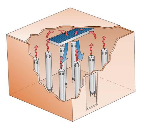
11 Systems with variable air flow VAV system In VAV systems (Variable Air Volume) the air flow supplied to each room varies as required, yet the temperature of the supply air is kept constant, i.e. the supply air temperature does not change with a change in load. On the other hand, seasonal control of the supply air temperature takes place, as a function of the outdoor temperature. COMFORT COOLING The airflow to each room is regulated by means of a damper inside some form of terminal unit in direct connection to the room, while central supply air and extract air fans are controlled by means of guide vane control or speed-controlled fan motors, usually frequency controlled. Control normally occurs by maintaining constant static pressure with sensors in the farthest branch ducts of the supply air system. The flow varies from max. in the warmest day down to approx. 20 % of max. during the coldest days of the year, when the air only has the task of meeting the demands made on air quality. Figure 18. Principle of a VAV system. Systems with water based cooling These types of system supply the individual rooms with water based cooling. The air system used only satisfies the demands on air quality. In a conversion or refurbishment situation it is preferable to use this type of cooling system. When installing the system there is usually space in the existing suspended ceiling to install the required pipes needed for the distribution of chilled water in the building. Combined systems Air based and water based cooling can be combined in many different ways. One situation when the systems must be combined is when the air based system does not have sufficient cooling capacity. Figure 19. Principle of water based cooling. It is also possible to combine air based systems so that in specific parts of a building, or in specific rooms, a VAV system is used (by utilising VAV units on which the air flow can be controlled), and in remaining parts of the building a CAV system is used. 11
12 COMFORT COOLING Conventional electrically driven compressor cooling Cooling generation using a compressor cooler is the classic method for cooling. When mechanical cooling for comfort cooling is discussed this is usually considered to be the standard. Using a compressor driven chiller gives you immense flexibility with regard to the methods of supplying cooling to the building. As previously mentioned it is possible to deliver cooling from chillers either to the cooling battery in an air treatment unit or to cooling equipment placed directly in the room, for example, chilled beams or fan coil units. Evaporative cooling Evaporative cooling of air utilises the fact that the air s temperature drops by making it moist with the help of water evaporation from a wet area that the air passes. Cooling is possible as long as the air is not saturated with water vapour. The lowest temperature the air can take with this type of cooling is limited by the air s wet temperature, which is sometimes called the air s cooling limit. Figure 20. Principle for direct evaporative cooling. Direct evaporative cooling refers to a process where the supply air is moistened and the temperature drops. At the same time the air s moisture content increases. With indirect evaporative cooling the exhaust air is moistened, whereby the exhaust air s temperature drops. This is followed by a heat exchange (without moisture transfer) between the exhaust and supply air where the heat from the supply air can be transferred to the exhaust air. The possibility to cool is mainly determined by the current condition of the outdoor air. The more moisture (the higher t wet value) it contains the poorer its ability to cool. Consequently, the method is considered to have limited use in offices and other commercial premises. Sorptive cooling In order to lower the temperature of the supply air as far as possible, it is beneficial to have the driest possible air when moistening starts. In the sorptive cooling process moistening from the evaporative process is supplemented by drying of the supply air before it is moistened, see Figure 22. Figure 21. Principle for indirect evaporative cooling. A sorption cooling unit consists of a dehumidifier section that dries the air and a section that cools the air (the evaporative part). The supply air is dehumidified using a moisture absorbing rotor. On the exhaust air side the absorbed water is driven out of the rotor. Heat is used for this. Accordingly a sorptive cooling unit also needs to supply heat. Figure 22. Principle for sorptive cooling. 12
13 District cooling It is becoming increasingly common for energy companies to offer their customers district cooling. Depending on the requirements of each individual energy company concerning the production possibilities and the layout and proximity of customers, cooling is produced and distributed in different ways in different districts. In a district cooling system production units can be made up of everything from free cooling (e.g. cold sea water that can be utilised directly for cooling purposes), compressor coolers, to heat driven cooling machines. COMFORT COOLING It is relatively common to utilise cooling from existing heat pumps that are already used to deliver heat to the district heating system. Initially it was usual that users with a relatively large cooling requirement were connected to the district cooling system. This typically could be a hospital area or a shopping centre. However, it is becoming more common that individual properties are being offered the opportunity of being connected. Chilled water is delivered to the customer in a substation, in principle the same way as a subscriber centre for district heating. From here secondary water is distributed to the building or buildings to be cooled as set out in Figure 23. In the same way as for district heating, it is important to be aware of the conditions provided by the supplier of the district cooling. It is normal for suppliers to state the following conditions: Temperatures: for example, t supply - t return = 6-16 or 7-17, i.e. Δt = 10 K. Flow charge: which increases in those cases the temperature difference decreases in relation to that agreed. Free cooling There is a possibility with water based cooling systems to use what is known as free cooling. Here it is necessary to install some form of heat exchanger to the outdoor air. This is usually integrated in the comfort cooling unit, see Figure 24. A heat exchanger is connected between the liquid cooler unit s refrigerant and cooling medium circuits. In connection with the utilisation of free cooling when using water based cooling it is common that at a predetermined outdoor temperature you allow all water to be cooled against the outdoor air. Accordingly, at lower temperatures than this temperature the cooler is not used. The outdoor temperature at which switching occurs normally lies around 10 C. It is also common to utilize free cooling by installing heat exchangers and reversing valves between the building s brine system from the liquid cooling unit and the cooling medium system, from the cooling unit s cooling medium cooler. Figure 23. Principle for district cooling Figure 24. Cooler with free cooling. 1. Condenser 2. Heat exchanger for the cooling medium 3. Outdoor air 4. Cooling medium return 5. Cooling medium supply 6. Evaporator 7. Compressor
14 COOLING ROOMS COOLING ROOMS The room can be cooled in a number of different ways. Below we describe how chilled beams, cooling panels, comfort modules, fan coil units and induction units operate in general and what characterizes each system. Provides cooling in the form of radiation The cooling effect is limited to approximately 100 W/m 2 of the active area. COOLING ROOMS Chilled beams A chilled beam primarily gives off its cooling effect through convection, i.e. circulating indoor air that flows through the cooling battery, see Figure 25. The chilled beam can also be combined with a supply air connection to simultaneously work as a supply air device and in many cases, due to the induction effect, increase the cooling effect in the beam, see the section Induction units. At Swegon, we call units of this type: active climate beams because the function can be utilized both for the cooling and heating of premises. The chilled beam s cooling is usually regulated by a control valve, which sometimes controls several chilled beams depending on the required cooling capacity and flexibility. Figure 25. Principle of the chilled beam. Chilled beams work according to the principle dry cooling (above the dew point). The cooling medium s supply temperature should always be higher than the dew point temperature for the air in the room, see the section Condensation protection. Characteristic of active climate beams Cost efficient solution with supply air and room cooling in the same unit Relatively high cooling effect Important that the supply air is dehumidified so that condensation and thus reduced capacity are avoided Can also be used for heating as an alternative to radiators Cooling panels A horizontal under tempered area that is suspended from the ceiling is called a cooling panel, see Figure 26. Cold water passes through a pipe connected to an aluminium sheet in the cooling panel. Heat is transported from the sheet to the cold water. Cooling panels then cool the warm room air as well as absorb heat from the room through low temperature radiation. These can be surface mounted against the ceiling, individually suspended or integrated in the suspended ceiling. They essentially work as a radiant cooler. The cooling power of the cooling panels is usually on/off-controlled by a control valve that, among others, controls several cooling panels depending on the cooling capacity and degree of flexibility desired. Figure 26. Principle of the cooling panel. Cooling panels work according to the principle dry cooling (above the dew point). The cooling medium s supply temperature should always be higher than the dew point temperature for the air in the room, see the section Condensation protection below. Typical properties of cooling panels Discreet solution 14
15 Fan coil units A unit via which both heating and cooling are delivered to the room (however, not simultaneously). An outline diagram is shown in Figure 27. A fan coil unit is equipped with a fan that circulates room air through the unit. The air is heated or cooling inside the unit in a combined heating and cooling coil with two separate liquid circuits. Hot or chilled water is supplied to the coil from a central unit in the building. Of all the room cooling units, fan coil units have the greatest cooling capacity, but they also generate the highest noise level. Immense flexibility throughout its useful life COOLING ROOMS Typical properties of fan coil units Large cooling effect Can handle latent cooling if a drainage system is fitted Relatively high noise levels (at high output) High operating and maintenance costs (for changing the filter and fan, cleaning the drainage system, for instance) Induction units A unit via which both heating and cooling is delivered to the room (however, not simultaneously). An outline diagram of an induction unit is shown in Figure 28. When an induction unit is used, the ventilation air is supplied to the room via the induction unit. The ventilation air flows with high velocity through a nozzle which causes room air to be entrained by the supply air through a combined heating and cooling coil with two separate water circuits. In this way it is possible to heat or cool the room using one and the same unit without having to use a fan. Typical properties of induction units Relatively high cooling outputs Contains a function for supply air Important that the supply air is dehumidified so that condensation and thus reduced capacities are avoided Low operating and maintenance costs Comfort modules The comfort module is a completely new type of product that that can be described as a hybrid between a climate beam, a supply air diffuser and a radiator. A comfort module combines the high cooling power of a climate beam when primary air is discharged at low velocity with the supply air diffuser s capacity for quickly mixing the chilled air with room air. This creates opportunities for generating great cooling power with a considerably smaller unit than with a climate beam. The same function creates better conditions for heating the premises from the ceiling. A diagrammatic illustration of a comfort module is shown in Figure 29. Characteristic of comfort modules Small overall dimensions enable more free space for other installations in the ceiling Four-way air distribution enables a larger mixing zone and a high standard of comfort Tempers and ventilates rooms for a high standard of comfort whatever time of year (ventilation, cooling and heating) No moving parts, this means low maintenance costs 15
16 COOLING ROOMS Figure 27. Principle of the fan coil units. Figure 28. Principle of the induction units. Figure 29. Principle of a comfort module. 16
17 DESIGN DESIGN Selection key Selection data: Cooling requirement (use Swegon climate calculation software, ProClim) Heating requirement (use Swegon climate calculation software, ProClim) Air flow required (use Swegon diffuser calculation software, ProAir) Other factors affecting the system selection: Maximum permitted air velocity in the occupied zone (use Swegon diffuser calculation software, ProAir) Acoustic requirements (use Swegon sound calculation software, ProAc) Requirements for directional operative temperature (use Swegon climate calculation software, ProClim) COOLING EFFECT COOLING EFFECT AIR COOLING EFFECT WATER Product ProClim ProAir SELECTION OF DIMENSIONS THAT SATISFY THE CRITERIA DESIGN Calculation procedure 1) Calculate the supply air s cooling effect [W] P l = q l 1.2 Δt l where q l is the supply air flow [l/s] Δt l is the temperature difference between the room temperature and the supply air [K] Guide tables for the primary air s cooling capacity are also documented with the product s cooling capacities, see relevant sections. 2) The water s required cooling effect is obtained by subtracting the cooling effect of the supply air from the total cooling requirement. If the product required only provides water cooling (i.e.: passive beam), go to point 3a. If the product includes supply air (i.e.: active beam), go to point 3b. SUPPLY AIR IN THE PRODUCT NO YES HEATING FUNCTION NO YES SATISFY ACOUSTIC AND DRAUGHT CRITERIA IS THE HEATING EFFECT SATISFIED? NO YES NO YES 3a) Use the tables that show the water cooling effect per chilled beam as a function of the mean temperature difference and select a suitable chilled beam with a capacity corresponding to the calculation in point 2 or the number of chilled beams if one is not sufficient. CALCULATE RESULTING FLOWS AND PRESSURE DROPS 3b) Use the tables that show the cooling effect per chilled beam as a function of the mean temperature difference. Select the nozzle configuration that matches the preferred air volume. Select a ceiling unit with the preferred air flow or interpolate between close air flows. Check that the sound level is acceptable. Figure 30. Selection key. 4) The water flow at the chosen Δt on the cooling water is obtained from the diagrams Water flow - cooling effect. 5) The pressure drop on the cooling water circuit in the product is then calculated with the help of the formula Δp k = (q k / k pk ) 2 where k pk is documented in the table as the cooling capacity. 6) Heating. Use the corresponding method as set out in points 3-5 above. 17
18 DESIGN System design Cooling system The cooling system should be constructed as an indoor evaporator. The surplus heat is led away either through outdoor condensers, or via a brine system and cooling fluid grids placed outdoors. In order to ensure the drying of the air at high outdoor temperatures and high relative humidity the supply air temperature should be weather compensated as set out in Figure 32. The engagement point of +5 C can vary a little from installation to installation. See the dashed alternative curve. However, it is important, at outdoor temperatures around + 22 C and above, to achieve dehumidification after the air handling unit so that the supply air s dew point temperature is lower or equal to the supply temperature of the cool ceiling s cooling medium. 2 3 If instead an outdoor cooling appliance is chosen, i.e. the evaporator is placed outside, the placing of indoor auxiliary exchangers is recommended This is in order to avoid an antifreeze fluid (brine) in the cooling water circuit. There are two reasons why brine should be avoided in the cooling water circuit. The pressure drop is increased by 15-25% depending on the strength of the brine solution. The cooling effect is also reduced by approx. 15% due to the fact, that the heat transmission factor becomes lower on the water side. 1 4 The most common system is one with water tube boiler evaporators in which the cooler s cooling fluid takes up energy from the cooling water circulating in the building. For environmental reasons, this solution must be preferred despite the loss of effect in the exchanger. Regulation of room units Chilled beams and perimeter systems are almost exclusively connected through two-way valves. The advantages compared to a three-way union are lower costs and simpler design and adjustment. Overpressure valves are positioned in a few areas of the system to prevent high pressure at low loads. The fact that pressure regulated pumps can now be installed to a reasonable cost, contributes towards the preference for a two-way system. Condensation protection On hot days in late summer, the air humidity can be high. The higher the humidity in the air, the higher the dew point temperature for condensation on surfaces. A Mollier diagram (moisture-enthalpy-diagram) will show the relationship, see Figure 34. At, for example, 25 C and 50% relative humidity the dew point is 14 C (applicable to normal atmospheric pressure, 101 kpa), i.e. it starts to condense on surfaces whose temperature is 14 C or lower. On some late summer days after a rain shower the dew point temperature can sometimes rise to 15 C and in extreme cases up to 17 C. In order to avoid condensation problems, measures should be taken to ensure that the system prevents condensation on the room units. The supply air should always be chilled in order to prevent condensation in the cooling battery on the supply air unit. Figure 31. System solution. 1 = Water tank 2 = Water cooler 3 = Air treatment unit 4 = Controller 5 = Differential pressure valve 6 = Chilled beams Figure 32. Supply air compensation in relation to outdoor air temperature. 6 5 Another method is to use a sensor that measures the relative humidity of the exhaust air, see Figure 33. The shunt group valve is controlled to hold the water temperature above the dew point temperature. 18
19 1 3 DESIGN 2 RC GX GT 5 4 Figure 33. Condensation protection control via the shunt group. 1 = Evaporator/condenser 2 = Circ. pump 3 = Shunt 4 = Exhaust air duct 5 = Chilled beam RC = Controller GX = humidity sensor GT = Temperature sensor 19
20 DESIGN Design of condensation protection Proposals are given here for suitable pipe system designs with associated control and adjustment valves to provide interaction between the air treatment s drying of the supply air through condensation and the chilled water temperature to the chilled room unit to counteract condensation. to the calculated value. The resulting flows and temperatures are evident from Figure 35. The system has been selected for the state DUT = +25 C and RH = 50% which corresponds to a dew point of +14 C. The cooling medium side s selected temperature to the cool ceiling is set to +13 C on the supply and +17 C on the return, see Figure 34. On the air treatment side the cooling battery is selected for +8 C on the supply temperature and +13 C on the return temperature. These are the temperatures that provide good conditions even with district cooling. Here an installation of 1000 m 2 with a supply air flow of 1.5 l/s m 2 has been assumed. With district cooling a return temperature preferably higher than +16 C is wanted, which is achieved for installations with combined air and chilled unit conditioning. It is then important to also maintain the return temperature from air treatment so that it does not lower the return temperature to the district system s heat exchanger. As is evident from the Mollier diagram s curve for the above selection data an enthalpy difference Δi of 16 kj/kg is obtained. P TL = q TL p TL Δi [kw] P TL = = 28.8kW P TL = requisite effect for cooling the supply air with associated condensation precipitation at DUT ρ TL = density of the supply air in kg/m 3 q TL = the supply air s flow in m 3 /s The above gives a selected chilled water flow q w at ΔT W = 5 K (+8 C to +13 C), and P TL = 28.8 kw q w = P TL / (ΔT W c p ) = 1.72 l/s q w = 28.8 / ( ) = 1.72 l/s ρ w = the density of the water kg/m 3 c p = the water s specific heat in kj/kg C = ρ w c p / 1000 In the equivalent way, for the chilled room unit section 1000 m 2 40 W/m 2 = 40 kw is obtained in the required cooling effect. q wk = 40 / ( ) = 1.38 l/s. Try the bypass flow 0.09 l/s to the three-way valve SV1 past the air cooler. With the help of the separate flows and their temperatures the mixing temperatures in the pipe system s separate parts are then calculated. From the calculated mixing temperatures it is evident that they interact well in the design instance. The adjustment valves should be measured with the control valve s port fully open against respective adjustment valves when the established flow for the RV valve is adjusted Figure 34. Condensation protection operating instance 1. Change of state for the supply air. 1,72 l/s, 8,0 C 0,09 l/s, 8,0 C RV RV 1,82 l/s, 8,0 C SV RV 1000m 2 x 1,5 l/s m 2 = 1,5 m 3 /s 1,72 l/s, 13,0 C SV 1,82 l/s, 12,75 C 2,38 l/s, 13,0 C 0,09 l/s, 17,0 C 1,82 l/s, 17,0 C 2,38 l/s, 17,0 C 1000m 2 x 40 W/s m 2 = 40 kw Figure 35. Condensation protection operating instance 1. System principle with flows and temperatures. 20
21 Temperatures The temperatures given below serve merely as a guide. Differences are likely to occur. DESIGN Recommended temperatures Supply temperature, cooling: >13 C (see section Condensation protection) Temperature increase cooling: 2-4K Ventilation air when cooling: see Figure 32 Room adjustment Regulation of the room temperature normally takes place individually in each room via a room temperature controller. The room unit controls cooling and (where relevant) the heating valve in sequence so that the room does not receive heating and cooling simultaneously if the building is new. In older buildings with inferior insulation, it should not be assumed that cooling and heating should always occur in sequence. Here it is recommended that the directed operative temperature is be checked. It may be the case that you need to have heating by the perimeter wall at the same time, as there is a cooling requirement in the internal zones. 21

22 SWEGON WATER BASED CLIMATE SYSTEMS DESIGNING WITH SWEGON CLIMATE BEAMS The principle of Swegon climate beams is that the primary air creates an even mixing effect in the space for the fresh air and additionally, via induction, to circulate the room air through the integrated batteries and thus cool the room air. Different air patterns can be created allowing adaption to different archetectual designs and layouts of the building, the placement of the heat loads and ceiling units. Corridor facade (perpendicular to facade) This installation alternative is well suited for use in cellular offices. The product can be located in any position either centred in the middle of the room or somewhere along one of the wall partitions. Central placement is the conventional alternative that is appropriate for all beams, both with or without supply air and/ heating. Products with or without supply air can be located somewhere along a partition wall. In supply air applications, it may be appropriate to utilize asymmetrical air discharge. From the climate beam position, the air can follow the ceiling, wall and part of the floor and mix with room air along this stretch and increase the temperature in the circulated air to in this manner provide a comfortable indoor climate in the premises without risk of draught. Thanks to the long mixing zone, the air volume and impulse can vary within a large range without the risk of draught in the occupied zone becoming too high. This is why the disc configuration need not necessarily be changed if the rate of airflow is changed. SWEGON WATER BASED CLIMATE Advantages: Easy connection of water and air to the corridor. Back (parallel to facade) The rear edge solution is well suited for use in cellular offices and open-plan offices. Symmetrical or asymmetrical air discharge can be selected depending on the volumes of supply air to be discharged. Keeping in mind that the greatest percentage of the heat loads are normally present in the nearest perimeter wall, the air discharged downward acts together with the heat load and this results in excessive air velocity along the floor. At least 50% of the supply air should therefore be aimed toward the perimeter wall and be controlled by means of Anti-Draught Control. Products that radiate heat should normally not be installed at the rear edge of the room. To obtain a small degree of radiant asymmetry, it is advisable to install radiators or radiant heating along the perimeter wall. Advantages: Easy connection of water and air to the corridor. Front (parallel to facade) The front edge solution is well suited for use in cellular offices and especially in open-plan offices. This location is extremely well suited for products with cooling, supply air and heating function. If the nozzle or disc pressure is high and air is discharged to the zone near the perimeter wall, it is appropriate to use asymmetrical air discharge. If the unit is located nearer to the centre of the room, uniform air discharge works best. Advantages: All the climate functions in a unit are simple to design into the project and install. In an open-plan office, this solution usually enables the fitter to install the products with greater distance from one another than if they are installed aligned in a corridor-to-perimeter wall direction, which may increase opportunity for higher cooling capacities. Allowing space between the short sides of the units offer considerable flexibility when it is time to erect or move partition walls without interfering with the standard of comfort in the room. Cellular office In a cellular office, there is always a long mixing zone before the air below room temperature that leaves the ceiling unit reaches the persons in the occupied zone. Figure 36. Corridor perimeter wall-oriented climate beams in cellular offices. Figure 37. Climate beams installed at the rear edge in cellular offices. 22

23 SWEGON WATER BASED CLIMATE Figure 38. Climate beams installed at the front edge in cellular offices. 23

24 SWEGON WATER BASED CLIMATE SYSTEMS Large open-plan rooms Typical open-plan rooms are shops or open-plan offices. The conditions for climate beams in an open-plan room are different than in an individual office room. In this case, there usually are not any wall surfaces along which the lower-than-roomtemperature air currents can flow, other than the perimeter walls, see Figure 39. This is why Anti-Draught Control is always advisable and then particularly in corridor perimeter wall oriented installations with units that discharge air towards one another. The front-edge placement can also be recommended, see the section above. With a mixing system there can be a vertical movement between the room air and the cooled supply air. The system must be designed in such a way from the outset to eliminate the risk of draught due to requirements of flexibility relating to furnishings, partition wall placement, etc that are generally required for modern open plan offices. The Swegon calculation software for climate beams, ProSelect, includes all essential data necessary to carry out the design. Advantages: Products with supply air offer excellent air discharge and mixing performance without disturbing noise and without draught. To consider: Passive beams should be arranged in the direction of the convection currents, otherwise there is a risk of reduced capacity. In the same way, diffusers should be placed so that they distribute air along the chilled beams. Always specify ADC for the active units. Figure 39. Locations of climate beams in large open-plan rooms. 24


25 DESIGNING WITH SWEGON COMFORT MODULES A comfort module is a hybrid between a traditional chilled beam, disc air diffuser and a radiator, and combines the following qualities: The chilled beam s high cooling and heating capacity when air is supplied at low velocity The disc air diffuser s capacity for quickly mixing supply air with room air The radiator s heating capacity This unique combination offers completely new capabilities. The distribution of supply air in four directions (see Figure 40) creates a large mixing zone. This makes it possible to provide high cooling capacities with a product that requires less space in the ceiling. SWEGON WATER BASED CLIMATE Cellular offices A comfort module can be located anywhere in a cellular office without causing draught. By adjusting the air discharge directions of the comfort module based on where the unit is installed, the fitter can optimize the comfort in the room from case to case. A good example of this is a comfort module suspended from the ceiling near the rear-edge of the room (see Figure 41). 4-way air discharge makes it possible to utilize the corridor wall, ceiling and partition walls for mixing supply air with room air. In contrast to traditional two-way air discharge, this provides lower air velocities, especially at floor level. Figure way air distribution with the ADC in the Fanshape setting. Benefits: The same product provides optimal comfort regardless its location in the room. Open-plan rooms The comfort modules 4-way air discharge really shows to advantage in open-plan rooms. Utilizing the built-in ADC (Anti- Draught Control) in the Fan shape setting (Figure 40), creates a totally all-round spread pattern. In contrast to the chilled beams tendency to locally cause slightly higher air velocities in open-plan rooms, comfort modules distribute air more uniformly throughout the premises. This means less risk of possible draught and better comfort. Since the useful life of the product normally is longer than the intervals between rebuilding or refurbishing buildings, high demands are made on flexible systems. Thanks to the built-in nozzle control function and ADC, there is good chance that you can keep the existing installation even though the indoor comfort considerations change. Figure 41. Comfort module located at the rear edge in an office room. Benefits: Highly uniform air distribution and air velocity in the premises. Enormous flexibility in response to airflow rate changes and possible altered room conditions. 25
26 SWEGON WATER BASED CLIMATE SYSTEMS Heating function New building nowadays involves the construction of perimeter walls with extremely low U value. At the same time, the quality of the windows installed has improved immensely in recent years. This means higher surface temperature on the inside of the window resulting in less radiant cooling energy emission and a minimum of cold downdraught. A much better perimeter wall also reduces the heating requirement in the winter and this means that heat seldom needs to be conveyed to the premises while the room is in use. Internal heating sources are most often sufficient for heating the room during the day. When less radiant cooling energy is emitted from windows, this reduces the need for traditional radiators for increasing the operative temperature. Since the comfort modules mix supply air faster than a chilled beam, the temperature difference also decreases faster. This in combination with improved structural engineering makes it possible to heat rooms with comfort modules in a better way than with traditional chilled beams. In fact, it is even possible to heat rooms with comfort modules even in many housing improvement projects. The operative temperature and other variables can be calculated very effectively by means of Swegon ProClim software. ProClim is available at Swegon home page. Detailed full-scale reports that give you an idea of what it may look like in an office room heated by a comfort module are available for you to study. Figure 42 shows an excerpt from an article dealing with simulated winter conditions. Figure 42. Illustration from full-scale tests involving heating with a comfort module. 26
27 DESIGNING WITH SWEGON PERIMETER WALL UNITS Installation along the perimeter wall Just as the name implies, the system is mainly intended for location along a perimeter wall. Swegon PRIMO perimeter wall system always includes cooling, heating and ventilation functions. The system provides excellent comfort both while cooling and heating. Benefits: Complete indoor climate system including control equipment. Well suited for rooms with low ceilings. Little maintenance and low service costs. Offers flexible room solutions that make it possible to move partition walls without upsetting the degree of comfort in the room. The max. permissible flow temperature indicates the highest temperature recommended for continuous operation. Note that substantial and rapid temperature fluctuations, especially in radiant ceilings but also to a certain degree in climate beams with flanged coils, may give rise to clicking sounds due to linear expansion in components and fitting. High flow temperatures (60-80 C) are only permissible if the need for heating is great and must always follow the outdoor temperature so that the flow temperature will drop as the need for heating diminishes. This is also preferable from an energy-saving point of view since the losses in the pipe system will then be lower. High temperature systems should be avoided if their room temperature control method involves products continuously being heated up and cooled down. SWEGON WATER BASED CLIMATE Recessed in floors Can also be installed horizontally recessed in a raised floor if one exists. Benefits: Complete indoor climate system including control equipment. Enables solutions with windows that extend down to the floor (so-called glazed facades) yet the installation will not have any effect on the room s general appearance. Installation in ceilings Another alternative involves installing a unit in the front or rear edge of the room. A typical example of this is an installation in a hotel room. In this example, the normal hall section with a suspended ceiling transforms into a room without suspended ceiling. A perimeter wall unit can be installed horizontally in the space above the suspended ceiling in the hall. This unit will provide the room with ventilation, cooling and heating. Benefits: Complete indoor climate system including control equipment. Recommended limit values Recommended limit values for the product are specified at the bottom of the last page of every product section. On the water side, limits are specified for operating pressure and pressure for pressure testing a completed installation. The specified pressures refer to the operating and test pressures of the coils. In most cases, the pipe fittings and valves are the components that limit the total pressure of the system. The min. permissible water flow is specified for the cooling and heating coil circuits. This refers to the minimal flow required for ensuring that any air remaining in the circuit will be entrained by the liquid. The lowest flow temperature is determined by the dew point temperature and must always be sized so that the system will operate without condensation forming on coil and pipework surfaces. See also the section entitled Condensation protection. 27


28 SWEGON WATER BASED CLIMATE SYSTEMS Figure 43. Perimeter wall units installed below windows in a cellular office. Figure 44. Ceiling-mounted perimeter wall unit in a hotel room. 28
29 Full-scale test in a laboratory Swegon has well-equipped ventilation engineering laboratories at its production facilities in Tomelilla, Arvika and Kvänum. Extensive research development work is carried out in the development and production of new products to clarify and substantiate the function and performance of the products. An important part of this work involves full-scale tests to simulate indoor climate conditions. The purpose of these tests is to find out what the practical limits are for using the products and what recommendations are required for advising and guiding clients through the planning phase of a building project. Simulating a room and room conditions in a laboratory environment requires a layout and furnishings that resemble those of the relevant room as much as possible. To achieve correct levels of heating and cooling needed, an indoor climate calculation should always be the basis for sizing an indoor climate system. An ideal method is to make use of Swegon ProClim calculation program (see ) or seek the help of your nearest Swegon sales representative. When you have determined the design considerations of the premises, get in touch with our sales representative and plan a test to be carried out at any of the company s laboratories. You will then have the opportunity to observe the test and study what results are attainable. distance between units discharging air toward one another. The specified distances between units and to walls are reference parameters based on extensive laboratory measurements and many years of experience. By means of the ADC (Anti-Draught Control) function, both the spread pattern and the depth of penetration can individually be changed on every ceiling unit. This capability makes them highly flexible. The number of setting combinations is vast and the most common spread patterns are specified in each product datasheet. The Swegon ProSelect sizing program is well-suited for use in calculating the recommended minimal permissible distance between units and to walls. Rotatable supply air discs Swegon climate beams must be able to offer an optimal supply of primary air and circulated air below room temperature with low air movement in the occupied zone, regardless of the volume of the primary airflow. Certain products can therefore be equipped with built-in supply air discs. The distribution of air is then variable in that the discs are rotatable. This type of supply air disc is of the same design as those of Swegon disc diffusers. The supply air discs are well-suited for use in rooms where more air is needed than a normal climate beam can handle, for example in a conference room. SWEGON WATER BASED CLIMATE As an alternative to full-scale testing, Swegon can also offer advanced computer simulations (CFD). This may be especially of interest in cases when it is not practical to physically build up the topical premises. Typical examples of this are sport halls, concert halls and other large rooms. CFD simulation gives a good idea of the sequence of events in a room and can easily be visualized in various colour ranges. Nozzle configuration The capacity data for ceiling units is usually presented for various nozzle configurations. The configurations provide individual product-unique coefficients of performance that enable the designer to optimize the airflows, nozzle pressures and flow direction for each type of room and product placement. Two-way symmetrical air discharge is used in climate beams in most applications (50-50%) but they can also be configured for asymmetrical two-way discharge with greater airflow to the right or left (75-25%), for instance. The selected configurations can be changed at a later phase by removing plugs from the plugged nozzles. Comfort modules are also equipped with nozzles yet with a simplified use. By making a simple modification, the units nozzle setting can be individually changed for discharging more or less airflow on all four sides. This gives the user every opportunity to adapt the airflow and the direction of airflow to current needs throughout the useful life of the product. ADC air deflectors The spread patterns of the various ceiling units are presented in the ProSelect calculation program. The purpose is to be able to provide source data to enable the designer to determine the distance to the wall or some other obstacle, as well as the Figure 45. Example of ADC with various settings. 29
30 SWEGON WATER BASED CLIMATE SYSTEMS BSA flush-mounted in suspended ceilings It is important to arrange circulated air openings in the suspended ceiling so that the BSA will obtain the correct circulated airflow. Circulated air openings having a net area of at least 0.1 m 2 in the suspended ceiling are required for each linear metre of climate beam. L L If possible, the circulated air openings must be arranged along the short sides of the unit. Where this is not possible, locate the circulated air openings at a distance (L) of at least half the recommended distance between the two units. See Figure 46. Distance between climate beams Detailed recommendations about the correct distance between units can be obtained using the ProSelect sizing program available at. Figure 46. Recommended locations of circulated air openings in the suspended ceiling for the BSA. Maintenance Swegon ceiling units, chilled beams, comfort modules and perimeter wall units are characterized, among other attributes, by the fact that they do not contain any moving parts. Therefore, they do not require maintenance other than cleaning. The interval for cleaning varies depending on the type of product, where the product is installed and the nature of the activities conducted in the room. However, under normal operating conditions, chilled beams, ceiling units and comfort modules should be cleaned every 5 years and perimeter wall units every 2 years. In rooms where higher dust concentrations can be expected in the air, the units should be cleaned more often. This is typical in hotel rooms. Clean painted surfaces with a mild soap solution. Never use a cleaning solvent as doing so may damage the painted surface. Air ducts (wherever applicable) are cleanable from an opening in the duct after removing the cleaning cover. Vacuum clean coils by moving the nozzle over the external surfaces of the coils. To clean some products, you can vacuum out the dust through the perforated bottom section without having to remove the face plate. In general, coils mounted above a suspended ceiling seldom require cleaning because the circulated air gives rise to extremely low air velocities. Inspect the condition of suspension parts and visible soldered points while cleaning. If any part is loose or if you find water droplets on soldered points, you must closely examine the unit and remedy any defects. 30
31 GUIDELINES GUIDELINES Test methods for water-based indoor climate systems Test standards are needed to be able to compare products from different suppliers. It is only then that product data will be of equal value, comparable and unambiguous. The standards that have been applicable in Europe have been the Nordtest method NT VVS 078 "Ceiling Cooling Systems" and the so-called V Method in Swedish Association of Air Handling Industries V Publication 1996:1 (mainly in Sweden). At the same time in Germany, a DIN Standard has been drawn up for flat chilled ceilings, which is also used for passive chilled beams (chilled beams without supply air). Nordtest and V Publication The Nordtest and V methods are relatively similar. The V Method is a slightly revised version of the Nordtest method and was produced by the Swedish Testing and Research Institute and the then Swedish Association of Air Handling Industries (now: Svensk Ventilation, also called SwedVent) together with some suppliers from Sweden and Finland. The main difference between the two methods is at which water flow the products should be tested. In the Nordtest method, the water flow is fixed and related to the pipe diameter in the heat exchanger, i.e. all products are tested with the same water flow irrespective of the cooling capacity. The purpose of the V Method was to allow products to be tested using an operating scenario that reflected true conditions and it was then chosen to steer towards the water flow that provides a temperature difference of two degrees through the heat exchanger. This means that if two products have a different cooling capacity, then they should be tested at different water flows. The test room consists of two rooms, as in Figure 47, where heat is indirectly supplied to the inner test chamber via the floor and walls. The heating balances the supplied cooling capacity during the measurement sequence on the test object so that the test chamber s temperature is constant. DIN 4715 In the German DIN 4715, the test room is somewhat different, Figure 48. Here, the test chamber consists of an insulated room. Inside the test chamber, the test object s cooling capacity is balanced by means of "dummies" (occupant simulators) that emit heat directly in the room. EN Standards As chilled beams are now starting to be used in other parts of Europe, work was started in 1996 to produce common European Test Standards. Since the start, Swegon has been an active party in this joint European effort that is now in the process of being finalised with three new Standards. Today, there is a new standard for flat chilled ceilings, EN 14240, one for passive chilled beams, EN as well as one draft (preliminary standard) for active chilled beams, pren Both types of test rooms (Figure 47-48) can also be used from now on for testing chilled beams according to the new EN Standards. At EuroVent, work is also in progress for the certification of chilled beams and this will probably be implemented sometime in The suppliers that participate in this work, among them: Swegon, will then refer to the new EN Standards for determining capacity data for cooling applications. To consider Regardless of whatever standard referred to, there is an underlying test method for producing product performance data. The new EN Standards are very similar to the old and the difference is first and foremost how the reference temperature in the test room is measured. Previously, it was calculated at a level of 1.1 metres above the floor whereas the new standards for chilled beams always refer to the on coil temperature, i.e. a temperature near the chilled beam. Previously it has been discussed whether chilled beams constitute a fully mixing air distribution system or if it is warmer up by the ceiling. When we use on coil temperature as a reference, this discussion becomes uninteresting. The product details for active chilled beams will probably remain unchanged. Passive chilled beams, based on natural convection, may on the other hand be affected since the testing is carried out without supply air and this causes a stratification in the test room. This stratification has previously not been taken into account. Note that the test methods in question do not necessarily correspond with the operating scenarios that may come into question when designing an indoor climate system. In the standards, the cooling water system is designed for a two degrees temperature difference in the inlet and outlet pipework, while most such systems are designed for a three to four degree difference. To determine the correct cooling performance, the cooling capacity must therefore be recalculated for the appropriate cooling water flow. In Swegon documentation, all capacity data is based on a fixed water flow to make it possible to easily correct the preferred water flow. These correction curves are always available in connection to each product data specification. For reasons of simplicity, the Swegon ProSelect, BeamSelect and ProPipe calculation software is recommended for products with water cooling. This automatically corrects the cooling capacities to the relevant preferred water flow. GUIDELINES 31
32 GUIDELINES Figure 47. V-method. Figure 48. DIN
C o o l i n g a n d h e a t i n g s y s t e m s
 2 C o o l i n g a n d h e a t i n g s y s t e m s Cooling ceiling system description Preliminary remarks Cooling ceilings Cooling ceilings are room cooling systems for placement in the ceiling zone. Their
ASHRAE JOURNAL ON REHEAT
 Page: 1 of 7 ASHRAE JOURNAL ON REHEAT Dan Int-Hout Chief Engineer Page: 2 of 7 Overhead Heating: A lost art. March 2007 ASHRAE Journal Article Dan Int-Hout Chief Engineer, Krueger VAV terminals provide
BTBa. FLUSHLINE Ventilated chilled beam for cooling, heating and ventilation. BTBa
 FLUSHLINE Ventilated chilled beam for cooling, heating and ventilation BTBa CEILING UNIT FLUSHLINE BTBa FLUSHLINE BTBa is a complete climate system offering immense flexibility. Ideal for large areas with
Comfort and health-indoor air quality
 Comfort and health-indoor air quality 1 The human body has a complicated regulating system to maintain the human body temperature constant most of the time, which is 98.6 F (36.9 C) regardless of the environmental
Modular Active. Chilled. Beams
 Modular Active Chilled Beams How Twa MAC Beams Work Primary air (100% outside air) is dehumidified to between 50-57 F dew point and is used to: control the latent requirements of the space, provide fresh
Experimental study of space cooling using ceiling panels equipped with capillary mats
 Experimental study of space cooling using ceiling panels equipped with capillary mats Tiberiu Catalina and Joseph Virgone University of Lyon, France Corresponding email: tiberiu.catalina@insa-lyon.fr SUMMARY
Air Conditioning Clinic
 Air Conditioning Clinic Psychrometry One of the Fundamental Series D C B A C B D A July 2012 TRG-TRC001-EN Psychrometry One of the Fundamental Series A publication of Trane Preface Psychrometry A Trane
Primo Hotel. General. Indoor climate units for hotel rooms
 Indoor climate units for hotel rooms General Primo Hotel indoor climate unit Ceiling-mounted indoor climate units for ventilation, cooling and heating High capacity; occupies little space Dry system without
Unit 4: Science and Materials in Construction and the Built Environment. Thermal Comfort
 2.1 Introduction Thermal Comfort The thermal comfort of human beings is governed by many physiological mechanisms of the body and these vary from person to person. In any particular thermal environment
CHAPTER 4. HVAC DELIVERY SYSTEMS
 CHAPTER 4. HVAC DELIVERY SYSTEMS 4.1 Introduction 4.2 Centralized System versus Individual System 4.3 Heat Transfer Fluids 4.4 CAV versus VAV Systems 4.5 Common Systems for Heating and Cooling 4.6 Economizer
Halton Vario Design Guide
 Halton Vario Design Guide Enabling Wellbeing Table of contents 1. Halton Vario - ventilation and air conditioning system overview 3 1.1 Room level, Zonal level and central level 4 1.2 Flexible design and
Chilled beams. TRACE 700 incorporates two chilled beam strategies: passive and active.
 TRACE 700 incorporates two chilled beam strategies: passive and active. Passive chilled beams consist of a fin-and-tube cooling coil, contained in a housing (or casing), suspended from the ceiling. Chilled
Chilled beam technology overview John Woollett 1, Jonas Åkesson 2 Swegon AB 1,2
 Chilled beam technology overview John Woollett 1, Jonas Åkesson 2 Swegon AB 1,2 john.woollett@swegon.se, jonas.akesson@swegon.se SUMMARY The main focus of the paper will be on active beam technology regarding
product application data PERFECT HUMIDITY DEHUMIDIFICATION SYSTEM
 product application data PERFECT HUMIDITY DEHUMIDIFICATION SYSTEM 551B 581B DuraPac Plus Series Sizes 036-150 3to12 1 / 2 Tons Cancels: New PAD 551B.36.2 10/1/04 CONTENTS Page INTRODUCTION.................................
Everything you need to know about Radiant Heating but didn t dare ask
 Decorative radiators Comfortable indoor ventilation Heating and cooling ceiling systems Clean air solutions Everything you need to know about Radiant Heating but didn t dare ask Introduction Radiant heating
Ventilation Strategies for Healthy IEQ and Energy Efficiency
 Ventilation Strategies for Healthy IEQ and Energy Efficiency Lars Ekberg Energy Management AB A Chalmers Industriteknik Company The purpose of ventilation + - Pollution Climate Heat Pollution 2 Examples
FAST AND ROBUST BUILDING SIMULATION SOFTWARE. Chilled Beam Performance: 1 Shelly Street, Sydney
 FAST AND ROBUST BUILDING SIMULATION SOFTWARE Chilled Beam Performance: 1 Shelly Street, Sydney 3D Model Creation 1 Shelley Street, Sydney 3D Model Creation 1 Shelley Street, Sydney Daylight Analysis 1
Technical description. Atec.
 www.thermia.com Thermia Värmepumpar is not liable or bound by warranty if these instructions are not adhered to during installation or service. The English language is used for the original instructions.
To describe human body heat transfer, the concept. Thermal comfort with radiant and convective cooling systems. Articles. REHVA Journal June
 Thermal comfort with radiant and convective cooling systems Risto Kosonen Halton Oy and Aalto University risto.kosonen@halton.com Panu Mustakallio Halton Oy The difference in thermal conditions between
Cooling and heating systems. Static cooling ceiling system SKS-5/3 for visible installation
 Cooling and heating systems Static cooling ceiling system SKS-/3 DS 10 E 01.010 Static cooling ceiling system SKS-/3 Main features Preliminary remarks / Applications 3 Main dimensions and materials 3 Construction
Secondary systems used in Europe.
 Secondary systems used in Europe. Production Distribution Consumption Preface Secondary systems are the parts of the heating systems with a lower pressure and temperature level, installed in buildings.
7. MECHANICAL SYSTEM DESIGN
 7. MECHANICAL SYSTEM DESIGN The second primary topic of this thesis is to investigate the application of a dedicated outdoor air system (DOAS) to the SLCC. The stated goals for this thesis of improved
UFAD and Displacement Ventilation. Dan Int-Hout, FASHRAE Chief Engineer Krueger Richardson, Texas
 UFAD and Displacement Ventilation Dan Int-Hout, FASHRAE Chief Engineer Krueger Richardson, Texas UFAD and DV Systems, Objectives: Understand Differences between: Well Mixed, Partially Stratified and Fully
Impact of heat load distribution and strength on airflow pattern in rooms with exposed chilled beams
 Impact of heat load distribution and strength on airflow pattern in rooms with exposed chilled beams Risto Kosonen 1, Arsen Melikov 2, Boryana Yordanova 2 and Lyuben Bozkhov 2 1 Halton Oy 2 International
KLIMA Active Chilled Beams
 KLIMA 2 600 Active Chilled Beams Index Subject Page Index 1 Introduction 2 General description 3-4 Product features 5-6 Dimensions 7 Performance data 8-11 Section example Guide specifications 13 1 Introduction
Chilled ceiling guide, passive beams
 l i nda b c hi l l ed c ei l i ng gu id e Contact, Overview, Index Guideline heating and cooling Plexus Professor / Professor Plus Premum / Premax / Solus Solo Architect Polaris I & S Plafond Podium Celo
MECHANICAL SERVICES 101. Ian White
 MECHANICAL SERVICES 101 Ian White Contents 1. Ventilation 2. Heat Gains & Losses 3. Heating Ventilation Air Conditioning (HVAC) Systems What are Building Services Building Services incorporate all aspects
GEOTHERMAL DESIGN GUIDE
 GEOTHERMAL DESIGN GUIDE BENEFITS OF THE BULLDOG SYSTEM CGC Version CGC Group of Companies Incorporated 2018 CONTENTS INTRODUCTION... 2 CHALLENGES FACING CONVENTIONAL GSHP SYSTEMS... 3 FACTORS WHICH IMPACTS
BALANCING ENERGY EFFICIENCY & INDOOR THERMAL COMFORT
 BALANCING ENERGY EFFICIENCY & INDOOR THERMAL COMFORT Ashak Nathwani AM Adjunct Senior Lecturer ashak.nathwani@sydney.edu.au PRESENTATION THREE SESSIONS This presentation will be in three parts addressing
Optimizing the use of Chilled Beams for health and comfort GUNNAR SVENSSON
 Optimizing the use of Chilled Beams for health and comfort GUNNAR SVENSSON Lighting Sound Level Air Quality Cleaning Temperature Layout Maintenence Furniture Security How can we reduce the energy consumption?
Appendix A. Glossary of Common Terms
 Glossary of Common Terms Glossary of Common Terms Absorption chiller A refrigeration machine using heat as the power input to generate chilled water. Adjustable speed drive A means of changing the speed
Commercial Buildings Chilled water systems efficiency By Jens Nørgaard, Senior Application Manager, Grundfos, Denmark
 Commercial Buildings Chilled water systems efficiency By Jens Nørgaard, Senior Application Manager, Grundfos, Denmark Introduction: Energy use is the single largest operating expense in commercial office
ME 410 MECHANICAL ENGINEERING SYSTEMS LABORATORY MASS & ENERGY BALANCES IN PSYCHROMETRIC PROCESSES EXPERIMENT 3
 ME 410 MECHANICAL ENGINEERING SYSTEMS LABORATORY MASS & ENERGY BALANCES IN PSYCHROMETRIC PROCESSES EXPERIMENT 3 1. OBJECTIVE The objective of this experiment is to observe four basic psychrometric processes
Thermal Comfort with Convective and Radiant Cooling Systems
 Proceedings of 9 th Windsor Conference: Making Comfort Relevant Cumberland Lodge, Windsor, UK, 7-10 April 2016. Network for Comfort and Energy Use in Buildings, http://nceub.org.uk Thermal Comfort with
HME09 NATURAL VENTILATION
 HME09 NATURAL VENTILATION Requirement Summary This measure can be claimed when two conditions are met. The first one is the room depth to ceiling height ratio and the proportion of openings required for
Space Air Diffusion II
 MEBS6008 Environmental Services II http://me.hku.hk/bse/mebs6008/ Space Air Diffusion II Ir. Dr. Sam C. M. Hui Visiting Assistant Professor Department of Mechanical Engineering The University of Hong Kong
State of the art building simulation software... Frenger Radiant chilled beam performance at 1 Shelly St - Sydney
 Frenger Radiant chilled beam performance at 3D Model Creation Daylight Analysis Comparison of the performance of various HVAC systems at 1 Shelly St, Sydney VAV fancoil Active chilled beam Passive chilled
Figure 1: Overview of CO 2 evaporator types
 DESIGN CRITERIA FOR CO 2 EVAPORATORS Roland Handschuh Güntner Paper for GTZ Proklima, published in Natural Refrigerants sustainable ozone- and climatefriendly alternatives to HCFCs, April 2008. Introduction
COLD STORAGE WAREHOUSE, USING DIRECT EXPANSION AMMONIA REFRIGERANT Ray Clarke ISECO Consulting Services Pty Ltd
 COLD STORAGE WAREHOUSE, USING DIRECT EXPANSION AMMONIA REFRIGERANT Ray Clarke ISECO Consulting Services Pty Ltd Abstract This paper presents the design approach adopted for the expansion of a large existing
Don t Turn Active Beams Into Expensive Diffusers
 This article was published in ASHRAE Journal, April 2012. Copyright 2012 American Society of Heating, Refrigerating and Air-Conditioning Engineers, Inc. Posted at www.ashrae.org. This article may not be
Mechanical System Redesign. Dedicated Outdoor Air System. Design Criteria
 Mechanical System Redesign Dedicated Outdoor Air System Design Criteria The outdoor air conditions used were for Philadelphia, Pennsylvania IAP at a 0.4% occurrence. The supply air conditions were developed
Center for the Built Environment October 2013
 Thermal Comfort in the Context of Radiant Systems Center for the Built Environment University of California Berkeley Center for the Built Environment October 2013 Overview of talk A brief summary of research
DR AS 5389:2016 Space heating and cooling and ventilation systems Calculation of energy consumption. The physical testing
 Vipac Engineers & Scientists DR AS 5389:2016 Space heating and cooling and ventilation systems Calculation of energy consumption The physical testing Sydney 16 August 2016 Introduction to Vipac AGENDA
Human response to thermal environment in rooms with chilled beams
 Human response to thermal environment in rooms with chilled beams Arsen Melikov 1, Boryana Yordanova 1, Lyuben Bozkhov 1, Viktor Zboril 1,2, Risto Kosonen 3 1 International Center for Indoor Environment
Heat Recovery Dehumidification (HRD) system. Designed for municipal swimming pools
 system. Designed for municipal swimming pools") Heat Recovery Dehumidification (HRD) system Designed for municipal swimming pools A dehumidification and ventilation system with dynamic heat pump heat recovery to swimming pool water and air ENVIRONMENTAL
Heat Recovery Dehumidification (HRD) system Designed for municipal swimming pools A dehumidification and ventilation system with dynamic heat pump heat recovery to swimming pool water and air ENVIRONMENTAL
Summary Comparison of Simulation Program Features
 Summary Comparison of Simulation Program Features FEATURE DOE2.2 equest TRACE 700 HAP Public/Proprietary Public Domain Proprietary Proprietary Proprietary Simulation Method 8760 hours 8760 hours 8760 hours
MODELLING AND SIMULATION OF A ROOM WITH A RADIANT COOLING CEILING. Technicka 4, Prague 6, Czech Republic
 Eighth International IBPSA Conference Eindhoven, Netherlands August 11-14, 2003 MODELLING AND SIMULATION OF A ROOM WITH A RADIANT COOLING CEILING Vladimír Zmrhal 1, Jan Hensen 2 and František Drkal 1 1
Hygrometry. The art or science of humidity observation
 Hygrometry The art or science of humidity observation Humidity Under normal atmospheric conditions, the amount of water vapor any sample of air can hold depends primarily on its temperature Various terms
Heat Recovery Units. Heat Recovery 1
 Heat Recovery Units Heat Recovery 1 Heat Recovery Unit Why? A heat recovery unit (HRU) can help make mechanical ventilation more cost effective by reclaiming energy from exhaust airflows. HRUs use air-to-air
Polaris-I-60. active chilled beam. the future of space conditioning
 the future of space conditioning Polaris-I-60 active chilled beam Function Cooling and supply air with two-way air distribution Available with heating and integrated controls Application Offices, hotels,
BOOK 1 OVERVIEW RD2XRT INSTALLATION AND OPERATION MANUAL. Table of Contents ABOUT BOOK 1:
 4510 Helgesen Drive, Madison, WI, 53718 608.221.4499, 800.627.4499, Fax: 608.221.2824 support@renewaire.com www.renewaire.com RD2XRT INSTALLATION AND OPERATION MANUAL BOOK 1 OVERVIEW ABOUT BOOK 1: This
HOW IT RELATES TO PERFORMANCE IN REFRIGERATED COMPRESSED AIR DRYERS
 ENERGY CONSUMPTION HOW IT RELATES TO PERFORMANCE IN REFRIGERATED COMPRESSED AIR DRYERS Introduction Those in charge of specifying and purchasing equipment for industrial compressed air systems have many
Shuzo Murakami, Shinsuke Kato, and Taeyeon Kim Institute of Industrial Science, University of Tokyo Tokyo, Japan
 INDOOR CLIMATE DESIGN BASED ON FEEDBACK CONTROL OF HVAC COUPLED SIMULATION OF CONVECTON, RADIATION, AND HVAC CONTROL FOR ATTAINING GIVEN OPERATIVE TEMPERATURE Shuzo Murakami, Shinsuke Kato, and Taeyeon
Chilled Beams. Getting a Warmer Reception
 Chilled Beams Getting a Warmer Reception Gain an understanding of how chilled-beam technology works, the difference between active/passive chilled beams and potential applications for its use. B y G r
BOOK 1 OVERVIEW RD2XIN INSTALLATION AND OPERATION MANUAL. Table of Contents ABOUT BOOK 1:
 4510 Helgesen Drive, Madison, WI, 53718 608.221.4499, 800.627.4499, Fax: 608.221.2824 support@renewaire.com www.renewaire.com RD2XIN INSTALLATION AND OPERATION MANUAL BOOK 1 OVERVIEW ABOUT BOOK 1: This
Demand-controlled Ventilation Leading edge products for demand-controlled ventilation
 Overview Demand-controlled Ventilation Leading edge products for demand-controlled ventilation Demand-controlled ventilation offers great comfort and low operating costs When the room is in use, ventilation
Raised Access Floor - (AE Breadth Area)
") Raised Access Floor - (AE Breadth Area) Currently, the Plaza has a raised access flooring system on both the 7 th and 8 th floors. The 8 th floor is designed with an independent HVAC system utilizing an
Raised Access Floor - (AE Breadth Area) Currently, the Plaza has a raised access flooring system on both the 7 th and 8 th floors. The 8 th floor is designed with an independent HVAC system utilizing an
ME 410 MECHA ICAL E GI EERI G SYSTEMS LABORATORY
 ME 410 MECHA ICAL E GI EERI G SYSTEMS LABORATORY MASS & E ERGY BALA CES I PSYCHROMETRIC PROCESSES EXPERIME T 3 1. OBJECTIVE The object of this experiment is to observe four basic psychrometric processes
b.) Technical Information:
 Technical Information:") Section VI- Strategies a.) Summary: It is important for new construction designers to consider the heating, ventilation, and air conditioning needs within a building. There are many different systems,
Section VI- Strategies a.) Summary: It is important for new construction designers to consider the heating, ventilation, and air conditioning needs within a building. There are many different systems,
BRINE CIRCULATED ICE THERMAL STORAGE SYSTEM DESIGN - CASE ILLUSTRATION - Partial Ice Storage for Air Conditioning Application
 1 BRINE CIRCULATED ICE THERMAL STORAGE SYSTEM DESIGN - CASE ILLUSTRATION - Partial Ice Storage for Air Conditioning Application By: T. S. Wan Date: Oct. 7, 1995 Copy Right 1995 by T. S. Wan All rights
Benefits Offered by Passive Dehumidification Wheel Speed Control
 Benefits Offered by Passive Dehumidification Wheel Speed Control White paper By John Fischer Benefits Offered by Passive Dehumidification Wheel Speed Control The most significant advantage of the Pinnacle
Condensation. Some causes, some advice. GGF Condensation Brochure_web.indd 1
 Always use a current GGF Member. To see the latest list of GGF Members visit www.ggf.org.uk/directory ADVICE TO CONSUMER REFERENCE 50.1 MAY 2013 Condensation Some causes, some advice. GGF Condensation
AND AIR-CONDITIONING. Dr Ali Jawarneh Department of Mechanical Engineering Hashemite University
 Chapter 14 GAS VAPOR MIXTURES AND AIR-CONDITIONING Dr Ali Jawarneh Department of Mechanical Engineering Hashemite University 2 Objectives Differentiate between dry air and atmospheric air. Define and calculate
EMBEDDED PIPE SYSTEMS. SURFACE HEATING AND COOLING Heat transfer coefficient COOLING CAPACITY. Max. heating-cooling-capacity
 COOLING AND HEATING OF BUILDINGS BY ACTIVATING THE THERMAL MASS WITH EMBEDDED HYDRONIC PIPE SYSTEMS EMBEDDED PIPE SYSTEMS Bjarne W. Olesen, Ph.D., Head of R&D, Wirsbo-VELTA, Germany Professor, Technical
L14 ENVIRONMENTAL CONTROL TECHNICAL DATA
 L14 ENVIRONMENTAL CONTROL Ever since components have been made to control electrotechnical tasks, heat loss has been a subject to take into consideration. Sometimes more sometimes less. Major problems
Passive Indirect Evaporative Cooler
 Passive Indirect Evaporative Cooler Fernando F. Dall Agnol *, Aristides Pavani Center for Information Technology Renato Archer, Campinas, SP, Brazil *Corresponding author: fernando.dallagnol@cti.gov.br;
Experimental investigation of Hybrid Nanofluid on wickless heat pipe heat exchanger thermal performance
 Experimental investigation of Hybrid Nanofluid on wickless heat pipe heat exchanger thermal performance #1 Jaydev S. Bade, #2 Dr. Nitin U. Korde 1 Department of Mechanical Engineering, Savitribai Phule
Single Zone System. One duct system Used mostly in small buildings Forced air system All spaces controlled by a single thermostat Single air return
 Single Zone System One duct system Used mostly in small buildings Forced air system All spaces controlled by a single thermostat Single air return Multi Zone System Used in small to medium sized buildings
Units for suspended ceilings
 X X testregistrierung Units for suspended ceilings Type, hinged induced air grille, water connections Active chilled beam with two-way air discharge and horizontal heat exchanger, suitable for grid ceilings
Static cooling ceiling system SKS-4/3 DS 4094 E /1. Technical Selection
 DS 4094 E 05.2007/1 Technical Selection Main features 2 Preliminary remarks 3 Construction design 3 Main dimensions and materials 3 Design data 3 Layout example 5 Design specifications 8 Installation instructions
100% Outdoor Air Dehumidification Methods
 Technical Bulletin 16 100% Outdoor Air ehumidification Methods I NTROUCTION As consulting engineers and end users implement the ASHRAE 6 ventilation code, they are faced with selecting an appropriate method
GROUND COOLING OF VENTILATION AIR FOR ENERGY EFFICIENT HOUSE IN MALAYSIA: A CASE STUDY OF THE COOLTEK HOUSE
 Conference on Sustainable Building South East Asia, -7 November 27, Malaysia GROUND COOLING OF VENTILATION AIR FOR ENERGY EFFICIENT HOUSE IN MALAYSIA: A CASE STUDY OF THE COOLTEK HOUSE G. REIMANN IEN Consultants,
Chapter 10. Passive Cooling Contents
 Chapter 10. Passive Cooling Contents 10.1 Introduction to Cooling 10.2 Historical and Indigenous Use of Passive Cooling 10.3 Passive Cooling Systems 10.4 Comfort Ventilation VS Night Flush Cooling 10.5
INTRODUCTION HVAC BASICS AND HVAC SYSTEM EFFICIENCY IMPROVEMENT SECTION O 4/19/2012
 HVAC BASICS AND HVAC SYSTEM EFFICIENCY IMPROVEMENT SECTION O INTRODUCTION HVAC systems or Heating, Ventilating and Air-Conditioning systems control the environment for people and equipment in our facilities.
D-PAC. Digital Precise Air Control System. Functionality Factory Testing Ease of Installation Ease of Maintenance Energy Efficiency
 Digital Precise Air Control System D-PAC Functionality Factory Testing Ease of Installation Ease of Maintenance Energy Efficiency AAON 24 South Yukon Avenue Tulsa, Oklahoma 747 (918) 583-2266 Fax (918)
AHRI Certification Program Scopes - COOLING
 Air-to-Air Energy Recovery Ventilators (AHRI Std. 1060) Automatic Commercial Ice-Cube Machines and Ice Storage Bins (AHRI Stds. 810 & 820) Central Station Air-Handling Units (AHRI Std. 430) Commercial
Effective temperature, relative humidity and air velocity combinations to provide most effective chilling
 Effective temperature, relative humidity and air velocity combinations to provide most effective chilling Prof Louw Hoffman Department of Animal Sciences Stellenbosch University RMAA Conference 10 May
Swegon CASA W130. Ventilation unit with counter-flow plate heat exchanger HOME VENTILATION
 Swegon CASA W130 Ventilation unit with counter-flow plate heat exchanger Ventilation unit for residential houses under 250 m². The unit has counter-flow plate heat exchanger. Suitable also for renovation
Chilled Ceilings / Beams Working Principles & Applications
 5 th International Conference on Energy Sustainable Energy Polices and Technologies 15-17 October 2014 Chilled Ceilings / Beams Working Principles & Applications Francis W H Yik ATAL Building Services
European Researcher, 2014, Vol.(75), 5-2
, 5-2") Copyright 2014 by Academic Publishing House Researcher Published in the Russian Federation European Researcher Has been issued since 2010. ISSN 2219-8229 E-ISSN 2224-0136 Vol. 75, No. 5-2, pp. 932-939,
Copyright 2014 by Academic Publishing House Researcher Published in the Russian Federation European Researcher Has been issued since 2010. ISSN 2219-8229 E-ISSN 2224-0136 Vol. 75, No. 5-2, pp. 932-939,
Adelaide Homes Design Guide 4 - Winter warming
 Adelaide Homes Design Guide 4 - Winter warming Adelaide's temperate climate means home warming is required during winter. There are many efficient heating systems. The most economical method, however,
HAP e-help. Modeling Induction Beams in HAP v4.8 QB TIP 001
 This HAP e-help provides a high-level overview of induction beams, how they work and how to model them in HAP 4.8 (and later versions). The first half of the article explains how induction beams work.
DESCRIPTION OF TECHNOLOGY
 March 2009 Underfloor Air Distribution INTRODUCTION Copyright 2009 Glumac. All rights reserved. While this Green Paper discusses primarily the use of raised access floors for air distribution, HVAC integration
Press Release. How can the efficiency of the dryer section be increased? Dryer Section All Paper Grades. Heimbach wherever paper is made.
 Dryer Section All Paper Grades Press Release How can the efficiency of the T. Bock (Dipl.-Ing.), Manager Application & Technical Service, Heimbach GmbH & Co. KG, thomas.bock@heimbach.com I. Durniok (Dipl.-Ing.),
Dehumidifying with Dedicated Outdoor Air
 Dehumidifying with Dedicated Outdoor Air System Configurations Figure 71. Configurations for dedicated outdoor-air systems A dedicated outdoor-air handler separately filters, cools, dehumidifies, heats,
The impact of thermal loads on indoor air flow
 The impact of thermal loads on indoor air flow Risto Kosonen 1, Maija Virta 1 and Arsen Melikov 2 1 Halton Oy 2 International Center for Indoor Environment and Energy, Department of mechanical Engineering,
HVAC Water chiller selection and optimisation of operation
 HVAC Water chiller selection and optimisation of operation Introduction Water-chiller is a broad term describing an overall package that includes an electrical control panel, refrigeration plant, water
American Society of Heating, Refrigerating and Air-Conditioning Engineers
 Flow Pattern and Thermal Comfort in Office Environment with Active Chilled Beams Journal: American Society of Heating, Refrigerating and Air-Conditioning Engineers, Inc. Manuscript ID: Draft Publication:
3. (a) Explain the working of a rotary screw compressor. [10] (b) How the capacity control is achieved in refrigerant compressor?
![3. (a) Explain the working of a rotary screw compressor. [10] (b) How the capacity control is achieved in refrigerant compressor?](/thumbs/86/93619521.jpg "3. (a) Explain the working of a rotary screw compressor. [10] (b) How the capacity control is achieved in refrigerant compressor?") Code No: RR410305 Set No. 1 IV B.Tech I Semester Regular Examinations, November 2006 REFRIGERATION & AIR CONDITIONING (Mechanical Engineering) Time: 3 hours Max Marks: 80 Answer any FIVE Questions All
Code No: RR410305 Set No. 1 IV B.Tech I Semester Regular Examinations, November 2006 REFRIGERATION & AIR CONDITIONING (Mechanical Engineering) Time: 3 hours Max Marks: 80 Answer any FIVE Questions All
THE PSYCHROMETRIC CALCULATOR By: Stanley F. Gallos, The Bastian-Blessing Company INTRODUCTION PROPERTIES OF THE RSES CALCULATOR
 Source Application Manual SAM Chapter 620-20 Section 03 THE PSYCHROMETRIC CALCULATOR By: Stanley F. Gallos, The Bastian-Blessing Company INTRODUCTION Problems involving changes in temperature, humidity,
Use of local convective and radiant cooling at warm environment: effect on thermal comfort and perceived air quality
 Use of local convective and radiant cooling at warm environment: effect on thermal comfort and perceived air quality Arsen K. Melikov 1,*, Marcin Duszyk 1, Barbora Krejciríková 1,2, Tomonori Sakoi 3, Jan
Heat Exchanger. The purpose may be either to remove heat from a fluid or to add heat to a fluid.
 HEAT EXCHANGERS Heat Exchanger Heat exchanger is an apparatus or an equipment in which the process of heating or cooling occurs. The heat is transferred from one fluid being heated to another fluid being
How to ensure Thermal Comfort in buildings with CFD
 How to ensure Thermal Comfort in buildings with CFD Using CFD Simulations to analyze and improve HVAC Systems Simulation in your browser How to Ensure Thermal Comfort in Buildings with CFD How to use CFD
CUMULUS CUMULUS. Key figures. Construction. Function Integrated chilled beams
 Integrated chilled beams Key figures Connections: 1x mm, 2x mm Airflow: 5-60 l/s Pressure range: 40 - Pa Size: 293 x 200 mm (WxH) Length: 1192 or 1792 mm Total effect: up to 1200W Cumulus is available
IDL20e (2 way discharge) IDS60e (4 way discharge) Inffusers. UDI (vertical discharge) Frequently Asked Questions
 IDS60e (4 way discharge) Inffusers. UDI (vertical discharge) Frequently Asked Questions") IDL20e (2 way discharge) IDS60e ( way discharge) Frequently Asked Questions UDI (vertical discharge) Inffusers INFFUSER FREQUENTLY ASKED QUESTIONS The following are frequently asked questions (FAQ s) on
IDL20e (2 way discharge) IDS60e ( way discharge) Frequently Asked Questions UDI (vertical discharge) Inffusers INFFUSER FREQUENTLY ASKED QUESTIONS The following are frequently asked questions (FAQ s) on
NOVEMBER 2012 THE EUROPEAN EXPERIENCE
 Radiant-cooling systems have progressed in the last few decades, garnering attention as a comfortable and energy- and material-efficient option. 1 Compared with air radiant-cooling hydronic systems use
PHYSICS OF FOIL HEAT GAIN/LOSS IN BUILDINGS
 PHYSICS OF FOIL HEAT GAIN/LOSS IN BUILDINGS There are three modes of heat transfer: CONDUCTION, CONVECTION, and RADIATION (INFRA-RED). Of the three, radiation is the primary mode; conduction and convection
Units for suspended cei lings
 . X X testregistrierung Units for suspended cei lings Type, hinged induced air grille, water connections Chilled Beams No. 09.2.432 Eurovent certification HYGIENISCH GETESTET V DI 6022 Tested to VDI 6022
2. CURRICULUM. Sl. No.
 . CURRICULUM Sl. No. Code Title No. of Lecture Hours 1 RAC 001 Fundamentals of Refrigeration and Air 60 conditioning RAC 00 Psychrometry, Heat load Estimation for 70 Air conditioning and Refrigeration
Cork Institute of Technology Higher Certificate in Engineering in Building Services Engineering Award
 Cork Institute of Technology Higher Certificate in Engineering in Building Services Engineering Award Instructions Answer FIVE questions, All questions carry equal marks. (NFQ Level 6) Autumn 2006 Building