Technical Assignment 1
|
|
|
- Gwendolyn Edwards
- 5 years ago
- Views:
Transcription


1 0 Technical Assignment 1 ASHRAE Standard 62.1 Ventilation and Standard 90.1 Energy Design Evaluations Compliance Analysis David H. Koch Institute for Integrative Cancer Research Massachusetts Institute of Technology Cambridge, Ma
2 1 Table of Contents Executive Summary....2 Mechanical Summary 3-5 ASHRAE Standard Compliance Analysis Section 5: Systems and Equipment..6-9 Section 6: Procedures ASHRAE Standard Compliance Analysis Section 5: Building Envelope Section 6: Heating, Ventilation, and Air Conditioning Section 7: Service Water Heating..19 Section 8: Power.. 19 Section 9: Lighting Appendix A: List of Tables and Figures Appendix B: Supplemental Tables
3 2 Executive Summary The David H. Koch Institute, currently under construction, is to be a 360,000 GSF Integrative Cancer Research Institute in Cambridge, MA. In the winter of 2010, the Massachusetts Institute of Technology will add the institute to its long list of prestigious institutions. It is designed to become a LEED Gold Certified project, standing seven stories above grade with a basement and penthouse. This document is the compilation of data, calculations and results that analyze the Koch Institute s compliance with ASHRAE Standard 62.1 (Ventilation) and 90.1 (Energy Design Evaluations). The Koch Institute receives the majority of its conditioned air from a 100% Central VAV Ventilation/ Cooling System located in the facility s penthouse. Therefore, the following report analyzes this system along with the building characteristics for compliance with ASHRAE Standards 62.1 and The sample calculations for Ventilation Rate found on pages 11 and 12 of the report produced values far less than those of the design. It is common for designers to oversize for safety, especially when regarding indoor air quality issues. Also, the Koch Institute contains a large number of laboratory and vivarium spaces. Spaces such as these have very strict design criteria and often times; design is driven by Hourly Air Change Rate requirements. Throughout the analysis it was quite clear that as a whole, the Koch Institute design complies with ASHRAE Standards 62.1 and It is a carefully designed building with intricate supply and exhaust systems. The building envelope is comprised of many different materials, yet they all meet the criteria set forth by ASHRAE Standard Due to the complexity of the mechanical systems in the Koch Institute, a brief Mechanical Summary is included on the following pages for further understanding.

4 3 Mechanical Summary Due to the diversity of spaces and individual space requirements, the Koch Institute s mechanical systems are very sophisticated. A central VAV ventilation/cooling system provides fully conditioned 100% outside air, utilizing heat recovery from exhaust fan systems. It is responsible for supplying the laboratory and vivarium spaces. The system is supplemented with terminal fan coil units in problem areas and chilled beam induction cooling in perimeter spaces. The design contains 24 Air Handling Units supplying air to a multitude of spaces. These AHU s span from small to large (3,600-50,000 CFM) and are strategically placed throughout the building. Table 1 Built Up Air Handling Unit Characteristics The building is designed as a 100% Outdoor Air system. As can be seen in Table 1.1, the majority of air is supplied to the building by AHU s (1-10). These ten large units utilize a heat pipe recovery system for preheating of the entering airstream. The vertical arrangement of the building s air supply is contained within two large main shafts denoted East Shaft and West Shaft, as well as the East & West Stair Shafts. The 50,000 CFM built up air handling units 1-10 are each paired up with an equally sized EAHU, depicted in the following Table 1.2.


 & (7-10) Also located in the penthouse the exhaust air handling units follow a similar design technique as the one described in the previous section.")
5 4 Table 2 Built Up Exhaust Air Handling Unit Characteristics Factory Built-Up Air Handling Units AHU s (1-4) & (7-10) Figure 1 AHU 1-4 and EAUH 1-4 Figure 2 AHU 7-10 and EAUH 7-10 Located in the Penthouse, AHU 1-4 and AHU 7-10 are grouped together in the West and East sides of the building respectively. AHU 1-4 each feed 50,000 CFM into a common 132 x 114 duct that runs down the West Shaft feeding floors 6-basement. Similarly, AHU 7-10 each feed 50,000 CFM into a common 132 x 114 duct that runs down the East Shaft feeding floors 6-basement. This design provides for easy maintenance of all units due to a reduction in diversity in system components and maintenance requirements. EAHU s (1-4) & (7-10) Also located in the penthouse the exhaust air handling units follow a similar design technique as the one described in the previous section. EAHU s 1-4 utilize the West Shaft for ductwork and EAHU s 7-10 utilize the East Shaft for ductwork. Duct Sizes mimic those of the AHU s.

6 5 AHU 5 & 6 and EAHU 5 & 6 Figure 3 AHU 5&6 and EAUH 5&6 Located in the center of the Penthouse, AHU 5 & 6 are paired together to serve the vivarium spaces as well as supplemental spaces not yet conditioned. Though these units are also paired with EAHU 5 & 6 they do not follow the design of the previously discussed units. AHU 5 & 6 supply 50,000 CFM each to a common plenum with multiple taps. Ductwork is tapped into the plenum and runs either east or west before dropping down to serve the building. The air that is diverted to the eastern side of the building is humidified and goes on to serve mainly office spaces. Air diverted to the west is sent to a cage wash area as well as a northwest humidified area. AHU 12 (a & b) Modular Indoor Air Handling Units Located on the basement level in the electrical service room, AHU 12 a & b work together to provide a total of 18,000 CFM of conditioned air to the electrical room. AHU 13 & 14 West Stair Heating and Cooling Located on the penthouse level, AHU-13 provides 3,600 CFM of conditioned air to the Penthouse 5 th level of the West Stairway. It does so by delivering 900 CFM of conditioned air to each level. Located on the basement level, AHU-14 provides 3,600 CFM of conditioned air to 1 st 4 th level of the West Stairway. It does so by delivering 900 CFM of conditioned air to each level. AHU 15 & 16 East Stair Heating and Cooling Located on the penthouse level, AHU-15 provides 3,600 CFM of conditioned air to the Penthouse 5 th level of the East Stairway. It does so by delivering 900 CFM of conditioned air to each level. Located on the basement level, AHU-16 provides 3,600 CFM of conditioned air to 1 st 4 th level of the East Stairway. It does so by delivering 900 CFM of conditioned air to each level. AHU 17 (a & b) and AHU 18 (a-e) Basement and Penthouse Spot Cooling These (7) AHU s, all equally sized at 6,000 CFM, provide spot cooling for the basement and penthouse levels.
7 6 Section 5.1 Natural Ventilation ASHRAE Standard Compliance Analysis Section 5: Systems and Equipment The building utilizes a mechanical ventilation system therefore natural ventilation is not a ventilation method for the building. Section 5.2 Ventilation Air Distribution All spaces throughout the building meet ventilation requirements set forward by the ASHRAE Standard The design documents specify clearly the design air flow throughout each space as well as provide assumptions made throughout the design process. Section 5.3 Exhaust Duct Locations Each exhaust duct is negatively pressured with regards to the spaces they pass through. Located on the penthouse level, the main exhaust air handling units EAHU 1-10 along with all other exhaust fans sufficiently dispose of contaminated exhaust air. Section 5.4 Ventilation System Controls The mechanical system contains controls to enable all pertinent equipment when spaces are occupied to maintain acceptable space conditions. Minimum outdoor air flow is maintained for all spaces satisfying the Section 5.4 requirements. Section 5.5 Airstream Surfaces The majority of the HVAC system is comprised of sheet metal with sound attenuators at the entrance and exits of units and at main duct transitions. Compliant flexible duct is used when necessary at diffusers.


8 7 Section 5.6 Outdoor Intakes Due to the nature of the spaces throughout the building, there is a concern with re-entrainment of contaminated air. After reviewing Table 5-1 of ASHRAE Standard 62.1 it is clear that all categories are compliant. The most eminent threat in this buildings case is the re-entry of exhausted contaminants. Therefore, the below images were further evaluated to check for compliance. Figure 4 Partial view of HVAC Penthouse Plan to show Outdoor Air Intake to large central system The diagramitic view of the Penhouse Plan shown in Figure 4 shows the major intake of outdoor air by the central VAV ventilation/cooling units. It can be seen in Note 1 of Figure 5, taken from the HVAC Roof Plan, ALL CONES TERMINATE 15 ABOVE ROOF LEVEL w/ TOP OF ARCH ENCLOSURE, therefore they comply with regulations set by Table 5-1 in ASHRAE Standard Figure 5 Taken from HVAC Roof Plan

9 8 Section 5.7 Local Capture of Contaminants Exhaust from Laboratory and Vivarium spaces is ducted directly to exhaust fans on the roof. All contaminants are exhausted at high velocities to prevent re-entry. Section 5.8 Combustion Air All combustion processes are provided with sufficient amounts of air according to the manufacturer s requirements. The products of combustion from the emergency generator are vented directly to the outdoors at a minimum of 15. Section 5.9 Particulate Matter Removal Temporary construction filters with a MERV of 8 have been specified in the Air Quality Requirements for Contractors Dust Control. This meets the requirement of a MERV no less than 6 that is stated in Section 5.9. Once constructed the Pre-Filters and Final-Filters have more than sufficient minimum efficiency reporting values (MERV s). Section 5.10 Dehumidification Systems Table 3 Air Handling Unit Filter Schedule (Pre & Final) The maximum relative humidity throughout the building is 50% with the exception of the spaces with chilled beam applications. Though certain spaces throughout the design are to be neutral or negative with respect to one another, the net positive intake airflow reduces infiltration. Other fans throughout the building also aid in the building pressurization effort.
10 9 Section 5.11 Drain Pans All drain pans are specified to have a minimum slope of 1/8 in. per foot from the horizontal. All outlets are located at the bottom of the pan with sufficient size to prevent overflow under any normal expected operating condition. All drain pans will include field installed seal traps ensured to clear the floor, assuming a 5 in. house-keeping pad. In Figure 6 a typical AHU drain pan seal trap is shown and the unit base height is specified as 8, exceeding the requirement. Figure 6 Drain Pan Seal Trap Section 5.12 Finned-Tube Coils and Heat Exchangers The spacing between individual finned-tube coils meets the required minimum access space of 18 as mentioned above. Drain pans are provided beneath each dehumidifying coil assemblies and all condensate-producing heat exchangers. Section 5.13 Humidifiers and Water Spray Systems Humidification is done with low pressure (10psig) steam from softened city water. The ducted humidification on the penthouse level provides ample absorption distance as recommended by the humidifier manufacturer. Section 5.14 Access for Inspection, Cleaning, and Maintenance Access to all mechanical equipment is sufficient providing unobstructed access to inspect. The factory built up air handling units specify access doors sized at a minimum of 12 x 12. The modular indoor air handling units specify access between adjacent coils in series to be sized at a minimum of 20 inches. Section 5.15 Building Envelope and Interior Spaces The building envelope construction includes proper vapor barrier to avoid liquid water penetration into the building. Interior surfaces such as pipes, ducts and relevant equipment are all specified to be insulated, preventing condensation when surface temperatures could drop below the dew-point of the surrounding space conditions.
11 10 ASHRAE Standard Compliance Analysis Section 6: Procedures For the Purpose of these calculations, Factory Built-Up Air Handling Units 1-4 were selected for analysis. These four units are the same size as AHU 7-10 and serve similar spaces; therefore the analysis will give results that are pertinent to the central air distribution system. Section 6.2 Ventilation Rate Procedure The outdoor air at the site is compliant with Section 4.1 Regional Air Quality and therefore the outdoor airflow required in the breathing zone can be calculated with Equation 6-1. V bz = R p x P z +R a x A z (6-1) A z = zone floor area: the net occupiable floor area of the zone (ft 2 ) P z = zone population: the largest number of people expected to occupy the zone during typical usage. R p = outdoor airflow rate required per person as determined from Table 6-1 (cfm/person) R a = outdoor airflow rate required per unit area as determined from Table 6-1 (cfm/ft 2 ) Zone Air Distribution Effectiveness (E z ) The spaces served by AHU 1-4 fit into the category of ceiling supply of cool air defined in Table 6-2 Zone Air Distribution Effectiveness. Therefore, for the purpose of these calculations, Zone Outdoor Airflow (V oz ) E z = 1 The zone outdoor airflow is calculated using Equation 6-2 from the ASHRAE Standard which is shown below. With E z = 1 Equation 6-2 is reduced to: Primary Outdoor Air Fraction Uncorrected Outdoor Air Intake Outdoor Air Intake V oz = V bz /E z (6-2) V oz = V bz Z p = V oz /V pz (6-5) V ou = D all zones (R p x P z ) + all zones (R a x A z ) (6-6) Where: D = P s / all zones P z (6-7) V ot = V ou /E v

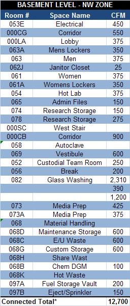
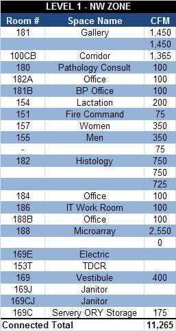
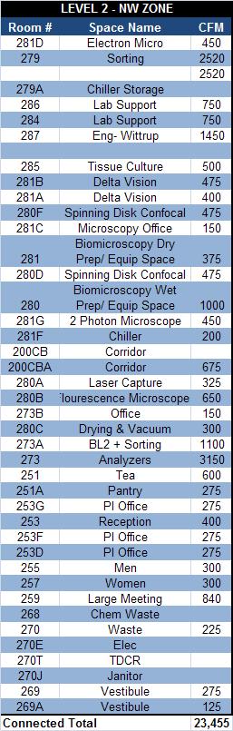
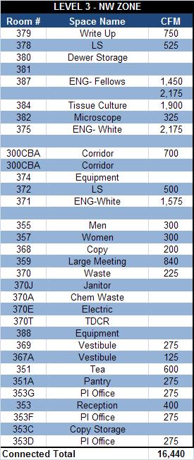
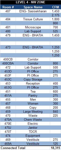
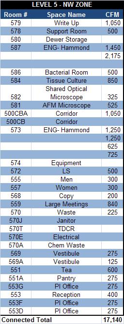
12 11 Level 2 was chosen to display a sample of the calculations performed for the spaces using the formulas shown on page 10. The buildings air supply is 100% outdoor air so therefore, the ventilation rate for all spaces is met due to the nature of the system. The West Shaft serves the West Zones of the building. For organizational purposes, the zone is displayed in NW and SW sections on Level 2. Table 4 Level 2 Northwest Ventilation Rate Sample Calculations

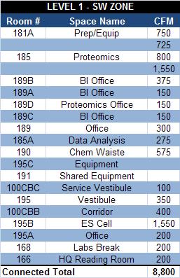
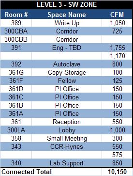
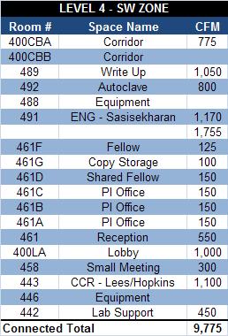
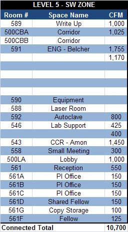
13 12 Table 5 Level 2 Southwest Ventilation Rate Sample Calculations These calculations result in some numbers that do not completely demonstrate the system accurately. A number of these spaces are designed to meet air change rates because it is a lab and research building. Also, all air that is being supplied to the spaces is 100% outdoor air, and contaminated air is being exhausted. Therefore, the indoor air quality requirements of ASHRAE Standard 62.1 are met throughout the building without an issue Conclusions The analysis of the designs compliance to ASHRAE Standard 62.1 was an overall success. The Standard is meant to ensure proper ventilation rates and acceptable indoor air quality. In this report, Sections 5 and 6 of the ASHRAE Standard made up the bulk of the analysis. Section 5 ensures that the systems and equipment are properly designed and located to achieve an acceptable indoor air quality. No areas of this section were found to be inadequate according to the requirements set forth by the ASHRAE Standard. In fact, many areas of the design went above and beyond, aiding in the goal of achieving LEED Gold Certification.


14 13 ASHRAE Standard Energy Design Evaluations Compliance Analysis The following section is an analysis of the compliance of the Koch Institute Design with the guidelines set forth by ASHRAE Standard The buildings envelope, HVAC systems, service water heating, power, lighting and electric motor efficiency will all be looked at in detail to check for compliance with the Standard. Section 5: Building Envelope Section Climate Figure 7 Exterior Elevation North The Koch Institute is located in Cambridge, Ma which is located in Zone 5 on the ASHRAE Climate Zone 5 which is depicted in green in the Figure 8 to the left. The Building Envelope Requirements are checked against the Table in ASHRAE Standard 90.1 which lists numerous requirements based on roof, walls (above and below grade), floors, slab-on-grade, opaque doors, and different fenestration arrangements. Figure 8 ASHRAE Climate Zone Map
 Figure 10 Exterior Wall Section (curtain wall) The Koch Institute is a non-residential building that was")
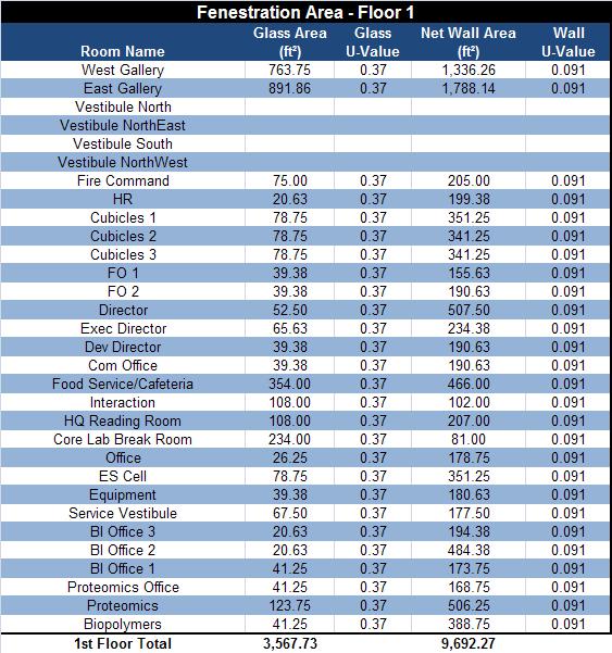
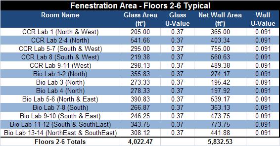
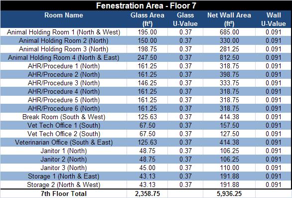
15 14 Section 5.5 Prescriptive Building Envelope Option Figure 9 Exterior Wall Section (metal paneling) Figure 10 Exterior Wall Section (curtain wall) The Koch Institute is a non-residential building that was analyzed under the Prescriptive Option of the Standard. The requirements of the building envelope were checked for compliance against Table Building Envelope Requirements for Climate Zones 5 (A,B,C) Table 6 Fenestration Area Compliance Table It is stated in Standard 90.1 that the fenestration area shall not exceed 40% of the gross wall area. Table-6 above shows that the design complies with this requirement. It was checked against individual floor areas, and though this is no the requirement, it is only off by 1% in floors 2-6.
16 15 Table 7 Building Envelope (Opaque Element) Requirements Compliance Table For the ASHRAE Climate Zone 5, the requirements for the envelope opaque element assembly are shown above in Table-7. It is also clear in Table-7 that the design values are within the required range set forth by Standard Table 8 Building Envelope (Fenestration) Requirements Compliance Table For the ASHRAE Climate Zone 5, the requirements for the envelope fenestration assembly are shown above in Table-8. It is also clear in Table-8 that the design values are within the required range set forth by Standard The Koch Institute s envelope design complies with all of the requirements in this section. The fenestration area Table 6 shows that each floor s fenestration area is only over the prescribed 40% of gross wall area. But as an overall façade the requirement is met by 3%, which is the actual requirement. In Appendix B, at the conclusion of this report, there are more detailed calculations of wall and fenestration area. It is possible that this 1% area could be a result of a miscalculation in those tables. Table 7 and Table 8 of this section show us that the Koch Institute s envelope also complies with ASHRAE requirements for Climate Zone 5. Therefore, the building is compliant with Section 5 of ASHRAE Standard 90.1 Energy Design Evaluation.
17 16 Section 6.2 Compliance Paths Section 6: Heating, Ventilation, and Air Conditioning For this analysis, ASHRAE provides two different compliance paths for which to compare your design. There is a Simplified Approach given in Section 6.3 and there is a Mandatory Provisions Approach given in Section 6.4. The simplified approach has a limitation of 25,000 ft 2 gross floor area that exceeded by the Koch Institute s 360,000 ft 2 gross floor area. Therefore, this compliance analysis will follow the Mandatory Provisions Approach laid out in Section 6.4. Section 6.4 Mandatory Provisions With the project still under construction, verification of equipment efficiencies and labeling of all mechanical equipment cannot yet be analyzed. The design does specify that each zone shall be individually controlled by thermostatic controls responding to temperature sensors within each space. The perimeter radiation heating system handling the increase building envelope loads is coupled with the air systems to reach the desired space conditions. All equipment that handles more than 10,000 CFM is operated with optimum start controls, ensuring that energy consumption is minimized and that space conditions are met. Section 6.5 Preventative Path The Koch Institute uses a combination Variable Air Volume and Constant Air Volume system to maximize zone control while still meeting pressurization requirements for specialty rooms. Therefore, when checking the fans against ASHRAES Fan Power Limitation in Table A, Constant volume was assumed. To calculate the Allowable Horsepower was calculated as follows: Allowable HP = CFM * The fan is then compliant if the Allowable HP > Nameplate HP and is given a YES or NO in the Compliant column. This process was performed for AHU, EAHU, Exhaust, Supply and Return Fans and results are given in the Tables on the following pages.

18 17 Table 9 AHU Fan Compliance Table


19 18 Table 10 Exhaust Fan Compliance Table Table 11 Supply Fan Compliance Table Table 12 Return Fan Compliance Table Though many of the fans shown in tables above are non-compliant based on the formula, many of them fall into the exception listed in Section a. This states that fans less than 6 bhp, where the first available motor larger than the break horsepower has a nameplate rating of within 50% of the bph, the next larger nameplate motor size may be selected. Also, by assuming a constant of , the fan compliance was held to a Constant Volume Specification though some may be VAV.
20 19 The Exhaust Air Energy Recovery System utilized in the factory built-up AHU and EAHU systems meets the requirements of having 70% or more outdoor air supply have at least 50% recovery effectiveness. The total enthalpy heat wheel recovers 75% of the energy difference to pre-heat and precool the outdoor air stream. Section 6.7 Submittals The Koch Institute is designed to achieve a LEED Gold Certification and therefore submittal of all proper documentation is strictly enforced. The system balancing and system commissioning is to be performed for LEED credits as specified. Section 7: Service Water Heating The heating source for the building is steam all year round which is provided from the MIT central energy plant through existing campus underground piping. The campus steam service is designed to be extended from a pre-existing tap at the SE corner of the adjacent State Center. Section 9: Lighting The lighting levels in the Koch Institute were designed to conform to the Illuminating Engineering Society s recommended values. Therefore the space breakdown of average lighting levels goes as follows: Laboratories: Laboratory support: Offices: Corridors: Conference Rooms: Toilets: Lobbies and Foyers: Animal Holding Rooms (Day/Night Cycle): Animal Holding Rooms (Working): 70 to 80 FC 50 to 60 FC 50 to 60 FC 20 to 30 FC 40 to 50 FC 20 to 30 FC 20 to 30 FC 30 to 35 FC 60 to 70 FC The Building Area Method was utilized in this case to analyze the power density of the multiple electrical loads throughout the building. Table 13 and Table 14 provide summaries of the building load and power density as calculated.


21 20 Table 13 Building Load Summary Table Table 14 Building Density Summary Table CONCLUSIONS The calculations and statements made throughout this analysis most strongly point out the David Koch Institute s success in complying with the ASHRAE Standard The design is very energy conscious as well as sophisticated, making this analysis difficult and tedious. It is possible that throughout the analysis something was overlooked or incorrectly assumed. It is also possible that some of these areas of non-compliance have been resolved seeing that the job is still under construction. That being said there were a number of non-compliant areas. The largest area of noncompliance can be seen in the Fan Power Compliance Section. But, of the 24 failed fans, 10 fall into the exception described in Section 6.5 and can therefore be considered acceptable. In conclusion, none of the fore mentioned discrepancies are exceedingly alarming and could be easily re-worked to fully comply with ASHRAE Standard Energy Design Evaluations.
22 21 APPENDIX A List of Tables and Figures
23 22 List of Figures Figure 1 AHU 1-4 and EAUH 1-4 Figure 2 AHU 7-10 and EAUH 7-10 Figure 3 AHU 5&6 and EAUH 5&6 Figure 4 Partial view of HVAC Penthouse Plan to show Outdoor Air Intake to large central system Figure 5 Taken from HVAC Roof Plan Figure 6 Drain Pan Seal Trap Figure 7 Exterior Elevation North Figure 8 ASHRAE Climate Zone Map Figure 9 Exterior Wall Section (metal paneling) Figure 10 Exterior Wall Section (curtain wall) List of Tables Table 1 Built Up Air Handling Unit Characteristics Table 2 Built Up Exhaust Air Handling Unit Characteristics Table 3 Air Handling Unit Filter Schedule (Pre & Final) Table 4 Level 2 Northwest Ventilation Rate Sample Calculations Table 5 Level 2 Southwest Ventilation Rate Sample Calculations Table 5 Level 2 Southwest Ventilation Rate Sample Calculations Table 6 Fenestration Area Compliance Table Table 7 Building Envelope (Opaque Element) Requirements Compliance Table Table 8 Building Envelope (Fenestration) Requirements Compliance Table Table 9 AHU Fan Compliance Table Table 10 Exhaust Fan Compliance Table Table 11 Supply Fan Compliance Table Table 12 Return Fan Compliance Table Table 13 Building Load Summary Table Table 14 Building Density Summary Table
24 23 APPENDIX B Supplemental Tables
25 24
26 25
27 26
28 27
29 28
30 29
31 30
32 31
33 32
Technical Assignment 3
 0 David H. Koch Institute for Integrative Cancer Research Senior Capstone Mechanical Option Technical Assignment 3 Mechanical Systems and Existing Conditions Report David H. Koch Institute for Integrative
8 5.11: Finned-Tube Coils and Heat Exchangers : Humidifiers and Water Spray Systems : Access for Inspection, Cleaning, and Maintenance
 Table of Contents 3 Executive Summary 4 Building Overview 5 Mechanical Systems Overview 6 ASHRAE Standard 62.1 2013 Evaluation 6 Section 5: Systems and Equipment 6 5.1: Ventilation Air Distribution 6 5.2:
EADQUARTERS. Technical Report One. Stephanie Kunkel Mechanical Option
 EADQUARTERS 707 N. Calvert St. Technical Report One ASHRAE Standard 62.1 Ventilation ASHRAE Standard 90.1 Energy Design Stephanie Kunkel www.engr.psu.edu/ae/thesis/portfolios/2011/slk5061 Mechanical Option
Table of Contents. List of Figures and Tables. Executive Summary: 3 ASHRAE Standard 62.1 Section 6 Analysis 7
 Army Reserve Center Newport, Rhode Island Technical Report One: ASHRAE Standard 62.1 Ventilat tion and Standard 90.1 Energy Design Evaluations October 4, 2010 2 Table of Contents Executive Summary: 3 ASHRAE
ASHRAE Standard 62 Ventilation Report Technical Assignment #1. Calvert Memorial Hospital Prince Frederick, MD
 ASHRAE Standard 62 Ventilation Report Technical Assignment #1 Prepared By: Holly Mawritz October 6, 2004 Table Of Contents: Executive Summary 2 Assumptions 3 Procedure 4 Sample Calculations 5 System and
Technical Report Rouse Boulevard. The Navy Yard Philadelphia, PA 19112
 Technical Report 1 201 Rouse Boulevard The Navy Yard Philadelphia, PA 19112 Nicholas W. Mattise Option: Mechanical;; Advisor: Dr. Miller September 23, 2013 Nicholas W. Mattise 1 of 22 Contents Executive
Hunter s Point South Intermediate School & High School
 Hunter s Point South Intermediate School & High School Long Island City, NY M E C H A N I C A L O P T I O N Technical Report One ASHRAE Standard 62.1-2007 and Standard 90.1-2007 Analysis By: Britt Kern
Mechanical Technical Report 1. ASHRAE Standard 62.1 Ventilation Compliance Evaluation
 Mechanical Technical Report 1 Standard 62.1 Ventilation Compliance Evaluation Lutheran Theological Seminary at Philadelphia The New Learning Center Prepared For: William P. Bahnfleth, Ph.D., P.E. Department
WORKSHOP VENTILATION- PSYCHROMETRICS-AHU
 Alkis Triantafyllopoulos Mechanical Engineer Member TEE, MASHRAE a.trianta@gmail.com WORKSHOP VENTILATION- PSYCHROMETRICS-AHU Based on ASHRAE 62 Purpose Set minimum Outdoor Air ventilation Rates Air Quality
Mechanical Redesign, Proposal Elizabeth C. Krauss Mechanical Option September 18, 2013
 Mechanical Redesign, Proposal Elizabeth C. Mechanical Option September 18, 2013 State Institute of Rehabilitation T e c h n i c a l R e p o r t I 1 Mechanical Redesign, Proposal... 0 Executive Summary...
August 15, 2013 Page 1 of 19
 Section C401 Application Compliance with C402, C403, C404 and C405 AND (either C406.2, C406.3 or C406.4) Compliance with C402, C403, C404 or C405 Section C402 Building Envelope (Climate Zone 5A) Space-Conditioning
UNIVERSITY OF MISSOURI Heating Ventilating and Air-Conditioning (HVAC) 2016 Q1
 2016 Q1") GENERAL: This section provides general standards for overall sizing and design of Heating, Ventilating, and Air Conditioning (HVAC) systems. Other sections contain specific standards for each system per
GENERAL: This section provides general standards for overall sizing and design of Heating, Ventilating, and Air Conditioning (HVAC) systems. Other sections contain specific standards for each system per
Technical Report 1. ASHRAE Standards 62.1, 170, and 90.1 Evaluation. Morton Hospital Expansion
 Technical Report 1 ASHRAE Standards 62.1, 170, and 90.1 Evaluation Morton Hospital Expansion Taunton, MA Courtney Millett Mechanical Option Advisor: Dr. Bahnfleth September 17, 2014 Millett Technical Report
AIR-CONDITIONING SYSTEMS AND APPLICATIONS. Abdullah Nuhait Ph D. King Saud University
 AIR-CONDITIONING SYSTEMS AND APPLICATIONS Abdullah Nuhait Ph D. King Saud University AIR-CONDITIONING SYSTEMS Earliest air conditioning system used only for heating (winter) Provided heated air for comfort
Mechanical System Redesign. Dedicated Outdoor Air System. Design Criteria
 Mechanical System Redesign Dedicated Outdoor Air System Design Criteria The outdoor air conditions used were for Philadelphia, Pennsylvania IAP at a 0.4% occurrence. The supply air conditions were developed
Technical Report Three
 Technical Report Three Existing Conditions for Mechanical Systems Contents Executive Summary...2 Building Overview...2 Mechanical Systems Overview...2 Mechanical System...3 Outdoor & Indoor Design Conditions...3
COMcheck Software Version Mechanical Compliance Certificate
 COMcheck Software Version 4.0.8.1 Mechanical Compliance Certificate Project Information Energy Code: Location: Climate Zone: Project Type: 90.1 (2013) Standard Buda, Texas 2a New Construction Construction
Senior Thesis Centre Community Hospital East Wing Addition - Proposal Keith Beidel Mechanical Option 12/05/02 1
 Table of Contents Page Number(s) Executive Summary 2 Project Background 3 Proposed Depth Alternatives 4 Proposed Depth Redesign 5-7 Justification of Proposed Depth Redesign 8 Proposed Breath Redesign 9
Technical Assignment 1
 Technical Assignment 1 ASHRAE Standard 62.1 2007 Ventilation Compliance Evaluation Prepared For: Dr. James D. Freihaut, PhD Department of Architectural Engineering The Pennsylvania State University Prepared
4. OVERVIEW OF MECHANICAL SYSTEM
 4. OVERVIEW OF MECHANICAL SYSTEM The 87,000 SF SLCC is served by six (6) Trane M-Series Climate Changer Air Handing Units (AHUs). Each unit serves a distinct zone within the facility that is unique in
Mechanical Compliance Certificate
 COMcheck Software Version 4.0.7.0 Mechanical Compliance Certificate Project Information Energy Code: Location: Climate Zone: Project Type: 90.1 (2013) Standard Austin, Texas 2a (weather data: TBD) New
Existing Mechanical System Operation
 majority of the air handlers. There are louvers along the north side of the building that allow for outdoor air to come in and feed the air handlers. On levels 4-8 the research laboratories are variable
CARRIER edesign SUITE NEWS. Modeling 100% OA Constant Volume Air Systems. Volume 6, Issue 1. Page 1 Modeling 100% OA Constant Volume Air Systems
 Volume 6, Issue 1 CARRIER edesign SUITE NEWS Modeling 100% OA Constant Volume Air Systems This article provides an overview of how to model a stand-alone constant air volume (CAV) 100% OA system in HAP.
CITY OF DANA POINT. COMMUNITY DEVELOPMENT, BUILDING AND SAFETY Golden Lantern, Suite 209 Dana Point, CA
 CITY OF DANA POINT COMMUNITY DEVELOPMENT, BUILDING AND SAFETY 33282 Golden Lantern, Suite 209 Dana Point, CA 92629 949 248 3594 www.danapoint.org INDOOR AIR QUALITY B011 AIR 2013 CALIFORNIA CODES CODE
CALIFORNIA MECHANICAL CODE OVERVIEW OF 2016 UPDATES CHANGES AND RAMIFICATIONS
 CALIFORNIA MECHANICAL CODE OVERVIEW OF 2016 UPDATES CHANGES AND RAMIFICATIONS Presented to: Presented by: Sargon Ishaya, PE www.pragmaticprofessionalengineers.com Introduction Today s Agenda Overview Review
Underfloor Air Distribution:
 Underfloor Air Distribution: An underfloor air distribution system utilizes a plenum space between the structural slab and the underside of a raised floor to distribute the conditioned air to the room.
Element Z General Design Requirements Existing Facilities Information
 Charles M. LeMaistre PART 1 - INTRODUCTION 1.01 OVERVIEW A. This Section provides general information for building systems and components. B. Refer to the Owner s Design Guideline Elements A though G and
HVAC 101. H V A C S y s t e m s
 H V A C 1 0 1 S y s t e m s Introduction & Overview Should you care? Mechanical System Types Components & operation Popular Application Key Issues and Design Considerations System Comparisons First Cost
AIRSIDE COMPONENTS AND SYSTEMS
 Ventilation: Outdoor air (OA) ventilation shall be introduced into each occupied building space in compliance with ASHRAE Standard 62. Adequate additional OA capability is needed to keep buildings under
COMcheck Software Version Mechanical Compliance Certificate
 COMcheck Software Version 4.0.6.2 Mechanical Compliance Certificate Project Information Energy Code: Location: Climate Zone: Project Type: 90.1 (2007) Standard HALCYON Bldg. 400 Alpharetta, Georgia 3a
National Institutes of Health Building 37 Modernization Bethesda, Maryland MECHANICAL DEPTH EXISTING MECHANICAL SYSTEM
 MECHANICAL DEPTH EXISTING MECHANICAL SYSTEM The need to maintain occupancy during the renovation and the strict NIH Design Guidelines were the main driving forces behind the design. The mechanical engineering
CHAPTER 4. HVAC DELIVERY SYSTEMS
 CHAPTER 4. HVAC DELIVERY SYSTEMS 4.1 Introduction 4.2 Centralized System versus Individual System 4.3 Heat Transfer Fluids 4.4 CAV versus VAV Systems 4.5 Common Systems for Heating and Cooling 4.6 Economizer
HAP e-help. Modeling Induction Beams in HAP v4.8 QB TIP 001
 This HAP e-help provides a high-level overview of induction beams, how they work and how to model them in HAP 4.8 (and later versions). The first half of the article explains how induction beams work.
FINAL THESIS REPORT. Oklahoma University Children s Medical Office Building OKLAHOMA UNIVERSITY CHILDREN S MEDICAL OFFICE BUILDING
 FINAL THESIS REPORT Oklahoma University Children s Medical Office Building Oklahoma City, Oklahoma A l e c T. C a n t e r M e c h a n i c a l O p t i o n B a c h e l o r o f A r c h i t e c t u r a l E
AIR DISTRIBUTION. C. Section Building Automation and Control System Guidelines. D. Section Fire Alarm System & Detection Systems
 233100 AIR DISTRIBUTION PART 1: GENERAL 1.01 RELATED SECTIONS A. Section 230700 HVAC Insulation B. Section 237300 Air Handling C. Section 230900 Building Automation and Control System Guidelines D. Section
1.1 This section applies to air handling units for HVAC Systems.
 AIR HANDLING UNITS GENERAL INFORMATION 1.1 This section applies to air handling units for HVAC Systems. DESIGN REQUIREMENTS 2.1 Design Criteria a. The decision to use modular central station air handling
7. MECHANICAL SYSTEM DESIGN
 7. MECHANICAL SYSTEM DESIGN The second primary topic of this thesis is to investigate the application of a dedicated outdoor air system (DOAS) to the SLCC. The stated goals for this thesis of improved
UFAD and Displacement Ventilation. Dan Int-Hout, FASHRAE Chief Engineer Krueger Richardson, Texas
 UFAD and Displacement Ventilation Dan Int-Hout, FASHRAE Chief Engineer Krueger Richardson, Texas UFAD and DV Systems, Objectives: Understand Differences between: Well Mixed, Partially Stratified and Fully
1 - This title will copy onto other forms Date
 2015 Washington State Energy Code Compliance Forms for Commercial, R2 and R3 over 3 stories and all R1 Mechanical Summary MECH-SUM Project Title: 1 - This title will copy onto other forms Date 1/1/2015
Comfort and health-indoor air quality
 Comfort and health-indoor air quality 1 The human body has a complicated regulating system to maintain the human body temperature constant most of the time, which is 98.6 F (36.9 C) regardless of the environmental
COMcheck Software Version Review Mechanical Compliance Certificate
 COMcheck Software Version 4.0.7.2 Review Mechanical Compliance Certificate Section 1: Project Information Energy Code: 2014 Oregon Energy Efficiency Specialty Code Project Title: Benton County Health Project
UNIVERSITY OF MISSOURI Central Station Air-Handling Units March
 GENERAL: 1. This section provides criteria for the design and installation of air handling units. DESIGN GUIDELINES: Design General 1. Location 1.1. For new construction, and existing buildings where possible,
INTRODUCTION TO: ASHRAE STANDARD 90.1, HVAC System Requirements for Reducing Energy Consumption in Commercial Buildings
 INTRODUCTION TO: ASHRAE STANDARD 90.1, 2013 HVAC System Requirements for Reducing Energy Consumption in Commercial Buildings Rocky Mountain ASHRAE Technical Conference, April 29, 2016 SEAN BEILMAN, P.E.,
HVAC Mandatory Provisions Part II, Page 1
 HVAC Mandatory Provisions Part II, Page 1 Mandatory Equipment Efficiency Worksheet (6.4.1.1) System Equipment Type Size Category (Tables 6.8.1A through K) Sub-Category or Rating Condition Units of Efficiency
COMcheck Software Version Mechanical Compliance Certificate
 COMcheck Software Version 4.0.3.0 Mechanical Compliance Certificate Section 1: Project Information Energy Code: 2014 Oregon Energy Efficiency Specialty Code Project Title: AHSC (Asian Heal Service Center
COMcheck Software Version Mechanical Compliance Certificate
 COMcheck Software Version 3.8.2 Mechanical Compliance Certificate 90.1 (2007) Standard Section 1: Project Information Project Type: New Construction Project Title : Rudy's Star Motors Construction Site:
Element Z General Design Requirements Existing Facilities Information
 PART 1 - INTRODUCTION 1.01 OVERVIEW A. This Section provides general information for building systems and components. B. Refer to the Owner s Design Guideline Elements A though G and Element Z for technical
SUPPORTING DOCUMENT RESIDENTIAL ENERGY CODE WORKSHEET (2015) EFFECTIVE JANUARY 1, 2017
 EFFECTIVE JANUARY 1, 2017") SUPPORTING DOCUMENT RESIDENTIAL ENERGY CODE WORKSHEET (2015) EFFECTIVE JANUARY 1, 2017 The Residential Energy Code Worksheet is a tool to help you plan your energy code needs for new or remodeled homes,
SUPPORTING DOCUMENT RESIDENTIAL ENERGY CODE WORKSHEET (2015) EFFECTIVE JANUARY 1, 2017 The Residential Energy Code Worksheet is a tool to help you plan your energy code needs for new or remodeled homes,
Union County Vocational - Technical Schools Scotch Plains, New Jersey
 SECTION 230593 - TESTING, ADJUSTING, AND BALANCING FOR HVAC PART 1 - GENERAL 1.1 SUMMARY A. Section Includes: 1. Balancing Air Systems: a. Constant-volume air systems. b. Variable-air-volume systems. 2.
1080 Marina Village Parkway, Suite 501 Alameda, CA (510) Fax (510) HVAC DESIGN INTENT
 Fax (510) HVAC DESIGN INTENT") Taylor Engineering 1080 Marina Village Parkway, Suite 501 Alameda, CA 94501-1142 (510) 749-9135 Fax (510) 749-9136 LLC HVAC DESIGN INTENT PART 1 - GENERAL 1.1 Overview A. The project consists of a 3-story
Taylor Engineering 1080 Marina Village Parkway, Suite 501 Alameda, CA 94501-1142 (510) 749-9135 Fax (510) 749-9136 LLC HVAC DESIGN INTENT PART 1 - GENERAL 1.1 Overview A. The project consists of a 3-story
Appendix 13. Categories of Cooling and Heating systems
 EcoShopping - Energy efficient & Cost competitive retrofitting solutions for Shopping buildings Co-funded by the European Commission within the 7 th Framework Programme. Grant Agreement no: 609180. 2013-09-01
Dehumidifying with Dedicated Outdoor Air
 Dehumidifying with Dedicated Outdoor Air System Configurations Figure 71. Configurations for dedicated outdoor-air systems A dedicated outdoor-air handler separately filters, cools, dehumidifies, heats,
THE PENNSYLVANIA STATE UNIVERSITY SCHREYER HONORS COLLEGE DEPARTMENT OF ARCHITECTURAL ENGINEERING RUTGERS ACADEMIC BUILDING ANDREW KOFFKE SPRING 2015
 THE PENNSYLVANIA STATE UNIVERSITY SCHREYER HONORS COLLEGE DEPARTMENT OF ARCHITECTURAL ENGINEERING RUTGERS ACADEMIC BUILDING ANDREW KOFFKE SPRING 2015 A thesis submitted in partial fulfillment of the requirements
ASHRAE WILL GIVE YOU THE WORLD. This ASHRAE Distinguished Lecturer is brought to you by the Society Chapter Technology Transfer Committee
 ASHRAE WILL GIVE YOU THE WORLD This ASHRAE Distinguished Lecturer is brought to you by the Society Chapter Technology Transfer Committee Complete the Distinguished Lecturer Event Summary Critique CTTC
Tighe&Bond. Groton Heights School Mechanical Evaluation. 1 Existing Conditions. 1.1 Water Service Entrance
 Groton Heights School Mechanical Evaluation TO: FROM: Amy Vaillancourt, Project Manager Harley Langford, Project Manger Jason Curtis, P.E. DATE: February 24, 2016; Revised May 31, 2016 On Monday, December
Challenges and Methods of Estimating a Conceptual HVAC Design
 Challenges and Methods of Estimating a Conceptual HVAC Design ABSTRACT In any conceptual HVAC design, estimators are faced with the challenge of trying to capture all of the pieces that complete a system.
Raised Access Floor - (AE Breadth Area)
") Raised Access Floor - (AE Breadth Area) Currently, the Plaza has a raised access flooring system on both the 7 th and 8 th floors. The 8 th floor is designed with an independent HVAC system utilizing an
Raised Access Floor - (AE Breadth Area) Currently, the Plaza has a raised access flooring system on both the 7 th and 8 th floors. The 8 th floor is designed with an independent HVAC system utilizing an
COMMERCIAL HVAC EQUIPMENT Indoor Self-Contained Units
 COMMERCIAL HVAC EQUIPMENT Indoor Self-Contained Units Technical Development Program Technical Development Programs (TDP) are modules of technical training on HVAC theory, system design, equipment selection
Energy Savings Potential of Passive Chilled Beam System as a Retrofit Option for Commercial Buildings in Different Climates
 Purdue University Purdue e-pubs International High Performance Buildings Conference School of Mechanical Engineering 2014 Energy Savings Potential of Passive Chilled Beam System as a Retrofit Option for
Chilled beam technology overview John Woollett 1, Jonas Åkesson 2 Swegon AB 1,2
 Chilled beam technology overview John Woollett 1, Jonas Åkesson 2 Swegon AB 1,2 john.woollett@swegon.se, jonas.akesson@swegon.se SUMMARY The main focus of the paper will be on active beam technology regarding
Design Considerations For Dedicated OA Systems BY HUGH CROWTHER, P.ENG, MEMBER ASHRAE; YI TENG MA, ASSOCIATE MEMBER ASHRAE
 ASHRAE www.ashrae.org. Used with permission from ASHRAE Journal. This article may not be copied nor distributed in either paper or digital form without ASHRAE s permission. For more information about ASHRAE,
Pharmaceutical Facility Design
 PhEn-602 Pharmaceutical Facility Design J. Manfredi Notes 9A PhEn-602 J. Manfredi 1 Primary & Secondary HVAC units Primary Primary air handling unit arrangement: One unit is responsible for all of the
2009 IECC Commercial Mechanical Requirements
 BUILDING ENERGY CODES UNIVERSITY 2009 IECC Commercial Mechanical Requirements Ken Baker PNNL-SA-66171 Learning(Objec-ves(( ( 1. Find(minimum(equipment(efficiency(requirements( and(recite(at(least(3(common(terms(for(measuring(
Adding More Fan Power Can Be a Good Thing
 This article was published in ASHE Journal, May 14. Copyright 14 ASHE. Posted at www.ashrae.org. This article may not be copied and/or distributed electronically or in paper form without permission of
ASHRAE Region VI CRC Track III: Session 3 Ventilation Energy Recovery. Steven T. Taylor, PE Principal Taylor Engineering
 ASHRAE Region VI CRC Track III: Session 3 Ventilation Energy Recovery Steven T. Taylor, PE Principal Taylor Engineering This program is registered with the AIA/CES for continuing professional education.
GARCIA GALUSKA DESOUSA Consulting Engineers
 L#57295/Page 1/July 21, 2017 HVAC SYSTEMS NARRATIVE REPORT The following is the HVAC system narrative, which defines the scope of work and capacities of the HVAC system as well as the Basis of Design.
Performance Rating of Active Chilled Beams
 AHRI Standard 1241 (SI) 2016 Standard for Performance Rating of Active Chilled Beams IMPORTANT SAFETY RECOMMENDATIONS AHRI does not set safety standards and does not certify or guarantee the safety of
Computing Services Center
 Continuous Commissioning Report for the Computing Services Center Building #516 Submitted to: Utilities Energy Office Physical Plant Department Texas A&M University Prepared by: Energy Systems Laboratory
Brown University Revised August 3, 2012 Facilities Design & Construction Standards SECTION AIR HANDLING UNITS
 SECTION 23 70 00 AIR HANDLING UNITS PART 1. GENERAL 1.1 Section includes air-handling units to 15,000 cfm and accessories. 1.2 Related Sections 1 : A. Division 01 - Brown University Standard for Narragansett
ERRATA SHEET FOR ANSI/ASHRAE/IES STANDARD (I-P Edition) Energy Standard for Buildings Except Low-Rise Residential Buildings.
 Energy Standard for Buildings Except Low-Rise Residential Buildings.") ERRATA SHEET FOR ANSI/ASHRAE/IES STANDARD 90.1-2013 (I-P Edition) Energy Standard for Buildings Except Low-Rise Residential Buildings July 7, 2017 The corrections listed in this errata sheet apply to ANSI/ASHRAE/IES
ERRATA SHEET FOR ANSI/ASHRAE/IES STANDARD 90.1-2013 (I-P Edition) Energy Standard for Buildings Except Low-Rise Residential Buildings July 7, 2017 The corrections listed in this errata sheet apply to ANSI/ASHRAE/IES
Element D Services Heating, Ventilating, and Air Conditioning
 Air Handling Distribution PART 1 - GENERAL 1.01 OVERVIEW A. This section describes criteria for design of facility air handling distribution systems, including air handlers, ductwork, ductwork accessories,
DEHUMIDIFICATION: Ice Arena Application & Product Guide. Design, construct and operate to control indoor humidity in ice rinks
 DEHUMIDIFICATION: Ice Arena Application & Product Guide Design, construct and operate to control indoor humidity in ice rinks Munters is the world leader in dehumidification Munters is the largest manufacturer
COMcheck Software Version Mechanical Compliance Certificate
 COMcheck Software Version 4.0.4. Mechanical Compliance Certificate Project Information Energy Code: Location: Climate Zone: Project Type: 205 IECC Dallas, Texas 3a New Construction Construction Site: 56
ASHRAE/IESNA Standard
 ASHRAE/IESNA Standard 90.1-1999 An inside look at the requirements of Standard 90.1-1999 Energy Standard for Building Except Low-Rise Residential Building Mick Schwedler, PE Sr. Principal Applications
COMcheck Software Version Interior Lighting Compliance Certificate
 Section 1: Project Information Energy Code: 2009 IECC Project Type: New Construction COMcheck Software Version 4.0.2.8 Interior Lighting Compliance Certificate Construction Site: Owner/Agent: Designer/Contractor:
SESSION Michigan Energy Code (MEC) Update (3 Technical) Per SMACNA Standard (TAB, Duct Design) and ASHRAE ( ) ASHRAE Detroit Members:
 Update (3 Technical) Per SMACNA Standard (TAB, Duct Design) and ASHRAE ( ) ASHRAE Detroit Members:") SESSION 1-2015 Michigan Energy Code (MEC) Update (3 Technical) Per SMACNA Standard (TAB, Duct Design) and ASHRAE (90.1.2013) ASHRAE Detroit Members: AM Session is eligible for (X) Professional Development
SESSION 1-2015 Michigan Energy Code (MEC) Update (3 Technical) Per SMACNA Standard (TAB, Duct Design) and ASHRAE (90.1.2013) ASHRAE Detroit Members: AM Session is eligible for (X) Professional Development
Mechanical Technical Report 3. Mechanical Systems Existing Conditions Evaluation
 Mechanical Technical Report 3 Lutheran Theological Seminary at Philadelphia The New Learning Center Prepared For: William P. Bahnfleth, Ph.D., P.E. Department of Architectural Engineering Pennsylvania
DIVISION 15 MECHANICAL
 DIVISION 15 MECHANICAL A. GENERAL DESIGN CONDITIONS 1. Design occupied spaces to maintain 72 F and a space dew point temperature not to exceed 55 F. 2. Design classroom and office space buildings with
ASHRAE JOURNAL ON REHEAT
 Page: 1 of 7 ASHRAE JOURNAL ON REHEAT Dan Int-Hout Chief Engineer Page: 2 of 7 Overhead Heating: A lost art. March 2007 ASHRAE Journal Article Dan Int-Hout Chief Engineer, Krueger VAV terminals provide
Don t Turn Active Beams Into Expensive Diffusers
 This article was published in ASHRAE Journal, April 2012. Copyright 2012 American Society of Heating, Refrigerating and Air-Conditioning Engineers, Inc. Posted at www.ashrae.org. This article may not be
TECHNICAL REPORT 3: Mechanical Systems and Existing Conditions. Michael Morder Mechanical Option Advisor: Dr. William Bahnfleth
 TECHNICAL REPORT 3: Mechanical Systems and Existing Conditions Michael Morder Mechanical Option Advisor: Dr. William Bahnfleth INOVA South Patient Tower Falls Church, VA November 16, 2011 Table of Contents
Case Study: Furman University Charles H. Townes Center for Science. Michael K. Mantai, PE, CCP President System WorCx
 Case Study: Furman University Charles H. Townes Center for Science Michael K. Mantai, PE, CCP President System WorCx AIA Quality Assurance Learning Objectives 1. Case study example of Chilled Beam technology
Cleveland Clinic Design Standards MECHANICAL SYSTEMS DESIGN GUIDELINES HVAC AIR DISTRIBUTION PART I - GENERAL 1.1 SUMMARY
 PART I - GENERAL 1.1 SUMMARY A. This section addresses the general requirements for air handling distribution systems, including air handlers, ductwork, ductwork accessories, terminal units, air devices,
b.) Technical Information:
 Technical Information:") Section VI- Strategies a.) Summary: It is important for new construction designers to consider the heating, ventilation, and air conditioning needs within a building. There are many different systems,
Section VI- Strategies a.) Summary: It is important for new construction designers to consider the heating, ventilation, and air conditioning needs within a building. There are many different systems,
Impacts of Optimized Cold & Hot Deck Reset Schedules on Dual Duct VAV Systems - Theory and Model Simulation
 Impacts of Optimized Cold & Hot Deck Reset Schedules on Dual Duct VAV Systems - Theory and Model Simulation Mingsheng Liu, Ph.D., P.E. Energy Systems Laboratory Texas A&M University College Station, Texas
BUILDING VENTILATION GUIDE FOR LG HVAC SYSTEM INSTALLATION
 BUILDING VENTILATION GUIDE FOR LG HVAC SYSTEM INSTALLATION PROPRIETARY DATA NOTICE This document, as well as all reports, illustrations, data, information, and other materials are the property of LG Electronics
PINNACLE SERIES DEDICATED OUTDOOR AIR SYSTEM ENERGY EFFICIENT DEHUMIDIFICATION
 ENERGY EFFICIENT DEHUMIDIFICATION PINNACLE SERIES DEDICATED OUTDOOR AIR SYSTEM Provides a very high degree of latent cooling using only a minimal amount of conventional cooling input Substantial energy
RIVER VUE APARTMENTS, PITTSBURGH, PA
 Technical Report 1 ASHRAE Standards 62.1 and 90.1 Design Evaluations RIVER VUE APARTMENTS, PITTSBURGH, PA September 23, 2011 Authored by: Laura C. Pica Adviser: Stephen Treado Technical Report 1 ASHRAE
Harrington Tower Building
 Continuous Commissioning Report For the Harrington Tower Building Building #435 Submitted to: Utilities Energy Office Physical Plant Department Texas A&M University Prepared by: Energy Systems Laboratory
Technical Information
 How to design easily a smoke management system? Mechanical smoke extraction for enclosed car park Car park: specificity of the smoke extraction system Car parks are nowadays integrated directly inside
SECTION HVAC TABLE OF CONTENTS PART 1 - SYSTEM DESCRIPTION / OUTLINE SPECIFICATIONS FILED SUB BID PROJECT OVERVIEW...
 SECTION 230001 TABLE OF CONTENTS SECTION 230001 PART 1 - SYSTEM DESCRIPTION / OUTLINE SPECIFICATIONS... 1 1.00 FILED SUB BID... 1 1.01 PROJECT OVERVIEW... 2 1.02 DESIGN CRITERIA... 4 1.03 CODE ISSUES...
Andrea Borowski The Pennsylvania State University University Park, PA November 11, 2002 Consultant: Dr. Bahnfleth Technical Assignment M-3
 Existing System Evaluation Executive Summary The MBNA Career Services Center is a 44,000 square foot, 4-story office type building at Penn State University, University Park Campus. The building is located
Urbana Free Library HVAC Analysis. Prepared for the Urbana Free Library. Prepared by Paul Boland, P.E., and Nathan Alderman, E.I.T.
 Urbana Free Library HVAC Analysis Prepared for the Urbana Free Library Prepared by Paul Boland, P.E., and Nathan Alderman, E.I.T. Report Dated August 8, 2016 1. Introduction The Urbana Free Library is
Redesign of Bennett Hall HVAC System
 MEE 488 April 18, 2006 Redesign of Bennett Hall HVAC System Greg Andreasen Michael Chicoine Florent Hohxa Jason Jacobe Mechanical Engineering, University of Maine, Orono ME 04473, USA ABSTRACT Our task
City of Duluth Festival Center 04/25
 SECTION 230593 - TESTING, ADJUSTING, AND BALANCING FOR HVAC PART 1 - GENERAL 1.1 RELATED DOCUMENTS A. Drawings and general provisions of the Contract, including General and Supplementary Conditions and
B. Use UT Austin specifications and equipment schedule format for HVAC equipment where available.
 PART 1: GENERAL 1.01 General Requirements A. This standard is intended to provide useful information to the Professional Service Provider (PSP) to establish a basis of design. The responsibility of the
MultiFamily Ventilation Updates: ASHRAE 62.2, Best Practices and Practical Applications RESNET Conference Atlanta, GA
 MultiFamily Ventilation Updates: ASHRAE 62.2, Best Practices and Practical Applications 2014 RESNET Conference Atlanta, GA Ray Ivy and Mike Barcik Southface 1 About Southface 2 Topics Covered How to use
IAQ Building Education and Assessment Model (I-BEAM)
") Heating, Ventilation, and Airconditioning (HVAC) Text Modules IBEAM IAQ in L... http://www.epa.gov/iaq/largebldgs/ibeam/text/hvac.html Page 1 of 6 10/21/08 IAQ in Large Buildings http://www.epa.gov/iaq/largebldgs/ibeam/text/hvac.html
Heating, Ventilation, and Airconditioning (HVAC) Text Modules IBEAM IAQ in L... http://www.epa.gov/iaq/largebldgs/ibeam/text/hvac.html Page 1 of 6 10/21/08 IAQ in Large Buildings http://www.epa.gov/iaq/largebldgs/ibeam/text/hvac.html
SECTION I: EXISITNG SYSTEM AND PROPOSED SYSTEMS
 SECTION I: EXISITNG SYSTEM AND PROPOSED SYSTEMS Original Design: Traditional Central Heating and Cooling Heating and Cooling System Schematic Original Design Ventilation Schematic: Existing system summary:
MECHANICAL VENTILATION
 MECHANICAL VENTILATION Natural and Mechanical Systems Four (4) possible combinations of natural and mechanical ventilations tions are as follows; Natural inlet and outlet; utilizing open able windows,