SPLIT-TYPE AIR CONDITIONER
|
|
|
- Shana Kelly
- 6 years ago
- Views:
Transcription


1 SPLIT-TYPE AIR CONDITIONER MODEL CODE INDOOR UNIT AR09MSWXCWKNCV AR12MSWXCWKNCV OUTDOOR UNIT AR09MSWXCWKXCV AR12MSWXCWKXCV AIR CONDITIONER CONTENTS 1. Precautions 2. Pr cations 3. Alignment and Adjustments 4. Disassembly and Reassembly AR09MSWXCWKNCV AR12MSWXCWKNCV 5. ASSY CONTROL 6. Electrical Parts List 7. Wiring Diagram 8. PCB Diagram 9. Operating Instructions AR09MSWXCWKXCV AR12MSWXCWKXCV 10. Troubleshooting 11.Block Diagram 12. Reference Sheet
2 Contents 1. Precautions Installing the air conditioner Power supply and circuit breaker During operation Disposing of the unit Others The Feature of Product Alignment and Adjustments Test Mode Display Error and Check Method Setting Option Setup Method EEPROM Download Disassembly and Reassembly Indoor Unit Outdoor Unit ASSY CONTROL ASSY KIT CODE DB B ASSY CONTROL OUT WIFI Case Electrical Parts List INDOOR MAIN PCB CODE DB A OUTDOOR MAIN PBA CODE DB D INDOOR DISPLAY PBA CODE DB A Wiring Diagram Indoor Unit Outdoor Unit 7-2 1
3 Contents 8. PCB Diagram INDOOR MAIN PCB CODE DB A OUTDOOR PCB DISPLAY PCB SUB PCB-RECEIVE Wire connecting the indoor unit terminal blocks Operating Instructions Name of Each Part Wireless Remote Control-Buttons and Display Troubleshooting Items to be checked First Communication Error Communication Error Indoor temperature sensor Error Indoor fan motor speed detecting error (BLDC fan) Outdoor temperature sensor error Outdoor Cond temperature sensor error Outdoor Discharge temperature sensor error Operation condition secession error EEPROM error/otp error Outdoor Fan motor error Compressor starting error Compressor wire missing error/rotation error Current sensor error/input current sensor error O.C(Over Current) error No power outdoor (Initial Diagnosis) (Not displayed) When the Up/Down, Left/Right, Grill louver motor does not operate (Initial Diagnosis) (Not displayed) When the remote control is not receiving Smart Install error Outdoor OLP over temperature error (One way Inverter Only) Outdoor Discharge over temperture error PCB Inspector Method Pre-inspection Notices Inspection procedure Indoor detailed inspection procedure Outdoor detailed inspection procedure Block Diagram Indoor unit Outdoor unit Reference Sheet Low Refrigerant Pressure Distribution Pressure & Capacity mark Q & A for Non-trouble Cleaning /Filter Change Installation Installation Diagram of Indoor Unit and Outdoor Unit Reference sheet

4 1. Precautions 1-1 Installing the air conditioner Uses should not install the air conditioner by themselves. Ask the dealer or authorized company to install the air conditioner except window-type air conditioner in U.S.A and Canada. If you don't install the air conditioner properly, it may cause a fire, a water leakage or an electric shock. You must install the air conditioner according to the national wiring regulations and safety regulations. Install the indoor unit higher than 2.5m from the floor to avoid the injury caused by the operation of the fan. (except the window-type air conditioner) The manufacturer is not responsible for any accidents or injury caused by an incorrect installation. When installing the built-in type air conditioner, keep all electric cables such as the power cable and the connection cord in pipes, ducts, or cable channels to protect them from the danger of impact or any other incidents. 1-2 Power supply and circuit breaker If the power cord of the air conditioner is damaged, it must be replaced by the manufacturer or a qualified person in order to avoid a hazard. The air conditioner must be plugged into an independent circuit if applicable or connect the power cable to the auxiliary circuit breaker. An all pole disconnection form the power supply must be incorporated in the fixed wiring with a contact opening of>3mm. Do not extend an electric cord to the air conditioner. The air conditioner must be plugged in after you complete the installation. 1-3 During operation Do not repair the air conditioner at your discretion. It is recommended to contact a service center directly. Never spill any kind of liquid on the air conditioner. If this happens, turn off the air conditioner and contact an authorized service center. Do not insert anything between the airflow blades to prevent damage of the inner fan and consequent injury. Keep children away from the air conditioner. Do not place any obstacles in front of the air conditioner. Do not spray any kind of liquid into the indoor unit. If this happens, turn off the air conditioner and contact a service center. Make sure that the air conditioner is well ventilated at all times. Do not place a cloth or other materials over it. Remove the batteries if you don't use the remote control for a long time. (If applicable) Use the remote control within 7 meters from the indoor unit. (If applicable) 1-1
5 1-4 Disposing of the unit Before the throwing out the air conditioner, remove the batteries from the remote control. When you dispose of the air conditioner, consult your dealer. If pipes are removed incorrectly, refrigerant may blow out and cause air pollution. When it contacts with your skin, it can cause skin injury. The package of the air conditioner should be recycled or disposed of properly for environmental reasons. 1-5 Others Never store or load the air conditioner upside down or sideways to prevent the damage to the compressor. Young children or infirm persons should be always supervised when they use the air conditioner. Max current is measured according to IEC standard for safety. Current is measured according to ISO standard for energy efficiency. 1-2
6 2. Product Specifications 2-1 The Feature of Product 2-step cooling 2-step cooling function will quickly cool the room to reach the desired temperature and then it will adjust the fan speed and ai ow direction automatically to help you stay comfortable and refreshed. Fast cooling If you want the strong and cool air, just select Fast function! It will get you the strongest air! Comfort cooling If you want the comfortable and refreshing air, Comfort function will spread the cool air indirectly to you, so that you can stay comfortable. Single User Use the Single User function when you re along at home. Aside from energy savings from the inverter technology, the Single User Mode will further minimize your energy consumption and reduce your electricity bill by adjusting the maximum operating capacity of the compressor. Easy Filter function function will allow you to have deep, good night s sleep by adjusting the Smart Install When the installation is done, your product will examine itself through trial operation to check if it was installed properly. Easy Installation It s so easy to install! You can easily hang the product on the wall and connect the pipes and wires by opening the cover on the bottom of the product. Now you won t have to tilt the product to connect the pipe and the wires!
7 AR09MSWXCWKNCV AR12MSWXCWKNCV Model Rating Mode Unit Wall-mounted Wall-mounted T1 Cool Btu/h Capacity T3 Cool Btu/h - - Heat T1 Cool W Power Input T3 Cool W - - Heat T1 Cool A Current T3 Cool A - - Heat EER W/W Efficiency - - COP W/W Dehumidifying l/hr Platform Evap IDU Main - - F-RAC-06 (Wind-Free) 7, ( 2R*10S+1R*6S )*635mm, H1.3, N.G.S, 1by2 F-RAC-06 (Wind-Free) 7, ( 2R*10S+1R*6S )*635mm, H1.3, N.G.S, 1by2 ODU Sub - - SI 7, ( 2R*4S+1R*4S )*635mm, H1.3, N.G.S : (F03-4) SI 7, ( 2R*4S+1R*4S )*635mm, H1.3, N.G.S : (F03-4) COND Main - Motor In IDU - DB B DB B ODU - DB A DB A Power Supply V/Hz/ /50/ /50/1 Climate Class - T1 T1 Noise Net Size (W*D*H) Weight Operation range IDU UT,T IDU IDU Cooling db mm kg IDU 16 C~32 C 16 C~32 C ODU *265* *265* ODU UT,T ODU ODU Heating db mm kg IDU 8 C to 27 C 8 C to 27 C ODU *545* *545*
8 2-3 The Com Model AR09MSWXCWKNCV DEVELOPMENT MODEL AR12MSWXCWKNCV Indoor Unit Design Outdoor Unit Net Weight Net Dimension Noise Indoor Unit Indoor Unit Indoor Unit *265* *265* Outdoor Unit Outdoor Unit Outdoor Unit *285* *285* Air Purifying System EASY CLEAN FILTER EASY CLEAN FILTER Indoor Display 88 SEG 88 SEG 2-3
9 Item Descriptions Code No. Q ty Remark ASSY HANGER DB A (F03-F04) 1 ASSY WIRELESS REMOCON DB N 1 HOLDER REMOCON DB A 1 BATTERY DB A 2 Indoor unit case MANUAL USERS AND INSTALL DB A 1 SCREW-TAPPING CAP-SCREW DB B 2

10 3. Alignment and Adjustments 3-1 Test Mode How to Approach Test Mode You can approach the test mode by pressing the on/off switch of indoor unit for 5 seconds. Test mode operation option After installing the air conditioner, check whether each subordinate is normally operated or not by operating the test mode. When an Error occurs, display the Error Mode. Operation Mode : Cool mode. operate the cool mode by operating the compressor by force without the compressor ON/OFF according to the set temperature/indoor temperature. (Do not follow the antifreeze control) Up-down louver : Up-down swing mode Indoor Fan : Turbo Note Because the teat mode operate the cool mode by force not related to the set temperature / indoor temperature, check whether each subordinate is operated normally or not after completing installation and must turn off the power of the air conditioner. 3-1
11 3-2 Display Error and Check Method Indoor Display Error and Check Mathod <-> E203 E422/E554 E458 E461 E463 E464 E465 E500 Time out comm. (Inv Micom <-> Main Micom) EEV or Valve Close error-self diagnosis /Gas Leak Error Out door and Fan Error Comp. Starting Error No display about the outdoor condition IPM Over Current (O.C) Error Comp V_Iimit/I_limit Error Heatsink overheat or IPM overheat *Note* If the set doesn t work (No power), check the thermal fuse of terminal block OPEN or SHORT with Multimeter. * Measure the thermal fuse housing PIN#1~2 : OPEN(disconnection)-> defective product
12 3-2-2 Outdoor LED Display Error and Check method Outdoor OLP over temperature error
13 3-3 Setting Option Setup Method ex) Option No. : Note : SEG1, SEG7, SEG13, SEG19 need not to be pressed in, so in fact the Option No. we should press in is as below. SEG1 SEG2 SEG3 SEG4 SEG5 SEG6 SEG7 SEG8 SEG9 SEG10 SEG11 SEG12 SEG13 SEG14 SEG15 SEG16 SEG17 SEG18 SEG19 SEG20 SEG21 SEG22 SEG23 SEG24 SEG25 SEG26 SEG27 SEG28 SEG29 SEG30 SEG31 SEG32 SEG33 SEG34 SEG35 SEG36 SEG37 SEG38 SEG39 SEG40 SEG41 SEG42 SEG43 SEG44 SEG45 SEG46 SEG47 SEG48 Step 1 Enter the Option Setup mode. 1. Tack out the batteries of remote control. 2. Press the temperature button simultaneously and insert the battery again. 3. Make sure the remote control display shown as. Step 2 Enter the Options Setup mode and select your options asscording to the following procedure. 3-4
14 Step 3 Upon completion of the selection, check you made right selections. Press the Mode Selection key to set the display part and check the display part. The display part shows like below when each time you press Mode button. Step 4 Pressing the ON/OFF button ( ). When pressing the operation ON/OFF key with the direction of remote control for the sound Ding or Diriring is heard and the OPERATION ICON( ) lamp of the display me time, then the input of option is completed. (If the deriving sound isn t heard, try again pressing the ON/OFF button.) 3-5
15 Step 5 Enter the Options Setup mode and select your options asscording to the following procedure. Step 1 (Enter the Option Setup mode) is executed. (Seg25 ~ 48 for setting remote control Setup) Push the Mode button to set the display panerl to 2. Every time you push the button, the display panel reads... repeatedly. Push the Mode button to set the display panerl to 1. Every time you push the button, the display panel reads... repeatedly. 3-6
16 Step 6 Upon completion of the selection, check you made right selections. Press the Mode Selection key to set the display part and check the display part. The display part shows like below when each time you press Mode button. Step 7 Pressing the ON/OFF button ( ). When pressing the operation ON/OFF key with the direction of remote control for unit, the sound Ding or Diriring is hea and the OPERATION ICON( ) lamp of the display me time, then the input of option is completed. (If the deriving sound isn t heard, try again pressing the ON/OFF button.) Step 8 Unit operation test-run. First : Remove the battery from the remote control. Second : Re-insert the battery into the remote control. Third : Press ON/OFF key with the direction of remote control for set. Error mode 1. If all lam y to retry. 2. If the unit is not working properly or all lamps are continuously orrect option code is set up for its model. Option Items Model AR09MSWXCWKNCV AR12MSWXCWKNCV Option code 011E25-17EA4A D4 011E25-17EA6B D4 3-7
 Method#1 :")
 Take off the side cover 3)")
 F1,F2 (2pin) RS 232 to 485")
 Select COM Port")


17 3-4 EEPROM Download (485 communication model) Method#1 : Using Communication line 1) Power off 2) Take off the side cover 3) Connect PC-Download Jig-PBA F1,F2 (2pin) F1,F2 (2pin) RS 232 to 485 Converter 4) Execute the Inverter Download program 5) Select COM Port and connect 4) CLICK 6) Open the file (*.src) 7) Click the Start button and reset the power Reset power Waiting down load Download 6) CLICK 7) CLICK 5) CLICK 3-8
 Power")


 RS 232 to")
 Execute")
 Select COM")
 Open the file")

 CLICK 5)")
18 Method#2 : Using Serial line 1) Power off 2) Take off the Cabinet : Check the LED off 3) Connect PC-Download Jig-PBA Download connector Download connector (10pin) Download connector RS 232 to Serial Download Converter 4) Execute the Inverter Download program 5) Select COM Port and connect 4) CLICK 6) Open the file (*.src) 7) Click the Start button Waiting down load Download 6) CLICK 7) CLICK 5) CLICK 3-9
19 4. Disassembly and Reassembly Necessary Tools +SCREW DRIVER Q ty 1 ea. To assembly and disassembly the screw MONKEY SPANNER Q ty 1 ea. To assembly and disassembly the Fan motor and Compressor - SCREW DRIVER Q ty 1 ea. To assembly and disassembly the screw 4-1


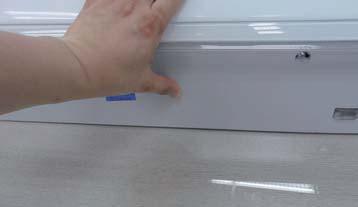
20 Center area Side area Side area HOOK F03,F04 F05 4-2


21 4-3
")


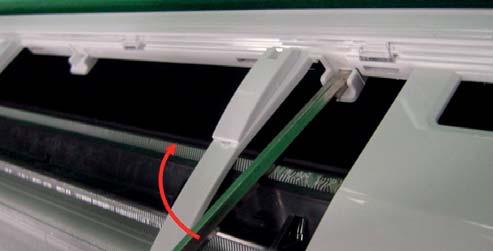
22 Hook (Side) Hook (Center) Screw Cap Screw 4-4


23 4-5


24


25 4-7


26


27 4-9


28


29 4-11


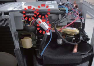
30 4-2 Outdoor Unit 3) Detach the Cabinet Upper lik e the picture. 4-12

 on the left (Use Screw")
 4-13")
31 5) Loosen 2 screw(ccw) on the right side of Cabinet Front. (Use Screw Driver) 6) Loosen 2 screw(ccw) on the left side of Cabinet Front. (Use Screw Driver) 7) Loosen 3 screw(ccw) on the front side of Cabinet Front. (Use Screw Driver) 4-13


32 8 4 9


33


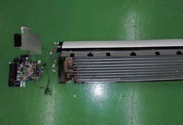
34 1) Release 2 screw at CAP FAN 2) Release Nut at Fan Boss 4) Detach Motor Wire from the Assy Control Out


35 5. ASSY CONTROL 5-1 ASSY KIT CODE DB B


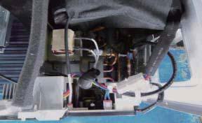
36 5-2 ASSY CONTROL OUT CODE QTY NAME SCREW-TAPPING 2 DB B 2 CABLE TIE 3 DB A 1 LABEL BAR CODE 4 DB A 1 ASSY COVER CONTROL-UP 5 DB F 1 ASSY CASE CONTROL KG GREASE-SILICON SCREW-TAPPING 8 DB A 1 HEAT SINK 9 DB A 1 ASSY CASE CONTROL 10 DB A 4 ASSY-SCREW MACHINE 11 DB A 1 ASSY MODULE 12 DB D 1 ASSY PCB MAIN 13 DB A 1 ASSY PCB SUB 14 DB F 1 ASSY CONNECTOR WIRE 15 DB E 1 ASSY CONNECTOR WIRE 16 DB A 1 ASSY PCB SUB-HEATER 17 DB A 1 ASSY CONNECTOR WIRE-POWER 18 DB A 1 ASSY CONNECTOR WIRE-DC SIGNAL 19 DB B 1 ASSY CONNECTOR WIRE-DC SIGNAL 20 DB A 1 ASSY CONNECTOR WIRE-DC SIGNAL 21 DB A 1 ASSY CONNECTOR WIRE 5-2


37 5-3 No Parts Procedure Remark 1 CASE Separate Case-WIFI Top from Case-WIFI Button 2 BUTTON Separate Case-WIFI Top from Case-WIFI Button 3 SCREW Detach SCREW from Case-WIFI Button Detach Assy Connector Wire from Case-WIFI Button 4 WIRE *Caution When you separate the connector, pull press -ing the locking button 5 PBA Separate PBA WIFI from Case-WIFI Button 5-3
38 6. Electrical Parts List 6-1 INDOOR MAIN PCB CODE DB A Parts Code Design Loc Parts Description Spec. Quantity Unit COATING ADHESIVE-SIL LDC2577D,Y/GRN,175CPS,- 2 G ADHESIVE-SIL ADHESIVE-SIL TSE3854DS-W,White,2.2,MIL-A-46146B,UL94V KG SOLDER-BAR SOLDER-BAR LeeD-free Solder BAR,W20L350H8,99.3Sn/0.7Cu/ G SOLDER-WIRE SOLDER-WIRE LFC2-W3.0,D3,99.79Sn/0.2Cu/0.01P,No Flux 1.51 G FLUX FLUX KSP-70M-S,MIXTURE,,FLUX,13% 0.14 G SOLVENT SOLVENT S-1000,(CH3)2CHOH,100%, G Q701 TR-POWER KSB1151-Y,PNP,1300mW,TO-126, PC VA71 VARISTOR 680V,560VDC,6000A,17x10mm,TP,1120V,350pF,D 1 PC XC71 C-FILM,LEAD-PPF 100nF,10%,275V,TP,12.5X6X PC XC72 C-FILM,LEAD-PPF 100nF,10%,275V,TP,12.5X6X PC BZ61 BUZZER-PIEZO 80dB,9V,2KHz,BK 1 PC CN76 HEADER-BOARD TO CABLE BOX,3P,1R,2.5MM,STRAIGHT,SN,WHT 1 PC CN21 HEADER-BOARD TO CABLE 1WALL,2P,1R,3.96MM,STRAIGHT,SN,RED 1 PC CN75 HEADER-BOARD TO CABLE 1WALL,2P,1R,7.92mm,STRAIGHT,SN,WHT,11.82x 1 PC CN72 HEADER-BOARD TO CABLE 1WALL,6P,1R,3.96MM,STRAIGHT,SN,WHT 1 PC CN81 HEADER-BOARD TO CABLE BOX,4P,1R,2.5mm,STRAIGHT,SN,YEL 1 PC CN77 CONNECTOR-HEADER BOX,5P,1R,2.5MM,STRAIGHT,SN,RED 1 PC CN61 HEADER-BOARD TO CABLE BOX,5P,1R,2.5mm,STRAIGHT,SN,WHT,5.8x14.9x7 1 PC CN31 HEADER-BOARD TO CABLE BOX,20P,2R,2.0mm,STRAIGHT,SN,BLK,5.0X22.0X6 1 PC CN71 HEADER-BOARD TO CABLE 1WALL,2P,1R,7.92mm,STRAIGHT,SN,BLU 1 PC CN91 HEADER-BOARD TO CABLE BOX,11P,1R,2mm,STRAIGHT,SN,WHT 1 PC CN32 HEADER-BOARD TO CABLE BOX,14P,1R,2mm,STRAIGHT,SN,WHT 1 PC CN43 HEADER-BOARD TO CABLE BOX,6P,1R,2mm,STRAIGHT,SN,WHT 1 PC CN42 HEADER-BOARD TO CABLE BOX,4P,1R,2mm,STRAIGHT,SN,WHT 1 PC CN63 HEADER-BOARD TO CABLE BOX,5P,1R,2MM,STRAIGHT,SN,BLK 1 PC CN62 HEADER-BOARD TO CABLE BOX,5P,1R,2MM,STRAIGHT,SN,BLU 1 PC DB A FT71 COIL CHOKE CV ,COIL CHOKE,28.0mH,+50~-30%, PC DB A FT81 COIL CHOKE 1.0mH,2.5A,8.4x3.4,Mn-Zn,4,DIP 1 PC DB A ASSY PCB AUTO MAIN,AR9500M,120*98,N,230V,19V, 12V, 5V,WIN 1 PC Q801 TR-SMALL SIGNAL KSC2328A-Y,NPN,1000mW,TO-92L,TP,160~320 1 PC PTC2 THERMISTOR-PTC 39ohm,20%,220/240V,270Vac,1.2A,TP 1 PC F701 FUSE-RADIAL LEAD 250V,3.15A,TIME-LAG,Thermoplastic,8.5x8mm 1 PC CN51 HEADER-BOARD TO CABLE BOX,5P,1R,2MM,STRAIGHT,SN,RED 1 PC DB A ASSY PCB SMD MAIN,AR9500M,120*98,N,230V,19V, 12V, 5V,WIN 1 PC SOLDER-CREAM SOLDER-CREAM LFM-48W TM-HP,D20~38um,96.5Sn/3Ag/0.5Cu,Fl 0.32 G D701 DIODE-RECTIFIER S1M,1000V,1A,SMA,TP 1 PC TD420 DIODE-TVS SM05,6V,20MAV,TP 1 PC TD501 DIODE-TVS SM05,6V,20MAV,TP 1 PC CD81 DIODE-TVS SMBJ5.0CA,6.4/-/7.25V,600W,SMB 1 PC CD82 DIODE-TVS SMBJ5.0CA,6.4/-/7.25V,600W,SMB 1 PC CD83 DIODE-TVS SMBJ5.0CA,6.4/-/7.25V,600W,SMB 1 PC Q501 TR-SMALL SIGNAL MMBT3904,NPN,350mW,SOT-23,TP,30~300 1 PC Q702 TR-SMALL SIGNAL MMBT3904,NPN,350mW,SOT-23,TP,30~300 1 PC Q601 TR-DIGITAL KRC246S,NPN,200mW,2.2K/10Kohm,SOT-23,TP 1 PC Q802 TR-DIGITAL KRC246S,NPN,200mW,2.2K/10Kohm,SOT-23,TP 1 PC IC05 TR-ARRAY 2003,NPN,7,1000mW,SOP-16,TP, PC IC06 TR-ARRAY 2003,NPN,7,1000mW,SOP-16,TP, PC PC03 PHOTO-COUPLER TR, %,170mW,SOP-4,TP 1 PC PC04 PHOTO-COUPLER TR, %,170mW,SOP-4,TP 1 PC PC05 PHOTO-COUPLER TR, %,170mW,SOP-4,TP 1 PC IC08 IC-CMOS LOGIC 74HC86,OR GATE,SOP,14P,150MIL,QUAD,ST,-,2.0 1 PC IC07 IC-BUS TRANSCEIVER SO,8P,4.9x3.8 mm,single,st,plastic,5v,-40to+ 1 PC IC11 IC-VOLTAGE COMP. 393,SOP,8P,150MIL,DUAL,36V,CMOS,PLASTIC,18V 1 PC IC03 IC-VOL. DETECTOR KIA7033AT,TSM,3P,2.9x1.6x0.7mm,PLASTIC,3.3V 1 PC IC02 IC-POSI.FIXED REG. 7815,TO-252,3Z30,6.6*6.1mm,14.4/15.6V,1.3W,- 1 PC R717 R-CHIP 0ohm,1%,1/10W,TP, PC R703 R-CHIP 1Kohm,1%,1/10W,TP, PC R706 R-CHIP 1Kohm,1%,1/10W,TP, PC R805 R-CHIP 1Kohm,1%,1/10W,TP, PC R815 R-CHIP 1Kohm,1%,1/10W,TP, PC R701 R-CHIP 10Kohm,1%,1/10W,TP, PC R704 R-CHIP 10Kohm,1%,1/10W,TP, PC R705 R-CHIP 10Kohm,1%,1/10W,TP, PC R723 R-CHIP 10Kohm,1%,1/10W,TP, PC R801 R-CHIP 10Kohm,1%,1/10W,TP, PC R802 R-CHIP 10Kohm,1%,1/10W,TP, PC R803 R-CHIP 10Kohm,1%,1/10W,TP, PC R804 R-CHIP 10Kohm,1%,1/10W,TP, PC R816 R-CHIP 10Kohm,1%,1/10W,TP, PC R825 R-CHIP 120ohm,5%,1/10W,TP, PC R511 R-CHIP 4.7Kohm,5%,1/16W,TP, PC R512 R-CHIP 4.7Kohm,5%,1/16W,TP, PC R513 R-CHIP 4.7Kohm,5%,1/16W,TP, PC R552 R-CHIP 4.7Kohm,5%,1/16W,TP, PC 6-1
39 Parts Code Design Loc Parts Description Spec. Quantity Unit R412 R-CHIP 10Kohm,5%,1/16W,TP, PC R413 R-CHIP 10Kohm,5%,1/16W,TP, PC R502 R-CHIP 10Kohm,5%,1/16W,TP, PC R503 R-CHIP 10Kohm,5%,1/16W,TP, PC R504 R-CHIP 10Kohm,5%,1/16W,TP, PC R505 R-CHIP 10Kohm,5%,1/16W,TP, PC R506 R-CHIP 10Kohm,5%,1/16W,TP, PC R521 R-CHIP 10Kohm,5%,1/16W,TP, PC R522 R-CHIP 10Kohm,5%,1/16W,TP, PC R523 R-CHIP 10Kohm,5%,1/16W,TP, PC R524 R-CHIP 10Kohm,5%,1/16W,TP, PC R525 R-CHIP 10Kohm,5%,1/16W,TP, PC R526 R-CHIP 10Kohm,5%,1/16W,TP, PC R527 R-CHIP 10Kohm,5%,1/16W,TP, PC R528 R-CHIP 10Kohm,5%,1/16W,TP, PC R529 R-CHIP 10Kohm,5%,1/16W,TP, PC R530 R-CHIP 10Kohm,5%,1/16W,TP, PC R531 R-CHIP 10Kohm,5%,1/16W,TP, PC R532 R-CHIP 10Kohm,5%,1/16W,TP, PC R533 R-CHIP 10Kohm,5%,1/16W,TP, PC R534 R-CHIP 10Kohm,5%,1/16W,TP, PC R543 R-CHIP 10Kohm,5%,1/16W,TP, PC R544 R-CHIP 10Kohm,5%,1/16W,TP, PC R551 R-CHIP 10Kohm,5%,1/16W,TP, PC R555 R-CHIP 10Kohm,5%,1/16W,TP, PC R556 R-CHIP 10Kohm,5%,1/16W,TP, PC R557 R-CHIP 10Kohm,5%,1/16W,TP, PC R807 R-CHIP 10Kohm,5%,1/16W,TP, PC R808 R-CHIP 10Kohm,5%,1/16W,TP, PC R810 R-CHIP 10Kohm,5%,1/16W,TP, PC R824 R-CHIP 10Kohm,5%,1/16W,TP, PC R826 R-CHIP 10Kohm,5%,1/16W,TP, PC R903 R-CHIP 10Kohm,5%,1/16W,TP, PC R904 R-CHIP 10Kohm,5%,1/16W,TP, PC R902 R-CHIP 47Kohm,5%,1/16W,TP, PC R820 R-CHIP 100Kohm,5%,1/16W,TP, PC R821 R-CHIP 100Kohm,5%,1/16W,TP, PC R831 R-CHIP 0ohm,5%,1/16W,TP, PC R833 R-CHIP 0ohm,5%,1/16W,TP, PC R835 R-CHIP 0ohm,5%,1/16W,TP, PC R837 R-CHIP 0ohm,5%,1/16W,TP, PC R839 R-CHIP 0ohm,5%,1/16W,TP, PC R843 R-CHIP 0ohm,5%,1/16W,TP, PC R702 R-CHIP 10Kohm,1%,1/4W,TP, PC R115 R-CHIP 14.3Kohm,1%,1/4W,TP, PC R712 R-CHIP 18Kohm,1%,1/10W,TP, PC R709 R-CHIP 1Mohm,1%,1/10W,TP, PC R714 R-CHIP 22Kohm,1%,1/10W,TP, PC R601 R-CHIP 330ohm,1%,1/10W,TP, PC R602 R-CHIP 330ohm,1%,1/10W,TP, PC R716 R-CHIP 330ohm,1%,1/10W,TP, PC R715 R-CHIP 39Kohm,1%,1/10W,TP, PC R707 R-CHIP 4.7Kohm,1%,1/10W,TP, PC R112 R-CHIP 470Kohm,1%,1/4W,TP, PC R113 R-CHIP 470Kohm,1%,1/4W,TP, PC R114 R-CHIP 470Kohm,1%,1/4W,TP, PC R711 R-CHIP 47Kohm,1%,1/10W,TP, PC R713 R-CHIP 5.6Kohm,1%,1/10W,TP, PC R708 R-CHIP 6.8Kohm,1%,1/10W,TP, PC R404 R-CHIP 330ohm,5%,1/16W,TP, PC R405 R-CHIP 330ohm,5%,1/16W,TP, PC R406 R-CHIP 330ohm,5%,1/16W,TP, PC R410 R-CHIP 330ohm,5%,1/16W,TP, PC R411 R-CHIP 330ohm,5%,1/16W,TP, PC R811 R-CHIP 330ohm,5%,1/16W,TP, PC R618 R-CHIP 12Kohm,1%,1/10W,TP, PC R508 R-CHIP 100ohm,1%,1/16W,TP, PC R515 R-CHIP 100ohm,1%,1/16W,TP, PC R516 R-CHIP 100ohm,1%,1/16W,TP, PC R517 R-CHIP 100ohm,1%,1/16W,TP, PC R518 R-CHIP 100ohm,1%,1/16W,TP, PC R519 R-CHIP 100ohm,1%,1/16W,TP, PC 6-2
40 Parts Code Design Loc Parts Description Spec. Quantity Unit R520 R-CHIP 100ohm,1%,1/16W,TP, PC R539 R-CHIP 100ohm,1%,1/16W,TP, PC R542 R-CHIP 100ohm,1%,1/16W,TP, PC R553 R-CHIP 100ohm,1%,1/16W,TP, PC R809 R-CHIP 100ohm,1%,1/16W,TP, PC R905 R-CHIP 100ohm,1%,1/16W,TP, PC R906 R-CHIP 100ohm,1%,1/16W,TP, PC R907 R-CHIP 100ohm,1%,1/16W,TP, PC R908 R-CHIP 100ohm,1%,1/16W,TP, PC R909 R-CHIP 100ohm,1%,1/16W,TP, PC R910 R-CHIP 100ohm,1%,1/16W,TP, PC R401 R-CHIP 6.8Kohm,1%,1/16W,TP, PC R402 R-CHIP 6.8Kohm,1%,1/16W,TP, PC R403 R-CHIP 6.8Kohm,1%,1/16W,TP, PC R538 R-CHIP 1Kohm,1%,1/16W,TP, PC R545 R-CHIP 1Kohm,1%,1/16W,TP, PC R806 R-CHIP 1Kohm,1%,1/16W,TP, PC R901 R-CHIP 1Kohm,1%,1/16W,TP, PC R301 R-CHIP 300Kohm,1%,1/4W,TP,3216,T PC R302 R-CHIP 300Kohm,1%,1/4W,TP,3216,T PC R303 R-CHIP 300Kohm,1%,1/4W,TP,3216,T PC C705 C-CER,CHIP 10nF,10%,50V,X7R,TP, PC C801 C-CER,CHIP 10nF,10%,50V,X7R,TP, PC C508 C-CER,CHIP 1nF,10%,50V,X7R,TP, PC C516 C-CER,CHIP 1nF,10%,50V,X7R,TP, PC C520 C-CER,CHIP 1nF,10%,50V,X7R,TP, PC C901 C-CER,CHIP 1nF,10%,50V,X7R,TP, PC C715 C-CER,CHIP 1nF,10%,50V,X7R,TP, PC C519 C-CER,CHIP 0.056nF,5%,50V,C0G,TP, PC C711 C-CER,CHIP 0.005nF,0.1pF,50V,NP0,TP, PC C501 C-CER,CHIP 100nF,10%,50V,X7R,TP, PC C513 C-CER,CHIP 100nF,10%,50V,X7R,TP, PC C514 C-CER,CHIP 100nF,10%,50V,X7R,TP, PC C702 C-CER,CHIP 100nF,10%,50V,X7R,TP, PC C704 C-CER,CHIP 100nF,10%,50V,X7R,TP, PC C710 C-CER,CHIP 100nF,10%,50V,X7R,TP, PC C712 C-CER,CHIP 100nF,10%,50V,X7R,TP, PC C713 C-CER,CHIP 100nF,10%,50V,X7R,TP, PC C802 C-CER,CHIP 100nF,10%,50V,X7R,TP, PC C803 C-CER,CHIP 100nF,10%,50V,X7R,TP, PC C805 C-CER,CHIP 100nF,10%,50V,X7R,TP, PC C806 C-CER,CHIP 100nF,10%,50V,X7R,TP, PC C807 C-CER,CHIP 100nF,10%,50V,X7R,TP, PC C401 C-CER,CHIP 100nF,10%,16V,X7R,TP,1005,T0.5 1 PC C402 C-CER,CHIP 100nF,10%,16V,X7R,TP,1005,T0.5 1 PC C403 C-CER,CHIP 100nF,10%,16V,X7R,TP,1005,T0.5 1 PC C410 C-CER,CHIP 100nF,10%,16V,X7R,TP,1005,T0.5 1 PC C411 C-CER,CHIP 100nF,10%,16V,X7R,TP,1005,T0.5 1 PC C412 C-CER,CHIP 100nF,10%,16V,X7R,TP,1005,T0.5 1 PC C517 C-CER,CHIP 100nF,10%,16V,X7R,TP,1005,T0.5 1 PC C521 C-CER,CHIP 100nF,10%,16V,X7R,TP,1005,T0.5 1 PC C522 C-CER,CHIP 100nF,10%,16V,X7R,TP,1005,T0.5 1 PC C529 C-CER,CHIP 100nF,10%,16V,X7R,TP,1005,T0.5 1 PC C530 C-CER,CHIP 100nF,10%,16V,X7R,TP,1005,T0.5 1 PC C531 C-CER,CHIP 100nF,10%,16V,X7R,TP,1005,T0.5 1 PC C533 C-CER,CHIP 100nF,10%,16V,X7R,TP,1005,T0.5 1 PC C809 C-CER,CHIP 100nF,10%,16V,X7R,TP,1005,T0.5 1 PC C707 C-CER,CHIP 2.2nF,10%,50V,X7R, PC C708 C-CER,CHIP 1000nF,10%,50V,X7R,TP, PC C509 C-CER,CHIP 1000nF,10%,25V,X5R,TP,1005(1106),T0.5 1 PC C512 C-CER,CHIP 1000nF,10%,25V,X5R,TP,1005(1106),T0.5 1 PC C515 C-CER,CHIP 1000nF,10%,25V,X5R,TP,1005(1106),T0.5 1 PC C518 C-CER,CHIP 1000nF,10%,25V,X5R,TP,1005(1106),T0.5 1 PC C523 C-CER,CHIP 1000nF,10%,25V,X5R,TP,1005(1106),T0.5 1 PC C526 C-CER,CHIP 1000nF,10%,25V,X5R,TP,1005(1106),T0.5 1 PC C528 C-CER,CHIP 1000nF,10%,25V,X5R,TP,1005(1106),T0.5 1 PC C551 C-CER,CHIP 1000nF,10%,25V,X5R,TP,1005(1106),T0.5 1 PC C552 C-CER,CHIP 1000nF,10%,25V,X5R,TP,1005(1106),T0.5 1 PC C808 C-CER,CHIP 1000nF,10%,25V,X5R,TP,1005(1106),T0.5 1 PC C804 C-CER,CHIP 1000nF,10%,50V,X5R,TP, PC C706 C-AL,SMD 10UF,20%,50V,GP,TP,6.6X6.6X5.4MM 1 PC C701 C-AL,SMD 47uF,20%,50V,GP,TP,6.3X7.7mm 1 PC C703 C-AL,SMD 47uF,20%,50V,GP,TP,6.3X7.7mm 1 PC X501 RESONATOR-CERAMIC 8MHz,0.5%,TP,3.2x1.3x0.9 mm 1 PC DB A PCB MAIN PCB MAIN FR-4,2Layer,T1.6,120*98,4,WIND FREE, A-STD#4 1 PC DB A IC04 ASSY MICOM 17K_RAC_A3050_Inverter,STM-1632-OA,HART-m3 1 PC IC-MICROCONTROLLER HART-M310,QFP,100P,20x14mm,8MHz,5V,600mW 1 PC 6-
41 6-2 OUTDOOR MAIN PBA(DB D) 6-4
42 OUTDOOR MAIN PBA(DB D) 6-5
43 OUTDOOR MAIN PBA(DB D) 6-6
44 OUTDOOR MAIN PBA(DB D) 6-7
45 OUTDOOR MAIN PBA(DB D) 6-8
46 OUTDOOR MAIN PBA(DB D) 6-9
47 6-3 DB A Parts Code Design Loc Parts Description Spec. Q Ty DB A 001 ASSY PCB DISPLAY BETTER,BEST,A3050,64* ADHESIVE-SIL ADHESIVE-SIL LDC2577D,Y/GRN,175CPS, SOLDER-BAR SOLDER-BAR LeeD-free Solder BAR,W20L350H8,99.3Sn/0.7Cu/0.01P SOLDER-WIRE SOLDER-WIRE LFC2-W3.0,D3,99.79Sn/0.2Cu/0.01P SOLDER-WIRE FLUX SOLDER-WIRE FLUX LFC7-107,D0.8,99.3Sn/0.7Cu/0.01P,Flux3-4% FLUX FLUX KSP-70M-S,MIXTURE,,FLUX,13% SOLVENT SOLVENT S-1000,(CH3)2CHOH,100%, CN01 HEADER-BOARD TO CABLE BOX,11P,1R,2mm,STRAIGHT,SN,WHT CN03 HEADER-BOARD TO CABLE BOX,2P,1R,2mm,STRAIGHT,SN,WHT,5.98x5.1x7.7mm CN02 HEADER-BOARD TO CABLE BOX,4P,1R,2mm,STRAIGHT,SN,WHT CN05 HEADER-BOARD TO CABLE BOX,4P,1R,2mm,STRAIGHT,SN,WHT CN04 HEADER-BOARD TO CABLE BOX,5P,1R,2MM,STRAIGHT,SN,BLK 1 DB A IC02 LED DISPLAY WHITE,TRAY,390x360,29.0x23.0x DB A ASSY PCB AUTO ASSY PCB AUTO INDOOR,A3050,64*36,N,DISPLAY BETTER,BEST,DB A LED1 LED ROUND,WHT,3.1mm,3.9x5.4mm LED2 LED ROUND,WHT,3.1mm,3.9x5.4mm
48 (OPTION) YEL BLK 1 SPI (OPTION) HUMIDITY SENSOR (OPTION) ROOM-TH 10K INDOOR MID PIPE-TH 10K INDOOR IN PIPE-TH 10K THERMISTOR OPTION PBA (OPTION) FP01 T2A 250V SMPS MODULE (OPTION) CONVERTER & WiFi MODULE (OPTION) CONVERTER & WiFi MODULE BLK CN81 (YEL) CN42 (WHT) CN43 (WHT) RED FJM/ 5 5 NASA CN (WHT) (OPTION) 14 CON01 (WHT) 1 BRN CN75 (WHT) CON03 CN77 (RED) (RED) RED CN76 CON02 (WHT) (WHT) RED CN71 (BLU) THERMAL FUSE RED RED EMI FILTER RED CN (RED) (OPTION1) 1 RED CN51 (RED) (OPTION2) 5 GRN 4 YEL 3 ORG 2 RED 1 (OPTION) EMI FILTER F701 T3.15A 250V 3 2 BRN 1 SKY CN65 (BLK) CN64 (WHT) CN61 (WHT) CN62 (BLU) CN63 (BLK) CN72 (WHT) CN91 (WHT) CN21 (RED) RED 1(L) 2(N) F1 F2 1 2 BLU UP/DOWN STEP MOTOR 1 EA : OPTION 1 2 EA : OPTION 2 GRILLE STEP MOTOR (OPTION) UP/DOWN STEP MOTOR (OPTION) RED UP/DOWN STEP MOTOR (OPTION1) (OPTION) WHT RED TE - THERMISTER MARK BASED ON THE TEMP 25 C RED BLK YEL (OPTION) 6 RED ISE ABSORBER CN01 (WHT) (OPTION) (OPTION) 1(L) 2(N) F1 F2 L1 L2 F1 F2 L3 L4 F1 F2 RED LEFT/RIGHT STEP MOTOR CN02 (WHT) CN05 CN03 (WHT) (WHT) DISPLAY (OPTION) ORG UP/DOWN STEP MOTOR1 UP/DOWN STEP MOTOR2 (OPTION2) GRILLE STEP MOTOR1 GRILLE STEP MOTOR2 (OPTION) RECEIVER ORG 1 1 RECEIVER (OPTION) RED 1 SPI 2 LIGHTING (OPTION) TEST CONNECTOR GRN/YEL GRN/YEL EARTH CN04 (BLK) WHT (OPTION) M BLDC CN01 (WHT) CN01 (WHT) TERMINAL BLOCK 1(L)/L1/L3. POWER (L) 2(N)/L2/L4. POWER (N) F1. COMMUNICATION F2. COMMUNICATION <-> E203 E422/E554 E458 E461 E464 E465 E500 Time out comm. (Inv Micom <-> Main Micom) EEV or Valve Close error-self diagnosis /Gas Leak Error Out door and Fan Error Comp. Starting Error IPM Over Current (O.C) Error Comp V_Iimit/I_limit Error Heatsink overheat or IPM overheat CODE : DB A INDOOR - UNIT 7-1
49 7-2 Outdoor Unit 7-2

50 Indoor Main PCB : DB A CN150 CN802 CN800 CN100 CN810 CN801 CN330 CN50 CN400 CN820 CN320 CN420 CN300 CN700 CN340 CN340 : FJM BLOCK CN500 : DISPLAY CN700 : BLDC FAN #1 : COM2_RXD #1 : DIO #1 : 310V #2 : COM2_TXD #2 : CLK #2 : NULL #3 : COM2_ENABLE #3 : STB #3 : PGND #4 : COM2_LED #4 : IRQ #4 : 15V #5 : EXT_CTRL #5 : GND #5 : BLDC_MOTOR #6 : COMP_CHK #6 : 5VCC #6 : MOTOR_FB #7 : ERROR_CHK #7 : Vout #8 : 5VCC #8 : PWM_LED CN800 : STEP-UP/DOWN #9 : GND #9 : TEST_RX #1 : 12V #10 : 12V #10 : NULL #2 : O5 #11 : NULL #3 : O4 CN150 : THERMAL FUSE BLOCK #4 : O3 #1 : THERMAL_FUSE CN320 : 485 COMMUNICATION #5 : O2 #2 : SGND #1 : RXD1 #2 : TXD1 CN801 : STEP MOTOR-L/R CN300 : DOWNLOAD #1 : 12V #1 : RXD1 CN330 : WiFi BLOCK #2 : O5 #2 : TXD1 #1 : MAIN_RX-WiFi_TX #3 : O6 #3 : BOOT #2 : MAIN_TX-WiFi_RX #4 : O7 #4 : J-TAG_TDO #3 : WiFi_RESET #5 : O1 #5 : J-TAG_TCK #4 : GND #6 : J-TAG_TDI #5 : 12V CN810 : SPI BLOCK #7 : J-TAG_TMS #1 : SPI #8 : TraceCLK CN100 : SPMS #2 : NULL #9 : GND #1 : L #3 : 12V #10 : VCC #2 : NULL #4 : NULL #11 : NULL #3 : N #12 : NULL CN400 : SENSOR BLOCK #13 : NULL CN820 : FILTER BLOCK #1 : ROOM_TEMP #14 : Trace3 #1 : SGND #2 : GND #15 : NULL #2 : L_K1_MODE #3 : EVA_TEMP #16 : NULL #3 : L_K1_PS #4 : GND #17 : GND #4 : K1_FB #5 : EVA2_TEMP #18 : Trace2 #5 : 12V #6 : GND #19 : Trace1 #20 : Trace0 CN420 : HUM/TEMP BLOCK CN802 : STEP MOTOR-2 #1 : 5V_VCC #1 : 12V #2 : GND #2 : O1 #3 : H_ROOM_TEMP #3 : O2 #4 : HUM_SENSOR #4 : O3 #5 : O4 8-1

51 8-2 Outdoor PCB ;AR18KSFPDWQXCV CN206 Heater Drive signal #1:Heater 1 Signal #2:Heater 2 Signal CN205 DC Power #1:12V #2:GND CN151 - SMPS INV #1 : 15V #2 : GND #3 : ENABLE CN204 - DRED #1 : DRED1 #2 : DRED2 #3 : DRED3 #4 : GND #5 : 5V CN201- DOWNLOAD-MAIN #1 ~ #20 : DOWNLAOD CN251 - SENSOR #1,#2 : OUT SENSOR #3,#4 : DISCHARGE SENSOR #5,#6 : COND SENSOR CN501 - EEPROM #1 : GND #3 : 5V #4 : EEP CS #5 : EEP_SO/MICOM RX #6 : EEP_SI_MICOM_TX #7 : EEP CLK CN701 - EEV-A #1~#4 : EEV SIGNAL #5 : 12V CN152 - SMPS MAIN #1 : 12V #2 : GND #3 : 5V CN301 - COMMUNICATION #1 : F1 #2 : F2 CN901 - FAN #1 : DC 310~340V #2 : N.C #3 : AGND #4 : DC 15V #5 : FAN RPM #6 : FAN FEEDBACK CN401- REACTOR #1 : REACTOR1 #2 : REACTOR2 CN030-4WAY #1,#3 : AC220~240V CN001 - POWER-N #1 : N CN002 - POWER-L #1 : L CN003 - EARTH #1 : EARTH CN150 - SMPS AC #1,#3 : AC220~240V CN402 - COMP #1 : W #2 : V #3 : U 8-2

52 Display PCB : DB A CN01 CN04 CN02 CN01 CN02 CN04 #1 DIN/DOUT #1 GND #1 DIN/DOUT #2 CLK #2 Vout #2 CLK #3 STB #3 5VDC #3 STB #4 IRQ #4 IRQ #4 SWITCH INPUT #5 GND #5 GND #6 5VDC #7 Vout #8 PWM_LED #9 TEST_RX #10 TEST_TX #11 MODE0 8-3

53 8-4 SUB PCB--RECEIVE-DB A CN01 CN61/CN62/CN63 - RECEIVE - #1 : GND #2 : Vout #3 : Vcc #4 : S/W CN71 - POWER IN CN32 - FJM/NASA CN76 - SMPS DC OUT SMPS DC OUT 8-4


54 8-5 Wire connecting the indoor unit terminal blocks 1. Terminal press of Ring terminal shall be set facing up before connecting wire. Is inverted Terminalhasbeencut. 2. There shall be no empty space between Ring terminal and Screw after Clamp. If not, there exists a possibility ich can be caused by electric heat in the connecting part., : Good Bad : Ring terminal is connected reversely Bad : Not clamped Screw Bad : In the gap between Ring terminal & Screw Bad : Unused Ring Terminal 8-5
55 9. Operating Instructions 9-1 Name of Each Part Indoor Unit The design and shape are subject to change according to the model. Main Parts The actual product may differ slightly from the image depicted below. W\ WX W] WY W^ W_ WZ W` W[ XW Air intake Air ѣlter Air Ѥow blade (up and down) Air Ѥow blade (left and right) Room temperature sensor WI-FI module Wind-free panel Display Power button /Remote control receiver (Inside) Virus doctor Display 01 Temperature indicator Filter reset indicator ( ) Electricity consumption indicator Auto clean indicator ( ) Defrost indicator ( ) 02 Wi-Fi indicator 03 Single user indicator 04 Timer indicator good'sleep indicator Auto clean indicator WX WY WZ W[
56 9-2 Wireless Remote control-buttons and Display 01 Set temperature indicator 02 Timer option indicator 03 Operation mode indicator 04 Options indicator 05 Low battery indicator 06 Transmit indicator 07 Fan speed indicator 08 Virus doctor indicator 09 Wind-free indicator 10 Vertical air swing indicator 11 Horizontal air swing indicator 12 Power button 13 Temperature button 14 Timer button 15 Fan speed button 16 Direction button / Selection button 17 Vertical air swing button 18 Mode button 19 Single user/ Wind-free button 20 Horizontal air swing button 21 Options / Clean button 22 SET button
57 10. Troubleshooting 10-1 Items to be checked first 1. The input voltage should be rating voltage 10% range. The air conditioner may not operate properly if the voltage is out of this range. 2. Is the line cable linking the indoor unit and the outdoor unit linked properly? The indoor unit and the outdoor unit shall be linked by 5 cables. Check the terminals if the indoor unit and outdoor unit are properly linked by the same number of cables. Otherwise the air conditioner may not operate properly. 3. When a problem occurs due to the contents illustrated in the table below it is a symptom not related to the malfunction of the air conditioner. Operation of air conditioner Explanation 1 2 The OPERATION indication LED(BLUE) blinks when a power plug of the indoor unit is plugged in for first time. In a COOL operation mode, the compressor does not operate at a room temperature higher than the setting temperature that the INDOOR FAN should operate. [ In case of heat pump model ] In a HEAT operation mode, the compressor does not operate at a room temperature lower than the setting temperature that indoor fan should operate. It indicates power is on. The LED stops blinking if the operation ON/OFF button on the remote control unit is pushed. In happens after a delay of 3 minutes when the compressor is reoperated. The same phenomenon occurs when a power is on. As a phenomenon that the compressor is reoperated after a delay of 3 minutes, the indoor fan is adjusted automatically with reference to a temperature of the air blew. 3 Fan speed setting is not allowed in DRY mode. The speed of the indoor fan is set to LL in DRY mode. Fan speed is selected automatically in AUTO mode Compressor stops operation intermittently in Dry mode. Timer LED(ORANGE) of the indoor unit lights up and the air conditioner does not operate. The compressor stops intermittently in a COOL mode or DRY mode, and fan speed of the indoor unit decreases. [In case of heat pump model] Compressor of the outdoor unit is operating although it is turned off in a HEAT mode. [In case of heat pump model] The compressor and indoor fan stop intermittenly in HEAT mode. [In case of heat pump model] Indoor fan and outdoor fan stop operation intermittently in a HEAT mode. Compressor operation is controlled automatically in DRY mode depending on the room temperature and humidity. Timer is being activated and the unit is in ready mode. The unit operates normally if the timer operation is cancelled. The compressor stops intermittently or the fan speed of the indoor unit decreases to prevent inside/outside air frozen depending on the inside/outside air temperature. When the unit is turned off while de-ice is activated, the compressor continus operation for up to 9 minutes(maximum) until the deice is completed. The compressor and indoor fan stop intermittently if room temperature exceeds a setting temperature in order to protect the compressor from overheated air in a HEAT mode. The compressor operates in a reverse cycle to remove exterior ice in a HEAT mode, and indoor fan and outdoor fan do not operate intermittently for within 20% of the total heater operation. 10-1
58 10-2 Communication Error Communication Error Indoor display 3-LED DISPLAY 7-SEG DISPLAY DESCRIPTION LED1 LED2 LED3 E101/E102 Communication error(indoor<->outdoor) Outdoor display 1min. Time out Comm. Abnormal Communication LED ON LED BLINKING LED OFF 1. Checklist : 1) Is the cable between the indoor unit and outdoor unit connected correctly? 2) Isn't the power cable and communication cable cross? 2. Troubleshooting procedure Restart after power o. Is the communication error occurred again? Terminate the service. Is the connection of power cable and communication cable normal? Correct the wrong cable. Is the power is normal? (check the LED Lamp) Exchange the PBA of no power unit Exchange the indoor unit PBA. Is the communication error occurred again? Terminate the service. Exchange the outdoor unit PBA. 10-2
59 Indoor temperature sensor Error Indoor display 3-LED DISPLAY 7-SEG DISPLAY DESCRIPTION LED1 LED2 LED3 E121 Indoor room temp sensor error LED ON LED BLINKING LED OFF 1. Checklist : 1) Is the indoor units temperature sensor connected correctly? 2) Is the sensor placed correctly? 3) Does the both terminal of sensor satisfy the resistance value in accordance with temperature? 2. Troubleshooting procedure Detach the assembled sensor from the PBA sensor connector and measure the sensor resistance with ohmmeter(tester) Is the sensor resistance value 10kohm±3% at the room temperature of 25 C Connect the sensor to PBA connector (6piin) supply power Is the connection and measure of the power voltage cable of #1-#2 in and communication the connector cable normal? Ass'y Sensor Replace Sensor resistance value : 20 C kohm 30 C kohm 35 C kohm 40 C- 5.83kohm Below 0.5V or Over 4.5V? Exchange the indoor PBA Micom error or connector check Exchange the indoor PBA 10-3
60 Indoor fan motor speed detecting error (BLDC fan) Indoor display 3-LED DISPLAY 7-SEG DISPLAY DESCRIPTION LED1 LED2 LED3 E154 Indoor fan error LED ON LED BLINKING LED OFF 1. Checklist : 1) Is the indoor units fan motor properly connected with the connector(cn72)? 2) Is the AC voltage correct? 2. Troubleshooting procedure Restart after power o Does the fan rotate? Power o ate the Fan motor wire from CN72 on Indoor PBA Reassemble the fan wire and input the power again Is there short among each pin #1~#6 Exchange the Fan motor Is the fan error appeared again? Terminate the service Is the voltage of CN72 #1-#3 over 250Vdc Follow the check procedure of Indoor unit power supply error check Is the voltage of CN72 #3-#5 and #3-#6 with in 1Vdc~15Vdc during the operation? Exchange the Indoor PBA PBA problem or Motor problem Change the PBA first and check the operation Exchange the Fan motor 10-4
 Is the sensor connected correctly? 2) Is the sensor placed correctly?")
61 Outdoor temperature sensor error Indoor display 3-LED DISPLAY 7-SEG DISPLAY DESCRIPTION LED1 LED2 LED3 E221 Outdoor temperature sensor error Outdoor display LED ON LED BLINKING LED OFF Outdoor temperature sensor error 1. Checklist : 1) Is the sensor connected correctly? 2) Is the sensor placed correctly? 3) Does the both terminal of sensor satisfy the resistance value in accordance with temperature? 4) Is the resistance value of sensor connection pull-up correct? 2. Troubleshooting procedure MODEL "A" "B" ALL CN251 CN251 #1-#2 Is the sensor connector("a") connected correctly in accordance with a color? Reconnect the sensor connector. Is the sensor resistance value "B" 10kohm±3% at the room temperature of 25 Connect the sensor to PBA connector supply Is the power connection and measure of power the cable voltage of and communication "B"in the connector cable normal? Sensor Replace Sensor resistance value : kohm kohm kohm kkohm Below 0.5Vdc or Over 4.5Vdc? Exchange the Outdoor PBA Micom error or connector check Exchange the Outdoor PBA 10-5
62 Outdoor Cond temperature sensor error Indoor display 3-LED DISPLAY 7-SEG DISPLAY DESCRIPTION LED1 LED2 LED3 E231 Outdoor Cond temperature sensor error Outdoor display LED ON LED BLINKING LED OFF Outdoor Cond temperature sensor error 1. Checklist : 1) Is the sensor connected correctly? 2) Is the sensor placed correctly? 3) Does the both terminal of sensor satisfy the resistance value in accordance with temperature? 4) Is the resistance value of sensor connection pull-up correct? 2. Troubleshooting procedure MODEL "A" "B" ALL CN251 CN251 #5-#6 Is the sensor connector("a") connected correctly in accordance with a color? Reconnect the sensor connector. Is the sensor resistance value "B" 10kohm±3% at the room temperature of 25 Connect the sensor to PBA connector supply power Is the and connection measureof the power voltage cableof "B" and communication in the connector cable normal? Sensor Replace Sensor resistance value kohm kohm kohm kohm Below 0.5Vdc or Over 4.5Vdc? Exchange the Outdoor PBA Micom error or connector check Exchange the Outdoor PBA 10-6
 Is the sensor connected correctly? 2) Is the sensor placed correctly?")
63 Outdoor Discharge temperature sensor error Indoor display 3-LED DISPLAY 7-SEG DISPLAY DESCRIPTION LED1 LED2 LED3 Outdoor Discharge temperature E251 sensor error Outdoor display Outdoor Discharge temperature sensor error LED ON LED BLINKING LED OFF 1. Checklist : 1) Is the sensor connected correctly? 2) Is the sensor placed correctly? 3) Does the both terminal of sensor satisfy the resistance value in accordance with temperature? 4) Is the resistance value of sensor connection pull-up correct? 2. Troubleshooting procedure MODEL "A" "B" ALL CN251 CN251 #3-#4 Is the sensor connector("a") connected correctly in accordance with a color? Reconnect the sensor connector. Is the sensor resistance value "B" 200kohm±3% at the room temperature of 25 Connect the sensor to PBA connector supply power Is the and connection measureof the power voltage cableof "B"in the andconnector communication cable normal? Sensor Replace Sensor resistance value kohm ohm ohm kohm Below 0.5Vdc or Over 4.5Vdc? Exchange the Outdoor PBA Micom error or connector check Exchange the Outdoor PBA 10-7
64 Operation condition secession error Indoor display 3-LED DISPLAY LED1 LED2 LED3 Outdoor display LED ON LED BLINKING LED OFF 7-SEG DISPLAY E440 E441 DESCRIPTION Prohibit Operation Condition Error (Heating) Prohibit Operation Condition Error (Cooling) Operation condition secession 1. Checklist : 1) Check the temperature around the outdoor unit. 2. Troubleshooting procedure Restart after power o Is the operation condition secession error appeared again? Terminate the service * Heating mode * Is the outdoor temperature over 40 or under -30? * Cooling mode * Is the outdoor temperature under -7 The temperature condition is too poor to operate. Wait until temperature is changed 10-8
65 EEPROM error / OTP error Indoor display 3-LED DISPLAY LED1 LED2 LED3 Outdoor display LED ON LED BLINKING LED OFF 7-SEG DISPLAY E470 E471 DESCRIPTION EEPROM Data Error (no data) OTP erroreeprom Data Error (Main Micom Inv Micom) EEPROM Data Error (no data) OTP erroreeprom Data Error (Main MicomInv Micom) 1. Checklist : 1) Is there a short around micom? 2) Is there a short around "A"? 3) Did you download or insert EEPROM IC, after changing outdoor PBA? 2. Troubleshooting procedure EEPROM data (or. Insert the service EEPROM IC) MODEL DB A DB A CN501 CN202 "A" Restart after power o Is the error appeared again? Terminate the service Exchange the Outdoor PBA 10-9
66 Outdoor Fan motor error Indoor display 3-LED DISPLAY 7-SEG DISPLAY DESCRIPTION LED1 LED2 LED3 E458 Outdoor fan error Outdoor display LED ON LED BLINKING LED OFF Outdoor fan error 1. Checklist : 1) Are the input power voltage and the power connection correct? 2) Is the motor wire connected to the outdoor PBA correctly? 3) Is there no assembly error or non-assembly in the terminal of motor wire connector? 4) Is there no obstacle at the surrounding of motor and propeller? 2. Troubleshooting procedure Restart after power. MODEL ALL "A" CN901 Does the fan rotate? Power and Separate the Fan motor wire from "A" on Outdoor PBA Reassemble the fan wire and input the power again Is there short among each pin #1~#6 Exchange the Fan motor Is the fan error appeared again? Terminate the service Is the voltage of "A" #1-#3 over 250Vdc Follow the check procedure of outdoor unit powersupplyerrorcheck Is the voltage of "A" #3-#5 and #3-#6 with in 1Vdc~15Vdc during the operation? Exchange the Outdoor PBA PBA problem or Motor problem Change the rst and check the operation Exchange the Fan motor 10-10
67 Compressor starting error Indoor display 3-LED DISPLAY 7-SEG DISPLAY DESCRIPTION LED1 LED2 LED3 E461 Comp starting error Outdoor display LED ON LED BLINKING LED OFF Comp starting error 1. Checklist : 1) Is the connection of cable for the compressor? 2) Is the compressor wire is connected clockwise? U(RED)-V(BLU)-W(YEL) 3) Is the interphase resistance of compressor normal? 2. Troubleshooting procedure Restart after power. Is the restart error occurred again? Terminate the service Is the connection of compressor wire is normal? Connect the comp wire normally Download the EEPROM data Is the restart error occurred again? Terminate the service Is the compressor body and interphase resistance insulated? Exchange the Outdoor PBA Exchange the compressor 10-11
68 Compressor wire missing error/rotation error Indoor display 3-LED DISPLAY 7-SEG DISPLAY DESCRIPTION LED1 LED2 LED3 Compressor wire missing E467 errorr/rotation error Outdoor display LED ON LED BLINKING LED OFF 1. Checklist : 1) Is the connection of cable for the compressor? 2) Is the compressor wire is connected clockwise? U(RED)-V(BLU)-W(YEL) 3) Is the interphase resistance of compressor normal? Compressor wire missing error/rotation error 2. Troubleshooting procedure Restart after power off. Is the restart error occurred again? Terminate the service Is the connection of compressor wire is normal? (PBA and Compressor) Connect the comp wire normally Is the restart error occurred again? Terminate the service Is the compressor body and interphase resistance insulated? Exchange the Outdoor PBA Exchange the compressor 10-12
69 Current sensor error/input current sensor error Indoor display 3-LED DISPLAY LED1 LED2 LED3 Outdoor display LED ON LED BLINKING LED OFF 7-SEG DISPLAY E462 DESCRIPTION Current sensor error Input current sensor error AC Input I_Limit Trip Error 1. Checklist : 1) Is the PFC Shunt("A") resistance value correct? Check the resistor is opened 2) Is the IPM Shunt("B") resistance value correct? Check the resistor is opened 3) Is there no short or open around "C"? 2. Troubleshooting procedure Restart after power. MODEL "A" "B" "C" DB A R426,R425 R410,R411,R412 IC451 DB A R063,R064,R065 R408,R409,R410 IC451 Is the PFC shunt and IPM shunt resistance value correct? Exchange the Outdoor PBA Is the current sensor error appeared again? Terminate the service Exchange the Outdoor PBA 10-13
70 O.C(Over Current) error Indoor display 3-LED DISPLAY 7-SEG DISPLAY DESCRIPTION LED1 LED2 LED3 E464 IPM Over Current(O.C) Error Outdoor display LED ON LED BLINKING LED OFF IPM Over Current(O.C) Error 1. Checklist : 1) Is the IPM Shunt resistance value correct? Check the resistor is opened 2) Is the condition of surrounding temperature abnormal overload? 3) Is there any problem as like the temperature sensor separation or measurement value error? 4) Is the interphase resistance of compressor normal? 2. Troubleshooting procedure Restart after power off. Is the O.C error occurred? Terminate the service Is the connection of compressor wire is normal? Connect the comp wire normally Is the O.C error occurred again? Terminate the service Is the condition of indoor/outdoor temperature normal load? Restart after returning to the normal load Is the O.C error occurred again? Terminate the service 10-14
71 Is the position of temperature sensor and sensing value normal? Correct the sensor position or exchange the sensor Is the compressor body and interphase resistance insulated? Exchange the Outdoor PBA Exchange the compressor 10-15
72 No power outdoor (Initial Diagnosis) (Not displayed) 1. Checklist : 1) Is input power normal? 2) Is AC power linked correctly? (L,N,E) 3) Is mis-wiring between communication wire and Power wire? 4) Is mis-wiring between Main PBA and SMPS PBA wire? 5) Is input voltage of SMPS AC in Main PBA (CN150) normal? 6) Is the voltage of SMPS DC in Main PBA (CN151,CN152) normal? 2. Troubleshooting procedure Unplug the power cord MODEL ALL Is thepowercablefrom terminal block to PBA is correct?l :CN002, N:CN001, EARTH:CN003 Reconnect the power wire correctly. Check the fuse open or not? (F001) Exchange the Main PBA Rest Is the power normal? Check the power source. Is AC power is normal for SMPS? CN150 : 220Vac~240Vac Exchange the Main PBA Check SMPS wire connection 10-16
73 When the Up/Down, Left/Right, Grill louver motor does not operate (Initial Diagnosis) (Not displayed) 1. Checklist : 1) Is the input power voltage normal? 2) Is the Up/Down louver motor properly connected with the connector? (CN61, CN62, CN63) 2. Troubleshooting procedure Unplug the power cord and plug it after 30seconds later. Is the lamp blinking? Check the as in the procedure. No power. Is the connected louver wire? Connect the wire PBA to louver motor Does operation start when swing button of the remote control unit pushed? Normal Is the voltage changeable at the pin#2~#5 of CN61, CN62, CN63 (louver connector)? Exchange the PBA Up/Down louver motor is faulty
74 When the remote control is not receiving 1. Checklist : 1) Check if the connector was normally assembled. 2) Check the battery in remote control 3) All the lights out and check again : Change electronic typed to a rescent light 4) Put the set in operation and check the voltage of display PBA 5) Replace the display PBA 2. Troubleshooting procedure If the connector was normally assemble? Check the connector to normally assemble. Have the battery in remote control? Insert the battery in remote control. All the lights out? Re-check the connector Exchange the display PBA 10-18
75 Smart Install error 1. Checklist : 1) Check the leakage region.(use leakage detection liquid or soapy water) 2) When leakage region is found from service valve and piping connection re nut part : After the related measures to check the refrigerant supplements and operation. 3) If the leakage region is pipe welding part : Weld leakage region after refrigerant gas release.(brass parts should only apply) 4) If the leakage region is surface area (Heat exchanger or pipe welding region is not) : Replace parts. 5) Check the PBA Relay - Display of indoor unit : Ensure that the operating pilot lamp has been lighted. - Ensure that the Relay input voltage of indoor unit PBA is normally.(if the PBA is defective, replace) 2. When the air conditioner is in standby status, use the remote controller to start the Smart Install mode. 1) Press the [SET], [Mode], [Power] button simultaneously for 4 seconds. - Smart Install mode can be operated only with the supplied remote controller. - During the Smart install mode procedure, remote controller cannot be operated. 3. Troubleshooting procedure Did stop valve of the low pressure valve open perfectly? Open perfectly stop valve. (Use the 4mm hex wrench) Re-connect after 3 seconds, after separate the power cord. And then begin cooling operation with minimum temperature that can establish. (use the remote control) Among compressor operation, does cold air come out from the indoor unit? Connect the manifold gauge to the service port of low pressure side service valve and then measure the refrigerant pressure. Does measurement pressure include in ±10% extent of reference pressure? - Discharge temperature and the indoor - Fill up perfectly refrigerant after re-vacuum.. [Execute the troubleshooting] Check the refrigerant leaks. Check the PCB Relay. Execute the related troubleshooting. End 10-19
76 y a l p s i d 3-LED r odisplay o d n I LED1 LED2 LED3 N O I T P I R C S E D No display about the outdoor condition Restart rpower o. er 10min ~ 1Hr Is the OLP over temperature sensor error appeared again? Terminate the service Check the OLP Sensor po on on the Compressor Top Is the OLP over temperature sensor error appeared again? Terminate the service Check the service valve is closed Check the compressor locking or gas leak Is the OLP over temperature sensor error appeared again? Terminate the service The c is too poor for air condi ner to operate Wait OLP temperature is decreased Restart a er power Exchange the Outdoor PBA Exchanged the Compressor 10-20
77 Outdoor Discharge over temperature error Indoor display 3-LED DISPLAY 7-SEG DISPLAY DESCRIPTION LED1 LED2 LED3 E416 Outdoor Discharge ove temperature error Outdoor display LED ON LED BLINKING LED OFF Outdoor Discharge over temperature error 1. Checklist : 1) Check the discharge temperature in the outdoor unit 2) Check the compressor locking or gas leak 3) Download the EEPROM data 2. Troubleshooting procedure after 30min ~ 1Hr Is the discharge over temperature sensor error appeared again? Terminate the service The condition is too poor for air conditioner to operate. Wait until discharge temperature is decreased Is the discharge over temperature sensor error appeared again? Terminate the service Download the EEPROM data Is the discharge over temperature sensor error appeared again? Terminate the service Exchange the Outdoor PBA Exchanged the Compressor 10-21
78 10-3 PCB Inspection Method Pre-inspection Notices 1. Check if you pulled out the AC power plug when you eliminate the PCB or front panel. 2. Don't hold the PCB side not impose excessive force on it to eliminate the PCB. 3. Don t pull the lead wire but hold the whole housing to connect or disconnect a connector to the PCB. 4. In case of outdoor PCB disassembly, check first the complete discharge of condenser after 1 minute power off Inspection procedure 1. Check connector connection and peeling of PCB or bronze coating pattern when you think the PCB is broken. 2. The PCB is composed of 3 parts.. Indoor Main part : MICOM and surrounding circuit, relay, fan motor sensing and driving circuit, temperature sensing circuit power circuit of SMPS, buzzer circuit. Communication circuit.. Display part : LED lamp, Switch, Remote-control module.. Outdoor Main part : MICOM and surround circuit, fan motor sensing and driving circuit, compressor driving circuit power circuit of SMPS, PFC control circuit, 4way circuit, communication circuit, OPTION.(EEV control circuit, temperature sensing circuit) Indoor detailed inspection procedure No procedure Inspection Method Cause 1 Plug out and pull the PCB out of the control box Check the PCB fuse. 1) Is 1st fuse disconnected? 2) Is 2nd fuse disconnected?. Over current.. Indoor Fan motor short.. AC part and pattern short of Indoor PBA. Check the power voltage 2 Supply power If the operating lamp twinkles at this time, the above 1)~3) have no relation. 1) Is the BD71 input voltage 200Vac ~240Vac? 2) Is the voltage between both terminal of C111(+)-(-) 12Vdc? 3) Is the voltage between both terminal of C118(+)-(-) 5Vdc?. Power cord is fault, Fuse open, Wrong Power cable Wiring, AC part is faulty.. Switching Trans of Power circuit is faulty.. Power circuit is faulty, Load short. 3 Press the ON/OFF button. 1. Fan speed(high) 2. Continuous Operation 1) Is the voltage over DC 270V being imposed on terminal #1~#3 of fanmotor connector(cn72)? 2) The fan motor of the indoor unit doesn't run. 3) The power voltage between terminal #1-#3 of the connector(cn72) is 0V.. Fan motor of the indoor is faulty.. Fan motor connector(cn72) is faulty.. PBA is faulty
79 Outdoor detailed inspection procedure No Procedure Inspection Method Cause 1 Plug out and pull the PCB out of the control box Check the PCB fuse 1) Is 1st fuse disconnected?. Over current. AC part and pattern short of Outdoor PBA 2 Check the Wiring 1) Is the Compressor wire connected clockwise? 2) Is the Reactor wire connected normal? 3) Is the Fan wire connected normal? 4) Is the 4way wire connected normal? 5) Is the sensor wire connected normal? 6) Is the EEV wire connected normal? Check the power voltage 1) Is the voltage between Terminal block L-N 200Vac~240Vac?. Wrong assembly. Installation(service) condition is bad. Power cord is faulty, Wrong Power cable Wiring 2) Is the C006 voltage 200Vac~240Vac?. Fuse open. L,N,F1,F2 wire wrong wiring (Terminal Block-PBA) 2) Is the CN150 voltage 200Vac~240Vac?. Power circuit is faulty. Load short 3 "Supply power and operate the set (Use Remote-control, button in indoor set)" 4) Is the PFC050(#26-#27) voltage 200Vac~240Vac after 3 minutes later?. Fuse open. L,N,F1,F2 wire wrong wiring (Terminal Block-PBA). PTC020 open. RY021, RY022 is faulty. Outdoor Micom(IC201) error 5) Is the CE101 voltage 280Vdc~320dc after 3 minutes later?. PFC050 is faulty. Reactor wire is wrong connection. Power circuit is faulty, Load short. BLDC Fan motor error 6) Is the voltage CN151 #1-#2 voltage 15Vdc?. Switching Trans of Power circuit is faulty. Load short 7) Is the voltage CN152 #1-#2 voltage 12Vdc?. Switching Trans of Power circuit is faulty. Load short 8) Is the voltage CN151 #3-#2 voltage 5Vdc?. Switching Trans of Power circuit is faulty. Load short 4 Check the LED lamp display 1) Normal : RED on, GRN blink, YEL o 2) Abnormal - All o check no power - abnormal display : check error mode. F1,F2 wire wrong wiring. Outdoor PBA is faulty 10-23
![New Function [ Indoor Terminal Block Safety Device ] 1.](/docs-images/74/70265042/images/80-0.jpg "Thermal Fuse is installed in Terminal Block as below.")


 - In the above case, the change of all-in-one")
80 New Function [ Indoor Terminal Block Safety Device ] 1. Thermal Fuse is installed in Terminal Block as below. (Thermal Fuse is used to prevent PL caused by a defective connection of indoor and outdoor units) Thermal Fuse Terminal Block Internals Connection of terminal block and Main PBA 2. Thermal Fuse is opened when internal temperature of Terminal Block goes to a certain point due to Tracking caused by a defective connection of indoor and outdoor units. - When Thermal Fuse is opened, Main PBA (DC12V) is turned off and the indoor unit does not operate. (There is no problem with Main PBA in this case) - In the above case, the change of all-in-one Terminal Block will make Main PBA operate again. Circuit Block 3. Measurement method of fair/defective thermal fuse Fail Defective 10-24
81 11. Block Diagram 11-1 Indoor unit CONTROLLER HEAT EXCHANGER SENSOR ROOM TEMPERATURE SENSOR HUMIDITY SENSOR INFRARED SIGNAL IC-MCU H/V BLADE CONTROL INDOOR FAN MOTOR CONTROL OUTDOOR COMMUNICATION TEMPERATURE CONTROL HUMIDITY CONTROL TIMER BUZZER CONTROL WIFI MODEM COMMUNICATION DISPLAY CONTROL SPI DISPLAY PART DISPLAY -TIMER -GOODSLEEP - COMFORT CARE -88SEGMENT SPI REMOTE CONTROL OSCILLATION CIRCUIT ZERO VOLTAGE DETECT POWER ON/OFF MODE (AUTO,COOL,DRY,FAN, HEAT) PWM CONTROL SIGNAL SPI SELECT SMART SAVER SELECT TURBO OPERATION QUIET OPERATION STEPPING MOTOR CONTROL SIGNAL SPI CONTROL SIGNAL BUZZZER CONTROL SIGNAL PHOTO COUPLER OVER VOLTAGE PROTECTION INDOOR FAN MOTOR TEMPERATURE SELECT(UP/DOWN) WI-FI MODEM FAN SPEED SELECT (H/M/L/AUTO) BLADE-H/V MOVING SELECT COMMUNICATION SIGNAL OUTDOOR UNIT d'light COOL SELECT AUTO CLEAN SELECT BUZZER GOOD SLEEP SELECT ON,OFF TIMER SELECT(UP/DOWN) STEPPING MOTOR DRIVE SPI DRIVE BUZZER DRIVE SPI STEPPING MOTOR -BLDAECONTROL(H/V) TEMP/HUMI SELECT BEEP ON/OFF SELECT DC5V DC12V DISPLAY ON/OFF SELECT WPS MODE SELECT AP MODE SELECT SMPS POWER BLOCK AC INPUT DC5V DC12V DC15V AC230V 11-1
82 11-2 Outdoor unit Inverter - PBA LED DRED Sensor Comm. Main -Inv Fan Control Download FAN 4Way V/V Main Micom Inverter Micom Current Sensing EEV Download Inverter Compressor Comm. In -out Communi cation ZCP OVP DC LINK Converter PFC Filter SMPS Reactor SMPS SMPS - PBA 11-2

83 12. Reference Sheet 12-1 Low Refrigerant Pressure Distribution Note : Please measure the refrigerant pressure after the air conditioner operates on testing cooling mode during more than 10 minutes. Indoor Temp. Variation : 20 C ~ 32 C Outdoor Temp. Variation : -5 C ~ 45 C 12-2 Pressure & Capacity mark Power/Heat W cal/s kcal/h Btu/h HP kg.m/s Ib.m/s x ,
84 12-3 Q & A for Non-trouble Cla ation Class Description Q A The cooling is weak. When it is hot outside, its cooling capacity decreases due to the increase of the ambient temperature. When the dust filter gets blocked or warm outside air gets in, the cooling capacity will decrease. So, make sure to clean the dust filter frequently, prevent heat loss by closing the doors and insulate the cooling area by using curtains, blinds, shades or window tinting. Cooling Leakage Q The cooling is good generally. But, it gets weak when it is considerably hot. A It occurs when the outdoor unit is exposed to direct sun light and heat-up air is not ventilated well. So, set up a sunblind over the outdoor unit and kee nit to increase the ventilation. When the cooling capacity decreases during a heat wave, clean the heat exchanger of the outdoor unit or spray some cold water to the heat exchanger to increase the cooling capability. Q The cooling is weak. Does it need refrigerant charging? A It is not correct charging refrigerant regularly. Except that you have moved in several times or the connection pipes are broken, the refrigerant does not run low. So, when refrigerant is additionally charged, it could be costly and cause a product's failure. When the refrigerant leaks, all of it will escape in a short time resulting in cooling failure and no water coming out of the drain hose. So, if water comes out from the drain hose, it indicates the normal operation of the product and it does not need refrigerant charging. Q A It fails to do cooling. When the air conditioner is set to ventilation or the desired temperature is set higher than the current temperature, it fails to do cooling. In this case, select cooling or set the desired temperature lower. Q It the r. A Place the drain hose properly. When it is not placed properly, the drain wate oding straighten out the drain hose for the water to be drained well. Q Water drips at the drain connection (service valve) of the outdoor unit. A When a glass bottle is taken out of the refrigerator, moisture gets condensed on its surface due to the tempera principle applies to the air conditioner. When cold refrigerant goes through the copper tube, moisture gets condensed on the surface of the tube and the connection areas. To prevent the water condensation, the pipes are insulated. But, the connection areas of the outdoor unit are not insulated for the purpose of maintenance or repair, and water gets condensed due to the tempera drips down. Generally, it evaporates right away. But, when it drips much during muggy days, put a water pa Q It leaks even though a drain pump is used. A It occurs when the drain pump is plugged out or it is out of order. Check the power of the drain pump and the position of the drain hose, and when the pump is faulty, contact the drain pump manufacturer. do not manufacture drain pumps. So, we are not able to correct the drain pump problems. Q Whenever the air conditioner is turned on, it irritates my eyes and gives me a headache. Smells A There are no components in the air conditioner irritating the eyes and sending out chemical smells. But, when the air conditioner is turned on, other smell sources are sucked into the air conditioner and get out of it. So find and root out the smell sources. Generally, it occurs at a interior renovated place, a pharmacy, a gasoline handling place, a tire shop, a second-hand book shop or an electronic component handling place, when its chemical or musty smells are sucked in and sent out, it can be misled that the air conditioner generates them. 12-2
85 Smells ation Class Description Q A Q A Q A Q A Q A Q A Q Whenever the air conditioner is turned on, it stinks. When are no components in the air conditioner sending out chemical smells. But, when the air conditioner is turned on, other smell sources are sucked into the air conditioner and get out of it. So, find and root out the smell sources. Generally, when the drain hose is taken out to the washing room or there are sources of smells such as a diaper bin, a shoe shelf or a socks bin, bad smells generate. Also, it occurs where glass cleaners or air fresheners are used; when they are sucked in interacting with dusts and moistures inside, bad smells generate. these kinds of organic materials noxious to human bodies. So, we recommend against the use of them. Whenever the air conditioner is turned on, it smells sour. When the room is papered recently, its paste smells would be sucked inside. Also, when the air conditioner is installed in the study room of young boys loving sweat-generating activities such as the basketball, excessive sweats evaporate and get sucked into the air conditioner resulting in bad smells. So, find and root out problem or refresh the room frequently. Whenever the air conditioner is turned on, it smells musty. It is due to the improper keeping of the product after its use. When keeping the product, dry up the inside with the operation of ventilation to prevent must. When the product is kept without drying up the inside with ventilation, mold would grow inside resulting in must. So, open the windows and switch on the ventilation function to get rid of the saturated smell inside. Whenever the air conditioner is turned on, it sends out bad smells such as stale smells. It occurs generally when there are pet animals in the house. Their smells stay at the same place. But, when the air conditioner is turned on, the air gets circulated resulting in the circulation of the smells. So, find and root out the problem or refresh the room frequently. It sends out bad smells. When the air filter is filthy, it could send out bad smells. So, clean the filter and ventilate the room with the windows open while operating the ventilation function. It won't start. There is a power failure or it is plugged out. Also, check if the power distribution panel is swi A When the hot air does not escape properly, it goe operation. it occurs when it does not ventilate properly because the outdoor unit is covered, the back of the outdoor unit is blocked by a cardboard or a plywood panel, and the front of the outdoor unit is blocked by the closed window or other obstacles. Clear the above obstacles from the outdoor unit. Q Operation A Q It occurs when the outdoor unit is exposed to direct sunlight and the hot air does not escape properly. Set up a sun blind over the outdoor unit and clear the neighboring obstacles from the outdoor unit to provide good ventilation. When it goe ently during a heat wave, it would prevent the turnease the cooling capacity cleaning the outdoor unit or spraying some water to the heat exchanger. The remote controller won't operate. A When the batteries run out or the transmitter or receiver of the remote controller is blocked by obstacles, change the batteries or keep the obstacles away from the controlling area. Also, the remote controller may mot work under intensive light from a 3-wave length lamp or a neon sign due to the EMI. In this case, take the remote controller closer to the receiver. 12-3
86 Cla ation Class Description Installation Q A Q A Who installs the air conditioner? (Relocation/Re-installation) When relocating or re-installing the air conditioner, make sure to contact Service Center or Authorized Service Agent and have them to do the job. (If not, it could cause personal injury or product damage.) The cost for the relocation/re-installation of the air conditioner is subject to the customer's expense. There is a cost table. But, our service engineer needs to visit to total up the cost correctly. When you move in, make sure to contact Service Center or Authorized Service Agent in advance to streamline the process. Is it possible to install the outdoor unit outside? It is possible to install it at a designated place in the apartment or on the rooftop nearby. But, it's illegal hanging an angle iron case with the outdoor unit in it outside the apartment. Also, it is illegal obstructing passers-by with the outdoor unit installed outside. Q What can be done to install the outdoor unit facing the road because it is a commercial building? A The following is an excerpt from building code going int "The exhaust pipe of a cooling or ventilation facility installed in a building adjacent to the streets of commercial or residential areas shall bel installed higher than 2 m to prevent the exhaust air from blowing directly to passersby and the current facilities shall be corrected by MAY 31 st 2005." So, please install it higher than 2 m or not to blow the hot exhausting air directly to passers-by. Q What about installing a windscreen during installation not to blow hot air directly to passers-by? A When the hot air from the front of the outdoor unit is blocked, the product's performan ed and it will fail to operate properly. So, keep it at least 300mm away from its surrounding walls and give it good ventilation. 12-4

87 12-4 Cleaning /Filter Change Cleaning your Air Conditioner To get the best possible use out of your air conditioner, you must clean it regularly to remove the dust that accumulates on the air filter. Rem There is a hole on the bottom right side of the ter. Put your nger in that hole to get a grip on the ter and slightly push it up to release the hooks from the bottom side. Then, pull it down to remove the ter from the main body. Air ter Washable foam based air ter captures large particles from the air. The ter is cleaned with a vacuum or by hand washing. Remove the ai er from the main body. ter with a vacuum cleaner or soft brush. If dust is too heavy, rinse it with running water. Insert the ai lter back in its original position. Dry t ter in a ventilated area. it once a week. 12-5
AR09HSSDBWKNEU AR09HSSDBWKXEU AR12HSSDBWKNEU AR12HSSDBWKXEU AR12HSSDRWKNER AR12HSSDRWKXER
 AR09HSSDBWKNEU AR09HSSDBWKXEU AR2HSSDBWKNEU AR2HSSDBWKXEU AR2HSSDRWKNER AR2HSSDRWKXER AR09HSSDBWKNEU AR2HSSDBWKNEU AR2HSSDRWKNER AR09HSSDBWKXEU AR2HSSDBWKXEU AR2HSSDRWKXER Contents. Precautions - - Installing
Basic model: AR12HSSDBWKNEU AR12HSSDBWKXEU
 Basic model: AR12HSSDBWKNEU AR12HSSDBWKXEU Model: AR09HSSFAWK AR12HSSFAWK AR09HSSFBWK AR12HSSFBWK AR12HSSFMWK AR09HSSFAWKNEU AR12HSSFAWKNEU AR09HSSFBWKNEU AR12HSSFBWKNEU AR12HSSFMWKNAX AR09HSSFAWK AR12HSSFAWK
SERVICE Manual FREE JOINT MULTI AIR CONDITIONER
 FREE JOINT MULTI AIR CONDITIONER INDOOR UNIT MH020FPEA MH023FPEA MH026FPEA MH035FPEA MH052FPEA MH8VP2-09 MH9VP2-07 MH9VP2-2 MH026FKEA MH035FKEA MH052FDEA OUTDOOR UNIT MH8VP2X MH9VP2X MH052FXEA2 MH068FXEA4
SERVICE Manual SYSTEM AIR CONDITIONER INDOOR UNIT GH052EAM GH070EAM OUTDOOR UNIT UH052EAMT UH070EAMT. 1. Product Specifications
 SYSTEM AIR CONDITIONER INDOOR UNIT GH052EAM GH070EAM OUTDOOR UNIT UH052EAMT UH070EAMT SERVICE Manual SYSTEM AIR CONDITIONER CONTENTS 1. Product Specifications 2. Disassembly and Reassembly 3. Set Up the
SPLIT TYPE ROOM AIR CONDITIONER CEILING TYPE (60Hz)
") SPLIT TYPE ROOM AIR CONDITIONER CEILING TYPE (60Hz) Indoor unit MS6YF Outdoor unit MR6YF CONTENTS SPECIFICATIONS... OUTLINE AND DIMENSIONS... REFRIGERANT SYSTEM DIAGRAM.... CIRCUIT DIAGRAM... INDOOR PCB
SPLIT TYPE ROOM AIR CONDITIONER CEILING TYPE (60Hz) Indoor unit MS6YF Outdoor unit MR6YF CONTENTS SPECIFICATIONS... OUTLINE AND DIMENSIONS... REFRIGERANT SYSTEM DIAGRAM.... CIRCUIT DIAGRAM... INDOOR PCB
CEILING type (60Hz) SPLIT TYPE ROOM AIR CONDITIONER CONTENTS. Models
 SPLIT TYPE ROOM AIR CONDITIONER CONTENTS. Models") SPLIT TYPE ROOM AIR CONDITIONER CEILING type (60Hz) Models Indoor unit ABU6RSLX Outdoor unit AOU6RLX CONTENTS SPECIFICATIONS....................... OUTLINE AND DIMENSIONS............. REFRIGERANT SYSTEM
SPLIT TYPE ROOM AIR CONDITIONER CEILING type (60Hz) Models Indoor unit ABU6RSLX Outdoor unit AOU6RLX CONTENTS SPECIFICATIONS....................... OUTLINE AND DIMENSIONS............. REFRIGERANT SYSTEM
AIR CONDITIONER OUTDOOR UNIT INDOOR UNIT. 1. Precautions
 MULTI AIR CONDITIONER INDOOR UNIT AJ007/009/012/018/024JNADCH AJ009/012/018JNNDCH AJ009/012/018JNLDCH OUTDOOR UNIT AJ020MCS3CH AJ024MCS4CH AJ030MCS4CH AIR CONDITIONER CONTENTS 1. Precautions 3. Disassembly
AIR CONDITIONER. Model : 1. Precautions. 2. Product Specifications. 3. Disassembly and Reassembly. 4. Troubleshooting. 5.
 SYSTEM AIR CONDITIONER Model : INDOOR UNIT AC012MNADCH/AA AC018MNADCH/AA AC024MNADCH/AA AC030MNTDCH/AA AC036MNTDCH/AA OUTDOOR UNIT AC012KXADCH/AA AC018JXADCH/AA AC024JXADCH/AA AC030JXADCH/AA AC036JXADCH/AA
USER S MANUAL AQV09J Series AQV12J Series AQV18J Series AQV24J Series
 USER S MANUAL AQV09J Series AQV12J Series AQV18J Series AQV24J Series FRANÇAIS ENGLISH ESPAÑOL Split-type Air Conditioner (Cooling and Heating) E S F DB98-27555A(1) Safety Precautions Register your product
SPLIT-TYPE AIR CONDITIONER
 SPLIT-TYPE AIR CONDITIONER INDOOR UNIT OUTDOOR UNIT Model Code : AR09HSFSJWKNCV AR09HSFSJWKXCV AR12HSFSJWKNCV AR12HSFSJWKXCV AR18HSFSJWKNCV AR18HSFSJWKXCV AR24HSFSJWKNCV AR24HSFSJWKXCV Basic Code : AR09HSFSHWKNCV
SPLIT-TYPE AIR CONDITIONER
 SPLIT-TYPE AIR CONDITIONER INDOOR UNIT Basic : AQB09JJWC AQB12JJWC Model : AQV09JA AQV12JA Model Code : AQV09JA AQV12JA OUTDOOR UNIT AQV09JAX AQV12JAX AIR CONDITIONER THE FEATURE OF PRODUCT High Energy
SYSTEM AIR CONDITIONER
 SYSTEM AIR CONDITIONER AHU SERIES Model : INDOOR UNIT AC018KNZDCH/AA AC024KNZDCH/AA AC030KNZDCH/AA AC036KNZDCH/AA AC042KNZDCH/AA AC048KNZDCH/AA AC054KNZDCH/AA OUTDOOR UNIT AC018JXADCH/AA AC024JXADCH/AA
DC INVERTER MULTI-SYSTEM AIR CONDITIONER
 TECHNICAL & SERVICE MANUAL INDOOR UNIT : CS-MKE9NB4U & CZ-18BT1U CS-MKE12NB4U & CZ-18BT1U CS-KE18NB4UW & CZ-18BT1U DC INVERTER MULTI-SYSTEM AIR CONDITIONER Capacity 9,000BTU / h 11,900BTU / h 17,500BTU
USER S MANUAL AQV09V A Series AQV12V A Series AQV18V A Series AQV24V A Series
 USER S MANUAL AQV09V A Series AQV12V A Series AQV18V A Series AQV24V A Series ENGLISH FRANÇAIS ESPAÑOL Split - type Air Conditioner (Cooling and Heating) E S F DB98-27559A(1) Contents PREPARATION Safety
SERVICE MANUAL 42QHF009DS* 42QHF012DS* 42QHF018DS* 42QHF022DS* 38QUS009DS* 38QUS012DS* 38QUS018DS* 38QUS022DS* Indoor unit.
 SERVICE MANUAL Indoor unit Outdoor unit 42QHF009DS* 42QHF012DS* 42QHF018DS* 42QHF022DS* 38QUS009DS* 38QUS012DS* 38QUS018DS* 38QUS022DS* INDEX PART1 GENERAL INFORMATION PART2 ELECTRICAL DIAGRAM PART3 TROUBLE
SERVICE MANUAL K LIGHT COMMERCIAL
 SERVICE MANUAL 36 48 60K LIGHT COMMERCIAL Cassette indoor unit Under-ceiling indoor unit Ducted indoor unit 42QTD036DS* 42QTD048DS* 42QTD060DS* 42QZL036DS* 42QZL048DS* 42QZL060DS* 42QSM036DS* 42QSM048DS*
Part 5. Troubleshooting. 1. Normal Air Conditioner Phenomenon Air Conditioner Protection in Common
 Part 5 1. Normal Air Conditioner Phenomenon... 1611 2. Air Conditioner Protection in Common... 1611 3. Malfunction Code and... 162 160 1. Normal Air Conditioner Phenomenon 1.1 When outdoor unit appears
AIR CONDITIONER 4 WAY CASSETTE SERIES. 1. Precautions. 2. Product Specifications. 3. Disassembly and Reassembly. 4. Troubleshooting. 5.
 SYSTEM AIR CONDITIONER 4 WAY CASSETTE SERIES Model : INDOOR UNIT AC018JN4DCH/AA AC024JN4DCH/AA AC030JN4DCH/AA AC036JN4DCH/AA AC042JN4DCH/AA AC048JN4DCH/AA OUTDOOR UNIT AC018JXADCH/AA AC024JXADCH/AA AC030JXADCH/AA
Fast Track Troubleshooting
 Fast Track Troubleshooting Models Covered: RF266AD**/XAA French Door Refrigeration IMPORTANT SAFETY NOTICE For Technicians Only This service data sheet is intended for use by persons having electrical,
CASSETTE type INVERTER MULTI AIR CONDITIONER. Models AUY12LBAB AUY14LBAB AOY18LMAK2
 INVERTER MULTI AIR CONDITIONER CASSETTE type Models Indoor unit AUY12LBAB AUY14LBAB Outdoor unit AOY18LMAK2 CONTENTS SPECIFICATIONS..................... 1 OUTLINE AND DIMENSIONS........... 2 REFRIGERANT
FLOOR CONSOLE / UNDER CEILING DUAL type (60Hz)
") SPLIT TYPE ROOM AIR CONDITIONER FLOOR CONSOLE / UNDER CEILING DUAL type (60Hz) Models Indoor unit MSYF Outdoor unit MRUYF CONTENTS SPECIFICATIONS... OUTLINE AND DIMENSIONS... REFRIGERANT SYSTEM DIAGRAM...
SPLIT TYPE ROOM AIR CONDITIONER FLOOR CONSOLE / UNDER CEILING DUAL type (60Hz) Models Indoor unit MSYF Outdoor unit MRUYF CONTENTS SPECIFICATIONS... OUTLINE AND DIMENSIONS... REFRIGERANT SYSTEM DIAGRAM...
FLOOR CONSOLE / UNDER CEILING DUAL type
 SPLIT TYPE ROOM AIR CONDITIONER FLOOR CONSOLE / UNDER CEILING DUAL type Models Indoor unit ABU8RULX ABURULX Outdoor unit AOU8RLX AOURLX CONTENTS SPECIFICATIONS... OUTLINE AND DIMENSIONS... REFRIGERANT
Ductless Split Air Conditioner
 Ductless Split Air Conditioner Service Manual Indoor AW09ESVHA AWESVHA AW8ESVHA AWESVHA Outdoor U09ESVHA UESVHA U8ESVHA UESVHA Design may vary by model number. Please read this manual before using the
DC INVERTER MULTI-SYSTEM AIR CONDITIONER Capacity 7,500BTU / h 9,000BTU / h 11,900BTU / h 17,500BTU / h 24,200BTU / h
 AIR CONDITIONER AIR CONDITIONER TECHNICAL & SERVICE MANUAL INDOOR UNIT : CS-MKS7NKU CS-MKS9NKU CS-MKS12NKU CS-MKS18NKU CS-MKS24NKU DC INVERTER MULTI-SYSTEM AIR CONDITIONER Capacity 7,500BTU / h 9,000BTU
Fast Track Troubleshooting
 Fast Track Troubleshooting Publication # tsrs265td Revision Date 03/30/2011 Models Covered: RS265TDBP/XAA RS265TDPN/XAA RS265TDRS/XAA RS265TDWP/XAA IMPORTANT SAFETY NOTICE For Technicians Only This service
CASSETTE type SPLIT TYPE AIR CONDITIONER. (60Hz) AUU18RCLX AUU24RCLX AUU36RCLX AUU42RCLX AOU18RLX AOU24RLX AOU36RLX AOU42RLX CONTENTS.
 AUU18RCLX AUU24RCLX AUU36RCLX AUU42RCLX AOU18RLX AOU24RLX AOU36RLX AOU42RLX CONTENTS.") SPLIT TYPE AIR CONDITIONER CASSETTE type (60Hz) Models Indoor unit AUU8RCLX AUURCLX AUU6RCLX AUURCLX Outdoor unit AOU8RLX AOURLX AOU6RLX AOURLX CONTENTS SPECIFICATIONS... DIMENSIONS... REFRIGERANT SYSTEM
SPLIT TYPE AIR CONDITIONER CASSETTE type (60Hz) Models Indoor unit AUU8RCLX AUURCLX AUU6RCLX AUURCLX Outdoor unit AOU8RLX AOURLX AOU6RLX AOURLX CONTENTS SPECIFICATIONS... DIMENSIONS... REFRIGERANT SYSTEM
RC-54CA RO-50CA RC-54HA RO-50HA. SPLIT TYPE AIR CONDITIONER CASSETTE TYPE (50Hz) Indoor unit Outdoor unit
 Indoor unit Outdoor unit") SPLIT TYPE AIR CONDITIONER CASSETTE TYPE (50Hz) Indoor unit Outdoor unit RCW-54CB RO-50CA RC-54CA RO-50CA RC-54HA RO-50HA CONTENTS SPECIFICATIONS OUTLINE AND DIMENTIONS CIRCUIT DIAGRAM REFRIGERANT SYSTEM
SPLIT TYPE AIR CONDITIONER CASSETTE TYPE (50Hz) Indoor unit Outdoor unit RCW-54CB RO-50CA RC-54CA RO-50CA RC-54HA RO-50HA CONTENTS SPECIFICATIONS OUTLINE AND DIMENTIONS CIRCUIT DIAGRAM REFRIGERANT SYSTEM
Part 3 Troubleshooting
 Part Troubleshooting What is in this part? This part contains the following chapters: Chapter See page Troubleshooting 2 Error Codes: Hydro-box 7 Error Codes: Outdoor Units Error Codes: System Malfunctions
SERVICE MANUAL MUZ-D30NA MUZ-D30NA- U1 MUZ-D36NA MUZ-D36NA- U1 MUY-D30NA MUY-D36NA OUTDOOR UNIT. No. OBH502. Wireless type Models HFC R410A
 OUTDOOR UNIT SERVICE MANUAL HFC utilized R410A. OBH502 Wireless type Models MUZ-D30NA MUZ-D30NA- U1 MUZ-D36NA MUZ-D36NA- U1 MUY-D30NA MUY-D36NA Indoor unit service manual MSZ-D NA Series (OBH501) MSY-D
Fast Track Troubleshooting
 Fast Track Troubleshooting Models Covered: RS267TDBP/XAA RS267TDPN/XAA RS267TDRS/XAA RS267TDWP/XAA Publication # tsrs267td Revision Date 03/30/2011 IMPORTANT SAFETY NOTICE For Technicians Only This service
Ductless Split Air Conditioner
 Ductless Split Air Conditioner Service Manual Indoor HSU09VHG(DB)-W HSUVHG(DB)-W HSU8VHH(DB)-W HSUVHG(DB)-W Outdoor HSU09VHG(DB)-G HSUVHG(DB)-G HSU8VHH(DB)-G HSUVHG(DB)-G Design may vary by model number.
R410A. WALL MOUNTEDtype INVERTER SPLIT TYPE ROOM AIR CONDITIONER. Models Indoor unit Outdoor unit AOYG07LEC AOYG09LEC AOYG12LEC AOYG14LEC
 SERVICE INSTRUCTION SPLIT TYPE ROOM AIR CONDITIONER WALL MOUNTEDtype INVERTER Models Indoor unit Outdoor unit ASYG07LECA ASYG09LECA ASYG12LECA ASYG14LECA AOYG07LEC AOYG09LEC AOYG12LEC AOYG14LEC R410A CONTENTS
TECHNICAL & SERVICE MANUAL. Ceiling Concealed
 STAND BY DEFROST CHECK CLOCK ON OFF NOT AVAILABLE FILTER CHECK MODE TEST RUN FUNCTION SPLIT-TYPE, HEAT PUMP AIR CONDITIONERS TECHNICAL & SERVICE MANUAL Series SEZ Ceiling Concealed R40A.OC0 REVISED EDITION-A
TECHNICAL DATA & SERVICE MANUAL MTF94C5TAA
 TECHNICAL DATA & SERVICE MANUAL MTF94C5TAA 0.8180.472.0 07/2005 Page 1. SPECIFICATIONS 3 1-1 Unit Specifications 3 1-2 Major Component Specifications 4 2. DIMENSIONAL DATA 6 2-1 Unit Dimensions 6 3. ELECTRICAL
SERVICE MANUAL MUZ-D30NA / - MUZ-D36NA / - MUY-D30NA / - MUY-D36NA / - OUTDOOR UNIT. No. OBH502. Models HFC. Revision E: REVISED EDITION-E R410A
 Revision E: Capacity corrections have been corrected [7-1. 2), 3)]. OBH502 REVISED EDITION-D is void. OUTDOOR UNIT SERVICE MANUAL HFC utilized R410A. OBH502 REVISED EDITION-E Models MUZ-D30NA / - 1 / -
DC INVERTER MULTI-SYSTEM AIR CONDITIONER
 TECHNICAL & SERVICE MANUAL OUTDOOR UNIT : CU-3KE19NBU CU-4KE24NBU CU-4KE31NBU DC INVERTER MULTI-SYSTEM AIR CONDITIONER Capacity at 0V 19,100 BTU/h,200 BTU/h 30,600 BTU/h Outdoor Model No. CU-3KE19NBU CU-4KE24NBU
TROUBLESHOOTING TROUBLESHOOTING. Indoor unit EEPROM parameter error. Indoor / outdoor units communication error. Zero-crossing signal detection error
 www.olmo-comfort.com TROUBLESHOOTING When below list for identification of error code occurs, please turn off air conditioner and disconnect power, and then contact the qualified professionals for service.
SPLIT TYPE ROOM AIR CONDITIONER FLOOR CONSOLE / UNDER CEILING DUAL TYPE
 SPLIT TYPE ROOM AIR CONDITIONER FLOOR CONSOLE / UNDER CEILING DUAL TYPE Indoor unit ABYF8LAT ABYF8LAT ABYF8LAT ABYF8LAT ABYF8LBT ABYF8LBT ABYFLAT ABYFLAT ABYFLAT ABYFLAT ABYFLBT ABYFLBT Outdoor unit AOYA8LACL
R410A. WALL MOUNTEDtype INVERTER SPLIT TYPE ROOM AIR CONDITIONER. Models Indoor unit Outdoor unit AO*G09LTCN AO*G12LTCN AO*G14LTCN
 SERVICE INSTRUCTION SPLIT TYPE ROOM AIR CONDITIONER WALL MOUNTEDtype INVERTER Models Indoor unit Outdoor unit AS*G09LTCB AS*GLTCB AS*G4LTCB AO*G09LTCN AO*GLTCN AO*G4LTCN R40A CONTENTS. DESCRIPTION OF EACH
YC ON-OFF SERIES. Service Manual
 YC ON-OFF SERIES Service Manual CONTENTS 1. Precaution... 3 1.1 Safety Precaution... 3 1.2 Warning... 3 2. Model Lists... 6 3. Dimension... 7 3.1 Indoor Unit... 7 3.2 Outdoor Unit... 11 4. Refrigerant
SERVICE INSTRUCTION R410A. WALL MOUNTEDtype INVERTER SPLIT TYPE ROOM AIR CONDITIONER. Models Indoor unit Outdoor unit AOU9RLS2H AOU12RLS2H AOU15RLS2H
 SERVICE INSTRUCTION SPLIT TYPE ROOM AIR CONDITIONER WALL MOUNTEDtype INVERTER Models Indoor unit Outdoor unit ASU9RLS ASURLS ASU5RLS AOU9RLSH AOURLSH AOU5RLSH R40A CONTENTS. DESCRIPTION OF EACH CONTROL
DESIGN & TECHNICAL MANUAL
 AIR CONDITIONER Wall mounted type DESIGN & TECHNICAL MANUAL INDOOR ASYG18KLCA ASYG24KLCA OUTDOOR AOYG18KLTA AOYG24KLTA DR_AS069EF_01 2018.03.16 Notices: Product specifications and design are subject to
CASSETTE type INVERTER MULTI AIR CONDITIONER
 INVERTER MULTI AIR CONDITIONER CASSETTE type Models Indoor unit AUY12LBAB AUY14LBAB Outdoor unit AOY18LMAK2 CONTENTS SPECIFICATIONS..................... 1 OUTLINE AND DIMENSIONS........... 2 REFRIGERANT
SERVICE Manual CEILING TYPE AIR CONDITIONER INDOOR UNIT FH052EZA FH070EZA OUTDOOR UNIT FH052EZX FH070EZX. 1. Product Specifications
 CEILING TYPE AIR CONDITIONER INDOOR UNIT FH052EZA FH070EZA OUTDOOR UNIT FH052EZX FH070EZX SERVICE Manual AIR CONDITIONER CONTENTS 1. Product Specifications 2. Trouble Shooting 3. Block Diagrams 4. Disassembly
Fast Track Troubleshooting
 Fast Track Troubleshooting Models Covered: RS263BBBB/XAA RS263BBSH/XAA RS263BBWP/XAA RS265LBBP/XAA RS265LBWP/XAA SxS Refrigeration Notice: Bulletin on parts change Thermal Fuse to Bi-Metal Publication
GMSG OWNER S MANUAL SPLIT-SYSTEM ROOM AIR CONDITIONER CONTENTS
 GMSG OWNER S MANUAL SPLIT-SYSTEM ROOM AIR CONDITIONER CONTENTS SAFETY PRECAUTIONS 3 PARTS NAMES 5 OPERATING TEMPERATURE 6 MANUAL OPERATION 7 ADJUSTING AIRFLOW DIRECTION 8 HOW THE AIR CONDITIONER WORKS
DESIGN & TECHNICAL MANUAL
 AIR CONDITIONER Wall mounted type DESIGN & TECHNICAL MANUAL For Extra Cold Climate Area INDOOR ASU18RLF ASU24RLF OUTDOOR AOU18RLXFWH AOU24RLXFWH DR_AS014EF_04 2017.03.10 Notices: Product specifications
SERVICE MANUAL MSC-GE20VB - E1 MSC-GE25VB - E1 MSC-GE35VB - E1 MS-GE50VB - E1 MSH-GE50VB - E1 INDOOR UNIT. No. OBH529. Models
 SPLIT-TYPE AIR CONDITIONERS INDOOR UNIT SERVICE MANUAL. OBH529 Models MSC-GE20VB - E1 MSC-GE25VB - E1 MSC-GE35VB - E1 MS-GE50VB - E1 MSH-GE50VB - E1 service manual MU-GA VB Series (OB386) MUH-GA VB Series
WALL MOUNTED type SPLIT TYPE ROOM AIR CONDITIONER CONTENTS. Models
 SPLIT TYPE ROOM AIR CONDITIONER WALL MOUNTED type Models Indoor unit ASY9USCCW ASY9USCCW ASY12USCCW Outdoor unit AOY9USCC AOY9UFCC AOY12USCC CONTENTS SPECIFICATIONS................................... 1
DC INVERTER SPLIT SYSTEM AIR CONDITIONER
 AIR CONDITIONER TECHNICAL & SERVICE MANUAL CS-KE30NKU + CU-KE30NKU CS-KE36NKU + CU-KE36NKU DC INVERTER SPLIT SYSTEM AIR CONDITIONER Indoor Model No. CS-KE30NKU CS-KE36NKU Product Code No. 1 852 360 88
DESIGN & TECHNICAL MANUAL
 AIR CONDITIONER Wall mounted type DESIGN & TECHNICAL MANUAL INDOOR ASYG07KGTA ASYG09KGTA ASYG12KGTA ASYG14KGTA OUTDOOR AOYG07KGCA AOYG09KGCA AOYG12KGCA AOYG14KGCA DR_AS049EF_02 2017.10.11 Notices: Product
OWNER S MANUAL HIGH WALL INVERTER. (English) (BSHVD1S SERIES)
 (BSHVD1S SERIES)") OWNER S MANUAL HIGH WALL INVERTER (English) (BSHVD1S SERIES) IMPORTANT As with any product that has moving parts or is subject to wear and tear, it is VERY IMPORTANT that you maintain your air conditioner
OWNER S MANUAL HIGH WALL INVERTER (English) (BSHVD1S SERIES) IMPORTANT As with any product that has moving parts or is subject to wear and tear, it is VERY IMPORTANT that you maintain your air conditioner
TAC-09CS/K TAC-12CS/K TAC-18CS/K TAC-24CS/K TAC-07CHS/K TAC-09CHS/K TAC-12CHS/K TAC-18CHS/K TAC-24CHS/K
 TCL WALL MOUNTED SPLIT-TYPE AIR CONDITIONERS SERVICE MANUAL No.TE040427 Models TAC-07CS/K TAC-09CS/K TAC-2CS/K TAC-8CS/K TAC-24CS/K TAC-07CHS/K TAC-09CHS/K TAC-2CHS/K TAC-8CHS/K TAC-24CHS/K CONTENTS. IMPORTANT
Fast Track Troubleshooting
 Fast Track Troubleshooting Model: RH22** Bulletins: IMPORTANT SAFETY NOTICE For Technicians Only This service data sheet is intended for use by persons having electrical, electronic, and mechanical experience
DC INVERTER SPLIT SYSTEM AIR CONDITIONER
 TECHNICAL & SERVICE MANUAL KHS308 + CH308 KHS368 + CH368 FILE NO. Destination: North America DC INVERTER SPLIT SYSTEM AIR CONDITIONER Indoor Model No. KHS308 KHS368 Product Code No. 85 354 8 85 354 9 Outdoor
Model name: AJ009JNNDCH AJ012JNNDCH AJ018JNNDCH AJ007JNADCH AJ009JNADCH AJ012JNADCH
 Model name: AJ009JNNDCH AJ012JNNDCH AJ018JNNDCH AJ007JNADCH AJ009JNADCH AJ012JNADCH MULTI AIR CONDITIONER INDOOR UNIT AJ018JNADCH AJ024JNADCH AJ009JNLDCH AJ012JNLDCH AJ018JNLDCH OUTDOOR UNIT AJ020JCJ2CH
DuctlessAire ES Series. Service Manual 2016 ABSSA-B4-1601
 DuctlessAire ES Series Service Manual 2016 ABSSA-B4-1601 CONTENTS 1. Precaution... 1 1.1 Safety Precaution... 1 1.2 Warning... 1 2. Model list... 4 3. Dimension... 5 3.1 Indoor Unit... 5 3.2 Outdoor Unit...
INSTALLATION MANUAL. Split-type Air Conditioner (Cooling and Heating) Indoor Unit AQB18J6WC AQB24J2WC. Outdoor Unit UQB18J6WC UQB24J2WC
 Indoor Unit AQB18J6WC AQB24J2WC. Outdoor Unit UQB18J6WC UQB24J2WC") AQB8J6WC_IM_E_25864 2006.4.4 3:29 PM Page 7 INSTALLATION MANUAL Indoor Unit AQB8J6WC AQB24J2WC Outdoor Unit UQB8J6WC UQB24J2WC ENGLISH FRANÇAIS ESPAÑOL Split-type Air Conditioner (Cooling and Heating)
AQB8J6WC_IM_E_25864 2006.4.4 3:29 PM Page 7 INSTALLATION MANUAL Indoor Unit AQB8J6WC AQB24J2WC Outdoor Unit UQB8J6WC UQB24J2WC ENGLISH FRANÇAIS ESPAÑOL Split-type Air Conditioner (Cooling and Heating)
Multi Type Room Air Conditioner
 Multi Type Room Air Conditioner SERVICE MANUAL INDOOR UNIT: AMNN076L/M/NQA0 AMNN096L/M/NQA0 AMNN6L/M/NRA0 AMNN86L/M/NTA0 AMNN46L/M/NTA0 AMNN096APA0 AMNN6APA0 AMNN6TEA0 AMNN86TEA0 AMNN86VBA0 OUTDOOR UNIT:
ASU18RLF ASU24RLF AOU18RLXFWH AOU24RLXFWH CONTENTS WALL MOUNTED TYPE ROOM AIR CONDITIONER FOR EXTRA LOW TEMP. DISTRICT
 WALL MOUNTED TYPE ROOM AIR CONDITIONER FOR EXTRA LOW TEMP. DISTRICT Indoor unit ASU8RLF ASURLF Outdoor unit AOU8RLXFWH AOURLXFWH CONTENTS SPECIFICATIONS.................... DIMENSIONS........................
SPLIT TYPE ROOM AIR CONDITIONER. WALL MOUNTEDtype INVERTER. Models Indoor unit Outdoor unit AOU 9RLFW1 AOU12RLFW1 ASU 9RLF1 ASU12RLF1 R410A
 SERVICE INSTRUCTION SPLIT TYPE ROOM AIR CONDITIONER WALL MOUNTEDtype INVERTER Models Indoor unit Outdoor unit ASU 9RLF ASURLF AOU 9RLFW AOURLFW R40A CONTENTS. DESCRIPTION OF EACH CONTROL OPERATION. COOLING
ASU18RLF ASU24RLF AOU18RLXFW1 AOU24RLXFW1 SPLIT TYPE ROOM AIR CONDITIONER WALL MOUNTED TYPE CONTENTS
 SPLIT TYPE ROOM AIR CONDITIONER WALL MOUNTED TYPE Indoor unit ASU8RLF ASURLF Outdoor unit AOU8RLXFW AOURLXFW CONTENTS SPECIFICATIONS.................... DIMENSIONS........................ REFRIGERANT SYSTEM
OWNER S MANUAL. R 410A Ductless Split System Air Conditioner and Heat Pump
 R 410A Ductless Split System Air Conditioner and Heat Pump Models DLC4(A/H) Outdoor Unit, DLF4(A/H) Indoor Unit Sizes 9K, 12K, 18K, 24K, 30K and 36K Please read the operating instructions and safety precautions
WALL MOUNTED type SPLIT TYPE ROOM AIR CONDITIONER CONTENTS. Models
 SPLIT TYPE ROOM AIR CONDITIONER WALL MOUNTED type Models Indoor unit ASY9USCCW ASY9USCCW ASY12USCCW Outdoor unit AOY9USCC AOY9UFCC AOY12USCC CONTENTS SPECIFICATIONS.................. 1 OUTLINE AND DIMENSIONS.........
SERVICE MANUAL MUZ-DM25VA - E1, ER1, ET1 MUZ-DM35VA - E1, ER1, ET1 OUTDOOR UNIT. No. OBH751. Models HFC R410A
 OUTDOOR UNIT SERVICE MANUAL HFC utilized R410A. Models MUZ-DM25VA - E1, ER1, ET1 MUZ-DM35VA - E1, ER1, ET1 Indoor unit service manual MSZ-DM VA Series (OBH750) CONTENTS 1. TECHNICAL CHANGES 2 2. PART NAMES
Fast Track Troubleshooting
 Models Covered: RF266AA**/XAA RF266AB**/XAA RF266**/XAA French Door Refrigeration NOTICE: RF266AA & AB** 01/09 Parts Change: Refer to bulletin. All Water Tank Parts Forced Mode: Press the Pwr Freeze Fridge
SERVICE MANUAL ROOM AIR CONDITIONER TAN/TAG-A28FWIS TAN/TAG-A32FWIS CONTENTS
 SERVICE MANUAL ROOM AIR CONDITIONER TAN/TAG-A28FWIS TAN/TAG-A32FWIS CONTENTS SPECIFICATION... 1 FUNCTIONS... 5 SERVICE FUNCTION EXPLANATION... 7 OPERATION DETAILS... 8 TROUBLESHOOTING GUIDE... 13 PERFORMANCE
INSTALLATION MANUAL. Split-type Air Conditioner (Cooling and Heating) Outdoor Unit UQB09JJWC UQB12JJWC. Indoor Unit AQB09JJWC AQB12JJWC
 Outdoor Unit UQB09JJWC UQB12JJWC. Indoor Unit AQB09JJWC AQB12JJWC") AQB09JJ6WC_IM_E_2585 2006.4.17 4:26 PM Page 17 INSTALLATION MANUAL Indoor Unit AQB09JJWC AQB12JJWC Outdoor Unit UQB09JJWC UQB12JJWC ENGLISH FRANÇAIS ESPAÑOL Split-type Air Conditioner (Cooling and Heating)
AQB09JJ6WC_IM_E_2585 2006.4.17 4:26 PM Page 17 INSTALLATION MANUAL Indoor Unit AQB09JJWC AQB12JJWC Outdoor Unit UQB09JJWC UQB12JJWC ENGLISH FRANÇAIS ESPAÑOL Split-type Air Conditioner (Cooling and Heating)
HEAT & COOL MODEL (REVERSE CYCLE)
") OPERATING MANUAL HEAT & COOL MODEL (REVERSE CYCLE) AIR CONDITIONER Duct Type Indoor Unit ARTG09LL ARTG12LL ARTG18LL KEEP THIS MANUAL FOR FUTURE REFERENCE P/N9374379439 CONTENTS SAFETY PRECAUTIONS... 1
OPERATING MANUAL HEAT & COOL MODEL (REVERSE CYCLE) AIR CONDITIONER Duct Type Indoor Unit ARTG09LL ARTG12LL ARTG18LL KEEP THIS MANUAL FOR FUTURE REFERENCE P/N9374379439 CONTENTS SAFETY PRECAUTIONS... 1
SERVICE INSTRUCTION R410A. WALL MOUNTEDtype INVERTER SPLIT TYPE ROOM AIR CONDITIONER. Models Indoor unit Outdoor unit AO*G24LFL AO*G24LFCC AO*G30LFT
 SERVICE INSTRUCTION SPLIT TYPE ROOM AIR CONDITIONER WALL MOUNTEDtype INVERTER Models Indoor unit Outdoor unit AS*G4LFCA AS*G4LFCC AS*G0LFCA AO*G4LFL AO*G4LFCC AO*G0LFT R40A CONTENTS. DESCRIPTION OF EACH
CONTENTS SAFETY PRECAUTIONS. En-1 DANGER! CAUTION!
 CONTENTS SAFETY PRECAUTIONS... 1 NAME OF PARTS... 2 PREPARATORY OPERATION... 3 OPERATION... 3 TIMER FUNCTIONS... 5 ON/OFF TIMER... 5 WEEKLY TIMER... 6 TEMPERATURE SET BACK TIMER... 8 FILTER DISPLAY RESET...
SERVICE MANUAL INDOOR UNIT MFZ-KA25VA - MFZ-KA50VA - MFZ-KA35VA - No. OB409. Models. Revision E: SPLIT-TYPE AIR CONDITIONERS REVISED EDITION-E
 SPLIT-TYPE AIR CONDITIONERS Revision E: MFZ-KA5VA- E5, MFZ-KA35VA- E5 and MFZ-KA50VA- E5 have been added. Please void OB409 REVISED EDITION-D. INDOOR UNIT SERVICE MANUAL. OB409 REVISED EDITION-E Models
REFRIGERATOR SIDE BY SIDE TYPE CONTENTS REFRIGERATOR MODEL NAME : RH22H9010SR RH29H9000SR MODEL CODE : RH22H9010SR/AA RH29H9000SR/AA
 REFRIGERATOR SIDE BY SIDE TYPE MODEL NAME : RH22H9010SR RH29H9000SR MODEL CODE : RH22H9010SR/AA RH29H9000SR/AA REFRIGERATOR CONTENTS 1. PRECAUTIONS(SAFETY WARNINGS) 5 2. PRODUCT SPECIFICATIONS 8 3. DISASSEMBLY
Fast Track Troubleshooting
 Fast Track Troubleshooting Models Covered: RF195AC**/XAA RF197AC**/XAA RF217AC**/XAA IMPORTANT SAFETY NOTICE For Technicians Only This service data sheet is intended for use by persons having electrical,
Troubleshooting & Reference
 Troubleshooting & Reference Error Code Descriptions Description of Error Codes - 9, 12 MBH code malfunction Error Display Repair Method 1 Storage slug (EEPROM) 2 Indoor PCB malfunction 3 Anti-freezing
Room Air Conditioner Service and Parts Manual
 Cool Dry Temp Mode Room Air Conditioner Service and Parts Manual F Fan Speed hr Timer 0n 0ff Money Saver Fan Only Auto Swing Power CP06 CP08 93011401_01 CONTENTS 1. PREFACE 1.1 SAFETY PRECAUTIONS...2 1.2
SERVICE Manual AIR CONDITIONER AW0719 AW Precautions. 2. Product Specifications. 3. Operating Instructions and Installation
 ROOM AIR CONDITIONER AW079 AW089 SERVICE Manual AIR CONDITIONER CONTENTS. Precautions 2. Product Specifications 3. Operating Instructions and Installation 4. Disassembly and Reassembly 5. Troubleshooting
Fast Track Troubleshooting
 Fast Track Troubleshooting Models Covered: RS267TDBP/XAA RS267TDPN/XAA RS267TDRS/XAA RS267TDWP/XAA NOTICE: RS267TD PN & RS Colors Parts Change: Refer to bulletin. Door Handle Parts Change IMPORTANT SAFETY
SERVICE INSTRUCTION R410A. WALL MOUNTEDtype SPLIT TYPE ROOM AIR CONDITIONER INVERTER. Models Indoor unit Outdoor unit AO* R09LECN AO* R12LECN
 SERVICE INSTRUCTION SPLIT TYPE ROOM AIR CONDITIONER WALL MOUNTEDtype INVERTER Models Indoor unit Outdoor unit AS* A09LEC AS* A12LEC AO* R09LECN AO* R12LECN R410A CONTENTS 1. DESCRIPTION OF EACH CONTROL
DC INVERTER SPLIT SYSTEM AIR CONDITIONER
 AIR CONDITIONER TECHNICAL & SERVICE MANUAL CS-KS30NKU + CU-KS30NKUA CS-KS36NKU + CU-KS36NKUA DC INVERTER SPLIT SYSTEM AIR CONDITIONER Indoor Model No. CS-KS30NKU CS-KS36NKU Product Code No. 852 360 86
DESIGN & TECHNICAL MANUAL
 AIR CONDITIONER Wall mounted type DESIGN & TECHNICAL MANUAL INDOOR ASYG07LMCE ASYG09LMCE ASYG12LMCE ASYG14LMCE OUTDOOR AOYG07LMCE AOYG09LMCE AOYG12LMCE AOYG14LMCE DR_AS037EF_01 2016.12.05 Notices: Product
WALL MOUNTED type SPLIT TYPE ROOM AIR CONDITIONER. Models CONTENTS
 SPLIT TYPE ROOM AIR CONDITIONER WALL MOUNTED type Models Indoor unit ASY9USCCW ASY9USCCW ASY12USCCW Outdoor unit AOY9USCC AOY9UFCC AOY12USCC CONTENTS SPECIFICATIONS.................. 1 OUTLINE AND DIMENSIONS.........
SERVICE Manual CASSETTE TYPE AIR CONDITIONER INDOOR UNIT KH026EAM KH035EAM OUTDOOR UNIT UH026EAM UH035EAM. 1. Product Specifications
 CASSETTE TYPE AIR CONDITIONER INDOOR UNIT KH026EAM KH035EAM OUTDOOR UNIT UH026EAM UH035EAM SERVICE Manual AIR CONDITIONER CONTENTS 1. Product Specifications 2. Disassembly and Reassembly 3. Block Diagrams
SERVICE MANUAL MSC-GA20VB - (WH) MSC-GA25VB - (WH) MSC-GA35VB - (WH) Wireless type Models
 MSC-GA25VB - (WH) MSC-GA35VB - (WH) Wireless type Models") SPLIT-TYPE, AIR CONDITIONERS SPLIT-TYPE, HEAT PUMP AIR CONDITIONERS SERVICE MANUAL Wireless type Models E MSC-GA0VB - (WH) E MSC-GAVB - (WH) E MSC-GAVB - (WH). OB8 Indication of model name MSC-GA0VB -
SPLIT-TYPE, AIR CONDITIONERS SPLIT-TYPE, HEAT PUMP AIR CONDITIONERS SERVICE MANUAL Wireless type Models E MSC-GA0VB - (WH) E MSC-GAVB - (WH) E MSC-GAVB - (WH). OB8 Indication of model name MSC-GA0VB -
Room Air Conditioner CP06 & CP08. Chill 115 Volts. Service & Parts Manual THE EXPERTS IN ROOM AIR CONDITIONING _02
 Room Air Conditioner Service & Parts Manual 2014-2015 CP06 & CP08 Chill 115 Volts THE EXPERTS IN ROOM AIR CONDITIONING 93011401_02 CONTENTS 1. PREFACE 1.1 SAFETY PRECAUTIONS...2 1.2 INSULATION RESISTANCE
DC INVERTER MULTI-SYSTEM AIR CONDITIONER
 AIR CONDITIONER AIR CONDITIONER TECHNICAL & SERVICE MANUAL INDOOR UNIT : KMS0772 FILE NO. KMS0972 KMS1272 KMS1872 KMS2472 Destination: North America DC INVERTER MULTI-SYSTEM AIR CONDITIONER Capacity 7,500BTU
OWNER S MANUAL. AIR CONDITIONER (SPLIT TYPE) For general public use. Indoor unit 42TVU010, 012, Outdoor unit 38TVU010, 012, ENGLISH
 For general public use. Indoor unit 42TVU010, 012, Outdoor unit 38TVU010, 012, ENGLISH") OWNER S MANUAL ENGLISH AIR CONDITIONER (SPLIT TYPE) For general public use Indoor unit 4TVU00, 0, 08-70 Outdoor unit 8TVU00, 0, 08-70 0508 PRECAUTIONS FOR SAFETY DANGER Do not install, repair, open or
OWNER S MANUAL ENGLISH AIR CONDITIONER (SPLIT TYPE) For general public use Indoor unit 4TVU00, 0, 08-70 Outdoor unit 8TVU00, 0, 08-70 0508 PRECAUTIONS FOR SAFETY DANGER Do not install, repair, open or
SERVICE MANUAL OUTDOOR UNIT. No. OBH530. Models MU-GE50VB- E1 MUH-GE50VB- E1 HFC SPLIT-TYPE AIR CONDITIONERS R410A
 SPLIT-TYPE AIR CONDITIONERS OUTDOOR UNIT SERVICE MANUAL HFC utilized R410A. OBH530 Models MU-GE50VB- E1 - E1 Indoor unit service manual MS/MSH-GE VB Series (OBH529) CONTENTS 1. TECHNICAL CHANGES 2 2. PART
DC INVERTER SPLIT SYSTEM AIR CONDITIONER
 AIR CONDITIONER TECHNICAL & SERVICE MANUAL KS1872 + C1872 + CL1872 KS2472 + C2472 + CL2472 FILE NO. Destination: North America DC INVERTER SPLIT SYSTEM AIR CONDITIONER Indoor Model No. KS1872 KS2472 Product
DC INVERTER SPLIT SYSTEM AIR CONDITIONER
 TECHNICAL & SERVICE MANUAL XHS1271 & PNR-XS1872 + CH1271 XHS1872 & PNR-XS1872 + CH1872 FILE NO. Destination: North America DC INVERTER SPLIT SYSTEM AIR CONDITIONER Indoor Model No. Body (Panel) XHS1271
CASSETTE type (50Hz) SPLIT TYPE AIR CONDITIONER. Models Indoor unit Outdoor unit
 SPLIT TYPE AIR CONDITIONER. Models Indoor unit Outdoor unit") SPLIT TYPE AIR CONDITIONER CASSETTE type (50Hz) Models Indoor unit Outdoor unit RCW-12HA RO-12HB C O N T E N T S SPECIFICATIONS........................................ 1 OUTLINE AND DIMENSIONS..............................
SPLIT TYPE AIR CONDITIONER CASSETTE type (50Hz) Models Indoor unit Outdoor unit RCW-12HA RO-12HB C O N T E N T S SPECIFICATIONS........................................ 1 OUTLINE AND DIMENSIONS..............................
THROUGH-WALL AIR-TO-AIR HEAT PUMP AND AIR CONDITIONER. Instruction Manual. Model AMB-12H
 THROUGH-WALL AIR-TO-AIR HEAT PUMP AND AIR CONDITIONER Instruction Manual Model AMB-12H PLEASE READ THIS INSTRUCTION MANUAL CAREFULLY BEFORE USING THIS UNIT. Table of Contents 1. SAFETY WARNINGS 2 2. CONSTRUCTION...
OWNER S MANUAL HIGH WALL INVERTER. (English) (MSHVD1S SERIES)
 (MSHVD1S SERIES)") OWNER S MANUAL HIGH WALL INVERTER (English) (MSHVD1S SERIES) IMPORTANT As with any product that has moving parts or is subject to wear and tear, it is VERY IMPORTANT that you maintain your air conditioner
OWNER S MANUAL HIGH WALL INVERTER (English) (MSHVD1S SERIES) IMPORTANT As with any product that has moving parts or is subject to wear and tear, it is VERY IMPORTANT that you maintain your air conditioner
SERVICE MANUAL MSZ-GL06NA - U1 MSZ-GL09NA - U1 MSZ-GL12NA - U1 MSZ-GL15NA - U1 MSZ-GL18NA - U1 MSZ-GL24NA - U1
 Revision B: 3. SPECIFICATION has been corrected. Please void OBH732 REVISED EDITION-A. INDOOR UNIT SERVICE MANUAL. OBH732 REVISED EDITION-B Models MSZ-GL06NA - U1 MSZ-GL09NA - U1 MSZ-GL12NA - U1 MSZ-GL15NA
MR-EH00_IB_04667A-01_Cover_EN.indd 오후 1:31:11
 MR-EH00_IB_04667A-01_Cover_EN.indd 2 2014-10-22 오후 1:31:11 Wireless remote controller MR-EH00 MR-EH00U MR-EC00 Air conditioner user manual This manual is made with 100% recycled paper. imagine the possibilities
OWNER S INSTRUCTIONS MANUAL DE INSTRUCCIONES MANUEL D UTILISATION ISTRUZIONI PER L USO MANUAL DE INSTRUÇÕES GEBRAUCHSANWEISUNG π Ã
 OWNER S INSTRUCTIONS MANUAL DE INSTRUCCIONES MANUEL D UTILISATION ISTRUZIONI PER L USO MANUAL DE INSTRUÇÕES GEBRAUCHSANWEISUNG π Ã Indoor unit SH09BPD SH12BPD Outdoor unit SH09BPDX SH12BPDX Split-type
WALL MOUNTED AIR CONDITIONER OWNER S MANUAL. This manual applies to models: QHF025 QHF036 QHF050 QHF060 QHF065 QHF080
 WALL MOUNTED AIR CONDITIONER OWNER S MANUAL This manual applies to models: QHF025 QHF036 QHF050 QHF060 QHF065 QHF080 READ BEFORE OPERATION When using this air conditioner in the European countries, the
OPERATING MANUAL AIR CONDITIONER DUCT TYPE. ART Series KEEP THIS MANUAL FOR FUTURE REFERENCE FUJITSU GENERAL LIMITED P/N
 OPERATING MANUAL AIR CONDITIONER DUCT TYPE ART Series KEEP THIS MANUAL FOR FUTURE REFERENCE FUJITSU GENERAL LIMITED P/N9374379293-02 CONTENTS SAFETY PRECAUTIONS... 1 NAME OF PARTS... 2 PREPARATORY OPERATION...
TECHNICAL DATA & SERVICE MANUAL SPLIT SYSTEM AIR CONDITIONER INDOOR UNIT: ASR609CL ASR612CL ASR609CL ASR612CL
 TECHNICAL DATA & SERVICE MANUAL INDOOR UNIT: ASR609CL ASR612CL SPLIT SYSTEM AIR CONDITIONER Model No. Product Code No. ASR609CL 387006970 ASR612CL 387006971 0.8180.250.0 05/2002 IMPORTANT! Please read
AUXG18LRLB AUXG24LRLB UTG-UKYA-W AOYG18LBCA AOYG24LBCA. SPLIT TYPE AIR CONDITIONER CASSETTE TYPE (50Hz) CONTENTS
 CONTENTS") SPLIT TYPE AIR CONDITIONER CASSETTE TYPE (50Hz) Indoor unit AUXG8LRL AUXGLRL UTG-UKYA-W Outdoor unit AOYG8LCA AOYGLCA CONTENTS SPECIFICATIONS.................... DIMENSIONS....................... REFRIGERANT
SPLIT TYPE AIR CONDITIONER CASSETTE TYPE (50Hz) Indoor unit AUXG8LRL AUXGLRL UTG-UKYA-W Outdoor unit AOYG8LCA AOYGLCA CONTENTS SPECIFICATIONS.................... DIMENSIONS....................... REFRIGERANT