SPLIT-TYPE AIR CONDITIONER
|
|
|
- Madeleine Thompson
- 5 years ago
- Views:
Transcription
1 SPLIT-TYPE AIR CONDITIONER INDOOR UNIT Basic : AQB09JJWC AQB12JJWC Model : AQV09JA AQV12JA Model Code : AQV09JA AQV12JA OUTDOOR UNIT AQV09JAX AQV12JAX AIR CONDITIONER THE FEATURE OF PRODUCT High Energy Efficiency BLDC Air Conditioner Simple Flat Grille Design AQV09JA, AQV12JA good sleep Mode : good sleep Mode can help you sleep quickly and soundly and wake up refreshed. Multi Functional Cleaning System : Silver Nano Health System and Deodorizing/ Catechin Filter are adopted. Silence Mode : When you use the "Silence Mode", you can experience extremely quiet operation of your air conditioner. AQV09JAX, AQV12JAX Refer to the service manual in the GSPN(see the rear cover) for the more information.
2 Operating Instructions and Installation Contents 11. Precautions Installing the air conditioner Power supply and circuit breaker During operation Disposing of the unit Others Product Specifications The Feature of Product Product Specifications The Comparative Specifications of Product Accessory and Option Specifications Alignment and Adjustments Test Mode Indoor Display Error and Check Method Outdoor LED Error Display and Check Method Setting Option Setup Method Disassembly and Reassembly Indoor Unit Outdoor Unit Exploded Views and Parts List Indoor Unit Outdoor Unit Ass y Control In Ass y Control Out Wiring Diagram Indoor Unit Outdoor Unit Schematic Diagram Indoor Unit Outdoor Unit
3 Operating Instructions and Installation Contents 18. Circuit Descriptions PCB Circuit Descriptions Refrigerating Cycle Diagram PCB Diagram Indoor PCB Outdoor Inverter PCB Outdoor Main PCB Operating Instructions Name of Each Part Wireless Remote Control-Buttons and Display Main Function Troubleshooting Items to be checked first Fault Diagnosis by Symptom PCB Inspection Method Main Part Inspection Method Block Diagram Indoor Unit Outdoor Unit Reference Sheet Index for Model Name Low Refrigerant Pressure Distribution Pressure & Capacity mark Q & A for n-trouble Cleaning/Filter Change Installation Installation Diagram of Indoor Unit and Outdoor Unit
4 1. Precautions 1-1 Installing the air conditioner Users should not install the air conditioner by themselves. Ask the dealer or authorized company to install the air conditioner except the window-type air conditioner in U.S.A and Canada. If you don t install the air conditioner properly, it may cause a fire, a water leakage or an electric shock. You must install the air conditioner according to the national wiring regulations and safety regulations. Install the indoor unit higher than 8.2ft(2.5m) from the floor to avoid the injury caused by the operation of the fan. (except the window-type air conditioner) The manufacturer is not responsible for any accidents or injury caused by an incorrect installation. When installing the built-in type air conditioner, keep all electric cables such as the power cable and the connection cord in pipes, ducts, or cable channels to protect them from the danger of impact or any other incidents. 1-2 Power supply and circuit breaker If the power cord of the air conditioner is damaged, it must be replaced by the manufacturer or a qualified person in order to avoid a hazard. The air conditioner must be plugged into an independent circuit if applicable or connect the power cable to the auxiliary circuit breaker. An all pole disconnection from the power supply must be incorporated in the fixed wiring with a contact opening of >0.12inch(3mm). Do not extend an electric cord to the air conditioner. The air conditioner must be plugged in after you complete the installation. 1-3 During operation Do not repair the air conditioner at your discretion. It is recommended to contact a service center directly. Never spill any kind of liquid on the air conditioner. If this happens, turn off the air conditioner and contact an authorized service center. Do not insert anything between the airflow blades to prevent damage of the inner fan and consequent injury. Keep children away from the air conditioner. Do not place any obstacles in front of the air conditioner. Do not spray any kind of liquid into the indoor unit. If this happens, turn off the air conditioner and contact a service center. Make sure that the air conditioner is well ventilated at all times: Do not place a cloth or other materials over it. Remove the batteries if you don t use the remote control for a long time. (If applicable) Use the remote control within 23ft(7m) from the indoor unit. (If applicable) 1-1
5 1-4 Disposing of the unit Before throwing out the air conditioner, remove the batteries from the remote control. When you dispose of the air conditioner, consult your dealer. If pipes are removed incorrectly, refrigerant may blow out and cause air pollution. When it contacts with your skin, it can cause skin injury. The package of the air conditioner should be recycled or disposed of properly for environmental reasons. 1-5 Others Never store or load the air conditioner upside down or sideways to prevent the damage to the compressor. Young children or infirm persons should be always supervised when they use the air conditioner. Max current is measured according to IEC standard for safety. Current is measured according to ISO standard for energy efficiency. 1-2
6 2. Product Specifications 2-1 The Feature of Product High Energy Efficiency BLDC Air Conditioner BLDC Technique arises the efficiency of air conditioner and makes a room cool and warm with high energy saving. Simple Flat Grille Design With a Smart and fashionable style, the high impressive interior design allow this product to set place in anywhere. good sleep Mode good sleep Mode can help you sleep quickly and soundly and wake up refreshed. Multi functional cleaning system With Silver Nano Health System and Deodorizing/Catechin Filters makes your room more refreshed. Silence Mode When you use the Silence Mode, you can experience extremely quiet operation of your air conditioner. 2-1
7 2-2 Product Specifications Model AQV09JA AQV12JA Item Indoor Unit Outdoor Unit Indoor Unit Outdoor Unit Type Wall-mounted Wall-mounted Capacity Cooling Btu/hr 3,100 / 9,000 / 11,900 3,100 / 12,000 / 14,300 Heating (Low / Std / Max) 3,100 / 12,000 / 16,500 3,100 / 13,600 / 17,500 Running Frequency Cooling Hz 20 / 49 / / 72 / 90 Heating (Low / Std / Max) 20 / 70 / / 78 / 102 Dehumidifying Pints/hr Performance Air Volume Cooling m3 /min 9.5/8.5/ /8.5/ Heating (H/M/L) 9.9/8.5/ /8.9/ ise Cooling db 41/ /25 53 Heating (H/L) 41/ /25 53 SEER Cooling (Std) HSPF Heating Power ph-v-hz 1-208/ / Power Consumtion Cooling W 230 / 650 / 1, / 1,050 / 1,450 Heating (Low / Std / Max) 220 / 950 / 1, / 1,130 / 1,550 Operating Current Cooling A 1.6 / 3.0 / / 4.9 / 6.9 Heating (Low / Std / Max) 1.35 / 4.4 / / 5.3 / 6.9 Power Cooling % 70 / 85 / / 90 /95 Power Factor Heating (Low / Std / Max) 70 / 85 / / 90 /95 Breaker Size A MCA MOP Outer Dimension Width x Height inch 32.5 X 11.2 X X 21.6 X X 11.2 X X 21.6 X 10.4 x Depth mm 825 X 285 X X 548 X X 285 X X 548 X 265 Size Weight (Net) lb kg Drain Hose D(inch) x L(ft) Φ0.7 x 1.8 Φ0.7 x 1.8 D(mm) x L(mm) Φ18 x 550 Φ18 x 550 Type Rotary, G4C090LUBER Rotary, G4C090LUBER Type Hermetic Hermetic Motor Compressor Rated Output W 853W 853W Oil Type FREOLα68ES-T FREOLα68ES-T RLA A Type Cross-flow Propeller Cross-flow Propeller Blower Type Resin / Steel, AC Resin / Steel, DC Resin / Steel, AC Resin / Steel, DC Motor Rated Output W FLA 0.17A 35W 0.10A 31W 0.17A 35W 0.10A 31W Maximum Spec. Length ft (m) 49.2 (15) 49.2 (15) Height ft (m) 26.2 (8) 26.2 (8) OD(inch) x L(ft) Φ1/4 x 24.6 Φ1/4 x 24.6 Piping Liquid OD(mm) x L(m) Φ6.35 x 7.5 Φ6.35 x 7.5 Refrigerant Pipe OD(inch) x L(ft) Φ3/8 x 24.6 Φ3/8 x 24.6 Gas OD(mm) x L(m) Φ9.52 x 7.5 Φ9.52 x 7.5 Heat Exchanger 2 Row 14 Step 2 Row 24 Step 2 Row 14 Step 2 Row 24 Step Refrigerant Control Unit EEV EEV Freezer Oil Capacity gal cc Refrigerant to be Charged (R410A) oz g Refrigerant to be Added (R410A) oz/ft Chargeless Chargeless g/m Chargeless Chargeless Protection Device (OLP) ne ne Cooling Test Condition Indoor Unit : DB80 F WB67 F Outdoor Unit : DB95 F WB75 F Indoor Unit : DB26.7 C WB19.4 C Outdoor Unit : DB35 C WB23.9 C Heating Test Condition Indoor Unit : DB70 F WB60 F Outdoor Unit : DB47 F WB43 F Indoor Unit : DB21.1 C WB15.6 C Outdoor Unit : DB8.3 C WB6.1 C Operation conditon range cooling indoor 61 F to 90 F approx. 61 F to 90 F approx. 16 C to 32 C approx. 16 C to 32 C approx. Outdoor 14 F to 115 F approx. 14 F to 115 F approx. -10 C to 46 C approx. -10 C to 46 C approx. heating indoor 80 F or less 80 F or less 27 C or less 27 C or less Outdoor 5 F to 75 F approx. 5 F to 75 F approx. -15 C to 24 C approx. -15 C to 24 C approx. 2-2
 20.0lb (9.0kg) Net Weight Outdoor Unit 74.0lb (33.5kg) 78lb (35.5kg) Indoor Unit 32.5 X 11.2 X 7.4 (inch) 825 X 285 X 189 (mm) 32.5 X 11.2 X 7.4 (inch) 825 X 285 X 189 (mm) Outer Dimension Outdoor Unit 28.")
8 2-3 The Comparative Specifications of Product Item Development Model AQV09JA AQV12JA Comparative Model AQB09JJWC AQB12JJWC Indoor Unit Design Outdoor Unit Indoor Unit 20.0lb (9.0kg) 20.0lb (9.0kg) Net Weight Outdoor Unit 74.0lb (33.5kg) 78lb (35.5kg) Indoor Unit 32.5 X 11.2 X 7.4 (inch) 825 X 285 X 189 (mm) 32.5 X 11.2 X 7.4 (inch) 825 X 285 X 189 (mm) Outer Dimension Outdoor Unit 28.3 X 21.6 X 10.4 (inch) 720 X 548 X 265 (mm) 31.1 X 21.6 X 11.2 (inch) 790 X 548 X 285 (mm) ise Indoor Unit Outdoor Unit AQV09J* : 41dB (Silence : 25dB ) AQV12J* : 43dB (Silence : 25dB ) AQV09J* : 51dB AQV12J* : 53dB AQB09J* : 41dB (Silence : 28dB ) AQB12J* : 43dB (Silence : 28dB ) AQB09J* : 51dB AQB12J* : 53dB Air Purifying System Filter Silver Nano Coated Evaporator Bio Filter Deodorizing Fiter Silver Nano Coated Evaporator Bio Filter Deodorizing Fiter Indoor Display 3 LED Display 3 LED Display 2-3
9 Geteilte raumklimaanlage Geteilte raumklimaanlage Geteilte raumklimaanlage 2-4 Accessory and Option Specifications Accessories Item Descriptions Code-. Q'TY Remark Ass'y Plate Hanger DB B 1 Remote Control DB N 1 Batteries for Remote Control DB A 2 Indoor Unit OWNER'SINSTRUCTIONS MANUALDEINSTRUCCIONES ISTRUZIONIPERL'USO MANUALDEINSTRU ÍES MANUELD'UTILISATION GEBRAUCHSANWEISUNG Splut-type Room Air Conditioner Aire acondicionadodomžsticosistemasplit Condizionatored'ariaperambientiadunitˆSeparate Aparelho de ar condicionadotiposplit ClimatiseurdetypesŽparŽ User s Manual DB A 1 OWNER'SINSTRUCTIONS MANUALDEINSTRUCCIONES ISTRUZIONIPERL'USO MANUALDEINSTRU ÍES MANUELD'UTILISATION GEBRAUCHSANWEISUNG Splut-type Room Air Conditioner Aire acondicionadodomžsticosistemasplit Condizionatored'ariaperambientiadunitˆSeparate Aparelho de ar condicionadotiposplit ClimatiseurdetypesŽparŽ Installation Manual DB A 1 OWNER'SINSTRUCTIONS MANUALDEINSTRUCCIONES ISTRUZIONIPERL'USO MANUALDEINSTRU ÍES MANUELD'UTILISATION GEBRAUCHSANWEISUNG Splut-type Room Air Conditioner Aire acondicionadodomžsticosistemasplit Condizionatored'ariaperambientiadunitˆSeparate Aparelho de ar condicionadotiposplit ClimatiseurdetypesŽparŽ Service Manual DB A 1 Drain Plug DB A 1 Outdoor Unit Rubber Leg DB A 4 2-4
10 3. Alignment and Adjustments 3-1 Test Mode 1. How to Operate Test Mode Press the Power button of indoor unit for 5 seconds (Cooling test operation). Or press the K1 switch of the display board once (Cooling test operation) or twice (Heating test operation) after removing the Cover Control of outdoor unit. The Unit operates Test Mode for sixty minutes. on/off switch 2. How to Check the Unit on Test Mode Please check the three LED and Error Mode Display. Please check the low pressure as connecting a manifold gauge with the service valve. 3. How to Quit Test Mode Press the power button of indoor unit once again Or press the K1 switch of display board three times again. * After the test operation is finished, you cannot retry the test operation without power reset. * The blade places to set position and then the indoor fan operates. * The Compressor is operated by rated frequency before sixty minutes or enforced stop. 3-1
11 3-2 Indoor Display Error and Check Method Description LAMP OPERATION TIMER TURBO Main Checking Point Indoor unit room temperature sensor error (open or short) Indoor unit heat exchanger temperature sensor error (open or short) 3-2P 3-3P Indoor fan motor malfunction 3-4P EEPROM error Option Setting Option error (option wasn t set up or option data error) Option Setting Outdoor unit error Lamp on, Remote Control on/off Outdoor Unit Power Reset Lamp off, Lamp blink 3-2
12 3-3 Outdoor LED Error Display and Check Method. LED Display Yellow Green Red Explanation 1 Power off/ VDD NG 2 IPM Over Current(O.C) 3 Abnormal Serial communication 4 Compressor Starting error 5 rmal Operation 6 Compressor Lock error 7 DC-Link voltage under/over error 8 Outdoor temperature sensor error 9 Discharge over temperature 10 Discharge temperature sensor error 11 Current sensor error 12 Compressor limit error 13 Coil temperature sensor error 14 1min. Time out Communication 15 Fan error 16 OTP error 17 Compressor rotation error 18 Operation condition secession(dual only) 19 DC-Link voltage sensor error 20 I_Trip error / PFC Over current 21 GAS Leak error 22 AC Line Zero Cross Signal out 23 Power ON reset(1sec) 24 Capacity miss match 25 Test Operation at Cooling Mode 26 Test Operation at Heating Mode LED ON, LED OFF, LED BLINK 3-3
13 3-4 Setting Option Setup Method ex) Option. : Step 1 : Enter the Option Setup mode. 1 st Take out the batteries of remote control. 2 nd Press the temperature button simultaneously and insert the battery again. 3 rd Make sure the remocon display shown as. Step 2 : Enter the Option Setup mode and select your option according to the following procedure. 1 Feature Setting Option SEG1. Push the button to set the display panel to. Every time you push the button, the display panel reads... repeatedly. Display 2 Setting Option SEG2. Push the button to set the display panel to. Every time you push the button, the display panel reads... repeatedly. 3 Change it into the set display of Option SEG3 and SEG4 with the button. 4 Setting Option SEG3. Push the button to set the display panel to. Every time you push the button, the display panel reads... repeatedly. 5 Setting Option SEG4. Push the button to set the display panel to. Every time you push the button, the display panel reads... repeatedly. 3-4
14 Alignment and Adjustments 6 Feature Change it into the set display of Option SEG5 and SEG6 with the button. Display 7 Setting Option SEG5. Push the button to set the display panel to. Every time you push the button, the display panel reads... repeatedly. 8 Setting Option SEG6. Push the button to set the display panel to. Every time you push the button, the display panel reads... repeatedly. 9 Change it into the set display of Option SEG7 and SEG8 with the button. 10 Setting Option SEG7. Push the button to set the display panel to. Every time you push the button, the display panel reads... repeatedly. 11 Setting Option SEG8. Push the button to set the display panel to. Every time you push the button, the display panel reads... repeatedly. 12 Change it into the set display of Option SEG9 and SEG10 with the button. 13 Setting Option SEG9. Push the button to set the display panel to. Every time you push the button, the display panel reads... repeatedly. 14 Setting Option SEG10. Push the button to set the display panel to. Every time you push the button, the display panel reads... repeatedly. 3-5
15 Alignment Operating Instructions and Adjustments and Installation Step 3 : Upon completion of the selection, check you made right selections. Whenever you press the button, the set Option will be displayed. Step 4 : Pressing the ON/OFF button ( ) When pressing the operation ON/OFF key with the direction of remote control for unit, the sound "Ding" is heard and the OPERATION LED lamp is flickering at the same time, then the input of option is completed. (If the "ding" sound isn't heard, try again pressing the ON/OFF button.) Step 5 : Unit operation test-run First, Remove the battery from the remote control. Second, Re-insert the battery into the remote control. Third, Press ON/OFF ( ) key with the direction of remote control for set. Error Mode 1 st If all lamps of indoor unit are flickering, Plug out, plug in power plug again and press ON/OFF key to retry. 2 nd If the unit is not working properly or all lamps are continuously flickering after setting the option code, see if the correct option code is set up for its model. OPTION ITEMS MODEL REMOCON SEG1 SEG2 SEG3 SEG4 SEG5 SEG6 SEG7 SEG8 SEG9 SEG10 SEG11 SEG12 AQV09JA 0 8 C F 2 4 C AQV12JA 0 9 C F 2 5 D 3-6
16 4. Disassembly and Reassembly Necessary Tools Item Remark +SCREW DRIVER MONKEY SPANNER 4-1
 Stop the air conditioner")
 Open the Front Grille by pulling right and")
 Loosen 1 of the right screw(ccw) and")
 4) Detach the thermistor from the Front")
 Loosen 2 fixing screws(ccw) of Front 6)")
17 4-1 Indoor Unit Parts Procedure Remark 1 Front Grille 1) Stop the air conditioner operation and shut off the main power. 2) Open the Front Grille by pulling right and left sides of the hook. 3) Loosen 1 of the right screw(ccw) and detach the Terminal Cover. (Use +Screw Driver.) 4) Detach the thermistor from the Front Grille. 5) Loosen 2 fixing screws(ccw) of Front Grille. 6) Unlock 3 hooks to fix Panel Front and Tray Drain. (Use +Screw Driver.) 4-2

 2) Detach the outdoor unit connection wire from the")

18 Disassembly and Reassembly Parts Procedure Remark 7) Unlock 3 hooks to fix Panel Front and Back-Body. 2 Control-In (Main PCB) 1) Take all the connector of PCB upper side out. (Inclusion Power Cord) 2) Detach the outdoor unit connection wire from the Terminal Block. 3) Loosen 4 fixing screws(ccw) of Ass'y Control-In. (Use +Screw Driver.) You can disassembly Ass'y Control In without evaporator disassembled. 3 Tray Drain 1) Pull Tray Drain out from the Back Body. 4-3
 of right side. (Use +Screw Driver.) 2) Detach the Connection Pipe.")
 Loosen the 4 fixing screws(ccw) of right and left side. (Use +Screw Driver.")

 Loosen the fixing screw(ccw).")
19 Disassembly and Reassembly Parts Procedure Remark 4 Heat Exchanger 1) Loosen 2 fixing earth screws(ccw) of right side. (Use +Screw Driver.) 2) Detach the Connection Pipe. 3) Detach the Holder Pipe at the rear side. 4) Loosen the 4 fixing screws(ccw) of right and left side. (Use +Screw Driver.) 5) Lifting the Heat Exchanger up a little to push the up side for separation from the indoor unit. First, check Comp. Down and then disconnect the connection pipes before you disassemble the Evaporator from indoor unit. 5 Fan Motor & Cross Fan 1) Loosen the fixing screw(ccw). (Use +Screw Driver.) 2) Detach the Fan Motor from the Fan. 3) Detach the Fan From the left Holder Bearing. 4-4
 of the Cover-Side.")
 2) Loosen each 4 screws(ccw) on both right and left")


20 4-2 Outdoor Unit Parts Procedure Remark 1 Common Work 1) Loosen 1 fixing screw(ccw) of the Cover-Side. (Use +Screw Driver.) 2) Loosen each 4 screws(ccw) on both right and left Cabinet Side edges and a fixing screw on the Cabinet Front lower to detach the Cabinet Front. (Use +Screw Driver.) 3) Detach the Cabinet Front like the picture on the right side. 4) Loosen 1 screw(ccw) fixed to assemble Plate Control Out with Cabinet-Side RH. (Use +Screw Driver.) 4-5
 on the rear side of")
 6) Loosen 3 screws(ccw) fixed to assemble Bracket")
 4-6")
21 Disassembly and Reassembly Parts Procedure Remark 5) Loosen 2 fixing screws(ccw) on the rear side of Cabinet-Side RH. (Use +Screw Driver.) 6) Loosen 3 screws(ccw) fixed to assemble Bracket Valve with Cabinet-Side RH. (Use +Screw Driver.) 7) Loosen 2 fixing screws(ccw) of Cabinet Side LF. (Use +Screw Driver.) 4-6
")

 Detach 2 Connect Wires from")
 Loosen 1 screw(ccw) fixed to assemble")
22 Disassembly and Reassembly Parts Procedure Remark 2 Ass'y Control Out 1) Detach the Motor Wire from the PCB of Ass'y Control Out. 2) Detach several connectors from the PCB of Ass'y Control Out. 3) Detach 2 Connect Wires from Reactor. 4) Loosen 1 screw(ccw) fixed to assemble Ass'y Control Out with Partition. (Use +Screw Driver.) 4-7
 3) Disassemble the pipes in both inlet and outlet with welding torch. 4) Detach the Heat Exchanger.")
 2) Disassemble the pipes in both inlet and outlet with welding torch. 3) Detach the Heat Exchanger.")
 Loosen 4 bolts(ccw) fixed to assemble Valve Service with Bracket Valve like the picture on the right")
 Loosen the Nut(CCW) of Terminal Cover. (Use Monkey Spanner.")
23 Disassembly and Reassembly Parts Procedure Remark 3 Fan & Motor 1) Release the refrigerant at first. 2) Loosen fixing screw(cw). (Use Monkey Spanner.) 3) Disassemble the pipes in both inlet and outlet with welding torch. 4) Detach the Heat Exchanger. 4 Heat Exchanger 1) Loosen 2 fixing screws(ccw) on both sides. (Use +Screw Driver.) 2) Disassemble the pipes in both inlet and outlet with welding torch. 3) Detach the Heat Exchanger. Before you disassemble the pipes and Condenser, be sure that there should be no refrigerant remained in the unit. 5 Ass'y Valve 4-Way & Ass'y Valve EEV 1) Loosen 4 bolts(ccw) fixed to assemble Valve Service with Bracket Valve like the picture on the right side. (Use Monkey Spanner.) 2) Disassemble the pipes assembled the suction and discharge sides of the Compressor with welding torch. 6 Compressor 1) Loosen the Nut(CCW) of Terminal Cover. (Use Monkey Spanner.) 2) Detach the Terminal Cover and detach the Connect Comp Wire from Compressor. 3) Disassemble the Felt Comp Sound. 4) Loosen the 3 bolts(ccw) at the bottom of Compressor like the picture on the right side. (Use Monkey Spanner.) 4-8
24 MEMO 4-9
25 5. Exploded Views and Parts List 5-1 Indoor Unit 5-1
26 Exploded Views and Parts List Parts List. Code. Description Specification AQV09JA Q'TY AQV12JA SA/SNA 1 DB H ASS Y-BACK BODY ASS Y 1 1 SA 1-1 DB D BACK-BODY HIPS 1 1 SNA 1-2 DB A CUSHION-BACK BODY EPS 1 1 SA 1-3 DB A ASSY EVAP SUPPORT RH ASS Y 1 1 SNA 1-4 DB A MOTOR-IN V~, 50/60Hz, Class E 1 1 SA 1-5 DB A ASS Y-CROSS FAN OD92x SA 1-6 DB A ASS Y-BOLT SPECIAL ASS Y 1 1 SNA 1-7 DB A RUBBER-BEARING RUBBER 1 1 SNA 1-8 DB A MOLD-BEARING BEARING 1 1 SA 2 DB A ASS Y EVAP TOTAL ASS Y 1 1 SNA 2-1 DB A COVER-BEARING ABS 1 1 SNA 2-3 DB F ASS Y-EVAP 1.3S,2x SA 3 DB D ASS Y-TRAY DRAIN ASS Y 1 1 SA 3-1 DB A TRAY-DRAIN ABS 1 1 SNA 3-2 DB C BLADE-H HIPS 1 1 SA 3-3 DB A BLADE-V PP 2 2 SA 3-4 DB A TRAY-STABILIZER ABS 1 1 SNA 3-5 DB A CUSHION EPS-TRAY-RH EPS SA 3-6 DB A RUBBER-CAP DRAIN GUM-EPM 1 1 SNA 3-7 DB A ASS Y-MOTOR STEPPING V~, 50/60Hz, Class E 1 1 SA 3-8 DB B ASS Y DRAIN-HOSE ASS Y 1 1 SA 4 DB A ASS Y CONTROL-IN ASS Y 1 1 SA 5 DB R ASS Y PANEL FRONT ASS Y 1 1 SA 5-1 DB E PANEL FRONT HIPS 1 1 SA 5-2 DB B GRILLE PANEL D HIPS 1 1 SA 5-3 DB A ASS Y COVER-DISPLAY ASS Y 1 1 SA 5-4 DB B GUARD-AIR FILTER PP 2 2 SA 5-5 DB C GRILLE INLET HIPS 1 1 SA 6 DB B ASSY PLATE HANGER SGCC-M 1 1 SNA 7 DB B HOLDER-PIPE PS 1 1 SNA 8 DB E COVER TERMINAL ABS 5V 1 1 SA 9 DB N ASS Y REMOCON ARH SA 5-2
27 5-2 Outdoor Unit 5-3
28 Exploded Views and Parts List Parts List Q TY. Code. Description Specification AQV09JA AQV12JA SA/SNA 1 DB G ASS Y CABI FRONT ASS Y, SC-94445T 1 1 SA 2 DB C GUARD FAN PP, UL746C 1 1 SA 3 DB L ASS Y BASE OUT ASS Y, SC-94445T 1 1 SA 4 DB A ASS Y BRACKET VALVE ASS Y, SC-94445T 1 1 SA 5 DB A FAN-PROPELLER AS+G/F20%, Φ SA 6 DB A SCREW MACHINE M6 1 1 SA 7 DB A SCREW SPECIAL M4 4 4 SNA 8 DB A MOTOR FAN OUT DC Motor, SIC-52FV-F SA 9 DB A BRACKET MOTOR SGCC-M 1 1 SA 10 DB A ASS Y SUPPORT PLATE B/M SGCC-M 1 1 SA 11 DB A ASS Y PARTITION ASS Y, SGCC-M 1 1 SA 12 DB A REACTOR PPS,5mH, 10A 1 1 SA 13 DB B ASS Y COND UNIT ASS Y 1 1 SA 14 DB A ASS Y COVER CONTROL ASS Y 1 1 SA 15 DB A ASS Y CABINET SIDE RH ASS Y, SC-94445T 1 1 SA 16 DB A ASS Y CABINET SIDE LF ASS Y, SC-94445T 1 1 SA 16-1 DB A CABINET SIDE LF SECC-P, SC-94445T 1 1 SA 16-2 DB A HANDLE LF PP 1 1 SA 17 G4C090LUBER COMPRESSOR ROTARY, BLDC 1 1 SNA 17-1 DB A GROMMET ISOLATOR NR 3 3 SNA 17-2 DB A SCREW HEX M8 3 3 SNA 17-3 DB A SCREW MACHINE M5 1 1 SNA 17-4 DB A COVER TERMINAL PBT (G/F 15%) 1 1 SNA 17-5 DB A GASKET EPDM 1 1 SNA 18 DB A FELT COMP SIDE FELT+PVC Sheet 1 1 SA 19 DB A FELT COMP BASE FELT+PVC Sheet 1 1 SA 20 DB A FELT COMP UPPER FELT+PVC Sheet 1 1 SA 21 DB A ASS'Y VALVE 4WAY ASS'Y 1 1 SA 21-1 DB A 4WAY VALVE R410A, SANHUA 1 1 SNA 21-2 DB A VALVE SERVICE R410A, SANHUA, 3/8" 1 1 SNA 22 DB A ASS'Y VALVE EEV ASS'Y 1 1 SA 22-1 DB A VALVE EXPANSION COIL FUJIKOKI, Φ SNA 22-2 DB A VALVE EXPANSION BODY FUJIKOKI, Φ SNA 22-3 DB A VALVE SERVICE R410A, SANHUA, 1/4" 1 1 SNA 23 DB A ASS'Y CONTROL OUT ASS'Y - 1 SA DB B ASS'Y CONTROL OUT ASS'Y 1 - SA 24 DB C GUIDE SCREEN P.E.H 100% 1 1 SA 25 DB D THERMISTOR OUT/DIS ASS Y 1 1 SA 26 DB B THERMISTOR COND ASS Y 1 1 SA 27 DB A CONNECT WIRE COMP ASS Y 1 1 SA 5-4
29 5-3 Ass'y Control In : DB A Parts List. Code. Description Specification Q'TY SA/SNA 1 DB C CASE-CONTROL IN ABS 5V 1 SNA 2 DB D ASS Y-MAIN PCB PCB 1 SA 3 DB U TERMINAL BLOCK DAF-4P 1 SNA 4 DB A ASS Y-S/W & DISPLAY PCB ASS Y 1 SNA 5 DB A PLATE CONTROL IN SGCC-M,T1.2 1 SNA 6 DB A HOLDER-WIRE CLAMP ABS 1 SA SCREW-MACHINE PH M3xL22 1 SNA SCREW-MACHINE TH M4xL10 3 SNA 9 DB A CONNECT WIRE MOTOR ASS Y 1 SNA 10 DB A ASS Y-THERMISTOR 4P(103AT) 1 SA 11 DB A COVER LAMP ABS(V0) 1 SNA 12 DB B RUBBER-BAND RUBBER 1 SNA 13 DB T CONNECT WIRE-L BRN 1 SNA 14 DB A CONNECT WIRE-N SKYBLU,3P 1 SNA 15 DB B CONNECT WIRE-COMM RED/BLU 1 SNA 16 DB A LABEL CAUTION TETRON25 1 SNA 17 DB A C/W DISPLAY PCB DISPLAY 1 SNA 18 DB A ASSY PCB SUB-485 PCB 1 SA 5-5
30 5-4 Ass'y Control Out AQV09JAX : DB B AQV12JAX : DB A 5-6
31 Exploded Views and Parts List Parts List. Code. Description Specification AQV09JAX Q'TY AQV12JAX SA/SNA Remark 1 DB B CASE CONTROL COVER ABS 5V, GRAY 1 1 SA 2 DB A SEAL CASE CONTROL COVER FOAM LEX T2(WHITE) 1 1 SNA SCREW TAPPING M3xL8 PH+ ZPC(YEL) 3 3 SNA 4 DB A ASS Y SCREW-MACHINE M3x16 WSP PH+ 5 5 SNA 5 DB B ASS Y PCB INV FR4 160x SA DB A ASS Y PCB INV FR4 160x140-1 SA 6 DB A HEAT SINK 140x50x45mm, 11FIN 1 1 SA SCREW TAPPING PH,+,2S,M4,L SNA 8 DB A ASS Y PCB EMI FR-1 139x SA 9 DB A ASS PCB MAIN FR4 125x SA 10 DB B CASE CONTROL BASE ABS 5V, T SA 11 DB A PLATE CONTROL OUT SGCC-M T SA 12 DB P SEAL CASE CONTROL BASE FOAM PU(BLACK) 1 1 SNA SCREW TAPPING M4xL25 PH+ ZPC(YEL) 1 1 SNA 14 DB C TERMINAL BLOCK DAF-6P 1 1 SA 15 DB A ASS Y PCB DISPLAY FR-1 35x SA 16 DB A CASE DISPLAY PCB ABS V0,T SA 17 DB B INSULATOR MICA 1 1 SNA 18 DB B CONNECT WIRE DISPLAY FOR DISPLAY, 5P 1 1 SA 19 DB A LEAD CONNECTOR-N SKYBLU 1 1 SNA 20 DB B LEAD CONNECTOR-L BRN 1 1 SNA SCREW SPECIAL SCREW EARTH 1 1 SNA 22 DB D CABLE TIE NYLON SNA 5-7
32 6. Wiring Diagram 6-1 Indoor Unit This Document can not be used without Samsung s authorization. 6-1
33 6-2 Outdoor Unit This Document can not be used without Samsung s authorization. 6-2
34 7. Schematic Diagram 7-1 Indoor Unit This Document can not be used without Samsung s authorization. 7-1
35 7-2 Outdoor Unit Inverter This Document can not be used without Samsung s authorization. 7-2
36 Main 7-3
37 MEMO 7-4
38 8. Circuit Descriptions 8-1 PCB Circuit Descriptions Indoor Unit SMPS PART INDOOR FAN CONTROL ZERO CROSSING PART INDOOR TEMPERATURE SENSOR MPI PART BUZZER PART SUB PCB CONNECTOR DISPLAY PART STEP MOTOR & ION HUMID PART This Document can not be used without Samsung s authorization. 8-1
39 Circuit Descriptions Circuit Descriptions Outdoor Unit Main Inverter BLDC FAN INVERTER PFC SMPS MICOM COMMUNICATION TEMPERATURE SENSOR & EEV 485 COMMUNICATION This Document can not be used without Samsung s authorization. 8-2
40 8-2 Refrigerating Cycle Diagram Indoor Unit Outdoor Unit 2 way valve Liquid side Expansion valve Capillary tube Heat Exchanger (Evaporator) Cross Fan Heat Exchanger (Condenser) Propeller Fan Gas side 3 way valve 4 way valve Compressor Cooling Heating Gas Leak Check Point 8-3
41 MEMO 8-4

42 9. PCB Diagram 9-1 Indoor PCB The red number connecter is not used Power 7 2 Motor RPM Feedback 8 3 Remocon Module 9 4 Humidity Sensor 10 5 Anions 11 6 MPI 12 Temperature Sensor Auto Grill HVPS(High voltage Generator) BLADE-H Step Motor Display Indoor Fan Motor 9-1


43 9-2 Outdoor Inverter PCB The red number connecter is not used Power N 5 Power Relay 2 Power L 6 Comp. Connector Wire 3 BLDC Fan : YAW396-07V (WHT) 7 Reactor Connector Wire 4 Main PCB Connector : SMW200-07(WHT) 9-2


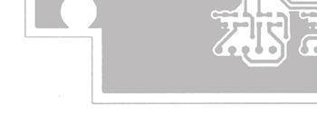
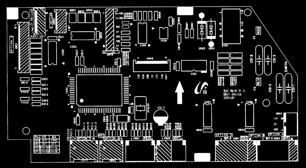
44 9-3 Outdoor Main PCB Inverter PCB Connector : SMW200-07(WHT) Display PCB Connector : SMW200-05(WHT) OLP/Cond. Temperature Sensor : SMAW250A-04(WHT) Outdoor/Discharge Temperature Sensor : SMAW250A-04(RED) EEV Connector : SMAW250A-06(WHT) DC5V Connector : SMW250-03(WHT) Communication 9-3
45 10. Operating Instructions 10-1 Name of Each Part Indoor Unit Air Inlet Temperature sensor Air filter (under the grille) Air flow blades (outlet) Operation indicator (GREEN) Timer indicator (GREEN) Turbo indicator (RED) On/Off button Air Inlet (Rear) Air Outlet Connection Valve (Inside) 10-1
46 10-2 Wireless Remote Control-Buttons and Display Transmission indicator Temperature and Timer setting Battery life indicator Operation modes indicator ( AUTO, COOL, DRY, FAN, HEAT) Airflow direction Fan speed & Silence indicator 1 Hour Timer indicator On Timer indicator Off Timer indicator Turbo function indicator Sleep mode indicator Energy saving indicator Turbo button Power(On/Off) button 1 Hour Timer button Mode selection button (AUTO, COOL, DRY, FAN, HEAT) Temperature adjustment button Fan speed adjustment button & Silence mode button Airflow control button Energy Saving button Good Sleep button Timer Set/Cancel button On Timer button Battery check button Off Timer button 10-2
47 10-3 Main Function Basic Function Mode Explanation Remark Auto Mode Press the button on the remote control until is displayed. Cool Mode Press the button on the remote control until is displayed. Press the displayed. button to select the fan speed until the required setting is Automatic (rotated : ) Silence mode Low Medium High Maximum Heat Mode Press the button on the remote control until is displayed. Press the displayed. button to select the fan speed until the required setting is Automatic (rotated : ) Silence mode Low Medium High Maximum 10-3
48 Operating Instructions Basic Function(cont.) Mode Explanation Remark Dry Mode Press the button on the remote control until is displayed. Fan Mode Press the button on the remote control until is displayed Applied Function Mode Explanation Remark Turbo Function Press the button. After 30 minutes, the air conditioner is reset automatically to the previous mode, temperature and fan settings. You can select the Turbo function in the Auto, Cool and Heat mode. If you select this function in the Dry or Fan mode, it will return to the Auto mode. good' sleep Mode Press the button until the indicator appears on the remote control. 10-4
49 11. Troubleshooting 11-1 Items to be checked first 1. The input voltage should be rating voltage ±10% range. The air conditioner may not operate properly if the voltage is out of this range. 2. Is the link cable linking the indoor unit and the outdoor unit linked properly? The indoor unit and the outdoor unit shall be linked by 5 cables. Check the terminals if the indoor unit and outdoor unit are properly linked by the same number of cables. Otherwise the air conditioner may not operate properly. 3. When a problem occurs due to the contents illustrated in the table below it is a symptom not related to the malfunction of the air conditioner. Operation of air conditioner Explanation 1 The OPERATION indication LED(BLUE) blinks when a power plug of the indoor unit is plugged in for the first time. It indicates power is on. The LED stops blinking if the operation ON/OFF button on the remote control unit is pushed. 2 In a COOL operation mode, the compressor does not operate at a room temperature higher than the setting temperature that the INDOOR FAN should operate. [In case of heat pump model] In a HEAT operation mode, the compressor does not operate at a room temperature lower than the setting temperature that indoor fan should operate. In happens after a delay of 3 minutes when the compressor is reoperated. The same phenomenon occurs when a power is on. As a phenomenon that the compressor is reoperated after a delay of 3 minutes, the indoor fan is adjusted automatically with reference to a temperature of the air blew. 3 Fan speed setting is not allowed in DRY( ) mode. The speed of the indoor fan is set to LL in DRY mode. Fan speed is selected automatically in AUTO mode. 4 Compressor stops operation intermittently in DRY( ) mode. 5 Timer LED(ORANGE) of the indoor unit lights up and the air conditioner does not operate. 6 The compressor stops intermittently in a COOL mode or DRY mode, and fan speed of the indoor unit decreases. 7 [In case of heat pump model] Compressor of the outdoor unit is operating although it is turned off in a HEAT mode. 8 [In case of heat pump model] The compressor and indoor fan stop intermittently in HEAT mode. 9 [In case of heat pump model] Indoor fan and outdoor fan stop operation intermittently in a HEAT mode. Compressor operation is controlled automatically in DRY mode depending on the room temperature and humidity. Timer is being activated and the unit is in ready mode. The unit operates normally if the timer operation is cancelled. The compressor stops intermittently or the fan speed of the indoor unit decreases to prevent inside/outside air frozen depending on the inside/outside air temperature. When the unit is turned off while de-ice is activated, the compressor continues operation for up to 9 minutes(maximum) until the deice is completed. The compressor and indoor fan stop intermittently if room temperature exceeds a setting temperature in order to protect the compressor from overheated air in a HEAT mode. The compressor operates in a reverse cycle to remove exterior ice in a HEAT mode, and indoor fan and outdoor fan do not operate intermittently for within 20% of the total heater operation 11-1
50 11-2 Fault Diagnosis by Symptom Power (completely dead)-initial diagnosis 1. Checklist : 1) Is input voltage normal? 2) Is AC power linked correctly? 3) Is input voltage of DC regulator IC KA7805 (IC02) normal? (11VDC-12.5VDC) 4) Is output voltage of DC regulator IC KA7805 (IC02) normal? (4.5VDC-5.5VDC) 2. Troubleshooting procedure Unplug the power cord and plug it after 30 seconds Press the Power Button on the remote control unit to operate the air conditioner operate Check the display board does not operate Check the indoor unit control board Check whether 2 wires of power cord are connected correctly to the terminal block and control board. Reconnect wires correctly Check whether the fuse on the control board is normal. FUSE(F701) : T3.15[A]/250[V] Replace fuse Check the output of SMPS on the control board. Input power: AC230±15%[V] IC02 Input: DC12[V] IC02 output: DC5[V] PCB should be replaced Check the setting temperature 11-2
51 Troubleshooting The Outdoor unit power supply error 1. Checklist : 1) Are the input power voltage and the power connection correct? 2) Is there no Fuse short in the indoor unit and outdoor unit? 3) Is the cable connected correctly between the indoor unit and outdoor unit in order. 4) Is the wire connected correctly to the terminal block of the indoor unit and outdoor unit? 2. Troubleshooting procedure Is the voltage of indoor unit terminal block 1 and 2 correct after power input? Is the R701 resistance of indoor PCB 200Ω? Exchange the PCB. Is the indoor unit fuse normal? Exchange the fuse. Pull out the power cord and execute the following step after 30 seconds. Is the outdoor unit normal? Exchange the fuse. Is the outdoor unit normal? Is the reactor connected correctly? Connect the reactor wire. Is the +, - of C102 short? Disassemble the PCB from the case. Is there no error at the insertion of PCB? Exchange the PCB. Exchange the PCB. Is the +,- of C102 short? Are the BLDC FAN Wire 1 and 3 short? Exchange the PCB. Exchange the BLDC FAN. rmal Operation Exit 11-3
52 Troubleshooting When the Up/Down Louver Motor Does t Operate. (Initial Diagnosis) 1. Checklist : 1) Is input voltage normal? 2) Is the Up/Down louver motor properly connected with the connector (CN61)? 2. Troubleshooting procedure Unplug the power cord and plug it after 30 seconds Is STD lamp blinking? Check as in the procedure Power. Does operation start when swing button of the remote control unit pushed? rmal Voltage at pin #30~#34 of micom (IC04) change?(squarewave) Micom (IC04) is faulty. Voltage at pin #2 ~ #5 of CN61(motor connector) change?(squarewave) Driver IC05/06 (ULN2003A) is faulty. Up/Down louver motor is faulty. 11-4
53 Troubleshooting The Outdoor unit Fan error 1. Checklist : 1) Are the input power voltage and the power connection correct? 2) Is the motor wire connected to the outdoor PCB correctly? 3) Is there no assembly error or none-assembly in the terminal of motor wire connector? 4) Is there no obstacle at the surrounding of motor and propeller? 2. Troubleshooting procedure Is the Pin voltage of CN01 #1, #3 over 250V? Follow the Check Procedure of outdoor unit power supply error check. Is the Pin voltage of CN01 #3, #5 within 1V~5V during the operation? Does the Pin voltage of IC01(MICOM).13 change?(square-wave) FAN DRIVE CIRCUIT (Q901,Q902 etc.) error Exchange the PCB. Exchange the PCB. MICOM Error Is the Pin voltage of CN01 #6 changed during the operation?(square-wave) Pull out the power cord and execute the following step after 30 seconds. Disassemble the BLDC FAN Wire. Is the short between the BLDC FAN Wires? Exchange the PCB. Exchange the BLDC FAN MOTOR. Exchange the PCB. 11-5
54 Troubleshooting Total current Trip error 1. Checklist : 1) Is the input power voltage proper? 2) Is the refrigerant charged properly? 3) Does the compressor rotate normally? (Reverse rotation, Locking etc.) 4) Dose the outdoor fan operate normally? (Fan propeller loss, Motor error etc.) 5) Is the installation condition of outdoor unit good? (Piping, Space etc.) 6) Is there no ventilation obstruction at the surrounding of outdoor? (Outdoor unit cover, Fan front obstruction etc.) 2. Troubleshooting procedure Is the installation of outdoor unit good? Reinstall and remove the obstruction. Dose the compressor rotate normally? Exchange the compressor. Is the assembly of R418, R413, IC41, C437 and the peripheral part good? Exchange the PCB. Pull out the power cord and exchange the PCB from the case after 30 seconds. Is the assembly of Micom and peripheral circuit part good? Exchange the PCB. Check again after assembly of PCB. 11-6
55 Troubleshooting In case of heating at the cooling mode or cooling at the heating mode 1. Troubleshooting procedure Is the Thermo off? Change the setting temperature of remote control. Is the unit in the defrosting operation? Operate it with a heating mode as soon as the defrosting is finished. Is the compressor in 3 minutes off? After 3 minutes, cooling and heating start automatically. Indoor operation SW is on. Turn the SW On. Is much frost in the heat exchanger? Is the outdoor air sensor and outdoor heat exchanger attached correctly? Attach the sensor correctly. Over shortage of the refrigerant Does the 4 way valve operate normally? Is the 4 way valve connector connected correctly? Connect the connecter correctly. Check the resistance value of 4 way valve coil. NG 4-WAY valve coil error OK Dose the voltage of AC 220V apply to the connector of 4 way valve coil during the operation? Exchange the outdoor PCB. Go to the next page 4 way valve main body error 11-7
56 Troubleshooting In case of heating at the cooling mode or cooling at the heating mode(cont.) From the previous page Does the EEV operate normally? Is much frost in the heat exchanger? Connect the connector. Check the resistance value of EEV coil. NG EEV coil error OK Is much frost in the heat exchanger? Exchange the out PCB. EEV main body error Does the outdoor fan operate at the operation of compressor? The over shortage of refrigerant, Insufficient Capacity, Load estimation error Is the outdoor fan connected correctly? Connect the connector. Check the resistance value of outdoor fan. NG Outdoor fan error OK Dose the voltage of DC300V apply to the connector of outdoor fan during the operation of outdoor unit? Check the motor wire. Outdoor PCB error 11-8
57 Troubleshooting Outdoor temperature sensor error 1. Checklist : 1) Is the sensor connector connected correctly? 2) Is the sensor placed correctly? 3) Does the both terminal of sensor satisfy the resistance value in accordance with temperature? 4) Is the resistance value of sensor connection pull_up correct? 2. Troubleshooting procedure Is the sensor connector connected correctly in accordance with a color? Reconnect the sensor connector. Is the temperature sensor connected correctly without separation? Change the position of sensor. Does the both terminal of sensor satisfy the resistance value in accordance with temperature? (Refer to the R/T TABLE) Exchange the sensor. Is the resistance value of sensor connection pull_up 18.2K? Exchange the PCB. Exchange the PCB. rmal operation Exit
58 Troubleshooting Discharge temperature sensor error 1. Checklist : 1) Is the sensor connector connected correctly? 2) Is the sensor placed correctly? 3) Does the both terminal of sensor satisfy the resistance value in accordance with temperature? 4) Is the resistance value of sensor connection pull_up correct? 2. Troubleshooting procedure Is the sensor connector connected correctly in accordance with a color? Reconnect the sensor connector. Is the temperature sensor connected correctly without separation? Change the position of sensor. Does the both terminal of sensor satisfy the resistance value in accordance with temperature? (Refer to the R/T TABLE) Exchange the sensor. Is the resistance value of sensor connection pull_up 24K? Exchange the PCB. Exchange the PCB. rmal operation Exit
59 Troubleshooting Coil temperature sensor error 1. Checklist : 1) Is the sensor connector connected correctly? 2) Is the sensor placed correctly? 3) Does the both terminal of sensor satisfy the resistance value in accordance with temperature? 4) Is the resistance value of sensor connection pull_up correct? 2. Troubleshooting procedure Is the sensor connector connected correctly in accordance with a color? Reconnect the sensor connector. Is the temperature sensor connected correctly without separation? Change the position of sensor. Does the both terminal of sensor satisfy the resistance value in accordance with temperature? (Refer to the R/T TABLE) Exchange the sensor. Is the resistance value of sensor connection pull_up 18.2K? Exchange the PCB. Exchange the PCB. rmal operation Exit
60 Operating Instructions and Installation Sensor R-T Table (Resistance-Temperature) 1. Discharge Temp. Sensor RESISTANCE : 200.0kΩ at 25 C (77 F) RESISTANCE TOLERANCE : ±5% TEMP.( C) TEMP.( F) MAX (kω) CENTER (kω) MIN (kω)
61 Operating Instructions and Installation Sensor R-T Table (Resistance-Temperature) 2. Outdoor Coil Temp. Sensor, Outdoor Air Temp. Sensor Indoor Coil Temp. Sensor, Indoor Air Temp. Sensor RESISTANCE : 10.0kΩ at 25 C (77 F) RESISTANCE TOLERANCE : ±1% TEMP.( C) TEMP.( F) MAX (kω) CENTER (kω) MIN (kω) TEMP. TOLERANCE. ( F)
62 Troubleshooting Fan error 1. Checklist : 1) Isn t the fan locked? 2) Is the sensor placed correctly? 3) Does the both terminal of sensor satisfy the resistance value in accordance with temperature? 4) Is the resistance value of sensor connection pull_up correct? 2. Troubleshooting procedure Isn't the Fan locked? Remove the Fan lock. Is the connector connected correctly? Connect the connector. Is the color of Fan wire matched correctly? Exchange the Fan. Exchange the PCB. rmal operation Exit 11-14
63 Troubleshooting DC-Link voltage sensor error 1. Checklist : 1) Is the voltage of indoor unit terminal block 1, 2 correct after power supply? 2) Is the capacitor(c101, C102, C103) for DC-Link assembled in accordance the specification? 3) Are R112, R113, R Kohm? 4) Is R Kohm? 2. Troubleshooting procedure Is the voltage of indoor unit terminal block 1, 2 correct after power supply? Apply the troubleshooting for outdoor unit power supply error. Is the capacitor(c101, C102, C103) for DC-Link assembled in accordance the specification? Connect the connector. Are R113, R114, R kohm? Exchange the PCB. Is R kohm? Exchange the Fan. Exchange the PCB. rmal operation Exit 11-15
64 Troubleshooting O.C.(Over Current) error 1. Checklist : 1) Is the Shunt resistance value correct? 2) Is the condition of surrounding temperature abnormal overload? 3) Is there any problem as like the temperature sensor separation or measurement value error? 4) Is the interphase resistance of compressor normal? 2. Troubleshooting procedure Restart after power off. Is the O.C.(Over Current) error occurred? Terminate the service. Is the Shunt resistance value normal? Exchange the PCB. Is the interphase resistance value of compressor (u v, v w, w u) normal? Exchange the Compressor. Is the compressor body and interphase resistance insulated? Exchange the Compressor. Is the condition of indoor/outdoor temperature normal load? Restart after returning to the normal load. Is the O.C. error occurred again? Terminate the service. Is the position of temperature sensor and the sensing value normal? Correct the sensor position or exchange the sensor. Is the connection cable for the compressor and power terminal normal? Correct the cable connection. Exchange the PCB
65 Troubleshooting Communication error 1. Checklist : 1) Is the communication cable between the indoor unit and outdoor unit connected correctly? 2) Isn t the power cable and communication cable error? 2. Troubleshooting procedure Restart after power off. Is the communication error occurred again? Terminate the service. Isn't the power cable and communication cable error? Correct the wrong wiring. Is the connection of communication cable normal? Correct the connection of communication cable. Is it the outdoor 2 Micom(Inverter + Main) model? Exchange the indoor/outdoor unit PCB. Exchange the outdoor unit PCB
66 Troubleshooting Compressor start error 1. Checklist : 1) Is the connection of cable for the compressor and power? 2) Is the interphase resistance of compressor normal? 2. Troubleshooting procedure Restart after power off. Is the restart error occurred again? Terminate the service. Is the interphase resistance value of compressor (u v, v w, w u) normal? Exchange the compressor. Is the compressor body and interphase resistance insulated? Exchange the compressor. Is the connection cable for the compressor and power terminal normal? Correct the cable connection. Exchange the PCB
67 Troubleshooting Compressor lock error 1. Checklist : 1) Is the connection of cable for the compressor and power? 2) Is the interphase resistance of compressor normal? 2. Troubleshooting procedure Restart after power off. Is the lock error occurred again? Terminate the service. Is the interphase resistance value of compressor (u v, v w, w u) normal? Exchange the compressor. Is the compressor body and interphase resistance insulated? Exchange the compressor. Is the connection cable for the compressor and power terminal normal? Correct the cable connection. Exchange the PCB
68 Troubleshooting DC Link Over voltage/ Low voltage error 1. Checklist : 1) Is the power voltage normal? 2) Is the voltage of front and back terminal of indoor(outdoor) power relay normal? 3) Is the resistance value for DC Link voltage detection NORMAL? 4) Is the resistance value of DC Link discharge normal? 5) Is the appearance of DC Link Capacitor normal? 2. Troubleshooting procedure Restart after power off. Is the DC Link voltage error occurred again? Terminate the service. Is the power voltage normal? Terminate the service. Is the front and back terminal voltage of indoor/outdoor power relay normal? Exchange the PCB. Reassembly the PCB. Is the appearance of DC Link Capacitor normal? Exchange the PCB. Is the resistance for the detection of DC Link voltage normal? Exchange the PCB. Is the resistance value of DC Link discharge normal? Exchange the PCB. Is the reactor insulation damaged? Exchange the PCB. Exchange the reactor
69 Troubleshooting When the remote control is not receiving 1. Check if the connector was normally assembled. 2. Put the set in operation and check the voltage of. 15(+) and. 16(-) of the main PCB CN91 while operating the remote control. When the voltage descends below 3V, the assembly module PCB is normal and the main PCB is poor. Then replace the main PCB. 3. Replace the assembly display PCB because the module PCB is poor if the voltage between. 15~16 of CN91 maintains 5V after the remote control starts operation The others 1. AC Line Zero Cross Signal OUT Check the assembly condition of peripheral part of IC21, ZD21, ZD20 and D200 on the PCB. 2. Capacity miss match Check again the indoor unit option code
70 11-3 PCB Inspection Method Pre-inspection tices 1. Check if you pulled out the AC power plug when you eliminate the PCB or front panel. 2. Don t hold the PCB side not impose excessive force on it to eliminate the PCB. 3. Don t pull the lead wire but hold the whole housing to connect or disconnect a connector to the PCB. 4. In case of outdoor PCB disassembly, check first the complete discharge of condenser (C103) after 30 seconds power off Inspection Procedure 1. Check connector connection and peeling of PCB or bronze coating pattern when you think the PCB is broken. 2. The PCB is composed of the 3 parts. 1. Indoor Main PCB Part : MICOM and surrounding circuit, relay, room fan motor driving circuit and control circuit, sensor driving circuit, power circuit of DC12V and DC5V, and buzzer driving circuit. 1. Display part : LED lamp, Switch, Remocon module 1. Outdoor Main PCB part : MICOM and surrounding circuit. IPM and PFC circuit and control circuit. 1. EMI PCB Part : Line filter and ise Capacitor, Varistor Indoor Detailed Inspection Procedure Procedure Inspection Method Cause 1 Plug out and pull the PCB out of the electronic box. Check the PCB fuse. 2 Supply power. If the operating lamp twinkles at this time, the above 1)~3) have no relation. 1) Is the fuse disconnected? Over current Indoor Fan Motor Short AC Part Pattern Short of the MAIN PCB Checking the power voltage. 1) Is the DB71 input voltage AC200V~AC240V? Power Cord is fault, Fuse open. Wrong Power Cable Wiring, AC Part is faulty. 2) Is the voltage between both terminals of the C104 on the 2 nd side of the transformer DC12V ±0.5V? Switching Trans or Power Circuit is faulty 3) Is the voltage between both terminals of OUT and GND of IC19(KA78L05) DC5V ±0.5V? Power Circuit is faulty, Load Short 3 Press the ON/OFF button. Checking the power voltage. 4 Press the ON/OFF button. 1. FAN Speed [High] 2. Continuous Operation 1) Is the voltage over AC180V being imposed on 1) terminal #3 and #5 of the fan motor connector(cn72)? 2) Check the voltage of both terminals of terminal block 1 and N(1) after 3 minute operation.: AC220V 1) Is the voltage over AC180V being imposed on 1) terminal #3 and #5 of the fan motor connector(cn72)? Relay(RY71) Coil Disconnection, IC05 is faulty Relay(RY71) Contact is faulty Fan Motor of the indoor is faulty 2) The fan motor of the indoor unit doesn t run. Fan Motor Connector(CN72) is faulty 3) The power voltage between terminal #3 and #5 of the connector(cn72) is 0V. ASS Y Main PCB is faulty Connection is faulty 11-22
71 Troubleshooting Outdoor Detailed Inspection Procedure Procedure Inspection Method Cause 1 Wait 30 seconds over after disconnecting the power cable Check the outdoor PCB. 1) Is C101 discharged? 2) Is the resistance of both terminals of C101 opened? 3) Is the fuse of EMI PCB normal? 4) Is the reactor wire connected? Over Current Inner short of PCB BLDC FAN Motor Error 2 Check the Outdoor unit PCB. 1) Is R ohm? 2) Does ry74 operate normally? (IC05 & 16:0V, 1:5V) 3) Is the fuse(f701) normal? 4) Is the Sub PCB assembled normally? Outdoor PCB Error SUB Relay(RY74) Error IC05 Error Indoor PCB Error 3 Check the LED lighting after power supply. 1) rmal: Red: Light On, Green: Flickering, Yellow: Light Off? 2) Is the voltage of C V over? 3) Is the input of IC19 8V, and the output 5V? 4) Recheck after disassembling BLDC FAN Wire. Inner short of outdoor PCB Wrong assembly of outdoor PCB BLDC FAN Error 4 Check the condition of indoor & outdoor connection cable. 1) Is the green LED light on once per second? 2) Is the indoor & outdoor connection able connected in order? 3) Is the grounding wire connected to the both of indoor & outdoor unit? 4) Is the voltage of terminal block N(1), 225V? Wrong connection of Indoor/Outdoor wiring Wrong assembly of outdoor communication circuit 5 Check the Comp Wire. 1) Is it connected red, blue, and yellow in order in counterclockwise. 2) Are the valve and its installation condition good? 3) Is the installation condition of outdoor unit? Wrong assembly Installation condition is bad. 6 Check the BLDC Fan. 1) Is CN01 1, 3 over 250V? 2) Is CN01 3, 5 within 1V~5V? 3) Is the voltage of CN01 6 changed? 4) Is the resistance of BLDC Motor 1, 3 opened after power off? Outdoor PCB Error BLDC Motor Error 11-23
72 11-4 Main Part Inspection Method Part Breakdown Inspection Method Room Temperature Sensor Measure resistance with a tester rmal At the normal temperature 37kΩ~ 8.3kΩ(-7 C~+30 C) *Refer to Table Abnormal, 0Ω... Open or Short Room Fan Motor Measure the resistance between terminals of the connector (CN72) with a tester. rmal At the normal temperature (10 C ~ 30 C) Compare terminal Resistance Remark Yellow, Blue 404.4Ω ± 10% Main Yellow, Red 340Ω ± 10% Sub Abnormal, 0Ω... Open or Short Stepping Motor Measure the resistance between the red wire and each terminal wire with a tester. rmal Abnormal About 300Ω at the normal temperature (20 C ~ 30 C), 0Ω... Open or Short 11-24
73 12. Block Diagram 12-1 Indoor Unit CONTROLLER * : OPTION IC-MCU HEAT EXCHANGER SENSOR BLADE CONTROL ROOM TEMPERATURE SENSOR INDOOR FAN MOTOR CONTROL INFRARED SIGNAL REMOTE CONTROL OSCILLATION CIRCUIT OUTDOOR COMMUNICATION POWER RELAY CONTROL TEMPERATURE CONTROL TIMER BUZZER MELODY CONTROL ANION CONTROL ZERO VOLTAGE DETECT DISPLAY PART TEMPERATURE OPERATION AUTO CLEAN TURBO ENERGY SAVING TIMER ANION FAN SPEED POWER ON/OFF MODE (AUTO, COOL, DRY, FAN, HEAT) COMPRESSOR CONTROL SIGNAL STEPPING MOTOR CONTROL SIGNAL TRIGGER SIGNAL SSR INDOOR FAN MOTOR TURBO OPERATION BUZZER MELODY CONTROL SIGNAL ANION CONTROL SIGNAL* COMMUNICATION SIGNAL OUTDOOR UNIT FAN SPEED SELECT (H/M/L/ AUTO) BLADE-H MOVING SELECT STEPPING MOTOR DRIVE BUZZER COMPRESSOR OUTDOOR FAN MOTOR 4-WAY VALVE ON, OFF TIMER SELECT/CANCEL BUZZER DRIVE ANION DRIVE* ANION TEMPERATURE SELECT(UP/DOWN) STEPPING MOTOR : BLADE CONTROL SLEEP OPERATION MELODY CONTROL PART DC5V ANION SELECT VOLTAGE REGULATOR AUTO CLEAN SELECT SPEAKER OPTION ENERGY SAVING SELECT DC12V SOUND ON/OFF SELECT SMPS POWER BLOCK DIGITAL ON/OFF DC5V DC12V AC INPUT AC230V DC25V 12-1

74 Block Diagram INDOOR FAN CONTROL BUZZER CONTROL SMPS 485 COMMUNICATION SUB-PCB 12-2
75 12-2 Outdoor Unit CONTROLLER MAIN-IC-MCU OUTDOOR TEMPERATURE SENSOR DISCHARGE TEMPERATURE SENSOR CONDENSOR TEMPERATURE SENSOR AC FAN CONTROL EEV CONTROL 4-WAY CONTROL LED CONTROL INDOOR COMMUNICATION OSCILLATION CIRCUIT OSCILLATION CIRCUIT INV-IC-MCU BLDC FAN CONTROL PFC CONTROL COMPRESSOR CONTROL (BLDC) LED CONTROL EEPROM R/W COMPRESSOR AC ZERO CROSSING SIGNAL COMPRESSOR ZERO CROSSING SIGNAL BLDC FAN PULSE SIGNAL IPM FAULT SIGNAL DC VOLTAGE AC CURRENT FAN BLDC FAN CONTROL SIGNAL PFC CONTROL SIGNAL COMPRESSOR CONTROL (6P,BLDC) LED CONTROL SIGNAL 4-WAY VALVE EEV AC FAN CONTROL SIGNAL EEV CONTROL SIGNAL 4-WAY CONTROL SIGNAL LED CONTROL SIGNAL INDOOR COMMUNICATION SIGNAL INDOOR UNIT SMPS AC INPUT PFC CIRCUIT 12-3


76 Inverter PCB OUTDOOR FAN POWER RELAY IGBT B/D DIODE DC_LINK CAP SMPS IPM Main PCB DISPLAY CONTROL INV PCB CONNECTOR INDOOR COMMUNICATION CIRCUIT THERMISTOR CONNECTOR EEV CONNECTOR 12-4
SERVICE Manual FREE JOINT MULTI AIR CONDITIONER
 FREE JOINT MULTI AIR CONDITIONER INDOOR UNIT MH020FPEA MH023FPEA MH026FPEA MH035FPEA MH052FPEA MH8VP2-09 MH9VP2-07 MH9VP2-2 MH026FKEA MH035FKEA MH052FDEA OUTDOOR UNIT MH8VP2X MH9VP2X MH052FXEA2 MH068FXEA4
SERVICE Manual SYSTEM AIR CONDITIONER INDOOR UNIT GH052EAM GH070EAM OUTDOOR UNIT UH052EAMT UH070EAMT. 1. Product Specifications
 SYSTEM AIR CONDITIONER INDOOR UNIT GH052EAM GH070EAM OUTDOOR UNIT UH052EAMT UH070EAMT SERVICE Manual SYSTEM AIR CONDITIONER CONTENTS 1. Product Specifications 2. Disassembly and Reassembly 3. Set Up the
SERVICE Manual CASSETTE TYPE AIR CONDITIONER INDOOR UNIT KH026EAM KH035EAM OUTDOOR UNIT UH026EAM UH035EAM. 1. Product Specifications
 CASSETTE TYPE AIR CONDITIONER INDOOR UNIT KH026EAM KH035EAM OUTDOOR UNIT UH026EAM UH035EAM SERVICE Manual AIR CONDITIONER CONTENTS 1. Product Specifications 2. Disassembly and Reassembly 3. Block Diagrams
USER S MANUAL AQV09J Series AQV12J Series AQV18J Series AQV24J Series
 USER S MANUAL AQV09J Series AQV12J Series AQV18J Series AQV24J Series FRANÇAIS ENGLISH ESPAÑOL Split-type Air Conditioner (Cooling and Heating) E S F DB98-27555A(1) Safety Precautions Register your product
AIR CONDITIONER. Model : 1. Precautions. 2. Product Specifications. 3. Disassembly and Reassembly. 4. Troubleshooting. 5.
 SYSTEM AIR CONDITIONER Model : INDOOR UNIT AC012MNADCH/AA AC018MNADCH/AA AC024MNADCH/AA AC030MNTDCH/AA AC036MNTDCH/AA OUTDOOR UNIT AC012KXADCH/AA AC018JXADCH/AA AC024JXADCH/AA AC030JXADCH/AA AC036JXADCH/AA
USER S MANUAL AQV09V A Series AQV12V A Series AQV18V A Series AQV24V A Series
 USER S MANUAL AQV09V A Series AQV12V A Series AQV18V A Series AQV24V A Series ENGLISH FRANÇAIS ESPAÑOL Split - type Air Conditioner (Cooling and Heating) E S F DB98-27559A(1) Contents PREPARATION Safety
4. Disassembly and Reassembly
 4. Disassembly and Reassembly Stop operation of the air conditioner and remove the power cord before repairing the unit. 4-1 Indoor Unit 4-1-1 MH FPEA /MH VP2-1 Front Panel 1) Stop the air conditioner
Model name: AJ009JNNDCH AJ012JNNDCH AJ018JNNDCH AJ007JNADCH AJ009JNADCH AJ012JNADCH
 Model name: AJ009JNNDCH AJ012JNNDCH AJ018JNNDCH AJ007JNADCH AJ009JNADCH AJ012JNADCH MULTI AIR CONDITIONER INDOOR UNIT AJ018JNADCH AJ024JNADCH AJ009JNLDCH AJ012JNLDCH AJ018JNLDCH OUTDOOR UNIT AJ020JCJ2CH
ROOM AIR CONDITIONER INDOOR UNIT OUTDOOR UNIT AQ09A5(6)MA UQ09A5(6)MA AQ12A5(6)MC UQ12A5(6)MC SERVICE
MA UQ09A5(6)MA AQ12A5(6)MC UQ12A5(6)MC SERVICE") ROOM AIR CONDITIONER INDOOR UNIT AQ09A5(6)MA AQ2A5(6)MC OUTDOOR UNIT UQ09A5(6)MA UQ2A5(6)MC SERVICE Manual AIR CONDITIONER CONTENTS. Installation 2. Disassembly and Reassembly. Troubleshooting 4. Exploded
ROOM AIR CONDITIONER INDOOR UNIT AQ09A5(6)MA AQ2A5(6)MC OUTDOOR UNIT UQ09A5(6)MA UQ2A5(6)MC SERVICE Manual AIR CONDITIONER CONTENTS. Installation 2. Disassembly and Reassembly. Troubleshooting 4. Exploded
AIR CONDITIONER 4 WAY CASSETTE SERIES. 1. Precautions. 2. Product Specifications. 3. Disassembly and Reassembly. 4. Troubleshooting. 5.
 SYSTEM AIR CONDITIONER 4 WAY CASSETTE SERIES Model : INDOOR UNIT AC018JN4DCH/AA AC024JN4DCH/AA AC030JN4DCH/AA AC036JN4DCH/AA AC042JN4DCH/AA AC048JN4DCH/AA OUTDOOR UNIT AC018JXADCH/AA AC024JXADCH/AA AC030JXADCH/AA
SYSTEM AIR CONDITIONER
 SYSTEM AIR CONDITIONER AHU SERIES Model : INDOOR UNIT AC018KNZDCH/AA AC024KNZDCH/AA AC030KNZDCH/AA AC036KNZDCH/AA AC042KNZDCH/AA AC048KNZDCH/AA AC054KNZDCH/AA OUTDOOR UNIT AC018JXADCH/AA AC024JXADCH/AA
SERVICE Manual AIR CONDITIONER AW0719 AW Precautions. 2. Product Specifications. 3. Operating Instructions and Installation
 ROOM AIR CONDITIONER AW079 AW089 SERVICE Manual AIR CONDITIONER CONTENTS. Precautions 2. Product Specifications 3. Operating Instructions and Installation 4. Disassembly and Reassembly 5. Troubleshooting
WALL MOUNTED type SPLIT TYPE ROOM AIR CONDITIONER CONTENTS. Models
 SPLIT TYPE ROOM AIR CONDITIONER WALL MOUNTED type Models Indoor unit ASY9USCCW ASY9USCCW ASY12USCCW Outdoor unit AOY9USCC AOY9UFCC AOY12USCC CONTENTS SPECIFICATIONS................................... 1
RC-54CA RO-50CA RC-54HA RO-50HA. SPLIT TYPE AIR CONDITIONER CASSETTE TYPE (50Hz) Indoor unit Outdoor unit
 Indoor unit Outdoor unit") SPLIT TYPE AIR CONDITIONER CASSETTE TYPE (50Hz) Indoor unit Outdoor unit RCW-54CB RO-50CA RC-54CA RO-50CA RC-54HA RO-50HA CONTENTS SPECIFICATIONS OUTLINE AND DIMENTIONS CIRCUIT DIAGRAM REFRIGERANT SYSTEM
SPLIT TYPE AIR CONDITIONER CASSETTE TYPE (50Hz) Indoor unit Outdoor unit RCW-54CB RO-50CA RC-54CA RO-50CA RC-54HA RO-50HA CONTENTS SPECIFICATIONS OUTLINE AND DIMENTIONS CIRCUIT DIAGRAM REFRIGERANT SYSTEM
INSTALLATION MANUAL. Split-type Air Conditioner (Cooling and Heating) Outdoor Unit UQB09JJWC UQB12JJWC. Indoor Unit AQB09JJWC AQB12JJWC
 Outdoor Unit UQB09JJWC UQB12JJWC. Indoor Unit AQB09JJWC AQB12JJWC") AQB09JJ6WC_IM_E_2585 2006.4.17 4:26 PM Page 17 INSTALLATION MANUAL Indoor Unit AQB09JJWC AQB12JJWC Outdoor Unit UQB09JJWC UQB12JJWC ENGLISH FRANÇAIS ESPAÑOL Split-type Air Conditioner (Cooling and Heating)
AQB09JJ6WC_IM_E_2585 2006.4.17 4:26 PM Page 17 INSTALLATION MANUAL Indoor Unit AQB09JJWC AQB12JJWC Outdoor Unit UQB09JJWC UQB12JJWC ENGLISH FRANÇAIS ESPAÑOL Split-type Air Conditioner (Cooling and Heating)
Part 3 Troubleshooting
 Part Troubleshooting What is in this part? This part contains the following chapters: Chapter See page Troubleshooting 2 Error Codes: Hydro-box 7 Error Codes: Outdoor Units Error Codes: System Malfunctions
Service Manual & Installation Manual
 GE Consumer & Industrial Appliances Service Manual & Installation Manual Split System Air Conditioner Model numbers: GE AIR F24 GE AIR F34 GE AIR F41 1 2 3 Introduction and Features Model Remarks GE AIR
DESIGN & TECHNICAL MANUAL
 AIR CONDITIONER Wall mounted type DESIGN & TECHNICAL MANUAL For Extra Cold Climate Area INDOOR ASU18RLF ASU24RLF OUTDOOR AOU18RLXFWH AOU24RLXFWH DR_AS014EF_04 2017.03.10 Notices: Product specifications
R410A. WALL MOUNTEDtype INVERTER SPLIT TYPE ROOM AIR CONDITIONER. Models Indoor unit Outdoor unit AOYG07LEC AOYG09LEC AOYG12LEC AOYG14LEC
 SERVICE INSTRUCTION SPLIT TYPE ROOM AIR CONDITIONER WALL MOUNTEDtype INVERTER Models Indoor unit Outdoor unit ASYG07LECA ASYG09LECA ASYG12LECA ASYG14LECA AOYG07LEC AOYG09LEC AOYG12LEC AOYG14LEC R410A CONTENTS
SPLIT TYPE ROOM AIR CONDITIONER CEILING TYPE (60Hz)
") SPLIT TYPE ROOM AIR CONDITIONER CEILING TYPE (60Hz) Indoor unit MS6YF Outdoor unit MR6YF CONTENTS SPECIFICATIONS... OUTLINE AND DIMENSIONS... REFRIGERANT SYSTEM DIAGRAM.... CIRCUIT DIAGRAM... INDOOR PCB
SPLIT TYPE ROOM AIR CONDITIONER CEILING TYPE (60Hz) Indoor unit MS6YF Outdoor unit MR6YF CONTENTS SPECIFICATIONS... OUTLINE AND DIMENSIONS... REFRIGERANT SYSTEM DIAGRAM.... CIRCUIT DIAGRAM... INDOOR PCB
OWNER S INSTRUCTIONS MANUAL DE INSTRUCCIONES MANUEL D UTILISATION ISTRUZIONI PER L USO MANUAL DE INSTRUÇÕES GEBRAUCHSANWEISUNG π Ã
 OWNER S INSTRUCTIONS MANUAL DE INSTRUCCIONES MANUEL D UTILISATION ISTRUZIONI PER L USO MANUAL DE INSTRUÇÕES GEBRAUCHSANWEISUNG π Ã Indoor unit SH09BPD SH12BPD Outdoor unit SH09BPDX SH12BPDX Split-type
AIR CONDITIONER OUTDOOR UNIT INDOOR UNIT. 1. Precautions
 MULTI AIR CONDITIONER INDOOR UNIT AJ009JNNDCH/AA AJ012JNNDCH/AA AJ018JNNDCH/AA AJ007JNADCH/AA AJ009JNADCH/AA AJ012JNADCH/AA AJ018JNADCH/AA AJ024JNADCH/AA AJ009JNLDCH/AA AJ012JNLDCH/AA AJ018JNLDCH/AA AJ009NBNDCH/AA
YC ON-OFF SERIES. Service Manual
 YC ON-OFF SERIES Service Manual CONTENTS 1. Precaution... 3 1.1 Safety Precaution... 3 1.2 Warning... 3 2. Model Lists... 6 3. Dimension... 7 3.1 Indoor Unit... 7 3.2 Outdoor Unit... 11 4. Refrigerant
INSTALLATION MANUAL. Split-type Air Conditioner (Cooling and Heating) Indoor Unit AQB18J6WC AQB24J2WC. Outdoor Unit UQB18J6WC UQB24J2WC
 Indoor Unit AQB18J6WC AQB24J2WC. Outdoor Unit UQB18J6WC UQB24J2WC") AQB8J6WC_IM_E_25864 2006.4.4 3:29 PM Page 7 INSTALLATION MANUAL Indoor Unit AQB8J6WC AQB24J2WC Outdoor Unit UQB8J6WC UQB24J2WC ENGLISH FRANÇAIS ESPAÑOL Split-type Air Conditioner (Cooling and Heating)
AQB8J6WC_IM_E_25864 2006.4.4 3:29 PM Page 7 INSTALLATION MANUAL Indoor Unit AQB8J6WC AQB24J2WC Outdoor Unit UQB8J6WC UQB24J2WC ENGLISH FRANÇAIS ESPAÑOL Split-type Air Conditioner (Cooling and Heating)
DC INVERTER MULTI-SYSTEM AIR CONDITIONER
 TECHNICAL & SERVICE MANUAL OUTDOOR UNIT : CU-3KE19NBU CU-4KE24NBU CU-4KE31NBU DC INVERTER MULTI-SYSTEM AIR CONDITIONER Capacity at 0V 19,100 BTU/h,200 BTU/h 30,600 BTU/h Outdoor Model No. CU-3KE19NBU CU-4KE24NBU
R410A. WALL MOUNTEDtype INVERTER SPLIT TYPE ROOM AIR CONDITIONER. Models Indoor unit Outdoor unit AO*G09LTCN AO*G12LTCN AO*G14LTCN
 SERVICE INSTRUCTION SPLIT TYPE ROOM AIR CONDITIONER WALL MOUNTEDtype INVERTER Models Indoor unit Outdoor unit AS*G09LTCB AS*GLTCB AS*G4LTCB AO*G09LTCN AO*GLTCN AO*G4LTCN R40A CONTENTS. DESCRIPTION OF EACH
SERVICE INSTRUCTION R410A. WALL MOUNTEDtype INVERTER SPLIT TYPE ROOM AIR CONDITIONER. Models Indoor unit Outdoor unit AOU9RLS2H AOU12RLS2H AOU15RLS2H
 SERVICE INSTRUCTION SPLIT TYPE ROOM AIR CONDITIONER WALL MOUNTEDtype INVERTER Models Indoor unit Outdoor unit ASU9RLS ASURLS ASU5RLS AOU9RLSH AOURLSH AOU5RLSH R40A CONTENTS. DESCRIPTION OF EACH CONTROL
CEILING type (60Hz) SPLIT TYPE ROOM AIR CONDITIONER CONTENTS. Models
 SPLIT TYPE ROOM AIR CONDITIONER CONTENTS. Models") SPLIT TYPE ROOM AIR CONDITIONER CEILING type (60Hz) Models Indoor unit ABU6RSLX Outdoor unit AOU6RLX CONTENTS SPECIFICATIONS....................... OUTLINE AND DIMENSIONS............. REFRIGERANT SYSTEM
SPLIT TYPE ROOM AIR CONDITIONER CEILING type (60Hz) Models Indoor unit ABU6RSLX Outdoor unit AOU6RLX CONTENTS SPECIFICATIONS....................... OUTLINE AND DIMENSIONS............. REFRIGERANT SYSTEM
SPLIT TYPE ROOM AIR CONDITIONER. WALL MOUNTEDtype INVERTER. Models Indoor unit Outdoor unit AOU 9RLFW1 AOU12RLFW1 ASU 9RLF1 ASU12RLF1 R410A
 SERVICE INSTRUCTION SPLIT TYPE ROOM AIR CONDITIONER WALL MOUNTEDtype INVERTER Models Indoor unit Outdoor unit ASU 9RLF ASURLF AOU 9RLFW AOURLFW R40A CONTENTS. DESCRIPTION OF EACH CONTROL OPERATION. COOLING
Room Air Conditioner Service and Parts Manual
 Cool Dry Temp Mode Room Air Conditioner Service and Parts Manual F Fan Speed hr Timer 0n 0ff Money Saver Fan Only Auto Swing Power CP06 CP08 93011401_01 CONTENTS 1. PREFACE 1.1 SAFETY PRECAUTIONS...2 1.2
CASSETTE type INVERTER MULTI AIR CONDITIONER. Models AUY12LBAB AUY14LBAB AOY18LMAK2
 INVERTER MULTI AIR CONDITIONER CASSETTE type Models Indoor unit AUY12LBAB AUY14LBAB Outdoor unit AOY18LMAK2 CONTENTS SPECIFICATIONS..................... 1 OUTLINE AND DIMENSIONS........... 2 REFRIGERANT
SERVICE MANUAL MUZ-D30NA / - MUZ-D36NA / - MUY-D30NA / - MUY-D36NA / - OUTDOOR UNIT. No. OBH502. Models HFC. Revision E: REVISED EDITION-E R410A
 Revision E: Capacity corrections have been corrected [7-1. 2), 3)]. OBH502 REVISED EDITION-D is void. OUTDOOR UNIT SERVICE MANUAL HFC utilized R410A. OBH502 REVISED EDITION-E Models MUZ-D30NA / - 1 / -
DESIGN & TECHNICAL MANUAL
 AIR CONDITIONER Wall Mounted type DESIGN & TECHNICAL MANUAL INDOOR AS A09LEC AS A12LEC OUTDOOR AO R09LECN AO R12LECN 1.INDOOR UNIT : AS A09LEC AS A12LEC DTR_AS047E_01 2010.10.05 1. INDOOR UNIT CONTENTS
FLOOR CONSOLE / UNDER CEILING DUAL type (60Hz)
") SPLIT TYPE ROOM AIR CONDITIONER FLOOR CONSOLE / UNDER CEILING DUAL type (60Hz) Models Indoor unit MSYF Outdoor unit MRUYF CONTENTS SPECIFICATIONS... OUTLINE AND DIMENSIONS... REFRIGERANT SYSTEM DIAGRAM...
SPLIT TYPE ROOM AIR CONDITIONER FLOOR CONSOLE / UNDER CEILING DUAL type (60Hz) Models Indoor unit MSYF Outdoor unit MRUYF CONTENTS SPECIFICATIONS... OUTLINE AND DIMENSIONS... REFRIGERANT SYSTEM DIAGRAM...
SERVICE MANUAL MUZ-D30NA MUZ-D30NA- U1 MUZ-D36NA MUZ-D36NA- U1 MUY-D30NA MUY-D36NA OUTDOOR UNIT. No. OBH502. Wireless type Models HFC R410A
 OUTDOOR UNIT SERVICE MANUAL HFC utilized R410A. OBH502 Wireless type Models MUZ-D30NA MUZ-D30NA- U1 MUZ-D36NA MUZ-D36NA- U1 MUY-D30NA MUY-D36NA Indoor unit service manual MSZ-D NA Series (OBH501) MSY-D
TROUBLESHOOTING TROUBLESHOOTING. Indoor unit EEPROM parameter error. Indoor / outdoor units communication error. Zero-crossing signal detection error
 www.olmo-comfort.com TROUBLESHOOTING When below list for identification of error code occurs, please turn off air conditioner and disconnect power, and then contact the qualified professionals for service.
FLOOR CONSOLE / UNDER CEILING DUAL type
 SPLIT TYPE ROOM AIR CONDITIONER FLOOR CONSOLE / UNDER CEILING DUAL type Models Indoor unit ABU8RULX ABURULX Outdoor unit AOU8RLX AOURLX CONTENTS SPECIFICATIONS... OUTLINE AND DIMENSIONS... REFRIGERANT
Room Air Conditioner CP06 & CP08. Chill 115 Volts. Service & Parts Manual THE EXPERTS IN ROOM AIR CONDITIONING _02
 Room Air Conditioner Service & Parts Manual 2014-2015 CP06 & CP08 Chill 115 Volts THE EXPERTS IN ROOM AIR CONDITIONING 93011401_02 CONTENTS 1. PREFACE 1.1 SAFETY PRECAUTIONS...2 1.2 INSULATION RESISTANCE
SERVICE MANUAL ROOM AIR CONDITIONER TAN/TAG-A28FWIS TAN/TAG-A32FWIS CONTENTS
 SERVICE MANUAL ROOM AIR CONDITIONER TAN/TAG-A28FWIS TAN/TAG-A32FWIS CONTENTS SPECIFICATION... 1 FUNCTIONS... 5 SERVICE FUNCTION EXPLANATION... 7 OPERATION DETAILS... 8 TROUBLESHOOTING GUIDE... 13 PERFORMANCE
SERVICE Manual CEILING TYPE AIR CONDITIONER INDOOR UNIT FH052EZA FH070EZA OUTDOOR UNIT FH052EZX FH070EZX. 1. Product Specifications
 CEILING TYPE AIR CONDITIONER INDOOR UNIT FH052EZA FH070EZA OUTDOOR UNIT FH052EZX FH070EZX SERVICE Manual AIR CONDITIONER CONTENTS 1. Product Specifications 2. Trouble Shooting 3. Block Diagrams 4. Disassembly
ASU18RLF ASU24RLF AOU18RLXFW1 AOU24RLXFW1 SPLIT TYPE ROOM AIR CONDITIONER WALL MOUNTED TYPE CONTENTS
 SPLIT TYPE ROOM AIR CONDITIONER WALL MOUNTED TYPE Indoor unit ASU8RLF ASURLF Outdoor unit AOU8RLXFW AOURLXFW CONTENTS SPECIFICATIONS.................... DIMENSIONS........................ REFRIGERANT SYSTEM
ASU18RLF ASU24RLF AOU18RLXFWH AOU24RLXFWH CONTENTS WALL MOUNTED TYPE ROOM AIR CONDITIONER FOR EXTRA LOW TEMP. DISTRICT
 WALL MOUNTED TYPE ROOM AIR CONDITIONER FOR EXTRA LOW TEMP. DISTRICT Indoor unit ASU8RLF ASURLF Outdoor unit AOU8RLXFWH AOURLXFWH CONTENTS SPECIFICATIONS.................... DIMENSIONS........................
SERVICE MANUAL. No. OBH747 REVISED EDITION-A. Models HFC
 Revision A: MUZ-HM09/12NA- U8, MUZ-HM09/12NA2- U8, MUZ-HM15/18NA- U1, MUZ-HM15/18NA2- U1 and MUZ-HM24NA2- U1 have been added. Please void OBH747. OUTDOOR INDOOR UNIT UNIT SERVICE MANUAL HFC utilized R410A.
SERVICE INSTRUCTION R410A. WALL MOUNTEDtype SPLIT TYPE ROOM AIR CONDITIONER INVERTER. Models Indoor unit Outdoor unit AO* R09LECN AO* R12LECN
 SERVICE INSTRUCTION SPLIT TYPE ROOM AIR CONDITIONER WALL MOUNTEDtype INVERTER Models Indoor unit Outdoor unit AS* A09LEC AS* A12LEC AO* R09LECN AO* R12LECN R410A CONTENTS 1. DESCRIPTION OF EACH CONTROL
Fast Track Troubleshooting
 Fast Track Troubleshooting Models Covered: RF266AD**/XAA French Door Refrigeration IMPORTANT SAFETY NOTICE For Technicians Only This service data sheet is intended for use by persons having electrical,
SERVICE INSTRUCTION R410A. WALL MOUNTEDtype INVERTER SPLIT TYPE ROOM AIR CONDITIONER. Models Indoor unit Outdoor unit AO*G24LFL AO*G24LFCC AO*G30LFT
 SERVICE INSTRUCTION SPLIT TYPE ROOM AIR CONDITIONER WALL MOUNTEDtype INVERTER Models Indoor unit Outdoor unit AS*G4LFCA AS*G4LFCC AS*G0LFCA AO*G4LFL AO*G4LFCC AO*G0LFT R40A CONTENTS. DESCRIPTION OF EACH
SPLIT TYPE ROOM AIR CONDITIONER FLOOR CONSOLE / UNDER CEILING DUAL TYPE
 SPLIT TYPE ROOM AIR CONDITIONER FLOOR CONSOLE / UNDER CEILING DUAL TYPE Indoor unit ABYF8LAT ABYF8LAT ABYF8LAT ABYF8LAT ABYF8LBT ABYF8LBT ABYFLAT ABYFLAT ABYFLAT ABYFLAT ABYFLBT ABYFLBT Outdoor unit AOYA8LACL
SERVICE MANUAL OUTDOOR UNIT MUZ-FH06NAH MUZ-FH09NAH MUZ-FH06NA MUZ-FH09NA MUZ-FH09NA - 1 MUZ-FH09NAH - 1 MUZ-FH12NA MUZ-FH12NAH
 Revision D: Capacity corrections have been corrected [7-1. 2), 3)]. OBH684 REVISED EDITION-C is void. OUTDOOR UNIT SERVICE MANUAL HFC utilized R410A. OBH684 REVISED EDITION-D Models MUZ-FH06NA MUZ-FH09NA
DC INVERTER SPLIT SYSTEM AIR CONDITIONER
 AIR CONDITIONER TECHNICAL & SERVICE MANUAL KS1872 + C1872 + CL1872 KS2472 + C2472 + CL2472 FILE NO. Destination: North America DC INVERTER SPLIT SYSTEM AIR CONDITIONER Indoor Model No. KS1872 KS2472 Product
TECHNICAL & SERVICE MANUAL. Ceiling Concealed
 STAND BY DEFROST CHECK CLOCK ON OFF NOT AVAILABLE FILTER CHECK MODE TEST RUN FUNCTION SPLIT-TYPE, HEAT PUMP AIR CONDITIONERS TECHNICAL & SERVICE MANUAL Series SEZ Ceiling Concealed R40A.OC0 REVISED EDITION-A
Display Cases Deli Cases Service Manual
 Turbo Air Speed up the Pace of Innovation CAUTION! PLEASE KEEP POWER SWITCH ON BEFORE OPERATING THIS EQUIPMENT Display Cases Deli Cases Service Manual Please read this manual completely before attempting
SERVICE MANUAL MUY-GL24NA - U1. No. OBH733. Models HFC. Revision B: REVISED EDITION-B R410A
 Revision B: MUZ-GL09NA- U8 and MUZ-GL09NAH- U8 have been added. Please void OBH733 REVISED EDITION-A. OUTDOOR INDOOR UNIT UNIT SERVICE MANUAL HFC utilized R410A. OBH733 REVISED EDITION-B Models MUZ-GL09NA
SERVICE MANUAL 42QHF009DS* 42QHF012DS* 42QHF018DS* 42QHF022DS* 38QUS009DS* 38QUS012DS* 38QUS018DS* 38QUS022DS* Indoor unit.
 SERVICE MANUAL Indoor unit Outdoor unit 42QHF009DS* 42QHF012DS* 42QHF018DS* 42QHF022DS* 38QUS009DS* 38QUS012DS* 38QUS018DS* 38QUS022DS* INDEX PART1 GENERAL INFORMATION PART2 ELECTRICAL DIAGRAM PART3 TROUBLE
EVAPORATIVE AIR COOLER SERVICE MANUAL
 EVAPORATIVE AIR COOLER SERVICE MANUAL CAUTION: Before servicing the unit, read the Safety Precautions in this manual. Only for authorized service. MODEL NO.: CL30XC & CHL30XC (INDOOR USE ONLY) CONTENT
DESIGN & TECHNICAL MANUAL
 AIR CONDITIONER Wall mounted type DESIGN & TECHNICAL MANUAL INDOOR ASYG07LMCE ASYG09LMCE ASYG12LMCE ASYG14LMCE OUTDOOR AOYG07LMCE AOYG09LMCE AOYG12LMCE AOYG14LMCE DR_AS037EF_01 2016.12.05 Notices: Product
CASSETTE type INVERTER MULTI AIR CONDITIONER
 INVERTER MULTI AIR CONDITIONER CASSETTE type Models Indoor unit AUY12LBAB AUY14LBAB Outdoor unit AOY18LMAK2 CONTENTS SPECIFICATIONS..................... 1 OUTLINE AND DIMENSIONS........... 2 REFRIGERANT
TECHNICAL & SERVICE MANUAL WINDOW TYPE AIR CONDITIONER SA 183A FILE NO. SA 183A REFERENCE NO. SM Destination Australia SA-183A
 TECHNICAL & SERVICE MANUAL SA 183A FILE NO. WINDOW TYPE AIR CONDITIONER Model No. Product Code No. SA-183A 1 851 006 96 Destination Australia SA 183A REFERENCE NO. SM700514 IMPORTANT! Please Read Before
AIR CONDITIONER OUTDOOR UNIT AM036NXMDCR AM048NXMDCR AM053NXMDCR AM060NXMDCR. Product Specifications. Disassembly and Reassembly
 SYSTM AIR CONDITIONR OUTDOOR UNIT AM036NXMDCR AM048NXMDCR AM053NXMDCR AM060NXMDCR AIR CONDITIONR CONTNTS Product Specifications Disassembly and Reassembly Refrigerant pipe installation Troubleshooting
DESIGN & TECHNICAL MANUAL
 AIR CONDITIONER Wall mounted type DESIGN & TECHNICAL MANUAL INDOOR ASYG18KLCA ASYG24KLCA OUTDOOR AOYG18KLTA AOYG24KLTA DR_AS069EF_01 2018.03.16 Notices: Product specifications and design are subject to
AR09HSSDBWKNEU AR09HSSDBWKXEU AR12HSSDBWKNEU AR12HSSDBWKXEU AR12HSSDRWKNER AR12HSSDRWKXER
 AR09HSSDBWKNEU AR09HSSDBWKXEU AR2HSSDBWKNEU AR2HSSDBWKXEU AR2HSSDRWKNER AR2HSSDRWKXER AR09HSSDBWKNEU AR2HSSDBWKNEU AR2HSSDRWKNER AR09HSSDBWKXEU AR2HSSDBWKXEU AR2HSSDRWKXER Contents. Precautions - - Installing
CASSETTE type SPLIT TYPE AIR CONDITIONER. (60Hz) AUU18RCLX AUU24RCLX AUU36RCLX AUU42RCLX AOU18RLX AOU24RLX AOU36RLX AOU42RLX CONTENTS.
 AUU18RCLX AUU24RCLX AUU36RCLX AUU42RCLX AOU18RLX AOU24RLX AOU36RLX AOU42RLX CONTENTS.") SPLIT TYPE AIR CONDITIONER CASSETTE type (60Hz) Models Indoor unit AUU8RCLX AUURCLX AUU6RCLX AUURCLX Outdoor unit AOU8RLX AOURLX AOU6RLX AOURLX CONTENTS SPECIFICATIONS... DIMENSIONS... REFRIGERANT SYSTEM
SPLIT TYPE AIR CONDITIONER CASSETTE type (60Hz) Models Indoor unit AUU8RCLX AUURCLX AUU6RCLX AUURCLX Outdoor unit AOU8RLX AOURLX AOU6RLX AOURLX CONTENTS SPECIFICATIONS... DIMENSIONS... REFRIGERANT SYSTEM
TABLE OF CONTENTS REFRIGERATOR-FREEZER. Model No. NR-BN34FX1 Model No. NR-BN34FW1
 Order Number GORR1405001CE REFRIGERATOR-FREEZER Model No. NR-BN34FX1 Model No. NR-BN34FW1 Product-Color X:Stainless W:White Destination E(Europe Continental) B(U.K.) TABLE OF CONTENTS PAGE 1 Safety Precautions-----------------------------------------------
WALL MOUNTED type SPLIT TYPE ROOM AIR CONDITIONER. Models CONTENTS
 SPLIT TYPE ROOM AIR CONDITIONER WALL MOUNTED type Models Indoor unit ASY9USCCW ASY9USCCW ASY12USCCW Outdoor unit AOY9USCC AOY9UFCC AOY12USCC CONTENTS SPECIFICATIONS.................. 1 OUTLINE AND DIMENSIONS.........
TECHNICAL DATA & SERVICE MANUAL MTF94C5TAA
 TECHNICAL DATA & SERVICE MANUAL MTF94C5TAA 0.8180.472.0 07/2005 Page 1. SPECIFICATIONS 3 1-1 Unit Specifications 3 1-2 Major Component Specifications 4 2. DIMENSIONAL DATA 6 2-1 Unit Dimensions 6 3. ELECTRICAL
WALL MOUNTED type SPLIT TYPE ROOM AIR CONDITIONER CONTENTS. Models
 SPLIT TYPE ROOM AIR CONDITIONER WALL MOUNTED type Models Indoor unit ASY9USCCW ASY9USCCW ASY12USCCW Outdoor unit AOY9USCC AOY9UFCC AOY12USCC CONTENTS SPECIFICATIONS.................. 1 OUTLINE AND DIMENSIONS.........
Ductless Split Air Conditioner
 Ductless Split Air Conditioner Service Manual Indoor HSU09VHG(DB)-W HSUVHG(DB)-W HSU8VHH(DB)-W HSUVHG(DB)-W Outdoor HSU09VHG(DB)-G HSUVHG(DB)-G HSU8VHH(DB)-G HSUVHG(DB)-G Design may vary by model number.
DUCT type. Большая библиотека технической документации каталоги, инструкции, сервисные мануалы, схемы.
 SPLIT TYPE AIR CONDITIONER (50Hz) DUCT type Models Indoor unit Outdoor unit RD-25CA RD-25HA RD-30CA RD-30HA RO-25CA RO-25HA RO-30CA RO-30HA C O N T E N T S SPECIFICATIONS.............................................
OWNER S MANUAL. R 410A Ductless Split System Air Conditioner and Heat Pump
 R 410A Ductless Split System Air Conditioner and Heat Pump Models DLC4(A/H) Outdoor Unit, DLF4(A/H) Indoor Unit Sizes 9K, 12K, 18K, 24K, 30K and 36K Please read the operating instructions and safety precautions
TECHNICAL DATA & SERVICE MANUAL SPLIT SYSTEM AIR CONDITIONER INDOOR UNIT: ASR609CL ASR612CL ASR609CL ASR612CL
 TECHNICAL DATA & SERVICE MANUAL INDOOR UNIT: ASR609CL ASR612CL SPLIT SYSTEM AIR CONDITIONER Model No. Product Code No. ASR609CL 387006970 ASR612CL 387006971 0.8180.250.0 05/2002 IMPORTANT! Please read
SERVICE MANUAL OUTDOOR UNIT. No. OBH530. Models MU-GE50VB- E1 MUH-GE50VB- E1 HFC SPLIT-TYPE AIR CONDITIONERS R410A
 SPLIT-TYPE AIR CONDITIONERS OUTDOOR UNIT SERVICE MANUAL HFC utilized R410A. OBH530 Models MU-GE50VB- E1 - E1 Indoor unit service manual MS/MSH-GE VB Series (OBH529) CONTENTS 1. TECHNICAL CHANGES 2 2. PART
Fast Track Troubleshooting
 Fast Track Troubleshooting Publication # tsrs265td Revision Date 03/30/2011 Models Covered: RS265TDBP/XAA RS265TDPN/XAA RS265TDRS/XAA RS265TDWP/XAA IMPORTANT SAFETY NOTICE For Technicians Only This service
TECHNICAL & SERVICE MANUAL WINDOW TYPE AIR CONDITIONER SA 123A FILE NO. SA 123A REFERENCE NO. SM700513
 TECHNICAL & SERVICE MANUAL SA 123A FILE NO. WINDOW TYPE AIR CONDITIONER Model No. Product Code No. Destination SA-123A 1 851 006 95 Australia SA 123A REFERENCE NO. SM700513 IMPORTANT! Please Read Before
DuctlessAire ES Series. Service Manual 2016 ABSSA-B4-1601
 DuctlessAire ES Series Service Manual 2016 ABSSA-B4-1601 CONTENTS 1. Precaution... 1 1.1 Safety Precaution... 1 1.2 Warning... 1 2. Model list... 4 3. Dimension... 5 3.1 Indoor Unit... 5 3.2 Outdoor Unit...
KSIA SERIES SPLIT TYPE ROOM AIR CONDITIONER. For Split Wall Mounted Series R410a Inverter Model Type For F
 KSIA SERIES ro le oo SPLIT TYPE ROOM AIR CONDITIONER For Split Wall Mounted Series R410a Inverter Model Type For F KSIA009-H216-I / KSIA009-H216-O KSIA012-H216-I / KSIA012-H216-O KSIA018-H216-I / KSIA018-H216-O
SERVICE MANUAL K LIGHT COMMERCIAL
 SERVICE MANUAL 36 48 60K LIGHT COMMERCIAL Cassette indoor unit Under-ceiling indoor unit Ducted indoor unit 42QTD036DS* 42QTD048DS* 42QTD060DS* 42QZL036DS* 42QZL048DS* 42QZL060DS* 42QSM036DS* 42QSM048DS*
SERVICE Manual AIR CONDITIONER INDOOR UNIT SH09AWH SH09ZWH AQ09WHWE KFR-25G/SWA SH12AWH SH12ZWH AQ12WHWE KFR-35G/SWA
 ROOM AIR CONDITIONER INDOOR UNIT SH09AWH SH09ZWH AQ09WHWE KFR5G/SWA SHAWH SHZWH AQWHWE KFR5G/SWA OUTDOOR UNIT SH09AWHX SH09ZWHX UQ09WHWE KFR5W/SWA SHAWHX SHZWHX UQWHWE KFR5W/SWA SERVICE Manual AIR CONDITIONER
Split-type Room Air Conditioner (Cool) Aire acondicionado doméstico sistema Split (Refrigeración) Climatiseur de type Séparé (Refroidissement)
 Aire acondicionado doméstico sistema Split (Refrigeración) Climatiseur de type Séparé (Refroidissement)") OWNER S INSTRUCTIONS MANUAL DE INSTRUCCIONES MANUEL D UTILISATION Indoor unit AS24A5(6)RCD AST24A5(6)RB(E)D SC24AC5(6) SC24TA5(6)(8)D AS18A9(0)RB(C)(D)(E)D SC18ZA9(0)D SC18AC9(0) AS12AA(B)MB(E) SC12ZAA(B)
OWNER S INSTRUCTIONS MANUAL DE INSTRUCCIONES MANUEL D UTILISATION Indoor unit AS24A5(6)RCD AST24A5(6)RB(E)D SC24AC5(6) SC24TA5(6)(8)D AS18A9(0)RB(C)(D)(E)D SC18ZA9(0)D SC18AC9(0) AS12AA(B)MB(E) SC12ZAA(B)
SERVICE MANUAL MUZ-FE09NA MUZ-FE09NAH MUZ-FE12NA MUZ-FE12NA1 MUZ-FE12NAH MUZ-FE18NA OUTDOOR UNIT. No. OBH543 REVISED EDITION-F.
 Revision F: The descriptions of the expansion valve coil have been corrected. (10-4.) Some descriptions have been modified. Please void OBH543 REVISED EDITION-E. OUTDOOR UNIT SERVICE MANUAL HFC utilized
Fast Track Troubleshooting
 Fast Track Troubleshooting Models Covered: RS267TDBP/XAA RS267TDPN/XAA RS267TDRS/XAA RS267TDWP/XAA Publication # tsrs267td Revision Date 03/30/2011 IMPORTANT SAFETY NOTICE For Technicians Only This service
OWNER S INSTRUCTIONS MANUAL DE INSTRUCCIONES MANUEL D UTILISATION ISTRUZIONI PER L USO MANUAL DE INSTRUÇÕES GEBRAUCHSANWEISUNG
 OWNER S INSTRUCTIONS MANUAL DE INSTRUCCIONES MANUEL D UTILISATION ISTRUZIONI PER L USO MANUAL DE INSTRUÇÕES GEBRAUCHSANWEISUNG π Ã àçëíêìäñàü èéãúáéçäíöãü MH026FPEA MH035FPEA MH052FPEA ENGLISH ESPAÑOL
DESIGN & TECHNICAL MANUAL
 AIR CONDITIONER Wall mounted type DESIGN & TECHNICAL MANUAL INDOOR ASYG07KGTA ASYG09KGTA ASYG12KGTA ASYG14KGTA OUTDOOR AOYG07KGCA AOYG09KGCA AOYG12KGCA AOYG14KGCA DR_AS049EF_02 2017.10.11 Notices: Product
Room Air Conditioner CONTENTS CS-E9BKP CU-E9BKP5 CS-E12BKP CU-E12BKP5. Order No: MAC C2
 Order No: MAC008C Room Air Conditioner CS-E9BKP CU-E9BKP5 CS-EBKP CU-EBKP5 CONTENTS Page Page Features Functions Product Specifications 6 Dimensions 0 5 Refrigeration Cycle Diagram 6 Block Diagram 7 Wiring
Installation Instructions
 40MAQ High Wall Ductless Split System Sizes 09 to 36 Installation Instructions NOTE: Read the entire instruction manual before starting the installation TABLE OF CONTENTS PAGE SAFETY CONSIDERATIONS 2 PARTS
WINDOW TYPE ROOM AIR CONDITIONER OPERATION AND INSTALLATION MANUAL
 MODEL RA-0LDF RA-3LDF WINDOW TYPE ROOM AIR CONDITIONER OPERATION AND INSTALLATION MANUAL AIR DEFLECTORS VERTICAL DEFLECTORS Vertical de ectors at both sides of outlets can be set to either auto-swing or
Technical manual NIBE AG-AA10 Single split air to air heat pump
 Technical manual NIBE AG-AA10 Single split air to air heat pump TABLE OF CONTENTS 1 SCOPE... 4 2 DIMENSIONAL DATA AND EXTERIOR APPEARANCE... 5 3 TECHNICAL SPECIFICATIONS... 7 4 REFRIGERANT CIRCUIT... 10
SERVICE MANUAL MUZ-DM25VA - E1, ER1, ET1 MUZ-DM35VA - E1, ER1, ET1 OUTDOOR UNIT. No. OBH751. Models HFC R410A
 OUTDOOR UNIT SERVICE MANUAL HFC utilized R410A. Models MUZ-DM25VA - E1, ER1, ET1 MUZ-DM35VA - E1, ER1, ET1 Indoor unit service manual MSZ-DM VA Series (OBH750) CONTENTS 1. TECHNICAL CHANGES 2 2. PART NAMES
Service Manual. Room Air Conditioner Split Wall-Mounted Type. Applies to: HSG-09HRN1 HSG-12HRN1 HSG-18HRN1 HSG-24HRN1
 Service Manual Room Air Conditioner Split Wall-Mounted Type Applies to: HSG-09CRN1 HSG-12CRN1 HSG-18CRN1 HSG-24CRN1 HSG-09HRN1 HSG-12HRN1 HSG-18HRN1 HSG-24HRN1 NOTE: Please read this first before servicing
Fast Track Troubleshooting
 Models Covered: RF266AA**/XAA RF266AB**/XAA RF266**/XAA French Door Refrigeration NOTICE: RF266AA & AB** 01/09 Parts Change: Refer to bulletin. All Water Tank Parts Forced Mode: Press the Pwr Freeze Fridge
SERVICE MANUAL MSZ-GL06NA - U1 MSZ-GL09NA - U1 MSZ-GL12NA - U1 MSZ-GL15NA - U1 MSZ-GL18NA - U1 MSZ-GL24NA - U1
 Revision B: 3. SPECIFICATION has been corrected. Please void OBH732 REVISED EDITION-A. INDOOR UNIT SERVICE MANUAL. OBH732 REVISED EDITION-B Models MSZ-GL06NA - U1 MSZ-GL09NA - U1 MSZ-GL12NA - U1 MSZ-GL15NA
TECHNICAL DATA & SERVICE MANUAL SPLIT SYSTEM AIR CONDITIONER INDOOR UNIT: CAF94R5 CAF124R5 CAF94R
 TECHNICAL DATA & SERVICE MANUAL INDOOR UNIT: CAF94R5 CAF124R5 SPLIT SYSTEM AIR CONDITIONER Model No. Product Code No. CAF94R5 387106979 CAF124R5 387106980 0.8180.361.0 07/2005 IMPORTANT! Please read before
SERVICE MANUAL MSC-GE20VB - E1 MSC-GE25VB - E1 MSC-GE35VB - E1 MS-GE50VB - E1 MSH-GE50VB - E1 INDOOR UNIT. No. OBH529. Models
 SPLIT-TYPE AIR CONDITIONERS INDOOR UNIT SERVICE MANUAL. OBH529 Models MSC-GE20VB - E1 MSC-GE25VB - E1 MSC-GE35VB - E1 MS-GE50VB - E1 MSH-GE50VB - E1 service manual MU-GA VB Series (OB386) MUH-GA VB Series
Product Data FEATURES AND BENEFITS. QHF 50Hz Heat Pump Inverter Single Phase 2.5kW to 8.0kW
 0Hz Heat Pump Inverter Single Phase.kW to 8.0kW turn to the experts Product Data FEATURES AND BENEFITS AVAILABLE SIZES: Nominal capacity are available from.kw through 8.0kW to meet the needs of residential
Westinghouse. Split System Inverter Series. Service Manual
 Westinghouse Split System Inverter Series Service Manual Model: WIWPK/WCHPK Range: 2.6kw 7.6kw CONTENTS 1. Precaution... 1 1.1 Safety Precaution... 1 1.2 Warning... 1 2. Function... 5 3. Dimension... 6
OWNER'S MANUAL R-410A Duct Free Split System Air Conditioner and Heat Pump
 R-10A Duct Free Split System Air Conditioner and Heat Pump Product Family: DFF(A/H)H, DFC(A/H) Please read the operating instructions and safety precautions carefully and thoroughly before installing and
REFRIGERATOR SERVICE MANUAL
 http://biz.lgservice.com REFRIGERATOR SERVICE MANUAL CAUTION PLEASE READ CAREFULLY THE SAFETY PRECAUTIONS OF THIS BOOK BEFORE CHECKING OR OPERATING THE REFRIGERATOR. Ref. No. GR-L207NGUA GR-L207NSUA MODEL:
SERVICE MANUAL MUZ-FH25VE MUZ-FH35VE MUZ-FH50VE OUTDOOR UNIT. No. OBH624. Models HFC. Revision A: MUZ-FH50VE- E1 has been added. Please void OBH624.
 SPLIT-TYPE AIR CONDITIONERS Revision A: MUZ-FH50VE- E1 has been added. Please void OBH624. OUTDOOR UNIT SERVICE MANUAL HFC utilized R410A. OBH624 REVISED EDITION-A Models MUZ-FH25VE MUZ-FH35VE MUZ-FH50VE
Service Manual. Drum Washing Machine. Model: DWC-UD121DC. S/M No. : CUD121DC01. Caution
 S/M No. : CUD121DC01 Service Manual Drum Washing Machine Model: DWC-UD121DC Caution : In this Manual, some parts can be changed for improving, their performance without notice in the parts list. So, if
Fast Track Troubleshooting
 Fast Track Troubleshooting Models Covered: RS263BBBB/XAA RS263BBSH/XAA RS263BBWP/XAA RS265LBBP/XAA RS265LBWP/XAA SxS Refrigeration Notice: Bulletin on parts change Thermal Fuse to Bi-Metal Publication
SERVICE INSTRUCTION R410A. SPLIT TYPE ROOM AIR CONDITIONER Cassette type Duct type Ceiling type INVERTER AO* G45LETL AO* G54LETL
 SPLIT TYPE ROOM AIR CONDITIONER Cassette type Duct type Ceiling type INVERTER SERVICE INSTRUCTION Models Indoor unit AU* G45LRLA AR* G45LMLA AR* G45LHTA AB* G45LRTA Outdoor unit AO* G45LETL AO* G54LETL
TAC-09CS/K TAC-12CS/K TAC-18CS/K TAC-24CS/K TAC-07CHS/K TAC-09CHS/K TAC-12CHS/K TAC-18CHS/K TAC-24CHS/K
 TCL WALL MOUNTED SPLIT-TYPE AIR CONDITIONERS SERVICE MANUAL No.TE040427 Models TAC-07CS/K TAC-09CS/K TAC-2CS/K TAC-8CS/K TAC-24CS/K TAC-07CHS/K TAC-09CHS/K TAC-2CHS/K TAC-8CHS/K TAC-24CHS/K CONTENTS. IMPORTANT