AR09HSSDBWKNEU AR09HSSDBWKXEU AR12HSSDBWKNEU AR12HSSDBWKXEU AR12HSSDRWKNER AR12HSSDRWKXER
|
|
|
- Michael Stokes
- 6 years ago
- Views:
Transcription

1 AR09HSSDBWKNEU AR09HSSDBWKXEU AR2HSSDBWKNEU AR2HSSDBWKXEU AR2HSSDRWKNER AR2HSSDRWKXER AR09HSSDBWKNEU AR2HSSDBWKNEU AR2HSSDRWKNER AR09HSSDBWKXEU AR2HSSDBWKXEU AR2HSSDRWKXER
2 Contents. Precautions - - Installing the air conditioner - -2 Power supply and circuit breaker - -3 During operation - -4 Disposing of the unit -2-5 Others Product Specifications 2-2- The Feature of Product Product Specifications The Comparative Specifications of Product Accessory and Option Specifications Alignment and Adjustments 3-3- Test Mode Outdoor LED Display Error and Check Method Setting Option Setup Method Setting Option Setup Method Disassembly and Reassembly Indoor Unit Outdoor Unit Control Exploded Views And Part List 5-5- WIFI Case ASSY Control In Assy Control Out Electrical Parts List 6-6- INDOOR MAIN PCB (DB E) INDOOR SUB PBA(DB A) OUTDOOR MAIN PBA(DB A)-09K Wiring Diagram 7-7- Indoor Unit Outdoor Unit ASSY WIFI KIT 7-3 Samsung Electronics
3 Contents 8. PCB Diagram 8-8- Indoor Unit Outdoor PCB Wire connecting the indoor unit terminal blocks Operating Instructions 9-9- Name of Each Part Wireless Remote Control-Buttons and Display Troubleshooting 0-0- Items to be checked first Communication Error PCB Inspection Method ASSY WIFI KIT Inspection Method Block Diagram - - Indoor unit - -2 Outdoor unit Reference Sheet 2-2- Low Refrigerant Pressure Distribution Pressure & Capacity mark Q & A for Non-trouble Cleaning /Filter Change Installation Installation Diagram of Indoor Unit and Outdoor Unit Samsung Electronics

4 . Precautions - Installing the air conditioner Uses should not install the air conditioner by themselves. Ask the dealer or authorized company to install the air conditioner except window-type air conditioner in U.S.A and Canada. If you don't install the air conditioner properly, it may cause a fire, a water leakage or an electric shock. You must install the air conditioner according to the national wiring regulations and safety regulations. Install the indoor unit higher than 2.5m from the floor to avoid the injury caused by the operation of the fan. (except the window-type air conditioner) The manufacturer is not responsible for any accidents or injury caused by an incorrect installation. When installing the built-in type air conditioner, keep all electric cables such as the power cable and the connection cord in pipes, ducts, or cable channels to protect them from the danger of impact or any other incidents. -2 Power supply and circuit breaker If the power cord of the air conditioner is damaged, it must be replaced by the manufacturer or a qualified person in order to avoid a hazard. The air conditioner must be plugged into an independent circuit if applicable or connect the power cable to the auxiliary circuit breaker. An all pole disconnection form the power supply must be incorporated in the fixed wiring with a contact opening of>3mm. Do not extend an electric cord to the air conditioner. The air conditioner must be plugged in after you complete the installation. -3 During operation Do not repair the air conditioner at your discretion. It is recommended to contact a service center directly. Never spill any kind of liquid on the air conditioner. If this happens, turn off the air conditioner and contact an authorized service center. Do not insert anything between the airflow blades to prevent damage of the inner fan and consequent injury. Keep children away from the air conditioner. Do not place any obstacles in front of the air conditioner. Do not spray any kind of liquid into the indoor unit. If this happens, turn off the air conditioner and contact a service center. Make sure that the air conditioner is well ventilated at all times. Do not place a cloth or other materials over it. Remove the batteries if you don't use the remote control for a long time. (If applicable) Use the remote control within 7 meters from the indoor unit. (If applicable) Samsung Electronics -
5 -4 Disposing of the unit Before the throwing out the air conditioner, remove the batteries from the remote control. When you dispose of the air conditioner, consult your dealer. If pipes are removed incorrectly, refrigerant may blow out and cause air pollution. When it contacts with your skin, it can cause skin injury. The package of the air conditioner should be recycled or disposed of properly for environmental reasons. -5 Others Never store or load the air conditioner upside down or sideways to prevent the damage to the compressor. Young children or infirm persons should be always supervised when they use the air conditioner. Max current is measured according to IEC standard for safety. Current is measured according to ISO standard for energy efficiency. -2 Samsung Electronics
6 2. Product Specifications 2- The Feature of Product 2 step cooling - Get cool quickly and keep cool comfortably without shivering Single user mode - No worrying about the electricity bill, even using it when you're alone. Crystal gloss design - Uniquely stylish and innovative design to enhance your life and home Smart Wi-Fi - Control air conditioner anytime and anywhere Smart Installation - Get the confidence that it's perfectly installed Smart Installation - Get the confidence that it's perfectly installed Smart Check - Don t worry about the trouble-shooting in your home Triple Protector Plus - Use longer without damage in unsuitable conditions Easy Installation - Secure the easy Installation of Indoor unit and pipe connection Easy Filter - Quick and easy to clean filter saves time and effort Samsung Electronics 2-
7 2-2 Product Specifications Performance Pow Size Capacity Power Consumtion Operating Current Power Factor Cooling Heating Cooling Heating KW (Low/Std/Max) Hz (Low/Std/Max) Indoor Unit Outoor Unit Indoor Unit Outoor Unit Indoor Unit Outoor Unit Sound 43/56 5/59 44/58 53/62 44/58 53/62 pressure db (H/L) Sound power Cooling Heating Power ph-v-hz phase, 220~240V, 50Hz phase, 220~240V, 50Hz phase, 220~240V, 50Hz Cooling Heating Cooling Heating Cooling Heating Outer Dimension W*H*D mm 826*260* *545* *260* *545* *260* *545*285 Refrigerant Pipe Compressor Blower Liquid Gas kg mm mm Drain Hose L*D 550±20 550±20 550±20 Type Type Rated Output(W) Type CROSS-FLOW PROPELLER CROSS-FLOW PROPELLER CROSS-FLOW PROPELLER motor Type BLDC BLDC BLDC BLDC BLDC BLDC 2ROWx4STEPx635 2ROWx24STEPx( ) 2ROW x 4STEP x635 2ROW x 24STEP x( ) 2ROW x 4STEP x635 2ROW x 24STEP x( ) Freezer Oil Capacity cc Refrigerant to Change(R40A) g Proterction Device(OLP) NE NE NE Operation condition range ITEM Running Frequency Noise Energy Efficiency Ratio Weight(Net) Heat Exchanger Motor Oil Type MODEL KW (Low/Std/Max) A (Low/Std/Max) % (Low/Std/Max) AR09HSSDBWKNEU AR2HSSDBWKNEU AR2HSSDRWKNER Type Wall-mounted Wall-mounted Wall-mounted W/W (Std) 0.97/2.5/ /3.5/ /3.5/ /3.2/ /4.0/ /4.0/5.8 5/36/49 5/57/63 5/57/63 5/50/8 5/62/85 5/62/ /0.59/ /0.97/ /0.97/ /0.78/ /.05/ /.05/.70.7/3.2/3.8.7/4.8/5.2.7/4.8/5.2.3/3.8/7.0.3/5.0/8.2.3/5.0/8.2 70/90/95 70/90/95 70/90/95 70/90/95 70/90/95 70/90/ (/4 inch) 6.35 (/4 inch) 6.35 (/4 inch) 9.52 (3/8 inch) 9.52 (3/8 inch) 9.52 (3/8 inch) ROTARY,UG9T5FUAEQSS ROTARY,UG9T5FUAEQSS ROTARY,UG9T5FUAEQSS HERMETIC HERMETIC HERMETIC Refrigerant Control Unit CAPILARRY CAPILARRY CAPILARRY Cooling -0~46-0~46-0~46 Heating -5~24-5~24-5~ Samsung Electronics
8 3 3 MODEL Develop Model AR09HSSDBWKNEU AR2HSSDBWKNEU AR2HSSDRWKNER Indoor Unit Design Outdoor Unit Net Weight Outer Dimension Noise Indoor Unit Outdoor Unit Indoor Unit 826*260* *260* *260*275 Outdoor Unit 790*545* *545* *545*285 Indoor Unit 43/56 44/58 44/58 Outdoor Unit 5/59 53/62 53/62 Air Purifying System Filter FULL HDFILTER FULL HDFILTER FULL HDFILTER
9 2-4

10 3. Alignment and Adjustments 3- Test Mode How to Approach Test Mode You can approach the test mode by pressing the on/off switch of indoor unit for 5 seconds. Test mode operation option After installing the air conditioner, check whether each subordinate is normally operated or not by operating the test mode. When an Error occurs, display the Error Mode. Operation Mode : Cool mode. operate the cool mode by operating the compressor by force without the compressor ON/OFF according to the set temperature/indoor temperature. (Do not follow the antifreeze control) Up-down louver : Up-down swing mode Indoor Fan : Turbo Note Because the teat mode operate the cool mode by force not related to the set temperature / indoor temperature, check whether each subordinate is operated normally or not after completing installation and must turn off the power of the air conditioner. Samsung Electronics 3-
 EEPROM Error (Indoor) Option Error Time out Comm.")
11 3-2 Display Error and Check Method 3-2- Indoor Display Error and Check Method ERRO R M O D E E0 / E02 E2 E22 E54 E62 E63 E203 E22 E23 E25 E46 E422 E440 E44 Communication Error (Indoor Outdoor) ROOM TH sensor error D ESCRIPTIO N INDOOR MID, INDOOR IN PIPE-TH sensor error Fan Error (Indoor) EEPROM Error (Indoor) Option Error Time out Comm. (Inv Micom Main Micom) OUT-TH(Outdoor Temperature) Sensor Error CON-TH(Cond Temperature) Sensor Error E458 Fan Error(Outdoor) E46 E462 E464 E465 E466 E467 E468 E469 E470 E47 E474 E483 E484 E485 E488 E500 E554 DIS-TH(Discharge Temperature) Sensor Error DIS-TH(Discharge Temperature) Over Error EEV or Valve Close error-self diagnosis Prohibit Operation Condition Error (Heating) Prohibit Operation Condition Error (Cooling) Comp Starting Error AC Input I_Limit Trip Error IPM Over Current(O.C) Error Comp V_limit/I_limit Error DC-Link Voltage Under/Over Error Comp Wire Missing Error Current Sensor Error DC-Link Voltage Sensor Error EEPROM Data Error (no data) EEPROM Data Error (Main MicomInv Micom) Heatsink Sensor Error Over Voltage Protection Error PFC Over Load Error Input Current Sensor Error AC Input Voltage Sensor Error Heatsink Over Temperature Error Gas Leak Error 3-2 Samsung Electronics

12 Outdoor LED Display Error and Check Method Samsung Electronics 3-3
13 3-3 Setting Option Setup Method ex) Option No. : Note : SEG, SEG7, SEG3, SEG9 need not to be pressed in, so in fact the Option No. we should press in is as below. SEG SEG2 SEG3 SEG4 SEG5 SEG6 SEG7 SEG8 SEG9 SEG0 SEG SEG2 SEG3 SEG4 SEG5 SEG6 SEG7 SEG8 SEG9 SEG20 SEG2 SEG22 SEG23 SEG24 SEG25 SEG26 SEG27 SEG28 SEG29 SEG30 SEG3 SEG32 SEG33 SEG34 SEG35 SEG36 SEG37 SEG38 SEG39 SEG40 SEG4 SEG42 SEG43 SEG44 SEG45 SEG46 SEG47 SEG48 Step Enter the Option Setup mode.. Tack out the batteries of remote control. 2. Press the temperature button simultaneously and insert the battery again. 3. Make sure the remote control display shown as. Step 2 Enter the Options Setup mode and select your options asscording to the following procedure. Samsung Electronics 3-5
14 Step 3 Upon completion of the selection, check you made right selections. Press the Mode Selection key to set the display part and check the display part. The display part shows like below when each time you press Mode button. Step 4 Pressing the ON/OFF button ( ). When pressing the operation ON/OFF key with the direction of remote control for unit, the sound Ding or Diriring is heard and the OPERATION ICON( ) lamp of the display is flickering at the same time, then the input of option is completed. (If the deriving sound isn t heard, try again pressing the ON/OFF button.) 3-6 Samsung Electronics
15 Step 5 Enter the Options Setup mode and select your options asscording to the following procedure. Step (Enter the Option Setup mode) is executed. (Seg25 ~ 48 for setting remote control Setup) Push the Mode button to set the display panerl to 2. Every time you push the button, the display panel reads... repeatedly. Push the Mode button to set the display panerl to. Every time you push the button, the display panel reads... repeatedly. Samsung Electronics 3-7
16 Model ~6 7~2 3~8 9~24 49~54 55~60 6~66 67~72 AR09HSSDBWKNEU A4A A B AR2HSSDBWKNEU A6B B E AR2HSSDRWKNER B B E
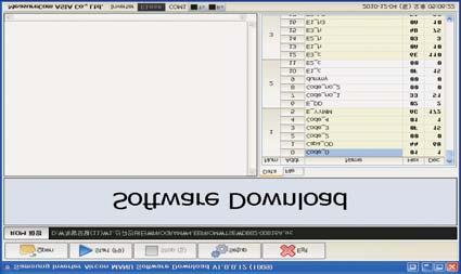
17

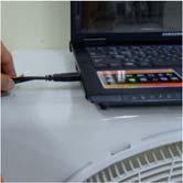
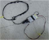
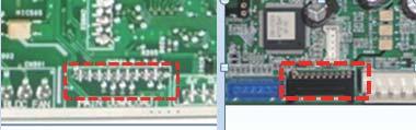
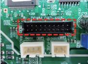
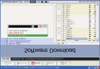
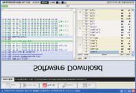
18 Download connector (0pin)
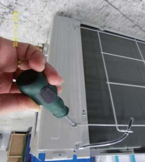
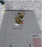
19 4. Disassembly and Reassembly Necessary Tools +SCREW DRIVER MONKEY SPANNER - SCREW DRIVER Samsung Electronics 4-


20 4-. Indoor Unit No Parts Procedure Remark PANEL-FRONT ) Stop the driving of air conditioner and shut off main power supply. 2) Detach FILTER PRE from the PANEL FRONT. 3) Cover Panel is assembled on bottom of indoor unit as shown in the figure. Remove the Cap Screw as shown on the right side and then remove the screw and separate the Cover Panel. 4-2 Samsung Electronics

 Separate the hook after pushing")
 6) Raise")

21 No Parts Procedure Remark 4) Cover Panel is fixed to body by Hook in center area and side area. Center area Side area Side area HOOK 9/2K 8/24/30K 5) Separate the hook after pushing both end of Cover Panel as shown in the figure. (Watch out for the damage of the hook) 6) Raise front part upward obliquely as shown in the figure and then remove the hooks. Samsung Electronics 4-3


 Hook (Center)")
22 No Parts Procedure Remark Caution: Assembly of Cover Panel after service end. - Reassembly is in the reverse order of the removal. - Piping and drain hose must be careful not to damage and Progress must be done with both hands. Hook (Side) Hook (Center) Screw Cap Screw 4-4 Samsung Electronics

 8) To detach the")


23 No Parts Procedure Remark 7) To detach the PANEL-FRONT from the main frame, unfasten 2 screws at the bottom. (use + Screw Driver) 8) To detach the COVER-PANEL from the main frame, loosen 4 HOOK Structures. When separate the hook : Use the (-) screw Driver. (-)Screw Driver Insert the hook and then pull the hook as shown on the right side. (Watch out for the damage of the hook) Samsung Electronics 4-5
 Remove the")

 Remove the WIFI KIT")


24 No Parts Procedure Remark 9) Remove the Panel Frame from the Main Frame as shown on the right side. 0) Remove the WIFI KIT connector. WIFI KIT connector is located of Panel Front. (For model with WIFI KIT) 4-6 Samsung Electronics


25 No Parts Procedure Remark 5 EVAPORATOR 9) Take off the CASE-CONTROL from the main frame after loosen the remaining connector. Caution: When you separate the connector, pull pressing the locking button. 3 TRAY DRAIN ) To detach TRAY-DRAIN from the main frame, pull the bottom of the TRAY-DRAIN towards you. 4-8 Samsung Electronics
 Detach the HOLDER PIPE.")
 3)")
 4) To detach")

26 No Parts Procedure Remark 4 Evaporator ) Detach the HOLDER PIPE. 2) Unfasten the screw at the left side. (use + Screw Driver) 3) Unfasten the screw at the right side. (use + Screw Driver) 4) To detach Evaporator from the main frame, pull the bottom of the Evaporator towards you. Samsung Electronics 4-9
")
 2)")
 Unfasten the screw a")
 4) Pull")
27 No Parts Procedure Remark 5 FAN MOTOR & CROSS FAN ) Unfasten the screw. (use + Screw Driver) 2) Detach the FAN Motor case. 3) Unfasten the screw a little. (use + Screw Driver) 4) Pull the CROSS-FAN to the left side. 4-0 Samsung Electronics


28 No Parts Procedure Remark 6 Assy SPI Lamp ) Remove the Assy SPI Lamp from the Back Body as shown on the right side. Caution : - Confirm Seal of backside necessarily after replace of Assy SPI Lamp. - Seal should be close adhesion to SPI Lamp. - Measure as shown on the right side since replace. (If the seal is not close adhesion perfectly : Defectiveness can happen) Samsung Electronics 4-


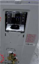
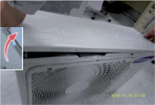
29 4-2 Outdoor Unit 3) Detach the Cabinet Upper like the picture. 4-2-

 on the left side (Use +Screw")
 4-2-2")
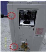
30 5) Loosen 2 screw(ccw) on the right side of Cabinet Front. (Use +Screw Driver) 6) Loosen 2 screw(ccw) on the left side of Cabinet Front. (Use +Screw Driver) 7) Loosen 3 screw(ccw) on the front side of Cabinet Front. (Use +Screw Driver) 4-2-2
31 8 3 9
32 4-2-4


33 ) Release Nut at Fan Boss 2) Release 3 screws st Motor Bracket. 3) Detach Motor Wire from the Assy Control Out
 N o Parts Procedure Rem ark CASE")


34 5. Disassembly WIFI 5- WIFI Case (AR09HSSDBWKNEU AR2HSSDBWKNEU) N o Parts Procedure Rem ark CASE Separate Case-WIFI Top from Case-WIFI Button 2 BUTTON Separate Case-WIFI Top from Case-WIFI Button Detach Assy Connector Wire from Case-WIFI Button 3 WIRE *Caution When you separate the connector, pull press -ing the locking button 4 PBA Separate PBA WIFI from Case-WIFI Button Samsung Electronics 5-

35 5-2 ASSY CONTROL IN AR09HSSDBWK/EU AR2HSSDBWK/EU No CODE DB H Description ASSY CONTROL IN Spec Q'TY DB C Aluminum SHEET 0x0xT0.07,AL SHEET 4 DB A CASE-CONTROL IN CASE-CONTROL IN DB A POWER WIRE T/B-main(power) DB A EARTH WIRE EARTH WIRE DB A TERMINAL BLOCK TERMINAL BLOCK DB62-656F SEAL CUTT PVC,BLACK,T,W54 DB62-680A SEAL CONTROL ASSY-LABEL FLOCKED,BLACK,T,W50,54 ASSY-LABEL DB A DB A COMMUNICATION WIRE T/B-main(485) DB A FUSE WIRE power-main(2v 5V) DB D Aluminum SHEET 22x22xT0.07,AL SHEET DB A ASSY-LABEL ASSY-LABEL DB A PLATE-CONTROL IN F0 DB A ASSY-LABEL ASSY-LABEL DB A SCREW M3,L25,ZPC(WHT),SWRCH8A DB6-0582A PLATE PLATE SCREW TH,M4,L0,ZPC(WHT),SWRCH8A SCREW M4,L2,ZPC(WHT),SWRCH8A 2 DB6-0587A HOLDER-WIRE CLAMP HOLDER-WIRE CLAMP DB A MAIN PBA STD4 DB A POWER PBA STDW DB7-5002A WIRE-SADDLE WIRE-SADDLE DB A ASSY CONNECTOR WIRE-DC power-main(30v 9V) DB A ASSY THERMISTOR IN sensor room 2evap DB93-422A ASSY CONNECTOR WIRE-DC FJM DB A ASSY CONNECTOR WIRE-DC main-power(smps IN) DB A ASSY CONNECTOR WIRE-DC Step-main(Left) Samsung Electronics

 DB93-4207A FUSE WIRE power-main(2v 5V) DB63-03553D DB68-33293A Aluminum SHEET ASSY-LABEL")
36 5-2 ASSY CONTROL IN (AR2HSSDRWKNER) No CODE DB K Description ASSY CONTROL IN Spec Q'TY DB C Aluminum SHEET 0x0xT0.07,AL SHEET 4 DB A DB A CASE-CONTROL IN POWER WIRE CASE-CONTROL IN T/B-main(power) DB A DB A DB62-656F EARTH WIRE TERMINAL BLOCK SEAL CUTT EARTH WIRE TERMINAL BLOCK PVC,BLACK,T,W54 DB62-680A DB A DB A SEAL CONTROL ASSY-LABEL COMMUNICATION WIRE T/B-main(485) DB A FUSE WIRE power-main(2v 5V) DB D DB A Aluminum SHEET ASSY-LABEL 22x22xT0.07,AL SHEET ASSY-LABEL DB A PLATE-CONTROL IN F0 DB A DB A ASSY-LABEL SCREW ASSY-LABEL M3,L25,ZPC(WHT),SWRCH8A DB6-0582A PLATE PLATE SCREW TH,M4,L0,ZPC(WHT),SWRCH8A DB6-0587A SCREW HOLDER-WIRE CLAMP M4,L2,ZPC(WHT),SWRCH8A HOLDER-WIRE CLAMP 2 DB A MAIN PBA STD4 DB A DB7-5002A POWER PBA WIRE-SADDLE STDW WIRE-SADDLE DB A ASSY CONNECTOR WIRE-DC power-main(30v 9V) DB A DB A ASSY THERMISTOR IN ASSY CONNECTOR WIRE-DC sensor room 2evap DB A ASSY CONNECTOR WIRE-DC FLOCKED,BLACK,T,W50,54 ASSY-LABEL Step-main(Left) main-power(smps IN) Samsung Electronics

37 5-3 Assy Control Out AR09HSSDBWKXEU AR2HSSDBWKXEU NAME No 5-4 CODE Q'ty unit GREASE-SILICON KG 2 SCREW-TAPPING PC 3 SCREW-TAPPING PC 4 HEAT SINK DB62-646A PC 5 SEAL CUTT DB62-656B 0 M 6 CABLE TIE DB B 2 PC 7 LABEL BAR CODE DB A PC 8 ASSY CASE CONTROL OUT DB N PC 9 ASSY COVER CONTROL-UP DB A PC 0 ASSY CASE CONTROL DB A PC ASSY-SCREW MACHINE DB A 4 PC 2 ASSY MODULE DB A PC 3 ASSY PCB MAIN DB A PC 4 ASSY CONNECTOR WIRE DB C PC 5 ASSY CONNECTOR WIRE DB E PC 6 ASSY CONNECTOR WIRE-POWER DB A PC 7 ASSY CONNECTOR WIRE-DC SIGNAL DB A PC 8 ASSY CONNECTOR WIRE-DC SIGNAL DB A PC Samsung Electronics
38 6. Electrical Parts List 6- INDOOR MAIN PCB (DB E) Parts Code Design Loc Parts Dsecription Quantity Q70 TR-POWER VA7 VARISTOR XC7 C-FILM,LEAD-PPF XC72 C-FILM,LEAD-PPF BZ6 BUZZER-PIEZO CN2 HEADER-BOARD TO CABLE CN75 HEADER-BOARD TO CABLE CN72 HEADER-BOARD TO CABLE CN3 HEADER-BOARD TO CABLE CN7 HEADER-BOARD TO CABLE CN9 HEADER-BOARD TO CABLE CN32 HEADER-BOARD TO CABLE CN43 HEADER-BOARD TO CABLE CN63 HEADER-BOARD TO CABLE CN62 HEADER-BOARD TO CABLE CN5 HEADER-BOARD TO CABLE DB A FT7 COIL CHOKE DB A VA7- CAP DB A LABEL BAR CODE LABEL BAR CODE DB A ASSY PCB AUTO Q80 TR-SMALL SIGNAL PTC2 THERMISTOR-PTC F70 FUSE-ETC CN76 HEADER-BOARD TO CABLE CN8 HEADER-BOARD TO CABLE CN77 CONNECTOR-HEADER CN6 HEADER-BOARD TO CABLE DB A ASSY PCB SMD D70 DIODE-RECTIFIER CD8 DIODE-TVS CD82 DIODE-TVS CD83 DIODE-TVS Q702 TR-SMALL SIGNAL Q60 TR-DIGITAL Q802 TR-DIGITAL IC05 TR-ARRAY IC06 TR-ARRAY PC03 PHOTO-COUPLER PC04 PHOTO-COUPLER PC05 PHOTO-COUPLER IC08 IC-CMOS LOGIC IC07 IC-BUS TRANSCEIVER IC IC-VOLTAGE COMP IC03 IC-VOL. DETECTOR IC02 IC-POSI.FIXED REG R850 R-CHIP R85 R-CHIP R73 R-CHIP R77 R-CHIP Samsung Electronics 6-
39 INDOOR MAIN PCB (DB A) cont R60 R-CHIP R602 R-CHIP R76 R-CHIP R703 R-CHIP R706 R-CHIP R805 R-CHIP R85 R-CHIP R707 R-CHIP R708 R-CHIP R70 R-CHIP R704 R-CHIP R705 R-CHIP R723 R-CHIP R80 R-CHIP R802 R-CHIP R803 R-CHIP R804 R-CHIP R86 R-CHIP R825 R-CHIP R75 R-CHIP R508 R-CHIP R55 R-CHIP R56 R-CHIP R57 R-CHIP R58 R-CHIP R59 R-CHIP R520 R-CHIP R539 R-CHIP R542 R-CHIP R809 R-CHIP R538 R-CHIP R545 R-CHIP R806 R-CHIP R90 R-CHIP R5 R-CHIP R52 R-CHIP R53 R-CHIP R502 R-CHIP R503 R-CHIP R504 R-CHIP R505 R-CHIP R506 R-CHIP R507 R-CHIP R50 R-CHIP R52 R-CHIP R522 R-CHIP R523 R-CHIP R524 R-CHIP R525 R-CHIP R526 R-CHIP 6-2 Samsung Electronics
40 INDOOR MAIN PCB (DB A) R527 R-CHIP R528 R-CHIP R529 R-CHIP R530 R-CHIP R53 R-CHIP R532 R-CHIP R533 R-CHIP R534 R-CHIP R543 R-CHIP R544 R-CHIP R807 R-CHIP R808 R-CHIP R80 R-CHIP R824 R-CHIP R903 R-CHIP R904 R-CHIP R902 R-CHIP R820 R-CHIP R82 R-CHIP R83 R-CHIP R833 R-CHIP R835 R-CHIP R837 R-CHIP R839 R-CHIP R843 R-CHIP R702 R-CHIP R5 R-CHIP R72 R-CHIP R709 R-CHIP R2 R-CHIP R3 R-CHIP R4 R-CHIP R7 R-CHIP R74 R-CHIP R404 R-CHIP R405 R-CHIP R406 R-CHIP R40 R-CHIP R8 R-CHIP R68 R-CHIP R40 R-CHIP R402 R-CHIP R403 R-CHIP R30 R-CHIP R302 R-CHIP R303 R-CHIP C705 C-CER,CHIP C80 C-CER,CHIP C508 C-CER,CHIP C56 C-CER,CHIP 6-4 Samsung Electronics
41 INDOOR MAIN PCB (DB A) ``cont C520 C-CER,CHIP C90 C-CER,CHIP C7 C-CER,CHIP C75 C-CER,CHIP C59 C-CER,CHIP C40 C-CER,CHIP C402 C-CER,CHIP C403 C-CER,CHIP C5 C-CER,CHIP C53 C-CER,CHIP C54 C-CER,CHIP C57 C-CER,CHIP C522 C-CER,CHIP C529 C-CER,CHIP C530 C-CER,CHIP C53 C-CER,CHIP C533 C-CER,CHIP C702 C-CER,CHIP C704 C-CER,CHIP C70 C-CER,CHIP C72 C-CER,CHIP C73 C-CER,CHIP C802 C-CER,CHIP C803 C-CER,CHIP C805 C-CER,CHIP C806 C-CER,CHIP C807 C-CER,CHIP C809 C-CER,CHIP C707 C-CER,CHIP C708 C-CER,CHIP C509 C-CER,CHIP C52 C-CER,CHIP C55 C-CER,CHIP C58 C-CER,CHIP C52 C-CER,CHIP C523 C-CER,CHIP C526 C-CER,CHIP C528 C-CER,CHIP C55 C-CER,CHIP C552 C-CER,CHIP C804 C-CER,CHIP C808 C-CER,CHIP C706 C-AL,SMD C70 C-AL,SMD C703 C-AL,SMD X50 RESONATOR-CERAMIC DB4-022A PCB MAIN PCB MAIN DB9-0550A IC04 ASSY MICOM IC-MICROCONTROLLER DB A ASSY-LABEL MICOM ASSY-LABEL MICOM 6-4 Samsung Electronics
42 6-2 INDOOR SUB PBA(DB A) Parts Code Design Loc Parts Description Quantity RM0 MODULE REMOCON CN0 HEADER-BOARD TO CABLE DB A COVER-SENSOR COVER-SENSOR DB A - ASSY PCB SMD CD0 DIODE-TVS J R-CHIP R0 R-CHIP C03 C-CER,CHIP C02 C-CER,CHIP DB A - ASSY PCB AUTO C0 C-AL SW0 SWITCH-TACT DB4-0222A PCB SUB PCB SUB Samsung Electronics 6-5
43 OUTDOOR MAIN PBA(DB A) - (cont.) modelcode Design Loc Parts Description Quantity SOLDER-BAR SOLDER-BAR SOLDER-WIRE SOLDER-WIRE FLUX FLUX SOLVENT SOLVENT PTC020 THERMISTOR-PTC VA002 VARISTOR VA003 VARISTOR VA00 VARISTOR VA40 VARISTOR C425 C-CERAMIC,DISC C004 C-CERAMIC,DISC C005 C-CERAMIC,DISC C02 C-CERAMIC,DISC C03 C-CERAMIC,DISC C00 C-FILM,LEAD-PPF C006 C-FILM,LEAD-PPF C42 C-FILM,LEAD-PPF CE0 C-AL CE02 C-AL CE03 C-AL RY022 RELAY-MINIATURE RY030 RELAY-MINIATURE RY02 RELAY-POWER CN30 HEADER-BOARD TO CABLE CN030 HEADER-BOARD TO CABLE CN90 HEADER-BOARD TO CABLE CN55 HEADER-BOARD TO CABLE CN20 HEADER-BOARD TO CABLE CN50 HEADER-BOARD TO CABLE CN25 HEADER-BOARD TO CABLE CN402 HEADER-BOARD TO CABLE CN40 HEADER-BOARD TO CABLE CN50 HEADER-BOARD TO BOARD CN003 CONNECTOR-TERMINAL CN00 CONNECTOR-TERMINAL CN002 CONNECTOR-TERMINAL PFC050 POWER MODULE IPM400 POWER MODULE DB A FT00 COIL CHOKE DB A SUPPORT-IC SUPPORT-IC DB6-0596A SUPPORT-PCB SUPPORT-PCB DB A - LABEL BAR CODE DB A ASSY PCB AUTO Q5 TR-DIGITAL C90 C-CERAMIC,DISC CE62 C-AL CE63 C-AL CE5 C-AL CE902 C-AL 6-2 Samsung Electronics
44 OUTDOOR MAIN PBA(DB A) - (cont.) CE52 C-AL CE90 C-AL F00 FUSE-AXIAL LEAD CN203 HEADER-BOARD TO CABLE CN202 HEADER-BOARD TO CABLE CN52 HEADER-BOARD TO CABLE CN5 HEADER-BOARD TO CABLE CN70 CONNECTOR-HEADER CN204 HEADER-BOARD TO CABLE DSA00 SURGE ABSORBER DB A ASSY PCB SMD SOLDER-CREAM SOLDER-CREAM D020 DIODE-SWITCHING D02 DIODE-SWITCHING D030 DIODE-SWITCHING D52 DIODE-SWITCHING D53 DIODE-SWITCHING D454 DIODE-SWITCHING D500 DIODE-SWITCHING D50 DIODE-SWITCHING D502 DIODE-SWITCHING D503 DIODE-SWITCHING D504 DIODE-SWITCHING D505 DIODE-SWITCHING D507 DIODE-SWITCHING D508 DIODE-SWITCHING D904 DIODE-SWITCHING D905 DIODE-SWITCHING D903 DIODE-RECTIFIER ZD40 DIODE-ZENER ZD420 DIODE-ZENER D49 DIODE-SCHOTTKY D492 DIODE-SCHOTTKY TD30 DIODE-TVS TD302 DIODE-TVS TD303 DIODE-TVS Q55 TR-SMALL SIGNAL Q35 TR-DIGITAL Q352 TR-DIGITAL Q90 TR-DIGITAL Q903 TR-DIGITAL Q902 TR-DIGITAL IC06 TR-ARRAY IC70 TR-ARRAY IC702 TR-ARRAY LED80 LED LED803 LED LED55 LED LED802 LED PC5 PHOTO-COUPLER 6-2 Samsung Electronics
45 OUTDOOR MAIN PBA(DB A) (cont.) PC35 PHOTO-COUPLER PC352 PHOTO-COUPLER IC302 IC-CMOS LOGIC IC30 IC-BUS TRANSCEIVER IC45 IC-OP AMP IC54 IC-POSI.FIXED REG IC55 IC-POSI.FIXED REG IC502 IC-VOL. DETECTOR R424 R-CHIP R309 R-CHIP R52 R-CHIP R20 R-CHIP R23 R-CHIP R233 R-CHIP R234 R-CHIP R40 R-CHIP R402 R-CHIP R403 R-CHIP R404 R-CHIP R405 R-CHIP R406 R-CHIP R407 R-CHIP R420 R-CHIP R422 R-CHIP R56 R-CHIP R59 R-CHIP R562 R-CHIP R53 R-CHIP R255 R-CHIP R256 R-CHIP R257 R-CHIP R258 R-CHIP R352 R-CHIP R353 R-CHIP R52 R-CHIP R567 R-CHIP R904 R-CHIP R303 R-CHIP R307 R-CHIP R308 R-CHIP R35 R-CHIP R354 R-CHIP R503 R-CHIP R504 R-CHIP R505 R-CHIP R508 R-CHIP R509 R-CHIP R55 R-CHIP R529 R-CHIP R530 R-CHIP 6-2 Samsung Electronics
46 OUTDOOR MAIN PBA(DB A) - (cont.) R556 R-CHIP R557 R-CHIP R558 R-CHIP R560 R-CHIP R563 R-CHIP R522 R-CHIP R42 R-CHIP R2 R-CHIP R22 R-CHIP R24 R-CHIP R25 R-CHIP R26 R-CHIP R27 R-CHIP R28 R-CHIP R29 R-CHIP R220 R-CHIP R408 R-CHIP R50 R-CHIP R506 R-CHIP R507 R-CHIP R50 R-CHIP R5 R-CHIP R57 R-CHIP R58 R-CHIP R520 R-CHIP R52 R-CHIP R523 R-CHIP R524 R-CHIP R525 R-CHIP R526 R-CHIP R527 R-CHIP R534 R-CHIP R535 R-CHIP R536 R-CHIP R903 R-CHIP R30 R-CHIP R302 R-CHIP R304 R-CHIP R305 R-CHIP R528 R-CHIP R532 R-CHIP R533 R-CHIP R55 R-CHIP R552 R-CHIP R553 R-CHIP R554 R-CHIP R555 R-CHIP R559 R-CHIP R565 R-CHIP R53 R-CHIP 6-2 Samsung Electronics
47 OUTDOOR MAIN PBA(DB A) - (cont.) R306 R-CHIP R564 R-CHIP R202 R-CHIP R205 R-CHIP R207 R-CHIP R22 R-CHIP R222 R-CHIP R223 R-CHIP R224 R-CHIP R225 R-CHIP R226 R-CHIP R227 R-CHIP R228 R-CHIP R229 R-CHIP R230 R-CHIP R23 R-CHIP R232 R-CHIP R203 R-CHIP R204 R-CHIP R206 R-CHIP R20 R-CHIP R49 R-CHIP R455 R-CHIP R457 R-CHIP R468 R-CHIP R90 R-CHIP R0 R-CHIP R05 R-CHIP R25 R-CHIP R253 R-CHIP R56 R-CHIP R492 R-CHIP R54 R-CHIP R55 R-CHIP R56 R-CHIP R57 R-CHIP R58 R-CHIP R252 R-CHIP R254 R-CHIP R469 R-CHIP R470 R-CHIP R47 R-CHIP R472 R-CHIP R473 R-CHIP R474 R-CHIP R475 R-CHIP R454 R-CHIP R459 R-CHIP R466 R-CHIP R476 R-CHIP 6-2 Samsung Electronics
48 OUTDOOR MAIN PBA(DB A) - (cont.) R477 R-CHIP R80 R-CHIP R802 R-CHIP R803 R-CHIP R02 R-CHIP R03 R-CHIP R04 R-CHIP R06 R-CHIP R07 R-CHIP R08 R-CHIP R478 R-CHIP R902 R-CHIP R409 R-CHIP R423 R-CHIP R427 R-CHIP R40 R-CHIP R4 R-CHIP R42 R-CHIP R425 R-CHIP R426 R-CHIP C42 C-CER,CHIP C222 C-CER,CHIP C223 C-CER,CHIP C224 C-CER,CHIP C225 C-CER,CHIP C30 C-CER,CHIP C35 C-CER,CHIP C352 C-CER,CHIP C422 C-CER,CHIP C423 C-CER,CHIP C404 C-CER,CHIP C405 C-CER,CHIP C406 C-CER,CHIP C408 C-CER,CHIP C409 C-CER,CHIP C40 C-CER,CHIP C4 C-CER,CHIP C50 C-CER,CHIP C504 C-CER,CHIP C505 C-CER,CHIP C506 C-CER,CHIP C507 C-CER,CHIP C508 C-CER,CHIP C50 C-CER,CHIP C52 C-CER,CHIP C523 C-CER,CHIP C904 C-CER,CHIP C455 C-CER,CHIP C458 C-CER,CHIP C453 C-CER,CHIP 6-2 Samsung Electronics
49 OUTDOOR MAIN PBA(DB A) - (cont.) C454 C-CER,CHIP C459 C-CER,CHIP C55 C-CER,CHIP C56 C-CER,CHIP C57 C-CER,CHIP C58 C-CER,CHIP C59 C-CER,CHIP C524 C-CER,CHIP C06 C-CER,CHIP C5 C-CER,CHIP C52 C-CER,CHIP C53 C-CER,CHIP C54 C-CER,CHIP C62 C-CER,CHIP C63 C-CER,CHIP C220 C-CER,CHIP C22 C-CER,CHIP C25 C-CER,CHIP C252 C-CER,CHIP C253 C-CER,CHIP C254 C-CER,CHIP C302 C-CER,CHIP C303 C-CER,CHIP C304 C-CER,CHIP C305 C-CER,CHIP C306 C-CER,CHIP C307 C-CER,CHIP C40 C-CER,CHIP C402 C-CER,CHIP C403 C-CER,CHIP C407 C-CER,CHIP C420 C-CER,CHIP C424 C-CER,CHIP C460 C-CER,CHIP C503 C-CER,CHIP C509 C-CER,CHIP C5 C-CER,CHIP C54 C-CER,CHIP C520 C-CER,CHIP C52 C-CER,CHIP C525 C-CER,CHIP C526 C-CER,CHIP C527 C-CER,CHIP C70 C-CER,CHIP C702 C-CER,CHIP C703 C-CER,CHIP C704 C-CER,CHIP C903 C-CER,CHIP C20 C-CER,CHIP C203 C-CER,CHIP 6-2 Samsung Electronics
50 OUTDOOR MAIN PBA(DB A) - (cont.) C204 C-CER,CHIP C206 C-CER,CHIP C207 C-CER,CHIP C208 C-CER,CHIP C20 C-CER,CHIP C2 C-CER,CHIP C22 C-CER,CHIP C522 C-CER,CHIP C902 C-CER,CHIP C202 C-CER,CHIP C205 C-CER,CHIP C209 C-CER,CHIP C23 C-CER,CHIP C24 C-CER,CHIP C226 C-CER,CHIP C227 C-CER,CHIP C228 C-CER,CHIP C229 C-CER,CHIP CE45 C-AL,SMD CE53 C-AL,SMD CE404 C-AL,SMD CE420 C-AL,SMD CE40 C-AL,SMD CE402 C-AL,SMD CE403 C-AL,SMD X20 RESONATOR-CERAMIC X50 RESONATOR-CERAMIC DB4-0227A PCB MAIN PCB MAIN DB9-057A IC50 ASSY MICOM IC-MICROCONTROLLER DB A ASSY-LABEL MICOM ASSY-LABEL MICOM DB9-0534A IC20 ASSY MICOM DB A - IC MICOM 6-2 Samsung Electronics
51 7. Wiring Diagram 7- Indoor Unit Samsung Electronics 7-
52 7-2 Outdoor Unit 7-2 Samsung Electronics

53 8- Indoor PCB CN2 CN8 CN6 CN63 CN62 CN43 CN76 CN32 CN9 CN77 CN3 CN5 CN72 CN75 CN7 ① CN6/CN62/CN63 STEP MOTOR ② CN7 - POWER IN ③ CN8 - SPI ④ CN5 - WI-FI MODULE #,#3 : AC220~240V #: SPI SIGNAL #: DC 2V #2 : N.C #3 : DC 2V # #2 #3 #4 #5 #6 ⑥ CN43 - TEMPERATURE SENSOR ⑦ CN2 - COMMUNICATION ⑧ CN72 - BLDC FAN MOTOR #,#2 : 485 COMM SIGNAL # #2 #3 #4 #5 #6 #2~#5 :STEP MOTOR SIGNAL ⑤ CN5 - DISPLAY #~#,#4,#7~#20 : MICOM DOWN #,#2 : ROOM SENSOR #2, #3, #5, #6 : N.C #3,#4 : EVA MID SENSOR #5,#6 : EVA IN SENSOR ⑨ CN32 - FJM/NASA CN75 - SMPS POWER IN #~#7, #~ #4 : FJM/NASA SIGNAL#,#3 : AC220~240V CN76 - SMPS DC OUT (2V/GND/5V) : : : : : : : : : : : : WIFI UART SIGNAL WIFI UART SIGNAL2 WIFI RESET SIGNAL GND DC 2V N.C DC 30~340V N.C AGND DC 5V FAN RPM FAN FEEDBACK CN77 - SMPS DC OUT (9V/GND/30V) # : DC 5V # : DC 30V~340V #9 : GND #2 : GND #2,#3 : N.C #0 : DC 2V #3 : DC 2V #4 : DC 9V~27V #8 : DC 5V #2 : N.C #5 : AGND CN3 - DOWNLOAD DOWNLOAD Samsung Electronics 8-

54 8-2 Outdoor PCB ① CN5 - SMPS INV ② CN204 - DRED ③ CN20- DOWNLOAD-MAIN ④ CN25 - SENSOR # : 5V #2 : GND #3 : ENABLE # #2 #3 #4 #5 # ~ #20 : DOWNLAOD #,#2 : OUT SENSOR #3,#4 : DISCHARGE SENSOR #5,#6 : COND SENSOR ⑤ CN50 - EEPROM ⑥ CN70 - EEV-A ⑦ CN52 - SMPS MAIN ⑧ CN30 - COMMUNICATION # #3 #4 #5 #6 #7 #~#4 : EEV SIGNAL #5 : 2V # : 2V #2 : GND #3 : 5V # : F #2 : F2 : : : : : : GND 5V EEP CS EEP_SO/MICOM RX EEP_SI_MICOM_TX EEP CLK ⑨ CN90 - FAN # #2 #3 #4 #5 #6 : : : : : : DC 30~340V N.C AGND DC 5V FAN RPM FAN FEEDBACK CN002 - POWER-L # : L 8-2 : DRED : DRED2 : DRED3 : GND : 5V CN40- REACTOR # : REACTOR #2 : REACTOR2 CN003 - EARTH # : EARTH CN030-4WAY #,#3 : AC220~240V CN50 - SMPS AC #,#3 : AC220~240V CN00 - POWER-N # : N CN402 - COMP # : W #2 : V #3 : U Samsung Electronics


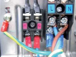
55 8-3 Wire connecting the indoor unit terminal blocks. Terminal press of Ring terminal shall be set facing up before connecting wire. Is inverted 2. There shall be no empty space between Ring terminal and Screw after Clamp. If not, there exists a possibility of fire which can be caused by electric heat in the connecting part., 8-3 Terminalhasbeencut. : Good Bad : Ring terminal is connected reversely Bad : Not clamped Screw Bad : In the gap between Ring terminal & Screw Bad : Unused Ring Terminal Samsung Electronics


56 9. Operating Instructions 9- Name of Each Part 9-- Indoor Unit The design and shape are subject to change according to the model. Main Parts Room temperature sensor Air intake Wi-Fi module SPi Lamp (up and down) (left and right) Display Temperature indicator / Filter Reset indicator Defrost indicator Power consumption indicator / Auto clean indicator Power button/ Remote controller receiver W i-fi indicator Timer/ Auto cleanindicator Samsung Electronics 9-
57 9-2 Wireless Remote Control-Buttons and Display Remote controller display Set the SPi Turbo / Soft Select Ultra turbo function or Soft function ECO Run reduces energy usage while operating in cool/heat mode. Temp + - Increase/Decrease the temperature by C. Auto Clean Auto clean function Dry inside of the indoor unit to get rid of odor. d'light Cool On Timer Set the On Timer on. Filter Reset Reset the Filter Clean reminder SPi Usage Display the amount of power consumption for few seconds on the indoor unit display: To silence the beep sound when pressing the button. Time set Set the current time Power Mode Set one of the 5 operating modes (see pages 5~6 for instructions). Quiet Reduce noise generated from an indoor unit during operation. Vertical air swing automatically up and down. Fan such as Auto/Low/Medium/High/Turbo. Horizontal air swing movement automatically left and right. Set the mode on. Set/Cancel Set/Cancel the timer/ mode. SMART Air conditioner Network. 2 nd F Switch the function of the button on the remote controller. 9-2 Samsung Electronics
58 0. Troubleshooting 0- Items to be checked first. The input voltage should be rating voltage 0% range. The air conditioner may not operate properly if the voltage is out of this range. 2. Is the line cable linking the indoor unit and the outdoor unit linked properly? The indoor unit and the outdoor unit shall be linked by 5 cables. Check the terminals if the indoor unit and outdoor unit are properly linked by the same number of cables. Otherwise the air conditioner may not operate properly. 3. When a problem occurs due to the contents illustrated in the table below it is a symptom not related to the malfunction of the air conditioner. Operation of air conditioner Explanation 2 The OPERATION indication LED(BLUE) blinks when a power plug of the indoor unit is plugged in for first time. In a COOL operation mode, the compressor does not operate at a room temperature higher than the setting temperature that the INDOOR FAN should operate. [ In case of heat pump model ] In a HEAT operation mode, the compressor does not operate at a room temperature lower than the setting temperature that indoor fan should operate. It indicates power is on. The LED stops blinking if the operation ON/OFF button on the remote control unit is pushed. In happens after a delay of 3 minutes when the compressor is reoperated. The same phenomenon occurs when a power is on. As a phenomenon that the compressor is reoperated after a delay of 3 minutes, the indoor fan is adjusted automatically with reference to a temperature of the air blew. 3 Fan speed setting is not allowed in DRY mode. The speed of the indoor fan is set to LL in DRY mode. Fan speed is selected automatically in AUTO mode Compressor stops operation intermittently in Dry mode. Timer LED(ORANGE) of the indoor unit lights up and the air conditioner does not operate. The compressor stops intermittently in a COOL mode or DRY mode, and fan speed of the indoor unit decreases. [In case of heat pump model] Compressor of the outdoor unit is operating although it is turned off in a HEAT mode. [In case of heat pump model] The compressor and indoor fan stop intermittenly in HEAT mode. [In case of heat pump model] Indoor fan and outdoor fan stop operation intermittently in a HEAT mode. Compressor operation is controlled automatically in DRY mode depending on the room temperature and humidity. Timer is being activated and the unit is in ready mode. The unit operates normally if the timer operation is cancelled. The compressor stops intermittently or the fan speed of the indoor unit decreases to prevent inside/outside air frozen depending on the inside/outside air temperature. When the unit is turned off while de-ice is activated, the compressor continus operation for up to 9 minutes(maximum) until the deice is completed. The compressor and indoor fan stop intermittently if room temperature exceeds a setting temperature in order to protect the compressor from overheated air in a HEAT mode. The compressor operates in a reverse cycle to remove exterior ice in a HEAT mode, and indoor fan and outdoor fan do not operate intermittently for within 20% of the total heater operation. Samsung Electronics 0-
59 0-2 Communication Error 0-2- Communication Error Indoor display 3-LED DISPLAY 7-SEG DISPLAY DESCRIPTION LED LED2 LED3 E0/E02 Communication error(indoor<->outdoor) Outdoor display min. Time out Comm. Abnormal Communication LED ON LED BLINKING LED OFF. Checklist : ) Is the cable between the indoor unit and outdoor unit connected correctly? 2) Isn't the power cable and communication cable cross? 2. Troubleshooting procedure Restart after power off. Is the communication error occurred again? Terminate the service. Is the connection of power cable and communication cable normal? Correct the wrong cable. Is the power is normal? (check the LED Lamp) Exchange the PBA of no power unit Exchange the indoor unit PBA. Is the communication error occurred again? Terminate the service. Exchange the outdoor unit PBA. 0-2 Samsung Electronics
60 0-2-2 Indoor temperature sensor Error Indoor display 7-SEG DISPLAY E2 DESCRIPTION Indoor room temp sensor error. Checklist : ) Is the indoor units temperature sensor connected correctly? 2) Is the sensor placed correctly? 3) Does the both terminal of sensor satisfy the resistance value in accordance with temperature? 2. Troubleshooting procedure Detach the assembled sensor from the PBA sensor connector and measure the sensor resistance with ohmmeter(tester) Is the sensor resistance value 0kohm±3% at the room temperature of 25 C Connect the sensor to PBA connector (6piin) supply power Is the connection and measure of the power voltage cable of #-#2 in and communication the connector cable normal? Ass'y Sensor Replace Sensor resistance value : 20 C- 2.09kohm 30 C - 8.3kohm 35 C kohm 40 C- 5.83kohm Below 0.5V or Over 4.5V? Exchange the indoor PBA Micom error or connector check Exchange the indoor PBA Samsung Electronics 0-3
61 0-2-3 Indoor Eva-in temperature sensor error Indoor display 3-LED DISPLAY 7-SEG DISPLAY DESCRIPTION LED LED2 LED3 E22,E23 Indoor MID, Indoor IN PIPE-TH sensor error LED ON LED BLINKING LED OFF. Checklist : ) Is the indoor units temperature sensor connected correctly? 2) Is the sensor placed correctly? 3) Does the both terminal of sensor satisfy the resistance value in accordance with temperature? 2. Troubleshooting procedure Detach the assembled sensor from the PBA sensor connector and measure the sensor resistance with ohmmeter(tester) Is the sensor resistance value #3-#4 and #5-#6 0kohm±3% at the room temperature of 25 Connect the sensor to PBA connector (6piin) supply power Is the connection and measure of power the voltage cable of #3-#4 and and communication #5-#6 in the connector cable normal? Sensor Replace Sensor resistance value : 20 C- 2.09kohm 30 C - 8.3kohm 35 C kohm 40 C- 5.83kohm Below 0.5V or Over 4.5V? Exchange the indoor PBA Micom error or connector check Exchange the indoor PBA 0-4 Samsung Electronics
62 0-2-4 When the Up/Down, Left/Right, Grill louver motor does not operate (Initial Diagnosis) (Not displayed). Checklist : ) Is the input power voltage normal? 2) Is the Up/Down louver motor properly connected with the connector? (CN6, CN62, CN63) 2. Troubleshooting procedure Unplug the power cord and plug it after 30seconds later. Is the lamp blinking? Check the as in the procedure. No power. Is the connected louver wire? Connect the wire PBA to louver motor Does operation start when swing button of the remote control unit pushed? Normal Is the voltage changeable at the pin#2~#5 of CN6, CN62, CN63 (louver connector)? Exchange the PBA Up/Down louver motor is faulty. Samsung Electronics 0-5
63 0-2-5 Indoor fan motor speed detecting error (BLDC fan) Indoor display 3-LED DISPLAY 7-SEG DISPLAY DESCRIPTION LED LED2 LED3 E54 Indoor fan error LED ON LED BLINKING LED OFF. Checklist : ) Is the indoor units fan motor properly connected with the connector(cn72)? 2) Is the AC voltage correct? 2. Troubleshooting procedure Restart after power off. Does the fan rotate? Power off and Separate the Fan motor wire from CN72 on Indoor PBA Reassemble the fan wire and input the power again Is there short among each pin #~#6 Exchange the Fan motor Is the fan error appeared again? Terminate the service Is the voltage of CN72 #-#3 over 250Vdc Follow the check procedure of Indoor unit power supply error check Is the voltage of CN72 #3-#5 and #3-#6 with in Vdc~5Vdc during the operation? Exchange the Indoor PBA PBA problem or Motor problem Change the PBA first and check the operation Exchange the Fan motor 0-6 Samsung Electronics
 Is the sensor connected correctly? 2) Is the sensor placed correctly?")
64 0-2-6 Outdoor temperature sensor error Indoor display 3-LED DISPLAY 7-SEG DISPLAY DESCRIPTION LED LED2 LED3 E22 Outdoor temperature sensor error Outdoor display Outdoor temperature sensor error LED ON LED BLINKING LED OFF. Checklist : ) Is the sensor connected correctly? 2) Is the sensor placed correctly? 3) Does the both terminal of sensor satisfy the resistance value in accordance with temperature? 4) Is the resistance value of sensor connection pull-up correct? 2. Troubleshooting procedure MODEL "A" "B" AR09HSSDBWKXEU CN25 CN25 #-#2 AR2HSSDBWKXEU CN25 CN25 #-#2 AR2HSSDRWKXER CN25 CN25 #-#2 Is the sensor connector("a") connected correctly in accordance with a color? Reconnect the sensor connector. Is the sensor resistance value "B" 0kohm±3% at the room temperature of 25 Connect the sensor to PBA connector supply Is the power connection and measure of power the voltage cable of and communication "B"in the connector cable normal? Sensor Replace Sensor resistance value : kohm kohm kohm kkohm Below 0.5Vdc or Over 4.5Vdc? Exchange the Outdoor PBA Micom error or connector check Exchange the Outdoor PBA Samsung Electronics 0-7
65 0-2-7 Outdoor Coil temperature sensor error Indoor display 3-LED DISPLAY 7-SEG DISPLAY DESCRIPTION LED LED2 LED3 E23 Outdoor Cond temperature sensor error Outdoor display Outdoor Cond temperature sensor error LED ON LED BLINKING LED OFF. Checklist : ) Is the sensor connected correctly? 2) Is the sensor placed correctly? 3) Does the both terminal of sensor satisfy the resistance value in accordance with temperature? 4) Is the resistance value of sensor connection pull-up correct? 2. Troubleshooting procedure Is the sensor connector("a") connected correctly in accordance with a color? MODEL "A" "B" AR09HSSDBWKXEU CN25 CN25 #5-#6 AR2HSSDBWKXEU CN25 CN25 #5-#6 AR2HSSDRWKXER CN25 CN25 #5-#6 Reconnect the sensor connector. Is the sensor resistance value "B" 0kohm±3% at the room temperature of 25 Connect the sensor to PBA connector supply power Is the and connection measure the of power voltage cable of "B"in the and communication connector cable normal? Sensor Replace Sensor resistance value : kohm kohm kohm kohm Below 0.5Vdc or Over 4.5Vdc? Exchange the Outdoor PBA Micom error or connector check Exchange the Outdoor PBA 0-8 Samsung Electronics
 Is the sensor connected correctly? 2) Is the sensor placed correctly?")
66 0-2-8 Outdoor Discharge temperature sensor error Indoor display 3-LED DISPLAY 7-SEG DISPLAY DESCRIPTION LED LED2 LED3 Outdoor Discharge temperature E25 sensor error Outdoor display Outdoor Discharge temperature sensor error LED ON LED BLINKING LED OFF. Checklist : ) Is the sensor connected correctly? 2) Is the sensor placed correctly? 3) Does the both terminal of sensor satisfy the resistance value in accordance with temperature? 4) Is the resistance value of sensor connection pull-up correct? MODEL "A" "B" AR09HSSDBWKXEU CN25 CN25 #3-#4 2. Troubleshooting procedure AR2HSSDBWKXEU CN25 CN25 #3-#4 AR2HSSDRWKXER CN25 CN25 #3-#4 Is the sensor connector("a") connected correctly in accordance with a color? Reconnect the sensor connector. Is the sensor resistance value "B" 200kohm±3% at the room temperature of 25 Connect the sensor to PBA connector supply power Is the and connection measure the of power voltage cable of "B"in the and communication connector cable normal? Sensor Replace Sensor resistance value : kohm 30-66ohm 35-38ohm 40-5kohm Below 0.5Vdc or Over 4.5Vdc? Exchange the Outdoor PBA Micom error or connector check Exchange the Outdoor PBA Samsung Electronics 0-9
67 0-2-9 Outdoor Discharge over temperature error Indoor display 3-LED DISPLAY 7-SEG DISPLAY DESCRIPTION LED LED2 LED3 E46 Outdoor Discharge over temperature error Outdoor display Outdoor Discharge over temperature error LED ON LED BLINKING LED OFF. Checklist : ) Check the discharge temperature in the outdoor unit 2) Check the compressor locking or gas leak 3) Download the EEPROM data 2. Troubleshooting procedure Restart after power off. after 30min ~ Hr Is the discharge over temperature sensor error appeared again? Terminate the service The condition is too poor for air conditioner to operate. Wait until discharge temperature is decreased Restart after power off Is the discharge over temperature sensor error appeared again? Terminate the service Download the EEPROM data Is the discharge over temperature sensor error appeared again? Terminate the service Exchange the Outdoor PBA Exchanged the Compressor 0-0 Samsung Electronics
68 0-2-0 Outdoor Fan motor error Indoor display 3-LED DISPLAY 7-SEG DISPLAY DESCRIPTION LED LED2 LED3 E458 O utdoorfan error Outdoor display LED ON LED BLINKING LED OFF Outdoor fan error. Checklist : ) Are the input power voltage and the power connection correct? 2) Is the motor wire connected to the outdoor PBA correctly? 3) Is there no assembly error or non-assembly in the terminal of motor wire connector? 4) Is there no obstacle at the surrounding of motor and propeller? 2. Troubleshooting procedure Restart after power off. MODEL AR09HSSDBWKXEU AR2HSSDBWKXEU AR2HSSDRWKXER "A" CN90 CN90 CN90 Does the fan rotate? Power off and Separate the Fan motor wire from "A" on Outdoor PBA Reassemble the fan wire and input the power again Is there short among each pin #~#6 Exchange the Fan motor Is the fan error appeared again? Terminate the service Is the voltage of "A" #-#3 over 250Vdc Follow the check procedure of outdoor unit power supply error check Is the voltage of "A" #3-#5 and #3-#6 with in Vdc~5Vdc during the operation? Exchange the Outdoor PBA PBA problem or Motor problem Change the PBA first and check the operation Exchange the Fan motor Samsung Electronics 0-
69 0-2- Compressor starting error Indoor display 3-LED DISPLAY 7-SEG DISPLAY DESCRIPTION LED LED2 LED3 E46 Comp starting error Outdoor display Comp starting error LED ON LED BLINKING LED OFF. Checklist : ) Is the connection of cable for the compressor? 2) Is the compressor wire is connected clockwise? U(RED)-V(BLU)-W(YEL) 3) Is the interphase resistance of compressor normal? 2. Troubleshooting procedure Restart after power off. Is the restart error occurred again? Terminate the service Is the connection of compressor wire is normal? Connect the comp wire normally Download the EEPROM data Is the restart error occurred again? Terminate the service Is the compressor body and interphase resistance insulated? Exchange the Outdoor PBA Exchange the compressor 0-2 Samsung Electronics
70 0-2-2 Compressor wire missing error/rotation error Indoor display 3-LED DISPLAY 7-SEG DISPLAY DESCRIPTION LED LED2 LED3 Compressor wire missing E467 errorr/rotation error Outdoor display Compressor wire missing error/rotation error LED ON LED BLINKING LED OFF. Checklist : ) Is the connection of cable for the compressor? 2) Is the compressor wire is connected clockwise? U(RED)-V(BLU)-W(YEL) 3) Is the interphase resistance of compressor normal? 2. Troubleshooting procedure Restart after power off. Is the restart error occurred again? Terminate the service Is the connection of compressor wire is normal? (PBA and Compressor) Connect the comp wire normally Is the restart error occurred again? Terminate the service Is the compressor body and interphase resistance insulated? Exchange the Outdoor PBA Exchange the compressor Samsung Electronics 0-3
71 0-2-3 O.C(Over Current) error Indoor display 3-LED DISPLAY 7-SEG DISPLAY DESCRIPTION LED LED2 LED3 E464 IPM Over Current(O.C) Error Outdoor display IPM Over Current(O.C) Error LED ON LED BLINKING LED OFF. Checklist : ) Is the IPM Shunt resistance value correct? Check the resistor is opened 2) Is the condition of surrounding temperature abnormal overload? 3) Is there any problem as like the temperature sensor separation or measurement value error? 4) Is the interphase resistance of compressor normal? 2. Troubleshooting procedure Restart after power off. Is the O.C error occurred? Terminate the service Is the connection of compressor wire is normal? Connect the comp wire normally Is the O.C error occurred again? Terminate the service Is the condition of indoor/outdoor temperature normal load? Restart after returning to the normal load Is the O.C error occurred again? Terminate the service 0-4 Samsung Electronics
72 Is the position of temperature sensor and sensing value normal? Correct the sensor position or exchange the sensor Is the compressor body and interphase resistance insulated? Exchange the Outdoor PBA Exchange the compressor Samsung Electronics 0-5
73 0-2-4 DC_link voltage sensor error Indoor display 3-LED DISPLAY 7-SEG DISPLAY DESCRIPTION LED LED2 LED3 E469 DC_link voltage sensor error Outdoor display DC_link voltage sensor error LED ON LED BLINKING LED OFF. Checklist : ) Is the input voltage of outdoor terminal block is normal? 2) Is the reactor wire connected? 3) Is the DC_link capacitor("a") assembled in accordance the specification? (Outdoor PBA) 4) Is the DC_link resistor("b") value is normal? (Outdoor PBA) 2. Troubleshooting procedure M O D EL "A" "B" AR09HSSDBWKXEU CE0,CE02,CE03 R40,R4,R42 AR2HSSDBWKNEU CE0,CE02,CE03 R40,R4,R42 AR2HSSDRWKNER CE0,CE02,CE03 R40,R4,R42 Is the connected of reactor wire? (PBA-Reactor) Connect the reactor wire Restart after power off. Start the operation (cooling mode or heating mode) Is the DC_link voltage ("A") is normal in operation mode? Normal range(280vdc~320vdc) Check the power input Is the DC_link sensing voltage("b") is normal in operation mode? Normal range (0.2Vdc~4.8Vdc) Exchange the Outdoor PBA Is the reactor insulation damaged? Exchange the Outdoor PBA Exchange the Reactor 0-6 Samsung Electronics
74 0-2-5 DC_link voltage sensor error Indoor display 3-LED DISPLAY 7-SEG DISPLAY DESCRIPTION LED LED2 LED3 E488 AC Input Voltage Sensor Error Outdoor display AC Input Voltage Sensor Error LED ON LED BLINKING LED OFF. Checklist : ) Is the input voltage of outdoor terminal block is normal? 2) Is the reactor wire connected? 3) Is the PFC resistor("a") value is normal? (Outdoor PBA) 2. Troubleshooting procedure MODEL "A" "B" AR09HSSDBWKXEU R05,R06,R07,R08 R05 AR2HSSDBWKXEU R05,R06,R07,R08 R05 AR2HSSDRWKXER R05,R06,R07,R08 R05 Is the connected of reactor wire? (PBA-Reactor) Connect the reactor wire Restart after power off. Start the operation (cooling mode or heating mode) Is the DC_link sensing voltage("b") is normal in operation mode? Normal range (0.2Vdc~4.8Vdc) Exchange the Outdoor PBA Is the reactor insulation damaged? Exchange the Outdoor PBA Exchange the Reactor Samsung Electronics 0-7
75 0-2-6 DC_link voltage under/over error, H/W DC-link Over voltage protection error/pfc over load Indoor display 3-LED DISPLAY 7-SEG DISPLAY DESCRIPTION LED LED2 LED3 E466 DC-Link voltage under/over error Outdoor display LED ON LED BLINKING LED OFF E483 E484 Over Voltage Protection Error PFC over ol ad DC-Link voltage under/over error PFC over load Over Voltage Protection Erro. Checklist : ) Is the input voltage of outdoor terminal block is normal? 2) Is the input voltage is higher than 300Vac? 3) Is the reactor wire connected? 4) Is the DC_link capacitor(a") assembled in accordance the specification? (Outdoor PBA) 5) Is the DC_link resistor("b") value is normal? (Outdoor PBA) M O D EL "A" 6) Is the PFC resistor("c") value is normal? (Outdoor PBA) 2. Troubleshooting procedure "B" AR09HSSDBWKXER CE0,CE02,CE03 R0,R02,R03,R04 AR2HSSDBWKXEU CE0,CE02,CE03 R0,R02,R03,R04 AR2HSSDRWKXER CE0,CE02,CE03 R0,R02,R03,R04 M O D EL "C" "D " AR09HSSDBXEUEU R05,R06,R07,R08 R0,R05 AR2HSSDBWKXEU R05,R06,R07,R08 R0,R05 AR2HSSDRWKXER R05,R06,R07,R08 R0,R05 Is the connected of reactor wire? (PBA-Reactor) Connect the reactor wire Restart after power off. Is the the input voltage is nomal? Normal range(80vac ~ 270Vac) Check the input power in the powercord. Restart after power off. Start the operation (cooling mode or heating mode) Is the DC_link voltage ("A") is normal in operation mode? Normal range(280vdc~320vdc) Check the input power 0-8 Samsung Electronics
76 Is the DC_link sensing voltage("d")is normal in operation mode? Normal range (0.2Vdc~4.0Vdc) Exchange the Outdoor PBA Is the reactor insulation damaged? Exchange the Outdoor PBA Exchange the Reactor Samsung Electronics 0-9
77 0-2-7 I_trip error, PFC over current Indoor display 3-LED DISPLAY 7-SEG DISPLAY DESCRIPTION LED LED2 LED3 E462 AC Input I_Limit Trip Error Outdoor display LED ON LED BLINKING LED OFF AC Input I_Limit Trip Error. Checklist : ) Is the PFC Shunt("A") resistance value correct? Check the resistor is opened 2) Is the condition of surrounding temperature abnormal overload? 3) Is there any problem as like the temperature sensor separation or measurement value error? 4) Is the interphase resistance of compressor normal? 2. Troubleshooting procedure Restart after power off. MODEL AR09HSSDBWK/EU AR2HSSDBWK/EU AR2HSSDRWK/ER "A" R425,R426 R425,R426 R425,R426 Is the condition of indoor/outdoor temperature normal load? Restart after returning to the normal load Is the I_trip error occurred again? Terminate the service Is the position of temperature sensor and the sensing value normal? Correct the sensor position or exchange the sensor Is the connection cable for the compressor and power terminal normal? Correct the cable connection Exchange the Outdoor PBA 0-20 Samsung Electronics
78 0-2-8 Current sensor error/input current sensor error Indoor display 3-LED DISPLAY 7-SEG DISPLAY DESCRIPTION LED LED2 LED3 E462 AC Input I_Limit Trip Error Outdoor display LED ON LED BLINKING LED OFF Current sensor error Input current sensor error. Checklist : ) Is the PFC Shunt("A") resistance value correct? Check the resistor is opened 2) Is the IPM Shunt("B") resistance value correct? Check the resistor is opened 3) Is there no short or open around "C"? 2. Troubleshooting procedure Restart after power off. MODEL "A" "B" "C" AR09HSSDBWKXEU R426,R425 R40,R4,R42 IC45 AR2HSSDBWKXEU R426,R425 R40,R4,R42 IC45 AR2HSSDRWKXER R426,R425 R40,R4,R42 IC45 Is the PFC shunt and IPM shunt resistance value correct? Exchange the Outdoor PBA Is the current sensor error appeared again? Terminate the service Exchange the Outdoor PBA Samsung Electronics 0-2
79 0-2-9 Heatsink sensor error/heatsink over heat Indoor display 3-LED DISPLAY LED LED2 LED3 7-SEG DISPLAY DESCRIPTION E474 Heatsink sensor error E500 Heatsink Over Temperature Error Outdoor display Heatsink sensor error Heatsink Over Temperature Error LED ON LED BLINKING LED OFF. Checklist : ) Are there screws assembly in PBA-heatsink? 2) Is the gap PBA-heatsink 3) Is the fan operation normal? 4) Is the cover assembly in control-box normal? 2. Troubleshooting procedure Restart after power off. Are there screws in PBA-heatsink? (4 screws) Fastening the screw Is the fan operation normal? Check the fan connection Change the Fan motor Exchange the Outdoor PBA 0-22 Samsung Electronics
80 Comp Vlimit error Indoor display 3-LED DISPLAY 7-SEG DISPLAY DESCRIPTION LED LED2 LED3 E465 Comp V_limit/I_limit Error Outdoor display LED ON LED BLINKING LED OFF Comp V_limit/I_limit Error. Checklist : ) Is the IPM Shunt("A") resistance value correct? Check the resistor is opened 2) Is the condition of surrounding temperature abnormal overload? 3) Is there any problem as like the ature temper sensor separation or measurement value error? 4) Is the interphase resistance of compressor normal? 2. Troubleshooting procedure Restart after power off. MODEL AR09HSSDBWKXEU AR2HSSDBWKXEU AR2HSSDRWKXER "A" R40,R4,R42 R40,R4,R42 R40,R4,R42 Is the O.C error occurred? Terminate the service Is the connection of compressor wire is normal? Connect the comp wire normally Is the Comp Vlimit error occurred again? Terminate the service Is the condition of indoor/outdoor temperature normal load? Restart after returning to the normal load Is the O.C error occurred again? Terminate the service Samsung Electronics 0-23
81 Is the position of temperature sensor and sensing value normal? Correct the sensor position or exchange the sensor Is the compressor body and interphase resistance insulated? Exchange the Outdoor PBA Exchange the compressor 0-24 Samsung Electronics
82 0-2-2 EEPROM error/otp error Indoor display 3-LED DISPLAY LED LED2 LED3 Outdoor display LED ON LED BLINKING LED OFF 7-SEG DISPLAY E470 E47 DESCRIPTION EEPROM Data Error (no data) OTP erroreeprom Data Error (Main Micom Inv Micom) EEPROM Data Error (no data) OTP erroreeprom Data Error (Main MicomInv Micom). Checklist : ) Is there a short around micom? 2) Is there a short around "A"? 3) Did you download or insert EEPROM IC, after changing outdoor PBA? 2. Troubleshooting procedure power off and download EEPROM data (or. Insert the service EEPROM IC) MODEL AR09HSSDBWKXEU AR2HSSDBWKXEU AR2HSSDRWKXER "A" CN50 CN50 CN50 Restart after power off Is the error appeared again? Terminate the service Exchange the Outdoor PBA Samsung Electronics 0-25
83 Operation condition secession error Indoor display 3-LED DISPLAY LED LED2 LED3 7-SEG DISPLAY DESCRIPTION E440 Prohibit Operation Condition Error (Heating) E44 Prohibit Operation Condition Error (Cooling) Outdoor display Operation condition secession LED ON LED BLINKING LED OFF. Checklist : ) Check the temperature around the outdoor unit. 2. Troubleshooting procedure Restart after power off Is the operation condition secession error appeared again? Terminate the service * Heating mode * Is the outdoor temperature over 40 or under -30? * Cooling mode * Is the outdoor temperature under -7 The temperature condition is too poor to operate. Wait until temperature is changed 0-26 Samsung Electronics
84 Gas leak error Indoor display 3-LED DISPLAY 7-SEG DISPLAY DESCRIPTION LED LED2 LED3 E554 G AS Leak erro r Outdoor display LED ON LED BLINKING LED OFF. Checklist : ) Is the position of indoor Eva_in sensor normal? 2) Check the pipe crack 3) Check the EEV valve connection("a") in Outdoor unit 4) Check the refrigerant was charged GAS Leak error 2. Troubleshooting procedure MODEL AR09HSSDBWK/EU AR2HSSDBWK/EU AR2HSSDRWK/ER "A" CN70 CN70 CN70 Is the position of indoor eva _in sensor normal? Indoor sensor take the normal position Restart after power off after 20minutes later Is the gas leak error appeared again? Terminate the service. Check the EEV valve operation. Is the EEV valve connection normal? Connect the EEV valve. Is the EEV valve is operation? Check the sound of EEV valve after power on. Change the EEV valve. Samsung Electronics 0-27
85 Is the pressure of refrigerant normal? Check the pipe crack. Fill up the refrigerant. Exchange the Indoor PBA Exchange the Outdoor PBA 0-28 Samsung Electronics
86 02-24 No power outdoor (Initial Diagnosis) (Not displayed). Checklist : ) Is input power normal? 2) Is AC power linked correctly? (L,N,E) 3) Is mis-wiring between communication wire and Power wire? 4) Is mis-wiring between Main PBA and SMPS PBA wire? 5) Is input voltage of SMPS AC in Main PBA (CN50) normal? 6) Is the voltage of SMPS DC in Main PBA (CN5,CN52) normal? 2. Troubleshooting procedure Unplug the power cord Is the power cable from terminal block to PBA is correct?l :CN002, N:CN00, EARTH:CN003 Reconnect the power wire correctly. Check the fuse open or not? (F00) Exchange the Main PBA Restart after power off. Is the power normal? Check the power source. Is AC power is normal for SMPS? CN50 : 220Vac~240Vac Exchange the Main PBA Check SMPS wire connection Samsung Electronics 0-29
87 After seperate SMPS DC wire (3PIN RED, 3PIN BLU) from Main PBA Connector CN5, CN52, Check the DC voltage in SMPS PBA. Is the voltage is normal in SMPS PBA? (SMPS : CN002, CN003 Check) Exchange the SMPS PBA After connect SMPS DC wire (3PIN RED, 3PIN BLU) with Main PBA Connector CN5, CN52, Check the DC voltage in Main PBA. Is the voltage is normal in Main PBA? (Main : CN5,CN52 Check) Exchange the Main PBA Exchange the Main PBA, SMPS PBA 0-30 Samsung Electronics
88 No power outdoor (Initial Diagnosis) (Not displayed). Checklist : ) Is input power normal? 2) Is AC power linked correctly? (L,N,E) 3) Is mis-wiring between communication wire and Power wire? 4) Is input voltage of SMPS DC-link capacitor("a") normal? 5) Is the voltage of SMPS DC normal? 2. Troubleshooting procedure MODEL "A" "B" "C" "D" AR09HSSDBWKXEU CE0 TB-L TB-N EARTH AR2HSSDBWKXEU CE0 TB-L TB-N EARTH AR2HSSDRWKXER CE0 TB-L TB-N EARTH Unplug the power cord MODEL "E" "F" "G" "H" AR09HSSDBWKXEU F00 CE0 CE06 CE08 AR2HSSDBWKXEU F00 CE0 CE06 CE08 AR2HSSDRWKXER F00 CE0 CE06 CE08 Is the power cable from terminal block to PBA is correct?l :"B", N:"C", EARTH:"D" Reconnect the power wire correctly. Check the fuse open or not? ("E") Exchange the PBA Restart after power off. Is the power normal? Check the power source. Is the SMPS DC_link voltage normal? "F":270Vdc~320Vdc Exchange the PBA Is the SMPS is normal? "G" Main 5V : 4.5Vdc ~ 5.5Vdc Exchange the PBA Is the SMPS is normal? "H" Main 2V : Vdc ~ 3Vdc Exchange the PBA Exchange the PBA Samsung Electronics 0-3
89 AC zero cross signal error Indoor display 3-LED DISPLAY 7-SEG DISPLAY DESCRIPTION LED LED2 LED3 E472 AC zero cross signal error Outdoor display LED ON LED BLINKING LED OFF AC zero cross signal error. Checklist : ) Check the power condition at customer's house (Is there any power noise?) 2) Have been there power failure? 2. Troubleshooting procedure MODEL AR09HSSDBWKNEU AR2HSSDBWKNEU AR2HSSDRWKNER Error display X X X Restart after power off Is the AC line zero cross signal error appeared again? Terminate the service Exchange the Outdoor PBA 0-32 Samsung Electronics
90 AC zero cross signal error Indoor display 3-LED DISPLAY 7-SEG DISPLAY DESCRIPTION LED LED2 LED3 E556 Capacity miss match error Outdoor display LED ON LED BLINKING LED OFF Capacity miss match error. Checklist : ) Check the Btu between indoor and outdoor unit 2) Check the indoor unit option and outdoor unit EEPROM data 2. Troubleshooting procedure MODEL AR09HSSDBWKNEU AR2HSSDBWKNEU AR2HSSDRWKNER Error display X X X Is the rated Btu between indoor unit and outdoor unit? Exchange the one of them according to the exact model spec Reset the option code again at indoor unit Is the capacity miss match error appeared again? Terminate the service Download the EEPROM data Is the capacity miss match error appeared again? Terminate the service Exchange the Outdoor PBA Exchange the Indoor PBA Samsung Electronics 0-33
91 When the remote control is not receiving. Checklist : ) Check if the connector was normally assembled. 2) Check the battery in remote control 3) All the lights out and check again : Change electronic typed to a fluorescent light 4) Put the set in operation and check the voltage of display PBA 5) Replace the display PBA 0-34 Samsung Electronics
92 EEV or Valve Close error-self diagnosis Indoor display 3-LED DISPLAY 7-SEG DISPLAY DESCRIPTION LED LED2 LED3 E422 EEV or Valve Close error-self diagnosis Outdoor display LED ON LED BLINKING LED OFF EEV or Valve Close error-self diagnosis. Checklist : ) Is the position of indoor Eva_in sensor normal? 2) Check the pipe crack 3) Check the EEV valve connection("a") in Outdoor unit 4) Check the refrigerant was charged 2. Troubleshooting procedure MODEL AR09HSSDBWKXEU AR2HSSDBWKXEU AR2HSSDRWKXER "A" CN70 CN70 CN70 Is the position of indoor eva_in sensor normal? Indoor sensor take the normal position Restart after power off after 20minutes later Is the gas leak error appeared again? Terminate the service. Check the EEV valve operation. Is the EEV valve connection normal? Connect the EEV valve. Is the EEV valve is operation? Check the sound of EEV valve after power on. Change the EEV valve. Is the pressure of refrigerant normal? Check the pipe crack. Fill up the refrigerant. Exchange the Indoor PBA Exchange the Outdoor PBA Samsung Electronics 0-35
93 Smart Install error. Checklist : ) Check the leakage region.(use leakage detection liquid or soapy water) 2) When leakage region is found from service valve and piping connection flare nut part : After the related measures to check the refrigerant supplements and operation. 3) If the leakage region is pipe welding part : Weld leakage region after refrigerant gas release.(brass parts should only apply) 4) If the leakage region is surface area (Heat exchanger or pipe welding region is not) : Replace parts. 5) Check the PBA Relay - Display of indoor unit : Ensure that the operating pilot lamp has been lighted. - Ensure that the Relay input voltage of indoor unit PBA is normally.(if the PBA is defective, replace) 2. Troubleshooting procedure Did stop valve of the low pressure valve open perfectly? Open perfectly stop valve. (Use the 4mm hex wrench) Re-connect after 3 seconds, after separate the power cord. And then begin cooling operation with minimum temperature that can establish. (use the remote control) Among compressor operation, does cold air come out from the indoor unit? Connect the manifold gauge to the service port of low pressure side service valve and then measure the refrigerant pressure. Does measurement pressure include in ±0% extent of reference pressure? - Discharge temperature and the indoor temperature measurements confirm that the difference is more than 0. - Fill up perfectly refrigerant after re-vacuum. [Execute the troubleshooting] Check the refrigerant leaks. Check the PCB Relay. Execute the related troubleshooting. End 0-36 Samsung Electronics
94 0-3 PCB Inspection Method 0-3- Pre-inspection Notices. Check if you pulled out the AC power plug when you eliminate the PCB or front panel. 2. Don't hold the PCB side not impose excessive force on it to eliminate the PCB. 3. Don t pull the lead wire but hold the whole housing to connect or disconnect a connector to the PCB. 4. In case of outdoor PCB disassembly, check first the complete discharge of condenser after minute power off Inspection procedure. Check connector connection and peeling of PCB or bronze coating pattern when you think the PCB is broken. 2. The PCB is composed of 3 parts.. Indoor Main part : MICOM and surrounding circuit, relay, fan motor sensing and driving circuit, temperature sensing circuit power circuit of SMPS, buzzer circuit. Communication circuit.. Display part : LED lamp, Switch, Remote-control module.. Outdoor Main part : MICOM and surround circuit, fan motor sensing and driving circuit, compressor driving circuit power circuit of SMPS, PFC control circuit, 4way circuit, communication circuit, OPTION.(EEV control circuit, temperature sensing circuit) Indoor detailed inspection procedure No procedure Inspection Method Cause Plug out and pull the PCB out of the control box Check the PCB fuse. ) Is st fuse disconnected? 2) Is 2nd fuse disconnected?. Over current.. Indoor Fan motor short.. AC part and pattern short of Indoor PBA. Check the power voltage 2 Supply power If the operating lamp twinkles at this time, the above )~3) have no relation. ) Is the BD7 input voltage 200Vac ~240Vac? 2) Is the voltage between both terminal of C(+)-(-) 2Vdc? 3) Is the voltage between both terminal of C8(+)-(-) 5Vdc?. Power cord is fault, Fuse open, Wrong Power cable Wiring, AC part is faulty.. Switching Trans of Power circuit is faulty.. Power circuit is faulty, Load short. 3 Press the ON/OFF button.. Fan speed(high) 2. Continuous Operation ) Is the voltage over DC 270V being imposed on terminal #~#3 of fanmotor connector(cn72)? 2) The fan motor of the indoor unit doesn't run. 3) The power voltage between terminal #-#3 of the connector(cn72) is 0V.. Fan motor of the indoor is faulty.. Fan motor connector(cn72) is faulty.. PBA is faulty. Samsung Electronics 0-37
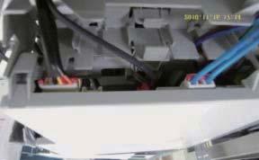
![New Function [ Indoor Terminal Block Safety Device ].](/docs-images/73/68357065/images/95-0.jpg "Thermal Fuse is installed in Terminal Block as below.")


 - In the above case, the change of all-in-one")
95 New Function [ Indoor Terminal Block Safety Device ]. Thermal Fuse is installed in Terminal Block as below. (Thermal Fuse is used to prevent PL caused by a defective connection of indoor and outdoor units) Thermal Fuse Terminal Block Internals Connection of terminal block and Main PBA 2. Thermal Fuse is opened when internal temperature of Terminal Block goes to a certain point due to Tracking caused by a defective connection of indoor and outdoor units. - When Thermal Fuse is opened, Main PBA (DC2V) is turned off and the indoor unit does not operate. (There is no problem with Main PBA in this case) - In the above case, the change of all-in-one Terminal Block will make Main PBA operate again. Circuit Block 3. Measurement method of fair/defective thermal fuse Fail Defective 0-38 Samsung Electronics
96 . Block Diagram - Indoor unit CONTROLLER HEAT EXCHANGER SENSOR ROOM TEMPERATURE SENSOR HUMIDITY SENSOR INFRARED SIGNAL IC-MCU H/V BLADE CONTROL INDOOR FAN MOTOR CONTROL OUTDOOR COMMUNICATION TEMPERATURE CONTROL HUMIDITY CONTROL TIMER BUZZER CONTROL WIFI MODEM COMMUNICATION DISPLAY CONTROL SPI DISPLAY PART DISPLAY - TIMER - GOODSLEEP - COMFORT CARE - 88 SEGMENT SPI REMOTE CONTROL POWER ON/OFF OSCILLATION CIRCUIT ZERO VOLTAGE DETECT MODE (AUTO,COOL,DRY,FAN, HEAT) PWM CONTROL SIGNAL SPI SELECT SMART SAVER SELECT TURBO OPERATION QUIET OPERATION STEPPING MOTOR CONTROL SIGNAL SPI CONTROL SIGNAL BUZZZER CONTROL SIGNAL PHOTO COUPLER OVER VOLTAGE PROTECTION INDOOR FAN MOTOR TEMPERATURE SELECT(UP/DOWN) WI-FI MODEM FAN SPEED SELECT (H/M/L/AUTO) BLADE-H/V MOVING SELECT COMMUNICATION SIGNAL OUTDOOR UNIT d'light COOL SELECT AUTO CLEAN SELECT BUZZER GOOD SLEEP SELECT ON,OFF TIMER SELECT(UP/DOWN) STEPPING MOTOR DRIVE SPI DRIVE BUZZER DRIVE SPI STEPPING MOTOR - BLDAE CONTROL(H/V) TEMP/HUMI SELECT BEEP ON/OFF SELECT DC5V DC2V DISPLAY ON/OFF SELECT WPS MODE SELECT AP MODE SELECT SMPS POWER BLOCK AC INPUT DC5V DC2V DC5V AC230V Samsung Electronics -
97 -2 Outdoor unit -2 Samsung Electronics
98 -2- Pre-inspection Notices. Check if you pulled out the AC power plug when you eliminate the PCB or front panel 2. Don't hold the PCB side not impose excessive force on it to eliminate the PCB 3. Don t pull the lead wire but hold the whole housing to connect or disconnect a connector to the PCB 4. In case of outdoor PCB disassembly, check first the complete discharge of condenser after minute power off -2-2 Inspection procedure. Check connector connection and peeling of PCB or bronze coating pattern when you think the PCB is broken 2. The PCB is composed of 3 parts Indoor Main part : MICOM and surrounding circuit, relay, fan motor sensing and driving circuit, temperature sensing circuit power circuit of SMPS, buzzer circuit. Communication circuit Display part : LED lamp, Switch, Remote-control module Outdoor Main part : MICOM and surround circuit, fan motor sensing and driving circuit, compressor driving circuit power circuit of SMPS, PFC control circuit, 4way circuit, communication circuit, OPTION (EEV control circuit, temperature sensing circuit) -2-3 Indoor detailed inspection procedure No Procedure Inspection Method Cause 2 Plug out and pull the PCB out of the control box Check the PCB fuse Supply power If the operating lamp twinkles at this time, the above )~3) have no relation ) Is st fuse disconnected? 2) Is 2nd fuse disconnected? Check the power voltage ) Is the BD7 input voltage 200Vac~240Vac? 2) Is the voltage between both terminal of IC02 pin #-#2 2Vdc?. Over current. Indoor Fan motor short. AC part and pattern short of Indoor PBA. Power cord is fault, Fuse open, Wrong Power cable Wiring, AC part is faulty. Switching Trans of Power circuit is faulty 3) Is the voltage between both terminal of IC02 pin #2-#3 5Vdc?. Power circuit is faulty, Load short ) Is the voltage over AC 80V being imposed on terminal #3-#5 of fan motor connector (CN72)?. Fan motor of the indoor is faulty 3 Press the ON/OFF button. Fan speed(high) 2. Continuous Operation 2) The fan motor of the indoor unit doesn't run. Fan motor connector(cn72) is faulty 3) The power voltage between terminal #3-#5 of the connector(cn72) is 0V. PBA is faulty Samsung Electronics -3
99 -2-4 Outdoor detailed inspection procedure No procedure Inspection Method Cause Plug out and pull the PCB out of the control box Check the PCB fuse (Wait 3 minutes after power off) 2 Check the Wiring 3 Supply power and operate the set (Use Remote-control, button in indoor set) 4 Check the LED lamp display ) Is st fuse disconnected? 2) Is indoor PBA faulty? ) Is the Compressor wire connected clockwise? 2) Is the Reactor wire connected normal? 3) Is the Fan wire connected normal? 4) Is the 4way wire connected normal? 5) Is the sensor wire connected Check the power voltage ) Is the voltage between Terminal block N()- 200Vac~240Vac?. Over current. AC part and pattern short of Indoor PBA. AC part and pattern short of Outdoor PBA. Wrong assembly. Installation(service) condition is bad. Power cord is faulty, Indoor PBA fault, Wrong Power cable Wiring. L,N,E wire wrong wiring (Terminal Block-PBA) 2) Is the PFC050(#26-#27) input. Fuse open voltage 200Vac~240Vac?. PTC020 open. RY02, RY022 is faulty. Outdoor Micom(IC5) error. Power circuit is faulty 3) Is the CE5 voltage 280Vdc~320dc?. Load short. PFC050 is faulty 3) Is the CE0 voltage 280Vdc~320dc?. Reactor wire is wrong connection. Switching Trans of Power circuit is 4) Is the voltage CE57 voltage 5Vdc? faulty Load short. Switching Trans of Power circuit is 5) Is the voltage CE55 voltage 2Vdc? faulty Load short. Switching Trans of Power circuit is 6) Is the voltage CE53 voltage faulty 3.3Vdc?. Load short ) Normal : RED on, GRN blink, YEL off 2) Abnormal. L,N,C wire wrong wiring - All off : check no power. Outdoor PBA is faulty - abnormal display : check error mode -4 Samsung Electronics
100 2. Reference Sheet 2- Low Refrigerant Pressure Distribution Note : Please measure the refrigerant pressure after the air conditioner operates on testing cooling mode during more than 0 minutes. Indoor Temp. Variation : 20 C ~ 32 C Outdoor Temp. Variation : -5 C ~ 45 C 2-2 Pressure & Capacity mark Power/Heat W cal/s kcal/h Btu/h HP kg.m/s Ib.m/s x , Samsung Electronics 2-
101 2-3 Q & A for Non-trouble Classification Class Description Q A The cooling is weak. When it is hot outside, its cooling capacity decreases due to the increase of the ambient temperature. When the dust filter gets blocked or warm outside air gets in, the cooling capacity will decrease. So, make sure to clean the dust filter frequently, prevent heat loss by closing the doors and insulate the cooling area by using curtains, blinds, shades or window tinting. Cooling Q The cooling is good generally. But, it gets weak when it is considerably hot. A It occurs when the outdoor unit is exposed to direct sun light and heat-up air is not ventilated well. So, set up a sunblind over the outdoor unit and keep stuff away from the unit to increase the ventilation. When the cooling capacity decreases during a heat wave, clean the heat exchanger of the outdoor unit or spray some cold water to the heat exchanger to increase the cooling capability. Q The cooling is weak. Does it need refrigerant charging? A It is not correct charging refrigerant regularly. Except that you have moved in several times or the connection pipes are broken, the refrigerant does not run low. So, when refrigerant is additionally charged, it could be costly and cause a product's failure. When the refrigerant leaks, all of it will escape in a short time resulting in cooling failure and no water coming out of the drain hose. So, if water comes out from the drain hose, it indicates the normal operation of the product and it does not need refrigerant charging. Leakage Q A Q A Q A Q A It fails to do cooling. When the air conditioner is set to ventilation or the desired temperature is set higher than the current temperature, it fails to do cooling. In this case, select cooling or set the desired temperature lower. It floods the floor. Place the drain hose properly. When it is not placed properly, the drain water would flow back flooding the floor. So, straighten out the drain hose for the water to be drained well. Water drips at the drain connection (service valve) of the outdoor unit. When a glass bottle is taken out of the refrigerator, moisture gets condensed on its surface due to the temperature differences. The same principle applies to the air conditioner. When cold refrigerant goes through the copper tube, moisture gets condensed on the surface of the tube and the connection areas. To prevent the water condensation, the pipes are insulated. But, the connection areas of the outdoor unit are not insulated for the purpose of maintenance or repair, and water gets condensed due to the temperature differences and drips down. Generally, it evaporates right away. But, when it drips much during muggy days, put a water pan on the floor. It leaks even though a drain pump is used. It occurs when the drain pump is plugged out or it is out of order. Check the power of the drain pump and the position of the drain hose, and when the pump is faulty, contact the drain pump manufacturer. Samsung Electronics do not manufacture drain pumps. So, we are not able to correct the drain pump problems. Q Whenever the air conditioner is turned on, it irritates my eyes and gives me a headache. Smells A There are no components in the air conditioner irritating the eyes and sending out chemical smells. But, when the air conditioner is turned on, other smell sources are sucked into the air conditioner and get out of it. So find and root out the smell sources. Generally, it occurs at a interior renovated place, a pharmacy, a gasoline handling place, a tire shop, a second-hand book shop or an electronic component handling place, when its chemical or musty smells are sucked in and sent out, it can be misled that the air conditioner generates them. 2-2 Samsung Electronics
102 Classification Class Description Q Whenever the air conditioner is turned on, it stinks. Smells Operation A Q A Q A Q A Q A Q A Q A Q A Q When are no components in the air conditioner sending out chemical smells. But, when the air conditioner is turned on, other smell sources are sucked into the air conditioner and get out of it. So, find and root out the smell sources. Generally, when the drain hose is taken out to the washing room or there are sources of smells such as a diaper bin, a shoe shelf or a socks bin, bad smells generate. Also, it occurs where glass cleaners or air fresheners are used; when they are sucked in interacting with dusts and moistures inside, bad smells generate. these kinds of organic materials noxious to human bodies. So, we recommend against the use of them. Whenever the air conditioner is turned on, it smells sour. When the room is papered recently, its paste smells would be sucked inside. Also, when the air conditioner is installed in the study room of young boys loving sweat-generating activities such as the basketball, excessive sweats evaporate and get sucked into the air conditioner resulting in bad smells. So, find and root out problem or refresh the room frequently. Whenever the air conditioner is turned on, it smells musty. It is due to the improper keeping of the product after its use. When keeping the product, dry up the inside with the operation of ventilation to prevent must. When the product is kept without drying up the inside with ventilation, mold would grow inside resulting in must. So, open the windows and switch on the ventilation function to get rid of the saturated smell inside. Whenever the air conditioner is turned on, it sends out bad smells such as stale smells. It occurs generally when there are pet animals in the house. Their smells stay at the same place. But, when the air conditioner is turned on, the air gets circulated resulting in the circulation of the smells. So, find and root out the problem or refresh the room frequently. It sends out bad smells. When the air filter is filthy, it could send out bad smells. So, clean the filter and ventilate the room with the windows open while operating the ventilation function. It won't start. There is a power failure or it is plugged out. Also, check if the power distribution panel is switched off. It goes off during operation. When the hot air does not escape properly, it goes off during operation. it occurs when it does not ventilate properly because the outdoor unit is covered, the back of the outdoor unit is blocked by a cardboard or a plywood panel, and the front of the outdoor unit is blocked by the closed window or other obstacles. Clear the above obstacles from the outdoor unit. It generally works properly. But, when it's considerably hot, it goes off during operation. It occurs when the outdoor unit is exposed to direct sunlight and the hot air does not escape properly. Set up a sun blind over the outdoor unit and clear the neighboring obstacles from the outdoor unit to provide good ventilation. When it goes off frequently during a heat wave, it would prevent the turnoff and increase the cooling capacity cleaning the outdoor unit or spraying some water to the heat exchanger. The remote controller won't operate. A When the batteries run out or the transmitter or receiver of the remote controller is blocked by obstacles, change the batteries or keep the obstacles away from the controlling area. Also, the remote controller may mot work under intensive light from a 3-wave length lamp or a neon sign due to the EMI. In this case, take the remote controller closer to the receiver. Samsung Electronics 2-3
103 Classification Class Description Installation Q A Q A Q A Q A Who installs the air conditioner? (Relocation/Re-installation) When relocating or re-installing the air conditioner, make sure to contact Samsung Electronics Service Center or Authorized Service Agent and have them to do the job. (If not, it could cause personal injury or product damage.) The cost for the relocation/re-installation of the air conditioner is subject to the customer's expense. There is a cost table. But, our service engineer needs to visit to total up the cost correctly. When you move in, make sure to contact Samsung Electronics Service Center or Authorized Service Agent in advance to streamline the process. Is it possible to install the outdoor unit outside? It is possible to install it at a designated place in the apartment or on the rooftop nearby. But, it's illegal hanging an angle iron case with the outdoor unit in it outside the apartment. Also, it is illegal obstructing passers-by with the outdoor unit installed outside. What can be done to install the outdoor unit facing the road because it is a commercial building? The following is an excerpt from building code going into effect from JUNE st "The exhaust pipe of a cooling or ventilation facility installed in a building adjacent to the streets of commercial or residential areas shall bel installed higher than 2 m to prevent the exhaust air from blowing directly to passersby and the current facilities shall be corrected by MAY 3 st 2005." So, please install it higher than 2 m or not to blow the hot exhausting air directly to passers-by. What about installing a windscreen during installation not to blow hot air directly to passers-by? When the hot air from the front of the outdoor unit is blocked, the product's performance will be affected and it will fail to operate properly. So, keep it at least 300mm away from its surrounding walls and give it good ventilation. 2-4 Samsung Electronics

104 2-4 Cleaning /Filter Change 2-4- Cleaning your Air Conditioner To get the best possible use out of your air conditioner, you must clean it regularly to remove the dust that accumulates on the air filter. Removing the Air filter There is a hole on the bottom right side of the filter. Put your finger in that hole to get a grip on the filter and slightly push it up to release the hooks from the bottom side. Then, pull it down to remove the filter from the main body. Air filter Cleaning the air filter Washable foam based air filter captures large particles from the air. The filter is cleaned with a vacuum or by hand washing. Remove the air filter from the main body. Clean the Air filter with a vacuum cleaner or soft brush. If dust is too heavy, rinse it with running water. Insert the air filter back in its original position. Dry the Air filter in a ventilated area. it once a week. Samsung Electronics 2-5
Basic model: AR12HSSDBWKNEU AR12HSSDBWKXEU
 Basic model: AR12HSSDBWKNEU AR12HSSDBWKXEU Model: AR09HSSFAWK AR12HSSFAWK AR09HSSFBWK AR12HSSFBWK AR12HSSFMWK AR09HSSFAWKNEU AR12HSSFAWKNEU AR09HSSFBWKNEU AR12HSSFBWKNEU AR12HSSFMWKNAX AR09HSSFAWK AR12HSSFAWK
SERVICE Manual FREE JOINT MULTI AIR CONDITIONER
 FREE JOINT MULTI AIR CONDITIONER INDOOR UNIT MH020FPEA MH023FPEA MH026FPEA MH035FPEA MH052FPEA MH8VP2-09 MH9VP2-07 MH9VP2-2 MH026FKEA MH035FKEA MH052FDEA OUTDOOR UNIT MH8VP2X MH9VP2X MH052FXEA2 MH068FXEA4
SPLIT-TYPE AIR CONDITIONER
 SPLIT-TYPE AIR CONDITIONER MODEL CODE INDOOR UNIT AR09MSWXCWKNCV AR12MSWXCWKNCV OUTDOOR UNIT AR09MSWXCWKXCV AR12MSWXCWKXCV AIR CONDITIONER CONTENTS 1. Precautions 2. Pr cations 3. Alignment and Adjustments
SERVICE Manual SYSTEM AIR CONDITIONER INDOOR UNIT GH052EAM GH070EAM OUTDOOR UNIT UH052EAMT UH070EAMT. 1. Product Specifications
 SYSTEM AIR CONDITIONER INDOOR UNIT GH052EAM GH070EAM OUTDOOR UNIT UH052EAMT UH070EAMT SERVICE Manual SYSTEM AIR CONDITIONER CONTENTS 1. Product Specifications 2. Disassembly and Reassembly 3. Set Up the
USER S MANUAL AQV09J Series AQV12J Series AQV18J Series AQV24J Series
 USER S MANUAL AQV09J Series AQV12J Series AQV18J Series AQV24J Series FRANÇAIS ENGLISH ESPAÑOL Split-type Air Conditioner (Cooling and Heating) E S F DB98-27555A(1) Safety Precautions Register your product
AIR CONDITIONER. Model : 1. Precautions. 2. Product Specifications. 3. Disassembly and Reassembly. 4. Troubleshooting. 5.
 SYSTEM AIR CONDITIONER Model : INDOOR UNIT AC012MNADCH/AA AC018MNADCH/AA AC024MNADCH/AA AC030MNTDCH/AA AC036MNTDCH/AA OUTDOOR UNIT AC012KXADCH/AA AC018JXADCH/AA AC024JXADCH/AA AC030JXADCH/AA AC036JXADCH/AA
USER S MANUAL AQV09V A Series AQV12V A Series AQV18V A Series AQV24V A Series
 USER S MANUAL AQV09V A Series AQV12V A Series AQV18V A Series AQV24V A Series ENGLISH FRANÇAIS ESPAÑOL Split - type Air Conditioner (Cooling and Heating) E S F DB98-27559A(1) Contents PREPARATION Safety
SPLIT TYPE ROOM AIR CONDITIONER CEILING TYPE (60Hz)
") SPLIT TYPE ROOM AIR CONDITIONER CEILING TYPE (60Hz) Indoor unit MS6YF Outdoor unit MR6YF CONTENTS SPECIFICATIONS... OUTLINE AND DIMENSIONS... REFRIGERANT SYSTEM DIAGRAM.... CIRCUIT DIAGRAM... INDOOR PCB
SPLIT TYPE ROOM AIR CONDITIONER CEILING TYPE (60Hz) Indoor unit MS6YF Outdoor unit MR6YF CONTENTS SPECIFICATIONS... OUTLINE AND DIMENSIONS... REFRIGERANT SYSTEM DIAGRAM.... CIRCUIT DIAGRAM... INDOOR PCB
SPLIT-TYPE AIR CONDITIONER
 SPLIT-TYPE AIR CONDITIONER INDOOR UNIT OUTDOOR UNIT Model Code : AR09HSFSJWKNCV AR09HSFSJWKXCV AR12HSFSJWKNCV AR12HSFSJWKXCV AR18HSFSJWKNCV AR18HSFSJWKXCV AR24HSFSJWKNCV AR24HSFSJWKXCV Basic Code : AR09HSFSHWKNCV
CEILING type (60Hz) SPLIT TYPE ROOM AIR CONDITIONER CONTENTS. Models
 SPLIT TYPE ROOM AIR CONDITIONER CONTENTS. Models") SPLIT TYPE ROOM AIR CONDITIONER CEILING type (60Hz) Models Indoor unit ABU6RSLX Outdoor unit AOU6RLX CONTENTS SPECIFICATIONS....................... OUTLINE AND DIMENSIONS............. REFRIGERANT SYSTEM
SPLIT TYPE ROOM AIR CONDITIONER CEILING type (60Hz) Models Indoor unit ABU6RSLX Outdoor unit AOU6RLX CONTENTS SPECIFICATIONS....................... OUTLINE AND DIMENSIONS............. REFRIGERANT SYSTEM
SPLIT-TYPE AIR CONDITIONER
 SPLIT-TYPE AIR CONDITIONER INDOOR UNIT Basic : AQB09JJWC AQB12JJWC Model : AQV09JA AQV12JA Model Code : AQV09JA AQV12JA OUTDOOR UNIT AQV09JAX AQV12JAX AIR CONDITIONER THE FEATURE OF PRODUCT High Energy
RC-54CA RO-50CA RC-54HA RO-50HA. SPLIT TYPE AIR CONDITIONER CASSETTE TYPE (50Hz) Indoor unit Outdoor unit
 Indoor unit Outdoor unit") SPLIT TYPE AIR CONDITIONER CASSETTE TYPE (50Hz) Indoor unit Outdoor unit RCW-54CB RO-50CA RC-54CA RO-50CA RC-54HA RO-50HA CONTENTS SPECIFICATIONS OUTLINE AND DIMENTIONS CIRCUIT DIAGRAM REFRIGERANT SYSTEM
SPLIT TYPE AIR CONDITIONER CASSETTE TYPE (50Hz) Indoor unit Outdoor unit RCW-54CB RO-50CA RC-54CA RO-50CA RC-54HA RO-50HA CONTENTS SPECIFICATIONS OUTLINE AND DIMENTIONS CIRCUIT DIAGRAM REFRIGERANT SYSTEM
WALL MOUNTED type SPLIT TYPE ROOM AIR CONDITIONER CONTENTS. Models
 SPLIT TYPE ROOM AIR CONDITIONER WALL MOUNTED type Models Indoor unit ASY9USCCW ASY9USCCW ASY12USCCW Outdoor unit AOY9USCC AOY9UFCC AOY12USCC CONTENTS SPECIFICATIONS................................... 1
SERVICE Manual CASSETTE TYPE AIR CONDITIONER INDOOR UNIT KH026EAM KH035EAM OUTDOOR UNIT UH026EAM UH035EAM. 1. Product Specifications
 CASSETTE TYPE AIR CONDITIONER INDOOR UNIT KH026EAM KH035EAM OUTDOOR UNIT UH026EAM UH035EAM SERVICE Manual AIR CONDITIONER CONTENTS 1. Product Specifications 2. Disassembly and Reassembly 3. Block Diagrams
SPLIT TYPE ROOM AIR CONDITIONER FLOOR CONSOLE / UNDER CEILING DUAL TYPE
 SPLIT TYPE ROOM AIR CONDITIONER FLOOR CONSOLE / UNDER CEILING DUAL TYPE Indoor unit ABYF8LAT ABYF8LAT ABYF8LAT ABYF8LAT ABYF8LBT ABYF8LBT ABYFLAT ABYFLAT ABYFLAT ABYFLAT ABYFLBT ABYFLBT Outdoor unit AOYA8LACL
Ductless Split Air Conditioner
 Ductless Split Air Conditioner Service Manual Indoor AW09ESVHA AWESVHA AW8ESVHA AWESVHA Outdoor U09ESVHA UESVHA U8ESVHA UESVHA Design may vary by model number. Please read this manual before using the
SERVICE MANUAL 42QHF009DS* 42QHF012DS* 42QHF018DS* 42QHF022DS* 38QUS009DS* 38QUS012DS* 38QUS018DS* 38QUS022DS* Indoor unit.
 SERVICE MANUAL Indoor unit Outdoor unit 42QHF009DS* 42QHF012DS* 42QHF018DS* 42QHF022DS* 38QUS009DS* 38QUS012DS* 38QUS018DS* 38QUS022DS* INDEX PART1 GENERAL INFORMATION PART2 ELECTRICAL DIAGRAM PART3 TROUBLE
CASSETTE type INVERTER MULTI AIR CONDITIONER. Models AUY12LBAB AUY14LBAB AOY18LMAK2
 INVERTER MULTI AIR CONDITIONER CASSETTE type Models Indoor unit AUY12LBAB AUY14LBAB Outdoor unit AOY18LMAK2 CONTENTS SPECIFICATIONS..................... 1 OUTLINE AND DIMENSIONS........... 2 REFRIGERANT
AIR CONDITIONER 4 WAY CASSETTE SERIES. 1. Precautions. 2. Product Specifications. 3. Disassembly and Reassembly. 4. Troubleshooting. 5.
 SYSTEM AIR CONDITIONER 4 WAY CASSETTE SERIES Model : INDOOR UNIT AC018JN4DCH/AA AC024JN4DCH/AA AC030JN4DCH/AA AC036JN4DCH/AA AC042JN4DCH/AA AC048JN4DCH/AA OUTDOOR UNIT AC018JXADCH/AA AC024JXADCH/AA AC030JXADCH/AA
AIR CONDITIONER OUTDOOR UNIT INDOOR UNIT. 1. Precautions
 MULTI AIR CONDITIONER INDOOR UNIT AJ007/009/012/018/024JNADCH AJ009/012/018JNNDCH AJ009/012/018JNLDCH OUTDOOR UNIT AJ020MCS3CH AJ024MCS4CH AJ030MCS4CH AIR CONDITIONER CONTENTS 1. Precautions 3. Disassembly
SYSTEM AIR CONDITIONER
 SYSTEM AIR CONDITIONER AHU SERIES Model : INDOOR UNIT AC018KNZDCH/AA AC024KNZDCH/AA AC030KNZDCH/AA AC036KNZDCH/AA AC042KNZDCH/AA AC048KNZDCH/AA AC054KNZDCH/AA OUTDOOR UNIT AC018JXADCH/AA AC024JXADCH/AA
Model name: AJ009JNNDCH AJ012JNNDCH AJ018JNNDCH AJ007JNADCH AJ009JNADCH AJ012JNADCH
 Model name: AJ009JNNDCH AJ012JNNDCH AJ018JNNDCH AJ007JNADCH AJ009JNADCH AJ012JNADCH MULTI AIR CONDITIONER INDOOR UNIT AJ018JNADCH AJ024JNADCH AJ009JNLDCH AJ012JNLDCH AJ018JNLDCH OUTDOOR UNIT AJ020JCJ2CH
SERVICE MANUAL K LIGHT COMMERCIAL
 SERVICE MANUAL 36 48 60K LIGHT COMMERCIAL Cassette indoor unit Under-ceiling indoor unit Ducted indoor unit 42QTD036DS* 42QTD048DS* 42QTD060DS* 42QZL036DS* 42QZL048DS* 42QZL060DS* 42QSM036DS* 42QSM048DS*
WALL MOUNTED type SPLIT TYPE ROOM AIR CONDITIONER CONTENTS. Models
 SPLIT TYPE ROOM AIR CONDITIONER WALL MOUNTED type Models Indoor unit ASY9USCCW ASY9USCCW ASY12USCCW Outdoor unit AOY9USCC AOY9UFCC AOY12USCC CONTENTS SPECIFICATIONS.................. 1 OUTLINE AND DIMENSIONS.........
YC ON-OFF SERIES. Service Manual
 YC ON-OFF SERIES Service Manual CONTENTS 1. Precaution... 3 1.1 Safety Precaution... 3 1.2 Warning... 3 2. Model Lists... 6 3. Dimension... 7 3.1 Indoor Unit... 7 3.2 Outdoor Unit... 11 4. Refrigerant
WALL MOUNTED type SPLIT TYPE ROOM AIR CONDITIONER. Models CONTENTS
 SPLIT TYPE ROOM AIR CONDITIONER WALL MOUNTED type Models Indoor unit ASY9USCCW ASY9USCCW ASY12USCCW Outdoor unit AOY9USCC AOY9UFCC AOY12USCC CONTENTS SPECIFICATIONS.................. 1 OUTLINE AND DIMENSIONS.........
DESIGN & TECHNICAL MANUAL
 AIR CONDITIONER Wall mounted type DESIGN & TECHNICAL MANUAL For Extra Cold Climate Area INDOOR ASU18RLF ASU24RLF OUTDOOR AOU18RLXFWH AOU24RLXFWH DR_AS014EF_04 2017.03.10 Notices: Product specifications
ASU18RLF ASU24RLF AOU18RLXFWH AOU24RLXFWH CONTENTS WALL MOUNTED TYPE ROOM AIR CONDITIONER FOR EXTRA LOW TEMP. DISTRICT
 WALL MOUNTED TYPE ROOM AIR CONDITIONER FOR EXTRA LOW TEMP. DISTRICT Indoor unit ASU8RLF ASURLF Outdoor unit AOU8RLXFWH AOURLXFWH CONTENTS SPECIFICATIONS.................... DIMENSIONS........................
TROUBLESHOOTING TROUBLESHOOTING. Indoor unit EEPROM parameter error. Indoor / outdoor units communication error. Zero-crossing signal detection error
 www.olmo-comfort.com TROUBLESHOOTING When below list for identification of error code occurs, please turn off air conditioner and disconnect power, and then contact the qualified professionals for service.
CASSETTE type INVERTER MULTI AIR CONDITIONER
 INVERTER MULTI AIR CONDITIONER CASSETTE type Models Indoor unit AUY12LBAB AUY14LBAB Outdoor unit AOY18LMAK2 CONTENTS SPECIFICATIONS..................... 1 OUTLINE AND DIMENSIONS........... 2 REFRIGERANT
Ductless Split Air Conditioner
 Ductless Split Air Conditioner Service Manual Indoor HSU09VHG(DB)-W HSUVHG(DB)-W HSU8VHH(DB)-W HSUVHG(DB)-W Outdoor HSU09VHG(DB)-G HSUVHG(DB)-G HSU8VHH(DB)-G HSUVHG(DB)-G Design may vary by model number.
CASSETTE type SPLIT TYPE AIR CONDITIONER. (60Hz) AUU18RCLX AUU24RCLX AUU36RCLX AUU42RCLX AOU18RLX AOU24RLX AOU36RLX AOU42RLX CONTENTS.
 AUU18RCLX AUU24RCLX AUU36RCLX AUU42RCLX AOU18RLX AOU24RLX AOU36RLX AOU42RLX CONTENTS.") SPLIT TYPE AIR CONDITIONER CASSETTE type (60Hz) Models Indoor unit AUU8RCLX AUURCLX AUU6RCLX AUURCLX Outdoor unit AOU8RLX AOURLX AOU6RLX AOURLX CONTENTS SPECIFICATIONS... DIMENSIONS... REFRIGERANT SYSTEM
SPLIT TYPE AIR CONDITIONER CASSETTE type (60Hz) Models Indoor unit AUU8RCLX AUURCLX AUU6RCLX AUURCLX Outdoor unit AOU8RLX AOURLX AOU6RLX AOURLX CONTENTS SPECIFICATIONS... DIMENSIONS... REFRIGERANT SYSTEM
SERVICE INSTRUCTION R410A. WALL MOUNTEDtype SPLIT TYPE ROOM AIR CONDITIONER INVERTER. Models Indoor unit Outdoor unit AO* R09LECN AO* R12LECN
 SERVICE INSTRUCTION SPLIT TYPE ROOM AIR CONDITIONER WALL MOUNTEDtype INVERTER Models Indoor unit Outdoor unit AS* A09LEC AS* A12LEC AO* R09LECN AO* R12LECN R410A CONTENTS 1. DESCRIPTION OF EACH CONTROL
KSIM20912-H216 KSIM30912-H216 KSIM40912-H216
 SERVICE MANUAL KLIMAIRE AIRCONDITIONER KSIM DC INVERTER MULTI TYPE KSIM20912-H216 KSIM30912-H216 KSIM40912-H216 DC MULTI OUTDOOR UNITS CONTENTS 1. General information of Outdoor Units...3 2 Features...4
FLOOR CONSOLE / UNDER CEILING DUAL type (60Hz)
") SPLIT TYPE ROOM AIR CONDITIONER FLOOR CONSOLE / UNDER CEILING DUAL type (60Hz) Models Indoor unit MSYF Outdoor unit MRUYF CONTENTS SPECIFICATIONS... OUTLINE AND DIMENSIONS... REFRIGERANT SYSTEM DIAGRAM...
SPLIT TYPE ROOM AIR CONDITIONER FLOOR CONSOLE / UNDER CEILING DUAL type (60Hz) Models Indoor unit MSYF Outdoor unit MRUYF CONTENTS SPECIFICATIONS... OUTLINE AND DIMENSIONS... REFRIGERANT SYSTEM DIAGRAM...
Service Manual & Installation Manual
 GE Consumer & Industrial Appliances Service Manual & Installation Manual Split System Air Conditioner Model numbers: GE AIR F24 GE AIR F34 GE AIR F41 1 2 3 Introduction and Features Model Remarks GE AIR
REFRIGERATOR SIDE BY SIDE TYPE CONTENTS REFRIGERATOR MODEL NAME : RH22H9010SR RH29H9000SR MODEL CODE : RH22H9010SR/AA RH29H9000SR/AA
 REFRIGERATOR SIDE BY SIDE TYPE MODEL NAME : RH22H9010SR RH29H9000SR MODEL CODE : RH22H9010SR/AA RH29H9000SR/AA REFRIGERATOR CONTENTS 1. PRECAUTIONS(SAFETY WARNINGS) 5 2. PRODUCT SPECIFICATIONS 8 3. DISASSEMBLY
ASU18RLF ASU24RLF AOU18RLXFW1 AOU24RLXFW1 SPLIT TYPE ROOM AIR CONDITIONER WALL MOUNTED TYPE CONTENTS
 SPLIT TYPE ROOM AIR CONDITIONER WALL MOUNTED TYPE Indoor unit ASU8RLF ASURLF Outdoor unit AOU8RLXFW AOURLXFW CONTENTS SPECIFICATIONS.................... DIMENSIONS........................ REFRIGERANT SYSTEM
FLOOR CONSOLE / UNDER CEILING DUAL type
 SPLIT TYPE ROOM AIR CONDITIONER FLOOR CONSOLE / UNDER CEILING DUAL type Models Indoor unit ABU8RULX ABURULX Outdoor unit AOU8RLX AOURLX CONTENTS SPECIFICATIONS... OUTLINE AND DIMENSIONS... REFRIGERANT
Part 3 Troubleshooting
 Part Troubleshooting What is in this part? This part contains the following chapters: Chapter See page Troubleshooting 2 Error Codes: Hydro-box 7 Error Codes: Outdoor Units Error Codes: System Malfunctions
DC INVERTER MULTI-SYSTEM AIR CONDITIONER
 TECHNICAL & SERVICE MANUAL OUTDOOR UNIT : CU-3KE19NBU CU-4KE24NBU CU-4KE31NBU DC INVERTER MULTI-SYSTEM AIR CONDITIONER Capacity at 0V 19,100 BTU/h,200 BTU/h 30,600 BTU/h Outdoor Model No. CU-3KE19NBU CU-4KE24NBU
Part 5. Troubleshooting. 1. Normal Air Conditioner Phenomenon Air Conditioner Protection in Common
 Part 5 1. Normal Air Conditioner Phenomenon... 1611 2. Air Conditioner Protection in Common... 1611 3. Malfunction Code and... 162 160 1. Normal Air Conditioner Phenomenon 1.1 When outdoor unit appears
4. Disassembly and Reassembly
 4. Disassembly and Reassembly Stop operation of the air conditioner and remove the power cord before repairing the unit. 4-1 Indoor Unit 4-1-1 MH FPEA /MH VP2-1 Front Panel 1) Stop the air conditioner
DESIGN & TECHNICAL MANUAL
 AIR CONDITIONER Wall mounted type DESIGN & TECHNICAL MANUAL INDOOR ASYG07KGTA ASYG09KGTA ASYG12KGTA ASYG14KGTA OUTDOOR AOYG07KGCA AOYG09KGCA AOYG12KGCA AOYG14KGCA DR_AS049EF_02 2017.10.11 Notices: Product
INSTALLATION MANUAL. Split-type Air Conditioner (Cooling and Heating) Outdoor Unit UQB09JJWC UQB12JJWC. Indoor Unit AQB09JJWC AQB12JJWC
 Outdoor Unit UQB09JJWC UQB12JJWC. Indoor Unit AQB09JJWC AQB12JJWC") AQB09JJ6WC_IM_E_2585 2006.4.17 4:26 PM Page 17 INSTALLATION MANUAL Indoor Unit AQB09JJWC AQB12JJWC Outdoor Unit UQB09JJWC UQB12JJWC ENGLISH FRANÇAIS ESPAÑOL Split-type Air Conditioner (Cooling and Heating)
AQB09JJ6WC_IM_E_2585 2006.4.17 4:26 PM Page 17 INSTALLATION MANUAL Indoor Unit AQB09JJWC AQB12JJWC Outdoor Unit UQB09JJWC UQB12JJWC ENGLISH FRANÇAIS ESPAÑOL Split-type Air Conditioner (Cooling and Heating)
R410A. WALL MOUNTEDtype INVERTER SPLIT TYPE ROOM AIR CONDITIONER. Models Indoor unit Outdoor unit AO*G09LTCN AO*G12LTCN AO*G14LTCN
 SERVICE INSTRUCTION SPLIT TYPE ROOM AIR CONDITIONER WALL MOUNTEDtype INVERTER Models Indoor unit Outdoor unit AS*G09LTCB AS*GLTCB AS*G4LTCB AO*G09LTCN AO*GLTCN AO*G4LTCN R40A CONTENTS. DESCRIPTION OF EACH
INSTALLATION MANUAL. Split-type Air Conditioner (Cooling and Heating) Indoor Unit AQB18J6WC AQB24J2WC. Outdoor Unit UQB18J6WC UQB24J2WC
 Indoor Unit AQB18J6WC AQB24J2WC. Outdoor Unit UQB18J6WC UQB24J2WC") AQB8J6WC_IM_E_25864 2006.4.4 3:29 PM Page 7 INSTALLATION MANUAL Indoor Unit AQB8J6WC AQB24J2WC Outdoor Unit UQB8J6WC UQB24J2WC ENGLISH FRANÇAIS ESPAÑOL Split-type Air Conditioner (Cooling and Heating)
AQB8J6WC_IM_E_25864 2006.4.4 3:29 PM Page 7 INSTALLATION MANUAL Indoor Unit AQB8J6WC AQB24J2WC Outdoor Unit UQB8J6WC UQB24J2WC ENGLISH FRANÇAIS ESPAÑOL Split-type Air Conditioner (Cooling and Heating)
R410A. WALL MOUNTEDtype INVERTER SPLIT TYPE ROOM AIR CONDITIONER. Models Indoor unit Outdoor unit AOYG07LEC AOYG09LEC AOYG12LEC AOYG14LEC
 SERVICE INSTRUCTION SPLIT TYPE ROOM AIR CONDITIONER WALL MOUNTEDtype INVERTER Models Indoor unit Outdoor unit ASYG07LECA ASYG09LECA ASYG12LECA ASYG14LECA AOYG07LEC AOYG09LEC AOYG12LEC AOYG14LEC R410A CONTENTS
SERVICE MANUAL ROOM AIR CONDITIONER TAN/TAG-A28FWIS TAN/TAG-A32FWIS CONTENTS
 SERVICE MANUAL ROOM AIR CONDITIONER TAN/TAG-A28FWIS TAN/TAG-A32FWIS CONTENTS SPECIFICATION... 1 FUNCTIONS... 5 SERVICE FUNCTION EXPLANATION... 7 OPERATION DETAILS... 8 TROUBLESHOOTING GUIDE... 13 PERFORMANCE
THROUGH-WALL AIR-TO-AIR HEAT PUMP AND AIR CONDITIONER. Instruction Manual. Model AMB-12H
 THROUGH-WALL AIR-TO-AIR HEAT PUMP AND AIR CONDITIONER Instruction Manual Model AMB-12H PLEASE READ THIS INSTRUCTION MANUAL CAREFULLY BEFORE USING THIS UNIT. Table of Contents 1. SAFETY WARNINGS 2 2. CONSTRUCTION...
DESIGN & TECHNICAL MANUAL
 AIR CONDITIONER Wall mounted type DESIGN & TECHNICAL MANUAL INDOOR ASYG18KLCA ASYG24KLCA OUTDOOR AOYG18KLTA AOYG24KLTA DR_AS069EF_01 2018.03.16 Notices: Product specifications and design are subject to
Room Air Conditioner CP06 & CP08. Chill 115 Volts. Service & Parts Manual THE EXPERTS IN ROOM AIR CONDITIONING _02
 Room Air Conditioner Service & Parts Manual 2014-2015 CP06 & CP08 Chill 115 Volts THE EXPERTS IN ROOM AIR CONDITIONING 93011401_02 CONTENTS 1. PREFACE 1.1 SAFETY PRECAUTIONS...2 1.2 INSULATION RESISTANCE
DESIGN & TECHNICAL MANUAL
 AIR CONDITIONER Wall mounted type DESIGN & TECHNICAL MANUAL INDOOR ASYG07LMCE ASYG09LMCE ASYG12LMCE ASYG14LMCE OUTDOOR AOYG07LMCE AOYG09LMCE AOYG12LMCE AOYG14LMCE DR_AS037EF_01 2016.12.05 Notices: Product
SERVICE INSTRUCTION R410A. WALL MOUNTEDtype INVERTER SPLIT TYPE ROOM AIR CONDITIONER. Models Indoor unit Outdoor unit AOU9RLS2H AOU12RLS2H AOU15RLS2H
 SERVICE INSTRUCTION SPLIT TYPE ROOM AIR CONDITIONER WALL MOUNTEDtype INVERTER Models Indoor unit Outdoor unit ASU9RLS ASURLS ASU5RLS AOU9RLSH AOURLSH AOU5RLSH R40A CONTENTS. DESCRIPTION OF EACH CONTROL
SPLIT TYPE ROOM AIR CONDITIONER. WALL MOUNTEDtype INVERTER. Models Indoor unit Outdoor unit AOU 9RLFW1 AOU12RLFW1 ASU 9RLF1 ASU12RLF1 R410A
 SERVICE INSTRUCTION SPLIT TYPE ROOM AIR CONDITIONER WALL MOUNTEDtype INVERTER Models Indoor unit Outdoor unit ASU 9RLF ASURLF AOU 9RLFW AOURLFW R40A CONTENTS. DESCRIPTION OF EACH CONTROL OPERATION. COOLING
OWNER S INSTRUCTIONS MANUAL DE INSTRUCCIONES MANUEL D UTILISATION ISTRUZIONI PER L USO MANUAL DE INSTRUÇÕES GEBRAUCHSANWEISUNG π Ã
 OWNER S INSTRUCTIONS MANUAL DE INSTRUCCIONES MANUEL D UTILISATION ISTRUZIONI PER L USO MANUAL DE INSTRUÇÕES GEBRAUCHSANWEISUNG π Ã Indoor unit SH09BPD SH12BPD Outdoor unit SH09BPDX SH12BPDX Split-type
SERVICE Manual CEILING TYPE AIR CONDITIONER INDOOR UNIT FH052EZA FH070EZA OUTDOOR UNIT FH052EZX FH070EZX. 1. Product Specifications
 CEILING TYPE AIR CONDITIONER INDOOR UNIT FH052EZA FH070EZA OUTDOOR UNIT FH052EZX FH070EZX SERVICE Manual AIR CONDITIONER CONTENTS 1. Product Specifications 2. Trouble Shooting 3. Block Diagrams 4. Disassembly
SERVICE MANUAL MUZ-DM25VA - E1, ER1, ET1 MUZ-DM35VA - E1, ER1, ET1 OUTDOOR UNIT. No. OBH751. Models HFC R410A
 OUTDOOR UNIT SERVICE MANUAL HFC utilized R410A. Models MUZ-DM25VA - E1, ER1, ET1 MUZ-DM35VA - E1, ER1, ET1 Indoor unit service manual MSZ-DM VA Series (OBH750) CONTENTS 1. TECHNICAL CHANGES 2 2. PART NAMES
ROOM AIR CONDITIONER INDOOR UNIT OUTDOOR UNIT AQ09A5(6)MA UQ09A5(6)MA AQ12A5(6)MC UQ12A5(6)MC SERVICE
MA UQ09A5(6)MA AQ12A5(6)MC UQ12A5(6)MC SERVICE") ROOM AIR CONDITIONER INDOOR UNIT AQ09A5(6)MA AQ2A5(6)MC OUTDOOR UNIT UQ09A5(6)MA UQ2A5(6)MC SERVICE Manual AIR CONDITIONER CONTENTS. Installation 2. Disassembly and Reassembly. Troubleshooting 4. Exploded
ROOM AIR CONDITIONER INDOOR UNIT AQ09A5(6)MA AQ2A5(6)MC OUTDOOR UNIT UQ09A5(6)MA UQ2A5(6)MC SERVICE Manual AIR CONDITIONER CONTENTS. Installation 2. Disassembly and Reassembly. Troubleshooting 4. Exploded
Room Air Conditioner Service and Parts Manual
 Cool Dry Temp Mode Room Air Conditioner Service and Parts Manual F Fan Speed hr Timer 0n 0ff Money Saver Fan Only Auto Swing Power CP06 CP08 93011401_01 CONTENTS 1. PREFACE 1.1 SAFETY PRECAUTIONS...2 1.2
Owner s Manual Super-Slim Four-Way Cassette
 CASSETTE- TYPE AIR CONDITIONER Owner s Manual Super-Slim Four-Way Cassette IMPORTANT NOTE: Read this manual carefully before installing or operating your new air conditioning unit. Make sure to save this
Fast Track Troubleshooting
 Fast Track Troubleshooting Model: RH22** Bulletins: IMPORTANT SAFETY NOTICE For Technicians Only This service data sheet is intended for use by persons having electrical, electronic, and mechanical experience
Split-type Room Air Conditioner (Cool) Aire acondicionado doméstico sistema Split (Refrigeración) Climatiseur de type Séparé (Refroidissement)
 Aire acondicionado doméstico sistema Split (Refrigeración) Climatiseur de type Séparé (Refroidissement)") OWNER S INSTRUCTIONS MANUAL DE INSTRUCCIONES MANUEL D UTILISATION Indoor unit AS24A5(6)RCD AST24A5(6)RB(E)D SC24AC5(6) SC24TA5(6)(8)D AS18A9(0)RB(C)(D)(E)D SC18ZA9(0)D SC18AC9(0) AS12AA(B)MB(E) SC12ZAA(B)
OWNER S INSTRUCTIONS MANUAL DE INSTRUCCIONES MANUEL D UTILISATION Indoor unit AS24A5(6)RCD AST24A5(6)RB(E)D SC24AC5(6) SC24TA5(6)(8)D AS18A9(0)RB(C)(D)(E)D SC18ZA9(0)D SC18AC9(0) AS12AA(B)MB(E) SC12ZAA(B)
AIR CONDITIONER OUTDOOR UNIT INDOOR UNIT. 1. Precautions
 MULTI AIR CONDITIONER INDOOR UNIT AJ009JNNDCH/AA AJ012JNNDCH/AA AJ018JNNDCH/AA AJ007JNADCH/AA AJ009JNADCH/AA AJ012JNADCH/AA AJ018JNADCH/AA AJ024JNADCH/AA AJ009JNLDCH/AA AJ012JNLDCH/AA AJ018JNLDCH/AA AJ009NBNDCH/AA
SERVICE MANUAL MSZ-GL06NA - U1 MSZ-GL09NA - U1 MSZ-GL12NA - U1 MSZ-GL15NA - U1 MSZ-GL18NA - U1 MSZ-GL24NA - U1
 Revision B: 3. SPECIFICATION has been corrected. Please void OBH732 REVISED EDITION-A. INDOOR UNIT SERVICE MANUAL. OBH732 REVISED EDITION-B Models MSZ-GL06NA - U1 MSZ-GL09NA - U1 MSZ-GL12NA - U1 MSZ-GL15NA
SERVICE MANUAL MUZ-FH25VE MUZ-FH35VE MUZ-FH50VE OUTDOOR UNIT. No. OBH624. Models HFC. Revision A: MUZ-FH50VE- E1 has been added. Please void OBH624.
 SPLIT-TYPE AIR CONDITIONERS Revision A: MUZ-FH50VE- E1 has been added. Please void OBH624. OUTDOOR UNIT SERVICE MANUAL HFC utilized R410A. OBH624 REVISED EDITION-A Models MUZ-FH25VE MUZ-FH35VE MUZ-FH50VE
KTIR AIR CONDITIONER SERIES TROUBLESHOOTING
 TROUBLESHOOTING AIR CONDITIONER KTIR SERIES Thank you very much for purchasing our air conditioner, please read this owner's manual carefully before using your air conditioner TROUBLES AND CAUSES Before
CASSETTE type (50Hz) SPLIT TYPE AIR CONDITIONER. Models Indoor unit Outdoor unit
 SPLIT TYPE AIR CONDITIONER. Models Indoor unit Outdoor unit") SPLIT TYPE AIR CONDITIONER CASSETTE type (50Hz) Models Indoor unit Outdoor unit RCW-12HA RO-12HB C O N T E N T S SPECIFICATIONS........................................ 1 OUTLINE AND DIMENSIONS..............................
SPLIT TYPE AIR CONDITIONER CASSETTE type (50Hz) Models Indoor unit Outdoor unit RCW-12HA RO-12HB C O N T E N T S SPECIFICATIONS........................................ 1 OUTLINE AND DIMENSIONS..............................
TABLE OF CONTENTS REFRIGERATOR-FREEZER. Model No. NR-BN34FX1 Model No. NR-BN34FW1
 Order Number GORR1405001CE REFRIGERATOR-FREEZER Model No. NR-BN34FX1 Model No. NR-BN34FW1 Product-Color X:Stainless W:White Destination E(Europe Continental) B(U.K.) TABLE OF CONTENTS PAGE 1 Safety Precautions-----------------------------------------------
SERVICE MANUAL MSC-GE20VB - E1 MSC-GE25VB - E1 MSC-GE35VB - E1 MS-GE50VB - E1 MSH-GE50VB - E1 INDOOR UNIT. No. OBH529. Models
 SPLIT-TYPE AIR CONDITIONERS INDOOR UNIT SERVICE MANUAL. OBH529 Models MSC-GE20VB - E1 MSC-GE25VB - E1 MSC-GE35VB - E1 MS-GE50VB - E1 MSH-GE50VB - E1 service manual MU-GA VB Series (OB386) MUH-GA VB Series
DuctlessAire ES Series. Service Manual 2016 ABSSA-B4-1601
 DuctlessAire ES Series Service Manual 2016 ABSSA-B4-1601 CONTENTS 1. Precaution... 1 1.1 Safety Precaution... 1 1.2 Warning... 1 2. Model list... 4 3. Dimension... 5 3.1 Indoor Unit... 5 3.2 Outdoor Unit...
Window-Type Air Conditioner
 GE Appliances Window-Type Air Conditioner Owner's Manual ASM12ABS1 ASM14ABD1 ASM18DBS1 ASM24DBD1 E S DB68-02106A(1) E-19 Safety Precautions The following safety precautions must be taken when using your
Installation Instructions
 40MAQ High Wall Ductless Split System Sizes 09 to 36 Installation Instructions NOTE: Read the entire instruction manual before starting the installation TABLE OF CONTENTS PAGE SAFETY CONSIDERATIONS 2 PARTS
TECHNICAL DATA & SERVICE MANUAL MTF94C5TAA
 TECHNICAL DATA & SERVICE MANUAL MTF94C5TAA 0.8180.472.0 07/2005 Page 1. SPECIFICATIONS 3 1-1 Unit Specifications 3 1-2 Major Component Specifications 4 2. DIMENSIONAL DATA 6 2-1 Unit Dimensions 6 3. ELECTRICAL
Fast Track Troubleshooting
 Fast Track Troubleshooting Models Covered: RF266AD**/XAA French Door Refrigeration IMPORTANT SAFETY NOTICE For Technicians Only This service data sheet is intended for use by persons having electrical,
EVAPORATIVE AIR COOLER SERVICE MANUAL
 EVAPORATIVE AIR COOLER SERVICE MANUAL CAUTION: Before servicing the unit, read the Safety Precautions in this manual. Only for authorized service. MODEL NO.: CL30XC & CHL30XC (INDOOR USE ONLY) CONTENT
WINDOW TYPE ROOM AIR CONDITIONER OPERATION AND INSTALLATION MANUAL
 MODEL RA-0LDF RA-3LDF WINDOW TYPE ROOM AIR CONDITIONER OPERATION AND INSTALLATION MANUAL AIR DEFLECTORS VERTICAL DEFLECTORS Vertical de ectors at both sides of outlets can be set to either auto-swing or
3 In 1 AIR CONDITIONER with REMOTE CONTROL MODEL NO: CA9000 PART No: OPERATION & MAINTENANCE INSTRUCTIONS
 3 In 1 AIR CONDITIONER with REMOTE CONTROL MODEL NO: CA9000 PART No: 32305600 OPERATION & MAINTENANCE INSTRUCTIONS 0304 Parts List Item Part No Description Qty 1 FT900001 Top Cover 1 2 FT900002 Filter
Portable Air Conditioner Instruction Manual
 Portable Air Conditioner Instruction Manual WA-1240AE1: 12,000BTU (cooling only) WA-1240H1: 12,000BTU (cooling & heating) WA-1420E1: 14,000BTU (cooling only) WA-1420H1: 14,000BTU (cooling & heating) Thank
OWNER S MANUAL. R 410A Ductless Split System Air Conditioner and Heat Pump
 R 410A Ductless Split System Air Conditioner and Heat Pump Models DLC4(A/H) Outdoor Unit, DLF4(A/H) Indoor Unit Sizes 9K, 12K, 18K, 24K, 30K and 36K Please read the operating instructions and safety precautions
SERVICE INSTRUCTION R410A. WALL MOUNTEDtype INVERTER SPLIT TYPE ROOM AIR CONDITIONER. Models Indoor unit Outdoor unit AO*G24LFL AO*G24LFCC AO*G30LFT
 SERVICE INSTRUCTION SPLIT TYPE ROOM AIR CONDITIONER WALL MOUNTEDtype INVERTER Models Indoor unit Outdoor unit AS*G4LFCA AS*G4LFCC AS*G0LFCA AO*G4LFL AO*G4LFCC AO*G0LFT R40A CONTENTS. DESCRIPTION OF EACH
INSTALLATION MANUAL Duct Type Series MH FECA
 INSTALLATION MANUAL Duct Type Series MH FECA ENGLISH FRANÇAIS ESPAÑOL Free Joint Multi Air Conditioner (Cooling and Heating) E S F DB98-960A() Safety Precautions The following safety precautions must be
AIR CONDITIONER. Please read this owner, s manual carefully before using the air conditioner, and keep this manual for the future reference.
 Owner, s Manual AIR CONDITIONER Please read this owner, s manual carefully before using the air conditioner, and keep this manual for the future reference. CONTENTS 1. Safety Precaution-------------------------------------------------------------------------------1
AIR CONDITIONER OUTDOOR UNIT AM036NXMDCR AM048NXMDCR AM053NXMDCR AM060NXMDCR. Product Specifications. Disassembly and Reassembly
 SYSTM AIR CONDITIONR OUTDOOR UNIT AM036NXMDCR AM048NXMDCR AM053NXMDCR AM060NXMDCR AIR CONDITIONR CONTNTS Product Specifications Disassembly and Reassembly Refrigerant pipe installation Troubleshooting
PARTS & ACCESSORIES INSTALLATION AND SAFETY INSTRCUTIONS ITEM NO.:60006PC SAFETY PRECAUTION. Canopy. Downrod. Housing. Blade. Transmitter CR2032/3V
 L I G H T I N G INSTALLATION AND SAFETY INSTRCUTIONS ITEM NO.:000PC SAFETY PRECAUTION PARTS & ACCESSORIES Canopy Downrod Housing IMPORTANT : PLEASE READ BEFORE INSTALLATION.. Do not connect this remote
GMSG OWNER S MANUAL SPLIT-SYSTEM ROOM AIR CONDITIONER CONTENTS
 GMSG OWNER S MANUAL SPLIT-SYSTEM ROOM AIR CONDITIONER CONTENTS SAFETY PRECAUTIONS 3 PARTS NAMES 5 OPERATING TEMPERATURE 6 MANUAL OPERATION 7 ADJUSTING AIRFLOW DIRECTION 8 HOW THE AIR CONDITIONER WORKS
DC INVERTER MULTI-SYSTEM AIR CONDITIONER
 TECHNICAL & SERVICE MANUAL INDOOR UNIT : CS-MKE9NB4U & CZ-18BT1U CS-MKE12NB4U & CZ-18BT1U CS-KE18NB4UW & CZ-18BT1U DC INVERTER MULTI-SYSTEM AIR CONDITIONER Capacity 9,000BTU / h 11,900BTU / h 17,500BTU
Air Conditioner CONTENTS CS-E18EKU CU-E18EKU CS-E21EKU CU-E21EKU. Order No: MAC C1
 Order No: MAC0512115C1 CS-E18EKU CU-E18EKU CS-E21EKU CU-E21EKU Air Conditioner CONTENTS Page Page 1 Safety Precautions 3 2 Specification 5 2.1. CS-E18EKU CU-E18EKU 5 2.2. CS-E21EKU CU-E21EKU 7 3 Location
SERVICE MANUAL. Inverter Wall Mounted Single Split. MODELS Cooling Only. Heatpump SM-5WM-Y-NA-B1
 SERVICE MANUAL Inverter Wall Mounted Single Split MODELS Cooling Only FTKB09AXVJU FTKB12AXVJU FTKB18AXVJU FTKB24AXVJU FTKN09AXVJU FTKN12AXVJU FTKN18AXVJU FTKN24AXVJU Heatpump FTXB09AXVJU FTXB12AXVJU FTXB18AXVJU
Display Cases Deli Cases Service Manual
 Turbo Air Speed up the Pace of Innovation CAUTION! PLEASE KEEP POWER SWITCH ON BEFORE OPERATING THIS EQUIPMENT Display Cases Deli Cases Service Manual Please read this manual completely before attempting
Utopian Split A/C. Thank you for purchasing this quality Split A/C system!
 Utopian Split A/C Thank you for purchasing this quality Split A/C system! Please read through this manual completely, and keep it in case you need to reference the information in the future. Any operation
INVERTER ONE-TWO/ONE-THREE/ONE-FOUR/ONE-FIVE SPLIT-TYPE AIR CONDITIONER
 INVERTER ONE-TWO/ONE-THREE/ONE-FOUR/ONE-FIVE SPLIT-TYPE AIR CONDITIONER Owner s Manual Model: 3554190/3554191/3554192/3554193 3554194/3554195/3554196/3554197 IMPORTANT NOTE: Read this manual carefully
Operating Instructions Air Conditioner
 F56579 Operating Instructions Air Conditioner Indoor Unit Outdoor Unit CS-E18GKR CS-E1GKR CS-E4GKR CS-E8GKR CU-E18GKR CU-E1GKR CU-E4GKR CU-E8GKR Before operating the unit, read these operating instructions
Technical Manual of AUX Air Conditioner CONTENTS. Product Specification...1. Refrigeration Diagram...3. Introductions of Installation.
 CONTENTS Product Specification......1 Refrigeration Diagram....3 Introductions of Installation. 6 Remote Controller Introductions..13 Brief Introduction for Usage...21 Wiring Diagram....27 Troubleshooting
OWNER S INSTRUCTIONS MANUAL DE INSTRUCCIONES MANUEL D UTILISATION ISTRUZIONI PER L USO MANUAL DE INSTRUÇÕES GEBRAUCHSANWEISUNG
 OWNER S INSTRUCTIONS MANUAL DE INSTRUCCIONES MANUEL D UTILISATION ISTRUZIONI PER L USO MANUAL DE INSTRUÇÕES GEBRAUCHSANWEISUNG π Ã àçëíêìäñàü èéãúáéçäíöãü MH026FPEA MH035FPEA MH052FPEA ENGLISH ESPAÑOL
Fast Track Troubleshooting
 Fast Track Troubleshooting Models Covered: RS263BBBB/XAA RS263BBSH/XAA RS263BBWP/XAA RS265LBBP/XAA RS265LBWP/XAA SxS Refrigeration Notice: Bulletin on parts change Thermal Fuse to Bi-Metal Publication
DUCT type. SPLIT TYPE AIR CONDITIONER (50Hz)
") SPLIT TYPE AIR CONDITIONER (50Hz) DUCT type Models Indoor unit Outdoor unit ARY0ELA AOY0EPBL CONTENTS SPECIFICATIONS.............................. OUTLINE AND DIMENSIONS...................... CIRCUIT DIAGRAM............................
SPLIT TYPE AIR CONDITIONER (50Hz) DUCT type Models Indoor unit Outdoor unit ARY0ELA AOY0EPBL CONTENTS SPECIFICATIONS.............................. OUTLINE AND DIMENSIONS...................... CIRCUIT DIAGRAM............................
TECHNICAL & SERVICE MANUAL. Ceiling Concealed
 STAND BY DEFROST CHECK CLOCK ON OFF NOT AVAILABLE FILTER CHECK MODE TEST RUN FUNCTION SPLIT-TYPE, HEAT PUMP AIR CONDITIONERS TECHNICAL & SERVICE MANUAL Series SEZ Ceiling Concealed R40A.OC0 REVISED EDITION-A
KSD-35 DR11 KUE-35 DVN11
 FLOOR-STANDING TYPE AIR CONDITIONER Owner s Manual Floor-Standing Type KSD-35 DR11 KUE-35 DVN11 IMPORTANT NOTE: Read this manual carefully before installing or operating your new air conditioning unit.
DUCT type. Большая библиотека технической документации каталоги, инструкции, сервисные мануалы, схемы.
 SPLIT TYPE AIR CONDITIONER (50Hz) DUCT type Models Indoor unit Outdoor unit RD-25CA RD-25HA RD-30CA RD-30HA RO-25CA RO-25HA RO-30CA RO-30HA C O N T E N T S SPECIFICATIONS.............................................