VRF inverter multi-system Air-Conditioners. 50Hz 13KX02E EU/EEA
|
|
|
- Conrad McCarthy
- 6 years ago
- Views:
Transcription

1 2013 VRF inverter multi-system ir-conditioners 50Hz 13KX02E EU/EE

2 R4 History of Technologies more efficient, more sophisticated KX2 KX4 KX6 (8~12HP) 2
3 Line Up Contents Introduction 4~15 Outdoor units 16~47 s Control systems 48~83 84~93 High Head series 94~97 Refresh KX outdoor units Further information 0~3 3

4 R4 Product Line Up <Outdoor units> from 11.2 up to 136.0(24models) Single use (1 Outdoor unit) Capacity Model Code : BTU / h kcal / h 4HP ,200 9,630 5HP 14 47,800 12,040 6HP ,900 13,330 8HP ,400 19,260 HP 28 95,500 24,080 12HP ,300 28,8 14HP ,500 34,400 16HP ,600 38,700 18HP ,000 43,340 20HP ,0 48,160 22HP ,900 52,890 24HP ,000 58,480 Capacity Model Index : BTU / h kcal / h 26HP ,800 63,2 28HP ,000 68,800 30HP ,0 73,0 Combination use (2 Outdoor units) 32HP ,0 77,400 34HP ,600 82,560 36HP ,700 86,860 38HP ,400 91,590 40HP ,600 97,180 42HP ,700 1,480 44HP ,400 6,2 46HP , ,800 48HP ,0 116,960 4HP 5HP 6HP FDC112KXEN6 FDC140KXEN6 FDC112KXES6 FDC140KXES6 For EU/EE area, refer to the bottom part of page 17. FDC155KXEN6 FDC155KXES6 1-phase V 3-phase V 8HP HP 12HP FDC224KXE6 FDC280KXE6 FDC335KXE6 12HP 14HP 16HP 18HP FDC335KXE6-K FDC400KXE6 FDC450KXE6 FDC504KXE6 20HP 20HP 22HP 24HP FDC560KXE6 FDC560KXE6-K FDC615KXE6 FDC680KXE6 26HP 28HP 30HP 32HP 34HP 36HP FDC735KXE6 FDC800KXE6 FDC850KXE6 FDC900KXE6 FDC960KXE6 FDCKXE FDC335KXE6-K FDC400KXE6 FDC400KXE6 FDC400KXE6 FDC400KXE6 FDC450KXE6 FDC450KXE6 FDC450KXE6 FDC450KXE6 FDC504KXE6 FDC504KXE6 FDC504KXE6 38HP 40HP 42HP 44HP 46HP 48HP FDC65KXE6 FDC1130KXE6 FDC1180KXE6 FDC1235KXE6 FDC1300KXE6 FDC1360KXE FDC504KXE6 FDC560KXE6 FDC560KXE6 FDC560KXE6 FDC560KXE6-K FDC615KXE6 FDC615KXE6 FDC615KXE6 FDC335KXE6-K & FDC560KXE6-K are only used for combining with other models. FDC615KXE6 FDC680KXE6 FDC680KXE6 FDC680KXE6 4
5 <s> Wide variety of 17 types 92 models range of 17 types of exposed or concealed indoor units, in wide capacities, 92 indoor models. The best selection of indoor units for many kinds of rooms and preference can be available from our full lineup. s lineup Type Capacity Model Code : 0.5HP 0.8HP 1HP 1.25HP 1.6HP 2HP 2.5HP 3.2HP 4HP 5HP 6HP 8HP HP way FDT 4way Compact (600 x 600) FDTC NEW Ceiling Cassette 2way FDTW NEW 1way Compact FDTQ 1way FDTS NEW High Static Pressure FDU NEW Duct Connected Low/Middle Static Pressure Low Static Pressure (thin) FDUM FDUT NEW NEW NEW Compact & Flexible FDUH Wall Mounted FDK Ceiling Suspended FDE 2way FDFW Floor Standing with casing FDFL without casing FDFU O Processing unit FDU-F Fresh ir Ventilation and Heat Exchange unit Type ir flow M 3 /h SF NEW Fresh ir DX ssembly SF-DX Not available in EU/EE area. 5


 2.")

 KX6 H845 x W970 x D370mm 85kg / 0.")
6 R4 1. High Efficiency (KX6) The industry's highest COP levels We have cleared the class standard, the highest energy saving level, with our high COP (Coefficient Of Performance). EER in COP CLSS COP in COP CLSS * * HP 5 6 COP = Capacity[] / Power Consumption[] COP across the KX6 range ensures reduced running costs and reduced environmental impact HP (ISO-T1 conditions) 2. Compact Design 4~6HP Volume 35% less 1FN Weight 32% less 8~12HP KX4 H1300 x W970 x D370mm 125kg / 0.47m 3 Transportation Becomes much easier Easier to hide behind the fence (Harmonic ppearance) KX6 H845 x W970 x D370mm 85kg / 0.30m 3 (FDC112/140/155KXEN6) 2FN Volume 47% less Weight % less KX4 H1690 x W1350 x D720mm 245kg / 0.97m 3 Transportation Becomes much easier KX6 H1675 x W80 x D480mm 221kg / 0.52m 3 (FDC224KXE6) 6
7 High efficiency and compact design are realized applying the various advanced functions 4~6HP New Twin Rotary Compressor Compact High Efficient Heat Exchanger New Inverter Control Vector Inverter Control system Compact high efficiency Heat Exchanger Optimizing relationship of the air flow velocity & fin pattern Improvement of air distribution Maximizing efficiency of heat exchanger Heat Exchanger DC Fan Motor Compact & High efficiency KX4 KX6 Optimum New Refrigerant System Control 8~12HP New DC Fan motor Compact & High efficiency New Inverter Control Compact & Vector Inverter Control system Downsized accumulator KX4 Receiver in fan section 3D-Scroll Compressor (12HP) KX6 14~48HP DC Fan Motor Tetrahedral structure of Heat Exchanger Expansion of Heat Exchanger Double tube New Inverter Control 3D-Scroll Compressor (22,24HP) 7


 New Inverter Control has applied new advanced technology of Vector control and has realized high efficiency.")
8 R4 3D Scroll Compressor Unit start up speed in heating mode drastically improved for lower outdoor temperature operation. Present scroll 3D scroll Same height Fixed scroll Lower at the inside Higher at the outside Orbital scroll 2-Dimension compression 3-Dimension compression High strength due to the lower teeth inside High Efficiency Downsizing High Endurance 3D scroll compressor has the different height scroll at the outside and the inside. high compression ratio is improved by compressing the refrigerant both radially and axially. 3-Dimension Compression has been realized with a much higher efficiency even if compression ratio is high. The strength of the scroll is improved by reducing the height of the inner wrap, which receives a heavy load. 3D compressors are applied for 12HP, 20HP, 22HP & 24HP. New Inverter Control (Vector control) New Inverter Control has applied new advanced technology of Vector control and has realized high efficiency. Smooth operation from low speed to high speed Smooth Sine Voltage Wave form are attained Energy efficiency is further improved in low speed range Compact Integrated PCB Control Box size reduction PCB size reduced by 50 % Control PCB: Single-sided board Double-sided board Inverter PCB: Power transistor size reduction New Superlink system control New Design method applied Optimum Refrigerant System Control We have improved refrigeration circuit from our long experience and have realized following Optimum Refrigerant System Control. Optimum heat exchanger refrigerant distribution dvanced refrigerant liquid return protection control system High speed system control by new Superlink system Use of larger diameter for suction piping and discharge piping and redesigned of double tube KX4 Control PCB KX6 DC Fan Motor Employment of DC fan motor has enabled to realize an excellent efficiency of approximate 60% higher than previous models. Rotor(Squirrel Cage made of conductor) Stator (coil) Rotor(made of permanent magnet) Stator (coil) Long-chorded 3 propeller fan with serration Fan blade design adapted from MHI's aerospace division - with serrated edges that deliver increased air volume with less power input. Serration 8
9 3. Design Flexibility Increased indoor unit connection capacity Capacity connection KX6 series(4~34hp) can connect indoor unit capacity up to 150~200% from 130% of previous models. If the connection capacity of indoor units is more than 0%, capacity of each indoor unit may be affected by connection capacity ratio. HP KX4,KXR4 5~12 130% 14,16 130% 18~34 130% 36~48 130% HP 4~12 14,16 18~34 36~48 KX6 150% 200% 160% 130% HP 8~16 18~34 36~48 KXR6 200% 160% 130% KX6 14,16HP KXR6 8~16HP In case that capacity connection is more than 130%, additional charge of refrigerant is required on site. In case of 8-34HP of KX6/KXR6 system, if one or more indoor units of FDK, FDFL,FDFU and/or FDFW series are connected to the system, the total connecting capacity of indoor units should not exceed 130%. KX4 130% capacity connection KX6 200% capacity connection More connectable indoor units KX6 enable more connectable indoor units (per ), compared with former model KX4. Thanks to a new lineup of FDTC15KXE6 & FDUT15KXE6-E, number of connectable indoor units for KX6 has increased further. Number of connectable indoor unit KX6 KX HP Control Systems KX6 series offer wide variation of control system and provide the best solution. [KX6, KXR6 Control system units with SUPERLINK- ] Classification Type Model RC-E5 Individual controller Wired RC-EX1 Wireless Push buttons Touch screen RCN-T-36W-E etc. SC-SL1N-E SC-SL2N-E SC-SL4-E SC-SL4-B Center Console SC-WGWNB- PC windows interface units SC-WGWNB-B SC-BGWN- BMS interface BCnet SC-BGWN-B units Lonworks SC-LGWN- Please refer to page 92, 93 for INTESIS BMS interface. Connectable s (Maximum) (64x2) 128(64x2) 128(64x2) 128(64x2) 96(48x2) Electric power calculation 9
10 R4 Long Pipe Length Piping length has extended max height difference between indoor units from 4m to 18m and enables us to put indoor unit on extra three floors. 8~12HP(KX6) s a result of the adoption of thinner refrigerant piping and refrigerant volume reductions, the industry's longest 160 m actual piping length or 00m total piping length is realized. 14~48HP(KX6), 8~48HP(KXR6) Total length: 5m To the first branch: max 130m From the first branch to the furthest indoor unit: 40m 90m* Outdoor unit * The difference between the longest and the shortest indoor unit piping from the first branch must be within 40m. Height difference 50m(outdoor unit above) 40m(outdoor unit below) Max height difference between indoor units: 4m 18m Furthest indoor unit: 160m Total length: 5 00m To the first branch: max 130m From the first branch to the furthest indoor unit: 40m 90m * Outdoor unit Max: m Max: 5m * The difference between the longest and the shortest indoor unit piping from the first branch must be within 40m. Max: 0.4m Height difference 50m(outdoor unit above) 40m(outdoor unit below) Max height difference between indoor units: 15m 18m Furthest indoor unit: 160m (1)Divide up the refrigerant system into independent refrigeration circuit systems in case required additional refrigerant on site is 50kg or more for 14~24HP and 0kg or more for 26~48HP. (2)In case indoor unit connection capacity is 130% or more or total piping length is 5m or more, additional charge of refrigerant and oil on site is required. Refer to our Installation Manual for details. Easy Transportation & Installation Due to realization of significant reduction in size and foot print which is one of the smallest in the industry, transportation in an elevator made for six persons (Width:1400mm, Depth:850, Open area:800mm) is possible, eliminating cost of a crane and reducing labor. 1,400 8~12HP (KX6) H1,675 x W1,080 x D480 Transportation in an elevator made for six persons 850 Easy transportation 800 KX6(14~48HP) is portable and the uniform reduced footprint allows neat, continuous installation. 1350mm 1350mm 1350mm


11 Wide Range of Operation KX6,KXR6 series permits a system design considering a heating range operation under a low temperature condition up to -20ºC from -15ºC of previous model and a cooling range operation under -15ºC from -5ºC of that. -20ºC KX ºC -15ºC -15ºC KX4 KX6 +43ºC -5ºC KX For the capacities under low temperature conditions, refer to technical manual. 50 Max length of electrical wiring The wiring must be a 2-core shielded cable size 0.75mm 2 to 1.25mm 2. The max length of 2-core can be 1500m from 00m of previous models. KX4 00m KX6 1500m 4. Serviceability Easy Service Quick and easy access to service parts by separation of compartments. Blower compartment Check Operation (8~48HP) Closing of Service valve, crossing connection of refrigerant piping and electrical wiring, proper operation of EEV (Electrical Expansion Valve) can be checked automatically in cooling operation. This check operation can be done at 0~43ºC outdoor temperature and ~32ºC indoor temperature by use of outdoor unit dip switch. The check should be done in one refrigerant system. It takes 15~30 minutes and avoids frequent failure by preventing careless mistakes during installation. dip switch Mechanical compartment 11


.")


12 R4 Monitoring Function KX6 series includes new feature to assist with servicing and trouble shooting. Various data can be monitored through 3-digit or 6-digit display on the outdoor unit PCB. Detailed fault diagnosis and operation history memory via 7-segment display. Equipped with RS232C for connection directly to your PC monitoring and service tasks made simple with our service software ( Mente PC ). all KX6, KXR6 series 4~6HP 8~48HP 3 Layer Construction (KX6 <14~48HP>, KXR6 <8~48HP>) Thanks to improvement of control box structure from 4 to 3 layer construction and by use of hinged lays, service and maintenance has been made much easier for inverter components. Back-up Operation <14~48HP> In, 2-compressor module, in the event of the compressor failure, the system will keep operating with good compressor. In combined module, in the event that one unit has a failure, the system will keep operating with another unit. Should compressor be damaged, compressor replacement should be done as soon as possible. However as emergency measure for a limited time, in 2 compressor module, the system can be kept operating with the good compressor. In combined module, the system can be kept operating with the other unit. Keeping operation Compressor failed Reduced Refrigerant Volume To use the new refrigerant R4, KX6 series have adopted thinner diameter refrigerant pipes, which will help reduce piping work cost. KX6 R Liquid piping ex.hp Gas piping Outdoor unit KX6 HP Liquid piping Gas piping 4 5 ø ø ø19.05 ø ø25.4[ø28.58] ø ø ø31.8[ø34.92] ø ø38.1[ø34.92] ø [ ]: Pipe sizes applicable to European installations are shown in parentheses. mm ø9.52 ø12.7 ø15.88 ø19.05 ø22.22 ø25.4 ø28.58 ø31.8 ø34.92 ø38.1 ø44.5 ø50.8 inch 3/8" 1/2" 5/8" 3/4" 7/8" 1" 1 1/8 " 1 1/4 " 1 3/8 " 1 1/2 " 1 3/4 " 2" Blue Fin Inverter Due to application of blue coated fins for the heat exchanger of new outdoor unit, corrosion resistance has been improved compared to current models. Blue Fin 12
13 heat pump systems KX6 heat pump systems operate with 2 inter-connecting pipes, thus commonly referred to as a '2-pipe system'. These systems provide either a heating or cooling operation to all indoor units and are suitable for a wide range of applications from an individual apartment (with "Micro KX", 1/phase system) to an entire multi storey building, especially where there are significant open plan areas to be controlled. The range starts with a 11.2 cooling capacity, up to the largest capacity single outdoor unit in the industry (24hp) with 68.0 cooling capacity. Outdoor units can also be twinned providing up to 48HP/136.0 on a single system. The KX6 range has a total piping length of 00m (14HP+) and the furthest indoor unit can be connected up to 160m (8HP+) from the outdoor unit. Fixed mode/fixed heating mode (summer/winter switch): It is possible to fix the operational mode of the system (either cooling or heating) using a switch (SW3-7) on the outdoor unit PC board - this enables the building user to decide the operation of the system (e.g. cooling only in summer/heating only in winter), to avoid unnecessary energy wastage. It is also possible to wire the control switch to a remote location (inside the building) to a control room, or even linked to an ambient thermostat. 13

14 R4 DUCT CONNECTED -Middle Static pressure- FDUM utomatic external static pressure (E.S.P.) control Duct design was simplified. Using DC motor, the most optimum air flow volume can be achieved by this automatic control. NEW will recognize external static pressure by itself automatically and keep rated air flow volume. Duct New FDUM Duct Longer Duct Ceiling Keep the same air flow volume case1 case2 Setting No. No.1 No.2 No.3 No.4 No.5 No.6 No.7 No.8 No.9 No. E.S.P. button RC-E5 E.S.P. Pa 20Pa 30Pa 40Pa 50Pa 60Pa 70Pa 80Pa 90Pa 0Pa External static pressure (E.S.P.) can be set by E.S.P. button. DUCT CONNECTED -High Static Pressure- FDU FDU has the same E.S.P. control. Refer to page 58. NEW Ceiling Cassette -2 way- FDTW Individual flap control system ccording to room temperature conditions, four directions of air flow can be controlled individually by flap control system. With our new technology optimization of airflow outlet design sufficient and reach air flow is achieved. NEW Wireless remote control For wireless remote control simply insert the infrared receiver kit on a corner of the panel. 3 Flap control system RCN-TW-E The flap can swing within the range of upper and lower flap position selected with wired remote control. (this system is applied for FDT, FDTC, FDTS, FDK, FDEN, and FDFW type also) Selected upper position Max swing range Selected lower position * Wireless remote control and RCH-E3 is not applicable to the lndvidual flap control system and the Flap control system. 14
15 DUCT CONNECTED (thin) -Low Static pressure- FDUT NEW Compact design <FDUT15~56KXE6F-E> Height: mm 20mm less!! Depth: mm Lower noise <FDUT28KXE6F-E> 1m 1m Unit 2m 1m 1.5m Sound pressure level [db()] dB() Down Previous New 2dB() Down 22 Current Model New Model 0 Hi Fan speed Lo Serviceability [db()] dB() Down Previous New 4dB() Down ccess to control ccess to control ccess to fan motor ccess to fan motor 0 Hi Fan speed Lo Current Model New Model Ceiling Cassette -1 way- FDTS FDTS NEW Wireless remote control For wireless remote control simply attach an additional panel with infrared receiver on the right side of the main decorative panel. Individual flap control system Two directions of air flow can be controlled individually by flap control system. RCN-TS-E 15
16 R4 Outdoor units Heat pump systems 4, 5, 6hp (11.2~15.5) Model No. FDC112KXEN6 FDC140KXEN6 FDC155KXEN6 FDC112KXES6 FDC140KXES6 FDC155KXES6 For EU/EE area, Please refer to page 17. Nominal Capacity 11.2 (1phase) 14.0 (1phase) 15.5 (1phase) 11.2 (3phase) 14.0 (3phase) 15.5 (3phase) Blue Fin The KX6 heat pump 2-pipe systems offer high performance VRF for applications that require either cooling only or heating only, ideal for open plan areas. Connect up to 8 indoor units/up to 150% capacity. High efficiency with COP (in cooling) up to 4.0. KX6 employs DC inverter compressors ONLY. Industry leading total piping length up to 0m and a maximum pipe run of 70m. Total length: 0m Furthest indoor unit: 70m Outdoor unit Height difference 30m(outdoor unit above) 15m(outdoor unit below) Max height difference between indoor units: 15m Range of operation ºC +43ºC -20ºC +15.5ºC * The total length of ø9.52mm(3/8") liquid piping must be 50m or less Specifications Item Nominal horse power Power source Nominal capacity Electrical characteristics Exterior dimensions Net weight Refrigerant charge Sound pressure level Refrigerant piping size Note: FDUT15KXE6F-E and FDTC15KXE6F can not be connected to the above systems. Starting current Power consumption Running current HxWxD R4 / Liquid line Gas line Capacity connection Number of connectable indoor units Model mm kg kg db() mm(in) % FDC112KXEN6 FDC140KXEN6 FDC155KXEN6 FDC112KXES6 FDC140KXES6 FDC155KXES6 4HP 5HP 6HP 4HP 5HP 6HP 1 Phase V, 50Hz 3 Phase V, 50Hz / / The data are measured under the following conditions(iso-t1). : Indoor temp. of 27ºCDB, 19ºCWB, and outdoor temp. of 35ºCDB. : Indoor temp. of 20ºCDB, and outdoor temp. of 7ºCDB, 6ºCWB. Piping length is 7.5m. 2. Sound pressure level indicates the value in an anechoic chamber. During operation these values are somewhat higher due to ambient conditions x970x /56 52/54 ø9.52(3/8") ø15.88(5/8") 80~ / /

 Service valve connection (liquid line) Pipe/cable draw-out port Drain discharge port nchor bolt hole Cable draw-out port ø15.88 (5/8\") (flare) ø9.")
17 Refrigerant piping Outdoor unit (HP) Branch pipes Header pipe Gas pipe Furthest indoor unit ø15.88 Liquid pipe =<70m ø9.52 Dimensions ll measurements in mm. DIS-22-1G/DIS-180-1G HED G B L2 Intake L3 Intake L4 845 Terminal block B F L1 outlet Service space Minimum installation space L1 I Open II Open II L2 L Open C C L4 5 1m overhead clearance required 5 5 E F 38 C D C VIEW Mark B C D E F Content Service valve connection (gas side) Service valve connection (liquid line) Pipe/cable draw-out port Drain discharge port nchor bolt hole Cable draw-out port ø15.88 (5/8") (flare) ø9.52 (3/8") (flare) 4 places ø20 x 3 places M x 4 places ø30 x 3 places Notes: (1) It must not be surrounded by walls on the four sides. (2) The unit must be fixed with anchor bolts. n anchor bolt must not protrude more than 15mm. (3) Where the unit is subject to strong winds, lay it in such a direction that the blower outlet faces perpendicularly to the dominant wind direction. (4) Leave a 1m or larger space above the unit. (5) wall in front of the blower outlet must not exceed the units height. (6) The unit name plate is attached on the lower right corner of the front panel. For EU/EE area only Based on European regulations listed below, please refer the following specification table. No.626/2011 of 4 May 2011: energy labeling of airconditioners(below cooling capacity 12) No.206/2012 of 6 March 2012: requirement for airconditioners and comfort fans Specification table Outdoor unit Energy class(cooling/heating) SEER SCOP(verage climate) Pdesignc Pdesignh(@-ºC) nnual energy consumption(cooling/heating) Sound power level Refrigerant (GWP) Designated heating season Capacity combination Number of connectable indoor units db() % FDC112KXEN6/112KXES6 FDT series only FDT series & others +/+ C/ /3212 9/ R4 (1975) verage
18 Outdoor units Heat pump systems 8,, 12hp (22.4~33.5) Model No. FDC224KXE6 FDC280KXE6 FDC335KXE6 Nominal Capacity The KX6 heat pump 2-pipe systems offer high performance VRF for applications that require either cooling only or heating only, ideal for open plan areas. Connect up to 22 indoor units/up to 150% capacity. High efficiency with COP (in cooling) up to 4.0. KX6 employs DC inverter compressors ONLY. Industry leading total piping length up to 5m and a maximum pipe run of 160m. Total length: 5m Outdoor unit Range of operation To the first branch: max 130m Height difference 50m(outdoor unit above) 40m(outdoor unit below) ºC From the first branch to the furthest indoor unit: 90m* * The difference between the longest and the shortest indoor unit piping from the first branch must be within 40m. Max height difference between indoor units: 18m Furthest indoor unit: 160m ºC -20ºC +15.5ºC Specifications Item Nominal horse power Power source Nominal capacity Electrical characteristics Exterior dimensions Net weight Refrigerant charge Sound pressure level Refrigerant piping size Starting current Power consumption Running current HxWxD R4 / Liquid line Gas line Capacity connection Number of connectable indoor units Model mm kg kg db() mm(in) % FDC224KXE6 8HP /58 ø19.05(3/4") 22 ø9.52(3/8") FDC280KXE6 HP 3 Phase V, 50Hz x80x The data are measured under the following conditions(iso-t1). : Indoor temp. of 27ºCDB, 19ºCWB, and outdoor temp. of 35ºCDB. : Indoor temp. of 20ºCDB, and outdoor temp. of 7ºCDB, 6ºCWB. Piping length is 7.5m. 2. Sound pressure level indicates the value in an anechoic chamber. During operation these values are somewhat higher due to ambient conditions. 3. [ ] : Pipe sizes applicable to European installations are shown in parentheses /60 ø22.22(7/8") 50~ FDC335KXE6 12HP /61 ø12.7(1/2") ø25.4(1") [ø28.58(1 1/8")] 24 18
19 Refrigerant piping Outdoor unit (HP) 8 12 Branch pipes Header pipe Gas pipe Furthest indoor unit ø19.05 ø22.22 ø28.58 Liquid pipe =<90m ø9.52 ø12.7 Gas pipe Furthest indoor unit ø22.22 ø28.58 Liquid pipe =<90m ø12.7 DIS-22-1G/DIS-180-1G DIS-371-1G HED G Dimensions ll measurements in mm B G L3 L2 Intake L4 Intake L1 Service Outlet space Minimum installation space L1 L2 L3 L4 I Open II Open II 1500 Open Terminal block 1675 B 20 F 80 C G (8.HP) 634(12HP) F C C F E E 30 C D Mark B C D E F G Content Service valve connection of the attached connecting pipe (gas side) Service valve connection (liquid side) Pipe/cable draw-out hole Drain discharge hole nchor bolt hole Cable draw-out hole Connecting position of the local pipe. (gas side) ø19.05 (3/4") (Flare) ø19.05 (3/4") (Flare) ø19.05 (3/4") (Flare) ø9.52 (3/8") (Flare) 4places ø20 x 4places M x 4places ø30 x 2places (front) ø45 (side) ø30 x 2places (back) ø19.05 (3/4")(Brazing) ø9.52 (3/8") (Flare) 4places ø20 x 4places M x 4places ø30 x 2places (front) ø45 (side) ø30 x 2places (back) ø22.22 (7/8")(Brazing) ø12.7 (1/2") (Flare) 4places ø20 x 4places M x 4places ø30 x 2places (front) ø45 (side) ø30 x 2places (back) ø25.4 (1")(Brazing) Notes: (1) It must not be surrounded by walls on the four sides. (2) The unit must be fixed with anchor bolts. n anchor bolt must not protrude more than 15mm. (3) Where the unit is subject to strong winds, lay it in such a direction that the blower outlet faces perpendicularly to the dominant wind direction. (4) Leave a 1m or larger space above the unit. (5) wall in front of the blower outlet must not exceed the units height. (6) The model name label is attached on the lower right corner of the front. (7) Connect the Service valve with local pipe by using the pipe of the attachment.(gas side only) (8) Mark shows the connecting position of the local pipe.(gas side only) 19
20 Outdoor units Heat pump systems 14, 16hp (40.0~45.0) Model No. FDC400KXE6 FDC450KXE6 Nominal Capacity The KX6 heat pump 2-pipe systems offer high performance VRF for applications that require either cooling only or heating only, ideal for open plan areas. Connect up to 40 indoor units/up to 200% capacity. High efficiency with COP (in cooling) up to 3.6. KX6 employs DC inverter compressors ONLY. Industry leading total piping length up to 00m and a maximum pipe run of 160m. Uniform footprint of models (14,16hp) allows continuous side-by-side installation Total length: 00m To the first branch: max 130m Outdoor unit Height difference 50m(outdoor unit above) 40m(outdoor unit below) * 2 Range of operation ºC From the first branch to the furthest indoor unit: 90m* 1 Max height difference between indoor units: 18m * 1 The difference between the longest and the shortest indoor unit piping from the first branch must be within 40m. * 2 Height difference up to 90m is possible with High Head series. Please refer to page 94. Furthest indoor unit: 160m ºC -20ºC +15.5ºC Specifications Item Nominal horse power Power source Nominal capacity Electrical characteristics Exterior dimensions Net weight Refrigerant charge Sound pressure level Refrigerant piping size Starting current Power consumption Running current HxWxD R4 / Liquid line Gas line Capacity connection Number of connectable indoor units Model mm kg kg db() mm(in) % FDC400KXE6 14HP /60 ø25.4(1") [ø28.58(1 1/8")] 53 3 Phase V, 50Hz x1350x ø12.7(1/2") 50~200 FDC450KXE6 16HP /62.5 ø28.58(1 1/8") 1. The data are measured under the following conditions(iso-t1). : Indoor temp. of 27ºCDB, 19ºCWB, and outdoor temp. of 35ºCDB. : Indoor temp. of 20ºCDB, and outdoor temp. of 7ºCDB, 6ºCWB. Piping length is 7.5m. 2. Sound pressure level indicates the value in an anechoic chamber. During operation these values are somewhat higher due to ambient conditions. 3. [ ] : Pipe sizes applicable to European installations are shown in parentheses. 4. The above data applies to D service code models. Please check service codes for full specification
21 Dimensions ll measurements in mm. Mark Content 335-K Installation example B C Refrigerant gas piping connection pipe Refrigerant liquid piping connection pipe Refrigerant piping exit hole ø25.4(brazing) ø12.7(flare) ø88(or ø0) ø28.58(brazing) Dimensions L1 L Open D F G H K L Power supply entry hole nchor bolt hole Drain waste water hose hole Drain hole Refrigerant oil equalization piping connection pipe Carrying in or hole for hanging ø50 (right. left. front), long hole 40 x 80 (under side) M x 4 places ø45 x 3 places ø20 x places ø9.52(flare) 230 x 60 L3 L4 H1 H2 H3 H No limited 00 No limited 0 Open No limited No limited Notes: (1) The unit must be fixed with anchor bolts. (2) Leave a 2m or larger space above the unit. (3) The unit name plate is attached on the lower right corner of the front panel. (4) The ports for refrigerant pipe and power cable penetrations are covered with half-blanks. Please cut off a half-blank with nippers in using these ports. (5) Use a ø88 port for refrigerant pipe connection. (6) nchor holes marked L J (four holes for M) are for a renewal installation. (7) The oil-equalising pipe K should be used when outdoor units are used in combination. (For 14,16Hp only) When more than one unit is installed Wall height H2 Wall height H3 L2 L5 L6 L4 L3 Wall height H2 L1 (Unit front side) Wall height H4 Installation example Dimensions L1 L2 L3 L4 L5 L6 H B Open Open No restrictions H2 H3 H4 No restrictions 00 No restrictions No restrictions No restrictions No restrictions 21
22 Outdoor units Heat pump systems 18, 20, 22, 24hp (50.4~68.0) Model No. FDC504KXE6 FDC560KXE6 FDC615KXE6 FDC680KXE6 Nominal Capacity The KX6 heat pump 2-pipe systems offer high performance VRF for applications that require either cooling only or heating only, ideal for open plan areas. Connect up to 49 indoor units/up to 160% capacity. High efficiency with COP (in cooling) up to 3.4. KX6 employs DC inverter compressors ONLY. Industry leading total piping length up to 00m and a maximum pipe run of 160m. Total length: 00m Outdoor unit Uniform footprint of all models (from 8hp~24hp) allows continuous sideby-side installation To the first branch: max 130m Height difference 50m(outdoor unit above) 40m(outdoor unit below) * 2 Range of operation ºC From the first branch to the furthest indoor unit: 90m* 1 Max height difference between indoor units: 18m * 1 The difference between the longest and the shortest indoor unit piping from the first branch must be within 40m. * 2 Height difference up to 90m is possible with High Head series. Please refer to page 94. Furthest indoor unit: 160m ºC -20ºC +15.5ºC Specifications Item Nominal horse power Power source Nominal capacity Electrical characteristics Exterior dimensions Net weight Refrigerant charge Sound pressure level Refrigerant piping size Starting current Power consumption Running current HxWxD R4 / Liquid line Gas line Capacity connection Number of connectable indoor units Model mm kg kg db() mm(in) % FDC504KXE6 FDC560KXE6 FDC615KXE6 FDC680KXE6 18HP 20HP 22HP 24HP 3 Phase V, 50Hz / x1350x / /64.0 ø12.7(1/2") ø28.58(1 1/8") 50~ / The data are measured under the following conditions(iso-t1). : Indoor temp. of 27ºCDB, 19ºCWB, and outdoor temp. of 35ºCDB. : Indoor temp. of 20ºCDB, and outdoor temp. of 7ºCDB, 6ºCWB. Piping length is 7.5m. 2. Sound pressure level indicates the value in an anechoic chamber. During operation these values are somewhat higher due to ambient conditions. 3. The above data applies to D service code models. Please check service codes for full specification
23 Dimensions ll measurements in mm. Mark Content Installation example B C D F G H K L Refrigerant gas piping connection pipe Refrigerant liquid piping connection pipe Refrigerant piping exit hole Power supply entry hole nchor bolt hole Drain waste water hose hole Drain hole Refrigerant oil equalization piping connection pipe Carrying in or hole for hanging ø28.58(brazing) ø12.7(flare) ø88(or ø0) ø50 (right. left. front), long hole 40 x 80 (under side) M x 4 places ø45 x 3 places ø20 x places ø9.52(flare) 230 x 60 Dimensions L1 L2 L3 L4 H1 H2 H3 H No limited 00 No limited 2 Open 0 Open No limited No limited Notes: (1) The unit must be fixed with anchor bolts. (2) Leave a 2m or larger space above the unit. (3) The unit name plate is attached on the lower right corner of the front panel. (4) The ports for refrigerant pipe and power cable penetrations are covered with half-blanks. Please cut off a half-blank with nippers in using these ports. (5) Use a ø88 port for refrigerant pipe connection. (6) nchor holes marked L J (four holes for M) are for a renewal installation. (7) The oil-equalising pipe K should be used when outdoor units are used in combination. 23
24 Outdoor units Heat pump combination systems 26, 28, 30, 32hp (73.5~90.0) Specifications Item Model No. FDC735KXE6 (FDC335-K+FDC400) FDC800KXE6 (FDC400x2) FDC850KXE6 (FDC400+FDC450) FDC900KXE6 (FDC450x2) Combination (FDC) Nominal horse power Power source Nominal capacity Electrical characteristics Exterior dimensions Net weight Refrigerant charge Refrigerant piping size Starting current Power consumption Running current HxWxD R4 Liquid line Gas line Capacity connection Number of connectable indoor units mm kg kg mm(in) % Nominal Capacity The KX6 heat pump 2-pipe systems offer high performance VRF for applications that require either cooling only or heating only, ideal for open plan areas. Connect up to 65 indoor units/up to 160% capacity. High efficiency with COP (in cooling) up to 3.6. KX6 employs DC inverter compressors ONLY. Industry leading total piping length up to 00m and a maximum pipe run of 160m. Total length: 00m Outdoor unit To the first branch: max 130m From the first branch to the furthest indoor unit: 90m* 1 Model Height difference 50m(outdoor unit above) 40m(outdoor unit below) Range of operation Uniform footprint of all models (from 8hp~24hp) allows continuous side-byside installation FDC735KXE6 FDC800KXE6 FDC850KXE6 FDC900KXE6 335KXE6-K 400KXE6 26HP Max height difference between indoor units: 18m * 1 The difference between the longest and the shortest indoor unit piping from the first branch must be within 40m. * 2 Height difference up to 90m is possible with High Head series. Please refer to page 94. * 2 Furthest indoor unit: 160m 400KXE6 400KXE6 28HP Phase V, 50Hz KXE6 450KXE6 30HP x2700x x2 11.5x2 ø15.88(5/8") ø31.8(1 1/4") [ø34.92(1 3/8")] 50~ ºC +43ºC -20ºC +15.5ºC 450KXE6 450KXE6 32HP The data are measured under the following conditions(iso-t1). : Indoor temp. of 27ºCDB, 19ºCWB, and outdoor temp. of 35ºCDB. : Indoor temp. of 20ºCDB, and outdoor temp. of 7ºCDB, 6ºCWB. Piping length is 7.5m. 2. Sound pressure level indicates the value in an anechoic chamber. During operation these values are somewhat higher due to ambient conditions. 3. [ ] : Pipe sizes applicable to European installations are shown in parentheses
25 Dimensions ll measurements in mm. Mark Content 335-K Installation example B C Refrigerant gas piping connection pipe Refrigerant liquid piping connection pipe Refrigerant piping exit hole ø25.4(brazing) ø12.7(flare) ø88(or ø0) ø28.58(brazing) Dimensions L1 L Open D F G H K L Power supply entry hole nchor bolt hole Drain waste water hose hole Drain hole Refrigerant oil equalization piping connection pipe Carrying in or hole for hanging ø50 (right. left. front), long hole 40 x 80 (under side) M x 4 places ø45 x 3 places ø20 x places ø9.52(flare) 230 x 60 L3 L4 H1 H2 H3 H No limited 00 No limited 0 Open No limited No limited Notes: (1) The unit must be fixed with anchor bolts. (2) Leave a 2m or larger space above the unit. (3) The unit name plate is attached on the lower right corner of the front panel. (4) The ports for refrigerant pipe and power cable penetrations are covered with half-blanks. Please cut off a half-blank with nippers in using these ports. (5) Use a ø88 port for refrigerant pipe connection. (6) nchor holes marked L J (four holes for M) are for a renewal installation. (7) The oil-equalising pipe K should be used when outdoor units are used in combination. 25
26 Outdoor units Heat pump combination systems 34, 36, 38, 40, 42, 44, 46, 48hp (96.0~136.0) Model No. FDC960KXE6 (FDC450+FDC504) FDCKXE6 (FDC504x2) FDC65KXE6 (FDC504+FDC560) FDC1130KXE6 (FDC560x2) FDC1180KXE6 (FDC560-K+FDC615) FDC1235KXE6 (FDC615x2) FDC1300KXE6 (FDC615+FDC680) FDC1360KXE6 (FDC680x2) Specifications Item Combination (FDC) Nominal horse power Power source Nominal capacity Electrical characteristics Exterior dimensions Net weight Refrigerant charge Refrigerant piping size Starting current Power consumption Running current HxWxD R4 Liquid line Gas line Capacity connection Number of connectable indoor units mm kg kg mm(in) % Nominal Capacity The KX6 heat pump 2-pipe systems offer high performance VRF for applications that require either cooling only or heating only, ideal for open plan areas. Connect up to 80 indoor units/up to 130% (960KXE6:160%) capacity. High efficiency with COP (in cooling) up to 3.5. KX6 employs DC inverter compressors ONLY. Industry leading total piping length up to 00m and a maximum pipe run of 160m. Total length: 00m Outdoor unit Range of operation To the first branch: max 130m From the first branch to the furthest indoor unit: 90m* 1 Model FDC960KXE6 FDCKXE6 FDC65KXE6 FDC1130KXE6 FDC1180KXE6 FDC1235KXE6 FDC1300KXE6 FDC1360KXE6 450KXE6 504KXE6 504KXE6 560KXE6 560KXE6-K 615KXE6 615KXE6 680KXE6 504KXE6 504KXE6 560KXE6 560KXE6 615KXE6 615KXE6 680KXE6 680KXE6 34HP 36HP 38HP 40HP 42HP 44HP 46HP 48HP 3 Phase V, 50Hz ~ Height difference 50m(outdoor unit above) 40m(outdoor unit below) ø15.88(5/8") Max height difference between indoor units: 18m * 1 The difference between the longest and the shortest indoor unit piping from the first branch must be within 40m. * 2 Height difference up to 90m is possible with High Head series. Please refer to page * 2 Furthest indoor unit: 160m x x2700x720-15ºC +43ºC -20ºC x2 ø19.05(3/4") ø34.92(1 3/8") 50~ ºC The data are measured under the following conditions(iso-t1). : Indoor temp. of 27ºCDB, 19ºCWB, and outdoor temp. of 35ºCDB. : Indoor temp. of 20ºCDB, and outdoor temp. of 7ºCDB, 6ºCWB. Piping length is 7.5m. 2. Sound pressure level indicates the value in an anechoic chamber. During operation these values are somewhat higher due to ambient conditions. 375x

27 Dimensions ll measurements in mm. Mark Content Installation example B C D F G H K L Refrigerant gas piping connection pipe Refrigerant liquid piping connection pipe Refrigerant piping exit hole Power supply entry hole nchor bolt hole Drain waste water hose hole Drain hole Refrigerant oil equalization piping connection pipe Carrying in or hole for hanging ø28.58(brazing) ø12.7(flare) ø88(or ø0) ø50 (right. left. front), long hole 40 x 80 (under side) M x 4 places ø45 x 3 places ø20 x places ø9.52(flare) 230 x 60 Dimensions L1 L2 L3 L4 H1 H2 H3 H No limited 00 No limited 2 Open 0 Open No limited No limited Notes: (1) The unit must be fixed with anchor bolts. (2) Leave a 2m or larger space above the unit. (3) The unit name plate is attached on the lower right corner of the front panel. (4) The ports for refrigerant pipe and power cable penetrations are covered with half-blanks. Please cut off a half-blank with nippers in using these ports. (5) Use a ø88 port for refrigerant pipe connection. (6) nchor holes marked L J (four holes for M) are for a renewal installation. (7) The oil-equalising pipe K should be used when outdoor units are used in combination. 27

28 R4 refrigerant piping Installation of Interconnecting Pipework Mitsubishi KX6 equipment is manufactured to the highest standards of quality and reliability. It is imperative the method of installation and the materials used are also to high standards, to ensure trouble free operation and long term reliability. The interconnecting pipework must be installed by a competent and trained engineer. Refrigeration quality copper tube must be used, soft copper coils or half-hard straight lengths. The refrigeration quality tube must be soft drawn seamless high grade copper pipe. The copper tube must be selected taking into account the higher operating pressures of R4 refrigerant, and that high pressures will occur throughout the system because of the reverse cycle operation. ll pipework material used should be EN12735 European standard. The supplied branch pipe kits, must be used to make connections to indoor units, and the supplied manifold kits must be used to make connections between outdoor units (where applicable); it is not permitted to use standard fittings such as elbows, tees etc. The branch pipes shall be installed in accordance with the manufacturer s instructions, allowing unrestricted flow of refrigerant, and in accordance with European standard E378:2000. ll brazed joints shall be made with dry nitrogen purge to ensure the prevention of oxidisation to the internal surface of the copper pipes. The ingress of moisture, dirt and any other contaminants to the interior of the copper pipes, and air conditioning units, must be prevented during the installation procedure. fter the installation of pipework, prior to the connection of the outdoor units, and sealing of insulation joints, the pipework must be pressure tested for leakage, using dry nitrogen. dditional Refrigerant dditional R4 refrigerant only shall be used, and must be charged by weight only, using electronic scales. The amount of additional refrigerant must be accurately calculated from the manufacturer s data, based on the length and diameter of each section of the liquid refrigerant pipework of the system. Single outdoor unit piping examples: Piping arrangement using header HED G Liquid pipe Gas pipe Piping arrangement using branch pipe kits
29 refrigerant piping Pipe sizes applicable to European installations. Outdoor unit (HP) Liquid pipe Furthest indoor unit ø9.52 ø12.7 ø15.88 ø19.05 Gas pipe =<90m ø19.05 ø22.22 ø28.58 ø34.92 Liquid pipe Furthest indoor unit ø12.7 ø15.88 ø19.05 ø22.22 Gas pipe =>90m ø22.22 ø28.58 ø34.92 Branch pipes Header pipe Horizontally mm inch ø9.52 3/8" ø12.7 1/2" ø /8" ø /4" ø /8" ø25.4 1" mm inch ø /8 " ø /4 " ø /8 " ø /2 " ø /4 " ø50.8 2" Floor Good DIS-22-1G/DIS-180-1G HED G Combination outdoor unit manifold Floor No Good Vertically No Floor DIS-371-1G/DIS-540-2G DOS-2-1G Floor Combination outdoor unit piping examples: Oil equalisation pipe Outdoor unit branch pipe set (DOS-2-1G) Piping arrangement using branch pipe kits Oil equalisation pipe Outdoor unit branch pipe set (DOS-2-1G) Piping arrangement using header HED G Outdoor unit's branching piping Outdoor unit 2 units (for 735~1360) Branch piping set DOS-2-1G 's first branching piping Total capacity of Branch piping set indoor units ~179 DIS-22-1G 180~370 DIS-180-1G 371~539 DIS-371-1G 540~ DIS-540-2G Header set Model HED4-22-1G HED G HED G HED G Branches Max 4 branches Max 6 branches Max 8 branches Max 8 branches 29
30 R4 electrical wiring power supply KX6 new design includes greatly simplified wiring requirements utilising a polarity-free two wire control loop connecting the indoor units. Power wiring Cables can be laid through the front, right, left or bottom of the outdoor unit casing. Separate power supplies should be used for the outdoor unit (3/phase) and the indoor units (1/phase). Only control wiring is connected from outdoor to indoor unit. Outdoor unit power supply: 3 phase 4 wiring V Distributed, separate power supply system Earth leakage breaker (Impulse withstanding type) Circuit breaker for cabling Grounding wire Outdoor unit Power cable (Main Power cable)[4 cores] B Signal wire (Super Link wire)[2 cores] C Power cable ( power cable) [2 cores] D Remote control cord [2 cores] B B C Circuit breaker for cabling Earth leakage breaker D R R R R R R Remote control unit power supply: Single phase V CUTION If the earth leakage breaker is exclusively for ground fault protection, then you will need to install a circuit breaker for wiring work. KX6 outdoor unit mechanical compartment Electrical component box Outdoor unit power supply terminal block 30

31 electrical wiring control wiring The control wiring is 5 Volt DC, non-polarised, two wire connection notated as 1 and B1. This B wiring connects outdoor unit to indoor unit and indoor unit to indoor unit. 2. This wiring must be a 2-core shielded cable size 0.75mm 2 or 1.25mm mm mm 2 ~00m YES YES 00~1500m YES NO We recommend the both ends of the shield of the cable are connected to ground (earth) at all the indoor units and outdoor units. When plural outdoor units are used,. Connect the signal cable between indoor and outdoor units and the signal cable between outdoor units belonging to the same refrigerant line to 1 and B1.. Connect the signal line between outdoor units on different refrigerant lines to 2 and B2. For current specification of 2-core (B) wiring, please consult your MHI dealer. (1) When one outdoor unit is used Outdoor signal line terminal block Indoor signal line terminal block 1 B1 (2) When plural outdoor units are used B B B Outdoor unit 1 B1 2 B2 B B Outdoor unit 1 B1 2 B2 Signal line Outdoor unit 1 B1 2 B2 Indoor and outdoor signal line do not have a polarity. ny of the connections in the following illustration can be made. (a) The maximum number of indoor units that can be connected in a system is 128 and it is possible to configure outdoor units and/or indoor units as an outdoor or indoor unit group connected with each other with two wires. (b) The signal wires can also be connected using the method shown below. B B 1 B1 B Outdoor unit 1 B1 2 B2 1 B1 Refrigerant pipe B Network connector (3) The signal lines can also be connected using the method shown below. Important Loop wiring prohibited Outdoor unit Outdoor unit Outdoor unit Outdoor unit Outdoor unit Outdoor unit Outdoor unit The signal lines cannot form a loop, so the wirings shown as in the diagram are prohibited. Remote control wiring specifications For interconnecting wiring between the remote control and indoor units (XY wiring) use 2-core cable size 0.3mm 2. The maximum length of 2-core cable is 600 metres. Where the 2-core wiring exceeds 0m, use the wire size detailed on the table opposite. Outdoor unit B B B B B Length (m) Wire size 0 to mm 2 x 2 core To mm 2 x 2 core To mm 2 x 2 core To mm 2 x 2 core Remote control Wires can be connected across different refrigerant systems when wired within 1 Superlink system 31
32 R4 heat recovery systems - for simultaneous heating and cooling KXR6 heat recovery systems operate with 3 inter-connecting pipes, thus commonly referred to as a '3-pipe system'. where the building orientation (N, S, E, W) can mean that heat gain/loss varies on each side of the building. KXR6 systems provide both heating and cooling operations to individual indoor units according to the room condition/requirement. KXR6 incorporates highly sophisticated control to condition multiple indoor areas, whatever their requirement for cooling or heating, for applications The range starts from the 8hp model (22.4) cooling capacity, up to the largest capacity single outdoor unit in the industry (24hp) with 68.0 cooling capacity. Outdoor units can also be twinned providing up to 48HP/136.0 on a single system. 8HP FDC224KXRE6 18HP FDC504KXRE6 HP FDC280KXRE6 20HP FDC560KXRE6 12HP FDC335KXRE6 20HP FDC560KXRE6-K 12HP FDC335KXRE6-K 22HP FDC615KXRE6 14HP FDC400KXRE6 24HP FDC680KXRE6 16HP FDC450KXRE6 26HP FDC735KXRE6 28HP FDC800KXRE6 30HP FDC850KXRE6 32HP FDC900KXRE6 34HP FDC960KXRE6 36HP FDCKXRE FDC335KXRE6-K FDC400KXRE6 38HP FDC65KXRE6 FDC400KXRE6 FDC400KXRE6 FDC400KXRE6 FDC450KXRE6 40HP FDC1130KXRE6 42HP FDC1180KXRE6 FDC450KXRE6 FDC450KXRE6 44HP FDC1235KXRE6 FDC450KXRE6 FDC504KXRE6 46HP FDC1300KXRE6 FDC504KXRE6 FDC504KXRE6 48HP FDC1360KXRE FDC504KXRE6 FDC560KXRE6 FDC560KXRE6 FDC560KXRE6-K FDC615KXRE6 FDC560KXRE6 FDC615KXRE6 FDC615KXRE6 1.12HP, 20HP, 22HP & 24HP are applied 3D compressor. 2.FDC335KXRE6-K & FDC560KXRE6-K are only used for combining with other models. FDC615KXRE6 FDC680KXRE6 FDC680KXRE6 FDC680KXRE6 Capacity connection HP 8~12 14,16 18~34 36~48 KXR4 130% 130% 130% 130% HP 8~16 18~34 36~48 KXR6 200% 160% 130% In case that capacity connection is more than 130%, additional charge of refrigerant is required on site. In case of 8-34HP of KXR6 system, if one or more indoor units of FDK, FDFL,FDFU and/or FDFW series are connected to the system, the total connecting capacity of indoor units should not exceed 130%. Up to 80 indoor units can be connected to the largest capacity outdoor unit, with a range of 16 types of exposed or concealed indoor unit, in several capacities, a choice of 80 indoor units is available. 1 FDT FDTC FDTW FDTQ 1 FDTS FDU FDUM FDUT FDUH FDK FDE FDFW 2 32 FDFL FDFU FDU-F SF 1 FDUT15KXE6F-E and FDTC15KXE6F can not be connected to KXR systems. 2 Not available in EU/EE area. SF-DX

33 KXR6 heat recovery systems - for simultaneous heating and cooling The KXR6 system interconnecting pipework has a unique arrangement, with two of the interconnecting pipes routed through a PFD Distribution Controller, and the third pipe connected directly to each indoor unit from the main pipe run. This reduces installation time, and the number of brazed connections on site. The PFD Distribution Controllers are available for single connection, or as a combined PFD 4-way connection, with each connected unit having independent cooling or heating operation. and heating balanced operation During defrosting or during automatic protection of a compressor, which is activated every several hours in heating operation, heating operation temporarily stops and restarts after some period. KXR6 series has the same automatic protection of compressor in cooling operation also. During this protection period air flow only comes on and cooling operation restarts after some period. This model is not suitable for the usage of annual cooling operation such as for the server room, especially in the area where the outdoor air temperature becomes below 5ºC. In case of mixed opeartion in cooling and heating mode below 5ºC of outdoor air temperature, the cooling capacity may decrease in comparison with that for the operation only in cooling mode. The industry's highest COP levels We have cleared the class standard, the highest energy saving level, with our high COP (Coefficient Of Performance). EER in COP CLSS COP in COP CLSS * * HP HP (ISO-T1 conditions) COP = Capacity[] / Power Consumption[] COP across the KXR6 range ensures reduced running costs and reduced environmental impact. 33
34 R4 Outdoor units Heat recovery 3-pipe systems 8,, 12, 14, 16hp ( ) for simultaneous heating and cooling Model No. FDC224KXRE6 FDC280KXRE6 FDC335KXRE6 FDC400KXRE6 FDC450KXRE6 Nominal Capacity The KXR6 heat recovery systems offer high performance VRF for almost every type of building, with the capacity for simultaneous heating and cooling operations of individual indoor units. Energy efficiency is maximised by employing DC inverter compressors ONLY, and distributing surplus heat from cooling operations to areas where it is required (and vice versa) resulting in COP (in cooling) from 3.7 to 4.2. Connect from 50% up to 200% capacity indoor units. Industry leading total piping length up to 00m and a maximum pipe run of 160m. Uniform footprint of all models (from 8hp~24 hp) allows continuous sideby-side installation Total length: 00m Outdoor unit Range of operation Item Nominal horse power Power source Nominal capacity Electrical characteristics Exterior dimensions Net weight Refrigerant charge Sound pressure level Refrigerant piping size To the first branch: max 130m From the first branch to the furthest indoor unit: 90m* Specifications Starting current Power consumption Operating current HxWxD R4 / Liquid line Suction Gas line Discharge Gas line Capacity connection Number of connectable indoor units Model mm kg kg db() in (mm) % * The difference between the longest and the shortest indoor unit piping from the first branch must be within 40m. FDC224KXRE6 8HP /57 ø9.52(3/8 ) ø19.05(3/4 ) ø15.88(5/8 ) 20 Height difference 50m(outdoor unit above) 40m(outdoor unit below) Max height difference between indoor units: 18m Furthest indoor unit: 160m / ø25.4(1 ) [ø22.22(7/8")] ø19.05(3/4 ) 50~ ºC +43ºC -20ºC +15.5ºC FDC280KXRE6 FDC335KXRE6 FDC400KXRE6 FDC450KXRE6 HP 12HP 14HP 16HP 3 Phase V, 50Hz x1350x / / /62.5 ø12.7(1/2 ) ø25.4(1 ) [ø28.58(1 1/8")] ø22.22(7/8 ) The data are measured under the following conditions(iso-t1). : Indoor temp. of 27ºCDB, 19ºCWB, and outdoor temp. of 35ºCDB. : Indoor temp. of 20ºCDB, and outdoor temp. of 7ºCDB, 6ºCWB. Piping length is 7.5m. 2. Sound pressure level indicates the value in an anechoic chamber. During operation these values are somewhat higher due to ambient conditions. 3. [ ] : Pipe sizes applicable to European installations are shown in parentheses
35 Dimensions ll measurements in mm. Mark Content Refrigerant suction gas piping connection entrance ø19.05(brazing) ø22.22(brazing) B Refrigerant liquid piping connection entrance ø9.52(flare) C Refrigerant discharge gas piping connection entrance ø15.88(brazing) ø19.05(brazing) D Power supply entry hole F nchor bolt hole G Drain waste water hose hole H Drain hole K * Refrigerant oil equalization piping connection entrance L Carrying in or hole for hanging N Refrigerant piping exit hole *14,16HP models only 335-K ø25.4(brazing) ø12.7(flare) ø28.58(brazing) ø22.22(brazing) ø50(right. left. front),long hole 40x80(under side) M x 4 places ø45 x 3 places ø20 x places ø9.52(flare) 230x60 ø88(or ø0) Notes: (1) Make sure to secure the unit with anchor bolts. (2) Make sure to allow the space of 2m or more above the unit. (3) Connect the refrigerant piping (suction gas side, discharge gas side, liquid side) at local site. (4) The refrigerant piping connection entrance and the power supply intake are of the half blank shape. Cut it with the nipper etc., when you use. (5) Use ø88 (or ø0) for the refrigerant piping connection entrance. (6) Please use the anchor hole (Mx) marked I and J and M for a renewal purpose. (7) Please connect the oil equalization pipe marked K with only the outdoor combination unit. (for 14,16HP only) (8) Please use combination trestle (option) when you use the trestle by outdoor combination unit. (for 14,16HP only) Installation example Dimensions L1 L2 L3 L4 H1 H No limited 2 Open 0 Open No limited H3 H4 00 No limited No limited 35
36 R4 Outdoor units Heat recovery 3-pipe systems 18, 20, 22, 24hp ( ) for simultaneous heating and cooling Model No. FDC504KXRE6 FDC560KXRE6 FDC615KXRE6 FDC680KXRE6 Nominal Capacity The KXR6 heat recovery systems offer high performance VRF for almost every type of building, with the capacity for simultaneous heating and cooling operations of individual indoor units. Energy efficiency is maximised by employing DC inverter compressors ONLY, and distributing surplus heat from cooling operations to areas where it is required (and vice versa) resulting in COP (in cooling) from 2.6 to 3.3. Connect from 50% up to 160% capacity indoor units. Industry leading total piping length up to 00m and a maximum pipe run of 160m. Uniform footprint of all models (from 8hp~24hp) allows continuous sideby-side installation Specifications Item Nominal horse power Power source Nominal capacity Electrical characteristics Exterior dimensions Net weight Refrigerant charge Sound pressure level Refrigerant piping size Total length: 00m To the first branch: max 130m From the first branch to the furthest indoor unit: 90m* Starting current Power consumption Operating current HxWxD R4 / Liquid line Suction Gas line Discharge Gas line Model mm kg kg db() in (mm) Outdoor unit * The difference between the longest and the shortest indoor unit piping from the first branch must be within 40m. Height difference 50m(outdoor unit above) 40m(outdoor unit below) FDC504KXRE6 FDC560KXRE6 FDC615KXRE6 FDC680KXRE6 18HP 20HP 22HP 24HP 3 Phase V, 50Hz /62 Max height difference between indoor units: 18m Furthest indoor unit: 160m ø22.22(7/8 ) Range of operation Capacity connection % 50~160 Number of connectable indoor units The data are measured under the following conditions(iso-t1). : Indoor temp. of 27ºCDB, 19ºCWB, and outdoor temp. of 35ºCDB. : Indoor temp. of 20ºCDB, and outdoor temp. of 7ºCDB, 6ºCWB. Piping length is 7.5m. 2. Sound pressure level indicates the value in an anechoic chamber. During operation these values are somewhat higher due to ambient conditions. 3. [ ] : Pipe sizes applicable to European installations are shown in parentheses / x1350x720 ø12.7(1/2 ) ø28.58(1 1/8 ) -15ºC +43ºC / ºC +15.5ºC ø25.4(1 ) [ø22.22(7/8")] /
37 Dimensions ll measurements in mm. Mark Content K B Refrigerant suction gas piping connection entrance Refrigerant liquid piping connection entrance ø28.58(brazing) ø12.7(flare) C Refrigerant discharge gas piping connection entrance ø22.22(brazing) ø25.4(brazing) D F G H K L N Power supply entry hole nchor bolt hole Drain waste water hose hole Drain hole Refrigerant oil equalization piping connection pipe Carrying in or hole for hanging Refrigerant piping exit hole ø50(right. left. front),long hole 40x80(under side) M x 4 places ø45 x 3 places ø20 x places ø9.52(flare) 230x60 ø88(or ø0) Installation example Dimensions L1 L2 L3 L4 H1 H2 H3 H No limited 00 No limited 2 Open 0 Open No limited No limited Notes: (1) Make sure to secure the unit with anchor bolts. (2) Make sure to allow the space of 2m or more above the unit. (3) Connect the refrigerant piping (suction gas side, discharge gas side, liquid side) at local site. (4) The refrigerant piping connection entrance and the power supply intake are of the half blank shape. Cut it with the nipper etc., when you use. (5) Use ø88 (or ø0) for the refrigerant piping connection entrance. (6) Please use the anchor hole (Mx) marked I and J and M for a renewal purpose. (7) Please connect the oil equalization pipe marked K with only the outdoor combination unit. (8) Please use combination trestle (option) when you use the trestle by outdoor combination unit. 37
38 R4 Outdoor units Heat recovery 3-pipe combination systems 26, 28, 30, 32hp ( ) for simultaneous heating and cooling Model No. FDC735KXRE6 (FDC335-K+FDC400) FDC800KXRE6 (FDC400x2) FDC850KXRE6 (FDC400+FDC450) FDC900KXRE6 (FDC450x2) Nominal Capacity The KXR6 heat recovery systems offer high performance VRF for almost every type of building, with the capacity for simultaneous heating and cooling operations of individual indoor units. Energy efficiency is maximised by employing DC inverter compressors ONLY, and distributing surplus heat from cooling operations to areas where it is required (and vice versa) resulting in COP (in cooling) from 3.3 to 3.5. Connect from 50% up to 160% capacity indoor units. Industry leading total piping length up to 00m and a maximum pipe run of 160m. Uniform footprint of all models (from 8hp~24hp) allows continuous side-byside installation Total length: 00m Outdoor unit Specifications Item Combination (FDC) Nominal horse power Power source Nominal capacity Electrical characteristics Exterior dimensions Net weight Refrigerant charge Refrigerant piping size To the first branch: max 130m From the first branch to the furthest indoor unit: 90m* Starting current Power consumption Operating current HxWxD R4 Liquid line Suction Gas line Discharge Gas line Capacity connection Number of connectable indoor units Model mm kg kg in (mm) % * The difference between the longest and the shortest indoor unit piping from the first branch must be within 40m. Height difference 50m(outdoor unit above) 40m(outdoor unit below) Range of operation FDC735KXRE6 FDC800KXRE6 FDC850KXRE6 FDC900KXRE6 335KXRE6-K 400KXRE6 26HP ø25.4(1 )[ø28.58(1 1/8 )] 53 Max height difference between indoor units: 18m Furthest indoor unit: 160m 400KXRE6 400KXRE6 28HP 1. The data are measured under the following conditions(iso-t1). : Indoor temp. of 27ºCDB, 19ºCWB, and outdoor temp. of 35ºCDB. : Indoor temp. of 20ºCDB, and outdoor temp. of 7ºCDB, 6ºCWB. Piping length is 7.5m. 2. Sound pressure level indicates the value in an anechoic chamber. During operation these values are somewhat higher due to ambient conditions. 3. [ ] : Pipe sizes applicable to European installations are shown in parentheses ºC 3 Phase V, 50Hz ºC 400KXRE6 450KXRE6 30HP ºC 1690x2700x x2 11.5x2 ø15.88(5/8 ) ø31.75(1 1/4 )[ø34.92(1 3/8 )] ø28.58(1 1/8 ) 50~ ºC 450KXRE6 450KXRE6 32HP
39 Dimensions ll measurements in mm. Mark Content 335-K Refrigerant suction gas piping connection entrance ø25.4(brazing) ø28.58(brazing) B Refrigerant liquid piping connection entrance ø12.7(flare) C Refrigerant discharge gas piping connection entrance ø19.05(brazing) ø22.22(brazing) D Power supply entry hole ø50(right. left. front),long hole 40x80(under side) F nchor bolt hole M x 4 places G Drain waste water hose hole ø45 x 3 places H Drain hole ø20 x places K * Refrigerant oil equalization piping connection entrance ø9.52(flare) L Carrying in or hole for hanging 230x60 N Refrigerant piping exit hole ø88(or ø0) Installation example Dimensions L1 L2 L3 L4 H1 H2 H3 H No limited 00 No limited 2 Open 0 Open No limited No limited *14,16HP models only Notes: (1) Make sure to secure the unit with anchor bolts. (2) Make sure to allow the space of 2m or more above the unit. (3) Connect the refrigerant piping (suction gas side, discharge gas side, liquid side) at local site. (4) The refrigerant piping connection entrance and the power supply intake are of the half blank shape. Cut it with the nipper etc., when you use. (5) Use ø88 (or ø0) for the refrigerant piping connection entrance. (6) Please use the anchor hole (Mx) marked I and J and M for a renewal purpose. (7) Please connect the oil equalization pipe marked K with only the outdoor combination unit. (for 14,16HP only) (8) Please use combination trestle (option) when you use the trestle by outdoor combination unit. (for 14,16HP only) 39
40 R4 Outdoor units Heat recovery 3-pipe combination systems 34, 36, 38, 40, 42, 44, 46, 48hp ( ) for simultaneous heating and cooling Model No. FDC960KXRE6 (FDC450+FDC504) FDCKXRE6 (FDC504x2) FDC65KXRE6 (FDC504+FDC560) FDC1130KXRE6 (FDC560x2) FDC1180KXRE6 (FDC560-K+FDC615) FDC1235KXRE6 (FDC615x2) FDC1300KXRE6 (FDC615+FDC680) FDC1360KXRE6 (FDC680x2) Nominal Capacity The KXR6 heat recovery systems offer high performance VRF for almost every type of building, with the capacity for simultaneous heating and cooling operations of individual indoor units. Energy efficiency is maximised by employing DC inverter compressors ONLY, and distributing surplus heat from cooling operations to areas where it is required (and vice versa) resulting in COP (in cooling) from 3.3 to 3.8. Connect from 50% up to 130% capacity indoor units (960KXRE6:160%). Industry leading total piping length up to 00m and a maximum pipe run of 160m. Total length: 00m Outdoor unit Range of operation 40 Specifications Item Combination (FDC) Nominal horse power Power source Nominal capacity Electrical characteristics Exterior dimensions Net weight Refrigerant charge Refrigerant piping size To the first branch: max 130m From the first branch to the furthest indoor unit: 90m* Starting current Power consumption Operating current HxWxD R4 Liquid line Suction Gas line Discharge Gas line Capacity connection Number of connectable indoor units mm kg kg ø15.88(5/8 ) in (mm) ø31.75(1 1/4 )[ø34.92(1 3/8 )] % * The difference between the longest and the shortest indoor unit piping from the first branch must be within 40m. Model FDC960KXRE6 FDCKXRE6 FDC65KXRE6 FDC1130KXRE6 FDC1180KXRE6 FDC1235KXRE6 FDC1300KXE6 FDC1360KXRE6 450KXRE6 504KXRE6 504KXRE6 560KXRE6 560KXRE6-K 615KXRE6 615KXRE6 680KXRE6 504KXRE6 504KXRE6 560KXRE6 560KXRE6 615KXRE6 615KXRE6 680KXRE6 680KXRE6 34HP 36HP 38HP 40HP 42HP 44HP 46HP 48HP 3 Phase V, 50Hz ~ Height difference 50m(outdoor unit above) 40m(outdoor unit below) Max height difference between indoor units: 18m Furthest indoor unit: 160m x ºC ºC x2700x720-20ºC x2 ø19.05(3/4 ) ø38.1(1 1/2 )[ø34.92(1 3/8 )] ø28.58(1 1/8 ) 50~ ºC 399x The data are measured under the following conditions(iso-t1). : Indoor temp. of 27ºCDB, 19ºCWB, and outdoor temp. of 35ºCDB. : Indoor temp. of 20ºCDB, and outdoor temp. of 7ºCDB, 6ºCWB. Piping length is 7.5m. 2. Sound pressure level indicates the value in an anechoic chamber. During operation these values are somewhat higher due to ambient conditions. 3. [ ] : Pipe sizes applicable to European installations are shown in parentheses. 80
41 Dimensions ll measurements in mm. Mark Content K B Refrigerant suction gas piping connection entrance Refrigerant liquid piping connection entrance ø28.58(brazing) ø12.7(flare) C Refrigerant discharge gas piping connection entrance ø22.22(brazing) ø25.4(brazing) D F G H K L N Power supply entry hole nchor bolt hole Drain waste water hose hole Drain hole Refrigerant oil equalization piping connection pipe Carrying in or hole for hanging Refrigerant piping exit hole ø50(right. left. front),long hole 40x80(under side) M x 4 places ø45 x 3 places ø20 x places ø9.52(flare) 230x60 ø88(or ø0) Installation example Dimensions L1 L2 L3 L4 H1 H2 H3 H No limited 00 No limited 2 Open 0 Open No limited No limited Notes: (1) Make sure to secure the unit with anchor bolts. (2) Make sure to allow the space of 2m or more above the unit. (3) Connect the refrigerant piping (suction gas side, discharge gas side, liquid side) at local site. (4) The refrigerant piping connection entrance and the power supply intake are of the half blank shape. Cut it with the nipper etc., when you use. (5) Use ø88 (or ø0) for the refrigerant piping connection entrance. (6) Please use the anchor hole (Mx) marked I and J and M for a renewal purpose. (7) Please connect the oil equalization pipe marked K with only the outdoor combination unit. (8) Please use combination trestle (option) when you use the trestle by outdoor combination unit. 41
42 R4 PFD refrigerant flow branch control Branch control PFD1123-E PFD1803-E PFD2803-E PFD1123X4-E Total downstream indoor unit capacity less than 11.2 less than or less less than 44.8(less than 11.2x4 branches) Relay kit (Relay kit comes attached to the branch control) The remote control setting (as individual indoor unit on-off, temperature setting other than cooling/heating mode control) is possible with one remote control connected to each indoor unit, while at the same time, Center Control (SC-SL1N/2N/3N-E) can be used together with the individual remote control. It is necessary to set the central control to use this function. Please refer to the Installation Manual for details. KXR PFD PFD Same mode ( or ) Individual on-off, temperature setting In case of the mode changeover from cooling to heating and from cooling to heating, by the use of only the indoor units and PFD box combination, the mode changeover sound was reduced. ll this made possible without turning off the compressor and at the same time without the reduction of capacity. The risk of refrigerant leakage was reduced by changing piping connection at the PFD box to brazing method. By the use of optional PFD box extension cable that has a connector at ends, makes it possible to further separate the indoor unit and PFD box. This will enable the PFD box to be located away from the indoor unit and help reduce the influence of sound caused by PFD box and refrigerant flow. extension cable 15m PFD-15WR-E (option) SC-SL1N/2N/3N-E central control Easy installation New PFD design means the connection of the indoor unit liquid pipe is made directly to the liquid line - bypassing the PFD. This means (x2) less pipe connections per indoor unit, reducing installation time and cost. Outdoor unit suction gas pipe discharge gas pipe PFD controller liquid pipe gas pipe Indoor unit The PFD is connected to the indoor unit by 3 core signal wire via a relay kit (supplied) to be located within 2m of each other. The indoor unit however can be up to 40m away. Power to the PFD can be connected from the indoor unit or other supply. PFD Power cable 240v C relay kit 240v C 12v DC up to 2m up to 40m Indoor unit Groups of indoor units can be connected up to a total capacity 44.8 to a single PFD with branch piping and all units in that group will operate in the same mode only (cooling or heating). We also have introduced the 4-way PFD control PFD1123X4-E which can connect up to four indoor units with individual control - simultaneous cooling or heating. Branch control Total downstream capacity * Connectable indoor units PFD1123-E less than PFD1803-E less than PFD2803-E 28.0 or less 1- PFD1123X4-E less than 44.8(less than 11.2x4 branches) Up to 20 *Refer to Data Book for details PFD1123-E PFD1123-E PFD1123X4-E PFD1123-E 4-Way PFD box


43 Dimensions ll measurements in mm. PFD1123-E PFD1803-E PFD2803-E PFD1123X4-E 43

44 R4 refrigerant piping Installation of Interconnecting Pipework Mitsubishi KXR6 equipment is manufactured to the highest standards of quality and reliability. It is imperative the method of installation and the materials used are also to high standards, to ensure trouble free operation and long term reliability. The interconnecting pipework must be installed by a competent and trained engineer. Refrigeration quality copper tube must be used, soft copper coils or half-hard straight lengths. The refrigeration quality tube must be soft drawn seamless high grade copper pipe. The copper tube must be selected taking into account the higher operating pressures of R4 refrigerant, and that high pressures will occur throughout the system because of the reverse cycle operation. ll pipework material used should be EN12735 European standard. The supplied branch pipe kits, must be used to make connections to indoor units, and the supplied manifold kits must be used to make connections between outdoor units (where applicable); it is not permitted to use standard fittings such as elbows, tees etc. The branch pipes shall be installed in accordance with the manufacturer s instructions, allowing unrestricted flow of refrigerant, and in accordance with European standard E378:2000. ll brazed joints shall be made with dry nitrogen purge to ensure the prevention of oxidisation to the internal surface of the copper pipes. The ingress of moisture, dirt and any other contaminants to the interior of the copper pipes, and air conditioning units, must be prevented during the installation procedure. fter the installation of pipework, prior to the connection of the outdoor units, and sealing of insulation joints, the pipework must be pressure tested for leakage, using dry nitrogen. dditional Refrigerant dditional R4 refrigerant only shall be used, and must be charged by weight only, using electronic scales. The amount of additional refrigerant must be accurately calculated from the manufacturer s data, based on the length and diameter of each section of the liquid refrigerant pipework of the system. Single outdoor unit piping examples: PFD1123-E PFD1123-E PFD1123X4-E PFD1123-E PFD1123X4-E PFD1123-E PFD1123X4-E PFD2803-E
45 refrigerant piping Pipe sizes applicable to European installations. Outdoor unit (HP) Liquid pipe ø9.52 ø12.7 ø15.88 ø19.05 Suction Gas pipe Furthest indoor unit =<90m ø19.05 ø22.22 ø28.58 ø34.92 Discharge Gas Pipe ø15.88 ø19.05 ø22.22 ø28.58 Liquid pipe ø12.7 ø15.88 ø19.05 ø22.22 Suction Gas pipe Furthest indoor unit >90m ø22.22 ø28.58 ø34.92 Discharge Gas Pipe ø15.88 ø19.05 ø22.22 ø28.58 mm inch ø9.52 3/8" ø12.7 1/2" ø /8" ø /4" ø /8" ø25.4 1" mm inch ø /8 " ø /4 " ø /8 " ø /2 " ø /4 " ø50.8 2" Horizontally Floor Good Good No DIS-22-1-RG/DIS RG DOS-2-1-RG Vertically Floor Floor No Floor Oil equalisation pipe(1) Outdoor unit branch pipe set (DOS-2-1-RG) PFD1123-E PFD1123X4-E PFD2803-E PFD1123-E Outdoor unit's branching piping Outdoor unit 2 units (for 735~1360) Branch piping set DOS-2-1-RG Oil equalisation pipe(1) Outdoor unit branch pipe set (DOS-2-1-RG) PFD1123X4-E PFD1123X4-E PFD1123-E PFD1123-E 's first branching piping Total capacity of indoor units ~ ~ ~ ~ Branch piping set DIS-22-1-RG DIS RG DIS RG DIS RG For Down Stream of PFD box Total capacity of indoor units ~ ~ ~539 Branch piping set DIS-22-1G DIS-180-1G DIS-371-1G 45
46 R4 electrical wiring power supply KXR6 new design includes greatly simplified wiring requirements utilising a polarity-free two wire control loop connecting the indoor units. Power wiring Cables can be laid through the front, right, left or bottom of the outdoor unit casing. Separate power supplies should be used for the outdoor unit (3/phase) and the indoor units (1/phase). Only control wiring is connected from outdoor to indoor unit. Outdoor unit power supply: 3 phase 4 wiring V Distributed, separate power supply system Earth leakage breaker (Impulse withstanding type) Circuit breaker for cabling Grounding wire Outdoor unit Power cable (Main Power cable)[4 cores] B Signal wire (Super Link wire)[2 cores] C Power cable ( power cable) [2 cores] D Remote control cord [2 cores] B B C Circuit breaker for cabling Earth leakage breaker D R R R R R R Remote control unit power supply: Single phase V CUTION If the earth leakage breaker is exclusively for ground fault protection, then you will need to install a circuit breaker for wiring work. 46
47 1. The control wiring is 5 Volt DC, non-polarised, two wire connection notated as 1 and B1. This B wiring connects outdoor unit to indoor unit and indoor unit to indoor unit. 2. This wiring must be a 2-core shielded cable size 0.75mm 2 or 1.25mm mm mm 2 ~00m YES YES 00~1500m YES NO We recommend the both ends of the shield of the cable are connected to ground (earth) at all the indoor units and outdoor units. When plural outdoor units are used,. Connect the signal cable between indoor and outdoor units and the signal cable between outdoor units belonging to the same refrigerant line to 1 and B1.. Connect the signal line between outdoor units on different refrigerant lines to 2 and B2. For current specification of 2-core (B) wiring, please consult your MHI dealer. electrical wiring control wiring (1) When one outdoor unit is used Outdoor signal line terminal block Indoor signal line terminal block 1 B1 (2) When plural outdoor units are used B B B Outdoor unit 1 B1 2 B2 B B Outdoor unit 1 B1 2 B2 Signal line Outdoor unit 1 B1 2 B2 B Indoor and outdoor signal line do not have a polarity. ny of the connections in the following illustration can be made. (a) The maximum number of indoor units that can be connected in a system is 128 and it is possible to configure outdoor units and/or indoor units as an outdoor or indoor unit group connected with each other with two wires. (b) The signal wires can also be connected using the method shown below. B 1 B1 B Outdoor unit 1 B1 2 B2 1 B1 Refrigerant pipe B Network connector (3) The signal lines can also be connected using the method shown below. Important Loop wiring prohibited Outdoor unit Outdoor unit Outdoor unit Outdoor unit Outdoor unit Outdoor unit Outdoor unit The signal lines cannot form a loop, so the wirings shown as in the diagram are prohibited. Remote control wiring specifications For interconnecting wiring between the remote control and indoor units (XY wiring) use 2-core cable size 0.3mm 2. The maximum length of 2-core cable is 600 metres. Where the 2-core wiring exceeds 0m, use the wire size detailed on the table opposite. Outdoor unit B B B B B Length (m) Wire size 0 to mm 2 x 2 core To mm 2 x 2 core To mm 2 x 2 core To mm 2 x 2 core Remote control Wires can be connected across different refrigerant systems when wired within 1 Superlink system 47
48 R4 s Ceiling Cassette -4way- FDT Model No. FDT28KXE6F FDT36KXE6F FDT45KXE6F FDT56KXE6F FDT71KXE6F FDT90KXE6F FDT112KXE6F FDT140KXE6F FDT160KXE6F Remote control (option) Wired RC-EX1 RC-E5 RCH-E3 Wireless RCN-T-36W-E Individual flap control system ccording to room temperature conditions, four directions of air flow can be controlled by individual flap as preferred. s individual flap control is available even after installation, installation area became wider than before. The thinnest design Thanks to new design of heat exchanger changed from 2 parts to 1 part, the height of indoor unit is reduced drastically. Furthermore applying DC fan motors to FDT models, the highest energy efficiency level, reduction of weight and significant compact design are realized. Shape of Heat exchanger KX4 KX6 Due to optimization of outlet design of air flow with our new advanced technology, sufficient air flow is secured and long reach of air flow is realized. KX4 KX6 270mm 246 mm FDT28~71 9% reduction!! 365mm 298 mm FDT112~160 18% reduction!! Flap control system Item Nominal cooling capacity Nominal heating capacity Power source Power consumption Sound power level Sound pressure level Model db() db() Exterior dimensions H x W x D mm Net weight kg ir flow m 3 /min Outside air intake Panel ir filter, Q ty Remote control(option) Installation data Refrigerant piping size mm(in) Selection of flap position is possible. Individual flaps can be set at different angles. Specifications RCH-E3 is not applicable to the Individual flap control system and the Flap control system. * FDT28KXE6F Liquid line:ø6.35(1/4") Gas line:ø9.52(3/8") FDT36KXE6F Upper position Movable range Lower position FDT45KXE6F FDT56KXE6F FDT71KXE6F FDT90KXE6F FDT112KXE6F Hi:33 Me:31 Lo:30 Hi:40 Me:37 Lo:35 Unit:246x840x840 Panel:35x950x950 FDT140KXE6F FDT160KXE6F Hi:42 Me:40 Lo:37 Hi:43 Me:41 Lo:38 Unit:298x840x840 Panel:35x950x950 Unit:22 Panel:5.5 Unit:24 Panel:5.5 Unit:27 Panel:5.5 Hi:18 Me:16 Lo:14 Hi:27 Me:24 Lo:20 Hi:30 Me:27 Lo:23 Possible T-PS-3BW-E Pocket Plastic net x1 (Washable) wired:rc-ex1, RC-E5, RCH-E3 wireless:rcn-t-36w-e Liquid line:ø6.35(1/4") Gas line:ø12.7(1/2") for person who is far from the indoor unit 1 Phase V, 50Hz for both persons who are feeling hot or cold Liquid line:ø9.52(3/8") Gas line:ø15.88(5/8") can cool both the kitchen and the guests 1. The data are measured under the following conditions(iso-t1). : Indoor temp. of 27ºCDB, 19ºCWB, and outdoor temp. of 35ºCDB. : Indoor temp. of 20ºCDB, and outdoor temp. of 7ºCDB, 6ºCWB. 2. Sound pressure level indicates the value in an anechoic chamber. During operation these values are somewhat higher due to ambient conditions. Powerful-Hi can be selected. Sound pressure level: FDT28/36/45 37dB(), FDT56 39dB(), FDT71 46dB(), FDT90/112/140/160 51dB(). ir flow: FDT28/36/45/56 20m 3 /min, FDT71 28m 3 /min, FDT90/112/140/160 37m 3 /min. 48


49 Dimensions ll measurements in mm. FDT28KXE6F, 36KXE6F, 45KXE6F, 56KXE6F, 71KXE6F FDT90KXE6F, 112KXE6F, 140KXE6F, 160KXE6F 49
50 Ceiling Cassette -4way Compact (600x600mm)- FDTC Model No. FDTC15KXE6F FDTC22KXE6F FDTC28KXE6F FDTC36KXE6F FDTC45KXE6F FDTC56KXE6F Fits into standard 600 x 600 ceiling Remote control (option) Wired Wireless RC-EX1 RC-E5 RCH-E3 RCN-TC-24W-ER (1) Can not be connected to some KX outdoor units. Please consult your dealer for further details. (2) Regarding pipe length (150m or more is required) and temperature condition (lowest ºC) in the cooling operation etc., please refer to our technical manual. Taking O (Outside ir) into inside O Spacer TC-OS-E (option) Joint Duct TC-OD-E (option) Utilizing O spacer which comes as optional equipment, outside air can be taken inside. Quiet operation (Sound pressure level in the Lo mode.) The industry's lowest sound pressure level:25db() of FDTC15KXE6F was achieved by Optimizing fan speed and distributor size. (db) 40 (db) 40 (db) 40 Using 1 joint duct: O up to 1.3m 3 /min. Using 2 joint ducts: O from 1.3 to 2.6m 3 /min. Indoor Unit FDTC db db 2dB Down 30 db 32 db db db db34 34 db db 3~8dB Down 31 db 34 db O Spacer 300mm db 25 db Ceiling surface O Panel O Joint Duct KX6 () FDTC15 KX6 () KX4 KX6 KX6 (/) () () FDTC22/28 KX4 (/) KX6 () FDTC36/45/56 KX6 () Individual flap control system ccording to room temperature conditions, four directions of air flow can be controlled by individual flap as preferred. s individual flap control is available even after installation, installation area became wider than before. Flap control system Selection of flap position is possible. Individual flaps can be set at different angles. RCH-E3 is not applicable to the Individual flap * control system and the Flap control system. Upper position Movable range Lower position 50 Specifications Item Nominal cooling capacity Nominal heating capacity Power source Power consumption Model Sound power level db() Sound pressure db() level Exterior dimensions H x W x D mm Net weight kg ir flow m3/min Outside air intake Panel ir filter, Q ty Remote control(option) Installation data Refrigerant piping size mm(in) FDTC15KXE6F Hi:32 Me:28 Lo:25 Hi:32 Me:28 Lo:25 Hi:7 Me:5.5 Lo:4.5 Hi:7 Me:5.5 Lo:4.5 FDTC22KXE6F Hi:35 Me:33 Lo:30 Hi:35 Me:33 Lo:32 Unit:14 Panel:3.5 Hi:9.5 Me:8.5 Lo:7 Hi:9.5 Me:8.5 Lo:8 FDTC28KXE6F FDTC36KXE6F Hi:38 Me:36 Lo:31 Hi:38 Me:36 Lo:34 Hi: Me:9 Lo:7 Hi: Me:9 Lo:8 FDTC45KXE6F Phase V, 50Hz Liquid line:ø6.35(1/4") Gas line:ø9.52(3/8") Unit:248x570x570 Panel:35x700x700 Possible with O Spacer TC-OS-E & Joint Duct TC-OD-E TC-PS-25W-E Pocket Plastic net x1 (Washable) wired:rc-ex1, RC-E5, RCH-E3 wireless:rcn-tc-24w-er Hi:40 Me:37 Lo:31 Hi:40 Me:37 Lo:34 Unit:15 Panel:3.5 Hi:11 Me:9 Lo:7 Hi:11 Me:9 Lo:8 Liquid line:ø6.35(1/4") Gas line:ø12.7(1/2") FDTC56KXE6F Hi:45 Me:39 Lo:31 Hi:45 Me:39 Lo:34 Hi:13 Me: Lo:7 Hi:13 Me: Lo:8 1. The data are measured under the following conditions(iso-t1). : Indoor temp. of 27ºCDB, 19ºCWB, and outdoor temp. of 35ºCDB. : Indoor temp. of 20ºCDB, and outdoor temp. of 7ºCDB, 6ºCWB. 2. Sound pressure level indicates the value in an anechoic chamber. During operation these values are somewhat higher due to ambient conditions. Powerful-Hi can be selected. Sound pressure level: FDTC15 34dB(), FDTC22/28 44dB(), FDTC36 46dB(), FDTC45 48dB(), FDTC56 49dB(). ir flow: FDTC15 8m 3 /min, FDTC22/28 12m 3 /min, FDTC36 13m 3 /min, FDTC45 15m 3 /min, FDTC56 16m 3 /min.


51 Dimensions ll measurements in mm. Ultra slim design at just 248mm above the ceiling Condensate drain pump included as standard 51
52 Ceiling Cassette -2way- FDTW FDTW28~71 Remote control (option) Wired Model No. FDTW28KXE6F FDTW45KXE6F FDTW56KXE6F FDTW71KXE6F FDTW90KXE6F FDTW112KXE6F FDTW140KXE6F RC-EX1 RC-E5 RCH-E3 Wireless RCN-TW-E FDTW90~ mm Drain Pump Drain can be discharged upward by 750mm from the ceiling surface close to the indoor unit. It allows a piping layout with a high degree of freedom depending on the installation location. Flexible hose 750mm Installation workability Drainage flow test can be done easily by use of this drainage spout. Dirt condition of the bottom of a drain pan can be checked through this transparent access hole without removing drain pan. cross is visible invisible Cleaning not required Cleaning required Specifications Item Nominal cooling capacity Nominal heating capacity Power source Power consumption Sound power level Sound pressure level Model db() db() FDTW28KXE6F Exterior dimensions H x W x D Net weight ir flow mm kg m3/min Unit:20 Panel:8.5 Outside air intake Panel ir filter, Q ty Remote control(option) Installation data Liquid line:ø6.35(1/4") Refrigerant piping size mm(in) Gas line:ø9.52(3/8") FDTW45KXE6F FDTW56KXE6F FDTW71KXE6F Phase V, 50Hz FDTW90KXE6F Hi:38 Me:34 Lo:31 Unit:325x820x620 Panel:20x1120x680 Unit:21 Panel:8.5 Unit:23 Panel:8.5 Hi:12 Me: Lo:9 Possible TW-PS-26W-E Pocket Plastic net x2 (Washable) wired:rc-ex1, RC-E5, RCH-E3 wireless:rcn-tw-e Liquid line:ø6.35(1/4") Gas line:ø12.7(1/2") n outer circle is visible FDTW112KXE6F Hi:45 Me:41 Lo:37 Unit:325x1535x620 Panel:20x1835x680 Liquid line:ø9.52(3/8") Gas line:ø15.88(5/8") Unit:35 Panel:13 Hi:27 Me:23 Lo:20 TW-PS-46W-E Pocket Plastic net x3 (Washable) 1. The data are measured under the following conditions(iso-t1). : Indoor temp. of 27ºCDB, 19ºCWB, and outdoor temp. of 35ºCDB. : Indoor temp. of 20ºCDB, and outdoor temp. of 7ºCDB, 6ºCWB. 2. Sound pressure level indicates the value in an anechoic chamber. During operation these values are somewhat higher due to ambient conditions. Powerful-Hi can be selected. Sound pressure level: FDTW28/45/56/71 42dB(), FDTW90/112/140 48dB(). ir flow: FDTW28/45/56/ m 3 /min, FDTW90/112/140 31m 3 /min. invisible FDTW140KXE6F


53 Dimensions ll measurements in mm. FDTW28KXE6F, 45KXE6F, 56KXE6F, 71KXE6F FDTW90KXE6F, 112KXE6F, 140KXE6F 53
54 Ceiling Cassette -1way- FDTS Model No. FDTS45KXE6F FDTS71KXE6F Remote control (option) Wired RC-EX1 RC-E5 RCH-E3 Wireless RCN-TS-E 600mm Drain Pump Drain can be discharged upward by 600mm from the ceiling surface close to the indoor unit. It allows a piping layout with a high degree of freedom depending on the installation location. Compact design size (W:1,150 x D:565) brings easy installation for 1,200 x 600 ceiling and Panel size (1,250 x 650) is suitable for 1,200 x 600 ceiling. Height is the industry's lowest height level 220mm and weight is 27/28kg only. Flexible hose 600mm 220mm Specifications Item Nominal cooling capacity Nominal heating capacity Power source Power consumption Sound power level Sound pressure level Model db() db() Exterior dimensions H x W x D mm Net weight kg ir flow m3/min Outside air intake Panel ir filter, Q ty Remote control(option) Installation data Refrigerant piping size mm(in) FDTS45KXE6F Hi:40 Me:38 Lo:35 Unit:27 Panel:5 Hi:12 Me:11 Lo:9.5 Liquid line:ø6.35(1/4") Gas line:ø12.7(1/2") 1 Phase V, 50Hz Unit:220x1150x565 Panel:35x1250x650 Possible TS-PS-3W-E Pocket Plastic net x2 (Washable) wired:rc-ex1, RC-E5, RCH-E3 wireless:rcn-ts-e FDTS71KXE6F Hi:46 Me:41 Lo:36 Unit:28 Panel:5 Hi:15 Me:12 Lo:9.5 Liquid line:ø9.52(3/8") Gas line:ø15.88(5/8") 1. The data are measured under the following conditions(iso-t1). : Indoor temp. of 27ºCDB, 19ºCWB, and outdoor temp. of 35ºCDB. : Indoor temp. of 20ºCDB, and outdoor temp. of 7ºCDB, 6ºCWB. 2. Sound pressure level indicates the value in an anechoic chamber. During operation these values are somewhat higher due to ambient conditions. Powerful-Hi can be selected. Sound pressure level: FDTS45 42dB(), FDTS71 49dB(). ir flow: FDTS45 13m 3 /min, FDTS71 17m 3 /min. 54


55 Dimensions ll measurements in mm. 55
56 Ceiling Cassette -1way Compact- FDTQ Model No. FDTQ22KXE6F FDTQ28KXE6F FDTQ36KXE6F Fits into standard 600 x 600 ceiling Remote control (option) Wired RC-EX1 RC-E5 RCH-E3 Wireless RCN-KIT3-E Compact design Comfortable effective cooling for small rooms, with low fan speed air flow at just 5.4m 3 /min. Holes for tapping screws Fresh air opening for ducting (Knock out) or less Max.Drain up ~ Specifications Optional wide panel shown for solid ceiling Condensate drain pump included as standard Ultra slim design at just 250mm above the ceiling Item Model FDTQ22KXE6F FDTQ28KXE6F FDTQ36KXE6F Panel Name Direct blow panel Duct panel Direct blow panel Duct panel Direct blow panel Duct panel Panel mode (Option) TQ-PS-15W-E TQ-PSB-15W-E QR-PN-14W-ER QR-PNB-14W-ER TQ-PS-15W-E TQ-PSB-15W-E QR-PN-14W-ER QR-PNB-14W-ER TQ-PS-15W-E TQ-PSB-15W-E QR-PN-14W-ER QR-PNB-14W-ER Nominal cooling capacity Nominal heating capacity Power source 1 Phase V, 50Hz Power consumption Sound power level Sound pressure level Exterior dimensions H x W x D Net weight ir flow Outside air intake ir filter, Q ty Remote control(option) db() db() Installation data Refrigerant piping size mm(in) Hi:41 Me:38 Lo:33 Hi:41 Me:38 Lo:33 Hi:41 Me:38 Lo:33 Hi:41 Me:38 Lo:33 Hi:41 Me:38 Lo:33 Hi:41 Me:38 Lo:33 Unit 250x570x x570x x570x570 mm Panel 35x625x650 35x780x650 35x625x650 35x780x650 35x625x650 35x780x650 35x625x650 35x780x650 35x625x650 35x780x650 35x625x650 35x780x650 kg Unit:23 Panel:2.5 Unit:23 Panel:3 Unit:23 Panel:2.5 Unit:23 Panel:3 Unit:23 Panel:2.5 Unit:23 Panel:3 Unit:23 Panel:2.5 Unit:23 Panel:3 Unit:23 Panel:2.5 Unit:23 Panel:3 Unit:23 Panel:2.5 Unit:23 Panel:3 m3/min Hi:7 Me:6 Lo:5 Hi:7 Me:6 Lo:5 Hi:7 Me:6 Lo:5 Hi:7 Me:6 Lo:5 Hi:7 Me:6 Lo:5 Hi:7 Me:6 Lo:5 Possible Pocket Plastic net x1 (Washable) wired:rc-ex1, RC-E5, RCH-E3 wireless:rcn-kit3-e Liquid line:ø6.35(1/4") Gas line:ø9.52(3/8") Liquid line:ø6.35(1/4") Gas line:ø12.7(1/2") 1. The data are measured under the following conditions(iso-t1). : Indoor temp. of 27ºCDB, 19ºCWB, and outdoor temp. of 35ºCDB. : Indoor temp. of 20ºCDB, and outdoor temp. of 7ºCDB, 6ºCWB. 2. Sound pressure level indicates the value in an anechoic chamber. During operation these values are somewhat higher due to ambient conditions. Powerful-Hi can be selected. Sound pressure level: FDTQ22/38/36 45dB(). ir flow: FDTQ22/38/36 8m 3 /min. 56
 Direct blow panel")
 * Dimension Table Unit:mm model a b c d")

57 Dimensions ll measurements in mm. Direct blow panel (TQ-PS-15W-E) Direct blow panel (TQ-PSB-15W-E) Duct panel (QR-PN-14W-ER) Duct panel (QR-PNB-14W-ER) * Dimension Table Unit:mm model a b c d TQ-PS-15W-E TQ-PSB-15W-E Dimension Table Unit:mm model a b c QR-PN-14W-ER QR-PNB-14W-ER
58 Duct Connected -High Static Pressure- FDU Model No. FDU45KXE6F FDU56KXE6F FDU71KXE6F FDU90KXE6F FDU112KXE6F FDU140KXE6F FDU160KXE6F Remote control (option) Wired RC-EX1 RC-E5 RCH-E3 Wireless RCN-KIT3-E utomatic external Static Pressure(E.S.P) control You can set External Static Pressure (E.S.P.) by method of manual setting on remote control. will control fan-speed to keep rated air flow volume at each fan speed setting. You can set required E.S.P. by wired remote control that calculated with the set air flow rate and pressure loss of the duct connected. RC-E5 E.S.P. button External Static Pressure (E.S.P.) can be set by E.S.P. button. Thin design Current New FDU71KXE6F mm less!! FDU112/140KXE6F mm less!! Reduction of weight Duct New FDU Duct Longer Duct 58 Setting No. E.S.P. Specifications Item Nominal cooling capacity Nominal heating capacity Power source Power consumption Sound power level Sound pressure level Exterior dimensions H x W x D Net weight ir flow (Standard) Maximum external static pressure Outside air intake ir filter Remote control(option) No.8 80Pa Model db() db() mm kg m3/min Pa Installation data Refrigerant piping size mm(in) No.9 90Pa No. Ceiling No.11 No.12 case1 No.13 FDU45KXE6F FDU56KXE6F FDU71KXE6F FDU90KXE6F FDU112KXE6F Phase V, 50Hz 0.-0./ / Hi:32 Me:29 Lo:26 Hi:33 Me:29 Lo:25 280x750x635 FDU140KXE6F Hi: Me:9 Lo:8 Hi:19 Me:15 Lo: Hi:28 Me:25 Lo:19 Hi:32 Me:26 Lo:20 Hi:35 Me:28 Lo: Possible Procure locally wired:rc-ex1, RC-E5, RCH-E3 wireless:rcn-kit3-e Liquid line:ø6.35(1/4") Gas line:ø12.7(1/2") Keep the same air flow volume No.14 No.15 0Pa 1Pa 120Pa 130Pa 140Pa 150Pa case2 *Range of 80~150 Pa is set at ex-factory default. Range of ~200 Pa is available by setting SW8-4 switch on at site. <Expansion of external static pressure range> Current New ~130Pa ~200Pa / / x950x635 Current New FDU71KXE6F kg less!! FDU90KXE6F kg less!! FDU112/140KXE6F kg less!! Reduction of sound pressure level db() Current New Lo mode FDU90KXE6F dB less!! FDU112KXE6F dB less!! FDU140KXE6F db less!! / /0.32 Hi:38 Me:36 Lo:30 Liquid line:ø9.52(3/8") Gas line:ø15.88(5/8") / /0.35 Hi:40 Me:34 Lo:29 280x1370x740 FDU160KXE6F / /0.42 Hi:40 Me:35 Lo:30 1. The data are measured under the following conditions(iso-t1). : Indoor temp. of 27ºCDB, 19ºCWB, and outdoor temp. of 35ºCDB. : Indoor temp. of 20ºCDB, and outdoor temp. of 7ºCDB, 6ºCWB. External static pressure of indoor unit is 60Pa. 2. Sound pressure level indicates the value in an anechoic chamber. During operation these values are somewhat higher due to ambient conditions. Powerful-Hi can be selected. Sound pressure level: FDU45/56 37dB(), FDU71/90 38dB(), FDU112 44dB(), FDU140 45dB(),FDU160 47dB(). ir flow: FDU45/56 13m 3 /min, FDU71/90 24m 3 /min, FDU112 36m 3 /min, FDU140 39m 3 /min, FDU160 48m 3 /min. Current New (FDU71KXE6F, in the Lo mode) 12dB less!!


59 Dimensions ll measurements in mm. FDU45KXE6F, 56KXE6F FDU71KXE6F, 90KXE6F FDU112KXE6F, 140KXE6F, 160KXE6F 59
60 Duct Connected -High Static Pressure- FDU Model No. FDU224KXE6F FDU280KXE6F Remote control (option) Wired RC-EX1 RC-E5 RCH-E3 Wireless RCN-KIT3-E Fan control kit (option) (0~200Pa) U-FCR daptability to higher static pressures High static pressure of 200Pa Control box Slide type fan system Thin type duct connection opening Fan motor High static pressure silent fan Specifications Item Model FDU224KXE6F FDU280KXE6F Nominal cooling capacity Nominal heating capacity Power source 1 Phase V, 50Hz Power consumption Sound power level Sound pressure level Exterior dimensions H x W x D Net weight ir flow (Standard) Maximum external static pressure Outside air intake ir filter Remote control(option) db() db() mm kg m3/min Pa Installation data Refrigerant piping size mm(in) Hi:51 360x1570x Hi: Possible(on Return duct) Procure locally wired:rc-ex1, RC-E5, RCH-E3 wireless:rcn-kit3-e Liquid line:ø9.52(3/8") Gas line:ø19.05(3/4") Hi:52 Hi:68 Liquid line:ø9.52(3/8") Gas line:ø22.22(7/8") 1. The data are measured under the following conditions(iso-t1). : Indoor temp. of 27ºCDB, 19ºCWB, and outdoor temp. of 35ºCDB. : Indoor temp. of 20ºCDB, and outdoor temp. of 7ºCDB, 6ºCWB. External static pressure of indoor unit is 0Pa. 2. Sound pressure level indicates the value in an anechoic chamber. During operation these values are somewhat higher due to ambient conditions. 3. Values of sound pressure level become increased 5dB(), when external static pressure is 200Pa (factory setting). 4. Values of air flow volume are those at external static pressure 200Pa (factory setting). 60
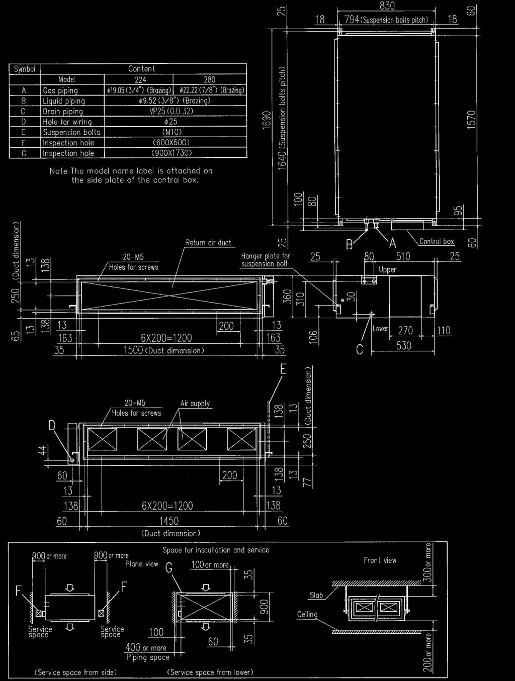


61 Dimensions ll measurements in mm. VIEW VIEW 61
62 R4 Duct Connected -Low/Middle Static Pressure- FDUM Model No. FDUM22KXE6F FDUM28KXE6F FDUM36KXE6F FDUM45KXE6F FDUM56KXE6F NEW FDUM71KXE6F FDUM90KXE6F FDUM112KXE6F FDUM140KXE6F FDUM160KXE6F Filter kit (option) UM-FL1EF : for 22~56 UM-FL2EF : for 71, 90 UM-FL3EF : for 112, 140, 160 Remote control (option) Wired Wireless Filter pressure loss:5pa * RC-EX1 RC-E5 RCH-E3 RCN-KIT3-E Improvement of the serviceability Thin design Specifications Item Nominal cooling capacity Nominal heating capacity Power source Power consumption Sound power level Sound pressure level Exterior dimensions H x W x D Net weight ir flow Model db() db() mm kg m3/min Maximum external static pressure Pa Outside air intake ir filter Remote control(option) Installation data Refrigerant piping size mm(in) Fan unit (impeller and motor) can be pulled out from the right side or the bottom side of the unit. Maintenance can be available from the right side or the bottom side. Maintenance hole Service space FDUM22KXE6F FDUM28KXE6F FDUM36KXE6F FDUM45KXE6F FDUM56KXE6F FDUM71KXE6F FDUM90KXE6F FDUM112KXE6F FDUM140KXE6F Unit Liquid line:ø6.35(1/4") Gas line:ø9.52(3/8") (mm) Pipe Fan unit Phase V, 50Hz Hi:32 Me:29 Lo:26 Hi:33 Me:29 Lo: Hi: Me:9 Lo:8 Hi:19 Me:15 Lo: Hi:38 Me:36 Lo:30 Hi:40 Me:34 Lo:29 Hi:40 Me:35 Lo: x 750 x x 950 x x 1370 x Possible Filter kit:um-fl1ef/um-fl2ef/um-fl3ef(option) wired:rc-ex1, RC-E5, RCH-E3 wireless:rcn-kit3-e Liquid line:ø6.35(1/4") Gas line:ø12.7(1/2") The height of all FDUM models is only 280mm Hi:28 Me:25 Lo:19 Hi:32 Me:26 Lo:20 Hi:35 Me:28 Lo:22 Liquid line:ø9.52(3/8") Gas line:ø15.88(5/8") FDUM160KXE6F The data are measured under the following conditions(iso-t1). : Indoor temp. of 27ºCDB, 19ºCWB, and outdoor temp. of 35ºCDB. : Indoor temp. of 20ºCDB, and outdoor temp. of 7ºCDB, 6ºCWB. External static pressure of indoor unit is 35Pa(22/28/36/45/56/71/90), 60Pa(112/140/160). 2. Sound pressure level indicates the value in an anechoic chamber. During operation these values are somewhat higher due to ambient conditions. Powerful-Hi can be selected. Sound pressure level: FDUM22/28/36/45/56 37dB(), FDUM71/90 38dB(), FDUM112 44dB(), FDUM140 45dB(), FDUM160 47dB(). ir flow: FDUM22/28/36/45/56 13m 3 /min, FDUM71/90 24m 3 /min, FDUM112 36m 3 /min, FDUM140 39m 3 /min, FDUM160 48m 3 /min. H 350 H mm less H 299 H 280 FDUM112/140KXE6F 19mm less FDUM22~90KXE6F 62


63 Dimensions ll measurements in mm. FDUM22KXE6F, 28KXE6F, 36KXE6F, 45KXE6F, 56KXE6F FDUM71KXE6F, 90KXE6F FDUM112KXE6F, 140KXE6F, 160KXE6F Round duct adapter In case of requirements of round duct adapter, please access the followings for details. Company tel IRZONE
64 R4 Duct Connected (thin) -Low Static Pressure- FDUT NEW NEW Model No. FDUT15KXE6F-E FDUT22KXE6F-E FDUT28KXE6F-E FDUT36KXE6F-E FDUT45KXE6F-E FDUT56KXE6F-E FDUT71KXE6F-E Expansion of lineup Remote control (option) Wired RC-EX1 RC-E5 RCH-E3 Wireless RCN-KIT3-E Current New 15KXE6F-E 22KXE6F-E 28KXE6F-E 36KXE6F-E 45KXE6F-E 56KXE6F-E 71KXE6F-E * (1) Can not be connected to some KX outdoor units. Please consult your dealer for further details. * (2) Regarding pipe length (150m or more is required) and temperature condition (the lowest is ºC) in the cooling operation etc., please refer to our technical manual. Duct kit and filter options Item Contents for FDUT15/22/28/36KXE6F-E for FDUT45/56KXE6F-E for FDUT71KXE6F-E Outlet duct plate 1 UT-ST1EF UT-ST2EF UT-ST3EF Filter set UT-FL1EF UT-FL2EF UT-FL3EF Filter pressure loss : 5 Pa 2 Filter fixing plate 1 Outlet duct plate Specifications Item Nominal cooling capacity Nominal heating capacity Power source Power consumption Sound power level Sound pressure level 1 Sound pressure level 2 Model db() db() db() Exterior dimensions H x W x D mm Net weight kg ir flow (Standard) m3/min External Static pressure Pa Outside air intake ir filter Remote control(option) Installation data Refrigerant piping size mm(in) FDUT15KXE6F-E Hi:28 Me:26 Lo:22 Hi:32 Me:29 Lo:25 FDUT22KXE6F-E Hi:28 Me:26 Lo:22 Hi:32 Me:29 Lo:26 200x750x500 FDUT28KXE6F-E FDUT36KXE6F-E FDUT45KXE6F-E FDUT56KXE6F-E FDUT71KXE6F-E Phase V, 50Hz Hi:33 Me:30 Lo:26 Hi:37 Me:34 Lo:28 Hi:34 Me:32 Lo:28 Hi:36 Me:33 Lo:27 200x950x500 Hi:35 Me:33 Lo:30 Hi:38 Me:33 Lo:29 Hi:35 Me:31 Lo:28 Hi:41 Me:37 Lo:32 220x1150x Hi:6 Me:5 Lo:4 Hi:7.5 Me:6 Lo:5 Hi:8.5 Me:7 Lo:5.5 Hi:11.5 Me:9 Lo:7 Hi:12.5 Me:9 Lo:7.2 Hi:16 Me:13 Lo:9.5 Standard:, Max:35 Standard:, Max:50 Not possible Filter set:ut-fl1ef/ut-fl2ef/ut-fl3ef(option) wired:rc-ex1, RC-E5, RCH-E3 wireless:rcn-kit3-e Liquid line:ø6.35(1/4") Gas line:ø9.52(3/8") Liquid line:ø6.35(1/4") Gas line:ø12.7(1/2") Liquid line:ø9.52(3/8") Gas line:ø15.88(5/8") 1. The data are measured under the following conditions(iso-t1). : Indoor temp. of 27ºCDB, 19ºCWB, and outdoor temp. of 35ºCDB. : Indoor temp. of 20ºCDB, and outdoor temp. of 7ºCDB, 6ºCWB. External static pressure of indoor unit is Pa. 2. The data of nominal cooling and heating capacity and sound pressure level are measured with Pa of external static pressure. 3. The sound level indicates the value of rear-intake type with duct in anechoic chamber. During operation these values are somewhat higher due to ambient conditions. 4. Sound pressure levels are values when 2m supply duct and 1m return duct are connected. 1 : Mike position is 1.5m below unit, 2 : Mike position is 1m in front and 1m below the air supply duct. 3 Filter 64


65 Dimensions ll measurements in mm. FDUT15KXE6F-E, 22KXE6F-E, 28KXE6F-E, 36KXE6F-E FDUT45KXE6F-E, 56KXE6F-E FDUT71KXE6F-E 65
66 Duct Connected (Compact & Flexible) FDUH Remote control (option) Wired Model No. FDUH22KXE6F FDUH28KXE6F FDUH36KXE6F Drain up kit (option) (600mm) UH-DU-E RC-EX1 RC-E5 Wireless RCN-KIT3-E RCH-E3 Filter kit (option) UH-FL1E Filter pressure loss:5pa * Compact and thin size, light weight Quiet operation Our leading high technology has realized the best solution for air conditioning in hotels with compact and thin size units and high energy efficiency. In addition, weight is only 20kg. 257 mm 570mm The lowest sound level in the industry can ensure comfortable stay and rest in hotels. 530mm Installation Flexibility Control box and drain piping can be installed on both side of the unit and air intake to the unit is available from bottom or back side. Our highest technology can satisfy diverse installation requirements. Control box Wired remote control RCH-E3 (option) Simple remote control Considering specialized usage in hotel rooms, control buttons are limited only to minimum required functions such as ON/OFF, mode, temperature setting and fan speed. It is really simple and easy to use. Specifications Drain piping Item Model FDUH22KXE6F FDUH28KXE6F FDUH36KXE6F Nominal cooling capacity Nominal heating capacity Power source Power consumption Sound power level db() Sound pressure level db() Exterior dimensions HxWxD mm Net weight kg ir flow m3/min External static pressure Pa Outside air intake ir filter Remote control(option) Installation data mm(in) Refrigerant piping size 1 Phase V, 50Hz HI: 33 Me: 30 Lo: x570x HI: 7 Me: 6.5 Lo: 6 30 Not possible Filter kit:uh-fl1e(option) wired:rc-ex1, RC-E5, RCH-E3 wireless:rcn-kit3-e Liquid line:ø6.35(1/4") Gas line:ø9.52(3/8") Liquid line:ø6.35(1/4") Gas line:ø12.7(1/2") 1. The data are measured under the following conditions(iso-t1). : Indoor temp. of 27ºCDB, 19ºCWB, and outdoor temp. of 35ºCDB. : Indoor temp. of 20ºCDB, and outdoor temp. of 7ºCDB, 6ºCWB. 2. Sound pressure level indicates the value in an anechoic chamber. During operation these values are somewhat higher due to ambient conditions. Powerful-Hi can be selected. Sound pressure level: FDUH22/28/36 39dB(). ir flow: FDUH22/28/36 8.5m 3 /min. 66
 Supply air duct Symbol B C1,C2 D E F C o n t e n t M o d e l FDUH22KXE6F,28KXE6F Gas piping ø9.52 (3/8\") (Flare) Liquid piping ø6.35 (1/4\") (Flare) Drain piping VP20(O.D.26) Hole for wiring Suspension bolts ø30 (M) Inspection hole (635X890) Note (3) FDUH36KXE6F ø12.")
 62.1 488 (Suspension bolts pitch) 530 C2 6 890 600 0 ir inlet (D) 68 21 Unit:mm 188.5 148.5 12-ø4 Holes for tapping screws 37.")
67 Dimensions ll measurements in mm ø4 Holes for tapping screws (Duct dimension) (Duct dimension) Supply air duct Symbol B C1,C2 D E F C o n t e n t M o d e l FDUH22KXE6F,28KXE6F Gas piping ø9.52 (3/8") (Flare) Liquid piping ø6.35 (1/4") (Flare) Drain piping VP20(O.D.26) Hole for wiring Suspension bolts ø30 (M) Inspection hole (635X890) Note (3) FDUH36KXE6F ø12.7 (1/2") (Flare) 30.8 C ir outlet Drain hose piece (Standard ccessory) (Installed on site) Note(4) (Suspension bolts pitch) Space for installation and service F 66 B Control box Note(4) (Suspension bolts pitch) 530 C ir inlet (D) Unit:mm ø4 Holes for tapping screws 37.6 D ir inlet E Notes ( 1 ) The model name label is attached on the fan case inside the air return grille. ( 2 ) When control box is located on the reverse side, Installation space should be modified to new location. ( 3 ) Contorl box and Drain hose piece are able to be relocated on the reverse side. G Bottom plate (ble to be located on the back side) View G In case of Bottom air intake ø4 Holes for tapping screws ir inlet Simple remote control View G (fter bottom plate is replaced to back side) 67
68 Wall Mounted FDK Remote control (option) Wired Model No. FDK22KXE6F FDK28KXE6F FDK36KXE6F FDK45KXE6F FDK56KXE6F FDK71KXE6F FDK22~56 RC-EX1 Wireless RC-E5 RCH-E3 RCN-K-E : FDK22~56 RCN-K71-E : FDK71 FDK71 Innovative Design Installation Workability New FDK models adopt the air flow design that's proven to minimise resistance in a CFD analysis to achieve uniform air conditioning to the furthest corners of the room. 259 The new slimmer design allows easy & neat installation even in tight spaces. Specifications lso included is a new easy clean mechanism where the front panel is opened/closed simply from the bottom to easily access the detachable filters. Item Model FDK22KXE6F FDK28KXE6F FDK36KXE6F FDK45KXE6F FDK56KXE6F FDK71KXE6F Nominal cooling capacity Nominal heating capacity Power source 1 Phase V, 50Hz Power consumption Sound power level Sound pressure level db() db() Exterior dimensions H x W x D mm Net weight kg ir flow m3/min Outside air intake ir filter, Q ty Remote control(option) Installation data Refrigerant piping size mm(in) Fast Slow Colors in the figure show the air speed. Flap control system Selection of flap position is possible. flap can be set at different angles. RCH-E3 is not applicable to the Flap control system. * Hi:35 Me:33 Lo:31 Hi:35 Me:33 Lo:31 Liquid line:ø6.35(1/4") Gas line:ø9.52(3/8") Upper position Movable range Lower position Hi:41 Me:35 Lo:31 Hi:39 Me:35 Lo:31 Improved Maintainability Hi:42 Me:37 Lo:33 Hi:42 Me:37 Lo:33 Liquid line:ø6.35(1/4") Gas line:ø12.7(1/2") Hi:46 Me:42 Lo:37 Hi:46 Me:42 Lo:37 Hi:47 Me:43 Lo:39 Hi:47 Me:43 Lo: x 840 x x 98 x Hi:8 Me:7 Lo:6 Hi: Me:9 Lo:7 Hi:11 Me:9 Lo:7 Hi:14 Me:12 Lo: Hi:21 Me:18 Lo:15 Not possible Polypropylene net x2 (Washable) wired:rc-ex1, RC-E5, RCH-E3 wireless:rcn-k-e (for FDK22~56), RCN-K71-E (for FDK71) Liquid line:ø9.52(3/8") Gas line:ø15.88(5/8") 1. The data are measured under the following conditions(iso-t1). : Indoor temp. of 27ºCDB, 19ºCWB, and outdoor temp. of 35ºCDB. : Indoor temp. of 20ºCDB, and outdoor temp. of 7ºCDB, 6ºCWB. 2. Sound pressure level indicates the value in an anechoic chamber. During operation these values are somewhat higher due to ambient conditions. Powerful-Hi can be selected. Sound pressure level: FDK22/28 38dB(), FDK36 48dB()()&42dB()(), FDK45 48dB()()&43dB()(), FDK56 48dB()()&47dB()(), FDK71 48dB(). ir flow: FDK22/28 11m 3 /min, FDK36/45 15m 3 /min, FDK56 16m 3 /min, FDK71 24m 3 /min. 68


69 Dimensions ll measurements in mm. FDK22KXE6F, 28KXE6F, 36KXE6F, 45KXE6F, 56KXE6F FDK71KXE6F 69
70 Ceiling Suspended FDE Model No. FDE36KXE6F FDE45KXE6F FDE56KXE6F FDE71KXE6F FDE112KXE6F FDE140KXE6F Small Light-weight Quiet Sleek, intelligent design Remote control (option) Wired RC-EX1 RC-E5 RCH-E3 Wireless RCN-E-E Flap control system Selection of flap position is possible. flap can be set at different angles. RCH-E3 is not applicable to * the Flap control system. Upper position Movable range Lower position New Slim Design 2mm Slim and sleek design starting at just 28kgs in weight means quick, easy & neat installation. Installation Workability Up Rear Right Specifications Item Model FDE36KXE6F FDE45KXE6F FDE56KXE6F FDE71KXE6F FDE112KXE6F FDE140KXE6F Nominal cooling capacity Nominal heating capacity Power source 1 Phase V, 50Hz Power consumption Sound power level Sound pressure level db() db() Exterior dimensions H x W x D mm Net weight kg ir flow m3/min Outside air intake ir filter, Q ty Remote control(option) Installation data Refrigerant piping size mm(in) Hi:39 Me:38 Lo:36 Hi:41 Me:39 Lo: Hi: Me:9 Lo:7 Hi:16 Me:14 Lo:12 Hi:26 Me:23 Lo:21 Not possible Pocket Plastic net x2 (Washable) wired:rc-ex1, RC-E5, RCH-E3 wireless:rcn-e-e Liquid line:ø6.35(1/4") Gas line:ø12.7(1/2") Refrigerant piping can be routed in three directions (rear, up, right) & drain piping in left or right directions, allowing free layout to meet installation conditions Hi:44 Me:41 Lo:39 2 x 70 x x 1320 x x 1620 x 690 Liquid line:ø9.52(3/8") Gas line:ø15.88(5/8") Hi:46 Me:44 Lo:43 Hi:29 Me:26 Lo:23 1. The data are measured under the following conditions(iso-t1). : Indoor temp. of 27ºCDB, 19ºCWB, and outdoor temp. of 35ºCDB. : Indoor temp. of 20ºCDB, and outdoor temp. of 7ºCDB, 6ºCWB. 2. Sound pressure level indicates the value in an anechoic chamber. During operation these values are somewhat higher due to ambient conditions. Powerful-Hi can be selected. Sound pressure level: FDE36/45/56 46dB(), FDE71 50dB(), FDE112 46dB(), FDE140 50dB(). ir flow: FDE36/45/56 11m3/min, FDE71 18m3/min, FDE112 28m3/min, FDE140 32m3/min. 70
 24 40 990 40 70 ir supply 173 2 5 215 290 (Suspension bolts pitch) 135 68 4 690 D 145 52 195 235 271 53 9 B C1,C2 8 27 Drain hose")
71 Dimensions ll measurements in mm. C1,C2 FDE36KXE6F, 45KXE6F, 56KXE6F (Suspension bolts pitch) ir supply (Suspension bolts pitch) D B C1,C Drain hose piece (ccessory, 0.3m) (Installed on site) Note) The slope of drain piping inside the unit must take decline of mm Symbol B C 1,2 D E F G Content Gas piping Liquid piping Drain piping Hole for suspension bolt Back cutout Top cutout Hole for drain piping (for left back) ø12.7 (1/2") (Flare) ø6.35 (1/4") (Flare) VP20 (O.D.26) (M or M8) PE cover Plate cover (Knock out) Space for installation and service Position of top cutout and back cutout Hole for drain piping (for left) C2 76 ir return grille C B 0 or more 300 or more 150 or more 5 or more Obstacle Make a space of 4000 or more between the units when installing more than one. F Right side cutout Remove the cutout using side cutter or similar tool. E G Note(1)The model name label is attached on the fan casing inside the air return grille. C1,C2 FDE71KXE6F 290 (Suspension bolts pitch) D (Suspension bolts pitch) ir supply B C1,C Drain hose piece (ccessory, 0.3m) (Installed on site) Note)The slope of drain piping inside the unit must take decline of mm Symbol Content Gas piping B Liquid piping C 1,2 Drain piping D Hole for suspension bolt E Back cutout F Top cutout G Hole for drain piping(for left back) ø15.88 (5/8") (Flare) ø9.52 (3/8") (Flare) VP20 (O.D.26) (M or M8) PE cover Plate cover (Knock out) Space for installation and service 20 Position of top cutout and back cutout Hole for drain piping (for left) C2 76 ir return grille C B 0 or more 300 or more 150 or more 5 or more Right side cutout F G E Obstacle Remove the cutout using side cutter or similar tool. Make a space of 4500 or more between the units when installing more than one. Note(1)The model name label is attached on the fan casing inside the air return grille. FDE112KXE6F, 140KXE6F 290 (Suspension bolts pitch) D C1,C (Suspension bolts pitch) ir supply B C1,C Drain hose piece (ccessory, 0.3m) (Installed on site) Note) The slope of drain piping inside the unit must take decline of mm Symbol B C1,2 D E F G Content Gas piping Liquid piping Drain piping Hole for suspension bolt Back cutout Top cutout Hole for drain piping (for left back) ø15.88 (5/8") (Flare) ø9.52 (3/8") (Flare) VP20 (O.D.26) (M or M8) PE cover Plate cover (Knock out) Space for installation and service Position of top cutout and back cutout Hole for drain piping (for left) C2 76 ir return grille C B 0 or more 300 or more 150 or more 5 or more Obstacle Make a space of 5000 or more between the units when installing more than one. F Right side cutout Remove the cutout using side cutter or similar tool. E G Note(1)The model name label is attached on the fan casing inside the air return grille. 71
72 Floor Standing -2way- FDFW Model No. FDFW28KXE6F FDFW45KXE6F FDFW56KXE6F Remote control (option) Wired Wireless RC-EX1 RC-E5 RCH-E3 RCN-FW-E Sophisticated Design With classy semi flat front panel in chic white, the new series fit in various kinds of rooms and create relaxing atmosphere. Choice of wall hanging, floor standing or behind gallery installation is available. Quiet Operation Thanks to optimum balance of air outlet direction and sufficient air flow volume, the sound level has been minimized. The level of FDFW28KXE6F in the cooling lo mode is 30dB() only. Flap control system Selection of flap position is possible. flap can be set at different angles. Movable range Upper position Convenient to use operation Simultaneous lower and upper air outlets or upper outlet can be selected by air flow direction button. Further control can be arranged by a remote control. RCH-E3 is not applicable to * the Flap control system. Lower position Specifications (In case of use of wireless remote control) Item Nominal cooling capacity Nominal heating capacity Power source Power consumption Sound power level Sound pressure level Model db() db() Exterior dimensions H x W x D mm Net weight kg ir flow (Standard) m3/min ir filter, Q ty Remote control(option) Installation data Refrigerant piping size mm(in) FDFW28KXE6F Hi:36 Me:34 Lo:30 19 Liquid line:ø6.35(1/4") Gas line:ø9.52(3/8") FDFW45KXE6F Phase V, 50Hz Hi:38 Me:36 Lo:33 600x860x Hi:9 Me:8 Lo:7 Polypropylene net x1 (Washable) wired:rc-ex1, RC-E5, RCH-E3 wireless:rcn-fw-e Liquid line:ø6.35(1/4") Gas line:ø12.7(1/2") FDFW56KXE6F Hi:44 Me:37 Lo:33 Hi:11 Me:9 Lo:8 1. The data are measured under the following conditions(iso-t1). : Indoor temp. of 27ºCDB, 19ºCWB, and outdoor temp. of 35ºCDB. : Indoor temp. of 20ºCDB, and outdoor temp. of 7ºCDB, 6ºCWB. 2. Sound pressure level indicates the value in an anechoic chamber. During operation these values are somewhat higher due to ambient conditions. 72


73 Dimensions ll measurements in mm. 73
74 R4 Floor Standing (with casing) FDFL Floor Standing (without casing) FDFU Model No. FDFL71KXE6F Remote control (option) Wired RC-EX1 RC-E5 RCH-E3 Wireless RCN-KIT3-E FDFU28KXE6F FDFU45KXE6F FDFU56KXE6F FDFU71KXE6F FDFL FDFU (concealed type) Compact design at 630mm height Wider airflow for optimum comfort Specifications Item Nominal cooling capacity Nominal heating capacity Power source Power consumption Sound power level Sound pressure level Model db() db() Exterior dimensions H x W x D mm Net weight kg ir flow (Standard) m3/min ir filter, Q ty Remote control(option) Installation data Refrigerant piping size mm(in) FDFL71KXE6F FDFU28KXE6F FDFU45KXE6F Phase V, 50Hz FDFU56KXE6F Hi:43 Me:41 Lo:40 Hi:41 Me:38 Lo:36 Hi:43 Me:41 Lo:40 630x1481x225 FDFU71KXE6F Hi:18 Me:15 Lo:12 Hi:12 Me:11 Lo: Hi:14 Me:12 Lo: Hi:18 Me:15 Lo:12 Polypropylene net x1 (Washable) wired:rc-ex1, RC-E5, RCH-E3 wireless:rcn-kit3-e Liquid line:ø9.52(3/8") Gas line:ø15.88(5/8") Liquid line:ø6.35(1/4") Gas line:ø9.52(3/8") 630x77x225 Liquid line:ø6.35(1/4") Gas line:ø12.7(1/2") 630x1362x225 Liquid line:ø9.52(3/8") Gas line:ø15.88(5/8") 1. The data are measured under the following conditions(iso-t1). : Indoor temp. of 27ºCDB, 19ºCWB, and outdoor temp. of 35ºCDB. : Indoor temp. of 20ºCDB, and outdoor temp. of 7ºCDB, 6ºCWB. 2. Sound pressure level indicates the value in an anechoic chamber. During operation these values are somewhat higher due to ambient conditions. 74


75 Dimensions ll measurements in mm. FDFL FDFU Dimension Table model FDFU28KXE6F, 45KXE6F, 56KXE6F FDFU71KXE6F Unit:mm a b c d e
76 R4 Outdoor ir Processing unit FDU-F Remote control (option) Wired Model No. FDU500FKXE6F FDU850FKXE6F FDU1300FKXE6F FDU1800FKXE6F RC-EX1 RC-E5 Wireless RCH-E3 Not available in EU/EE area. ir conditioning and intake of outdoor air are in the same system Fan control kit (option) (0~200Pa) U-FCRB RCN-KIT3-E Outdoor ir processing unit can be connected in a KX6 system as one of indoor unit series and can create fresh and comfortable air supply together from our high advanced technology. Outdoor ir Processing unit indoor unit air conditioning indoor unit outside air supply office KX6 outdoor unit refresh room, corridor rest room Compact design Compact design at just 360mm in height, high static pressure of 200Pa and the industry's lowest noise level can meet various kind of installation location for office, refresh room, restroom and kitchen of restaurant etc. exhaust air supply air outdoor air outdoor air supply air (1) This unit is the specific unit for processing the outdoor air temperature closer to the room temperature. For conditioning the room temperature a dedicated air-conditioner is required additionally. (2) This unit monitors the outdoor air temperature and controls thermostat ON/OFF at the setting temperature by the remote controller, which indicates the outdoor air temperature for controlling thermostat ON/OFF. When thermostat is turned OFF, the operation is changed to the fan mode so that unprocessed outdoor air will be blown into the room directly. Therefore place the air outlet port or orient the air outlet direction not to blow air directly to persons in the room, especially in the small room such as a restroom and/or sanitary hot water supplying room. (3) It is strictly prohibited to monitor the room temperature by switching to the thermistor at remote controller side and/or the optional remote thermistor. Otherwise dew formation at air outlet port and/or dew dripping may occur during cooling operation due to the lower outdoor air temperature. Therefore keep the remote controller of this unit in place closer to the administrator so as not to be touched it freely by the end user. (4) Dehumidifying operation with this unit is prohibited. (5) When handing over this unit to the end user, make sure to explain sufficiently about the foregoing cautions, the installation place and usage of remote control for this unit and the location of the air outlet. 76

77 Connectivity with KX6 series FDU-F series are connectable to 8~48HP KX6 outdoor units, not connectable to 4~6HP. 8 ~ 48 HP : Yes, 4 ~ 6 HP : No Combination with KX6 series B case In case O processing units only are connected with KX6 outdoor units In case both of O processing units and dedicated air-conditioner are connected with KX6 outdoor unit. Combination The total capacity of FDU-F is 50~0% of outdoor capacity and max quantity of FDU-F is 2 units. The total capacity of FDU-F and dedicated air-conditioners is 50~0% of outdoor capacity and max quantity of FDU-F should be below 30% of outdoor unit capacity. [ ] [ B ] Less than 30% FDU850FKXE6F FDU850FKXE6F FDU850FKXE6F HP (5HP) (5HP) 18HP (5HP) 6HP 6HP Concept (Difference between FDU-F and SF) SF is the energy recovery ventilation unit which can recover heat energy from exhaust air to supply air and "has no air processing function, but FDU-F is air processing unit which can treat the supply air closer to room temperature by cooling or heating in connection with KX6 refrigerant system and exhaust air is discharged to outside of the room. FDU-F O Processing units Outside ir Supply Exhaust ir Direct Expansion Heat Exchanger SF Outside ir Supply Exhaust ir 77
78 Specifications Item Nominal cooling capacity Nominal heating capacity Power source Power consumption Sound pressure level db() Exterior dimension HxWxD mm Net weight kg m3/min ir flow (Standard) m3/h External static pressure Pa ir filter, Q'ty Remote control(option) Installation data Refrigerating piping size Model mm (in) FDU500FKXE6F x820x Liquid line:ø9.52(3/8") Gas line:ø15.88(5/8") FDU850FKXE6F x1200x Phase V, 50Hz FDU1300FKXE6F Procure locally wired:rc-ex1, RC-E5, RCH-E3 wireless:rcn-kit3-e Liquid line:ø9.52(3/8") Gas line:ø19.05(3/4") 360x1570x830 FDU1800FKXE6F Liquid line:ø9.52(3/8") Gas line:ø22.22(7/8") 1. The data are measured at 33ºCDB 28ºCWB (68%RH) during cooling and 0ºCDB-2.9ºCWB (50%RH) during heating (no frost). External static pressure of indoor unit with optional fan controlling kit "U-FCRB" is 0Pa. 2. Temperature range of outdoor air must be 20~40ºCDB (32ºCWB) during cooling and -~24ºCDB during heating. 3. Operation sound is measured in an anechoic room based on JIS standard. In case of actual room installation, it usually becomes higher than the displayed value due to the surrounding noise and echo. 4. The total connection capacity of the other standard air conditioning units and the outdoor air processing units must be from 50% to 0% (the total includes the outdoor air processing unit). The connection capacity of the outdoor air processing unit must not exceed 30% of the capacity of the outdoor unit. 5. Single outdoor air processing unit can be used alone. The connection capacity of the outdoor air processing unit must be from 50% to 0% of the total capacity of the outdoor unit. 6. Single outdoor air processing unit can be used alone. Maximum number of outdoor air processing units that can be connected to the outdoor unit is 2units. 7. Values of sound pressure level become increased 5dB(), when external static pressure is 200Pa (factory setting). 8. Values of air flow volume are those at external static pressure 200Pa (factory setting). Dimensions ll measurements in mm. FDU500FKXE6F Suspension bolts pitch (Inner size of duct flange) Suspension bolts pitch 12-M5 screw Duct connection port for outdoor air inlet bove Control box 12-M5 screw Port for air outlet (Inner size of duct flange) or more (Inner size of duct flange) or more Plan view Installation space (Below suspension bolt pitch) Installation space or more Installation space Ceiling Service space or more Piping space (Service from side) (Service from below) (Service from side and below) Slab Below Front view or more or more (Inner size of duct flange) Symbol Content Gas piping Liquid piping Drain piping connection Power supply wiring connection Suspension bolt Inspection Opening Inspection Opening 78
79 FDU850FKXE6F Suspension bolts pitch (Inner size of duct flange) FDU1300FKXE6F, FDU1800FKXE6F Suspension bolts pitch Suspension bolts pitch Suspension bolts pitch 16-M5 screw Duct connection port for outdoor air inlet bove Control box 12-M5 screw Port for air outlet (Inner size of duct flange) or more Plan view or more Installation space (Inner size of duct flange) Installation space or more Installation space (Below suspension bolt pitch) Ceiling Service space or more (Service from side) Piping space (Service from below) (Service from side and below) Slab Front view Below or more or more (Inner size of duct flange) Symbol Content Gas piping Liquid piping Drain piping connection Power supply wiring connection Suspension bolt Inspection Opening Inspection Opening (Inner size of duct flange) 20-M5 screw Duct connection port for outdoor air inlet bove Control box 20-M5 screw Port for air outlet (Inner size of duct flange) or more (Inner size of duct flange) Installation space or more or more Installation space Plan view (Below suspension bolt pitch) Below Front view or more (Inner size of duct flange) Slab Ceiling Service space Service space or more Piping space (Service from side) (Service from below) (Service from side and below) or more Symbol Gas piping Liquid piping Drain piping connection Power supply wiring connection Suspension bolt Inspection Opening Inspection Opening Content 79
80 Capacity Fresh ir Ventilation and Heat Exchange unit SF-E6 Model No. SF150E6 SF250E6 SF350E6 SF500E6 SF650E6 SF800E6 SF00E6 Energy Performance of Building Directive - EPBD EPBD limit the amount of electrical/gas power to be used to provide heating or cooling in commercial buildings. Therefore the building designer needs to select energy efficient heating/cooling equipment, and to minimise energy losses through ventilation systems. The SF recovers heat energy which would otherwise be exhausted to atmosphere, and uses this energy to warm the air entering the building. The reverse happens in warmer climates, where the exhausted cool air is used to partially cool the incoming air. Capturing this waste energy, means the heating/ cooling requirements of the building are reduced, so smaller size plant can be selected, savings can be made in long term energy consumption, and carbon emissions are reduced. The inclusion of the SF energy recovery ventilation units in the building design, will reduce the total amount of carbon emissions. Increased external static pressure at UHi air flow Pa previous New 5 90 SF250E6 SF350E6 SF500E6 SF800E6 SF00E6 Specifications Item Model SF150E6 SF250E6 SF350E6 SF500E6 SF650E6 SF800E6 SF00E6 Power source 1 Phase V, 50Hz Exterior dimensions Height x Width x Depth mm 270x970x x882x x50x x90x x1204x x1322x x1322x1134 Exterior appearance Galvanized steel sheet Power input W Running current Enthalpy exchange UHi efficiency Temperature exchange efficiency 75 Enthalpy exchange Hi efficiency % Temperature exchange efficiency 75 Enthalpy exchange Lo efficiency Temperature exchange efficiency Motor & Q'ty W 20 x 2 20 x 2 40 x 2 70 x 2 0 x x x 2 ir handling equipment Fan type & Q ty Sirocco fan x 2 UHi ir flow Hi m 3 /h Lo UHi External static pressure Hi Pa Lo Net weight kg Remote control Included ir filter Supply air Exhaust air Protection for element (Washable) PS400 80
 R (Room ir) 27ºC ºC 33ºC 29ºC Outside ir Room ir Outside ir Room ir O (Outside ir) S (Supply ir) ºC 27ºC e.g.")
81 Structure (SF800E6) Heat exchanger element Damper Principle of operation (simple ventilation) FREE COOLING Principle of operation (heat exchanging) ENERGY RECOVERY Exhaust ir outdoor indoor Supply ir Exhaust ir outdoor indoor Supply ir E (Exhaust ir) R (Room ir) 27ºC ºC 33ºC 29ºC Outside ir Room ir Outside ir Room ir O (Outside ir) S (Supply ir) ºC 27ºC e.g. For cooling in winter time 35ºC 27ºC Dimensions ll measurements in mm. SF150E6, SF250E6, SF350E6, SF500E SF650E6, SF800E6, SF00E E (Exhaust ir) R (Room ir) E (Exhaust ir) R (Room ir) O (Outside ir) S (Supply ir) O (Outside ir) S (Supply ir) x 30 oblong hole pplied duct Model No. Nominal diameter SF150E6 ø0 SF250E SF350E6 ø150 SF500E6 ø200 Dimension table Unit:mm Model B C E F G H I J K L M N P SF150E ø98 ø SF250E ø144 ø164 SF350E ø SF500E ø194 ø x 30 oblong hole pplied duct Model No. Nominal diameter SF650E6 ø200 4 SF800E6 3 SF00E6 12 ø250 Dimension table Unit:mm Model B C E F G H I J K L M N P SF650E ø194 ø SF800E ø242 ø258 SF00E NO. Name Qt'y Frame 1 daptor 4 Terminal board 1 Inspection Cover 1 Fan 2 Motor 2 Heat Exchange Element SF150E6 SF250E6 SF350E6 SF500E6 SF650E6 SF800E6 SF00E Filter 2 9 Damper 1 Damper Motor Suspension fitting Electrical components box 4 1 Model SF350E6, SF500E6 and SF600E6 have different fan and motor locations. Installation reference Pipe hood O (Outside ir) Pipe hood Outer air intake duct E (Exhaust ir) Heat insulation material Outside intake duct ir supply duct Ceiling suspension bolt Room intake duct R (Room ir) S (Supply ir) Inside supply opening (Supply/exhaust air grill) Room intake opening (Supply/exhaust air grill) Note:n inspection port is needed for cleaning the heat exchanger and filter 1 or 2 times a year. 81
82 R4 Fresh ir DX ssembly Drain up kit (option, built-in type) (600mm) DX-DU-E Remote control (option) Wired RC-EX1 RC-E5 RCH-E3 Model No. SF-DX250E6 SF-DX350E6 SF-DX500E6 SF-DX800E6 SF-DX00E6 Wireless RCN-KIT3-E SF-DX is a heating or cooling coil incorporating MHI KX6 series controls. It can be used in combination with our SF series of total heat exchanger. Combination of SF-DX together with other KX6/KXR6 indoor units is possible. The capacity code index of each model is shown below and must be used when making the system selection. Total capacity code index must be within 0% of outdoor unit capacity code index. Remote control option is the same as with other KX6/KXR6 indoor units (see above). Connection to all superlink controls is also possible. Optional condensate lift mechanism is also available (600mm height). Return air temp. control or supply air temp. control can be selectable. O (Outside ir) E (Exhaust ir) Total heat exchanger Return / fresh air temp.sensor R (Room ir) SF-DX Supply / fresh air temp. sensor S or cooling coil (Supply ir) SF-DX can provide heating or cooling to the fresh air supplied through a 3rd party air handling unit or total heat exchanger such as our SF series. Specifications Item Model SF-DX250E6 SF-DX350E6 Nominal cooling capacity *1 Nominal heating capacity *2 Capacity code Power source Power consumption Running current Exterior dimensions H x W x D Net weight ir flow (Standard) Internal resistance Remote control(option) W mm kg m3/h Pa Installation data Refrigerant piping size mm(in) SF-DX500E6 SF-DX800E6 SF-DX00E Phase V, 50Hz wired: RC-E5, RCH-E3 wireless: RCN-KIT3-E Liquid line:ø6.35(1/4") Gas line:ø9.52(3/8") (1) The data are measured at the following conditions. Item Return/fresh air temperature Outdoor air temperature Standards Operation DB WB DB WB *1 27ºC 19ºC 35ºC 24ºC ISO-T1 *2 20ºC 7ºC 6ºC (2) This air-conditioner is manufactured and tested in conformity with ISO-T1 "UNITRY IR-CONDITIONERS". 315 x 452 x x 537 x x 682 x x 822 x 422 Liquid line:ø6.35(1/4") Gas line:ø12.7(1/2") Liquid line:ø9.52(3/8") Gas line:ø15.88(5/8") 82


83 Dimensions ll measurements in mm. SF-DX250E6,350E6 SF-DX500E6 SF-DX800E6 SF-DX00E6 83
84 eco touch REMOTE CONTROL(option) dvanced touch screen panel with full dot Liquid Crystal display User friendly LCD panel with light tap operation introduced as the industry's first Simple interface with only three buttons High level of visibility Big LCD with 3.8 inch full dot display Back light function Multi language display (9 languages) Run / Stop High power operation The highest capacity operation (Max 15 minutes) Increasing compressor speed Increasing air flow volume Energy-saving operation Changes set temperature. t 28ºC in cooling mode and 22ºC in heating mode, 25ºC in auto mode. Operation correction by outdoor temperature Simple setting by tapping button only 84


85 1. Basic operation ll settings done by tapping touch screen panel Operation mode Operation mode setting screen Dry Fan uto Setting temperature screen The desired operation mode can be selected by simply tapping this button. 2. Main functions Saving energy Sleep timer Peak cut timer utomatic temperature set back Weekly timer Set ON/OFF timer by hour Set ON/OFF timer by clock Convenience Comfort Individual flap control High power operation External ventilation ON/OFF Warming up operation utomatic fan speed Temperature increment setting by 0.5ºC Service LCD contrast setting Error code display Back light setting Operation data display Filter sign Next service date display Control sound Contact company display Outdoor silent mode USB connection (mini-b) Summer time setting Home leave mode Indoor & outdoor temperature display standby display Defrosting operation display uto cooling/heating display ºC/ºF display dministrator settings Room name setting You can select the temperature as desired by tapping button. eco touch Remote control RC-EX1 Series Utility Software By connecting this system to the eco touch Remote Control, the eco touch Remote Control can be operated from PC. and remote control settings can be programmed by PC and uploaded to controller via USB. Outdoor unit eco touch Remote Control USB eco touch Remote Control RC-EX1 Utility Software 85
86 R4 Control Systems <Individual control> Remote Control line up (except SF) indoor unit remote control RC-EX1 wired all models RC-E5 RCH-E3 indoor unit FDT wireless FDTC FDTW remote control indoor unit RCN-T-36W-E FDTS RCN-TC-24W-ER FDK22~56 RCN-TW-E FDK71 remote control RCN-TS-E indoor unit FDE remote control RCN-E-E RCN-K-E RCN-K71-E FDFW others* RCN-FW-E RCN-KIT3-E *FDTQ, FDU, FDUM, FDUT, FDUH, FDU-F Wired remote control with weekly timer (option) RC-E5 Weekly timer function as standard RC-E5 provides (as a standard feature) a weekly timer, which allows one-week operation schedules to be registered. user can specify up to four times a day to start/stop the air conditioner. (Temperature setting is also possible with the timer). Timer operation The RC-E5 controller enables extensive access to service and maintenance technical data combined with easy to use functions and a clear LCD display. Run hour meters to facilitate maintenance checking RC-E5 stores operation data when an anomaly occurs and indicates the error on the LCD. It also displays cumulative operation hours of the air conditioner and compressor since commissioning. Room temperature controlled by the remote control sensor The temperature sensor is housed in the top section of the remote control unit. This arrangement has improved the sensitivity of the remote control unit s sensor, which permits more finely controlled air conditioning. Changeable set temperature ranges RC-E5 allows the upper and lower limits of a set temperature range to be specified separately. By adjusting a set temperature range, you can ensure energy saving air conditioning by avoiding excessive cooling or heating. Upper limit Lower limit Changeable range 20~30ºC(effective for heating operation) 18~26ºC(effective for non-heating operation) Simple remote control (option) RCH-E3 (wired) Considering specialized usage in hotel rooms, control buttons are limited only to minimum required functions such as ON/OFF, mode, temperature setting and fan speed. It is really simple and easy to use. Up to 16 units It can control up to 16 units individually, with pressing the IR CON No. button. UTO restart This function allows starting the air conditioner automatically when power supply is restored after power failure or by turning on the power switch. RCH-E3 is not applicable to the Individual flap control system and the Flap control system. When RCH-E3 is used, the fan speed setting can only be set to 3 speed settings (Hi-Me-Lo). * Thermistor (option) SC-THB-E3 In case sensor in the indoor units or the remote control sensor can not sense the room temperature correctly, or individual remote control in each room is not required but only sensor is required (as when center control system is in place), install SC- THB-E3 at proper place in the rooms. 8m Wireless remote control (option) For wireless control simply insert the infra-red receiver kit on a corner of the panel RCN-T-36W-E, RCN-TC-24W-ER RCN-TW-E RCN-TS-E RCN-K-E, RCN-K71-E RCN-E-E RCN-FW-E RCN-KIT3-E The wireless remote control is not applicable to the Individual flap control system and the Flap control system. When the wireless remote control is used, the fan speed setting can only be set to 3 speed settings (Hi-Me-Lo). * 86


87 <Control System> SUPERLINK- MHI has now combined simplicity of installation with our highly sophisticated Superlink- control system, to offer building owners and occupiers a comprehensive control and management system, while providing complete commissioning and service maintenance assistance for installers and service engineers. The Superlink- network utilises two wire, non-polar cable - for further details of wiring. Superlink- is an advanced high speed data transmission system that can connect up to 128 indoor units and 32 outdoor units as a network. MHI offers a wide range of control options for the Superlink- network to suit any application large or small, as well as connection to new or existing building management systems. Individual MHI split systems can also be integrated on to the Superlink- network using SC-DN-E. Multi-KX6 outdoor units "Micro KX" Multi-KX6 indoor units Center Control SC-SL2N-E Capable of control and monitoring up to 64 indoor units. ll operational functions, plus enable/disable connected remote control. Individual On/Off Control KX6 Outdoor units Multi-KX6 indoor units SC-WGWN-/B PC Control Interface KX6 twined Outdoor units Center Control SC-SL4-E/BE Multi-KX6 indoor units with individual room control Center Control SC-SL1N-E 3-core + earth cable for connecting indoor and outdoor units 3-core cable for connecting indoor and outdoor units 3-core cable for connecting indoor and outdoor units 3-core + earth cable for connecting indoor and outdoor units Wireless remote control SRK/SRF-ZJXseries SC-BIKN-E SC-DN-E SC-DN-E SC-DN-E SC-DN-E One-to-one Wireless 87
88 R4 <Central Control> SC-SL1N-E Start/stop control of up to 16 indoor units either individually or collectively. Simple centralised control. 1. The SC-SL1N-E is connected to the Superlink- network via 2-core, non-polar wires ( B connection). 2. It will monitor and control the start/stop function of up to 16 units, with the sixteen operation button. 3. The unit or group numbers in operation or in need of service are displayed with an LED. 4. Collective start/stop is also available through the simultaneous on/off button. 5. Up to 12 SC-SL1N-E units can be connected to a Superlink- network (consisting of up to 128 indoor units). 6. If a power failure occurs, the SC-SL1N-E will resume the operation of the system according to a stored operation condition, once power is restored. SC-SL2N-E Central control of up to 64 indoor units including weekly timer function as standard. 1. The SC-SL2N-E is connected to the Superlink- network via 2-core, non-polar wires ( B connection). 2. It will monitor and control the start/stop function of up to16 units, or 16 groups of units, with the sixteen operation buttons. 3. It also monitors and controls the following functions for individual units, groups of units or the complete network: operation mode, set point temperature, return air temperature, louvre position, error code. ir flow and center lock function. 4. The unit or group numbers in operation or in need of service are displayed with an LCD. 5. Collective start/stop is also available through the simultaneous on/off button. 6. If a power failure occurs, the SC-SL2N-E will resume the operation of the system according to a stored operation condition, once power is restored. 7. The SC-SL2N-E can be connected to an external timer to facilitate timed on/off cycles. 8. The number of units connected to one network are detailed on the table below. Example of control by a centre control SC-SL2N-E SL1N-E SC-GIFN-E pplicable products Ventilation fan, ir purifier By using SC-GIFN-E together with central control such as SC-SL1N-E, SC-SL2N-E and SC-SL4-E/BE, you can start-stop, operate & monitor the operation of applicable products. Printed board Interface kit SW1 SW2 SW3 ten's place one's place hundred's place NEW ddress setting switch Set address number will be the address for SC-SL1N-E, SC-SL2N-E, SC-SL4-E/BE Terminal block 51X 52 52R B Net work communication line C V To & B terminal block on SC-SL1N-E, nomalous signal input SC-SL2N-E, SC-SL4-E/BE Operation signal input Net work Start-Stop command output n SC-SL2N-E performs the start/stop control, monitoring and mode setting of up to 64 units. It is a high quality air conditioner control system that allows up to 64 indoor units to be freely grouped into 1 to 16 groups. It allows not only the start/stop control but also the monitoring, display of operation statuses such as in operation or in need of service and mode setting such as switching of operation modes of connected units collectively, by group or individually. Outer dimensions: H120 x W215 x D25+35*mm. 35* is the measurement including the part contained in a recess. Note:Please consult dealer for combination of center controls and BMS interface units. 88

 Mode Today's schedule Group definition Set temperature Set temperature Special day")
89 SC-SL4-E/BE MHI introduces the full colour touch screen central control SC-SL4-E/BE, with 9 inch interactive LCD display. Offers control, monitoring, scheduling and service/maintenance functions for up to 128 indoor units. Control with PC is available by use of internet explorer. 128 units s can be controlled, scheduled, monitored and interrogated either individually, as groups or as blocks of groups with the following functions: Control Monitoring Scheduling dministration/service Run/Stop Operating state Yearly schedule Block definition Mode (cool/heat/fan/dry/uto) Mode Today's schedule Group definition Set temperature Set temperature Special day schedule Unit definition Operation permitted/prohibited Room temperature Time and date setting Fan speeds Operation permitted/ prohibited larm history ir direction Fan speed Energy consumption calculation period Filter sign reset ir direction Energy consumption cumulative operation time Demand control (3 steps) Emergency stop Filter sign Maintenance (1, 2 or back-up) Demand control Ethernet BSE-T/ 0BSE-TX Internet Explorer HUB Collective option output Collective stop signal input Watt-hour meter pulse input Electric power calculation function: (for SC-SL4-BE only) Item Model SC-SL4-E/SC-SL4-BE SC-SL4-BE gives outputs as electric power consumption h data -each indoor unit, each group, each SUPERLINK- system and each power pulse system- and uses USB memory. Method of data export Calculation software ir-conditioner power proportional distribution pulse input (Maximum) Connecting indoor units number (Maximum) SC-SL4-BE USB / LN Standard mbient temperature during use Power supply Power consumption External dimensions (Height x Width x Depth) Net weight Number of connectable units (indoor units) LCD touch panel SL (Superlink) signal inputs Watt-hour meter pulse input* Outputs Inputs Emergency stop signal input* Demand signal input* Operation output Error output 0 ~ 40 o C 1 Phase 0-240V 50/60Hz 18W 172mm x 250mm x 23 (+70) mm 2.0kg up to 128 units Colour LCD, 9 inches wide 1 systems (Super link- ) 8-point pulse width 0ms or more 1 point non-voltage a contact input continuous input (closed, forced stop) 2 point non-voltage a contact input continuous input (closed, demand control) 1 point maximum rated current 40m, 24 V During full stop; Open. If even one unit is operating; Closed 1 point maximum rated current 40m, 24 V Normal; closed. If even one unit is abnormal; Open * The receiving side power supply is DC 12V (m). The air conditioning charges calculations of this unit are based on OIML, the international standard. 89
90 R4 <PC windows central control> SC-WGWNB-/SC-WGWNB-B (Web gateway) (SC-WGWNB-B is with electric power calculation function) Control and monitoring of up to 96 cells (some cells can have two or more indoor units and total number of indoor units can be up to 128 units) centralised to a network PC using the Superlink- web gateway. Simple installation is assured with no special software requirements, operation is via Internet Explorer. low power embedded CPU and compact flash ROM ensure a large storage capacity with high reliability (no moving parts such as a PC fan, etc). n IP address filter function combined with three-level user authentication check also ensures security. Internet Explorer HUB Ethernet BSE-T/ 0BSE-TX pulse Watt meter pulse input P1 P2 P3 P4 (in case of SC-WGWNB-B) 48 cells 48 cells SC-DN-E <BMS interface unit> SC-BGWN-, SC-BGWN-B (BCnet gateway) 48 cells SUPERLINK- SUPERLINK- 64 units 64 units No. 1 system No. 2 system (SC-BGWN-B is with electric power calculation function) Cell SUPERLINK- No. 1 system 64 units Production by order SC-BGWN-/B is an interface device that converts MHI s Superlink- communication data to BCnet code. Control and monitoring functions of the a/c system for up to 96 cells (some cells can have two or more indoor units and total number of indoor units can be up to 128 units) can be integrated to a central control point via the building management system network. dditional engineering service cost etc. is required. Please consult your dealer when using this central control. PC requirements: Windows XP or Windows Vista or Windows 7. Monitor resolution 24 x 768. Web browser requirements: Internet Explorer 6.0 or 7.0. Production by order Ethernet BSE-T/0BSE-TX BCnet I/P Protocol. Network for lighting Emergency sensor network pulse Watt meter pulse input P1 P2 P3 P4 (in case of SC-BGWN-B) 48 cells SC-DN-E SUPERLINK- 64 units No. 2 system Cell dditional engineering service cost etc. is required. In case of SC-BGWN-B, communication test by qualified person regarding electric cost calculation function is required before commissioning. Please consult your dealer when using this gateway. SC-LGWN- (LonWorks gateway) SC-LGWN- is an interface device that converts MHI s Superlink- communication data to LonWorks code. Control and monitoring functions of the a/c system for up to 96 indoor units can be integrated to a central control point via the building management system network. SUPERLINK- No. 1 system 48 units Production by order LonWorks network (FTT-) Network for lighting Emergency sensor network SC-DN-E SUPERLINK- No. 2 system 48 units dditional engineering service cost etc. is required. Please consult your dealer when using this gateway. 90


91 Service/maintenance and monitoring The design of the outdoor units separates the air flow compartment from the mechanical compartment, allowing easy access to serviceable parts by simply removing the panel. ir flow chamber This design also means that the base plate of the air flow compartment acts as a drain tray connected to a drain pipe that runs through the mechanical compartment, so a simple connection of a drain hose to the base of the unit is all that is required, no need for a separate drain tray to be installed. Mechanical chamber Service maintenance and trouble shooting tasks can be carried out easily via the wired remote controller, as well as a cooling test operation to assist commissioning. The outdoor unit control box is also equipped with a switch to invoke a 'test-run' mode. This function can be used to help detect any installation errors, indoor/outdoor unit matching errors, EEV and valve operation. 'pump-down' switch on the PCB allows refrigerant to be recovered with the compressor protected. ll outdoor unit PCBs are also equipped with a 7-segment digital display for detailed operation history and fault finding. Operation data is stored for the 30 minute period preceding a fault occurring and details are displayed on the 7-segment reading. Outdoor unit PCB 7-segment display utomatically produced test-run report Operation data storage during servicing 6 Operation data storage when a fault occurs Method of connecting Mente PC in the combination Multi system Indoor unit Indoor unit Indoor unit Indoor unit Indoor unit Indoor unit 91
 will be provided by Intesis as it is an Intesis product. Product sales and delivery will be conducted by Intesis as well.")
 MH-C-KNX-128 (Max 128 indoor units / Superlink II) TOUCH SCREEN lams Windows blinds")
92 INTESIS BMS Interface for MHI air conditioners ll technical support, including specifying work, compatibility issues, product quality (repair and replacement issues), product liability issues and the required after sales service (including spare parts supply) will be provided by Intesis as it is an Intesis product. Product sales and delivery will be conducted by Intesis as well. For details concerning such matters please directly contact Intesis. Integration of MHI KX in your KNX installation by Superlink MH-C-KNX-48 (Max 48 indoor units / Superlink I & II) MH-C-KNX-128 (Max 128 indoor units / Superlink II) TOUCH SCREEN lams Windows blinds Lighting Energy management HVC INTEGRTED GTEWY Bidirectional: Supervision and Control Robust and reliable hardware Direct connection to KNX TP-1 BUS Independent management of communications Power supply: 230 VC 50/60Hz Wall mounting case Integration of MHI KX in your Modbus installation by Superlink MH-C-MBS-48 (Max 48 indoor units / Superlink I & II) MH-C-MBS-128 (Max 128 indoor units / Superlink II) MODBUS INTEGRTED GTEWY Bidirectional: Supervision and Control Robust and reliable hardware Modbus TCP or Modbus RTU RS-485/RS-232 Independent management of communications Power supply: 230 VC 50/60Hz Wall mounting case 92

93 Integration of MHI PC in your KNX installation by Remote control line MH-RC-KNX-1i Example : Device as Master TOUCH SCREEN Example : Device as Slave TOUCH SCREEN Windows blinds Energy management Windows blinds Energy management RC-E5 Protocol : KNX TP-1 bus Dimension : 71 x 71 x 27 mm External Power supply : no need lams Lighting HVC lams Lighting HVC Integration of MHI PC in your Modbus installation by Remote control line MH-RC-MBS-1 Example : Device as Master MODBUS Example : Device as Slave MODBUS Protocol : Modbus RTU (RS-485) Dimension : 93 x 53 x 58 mm External Power supply : no need RC-E5 Integration of MHI PC in your EnOcean installation by Remote control line MH-RC-ENO-1i/1iC Example : Device as Master Example : Device as Slave RC-E5 Protocol : EnOcean 1i : 868MHz@EU 1iC : 315MHz@US, SI Dimension : 0 x 70 x 28 mm External Power supply : no need Please access the followings for details. URL tel info@intesis.com
94 R4 Outdoor units High Head series (90m) 14~48hp (40.0~136.0) Model No. FDCH335KXE6-K FDCH400KXE6 FDCH450KXE6 FDCH504KXE6 FDCH560KXE6 FDCH560KXE6-K FDCH615KXE6 FDCH680KXE6 Nominal Capacity FDCH335KXE6-K & FDCH560KXE6-K are only used for combining with other models. Maximum allowable height difference between the outdoor and the indoor unit located at the lowest height position has been increased from 50m to 90m. (When the outdoor unit is located at higher position than the indoor unit) Blue Fin Model No. FDCH735KXE6 (FDCH335-K+FDCH400) FDCH800KXE6 (FDCH400x2) FDCH850KXE6 (FDCH400+FDCH450) FDCH900KXE6 (FDCH450x2) FDCH960KXE6 (FDCH450+FDCH504) FDCHKXE6 (FDCH504x2) FDCH65KXE6 (FDCH504+FDCH560) FDCH1130KXE6 (FDCH560x2) FDCH1180KXE6 (FDCH560-K+FDCH615) FDCH1235KXE6 (FDCH615x2) FDCH1300KXE6 (FDCH615+FDCH680) FDCH1360KXE6 (FDCH680x2) Production by order Nominal Capacity Blue Fin FDCH335KXE6-K FDCH400KXE6 FDCH450KXE6 FDCH504~680KXE6 Total length: 00m * 1 Max: m Outdoor unit Max height difference: 0.4m Range of operation To the first branch: max 130m From the first branch to the furthest indoor unit: 90m * 2 Max: 5m Height difference 50~90m * 3 Max height difference between indoor units: 15m Furthest indoor unit : 160m ºC +43ºC +15.5ºC -5ºC * 1 Select the total pipe length depending on the connectable capacity of indoor units. Connectable capacity % 130% Outdoor units' capacity = Max. connectable capacity of indoor units (%) 400~ % 504~ % ~ % * 2 * 3 The difference between the longest and shortest indoor unit piping from the first branch must be within 40m. In case of less than 50m, the High Head models can not be applied. In case is higher than outdoor unit, the High Head models can not be applied. 0% 300 m 5 m 00 m Total pipe length 94
95 Specifications Item Nominal horse power Power source Nominal capacity Electrical characteristics Exterior dimensions Net weight Refrigerant charge Sound pressure level Refrigerant piping size Starting current Power consumption Running current HxWxD Capacity connection Number of connectable indoor units R4 / Liquid line Gas line Model mm kg kg db() FDCH400KXE6 14HP x1350x FDCH450KXE6 16HP FDCH504KXE6 FDCH560KXE6 18HP 20HP 3 Phase V, 50Hz x1350x720 FDCH615KXE6 22HP / / / / / 64.5 ø12.7(1/2") ø15.88(5/8") mm(in) ø25.4(1") [ø28.58(1 1/8")] ø28.58(1 1/8") ø28.58(1 1/8") % 50~150 50~ FDCH680KXE6 24HP / Item Combination (FDCH) Nominal horse power Power source Nominal capacity Electrical characteristics Exterior dimensions Net weight Refrigerant charge Refrigerant piping size Capacity connection Number of connectable indoor units Starting current Power consumption Running current HxWxD R4 Liquid line Gas line Model mm kg kg mm(in) % FDCH735KXE6 FDCH800KXE6 FDCH850KXE6 FDCH900KXE6 335KXE6-K 400KXE6 400KXE6 450KXE6 400KXE6 400KXE6 450KXE6 450KXE6 26HP 28HP 30HP 32HP 3 Phase V, 50Hz x2700x x2 11.5x2 ø19.05(3/4") ø31.8(1 1/4") [ø34.92(1 3/8")] 50~ Item Combination (FDCH) Nominal horse power Power source Nominal capacity Electrical characteristics Exterior dimensions Net weight Refrigerant charge Refrigerant piping size Capacity connection Number of connectable indoor units Starting current Power consumption Running current HxWxD R4 Liquid line Gas line Model mm kg kg mm(in) % FDCH960KXE6 FDCHKXE6 FDCH65KXE6 FDCH1130KXE6 450KXE6 504KXE6 504KXE6 560KXE6 504KXE6 504KXE6 560KXE6 560KXE6 34HP 36HP 38HP 40HP 3 Phase V, 50Hz ø19.05(3/4") ø31.8(1 1/4")[ø34.92(1 3/8")] 50~ x2700x x x2 50~ ø22.22(7/8") ø38.1(1 1/2") Item Combination (FDCH) Nominal horse power Power source Nominal capacity Electrical characteristics Exterior dimensions Net weight Refrigerant charge Refrigerant piping size Capacity connection Number of connectable indoor units Starting current Power consumption Running current HxWxD R4 Liquid line Gas line Model mm kg kg mm(in) % FDCH1180KXE6 560KXE6-K 615KXE6 42HP FDCH1235KXE6 615KXE6 615KXE6 44HP Phase V, 50Hz x2700x x2 11.5x2 ø22.22(7/8") ø38.1(1 1/2") 50~130 FDCH1300KXE6 615KXE6 680KXE6 46HP FDCH1360KXE6 680KXE6 680KXE6 48HP The data are measured under the following conditions(iso-t1). : Indoor temp. of 27ºCDB, 19ºCWB, and outdoor temp. of 35ºCDB. : Indoor temp. of 20ºCDB, and outdoor temp. of 7ºCDB, 6ºCWB. Piping length is 7.5m. 2. Sound pressure level indicates the value in an anechoic chamber. During operation these values are somewhat higher due to ambient conditions. 3. [ ] : Pipe sizes applicable to European installations are shown in parentheses
96 R4 Dimensions ll measurements in mm. FDCH335KXE6-K, 400KXE6, 450KXE6 Mark Content 335-K Installation example Refrigerant gas piping connection pipe ø25.4(brazing) ø28.58(brazing) Dimensions 1 2 B C Refrigerant liquid piping connection pipe Refrigerant piping exit hole ø12.7(flare) ø88(or ø0) L1 L2 500 Open D F G H K L Power supply entry hole nchor bolt hole Drain waste water hose hole Drain hole Refrigerant oil equalization piping connection pipe Carrying in or hole for hanging ø50 (right. left. front), long hole 40 x 80 (under side) M x 4 places ø45 x 3 places ø20 x places ø9.52(flare) 230 x 60 L3 L4 H1 H2 H3 H No limited 00 No limited 0 Open No limited No limited Notes: (1) The unit must be fixed with anchor bolts. (2) Leave a 2m or larger space above the unit. (3) The unit name plate is attached on the lower right corner of the front panel. (4) The ports for refrigerant pipe and power cable penetrations are covered with half-blanks. Please cut off a half-blank with nippers in using these ports. (5) Use a ø88 port for refrigerant pipe connection. (6) nchor holes marked L J (four holes for M) are for a renewal installation. (7) The oil-equalising pipe K should be used when outdoor units are used in combination. (For 14,16Hp only) When more than one unit is installed Wall height H2 Wall height H3 L3 L2 L5 L6 L4 L1 (Unit front side) Wall height H2 Wall height H4 Installation example Dimensions L1 L2 L3 L4 L5 L6 H B Open Open No restrictions H2 H3 H4 No restrictions 00 No restrictions No restrictions No restrictions No restrictions 96
97 Dimensions ll measurements in mm. FDCH504KXE6, 560KXE6, 560KXE6-K, 615KXE6, 680KXE6 Mark Content Installation example Refrigerant gas piping connection pipe ø28.58(brazing) Dimensions 1 2 B Refrigerant liquid piping connection pipe ø12.7(flare) L1 500 Open C Refrigerant piping exit hole ø88(or ø0) L2 D Power supply entry hole ø50 (right. left. front), long hole 40 x 80 (under side) L3 0 0 F nchor bolt hole M x 4 places L4 Open G Drain waste water hose hole ø45 x 3 places H H Drain hole ø20 x places H2 No limited No limited K Refrigerant oil equalization piping connection pipe ø9.52(flare) H3 00 No limited L Carrying in or hole for hanging 230 x 60 H4 No limited Notes: (1) The unit must be fixed with anchor bolts. (2) Leave a 2m or larger space above the unit. (3) The unit name plate is attached on the lower right corner of the front panel. (4) The ports for refrigerant pipe and power cable penetrations are covered with half-blanks. Please cut off a half-blank with nippers in using these ports. (5) Use a ø88 port for refrigerant pipe connection. (6) nchor holes marked L J (four holes for M) are for a renewal installation. (7) The oil-equalising pipe K should be used when outdoor units are used in combination. 97
98 Refresh KX outdoor units If replacing a used unit with a new one, Refresh KX can reuse existing piping. Model No. FDCR224KXE6 FDCR280KXE6 <Option> FDCR-V-KIT-E : Service valve kit Nominal Capacity pplies to a wide range of pipe sizes (R22, R407C, R4 standard size). Meets to a short period of renewal installation. Savings on replacement expenses such as scrapping waste material or procuring new pipe. Possible to replace the existing unit with a new larger capacity unit. Possible to replace plural systems with one system. For example:existing 5HP x 2units can be replaced with a new HP x 1unit. 5HP x 2 HP x 1 Total length: 5m To the first branch: max 130m Outdoor unit Height difference 50m(outdoor unit above) 40m(outdoor unit below) Range of operation +43ºC From the first branch to the furthest indoor unit: 90m Furthest indoor unit: 160m Max height difference between indoor units: 15m ºC -15ºC -20ºC Specifications Item Nominal horse power Power source Nominal capacity Electrical characteristics Exterior dimensions Net weight Refrigerant charge Sound pressure level Refrigerant piping size Starting current Power consumption Running current HxWxD R4 / Liquid line Gas line Capacity connection Number of connectable indoor units Model mm kg kg db() mm(in) % FDCR224KXE6 8HP 1. The data are measured under the following conditions(iso-t1). : Indoor temp. of 27ºCDB, 19ºCWB, and outdoor temp. of 35ºCDB. : Indoor temp. of 20ºCDB, and outdoor temp. of 7ºCDB, 6ºCWB. 2. Sound pressure level indicates the value in an anechoic chamber. During operation these values are somewhat higher due to ambient conditions /58 ø19.05( 3 /4")~ø25.4(1") 13 3 Phase V, 50Hz x80x ø9.52( 3 /8")~ø15.88( 5 /8") 50~130 FDCR280KXE6 HP /60 ø22.22( 7 /8")~ø28.58(1 1 /8") 16 98


 remove the pipe refresh kit after cleaning the used pipe Pipe refresh kit (FDCR-KIT-E) Mark B C D E F1 F2 F3 F4 G Content Service")
99 dvanced refresh function When the existing unit is operable The existing pipe can be reused by cooling operation only. Pipe refresh kit and Service valve kit are not required. 1.Implement cooling operation of all indoor units for more than 30 minutes. 2.Implement pump-down after cooling operation. 3.Recover refrigerant and remove the existing outdoor unit and indoor unit. When the existing unit is not operable The existing pipe can be reused by washing operation after connecting Refresh KX, Pipe refresh kit and Service valve kit. Connecting and removing of Refresh KX and Pipe refresh kit is very easy by use of flexible pipe and flanges. Dimensions ll measurements in mm. 1.Pipe washing operation is implemented by changing dip switch on the outdoor unit PCB. 2.Completing washing is monitored via 7-segment display on the outdoor unit PCB. 3.s washing operation is about 60 minutes, it can meet to a required short period of renewal installation. 7-segment display Piping system outdoor unit compressor accumulator Pipe refresh kit high efficiency strainer oil separator heat exchanger high efficiency strainer Service valve kit Service valve kit indoor unit refrigerant flow easy local connection (flexible pipe) remove the pipe refresh kit after cleaning the used pipe Pipe refresh kit (FDCR-KIT-E) Mark B C D E F1 F2 F3 F4 G Content Service valve connection of the attached connecting pipe (gas side) Service valve connection (liquid side) Pipe/cable draw-out hole Drain discharge hole nchor bolt hole Cable draw-out hole Cable draw-out hole Cable draw-out hole Cable draw-out hole Connecting position of the local pipe. (gas side) ø19.05 (3/4") (Flare) ø12.7 (1/2) (Flare) 4places ø20 x 4places M x 4places ø30 ø45 ø22 ø34 ø25.4 (1")(Brazing) Notes: (1) It must not be surrounded by walls on the four sides. (2) The unit must be fixed with anchor bolts. n anchor bolt must not protrude more than 15mm. (3) Where the unit is subject to strong winds, lay it in such a direction that the blower outlet faces perpendicularly to the dominant wind direction. (4) Leave a 1m or larger space above the unit. (5) wall in front of the blower outlet must not exceed the units height. (6) The model name label is attached on the lower right corner of the front. (7) Connect the Service valve with local pipe by using the pipe of the attachment.(gas side only) (8) Mark shows the connecting position of the local pipe.(gas side only) 99
100 Mitsubishi Heavy Industries Mitsubishi Heavy Industries operates a continuous CSR (Corporate Social Responsibility) policy, with a role to realise a sustainable society through it s various areas of business. Creed We strongly believe that the customer comes first and that we are obliged to be an innovative partner to society. We base our activities on honesty, harmony, and a clear distinction between public and private life. We shall strive for innovative management and technological development from an international perspective. /further information Reason for Instituting the Creed In Japan there are many enterprises with their own creeds which simply represent their management concept. Mitsubishi Heavy Industries, Ltd. has a creed of this type, also. It was instituted in 1970 on the basis of the policy advocated by Koyata Iwasaki, president of Mitsubishi Goshi Kaisha in the 1920 s, to indicate the essential attitude of the company, the mental attitude of the employees, and the future directions of the company. The reason for instituting the present creed is so that all of us can call to mind our one hundred years of tradition, and strive for further development in the future. Issued 1 June 1970 Environment, Human Rights and Labour Contribution to Society through Company Business MHI s creed was established based on The Three Corporate Principles shared by the Mitsubishi Group from the company s beginnings. In the spirit of this creed, MHI continues its efforts to fulfil its three corporate social responsibilities (CSRs): corporate governance and compliance, the environment, human rights and labour, and contribution to society through business activities. Corporate Governance and Compliance Contribution to Society through Company Business Power & Energy MISSION Supply all areas of the world with highly efficient, clean energy Environment & Society MISSION Help people lead fulfilled lives VISION MHI, a premier global organization. MHI is a global enterprise with a vision for sustainable growth, living up to the trust of customers with outstanding technology, and helping people worldwide lead safe and fulfilling lives. Transportation & Security MISSION company with expertise in all modes of transportation, from land and sea to air and space, and in the defence sector Industries MISSION Support manufacturing activities worldwide 0
101 The KX6 product range has been developed in compliance with the Mitsubishi Heavy Industries Policy on the Environment. In order to make the sustainable development of society possible, a basic policy on environmental matters has been established. Pursuant to the express provision of Section 1 of its creed that We strongly believe that customers come first and that we are obligated to be an innovative partner to society, MHI shall, as a matter of primary importance, strive, through its R&D, manufacturing and other business activities, to play a useful role in the development of society. To this end, while remaining aware that a business enterprise is a member of society, MHI shall endeavour, in all aspects of its business activities, to reduce the burden on the environment and shall concentrate and fully utilise its technological capabilities for the development of technologies and products that will protect the environment, thus contributing to the establishment of a society in which sustainable development is possible. In order to realise its basic policy, MHI has set the following seven conduct guidelines. 1. Recognise that environmental protection is top priority in the companyís operations, and encourage the entire company in its endeavours to protect and improve the environment. 2. Define roles and responsibilities regarding environmental protection by developing and maintaining a corporate organisation designated for environmental protection, and create and implement corporate policies and procedures on environmental matters. 3. Endeavour to reduce the burden on the environment by preventing pollution, saving resources, saving energy, reducing waste, reusing materials, and recycling in all aspects of the companyís business activities in R&D, designing, procurement of materials, manufacturing, transportation, use, service and disposal. 4. Endeavour to develop and provide advanced, highly reliable, unique technologies and products that contribute to solving environmental and energy problems. 5. Comply with national and local environmental laws and regulations, beyond mere compliance by enacting, implementing and evaluating voluntary standards where necessary, and to endeavour to continuously improve and promote environmental protection activities by establishing environmental goals and targets. 6. Endeavour to protect the environments of foreign countries by carefully examining the consequences of the companyís overseas business operations and the exportation of its products, and to become actively involved in technological co-operation overseas in areas of environmental protection. 7. Provide environmental training and other programs to enhance the environmental awareness of all company employees, and take steps to expand public relations activities, such as providing environment-related information to the public and social contribution activities. Number of offices/plants by region (Consolidated) as of pril, 2012 Europe Major subsidiaries 16 sia Major subsidiaries 58 Japan Head office & domestic offices 9 Research & development centres 6 Works 14 Major domestic subsidiaries 127 North, Central & South merica Major subsidiaries 25 frica Major subsidiary 2 Oceania Major subsidiaries 2 1
102 global activity On the land and sea, in the sky and even in space, MHIís stage of operations is expanding limitlessly. We manufacture more than 700 different products which support various industrial and civil activities in both domestic and international markets. Ships, steel structures, power systems, machinery for both industrial and general use, air-conditioners, pollution reduction and environmental control systems, aerospace systems the MHI product lines which create rich and comfortable living environments, are as harmonious as an orchestra. What creates this harmony is MHIís general technological expertise developed over more than a century of hard work. We are highly esteemed in the world for providing high quality products through untiring technological research and development. From new energy development and environmental concerns to the exploration of space, with the advent of the 21st century MHI is confronting a variety of issues to ensure the realisation of a society in which there is harmony between mankind and technology. Ultra-High Steel Stacks Refuse Incineration Plants Night Soil Treatment Plants Electrostatic Precipitators Flue Gas Desulfurization System Fluidized Incinerators CFC Collecting Equipment Crude Oil Storage Barges LNG Tanks Boilers & Turbines Oil Production Plants Contra-Rotating Propellers Thermal Power Plants Combined Cycle Plants Fuel Cells Water Turbines Wind Turbines Geothermal Power Plants PWR Nuclear Power Plants Uranium Enrichment Equipment FBRs Co-Generation Systems Spillway Radial Gates Steel Bridges Penstocks Desalination Plants Physical Distribution Equipment Engines Unloader & Container Cranes Mechanical Parking Facilities Integrated utomated Storage Systems Rubber & Tyre Machinery Skyrails Monorail Cars New Transportation Systems Passenger Boarding Bridges Toll Collection Machine Systems Forklift Trucks Helicopters ircraft Railway Maintenance Equipment LNG Carrier Container Ships LOCL DEVELOPMENT TRNSPORTTION ENVIRONMENT RESOURCES/ENERGY 2


103 Chemical Plants Wind Tunnel/Experiment Equipment Casting Machines Strip Mill Cement Plant Stepless Variable Speed Gears Industrial Robots Injection Moulding Machines Pulp & Paper Machinery Corrugation Machines Box Making Machines Machine Tools Ceiling Recess Packaged ir Conditioners utomotive ir Conditioners Residential Use Split ir Conditioners Refrigeration Units Dry Cleaning Machines Food Machinery Cruise Ships Multi-purpose Dome Stage Machinery Systems Cable Layer Printing Machinery Oceanographic Research Ships Deep Submergence Research Vehicles Communications Satellite Rockets Space Transportation Rockets & Engines INDUSTRIL LEISURE/LIFESTYLE DEVELOPMENT INFORMTION SYSTEM DEFENCE Submarines Naval Vessels Jet Fighters Helicopters Missiles Tanks & Infantry Fighting Vehicles 3
R410A. High Performance Air-Conditioning. FD series. Inverter Packaged Air-Conditioners
 R410A High Performance Air-Conditioning FD series Inverter Packaged Air-Conditioners Individual flap control system According to room temperature conditions, four directions of air flow can be controlled
TECHNICAL MANUAL. PACKAGED AIR-CONDITIONER (Split system, Air to air heat pump type) MULTI-TYPE (V-MULTI) PACKAGED AIR-CONDITIONER
 MULTI-TYPE (V-MULTI) PACKAGED AIR-CONDITIONER") Manual No. '06 PAC, KX-T-110 TECHNICAL MANUAL Collection data PACKAGED AIR-CONDITIONER (Split system, Air to air heat pump type) FDUMVA201HEN2R 251HEN2R 302HEN2R 402HEN2R 502HEN2R 602HEN2R MULTI-TYPE (V-MULTI)
Manual No. '06 PAC, KX-T-110 TECHNICAL MANUAL Collection data PACKAGED AIR-CONDITIONER (Split system, Air to air heat pump type) FDUMVA201HEN2R 251HEN2R 302HEN2R 402HEN2R 502HEN2R 602HEN2R MULTI-TYPE (V-MULTI)
V ~, 50Hz 1Ph. High Wall Split Systems Heat Pump 9K - 12K - 18K - 24K - 28K. Auto. Auto Fan Speed. Auto. Smart LCD Wireless Control.
 HFC4 1 0 A 0-40V ~, 0Hz 1Ph High Wall Split Systems Heat Pump 9K - 1K - 18K - 4K - 8K R-410A Compressor Super Quiet AMS Anti-dust Filters Auto Fan Speed Timer Functions Defrost Protection Smart LCD Wireless
High Wall Split Systems Cool Only 9K - 12K - 18K - 24K. Auto. Auto. Fan Speed. Smart LCD Wireless Control. Auto Mode.
 HFC4 1 0 A 0-40V ~, 0Hz 1Ph High Wall Split Systems Cool Only 9K - 1K - 18K - 4K R-410A IAQ $ Auto Auto Fan Speed Timer s Easy Flexible Installation Smart LCD Wireless Control Auto Mode Auto Restart Easy
Midea Ducted and Cassette Split Systems. Year round comfort, all around the house.
 Midea Ducted and Cassette Split Systems Year round comfort, all around the house. Year round comfort, all around the house A Midea ducted inverter system puts total climate control right at your fingertips.
MRVIII-C MRVIII-C. 4 way air return heat exchanger design. Two stages heat exchanger design. Double EEV design. Special Heat Exchanger Design
 Special Heat Exchanger Design 4 way air return heat exchanger design Reduce the heat exchanger height (6mm), and the upper and lower wind speed uniform and high efficiency. Air Supply Chamber and Equipment
Product Line Introduction. Karl Zhang Technical support engineer
 Product Line Introduction Karl Zhang Technical support engineer Air Conditioning Solutions Heating & Hot Water Solutions Control Solutions Air Conditioning Solutions Residential Application Commercial
MULTI SPLIT. Control several indoor units with one outdoor unit. Build the optimum system you desire.
 Multi Split provides comfort in a variety of situations from home to office and store. 00 0 0 08 0 0 ALL TYPE LINEUP & ROOMS MULTI 8 ROOMS MULTI SPECIFICATIONS OF ALL INDOOR UNITS OPTIONAL PARTS FOR SPLIT
Midea Ducted and Cassette Split Systems. Maximum versatility, maximum value.
 Midea Ducted and Cassette Split Systems Maximum versatility, maximum value. Year round comfort, all around the house A Midea ducted inverter system puts total climate control right at your fingertips.
FDU71KXE6 FDU90KXE6 FDU112KXE6 FDU140KXE6 FDU224KXE6 FDU280KXE6
 Manual No. '08 KX-T-117S Spec Sheet INVERTER DRIVEN MULTI-INDOOR UNIT CLIMATE CONTROL SYSTEM Alternative refrigerant R410A use models (OUTDOOR UNIT) FDC112KXEN6 (1phase) FDC140KXEN6 (1phase) FDC155KXEN6
DC Inverter Smart VRF Products(R410A)
") DC Inverter Smart VRF Products(R410A) General Description What is DC Inverter Smart? Inverter Smart system is YDS system: 1. With DC inverter compressor; 2. Condensing unit and heat pump type; 3. It is
DC Inverter Smart VRF Products(R410A) General Description What is DC Inverter Smart? Inverter Smart system is YDS system: 1. With DC inverter compressor; 2. Condensing unit and heat pump type; 3. It is
VARIABLE REFRIGERANT FLOW (VRF) FULL LINE CATALOG
 FULL LINE CATALOG") VARIABLE REFRIGERANT FLOW (VRF) FULL LINE CATALOG Spring 2017 Edition BRYANT VRF ADVANTAGES IT TAKES an Efficient Solution...1 What is Variable Refrigerant Flow (VRF)...1 Simultaneous Heating & Cooling...1
VARIABLE REFRIGERANT FLOW (VRF) FULL LINE CATALOG Spring 2017 Edition BRYANT VRF ADVANTAGES IT TAKES an Efficient Solution...1 What is Variable Refrigerant Flow (VRF)...1 Simultaneous Heating & Cooling...1
VRF D4 PLUS System. Highlights. Digital Scroll Series. Dealer information. Commercial Air Conditioner Business Units Midea Group
 VRF D4 PLUS System Digital Scroll Series GD Midea Heating & Ventilating Equipment Co., Ltd. Is certified under the ISO 9001 International standard for quality assurance. NO.01 100 019209 GD Midea Heating
PRODUCT LINEUP VRF. For LIGHT COMMERCIAL & RESIDENTIAL, COMMERCIAL
 PRODUCT LINEUP VRF For LIGHT COMMERCIAL & RESIDENTIAL, COMMERCIAL 100 AIRSTAGE VRF Systems can be designed to create an air conditioning solution to suit most building requirements. AIRSTAGE VRF Systems
Units without Remote Controller Units without Remote Controller Panel Units with Wireless Remote Controller
 47 SERIES SELECTION Series line-up consists of two types of indoor units. Choose the model that best matches room conditions. STEP 1 SELECT INDOOR UNIT Select the optimal unit and capacity required to
Hitachi Air Conditioning. Engineered for tomorrow. VRF Systems Ventilation GENERAL CATALOGUE
 Hitachi Air Conditioning Engineered for tomorrow. VRF Systems Ventilation GENERAL CATALOGUE Set Free VRF Systems Mini 2-pipe S i d e fl o w2 - p i p e Modular 2 or 3-pipe Std - Efficiency Hi-Efficiency
Commercial Air Conditioners. VRF 60Hz V4+S/V4+R/V4+W/Mini VRF
 2016 Commercial Air Conditioners VRF 60Hz V4+SV4+RV4+WMini VRF OUTDOOR UNIT LINEUP INDOOR UNIT LINEUP 1.8 2.2 2.8 3.6 4.5 5.6 7.1 8.0 9.0 10.0 11.2 12.5 14.0 16.0 20.0 25.0 28.0 40.0 45.0 OUTDOOR UNIT
Engineering Data Book
 E10-331 Engineering Data Book 3 compressors & 3 inverters Super Modular Multi System < Digest version > Notice: Toshiba is committed to continuously improving its products to ensure the highest quality
Digital Inverter 4 series 8 & 10HP
 E6-H Digital Inverter 4 series 8 & 0HP High static duct type Indoor unit RAV-SM2244DTP-E RAV-SM2804DTP-E Outdoor unit RAV-SM2244AT8-E RAV-SM2804AT8-E Contents. Line up... 2. Indoor unit (High static duct
Commercial Air Conditioners 2017/2018. VRF 50/60Hz. V5 X Series
 Commercial Air Conditioners 2017/2018 VRF 50/60Hz V5 X Series Midea CAC Midea CAC is a key division of the Midea Group, a leading producer of consumer appliances and provider of heating, ventilation and
MRVIII-S. 007 Features & Benefits 017 MRVIII-S Outdoor
 1 7 Features & Benefits 17 Outdoor 5 6 (SIDE DISCHARGE) OUTDOOR STRUCTURE (/1/12HP SIDE DISCHARGE) More Bigger Outdoor Capacity, More Flexible Application High efficiency DC fan motor Vector inverter control
Hi - Wall Split Systems 12K - 18K - 24K
 R22 220-240V ~ 50Hz 1Ph Hi - Wall Split Systems 12K - 18K - 24K Technology Tropical Compressor Super Quiet Auto Auto Fan Speed Auto Restart Function Self diagnostic function Active Carbon Electrostatic
MiNi-SMMS WHEN COMMERCIAL MEETS RESIDENTIAL
 MiNi-SMMS WHEN COMMERCIAL MEETS RESIDENTIAL 2 Toshiba solutions residential, light commercial and larger commercial buildings. Residential indoor units are designed to blend perfectly with all interiors
FUJITSU VRF 2016/17 PRODUCT CATALOGUE VRF MULTI SPLIT VRF VENTILATION
 FUJITSU VRF PRODUCT CATALOGUE 2016/17 VRF VENTILATION SPLIT MULTI SPLIT VRF VENTILATION SUPPORT Design Simulator Automatically create model selection information Each unit can be automatically set by entering
Ultimate VRF System R410A, 50Hz
 Ultimate VRF System R410A, 50Hz TVR WIZ Systems, a new leap in technology and innovation A proven solution from a trusted advisor Trane is proud to present their new line of variable refrigerant systems,
Index. Toshiba Solutions. Absolute comfort
 2 3 Index Introduction 3 Industry leading energy savings 6 New smart & sensitive VRF control 10 Industry leading layout flexibility 14 Other features 18 Outdoor units Outdoor units line-up 20 Outdoor units
Compact Design For Light Commercial Buildings. Benefit Points SMALL OFFICES HOTELS NEW SHOPS, RESTAURANTS. 1. Compact & Quiet design
 VRF system for medium sized buildings SMALL OFFICES Compact Design For Light Commercial Buildings Perfect total air conditioning systems with features of energy saving, low noise, comfortable airflow,
Mitsubishi Electric's
 3rd edition CONTENTS What is HYBRID CITY MULTI? - System Structure - 3 The reason why HYBRID CITY MULTI is unbeatable - Features - 4 - pplication example - 8 Mitsubishi Electric's Lineup 9 Specifications
VRV IV i-series heat pump
 VRV IV i-series heat pump for indoor installation unique patented concept Air curtain Biddle Air curtain for VRV (CYV) 22 Indoor units VRV type indoor units Control systems Ventilation Heat Reclaim ventilation
MHNCCX DX with Hot Water Heat Ceiling Concealed 4-Pipe Heat / Cool Fan Coil 12,000-36,000 BTUH
 MHNCCX DX with Hot Water Heat Ceiling Concealed 4-Pipe Heat / Cool Fan Coil 12,000-36,000 BTUH 318 MHNCCX NOMENCLATURE BREAKDOWN 4-Pipe Heat/Cool Ceiling Concealed Fan Coil MHNCCW- XX - XX Ceiling Concealed
Inverter Ducted Air Conditioners
 Inverter Ducted Air Conditioners About Carrier inverter ducted systems Carrier s Inverter Ducted systems allows you to air condition your home without having to install the indoor units on your wall, making
V4 Plus Heat Recovery VRF. Linda Lin Pre-sales Engineer
 V4 Plus Heat Recovery VRF Linda Lin Pre-sales Engineer VRF Line-up DC inverter VRFs 2-pipe 3-pipe Combinable Individual Watercooled Mini Heat recovery V5 X 8-88HP V4+S 8-64HP V4+I (side) 20-45kW V4+I (top)
TECHNICAL & SERVICE MANUAL
 SPLIT-TYPE, HEAT PUMP AIR CDITIERS TECHNICAL & SERVICE MANUAL No. OCH468 REVISED EDITI-A HFC utilized R4A June 2 [Model name] MXZ-8B48NA PAC-AKA5BC PAC-AKA3BC (Indispensable
Heat Pump Air Conditioning Systems
 Heat Pump Air Conditioning Systems Create your own Utopia. In a climate as diverse as ours air conditioning your premises can make a huge difference to the comfort of your staff, and your customers too.
TVR 5G GUIDE SPECS. TVR 5G GUIDE SPECS - JUL.2014 Page 1
 TVR 5G GUIDE SPECS TVR 5G GUIDE SPECS - JUL.2014 Page 1 Part 1 TRANE VARIABLE REFRIGERANT FLOW SYSTEM 1.1 General PRODUCT Unit shall be air cooled variable refrigerant flow system, module split type multi-system
LG VRF Systems. Air Conditioning Technologies
 LG VRF Systems Air Conditioning Technologies 2018 ABOUT LG ABOUT LG VRF A Variable Flow (VRF) system is a single refrigerant circuit that connects many indoor units to one outdoor unit. VRF is a superior
Hi - Wall Split Systems. Super Quiet. Auto. Mode. Wireless Control. Smart Airflow ECO ECO. Function SLEEP. Vertical Auto Swing.
 R407C 220-240V ~, 50Hz Hi - Wall Split Systems Technology Tropical Compressor Super Quiet Auto Mode Auto Restart Easy Flexible Installation IAQ Anti-dust Filters AMS AMS Wireless Control Independent Dehumidification
3 rd Generation of VRV. The professional solution for your professional project
 3 rd Generation of VRV The professional solution for your professional project CONTENT What is VRV? Definition, History, Concept VRVIII Range Outdoor units, indoor units. VRVIII features Piping limits,
Blending Commercial and Residential. MiNi VRF
 Blending Commercial and Residential MiNi VRF Toshiba Solutions Delivering Absolute Comfort Toshiba offers a solution for all applications: residential, light commercial and larger commercial buildings.
Air Conditioning System
 For continual product development, LG reserves the right to change specifications without notice. LG MULTI V Air Conditioning System 200 Air Conditioning System 200 Air Conditioning System Enjoy a clean
2 &3-4 Head Multi System
 2 &3-4 Head Multi System INVERTER 2 &3-4 ROOM Multi System The Fujitsu Inverter Multi System has been designed with flexibility in mind. With the introduction of indoor units in a range of capacities and
FDUA/M Series Inverter Ducted Air Conditioners. MHIAA is proudly sponsoring Monika s Doggie Rescue
 DUA/M Series Inverter Ducted Air Conditioners MHIAA is proudly sponsoring Monika s Doggie Rescue 2 D Series. Inverter Ducted Air Conditioners. A Mitsubishi Heavy Industries ducted system lets you and your
DC INVERTER MULTI-SYSTEM AIR CONDITIONER
 TECHNICAL & SERVICE MANUAL OUTDOOR UNIT : CU-3KE19NBU CU-4KE24NBU CU-4KE31NBU DC INVERTER MULTI-SYSTEM AIR CONDITIONER Capacity at 0V 19,100 BTU/h,200 BTU/h 30,600 BTU/h Outdoor Model No. CU-3KE19NBU CU-4KE24NBU
DC inverter VRF presentation
 DC inverter VRF presentation NINGBO DEKON REFRIGERATION EQUIPMENT CO., LTD Wangchun Industrial Park, Yinzhou district,ningbo, China. Tel: 0086-574-88152763 Mob: 0086-15356475680 www.dekon-hvac.com Email:
Water cooled VRV IV W-series
 Water cooled VRV IV W-series Ideal for high rise buildings, using water as heat source Unified range for heat pump & heat recovery and standard & geothermal series 22 Indoor units VRV type indoor units
INVERTER WALL MOUNTED TYPE ROOM AIR-CONDITIONER (Split system, air to air heat pump type)
") TECHNICAL MANUAL & PARTS LIST DRAFT INVERTER WALL MOUNTED TYPE ROOM AIR-CONDITIONER (Split system, air to air heat pump type) SRK20ZD-S - 1 - INDOOR UNIT Model SRK20ZD-S OUTDOOR UNIT Model SRC20ZD-S REMOTE
TECHNICAL MANUAL & PARTS LIST DRAFT INVERTER WALL MOUNTED TYPE ROOM AIR-CONDITIONER (Split system, air to air heat pump type) SRK20ZD-S - 1 - INDOOR UNIT Model SRK20ZD-S OUTDOOR UNIT Model SRC20ZD-S REMOTE
AIR CONDITIONERS LINE-UP
 For Qatar IR CONDITIONERS LINEUP PRODUCT CTLOGUE 2017 SPLIT / WINDOW 50 HZ BOUT US Top Leader Brand in Middle East Fujitsu General started the sales of Window type air er in 1960 and expands the overseas
High Ambient / High Efficiency Series. R - 410a. 50Hz. Ducted Split Air Conditioners (5.0 kw kw)
") High Ambient / High Efficiency Series R - 410a 50Hz Ducted Split Air Conditioners (5.0 kw - 17.5 kw) ISO 9001 : 2008 ISO 14001 : 2004 ISO 18001 : 2007 R - 410a 50Hz Introduction: Established in the year
High Ambient / High Efficiency Series R - 410a 50Hz Ducted Split Air Conditioners (5.0 kw - 17.5 kw) ISO 9001 : 2008 ISO 14001 : 2004 ISO 18001 : 2007 R - 410a 50Hz Introduction: Established in the year
COMMERCIAL AIR CONDITIONERS. R410A All DC Inverter VRF V5 X Series 50/60Hz
 COMMERCIAL AIR CONDITIONERS R40A All DC Inverter VRF V5 X Series 50/60Hz Midea CAC (MCAC) As a key subsidiary of Midea Group, the Midea Central Air Conditioner (MCAC) business unit has emerged as a leading
Variable Refrigerant Flow
 Variable Refrigerant Flow Two-pipe Heat Recovery and Heat Pump Systems Heat Recovery Single-chassis Design Heat Pump Modular Design Table of Contents Carrier VRF Advantages 2 Revolutionary Design 3 Advanced
DESIGN MANUAL R410A. Outdoor Unit. FS unit FILE NO. A RBM-Y1122FE RBM-Y1802FE RBM-Y2802FE
 FILE NO. A04-017 DESIGN MANUAL R410A Heat Recovery Type Indoor Unit MMU-AP0091H, AP0121H, AP0151H, MMU-AP0181H, AP0241H, AP0271H, MMU-AP0301H, AP0361H, AP0481H MMU-AP0561H
VENTILATION. Effective heat exchange and fresh air ventilation
 VENTILATION Effective heat exchange and fresh air ventilation High Efficiency and low noise levels are achieved by using a highly efficient heat exchange process. A comfortable air conditioned space is
Light commercial range. Passion at work
 Light commercial range Passion at work 2 Light Commercial Solutions for professionals, from professionals Toshiba-Carrier Super Digital Inverter systems deliver exceptional operating savings in extremely
SPECIFICATION GUIDE FLEXAIR. Possibility to add auxiliary heaters: Gas, Electrical Heater, Hot Water Coil Possibility to add Heat Recovery Module
 SPECIFICATION GUIDE FLEXAIR Air-cooled packaged Rooftop unit Cooling only or Heat Pump Nominal cooling capacity: 85 to 234 kw Nominal heating capacity: 83 to 226 kw Possibility to add auxiliary heaters:
Commercial Air Conditioners VRF 50Hz V4+K/V4+S/V4+R/V4+W/V4+I/Mini VRF
 Coercial Air Conditioners 2016 VRF 50Hz V4+K/V4+S/V4+R/V4+W/V4+I/Mini VRF Midea CAC Midea CAC is a key division of the Midea Group, a leading producer of consumer appliances and provider of heating, ventilation
DESIGN & TECHNICAL MANUAL
 AIR CONDITIONER Wall mounted type DESIGN & TECHNICAL MANUAL INDOOR ASYG07KGTA ASYG09KGTA ASYG12KGTA ASYG14KGTA OUTDOOR AOYG07KGCA AOYG09KGCA AOYG12KGCA AOYG14KGCA DR_AS049EF_02 2017.10.11 Notices: Product
JOB NAME: LOCATION: PURCHASER: ENGINEER: SUBMITTED TO: FOR: REFERENCE [ ] APPROVAL [ ] CONSTRUCTION [ ] SUBMITTED BY: DATE:
![JOB NAME: LOCATION: PURCHASER: ENGINEER: SUBMITTED TO: FOR: REFERENCE [ ] APPROVAL [ ] CONSTRUCTION [ ] SUBMITTED BY: DATE:](/thumbs/95/125855728.jpg "JOB NAME: LOCATION: PURCHASER: ENGINEER: SUBMITTED TO: FOR: REFERENCE [ ] APPROVAL [ ] CONSTRUCTION [ ] SUBMITTED BY: DATE:") T2HA, T3HA, and T4HA with CAHB Systems Limited Range Multi-Zone Heat Pumps Rev. 1.1 [07/07] JOB NAME: LOCATION: PURCHASER: ENGINEER: SUBMITTED TO: FOR: ERENCE [ ] APPROVAL [ ] CONSTRUCTION [ ] SUBMITTED
T2HA, T3HA, and T4HA with CAHB Systems Limited Range Multi-Zone Heat Pumps Rev. 1.1 [07/07] JOB NAME: LOCATION: PURCHASER: ENGINEER: SUBMITTED TO: FOR: ERENCE [ ] APPROVAL [ ] CONSTRUCTION [ ] SUBMITTED
A GUIDE TO COMFORT EXCLUSIVELY DISTRIBUTED BY TEMPERZONE AUSTRALIA
 A GUIDE TO COMFORT HITACHI INVERTER SPLIT SYSTEMS Enjoy the Silence with Quiet Mode With Hitachi, noisy air conditioners are a thing of the past. Our modern Full Flat design has ensured efficient yet ultra-quiet
FALCON Rooftop Units ACPSE 50/60Hz Cooling Capacity : 36 to 1388 MBH (11 to 407 kw) Heating Capacity : 40 to 1298 MBH (12 to 380 kw)
 Heating Capacity : 40 to 1298 MBH (12 to 380 kw)") FALCON Rooftop Units ACPSE 50/60Hz Cooling : 36 to 1388 MBH (11 to 407 ) Heating : 40 to 1298 MBH (12 to 380 ) R Products that perform...by people who care NOMENCLATURE 6 AC P S E 435 P - HP G Q 6-60 Hz
FALCON Rooftop Units ACPSE 50/60Hz Cooling : 36 to 1388 MBH (11 to 407 ) Heating : 40 to 1298 MBH (12 to 380 ) R Products that perform...by people who care NOMENCLATURE 6 AC P S E 435 P - HP G Q 6-60 Hz
Business. The business range. The most advanced solutions for larger buildings.
 Business The business range The most advanced solutions for larger buildings. 81 82 Business VRF. The freedom of choice Variable refrigerant flow offer the advantages of direct expansion linked to inverter
Miraco MISR REFRIGERATION & AIR CONDITIONING MFG. CO.
 MISR REFRIGERATION & AIR CONDITIONING MFG. CO. COOL EER HEAT COP 0V ~ 50Hz 1Ph Inverter High Wall Split Systems For Energy Saving Heat Pump 1K - 18K - 4K DC Inverter R-410A Inverter Technology R-410A HFC
Hybrid VRF Next Generation 2-Pipe Heat Recovery Systems
 Hybrid VRF Next Generation 2-Pipe Heat Recovery Systems HVRF YLM Series AN2.1 - NZ The Hybrid VRF Advantage "Water, rather than traditional refrigerant, is at the heart of the indoor units. This means
MODULAR CHILLER. R410a R22
 Ra R 3 Ra/-0 R/-0 New ppearance New Y-shape design, more fashion IR-COOLED SERIES (Ra) Compressor ir cooling side heat exchanger Best scroll compressor, low sound power level, By using calculation model
TOSHIBA AIR CONDITIONING
 Digital Inverter Standard Specification R32 Introduction The following specification describes the Toshiba Digital Inverter Heat Pump air conditioning system(s) to be installed at the below site: (ADD
NFZP Variable Refrigerant Flow Guide Specification
 PART 1 - GENERAL 1.01 SECTION INCLUDES SECTION 23 81 29 VARIABLE REFRIGERANT FLOW HVAC SYSTEM A. (VRF) HVAC system includes: 1. Outdoor/Condensing unit(s): a. Size Range: 14 Tons Nominal b. YANMAR VRF
All series is using Hitachi scroll compressor, low vibration and high efficiency. Internal thermostat embedded compressors, and it can react quickly.
 HITACHI proudly presents to our customers this wide range of split system air conditioners, from 4HP to 20 HP which is designed for high and medium outdoor temperature and comply with almost any types
Launching of new SET-FREE Outdoor Units - RAS-FSXN1E Series (8-54HP)-
-") Suary PAGE: 1 / 47 1 This Technical Bulletin introduces the new outdoor units of the SET-FREE FSXN1E Series (8 to 54HP) using R410A. 2 The details are indicated in the description. Index 1. Main concepts...
Suary PAGE: 1 / 47 1 This Technical Bulletin introduces the new outdoor units of the SET-FREE FSXN1E Series (8 to 54HP) using R410A. 2 The details are indicated in the description. Index 1. Main concepts...
Integrated VarIable refrigerant flow ahu/pau (r410a)
") Integrated Variable Refrigerant Flow AHU/PAU (R410A) CONTENTS Features of VRF AHU/PAU 2 WELAIRE i-gt Concept 9 VRF Outdoor Unit Performance Data 10 Drawings & Performance Data 12 Dimensions 13 Notes 14
Integrated Variable Refrigerant Flow AHU/PAU (R410A) CONTENTS Features of VRF AHU/PAU 2 WELAIRE i-gt Concept 9 VRF Outdoor Unit Performance Data 10 Drawings & Performance Data 12 Dimensions 13 Notes 14
for Light Commercial Use
 Inverter Air Conditioning for Light Commercial Use 4 Toshiba's unique energy-efficient air conditioning innovations and technologies deliver high energy savings. Aluminum heat exchanger * High heat exchanger
DESIGN MANUAL R410A. Indoor Unit. Outdoor Unit FILE NO. A Cooling Only Model <Inverter Unit> Heat Pump Model <Inverter Unit>
 FILE NO. A03-008 DESIGN MANUAL R410A Indoor Unit MMU-AP0091H, AP0121H, AP0151H, MMU-AP0181H, AP0241H, AP0271H, MMU-AP0301H, AP0361H, AP0481H MMU-AP0561H
20% ENERGY RECOVERY VENTILATOR SUPPRESSES INDOOR TEMPERATURE CHANGES WHILE PROVIDING FRESH AIR
 ENERGY RECOVERY VENTILATOR SUPPRESSES INDOOR TEMPERATURE CHANGES WHILE PROVIDING FRESH AIR Heat exchange ventilation and normal ventilation Heat exchange ventilation When a room is cooled or heated, the
Super Modular Multi Design Manual HFC R-410A. Indoor unit. Outdoor unit
 Ref.-No. SMMS02-AE-10-05 Indoor unit 4-way ceiling cassette MMU-AP0091H, AP0121H, AP0151H, MMU-AP0181H, AP0241H, AP0271H, MMU-AP0301H, AP0361H, AP0481H MMU-AP0561H 2-way ceiling cassette MMU-AP0071WH,
GUIDE SPECIFICATIONS AQUARIUS ii
 Catalog (AP Technical Data Sheet) GUIDE SPECIFICATIONS AQUARIUS ii AP Series Two Stage R-410A GENERAL Units shall be performance certified to ISO standard 13256-1 for Water Loop Heat Pump, Ground Water
LENNOX MINI-VRF SYSTEMS. CONNECTING TECHNOLOGY WITH EXPERTISE.
 LENNOX MINI-VRF SYSTEMS. CONNECTING TECHNOLOGY WITH EXPERTISE. LENNOX MINI-VRF MAKES MULTI-ZONE COMFORT EASY AND EFFICIENT. Available in 3- to 5-ton configurations, with options to control up to 9 zones,
PRODUCT CATALOGUE. For Qatar AIR CONDITIONERS LINE-UP SPLIT / WINDOW
 PRODUCT CTLOGUE For Qatar IR CONDITIONERS LINEUP SPLIT / WINDOW 50 HZ BOUT US Top Leader Brand in Middle East Fujitsu General started the sales of Window type air Fujitsu General has the advanced research
Development of compact air heat pump inverter module chiller Air heat pump chiller DT-R(4 units)
") Development of compact air heat pump inverter module chiller Air heat pump chiller DT-R(4 units) Takuya ITO Mitsubishi Electric Corporation 1 Biography Belonging The Air-conditioning & Refrigeration systems
Development of compact air heat pump inverter module chiller Air heat pump chiller DT-R(4 units) Takuya ITO Mitsubishi Electric Corporation 1 Biography Belonging The Air-conditioning & Refrigeration systems
VRV IV S-series heat pump
 VRV IV S-series heat pump The most compact VRV Most compact unit on the market 3mm high & kg Control systems Indoor units VRV type indoor units Residential type indoor units (such as Daikin Emura) Air
TECHNICAL & SERVICE MANUAL
 SPLIT-TYPE, HEAT PUMP AIR CONDITIONERS TECHNICAL & SERVICE MANUAL October 202 No. OCH446 REVISED EDITION-E HFC utilized R40A [Model name] PUMY-P00VHMB PUMY-P25VHMB PUMY-P40VHMB PUMY-P00VHMB-BS
INVERTER DUCTED SYSTEMS
 INVERTER DUCTED SYSTEMS What you ll find inside: DC Twin-Rotary Compressor Inverter Ducted advantages Controllers Product Specifications Energy Efficient Powerful Operation Flexible Application 1 About
Installation Manual PMV Kit RBM-PMV0363E RBM-PMV0903E
 EB99802801-1 Installation Manual RBM-PMV0363E RBM-PMV0903E Installation Manual English OUTDOOR UNIT SIDE UPPER INDOOR UNIT SIDE Thank you very much for purchasing TOSHIBA Air conditioner. Please read this
Just feel well. 2017/2018 Air conditioning
 1947-20 17 2017/2018 Air conditioning Unique solutions 40 Unique and advanced design for vertical or horizontal installation VERTICAL INSTALLATION q Vertical installation with compact dimensions, only
PCXSPH1732A. Warning. Head office: Umeda Center Bldg., , Nakazaki-Nishi, Kita-ku, Osaka, Japan.
 Warning Daikin products are manufactured for export to numerous countries throughout the world. Prior to purchase, please confirm with your local authorised importer, distributor and/or retailer whether
Catalogue 2010 Residential Light Commercial Commercial
 Catalogue 2010 Residential Light Commercial Commercial Range 2010 For a better tomorrow Advanced air conditioning technology Research and technological innovation have been the goals of Mitsubishi Heavy
DRY CHARGE UNITS. 1.5 to 5 Tons AIR CONDITIONERS LCS13DC PRODUCT SPECIFICATIONS L C S 13 DC MODEL NUMBER IDENTIFICATION
 CONDITIONERS DRY CHARGE UNITS PRODUCT SPECIFICATIONS Bulletin No. 20636 May 204 Supersedes March 202.5 to 5 Tons MODEL NUMBER IDENTIFICATION L C S 3 DC - 036-230 - 2 Lennox Minor Revision Number Air Conditioner
P-SERIES PRODUCT CATALOGUE AIR CONDITIONER & HEAT PUMP
 P-SERIES PRODUCT CATALOGUE AIR CONDITIONER & HEAT PUMP www.mitsubishielectric.ca P-SERIES The Attraction of Being Untraditional Mr. Slim P-Series is the ductless solution for demanding environments that
VRF Series. The most advanced commercial air conditioning system
 VRF Series The most advanced commercial air conditioning system 4 The most advanced commercial air conditioning solution As a world-wide leader in electronics Toshiba not only develops new technologies
Air Conditioning. Technical Data. Pair, Twin, triple, double twin EEDEN RZQ-C
 Air Conditioning Technical Data Pair, Twin, triple, double twin EEDEN-00 RZQ-C TABLE OF CONTENTS RZQ-C Features............................................................. 2 2 Specifications.......................................................
Small VRF system. for light commercial and home use SERVICE MANUAL
 Small VRF system for light commercial and home use SERVICE MANUAL CONTENTS 1. TEST RUN 1-1 EXECUTION PROCEDURE AND EXECUTION PRECAUTIONS... 01-01 1-2 TEST RUN METHOD... 01-03 1-2-1 Check Items Before
Engineering Data Manual
 Engineering Data Manual Residential Split Low Silhuoette LSN DCI Inverter Series Indoor Units LSN 25 DCI LSN 35 DCI LSN 50 DCI LSN 60 DCI LSN 72 DCI Outdoor Units ONG 25 DCI ONG 35 DCI ONG 50 DCI GC 60
Energy-saving operation
 DC Inverter can attain both comfort a Energy-saving operation All the models of Panasonic FS Inverter Series are equipped with DC inverters for the higher EER operation. The new design attains quiet and
Samsung 360 Cassette, Single Zone, Split System
 Job Name Purchaser Submitted to Unit Designation Location Engineer Reference Schedule # Approval Page 1 of 5 Construction Specifications Model Indoor Unit Model Number Outdoor Unit Model Number Nominal
T-SERIES SPLIT SYSTEM UNITS R-410A - 60 HZ. EER up to to 20 Tons Cooling Capacity - 71,000 to 236,000 Btuh AIR CONDITIONERS TS
 PRODUCT SPECIFICATIONS CONDITIONERS TS T-SERIES SPLIT SYSTEM UNITS R-410A - 60 HZ Bulletin No. TSA-072-240 (11/2016) 072-090 Models 180-240 Models 120-150 Models EER up to 11.7 6 to 20 Tons Cooling Capacity
DAIKIN Modular Inverter Air Cooled Chiller
 DAIKIN Modular Inverter Air Cooled Chiller R410A ODP=0 R410A ODP=0 R410A ODP=0 R410A ODP=0 1 EVOLUTION ULTIMATE DAIKIN has achieved a wealth of world s firsts over the last three centuries. Based on four
Compact design & easy maintenance
 Compact design & easy maintenance 18 SEER MRCOOL Address: 1315 College Street Clarksville TN 37040 Email: sales@mrcool.com mrcool.com Specifications and appearance are subject to change without notice.
A more comfortable, safe and sustainable world
 YORK RAC, PAC & VRF 2017 A more comfortable, safe and sustainable world RAC, PAC & VRF Air-conditioning solutions Every market is unique in air-conditioning requirements. In this catalogue our customers
Inverter Ducted Air Conditioners
 Inverter Ducted Air Conditioners About Carrier Inverter Ducted Systems Carrier s Inverter Ducted systems allows you to air condition your home without having to install the indoor units on your wall, making
Cassette. More information on controls and options on pages
 Cassette 68 More information on controls and options on pages 257-272 CSSETTE Hitachi s cassettes are an efficient, economical and discrete solution for all commercial spaces, including shops and offices.
(Non-Inverter & Inverter) R410A
 R410A") LG Commercial Air Conditioner Sinlge Split Type (Non-Inverter & Inverter) R410A Distributed by LG Electronics www.lg.com http://partner.lge.com Copyright 2015 LG Electronics. All rights reserved. Non-Inverter
LG Commercial Air Conditioner Sinlge Split Type (Non-Inverter & Inverter) R410A Distributed by LG Electronics www.lg.com http://partner.lge.com Copyright 2015 LG Electronics. All rights reserved. Non-Inverter
LSA LSA A + Air cooled water chillers with axial fans VERSIONS ACCESSORIES
 LS ir cooled water chillers with axial fans + LS The LS water chiller range has been designed for small and medium residential and commercial applications. They are suitable for generating chilled water
VRV IV heat recovery Best efficiency and comfort solution
 VRV IV heat recovery Best efficiency and comfort solution 22 Indoor units VRV type indoor units Air curtain Biddle Air curtain for VRV (YV) Hot water Low temperature hydrobox High temperature hydrobox