Transcan 2. User Reference Manual. Seven Telematics Ltd. +44 (0)
|
|
|
- Virginia Cannon
- 5 years ago
- Views:
Transcription


1 Transcan 2 Seven Telematics Ltd. sales@seventelematics.com +44 (0)
2 Seven Telematics Transcan 2 Install Guide UDN1043-H 1

3 Transcan 2 For further information on the products and services offered by Seven Telematics please visit All diagrams featured are available in a larger format in the appendices of this manual. Seven Telematics reserves the right to make improvements to the products described in this manual at any time and without any notice. Seven Telematics cannot accept liability for any damages or loss of information resulting from the use of information contained in this document. All rights reserved. Copyright 2014 Seven Telematics Ltd. NG24 1RZ UDN-1601-F This manual applies to all Firmware versions from TS2T
4 Con Transcan Introduction 8 Seven Telematics TEC_ _Transcan2_UserReferenceManual_Bookmarked Product Overview Inputs and Outputs Principle of Operation Main Components The Display The Operator Keys The Printer Getting Started Set the Language of Operation Print a Journey Ticket Check the Vehicle Identifiers Check the Time and Date Check the Printout Style Check that all required inputs are being monitored Check that Recordings are Being Made Check the Recording Interval Basic Operation Help Printout To Print a Delivery Ticket To Print a Journey Ticket To Print a Multi-Day Ticket To Print any File From Memory To Set the Display Mode To Check and Adjust the Recording Interval To Check and Set Alarm Operation 18
5 tents 4.0 Advanced Operation More Help Printing Data from Memory (Select Printout) Print File List (Select printout) Print New Files Print all Files Marking a File Offloading Data to a Computer (Select filedump) Print File List (Select filedump) Upload New Files Upload Old Files Upload All Files Marking a File Setting User Options Adjusting the Time and Date Clock Protect Clock Adjustment (clock protect not enabled) Clock Adjustment (clock protect enabled) Date Adjustment Temperature Alarms Alarm Sets Enabling/Disabling Alarms Alarm Indicator Light and Buzzer Selecting Alarms Configuration Parameters Printing the Parameters Accessing Configuration Parameters Product Description and Sign on Message 33 5
6 Con Transcan Recording Regime Recording Interval Graph Length per Hour On / Off Inputs Alarm Control Graph Scaling Preset Names Temperature Channels and Descriptions Alarm Parameters Information to be Included in Reports Engineering Display Vehicle Identifiers Signature 40 Seven Telematics TEC_ _Transcan2_UserReferenceManual_Bookmarked 6.0 Specification Type of Application Measuring Range Autonomous Power Protection Supply Voltage Accuracy Class Recording Interval Recording Duration Data Archiving Time Recording Error Climatic Environment EMC 43 6
7 tents 6.13 Power Surge Electrical Safety Periodic Verification Cleaning and Maintenance IEC Symbols Used 44 7


8 Transcan Introduction 1.1 Product Overview TranScan 2 has been designed specifically to meet the recommendations of Food Hygiene Regulations with regard to the transport and delivery of chilled and frozen foodstuffs in refrigerated vehicles. TranScan 2 is approved to EN (and other national requirements) meeting the objectives of directives 92/1/EEC and 93/43/EEC. TranScan 2 is available in three styles as depicted below: TranScan 2R for in-cab installation in a standard DIN car radio slot TranScan 2C for in-cab installation on a vertical surface or bulkhead Seven Telematics TEC_ _Transcan2_UserReferenceManual_Bookmarked TranScan 2T in weatherproof enclosure for external installation on trailers 8
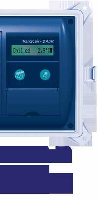
9 1.2 Inputs and Outputs TranScan 2 supports the following inputs and outputs: 4 channels of temperature measurement using precision thermistor sensors 4 status or on/off inputs derived from volt free contacts. Three of these are dedicated (Alarm enable, Door and Defrost) and one is user definable An alarm output to warn of out of range temperature conditions The recorder must be powered from a DC voltage supply within the range 10-36V Wiring diagram TWD1117 shows these connections. (See Appendix or visit Principle of Operation TranScan 2 measures temperatures and status (on/off) conditions and automatically stores these in the form of internal journey files. A new journey file is normally created for each day. TranScan 2 may then provide a record of the day s measurements or any previous journey file retained in memory as either a paper ticket printout or in a form that can be transferred to an industry standard PC. The user can choose to print information in either Delivery Ticket (current temperatures) or Journey Ticket (recorded temperature and status conditions) format. When the TranScan data memory is full new recordings automatically replace the oldest recordings. The number of recordings that can be retained at any one time depends on the memory size, recording interval and number of temperature channels in use (See 6.8). 1.4 Main Components TranScan 2 comprises three main components; the Display, the Operator Keys and the Printer The Display This normally shows all enabled channels to one degree resolution together with symbols which indicate the current state of each 9
 and 4.")
10 enabled on/off input. The display mode may be changed to show each temperature channel individually with 0.1 degree resolution or to respectively scroll through all enabled channels (see 3.6) The Operator Keys The operator keys are colour coded and identified with symbols to indicate their function. For a description of the key functions see 3.0 (basic operation) and 4.0 (advanced operation). Seven Telematics TEC_ _Transcan2_UserReferenceManual_Bookmarked 10 These keys are provided with TranScan 2 type T and type C recorders only. These keys are provided with all styles of TranScan 2 - type T, type C and type R.
11 1.4.3 The Printer The printer is fitted to the left of the TranScan display and uses a standard 44mm wide x 44mm diameter paper roll and Epson ERC 05 ribbon cartridge. When a ticket is requested the paper feeds automatically. Replacement rolls and ribbons are available by contacting the Seven Telematics sales team. Please contact +44(0) or sales@seventelematics.co.uk to order your ribbons and rolls today. 2.0 Getting Started See also 3.1 Help Printout Before operating your TranScan recorder for the first time check that is it set to operate to your requirements by carrying out a few simple checks in the following order: 2.1 Set the Language of Operation TranScan 2 is factory set to English. If a different language is required Press and h together and the Display shows Set User Options Press and the Display shows the language selected Press to step through the alternatives available English Francais Deutsch Nederlands Espaîol Portugues Italiano Alt. English Polski Press to confirm selection and to return to the normal Display. 11


12 2.2 Print a Journey Ticket If this is the first time using your TranScan recorder this ticket will show the operating settings. These settings are explored in detail throughout this manual. Type R press three times until the display shows JOURNEY TICKET. After a short pause a Journey Ticket will be printed. Type T and C Press once and the display shows JOURNEY TICKET.After a short pause a Journey Ticket will be printed. Press until the display shows JOURNEY TICKET. Examples of Journey Ticket printouts are shown below: Seven Telematics TEC_ _Transcan2_UserReferenceManual_Bookmarked Journey Ticket (Values) Journey Ticket (Tenths) Journey Ticket (Graph) 12
13 2.3 Check the Vehicle Identifiers Check that the Title and Vehicle descriptions are set correctly. The Title is a total of 16 characters that is usually set to the vehicle operator s company name and is printed on the first line of each report. This is factory set to Company Name. The Vehicle number is an 8 character descriptor normally used for the registration number or trailer number. It is factory set to AB51 CDE for type C and R recorders and TRL 1234 for type T recorders. To change the Title and Vehicle descriptions, See Check the Time and Date The time and date which are printed at the end of the Journey and Delivery Ticket are factory set to GMT immediately prior to despatch from the factory. Once set the Date should never need adjusting during the lifetime of the recorder. The clock includes automatic adjustment for winter/summer time. This automatically adds one hour to the set time between 2:00am on the last Sunday in March and 2:00am on the last Sunday in October. To check the clock time and date press h. To adjust the time and/or date see 4.5 and NOTE: When the time or date are changed a new recording is started and the message NEW FILE will appear on the display. 2.5 Check the Printout Style TranScan 2 can print Journey Tickets in graphical or numeric values (in whole or tenths formats). Delivery Tickets are always printed numerically. To check the print style: Press once to display the type of report selected. Press again to display the alternative choices. Press to confirm your choice and the display shows OK next to the print style selected (display shows Print Values OK, Print Graphs OK and Print Tenths OK ). Journey Tickets can be printed in any format from memory as often as required. 13
14 2.6 Check that all required inputs are being monitored TranScan 2 supports up to 4 temperature channels and 4 on/off inputs but most applications call for two temperature channels only. Inspect the Journey Ticket printout taken and compare with the examples above (see 2.2) to determine how many temperature channels your recorder is monitoring. Examine the display (see 1.4.1) to determine if door and/or defrost monitoring is enabled by reference to the relevant symbols. Exercise these inputs (eg. by opening and closing the compartment door) to check that the input sensors are working correctly by checking that the symbols on the display change accordingly. 2.7 Check that Recordings are Being Made TranScan 2 is factory set to record continuously 24 hours a day 7 days a week. Data is recorded in separate complete 24 hour periods, or daily files, for ease of access. This is known as Automatic Daily Recording (ADR). Although many different recording regimes are possible, this standard setting is very widely used. Normally no action or adjustment is required to start or stop the recording process. Use the display (see 1.4.1) to check that recording is in progress. Seven Telematics TEC_ _Transcan2_UserReferenceManual_Bookmarked 2.8 Check the Recording Interval TranScan 2 is factory set to record every 10 minutes. To check the recording interval Press and the Display will show the recording interval in minutes. To change the recording interval: Press and the Display shows PAUSING Press to show the recording interval selected Press to step through the alternatives available (1, 2, 5, 10, 15, 20, 30, 60 mins) Press to confirm selection and return to the normal Display. NOTE: When recording interval is changed a new recording is started and the message NEW FILE will appear on the display. 14
. 3.1 Help Printout See also 4.1 More Help.")
15 3.0 Basic Operation Basic operation covers the most commonly used facilities such as using the display, setting the print style, obtaining printouts, checking the time and date and setting/accepting alarms. For additional operational information see 4.0 (Advanced Operation). 3.1 Help Printout See also 4.1 More Help. An in-built Help facility is provided to guide the operator through the principal functions of the recorder. For R Type press twice and for T and C Type press twice and the Display shows TranScan Help The ticket will be printed after a short pause or press and the basic help file will be printed. A typical TranScan 2 Help printout is: 15
16 Use the Help Printout to guide you through the operation of the recorder. NOTE: Since we constantly strive to improve the operation and facilities of TranScan recorders the Help Printout produced by your recorder may vary slightly from that shown above. In case of any discrepancy the Help printout produced by your recorder will always describe the correct operation of your recorder. 3.2 To Print a Delivery Ticket Type R Press once and the display shows DELIVERY TICKET After a short pause a Delivery Ticket will be printed. Type T and C Press once and the display shows DELIVERY TICKET after a short pause a Delivery Ticket will be printed. A Delivery Ticket shows the temperatures as measured at the time it is printed and may be used to provide printed confirmation of these at the time of delivery. Seven Telematics TEC_ _Transcan2_UserReferenceManual_Bookmarked 3.3 To Print a Journey Ticket Type R press three times until the display shows JOURNEY TICKET. After a short pause a Journey Ticket will be printed. Type T and C Press once and the display shows JOURNEY TICKET.After a short pause a Journey Ticket will be printed. NOTE: To change the printout between graph and numerical presentation see To Print a Multi-Day Ticket A single printed ticket covering up to the last 7 days recordings may be printed out. This is particularly useful where single journeys cover several days. 16
17 Type R press repeatedly to cycle through the options available. When the display shows the number of days required the Multi-Day printout will be printed after a short pause. Type T and C press repeatedly to cycle through the options available. When the display shows the number of days required the Multi-Day printout will be printed after a short pause. NOTE: To change the printout between graph and numerical presentation see To Print any File From Memory TranScan 2 stores data as Journey Files each of which normally cover a complete 24 hour period. Other types of recording regime are possible to cover specific requirements (see section 4.0). TranScan data memory is battery backed and data is retained without power for a minimum of 5 years. Individual Journey Files may be printed from memory as often as required. NOTE: See 4.2 for further information about printing data from memory and see 6.8 for a description of memory size and data storage capacity. 3.6 To Set the Display Mode The TranScan 2 display can be set to any of the following options: Summary Display All enabled temperature channels are displayed simultaneously (resolution 1.0 degree) together with symbols representing the enabled on/off inputs. This is the factory default setting. Single Display One selected enabled temperature channel is displayed individually (resolution 0.1 degrees) together with its name. This is useful when undertaking a temperature verification or reference check on an individual temperature channel. 17
18 Scroll Display This shows each enabled channel plus the summary display in turn. To change the display mode. Press m and the display shows scroll display. Press m to show the summary. Press m to step through the individual temperature channels enabled. Press at any time to confirm your choice. NOTE: For more information concerning the display symbols and their meaning see To Check and Adjust the Recording Interval TranScan 2 is factory set to record every 10 minutes. To check the recording interval Press and the Display will show the recording interval in minutes. To change the recording interval: Press and the Display shows PAUSING Press to show the recording interval selected Press to step through the alternatives available (1, 2, 5, 10, 15, 20, 30, 60 mins) Press to confirm selection and return to the normal Display. Seven Telematics TEC_ _Transcan2_UserReferenceManual_Bookmarked NOTE: When recording interval is changed a new recording is started and the message NEW FILE will appear on the display. 3.8 To Check and Set Alarm Operation TranScan 2 is factory set with its out of range temperature alarms disabled unless specifically requested. To check if temperature alarms are enabled. Press and the Display shows PAUSING Press and if alarms are not enabled within the recorder configuration the display shows No Alarms 18

19 If alarms are enabled within the recorder configuration a series of options for each channel to which alarms are enabled will be presented. Press to confirm selection and return to the normal Display. NOTE: As well as selecting a temperature alarm via the key it is usual to disable alarms when the refrigeration system is switched off. This is to minimise the occurrence of false alarms. The disable signal is normally derived from a contact within the fridge control panel and must be connected to on/off input # 1 on the TranScan. For further information on alarm operation see Advanced Operation NOTE: Advanced operation covers the less commonly used facilities such as selecting data from memory and printing it, offloading data to a Data Collection Unit or PC, setting user options, adjusting the time and date and programming out of range temperature alarms. For basic operational information see 3.0 (Basic Operation). 4.1 More Help An in-built Help facility is provided to guide the operator through the principal functions of the recorder. Section 3.1 shows how to obtain the basic Help file printout. For advanced operation TranScan 2 also includes a secondary Help file called More Help. Press Help Press repeatedly until the Display shows More and the More Help file will be printed. A typical TranScan 2 More Help printout is: 19
20 Use the More Help Printout to guide you through advanced operation of the recorder NOTE: Since we constantly strive to improve the operation and facilities of TranScan recorders the More Help Printout produced by your recorder may vary slightly from that shown above. In case of any discrepancy the More Help printout produced by your recorder will always describe the correct operation of the your recorder. 4.2 Printing Data from Memory (Select Printout) It is possible to print a list of all files stored in the TranScan data memory, mark a file to identify those that have been printed (subsequent recordings are then identified as New ), print all files contained in memory or select and print one or more files. Press and together and the display shows Select printout Press to scroll through the following options Print file list Print new files Print all files DD MM hh:mm (then use h to move back through older recordings and m to move forwards through newer ones) Seven Telematics TEC_ _Transcan2_UserReferenceManual_Bookmarked DD MM hh:mm is the date and start time of the most recent recording in memory. For standard TranScan 2 operation this will be the current date with a start time of 00:00 (midnight). When the appropriate selection has been made press your choice and printing will begin. to confirm 20
21 4.2.1 Print File List (Select printout) A typical file list printout is : The file list shows the start time of all files contained within the TranScan data memory at the date that the printout is taken. New files are those that have not been printed or have been recorded with start times which are after the time of the marked file. The marked file is indicated by the letter M to the right of the file start time. Old files are those that have been printed or have a start time including and earlier than the marked file. A - Indicates that out of range temperature alarms have occurred during the recording M - Indicates the marked file R - Indicates that the file is a normal recording generated by the TranScan ADR clock system Print New Files Press and together and the display shows Select printout Press repeatedly until the display shows Print new files Press and all files recorded with start times after the marked file will be printed starting with the most recent recording. 21
22 NOTE: When all new files have been printed the mark (M) is automatically moved to the most recent recording in memory and all recordings subsequently made after the printout has been taken will then be identified as new files. See also Marking a file Print all Files Press and together and the display shows Select printout Press repeatedly until the display shows Print all files Press and all files in memory will be printed starting with the most recent recording. NOTE: When all files have been printed the mark (M) is automatically moved to the most recent recording in memory and all recordings subsequently made after the printout has been taken will then be identified as new files. See also Marking a file Seven Telematics TEC_ _Transcan2_UserReferenceManual_Bookmarked Marking a File Press and together and the display shows Select printout Press repeatedly until the display shows the date and time of the most recent recording in memory. Press h to move back through older recordings and m to move forwards through newer ones and then press or to mark a chosen file. NOTE: The marking of files for printing data from memory is completely independent of that when offloading recordings to a Data Collection Unit or PC (see 4.3.5). 4.3 Offloading Data to a Computer (Select filedump) Data recorded by the TranScan may be offloaded for archiving on an office computer. TranScan supply a Data Collection Unit (DCU) and software for this purpose. Alternatively a PC running TranScan Data Management software may be connected directly to the TranScan. Offloading data is a copying process and does not remove or delete data from the TranScan data memory. 22
23 NOTE: Data is offloaded through the communications socket located on the front fascia of the TranScan (see 1.4.2) using a lead and jack plug to connect to a DCU or PC running software supplied by TranScan For further information concerning data offloading, compatible equipment and software contact the TranScan Sales Desk or your accredited TranScan dealer. Press and together and the display shows Select filedump Press to scroll through the following options Upload file list Upload new files Upload old files Upload all files DD MM hh:mm (then use h to move back through older recordings and m to move forwards through newer ones). DD MM hh:mm is the date and start time of the most recent recording in memory. For standard TranScan 2 operation this will be the current date with a start time of 00:00 (midnight). When the appropriate selection has been made press choice and offloading will begin. to confirm Print File List (Select filedump) A typical file list printout is: The file list shows the start time of all files contained within the 23
24 TranScan data memory at the date that the printout is taken. New files are those that have not been offloaded or have been recorded with start times which are after the time of the marked file. The marked file is indicated by the letter X to the right of the file start time. Old files are those that have been offloaded or have a start time including and earlier than the marked file. A - Indicates that out of range temperature alarms have occurred during the recording X - Indicates the marked file R - Indicates that the file is a normal recording generated by the TranScan ADR clock system Upload New Files Press and together and the display shows Select filedump Press repeatedly until the display shows Upload new files Press and all files recorded with start times after the marked file will be offloaded starting with the most recent recording. Seven Telematics TEC_ _Transcan2_UserReferenceManual_Bookmarked NOTE: When all new files have been offloaded the mark (X) is automatically moved to the most recent recording in memory and all recordings subsequently made after the offload will then be identified as new files. See also Marking a file Upload Old Files Press and together and the display shows Select filedump Press repeatedly until the display shows Upload old files Press and all files recorded with start times earlier than the marked file will be offloaded starting with the marked file. Offloading old files does not alter the marked file Upload All Files Press and together and the display shows Select filedump Press repeatedly until the display shows Upload all files 24
25 Press and all files in memory will be offloaded starting with the most recent recording. NOTE: When all files have been offloaded the mark (X) is automatically moved to the most recent recording in memory and all recordings subsequently made after the offload will then be identified as new files. See also Marking a file Marking a File Press and together and the display shows Select filedump Press repeatedly until the display shows the date and time of the most recent recording in memory. Press h to move back through older recordings and m to move forwards through newer ones and then press or to mark a chosen file. NOTE: The marking of files for offloading data to a Data Collection Unit or PC is completely independent from marking files for printing data from memory (see 4.2.4). 4.4 Setting User Options It is possible to customise the operation of the TranScan through the User Options feature. To review or change the User Options for a recorder Press and h together and the display shows Set User Options Press to select the operator language English Francais Deutsch Nederlands Espaîol Portugues Italiano Alt. English Polski Press to select the print direction as FORWARD or REVERSE Press h to select recorder type as R or T. Select T for type T and type C recorders Press m to select operation in C or F In all cases press to confirm a choice from the options available. The or key return the recorder to the normal operating display. Journey tickets may be printed in a forward or reverse direction as 25
26 determined by the selected print direction. The results look similar but timed data is always printed in the reverse time direction (most recent first) independently of the direction of printing. The default settings for print direction are: Type T / C REVERSE direction Type R FORWARD direction These settings ensure that printed data emerges from the printer with the text readable as it is being printed (ie not upside down). However this will result in the data being presented differently when comparing printouts produced by type R recorders with those produced by type T / C recorders. If the direction of data on printouts is important for ease of comparing recordings printed by type R recorders with those printed by type T / C recorders then it will be necessary to set the print direction the same for both types. 4.5 Adjusting the Time and Date The time and date are factory set to GMT prior to despatch from the factory. The clock includes automatic adjustment for winter/summer time. This automatically adjusts the set time between 02:00 on the last Sunday in March and 02:00 on the last Sunday in October. (When the local time is different from GMT this should be taken into account when setting the clock, see ). Seven Telematics TEC_ _Transcan2_UserReferenceManual_Bookmarked Clock Protect Adjustment of the real time clock can be security protected by the Configuration Parameter Clk Protect. This is factory set to OFF but can be set to ON to prevent unauthorised adjustment of the time. To check if the clock protect is enabled; Press and the display shows PAUSING Press h or m and if the clock protect is enabled the display shows PROTECTED. When the clock protect is enabled the clock can only be adjusted by using the PIN protected Configuration Mode. (See 4.5.3). 26
27 4.5.2 Clock Adjustment (clock protect not enabled) When the clock protect is not enabled; Press and the display shows PAUSING Press h to adjust hours and m to adjust minutes Clock Adjustment (clock protect enabled) To adjust the clock when the clock protect is enabled (see 4.5.1) it is necessary to enter the PIN protected Configuration Mode as follows. PIN code (1,1,1,1) is the factory default value (see 5.0, 5.2 and ). Press and and the display shows Enter PIN code Press,,, and the display shows Start time>00:00 Press and hold until the display shows ENG Display>OFF Press h and the display shows ENG Display> ON Press until the display shows Set clock >hh:mm Adjust the date by moving the cursor with the and keys and then making the adjustment with the and keys. When clock adjustment is complete: Press until the display shows ENG Display> ON Press h and the display shows ENG Display>OFF Press to return to the normal operating display. NOTE: When the time or date are changed a new recording is started and the message NEW FILE will appear on the display. 27
28 4.5.4 Date Adjustment The date is factory set and the clock system includes a calendar up to the year The date can only be changed by entering the PIN protected Configuration Mode as follows. PIN code (1,1,1,1) is the factory default value (see 5.0, 5.2 and ). Press and and the display shows Enter PIN code Press,,, and the display shows Start time>00:00 Press until the display shows ENG Display>OFF Press h and the display shows ENG Display> ON Press until the display shows Date>15 Sep 13 Adjust the date by moving the cursor with the and keys and then making the adjustment with the and keys. When date adjustment is complete: Press until the display shows ENG Display> ON Press h and the display shows ENG Display>OFF Press to return to the normal operating display. Seven Telematics TEC_ _Transcan2_UserReferenceManual_Bookmarked NOTE: When the time or date are changed a new recording is started and the message NEW FILE will appear on the display. 4.6 Temperature Alarms Upto four complete alarm sets may be defined (Alarm Sets 1 to 4) and each temperature channel may be provided with the option for Alarm Set 1, Alarm Set 2, Alarm Set 3, Alarm Set 4, Auto Alarms and No Alarms by setting these to ON in configuration mode. All Temperature Alarms are recorded in the memory of the recorder. The Auto Alarms facility enables usage of all alarm sets simultaneously so that an alarm will occur unless the temperature is within the acceptable ranges defined by any of these alarm sets. 28
29 4.6.1 Alarm Sets Each alarm set has the following parameters that may be defined in configuration mode: Alarm Name A Seven Character Description eg Frozen High alarm the upper acceptable limit eg 15C Low alarm the lower acceptable limit eg 25C Alarm wait the time delay on alarm activation eg 30m Graph high the upper limit of the graph printout eg 10C Graph low the lower limit of the graph printout eg 30C Enabling/Disabling Alarms The TranScan 2 is factory set to record 24hrs/day and if alarm monitoring is required care must be taken to ensure that any alarms are deactivated when the fridge system is switched off for extended periods or when the vehicle is not in use. Otherwise false alarm signals may be generated. To automate the process of alarm suppression it is possible to connect an on/off signal to Status input #1 so that the alarms will only be active when, say, the input is closed. This signal may be derived from the refrigeration unit so that any alarms selected will be automatically enabled when the fridge is operational. Refer to the wiring diagram provided with the TranScan 2 kit for connection details. Additionally this enable action may be extended for a period after the input signal is removed (eg to allow the fridge to be switched off momentarily during delivery) via the parameter Extend Time. To facilitate the alarm control feature: Enter configuration mode. PIN code (1,1,1,1) is the factory default value (see 5.0, 5.2 and ). Press and and the display shows Enter PIN code Press,,, and the display shows Start time>00:00 29
 Press h to set Alrm reverse > ON Set an alarm extend time Press until the display shows Extend time >OFF (or ON) Press h to set Extend time > ON Press until the display")
30 Set the alarm control input to respond to a contact closure signal: Press and hold until the display shows Alarm control >OFF (or ON) Press h to set Alarm control > ON Press until the display shows Alarm reverse >OFF (or ON) Press h to set Alrm reverse > ON Set an alarm extend time Press until the display shows Extend time >OFF (or ON) Press h to set Extend time > ON Press until the display shows Added time >00:00 Set an added time by moving the cursor with the and keys and then making the adjustment with the and keys. Connect the Fridge on/off detector to an appropriate signal in the refrigeration unit and then connect the output from the detector to Status input #1 on the recorder. When recording is in progress and the Alarm Control is activated the recording indicator on the display alternates between a solid rectangle and the letter A. Seven Telematics TEC_ _Transcan2_UserReferenceManual_Bookmarked Alarm Indicator Light and Buzzer The TranScan 2 can be supplied with an alarm indicator light. Please contact sales office for further information. Refer to the wiring diagram provided with the recorder for connection details of this option. All TranScan 2 recorders include an internal buzzer which activates when an alarm condition occurs. To cancel the buzzer press the key which also prints a ticket as a record of the alarm. The external alarm light will only extinguish when the alarm condition is removed (i.e. temperature returns within acceptable range or alarm is set to OFF).
31 4.6.4 Selecting Alarms Upto four Alarm sets are provided and these are called Alarm Sets 1 to 4. Each temperature channel may be provided with the option of each alarm, all alarms simultaneously (Auto Alarm) or no alarms by setting the appropriate parameters in configuration mode (see 5.2.6, and ). Press Press Press and the display shows PAUSING to review the alarm options available to confirm a selection. Kits which include all the relevant components to facilitate alarm monitoring are available from Seven Telematics or authorised TranScan dealers. 5.0 Configuration Parameters TranScan 2 has been designed to allow a number of variations in the way it operates. This is provided by the configuration parameters and how they are set. TranScan recorders are normally supplied as a kit that includes appropriate components for the application concerned and the configuration parameters are set accordingly. Entry to Configuration Mode is password protected to prevent unauthorised adjustment. When the correct sequence of keys is pressed Configuration Mode is entered and each parameter is then presented on the display one at a time. The user can step through each parameter and make modifications as necessary. In order to enter Configuration Mode a PIN code is required. To enter the PIN code each of the operator keys is associated with a number as follows: = 1, =2, =3, =4, =5, h = 6, m = 7. 31
32 5.1 Printing the Parameters Before attempting to adjust any of the configuration parameters it is recommended that a printout of the parameters is taken. Press and together and the display shows Enter PIN code Press,,, (PIN code 1,2,1,2) and after a short pause the parameters and their current settings will be printed. A typical parameter printout is shown below: Printed Parameter Description Section Product description and sign on message Recording Regime Recording Interval Graph length mm per hour On/Off inputs Alarm Control Graph Scaling Enables temp and alarm channel preset descriptions Temperature channels and descriptions Alarm Parameters Seven Telematics TEC_ _Transcan2_UserReferenceManual_Bookmarked Information to be included in reports Allows access to engineering parameters Vehicle Identifier Additional identifiers e.g. used for Company Name A 4 digit number unique to this parameter set
33 5.2 Accessing Configuration Parameters To enter the configuration mode and adjust individual parameters it is necessary to enter a PIN code: Press and together and the display shows Enter PIN code Press,,, (PIN code 1,1,1,1) and the first parameter Start time > 00:00 is displayed. PIN code (1,1,1,1) is the factory default value (see 5.0 and ). The operating keys have the following functions in configuration mode steps to the previous parameter exits configuration mode steps to the next parameter shifts cursor one place left shifts cursor one place right h scrolls backwards through available characters m scrolls forward through available characters Each parameter consists of a prompt followed by a value that can be changed. Values are one of three different types: ON/OFF values Numeric values Alphanumeric values change between ON and OFF by pressing,, h, or m use and to position the cursor and and to select the value required use and to position the cursor and and to select the character required Product Description and Sign on Message The product description and sign on message appear on the parameter printout (see 5.1) but are not accessible in configuration mode. The sign on message also appears whenever the power to the recorder is restored and is of the format; 33
34 1- I NITIALIZING 2- TranScan Tracker 3- Recorder - T TS2-T Product type Firmware (product software) version Data memory size in Kb NOTE: It is possible to reset the recorder without disconnecting the power. This is called a Soft Reset and will initialise the recorder and display the sign on message. The soft reset does not interrupt the recording process. Press and together and the display shows Enter PIN code Press and together 4 times and the display shows INITIALIZING followed by the sign on message. See also Signature Recording Regime Start time > 00:00 Stop time > 00:00 These define the daily start and stop times for the ADR (Automatic Daily Recording) system. If the start time is after the stop time then the recording continues through midnight. Seven Telematics TEC_ _Transcan2_UserReferenceManual_Bookmarked 34 Log by Day > OFF The TranScan recorder may be set to start and stop recording automatically according to the day of the week as specified by the day code parameter. To use this facility the Log by Day parameter must be set to ON. Day Code > CCCCCCC Each of the seven character codes in this parameter control the recording action for a corresponding day of the week starting with Sunday. The permitted characters and their meaning for each daily code are as follows: 0: not recording 1: record for 24 hours S: start recording at Start time
35 T: terminate recording at Stop time C: start and stop recordings as defined by the start and stop times Using these codes a variety of operating regimes may be user defined Recording Interval min/update > 0010 Sets the rate at which recordings are made. The value written to memory is the average temperature during the update time which is calculated from samples taken every few seconds Graph Length per Hour mms/hour > 0020 Specifies the length of paper ticket used for each hour of elapsed time in graphical reports On / Off Inputs Door switch > ON ON tells the TranScan that status input 2 is to be used as the main door switch contact. A closed contact normally represents a closed door. Door reverse >OFF Normal operation of the door switch is that the switch is open when the door is open. An ON reply to this prompt means that a closed switch will be seen as an open door. DeIce switch> ON ON tells the TranScan that status input 3 is to be used as the DeIce (Defrost) switch contact. A closed contact normally represents defrost cycle is in operation. DeIce reverse> ON An OFF reply to this prompt means that an open contact represents defrost cycle in operation. Spare switch> ON ON tells the TranScan that status input 4 is to be used for monitoring a user defined on/off input or second alarm control. Operation is normally an open contact (ie side door operation). 35
36 Spr reverse>off An ON reply to this prompt reverses the sense of the spare switch input to a closed contact. Spr name>side Dr A 7 character description can be entered for the user defined (spare) input. Spare symbol> A symbol can be selected from four characters for the user defined (spare) input. A door symbol (rectangular box) is the default. The options are-,,,#,! Alarm Control To automate the process of temperature alarm monitoring an on/off input may be connected to Status input #1 so that the alarms will only be active when, say, the input is closed. This signal may be derived from the refrigeration unit so that any alarms selected will be automatically enabled when the fridge is operational. Refer to the wiring diagram provided with the TranScan 2 kit for connection details. See also Alarm enable> ON Tells the TranScan that status input #1 is to be used to enable / disable out of range temperature alarms. Seven Telematics TEC_ _Transcan2_UserReferenceManual_Bookmarked Alrm reverse> ON Tells the TranScan that a closed contact enables the out of range alarm(s). An OFF reply to this prompt reverses the action so that an open contact enables the alarm(s). Extend time > ON Allows the action taken by the alarm control signal to be delayed by a period of time set by the parameter Added time. This allows the alarms to remain active when the fridge is switched off for short periods e.g. when making a delivery. Added time>00:30 Specifies the period of time that the alarms remain active when the fridge is switched off. A maximum value of 23 hrs and 59 minutes may 36
37 be set. The factory set value is 30 minutes. NOTE: When alarms are enabled the recording indicator on the display shows a flashing A Graph Scaling Graph high> 0030 Graph low >-0010 These are the upper and lower limits used for graphical printouts when the alarm is enabled. See also Preset Names Preset names> ON Each temperature channel and alarm set may have its own unique 7 character name or description assigned to it. However if this parameter is set to ON then the name for each channel and alarm set must be selected from the following predefined list: Channel names : Front, Rear, Air Ret, Product, Fr ARet, Rr ARet, Centre, Chill, Freeze Alarm names : Chill, Ambient, F&Veg, Fresh, Alarm, Frozen Predefined names are automatically translated when a different operating language is selected Temperature Channels and Descriptions Temperature1> ON Temperature 1 input (T1) will be measured and displayed when set to ON. An OFF reply to this prompt will turn the measurement off and there will be no display for T1 on the display or in reports. T1 name >Air Ret The name of T1 is shown on the display and in reports. A 7 character description can be used. Other channels (T2 to T4) are similarly programmed. NOTE: When the name is changed a new recording is started and the message NEW FILE will appear on the display. 37
38 Alarm Parameters Four independent alarm conditions may be defined as Alarm sets 1 to 4. Each alarm has the following parameters that may be set when the corresponding Alarm parameter is set to ON. A1 name > a seven character description eg Frozen High alarm> the upper acceptable limit eg 15C Low alarm> the lower acceptable limit eg 25C Alarm wait> the time delay on alarm activation eg 30m Graph high> the upper limit of the graph printout eg 10C Graph low > the lower limit of the graph printout eg 30C Alarms are then enabled for each temperature channel and (when activated by On/Off input #1) are selected by the operator or driver through the keypad as described in Information to be Included in Reports It is possible to define which inputs are printed on reports. For each temperature channel it is also possible to define which alarm sets are active. To appear on the printout the relevant input must be set to ON. Only activate those inputs which are being monitored. Seven Telematics TEC_ _Transcan2_UserReferenceManual_Bookmarked 38 Each temperature channel may be enabled for Alarm Set 1, Alarm Set 2, Alarm Set 3, Alarm Set 4, Auto Alarms and No Alarms by setting these options to ON accordingly. Auto Alarm enables all alarm sets simultaneously for that temperature channel so that an alarm will occur unless the temperature is within the acceptable range defined by the alarm sets Engineering Display ENG Display>OFF This parameter is normally set to OFF. An ON value allows the following parameters to be displayed R standard> 9090 This is a standard calibration constant for the TranScan. This constant can t be modified.
39 T1 cal val> 2252 This is the standard calibration value for the thermistor probes supplied for use with TranScan recorders. This value can t be modified. Other channels (T2 to T4) are similarly programmed. PIN number> 1111 (Factory default value) The PIN can consist of any digits in the range 1-7. Setting a PIN of 0000 has the effect of not requiring a PIN code to be entered in order to access the Configuration parameters. WARNING If the PIN is changed, access to parameters will be denied unless the new PIN code is entered correctly. See 5.0, 5.1 and 5.2 Unit I/D> T12345 This is an individual 6 character identifier which is always set to the serial number of the recorder. The identifier is recorded with the data. The unit I/D is printed on each report. This parameter can t be changed. Baud Rate > 9600 This is the speed of communication when the recorder is connected to a PC or other device via the serial port. Date >15 Oct 01 Adjust the date by moving the cursor with the and keys and then making the adjustment with the and keys. Invalid dates cannot be set. Set clock >12:00 Adjust the clock by moving the cursor with the and keys and then making the adjustment with the and keys. Auto Clk Adj> ON Set this parameter to ON to automatically adjust the time by one hour at 02:00 on the last Sunday in March (add 1 hour) and 02:00 on the last Sunday in October (subtract 1 hour). 39
40 Clk Protect >OFF When this parameter is set to OFF it is possible to adjust the clock without the need to enter Configuration Mode by pressing and using the h and m keys (see 4.5.3) Vehicle Identifiers Vehicle>TRL 1234 A 8 character identifier which may be used to identify the vehicle registration or trailer ID number and which is printed on each report. NOTE: When the vehicle ID is changed a new recording is started and the message NEW FILE will appear on the display. Title 1>XXXXXXXX Title 2>XXXXXXXX A further two 8 character identifiers which are used together to specify a user defined 16 character title line which is printed as line 1 of each report Signature This is a four digit number which uniquely characterises the current settings of the configuration parameters. The signature does not depend on any of the descriptive names. Seven Telematics TEC_ _Transcan2_UserReferenceManual_Bookmarked NOTE: The signature may be inspected without the need for taking a parameter printout by viewing it on the display. This is useful when a quick comparison between a number of recorders is required in order to establish if their parameter settings are identical. Press and together and the display shows Enter PIN code Press and h together and the signature will be shown on the display for a few seconds. Recorders with identical firmware (product software) and different signatures have different parameter settings. To check the firmware of the recorder see Product description and sign on message. 40
41 6.0 Specification TranScan temperature recorders are designed to meet the requirements of EN12830 and other national requirements to support the objectives of directives 92/1/EEC (amended by 93/43/EEC) - usually known as the Quick Frozen Food Directive. 6.1 Type of Application Suitable for recording storage temperatures. Suitable for recording transport temperatures. 6.2 Measuring Range Certified range -30 C to +30 C For Germany -35 C to +25 C Available range -50 C to +50 C 6.3 Autonomous Power Lithium Thionyl Chloride ½ AA battery gives 10 year unpowered retention of data and time/date. The battery is not user replaceable but can be returned to manufacturer for replacement. 6.4 Protection IP65 for Trailer models, IP20 for Rigid models. The recorder but not the internal printer in the Rigid model is protected to IP22. In the event of the printer being subject to drips or spillage, it should be allowed to dry out before use. In order to ensure that a printout may be made on demand, a spare printer roll should be carried at all times. 6.5 Supply Voltage DC 10 V to 36 V. The DC supply shall be either from a vehicle battery fused in-line with a Bussmann type TDS501-2 A (or equivalent T2A fuse approved to EN60127) or from an approved mains operated SELV power supply rated for 3A peaks and limited to 100 VA maximum output. The mains operated power supply should be suitable for IEC 41
42 installation category II. In order to protect the recorder against reversed power supply connections there is a diode in series with the input supply. Occasionally this may impair printer operation at the minimum supply voltage. 6.6 Accuracy Class Class 1. Maximum permitted error under all operating conditions of recorder and sensor is 1 C at a resolution of 0.5 C. 6.7 Recording Interval May be set from 1 minute to 60 minutes in steps of 1 minute. For the installation to comply with current legislation, the user must not set the recording interval less than 10 minutes. 6.8 Recording Duration Memory capacity in days at a 15 minute recording interval 1 or 2 channels 3 or 4 channels 988 days 640 days Seven Telematics TEC_ _Transcan2_UserReferenceManual_Bookmarked 6.9 Data Archiving In order to satisfy the requirements of national legislation, data must be retained for at least one year. The files may be printed on the internal printer or may be transferred via a Data Collector Unit to a PC. The maximum interval at which this can take place may be determined from the above table, but it is recommended to perform the operation monthly. Records from the internal printer should be kept in a clean dry place to ensure that they are readable after one year Time Recording Error Relative error less than 0.1%, typical < 0.01%.error less than 15 min in 7 days, typical <1 min in 7 days Climatic Environment 42
43 Recording -30 C to +70 C Printing -10 C to +50 C Transport and storage unpowered -40 C to +85 C TranScan Trailer for indoor or outdoor use TranScan Rigid for installation in vehicle cabin EMC Conforms with requirements of EN EN EN EN EN ISO Radiated immunity 10v/m. Sensor screens should be bared and clamped to the chassis with the fixture provided. Conforms with BS AU 243 (ISO7637-1) grade Power Surge Conforms with BS AU 243 (ISO7637-1) grade Electrical Safety Conforms with EN Safety may be impaired if installation instructions are not adhered to. NOTE: That the area marked by the symbol at the rear of the TranScan Rigid unit may become hot if the printer is run for an extended time at the upper limit of ambient temperature Periodic Verification In accordance with EN Cleaning and Maintenance Visible surfaces may be cleaned with a damp cloth and mild detergent. There are no general maintenance procedures, but replacement of the paper and ribbon is described in section
44 6.17 IEC Symbols Used Direct current Protective conductor terminal. If the user wishes to bond metalwork to a protective conductor as part of their procedures, this terminal should be used. Caution (refer to accompanying documents). 7.0 Declaration of Conformance Declaration of Conformity to European Council Directives Seven Telematics TEC_ _Transcan2_UserReferenceManual_Bookmarked Seven Telematics Ltd Instruments hereby declare that representative samples of the following products: Models Manufactured by TranScan Trailer (2 ADR) TranScan Rigid (2 ADR) Seven Telematics Ltd 4 Faraday Close Durrington Worthing West Sussex BN13 3RB 44
45 have been tested and found to comply with the essential requirements of the following European Council Directives: Electromagnetic Compatibility 89/336/EEC (amended by 93/68/EEC) Quick Frozen Foodstuffs 92/1/EEC (amended by 93/43/EEC) Low Voltage Directive 73/23/EEC Automotive EMC Directive 95/54/EC by application of the following harmonised European Standards: Temperature Recorders EN12830:1999 Generic Emission Standard EN :1992 Generic Immunity Standard EN :1997 Environmental Testing (Vibration and Shock) EN60068:1993 Degrees of Protection provided by Enclosures EN60529:1992 Safety of Electrical Equipment EN :1993/A1:1995 provided that: The product is correctly installed in accordance with the installation instructions supplied. The product has not been modified in any way. The product bears the CE mark. An authorised copy of this declaration is retained by Seven Telematics Ltd. 45


46 8.0 Appendix of Figu Figure 1.0 Product Overview. Seven Telematics TEC_ _Transcan2_UserReferenceManual_Bookmarked 46


47 res 47
48 TEMPER Figure 1.2 Wiring Diagram TWD T1 T2 T3 T4 GB D T1 8 7 T1 Front Rear TEMPERATURE PROBE CONNECTIONS T2 T T2 T3 Air Re Produ Fr ARe Rr AR T4 2 1 T4 Centre Chill Freeze OFF SEE TABLE S1 8 7 C STATUS INPUT CONNECTIONS DOOR DEFROST S2 S S2 S3 DOOR DEFROST 2 S4 SPARE 1 S4 NOTE: VOLT FREE C Seven Telematics TEC_ _Transcan2_UserReferenceManual_Bookmarked B A POWER SUPPLY & ALARM OUTPUT CONNECTIONS 8 ALARM OUTPUT BACKLIGHT 0 VOLTS IMPORTANT NOTES:- 12/24 VOLTS WARNING LAMP FRIDGE ON/OFF DETECTOR 2 AMP FUSES FITTED AD JACENT TO SUPPLY POINT 4 ALARM INDIC ALARM ENA NEGATIVE SUPPLY (-ve) POSITIVE SUPPLY (+ve) POSITIVE SWITCHED S STANDARD FOR RIGID OPTIONAL FOR TRAILER 48
49 3 2 1 ATURE PROBES - PRESET NAMES F D I ESP P NL Devant Vorne Fronte Frente Frente Voor Fond Hinten Retro Atras Tras Achter t Ret Air Rukluft Air Ret Air Ret Ar Ret Azgluch ct Produit Produkt Prodot Prod. Produto Product t RetArDt Rluft V Fr ARet ARet Fr ARet Fr VrAzlct et RetArFd Rluft H Re ARet ARet At ARet Rr AcAzlct Centre Mittler Centro Centro Centro Midden Surgele Gekuhlt Fresco Frio Fresco Gekoeld Congele Gefrore Surgel. Congel. Congel. Bevroer INCLUDED IN THIS KIT T1 T2 T3 T4 D OFF Aus OFF OFF OFF OFF ON/OFF INPUTS S2 C S3 S4 ONTACTS REQUIR ED FOR ALL ON/OFF INPUTS ATOR ALARM B BLE S1 UPPLY (+ve) /IN CAB 3 Title WON Seven Telematics Thermo King TK Transcan DL-PRO R, R, T or T C or with C with universal universal wiring wiring Size Document Number Rev A3 TWD1117 F Tuesday, June 28, 2005 Date: Sheet of A Please visit for a high definition image 49
50 Figure The Display. Seven Telematics TEC_ _Transcan2_UserReferenceManual_Bookmarked 50
51 51

52 Figure The Operator Keys. Seven Telematics TEC_ _Transcan2_UserReferenceManual_Bookmarked 52

53 53


54 Figure 2.2 Printed Journey Ticket Seven Telematics TEC_ _Transcan2_UserReferenceManual_Bookmarked 54 Journey Ticket (Values) Journey Ticket (Tenths)

55 Journey Ticket (Graph) 55

56 Figure 3.1 Help Printout Seven Telematics TEC_ _Transcan2_UserReferenceManual_Bookmarked 56

57 Figure 4.1 More Help 57

58 Figure Print file list (Select printout). Seven Telematics TEC_ _Transcan2_UserReferenceManual_Bookmarked 58
59 Figure Print file list (Select filedump). 59

60 Figure Alarm Indication Light and Buzzer Seven Telematics TEC_ _Transcan2_UserReferenceManual_Bookmarked 60

61 Figure 5.1 Printing the parameters. Printed Parameter Description Section Product description and sign on message Recording Regime Recording Interval Graph length mm per hour On/Off inputs Alarm Control Graph Scaling Enables temp and alarm channel preset descriptions Temperature channels and descriptions Alarm Parameters Information to be included in reports Allows access to engineering parameters Vehicle Identifier Additional identifiers e.g. used for Company Name A 4 digit number unique to this parameter set
62 Figure Product description and sign on me 1- I NITIALIZ 2- TranScan 3- Recorder 4- TS2-T410. Seven Telematics TEC_ _Transcan2_UserReferenceManual_Bookmarked Product type Firmware (product 62
63 ssage. ING Tracker - T software) version Data memory size in Kb 63

64 For further information on the products and services offered by Seven Telematics please visit TEC_ _Transcan2_UserReferenceManual_Bookmarked UDN-1601-F This manual applies to all Firmware versions from TS2T

65
1636")
66 Seven Telematics Ltd. +44 (0)
EUROSCAN RX2-6 / TX2-6
 Cabin and trailer recorder TABLE OF CONTENTS INTRODUCTION... 4 Data security... 4 Menu 1 Print menu... 6 1.1 Select compartment to print... 6 1.2 Time zone offset for printing... 6 1.3 Print event report...
User Manual. Dryer Controller M720
 User Manual Dryer Controller M720 Hardware version 1.00 Software version 1.00 Preliminary version Manual M720 Dryer controller Page 1 of 42 Document history Preliminary version: - Created in April, 2009
ZX1e ZX2e ZX5e. Document No Issue 01 user manual
 ZX1e ZX2e ZX5e Document No. 996-130 Issue 01 user manual MORLEY-IAS ZX2E/ZX5E Fire Alarm Control Panels Table of Contents 1 INTRODUCTION... 4 1.1 NOTICE... 4 1.2 WARNINGS AND CAUTIONS... 4 1.3 NATIONAL
Intelligent Security & Fire Ltd
 Product Data Sheet Mx-4000 Series User Manual MX-4100, MX-4200, MX-4400, Mx-4400/LE & Mx-4800 Fire Alarm Control Panels The operation and functions described in the manual are available from Software Versions
The Kryos LN2 Liquid Level Control & Cryogenic Temperature Control
 The Kryos LN2 Liquid Level Control & Cryogenic Temperature Control Created for Taylor-Wharton Gas Equipment By Pacer Digital Systems, Inc. INTRODUCTION... 4 TEXT FORMAT NOTATION... 4 SYSTEM COMPONENTS...
Watchguard WGAP864 User Manual
 Watchguard WGAP864 User Manual v1.0 Issued September 2016 1 2 Table of Contents Glossary... 5 1. Introduction to your Watchguard WGAP864... 6 2. Before Operating your Alarm System... 6 3. Understanding
i.c³ User Guide For Helmer i.series Ultra-Low Freezers A/A
 i.c³ User Guide For Helmer i.series Ultra-Low Freezers 360175-A/A Document History Revision Date CO Supersession Revision Description A 18 APR 2014* 9275 n/a Initial release. * Date submitted or change
D8024, D9024, D10024 Analog Fire Alarm Control Panels Programming Guide
 System Reset Trou ble Silence Ala rm Silence Manual Ala rm ENTER NO YES Letters Numb ers Keyword Radionics System Reset Trouble Silence Alarm Silence Manual Alarm ENTER NO YES Le ters Numbers Keyw ord
Introduction. OM-THA2
 Introduction. The OM-THA2 is a multi-function product that monitors Temperature, Humidity and Dew Point, provides alarms for out of range conditions, and continuously logs data. It consists of a base unit
Interactive Fire Control Panel IFS7002 four signal loops Instruction Manual
 Interactive Fire Control Panel IFS7002 four signal loops Instruction Manual Revision 6/01.17 Contents 1. Introduction... 6 2. Terminology... 6 3. Function... 8 4. Technical data... 8 4.1. Physical configuration...
THX-DL Data Logger USER & INSTALLATION MANUAL V
 THX-DL Data Logger USER & INSTALLATION MANUAL V1.2012 www.thermomax-refrigeration.com Contents PRESENTATION Summary of Features 2 INSTALLATION Safety Precautions 4 THX Unit 4 Sensors 4 Alarm Relay 4 Power
REPEATER FS5200R INSTRUCTION MANUAL
 REPEATER FS5200R INSTRUCTION MANUAL Instruction Manual Page1 CONTENTS 1. Introduction... 3 2. Function... 3 3. Technical data... 3 4. Contents of delivery... 4 5. General information... 5 6. Duty Mode...
Spa Touch Control Panel with 2000, 2100 controllers. (Spa Owner s Manual insert)
") Spa Touch Control Panel with 2000, 2100 controllers (Spa Owner s Manual insert) P.N. 7876B February 11, 2015 For Spas equipped with BP2000, BP2100 controllers and Spa Touch panel. Spa Touch Control Panel
Spa Touch Control Panel with 2000, 2100 controllers (Spa Owner s Manual insert) P.N. 7876B February 11, 2015 For Spas equipped with BP2000, BP2100 controllers and Spa Touch panel. Spa Touch Control Panel
Dryer Controller M720
 User Manual Dryer Controller M720 Hardware version 2.00 Software version 2.00 Manual M720 Dryer controller Page 1 of 60 Document history Preliminary version: - Created in April, 2009 Hardware Version 2.00,
Operation Guide 3408
 MO1212-EA 2013 CASIO COMPUTER CO., LTD. Operation Guide 3408 About This Manual Depending on the model of your watch, display text appears either as dark figures on a light background or light figures on
THA2 TEMPERATURE/ HUMIDITY/ DEWPOINT ALARM WITH LOGGING CAPABILITY. 99 Washington Street Melrose, MA Phone Toll Free
 99 Washington Street Melrose, MA 02176 Phone 781-665-1400 Toll Free 1-800-517-8431 Visit us at www.testequipmentdepot.com THA2 TEMPERATURE/ HUMIDITY/ DEWPOINT ALARM WITH LOGGING CAPABILITY Introduction.
User Manual. Humidity-Temperature Chart Recorder. Model RH520
 User Manual Humidity-Temperature Chart Recorder Model RH520 Introduction Congratulations on your purchase of the Extech RH520 Temperature + Humidity Chart Recorder. The RH520 measures and displays Temperature,
TS400. Operating Manual. Test Station for Microtector II Series (G450/G460)
") Operating Manual TS400 Test Station for Microtector II Series (G450/G460) GfG GESELLSCHAFT FÜR GERÄTEBAU MBH KLÖNNESTRASSE 99 44143 DORTMUND, Germany TEL. +49 / (0)2 31 / 5 64 00 0 FAX +49 / (0)2 31 /
Operating Manual TS400 Test Station for Microtector II Series (G450/G460) GfG GESELLSCHAFT FÜR GERÄTEBAU MBH KLÖNNESTRASSE 99 44143 DORTMUND, Germany TEL. +49 / (0)2 31 / 5 64 00 0 FAX +49 / (0)2 31 /
Climapro 2. User manual. wireless room thermostat without receiver. To be left with the user.
 Climapro 2 User manual To be left with the user wireless room thermostat without receiver www.glow-worm.co.uk table of contents READ CAREFULLY BEFORE USING 1 Introducing your Climapro 2... 3 1.1 Description...
Spa Touch Control Panel with BP2100, BP6013 spa controllers. (Spa Owner s Manual insert)
") Spa Touch Control Panel with BP2100, BP6013 spa controllers. (Spa Owner s Manual insert) P.N. 7876C (export) February 12, 2015 For Spas equipped with BP2100, BP6013 controllers and Spa Touch panel. Spa
Spa Touch Control Panel with BP2100, BP6013 spa controllers. (Spa Owner s Manual insert) P.N. 7876C (export) February 12, 2015 For Spas equipped with BP2100, BP6013 controllers and Spa Touch panel. Spa
User s Guide. SUB-MA7240O-0001.OG.Solution doc. Created: 6/05/03. Last Updated: 23/09/03. MA7240AO-0001 Version 1.0
 User s Guide SUB-MA7240O-0001.OG.Solution40-111.doc Created: 6/05/03 Last Updated: 23/09/03 MA7240AO-0001 Version 1.0 2 Table Of Contents User List...6 Quick Reference..7 Features...7 Keypad User's Guide...8
ENERGY LIGHT USER S GUIDE ENERGY LIGHT USER S GUIDE
 ENERGY LIGHT USER S GUIDE Release January 2001 CONTENTS 1.0 GENERAL CHARACTERISTICS... 4 1.1 MAIN CHARACTERIS TICS... 4 2.0 USER INTERFACE (CODE C5121230)... 5 2.1 DISPLAY... 5 2.2 MEANING OF THE LEDS...
Interactive Fire Control Panel IFS7002 one signal loop Instruction Manual
 Interactive Fire Control Panel IFS7002 one signal loop Instruction Manual Revision 4/01.17 Contents 1. Introduction... 6 2. Terminology... 6 3. Function... 8 4. Technical data... 8 4.1. Physical configuration...
UNC100 Integra Manual
 UNC100 Integra Manual New Generation Building Security July 30, 2014 V1.2 Copyright Notice Copyright 1995-2014 by All rights reserved Worldwide. Printed in Canada. This publication has been provided pursuant
Operation Guide 5510
 MO1612-EA 2016 ASIO OMPUTER O., LTD. About This Manual Button operations are indicated using the letters shown in the illustration. Depending on the model of your watch, display text appears either as
BURGLAR ALARM PANEL BS-468
 BURGLAR ALARM PANEL BS-468 Contents 1. Description... 3 2. Instructions for the user... 4 2.1Basic operations... 4 Complete system.... 4 Split system.... 4 2.2 Armed system indication... 5 2.3 Advanced
MAKING MODERN LIVING POSSIBLE. TP7001 Range Electronic 7 Day Programmable Room Thermostat. User Guide. Danfoss Heating
 MAKING MODERN LIVING POSSIBLE TP7001 Range Electronic 7 Day Programmable Room Thermostat Danfoss Heating User Guide TP7001 Electronic 7 Day Programmable Room Thermostat For a large print version of these
Safety Temperature Limiter STL 50 Certified to DIN EN (replaces DIN 3440)
") Safety Temperature Limiter STL 50 Certified to DIN EN 14597 (replaces DIN 3440) Features M For use as: STB Protection - temperature limiter ASTB Exhaust gas - protection - temperature limiter STW Protection
Safety Temperature Limiter STL 50 Certified to DIN EN 14597 (replaces DIN 3440) Features M For use as: STB Protection - temperature limiter ASTB Exhaust gas - protection - temperature limiter STW Protection
8 plus and16 plus. User s Guide * # ent. esc GALAXY 16+ V2.XX TUE 30 JUN. IU ZST 962 Issue 2. A u B u
 8 plus and16 plus User s Guide GALAXY 16+ V2.XX 06.22 TUE 30 JUN 1 2 3 4 5 6 7 8 9 0 * # A u B u ent esc IU1-0018 ZST 962 Issue 2 Contents INTRODUCTION... 1 Glossary of Terms... 3 KEYPAD INFORMATION...
The Challenger Version 8 User Guide
 The Challenger Version 8 User Guide CONTENTS Function included in your system Introduction...4 Glossary... 6 The Challenger Console.. Liquid Crystal Display... 9 Keypad...10 Indicator Lights...11 User
Fridge-tag 2 E OPERATION MANUAL ENGLISH PAGE 1-36 MODE D EMPLOI FRANCAIS PAGE with internal sensor
 with internal sensor OPERATION MANUAL ENGLISH PAGE -36 MODE D EMPLOI FRANAIS PAGE 37-7 ontent Page ) Display explanations 3 2) State of delivery / Sleep Mode 4 3) Gathering information prior to device
Operations Manual TS400. Test Station for G450/G460 Gas Detector
 TS400 Test Station for G450/G460 Gas Detector Operations Manual 1194 Oak Valley Dr, Ste 20, Ann Arbor MI 48108 USA (800) 959-0329 (734) 769-0573 www.goodforgas.com GfG Products for Increased Safety Congratulations
Product Manual SZ1009
 Product Manual SZ1009 Conventional Heating & Cooling Thermostats with Heat Pump Mode Communicating Thermostats Description The SZ1009 is a microprocessor-based mable thermostats designed for conventional
USER MANUAL USB Multi-Function Datalogger Model RHT35
 USER MANUAL USB Multi-Function Datalogger Model RHT35 Additional User Manual Translations available at www.extech.com Introduction Thank you for selecting the Extech multi-function, easy-to-use, portable
USB Multi Function Dataloggers. RHT30 Humidity/Temperature Datalogger. TH30 Dual Temperature Datalogger
 USER MANUAL USB Multi Function Dataloggers RHT30 Humidity/Temperature Datalogger TH30 Dual Temperature Datalogger Additional User Manual Translations available at www.extech.com Introduction Thank you
Using the QRAE Plus personal multigas monitor
 Using the QRAE Plus personal multigas monitor Firmware v 1.10 QRAE Plus The Hazardous Environment Detection Company QRAE Plus features Turning on the QRAE Plus Recommended Daily Start-up Procedure User
HMC300. Control unit. Operating Instructions. EMS plus (2014/10) O
 O") HMC300 Control unit EMS plus 6 720 808 471-00.1O Operating Instructions 6 720 813 192 (2014/10) Contents Contents Key to symbols and safety instructions................3 1.1 Key to symbols...........................
HMC300 Control unit EMS plus 6 720 808 471-00.1O Operating Instructions 6 720 813 192 (2014/10) Contents Contents Key to symbols and safety instructions................3 1.1 Key to symbols...........................
SCAN200E USER S MANUAL
 SCAN200E USER S MANUAL Code No. 2071 1052 rev. 1.4 Code No. 2071 1052 Rev. 1.4 Page 2/16 SCAN200E User s Manual Foreword This manual is for SCAN200E Controller running software version 2.03 or later. We
Section 9 System Operation
 Section 9 System Operation Operation of the control panel is simple. Menus guide you step-by-step through operations. This section of the manual is an overview of the operation menus. Please read this
one Operating instructions SenTRI ONE panel-based Fire detection and alarm system
 SenTRI ONE panel-based Fire detection and alarm system one 042bc/14 4188-978 issue 2_04-10_SenTRI ONE system oper Part of Document pack 2535-235 issue 2 1 Contents User responsibility - - - - - - - - -
FLOW CONTROLLER TYPE S/601
 Checked Version Release date QA V4.2.6 F1 F2 EN 26.01.2012 Manual FLOW CONTROL FLOW CONTROLLER TYPE S/601 MODELS F1 AND F2 INTRODUCTION Thank you for using the S/601 flow and batch control series. This
Operating instructions SENTRI4 Control panel based Fire detection and alarm system
 1 2 3 4 5 6 7 8 9 10 11 12 13 14 15 16 17 18 19 20 21 22 23 24 25 26 27 28 29 30 30 32 Zones Healthy 15:45 Fault Power Fault System Fault SenTRI 4 Fire System Designed to EN54 Pt 2 & 4 Operating instructions
Operation Manual Fighter ProVision Software. Version: 0.0 Revision: 1
 Operation Manual Fighter ProVision Software Version: 0.0 Revision: 1 TABLE OF CONTENTS 1. Introduction 5 2. Software Installation 5 3. PC Users 6 3.1 Introduction 6 3.2 Default Code 6 3.3 Edit PC User
ECOLOG TN2, TN3-P, TN4, TN4-L, TP2, TP4-L,TH1, TH2
 TN2, TN3-P, TN4, TN4-L, TP2, TP4-L,TH1, TH2 1. Product Overview 1.1 Display Large LCD display for measured values and status Time Alarm (will stay lit until Upper / Lower limit value (except for TN2) the
Fridge-tag 2 OPERATION MANUAL ENGLISH PAGE 1-36 GEBRAUCHSANWEISUNG DEUTSCH SEITE with internal sensor
 with internal sensor OPERATION MANUAL ENGLISH PAGE -36 GEBRAUHSANWEISUNG DEUTSH SEITE 37-7 ontent Page ) Display explanations 3 2) State of delivery / Sleep Mode 4 3) Gathering information prior to device
ViewMatrix. Software for Online Monitoring & Control of Matrix2000 Conventional Fire Alarm Panels. Version: 2.0 Revision: 0.1
 ViewMatrix Software for Online Monitoring & Control of Matrix2000 Conventional Fire Alarm Panels Version: 2.0 Revision: 0.1 CONTENTS 1. Introduction...3 2. Keyboard...5 2.1 POWER indication - Normal Operation...5
Fridge-tag 2 OPERATION MANUAL ENGLISH PAGE 1-34 GEBRAUCHSANWEISUNG DEUTSCH SEITE with internal sensor
 with internal sensor OPERATION MANUAL ENGLISH PAGE -34 GEBRAUHSANWEISUNG DEUTSH SEITE 35-68 ontent ) Display explanations ) State of delivery / Sleep Mode 3) Gathering information prior to device activation
LogTag TICT - is0 Tag
 TICT - is0 Tag Freeze Indicator with display DOCUMENT REVISION 1.0, 4 March 2014 Copyright 2014, LogTag Recorders Limited Contents Contents... 2 Document revision history... 2 Description... 3 Alerts...
LogTag Recorders TRED30-16R. Temperature Recorder with Display and 30 Day Statistics Memory. Product User Guide
 LogTag Recorders TRED30-16R Temperature Recorder with Display and 30 Day Statistics Memory Product User Guide Document Release Version: 1.4 Published 1. March 2017 Copyright LogTag Recorders, 2004-2017
Section 8 System Operation
 Section 8 System Operation Operation of the control panel is simple. Menus guide you step-by-step through operations. This section of the manual is an overview of the operation menus. Please read this
Dryer Moisture Systems Inc. Dryer Master M 2. Product Manual
 Dryer Moisture Systems Inc. Dryer Master M 2 Revision 1. January, 27 Revision 1.1 March, 27 Revision 1.2 June, 27 Revision 1.22 July, 27 Revision 1.22.1 January, 28 Revision 1.22.2 April, 28 Revision 1.23
XP95/Series 90 Test Set
 PP1072/2003/Issue 5 XP95/Series 90 Test Set XP95/SERIES 90 TEST SET BIT 0 BIT 1 BIT 2 NEW TEST MIN/MAX DOWN * UP # LOOP POWER OFF ON OUTPUT HEALTHY LOOP + - User Manual 1 Apollo XP95/Series 90 Test Set
Tempered Water Logic Control OPERATION l TROUBLE SHOOTING
 Tempered Water Logic Control OPERATION l TROUBLE SHOOTING English For MPE Multiple Chiller Units Control Panel TEMPERED WATER SYSTEMS L-2199 Rev. 20080223 Revision: L-2199 20101104 *** IMPORTANT NOTICE
Using Your. Security System With LED Keypad S5030, S5031, S5032
 Using Your Security System With LED Keypad S5030, S5031, S5032 Contents 1 Overview Your Security System... 1 How Your Security System Works... 2 Your System's Programming... 3 Getting Used to Your System...
JA-63 Profi User manual
 JA-63 Profi User manual Contents: 1 Limited warranty... 2 2 Indicators... 3 3 Controlling the system... 4 3.1 Arming... 5 3.2 Disarming... 6 3.3 Panic Alarm... 6 3.4 To stop ALARM... 6 3.5 Home arming...
Fire Extinguishing Control Panel INSTRUCTION MANUAL. Revision 8/ Instruction Manual Page 1 Revision 8/01.17 of 63
 Fire Extinguishing Control Panel FS5200Е INSTRUCTION MANUAL Revision 8/01.17 Instruction Manual Page 1 1. 2. 3. 4. 4.1. 4.2. 4.2.1. 4.2.2. 4.2.3. 4.2.4. 4.2.5. 4.2.6. 4.2.7. 4.2.8. 4.2.9. 4.2.10. 4.2.11.
Installation & User s Instructions
 Installation & User s Instructions 8 080 shown Part No. 00 day Wired Digital Programmer & Room Sensor Part No. 080 day Wireless Digital Programmer & Room Sensor Part No. 00 hr Wireless Digital Programmer
Omniguard 4: Features
 OMNIGUARD 4 The clear choice for monitoring and documenting Vacuum and Pressure in a containment area. Ideal for Asbestos, Lead and Mold abatement and Clean Room monitoring. Omniguard 4: Features The Omniguard
User manual CLIMATIC 200/400 - Controller. Providing indoor climate comfort
 User manual CLIMATIC 2/4 - Controller Providing indoor climate comfort MUL35E-56 9-26 INDEX CONTENTS PAGE INDEX 1 GENERAL DESCRIPTION 2 THE KEYPAD, Climatic 2 3 THE KEYPAD, Climatic 4 4 THE KEYPAD REMOTE
MicroTech Series 200 Centrifugal Chiller
 Protocol Data Information Packet Version 2.2 Group: Controls Date: March 1999 MicroTech Series 200 Centrifugal Chiller Data Communications Packet for Protocol 2002 McQuay International Revision History
Tinytag Plus LAN Data Logger with Temperature & Relative Humidity Probe (-25 to +85 C/0 to 100% RH) Standalone. Tinytag Connect
 Standalone. Tinytag Connect") connect The TE-4500 is a temperature and relative humidity data logger that plugs directly into a network point and communicates across a LAN. The logger can be managed as a standalone logger, in conjunction
connect The TE-4500 is a temperature and relative humidity data logger that plugs directly into a network point and communicates across a LAN. The logger can be managed as a standalone logger, in conjunction
No part of this publication may be reproduced, stored in an automated data file or made public in any form or by any means, whether electronic,
 No part of this publication may be reproduced, stored in an automated data file or made public in any form or by any means, whether electronic, mechanical, by photocopying, recording or in any other manner
UTRED day Logger with display
 UTRED30-16 30 day Logger with display Technical User Manual Published September 2018 Copyright LogTag Recorders, 2018 Contents Safety Information... 3 Liability... 3 Battery Life... 3 Disclaimer... 3 Typographical
Operating instructions for moisture analyzers - UX 3001 (UX 3011, UX 3031, UX 3081) series
 series") NPA Basic information Intended use ULTRA X moisture analysers are used to quickly measure moisture and dry matter in solid, viscous and fluid substances by means of thermo gravimetric analysis. A sample
NPA Basic information Intended use ULTRA X moisture analysers are used to quickly measure moisture and dry matter in solid, viscous and fluid substances by means of thermo gravimetric analysis. A sample
Operations Manual TS400. Test Station for G450/G460 Gas Detector
 TS400 Test Station for G450/G460 Gas Detector Operations Manual 1194 Oak Valley Dr, Ste 20, Ann Arbor MI 48108 USA (800) 959-0329 (734) 769-0573 www.gfg-inc.com GfG Products for Increased Safety Congratulations
User Guide
 ABS control panel CP 112 212 ON ON ON ON ON ON User Guide www.absgroup.com ii ABS CONTROL PANEL CP 112 212, USER GUIDE Copyright 2008 ABS Group. All rights reserved. This manual, as well as the software
PHASE NON-COIN USER S MANUAL (S.A.F.E.)
") PHASE 7.2.2 NON-COIN USER S MANUAL (S.A.F.E.) American Dryer Corporation 88 Currant Road Fall River, MA 02720-4781 Telephone: (508) 678-9000 / Fax: (508) 678-9447 E-mail: techsupport@amdry.com www.amdry.com
PHASE 7.2.2 NON-COIN USER S MANUAL (S.A.F.E.) American Dryer Corporation 88 Currant Road Fall River, MA 02720-4781 Telephone: (508) 678-9000 / Fax: (508) 678-9447 E-mail: techsupport@amdry.com www.amdry.com
DIMENS. MIN TYPICAL MAX A 71.0 (2.795) 71.0 (2.795) 71.8 (2.826) B 29.0 (1.141) 29.0 (1.141) 29.8 (1.173)
 71.0 (2.795) 71.8 (2.826) B 29.0 (1.141) 29.0 (1.141) 29.8 (1.173)") Evco S.p.A. Code 104K204E05 page 1/5 EVK204 Digital controller for ventilated refrigerating units, with HACCP and Energy Saving functions version 1.05 GB ENGLISH 1 PREPARATIONS 1.1 Important Please read
Evco S.p.A. Code 104K204E05 page 1/5 EVK204 Digital controller for ventilated refrigerating units, with HACCP and Energy Saving functions version 1.05 GB ENGLISH 1 PREPARATIONS 1.1 Important Please read
Challenger10 Administrators Manual
 Challenger10 Administrators Manual P/N MAADMN-TS1016 REV 01 ISS 18FEB13 Copyright Trademarks and patents Manufacturer Agency compliance Contact information 2013 UTC Fire & Security. All rights reserved.
Product Data Sheet. Remote Terminals. Features:
 Remote Terminals Product Data Sheet Features: Based around two core products, the Mx- 4010 Remote Display Terminal (RDT) and the fully functional Mx-4020 Remote Control Terminal (RCT). Both remote terminals
Brivis Touch Controller. Installer Manual
 Brivis Touch Controller Installer Manual Brivis Touch Controller Kit Scope Please read these instructions carefully before installing this product. This manual covers the installation of the wall mounted
HOBO U14 Data Logger User Manual
 HOBO U14 Data Logger User Manual The U family of data loggers offers reliability and convenient monitoring for applications that require higher accuracy, better resolution, more memory, or USB connectivity
TEMPERATURE CONTROLLER (STANDARD MODEL)
") OPERATING MANUAL TEMPERATURE CONTROLLER (STANDARD MODEL) 689-0000 689-0005 Barnant Company 28W092 Commercial Avenue Barrington, Illinois U.S.A. 60010-2392 (847) 381-7050 (847) 381-7053 (Fax) 800-637-3739
OPERATING MANUAL TEMPERATURE CONTROLLER (STANDARD MODEL) 689-0000 689-0005 Barnant Company 28W092 Commercial Avenue Barrington, Illinois U.S.A. 60010-2392 (847) 381-7050 (847) 381-7053 (Fax) 800-637-3739
IE Instructions and warning book CRONO 7. Weekly digital chronothermostat
 IE Instructions and warning book CRONO 7 Weekly digital chronothermostat Dear Client, Our compliments for having chosen a top-quality Immergas product, able to assure well-being and safety for a long period
USER GUIDE. Paperless Humidity/Temperature Chart Recorder. Model RH520A 21.2 C 13:
 USER GUIDE Paperless Humidity/Temperature Chart Recorder Model RH520A 30 10 100 0 13:45 04-23-04 21.2 C 38 Introduction Congratulations on your purchase of the Extech RH520A Temperature + Humidity Chart
Galaxy Flex V3. User Guide. Honeywell Security. This user manual is located at
 Galaxy Flex V3 User Guide Honeywell Security This user manual is located at www.eaglesecuritysolutions.co.uk Contents Introduction... 5 Controlling your alarm system... 6 Users... 6 Panel control... 6
2000 SERIES DIAGNOSTIC ALARM CONTROL SYSTEM
 2000 SERIES DIAGNOSTIC ALARM CONTROL SYSTEM OPERATING INSTRUCTIONS MODELS: 2300 2500 2700 This information is relevant to systems fitted with Issue 4.1 (or later) Master Keypad Software, also to Networked
Operating Manual UV Monitor UVT 18
 Operating Manual UV Monitor UVT 18 Software Version 1.2 stand: 21/11/2016 UV - Monitor UVT 18 Intended use The signal monitor UVT 18 was developed to control small- and medium-sized UV systems and is fully
TECHNICAL MANUAL CVM 20 C 5005 CV/04-99 GB
 Summary 1 CONNECTIONS... 3 1.1 TEMPERATURE PROBES...3 1.2 LOW VOLTAGE DIGITAL INPUTS...3 1.3 LIVE DIGITAL INPUTS...4 1.4 RELAY OUTPUTS...5 2 POWER SUPPLY... 6 3 SERIAL CONNECTIONS... 6 4 SOFTWARE... 7
Fridge-tag 2 OPERATION MANUAL ENGLISH PAGE 1-35 GEBRAUCHSANWEISUNG DEUTSCH SEITE with external sensor
 with external sensor OPERATION MANUAL ENGLISH PAGE -35 GEBRAUHSANWEISUNG DEUTSH SEITE 36-70 ontent Page ) Display explanations 3 2) State of delivery / Sleep Mode 4 3) Gathering information prior to device
MC200. Users Instructions. HEATING DIVISION Hort Bridge Ilminster, Somerset TA19 9PS Tel: Fax:
 MC200 Users Instructions BSI Registered Firm HEATING DIVISION Hort Bridge Ilminster, Somerset TA19 9PS Tel: 01460 53535 Fax: 01460 52341 FM 414 Ind. & Comm. Air Heaters; Air Moving Equipment; Flues & Chimneys;
QA16 Addressable System
 QA16 Addressable System Operating Manual HORING LIH INDUSTRIAL CO., LTD. www.horinglih.com QA16 System Characteristics Each loop can connect with 250 devices. Easy system programming through PC to panel.
Operating manual. Wascator FOM71 CLS
 Operating manual Wascator FOM71 CLS Operating manual in original language 438 9200-91/EN 2010.05.03 Register now And be able to join the Wascator FOM 71 CLS web site where you can find: General information
PRODUCT SPECIFICATION
 LogTag TEMPERATURE RECORDER Temperature Recorder / Data logger with 30 Day summary display LOGDISP PRODUCT SPECIFICATION Doc Ver 1.1 Released : 4 th May 2010 Copyright 2010, LogTag Recorders Limited LOGDISP
THERMO BUTTON HYGRO BUTTON The smallest temperature and humidity loggers in the world!
 THERMO BUTTON HYGRO BUTTON The smallest temperature and humidity loggers in the world! FOR ALL YOUR TEMPERATURE AND HUMIDITY CONTROLS, PRODUCT TRACKING, TRANSPORT, STORAGE CONTROLS, HACCP! Small, rugged,
IT801 Thermostat. User s Manual. The complete guide to the set up and operation of your new smart Wi-Fi thermostat.
 IT801 Thermostat User s Manual The complete guide to the set up and operation of your new smart Wi-Fi thermostat. The smart Wi-Fi thermostat system learns your comfort preferences, then finds opportunities
user manual Document No , Revision 03 November 2015
 user manual Document No. 996-202-600-3, Revision 03 November 2015 Contents 1 Introduction...1 1.1 Notice...1 1.2 Models...1 2 User Control Levels...2 2.1 Level Definition...2 2.2 User Passwords...2 3 Controls
SAT-3 Room Temperature Controller
 SAT-3 Room Temperature Controller USER S OPERATING INSTRUCTIONS Contents Introduction 5 Features Summary 5 Operation 7 On/Off 7 Room Temperature Adjustment 7 Operating Mode Selection 8 Fan Speed Selection
RAE Systems Systems. User Presentation. October Protection Through Detection
 RAE Systems Systems AreaRAE Inert User Presentation October 2009 www.raesystems.com AGENDA Overview & Features Basic Operation Turning the AreaRAE Inert monitor ON Warnings NORMAL & INERT Mode Displays
Intruder alarm panel Terxon MX Operating instructions
 Intruder alarm panel Terxon MX Operating instructions Operating instructions Perfect Security for home and office These operating instructions are an important product accessory. They contain important
Ref. 1067/024 Ref. 1067/032A Ref. 1067/052A
 DS1067-064D Mod. 1067 LBT20065 REMOTE CONTROLLABLE ALARM CONTROL PANELS Ref. 1067/024 Ref. 1067/032A Ref. 1067/052A PROGRAMMING MANUAL TABLE OF CONTENTS INTRODUCTION... 7 1 CONTROL DEVICES... 8 1.1 1067/022
Operating instructions Vigilon panel and Network node Fire detection and alarm system
 Healthy 15:45 Fault Power Fault Vigilon Fire System GENT 2015 Designed to EN54 Pt 2 & 4 System Fault Operating instructions Vigilon panel and Network node Fire detection and alarm system Test Fire Fault/Dis
Modular Standard HP Chiller 1/4 screw compressor with Carel driver
 Program for pco¹ pco 2 and pcoc Modular Standard HP Chiller 1/4 screw compressor with Carel driver Manual version 1.0 25 September 2003 Program code: FLSTDmMSDE Do we want you to save you time and money?
The Information Contained in this Document is Proprietary and should only be used for Service or Training of Authorized Blodgett Servicers who will
 The formation Contained in this Document is Proprietary and should only be used for Service or Training of Authorized Blodgett Servicers who will be working on the Blodgett XR8 Oven. All other uses are
VLT Vision Logger Temperature Recorder User s Guide
 VLT Vision Logger Temperature Recorder User s Guide SEALED UNIT PARTS CO., INC. 2230 Landmark Place, Allenwood, NJ USA 08720 Tel: (732) 223-6644 Fax: (732) 223-1617 www.supco.com info@supco.com Limited
2) This manual covers Fire and General Alarm systems. The differences are described in the appropriate sections.
 This manual covers Fire and General Alarm systems. The differences are described in the appropriate sections.") ISSUES ISSUE DATE RELEASED DETAILS OF CHANGE AUTHOR 4 Rev 2 September 2004 Changes for 4000 series. DB 4 Rev 3 April 2005 Screen shots updated and other minor changes K.Z. 4 Rev 4 September 2006 4 Rev
ISSUES ISSUE DATE RELEASED DETAILS OF CHANGE AUTHOR 4 Rev 2 September 2004 Changes for 4000 series. DB 4 Rev 3 April 2005 Screen shots updated and other minor changes K.Z. 4 Rev 4 September 2006 4 Rev
Contents. Glossary
 Contents Glossary ------------------------------------------------------------------------------------------------------ 6 1. Introduction to the IDS 1632 -------------------------------------------------------------
Professional Wireless Rain Guage with 4" LCD
 XC0430 User Manual (Non-RC D-M 917MHz) Size:A5 Professional Wireless Rain Guage with 4" LCD CONTENTS INTRODUCTION...1 PRODUCT FEATURES...1 OVERVIEW...2 LCD DISPLAY...3 INSTALLATION OF WIRELESS SENSOR...4
1 DOCUMENT REVISION CONTROL ELEMENTS... 9
 CONTENTS Contents 1 DOCUMENT REVISION... 8 2 SOFTWARE VERSION... 8 3 BASIC DESCRIPTION... 8 4 CONTROL ELEMENTS... 9 4.1 BASIC DISPLAYS...10 4.2 CONTROL KEYS...11 4.2.1 Rotary button (Press / Turn)...11
Pipo Communications. Model ST-888. DTMF ANI/ENI Display Decoder
 Pipo Communications Model ST-888 DTMF ANI/ENI Display Decoder 1516 Cassil Place Hollywood, California 90028-7106 Phone: 323-466-5444 Fax: 323-466-1520 www.pipo.cc Manual # 68-9888 May 1, 2002 Rev. 5/02