The Company. Measurement made easy. For more information. Introduction
|
|
|
- Alexandrina Clarke
- 5 years ago
- Views:
Transcription

1 The Company ABB MEASUREMENT & ANALYTICS USER GUIDE IM/NAV6S/SS-EN REV. G Navigator 600 Silica Measurement made easy We are an established world force in the design and manufacture of instrumentation for industrial process control, flow measurement, gas and liquid analysis and environmental applications. As a part of ABB, a world leader in process automation technology, we offer customers application expertise, service and support worldwide. We are committed to teamwork, high quality manufacturing, advanced technology and unrivaled service and support. The quality, accuracy and performance of the Company s products result from over 100 years experience, combined with a continuous program of innovative design and development to incorporate the latest technology. Cost-effective automated monitoring of phosphate for steam raising applications Introduction The Navigator 600 Silica is an advanced colorimetric analyzer used to measure the level of silica in the steam water cycle in power plants. For more information Further publications for the Navigator 600 Silica are available for free download from: This manual applies only to Navigator 600 Silica model numbers AW641/xxxxx9xx. or by scanning this code: Search for or click on Data Sheet Navigator 600 Silica Silica analyzer PROFIBUS Supplement Navigator 600 Silica and phosphate analyzers Addendum RoHS Directive 2011/65/EU (RoHS II) DS/NAV6S-EN IM/NAV6PBS ADD/MEASUREMENT/001-EN


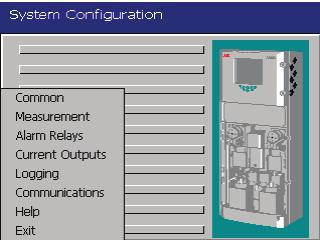


2 Configuration Level Common Configuration Measurement Logging Level* Alarm Relays Current Outputs Logging Communications Not enabled from: Audit Log Alarm Log * This level cannot be accessed from Configuration/Logging
3 Contents Contents 1 Safety Health & Safety Electrical Safety IEC : Symbols IEC : Product Recycling Information Product Disposal Restriction of Hazardous Substances (RoHS) Chemical Reagents Safety Precautions Safety Conventions Safety Recommendations Service and Repairs Potential Safety Hazards Overview Principle of Operation Chemical Principle Liquid Handling Out of Sample Installation Accessories Sampling Requirements Location Reagent Bottle Location Behind Mounting Plate or Wall To Side of Analyzer Below Analyzer Mounting Mounting Dimensions Mounting the Analyzer Mounting the Reagent Shelf (Optional) Electrical Connections Connections Overview Accessing and Making Connections Ethernet Connections Alarm Relay Contact Protection and Interference Suppression Preparing the Analytical Section Connecting Sample Inlet and Drain Line(s) Connecting the Contaminated Drain Tube Configuration Front Panel Controls Navigation and Editing Text Editing Numeric Editing Other Methods of Editing Menus Common Setup Screen Time Security User Messages Measurement Setup Streams Diagnostics Alarm Relays Current Outputs Logging Recording Chart Archive Communications Ethernet and Start-up Commissioning the Analyzer Start-up and Configuration Performing a Baseline Calibration Calibration & Maintenance Zero Calibration Secondary Calibration Cleaning Setup Calibration / Clean Calibration Maintenance Scheduled Maintenance Chemical Solutions Solution Replacement Annual Service Periodic Maintenance Sample Filter Replacement Reagent Tube Filter Replacement DC Fuse Replacement Manual Test Settings Start / Stop Pumps IM/NAV6S/SS EN Rev. G 1
4 Contents 9 Logging SD Cards Reset Archiving File Viewer Archive File Types Data Files Data Filenames Log Files Daylight Saving Filename Examples Chart Functions Historical Review Operator Messages Chart Annotation Screen Interval Scales Trace Select Alarm Acknowledge Diagnostic Information Reagent and Solution Levels System Information Measurement Status Valves and Pumps Status Statistics...61 Appendix D Online Help Appendix E Web Server E.1 Stream Values E.2 Reagent & Solution Levels E.3 Measurement Status E.4 Valve & Pump Status E.5 Statistics E.6 System Information E.7 Logging Status E.8 Operator Messages E.9 Configuration E.10 FTP Access E.11 FTP Access via Internet Explorer E.12 FTP Access via DataManager E.13 File Transfer Program Appendix F Updating the Software Appendix G Analyzing a Grab Sample Appendix H Spare Parts Specification...62 Appendix A Solutions...64 A.1 Reagent Solutions...64 A.2 Secondary Calibration Solutions...64 A.3 Cleaning Solution...65 A.3.1 Regular Cleaning Solution (for Automatic Cleaning Operation)...65 A.3.2 Extra Strength Cleaning Solution (for Troubleshooting and More Intense Wet Section Cleaning)...65 A.3.3 Safety Labels...65 Appendix B Diagnostics and Alarms...66 B.1 Analyzer Diagnostic Information...66 B.2 Audit Log and Alarm Event Log...73 B.2.1 Audit Log Icons...73 B.2.2 Alarm Event Log Icons...73 Appendix C Troubleshooting...74 C.1 Analyzer Malfunction...74 C.2 Calibration Errors and Noisy or Incorrect Readings.74 C.2.1 Air in System...75 C.2.2 Optical System Errors...76 C.2.3 Chemistry and Color Generation Errors...77 C.2.4 Zero and Secondary Calibration Valve Malfunction IM/NAV6S/SS EN Rev. G
5 1 Safety 1 Safety Information in this manual is intended only to assist our customers in the efficient operation of our equipment. Use of this manual for any other purpose is specifically prohibited and its contents are not to be reproduced in full or part without prior approval of the Technical Publications Department. 1.1 Health & Safety Health and Safety To ensure that our products are safe and without risk to health, the following points must be noted: The relevant sections of these instructions must be read carefully before proceeding. Warning labels on containers and packages must be observed. Installation, operation, maintenance and servicing must only be carried out by suitably trained personnel and in accordance with the information given. Normal safety precautions must be taken to avoid the possibility of an accident occurring when operating in conditions of high pressure and / or temperature. Chemicals must be stored away from heat, protected from temperature extremes and powders kept dry. Normal safe handling procedures must be used. When disposing of chemicals ensure that no two chemicals are mixed. Safety advice concerning the use of the equipment described in this manual or any relevant Material Safety Data Sheets (where applicable) may be obtained from the Company, together with servicing and spares information. 1.2 Electrical Safety IEC :2010 This equipment complies with the requirements of IEC :2010 'Safety Requirements for Electrical Equipment for Measurement, Control and Laboratory Use' and complies with US NEC 500, NIST and OSHA. If the equipment is used in a manner NOT specified by the Company, the protection provided by the equipment may be impaired. IM/NAV6S/SS EN Rev. G 3
6 1 Safety 1.3 Symbols IEC :2010 One or more of the following symbols may appear on the equipment labelling: Protective earth (ground) terminal. Functional earth (ground) terminal. Direct current supply only. Alternating current supply only. Both direct and alternating current supply. This symbol indicates the presence of devices sensitive to electrostatic discharge and indicates that care must be taken to prevent damage to them. This symbol identifies a risk of chemical harm and indicates that only individuals qualified and trained to work with chemicals should handle chemicals or perform maintenance on chemical delivery systems associated with the equipment. This symbol indicates the need for protective eye wear. The equipment is protected through double insulation. This symbol, when noted on a product, indicates a potential hazard that could cause serious personal injury and / or death. The user should reference this instruction manual for operation and / or safety information. This symbol, when noted on a product enclosure or barrier, indicates that a risk of electrical shock and / or electrocution exists and indicates that only individuals qualified to work with hazardous voltages should open the enclosure or remove the barrier. This symbol indicates that the marked item can be hot and should not be touched without care. This symbol indicates the need for protective hand wear. Electrical equipment marked with this symbol may not be disposed of in European public disposal systems. In conformity with European local and national regulations, European electrical equipment users must now return old or end-of-life equipment to the manufacturer for disposal at no charge to the user. Products marked with this symbol indicates that the product contains toxic or hazardous substances or elements. The number inside the symbol indicates the environmental protection use period in years. 4 IM/NAV6S/SS EN Rev. G
7 1 Safety 1.4 Product Recycling Information Electrical equipment marked with this symbol may not be disposed of in European public disposal systems after 12 August In conformity with European local and national regulations (EU Directive 2002/96/EC), European electrical equipment users must now return old or end-of-life equipment to the manufacturer for disposal at no charge to the user. Note. For return for recycling, please contact the equipment manufacturer or supplier for instructions on how to return end-of-life equipment for proper disposal. 1.5 Product Disposal Note. The following only applies to European customers. ABB is committed to ensuring that the risk of any environmental damage or pollution caused by any of its products is minimized as far as possible. The European Waste Electrical and Electronic Equipment (WEEE) Directive (2002/96/EC) that came into force on August aims to reduce the waste arising from electrical and electronic equipment; and improve the environmental performance of all those involved in the life cycle of electrical and electronic equipment. In conformity with European local and national regulations (EU Directive 2002/96/EC stated above), electrical equipment marked with the above symbol may not be disposed of in European public disposal systems after 12 August Restriction of Hazardous Substances (RoHS) The European Union RoHS Directive and subsequent regulations introduced in member states and other countries limits the use of six hazardous substances used in the manufacturing of electrical and electronic equipment. Currently, monitoring and control instruments do not fall within the scope of the RoHS Directive, however ABB has taken the decision to adopt the recommendations in the Directive as the target for all future product design and component purchasing. 1.7 Chemical Reagents Warning. To familiarize yourself with handling precautions, dangers and emergency procedures, always review the Material Safety Data Sheets prior to handling containers, reservoirs, and delivery systems that contain chemical reagents and standards. Protective eye wear and protective hand wear. is always recommended when contact with chemicals is possible. 1.8 Safety Precautions Please read the entire manual before unpacking, setting up, or operating this instrument. Pay particular attention to all warning and caution statements. Failure to do so could result in serious injury to the operator or damage to the equipment. To ensure the protection provided by this equipment is not impaired, do not use or install this equipment in any manner other than that specified in this manual. IM/NAV6S/SS EN Rev. G 5
8 1 Safety 1.9 Safety Conventions Warning. In this manual, a warning is used to indicate a condition that, if not met, could cause serious personal injury and / or death. Do not move beyond a warning until all conditions have been met. If a warning sign appears on the instrument itself, refer to Precautionary Labels UL Certification and Electrical Safety CEI/IEC : for an explanation. Caution. A caution is used to indicate a condition that, if not met, could cause minor or moderate personal injury and / or damage to the equipment. Do not move beyond a caution until all conditions have been met. Note. A note is used to indicate important information or instructions that must be considered before operating the equipment Safety Recommendations For safe operation, it is imperative that these service instructions be read before use and that the safety recommendations mentioned herein be scrupulously respected. If danger warnings are not heeded to, serious material or bodily injury could occur. Warning. The installation of the instrument must be performed exclusively by personnel specialized and authorized to work on electrical installations, and in accordance with relevant local regulations Service and Repairs Other than the serviceable items listed in Appendix H, page 86, none of the instrument's components can be serviced by the user. Only ABB personnel or ABB-approved representatives are authorized to attempt repairs to the system and only ABB-approved components must be used. Any attempt at repairing the instrument in contravention of these principles could cause damage to the instrument and injury to the person carrying out the repair. It renders the warranty null and void and could compromise the correct working of the instrument and the electrical integrity or the CE compliance of the instrument. If you have any problems with installation, starting, or using the instrument please contact the company that sold it to you. If this is not possible, or if the results of this approach are not satisfactory, please contact the manufacturer's Customer Service Potential Safety Hazards The following potential safety hazards are associated with operating the analyzer: Electrical (line voltage) Potentially hazardous chemicals 6 IM/NAV6S/SS EN Rev. G
9 2Overview The measurement of silica in a sample involves the addition of various chemical reagents* to the sample, in a specific order and under constant temperature conditions. The result is a chemical complex, in solution, that has a characteristic color. The absorbance of this colored complex is proportional to the concentration of the silica in the original sample, thus making it possible for the measurement to be made optically. During operation, a signal generated from the sensing system is converted by the analyzer into data and this information is presented on the display. Analyzer main components are shown in Fig The hinged lower door provides environmental protection for the liquid handling section to ensure stabilized measurement conditions. 2Overview To maintain optimum measurement accuracy, the analyzer performs a zero and secondary calibration automatically, at predetermined intervals. Data is stored in the analyzer's internal memory and can be archived either to an SD Card or via an internet connection. The SD card can also be used to upgrade the analyzer's software see Appendix F, page 84. *For information about reagent solutions, contact your local ABB representative. Hinged Door to Liquid Handling Section Cable Entries (Both Sides of the Case) Display Electronics Section Keypad Peristaltic Pump Reaction Block Liquid Handling Section *Date Label Constant-head Unit *A second (identical) Date Label is fixed to the underside of the Electronics Section Fig. 2.1 Main Components IM/NAV6S/SS EN Rev. G 7
10 3 Principle of Operation 3 Principle of Operation 3.1 Chemical Principle The chemical method used by the analyzer is based on the reaction of ammonium molybdate with silicate species, under acidic conditions, to form a yellow molybdosilicic acid complex. To improve the sensitivity of the method the yellow complex is reduced to the blue form. The absorbance of the blue complex is measured spectroscopically in the optical system. The sequence of events in the analyzer is as follows: Referring to Fig. 3.2: 1. The sample first flows into a preheater coil (3) that is maintained at a temperature of 75 C (167 F). 2. The sample then passes through the primary debubbler (4) to remove any air bubbles formed during the preheating stage. Referring to Fig. 3.1: 1. The sample now flows into a reaction coil that is maintained at a temperature of 45 C (113 F). 2. The first acid reagent is added to the sample to reduce the ph to a value between 1.4 and Ammonium molybdate is added to the acidified sample. 4. The first reaction coil provides a 2-minute delay where the yellow molybdosilicic acid is developed. 5. The second acid reagent is then added to reduce the ph value further to between 0.8 and 1.0. This is the value required to stop the formation of the yellow complex. The solution enters the second delay coil that provides a further 2 minutes for the reaction to take place. 6. The reduction solution is added to reduce the yellow molybdosilicic acid complex to the more optically-absorbent blue form. The solution enters the third reaction coil that provides a 1 minute delay. 7. The amount of blue color formed is directly proportional to the concentration of silica in the sample. The fully developed solution passes to the measuring cuvette where the intensity of the color is measured. 8. During a zero calibration, the analyzer generates a zero solution by diverting the sample to the point where the second acid is added. The ph at this point is too low for any silica in the sample to react with the molybdate, so a zero solution is produced (refer also to Section 7.1, page 44. During a zero calibration, the system enables any silica present in the first acid and molybdate solutions (Reagents 1 and 2) to form the yellow molybdosilicic acid complex. This is then converted to the blue form when it reacts with the reduction solution. Note. In applications where the sample contains phosphate, the second acid reagent has a different formulation to destroy any molybdophosphoric acid complexes that would form an interfering blue complex in the next stage of the reaction. 8 IM/NAV6S/SS EN Rev. G
11 3 Principle of Operation Reacted sample to optical unit Production of blue molybdosilicic acid complex 0.8 to 1.0 ph providing reducing conditions to stop formation of yellow complex 1.4 to 1.8 ph providing conditions for the production of yellow ß-molybdosilicic acid Temperature controlled at 45 C (167F) 1 Minute Reduction Solution 2 Minutes Second Acid 2 Minutes Molybdate Sample Auto-zero valve First Acid Fig. 3.1 Chemical Schematic IM/NAV6S/SS EN Rev. G 9
12 3 Principle of Operation 3.2 Liquid Handling Referring to Fig. 3.2: The sample enters the analyzer via a constant head unit 1 situated at the bottom of the analyzer. The constant head unit is fitted with an 'Out of Sample' switch that detects a loss of sample. If there is no sample to the analyzer, an automatic shutdown procedure (see Section 3.3, page 12) is initiated. Once the sample returns the analyzer restarts automatically. The sample is drawn up from the constant head unit by the peristaltic pump 2 via a sample filter that protects the liquid handling section from blockages caused by any particulates in the sample. Note. If particulates exceed 60 microns in size, it is essential to fit external filters to the sample lines prior to entering the analyzer. The sample passes through the clean and secondary calibration valves before entering a pre-heater coil 3 that heats the sample to encourage dissolved air in the sample to form bubbles. These bubbles are removed by the primary debubbler 4 and pumped to drain by the de-gassing channel on the peristaltic pump. This is necessary to reduce the effect of bubbles in the sample causing variable reagent mixing, resulting in noisy readings. The sample then passes through the zero valve 5 and into the heated reaction coil 6 where it mixes with the reagents to form a blue complex (described in detail in Section 3.1, page 8). The sample exits the reaction coil and passes into the secondary debubbler assembly 7 which removes any air bubbles that may emanate from the reagents or further degassing of the sample. The degassed sample passes continuously through the measuring cuvette, and then to drain. 10 IM/NAV6S/SS EN Rev. G
13 3 Principle of Operation Peristaltic Pump 2 Rear Pump Capstan Front Pump Capstan 7 To Drain Cuvette Peristaltic Pump Rear Pump Capstan Front Pump Capstan To Drain Calibration Solenoid Valve 3 Cleaning Solution Solenoid Valve Filter Constant-head Unit 1 Sample Cleaning Solution Calibration Solution Reduction 2 nd Acid Molybdate 1 st Acid Fig. 3.2 Flow Schematic IM/NAV6S/SS EN Rev. G 11
14 3 Principle of Operation 3.3 Out of Sample If the analyzer detects that the sample is lost (via the out of sample switch), the analyzer shuts down automatically to prevent air being drawn into the analyzer and to conserve reagents. The automatic shutdown procedure is: 1. The reagent pump stops. 2. Secondary calibration solution is pumped through the system to purge the reaction coil of reagents and developed solution. 3. The sample pump, reaction heater and pre-heater are switched off. 4. The analyzer stays in standby mode until the sample is restored. 5. When the sample returns and the analyzer has been out of sample for less than 24 hours a purge sequence is started. If the analyzer has been out of sample for more than 24 hours a purge and clean sequence is started. As soon as the sample returns, the analyzer restarts, entering a temperature stabilization period followed by a system recovery before measurement resumes. 12 IM/NAV6S/SS EN Rev. G
15 4Installation 4 Installation 4.1 Accessories The following accessories are supplied with the analyzer: 4 x 2.5 l reagent bottle and cap 1 x 500 ml cleaning solution bottle and cap 1 x 500 ml standard solution bottle and cap 1 x DataManager software CD Cable Gland Kit comprising: 10 x two-wire cable glands for relays or Profibus 1 x one-wire cable gland for power 11 x nuts for above glands 11 x O-rings for above glands 1 x large cable gland, washer and nut for Ethernet Annual Spares Kit including: 4 x capstans 2 x capstan covers 1 x set of pump tubes 14 x filter discs Optional accessories that may have been ordered with the analyzer include: 2 x reagent shelves 1 x Profibus card, installed 1 x Profibus manual IM/NAV6S/SS EN Rev. G 13
16 4 Installation 4.2 Sampling Requirements The sampling point must be as near as possible to the analyzer and must provide a thoroughly mixed, representative sample. The sample must conform to the following conditions: Sample must contain less than 10 ppm suspended solids with a particle size no greater than 60 µm. (If particle sizes exceed 60 µm, use a 60 µm filter.) Sample temperature must be within the range 5 to 55 C (41 to 131 F). Sample flow rates must be within the range 20 to 500 ml/min. Sample must be at atmospheric pressure. 4.3 Location For general location requirements refer to Fig Install indoors in a clean, dry, well ventilated and vibration-free location giving easy access and where short sample lines can be used. Avoid rooms containing corrosive gases or vapors for example, chlorination equipment or chlorine gas cylinders. Select a location away from strong electrical and magnetic fields. If this is not possible, particularly in applications where mobile communications equipment is expected to be used, screened cables within flexible, earthed metal conduit must be used. It is also advisable to ensure drains are adjacent and near ground level, so that the analyzer waste outlet can be as short as possible, together with maximum fall. Mount reagent solutions less than 1 m (3.28 ft) from the bottom of the analyzer housing see Fig. 4.2, page 15. Ensure that the power supply and power isolation switch are adjacent to the analyzer. Near to Sample Avoid Vibration Filtered Sample Eye-level Location Above Sea Level < 2000 m (< 6561 ft.) 5 C (41 F) Min. Ambient Temperature Humidity 0 to 95% 45 C (113 F) Max. Fig. 4.1 Location 14 IM/NAV6S/SS EN Rev. G
17 4Installation 4.4 Reagent Bottle Location Behind Mounting Plate or Wall To Side of Analyzer To prevent reagent flow due to gravity during maintenance, Caution. Do not place reagent bottles on the floor. ensure top of reagent bottles are below the level of the pumps. Ensure reagent tubes reach the bottom of all 4 reagent bottles. Dimensions in m (ft.) Dimensions in m (ft.) Ensure top of reagent bottles are below level of pumps Fig. 4.2 Reagent Bottles Mounted Behind the Mounting Plate or Wall Maximum 1 (3.28) Reagent tube length 1.3 (4.26) Maximum 1 (3.28) Reagent tube length 1.3 (4.26) Fig. 4.3 Reagent Bottles Mounted to the Side of the Analyzer Below Analyzer Mount the reagent bottles below the front of the analyzer and install a protective cover (not supplied) over the reagent bottles. Dimensions in m (ft.) Protective Cover (not supplied) Maximum 1 (3.28) Reagent tube length 1.3 (4.26) Fig. 4.4 Reagent Bottles Mounted Directly Below the Analyzer IM/NAV6S/SS EN Rev. G 15
18 4 Installation 4.5 Mounting Mounting Dimensions Dimensions in mm (in.) 314 (12.36) 271 (10.67) 182 (7.16) Maximum 1000 (39.4) 184 (7.25) 289 (11.34) 770 (30.31) 638 (25.12) 122 (4.80) Maximum 1000 (39.4) 280 (11.02) 150 (5.90) 560 (22.05) Reagent bottles mounted on optional brackets (two bottles per bracket) see Sections 4.4.1, and 4.4.3, page 15 for reagent bottle mounting options 300 (11.81) Example two brackets mounted side-by-side with end plates attached to wall Fig. 4.5 Mounting Dimensions 16 IM/NAV6S/SS EN Rev. G
19 4Installation Mounting the Analyzer Dimensions in mm (in.) Mounting the Reagent Shelf (Optional) All Dimensions in mm (in.) 165 (6.59) 114 (4.48) 165 (6.59) 82 (3.23) 525 (20.7) 75 (2.95) 76 (3.00) 75 (2.95) 81 (3.18) Fig. 4.7 Reagent Mounting Shelf (option) Fig. 4.6 Mounting the Analyzer 200 (7.8) Note. Clearance the enclosure doors can open 180. If mounting in a confined area, allow sufficient clearance for cables on the door hinge side (min. 270 mm, 10.6 in.) and 100 mm (3.93 in.) on door opening side. Referring to Fig. 4.6: 1. Mark the wall using the dimensions shown or, with the analyzer supported carefully against the wall, mark through the mounting holes. 2. Drill and plug 3 holes A and B, suitable for M6 or 1 /4 in. fixings. 3. Screw in top fixing A, leaving a gap of 20 mm (0.78 in.) between the fixing head and the wall. 4. Hang the analyzer onto fixing A, ensuring the analyzer is retained firmly against the wall. If used, mount the reagent shelve(s) no more than 1 m (3.3 ft.) from the analyzer s bottom plate see Fig. 4.5, page 16. Each shelf can be attached through the back plate or either of the side plates. If two shelves are attached through their side plates, ensure they are arranged with the back plates facing each other. Referring to Fig. 4.7: 1. Mark the wall using the dimensions shown or, with the shelf supported carefully against the wall, mark through the mounting holes. 2. For each shelf, drill and plug holes suitable for M8 or 5 /16 in. fixings. 3. Hang the shelf onto the screws and tighten the fixings to secure the shelf firmly against the wall. Note. It is not possible to adjust fixing A once the analyzer is placed over it. If necessary, remove the analyzer and adjust the fixing. 5. Secure the analyzer to the wall using 2 fixings B. IM/NAV6S/SS EN Rev. G 17
20 4 Installation 4.6 Electrical Connections Warning. The analyzer is not fitted with a switch therefore an isolation device such as a switch or circuit breaker conforming to local safety standards must be fitted to the final installation. It must be fitted in close proximity to the analyzer within easy reach of the operator and must be marked clearly as the disconnection device for the analyzer. Remove all power from supply, relay and any powered control circuits and high common mode voltages before accessing or making any connections. Use cable appropriate for the load currents: 3-core cable rated 3 A and 75 C (167 F) minimum, and voltage: 100 / 240 V that conform to either IEC or IEC 60245, or to the National Electrical Code (NEC) for the US, or the Canadian Electrical Code for Canada. The terminals accept cables 0.8 to 2.5 mm2 (18 to 14 AWG). Ensure the correct fuses are fitted Fig. 4.8, page 19, for fuse details. Use screened cable for signal inputs and relay connections. Replacement of the internal battery (type Varta CR2025 3V lithium cell) must be carried out by an approved technician only. The analyzer conforms to Installation Category II of IEC All connections to secondary circuits must have insulation to required local safety standards. After installation, there must be no access to live parts, for example, terminals. If the analyzer is used in a manner not specified by the Company, the protection provided by the equipment may be impaired. All equipment connected to the analyzer's terminals must comply with local safety standards (IEC 60950, EN ). Route signal leads and power cables separately, preferably in an earthed (grounded) flexible metal conduit. The ethernet and bus interface connectors must only be connected to SELV circuits. USA and Canada Only The supplied cable glands are provided for the connection of signal input and ethernet communication wiring ONLY. The supplied cable glands and use of cable / flexible cord for connection of the mains power source to the mains input and relay contact output terminals is not permitted in the USA or Canada. For connection to mains (mains input and relay contact outputs), use only suitably rated field wiring insulated copper conductors rated min. 300 V, 14 AWG, 90C. Route wires through suitably rated flexible conduits and fittings. 18 IM/NAV6S/SS EN Rev. G
21 4Installation Connections Overview Note. Field wiring terminal screws must be tightened to a torque of 0.6 to 0.8 Nm (5 to 7 lbf.in). Socket for Optional Digital Communications Hold/Maintenance Relay NO C NC TB2 NO C NC Out of Service Relay O/P 6 Ethernet RJ45 Connector Calibration Failed Relay NO C NC TB3 NO C NC Calibration in Progress Relay O/P 5 O/P 4 TB7 Alarm 2 Relay NO C NC TB4 NO C NC Alarm 1 Relay O/P 3 O/P 2 Current Outputs Alarm 4 Relay NO C NC TB5 NO C NC Alarm 3 Relay O/P 1 TB8 Alarm 6 Relay NO C NC TB6 NO C NC Alarm 5 Relay Optional Digital Communications Use fuse rated: AC Supply DC Supply* Manufacturer* 1 A (max.), Type T, 250 V 12.5 A 125 V DC Type T SCHURTER, Model SPT 5 x 20 Series AC Fuse 1 A Type T or **DC Fuse 12.5 A Type T L N E 100 V to 240 V AC ±10 % (90 V min. to 264 V max.) 50 / 60 Hz + E TB1 18 to 36 V DC **see Fig. 8.4, page 52, for DC fuse replacement details Fig. 4.8 Connections Overview IM/NAV6S/SS EN Rev. G 19
22 4 Installation Accessing and Making Connections Note. Cable entry holes are located on both sides of the enclosure. Application board connection labels for the terminal blocks are identified in Fig. 4.8, page 19. Warning. Remove all power from supply, relay and any powered control circuits and high common mode voltages before accessing or making any connections. A D E J I B C G F H Fig. 4.9 Accessing and Making Electrical Connections Referring to Fig. 4.9: 1. Turn door retaining screws A 1 /4 turn counter-clockwise and open the electronics section door. 2. Using a cross-head screwdriver, remove 4 screws B and remove transparent cover plate C. 3. For each cable entry required, slide retaining clip D off blanking plug E and remove the plug. 4. Fit cable gland F and secure using nut G. 5. Remove gland nut H and feed cable I through it. 6. Feed the cable through cable gland F and into the electronics section enclosure. Note. Cable glands are supplied with single- and twin-holed bushes. Use the single-holed bush for the mains power cable. 7. Remove each connection plug J and, using a small flat-bladed screwdriver, make connections to the plug. Ensure wires are connected to the correct terminals see Fig. 4.8, page Reconnect the terminal block plugs to the appropriate sockets on the application board. 9. Tighten gland nut H for each connection made. 10. If required, fit the Ethernet cable see Section 4.6.3, page Replace transparent cover plate C and secure with 4 screws B. 12. Close the electronics section door and turn door retaining screws A 1 /4 turn clockwise to secure. 20 IM/NAV6S/SS EN Rev. G
23 4Installation Ethernet Connections Warning. Remove all power from supply, relay and any powered control circuits and high common mode voltages before accessing or making any connections Alarm Relay Contact Protection and Interference Suppression NC C NO Relay Contacts R C E H G C D External AC Supply L Load N A AC Applications I NC C NO Relay Contacts F Diode B A External DC Supply + Load B DC Applications Fig Relay Contact Protection Fig Ethernet Connections The Ethernet gland is different from the other connections to accommodate an RJ45 plug: 1. Referring to Fig. 4.9: a. Turn door retaining screws A 1 /4 turn counter-clockwise and open the electronics section door. b. Using a cross-head screwdriver, remove 4 screws B and remove transparent cover plate C. 2. Referring to Fig. 4.10: a. Slide retaining clip A off blanking plug B and remove plug. b. Fit cable gland C and secure using nut D. c. Remove gland nut E and feed cable F through it. d. Fit split-bush G and split-washer H to cable F. e. Feed the cable through cable gland C and into the electronics section enclosure. f. Plug RJ45 connector I into the RJ45 socket on the application board (see Fig. 4.8, page 19 for location details) and tighten gland nut E. If the relays are used to switch loads on or off, the relay contacts can become eroded due to arcing. Arcing also produces RFI that can cause analyzer malfunctions and incorrect readings. To minimize the effects of RFI, arc suppression components are required; these are resistor / capacitor networks for AC applications or diodes for DC applications. These components are connected across the load. Maximum relay ratings are: 250 V, 5 A AC, 1250 VA (non-inductive) 30 V, 5 A DC 150 W For AC applications, the value of the resistor / capacitor network depends on the load current and inductance that is switched. Initially, fit a 100R / µf RC suppressor unit. If the analyzer malfunctions the value of the RC network is too low for suppression and an alternative value must be used. For DC applications fit a diode see Fig For general applications use an alternative IN5406 type (600 V peak inverse voltage at 3 A). Note. The minimum voltage must be >12 V and the minimum current >100 ma for reliable switching. 3. Referring to Fig. 4.9: a. Replace transparent cover plate C and secure with 4 screws B. b. Close the electronics section door and turn door retaining screws A 1 /4 turn clockwise to secure. IM/NAV6S/SS EN Rev. G 21
24 4 Installation 4.7 Preparing the Analytical Section Connecting Sample Inlet and Drain Line(s) Connecting the Contaminated Drain Tube C 9 mm ( 1 /3 in.) PVC Tubing A B B 9 mm ( 1 /3 in.) PVC Tubing A 6 mm ( 1 /4 in.) PVC Tubing Fig Connecting the Contaminated Drain Tube Fig Connecting the Sample Inlet and Drain Line(s) Referring to Fig. 4.12: 1. Connect sample inlet tube to constant-head unit sample inlet connector A. 2. Connect drain tube to constant-head unit outlet connector B. 3. Refer to Section 6, page 41 to startup the analyzer. A contaminated drain tube is supplied fitted to the analyzer. Cut the tube to a suitable length at the free end to ensure it has no kinks and is as short as possible. Keep the tube's cut end in free space to eliminate the risk of air locks. If an alternative contaminated drain tube is used, refer to Fig and route contaminated drain tube A upwards through centre channel B and connect it to contaminated drain collector C. Note. Keep the contaminated drain tube as short as possible and route it as vertically as possible to allow free draining. If samples are to be recycled, use separate drains for contaminated and sample outlets. 22 IM/NAV6S/SS EN Rev. G


25 5 Configuration 5 Configuration 5.1 Front Panel Controls 5.2 Navigation and Editing Depending on the type of field to be edited, the software provides a variety of methods for entering values Text Editing If the field to be edited requires text, a keyboard is displayed: Fig. 5.1 Front Panel Controls a Menu Key Displays or hides the context-sensitive operator menu associated with each view. It also cancels the menu without making a change or returns to the previous menu level. b Group Key Toggles between the operator and log screens. Left Key Scroll left. c Up / Down Keys Highlights menu items and scrolls through previously recorded data. d View Key Toggles between the operator and graph screens. Right Key Scroll right. e Enter Key Selects the highlighted menu item. To enter text, use the,, and keys to highlight the required character and press. There are three set of characters, uppercase, lowercase and symbols. To toggle between each, highlight the bottom, right-hand button and press. To finish, highlight 'OK' and press, or press to exit without making any changes Numeric Editing If the field to be edited requires a numeric value, a number-pad is displayed: To enter a number, use the,, and keys to highlight the required number and press. To finish, highlight 'OK' and press, or press to exit without making any changes. IM/NAV6S/SS EN Rev. G 23

26 5 Configuration Other Methods of Editing There are several other methods of editing, for example: Checkboxes Menus Press to open the menu and use the and keys to select a menu item. Press to open the menu item: To toggle the selection, use the and keys to highlight the required checkbox and press. To finish, highlight 'OK' and press, or press to exit without making any changes. Slider Bars To select a value, use the and keys to move the slider. To finish, press or press to exit without making any changes. Tabs To select a tab, use the and keys. Note. The available. tab indicates that there are more tabs 24 IM/NAV6S/SS EN Rev. G

27 5 Configuration Displayed only if 'Security system' parameter is set to 'Basic' see on-line help system Displayed only if 'Security system' parameter is set to 'Advanced' see on-line help system Invalid Password Entered Configuration Level Protected Edit the current configuration. Changes are not implemented until saved on exit from Configuration Valid Password Entered Configuration Level Unprotected Open a configuration saved previously to internal or external storage (up to 16 configurations can be stored in internal memory) see Note 1 Cancel Toggle between internal / external storage Accept selection See Note 2 Cancel and return to 'Operator' level Open a new configuration with the default settings see Note 1 Fig. 5.2 System Configuration Note. 1. If 'New Configuration' or 'Open Configuration' is selected and the modified configuration file is saved, new data files for all log files are created and any unarchived data is lost. 2. Existing security configuration parameters are retained when a configuration is opened from file or when a new configuration is loaded (the security remains as currently configured). Check 'Load security configuration from file' to overwrite the current configuration with data from the file to be loaded. The option to load or retain the security configuration applies only to Advanced Security mode and is available only to the System Administrator (User 1). If a new or existing configuration file is opened by a user other than the System Administrator, existing security settings are retained. IM/NAV6S/SS EN Rev. G 25
28 5 Configuration 5.3 Common There are nine Common Configuration screens: Setup Fields Language Analyzer Tag Description Lists the available languages. A new language selection does not take effect until the configuration is saved. The analyzer tag text is displayed in the top-left corner of the operator views. Up to 20 characters can be used. The analyzer tag is also displayed on the analyzer on configuration and audit log files Screen Fields Screen saver wait time Screen Capture Brightness Description The time delay for the screen-saver. The screen dims after the time set. Toggles between 'Enabled' and 'Disabled'. Note. An SD card must be fitted for screen capture. If enabled, press to capture the current log or chart screen to the VRD\BMP folder on the SD card. A confirmation dialog box is displayed for each screen capture. Adjusts the brightness of the screen. 26 IM/NAV6S/SS EN Rev. G

29 5 Configuration Time Fields Date and Time Daylight Saving Enable Daylight Saving Start Daylight Saving End Description Warning. Changing the time can result in the permanent loss of data. Once it is changed a warning is displayed stating that recording is disabled until the configuration has been saved. Enables automatic daylight saving time adjustment. Options are: Off. The 'Daylight Saving Start' and 'Daylight Saving End' fields are not available. Auto USA. The start and end of the daylight saving period in the USA is calculated automatically. The clock is incremented automatically by 1 hour at 2:00 am on the second Sunday in March and decremented automatically by 1 hour at 2:00 am on the first Sunday in November. Auto Europe. The start and end of the daylight saving period in Central Europe is calculated automatically. The clock is incremented automatically by 1 hour at 2:00 am on the last Sunday in March and decremented automatically by 1 hour at 2:00 am on the last Sunday in October. Auto Custom. The start and end date and time can be edited. If 'Daylight Saving Enable' is set to USA or Europe, the start date is displayed but cannot be edited. If 'Daylight Saving Enable' is set to 'Custom' the date and time can be edited. If 'Daylight Saving Enable' is set to USA or Europe, the end date is displayed but cannot be edited. If 'Daylight Saving Enable' is set to 'Custom' the date and time can be edited. IM/NAV6S/SS EN Rev. G 27

30 5 Configuration Security 'User 1' is the System Administrator and is the only user that has access to the 'Security type' parameter. User 1 details cannot be changed by any other user. There are two types of security: Basic Enables up to four users to have access to the 'Configuration' menu. Each user has a password that can have up to four digits. A separate password can be set to gain access to the 'Calibration & Maintenance' and 'Logging' menus. All four users use this password. Advanced Enables up to twelve users to have password-protected access to any of the 'Configuration', 'Calibration & Maintenance' or 'Logging' menus. Each user can be assigned a unique 20-digit (alphanumeric) case-sensitive password. A minimum password length can be set. Note. A separate password for access to the 'Calibration & Maintenance' and 'Logging' menus is not required. User 1 can set permissions for each user to access the 'Calibration & Maintenance' and / or 'Logging' menus. Access to the 'Configuration' menu can also be set see Section 5.3.5, page 30. Passwords are set by User 1. If permissions are set, users can subsequently change their own passwords. Password expiry dates can be set. Inactive user accounts can be disabled after a set time. Password failure limits can be set. A minimum password length can be set. 28 IM/NAV6S/SS EN Rev. G
31 5 Configuration Fields Security type Operator level security Operator level password Description A page opens with two fields: Security system toggles between 'Basic' and 'Advanced'. Configuration security toggles between 'Password protected' and 'Internal switch protected'. Set access to the 'Calibration & Maintenance' and 'Logging' menus. If set to 'Off', no password is required. If set to 'On' and 'Security type' is set to 'Basic' an additional 'Operator level password' field is displayed. If set to 'On' and 'Security type' is set to 'Advanced', all users are required to enter their user password to gain access to the 'Calibration & Maintenance' and 'Logging' menus. Displayed only if 'Security system' is set to 'Basic' and 'Operator level security' is set to 'On'. All users are required to enter this password to gain access to the 'Calibration & Maintenance' and 'Logging' menus. The following tabs are displayed only if 'Security System' is set to 'Advanced'. Reconfigure preset Password expiry Inactive user disabling Password failure limit Min password length Passwords are set initially by User 1 (System Administrator) but any user can subsequently change their own password. When set to 'Yes' each user must change their password after it is used for the first time following initial configuration. Select the number of days that the password is valid for. When a password expires, the user is prompted to provide a new password. Select the number of days after which an inactive user's access privileges are de-activated. Enter the number of consecutive incorrect password entries allowed by a user. If the number of incorrect entries exceeds this limit, the user's access privileges are de-activated and can be reinstated only by the System Administrator (User 1). Sets the minimum length required for user's passwords. IM/NAV6S/SS EN Rev. G 29

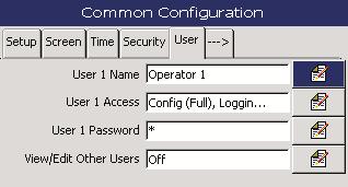
32 5 Configuration User Fields Description If 'Security system' is set to 'Basic' this tab lists the four users, User 1 to User 4. Selecting a user opens a new page with two fields: Name the user s name, up to 20 characters. Password each user can be assigned a unique 4-digit security code for Configuration level access. If 'Security System' is set to 'Advanced' and User 1 (administrator) is logged on, the 'User' tab shows additional fields: User 1 Name User 1 Access User 1 Password View / Edit Other Users User X Name User X Access User 1 identification tag up to 20 characters. A page opens with two checkboxes to select whether User 1 has 'Calibration and Maintenance' and / or 'Logging access'. User 1's password a unique 20-character (alphanumeric) security code. A minimum password length applies. Selects the other user's access levels and passwords. If selected additional fields appear: Where X is the user number (2 to 12) up to 20 characters can be used. Where X is the user number (2 to 12). A dialog box is displayed listing the access available for the user: Calibration & Maintenance Logging Configuration (No access) Configuration (Load) Configuration (Limited) Configuration (Full) User X Password Where X is the user number (2 to 12). The password for User X. If 'Security System' is set to 'Advanced' and a user other than User 1 is logged on, the 'User' tab has three fields. These fields can be edited only if User 1 has set the security field 'Reconfigure preset' to 'Yes' See page 29. Where X is the user number (2 to 12). User X Name User X Access User X Password User X identification tag. Up to 20 characters. Where X is the user number (2 to 12). A dialog box is displayed listing the access available for the user: Calibration & Maintenance Logging User X's password a unique 20-character (alphanumeric) security code. A minimum password length applies. 30 IM/NAV6S/SS EN Rev. G

33 5 Configuration Messages Fields Messages Description Up to 24 messages can be defined to indicate a particular event or action has occurred. These are displayed on the chart when the relevant annotation is enabled. IM/NAV6S/SS EN Rev. G 31
 in 0.1 C (0.")
34 5 Configuration 5.4 Measurement There are three tabs in the 'Measurement' screen: Setup Fields Display Units Reaction / Pre-Heat Temp. Hold Outputs Description The display units for silica concentration. Three options are available: ppb µg/l µg/kg The reaction temperature range is 37 to 50 C (98 to 122 F) in 0.1 C (0.18 F) increments. The analyzer is optimized to run at a reaction temperature of 45 C (113 F). Any changes to the reaction temperature may affect analyzer performance. The pre-heater temperature range is 37 C to 80 C (98 to 176 F) in 0.1 C (0.18 F) increments. The analyzer is optimized for operation at a pre-heater temperature of 75 C (167 F). Any changes to the pre-heater temperature may affect analyzer performance. If set to 'Yes' the current output(s) are held at the reading prior to initiating a calibration. The current output(s) become live again at the end of the recovery period. If set to 'No' the current output(s) are live during the whole calibration sequence. 32 IM/NAV6S/SS EN Rev. G
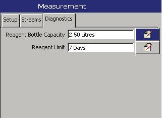
35 5 Configuration Streams Fields Stream 1 Description The page opens with three fields: Stream 1 Tag adds an identification for the stream. Range Low sets the low range value (0 to 5000 ppb). Range High sets the high range value (0 to 5000 ppb). If the difference between the low and high value is too small, the trace displayed appears very noisy. The difference between the low and high value must be at least 50 ppb Diagnostics Fields Reagent Bottle Capacity Reagent Limit Description The Reagent Bottle Capacity can be set between 0.1 and 10.0 liters. This should be changed only if the initial volume of each reagent installed is not 2.5 liters. This value is used to predict the level of reagent remaining in the bottle. The early warning alarm point for the reagent solutions. Can be set between 1 and 30 days. Set to a suitable interval to allow new reagents to be ordered. IM/NAV6S/SS EN Rev. G 33
36 5 Configuration 5.5 Alarm Relays Concentration Concentration Hysteresis Alarm On Trip Point Hysteresis Alarm On Alarm Off Alarm switches off automatically Alarm switches off automatically High Alarm Action Low Alarm Action Fig. 5.3 High / Low Process Alarms Concentration Hysteresis Trip Point Hysteresis Concentration Alarm On Alarm Latched Alarm On Alarm Latched Earliest point that the alarm can be acknowledged Alarm acknowledged by operator Alarm Off Earliest point that the alarm can be acknowledged Alarm Off Alarm acknowledged by operator High Latch Alarm Action Low Latch Alarm Action Fig. 5.4 High / Low Latch Alarms Concentration Hysteresis Trip Point Hysteresis Concentration Alarm On Alarm On Alarm Off Alarm acknowledged by operator Alarm switches off automatically Alarm acknowledged by operator Alarm switches off automatically High Annunciate Alarm Action Low Annunciate Alarm Action Fig. 5.5 High / Low Annunciate Alarms 34 IM/NAV6S/SS EN Rev. G

37 5 Configuration There are six tabs in the Alarm Relays screen, one for each alarm: Fields Alarm Source Description Each of the six alarms can be configured independently to one of the following sources: None no other fields are visible Stream 1 Cleaning in progress If 'Alarm Source' is set to Stream X, additional fields appear: Alarm Type Alarm Tag Trip Hysteresis Fail Safe Log Enable If 'Alarm Source' is set to Stream X, the alarm type can be set to: High / Low process see Fig. 5.3, page 34. High / Low latch see Fig. 5.4, page 34. High / Low annunciate see Fig. 5.5, page 34. Out of sample the alarm state is active if an out-of-sample condition occurs in the selected stream source. The Alarm identification tag up to 20 characters. The value at which the alarm is to activate (0 to 5000 ppb). When an alarm trip value is exceeded, the alarm does not become active until the time hysteresis value has expired. If the signal goes out of the alarm condition before the time hysteresis has expired, the hysteresis value is reset see page 34 for hysteresis actions. The hysteresis value is set in concentration units (0 to 5000 ppb), and the hysteresis time is set in seconds (0 to 5000 s). If set to 'Yes' the alarm relay is normally energized and is de-energized when an alarm condition occurs. If set to 'No' the alarm relay is normally de-energized and is energized when an alarm condition occurs. If set to 'On' all changes in the alarm state in the Alarm Event log are recorded see Section 9.5.2, page 57. IM/NAV6S/SS EN Rev. G 35
38 5 Configuration 5.6 Current Outputs There are six tabs in the Current Outputs screen, one for each output: Fields Output Source Output Range Output Type Out of Sample Ind. Default Output Description The 'Output Source' field has several options: None. No other fields are visible Stream 1 Additional fields appear The high and low limits for the output range. Both values can be set independently (0 to 5000 ppb). If the difference between the zero and span is too small, the output is very noisy. The electrical high and low limits (0 to 22 ma). For example, if the output range is set to 0 to 2000 ppb and the 'Output Type' to 4.00 to ma, at 0 ppb the output is 4.00 ma and at 2000 ppb the output is ma. Out of sample indicator. If set to 'Yes', the output goes to the default output value when an out of sample condition occurs for the selected stream source. The output value used when an out of sample condition occurs and 'Out of Sample Ind.' is set to 'Yes' (0 to 22 ma). 36 IM/NAV6S/SS EN Rev. G

39 5 Configuration 5.7 Logging There are three tabs in the 'Logging' screen: Recording Fields Sample Rate Description The frequency (up to 720 minutes) at which stream data is recorded to the analyzer's internal memory and the SD card (if fitted) Chart Fields Chart view enable Chart annotation Chart divisions Trace pointers Screen interval Description The orientation and direction of the chart display. Options are: Horizontal --> Horizontal <-- Vertical Enables chart annotations to be visible. Options are: None Alarms Alarms & Operator Messages The major and minor chart divisions. Toggles the trace pointers on / off. The amount of data shown on the screen. Trace width The width of each trace in pixels (1 to 3). IM/NAV6S/SS EN Rev. G 37
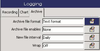
40 5 Configuration Archive Used to configure the data that is to be recorded on the SD card see Section 9, page 53. When external archive media contains approximately 300 files, its read / write performance becomes too slow, archiving is stopped automatically and the icon is displayed alternating with the icon. In this condition, data continues to be recorded on the internal memory. Replace the SD card with an empty card to prevent loss of unarchived data. Fields Archive file format Archive file enables New file interval Wrap Description The file format that archive files saved as. Toggles between 'Text Format' and 'Binary Format'. At least one of these options must be selected for data to be archived automatically to an SD Card. A dialog box is displayed showing the log files that are to be recorded: Text format file containing the stream data. Binary format file containing stream data. Alarm event log file enable (*.e) Audit log file enable (*.a) Available only if 'Wrap' is set to 'Off' and text format is selected. The interval that text format stream data files are created. Options are: Off Hourly Daily Monthly If set to 'On', the oldest archived data on the SD card is deleted automatically when the SD card approaches its maximum capacity. If set to 'Off', archiving stops when the SD card is full. The analyzer continues to store data internally see Section 9, page 53. When an empty SD card is inserted, archiving continues from the point that the last archive was made. 38 IM/NAV6S/SS EN Rev. G

41 5 Configuration 5.8 Communications There are three tabs in the I/O modules screen: Ethernet Configures the way that the analyzer can be accessed via an Ethernet network see Appendix E, page 80. Note. Changes to the 'IP-address', 'Subnet mask' and 'Default Gateway' parameters are implemented only after the analyzer has been restarted. Change the addressing parameters, exit and save the configuration, then power down and restart the analyzer. Fields IP-address Subnet mask Default Gateway FTP user 1 to FTP user 4 Description The IP-address to be assigned to the analyzer. The IP address is used by the TCP/IP protocol to distinguish between different devices. The address is a 32 bit value expressed with four values (0 to 255), each separated by a period (.). The subnet mask is used to indicate which part of the IP address is for the network ID and which is for the host ID. Set each section that is part of the network ID to 255. For example, indicates first 24 bits are for the network ID. The IP address for the 'Default gateway' (for example, router, switch) required to communicate with other networks. The default setting is ' ' Enables up to four users to access the analyzer via the internet. A dialog box is displayed with four options: User name the name of user granted FTP access (up to 12 characters). Password the password required for FTP login (up to 12 characters). Access Level toggles between 'Full' or 'Read-only' access. Remote Operation toggles between 'None', 'Operator' or 'Configuration'. Note. If a user is given full access via FTP, that user is able to select from the saved configuration files in the analyzer. IM/NAV6S/SS EN Rev. G 39
42 5 Configuration and 2 The analyzer can be configured to send s to a maximum of 6 recipients in response to certain events. The addressees can all subscribe to the same SMTP server or the analyzer can be configured to send s via 2 different SMTP servers to a maximum of 3 addressees per server. Up to 10 independently configurable triggers may be enabled to generate an when the selected source becomes active. When a trigger source becomes active, an internal 1 minute delay timer is started. At the end of that minute, an is generated that includes, not only the event that initiated the delay timer, but every other event that occurred during the delay period together with any enabled reports. The data returned in the therefore reflects the real-time alarm state at the time the was generated, not the state when the first trigger source became active. Each sent includes a link to the analyzer's embedded web server, enabling the analyzer's data and status to be viewed remotely using an internet browser on a PC. Fields SMTP Server IP Address Description The IP address of the SMTP server through which s are to be routed. Recipient 1 to Recipient 3 The address of recipient 1 to 3. Inverted Triggers The option to invert triggers 6 to 10. The trigger for an message to be sent. A dialog box is displayed with three options: None no triggers are set. Archive state a dialog box is displayed with six options: Archive media not present Too many files on the archive media Archive media 100% full Archive media 80% full Archive media present Archive on-line Trigger 1 to 10 Event group a dialog box is displayed with nine options: Solutions (reagent, cleaning solution, secondary solution is low or out) Samples (out of one or more samples) Optics (faulty optics) Temperatures (control block / electronics out of limits) Power (excessive current) Calibration (factor / offset error or missed calibration) Hardware (temperature sensor, analog-to-digital converter 1 to 3 failures) Service (service due / media card full) Alarm Relays (alarm relay active) 40 IM/NAV6S/SS EN Rev. G
43 6Start-up 6Start-up 6.1 Commissioning the Analyzer Warning. Protective eye wear and protective hand wear must be worn when contact with chemicals is possible. Take appropriate Health & Safety precautions. Refer to Appendix A for details of reagents, calibration solutions and cleaning solutions. Before operating the analyzer: 1. Ensure the analyzer has been installed correctly see Section 4, page Ensure all reagent, calibration and cleaning solution bottles are filled with the appropriate solutions. 3. Ensure the reagent bottles are mounted safely and securely in the trays* (if supplied) and the bottle tops are fitted securely. *These accessories are not included with all models Start-up and Configuration The following steps describe briefly how to start up and configure the analyzer prior to operation: 1. Clip the pump plattens into place. 2. Ensure a sample stream is connected and flowing. 3. Ensure the drain tube from the analyzer is: a. connected and directed to a drain b. as short as possible and routed as vertically as possible. 4. Switch on power to the analyzer. 5. After the initial power up procedure a message is displayed asking if the 'Power Up Sequence' should be aborted. Select 'Stop' to abort the automatic start up. 6. Check that the failure icon ( ) is not displayed in the diagnostic window. If it is displayed, resolve the cause of the failure before proceeding. 7. Purge the zero calibration line and the secondary and clean solution lines as follows: a. Press the key, select 'Calibration & Maintenance' and select the 'Manual Test Settings' button. b. Select 'Test Pumps' and increase the sample pump speed to 5 rpm using the key pad. c. Exit the 'Test Pumps' page and enter the 'Test Valves' page. d. Select 'Cleaning ON' to energize the clean valve. Leave on for at least 1 minute to flush the clean solution line. e. De-energize the clean valve and energize the secondary calibration valve in the 'Test Valves' page. Leave on for a least 1 minute to flush the secondary solution line. f. De-energize the secondary calibration valve and energize the zero cal valve. Leave on for at least 30 seconds. g. Once all lines have been flushed, select 'Normal Mode' to exit 'Manual Test Settings'. The analyzer returns to the correct pump speed and de-energizes the valves. h. A recovery period is initiated (this can be dismissed to access the menu). 8. Press the key, select 'Calibration & Maintenance' and select 'Solution Replacement'. Select 'Replace Cleaning Solution' and then 'Replace Secondary Cal Solution' this updates the dates they were installed. 9. Select 'Replace All Reagent Solutions' this initiates a purge sequence followed by a recovery sequence that enables the analyzer to stabilize. 10. Initiate a Manual Clean procedure. At this stage a baseline calibration must be performed. Note. The analyzer reading takes some time to settle after the initial Commissioning procedure this is due mainly to the gradual wetting of the internal plastic flow path. Therefore, if an accurate calibration is required it is advisable to wait several hours before initiating a calibration. IM/NAV6S/SS EN Rev. G 41
44 6 Start-up 6.2 Performing a Baseline Calibration Note. Before starting the initial Baseline calibration, it is important to check the reagent lines are fully purged and there is no air flowing through the reaction block. Check there are no air bubbles in the cuvette by checking the stability of the 'Measure Detector mv' signal in the 'Measurement Status' / 'Diagnostic Information' page. If the signal is moving by more than 20 mv over a 30 second period, air may still be present in the cuvette. Initiate a manual clean sequence. To perform a Baseline calibration: 1. Press the key and select 'Calibration & Maintenance' in the menu. 2. Select the 'Calibration' button and press the key. 3. Change the 'Secondary Calibration' value to match the concentration of the secondary calibration solution being used. 4. Start a 'Baseline Calibration'. The 'Baseline Calibration' window is displayed: 42 IM/NAV6S/SS EN Rev. G


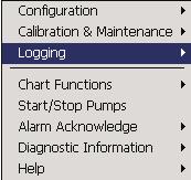
45 7 Calibration & Maintenance 7 Calibration & Maintenance Invalid Password Password Required (if set) Valid Password No Password Required Setup Calibration / Clean see Section 7.4, page 46 Calibration see Section 7.5, page 47 Solutions Replacement see Section 8.1.2, page 49 Annual Service see Section 8.1.3, page 49 Manual Test Settings see Section 8.4, page 52 Fig. 7.1 Calibration & Maintenance Overview A full two-point calibration of the analyzer is performed by running an internally-generated zero calibration and replacing the sample automatically with a secondary calibration solution of a known concentration. Fig. 7.2 Calibration Progress IM/NAV6S/SS EN Rev. G 43
46 7 Calibration & Maintenance 7.1 Zero Calibration During the zero calibration the sample is diverted from its normal flowpath by the Auto Zero valve into the second mixing stage. The ph value at this point is too low to allow the silica-molybdate reaction to take place, consequently a solution equivalent to a zero silica concentration is produced. During the zero calibration the system continues to allow the first acid and molybdate solutions (reagents 1 and 2) to flow, allowing the silica content of these reagents to react and therefore be compensated for in the final measured silica value. Reacted sample to optical unit Production of blue molybdosilicic acid complex 0.8 to 1.0 ph providing reducing conditions to stop formation of yellow complex Temperature controlled at 45 C (167F) 1 Minute Reduction Solution 1.4 to 1.8 ph providing conditions for the production of yellow ß-molybdosilicic acid Sample Auto-zero valve 2 Minutes Second Acid 2 Minutes Molybdate First Acid Small quantity of SiO2 in reagents Fig. 7.3 Chemical Schematic During a Zero Display and Reading ppb SiO2 Baseline Theoretical Response Calibration Factor 1.0 Zero Offset 2 ppb Absorbance Each time the reagents are replenished, a BASELINE CALIBRATION is initiated. During the Zero calibration section, the background offset is compensated for and the Zero Offset parameter is set to 0.0ppb. In a Baseline Calibration the Zero section is always followed by a Secondary Calibration. During continuous running the analyzer exhibits a certain amount of drift (that usually affects the zero calibration) due to: changes in the reagent solutions 'dirtying' of the cuvette windows. If this is not compensated for, by carrying out regular calibrations, significant inaccuracies can be introduced. The degree of zero drift is indicated by the Zero Offset see Fig Fig. 7.4 Zero Calibration 44 IM/NAV6S/SS EN Rev. G
47 7 Calibration & Maintenance 7.2 Secondary Calibration 100 % Display and Reading ppb SiO2 0 % Baseline Theoretical Response Calibration Factor 1.0 Zero Offset 2 ppb Fig. 7.5 Secondary Calibration Absorbance Analyzer Response Calibration Factor 0.9 During the Secondary calibration a known value silica (secondary) standard is passed through the normal sample flowpath, allowing a full chemical reaction to take place. The silica chemistry is so reproducible that this response can be compared to a theoretical response built into the analyzer. The theoretical response has an ideal calibration factor of 1.0. If the response is not perfect, compensation is applied to make the readings correct and the resulting Calibrating factor provides an indication of how much compensation is required see Fig If this is within acceptable limits, the calibration passes and the necessary compensation is applied. If the results are outside acceptable limits the analyzer shows a calibration fail. Calibration options comprise: Baseline (2-point, resets zero) runs both a zero and a secondary calibration. Perform this routine only after the reagents have been replaced or after an annual service. This routine can only be initiated manually. Zero (1-point) required to compensate for any zero drift. Performed weekly or as required to ensure accurate silica measurement. Secondary (1-point) to verify sensitivity (as required) or if the secondary calibration solution has been replaced. Zero & Secondary (2-point) can be performed instead of a weekly zero calibration to compensate for drift and verify sensitivity. The zero, secondary and zero & secondary sequences can be initiated manually or at programmed intervals. Table 7.1 shows the timings for the full calibration sequence. Activity Zero (if required) Stability Secondary Cal (if required) Stability Recovery (introduce sample) Normal Operation Valve Energized Zero Zero Secondary Secondary None None Timing (minutes) Default 35 Up to Up to N/A Calibration Relay Energized Energized Energized Energized Energized De-energized Table 7.1 Calibration Sequence 7.3 Cleaning The analyzer can be programmed to introduce an alkaline cleaning solution through the normal solution flowpath automatically. The alkaline solution has 2 main functions: to remove the build up of precipitation or deposits in the system due to the acidic chemistry conditions inside the reaction block and optical unit. If cleaning is carried out frequently, build up, and its effects on the zero offset, are minimized. to keep all the surfaces very clean and wetted, reducing the effects of bubble formation due to sample and reagent degassing. Cleaning can be initiated either manually or automatically at pre-programmed intervals with an adjustable duration. The ideal frequency and duration of cleaning is determined by monitoring the zero offset parameter at the end of each calibration sequence. If the zero offset is not increasing by more than 1 ppb from one zero calibration to the next, cleaning can be less frequent. The recommended initial starting point is to clean frequently for a short period, for example, weekly for 30 minutes. IM/NAV6S/SS EN Rev. G 45
48 7 Calibration & Maintenance 7.4 Setup Calibration / Clean Enables scheduled calibration and cleaning. Fields Automatic Schedule Secondary Calibration Value Automatic Scheduled Clean Duration Manual Clean Duration Reset Cal. Factor & Offset Description The automatic calibration schedule for the analyzer. A dialog box is displayed with the following options: Zero Frequency the frequency zero calibrations are performed (off to 7 days). Next Zero if 'Zero Frequency' has been enabled, this displays / sets the scheduled date for the zero calibration. Once a scheduled calibration has been performed the date is incremented by the number of days set in 'Zero Frequency'. Important. A warning is displayed if the Next Zero is scheduled 6 hours (or less) after an automatic clean. It is recommended that an automatic clean and zero are separated by 6 hours to ensure the best zero accuracy; this also applies to manually triggered functions. Secondary Frequency the frequency secondary calibrations are performed (off to 4 weeks). Next Secondary if 'Secondary Frequency' has been enabled, this displays / sets the scheduled date for the secondary calibration. Once a scheduled calibration has been performed the date is incremented by the number of days set in 'Secondary Frequency'. Important. A warning is displayed if the 'Next Secondary' is scheduled 6 hours (or less) after an automatic clean. It is recommended that they are separated by 6 hours to ensure the best calibration accuracy; this also applies to manually-triggered functions. Clean Frequency the frequency the analyzer is cleaned (off to 4 weeks). Next Clean if 'Clean Frequency' has been enabled, this displays / sets the scheduled date for analyzer cleaning. Once a scheduled clean has been performed the date is incremented by the number of weeks set in 'Clean Frequency'. Manual Clean to ensure zero accuracy, perform a zero at least 6 hours after the clean sequence has completed. The value of the secondary calibration solution used (10 to 5000 ppb) see Appendix A.2, page 64. Important. This is the same value that is used in the 'Calibration' options see Section 6.2. Changing the value here also changes the value in the 'Calibration' options. The duration used in scheduled automatic cleans (20, 30, 60 minutes, 2, 4, 6, 8, 12 hrs). See Note. The duration used when a manual clean is initiated (20, 30, 60 minutes, 2, 4, 6, 8, 12 hrs). See Note. Immediately resets the calibration factor and the calibration offset to the default factory setting. This option can be used when a calibration has not been performed correctly. A non-adjustable clean duration is used automatically when the analyzer is returned to service following out-of-service conditions such as excessive zero offset, power loss for more than 24 hours and loss of sample for more than 24 hours. Note. All Cleans are followed by an 18 minute recovery period. 46 IM/NAV6S/SS EN Rev. G
49 7 Calibration & Maintenance 7.5 Calibration Enables manual calibrations to be performed. Fields Secondary Calibration Value Description The value of the secondary calibration solution used (10 to 5000 ppb) see Appendix A.2, page 64. Note. This is the same value used in the 'Setup Calibration / Clean' options. Changing the value here also changes the value in the 'Setup Calibration / Clean' options. If the analyzer does not have any active alarms or warnings that can affect a calibration, the following options are available: Baseline (2 point, resets zero offset) Zero (1 point) Secondary (1 point) Zero & Secondary (2 point) Both a zero and a secondary calibration are performed. A new calibration factor is calculated and the Zero Offset is reset to 0.0 ppb. A recovery period follows. A baseline calibration must be performed when the reagents have been replaced or an annual service has been performed. A progress bar is displayed indicating the maximum time required for the operation. A zero calibration is performed and a new zero offset calculated. The recovery period follows. A progress bar is displayed indicating the time required for the operation. A secondary calibration only is performed and a new calibration factor calculated. A recovery period follows. A progress bar is displayed indicating the time required for the operation. Both a zero and secondary calibration are performed. A new zero offset and calibration factor are calculated. A recovery period follows. A progress bar is displayed indicating the time required for the operation. IM/NAV6S/SS EN Rev. G 47
50 8 Maintenance Warning. Ensure personal protective equipment (PPE) such as gloves and eye protection are worn during any maintenance and that any spillages are cleaned-up using clean water. To familiarize yourself with handling precautions, dangers and emergency procedures, always review the Material Safety Data Sheets prior to handling containers, reservoirs, and delivery systems that contain chemical reagents and standards. Take care if cleaning any spillages and observe all relevant safety instructions see Section 1, page 3. Clean the analyzer using a damp cloth only; mild detergent can be used as a cleaning aid. Do not use Acetone or any organic solvents. Isolate electrical components before maintenance or cleaning. Observe all health and safety procedures for handling chemicals see Section 1, page 3. Note. Due to the specialized nature of this type of analyzer, maintenance must be performed only by qualified personnel. Training can be provided by the Company via a network of local or overseas agents, or may be performed on the users' premises. 8.1 Scheduled Maintenance 8 Maintenance Chemical Solutions Reagent, calibration and cleaning solutions are necessary to maintain the analyzer in operation. Use the bottles supplied. If solutions are stored, keep them in polythene bottles with tightly fitting tops. Caution. Avoid contamination of the solutions. When replacing solutions, the reagent and standard solution bottles must be emptied and rinsed with high purity water before re-filling. Do not top solution bottles up, always refill them. Bottle tops must be fitted to keep out dust (dust can be a source of silica). Analyzer performance relies heavily on the integrity of these solutions, so it is very important to prepare, store and handle them with care. Take care when storing the bottles. Ensure they are date stamped, used in strict rotation and not used after the expiry date. Take care to avoid spillages if solutions are transferred from bulk containers to the analyzer's own bottles. Any spillages must be diluted with water and flushed to drain. For information about reagent solutions refer to Appendix A, page IM/NAV6S/SS EN Rev. G
51 8 Maintenance Solution Replacement The analyzer has predictive capability that notifies when the solutions require changing. For details of the reagent, clean and calibration solutions, refer to Appendix A, page 64. The analyzer is taken offline when solution replacement is in progress. Note. To prevent air getting into the reagent lines, ensure the peristaltic pumps are switched off prior to lifting the reagents lines out of the reagent bottles. This is done either automatically by entering the solution replacement page or manually through the Manual Test Settings menu Annual Service The analyzer is taken offline and the pumps are stopped when an annual service is in progress. The annual service requires the pump tubing and all capstans to be replaced. Once the service has been completed, the last annual service date is reset and a purge routine is run automatically. After each annual service, perform a manual clean and, 6 hours later, a baseline calibration. It is recommended that the pump tubing and pump capstans in the annual pump refurbishment kit are replaced after one year of operation. Fields Replace All Reagent Solutions Replace Secondary Cal. Solution Replace Cleaning Solution Calibration Description Prompts for the reagents to be changed. When all reagent solutions have been changed, the analyzer purges the reagent lines so that the fresh reagent solutions enter the reaction coil. The analyzer then goes through a recovery sequence and then prompts the user to instigate a calibration. A Baseline calibration must be carried out after replacing reagent solutions. Prompts for the secondary calibration solution to be changed. Once changed the date of the replacement in the Diagnostic Display is reset. Prompts for the cleaning solution to be changed. Once changed the date of the replacement in the Diagnostic Display is reset. Opens the 'Calibration' window see Section 7.5, page 47 to enable the analyzer to be re-calibrated by running a Baseline calibration routine. Fig. 8.1 Pump Tubing and Capstan Replacement IM/NAV6S/SS EN Rev. G 49
52 8 Maintenance Referring to Fig. 8.1: 1. Unlock catch A, use handle B to slide the analytical section forward and lock it into place using catch A. 2. Release the pump tube clips on the downstream side to prevent back-siphoning of reagents (and possible contamination of solutions in the bottles) when platen C is unlatched. 3. Using a screwdriver, remove capstan screw D and washer E, 4. Remove pump end plate F (pull off squarely), ensuring that the shaft-to-bearing adaptor is not lost. 5. Unlatch and rotate each platen C, to access the pump tubing. Slide the platens off the pivot pin. 6. Unlatch the other side of the pump tubing G and discard the tubing. 7. Slide off and discard each capstan H. 8. Replace each capstan. Ensure the capstans are aligned to maximize mixing effectiveness. 9. If not already fitted, clip cover I to the outer capstan. 10. Clip the new tubing into place. Ensure the correct tubing is used for each pump and the seals are in place: 11. Ensure the tubing is aligned correctly over the rollers. 12. Refit the platens C and pump end plate F. Note. When fitting the pump end plate, ensure the shaft / bearing adaptor engages with the central hole in the pump shaft and that the pivot pin aligns with the mating hole in the pump end plate F. 13. Refit washer E and capstan screw D. Tighten screw D and clip each platen C into place: 14. Unlock the analytical section and slide it back into the normal operation position. Lock the analytical section into place. For part numbers, refer to the Spares section see Appendix H, page 86. Once the service has been completed, the annual service date is reset and a purge routine is run automatically to purge the system of air. After the purge sequence, perform a Baseline calibration. Rear Green Blue Front Gray Brown Orange Violet Red Wet the mating surfaces with demineralized water and squeeze between the two points shown below to ensure that tubing clips into place correctly: 50 IM/NAV6S/SS EN Rev. G
53 8 Maintenance 8.2 Periodic Maintenance Sample Filter Replacement The sample filter prevents large particles from entering the wet section. Filter longevity is related to the level of particulates in the samples. A Reagent Tube Filter Replacement Each reagent tube has an integral filter fitted into the sinker. Warning. Ensure that gloves and goggles are worn during any maintenance and that any spillages are cleaned up using high-purity water. Observe all health and safety procedures for handling chemicals. C D E B Fig. 8.2 Sample Filter Replacement To replace the sample filter: 1. Press the key. The main menu is displayed: Fig. 8.3 Reagent Tube Filter Replacement To replace the reagent tube filter: 1. Press the key. The main menu is displayed: 2. Using the and keys, highlight 'Start / Stop Pumps' and press the key. 3. Referring to Fig. 8.2: a. Remove cap A from filter holder B. Note. Do not remove the sample tubing from connector C. b. Using a suitable tool, remove filter D from filter holder B. c. Wet the new filter with demineralized water and fit it into the holder. d. Wet O-ring E with demineralized water and refit cap A to filter holder B. 4. Start the pumps and check that the sample solution is flowing. If there is air leaking into the filter housing, tighten the filter cap onto the filter holder. 2. Using the and keys, highlight 'Start / Stop Pumps' and press the key. 3. Referring to Fig. 8.3: a. Remove cap A from reagent or solution bottle B. b. Using a suitable tool, remove filter C from sinker D. c. Fit a new filter. d. Reposition the reagent tube in reagent bottle B and refit cap A. 4. Start the pumps. IM/NAV6S/SS EN Rev. G 51
54 8 Maintenance 8.3 DC Fuse Replacement Caution. Only use replacement fuse: 12.5 A 125 V DC Type T, SCHURTER, Model SPT 5 x 20 Series 8.4 Manual Test Settings This function is used to aid troubleshooting see Appendix C, page 74. The analyzer is taken offline when Manual Test Settings are used. On exiting Manual Test Settings it is possible to exit via Normal Mode and Test Mode. On exiting 'Normal' mode the settings revert to the default settings. Exiting via Test Mode maintains the settings entered while in Manual Test Settings so that the readings can be monitored after changes have been made. 8.5 Start / Stop Pumps This function is available on the first menu and is used to stop and start the peristaltic pumps manually for maintenance purposes. Fig. 8.4 Replacing the DC Fuse Warning. Isolate the analyzer and cables from electrical supply before accessing the DC fuse. Referring to Fig. 8.4: 1. Turn door retaining screws A 1/ 4 turn counter-clockwise and open the electronics section door. 2. Using a cross-head screwdriver, remove 4 screws B and remove transparent cover plate C. 3. Carefully remove the fuse from fuse holder D on DC power board E. 4. Fit a new fuse (12.5 A 125 V DC Type T, SCHURTER, Model SPT 5 x 20 Series) into fuse holder D on DC power board E. 5. Refit transparent cover plate C and secure with 4 screws B 6. Close the electronics section door and turn door retaining screws A 1/ 4 turn clockwise to secure. 52 IM/NAV6S/SS EN Rev. G
 card media.")
55 9 Logging 9 Logging Invalid Password Password Required (if set) Valid Password No Password Required Switches internal logging on / off (Available only from the chart view) Resets Archiving see Section 9.2, page 55 Switches the removable media online / offline Opens the file viewer see Section 9.3, page 55 On-line help Appendix D, page 79 Fig. 9.1 Recording and Archiving Data recorded in the analyzer's internal memory can be archived to a removable Secure Digital (SD) card media. The analyzer continuously records all data to its internal memory and keeps track of which data has been archived. Note. ABB's DataManager software can be used to store and view data archived from the analyzer. The amount of time that data remains in the analyzer's internal memory depends on the sample rate. Sample data can be saved to removable media as either binary-encoded or comma-separated files. Additional files can also be archived: Alarm event log data Audit log data Configuration files Screen capture images Caution. To avoid potential damage or corruption to data recorded on an SD card, take care when handling and storing the card. Do not expose the card to static electricity, electrical noise or magnetic fields. When handling the card take care not to touch any exposed metal contacts. Note. To avoid loss of archive data, always place the media card off-line before removing it. The analyzer accepts SD cards with a maximum capacity of up to 4 Gb. The analyzer complies with approved industry standards for memory cards. SanDisk Standard Grade memory cards have been fully tested and are recommended for use with ABB analyzers. Other brands may not be fully compatible with this device and therefore may not function correctly, leading to irretrievable loss of data. IM/NAV6S/SS EN Rev. G 53
56 9 Logging 9.1 SD Cards There are two methods of archiving to an SD card: An SD card is kept in the analyzer Data is copied automatically to the SD card at set intervals. The SD card is then swapped periodically for an empty one. Depending on how the configuration has been set, data is added either to the card until it is full and then stops archiving or the oldest data on the SD card is overwritten by the newest. Note. To set up the analyzer to archive data to an SD card automatically see Section 5.7.3, page 38. To access the SD Card: 1. Ensure the analyzer is offline. 2. Use a large flat-headed screwdriver to release the two door catches A. 3. Open the door and insert the SD card B. The red LED C is lit when the SD card is in use by the analyzer. 4. To remove the SD card, If the red LED is lit, press the button D and wait until the LED goes out. 5. Pull the SD card out of its socket. The SD card can then be inserted into an appropriate card reader attached to a PC and the data downloaded. It is advisable to back-up critical data stored on an SD card regularly. The analyzer's internal memory provides a buffer for the most recent data so if data stored on an SD card is lost, it can be re-archived see Section 9.2, page 55. Data is copied to an SD card when required An SD card is inserted into the analyzer and a prompt is displayed asking the user to select the unarchived data to be copied. Fig. 9.2 SD Card Removal 54 IM/NAV6S/SS EN Rev. G


.")
57 9 Logging When an SD card is inserted and there is <1 day (Binary format) or <1 hour (Text format) of data in internal memory, a dialog box is displayed giving the user the choice of putting the media on-line or remaining offline. If no selection is made within 10 seconds, the media card is placed on-line automatically: 9.2 Reset Archiving If 'Reset Archiving' is selected, all data in the internal memory is re-archived to external media. Note. Ideally, insert a blank media storage card before selecting this function. Note. Data stored in the internal memory buffer can still be transferred to the archive media when the archive media is placed on-line again (providing it is not off-line so long that the un-archived data in the internal memory is overwritten). To re-archive data: 1. Insert an SD card, with sufficient free space, into the analyzer. 2. Select 'Off-line' in the menu. 3. Select 'Reset archiving' in the menu. 4. Select 'On-line' in the menu. 5. Select the data to be archived if >1 hour (Text format) or >1 day (Binary format) of data in internal memory and press the key. 9.3 File Viewer A prompt is displayed providing the option to view either internal or external files (if an SD card is present). When an external archive media card is inserted and there is >1 day (Binary format) or >1 hour (Text format) of data in internal memory, a dialog box is displayed prompting the user to select either the data to be archived or remain off-line: Use the and keys to scroll up and down the screen. If viewing files on the SD card, files can be deleted by highlighting a file and pressing the key. Select the data to be archived and press the bar is displayed: key. A progress The files are copied to the SD Card. IM/NAV6S/SS EN Rev. G 55
58 9 Logging 9.4 Archive File Types All archive files created by the analyzer are assigned filenames automatically. Each type of archived file is assigned a different file extension see also Section 5.7.3, page 38. Archive files are created as either: Text format data files or Binary format files File types and extensions for Text files are: Data files containing stream data. Text files *.D** extension Binary files *.B** extension Alarm event log files containing the historical record of the alarm events related to the stream(s) plus the history of any operator messages. Text files *.E** extension Binary files *.EE* extension Audit log files containing the historical entries from the audit log. Text files *.A** extension Binary files *.AE* extension 9.5 Data Files Text format archived data is stored in a comma-separated value format and can be imported directly into a standard spreadsheet, for example, Microsoft Excel. The files can also be saved in ASCII text format. Alternatively, you can carry out detailed graphical analysis of the data on a PC using our DataManager data analysis software Data Filenames Data files can be configured to contain data gathered over a predefined period of time ('New File Interval') see Section 5.7.3, page 38. The 'Analyzer Tag' is set in the configuration see Section 5.3.1, page 26. Hourly filename <hour> <day, month, year> <analyzer tag> Daily filename <day, month, year> <analyzer tag> Monthly filename <month, year> <analyzer tag> None filename <analyzer tag> Note. The time and date are formatted according to the date format set in 'Common Configuration'. In addition to new channel data files being created according to the 'New File Interval', they are also created in the following circumstances: The analyzer's power is lost then restored. The analyzer is taken offline and the archive media removed, replaced or refitted. The analyzer's configuration is changed. One of the current files exceeds the maximum permissible size. When the daylight saving period starts or ends. Note. The analyzer's internal clock can be configured to adjust automatically at the start and end of 'Daylight Saving Time' periods. When one of the above conditions occurs, new channel data files are created for each enabled group and the file extension index on each new file is incremented by one from the previous file. If the original file had an extension of.d00, after one of the above events a new file is created with the same filename but an extension of.d IM/NAV6S/SS EN Rev. G
59 9 Logging Log Files The 'Alarm Event' and 'Audit' logs are archived into individual files. The filenames are formatted as follows: Alarm Event Log filename <hour, min> <dd, mm, yy> <analyzertag>.e00 Audit Log filename <hour, min> <dd, mm, yy> <analyzertag>.a00 Note. The time and date are formatted according to the Date format set in 'Common Configuration' Daylight Saving Files containing data generated during the daylight saving period have '~DS' appended to the filename. Start of daylight saving period A daily file is started at 00:00:00 on 30 th March 2011 filename: 30Mar11AW6SIL.D00 Summertime starts at 2:00am on 30 th March 2011 and the clock changes automatically to 3:00am. The existing file is closed and a new file is created filename: 30Mar11AW6SIL~DS.D Filename Examples New file interval set to Hourly, Filename tag set to Process Group 1; date is 10 th October 2011; Channel data and alarm event log files only enabled: 9:00 am new file created in which all channel data recorded between 9:00 and 9:59:59 is archived in the following file: 09_00_10 Oct11_Process_Group_1.d00 09:12am Power interrupt occurs 09:13am Power restored and new file created: 09_00_10 Oct11_Process_Group_1.d01 10:00am New file created in which all data recorded between 10:00 and 10:59:59 is archived. 10_00_10 Oct11_Process_Group_1.d00 Note. Hourly files start exactly on the hour. Daily files start at 00:00:00. Monthly files start at 00:00:00 on the first of the month. The file '30Mar11AW6SIL.D00' contains data generated from 00:00:00 to 01:59:59. The file '30Mar11AW6SIL~DS.D00' contains data generated from 03:00:00. End of daylight saving period A daily file is started at 00:00:00 on 26 th October 2011 filename: 26Oct11AW6SIL~DS.D00 Summertime ends at 3:00am on 26 th October 2011 and the clock changes automatically to 2:00am. The existing file is closed and a new file is created filename: 26Oct11AW6SIL.D00 The file '26Oct11AW6SIL~DS.D00' contains data generated from 00:00:00 to 02:59:59. The file '26Oct11AW6SIL.D00' contains data generated from 02:00:00. IM/NAV6S/SS EN Rev. G 57


60 10 Chart Functions 10 Chart Functions Historical Review see Section 10.1 Operator Messages see Section 10.2 Chart Annotation see Section 10.3 Screen Interval see Section 10.4 Scales see Section 10.5 Trace Select see Section 10.6 Fig Chart Functions 10.1 Historical Review Enables an historical view of the chart. While in the historical review screen an animated icon is displayed at the top of the screen. Selecting the 'Historical Review' menu item changes the screen to the history view use the and keys to scroll up and down the screen. Selecting the 'Historical Review' menu item a second time gives the option of either exiting the historical review or to go to a specified date / time: 10.2 Operator Messages These are messages that can be used to annotate the chart. These can be selected from up to 24 pre-defined messages see Section 5.3.6, page 31. Alternately, the messages can be user-defined. Annotations can also be added remotely via the web see Appendix E, page 80. The annotation is added to the chart at the time it is entered. For example: An entry is also included in the Alarm Event Log. Note. Annotations added while in 'Historical Review' are added to the chart at the time of entry not on the chart as it is displayed on the screen. Use the and keys to select the date / time and use the and keys to change the selected value. To finish, press or press to exit without making any changes. The screen displays the chart at the selected date / time. Use the and keys to scroll up and down the screen Chart Annotation Toggles any operator messages and / or alarms on / off Screen Interval Used to control the amount of data displayed on the screen. A longer screen interval displays data over a longer period of time, a shorter screen displays a shorter period of data, but in more detail. Note. If the Screen interval is changed from the Chart Function menu, the new setting is used until either power is lost or the configuration is changed. On either event, the Screen Interval reverts to the value saved in the Logging Section of the main Configuration. 58 IM/NAV6S/SS EN Rev. G

61 10.5 Scales Selects the scale to be used see Section 5.4.2, page 33. Pink 11 Alarm Acknowledge 11 Alarm Acknowledge To acknowledge a particular alarm, use the and keys to highlight it in the menu and press the key. Note. Active unacknowledged alarms are identified by a flashing red alarm event icon. Active acknowledged alarms are identified by a continuous red alarm event icon. To acknowledge all active alarms simultaneously, select 'All' and press the key Trace Select Applicable to multi-stream analyzers only. IM/NAV6S/SS EN Rev. G 59


62 12 Diagnostic Information Ensure that a note is made of all the information in the Diagnostic screens when contacting the Company regarding spares or enquires Reagent and Solution Levels Displays the predicted levels of the reagent solutions, along with the approximate number of days remaining and the last date that the reagents were replaced. Reagent consumption is monitored by the analyzer and a diagnostic message appears once a lower limit (customer configurable) is reached. Also displays whether the clean and calibration solutions are LOW or OK and the last date these solutions were replaced. 12 Diagnostic Information 12.2 System Information The system information screen provides details regarding the calibration, maintenance and software release. Last / Next Zero Calibration the date of the last calibration and the scheduled date for the next see Section 7.4, page 46 Last / Next Secondary Calibration the date of the last calibration and the scheduled date for the next see Section 7.4, page 46 Zero Offset a baseline calibration sets this offset to zero. The result of a subsequent zero calibration is then compared with the baseline to give the zero offset. If the zero offset goes outside pre-configured limits the calibration is not accepted and an alarm is triggered. Calibration Factor the calculated value determined during the last secondary calibration carried out. This gives an indication of the sensitivity of the analyzer to silica. If the calibration factor goes outside pre-configured limits, the calibration is not accepted, an alarm is triggered and the actual calibration is shown here in red. Next Service the due date for the next annual service see Section 8.1.3, page 49. Software Version the software release number. LL App / OS / HMI App the low level application, operating system and human-machine interface numbers. IP address / MAC address communication settings Measurement Status The temperature of the electronics, the chemical reaction block and the pre-heater are displayed along with the millivolt output of the optical unit (measure and reference circuits). 60 IM/NAV6S/SS EN Rev. G


63 12 Diagnostic Information 12.4 Valves and Pumps Status Displays the status of the wet section valves and pumps Statistics Displays the highest, lowest and mean values of the sample stream since the analyzer was either switched or the values were reset. Press the key to reset the values. IM/NAV6S/SS EN Rev. G 61
64 13 Specification 13 Specification Silica Measurement Range Fully user programmable 0 to 5000 ppb SiO2, minimum range 0 to 50 ppb Measurement Mode Sample stream option Performance Measurement method Continuous chemistry and measurement operation. Response time <15 mins. (90 % step change) Typical accuracy <±2 % of reading or ±0.5 ppb (whichever is the greater) over the range 0 to 500 ppb <±5 % of reading over the range 500 to 5000 ppb Repeatability <±2 % of reading or ±0.5 ppb (whichever is the greater) over the range 0 to 500 ppb <±3 % of reading over the range 500 to 5000 ppb Solution Requirements Number 4 reagents (2.5 l bottles) 1 standard solution (0.5 l bottle) 1 cleaning solution (0.5 l bottle) Display Color*, passive matrix, liquid crystal display (LCD) with built-in backlight and brightness adjustment Diagonal display area 144 mm (5.7 in.) pixel display* *A small percentage of the display pixels may be either constantly active or inactive. Max. percentage of inoperative pixels <0.01 % Dedicated operator keys Group Select / Left cursor View Select / Right cursor Menu key Up / Increment key Down / Decrement key Enter key Mechanical Data Ingress protection IP31** Wet section (critical components IP66) IP66 Transmitter Dimensions Height Width Depth Weight 638 mm (25.1 in.) plus constant head bracket 186 mm (7.3 in.) 271 mm (10.7 in.) 182 mm (7.2 in.) 15 kg (33 lbs) Reagent Consumption Continuous operation mode 2.5 l max. per 90 days Materials of construction Electronics enclosure Main enclosure Lower tray Door Sample connections Inlet Outlet 20 % glass loaded polypropylene Noryl 10 % glass loaded polypropylene Acrylic 6 mm ( 1 /4 in.) flexible hose connection 9 mm ( 1 /3 in.) flexible hose connection ** Not evaluated for UL or CB 62 IM/NAV6S/SS EN Rev. G
65 13 Specification Environmental Data Ambient Operating Temperature 5 to 45 ºC (41 to 113 ºF) Sample Temperature 5 to 55 ºC (41 to 131 ºF) Sample Particulate <60 microns <10 mgl 1 Sample Flow Rate >5 ml/min / <500 ml/min Sample Pressure Atmospheric Storage Temperature 20 to 75 ºC ( 4 to 167 ºF) Ambient Operating Humidity Up to 95 % RH non-condensing Electrical Supply ranges 110 to 240 V max. AC 50/60 Hz ± 10 % (90 to 264 V AC, 45/65 Hz) 18 to 36 V DC 10 A power supply typical (optional) Power consumption 75 W max. AC 100 W max. DC Analog Outputs 6 isolated current outputs: galvanically isolated (to 500 V DC) from each other and all other circuitry fully assignable and programmable over a 0 to 20 ma range (up to 22 ma if required) drives maximum 750 load Wetted Materials PMMA (acrylic) PP (polypropylene) PTFE PP (20 % glass filled) PEEK NBR (nitrile) EPDM Santoprene PTFE (15 % polysulphane) NORYL Borosilicate glass Acrylic adhesive Alarms / Relay Outputs One per unit: out-of-service alarm relay calibration in progress alarm relay calibration failed alarm relay maintenance / hold alarm relay Six per unit: fully user-assignable and alarm relays Rating Voltage 250 V AC 30 V DC Current 5 A AC 5 A DC Loading (non-inductive) 1250 VA 150 W Connectivity / Communications Ethernet connection Web server with ftp: Bus communications Profibus DP V1 (optional) Data Handling, Storage and Display Security Multi-level security: for real time monitoring, configuration, data file access and capability user, configuration, calibration and maintenance pages Storage Removable Secure Digital (SD) card maximum size 2 GB Trend analysis Local and remote Data transfer SD card or FTP Approvals, Certification and Safety Safety Approval culus CE Mark Covers EMC & LV Directives (including latest version EN 61010) General Safety EN Overvoltage Class 11 on inputs and outputs Pollution category 2 EMC Emissions & immunity Meets requirements of IEC61326 for an Industrial Environment DS/NAV6S-EN Rev. P IM/NAV6S/SS EN Rev. G 63
66 Appendix A Solutions Appendix A Solutions A.1 Reagent Solutions Warning. Before handling containers, reservoirs and delivery systems that contain chemical reagents and standards, review the Material Safety Data Sheets to familiarize yourself with handling precautions, dangers and emergency procedures. Take care if cleaning any spillages and observe all relevant safety instructions see Section 1, page 3. General cleaning of the instrument must be carried out using a damp cloth only; mild detergent can be used as a cleaning aid. Do not use Acetone or any organic solvents. Observe all Health & Safety procedures for handling chemicals. A volume of 2.5 l of each reagent solution maintains the analyzer in operation for a minimum of three months. The bottles and associated tubing are color-coded to identify each reagent. Contact your local ABB representative for further information about reagent solutions. A.2 Secondary Calibration Solutions Note. The high purity water used for diluting the standard solution should contain less than 1 ppb SiO2. If this is not possible to obtain and the silica concentration is known, make allowance for the background level in the high purity water when calculating the actual silica concentration of the standard. The value (in ppb) must be entered in the analyzer see Section 7.5, page 47. Note. The accuracy of the analyzer over its total range is governed by the choice of the secondary standard solution value. For example, an analyzer calibrated at 200 ppb, would not be very accurate at 2000 ppb. Choose a secondary solution concentration close to the point where the greatest accuracy is required. Do not use solutions containing less than 50 ppb silica because solution preparations below this level can cause significant inaccuracy. A stock solution of 1000 mg l 1 silica, SiO2, can be obtained in 1 of the following 3 ways: 1. The preferred method: purchase a 1000 mg l 1 silica, SiO2 stock solution from a proprietary chemical supplier, or 2. From sodium fluorosilicate: a. Dissolve (±0.001) g of sodium fluorosilicate (Na2SiF6 the purest grade available) in approximately 900 ml of high purity water. Ensure all solids have dissolved fully by stirring the solution for several hours. b. Transfer the solution to a 1 liter volumetric flask and make up to the mark with more high purity water. c. Store the solution in a polythene bottle. or 3. From sodium metasilicate a. Dissolve (±0.001) g of sodium metasilicate pentra hydrate (Na2SiO3 5H2O the purest grade available) in approximately 900 ml of high purity water. Ensure all solids have dissolved fully by stirring the solution for several hours. b. Transfer the solution to a 1 liter volumetric flask and make up to the mark with more high purity water. c. Store the solution in a polythene bottle. Note. Store all standard solutions in tightly stoppered polyethylene bottles. The stock solutions of 1000 ppm remain stable for approximately one year. Contact your local ABB representative for further information about secondary calibration solutions. 64 IM/NAV6S/SS EN Rev. G
67 Appendix A Solutions A.3 Cleaning Solution It is important that the internal pipework of the analyzer is cleaned using the automatic cleaning schedule see Section 7.4, page 46. This prevents gradual fouling by molybdate precipitation in the pipework which can introduce errors and cause noise. Regular cleaning is normally performed using a regular cleaning solution see Appendix A.3.1. If the pipework in the analyzer is extremely dirty or the tubing has become blocked, extra strength cleaning solution can be used see Appendix A.3.2. The analyzer may take some time to stabilize after the clean if the stronger solution is used. Warning. Sodium hydroxide is extremely caustic and must be handled with great care. Wear gloves and eye protection. A.3.1 Regular Cleaning Solution (for Automatic Cleaning Operation) To prepare 1 liter of regular cleaning solution: 1. Dissolve 5 g of analytical grade sodium hydroxide pellets, NaOH, in approximately 600 ml of high purity water in a plastic container. Allow the solution to cool to ambient temperature. 2. Add to the solution 1 g analytical grade di-sodium EDTA and stir to dissolve. 3. Transfer the solution to a 1 liter measuring cylinder and make to the mark with more high purity water. Mix well and store in a tightly stoppered plastic bottle. A.3.2 Extra Strength Cleaning Solution (for Troubleshooting and More Intense Wet Section Cleaning) To prepare 1 liter of extra strength cleaning solution: 1. Dissolve 50 g of analytical grade sodium hydroxide pellets, NaOH, in approximately 600 ml of high purity water in a plastic container. Allow the solution to cool to ambient temperature. 2. Add to the solution 5 g analytical grade di-sodium EDTA and stir to dissolve. 3. Transfer the solution to a 1 liter measuring cylinder and make to the mark with more high purity water. Mix well and store in a tightly stoppered plastic bottle. A.3.3 Safety Labels Attach safety labels to all bottles as shown in Fig. A.1. Corrosive Corrosive + Irritant Fig. A.1 Safety Labels IM/NAV6S/SS EN Rev. G 65
68 Appendix B Diagnostics and Alarms Appendix B Diagnostics and Alarms B.1 Analyzer Diagnostic Information The analyzer is programmed to display diagnostic messages to provide information on servicing requirements and any other conditions that develop during operation. The following tables list icon types, diagnostic messages, relay status (on or off) and any operations that are inhibited if the condition occurs. Diagnostic icons conform to NAMUR 107. The messages listed below are shown by icon type and then alphabetically. All diagnostic messages displayed on the analyzer are added to the analyzer's audit log. Note. The 'Out of Service' relay has the following fail-safe operation: Normal operation ON (energized) Out-of-Service state OFF (de-energized) Diagnostic Icon NAMUR Status Failure Check function Out of specification Maintenance required Icon Diagnostic message Out-of- Service Relay Hold Relay Cal. in Progress Relay Cal. Failed Relay Inhibits Monitor in Service The analyzer is operating correctly. ON 20 Character User-defined Alarm Tag User-defined alarm message. Media Card Full The SD card used for recording is full and archiving has stopped. 1. Download the data onto a PC. 2. Replace the SD card with an empty SD card as soon as possible. A / D Error (1, 2 or 3) A hardware error exists on the main board. Power the analyzer down, wait for 10 seconds and power back up. Notes. If the error persists contact your local ABB representative. OFF ON All calibrations and cleans Replacement board (see Appendix H, page 88 part number AW600065). Excessive Secondary Current in Electronics Too much current is being drawn by the system electronics in; this causes the analyzer to go into automatic shutdown. OFF ON All calibrations and cleans Contact the Company or your local ABB representative. Faulty Measurement Optics Optical measurement out of limits. 1. Check the connection labelled 'MEASUREMENT CUVETTE' on the Interconnection Board. OFF ON All calibrations and cleans 2. Replace optical measurement assembly (see Appendix H, page 86 part number AW600091). Table B.1 Diagnostic Information, Relay Operations and Inhibits (Sheet 1 of 7) 66 IM/NAV6S/SS EN Rev. G
69 Appendix B Diagnostics and Alarms Icon Diagnostic message Out-of- Service Relay Hold Relay Cal. in Progress Relay Cal. Failed Relay Inhibits Reaction B. Temp.Sensor Failed Pt1000 temperature sensor measurement is out of limits. 1. Check the connection labelled 'HEATER PT1000' on the Interconnection Board. OFF ON All calibrations and cleans 2. If the error persists, contact your local ABB representative. Reaction Block Temp. High / Low >20 C (36 F) above or >20 C (36 F) below The measured temperature is more than 20 C (36 F) above or below the programmed control temperature. If the temperature exceeds the programmed control temperature by more than 20 C (36 F), the analyzer enters automatic shutdown mode and the heater supply is switched off. OFF ON All calibrations and cleans 1. Check that the sample and ambient temperatures are within the quoted limits. 2. If the error persists, contact your local ABB representative. Pre-Heat Temp.Sensor Failed Pt1000 temperature sensor is out of limits. 1. Check the connection labelled 'PRE-HEATER PT1000' on the Interconnection Board. OFF ON 2. If the error persists, contact your local ABB representative. Pre-Heat Temperature High / Low >20 C (36 F) above or >20 C (36 F) below The measured temperature is more than 20 C (36 F) above or below the programmed control temperature. If the temperature exceeds the programmed control temperature by more than 20 C (36 F), the analyzer enters automatic shutdown mode and the heater supply is switched off. OFF ON All calibrations and cleans 1. Check that the sample and ambient temperatures are within the quoted limits. 2. If the error persists, contact your local ABB representative. Internal Communications Failed Communication failure between the main board and the display assembly. 1. Check the ribbon cable connection of the main board. 2. Contact your local ABB representative. Internal Electronics Temperature Too High / Low The internal temperature of the electronics enclosure is either too high or too low. 1. Check the 'Electronics' value displayed on the 'Measurement Status' page within 'Diagnostic Information' see Section 12.3, page 60. OFF ON All calibrations and cleans 2. Check that the ambient temperature is within quoted limits. 3. Contact your local ABB representative. Table B.1 Diagnostic Information, Relay Operations and Inhibits (Sheet 2 of 7) IM/NAV6S/SS EN Rev. G 67
70 Appendix B Diagnostics and Alarms Icon Diagnostic message Out-of- Service Relay Hold Relay Cal. in Progress Relay Cal. Failed Relay Inhibits Non-Volatile Memory Error There is a problem with either the display electronics or the main board memory. 1. Power the analyzer down, wait for 10 seconds and power back up. OFF ON Scheduled zero and secondary calibrations 2. If the error persists, contact your local ABB representative. Calibration Factor Too High / Low A secondary calibration failure has occurred because the calibration factor is less than or greater than the acceptable limit programmed. 1. On the 'Calibration' page, check that the secondary calibration value has been entered correctly. 2. Remake the secondary standard. Use a higher value solution if possible, as this is easier to make with less chance of errors. 3. Replace the reagents with a fresh batch, especially if this message appears after the first calibration following the reagent replacement (applicable to low calibration factor only). OFF ON Scheduled secondary calibrations Reaction Block Temp Stabilizing This message is displayed at startup and remains until the reaction block temperature has stabilized to within 2 ºC (3.6 ºF) of the programmed control temperature. If the message is still displayed after 15 minutes: 1. Check that the sample and ambient temperatures are within the quoted limits. ON OFF 2. Check the 'Heater' value displayed on the 'Measurement Status' page within 'Diagnostic Information' see Section 12.3, page 60. If the temperature is low, check the heater LED on the main board is lit. If it is not, contact your local ABB representative. Reaction Block Temp. High / Low >2 C (3.6 F) but <20 C (36 F) above or below The measured temperature is more than 2 C (3.6 F) but less than 20 C (36 F) above or below the programmed control temperature. OFF OFF All calibrations and cleans 1. Check that both the sample and ambient temperature are within the quoted limits. 2. If the error persists, contact your local ABB representative. Table B.1 Diagnostic Information, Relay Operations and Inhibits (Sheet 3 of 7) 68 IM/NAV6S/SS EN Rev. G
71 Appendix B Diagnostics and Alarms Icon Diagnostic message Out-of- Service Relay Hold Relay Cal. in Progress Relay Cal. Failed Relay Inhibits Preheater Temp Stabilizing This message is displayed at startup and remains until the preheater temperature has stabilized to within 10 ºC (18.0 ºF) of the programmed control temperature. If the message is still displayed after 15 minutes: 1. Check that the sample and ambient temperatures are within the quoted limits. ON OFF 2. Check the 'Pre-Heater' value displayed on the 'Measurement Status' page within 'Diagnostic Information' see Section 12.3, page 60. If the temperature is low, check the heater LED on the main board is lit. If it is not, contact your local ABB representative. Pre-Heat Temperature High / Low >10 C (18 F) but <20 C (36 F) above or below The measured temperature is more than 10 C (18 F) but less than 20 C (36 F) above or below the programmed control temperature. ON OFF All calibrations and cleans 1. Check that both the sample and ambient temperature are within the quoted limits. 2. If the error persists, contact your local ABB representative. Excessive Zero Offset The zero offset parameter generated at the last zero calibration is outside of the alarm limits. A system clean is automatically initiated and another zero calibration is performed. If the message is displayed after the second zero calibration: 1. Check the 'Audit Log' to see if a baseline calibration was carried out after the reagents were replaced. If not, carry out a baseline calibration. OFF ON Scheduled zero calibration 2. At the 'Calibration and Maintenance' level, select 'Manual Test Settings', 'Test Valves' and energize the 'Zero Cal.' valve (set the parameter to 'On'). Check that the 'Zero Cal.' LED on the main board is lit and that there is an audible click when the valve energizes. Scheduled Zero Cal. Missed The scheduled zero calibration has been missed due to either a manual operation being performed or an out-of-service condition. The next calibration due date is updated automatically. The next calibration is performed at the correct date and time if the analyzer is in service Table B.1 Diagnostic Information, Relay Operations and Inhibits (Sheet 4 of 7) IM/NAV6S/SS EN Rev. G 69
72 Appendix B Diagnostics and Alarms Icon Diagnostic message Out-of- Service Relay Hold Relay Cal. in Progress Relay Cal. Failed Relay Inhibits Solution Replacement The analyzer is shut down while solution is replaced. OFF ON Scheduled calibrations and cleans Scheduled Secondary Cal. Missed The scheduled secondary calibration has been missed due to either a manual operation being performed or an out-of-service condition. The next calibration due date is updated automatically. The next calibration is performed at the correct date and time if the analyzer is in service. Cleaning In Progress A clean routine is being run. A progress bar on the cleaning page indicates the time to completion. OFF ON Scheduled calibrations and cleans Calibration In Progress A calibration routine is being run. A progress bar indicates the time to completion. 1. Wait for the routine to be completed. 2. Cancel the routine and allow the analyzer to complete the recovery routine. ON Scheduled calibrations and cleans In Annual Service The analyzer has been taken off-line for the annual service. Complete the servicing tasks and press the key when finished to reset the annual service alarm and place the analyzer on-line (after a purge and recovery period). OFF ON Scheduled calibrations and cleans In Manual Test Setting The analyzer has been taken off-line while manual test settings are checked / adjusted. 1. Complete the manual test settings routine. 2. When completed, place the analyzer back on-line by exiting via 'Normal' mode at the 'Exit via Test Mode / Normal Mode' prompt. OFF ON Scheduled calibrations and cleans Table B.1 Diagnostic Information, Relay Operations and Inhibits (Sheet 5 of 7) 70 IM/NAV6S/SS EN Rev. G
73 Appendix B Diagnostics and Alarms Icon Diagnostic message Out-of- Service Relay Hold Relay Cal. in Progress Relay Cal. Failed Relay Inhibits In Purge This routine is initiated at power up and after solution replacement or an annual service. The analyzer has been taken off-line while the system is primed and the reaction block temperature is stabilized. When the routine is completed, the analyzer is ready for service. ON In Recovery The analyzer is in recovery mode. This recovery routine introduces sample back into the system to prepare it for return to run mode. Pumps are Stopped The pumps have been stopped manually. If there is no problem with the wet section, switch the pumps back on by pressing the key, highlighting 'Start / Stop Pumps' and pressing the key. OFF All calibrations and cleans Annual Service Due in 10 Days Early warning that the next annual service is due in 10 days or less. Annual Service Overdue* The annual service is overdue. Carry out the next service immediately. Scheduled calibrations Less than x Days Reagent Left* Early warning that reagent replacement is due in x days. 1. Set the alarm point to provide sufficient time for new reagents to be ordered or prepared. 2. Clean the bottles before refilling them. Out of All Samples The analyzer cannot detect any sample or samples flowing into the analyzer. If sample is lost for more than 15 minutes the analyzer shuts down automatically. When sample is restored if sample was lost for less than 15 minutes the analyzer continues measuring. OFF ON All calibrations and cleans When sample is restored if sample was lost for up to 1 day the analyzer restarts automatically with a recovery period. When sample is restored if sample was lost for more than 1 day the analyzer starts an automatic chemical clean before coming back on-line. Table B.1 Diagnostic Information, Relay Operations and Inhibits (Sheet 6 of 7) IM/NAV6S/SS EN Rev. G 71
74 Appendix B Diagnostics and Alarms Icon Diagnostic message Out-of- Service Relay Hold Relay Cal. in Progress Relay Cal. Failed Relay Inhibits Out of Cleaning Solution The cleaning solution bottle is empty. 1. Replace the cleaning solution. 2. At the 'Calibration & Maintenance' level, select 'Solution Replacement' and at the 'Replace Cleaning Solution' parameter, press the key to confirm that solution has been replaced. Scheduled cleans Out of Secondary Calibration Solution The secondary calibration solution bottle is empty. 1. Replace the secondary calibration solution. 2. At the 'Calibration & Maintenance' level, select 'Solution Replacement' and at the 'Replace Sec. Calibration Solution' parameter, press the key to confirm that solution has been replaced. Scheduled secondary calibration * Limits can be set see Section 5.4.3, page 33 Table B.1 Diagnostic Information, Relay Operations and Inhibits (Sheet 7 of 7) 72 IM/NAV6S/SS EN Rev. G
75 Appendix B Diagnostics and Alarms B.2 Audit Log and Alarm Event Log The 'Audit Log' and 'Alarm Event Log' are used to display a list of events and alarms identified by icon, sequence number, date and time. The 'Audit Log' provides an historical log of system activity, the 'Alarm Event Log' provides an historical log of all alarm events in the sequence in which they occurred. When the number of entries in each log has reached 500, the oldest data is overwritten by the newest data. Entries are renumbered so that the number of the oldest entry is always 00. Both logs are accessible from the chart view and bar view. Note. Use the and keys to scroll through log data. B.2.1 Audit Log Icons B.2.2 Alarm Event Log Icons Icon Event Icon Event Power failed Active high process alarm Power restored Inactive high process alarm Configuration changed Active low process alarm File created Inactive low process alarm File deleted Active high latch alarm Archive media inserted Inactive high latch alarm Archive media removed Active low latch alarm Archive media off-line Inactive low latch alarm Archive media on-line Active high annunciate alarm Archive media full Inactive high annunciate alarm System error / reset archiving Active low annunciate alarm Date / time or daylight saving start / end changed Inactive low annunciate alarm Security change Active clean-in-progress alarm FTP logon Inactive clean-in-progress alarm Information In sample alarm Failure Out of sample alarm Maintenance required Daylight saving start / end changed Out of specification Alarm acknowledged Check function Operator message IM/NAV6S/SS EN Rev. G 73
76 Appendix C Troubleshooting Appendix C Troubleshooting C.1 Analyzer Malfunction For the analyzer to function correctly and to specification, the following conditions must be met: The correct reagents and calibration solutions must be connected. The order that the reagents are introduced into the reaction block must be correct. The flowrate of all solutions must be correct. The analyzer's electronics (transmitter and optical measuring device) must be functioning correctly. Virtually all problems with the analyzer are as a result of 1 or more of these not being correct. For troubleshooting it is important to remember the basic analyzer functionality with respect to the 4 conditions above. C.2 Calibration Errors and Noisy or Incorrect Readings Symptom Failing calibration (calibration parameters consistent from one calibration to the next) Failing calibration (calibration parameters vary from one calibration to the next) Incorrect readings (Calibrations pass with consistent results) Action Check the system for visible air bubbles see Section C.2.1, page 75 Check that reagents enter the reaction block in the correct order see Section C.2.3, page 77 Check reagents are correct see Section C.2.3, page 77 Check solution flowrates see Section C.2.3, page 77 Check operation of zero and secondary calibration valves see Section C.2.4, page 78 Check mv values from the optical system see Section C.2.2, page 76 Perform a Noisy readings check see below Check operation of zero and secondary calibration valves see Section C.2.4, page 78 Note. If a zero calibration is carried out on a sample with very high silica levels, the zero offset is affected; this can result in low value samples reading zero or lower than expected. Check mv values from the optical system see Section C.2.2, page 76 Check the functionality of the Cleaning and Secondary calibration valve: 1. Disconnect the cleaning solution tube from the clean valve manifold and check if the reading changes after 30 minutes to 1 hour. If it does, the problem is likely to be a leaking clean valve. Replace the valve (see Appendix H, page 87 part number AW600034). 2. Disconnect the secondary calibration solution tube from the calibration valve manifold and check if the reading changes after 30 minutes to 1 hour. If it does, the problem is likely to be a leaking calibration valve. Replace the valve (see Appendix H, page 87 part number AW600034). If no problems can be found, it suggests that the laboratory method could be inaccurate. Noisy / unstable readings Check the system for visible air bubbles see Section C.2.1, page 75 Check mv values from the optical system for stability see Section C.2.2, page 76 Check solution flowrates see Section C.2.3, page IM/NAV6S/SS EN Rev. G
77 Appendix C Troubleshooting C.2.1 Air in System Symptom Air in system Action Check for air bubbles in the reaction block and in the tube feeding the optical unit. If bubbles are found, check if they are present in the sample line or originate from one or more of the reagents. Note: Air can enter the system only from the suction side of the 2 pump assemblies. 1. From the sample line: a. Check tube connections from the constant-head unit to the pump assembly, especially the sample filter assembly tighten if necessary. b. Check the solenoid valves and ensure the screws on the reverse side are tight. 2. From the reagent line(s): a. Check the pump tube connections. b. Check the reagent bottle caps. 3. In the reaction block and tubing: a. If bubbles in the reaction block and tubing are flowing smoothly, the problem is likely to be a poor seal on one or more of the tube connectors. b. Tighten tube connections as above. If the problem persists, replace the affected tubing assembly see Appendix H, page If bubbles are pulsing: a. Check if there is a blockage or partial blockage. Blockages can be caused by overtight tube connectors. b. Check the tightness of all connectors in the sample or reagent line affected. IM/NAV6S/SS EN Rev. G 75
78 Appendix C Troubleshooting C.2.2 Optical System Errors Symptom Unstable mv values Calibration failure or no response from optical system Action The optical system receives mv signals from the cuvette and cuvette reference sensors. For accurate readings both these values must be stable. Note. When viewing these readings, be aware that if the silica level in the analyzer changes gradually, the cuvette voltage also changes gradually. To check mv values: 1. Press and select 'Diagnostic Information', 'Measurement Status'. The 'Measurement Status' window is displayed and a mv signal value is displayed for the cuvette and the cuvette reference sensors. 2. If the mv values are unstable and fluctuate by more than ± 10 mv over a short period of time, there could be bubbles developing within the cuvette. 3. If bubbles are confirmed in the cuvette, check the tube connections see Section C.2.1 above. If the problem persists, perform a manual system clean see Section 7.4, page 46. If there is no response or calibrations fail, check the output of the optical sensors as follows: 1. Empty the cuvette of reacted chemicals: a. Press the key. b. Select 'Calibration & Maintenance'. c. Select 'Manual Test Settings'. d. Select 'Test Pumps'. e. Switch the reagent pump off and increase the speed of the sample pump to 5 rpm. f. Run the sample pump at the increased speed for 5 minutes. g. Set the sample pump speed back to its normal (previous) speed. 2. View the mv values in the 'Measurement Status' window. 3. If the optical unit is functioning correctly, the mv values are within the following ranges: Cuvette: 1000 to 2300 mv Cuvette Ref: 1000 to 2300 mv 4. If the Cuvette Ref signal is low, replace the optical unit (see Appendix H, page 86 part number AW600091). 5. If the Cuvette signal is low, perform a manual system clean see Section 7.4, page 46. If the problem persists, replace the optical unit (see Appendix H, page 86 part number AW600091) 76 IM/NAV6S/SS EN Rev. G


79 Appendix C Troubleshooting C.2.3 Chemistry and Color Generation Errors Symptom Reagent order Chemistry and color generation errors Action For correct chemistry and color generation to take place in the reaction block area, the reagents must enter the reaction block in the correct order: 1. Check that each reagent is contained in the correct color-coded reagent bottle see Fig. A.1, page Check that each reagent tube is inserted in the correct reagent bottle (see Fig. 3.1, page 9) For correct chemistry and color generation to take place in the reaction block area, the reagents must flow correctly. To check flowrates: 1. Remove all 4 reagent tubes from the reagent bottles. 2. Increase the reagent pump speed to 10 rpm see Section 8.4, page Check the air / reagent interface is moving up each of the reagent tubes at the same rate. If one or more is moving more slower than the others: a. Check the pump capstan for damage. b. Check the pump tube assembly is sealed correctly. If necessary, remove and refit the relevant assembly, ensuring the O-rings are wetted. c. Initiate a manual clean sequence to remove any possible partial blockages. For correct chemistry and color generation to take place in the reaction block area, the reagents must produce the correct color changes. To quickly check that the reagents can produce the required color changes: 1. To 100 ml of a 1000 µgl -1 silica solution or even drinking water: a. Add 10 ml of the first reagent (red channel first acid) b. Add 10 ml of the second reagent (violet channel molybdate) 2. Wait 5 minutes and check that the yellow complex is formed. 3. Add 10 ml of the fourth reagent (brown channel ascorbic acid) 4. Wait 5 minutes and check that the blue complex is formed. Note. Reagent 3 is not used in this check as it is used to fine tune the chemistry in the analyzer for accurate measurements IM/NAV6S/SS EN Rev. G 77
80 Appendix C Troubleshooting C.2.4 Zero and Secondary Calibration Valve Malfunction Check / Symptom Secondary calibration valve malfunction Zero calibration valve malfunction Action To check the valve: 1. Manually energize the secondary calibration valve see Section 8.4, page 52 ('Manual Test Settings'). 2. Check that the LED on the main board is lit and that there is an audible click from the solenoid valve. To check the valve: 1. Loosen the sample filter assembly to allow air to be drawn into the system. 2. Check that in normal operation, the sample / air interface flows from the zero valve's common (middle) port to the lower port. 3. When the sample / air interface has passed through the valve's lower port, manually energize the valve and check that air flows out of the top port. 4. Tighten the sample filter housing and ensure that sample flow is restored. 5. When sample flows from the valve's top port, manually de-energize the valve and check that sample flows out of the lower port. Zero Valve 78 IM/NAV6S/SS EN Rev. G

.")

81 Appendix D Online Help Appendix D Online Help Fig. D.1 Context-sensitive Help If any alarms or messages appear on the operator screen, press the key to open the help at the relevant help topic. The help goes directly to the relevant topic when selected from any menu item. For example, if the 'Language' field is highlighted and the help is opened, the help opens at the language topic. 1. Press the key, use the and keys to select 'Help' and press the key. 2. Highlight a section icon ( ). If it changes to an icon, there are help topics ( ) available press the key to open it. If the section icon remains closed, the section it represents contains sub-sections and files. Press the key to open the section and reveal the sub-sections. Repeat the process for sub-sections. Press the key to close a sub-section or section. 3. Press the key to view the selected help file and use the and keys to scroll through it. 4. To exit the on-line help, press the key repeatedly to return to the screen from where help was first selected. IM/NAV6S/SS EN Rev. G 79
82 Appendix E Web Server Appendix E Web Server Fig. E.1 Web Server Screen The analyzer is fitted with an ethernet card as standard and, when the appropriate configuration settings have been made, users can access the analyzer's data via an Ethernet network. In addition, files can be transferred to and from the analyzer via an FTP connection. a Log On click to log on to the analyzer to enable configuration access. b Analyzer View displays the current screen of the analyzer. If the analyzer has a screen-saver set, it does not affect this view. c Access Buttons provides access to the analyzer's data if the user has the appropriate access permission. Stream Values see Appendix E.1, page 81. Reagent & Solution Levels see Appendix E.2, page 81 Measurement Status see Appendix E.3, page 81 Valve & Pump Status see Appendix E.4, page 81 Statistics see Appendix E.5, page 81 System Information see Appendix E.6, page 81 Logging Status see Appendix E.7, page 81 Operator Messages see Section E.8, page 82 Configuration see Appendix E.9, page 82 d Language Selection selects the language for the web pages. e Auto-Refresh updates the analyzer view automatically. f View Selection selects the required analyzer view: Alarm / Event Log Audit Log Chart View Bar View 80 IM/NAV6S/SS EN Rev. G


83 Appendix E Web Server E.1 Stream Values E.5 Statistics E.2 Reagent & Solution Levels E.6 System Information E.3 Measurement Status E.7 Logging Status E.4 Valve & Pump Status IM/NAV6S/SS EN Rev. G 81

84 Appendix E Web Server E.8 Operator Messages E.9 Configuration Change or retain security configuration Select a configuration previously saved to internal storage or select a QuickStart template Change the analyzer's current date and time An 'Operator Message' is displayed on the chart view. For example: Note. A user must be logged-on for the configuration button to be enabled. An entry is also included in the 'Alarm Event Log'. An Instruction is displayed on the analyzer as a warning, for example: E.10 FTP Access Files can be transferred between the analyzer and a remote computer via an FTP connection if the analyzer has been configured with the appropriate settings see Section 5.8.1, page 39. Either Microsoft Internet Explorer version 5.5 (or later) or MS-DOS can be used as an FTP client. Operator instructions can be removed only by pressing the key. To send an operator message or instruction to the analyzer: 1. Type the 'User name' and 'Password'. Up to 160 characters can be used. These are the FTP username and password that are set in the configuration see Section 5.8.1, page Type either the message or an instruction (only one field can be populated at any one time). 3. Click the button to send the message or instruction to the analyzer. 82 IM/NAV6S/SS EN Rev. G

85 Appendix E Web Server E.11 FTP Access via Internet Explorer Note. FTP access requires Internet Explorer version 5.5 or later. Before data can be accessed via FTP, Internet Explorer must be configured with the appropriate options. To ensure that the latest data file is copied, Internet Explorer must be set to check for newer versions of stored pages on every visit to a page. Internet Explorer must also be set to enable FTP access. To configure Internet Explorer: 1. From the Internet Explorer 'Tools' menu select 'Internet Options'. 2. In the 'General' tab of the displayed dialog box, click the 'Settings' button in the 'Temporary Internet Files' grouping. 3. From the options for 'Check for newer versions of stored pages:', select 'Every visit to the page' and click 'OK'. 4. Select the 'Advanced' tab of the 'Internet Options' dialog box, ensure that the 'Enable folder view for FTP sites option' under the 'Browsing' heading is selected and click 'OK'. To access data stored on the analyzer via Internet Explorer: 1. Start Internet Explorer. 2. In the 'Address' bar, enter 'ftp://' followed by the IP address of the analyzer from which the files are to be copied. A log-in dialog box is displayed: 3. Type the 'User name' and 'Password' and press enter. The folders that are present on the analyzer are displayed. 4. Open the folder containing the file to be displayed. The files within the folder can be displayed in any standard Explorer view (small icon, large icon, list or details) by selecting the appropriate option from the 'Views' menu. Note. The SDMMC folder is visible only if an SD card is present and logging is set to 'On-line' see Section 9, page Files / Folders can be copied to / from the analyzer. Note. An audit log entry is created and displayed for each FTP logon giving details of the logon user name and access (full or read-only). When Internet Explorer is used as the FTP client, two log-ons are performed at the start of each session resulting in two log entries. E.12 FTP Access via DataManager DataManager can be used with FTP to access data files that have been saved to the archive media (SD card) inserted in the analyzer. For DataManager configuration details for FTP access, refer to the DataManager User Guide, IM/DATMGR. E.13 File Transfer Program A File Transfer Scheduler Program (FTSP) is available that enables archive and configuration files to be transferred automatically to a PC using FTP. The transferred files can be stored either on the local drive of the PC or on a network drive for easy access and secure back-up. To download the FTSP program (FTS.exe), enter the following (without spaces) in your web browser's Address bar: S.exe&LanguageCode=en&DocumentPartId=&Action=Launch To download the FTSP User Guide (IM/SMFTS), enter the following (without spaces) in a web browser's address bar: SMFTS&LanguageCode=en&DocumentPartId=&Action=Launc h IM/NAV6S/SS EN Rev. G 83


86 Appendix F Updating the Software Normal Operation (Up) Software Update (Down) C Appendix F Updating the Software 7. A 'Warning' screen appears next. This provides the option to upgrade the existing system software, or exit without upgrading: A B Fig. F.1 SD Card Removal 8. To proceed, press the key. 9. The 'Commissioning V2.0' screen appears with the 'Upgrade Firmware' button selected: 1. Unzip the upgrade software file and copy the contents of the folder created to an SD card. Note. Use only genuine SanDisk SD cards with a capacity of 2 Gb or less. 2. Ensure the analyzer is switched off. 3. Use a large flat-headed screwdriver to release the two door catches A. 4. Remove the SD card B. 5. Set the switch C (above the SD card socket) to the lower position (Software Update). 6. Insert the SD card, close the door and switch on the analyzer. A start-up message is displayed for approximately 5 seconds, followed by an 'ABB' splash screen: 10. To upgrade the existing system software, press the key to start the process. (The software is transferred to the analyzer in sections.) 11. Press the key as each section is installed (installation may take a few moments). 12. Open the door and move the switch to the up position. 13. Close the door. 14. Turn power off and then on to restart the analyzer. 84 IM/NAV6S/SS EN Rev. G
87 Appendix G Analyzing a Grab Sample Appendix G Analyzing a Grab Sample To analyze a grab sample: 1. Setup a grab sample: a. unscrew the Secondary bottle lid and remove the level sensor. b. rinse the level sensor with high purity water. c. place the level sensor into a grab sample container. 2. Energize the Secondary Calibration Valve: a. at the 'Calibration & Maintenance' parameter, select 'Manual Test Settings' and press 'OK' (this takes the analyzer Offline). b. go to 'Test Valves' and set 'Sec. Cal Value On' by pressing Enter. c. exit this section by selecting 'TEST' mode (not 'NORMAL'). 3. Measure the sample: a. leave the sample flowing for at least 20 minutes the reading stabilizes between 15 and 20 minutes, depending upon the difference in silica levels from the analyzer sample and the grab sample. 4. Finish: a. remove the level sensor form the grab sample, rinse thoroughly with high purity water, place back in the secondary calibration solution. b. leave running for a 5 minutes to allow the sample line to flush through. 5. De-energize the Secondary Calibration Valve: a. return to the 'Calibration & Maintenance' parameter 'Manual Test Settings' option, select 'Exit' and press 'Enter'. b. exit this section by selecting 'NORMAL' (not 'TEST') the analyzer now reverts to normal operation following a recovery period. IM/NAV6S/SS EN Rev. G 85
88 Appendix H Spare Parts Appendix H Spare Parts Warning. Spares items identified with the symbol must be fitted only by ABB personnel or an ABB-approved representative. Part No. Description Part No. Description AW Annual spares kit (suitable for analyzers with upgraded pumps and instruments manufactured after October 2010) AW Pump tube grey (see AW and AW602108) AW Pump tube kit containing AW600096, AW600097, AW & AW AW Tubing kit (excluding pump tubes) AW Reagent tubes replacement kit AW Pump tube blue & green (see AW and AW602108) AW Filter assembly AW Pump tube red & violet (see AW601108) AW Filter pack AW Pump tube orange & brown (see AW601108) AW channel pump pressure plate (only for upgraded units) 86 IM/NAV6S/SS EN Rev. G
89 Appendix H Spare Parts Part No. Description Part No. Description AW Pump motor and coupling AW Calibration / clean / cuvette / sample select valve incl. manifold AW Out of sample switch new type AW Reaction block temperature sensor AW Reaction block heater AW Float switch level sensor grey AW Optical unit (including secondary debubbler) AW Float switch level sensor yellow AW Constant head assembly single stream AW Reaction coil, manifold & cover AW Primary debubbler IM/NAV6S/SS EN Rev. G 87
90 Appendix H Spare Parts Part No. Description Part No. Description AW Bottle empty cleaning solution / secondary calibration / zero calibration AW Cable gland kit AW Bottle empty reduction ascorbic / ammonium molybdate / 1 st acid / 2 nd acid AW Wet section connection PCB AW Wet section door & hinge pins AW AC power supply AW DC power supply AW Reagent shelf AW Transmitter application board AW Profibus board 88 IM/NAV6S/SS EN Rev. G
91 Appendix H Spare Parts Part No. Description Part No. Description AW AC Transmitter (excluding Profibus card) AW Secondary debubbler AW DC Transmitter (excluding Profibus card) AW Pre-heater assembly AW Front door inc. keypad and display AW Complete wet section single stream tested IM/NAV6S/SS EN Rev. G 89
92 Index Index A B C D Access User Access...30 Accessories...13 Alarm Relays...34 Alarms Fail Safe...35 Relay Contact Protection...21 Annotation Chart...58 Archive Configuration...38 File Types...56 Automatic Chemical Cleaning...45 Automatic Shutdown...12 Brightness...26 Cable Connections...20 Chart Annotation...58 Chart Functions...58 Chemical Solutions...48 Cleaning Automatic Chemical Cleaning...45 Cleaning Solution...65 Setup...46 Communications...39 Connections Cable Connections...20 External Electrical Connections...18 Controls...23 Current Outputs...36 Date...27 Date and Time...27 Daylight Saving...27, 57 Diagnostic Information...66 Dimensions...16 Display Brightness...26 I L M N O P Illustrated Spares List Inactive user disabling Installation Location Instrument Diagnostic Information Instrument Tag Interference Suppression Language Logging Configuration Maintenance Calibration Cleaning Sample Filter Replacement Scheduled Measurement Status Messages Operator Minimum password length Mounting Navigation Operation Calibration & Maintenance Operator Messages Passwords Security Outputs Password Expiry Password failure limit Passwords... 28, 30 Pumps Status E F Editing Ethernet...39 Fail Safe...35 File Viewer...55 Filters...51 Flow Schematic...8 Front Panel Controls...23 R Reagent Levels Reconfigure preset Recording Relays Contact Protection and Interference Suppression H Historical Review...58 Hysteresis IM/NAV6S/SS EN Rev. G
93 Index S T U V Sample Filter Replacement...51 Sampling Requirements...14 Schematic...8 Screen Capture...26 Screen Interval...58 Screen saver wait time...26 SD Card...54 Secure Digital Media...54 Security...28 Security type...29 Shutdown Automatic...12 Software Updating the Software...84 Solution Levels...60 Solutions...48, 64 Spares Illustrated Spares List...86 Statistics...61 Status Measurement...60 Valves & Pumps...61 System Information...60 Time...27 Troubleshooting...74 Tubing Schematic...8 Unpacking...13 Updating the Software...84 User settings...30 Valve Status...61 W Web...80 Web Server...80 IM/NAV6S/SS EN Rev. G 91
94 Index 92 IM/NAV6S/SS EN Rev. G
95 Acknowledgements Microsoft, MS-DOS, Excel and Internet Explorer are registered trademarks of Microsoft Corporation in the United States and/ or other countries. PROFIBUS is a registered trademark of PROFIBUS and PROFINET International (PI). Sales Service Software

96 ABB Limited Measurement & Analytics Oldends Lane, Stonehouse Gloucestershire, GL10 3TA UK Tel: +44 (0) Fax: +44 (0) ABB Inc. Measurement & Analytics 125 E County Line Road Warminster, PA USA Tel: Fax: abb.com/measurement We reserve the right to make technical changes or modify the contents of this document without prior notice. With regard to purchase orders, the agreed particulars shall prevail. ABB does not accept any responsibility whatsoever for potential errors or possible lack of information in this document. We reserve all rights in this document and in the subject matter and illustrations contained therein. Any reproduction, disclosure to third parties or utilization of its contents in whole or in parts is forbidden without prior written consent of ABB. Copyright ABB 2018 All rights reserved IM/NAV6S/SS-EN Rev. G
User Guide IM/SM3000 EN Rev. L. SM3000 Multipoint Videographic Recorder
 User Guide IM/SM3000 EN Rev. L SM3000 The Company We are an established world force in the design and manufacture of measurement products for industrial process control, flow measurement, gas and liquid
Hazardous Area Zirconia Oxygen Systems
 Operating Instructions IM/EXGP-INT_7 Hazardous Area Zirconia Oxygen Systems Interface Electronics Unit ABB The Company We are an established world force in the design and manufacture of instrumentation
Flopurge TS. Operation Manual
 Flopurge TS Operation Manual Part Number 079-0204 Spectron Gas Control Systems United Kingdom Unit 4, Herald Court, University of Warwick Science Park, Coventry, CV4 7EZ +44 (0)24 7641 6234 sales@spectron-gcs.com
Instruction Manual. Alarm Unit For Low Gas Level # Read manual before use! Observe all safety information! Keep manual for future use!
 Mess-, Regel- und Überwachungsgeräte für Haustechnik, Industrie und Umweltschutz Lindenstraße 20 74363 Güglingen Telefon +49 7135-102-0 Service +49 7135-102-211 Telefax +49 7135-102-147 info@afriso.de
SAMPLE MANUAL - INSTALLATION - FOR REFERENCE ONLY. ChemScan mini Analyzer. Parameter. Method #### Installation, Operation & Maintenance Manual
 Parameter Method ####, Operation & Maintenance Manual Rev 3/26/2018 Contact Information Document Information Customer Name: Plant Name/Location: Date: Analyzer Serial #: ASA, Inc. (Applied Spectrometry
Endura AZ40 Oxygen and carbon monoxide equivalent (COe) analyzer
 analyzer") ABB MEASUREMENT & ANALYTICS OPERATING INSTRUCTION SUPPLEMENT COM/AZ40/MOD-EN REV. A Endura AZ40 Oxygen and carbon monoxide equivalent (COe) analyzer Communications supplement Measurement made easy Oxygen
ABB MEASUREMENT & ANALYTICS OPERATING INSTRUCTION SUPPLEMENT COM/AZ40/MOD-EN REV. A Endura AZ40 Oxygen and carbon monoxide equivalent (COe) analyzer Communications supplement Measurement made easy Oxygen
Flostop TS D7E and A8E. Operation Manual
 Flostop TS D7E and A8E Operation Manual United Kingdom Spectron Gas Control Systems Ltd, Unit 4, ATU1, University of Warwick science Park, Coventry, +44 (0) 24 7641 6234 sales@spectron-gcs.com Germany
MPT Electric Fire Pump Controller
 Setup and Operating Instructions MPT Electric Fire Pump Controller This manual provides general information, installation, operation, maintenance, and system setup information for Metron MPT Electric Fire
Dryer Controller M720
 User Manual Dryer Controller M720 Hardware version 2.00 Software version 2.00 Manual M720 Dryer controller Page 1 of 60 Document history Preliminary version: - Created in April, 2009 Hardware Version 2.00,
Syncro AS. Analogue Addressable Fire Control Panel. User Manual
 Syncro AS Analogue Addressable Fire Control Panel User Manual Man-1100 Issue 02 Nov. 2008 Index Section Page 1. Introduction...3 2. Safety...3 3. Panel Controls...4 3.1 Access Level 1...4 3.2 Access Level
IntelliDoX Operator Manual
 IntelliDoX Operator Manual OPERATOR MANUAL TABLE OF CONTENTS Table of Contents Table of Contents...1 About this Publication...3 Important Safety Information: Read First...4 Getting Started...5 About the
IndigoVision Alarm Panel. User Guide
 IndigoVision Alarm Panel User Guide THIS MANUAL WAS CREATED ON 2/21/2017. DOCUMENT ID: IU-AP-MAN002-4 Legal considerations LAWS THAT CAN VARY FROM COUNTRY TO COUNTRY MAY PROHIBIT CAMERA SURVEILLANCE. PLEASE
SM3000 Videographic Recorder. User Guide. Modbus (RTU) Communications Option
 Communications Option") SM3000 Videographic Recorder User Guide (RTU) Communications Option ABB The Company We are an established world force in the design and manufacture of instrumentation for industrial process control, flow
SM3000 Videographic Recorder User Guide (RTU) Communications Option ABB The Company We are an established world force in the design and manufacture of instrumentation for industrial process control, flow
User Manual. Dryer Controller M720
 User Manual Dryer Controller M720 Hardware version 1.00 Software version 1.00 Preliminary version Manual M720 Dryer controller Page 1 of 42 Document history Preliminary version: - Created in April, 2009
DOC JAN06 LT 200
 DOC022.98.00742.JAN06 LT 200 DOC022.98.00742.JAN06 Thermostat LT 200 USER MANUAL (english) January 2006, Edition 2 Hach Lange GmbH, 2006. All rights reserved. Printed in Germany. CK/SK 42 Table of Contents
Operations Manual TS400. Test Station for G450/G460 Gas Detector
 TS400 Test Station for G450/G460 Gas Detector Operations Manual 1194 Oak Valley Dr, Ste 20, Ann Arbor MI 48108 USA (800) 959-0329 (734) 769-0573 www.goodforgas.com GfG Products for Increased Safety Congratulations
INSTALLATION GUIDE. AXIS A1001 Network Door Controller
 INSTALLATION GUIDE AXIS A1001 Network Door Controller Liability Every care has been taken in the preparation of this document. Please inform your local Axis office of any inaccuracies or omissions. Axis
APC BC300 Series 40kW 208/450/480V User Guide
 APC BC300 Series 40kW 208/450/480V User Guide Copyright 2002 APC Denmark ApS This manual is subject to change without notice and does not represent a commitment on the part of the vendor Thank You Thank
D-TECT 3 IP. GJD260 IP Motion Detector
 D-TECT 3 IP GJD260 IP Motion Detector PACKAGE CONTENTS 1 x D-TECT 3 IP 1 x Drilling template for fixing holes 3 x 31.75mm wall plugs 3 x 31.75mm screws 2 x Spare sliding curtains 2 x Tamper feet 1 x Tamper
Halton SAFE / 7.14 user guide and installation instructions
 Halton SAFE / 7.14 user guide and installation instructions VERIFIED SOLUTIONS BY H A LTO N Enabling Wellbeing Table of contents 1 System description 3 2 User Accounts 4 3 Main menu 7 3.1 Main menu - Change
THX-DL Data Logger USER & INSTALLATION MANUAL V
 THX-DL Data Logger USER & INSTALLATION MANUAL V1.2012 www.thermomax-refrigeration.com Contents PRESENTATION Summary of Features 2 INSTALLATION Safety Precautions 4 THX Unit 4 Sensors 4 Alarm Relay 4 Power
FIRE ALARM CONTROL EQUIPMENT. Addendum October 2006 Instructions for new style EN54-4 Power supply unit module
 FIRE ALARM CONTROL EQUIPMENT Addendum October 2006 Instructions for new style EN54-4 Power supply unit module MXLK-05 Issue 2.0 June 2007 INSTALLATION Safety Suppliers of articles for use at work are required
RS Pro Infrared Temperature Sensor
 Instruction Manual RS Pro Infrared Temperature Sensor Stock Number: 161-8103 Introduction The RS Pro Infrared Temperature Sensor is a device for measuring the temperature of the surface of a solid or liquid
User Manual. Digi-Sense TC9500 Advanced Multiparameter Temperature Controller with Thermocouple, Thermistor, and RTD Inputs
 User Manual Digi-Sense TC9500 Advanced Multiparameter Temperature Controller with Thermocouple, Thermistor, and RTD Inputs Models 89800-03 and 89800-04 THE STANDARD IN PRECISION MEASUREMENT Table of Contents
Series 5000 Hydrazine Analyzer Model 60002
 Series 5000 Hydrazine Analyzer Model 60002 T he patented* Series 5000 Hydrazine Analyzer is a continuous-reading instrument using the p-dimethylaminobenzaldehyde method of analysis for colorimetric measurement
Browser Manual ProMinent ProMtrac Cooling Tower Water Treatment Controller
 Browser Manual ProMinent ProMtrac Cooling Tower Water Treatment Controller ProMtrac_Browser_Manual.docx (5/23/13) rev1: pn. 7501088 Please completely read through these operating instructions first! Do
Powerohm Resistors Digital HRG System
 Installation and Operating Instructions Powerohm Resistors Digital HRG System This manual provides general information, installation, operation, maintenance, and system setup information for the Powerohm
Ion Gateway Cellular Gateway and Wireless Sensors
 Page 1 of 9 Account & Network Setup If this is your first time using the Ion Gateway online system site you will need to create a new account. If you have already created an account you can skip to the
Installation Guide. EXGP Oxygen Analyzer System (ATEX) Interface Electronics Unit
 Interface Electronics Unit") EXGP Oxygen Analyzer System (ATEX) Installation Guide Interface Electronics Unit DO NOT OPEN WHEN ENERGISED OR WHEN AN EXPLOSIVE GAS ABB The Company We are an established world force in the design and
EXGP Oxygen Analyzer System (ATEX) Installation Guide Interface Electronics Unit DO NOT OPEN WHEN ENERGISED OR WHEN AN EXPLOSIVE GAS ABB The Company We are an established world force in the design and
IMR 5000 Operating Manual S/N: SAMPLE For information only! IMR Environmental Equipment Inc.
 IMR 5000 Operating Manual S/N: For information only! IMR Environmental Equipment Inc. INTRODUCTION 3 SAFETY INSTRUCTIONS 3 SYSTEM DESCRIPTION - IMR 5000 GAS ANALYSIS SYSTEM 4 Function chart IMR 5000 -
ATA11U03. Non-Programmable Heat Pump Thermostat. Installation Manual. 97B0082N06 Revised: 16 September, 2013 FOR INSTALLER AND OWNER ONLY
 Table of Contents Non-Programmable Heat Pump Thermostat Installation Manual 97B0082N06 Revised: 16 September, 2013 Safety Considerations 3 General 3 Package Contents 3 Installation Considerations 3 Power
FSW300 Series Flow Switch
 . FSW300 Series Flow Switch - 2 - Series FSW300 Series FSW300 Table of contents page 0 About this operating manual... 4 1 Device description... 5 1.1 Intended use... 5 1.1.1 Reed contact - Switching of
Beacon 200 Gas Monitor Operator s Manual. Part Number: RK Released: 6/6/08
 Beacon 200 Gas Monitor Operator s Manual Part Number: 71-2102RK Released: 6/6/08 Table of Contents Chapter 1: Introduction.................................................3 Overview.............................................................3
Carbon Monoxide Transmitter
 Introduction The CO Transmitter uses an electrochemical sensor to monitor the carbon monoxide level and outputs a field-selectable 4-20 ma or voltage signal. The voltage signal may also be set to 0-5 or
Digi-Sense TC9000 Advanced PID and On/Off Temperature Controller with Thermocouple Input
 User Manual 99 Washington Street Melrose, MA 02176 Phone 781-665-1400 Toll Free 1-800-517-8431 Visit us at www.testequipmentdepot.com Digi-Sense TC9000 Advanced PID and On/Off Temperature Controller with
FIRERAY 5000 range USER GUIDE
 FIRERAY 5000 range USER GUIDE 0044-003-04 IMPORTANT PLEASE NOTE: The beam path MUST be kept clear of obstructions at all times! Failure to comply may result in the Detector initiating a Fire or Fault signal.
Routine Outdoor Helium Compressor Maintenance Instructions
 HAC 4500 Service Note 1201-022 Routine Outdoor Helium Compressor Maintenance Instructions Introduction Every month of operation the outdoor compressor of the HAC4500 will need to be thoroughly cleaned
D-TECT 2 IP. GJD230 IP Motion Detector
 D-TECT 2 IP GJD230 IP Motion Detector PACKAGE CONTENTS 1 x D-TECT 2 IP 1 x Drilling template for fixing holes 3 x 31.75mm wall plugs 3 x 31.75mm screws 2 x Spare sliding curtains 2 x Tamper feet 1 x Tamper
HIGH EFFICIENCY FIRETUBE CONDENSING GAS BOILER
 This manual must be left with owner and should be hung on or adjacent to the boiler for reference. US HIGH EFFICIENCY FIRETUBE CONDENSING GAS BOILER MODELS CHS-85 through CHS-399 APPENDIX A CONTROLLER
MIX Boiler & Font Range Service Manual
 MIX Boiler & Font Range Service Manual 1000870# 1000871# 1000875# 1000880# 1000887# 1000878 1000879 2300268 www.marcobeveragesystems.com Ireland Tel: +353 (1) 295 2674 UK Tel: +44 (0207) 2744577 Service
Alarm System SECURE AS 302
 Alarm System SECURE AS 302 Operating Manual SECURE Light app now available! Table of Contents Before You Start.................................. 4 User Information....................................4
E N G L I S H FIRE ALARM ASPIRATION SENSING TECHNOLOGY QUICK INSTALLATION GUIDE STAND-ALONE FAAST LT MODELS FL0111E FL0112E FL0122E. 367 mm.
 E N G L I S H FIRE ALARM ASPIRATION SENSING TECHNOLOGY QUICK INSTALLATION GUIDE STAND-ALONE FAAST LT MODELS FL0E FL0E FL0E mm mm 0 mm DESCRIPTION The LT FL0 Series is part of the Fire Alarm Aspiration
User Manual. Digi-Sense TC9600 Advanced Multiparameter Temperature Controller with Thermocouple, Thermistor, and RTD Inputs
 User Manual Digi-Sense TC9600 Advanced Multiparameter Temperature Controller with Thermocouple, Thermistor, and RTD Inputs Models 89800-13 and 89800-14 THE STANDARD IN PRECISION MEASUREMENT Table of Contents
Operations Manual TS400. Test Station for G450/G460 Gas Detector
 TS400 Test Station for G450/G460 Gas Detector Operations Manual 1194 Oak Valley Dr, Ste 20, Ann Arbor MI 48108 USA (800) 959-0329 (734) 769-0573 www.gfg-inc.com GfG Products for Increased Safety Congratulations
Sensor Control Panel
 USER S MANUAL PU SENS 01 Sensor Control Panel V55-6EN-03(SENS).indd 1 18.08.2015 10:37:16 2 PU SENS 01 CONTENTS Safety Requirements 2 Main Technical Data 3 Control Panel Mounting 3 Control Panel Operation
Mark 25 Ultrapure Water Conductivity Analyzer
 Martek Instruments, Inc. Mark 25 Ultrapure Water Conductivity Analyzer Instruction Manual WARRANTY POLICY Unless otherwise stated, MARTEK INSTRUMENTS, INC. warrants this equipment to be free from defects
IMPORTANT. PLEASE NOTE: The infrared beam path MUST be kept clear of obstructions at all times!
 USER GUIDE English IMPORTANT PLEASE NOTE: The infrared beam path MUST be kept clear of obstructions at all times! Failure to comply may result in the Detector initiating a Fire or Fault signal. Contents
Series Temperature Controller Instruction Sheet
 Series Temperature Controller Instruction Sheet Thank you very much for purchasing DELTA A Series. Please read this instruction sheet before using your A series to ensure proper operation and please keep
Product waste disposal - Protection of the environment:
 Product waste disposal - Protection of the environment: In accordance with the provisions of the Waste Electrical and Electronic Equipment (WEEE - 2002/ 96/ EC) Directive, used electric and electronic
Read all instructions & warnings before using this product. Keep this manual for future reference. Warnings. Parts & Accessories
 INSTRUCTION MANUAL INDEX Read all instructions & warnings before using this product. Keep this manual for future reference. Introduction Warnings Setup Operation PC Application Calibration Maintenance
TABLE OF CONTENTS. NOTE: Read the entire instruction manual before starting the installation. TROUBLESHOOTING... 13
 R 410A Duct Free Split System Air Conditioner and Heat Pump Product Family: DFS4(A/H) System, DFC4(A/H)3 Outdoor, DFF4(A/H)H Indoor NOTE: Read the entire instruction manual before starting the installation.
USER'S MANUAL PU SENS 01 (A11) PU SENS 01 (A19) Sensor Control Panel
 PU SENS 01 (A19) Sensor Control Panel") USER'S MANUAL PU SENS 01 (A11) PU SENS 01 (A19) Sensor Control Panel PU SENS 01 CONTENTS Safety requirements... 3 Purpose... 4 Technical data... 4 Overall dimensions [mm]... 4 Mounting and set-up... 5
USER'S MANUAL PU SENS 01 (A11) PU SENS 01 (A19) Sensor Control Panel PU SENS 01 CONTENTS Safety requirements... 3 Purpose... 4 Technical data... 4 Overall dimensions [mm]... 4 Mounting and set-up... 5
Fire Extinguishing Control Panel INSTRUCTION MANUAL. Revision 8/ Instruction Manual Page 1 Revision 8/01.17 of 63
 Fire Extinguishing Control Panel FS5200Е INSTRUCTION MANUAL Revision 8/01.17 Instruction Manual Page 1 1. 2. 3. 4. 4.1. 4.2. 4.2.1. 4.2.2. 4.2.3. 4.2.4. 4.2.5. 4.2.6. 4.2.7. 4.2.8. 4.2.9. 4.2.10. 4.2.11.
Endura AZ40 Oxygen and carbon monoxide equivalent (COe) analyzer
 analyzer") Operating instruction OI/AZ40 EN Rev. B Endura AZ40 Oxygen and carbon monoxide equivalent (COe) analyzer Measurement made easy Introduction The Endura AZ40 extends the range of combustion gas analyzers
Operating instruction OI/AZ40 EN Rev. B Endura AZ40 Oxygen and carbon monoxide equivalent (COe) analyzer Measurement made easy Introduction The Endura AZ40 extends the range of combustion gas analyzers
SPECIFICATIONS - DETAILED PROVISIONS Section Magnetic Flowmeters C O N T E N T S
 Revised 04/13/16 SPECIFICATIONS - DETAILED PROVISIONS Section 17210 - Magnetic Flowmeters C O N T E N T S PART 1 - GENERAL... 1 1.01 GENERAL REQUIREMENTS... 1 1.02 PROJECT SPECIFIC REQUIREMENTS... 1 1.03
GigaCore 12. Gigabit Ethernet Switch for the entertainment industry. Quick Start Guide. V2.1.0 Rev5. English
 GigaCore 12 Gigabit Ethernet Switch for the entertainment industry Quick Start Guide V2.1.0 Rev5 English Table of Content Safety Instructions 3 Compliance information 4 Warranty information 5 Registration
OPERATION & MAINTENANCE MANUAL RHS680
 OPERATION & MAINTENANCE MANUAL RHS680 Refrigerant Handling System 4075 East Market Street York, PA 17402 800-468-2321 tech@rtitech.com Manual P/N 035-80740-00 (Rev 1- May 22, 2001) TABLE OF CONTENTS Startup
Avigilon Control Center 5 System Integration Guide
 Avigilon Control Center 5 System Integration Guide with Hirsch Velocity INT-HIRSCH-B-Rev1 2012 2014 Avigilon Corporation. All rights reserved. Unless expressly granted in writing, no license is granted
Date SECTION MEASUREMENT AND CONTROL INSTRUMENTATION Project Name Page 1
 Project Name Page 1 PART 1 GENERAL 1.1 Section includes: A. Phosphate process analyzer for semi - continuous monitoring of phosphate in water. 1.2 Measurement Procedures The phosphate analyzer shall be
ES-LCD User Control SD Card Location
 SD Card Location Addendum to Leaflet Number 671415 The EMC Directive 2014/30/EU The Low Voltage directive 2014/35/EU Checking SD Card for secure location Due to the possibility of movement during transit,
Refrigerated Incubator Model and Operating Instructions
 Refrigerated Incubator Model 165000 and 165000-2 Operating Instructions N2400379 - Rev. 1 08May2018 1 Contents 1. SAFETY...3 1.1. EMF INTERFERENCE...4 1. PRODUCT INFORMATION...5 1.1 INTRODUCTION...5 2.
Table of Contents 1. OVERVIEW SYSTEM LAYOUT SPECIFICATIONS FUNCTION... 11
 Table of Contents 1. OVERVIEW... 3 2. SYSTEM LAYOUT... 4 3. SPECIFICATIONS... 8 3.1 SYSTEM COMPONENTS...9 3.2 PLC INPUTS AND OUTPUTS...9 3.3 FUNCTION KEYS...10 3.4 DEFAULT SET POINTS AND TIMERS...10 4.
Operator s Manual. IP-100 Immersion Probe Cooler
 Operator s Manual IP-100 Immersion Probe Cooler 110-810 04.27.11 Table of Contents Introduction... 3 General Information... 3 General Safety Information... 3 Safety Recommendations... 4 Unpacking Your
EXPERTS IN WATER CHEMISTRY SINCE Iron Analyzer User Manual. Revision 3.04
 EXPERTS IN WATER CHEMISTRY SINCE 1903 User Manual Revision 3.04 Waltron Customer Commitment WALTRON CUSTOMER COMMITMENT This instruction manual is a technical guide to aid the customer in the set-up, operation,
User s Manual. TIGER S EYE E-Series Mark V Jockey. TIGERFLOW Systems, Inc Mint Way Dallas, Texas
 User s Manual TIGER S EYE E-Series Mark V Jockey TIGERFLOW Systems, Inc. 4034 Mint Way Dallas, Texas 75237 214-337-8780 www.tigerflow.com TABLE OF CONTENTS Introduction... 4 Sequence of Operation... 5
Installation Instructions
 50ES--A, 50EZ--A, 50VG--A, B, 50VL--A, B, 50VR--A, 50VT--A, B 604D-- --A, 607C-- --A, B, 607E-- --A, 704D-- --A, 707C-- --A, B, 707E-- --A PA3G -- -- A, PH3G -- -- A, PA4G, PH4G PAD3, PHD3, PAD4, PHD4,
PD154 & PD158 VIGILANTE II ANNUNCIATORS Instruction Manual
 PD154 & PD158 VIGILANTE II ANNUNCIATORS 8 Field Selectable Sequences All Common ISA Sequences 4 or 8-Point (Channel) Monitoring Free Replaceable Message Labels Type 4X, NEMA 4X, IP65 Front Universal Power
Square D Clipsal Outdoor Light-Level Sensor
 Square D Clipsal Outdoor Light-Level Sensor SLC5031PEWP for Use with C-Bus Wired Networks Instruction Bulletin Retain for future use. Square D Clipsal Outdoor Light-Level Sensor 63249-420-231A3 Instruction
Undercounter Refrigerator Operation Manual i.series and Horizon Series
 Undercounter Refrigerator Operation Manual i.series and Horizon Series Blood Bank Models i.series: ib105 (Version B) Horizon Series: HB105 (Version B) Laboratory/Pharmacy Models i.series: ilr105 (Version
Operating & Maintenance Manual. Alert-4 Ethernet LCD Master Alarm
 Operating & Maintenance Manual Alert-4 Ethernet LCD Master Alarm w w w. a m i c o. c o m Contents User Responsibility 4 Introduction 4 Features 5 Description of the Alarm 5 Shipment Details 5 The Alarm
Dryer Master DM510 Commissioning Guide
 COMMISSIONING GUIDE Dryer Master DM510 Dryer Moisture Systems Inc. 640 Superior Drive Waterloo, Ontario Phone 519.725.4700 Fax 519.885.4300 USA & Canada Toll Free 1-888-318-0009 E-mail: info@dryermaster.com
CD30 Codoor. Instruction Manual
 CD30 Codoor Instruction Manual Data and design subject to change without notice. / Supply subject to availability. 2017 Copyright ASSA ABLOY UK We reserve all rights in this document and in the subject
Isco 3700ZR Sampler. Manual Set
 Isco 3700ZR Sampler Manual Set Assembly #60-2744-045 Copyright 2001. All rights reserved, Teledyne Isco Revision D, December 14, 2012 This set of manuals supports the Isco 3700ZR Refrigerated Sampler.
GLD-30 Gas Leak Detector
 GLD-30 Gas Leak Detector Installation, Operation & Maintenance General: The Archer Instruments GLD-30 is an ambient air monitor, used to detect the presence of a target gas (or gases) and to alert operators
Beacon 800 Gas Monitor Operator s Manual
 Beacon 800 Gas Monitor Operator s Manual Part Number: 71-0037RK Revision: F Released: 4/18/17 www.rkiinstruments.com Product Warranty RKI Instruments, Inc. warrants gas alarm equipment sold by us to be
i.c³ User Guide For Helmer i.series Ultra-Low Freezers A/A
 i.c³ User Guide For Helmer i.series Ultra-Low Freezers 360175-A/A Document History Revision Date CO Supersession Revision Description A 18 APR 2014* 9275 n/a Initial release. * Date submitted or change
Model: Edge-HC. 1 edge-hc
 Model: Model: Edge-HC 1 edge-hc Table Of Contents Product Image Table of Contents Installation Procedure System Type LCD Display Power On/OFF Setting the Time & Date Mode Select Fan Speed Temperature Display
INSTALLATION INSTRUCTIONS
 TT-1343 5/06b INSTALLATION INSTRUCTIONS Original Issue Date: 8/03 Model: Automatic Transfer Switches Equipped with Series 1000 Programmable Controller Market: ATS Subject: Remote Annunciator Kits GM28938-KP1,
E N G L I S H FIRE ALARM ASPIRATION SENSING TECHNOLOGY QUICK INSTALLATION GUIDE ADDRESSABLE FAAST LT MODELS MI-FL2011EI, MI-FL2012EI AND MI-FL2022EI
 E N G L I S H FIRE ASPIRATION SENSING TECHNOLOGY QUICK INSTALLATION GUIDE ADDRESSABLE FAAST LT MODELS MI-FL0EI, MI-FL0EI AND MI-FL0EI mm mm 0 mm DESCRIPTION The LT MI-FL0 Series is part of the Fire Alarm
Simplex Panel Interface Guide
 Simplex Panel Interface Guide February 2016 SATEON Software Integrations Simplex Panel Interface Guide Issue 1.0, released February 2016 Disclaimer Copyright 2016, Grosvenor Technology. All rights reserved.
Installation Instructions
 EHNA Electric Heaters 5-20kW For 60 Hz Small Packaged Products MODELS: PAD3, PHD3, PAD4, PHD4, PAD5, PHD5, WPA3, WPH3 Installation Instructions NOTE: Read the entire instruction manual before starting
ZX1e ZX2e ZX5e. Document No Issue 01 user manual
 ZX1e ZX2e ZX5e Document No. 996-130 Issue 01 user manual MORLEY-IAS ZX2E/ZX5E Fire Alarm Control Panels Table of Contents 1 INTRODUCTION... 4 1.1 NOTICE... 4 1.2 WARNINGS AND CAUTIONS... 4 1.3 NATIONAL
IR Speed Dome. Quick Guide UD.6L0201B1357A01
 IR Speed Dome Quick Guide UD.6L0201B1357A01 IR Speed Dome Quick Guide Thank you for purchasing our product. If there are any questions, or requests, please do not hesitate to contact the dealer. This manual
DRYTEK 1 - User Manual ELECTRICAL PANEL FOR 1 MOTOR WITH POWER FACTOR CONTROL
 DRYTEK 1 - User Manual ELECTRICAL PANEL FOR 1 MOTOR WITH POWER FACTOR CONTROL CONTENTS 1. INTRODUCTION... 5 2. WARNINGS... 6 3. GENERAL DESCRIPTION... 7 4. INSTALLATION... 8 5. CONTROL PANEL... 9 5.1
Med Touch Master Alarm
 Submittal Data Sheet Features The Powerex Med Touch Master Alarm Panel monitors and displays normal and alarm conditions from up to 128 remote medical gas source signals and provides alarm conditions as
IMR IX176 Portable Gas Detector User Manual
 IMR Portable Gas Detector User Manual Read this manual carefully before using this device. (727) 328-2818 / (800) RING-IMR Fax: (727) 328-2826 www.imrusa.com Ver. 1.0A4 CONTENTS SERVICE GUIDELINES... 3
Follett Performance Plus
 Follett Performance Plus touchscreen user guide The next level of control in undercounter refrigeration Controller Operation - Performance Plus touchscreen Use and care of the LCD Performance Plus touchscreen
EXPERT TRI-STAR. Temperature controller. User s Manual
 Temperature controller r s Manual WARNINGS The warranty can be void if this product is used in a manner not specified by the manufacturer. Every effort has been made to ensure that this manual is complete,
OPERATION & MAINTENANCE MANUAL AC860
 OPERATION & MAINTENANCE MANUAL AC860 Refrigerant Handling System Manual P/N 035-80913-00 TABLE OF CONTENTS Startup & Safe Operation... 1 Introduction to the AC860... 2 Control Panel... 3 Keypad Functions...
UNITY 2 TM. Air Server Series 2 Installation Manual. Version September 2012
 UNITY 2 TM Air Server Series 2 Installation Manual Version 1.12 September 2012 1. Installation...2 1.1. Tools required...2 1.2. Procedure...2 1.3. Requirement for a sample pump (U-ASPMP1 / U-ASPMP2)...8
PHOSPHAX sc, PHOSPHAX indoor sc
 DOC026.53.00026 PHOSPHAX sc, PHOSPHAX indoor sc USER MANUAL 04/2013, Edition 6 PHOSPHAX sc, PHOSPHAX indoor sc HACH Comp., 2006 2010; 2012, 2013. All rights reserved. Printed in Germany. sd/sk Table of
Explorer F210 Fuel Instrument Installation and Operation Manual
 Explorer F210 Fuel Instrument Installation and Operation Manual www.northstarnav.com 2 Northstar Explorer F210 Installation and Operation Manual IMPORTANT SAFETY INFORMATION Please read carefully before
Tri-Tech Medical Inc.
 Submittal Data Sheet Project Information Project Number Approval Features The Tri-Tech Area and Master Alarm Panel digitally displays gas pressure (1 psi increments) monitors and displays normal and alarm
Pioneer-R16 Gas Monitor Operator s Manual
 Pioneer-R16 Gas Monitor Operator s Manual Edition 7/2/97 RKI INSTRUMENTS, INC RKI Instruments, Inc. 33248 Central Ave, Union City, CA 94587 (510) 441-5656 Chapter 1: Description About the Pioneer-R16 Gas
Index Arc Guard Systems. Arc Guard Systems. Arc Guard Systems Industrial Automation Supply - Tel:
 Systems Index Systems - Systems Systems...1 -.16 General information Description...1 System description...2 Overview...3 Ordering details Arc monitor with detectors...4 Current sensing unit...5 Technical
OWNER S MANUAL. Vintage Classic HEAT COOL models. Proudly Made in the USA
 OWNER S MANUAL Vintage Classic HEAT COOL models Proudly Made in the USA support@aquacomfort.com www.aquacomfort.com/service-and-support 888-475-7443 Manufacturing High Quality, High Efficiency Heat Pump
HD IR Vari-focal Dome Network Camera. Quick Start Guide. Version 1.0.0
 HD IR Vari-focal Dome Network Camera Quick Start Guide Version 1.0.0 Welcome Thank you for purchasing our network camera! This quick start guide is designed to be a reference tool for your system. Please
ThermoControl 0 C - 10 C - 20 C - 30 C
 ThermoControl Product and Quality Reliability Alarm Functions & Documentation Global Monitoring 0 C - 10 C - 20 C - 30 C Global monitoring: global temperature measurement and real-time monitoring using
The Information Contained in this Document is Proprietary and should only be used for Service or Training of Authorized Blodgett Servicers who will
 The formation Contained in this Document is Proprietary and should only be used for Service or Training of Authorized Blodgett Servicers who will be working on the Blodgett XR8 Oven. All other uses are
I/O logger box. User manual NO POWER & SIGNAL CABLES TOGETHER READ CAREFULLY IN THE TEXT!
 I/O logger box User manual NO POWER & SIGNAL CABLES TOGETHER READ CAREFULLY IN THE TEXT! H i g h E f f i c i e n c y S o l u t i o n s WARNING DISPOSAL CAREL bases the development of its products on decades