NetGuardian BSM and BSM-G2
|
|
|
- Emery Stephens
- 5 years ago
- Views:
Transcription

1 NetGuardian BSM and BSM-G2 USER MANUAL D-PK-NGBSM Visit our website at for the latest PDF manual and FAQs. July 10, 2018 D-UM-NGBSM Firmware Version 2.0A
2 Revision History July 10, 2018 Added NGBSM G2 November 15, 2017 Updated shipping list December 9, 2016 Updated shipping list items, added LAN Security section November 8, 2016 Added Syncing section in Quick Turn Up October 25, 2016 Initial Release This document contains proprietary information which is protected by copyright. All rights are reserved. No part of this document may be photocopied without prior written consent of DPS Telecom. All software and manuals are copyrighted by DPS Telecom. Said software and manuals may not be reproduced, copied, transmitted or used to make a derivative work, by either mechanical, electronic or any other means in whole or in part, without prior written consent from DPS Telecom, except as required by United States copyright laws DPS Telecom Notice The material in this manual is for information purposes and is subject to change without notice. DPS Telecom shall not be liable for errors contained herein or consequential damages in connection with the furnishing, performance, or use of this manual.
3 Contents Visit our w ebsite at w w w.dpstelecom.com for the latest PDF m anual and FAQs 1 NetGuardian BSM Overview 1 2 Specifications 2 3 Shipping List 3 4 Installation Mounting Power Connection Configuration 6 5 NetGuardian BSM Front and Back Panel 5.1 NetGuardian BSM G2 Front and Back Panel 6 Data Ports Quick Start: How to Connect to the NetGuardian BSM via Craft Port (using TTY Interface) via LAN 16 8 TTY Interface 17 9 Quick Turn Up Syncing How to Send SNMP Traps How to Send Notifications LAN Security LAN Lockdown 11 Provisioning Menu Field s System BMS Interrogator User Profiles Ethernet RADIUS CAN 232 (G1 only) SNMP Alarms (G2 only) Controls (G2 only) Ping Targets System Alarms Battery Alarms Timers Date and Time Monitoring via the Web Browser 41
4 12.1 Alarms (G2 only) Controls (G2 only) Ping Targets System Alarms Battery Alarms Battery Stats Device Access s Backup Configuration Firmware Upgrade Reference Section Mapping System Alarms SNMP Manager Functions SNMP Granular Trap Packets Frequently Asked Questions General FAQs SNMP FAQs Technical Support End User License Agreement 66
5 1 1 NetGuardian BSM Overview Purpose is to monitor backup battery health. The NetGuardian BSM features: Monitor up to 10 C&D Technologies battery packs with embedded battery management system. Reports to 8 SNMP Trap Managers using v1, v2, v3 traps and get requests. Fast, integrated web browser 32 ping targets to monitor other devices on the network 2-4 control relays (G2 only) 0-4 discrete alarms (G2 only) The NetGuardian BSM The NetGuardian BSM G2 The NetGuardian BSM will help you monitor all the batteries that affect your servers, phone closets, data centers, and other equipment locations. All of this information can be monitored from the easy-to-use web interface or SNMP Master using any of your network computers. The compact NetGuardian BSM alerts you of changing conditions 24 hours a day, 7 days a week, either to your cell or SNMP manager. The NetGuardian BSM is the cost-effective way to stay proactive in your monitoring. The NetGuardian BSM reports alarms as SNMP traps over LAN and supports DCP polling over LAN. The NetGuardian BSM supports simultaneous SNMP and DCP operation.
6 2 2 Specifications Hardware Discrete Alarm 0-4 (NGBSM G2 only) Inputs: Control Relays: 2-4 (NGBSM G2 only) Dimensions: 2 Hardware Interfaces: 1.720" H x " W x 6.916" D Mounting: 19" or 23" Rack Mount Weight: 2.66 lbs (1.21 kg) Power Input: -48 VDC (-36 to -60 VDC) (Single or Dual) 1 RJ45 10/100BaseT full-duplex Ethernet port 1 USB rear-panel craft port 1 DB9 for CAN serial interface (adjustable baud, NGBSM only) 1 RJ-45 for CAN bus interface (G2 only, 500kb/s) Operating Temp: Industrial Operating Temp: Storage Temp: 1 built-in termination resistor for CANBUS, with shunt (G2 only) 32 to 140 F (0-60 C) -22 to 158 F (-30 to 70 C) -40 to 185 F (-40 to 85 C) Operating Humidity: 0% - 95% non-condensing MTBF: RoHS: 60 Years RoHS 5/6 Approved 1 Current Draw: 35 ma GMT Fuse: 3/4 Amp GMT Fuse Visual Interfaces: 1-5 Front Panel LEDs Software Downloadable Firmware: Built-in Web Interface: Browser Support: Yes Ping Targets: 32 OS Support: XP, Vista, 7,8,10 (32 or 64 bit) Protocols: SNMPv1, SNMPv2c, SNMPv3, SNMP Support: DCPx, TELNET, HTTP, HTTPS, Yes IE9, IE10, Firefox, Chrome V1, V2c, V3 Note: 1 Current measured at rated voltage with all controls latched and all alarms triggered. 2 Valid if hardware option is included. * This equipment has been tested and found to comply with the limits for a Class A digital device, pursuant to part 15 of the FCC Rules. These limits are designed to provide reasonable protection against harmful interference when the equipment is operated in a commercial environment. This equipment generates, uses, and can radiate radio frequency energy and, if not installed and used in accordance with the instruction manual, may cause harmful interference to radio communications. Operation of this equipment in a residential area is likely to cause harmful interference in which case the user will be required to correct the interference at his own expense.


7 3 3 Shipping List Please make sure all of the following items are included with your NetGuardian BSM. If parts are missing, or if you ever need to order new parts, please refer to the part numbers listed and call DPS Telecom at NetGuardian BSM D-PK-NGBSM NetGuardian BSM Resource CD x1 NetGuardian BSM User Manual D-UM-NGBSM x1 6 ft. USB Download Cable D-PR A-06 x2 x2 Locking RIA Power Connector (Main Power) /4-Amp GMT Fuses x2 19" Rack Ear D-CS A-00 x2 23" Rack Ear D-CS A-01 x1 14ft. Ethernet Cable D-PR B-14 x4 Zinc Plated Steel Screws

8 4 x1 CANBUS Termination Adapter (G1 only) D-PR A-00 x4 Standard Rack Screws x4 Pads x8 3/8" Ear Screws x4 Metric Rack Screws x4 Zip Ties

 power inputs, powered through two barrier plug power connectors.")
. 3. Choose a barrier plug power connector to attach your power cable to.")
9 Installation Mounting Fig. 1.1 The NetGuardian BSM can be flush or rear-mounted The NetGuardian BSM mounts in a 19" rack or a 23" rack using the provided rack ears for each size. Two rack ear locations are provided. Attach the appropriate rack ears in the flush-mount or rear-mount locations shown in Figure 1.1. Note: Rack ears can be rotated 90 for wall mounting or 180º for other mounting options (not shown). 4.2 Power Connection The NetGuardian BSM uses single or dual (Optional) power inputs, powered through two barrier plug power connectors. NetGuardian BSM Power Terminal To connect the NetGuardian BSM to a power supply: 1. Locate the metal grounding lug next to the symbol. Use the grounding lug to connect the unit to earth ground. 2. Insert the eyelet of the earth ground cable between the two nuts on the grounding lug (Ground cable not included). 3. Choose a barrier plug power connector to attach your power cable to. The plug's right terminal is Ground and its left terminal is Battery Lead. 4. Insert a battery ground into the power connector plug's right terminal (GND) and tighten the screw. 5. Insert a battery lead to the plug's left terminal and tighten its screw. 6. Insert fuse into the fuse distribution panel. 7. Check the power status LED.


10 6 8. Measure voltage. Connect the black cable onto the ground connector of your Digital Voltage Meter (DVM) and red cable onto the other connector of your DVM. The voltmeter should read between the values listed on the silk screen next to the power connector. 9. The power plug can be inserted into the power connector only one way to ensure the correct polarity. Note: The battery terminal is on the left and the GND terminal is on the right. 10.Verify that the LED is lit. To confirm that power is correctly connected, the front panel status LED will flash RED and GREEN, indicating that the firmware is booting up. 4.3 Configuration To configure the NetGuardian BSM, you'll need a PC with terminal emulator, such as HyperTerminal


11 7 5 NetGuardian BSM Front and Back Panel NetGuardian BSM Front Panel NetGuardian BSM Back Panel LED Status Status Flashing Green Application Running Flashing Red Bootloader Running CAN RS232 Tx Transmit to CAN Network Rx Receive from CAN Network Tx Transmit to NetGuardian Rx Receive from NetGuardian NetGuardian BSM Top Panel LEDs
 Bootloader Running Flashing Green Transmit to CAN Network Flashing Red Receive from CAN Network Solid Green Relay is latched Off Relay is")
12 8 5.1 NetGuardian BSM G2 Front and Back Panel NetGuardian BSM G2 Front Panel NetGuardian BSM G2 Back Panel Front Panel LED Status Status Flashing Green Application Running Flashing Red CAN-BUS Relay (1 or 2) Bootloader Running Flashing Green Transmit to CAN Network Flashing Red Receive from CAN Network Solid Green Relay is latched Off Relay is released


13 9 6 Data Ports Included CANBUS Termination Adapter - CAN DB-9 Connection (G1 only) DB-9 CAN Connector on NetGuardian BSM Pinout Diagram Included CANBUS Termination Adapter - RJ45 Connection NGBSM RJ45 Adaptor NGBSM G2 RJ45 Port RJ45 CAN Connection

14 10 7 Quick Start: How to Connect to the NetGuardian BSM Most NetGuardian BSM users find it easiest to give the unit an IP address, subnet and gateway through the front craft port (TTY interface) to start. Once these settings are saved and you reboot the unit, you can access it over LAN to do the rest of your databasing via the Web Browser interface. Alternative option: You can skip the TTY interface by using a LAN crossover cable directly from your PC to the NetGuardian BSM and access its Web Browser via Craft Port (using TTY Interface) NetGuardian BSM Craft Port Use the front panel craft port to connect the NetGuardian BSM to a PC for onsite unit configuration. To use the craft port, connect the included DB9 download cable from your PC's COM port to the craft port. Note: The following images display the setup process done in Windows XP. The following steps will occur the first time any DPS USB equipment is used on this PC. If you've used a different DPS USB device before and have installed the DPS USB drivers, then skip to Step 9. When you first connect the NetGuardian BSM to your PC via USB, a "Found New Hardware" message will appear: 1. Click the "Found New Hardware" message/icon to launch the "Found New Hardware Wizard".
\" 3. Click \"Next >\" 4.")
 into")
15 11 2. Select "Install from a list or specific location (Advanced)" 3. Click "Next >" 4. Select "Search for the best driver in these locations." 5. Insert NetGuardian BSM Resource Disc (CD) into your PC. 6. Click "Browse"


16 12 7. Select the "Driver" folder of your NetGuardian BSM Resource Disc Disc (CD) and click "OK" The following message will confirm installation of a new "USB Communications Port" 8. Click "Finish" to close the Wizard. Now that the driver has been installed, a new COM port is being emulated on your PC. Before using hyperterminal, you must confirm the identity of that new COM port (COM1, COM2, COM3...) in the Windows Device Manager.


17 13 9. Right-click the "My Computer" icon on your desktop, then click "Manage" 10.Click "Device Manager" in the left pane.
\".")


18 14 11.Expand the "Ports (COM & LPT)" section in the right pane. Look for "USB Communications Port (COMx)". Note the number of the COM port ("COM3" in the example above). 12.Click on the Start menu > select Programs > Accessories > Communications > HyperTerminal. 13. At the Connection screen, enter a name for this connection. You may also select an icon. The name and icon do not affect your ability to connect to the unit. 14. At the Connect To screen, use the drop-down menu to select the COM port you found earlier in the Device Manager.


19 Select the following COM port options: Bits per second: 9600 Data bits: 8 Parity: None Stop bits: 1 Flow control: None Once connected, you will see a blank, white HyperTerminal screen. Press Enter to activate the configuration menu. 16. When prompted, enter the default user name admin and password dpstelecom. NOTE: If you don't receive a prompt for your user name and password, check the Com port you are using on your PC and make sure you are using the cable provided. Additional cables can be ordered from DPS Telecom. 17. The NetGuardian BSM's main menu will appear. Type C for C)onfig, then E for E)thernet. Configure the unit's IP address, subnet mask, and default gateway. 18. ESC to the main menu. When asked if you'd like to save your changes, type Y for Y)es. Reboot the NetGuardian BSM to save its new configuration. Now you're ready to do the rest of your configuration via LAN. Please refer to the next section "...via LAN" for instructions on setting up your LAN connection.

20 via LAN NetGuardian BSM Ethernet Port To connect to the NetGuardian BSM via LAN, all you need is the unit's IP address (Default IP address is ). If you DON'T have LAN, but DO have physical access to the NetGuardian BSM, connect using a LAN crossover cable. NOTE: Newer PCs should be able to use a standard straight-through LAN cable and handle the crossover for you. To do this, you will temporarily change your PC's IP address and subnet mask to match the NetGuardian BSM's factory default IP settings. Follow these steps: 1. Get a LAN crossover cable and plug it directly into the NetGuardian BSM's LAN port. 2. Look up your PC's current IP address and subnet mask, and write this information down. 3. Reset your PC's IP address to Contact your IT department if you are unsure how to do this. 4. Reset your PC's subnet mask to You may have to reboot your PC to apply your changes. 5. Once the IP address and subnet mask of your computer coincide with the unit, you can access the unit via a Telnet session or via Web browser by using the unit's default IP address of Provision the NetGuardian BSM with the appropriate information, then change your computer's IP address and subnet mask back to their original settings. Now you're ready to do the rest of your configuration via LAN. Plug your LAN cable into the NetGuardian BSM and enter your username and password. NOTE: Default username is admin and password is dpstelecom.
21 17 8 TTY Interface The TTY interface is the NetGuardian BSM's built-in interface for basic configuration. From the TTY interface, you can: Edit the IPA, subnet, and gateway Set DCP info for T/Mon polling Configure primary port Ping other devices on the network Set unit back to factory defaults Debug and troubleshoot For more advanced configuration tools, please use the Web Browser Interface. For Telnet, connect to the IP address at port 2002 to access the configuration menus after initial LAN/WAN setup. Telnet sessions are established at port 2002, not the standard Telnet port as an added security measure. If you're using Windows 7, then you'll need to install telnet before you can use the TTY interface. To install telnet, open up your command line (type "cmd" into the search bar in the Start Menu). Select cmd.exe to run the command line. From the command line, type in pkgmgr /iu:"telnetclient" then press enter. When the command prompt appears again, the installation is complete. Menu Shortcut Keys The letters before or enclosed in parentheses () are menu shortcut keys. Press the shortcut key to access that option. Pressing the ESC key will always bring you back to the previous level. Entries are not case sensitive. To reset unit to factory default settings: Connect to the craft port to login to the unit. The user prompt will pop up Use command options to initialize: User: init Password: Init!999 Press (C)onfig > n(v)ram > (I)nitialize > (Y)es

22 18 9 Quick Turn Up The next sections of this manual will walk you through some of the most common tasks for using the NetGuardian BSM. You will learn how to send notifications, and send SNMP traps to your alarm master - all using the Web browser. For details on entering your settings into each Web browser menu, the section "Provisioning Menu Field s" section. 9.1 Syncing Initial Syncing: 1. Plug in all the batteries you would like to monitor. 2. Enable polling, save, write, and reboot. 3. Wait for the "Discovery Delay" (default 60 seconds) to make sure the NetGuardian BSM has time to find the batteries. 4. Click "Sync". 5. Poll analog grid SNMP table to view which batteries are being monitored. Troubleshooting Sync Using TTY Interface:
. 4.")
23 19 1. Log in using telnet to port 2002 or the USB Craft port and press 'B' for BMS. 2. Press 'D' to force a discovery cycle to detect new batteries. Battery identifies and CAN addresses will be printed in hexadecimal. 3. Press 'S' to sync to the currently detected batteries from (2). 4. Press 'C' to view the claimed battery identifiers in hexadecimal. Entries marked with "Claimed" are being monitored, entries marked with "Dismissed" were previously monitored, but are now ignored. 5. Press 'P' to force a polling cycle to update the BMS information.


24 How to Send SNMP Traps 1. Click on the SNMP button in the Provisioning menu. Enter the SNMP GET and SNMP SET community strings for your network, then click Save. The typical SNMP SET and GET community strings for network devices is "public". As an added security measure, we've made our default "dps_public". 2. Click on the Notifications button in the Provisioning menu. You can setup as many as 8 different notifications. Begin the setup "wizard" by clicking Edit for a notification number. In this example, we'll setup Notification 1 to send SNMP traps to your alarm master. 3. At the Notification Setting screen, use the drop down box to set what events to use for this notification. Now, select the Send SNMP Notification button and click Next.
 and the Trap Community password. Click Save and Next. 5. At the Schedule screen, you'll select the exact days/times you want to receive SNMP notifications.")
25 21 4. At the SNMP Notification screen, you'll enter your network's SNMP settings. Enter the IP address of your SNMP Trap Server. Enter the Trap Port Number (usually 162) and the Trap Community password. Click Save and Next. 5. At the Schedule screen, you'll select the exact days/times you want to receive SNMP notifications. You can set 2 schedules per notification. For example, you may want to receive notifications at certain times during the week, and at different hours on the weekend. Use the check boxes to select the days of the week, and select the time from the drop down menus. Click Save and Finish. To try a test notification, click the Test button (See next step.) 6. Now you will associate this notification to an alarm (system, base, analog, etc.) You have 8 notification devices available to use. In the image below, you might assign Notification Device 1 to your BMS. This means that you would receive an SNMP Trap when an alarm for any BMS occurs.
26 22

27 How to Send Notifications 1. Click on the Notifications button in the Provisioning menu. You can setup as many as 8 different notifications. Begin the setup "wizard" by clicking Edit for a notification number. In this example, we'll setup Notification 1 to send s. 2. At the Notification Setting screen, use the drop down box to set what events to use for this notification. Now, select the Send Notification button and click Save and Next. 3. At the Notification screen, you'll enter your server settings. Enter the IP address or Host Name of your server. Enter the Port Number (usually 25) and the "To" Address of the technician that will receive these s. If authentication is required, chose the type and fill in the necessary fields. Click Next.
28 24 4. At the Schedule screen, you'll select the exact days/times you want to receive notifications. You can set 2 schedules per notification. For example, you may want to receive notifications at certain times during the week, and at different hours on the weekend. Use the check boxes to select the days of the week, and select the time from the drop down menus. Click Finish. To try a test notification, click the Test button (See next step.) 5. If you chose to test the notification you've just setup, you will prompted with a pop up. Click OK to send a test alarm notification. Confirm all your settings by checking your to see if you've received it. NOTE: This test only means that your notification settings are correct, but you still need to assign the notification to an alarm point. See the next step.
29 25 10 LAN Security The Telnet interface is available on TCP port It is enabled by default per section 10.1 LAN Lockdown. The web interface is available on the HTTP port 80 and HTTPS (SSLv3) port 443. Both are enabled by default. HTTP can be disabled per section 10.1, but HTTPS is always active. All file transfers take place over HTTP/HTTPS; scp, sftp, ftp are not supported LAN Lockdown Telnet and HTTP can be disabled via the TTY interface. HTTP can be disabled via either Telnet or USB sessions, but Telnet can only be disabled via a USB session. To lockdown, browse to C)onfig, L)ockdown. This will display the port each service is running on or "LOCKDOWN" if it is locked down. Press T)elnet or H)TTP to toggle lockdown for that service. Note that services are locked down immediately, but changes must be saved by escaping to the top menu to persist a reboot.


30 26 11 Provisioning Menu Field s NetGuardian BSM configuration is performed from the Provisioning menus, the menu options in green on the leftside of the web interface. The following pages provide a brief description of the options available in each menu. Saving Configuration Changes to the NetGuardian BSM: At the bottom of each screen you access from the Provisioning Menu, you will see a Save button. Clicking Save will cache your changes locally. The web interface will then prompt you to either Write your changes to the unit or Reboot the unit for changes to take effect in the top-left corner of your browser. The relevant options will be highlighted in the Device Access options. Note: If the unit prompts you to both Write changes to the unit and Reboot, you will Write your changes first. Rebooting without writing to the unit (if a Write is required) will cause you to lose your configuration changes. Status messages on the NetGuardian BSM Device Access menu, inform you how to implement your changes The control menu highlights items that must be completed for your changes to tak e effect

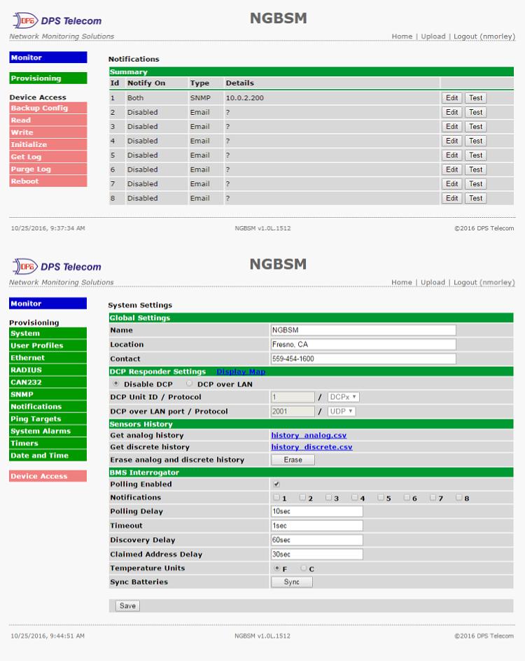
31 System From the Provisioning > System menu, you will configure and edit the global system, call, T/Mon and control settings for the NetGuardian BSM. The Provisioning > System menu Name Location Contact TRIP Unit ID DCP Unit ID DCP Unit Protocol DCP over LAN port LAN Protocol Global System Settings A name for this NetGuardian BSM unit. {Optional field) The location of this NetGuardian BSM unit. {Optional field) Contact telephone number for the person responsible for this NetGuardian BSM unit. {Optional field) Site number used when communicating over dialup with T/Mon. DCP Responder Settings (For use with T/Mon) User-definable ID number for the target unit (DCP Address) Drop-down menu of available protocols for use with DCP Address Enter the DCP port for the target unit (UDP/TCP port) Drop-down menu of available protocols for use over LAN
32 BMS Interrogator Polling Enabled Notifications Polling Delay Timeout Discovery Delay Claimed Address Delay Temperature Units CAN Address Sync Batteries BMS Interrogator Check to monitor CAN Network. Report critical alarms via SNMP Trap or (See Section 9.1) Time between polling string of batteries. Default 10 sec. How long BMS has to respond before it is considered not detected. Default 1 sec. How often NetGuardian searches for new batteries added to CAN Network. Default 60 sec. How often NetGuardian checks for batteries going offline. Units to format temperature recordings. Address for this CAN device (usually use default). Saves the serial numbers of all currently connected batteries, click when batteries are added or removed. This action can also be performed by SNMP SET dpsrtusyncreq=1.

33 User Profiles Clicking User Profiles gives you access to modify the default username and password, and to edit the administrator profile and create up to 9 additional unique user profiles, each with different access rights to the NetGuardian BSM's web interface. Configure access privileges for users in the User Profile screen To create or edit any of the 10 user profiles (including the Admin), click the Edit button. From there, you can change all configurable settings for a user profile. User Profile Suspend this Profile If this box is checked, the profile will not be able to access the NetGuardian BSM. Username Enter a username or a user description Password Enter a unique user password Note: All passwords are AES 128 encrypted. Confirm Password Re-enter the password. Access Rights Check all Edit logon profiles Enables all Access Rights Enables the user to add/modify user profiles and password information. Write Config (change unit configuration) Enables the user to change the unit config by accessing the Write feature in the control menu. View monitor pages Allows the user to access Monitor menu options. Send relay commands Allows the user to send commands to operate the device's control relays. TTY access (access via Grants the user access to the unit via TTY interface (via craft or telnet). Craft port or via Telnet) Initialize config to factory defaults Allows the user to use the Initialize option in the Device Access menu, resetting the NetGuardian BSM to factory default settings. All user settings will be lost. Upload new firmware, Allows the user to upload firmware or backed-up configuration files. or config Get audit log Allows the user to access the Audit Log (Get Log command). Purge (delete) audit log Allows the user to deletes the existing audit log. Get (backup) config Backs-up all user profile configuration settings. Get and delete analog Allows the user to access and delete the analog and sensor history. history User profile field descriptions

34 Ethernet The Edit > Ethernet menu allows you to define and configure Ethernet settings. The Provisioning > Ethernet menu MAC Address Host Name Enable DHCP Unit IP Subnet Mask Gateway DNS Server 1 DNS Server 2 Ethernet Settings Hardware address of the NetGuardian BSM. (Not editable - For reference only.) Used only for web browsing. Example: If you don't want to remember this NetGuardian BSM's IP address, you can type in a name is this field, such as "MyNetGuardian BSM". Once you save and reboot the unit, you can now browse to it locally by simply typing in "MyNetGuardian BSM" in the address bar. (no " needed). Used to turn on Dynamic Host Connection Protocol. NOT recommended, because the unit is assigned an IP address from your DHCP server. The IP you've already assigned to the unit becomes inactive. Using DHCP means the unit will NOT operate in a T/Mon environment. IP address of the NetGuardian BSM. A road sign to the NetGuardian BSM, telling it whether your packets should stay on your local network or be forwarded somewhere else on a wide-area network. An important parameter if you are connected to a wide-area network. It tells the NetGuardian BSM which machine is the gateway out of your local network. Set to if not using. Contact your network administrator for this info. Primary IP address of the domain name server. Set to if not using. Secondary IP address of the domain name server. Set to is not using. Advanced TCP Settings The defined TCP window size is used. Force Max TCP Window Size Maximum TCP Sets the TCP receive window size. Window Size Note: DNS Server settings are required if a hostname is being used for ping targets.
, it requests an authentication from the RADIUS server.")
35 RADIUS RADIUS (Remote Authentication Dial In User Service) is an industry-standard way to manage logins to many different types of equipment in one central location. The NetGuardian BSM connects to your central RADIUS server. Every time a device receives a login attempt (usually a username & password), it requests an authentication from the RADIUS server. If the username & password combination is found in the server's database, an affirmative "access granted" reply is sent back to the unit device, allowing the user to connect. Fig RADIUS server prompt for Username and Password. Fig RADIUS configuration screen Retry Time-out IPA Port Secret Global Settings Enter the number of times the RADIUS server should retry a logon attempt Enter in the number of seconds before a logon request is timed out Servers 1 / 2 Enter the IP address of the RADIUS server Port 1812 is an industry-standard port for using RADIUS Enter the RADIUS secret in this field After successfully entering the settings for the RADIUS server, the NetGuardian Web Browser will prompt users for both a Username and Password, which will be verified using the information and access rights stored in the RADIUS database. RADIUS logons are case-sensitive. If the RADIUS server is unavailable or access is denied, the master password will work for craft port access only. Also, the "dictionary.dps" files (included on the Resource Disk) needs to be loaded on the RADIUS server for access-right definition. If RADIUS is enabled on the NetGuardian, the local authentication will not be valid.

36 CAN 232 (G1 only) The Provisioning > CAN 232 menu allows you to change settings depending on the port type of your NetGuardian BSM. From this menu, you can select a mode of operation and enable reach-through serial port functionality. The Provisioning > CAN 232 menu Port Configuration Port Type Choose 232. Baud, Parity, and Stop Bits Choose , 8-bit data, 1 stop bit. RTS Head Choose 0. RTS Tail Choose 0. Reach-Through Use to configure CAN232 converter via telnet session: Enable Reach-Through telnet [IP address] [port] Example: telnet Port Port number used for reach-through. Select TCP or UDP traffic to be passed through to a serial Type device.

37 SNMP The Provisioning > SNMP menu allows you to define and configure the SNMP settings. SNMP Menu Global Settings Get Community Community name for SNMP requests. Set Community Community name for SNMP SET requests. Read and Write Access This field defines how the NetGuardian BSM unit may be accessed via SNMP. This can be set to the following: Access Disabled- Restricts all access to unit via SNMP SNMPv2c only- Allows SNMPv2c access only SNMPv2c and SNMPv1-Only- Allows SNMPv1 and SNMPv2c access SNMPv3, SNMPv2c and SNMPv1- Allows SNMPv3, SNMPv2c and SNMPv1 access SNMPv3 Engine ID Specifies the v3 Engine ID for your NetGuardian device. DPS recommends using the default ID for the unit, which is automatically generated by the unit.the default ID is generated according to RFC3411 and is based on the unit's unique MAC address and DPS Telecom's SNMP enterprise number. Note: To have the unit generate a unique Engine ID, clear the v3 Engine ID field and press the Submit key. Fields in the Provisioning > SNMP settings
 and notification type(s) are defined from this menu.")
38 Alarms (G2 only) If your NetGuardian was built with discrete alarms, they are configured from the Provisioning > Alarms menu. s for the alarm points, polarity (normal or reversed) and notification type(s) are defined from this menu. You also have the option to use Basic or Advanced configuration methods, explained in this section. The Provisioning > Alarms menu ID Rev (Reverse) Notification Devices On Set On Clear Qual. Time (Qualification Time) Qual. Type (Qualification Type) Basic Alarm Configuration Alarm ID number. User-definable description for the discrete alarm point. Reverse: Check this box to reverse the polarity of the alarm point. Leaving this option un-checked means a normally open contact closure is an alarm. When polarity is reversed, a normally closed alarm point is clear when closed. Check which notification device(s), 1 through 8, you want to send alarm notifications for that alarm point. Advanced Alarm Configuration (Advanced>>) User-definable description (condition) that will appear for the discrete alarm input on Set. Example: "Alarm". User-definable description (condition) that will appear for the discrete alarm input on Clear: "Example: "Alarm Cleared". The length of time that must pass, without interruption, in order for the condition to be considered an Alarm or a Clear. Allows you to choose whether you want to apply the Qualification Time to the alarm Set, Clear, or Both.
. The Provisioning > Controls screen Basic Controls Configuration ID number for the control relay.")
39 Controls (G2 only) The NetGuardian BSM G2 has two control relays that can be configured in the Provisioning > Controls menu. You can enter your own description for these relays and designate them to a notification device(s). The Provisioning > Controls screen Basic Controls Configuration ID number for the control relay. User-definable description for the NetGuardian BSM G2's control relay. How long a latch or release lasts when you execute the MOM command in Monitor > Momentary Time Controls. Max limit of 600s or 10m. Check which notification device(s), 1 through 8, you want to send alarm notifications Notification Devices for the control relay. Note: Setting the momentary time will also affect how long the relay will release between each Battery Alarm that is set or cleared for that relay. Read more in (Battery Alarms) or 12.2 (Monitoring Controls). ID
 Notification Devices Provisioning Ping Targets ID number for the ping target. Check this box to enable the ping target.")
40 Ping Targets The Provisioning > Ping Targets menu allows you to configure the, IP Address, and Notification Devices for each of your ping targets. The Provisioning > Ping Targets menu ID Enab Server (IP or Hostname) Notification Devices Provisioning Ping Targets ID number for the ping target. Check this box to enable the ping target. User-definable description for the ping target. IP address or hostname of the device you would like to ping. Check which notification device(s), 1 through 8, you want to send alarm notifications for ping target.
 Silence Notification Devices Relay Map Editing System Alarms The system alarm point number Non-editable description for this System (housekeeping) Alarm.")
41 System Alarms See " Mapping" in the Reference Section for a complete description of system alarms. The Provisioning > System Alarms menu Pnt () Silence Notification Devices Relay Map Editing System Alarms The system alarm point number Non-editable description for this System (housekeeping) Alarm. Check this box to choose to silence this alarm. Check which notification device(s), 1 through 8, you want to send alarm notifications for that alarm point. Configure your system alarm to latch a relay. Note: The NGBSM G2 comes with 3 CAN bus system alarms (CAN RX WARNING, CAN TX WARNING, CAN TX BUS OFF) that will trigger when the CAN transmission error counter or CAN receive error counter exceed certain values, as detailed in CAN specification 2.0b.
 should be latched when an alarm is triggered.")
42 Battery Alarms The Provisioning > Battery Alarms menu allows you to configure which battery states should trigger an alarm, and which relay (if any) should be latched when an alarm is triggered. For each non-configurable alarm point, the drop-down menu allows you to select whether the triggered alarm will latch Relay 1 (signifying a Major alarm), Relay 2 (signifying a Minor alarm), or no relay at all. Provisioning > Battery Alarms
 or minutes (m),")
43 Timers Enter the amount of time in seconds (sec) or minutes (m), in each value field and click Save. The Provisioning > Timers menu
 Enable NTP Check this box to enable Network Time Protocol. Enter the NTP server's IP address or host name, then click Sync. NTP Server Address or Host Name Example: us.")
44 Date and Time The Provisioning > Date and Time menu Unit Time Set today's date. Set the current time. Automatic Time Adjustment (NTP) Enable NTP Check this box to enable Network Time Protocol. Enter the NTP server's IP address or host name, then click Sync. NTP Server Address or Host Name Example: us.pool.ntp.org. Note: Make sure to configure DNS before using host name instead of IP address. Time Zone Select your time zone from the drop-down menu. Adjust Clock for Daylight Savings Time (DST) Enable DST Check this box to have the NetGuardian BSM observe Daylight Savings. Start Day Select the month, weekday, and time when Daylight Savings will begin. End Day Select the month, weekday, and time when Daylight Savings will end. Date Time

45 41 12 Monitoring via the Web Browser 12.1 Alarms (G2 only) This selection provides the status of the base alarms by indicating if an alarm has been triggered. Under the State column, the status will appear in red if an alarm has been activated. The status will be displayed in green when the alarm condition is not present. Click on Alarms in the Monitor menu to see if any base alarms have been triggered. ID State Basic Alarm Monitoring Alarm ID number. User-definable description for the discrete alarm point. The current state of the alarm. (Clear or Alarm)

46 Controls (G2 only) Use the following rules to operate the NetGuardian's control: 1. Select Controls from the Monitor menu. 2. Under the State field, you can see the current condition of the control. 3. To issue the control, click on a command (OPR - operate, RLS - release, or MOM - momentary) By default, Relay 1 is latched by a major battery alarm, and Relay 2 is latched by a minor battery alarm. Manually operating the control will override the current alarm state, but only until the alarm state changes again. Note: If a relay is already latched when a new battery alarm for that relay is triggered, the relay will indicate this by momentarily (MOM) releasing the relay, before latching again. Similarly, if multiple major or minor alarms are triggered, and one of them clears, the relay corresponding to that alarm will MOM release before latching again. View and operate control relays from the Monitor > Controls menu ID State Command Control Relay Operation ID number for the control relay. for the NetGuardian BSM G2's control relay defined in the Provisioning > Controls menu. Status of the control relay. Can either be Released or Latched. OPR - Latch the relay. RLS - Release the relay. MOM - Momentarily latch the relay, then automatically release the relay. The duration of the latch is defined in the Provisioning > Controls menu.


47 Ping Targets Ping Targets can be viewed by going to Monitor > Ping Targets. Here you can view the state (either Clear or Alarm) for each of your configured Ping Targets. View the status of Ping Targets from the Monitor > Ping Targets menu System Alarms System alarms are not-editable, housekeeping alarms that are programmed into NetGuardian BSM and BSMG2. The Monitor > System Alarms screen provides the status of the system alarms by indicating if an alarm has been triggered. Under the State column, the status will appear in red if an alarm has been activated. The status will be displayed in green when the alarm condition is not present. See " Mapping" in the Reference Section for a complete description of system alarms. View the status of System Alarms from the Monitor > System Alarms menu.

48 Battery Alarms Each battery is monitored independently according the non-configurable set of alarms in Provisioning > Battery Alarms. Select a battery to monitor via the drop-down menu in the Monitor > Battery Alarms sidebar on the left. Monitor > Battery 2 Alarms 12.6 Battery Stats The Monitor > Battery Stats display allows you to view the current status of your configured batteries, including their voltage, temperature, and polling success ratio.

49 45 13 Device Access s The Device Access options, listed in pink on the left side of the web interface, provide options for generating reports, updating the NetGuardian BSM's firmware, and rebooting the unit. Click any of the options under Device Access to perform the desired action. The control menu is located in the bottom left of the web interface Device Access Option Backup Config Read Write Initialize Get Log Purge Log Reboot Backs up the units configuration settings Reads a configuration file from the unit Commits all changes made in the web interface to the NetGuardian BSM's non-volatile memory Sets the unit's configuration to factory default values Opens the NetGuardian BSM's event log in Notepad (or another plain text editor). Deletes the NetGuardian BSM's event log history. Reboots the NetGuardian BSM.

50 46 14 Backup Configuration With the NetGuardian BSM you can backup your current configuration from the Web Interface. These configuration files can then be uploaded later, or uploaded to other NetGuardian BSM units. The Back up Config tab is located in the Device Access menu shown above. How to backup your current configuration: 1. Click the Backup Config tab from the Device Access menu. 2. When prompted by your web browser, download the file to your desktop or other location on your computer. 3. Now your configuration should be saved. If you need to upload a configuration, follow the steps below. To upload your configuration file, click on Upload on the top right corner of the web interface How to upload a saved configuration: 1. Click the upload button at the top right corner of the Welcome screen. 2. Click the Browse... button 3. Browse to the location of the.bin file from the steps above. 4. Select that.bin file and press the Upload button. 5. You should now have the same configuration settings loaded from when you saved the.bin file above.
51 47 15 Firmware Upgrade To access the Firmware Load screen, click on the Provisioning > System menu. At the bottom of this screen, click the Restore Configuration link located in the System Controls section. To upload firmware, click on Upload on the top right corner of the web interface At the Firmware Load screen, simply browse for the firmware update you've downloaded from and click Load. Browse for downloaded firmware upgrade
52 48 16 Reference Section 16.1 Mapping Mapping Alarms 1-4 Control Relays 1-4 Default configuration DIP Switch Config MAC Address Not Set IP Address Not Set LAN Hardware Error SNMP Processing Error SNMP community error LAN TX packet drop Notification 1 failed Notification 2 failed Notification 3 failed Notification 4 failed Notification 5 failed Notification 6 failed Notification 7 failed Notification 8 failed NTP failed Timed tick Serial RCV Q Dynamic Mem Full Unit Reset DCP Poll Inactive Trip Error No Dial Tone Modem Failed Too Many Batteries Connected New Battery Detected CAN RX Warning (G2 only) CAN TX Warning (G2 only) CAN TX Bus Off (G2 only) Ping Alarms Battery #1 Serial Number Battery #1 Software Version Battery #1 Software Revision Battery #1 Hardware Revision 1 2 4
53 Battery #1 Type ID Battery #1 Type Switch Setting Battery #1 Firmwre/Hardware Match Battery #1 Not Detected Battery #1 Sent to Sleep Battery #1 Operation Mode: Initializing Battery #1 Operation Mode: Wake-Up Battery #1 Operation Mode: Validating Battery #1 Operation Mode: Post Battery #1 Operation Mode: Normal Battery #1 Operation Mode: Lock-Out Battery #1 In Lock-Out Battery #1 Charge Mode: Initializing Battery #1 Charge Mode: Float Battery #1 Charge Mode: Charge Battery #1 Charge Mode: Discharge Battery #1 Charge Mode: Charge Complete Battery #1 Current: Warning Battery #1 Current: Alarm Battery #1 Current: Lock-Out Battery #1 Temperature: Warning Battery #1 Temperature: Alarm Battery #1 Temperature: Lock-Out Battery #1 Low Voltage: Warning Battery #1 Low Voltage: Alarm Battery #1 Low Voltage: Lock-Out Battery #1 High Voltage: Warning Battery #1 High Voltage: Alarm Battery #1 High Voltage: Lock-Out Battery #1 Current (A) Battery #1 Max Current (A) Battery #1 State of Charge (%) Battery #1 Voltage (VDC) Battery #1 Remaining Capacity (Ahr) Battery #1 Average Cell Temperature ( C/ F) Battery #1 Nominal Float Voltage (VDC) Battery #1 Estimated Runtime (minutes) Battery #1 Design Max Capacity (Ahr) Battery #1 State of Health (%) Battery #1 Number of Complete Discharge Cycles Battery #1 Usable Capacity (Ahr) 1-64 Battery #2 Serial Number
54 Battery #2 Software Version Battery #2 Software Revision Battery #2 Hardware Version Battery #2 Type ID Battery #2 Type Switch Setting Battery #2 Firmware/Hardware Match Battery #2 Not Detected Battery #2 Sent to Sleep Battery #2 Operation Mode: Initializing Battery #2 Operation Mode: Wake-Up Battery #2 Operation Mode: Validating Battery #2 Operation Mode: Post Battery #2 Operation Mode: Normal Battery #2 Operation Mode: Lock-Out Battery #2 In Lock-Out Battery #2 Charge Mode: Initializing Battery #2 Charge Mode: Float Battery #2 Charge Mode: Charge Battery #2 Charge Mode: Discharge Battery #2 Charge Mode: Charge Complete Battery #2 Current: Warning Battery #2 Current: Alarm Battery #2 Current: Lock-Out Battery #2 Temperature: Warning Battery #2 Temperature: Alarm Battery #2 Temperature: Lock-Out Battery #2 Low Voltage: Warning Battery #2 Low Voltage: Alarm Battery #2 Low Voltage: Lock-Out Battery #2 High Voltage: Warning Battery #2 High Voltage: Alarm Battery #2 High Voltage: Lock-Out Battery #2 Current (A) Battery #2 Max Current (A) Battery #2 State of Charge (%) Battery #2 Voltage (VDC) Battery #2 Remaining Capacity (Ahr) Battery #2 Average Cell Temperature ( C/ F) Battery #2 Nominal Float Voltage (VDC) Battery #2 Estimated Runtime (minutes) Battery #2 Design Max Capacity (Ahr) Battery #2 State of Health (%)
55 Battery #2 Number of Complete Discharge Cycles Battery #2 Usable Capacity (Ahr) Battery #3 Serial Number Battery #3 Software Version Battery #3 Software Revision Battery #3 Hardware Version Battery #3 Type ID Battery #3 Type Switch Setting Battery #3 Firmware/Hardware Match Battery #3 Not Detected Battery #3 Sent to Sleep Battery #3 Operation Mode: Initializing Battery #3 Operation Mode: Wake-Up Battery #3 Operation Mode: Validating Battery #3 Operation Mode: Post Battery #3 Operation Mode: Normal Battery #3 Operation Mode: Lock-Out Battery #3 In Lock-Out Battery #3 Charge Mode: Initializing Battery #3 Charge Mode: Float Battery #3 Charge Mode: Charge Battery #3 Charge Mode: Discharge Battery #3 Charge Mode: Charge Complete Battery #3 Current: Warning Battery #3 Current: Alarm Battery #3 Current: Lock-Out Battery #3 Temperature: Warning Battery #3 Temperature: Alarm Battery #3 Temperature: Lock-Out Battery #3 Low Voltage: Warning Battery #3 Low Voltage: Alarm Battery #3 Low Voltage: Lock-Out Battery #3 High Voltage: Warning Battery #3 High Voltage: Alarm Battery #3 High Voltage: Lock-Out Battery #3 Current (A) Battery #3 Max Current (A) Battery #3 State of Charge (%) Battery #3 Voltage (VDC) Battery #3 Remaining Capacity (Ahr) Battery #3 Average Cell Temperature ( C/ F) Battery #3 Nominal Float Voltage (VDC)
56 52 Battery #3 Estimated Runtime (minutes) Battery #3 Design Max Capacity (Ahr) Battery #3 State of Health (%) Battery #3 Number of Complete Discharge Cycles Battery #3 Usable Capacity (Ahr) Battery #4 Serial Number Battery #4 Software Version Battery #4 Software Revision Battery #4 Hardware Revision Battery #4 Type ID Battery #4 Type Switch Setting Battery #4 Firmwre/Hardware Match Battery #4 Not Detected Battery #4 Sent to Sleep Battery #4 Operation Mode: Initializing Battery #4 Operation Mode: Wake-Up Battery #4 Operation Mode: Validating Battery #4 Operation Mode: Post Battery #4 Operation Mode: Normal Battery #4 Operation Mode: Lock-Out Battery #4 In Lock-Out Battery #4 Charge Mode: Initializing Battery #4 Charge Mode: Float Battery #4 Charge Mode: Charge Battery #4 Charge Mode: Discharge Battery #4 Charge Mode: Charge Battery #4 Current: Warning Battery #4 Current: Alarm Battery #4 Current: Lock-Out Battery #4 Temperature: Warning Battery #4 Temperature: Alarm Battery #4 Temperature: Lock-Out Battery #4 Low Voltage: Warning Battery #4 Low Voltage: Alarm Battery #4 Low Voltage: Lock-Out Battery #4 High Voltage: Warning Battery #4 High Voltage: Alarm Battery #4 High Voltage: Lock-Out Battery #4 Current (A) Battery #4 Max Current (A) Battery #4 State of Charge (%) Battery #4 Voltage (VDC)
57 Battery #4 Remaining Capacity (Ahr) Battery #4 Average Cell Temperature ( C/ F) Battery #4 Nominal Float Voltage (VDC) Battery #4 Estimated Runtime (minutes) Battery #4 Design Max Capacity (Ahr) Battery #4 State of Health (%) Battery #4 Number of Complete Discharge Cycles Battery #4 Usable Capacity (Ahr) Battery #5 Serial Number Battery #5 Software Version Battery #5 Software Revision Battery #5 Hardware Version Battery #5 Type ID Battery #5 Type Switch Setting Battery #5 Firmware/Hardware Match Battery #5 Not Detected Battery #5 Sent to Sleep Battery #5 Operation Mode: Initializing Battery #5 Operation Mode: Wake-Up Battery #5 Operation Mode: Validating Battery #5 Operation Mode: Post Battery #5 Operation Mode: Normal Battery #5 Operation Mode: Lock-Out Battery #5 In Lock-Out Battery #5 Charge Mode: Initializing Battery #5 Charge Mode: Float Battery #5 Charge Mode: Charge Battery #5 Charge Mode: Discharge Battery #5 Charge Mode: Charge Complete Battery #5 Current: Warning Battery #5 Current: Alarm Battery #5 Current: Lock-Out Battery #5 Temperature: Warning Battery #5 Temperature: Alarm Battery #5 Temperature: Lock-Out Battery #5 Low Voltage: Warning Battery #5 Low Voltage: Alarm Battery #5 Low Voltage: Lock-Out Battery #5 High Voltage: Warning Battery #5 High Voltage: Alarm Battery #5 High Voltage: Lock-Out
58 Battery #5 Current (A) Battery #5 Max Current (A) Battery #5 State of Charge (%) Battery #5 Voltage (VDC) Battery #5 Remaining Capacity (Ahr) Battery #5 Average Cell Temperature ( C/ F) Battery #5 Nominal Float Voltage (VDC) Battery #5 Estimated Runtime (minutes) Battery #5 Design Max Capacity (Ahr) Battery #5 State of Health (%) Battery #5 Number of Complete Discharge Cycles Battery #5 Usable Capacity (Ahr) Battery #6 Serial Number Battery #6 Software Version Battery #6 Software Revision Battery #6 Hardware Version Battery #6 Type ID Battery #6 Type Switch Setting Battery #6 Firmware/Hardware Match Battery #6 Not Detected Battery #6 Sent to Sleep Battery #6 Operation Mode: Initializing Battery #6 Operation Mode: Wake-Up Battery #6 Operation Mode: Validating Battery #6 Operation Mode: Post Battery #6 Operation Mode: Normal Battery #6 Operation Mode: Lock-Out Battery #6 In Lock-Out Battery #6 Charge Mode: Initializing Battery #6 Charge Mode: Float Battery #6 Charge Mode: Charge Battery #6 Charge Mode: Discharge Battery #6 Charge Mode: Charge Complete Battery #6 Current: Warning Battery #6 Current: Alarm Battery #6 Current: Lock-Out Battery #6 Temperature: Warning Battery #6 Temperature: Alarm Battery #6 Temperature: Lock-Out Battery #6 Low Voltage: Warning Battery #6 Low Voltage: Alarm Battery #6 Low Voltage: Lock-Out
59 Battery #6 High Voltage: Warning Battery #6 High Voltage: Alarm Battery #6 High Voltage: Lock-Out Battery #6 Current (A) Battery #6 Max Current (A) Battery #6 State of Charge (%) Battery #6 Voltage (VDC) Battery #6 Remaining Capacity (Ahr) Battery #6 Average Cell Temperature ( C/ F) Battery #6 Nominal Float Voltage (VDC) Battery #6 Estimated Runtime (minutes) Battery #6 Design Max Capacity (Ahr) Battery #6 State of Health (%) Battery #6 Number of Complete Discharge Cycles Battery #6 Usable Capacity (Ahr) Battery #7 Serial Number Battery #7 Software Version Battery #7 Software Revision Battery #7 Hardware Revision Battery #7 Type ID Battery #7 Type Switch Setting Battery #7 Firmwre/Hardware Match Battery #7 Not Detected Battery #7 Sent to Sleep Undefine7 Battery #7 Operation Mode: Initializing Battery #7 Operation Mode: Wake-Up Battery #7 Operation Mode: Validating Battery #7 Operation Mode: Post Battery #7 Operation Mode: Normal Battery #7 Operation Mode: Lock-Out Battery #7 In Lock-Out Battery #7 Charge Mode: Initializing Battery #7 Charge Mode: Float Battery #7 Charge Mode: Charge Battery #7 Charge Mode: Discharge Battery #7 Charge Mode: Charge Battery #7 Current: Warning Battery #7 Current: Alarm Battery #7 Current: Lock-Out
60 Battery #7 Temperature: Warning Battery #7 Temperature: Alarm Battery #7 Temperature: Lock-Out Battery #7 Low Voltage: Warning Battery #7 Low Voltage: Alarm Battery #7 Low Voltage: Lock-Out Battery #7 High Voltage: Warning Battery #7 High Voltage: Alarm Battery #7 High Voltage: Lock-Out Battery #7 Current (A) Battery #7 Max Current (A) Battery #7 State of Charge (%) Battery #7 Voltage (VDC) Battery #7 Remaining Capacity (Ahr) Battery #7 Average Cell Temperature ( C/ F) Battery #7 Nominal Float Voltage (VDC) Battery #7 Estimated Runtime (minutes) Battery #7 Design Max Capacity (Ahr) Battery #7 State of Health (%) Battery #7 Number of Complete Discharge Cycles Battery #7 Usable Capacity (Ahr) Battery #8 Serial Number Battery #8 Software Version Battery #8 Software Revision Battery #8 Hardware Version Battery #8 Type ID Battery #8 Type Switch Setting Battery #8 Firmware/Hardware Match Battery #8 Not Detected Battery #8 Sent to Sleep Battery #8 Operation Mode: Initializing Battery #8 Operation Mode: Wake-Up Battery #8 Operation Mode: Validating Battery #8 Operation Mode: Post Battery #8 Operation Mode: Normal Battery #8 Operation Mode: Lock-Out Battery #8 In Lock-Out Battery #8 Charge Mode: Initializing Battery #8 Charge Mode: Float Battery #8 Charge Mode: Charge
61 Battery #8 Charge Mode: Discharge Battery #8 Charge Mode: Charge Complete Battery #8 Current: Warning Battery #8 Current: Alarm Battery #8 Current: Lock-Out Battery #8 Temperature: Warning Battery #8 Temperature: Alarm Battery #8 Temperature: Lock-Out Battery #8 Low Voltage: Warning Battery #8 Low Voltage: Alarm Battery #8 Low Voltage: Lock-Out Battery #8 High Voltage: Warning Battery #8 High Voltage: Alarm Battery #8 High Voltage: Lock-Out Battery #8 Current (A) Battery #8 Max Current (A) Battery #8 State of Charge (%) Battery #8 Voltage (VDC) Battery #8 Remaining Capacity (Ahr) Battery #8 Average Cell Temperature ( C/ F) Battery #8 Nominal Float Voltage (VDC) Battery #8 Estimated Runtime (minutes) Battery #8 Design Max Capacity (Ahr) Battery #8 State of Health (%) Battery #8 Number of Complete Discharge Cycles Battery #8 Usable Capacity (Ahr) Battery #9 Serial Number Battery #9 Software Version Battery #9 Software Revision Battery #9 Hardware Version Battery #9 Type ID Battery #9 Type Switch Setting Battery #9 Firmware/Hardware Match Battery #9 Not Detected Battery #9 Sent to Sleep Battery #9 Operation Mode: Battery #9 Operation Mode: Battery #9 Operation Mode: Battery #9 Operation Mode: Battery #9 Operation Mode: Initializing Wake-Up Validating Post Normal
62 Battery #9 Operation Mode: Lock-Out Battery #9 In Lock-Out Battery #9 Charge Mode: Initializing Battery #9 Charge Mode: Float Battery #9 Charge Mode: Charge Battery #9 Charge Mode: Discharge Battery #9 Charge Mode: Charge Complete Battery #9 Current: Warning Battery #9 Current: Alarm Battery #9 Current: Lock-Out Battery #9 Temperature: Warning Battery #9 Temperature: Alarm Battery #9 Temperature: Lock-Out Battery #9 Low Voltage: Warning Battery #9 Low Voltage: Alarm Battery #9 Low Voltage: Lock-Out Battery #9 High Voltage: Warning Battery #9 High Voltage: Alarm Battery #9 High Voltage: Lock-Out Battery #9 Current (A) Battery #9 Max Current (A) Battery #9 State of Charge (%) Battery #9 Voltage (VDC) Battery #9 Remaining Capacity (Ahr) Battery #9 Average Cell Temperature ( C/ F) Battery #9 Nominal Float Voltage (VDC) Battery #9 Estimated Runtime (minutes) Battery #9 Design Max Capacity (Ahr) Battery #9 State of Health (%) Battery #9 Number of Complete Discharge Cycles Battery #9 Usable Capacity (Ahr) Battery #10 Serial Number Battery #10 Software Version Battery #10 Software Revision Battery #10 Hardware Revision Battery #10 Type ID Battery #10 Type Switch Setting Battery #10 Firmwre/Hardware Match Battery #10 Not Detected Battery #10 Sent to Sleep
63 Battery #10 Operation Mode: Initializing Battery #10 Operation Mode: Wake-Up Battery #10 Operation Mode: Validating Battery #10 Operation Mode: Post Battery #10 Operation Mode: Normal Battery #10 Operation Mode: Lock-Out Battery #10 In Lock-Out Battery #10 Charge Mode: Initializing Battery #10 Charge Mode: Float Battery #10 Charge Mode: Charge Battery #10 Charge Mode: Discharge Battery #10 Charge Mode: Charge Battery #10 Current: Warning Battery #10 Current: Alarm Battery #10 Current: Lock-Out Battery #10 Temperature: Warning Battery #10 Temperature: Alarm Battery #10 Temperature: Lock-Out Battery #10 Low Voltage: Warning Battery #10 Low Voltage: Alarm Battery #10 Low Voltage: Lock-Out Battery #10 High Voltage: Warning Battery #10 High Voltage: Alarm Battery #10 High Voltage: Lock-Out Battery #10 Current (A) Battery #10 Max Current (A) Battery #10 State of Charge (%) Battery #10 Voltage (VDC) Battery #10 Remaining Capacity (Ahr) Battery #10 Average Cell Temperature ( C/ F) Battery #10 Nominal Float Voltage (VDC) Battery #10 Estimated Runtime (minutes) Battery #10 Design Max Capacity (Ahr) Battery #10 State of Health (%) Battery #10 Number of Complete Discharge Cycles Battery #10 Usable Capacity (Ahr)
64 System Alarms 1 33 Default Configuration 34 DIP Switch Configuration 35 MAC Address Not Set 36 IP Address Not Set 37 LAN hardware error 38 SNMP Process Error 39 SNMP Community Error 40 LAN TX packet drop 41 Notification 1 Failed 42 Notification 2 Failed 43 Notification 3 Failed 44 Notification 4 Failed 45 Notification 5 Failed 46 Notification 6 Failed 47 Notification 7 Failed 48 Notification 8 failed 49 NTP Failed 50 Timed Tick 51 Serial 1 RcvQ full 52 Dynamic Memory Full 53 Unit Reset 54 DCP Poller inactive 55 Trip Error 56 No Dial Tone 57 Modem Failed 58 Too Many Batteries Connected 59 New Battery Detected 60 CAN RX WARNING 61 CAN TX WARNING 62 CAN TX BUS OFF System Alarms
65 SNMP Manager Functions The SNMP Manager allows the user to view alarm status, set date/time, issue controls, and perform a resync. The display and tables below outline the MIB object identifiers. The table below begins with dpsrtu; however, the MIB object identifier tree has several levels above it. The full English name is as follows: root.iso.org.dod.internet.private.enterprises.dps-inc.dpsalarmcontrol.dpsrtu. Therefore, dpsrtu's full object identifier is Each level beyond dpsrtu adds another object identifying number. For example, the object identifier of the portion of the Control Grid is because the object identifier of dpsrtu is the Control Grid (.3) + the (.3). Tbl. B1 (O.)_OV_Traps points _OV_vTraps ( ) Tbl. B2 (.1) Identity points Ident ( ) Tbl. B3 (.2) Grid points Manufacturer (.1) Entry ( ) Set (.20) Model (.2) Port (.1) Clr (.21) Firmware Version (.3) Address (.2) SumPSet (.101) DateTime (.4) (.3) SumPClr (.102) ResyncReq (.5)* DispDesc (.4)* ComFailed (.103) * Must be set to "1" to perform the resync request which will resend TRAPs for any standing alarm. PntMap (.5)* ComRestored (.014) P0001Set (.10001) through P0064Set (.10064) P0001Clr (.20001) through P0064Clr (.20064) Tbl. B3 (.3) ControlGrid points ControlGrid ( ) Tbl. B6 (.6) Analog Channels Channel Entry ( ) Tbl. B5 (.5) AlarmEntry points Channel Number (.1) AlarmEntry ( ) Port (.1) Enabled (.2) Aport (.1) Address (.2) (.3) AAddress (.2) (.3) Value (.4) A (.3) (.4) Thresholds (.5)* A (.4) Action (.5) *If Mj, Mn is assumed APntDesc (.5)* AState (.6) * For specific alarm points, see Table B6
66 SNMP Granular Trap Packets The tables below provide a list of the information contained in the SNMP Trap packets sent by the NetGuardian BSM. SNMP Trap managers can use one of two methods to get alarm information: 1. Granular traps (not necessary to define point descriptions for the NetGuardian BSM) OR 2. The SNMP manager reads the description from the Trap. UDP Header 1238 Source port 162 Destination port 303 Length 0xBAB0 Checksum UDP Headers and descriptions SNMP Header 0 Version Public Request Trap Request Enterprise Agent address Enterprise Specific Generic Trap 8001 Specific Trap Time stamp Object NetGuardian DIN v1.0k Value Object Value Object :08: Value Object 99 Value Object 1 Value Object 1 Value Object 1 Value Object Rectifier Failure Value Object Alarm Value SNMP Headers and descriptions
67 63 17 Frequently Asked Questions Here are answers to some common questions from NetGuardian BSM users. The latest FAQs can be found on the NetGuardian BSM support web page, If you have a question about the NetGuardian BSM, please call us at (559) or us at support@dpstele.com General FAQs Q. How do I telnet to the NetGuardian BSM? A. You must use Port 2002 to connect to the NetGuardian BSM. Configure your Telnet client to connect using TCP/IP (not "Telnet," or any other port options). For connection information, enter the IP address of the NetGuardian BSM and Port For example, to connect to the NetGuardian BSM using the standard Windows Telnet client, click Start, click Run, and type "telnet <NetGuardian BSM IP address> 2002." Q. How do I connect my NetGuardian BSM to the LAN? A. To connect your NetGuardian BSM to your LAN, you need to configure the unit IP address, the subnet mask and the default gateway. A sample configuration could look like this: Unit Address: subnet mask: Default Gateway: Save your changes by writing to NVRAM and reboot. Any change to the unit's IP configuration requires a reboot. Q. When I connect to the NetGuardian BSM through the craft port on the front panel it either doesn't work right or it doesn't work at all. What's going on? A. Make sure your using the right COM port settings. Your COM port settings should read: Bits per second: 9600 (9600 baud) Data bits: 8 Parity: None Stop bits: 1 Flow control: None Important! Flow control must be set to none. Flow control normally defaults to hardware in most terminal programs, and this will not work correctly with the NetGuardian BSM. Q. The LAN link LED is green on my NetGuardian BSM, but I can't poll it from my T/Mon. A. Some routers will not forward packets to an IP address until the MAC address of the destination device has been registered on the router's Address Resolution Protocol (ARP) table. Enter the IP address of your gateway and your T/Mon system to the ARP table.
68 SNMP FAQs Q. Which version of SNMP is supported by the SNMP agent on the NetGuardian BSM? A. SNMP v1, SNMPv2 and SNMPv3. Q. How do I configure the NetGuardian BSM to send traps to an SNMP manager? Is there a separate MIB for the NetGuardian BSM? How many SNMP managers can the agent send traps to? And how do I set the IP address of the SNMP manager and the community string to be used when sending traps? A. The NetGuardian BSM begins sending traps as soon as the SNMP notification type is set up. The NetGuardian BSM MIB can be found on the DPS Telecom website. The MIB should be compiled on your SNMP manager. (Note: MIB versions may change in the future.) For step-by-step instructions, refer back to the "How to Send SNMP Traps" section of the user manual. Q. Does the NetGuardian BSM support MIB-2 and/or any other standard MIBs? A. The NetGuardian BSM supports the bulk of MIB-2. Q. Does the NetGuardian BSM SNMP agent support both NetGuardian BSM and T/MonXM variables? A. The NetGuardian BSM SNMP agent manages an embedded MIB that supports only the NetGuardian BSM's RTU variables. The T/MonXM variables are included in the distributed MIB only to provide SNMP managers with a single MIB for all DPS Telecom products. Q. How many traps are triggered when a single point is set or cleared? The MIB defines traps like "major alarm set/cleared," "RTU point set," and a lot of granular traps, which could imply that more than one trap is sent when a change of state occurs on one point. A. Generally, a single change of state generates a single trap. Q. What does "point map" mean? A. A point map is a single MIB leaf that presents the current status of a 64-alarm-point display in an ASCII-readable form, where a "." represents a clear and an "x" represents an alarm. Q. How can I associate descriptive information with a point for the RTU granular traps? A. The NetGuardian BSM alarm point descriptions are individually defined using the Web Browser. Q. My SNMP traps aren't getting through. What should I try? A. Try these three steps: 1. Make sure that the Trap Address (IP address of the SNMP manager) is defined. (If you changed the Trap Address, make sure you saved the change to NVRAM and rebooted.) 2. Make sure all alarm points are configured to send SNMP traps. 3. Make sure the NetGuardian BSM and the SNMP manager are both on the network. Use the unit's ping command to ping the SNMP manager.
69 65 18 Technical Support DPS Telecom products are backed by our courteous, friendly Technical Support representatives, who will give you the best in fast and accurate customer service. To help us help you better, please take the following steps before calling Technical Support: 1. Check the DPS Telecom website. You will find answers to many common questions on the DPS Telecom website, at support/. Look here first for a fast solution to your problem. 2. Prepare relevant information. Having important information about your DPS Telecom product in hand when you call will greatly reduce the time it takes to answer your questions. If you do not have all of the information when you call, our Technical Support representatives can assist you in gathering it. Please write the information down for easy access. Please have your user manual and hardware serial number ready. 3. Have access to troubled equipment. Please be at or near your equipment when you call DPS Telecom Technical Support. This will help us solve your problem more efficiently. 4. Call during Customer Support hours. Customer support hours are Monday through Friday, from 7 A.M. to 6 P.M., Pacific time. The DPS Telecom Technical Support phone number is (559) Emergency Assistance: Emergency assistance is available 24 hours a day, 7 days a week. For emergency assistance after hours, allow the phone to ring until it is answered with a paging message. You will be ask ed to enter your phone number. An on-call technical support representative will return your call as soon as possible.
70 66 19 End User License Agreement All Software and firmware used in, for, or in connection with the Product, parts, subsystems, or derivatives thereof, in whatever form, including, without limitation, source code, object code and microcode, including any computer programs and any documentation relating to or describing such Software is furnished to the End User only under a non-exclusive perpetual license solely for End User's use with the Product. The Software may not be copied or modified, in whole or in part, for any purpose whatsoever. The Software may not be reverse engineered, compiled, or disassembled. No title to or ownership of the Software or any of its parts is transferred to the End User. Title to all patents, copyrights, trade secrets, and any other applicable rights shall remain with the DPS Telecom. DPS Telecom's warranty and limitation on its liability for the Software is as described in the warranty information provided to End User in the Product Manual. End User shall indemnify DPS Telecom and hold it harmless for and against any and all claims, damages, losses, costs, expenses, obligations, liabilities, fees and costs and all amounts paid in settlement of any claim, action or suit which may be asserted against DPS Telecom which arise out of or are related to the non-fulfillment of any covenant or obligation of End User in connection with this Agreement. This Agreement shall be construed and enforced in accordance with the laws of the State of California, without regard to choice of law principles and excluding the provisions of the UN Convention on Contracts for the International Sale of Goods. Any dispute arising out of the Agreement shall be commenced and maintained only in Fresno County, California. In the event suit is brought or an attorney is retained by any party to this Agreement to seek interpretation or construction of any term or provision of this Agreement, to enforce the terms of this Agreement, to collect any money due, or to obtain any money damages or equitable relief for breach, the prevailing party shall be entitled to recover, in addition to any other available remedy, reimbursement for reasonable attorneys' fees, court costs, costs of investigation, and other related expenses.
71 Warranty DPS Telecom warrants, to the original purchaser only, that its products a) substantially conform to DPS' published specifications and b) are substantially free from defects in material and workmanship. This warranty expires two years from the date of product delivery with respect to hardware and ninety days from the date of product delivery with respect to software. If the purchaser discovers within these periods a failure of the product to substantially conform to the specifications or that the product is not substantially free from defects in material and workmanship, the purchaser must promply notify DPS. Within reasonable time after notification, DPS will endeavor to correct any substantial non-conformance with the specifications or substantial defects in material and workmanship, with new or used replacement parts. All warranty service will be performed at the company's office in Fresno, California, at no charge to the purchaser, other than the cost of shipping to and from DPS, which shall be the responsiblity of the purchaser. If DPS is unable to repair the product to conform to the warranty, DPS will provide at its option one of the following: a replacement product or a refund of the purchase price for the non-conforming product. These remedies are the purchaser's only remedies for breach of warranty. Prior to initial use the purchaser shall have determined the suitability of the product for its intended use. DPS does not warrant a) any product, components or parts not manufactured by DPS, b) defects caused by the purchaser's failure to provide a suitable installation environment for the product, c) damage caused by use of the product for purposes other than those for which it was designed, d) damage caused by disasters such as fire, flood, wind or lightning unless and to the extent that the product specification provides for resistance to a defined disaster, e) damage caused by unauthorized attachments or modifications, f) damage during shipment from the purchaser to DPS, or g) any abuse or misuse by the purchaser. THE FOREGOING WARRANTIES ARE IN LIEU OF ALL OTHER WARRANTIES, EXPRESS OR IMPLIED, INCLUDING BUT NOT LIMITED TO THE IMPLIED WARRANTIES OF MERCHANTABILITY AND FITNESS FOR A PARTICULAR PURPOSE. In no event will DPS be liable for any special, incidental, or consequential damages based on breach of warranty, breach of contract, negligence, strict tort, or any other legal theory. Damages that DPS will not be responsible for include but are not limited to, loss of profits; loss of savings or revenue; loss of use of the product or any associated equipment; cost of capital; cost of any substitute equipment, facilities or services; downtime; claims of third parties including customers; and injury to property. The purchaser shall fill out the requested information on the Product Warranty Card and mail the card to DPS. This card provides information that helps DPS make product improvements and develop new products. For an additional fee DPS may, at its option, make available by written agreement only an extended warranty providing an additional period of time for the applicability of the standard warranty. Technical Support If a purchaser believes that a product is not operating in substantial conformance with DPS' published specifications or there appear to be defects in material and workmanship, the purchaser should contact our technical support representatives. If the problem cannot be corrected over the telephone and the product and problem are covered by the warranty, the technical support representative will authorize the return of the product for service and provide shipping information. If the product is out of warranty, repair charges will be quoted. All non-warranty repairs receive a 90-day warranty.


72 Free Tech Support is Only a Click Away Need help with your alarm monitoring? DPS Information Services are ready to serve you in your or over the Web! Free Tech Support in Your The Protocol Alarm Monitoring Ezine The Protocol Alarm Monitoring Ezine is your free tech support alert, delivered directly to your in-box every two weeks. Every issue has news you can use right away: Expert tips on using your alarm monitoring equipment advanced techniques that will save you hours of work Educational White Papers deliver fast informal tutorials on SNMP, ASCII processing, TL1 and other alarm monitoring technologies New product and upgrade announcements keep you up to date with the latest technology Exclusive access to special offers for DPS Telecom Factory Training, product upgrade offers and discounts To get your free subscription to The Protocol register online at Free Tech Support on the Web: MyDPS MyDPS is your personalized, members-only online resource. Registering for MyDPS is fast, free, and gives you exclusive access to: Firmware and software downloads and upgrades Product manuals Product datasheets Exclusive user forms Register for MyDPS online at (800) E. Yale Avenue, Fresno, California 93727
NetGuardian 480/432 G3 & G4
 NetGuardian 480/432 G3 & G4 USER MANUAL D-PK-NG480 D-PK-NG432 Visit our website at www.dpstelecom.com for the latest PDF manual and FAQs. October 28, 206 D-UM-NG480/NG432 Firmware Version 2.0N Revision
NetGuardian LPG Controller
 NetGuardian LPG Controller USER MANUAL D-PK-NGLPG Visit our website at www.dpstelecom.com for the latest PDF manual and FAQs. June 3, 205 D-UM-NGLPG Firmware Version.0A Revision History June 3, 205 Initial
NetGuardian DIN/ NetDog DIN
 NetGuardian DIN/ NetDog DIN USER MANUAL D-PK-NGDIN Visit our website at www.dpstelecom.com for the latest PDF manual and FAQs. July 2, 2018 D-UM-NGDIN Firmware Version 1.0A Revision History July 2, 2018
NetGuardian V16/M16 G2
 NetGuardian V6/M6 G2 USER MANUAL D-PK-26V2 D-PK-M6G2 D-PK-C6V2 Visit our website at www.dpstelecom.com for the latest PDF manual and FAQs. September 26, 206 D-UM-26V2 Firmware Version.0S Revision History
NetGuardian 480 G4 USER MANUAL. Visit our website at for the latest PDF manual and FAQs.
 NetGuardian 480 G4 USER MANUAL Visit our website at www.dpstelecom.com for the latest PDF manual and FAQs. June 2, 203 D-UM-NG480 Firmware Version.F Revision History June 2, 203 Initial Release This document
Discrete Point Module (DPM) 216 G2
 216 G2") Discrete Point Module (DPM) 26 G2 USER MANUAL Visit our website at www.dpstelecom.com for the latest PDF manual and FAQs. December 8, 200 D-OC-UM0C.800 Firmware Version.0A Revision History May 27, 20 Misc
Discrete Point Module (DPM) 26 G2 USER MANUAL Visit our website at www.dpstelecom.com for the latest PDF manual and FAQs. December 8, 200 D-OC-UM0C.800 Firmware Version.0A Revision History May 27, 20 Misc
Remote Power Switch (DC)
") Remote Power Switch (DC) USER MANUAL Visit our website at www.dpstelecom.com for the latest PDF manual and FAQs. November 0, 207 D-UM-26RP-200 Firmware Version.0J.083 Revision History November 0, 207 Added
Remote Power Switch (DC) USER MANUAL Visit our website at www.dpstelecom.com for the latest PDF manual and FAQs. November 0, 207 D-UM-26RP-200 Firmware Version.0J.083 Revision History November 0, 207 Added
Alarm Panel [ PRELIMINARY HARDWARE MANUAL ] USER MANUAL. v1.0a. May 7, 2008 D-OC-UM
![Alarm Panel [ PRELIMINARY HARDWARE MANUAL ] USER MANUAL. v1.0a. May 7, 2008 D-OC-UM](/thumbs/86/93788073.jpg "Alarm Panel [ PRELIMINARY HARDWARE MANUAL ] USER MANUAL. v1.0a. May 7, 2008 D-OC-UM") Alarm Panel USER MANUAL [ PRELIMINARY HARDWARE MANUAL ] Visit our website at www.dpstelecom.com for the latest PDF manual and FAQs. May 7, 2008 D-OC-UM085.07010 v1.0a Revision History April 28, 2008 May
Alarm Panel USER MANUAL [ PRELIMINARY HARDWARE MANUAL ] Visit our website at www.dpstelecom.com for the latest PDF manual and FAQs. May 7, 2008 D-OC-UM085.07010 v1.0a Revision History April 28, 2008 May
G2 USER MANUAL D-PK-TDFG2
 TempDefender G2 USER MANUAL D-PK-TDFG2 Visit our website at www.dpstelecom.com for the latest PDF manual and FAQs. May 3, 208 D-UM-TDFG2 Firmware Version 2.0A Revision History M ay 3, 208 Added High-Security
NetGuardian 216 G3 USER MANUAL. Visit our website at for the latest PDF manual and FAQs.
 NetGuardian 26 G3 USER MANUAL Visit our website at www.dpstelecom.com for the latest PDF manual and FAQs. February 9, 202 D-UM-NG26-200 Firmware Version 2.0K Revision History February 9, 202 Added Verizon
NetGuardian. and other RTUs
 NetGuardian and other RTUs 2 Factory Training Workbook NetGuardian Contents The NetGuardian 832A G5 NGEdit Software NetGuardian Hardware NetGuardian Setup NetGuardian Provisioning and Monitoring Troubleshooting
IndigoVision Alarm Panel. User Guide
 IndigoVision Alarm Panel User Guide THIS MANUAL WAS CREATED ON 2/21/2017. DOCUMENT ID: IU-AP-MAN002-4 Legal considerations LAWS THAT CAN VARY FROM COUNTRY TO COUNTRY MAY PROHIBIT CAMERA SURVEILLANCE. PLEASE
Model 135 Reference Document
 Model 135 Reference Document 2007 by Gordon Kapes, Inc. all rights reserved 5520 West Touhy Avenue Skokie, Illinois 60077 USA Telephone 847 676-1750 Fax 847 982-0747 www.gkinc.com 40218, Issue 1 January
Alarm Client. Installation and User Guide. NEC NEC Corporation. May 2009 NDA-30364, Revision 9
 Alarm Client Installation and User Guide NEC NEC Corporation May 2009 NDA-30364, Revision 9 Liability Disclaimer NEC Corporation reserves the right to change the specifications, functions, or features,
Installation, Configuration and User Manual
 Model 8826 System Controller Model 8826 System Controller Installation, Configuration and User Manual READ AND SAVE THESE INSTRUCTIONS WELCOME Thank you for choosing the Aprilaire HVAC Automation System.
Operation Manual Fighter ProVision Software. Version: 0.0 Revision: 1
 Operation Manual Fighter ProVision Software Version: 0.0 Revision: 1 TABLE OF CONTENTS 1. Introduction 5 2. Software Installation 5 3. PC Users 6 3.1 Introduction 6 3.2 Default Code 6 3.3 Edit PC User
Installation Manual. ATS Remote Annunciator Catalog 5350 DANGER WARNING D
 ASCO 5350 The ASCO 5350 ATS Remote Annunciator is listed under the Underwriter s Laboratories Standard UL-1008 for Automatic Transfer Switch accessories. This stand-alone device provides individual status
MultiSite Manager. Setup Guide
 MultiSite Manager Setup Guide Contents 1. Introduction... 2 How MultiSite Manager works... 2 How MultiSite Manager is implemented... 2 2. MultiSite Manager requirements... 3 Operating System requirements...
Quick Alert Remote (QA216R)
") Quick Alert Remote (QA216R) Description The QA 216 Remote is used by AT&T to monitor tower lights and turned down facilities. It is a 16-bit alarm unit used to transport discrete alarms from a remote location
Quick Alert Remote (QA216R) Description The QA 216 Remote is used by AT&T to monitor tower lights and turned down facilities. It is a 16-bit alarm unit used to transport discrete alarms from a remote location
PWM. Solar Charge controller with Ethernet. Solar Smart PWM 20Amp. Hardware Description : Release : 19 June 2014
 Solar Charge controller with Ethernet Release : 19 June 2014 Hardware Version : Version 1 Firmware version 1 PC Application Software : Version 1.0.0.0 Hardware Description : The Solar Smart regulator was
Added password for IP setup page : Password must be in IP format!
 NETWORK POWER MONITOR Release : 21 August 2014 Hardware Version : Version 7 Firmware version 1.00 PC Application Software : Version (latest)...2 Added password for IP setup page : Password must be in IP
ibox Modbus Server Gateway for the integration of Notifier ID3000 / ID3002 / ID60 / ID50 fire panels in Modbus enabled monitoring and control systems
 Honeywell Life Safety Iberia C/Pau Vila 15-19; 08911 Badalona Barcelona T. 902 03 05 45; Internacional:+34932424236 www.honeywelllifesafety.es infohlsiberia@honeywell.com ibox Modbus Server Gateway for
AK-CS On Board Guide
 MAKING MODERN LIVING POSSIBLE AK-CS On Board Guide electronic controls & sensors About this guide The AK-CS On Board guide highlights the use of the RMT tool, allowing remote software management. Consult
ICT180S-12I INTELLIGENT MODEL (SERIES 2)
") The Power of Reliability ICT180S-12I INTELLIGENT MODEL (SERIES 2) INSTRUCTION MANUAL TABLE OF CONTENTS Warnings Page 2 Product Description Page 3 Installation Page 4 LCD/Select Button Operation Page 7
The Power of Reliability ICT180S-12I INTELLIGENT MODEL (SERIES 2) INSTRUCTION MANUAL TABLE OF CONTENTS Warnings Page 2 Product Description Page 3 Installation Page 4 LCD/Select Button Operation Page 7
Instruction Manual Environmental Monitoring Unit with Output Relay
 Instruction Manual Environmental Monitoring Unit with Output Relay Watchdog 100 Series Firmware Version 3 Geist. 1821 Yolande Ave., Lincoln, NE 68521 800.432.3219 402.474.3400 F: 402.474.4369 www.geistglobal.com
Simplex Panel Interface Guide
 Simplex Panel Interface Guide February 2016 SATEON Software Integrations Simplex Panel Interface Guide Issue 1.0, released February 2016 Disclaimer Copyright 2016, Grosvenor Technology. All rights reserved.
BROADBAND MODEL WITH REMOTE POWER CONTROL (SERIES 2) ICT180S-12BRC (FOR POSITIVE GROUND SYSTEMS) ICT180S-12BRCP (FOR NEGATIVE GROUND SYSTEMS)
 ICT180S-12BRC (FOR POSITIVE GROUND SYSTEMS) ICT180S-12BRCP (FOR NEGATIVE GROUND SYSTEMS)") The Power of Reliability BROADBAND MODEL WITH REMOTE POWER CONTROL (SERIES 2) ICT180S-12BRC (FOR POSITIVE GROUND SYSTEMS) ICT180S-12BRCP (FOR NEGATIVE GROUND SYSTEMS) INSTRUCTION MANUAL TABLE OF CONTENTS
The Power of Reliability BROADBAND MODEL WITH REMOTE POWER CONTROL (SERIES 2) ICT180S-12BRC (FOR POSITIVE GROUND SYSTEMS) ICT180S-12BRCP (FOR NEGATIVE GROUND SYSTEMS) INSTRUCTION MANUAL TABLE OF CONTENTS
IRIS Touch Quick Installation & Maintenance Guide. Version 1.0
 IRIS Touch Quick Installation & Maintenance Guide Version 1.0 Page 2 of 16 IRIS Touch Quick Installation & Maintenance Guide Version 1.0 Contents 1. Introduction... 4 2. Product Features... 4 3. Package
Innovative Circuit Technology Ltd.
 Innovative Circuit Technology Ltd. Dual Bus Distribution Panel Series INSTRUCTION MANUAL 855-314-000 Models: ICT200DF-12IRC ICT200DB-12IRC WARNING Risk of serious personal injury or damage to equipment
Manual# User s Manual. 200E Series. DCU 210E/208E Diesel Engine Control Unit RP 210E Remote Panel
 Manual# 1006494 User s Manual 200E Series DCU 210E/208E Diesel Engine Control Unit RP 210E Remote Panel User's Manual Rev. 1.0 Marine Pro 200E Series ~~~ DCU 210E Diesel Engine Control Unit DCU 208E Diesel
Using ANM Mobile CHAPTER
 CHAPTER 19 Date: 3/22/13 This chapter describes Cisco ANM Mobile, which allows you to access your ANM server or ANM Virtual Appliance and manage your devices using a mobile device such as an iphone or
Ion Gateway Cellular Gateway and Wireless Sensors
 Page 1 of 9 Account & Network Setup If this is your first time using the Ion Gateway online system site you will need to create a new account. If you have already created an account you can skip to the
Innovative Circuit Technology Ltd.
 Innovative Circuit Technology Ltd. Dual Bus Distribution Panel Series INSTRUCTION MANUAL 855-314-000 Models: ICT200DF-12IRC ICT200DB-12IRC WARNING Risk of serious personal injury or damage to equipment
CMC-TC Basic CMC DK
 CMC-TC DK 7320. Assembly, Installation and Operation A36569 05IT 74 Microsoft Windows is a registered trademark of Microsoft Corporation. Acrobat Reader is a registered trademark of Adobe Systems Incorporated.
HikCentral Web Client. User Manual
 HikCentral Web Client User Manual Legal Information User Manual 2018 Hangzhou Hikvision Digital Technology Co., Ltd. About this Manual This Manual is subject to domestic and international copyright protection.
TELSEC MINI PRO User Guide
 TELSEC MINI PRO User Guide Rev 1.6 10/25/16 CRITICAL APPLICATIONS DISCLAIMER QUEST CONTROLS PRODUCTS ARE NOT INTENDED OR AUTHORIZED FOR USE IN ANY APPLICATION THAT REQUIRES FAIL-SAFE OPERATION, OR ANY
Room Alert. Room Alert 32E, 12E, 4E & 3E. Temperature & Environment Monitoring... Made Easy! User s Guide & Reference Manual
 Room Alert Temperature & Environment Monitoring... Made Easy! Room Alert 32E, 12E, 4E & 3E Phone 401.628.1600 Fax 401.628.1601 Web AVTECH.com User s Guide & Reference Manual AVT-171212-1.1.0 Contact Us
Avigilon Control Center System Integration Guide
 Avigilon Control Center System Integration Guide with Gallagher Command Centre INT-CARDAX-C-Rev3 Copyright 2013 Avigilon. All rights reserved. No copying, distribution, publication, modification, or incorporation
HikCentral Web Client. User Manual
 HikCentral Web Client User Manual Legal Information User Manual 2018 Hangzhou Hikvision Digital Technology Co., Ltd. About this Manual This Manual is subject to domestic and international copyright protection.
Avigilon Control Center 5 System Integration Guide
 Avigilon Control Center 5 System Integration Guide with Hirsch Velocity INT-HIRSCH-B-Rev1 2012 2014 Avigilon Corporation. All rights reserved. Unless expressly granted in writing, no license is granted
Universal Monitoring System. Model IMEC8A. User Manual Version 1.10 Software version 2.3.1
 Unit 7/8, Heathrow Causeway Estate, Ariel Way, Hounslow Middlesex, TW4 6JW +44 (0) 208 6302270 www.cpcuk.co.uk Universal Monitoring System Model IMEC8A User Manual Version 1.10 Software version 2.3.1-1
Avigilon Control Center 5 System Integration Guide
 Avigilon Control Center 5 System Integration Guide for Paxton Net2 Access Control Systems 2014 Avigilon Corporation. All rights reserved. Unless expressly granted in writing, no license is granted with
PRT-TS WiFi PRT-TS WiFi
 Model: PRT-TS WiFi Model: PRT-TS WiFi 1 Model: PRT-TS WiFi Table Of Contents Product Image 1 Frost Protection 16 Table of Contents 2 Heating ON/OFF 16 What is a Programmable Room Thermostat? Installation
RADview-EMS/TDM. Element Management System for TDM Applications Optimux RAD Data Communications Publication 07/04
 RADview-EMS/TDM Element Management System for TDM Applications Optimux-1553 1994 2004 RAD Data Communications Publication 07/04 Contents Chapter 1. Introduction 1.1 Overview... 1-1 1.2 System Features...
LineGuard 2300 Program User Manual (FloBoss 107)
") Form A6251 Part Number D301346X012 November 2012 LineGuard 2300 Program User Manual (FloBoss 107) Remote Automation Solutions Revision Tracking Sheet November 2012 This manual may be revised periodically
Form A6251 Part Number D301346X012 November 2012 LineGuard 2300 Program User Manual (FloBoss 107) Remote Automation Solutions Revision Tracking Sheet November 2012 This manual may be revised periodically
Avigilon Control Center System Integration Guide
 Avigilon Control Center System Integration Guide with Velocity INT-HIRSCH-A-Rev3 Copyright 2013 Avigilon. All rights reserved. No copying, distribution, publication, modification, or incorporation of this
Dry Contact Probe DCP (#30008)
") Dry Contact Probe DCP (#30008) The Networked Robotics DCP probe enables network data collection of the state of any normally open or normally closed switch. This product can sense alarm contact outputs
Dry Contact Probe DCP (#30008) The Networked Robotics DCP probe enables network data collection of the state of any normally open or normally closed switch. This product can sense alarm contact outputs
Ademco Vista Alarm Panel
 System Galaxy Quick Guide CONFIGURATION AND OPERATION Ademco Vista Alarm Panel JAN 2018 SG 10.5.6 System Galaxy Quick Guide For Ademco Vista Panel Configuration & Operation 2nd edition JAN 2018 Information
User Manual DPM 208. Alarm and Control Network Element. Um119889
 User Manual DPM 208 Alarm and Control Network Element Um119889 DPM 208 Version 1.0B Alarm and Control Network Element Publication Number UM119889 Date of issue: 8-31-99 4955 E. Yale Ave. Fresno, CA 93727
ION Meter Alerts TECHNICAL NOTE NOVEMBER In This Document
 70072-0125-01 TECHNICAL NOTE NOVEMBER 2006 ION Meter Alerts A PowerLogic ION meter can send alerts to indicate a user specified power system condition such as a power quality problem (including surges,
GPS Evaluation Kit EVA1037/1080
 GPS Evaluation Kit An evaluation system for Tyco Electronics GPS modules A1037-A & A1080-A User s Manual Version 2.0 Hardware Revision 01 This page was intentionally left blank. Revision History Revision
IRIS Touch Quick Installation & Maintenance Guide. Version 1.0
 IRIS Touch Quick Installation & Maintenance Guide Version 1.0 Page 2 of 16 IRIS Touch Quick Installation & Maintenance Guide Version 1.0 Contents 1. Introduction...4 2. Product Features...4 3. Package
Yokogawa DX Ethernet Driver Help Kepware Technologies
 Yokogawa DX Ethernet Driver Help 2012 Kepware Technologies 2 Table of Contents Table of Contents 2 4 Overview 4 Device Setup 5 Communications Parameters 7 Optimizing Your Ethernet Communications 9 Data
CMC-TC Processing Unit II DK
 DK 7320.00 Assembly, Installation and Operation A29290 27 IT 74 Microsoft Windows is a registered trademark of Microsoft Corporation. Acrobat Reader is a registered trademark of Adobe Systems Incorporated.
UNC100 Integra Manual
 UNC100 Integra Manual New Generation Building Security July 30, 2014 V1.2 Copyright Notice Copyright 1995-2014 by All rights reserved Worldwide. Printed in Canada. This publication has been provided pursuant
ArchestrA Direct Connect
 Table of Contents ArchestrA Direct Connect... 1 Introduction... 1 ArchestrA Direct Connection... 1 ArchestrA Data Source Definition... 2 Data Source Definition... 2 Importing Alarms from ArchestrA... 6
CMC-TC Processing Unit II Assembly, Installation and Operation Manual
 DK 7320.100 CMC-TC Processing Unit II Assembly, Installation and Operation Manual Contents 1 Notes on documentation... 3 1.1 CE labelling...3 1.2 Retention of documents...3 1.3 Symbols used and technical
Room Alert. Room Alert 32E/W, 12E, 4E & 3E. Temperature & Environment Monitoring... Made Easy! User s Guide & Reference Manual
 Room Alert Temperature & Environment Monitoring... Made Easy! Room Alert 32E/W, 12E, 4E & 3E Phone 401.628.1600 Fax 401.628.1601 Web AVTECH.com User s Guide & Reference Manual AVT-151105-01 Contact Us
Grandstream Networks, Inc. GDS3710 Input/output Connection Guide
 Grandstream Networks, Inc. Table of Contents INTRODUCTION... 4 GDS3710 WIRING CONNECTION... 5 Powering and Connecting the GDS3710... 5 Power and Data PINs... 5 Alarm In and Alarm Out PINs... 6 DETECT AND
rvm4c Installation Guide Remote Video Module
 rvm4c EN Installation Guide Remote Video Module rvm4c Installation Guide Installation Diagrams EN 2 Installation Diagrams for the Transmitting Unit rvm4c Installation Guide Basic Hardware Installation
IRIS Touch Firmware Enhancements and Additions from Version to Version
 Overview IRIS Touch Firmware Enhancements and Additions from Version 1.14.3 to Version 1.19.1 This document details enhancements to the feature set of the IRIS Touch from firmware Version 1.14.3 to Version
Alarm module for leak detection with webserver
 This instruction document consists of 2 parts : one part about the assembly of the components and one part about configuration and starting-up of the system. The assembly is done by the qualified installer
Avigilon Control Center 5 System Integration Guide
 Avigilon Control Center 5 System Integration Guide with Lenel Facility Commander Wnx INT-FCWNX-A-Rev1 2010 2014 Avigilon Corporation. All rights reserved. Unless expressly granted in writing, no license
Monitoring Operator Guide. Access Control Manager Software Version
 Monitoring Operator Guide Access Control Manager Software Version 5.10.10 2018, Avigilon Corporation. All rights reserved. AVIGILON, the AVIGILON logo, ACCESS CONTROL MANAGER, ACM, ACM VERIFY AND TRUSTED
Bosch TCU Integration Module Administrator's Guide
 Bosch TCU Integration Module 1.0 - Administrator's Guide 10 Dec 2008 Rev 1.2 Table of Contents 1 Overview... 3 1.1 Compatibility...3 1.2 References...3 2 Installation... 4 3 Configuration... 5 3.1 System
Proliphix. NT10e & NT20e. Configuration Guide
 Proliphix NT10e & NT20e Configuration Guide Rev 2.5 Page i of iii TABLE OF CONTENTS INTRODUCTION...5 THERMOSTAT MANAGEMENT INTERFACE (TMI) AUTHENTICATION...5 QUICK SETUP...5 IP Addressability...5 Real
Millennium Xtra. Millennium ATMA setup and configuration guide. May Millennium Group, Inc.
 Millennium Xtra Millennium ATMA setup and configuration guide May 16 2017 Millennium Group, Inc. 16 Tech Circle Natick, MA 01760 P: 508-655-1340 F: 508-651-2902 Millennium ATMA setup and configuration
Setting up and Managing Alarms in McAfee ESM 10.x
 McAfee SIEM Alarms Setting up and Managing Alarms in McAfee ESM 10.x Introduction McAfee SIEM provides the ability to send alarms on a multitude of conditions. These alarms allow for users to be notified
User manual for CPR32-NET network controller
 Roger Access Control System User manual for CPR32-NET network controller Firmware version: 1.0.14 or newer Hardware version: 1.0 Document version: Rev. E 2016 ROGER sp. z o.o. sp.k. All rights reserved.
SYSTEM ENHANCEMENT MODULE
 SYSTEM ENHANCEMENT MODULE DSC PowerSeries INSTALLATION GUIDE INSTALL WIZARD AVAILABLE AT ALARM.COM/SEMPOWERSERIES OVERVIEW The System Enhancement Module (SEM) can be used with DSC PowerSeries PC1616, PC1832,
Manual# User s Manual. 200 Series. DCU 210/208 Diesel Engine Control Unit RP 210 Remote Panel
 Manual# 1100334 User s Manual 200 Series DCU 210/208 Diesel Engine Control Unit RP 210 Remote Panel Rev. March 2012 User's Manual for the Marine Pro 200 Series ~~~ DCU 210 Diesel Engine Control Unit DCU
ACTIVE INFRARED BARRIER
 Although PROTECH provides high security indoor intrusion sensors for the military and government markets, our specialty is outdoor protection. Since we first introduced our PIRAMID outdoor dual technology
FortiNAC. Lightspeed Single Sign-On Integration. Version: 8.x Date: 8/29/2018. Rev: B
 FortiNAC Lightspeed Single Sign-On Integration Version: 8.x Date: 8/29/2018 Rev: B FORTINET DOCUMENT LIBRARY http://docs.fortinet.com FORTINET VIDEO GUIDE http://video.fortinet.com FORTINET KNOWLEDGE BASE
Lighting Xpert Insight User Manual
 Lighting Xpert Insight User Manual Table of Contents 1 About This Document... 3 1.1 Key Terms... 3 1.2 Related Fifth Light Documentation... 3 2 Lighting Xpert Insight Overview... 4 2.1 Key Features...
Avigilon Control Center System Integration Guide
 Avigilon Control Center System Integration Guide with Picture Perfect 4 INT-PP4-A-Rev1 Copyright 2012 Avigilon. All rights reserved. No copying, distribution, publication, modification, or incorporation
FCD-wire Contents. List of Figures
 FCD-wire Contents FCD-X21 Configuration 1 Introduction... 1 2 Opening the FCD Application... 1 3 FCD Window... 2 4 FCD LEDs... 3 5 Configuration Operations... 4 FCD Info...4 FCD System Info...5 FCD Interface
Before you install ProSeries Express Edition software for network use
 Before you install ProSeries Express Edition software for network use The following pages describe system requirements and other information you need to know before installing ProSeries Express Edition
VersAlarm. Installation & Operation Manual
 VersAlarm Installation & Operation Manual Digitize, Inc. 158 Edison Road Lake Hopatcong, New Jersey 07849 Tel: (973) 663-1011 Part Number: 700290-0001 Fax: (973) 663-4333 Revision: A E-mail: info@digitize-inc.com
Operating Instructions Model: PRT-TS WiFi RF. 01/13 Version 1 Ref: PRT-TSWIFI RF
 Operating Instructions Model: PRT-TS WiFi RF 01/13 Version 1 Ref: PRT-TSWIFI RF Contents Page Setting up your WiFi Thermostat 2-6 Remote Connection Setup 6-8 Pairing with the Receiver 8-12 Display Symbols
Smart Combiners Installation Guide. For Obvius A89DC-08 sensor modules
 For Obvius A89DC-08 sensor modules Introduction Large roof and ground arrays connect the panels into stings that are merged together in combiner boxes. Each string will typically consist of 10-15 panels
RAy SNMP. Application notes.
 Application notes. RAy SNMP. version 1.0 12/29/2017 RACOM s.r.o. Mirova1283 59231 Nove MestonaMorave CzechRepublic Tel.: +420565659 511 Fax: +420565659 512 E-mail: racom@racom.eu www.racom.eu Table of
Avigilon System Integration Guide. for the Avigilon Control Center and Access Control Manager
 Avigilon System Integration Guide for the Avigilon Control Center and Access Control Manager 2014-2017, Avigilon Corporation. All rights reserved. AVIGILON, the AVIGILON logo, ACC, AVIGILON CONTROL CENTER,
Supervisor Standard Edition
 Supervisor Standard Edition Installation Manual Heat-Tracing Controller Configuration and Monitoring Software INSTALL-119 (Europe) 1 / 18 Contents Section 1 Introduction...3 1.1 Welcome...3 1.2 Vital Information...3
Instruction manual MTL process alarm equipment. October 2016 CSM 725B rev 2 MTL RTK 725B. Configuration Software Manual
 Instruction manual MTL process alarm equipment October 2016 CSM 725B rev 2 MTL RTK 725B Configuration Software Manual SECTION 1 - INTRODUCTION... 5 Basic Requirements... 5 SECTION 2 - SOFTWARE INSTALLATION...
CG500SKE SKYEYE GATEWAY USER MANUAL VERSION OCTOBER Disclaimers and Copyright
 CG500SKE SKYEYE GATEWAY USER MANUAL CG500SKE SkyEYE Gateway VERSION 1.2 26 OCTOBER 2014 Disclaimers and Copyright Nothing contained in this publication is to be construed as granting any right, by implication
RF SCOUT PLUS INSTRUCTION MANUAL. Dielectric, LLC 22 Tower Rd. Raymond, ME Phone: January 2015, Rev B 1
 RF SCOUT PLUS INSTRUCTION MANUAL Dielectric, LLC 22 Tower Rd. Raymond, ME 04071 Phone: 800.341.9678 www.dielectric.com 21 January 2015, Rev B 1 WARNING Powering RF sensors above +30dBm (1W) will cause
600 Range Dialer Installation Manual. Version 1.0
 600 Range Dialer Installation Manual Version 1.0 The information contained is supplied without liability for any errors or omissions. No part may be reproduced or used except as authorised by contract
SC-F3G User Manual 1.0
 SC-F3G User Manual 1.0 Table of Contents 1. Introduction... 3 2. Functions... 3 3. Features... 3 4. Package Contents... 3 5. Device Configuration... 4 6. Status LED signals... 5 7. Before You Start...
Installation Manual COPYRIGHT NOTICE
 Installation Manual COPYRIGHT NOTICE Copyright 2007 by Quest Controls Inc (QUEST). The material discussed in this publication is the proprietary property of QUEST. QUEST retains all rights to reproduction
WebAlert WA500 Series Process Monitor Instruction Manual
 W A L C H E M IWAKI America Inc. WebAlert WA500 Process Monitor WebAlert WA500 Series Process Monitor Instruction Manual Five Boynton Road Hopping Brook Park Holliston, MA 01746 USA TEL: 508-429-1110 FAX:
ocbridge Plus SPECIFICATION 3. COMPONENTS Wireless sensors receiver, battery СR2032, manual, instalation CD.
 1 2 3 4 5 6 7 8 IN OFF ON + T S B J Т1 ocbridge Plus 1. FEATURES Wireless sensors receiver ocbridge is designated for connecting compatible Ajax devices to any third party wired central unit (panel) with
UAS 7000 Local Management
 Issue 2, October 1998 Operation UAS 7000 Local Management Includes Support for: UAS 7001 NIU UAS 7002 NIU UAS 7616 DIU UAS 7616M DIU UAS 7626 DIU General DataComm, Inc. Preface iii Local Management Access...
Avigilon System Integration Guide. for the Avigilon Control Center and Access Control Manager
 Avigilon System Integration Guide for the Avigilon Control Center and Access Control Manager 2014-2016, Avigilon Corporation. All rights reserved. AVIGILON, the AVIGILON logo, AVIGILON CONTROL CENTER,
Avigilon System Integration Guide. Avigilon Control Center with AMAG Symmetry Security Management System 7.0
 Avigilon System Integration Guide Avigilon Control Center with AMAG Symmetry Security Management System 7.0 2013-2016, Avigilon Corporation. All rights reserved. AVIGILON, the AVIGILON logo, HDSM, HIGH
BATTERY-POWERED TEMPERATURE SENSOR
 SNS INDOOR AIR QUALITY MONITORING BATTERY-POWERED TEMPERATURE SENSOR INSTALLATION GUIDE Doc Part No.: SNSDOC-035 072413 Legal Notice Copyright 2013 Primex Wireless, Inc. All rights reserved. SNS is a trademark
DPM & DPM-216 USER MANUAL. May 21, Firmware Version - DPM: 2.1I Firmware Version - DPM216: 1.0A D-OC-UM
 DPM & DPM-216 USER MANUAL May 21, 2009 D-OC-UM09.521200 Firmware Version - DPM: 2.1I Firmware Version - DPM216: 1.0A Revision History May 21, 2009 Released updated D-OC-UM09.521200 March 12, 2009 Released
Alarm Manager Plug-in
 Alarm Manager Plug-in User s Guide While every attempt is made to ensure both accuracy and completeness of information included in this document, errors can occur, and updates or improvements may be implemented
DC-RMCU1 DC-Powered Remote Monitoring and Control Unit Owners Guide
 DC-RMCU1 DC-Powered Remote Monitoring and Control Unit Owners Guide (These instructions are intended for use by a technician familiar with electronic products) Remote Monitoring and Control Unit Web Ready
HERCULES 6 GRAPHICS SYSTEM
 HERCULES 6 GRAPHICS SYSTEM USER MANUAL Protec Fire Detection PLC, Protec House, Churchill Way, Nelson, Lancashire, BB9 6RT. Telephone: +44 (0) 1282 717171 Fax: +44 (0) 1282 717273 Web: www.protec.co.uk
AUTOMATION. Operator s Manual RST Series Web Enabled Input Module. Rev. A2, 1/12
 AUTOMATION P R O D U C T S GROUP, INC. Operator s Manual RST-5000 Series Web Enabled Input Module Rev. A2, 1/12 Tel: 1/888/525-7300 Fax: 1/435/753-7490 www.apgsensors.com E-mail: sales@apgsensors.com RST-5000