TABLE OF CONTENTS 1 INTRODUCTION...
|
|
|
- Shannon Lane
- 6 years ago
- Views:
Transcription
1


2
3 Drainage Report & Impact Analysis TABLE OF CONTENTS 1 INTRODUCTION PROJECT DESCRIPTION AND LOCATION REPORT OBJECTIVES DRAINAGE DESIGN CRITERIA DRAINAGE DESIGN ASSUMPTIONS DATA COLLECTION DATA COLLECTION AND ELEVATION DATA ELEVATION DATA METODOLOGY YDROLOGY YDRAULICS AND CONCEPTUAL PUMP STATION SIZING CONCEPTUAL DETENTION SIZING CONCEPTUAL DRAINAGE DESIGN OBJECTIVE ON-SITE DETENTION CONCEPTUAL DRAINAGE PLAN LYONS GRADE SEPARATION RUNNELS GRADE SEPARATION COMMERCE / NAVIGATION GRADE SEPARATION YORK GRADE SEPARATION... 15
4 Drainage Report & Impact Analysis LEELAND AND CULLEN GRADE SEPARATION SUMMARY AND CONCLUSIONS EXIBITS EXIBIT 1 - EXIBIT 2 - EXIBIT 3 - LOCATION MAP CITY OF OUSTON COMPREENSVE DRAINAGE PLAN CONCEPTUAL DRAINAGE PLAN APPENDICES APPENDIX A - APPENDIX B - APPENDIX C - APPENDIX D - APPENDIX E - APPENDIX F - FEMA FLOOD INSURANCE RATE MAPS DETENTION AND PUMP SIZING CALCULATIONS SMALL WATERSED YDROGRAPS OF PUMPED AREAS LYONS DETENTION CALCULATIONS WIT ARDY CONNECTOR ARDY CONNECTOR DRAINAGE AREA MAP (DANNEBAUM ENGINEERING) LEELAND AND CULLEN STORM SEWER UPSIZING OPTION
5 Drainage Report & Impact Analysis 1 1 INTRODUCTION 1.1 Project Description and Location This report documents the drainage analysis for five proposed grade separation projects along the ouston Belt and Terminal (B&T) Railroad s West Belt Subdivision. The grade separation projects (referred to as the West Belt Improvements) are located within City of ouston limits and east of the City of ouston downtown (Exhibit 1). The West Belt Improvements include five proposed grade separations along the B&T Railroad where the railroad crosses: Lyons Avenue Runnels Street Commerce Street and Navigation Boulevard York Street Leeland Street and Cullen Boulevard. The proposed project areas are within the Brays Bayou (arris County Flood Control District (CFCD) Unit Number D ) and Buffalo Bayou (CFCD Unit Number W ) watersheds. The West Belt Improvements are within storm sewer systems W0660, W0703, W0635, W0704, W0705, W0486, W0706, D0038 and D7005 as outlined in the City of ouston Comprehensive Drainage Plan (CDP) and illustrated in Exhibit 2. The existing land use in the project area is mainly urban. This report discusses potential drainage issues and impacts due to the proposed roadway profile changes and railroad grade separation. This report also provides a conceptual drainage design for the West Belt Improvements. The West Belt Improvements will incorporate input from various agencies including the Gulf Coast Rail District (GCRD), City of ouston, B&T Railroad, and the Texas Department of Transportation (TxDOT). This analysis is primarily based on the requirements of TxDOT and the City of ouston. TxDOT is responsible for overseeing the West Belt Improvements as the projects will be partially federal funded. The City of ouston is responsible for maintenance of the roadways and the storm sewer systems.
6 Drainage Report & Impact Analysis 2 The West Belt Improvements include lowering the roadway below the existing B&T Railroad tracks at the project locations described previously. Although the improvements will result in minimal changes to impervious area, the project will provide detention ponds to protect the proposed underpass areas from flooding. The detention ponds will detain storm water that is pumped from the underpasses. In addition, the detention ponds will also detain overland runoff from the existing sheet flow patterns that are obstructed by the proposed underpasses. Storm water within the underpass limits will drain into a curb or drop inlet. From the inlets, the storm water will flow into a storm sewer system and then will be pumped into a proposed detention pond. The proposed detention pond outfall rates were based on the capacity of the receiving storm sewer system. The design of inlets and storm sewer for the West Belt Improvements will be performed in final design. 1.2 Report Objectives The objectives of the report are as follows: Establish existing and proposed drainage areas for the project locations. Determine the peak flow rate at pump station locations for conceptual pump sizing. Determine detention pond locations and approximate required storage for the 100-year, 24-hour duration storm event. Determine the detention pond outfall locations. Identify potential impacts to the existing storm sewers within each project location. Provide a conceptual drainage plan that identifies drainage infrastructure (primarily detention basins and pump station locations) where additional right-of-way will be required. The right-of-way limits are critical in defining the project limits and preparing for environmental clearance. This report is not intended for final design purposes. ydraulic calculations will be provided in final design to show that the final design is in conformance with the conceptual drainage plan presented in this report.
7 Drainage Report & Impact Analysis Drainage Design Criteria The drainage design criteria for this analysis are based on the requirements of both TxDOT and City of ouston. Criteria for the design of the storm drainage improvements were established by the TxDOT ydraulic Design Manual, Revised May 2014; Chapter 9, Stormwater Design Requirements of the City of ouston Infrastructure Design Manual (July 2012); the City of ouston Technical Paper No. 101, Guidelines for Consideration of Overland Flow for the Extreme Event, April 2005 (TP-101); and meeting minutes from project meetings with TxDOT. The following is a list of the key project drainage criteria used in the study: The project will not adversely affect flooding for any adjacent properties. The project will provide a drainage design in accordance with the objectives of the City of ouston (following guidelines presented in TP-101) to provide a combined drainage system to protect from structural flooding during a 100-year event. At the request of TxDOT, the project detention requirements are be based on the 100- year, 24-hour duration storm event (instead of the 3-hour duration as recommended in TP-101). At the request of TxDOT, the peak flows are calculated using the TxDOT rainfall intensityduration-frequency coefficients for arris County (obtained from TxDOT s WinStorm software) instead of the coefficients found in the City of ouston Infrastructure Design Manual. Underpass areas of the proposed grade separations require special safety considerations to protect against vehicular flooding and drowning. The inlets, storm sewer, and pump stations in the underpass area will be designed for the 100-year frequency storm event at the request of TXDOT,.
8 Drainage Report & Impact Analysis Drainage Design Assumptions The conceptual design of the detention ponds, pump stations, sheet flow corridors, and other significant drainage infrastructure required for the proposed West Belt Improvements are made based on the previously mentioned design manuals and technical papers. In addition, some assumptions have been made to facilitate the creation of the conceptual drainage plan. Outlined below are the assumptions made to facilitate the creation of the conceptual drainage plan: Peak flows calculated for conceptual pump station sizing are based on the 100-year storm event for the underpass areas. Peak runoff from underpass areas was calculated based on a fully impervious drainage area with a runoff coefficient of C = 1.0 and a time of concentration of 10 minutes. Offsite drainage areas conservatively assumed as business district land use with a runoff coefficient of C = 0.8. Detention ponds will discharge into existing storm sewer systems. Detention pond outfall release rates are based on the capacity of the receiving storm sewers. The existing storm sewer systems were assumed to have 2-year capacity.
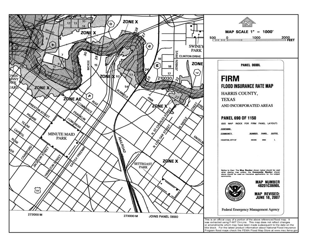
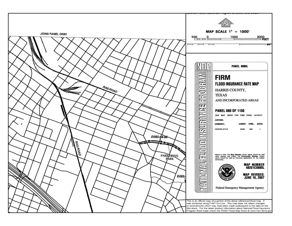
9 Drainage Report & Impact Analysis 5 2 DATA COLLECTION AND ELEVATION DATA 2.1 Data Collection The data collected and used for the drainage analysis include United States Geological Survey (USGS) topographic maps and t h e City of ouston GIMS information. As-built record drawings of the existing storm sewer systems were reviewed to determine the sizes, capacity, and approximate depth of the existing storm sewers. The floodplain maps in the vicinity of the project locations were obtained from the latest available Federal Emergency Management Agency (FEMA) Flood Insurance Rate Maps (FIRM) and are included in Appendix B. The maps indicate that the West Belt project locations are located outside the FEMA effective 100-year floodplain. 2.2 Elevation Data Elevation data used in this analysis includes topographic survey and as-built drawings (to approximate relative depths of existing storm sewers). In addition, contour data and overland flow paths from the City of ouston GIMS website was used.
10 Drainage Report & Impact Analysis 6 3 METODOLOGY 3.1 ydrology Peak flows were calculated using the rational method (Q=CIA). Rainfall intensity was calculated using the following equation from the City of ouston Design Manual. This equation is known as the rainfall intensity-duration-frequency (IDF) relationship. TxDOT s b, d, and e coefficients for arris County were used in rational method calculations. The equation for rainfall intensity is: where: I = average rainfall intensity t c = time of concentration = + The time of concentration equation from the City of ouston IDM was used to calculate the time of concentration of the project drainage areas to simplify drainage calculations. This equation is shown below: t c = 10A The underpass drainage areas are small enough to have actual times of concentration shorter than what is produced using the equation above. In order to provide a higher factor of safety against underpass flooding, the TxDOT minimum time of concentration of 10 minutes was used in calculating peak flows for underpass drainage areas.
11 Drainage Report & Impact Analysis ydraulics and Conceptual Pump Station Sizing ydraulic calculations for proposed storm sewer infrastructure associated with the West Belt Improvements will be provided in final design. ydraulic calculations will be performed based on the requirements of TxDOT and the City of ouston. Pumps stations are required to pump the surface runoff within the underpass areas to the proposed detention ponds. Runoff outside the underpass areas will be captured prior to reaching the underpass and routed directly to the detention ponds. Table 3-1 lists the peak flow rate (cfs) for the 100-year event required to be pumped. The flow rates were calculated using the rational method for the underpass drainage areas. Rational method calculations for the areas to be pumped are shown in Appendix B. Wet wells will be sized in final design based on Small Watershed method hydrographs of the pumped drainage areas shown in Appendix C. Table 3-1 Summary of Conceptual Pump Station Flow Rates (100 Year Event) Location Peak Flow Rate (cfs) Lyons 23.9 Runnels 32.2 Commerce and Navigation 55.8 York 49.9 Leeland and Cullen 81.9
12 Drainage Report & Impact Analysis Conceptual Detention Sizing Volumetric calculations based on a triangular Soil Conservation Service (SCS) hydrograph were used to calculate the required detention pond volumes. The required detention volume is calculated by subtracting out the volumes of storm water runoff that is conveyed through conduit or overland flow from the total runoff volume. The methodology is described in detail in the City of ouston s TP-101 as a Method 3 Analysis. owever, at the request of TxDOT, the 100-year analysis was performed for the 24-hour duration storm event instead of the 3-hour duration storm event recommended in TP-101. The 100-year, 24-hour duration rainfall depths were obtained from Section of the arris County Flood Control District Policy, Criteria, and Procedure Manual, December 2010 (CFCD PCPM). The depths for Region 2 (Buffalo Bayou Watershed) were used in the analysis. The TP-101 methodology is graphically illustrated in the figure below. Detention volume calculations are shown in Appendix B. Figure 3-1 Graphic Illustration of TP-101 Method 3
13 Drainage Report & Impact Analysis 9 4 CONCEPTUAL DRAINAGE DESIGN 4.1 Objective The grade separation of the roadway under the railroad tracks requires excavation in excess of twenty feet to allow vehicles to pass under the railway. This significant amount of excavation increases the risk of roadway flooding, possibly rendering the roadway inaccessible to drivers during major storm events. The following sections provide a drainage analysis and conceptual design of proposed drainage infrastructure required to protect the underpasses from flooding. 4.2 On-Site Detention Detention ponds are best management practices (BMP) for detaining storm water runoff during peak storm events, provide flood protection, and reduce the peak flows to the existing storm sewer systems. Detained storm water is then released over a longer period of time into the storm water system. Detention ponds are typically used to mitigate increases in storm runoff caused by development (i.e. increased impervious area). owever, the primary purpose of detention for the West Belt Improvements is to provide storage volume for areas where storm runoff can no longer utilize existing sheet flow paths due to the proposed underpasses. The detention ponds will allow the sheet flow runoff to be detained while releasing the flow into the existing storm sewer at a rate that the storm sewer system can accommodate. Section 4.3 provides a detailed description of the drainage analysis for each of the five grade separations in the West Belt Improvements. Detention calculations are provided in Appendix B.
14 Drainage Report & Impact Analysis Conceptual Drainage Plan The following approach was used in developing a conceptual drainage design for the proposed grade separations: Determine the drainage area for the proposed underpass limits and calculate the 100- year rational method peak flow. The peak flow from the underpass drainage area will be the required pump capacity for the 100-year storm event as discussed in Section 3.2. Delineate offsite drainage areas and evaluate overland sheet flow patterns to determine the following: 1) The proposed sheet flow corridors that will need to be provided. 2) The additional detention volume that needs to be provided for offsite drainage areas where existing sheet flow paths cannot be preserved. Determine the detention volume required for the proposed grade separations to detain storm runoff that is to be either of the following: 1) Pumped from the underpass drainage areas of the proposed grade separations. 2) Captured and detained prior to reaching the proposed underpasses (offsite drainage areas) where existing sheet flow paths cannot be preserved. Overland sheet flow patterns were analyzed for each of the five project locations. The existing sheet flow patterns will be preserved as much as possible. In cases where the proposed underpasses will impede the existing sheet flow paths, the detention basins have been sized to detain runoff from the overland flow drainage areas. The volume of the proposed basins is based on the 100-year, 24-hour storm event in accordance with directives from TxDOT.
15 Drainage Report & Impact Analysis 11 The following sections outline the conceptual drainage plans for each of the five grade separations in the West Belt Improvements. Table 4-2 below summarizes the detention requirements for each of the proposed grade separations. Table 4-1 Summary of West Belt Improvements Required Detention Volumes Grade Separation Location Required Detention Volume (acre-ft) Proposed Peak Outflow (cfs) Proposed Pond Area and Depth acre Lyons 2.0 (1) Runnels (2) Commerce/ Navigation York (2) Leeland/ Cullen (1) Detention for offsite drainage areas of the Lyons grade separation is included in plans for the proposed ardy Connector at Interstate 10. The detention required assumes detention for the proposed ardy Connector is constructed prior to the proposed grade separation at Lyons. The detention required if the ardy Connector has not yet been constructed is 12.5 acre-feet. (2) Peak Outflow includes consideration of other storm sewers conveying flow from overland drainage area. Existing storm sewer systems assumed to have 2-year capacity in accordance with City of ouston TP-101 guidelines. ft.
16 Drainage Report & Impact Analysis Lyons Grade Separation Exhibit 3.1 shows the conceptual drainage plan for the proposed grade separation at Lyons Avenue. The Lyons Avenue grade separation will have an underpass drainage area (Drainage Area L1) of 2.0 acres. Drainage Area L1 will be pumped and requires a design pump capacity of approximately 23.9 cfs based on the 100-year peak flow from this area. The Lyons Avenue grade separation will obstruct an existing overland flow path that runs north to south along West Street. The proposed ardy Connector will extend the ardy Toll Road from Interstate 610 to Interstate 10. The drainage plan for the ardy Connector includes detention for the Lyons grade separation offsite drainage areas. Right-of-way for the ardy Connector detention has been partially obtained by the arris County Toll Road Authority (CTRA). The ardy Connector detention basins are expected to be constructed prior to the Lyons grade separation. The Lyons grade separation will only require detention for the Lyons underpass drainage area that is to be pumped. The detention required for the Lyons grade separation is approximately 2.0 acre-feet (See Appendix D for Lyons detention pond calculations). This assumes the detention for the ardy Connector is constructed prior to the Lyons grade separation (See Appendix E for the ardy Connector drainage plan at Lyons). Additional coordination with CTRA is recommended. If the ardy Connector detention is not constructed, the detention required for the Lyons grade separation is approximately 12.5 acre-feet (See Appendix B for calculations). The additional detention would be required for the offsite drainage areas L2 and L3 (See Exhibit 3.1) where overland flow paths would be obstructed.
17 Drainage Report & Impact Analysis Runnels Grade Separation Exhibit 3.2 shows the conceptual drainage plan for the Runnels Street proposed grade separation. The Runnels Street grade separation has an underpass drainage area (drainage area R1) of 2.7 acres. Drainage area R1 will be pumped and requires a design pump capacity of approximately 32.2 cfs based on the 100-year peak flow from this area. The Runnels Street grade separation will obstruct an existing sheet flow path that runs north along the existing ouston Belt & Terminal Railroad tracks to Buffalo Bayou. A proposed detention pond will be located south of Runnels and east of the ouston Belt & Terminal Railroad tracks. The detention pond will detain storm water that is pumped from the underpass area in addition to the runoff volume from contributing offsite drainage area R2 (See Exhibit 3.2). The proposed detention pond will outfall into an existing 42-inch storm sewer (City of ouston Plan #16998) that is the main trunk line for City of ouston CDP drainage area W0660. The existing 42-inch storm sewer is approximately thirty feet deep (from natural ground to top-of-pipe) according to as-built drawings. The existing storm sewer will have approximately four feet of cover at Runnels after the proposed grade separation is constructed. The depth of the existing storm sewer will need to be verified prior to final design. The conduit flow component in the TP-101 detention evaluation was determined based on the 2-year flow from the portion of the overland flow drainage area that is within City of ouston CDP drainage area W0660 (allocated W0660 area). The total allocated W0660 area is 10.4 acres with a 2-year flow of 30.8 cfs. The detention basin volume required at Runnels Street is approximately 9.3 acre-feet. See detention pond calculations in Appendix B.
18 Drainage Report & Impact Analysis Commerce / Navigation Grade Separation Exhibit 3.3 shows the conceptual drainage plan for the Commerce Street and Navigation Boulevard proposed grade separation. The Commerce Street and Navigation Boulevard grade separation has an underpass drainage area (drainage area C1) of 4.7 acres. Drainage area C1 will be pumped and requires a design pump capacity of approximately 55.8 cfs based on the 100-year peak flow from this area. The proposed detention pond will be located north of Navigation Boulevard and west of the ouston Belt & Terminal Railroad tracks. The detention pond will detain storm water that is pumped from the underpass area in addition to the runoff volume from contributing offsite drainage area C2. The overland flow path for offsite drainage area C2 (See Exhibit 3.3) will be obstructed by the proposed Runnels underpass (see Section 4.3.2). The proposed detention basin will outfall into the same existing 42-inch storm sewer as the Runnels detention pond (City of ouston Plan #16998). The detention pond outfall rate was determined based on the 2-year flow from the portion of the detention pond drainage area that is within City of ouston CDP drainage area W0660 (allocated W0660 area). The total allocated W0660 area is 1.5 acres with a 2-year flow of 4.9 cfs. Proposed sheet flow corridors will be provided in the final design to preserve the natural direction of flow from overland drainage areas C3 and C4 draining away from the grade separation limits. The detention pond volume required at Commerce / Navigation is approximately 10.0 acre-feet. See detention pond calculations in Appendix B.
19 Drainage Report & Impact Analysis York Grade Separation Exhibit 3.4 shows the conceptual drainage plan for the York Street proposed grade separation. The York Street grade separation has an underpass drainage area (drainage area Y1) of 4.2 acres. Drainage area Y1 will be pumped and requires a design pump capacity of approximately 49.9 cfs based on the 100-year peak flow from this area. The York grade separation will obstruct an existing sheet flow path north of Rusk Street along the existing railroad corridor. A proposed detention pond will be located west of Sampson Street on property currently owned by the Union Pacific Railroad. The detention pond will detain storm water that is pumped from the underpass area in addition to the runoff volume from contributing offsite drainage area Y2 (See Exhibit 3.4). The proposed detention pond will outfall into existing storm sewer along Sampson Street (City of ouston Plan #4196). An existing 84-inch storm sewer trunk line for CDP drainage area D0038 (City of ouston Plan #9495) crosses York Street at Lamar Street. The 84-inch storm sewer has been located in survey and appears to have sufficient depth to not require relocation for the proposed underpass at York Street. Overland drainage area Y2 is served by several existing storm sewer systems that appear to be interconnected based on City of ouston GIMS data. For analysis purposes, the 2- year flow from offsite drainage area Y2 of 85.2 cfs was assumed to be conveyed in the existing storm sewer systems by conduit flow. The detention pond volume required at York is approximately 7.0 acre-feet. See detention pond calculations in Appendix B.
20 Drainage Report & Impact Analysis Leeland and Cullen Grade Separation Exhibit 3.5 shows the conceptual drainage plan for the Leeland Street and Cullen Boulevard proposed grade separation. The Leeland Street and Cullen Boulevard grade separation has an underpass drainage area (drainage area LC1) of 6.9 acres. Drainage area LC1 will be pumped and requires a design pump capacity of approximately 81.9 cfs based on the 100-year peak flow from this area. The existing 84-inch storm sewer trunk line along Leeland Street (City of ouston Plan #4227 and 4071) does not have sufficient depth for the proposed depressed roadway section and will need to be relocated. At the request of TxDOT, an option of upsizing the storm sewer trunk line (in lieu of providing detention) was evaluated. A conceptual hydraulic analysis (See Appendix F) was performed to determine the approximate amount of storm sewer upsizing that would be required. The analysis assumed the existing system was at capacity in the existing condition. Additional flow was added for the proposed condition to account for the 100-year flow that would be pumped from the grade separation limits and offsite drainage areas where overland flow paths were obstructed. The analysis showed that approximately 2,100 linear feet of storm sewer would need to be upsized to a 10 x 7 box culvert to accommodate the additional flow. The cost of the proposed storm sewer alone would be approximately 1.3 million dollars (based on current TxDOT unit price of $625 per linear foot of 10 x 7 box culvert). This cost does not include the additional utility relocations and roadway reconstruction that would be required for the upsizing the storm sewer downstream of the current project limits. The right-of-way needed for the detention option will already need to be acquired due to access constraints caused by the construction of the Leeland Street and Cullen Boulevard underpasses. Therefore, the detention option was considered more economically feasible than the upsizing option. The proposed detention pond will be located south of Leeland Street and west of the ouston Belt & Terminal Railroad tracks. The detention pond will detain storm water that is pumped from the underpass area in addition to the runoff volume from contributing overland drainage area LC2 (See Exhibit 3.5). The proposed detention pond will outfall into the existing 84-inch storm sewer along Leeland Street (City of ouston Plan # 4227 and 4071).
21 Drainage Report & Impact Analysis 17 The detention pond release rate of 13.9 cfs was determined based on the 2-year flow from the portion of the detention pond drainage area that is within City of ouston CDP drainage area D0038 (allocated D0038 area). Proposed sheet flow corridors will be provided in the final design to preserve the natural direction of overland flow from overland drainage area LC3 (See Exhibit 3.5) along ussion Street and Clay Street. The detention pond volume required at Leeland Street and Cullen Boulevard is approximately 15.5 acre-feet. See calculations in Appendix B.
22 Drainage Report & Impact Analysis 18 5 SUMMARY AND CONCLUSIONS The purpose of this report is to document the drainage analysis for the five proposed grade separation projects associated with the proposed West Belt Improvements. In addition, this report provides a the conceptual drainage analysis and conceptual drainage design for where the B&T railroad crosses Lyons Avenue, Runnels Street, Commerce Street and Navigation Boulevard, York Street, and Leeland Street and Cullen Boulevard. The West Belt Improvements will result in minimal changes in impervious area from the existing conditions. The conceptual detention basins are designed to outfall to the existing City of ouston storm sewers based on the existing system capacity. The conceptual detentions can provide storage volume for the following: a. Overland drainage areas where the overland flow path is obstructed by the proposed grade separations. b. Storm water that is pumped from underpass areas of the proposed grade separations. 2. Section 4.3 of this report outlines the conceptual drainage plans for the West Belt Improvements. The conceptual drainage plans for the West Belt Improvements are shown in Exhibit 3. Detention volume and pump sizing calculations are shown in Appendix B (Appendix D for the Lyons Grade Separation). The required pump station capacities for the grade separations are summarized in Table 4-1 and the required detention volumes are shown in Table 4-2.

23 EXIBIT 1 Location Map Lyons Avenue N Runnels Street Commerce Street & Navigation Boulevard York Street Leeland Street & Cullen Boulevard


24 EXIBIT 2 - City of ouston Comprehensive Drainage Plan Drainage Areas W0486 Lyons Avenue N W0660 Runnels Street W0635 W0703 W0705 W0704 Commerce Street & Navigation Boulevard W0706 York Street D0038 Leeland Street & Cullen Boulevard D7005
25 EXIBIT 3 Preliminary Drainage Plan EXIBIT 3.1 Lyons Avenue Grade Separation Preliminary Drainage Plan EXIBIT 3.2 Runnels Street Grade Separation Preliminary Drainage Plan EXIBIT 3.3 Commerce / Navigation Grade Separation Preliminary Drainage Plan EXIBIT 3.4 York Street Preliminary Drainage Plan EXIBIT 3.5 Leeland / Cullen Preliminary Drainage Plan
26 CO 18 Pl inch an # Outfall C1 4.9C cfs an al t ga vi a N n io # Legend Interstates US ighways lpi ne tr e s CDP Drainage Areas Proposed Pipe Co lby Layer CO 24 inch Pl an # Storm Node Detention Ponds Offsite Drainage Area Pumped Drainage Area les Existing Storm Sewer Ch ar W0660 Allocated Area u tc h ins Sa int Sheet Flow Direction Detention Outfall Proposed Sheet Co Flow Corridor mm er ce Drainage L1 Area I.D. C4 C3 W op Ba s tr Oa k Proposed Pump Station es s Liv e Co ng r Edge of Pavement C1 Ba st Sa in te W0704 Mc A ro p ma nu el Ch ar CO 24 Pl inch an # CO 21 Pla inch n# CO 3 0 -i Pl nc an h # CO 2 4 -i Pl nc an h # Pr es to n CO 2 Runnels Detention Basin 4 -i Pl nc an h - See Exhibit 3.2 Railroad CO 18 Pl inch an # a mi lto n W0635 Acres 100-Year Flow (cfs) (blue background = pumped area) Source: Esri, DigitalGlobe, GeoEye, i-cubed, Earthstar Geographics, CNES/Airbus DS, USDA, USGS, AEX, Getmapping, Aerogrid, IGN, IGP, swisstopo, and the GIS User Community Commerce / Navigation Conceptual Drainage Plan (Detention Using 100-year, 24-hour Storm Runoff Depths) Do wl ing as CO 48 Pla inch n# Te x C2 6.1 W0660 W0661 Ramp t CO 4 8 -i Pl nc an h # CO 24 Pl inch an # CO 2 4 -i Pla nc n# h Ja ck so n Ch en ev er O 24 Commerce/Navigation CDetention Basin Pl -inc an h Detention Required: 10.0 Acre-ft # 41 Fr 10 an (Routes Flow from Drainage Areas 8 kli n and C2) W0703 C1 Ru nn els CO 4 2 -i Pl nc an h # W0660 Allocated Drainage Area (yellow highlight): 1.5 acres 2-year peak flow: 4.9 cfs City of ouston, arris County, Texas August in = 300 ft Exhibit 3.3

27 Y1 Outfall Y2 4.2 W CO 24 Pla -inch n# CO 36 -in ch Plan #4068 CO 30 Pl inch an # Ev er Railroad CDP Drainage Areas Proposed Pipe Existing Storm Sewer Storm Node Edge of Pavement Proposed Detention Offsite Draiange Area CO 21 Pl inch an # Pumped Drainage Area Sheet FlowCaDirection pito l Mi lby Detention Rus Outfall k Wal ker Proposed Sheet Flow Corridor L1 gu s ti ne 2.0 Au 18.8 Sa int Sa int Jo se ph Proposed Pump Station Drainage Area I.D. Acres 100-Year Flow (cfs) York Street Conceptual Drainage Plan (Detention Using 100-year, 24-hour Storm Runoff Depths) City of ouston, arris County, Texas August in = 300 ft Cu lle n (blue background = pumped area) Source: Esri, DigitalGlobe, GeoEye, i-cubed, Earthstar Geographics, CNES/Airbus DS, USDA, USGS, AEX, Getmapping, Aerogrid, IGN, IGP, swisstopo, and the GIS User Community Lam ar r US ighways CO 30 Pl inch an # CO 2 4 -i Pl nc an h # ney Wi lme Interstates CO 18 Pl inch an # McK in Legend 8 ch 06 -in n #4 18 la P O C 8 CO 84 Pl inch an # Pr es to n CO 18 Pl inch an # CO 3 0 -i Pl nc an h # Sa mp so n 5 CO 3 6 -i Pl nc an h # Da lla s Scott Po lk CO 1 8 -i Pl nc an h # CO 30 Pla -inc n# h CO 2 4 -i Pl nc an h # D D0038 CO 18 Pla inch n# CO 18 Pl inch an # Ru sk to n u tc h es on k CO 1 8 -i Pl nc an h # CO 18 Pla inch n# ts CO 72 Pl inch an # Outfall Y1 Ro be r r CO 36 Pla inch n# Lo t 6 CO 18 Pla -inc n# h La ma as 0 York Street Detention Basin Detention Required: 7.0 Acre-ft (Routes Flow from Drainage Areas Y1 and Y2) CO 2 4 -i Pl nc an h # CO 24 Pl inch an # CO 36 Pl inch an # W0706 ing CO 18 -in P c lan h #25 78 Te x CO 24 Pl inch an # year flow from overland drainage area Y2 assumed tocbe ap conveyed in existing ito storm sewer system l in accordance with TP-101 guidelines: 85.2 cfs g Yo r ts Ro be r 25.4 Pa rk En nis Y2 a rri sb ur CO 60 Pl inch an # sk u tc h es on W0705 Ru Exhibit 3.4
28 APPENDIX A FEMA Flood Maps
29
30
31 APPENDIX B Detention and Pump Sizing Calculations
 (ac) -")
32 Gulf Coast Rail District West Belt Improvements Appendix B - Detention and Pump Sizing Calculations Commerce Street and Navigation Boulevard Intersection Runoff Calculations for Individual Drainage Areas Required Pump Rates Lyons Avenue Detention Basin Outlet Locations Drainage Area ID Area Runoff Cofficient 'C' Tc Intensity Peak Flow 2-Year 100-Year 2-Year 100-Year Pumped Area (Yes/No) (ac) - (min) (in/hr) (in/hr) (cfs) (cfs) (cfs) C Yes 55.8 Pump Capacity Required Outlet # C1 Description Commerce/Navigation Detention Outfall into Exist 42" RCP (CO Plan # 16998) C No None C No None C No None Allocated W0660 Area No None Detention Basin Description Runoff Detention Volume TP-101 Method 3 Check Intensity Peak Flow Detention Basin Description Contributing Drainage Areas Area Weighted Runoff Cofficient 'C' Tc 2-Year 100-Year 2-Year 100-Year Conduit Flow Component Q c (Q T ) Basis for Determination of Conduit Flow Component Proposed Detention Storage Volume (V s avail) Percent Impervious Runoff Depth Runoff Volume (V T ) Maximum Allowable Overland Flow (Q Oallow ) (ac) - (min) (in/hr) (in/hr) (cfs) (cfs) Storm Outlet # (cfs) (ac-ft) % (in) (ac-ft) (cfs) (cfs) Required Overland Flow (Q oreqd ) CECK Is Qoallow >= Qoreqd? Yes = Acceptable No = Unacceptable Commerce/Na Proposed basin north of Commerce Street and vigation west of West Belt Line C1, C C year flow from Allocated W0660 Area % Yes n.a. Sub-Area C3 (Provide Sheetflow Corridor) C n.a % No n.a. Sub-Area C4 (Provide Sheetflow Corridor) C n.a % No If "Yes", design for storm sewer segment meets City of ouston Requirements. If "No", design for storm sewer segment does not meet City of ouston requirements and adjustment in storm sewer size or additional analysis are needed. Rainfall Intensity Rainfall Depth (in) 2-Year 24-r Duration b 68 0% d % e % Year b 91 d 7.9 Detention Volume Required (based on allowable detention basin outfall rate to storm sewer). Sized for100-year, 3-hour storm event. Percent Impervious = (C composite - 0.2)/0.6 CFCD Direct Runoff Depths for 24-hour, 1% Probability Rainfall Event (100-year) V T = Runoff Depth x ACUM Allowable overland flow release rate out of overland drainage area. Qoreqd = Q T - QC,Basin Out - ((VSavail x QT 2 )/(V T (QT - QC, Basin Out)) Vsavail and V T) are cumulative values. e Inlet Tc as Determined by engineer. 10A^ Q = CIA Intensity = b/(tc+d)^e (TxDOT Values for arris County) Detention basin storm outlet identifier and basin outfall rate for determining detention volume. Refer to Exhibit 3.3. Technical basis for determining the allowable outfall rate from the detention basin. See Below for Detention Calculation pw:\\p gcrd West Belt PE\EA\30.0-Con Design\30.01-Gen Info\DataIn\Gulf Coast Fr Rail\ WestBelt NTB Files\GCRD_drawings\DGN\Bas\Stormwat\yd PhaII\Rep\Upd Rep\West Belt Detention and Pump Sizing.xlsm Page 3 of 5
33 Gulf Coast Rail District West Belt Improvements Appendix B - Detention and Pump Sizing Calculations York Street Intersection Runoff Calculations for Individual Drainage Areas Required Pump Rates Lyons Avenue Detention Basin Outlet Locations Drainage Area ID Runoff Cofficient 'C' Tc Intensity Peak Flow Pumped Area (Yes/No) Area 2-Year 100-Year 2-Year 100-Year (ac) - (min) (in/hr) (in/hr) (cfs) (cfs) (cfs) Pump Capacity Required Outlet # Y1 & Y2 Description Existing 36" Storm Sewer on Sampson CO Plan # 4196 Y Yes 49.9 Y No None Detention Basin Description Runoff Detention Volume TP-101 Method 3 Check Intensity Peak Flow Detention Basin Description Contributing Drainage Areas Area Weighted Runoff Cofficient 'C' Tc 2-Year 100-Year 2-Year 100-Year (Q T ) Conduit Flow Component Q c Basis for Determination of Conduit Flow Component Proposed Detention Storage Volume (V s avail) Percent Impervious Runoff Depth Runoff Volume (V T ) Maximum Allowable Overland Flow (Q Oallow ) (ac) - (min) (in/hr) (in/hr) (cfs) (cfs) Storm Outlet # (cfs) (ac-ft) % (in) (ac-ft) (cfs) (cfs) Required Overland Flow (Q oreqd ) CECK Is Qoallow >= Qoreqd? Yes = Acceptable No = Unacceptable Proposed basin west of York Street and south of the West Belt Line 2-Year flow from contributing drainage area (contributing drainage area is overland sheet flow drainage area, storm sewer infrastructure exists in the overland drainage area and it is assumed to have capacity for 2-year flow). This is not the actual detention basin outfall rate. York Basin Y1, Y Y % Yes 2-Year 24-r Duration b 68 0% d % e % Year b 91 d 7.9 e Inlet Tc as Determined by engineer. 10A^ Q = CIA Intensity = b/(tc+d)^e (TxDOT Values for arris County) Detention basin storm outlet identifier and basin outfall rate for determining detention volume. Refer to Exhibit 3.4 Technical basis for determining the allowable outfall rate from the detention basin. If "Yes", design for storm sewer segment meets City of ouston Requirements. If "No", design for storm sewer segment does not meet City of ouston requirements and adjustment in storm sewer size or additional analysis are needed. Rainfall Intensity Rainfall Depth (in) Detention Volume Required (based on allowable detention basin outfall rate to storm sewer). Sized for100-year, 3-hour storm event. Percent Impervious = (C composite - 0.2)/0.6 CFCD Direct Runoff Depths for 24-hour, 1% Probability Rainfall Event (100-year) V T = Runoff Depth x ACUM Allowable overland flow release rate out of overland drainage area. Qoreqd = Q T - QC,Basin Out - ((VSavail x QT 2 )/(V T (QT - QC, Basin Out)) Vsavail and V T) are cumulative values. See Below for Detention Calculation pw:\\p gcrd West Belt PE\EA\30.0-Con Design\30.01-Gen Info\DataIn\Gulf Coast Fr Rail\ WestBelt NTB Files\GCRD_drawings\DGN\Bas\Stormwat\yd PhaII\Rep\Upd Rep\West Belt Detention and Pump Sizing.xlsm Page 4 of 5
34 APPENDIX C Small Watershed ydrographs of Pumped Areas
35 Gulf Coast Rail District West Belt Improvements Appendix C - Small Watershed ydrographs of Pumped Areas Watershed Name: Commerce/Navigation Area (acres): 4.7 Rainfall Excess (inches): 13.2 % Impervious: 100% Peak Discharge (cfs): 55.8 Time to Peak (min): 48 Recommended Time Interval (min): 5 Calculation Time Interval (min): 5 Flow (cfs) Commerce / Navigation, 100-Year 24-hr Storm ydrograph Developed ydrograph Time (Minutes) Time (min) Dev. Discharge Time (min) Dev. Discharge pw:\\p gcrd West Belt PE\EA\30.0-Con Design\30.01-Gen Info\DataIn\Gulf Coast Fr Rail\ WestBelt NTB Files\GCRD_drawings\DGN\Bas\Stormwat\yd PhaII\Rep\Upd Rep\100-year ydrographs for pumped areas.xlsm Page 3 of 5
36 Gulf Coast Rail District West Belt Improvements Appendix C - Small Watershed ydrographs of Pumped Areas Watershed Name: York Area (acres): 4.2 Rainfall Excess (inches): 13.2 % Impervious: 100% Peak Discharge (cfs): 49.9 Time to Peak (min): 48 Recommended Time Interval (min): 5 Calculation Time Interval (min): 5 Flow (cfs) York, 100-Year 24-hr Storm ydrograph Developed ydrograph Time (Minutes) Time (min) Dev. Discharge Time (min) Dev. Discharge pw:\\p gcrd West Belt PE\EA\30.0-Con Design\30.01-Gen Info\DataIn\Gulf Coast Fr Rail\ WestBelt NTB Files\GCRD_drawings\DGN\Bas\Stormwat\yd PhaII\Rep\Upd Rep\100-year ydrographs for pumped areas.xlsm Page 4 of 5
CHECKLIST FOR PHASE II DRAINAGE REPORT
 I. COVER SHEET CHECKLIST FOR PHASE II DRAINAGE REPORT A. Name of Project B. Address C. Owner D. Developer E. Engineer F. Submittal date and revision dates as applicable II. GENERAL LOCATION AND DESCRIPTION
STAFFORD TRACT NORTH OF US90A 1.0 INTRODUCTION 1.1 OBJECTIVE
 1.0 INTRODUCTION 1.1 OBJECTIVE This report, prepared for submittal to TxDOT, analyzes existing and proposed detention facilities draining into the TxDOT US90A storm sewer system. The results of the detailed
October 7, City of Thornton 9500 Civic Center Drive Thornton, CO (303) RE: Maverik Thornton, CO - Drainage Report
 RE: Maverik Thornton, CO - Drainage Report") October 7, 2016 City of Thornton 9500 Civic Center Drive Thornton, CO 80229 (303) 538-7295 RE: Maverik Thornton, CO - Drainage Report As per your request, we are submitting to you the drainage report and
October 7, 2016 City of Thornton 9500 Civic Center Drive Thornton, CO 80229 (303) 538-7295 RE: Maverik Thornton, CO - Drainage Report As per your request, we are submitting to you the drainage report and
STORMWATER REPORT FOR WALMART SUPERCENTER STORE # SIOUX FALLS, LINCOLN COUNTY, SOUTH DAKOTA BFA PROJECT NO
 STORMWATER REPORT FOR WALMART SUPERCENTER STORE # 2443-00 SIOUX FALLS, LINCOLN COUNTY, SOUTH DAKOTA BFA PROJECT NO. 3286 March 1, 2012 I hereby certify that this engineering document was prepared by me
PCE PRELIMINARY DRAINAGE ANALYSIS REPORT FOR WESTWOOD MIXED USE NEIGHBORHOOD PROJECT 772 NORTH FOREST ROAD TOWN OF AMHERST, ERIE COUNTY, NEW YORK
 PCE PRELIMINARY DRAINAGE ANALYSIS REPORT FOR WESTWOOD MIXED USE NEIGHBORHOOD PROJECT 772 NORTH FOREST ROAD TOWN OF AMHERST, ERIE COUNTY, NEW YORK MAY 19, 2014 Prepared By: Timothy M. Lavocat, P.E., CFM
PHASE III DRAINAGE REPORT
 PHASE III DRAINAGE REPORT FOR Eastlake Assisted Living & Memory Care April 20, 2016 June 3, 2016 August 5, 2016 Prepared for: 3301 E 120 th Ave, LLC. 8200 E. Maplewood Ave., Suite 150 Greenwood Village
TENNESSEE GAS PIPELINE COMPANY, L.L.C.
 TENNESSEE GAS PIPELINE COMPANY, L.L.C. HYDROLOGIC AND HYDRAULIC CALCULATIONS FOR ACCESS ROADS ALONG THE CONNECTICUT PIPELINE EXPANSION PROJECT CONNECTICUT LOOP Submitted by: Tennessee Gas Pipeline Company,
HEALTH SCIENCES BUILDING REDEVELOPMENT PROJECT
 INTRODUCTION In recent years, the University of Cincinnati (University) has demonstrated a commitment to identifying and implementing sustainable goals and objectives throughout University s Uptown Campuses.
APPENDIX B. Hydrologic and Hydraulic Analysis
 APPENDIX B Hydrologic and Hydraulic Analysis HYDROLOGIC AND HYDRAULIC ANALYSIS PETERSBURG ROAD IMPROVEMENTS DOT&PF Project No. 67879 Prepared for: State of Alaska Department of Transportation and Public
BRISBANE BAYLANDS INFRASTRUCTURE PLAN FEBRUARY 2011 APPENDIX O DRAFT
 BRISBANE BAYLANDS INFRASTRUCTURE PLAN FEBRUARY 2011 APPENDIX O DRAFT PRELIMINARY STORM DRAIN CALCULATIONS ASSOCIATED WITH BRISBANE BAYLANDS REDEVELOPMENT BRISBANE, CALIFORNIA Prepared by BKF Engineers
City of Waco Stormwater Management Regulations
 1.0 Applicability: City of Waco Stormwater Management Regulations These regulations apply to all development within the limits of the City of Waco as well as to any subdivisions within the extra territorial
Figure 1 Cypress Street Study Area Location Map
 July 20, 2016 TO: FROM: Jim Massarelli Director of Engineering Jeff Julkowski, PE Michael Burke, PE SUBJECT: Cypress Street Study Area Stormwater Analysis (CBBEL Project No. 16-0058) At the request of
Chapter 4 - Preparation of Stormwater Site Plans
 Chapter 4 - Preparation of Stormwater Site Plans The Stormwater Site Plan is the comprehensive report containing all of the technical information and analysis necessary for the City to evaluate a proposed
1. Project Description
 To: By: Checked By: Jimmy Vilce, E.I. (FOT istrict 1 Project Manager) Jennifer Nunn, P.E. (The Balmoral Group) Lori Stanfill, P.E. (The Balmoral Group) Memorandum ate: July 10, 2018 Subject: In May of
Table of Contents G.1.a Water Resources - Surface Water - Drainage
 Table of Contents G.1.a Water Resources - Surface Water - Drainage 1. INTRODUCTION... 1335 2. ENVIRONMENTAL SETTING... 1335 a. Regional Hydrology... 1335 b. Local Hydrology... 1337 c. On-site Hydrology...
Village of Forest Park. July 27, Sewer Separation Evaluation
 Village of Forest Park July 27, 2015 Sewer Separation Evaluation Presentation Overview Study Background Historic Nature of Forest Park Drainage Scale of Flooding Problem Forest Park Sewer System Background
City of Elmhurst. Comprehensive Flood Plan. City of Elmhurst. City Council Meeting September 15, 2014
 City of Elmhurst City of Elmhurst Comprehensive Flood Plan City Council Meeting September 15, 2014 City of Elmhurst Presentation Overview Study Background Study Methodology Analysis of Three Additional
MASTER DEVELOPMENT DRAINAGE PLAN FOR MONUMENT HEIGHTS
 MASTER DEVELOPMENT DRAINAGE PLAN FOR MONUMENT HEIGHTS DRAINAGE REPORT STATEMENT ENGINEER'S STATEMENT: The attached drainage plan and report were prepared under my direction and supervision and are correct
When planning stormwater management facilities, the following principles shall be applied where possible.
 2.0 Principles When planning stormwater management facilities, the following principles shall be applied where possible. 2.0.1 Drainage is a regional phenomenon that does not respect the boundaries between
South Bismarck Watershed Model Update and Stormwater Improvement Project
 Preliminary Engineering Report Bismarck Tribune South Bismarck Watershed Model Update and Stormwater Improvement Project City of Bismarck, ND January 2017 14.105.0046 1.0 Executive Summary The focus of
NAPA COUNTY PUBLIC WORKS Standards & Specifications
 Roadway Design & Construction Manual (Table of Contents) 1. Chapter 1: General Provisions 1.1 Short Title 1.2 Jurisdiction 1.3 Purpose and Effect 1.4 Enactment Authority 1.5 Amendment and Revisions 1.6
Blake C. Kronkosky, PE, Ph.D.
 Blake C. Kronkosky, PE, Ph.D. Blake.Kronkosky@statetecheng.com, CELL (512) 663-1954 Education Ph.D., Civil Engineering, Texas Tech University, May 2018: An Engineer's Guide for Estimating 1-Day, 100-Year
City of Elmhurst. City of Elmhurst. Storm Sewer System Workshop November 22, 2010
 City of Elmhurst City of Elmhurst Storm Sewer System Workshop November 22, 2010 1 City of Elmhurst Watershed divide (green dashed line) through Elmhurst Area east of divide drains to Addison Creek Area
A. Regional Detention Requirements
 I. GENERAL DESIGN GUIDELINES A. Full-spectrum detention is provided for all new development, redevelopment or expansion of a site to provide for water quality and flood control detention. B. Detention
DRAINAGE CALCULATIONS
 DRAINAGE CALCULATIONS For the Carroll Single Family Residence At Santa Clara County Saratoga, California APN: 517-26-010 December 18, 2015 Prepared For: John and Peggy Carroll Prepared By: RI Engineering,
Lincoln 270. City of Lincoln. Stormwater Management Plan. April 2, 2013
 Lincoln 270 City of Lincoln Stormwater Management Plan April 2, 2013 # 2005.48 Prepared By: Civil Engineering Solutions, Inc. 590 E Street Lincoln, Ca 95648 (916) 645 5700 1.0 Background: The project site
PRELIMINARY DRAINAGE REPORT LATHAM 200 MMSCFD GAS PROCESSING PLANT
 PRELIMINARY DRAINAGE REPORT LATHAM 200 MMSCFD GAS PROCESSING PLANT LOTS B, RECORDED EXEMPTION 1211-2-1, RECX13-0096 LOCATED IN THE NORTH 1/2 OF SECTION 2, TOWNSHIP 3 NORTH, RANGE 66 WEST, 6 TH PRINCIPAL
ENVISIONING THE POSSIBILITIES OF A DIGITAL CITY: A CASE STUDY OF RAIN GARDENS AS FLOOD CONTROL IN AUSTIN, TEXAS CE 394K FALL 2011 PROF.
 ENVISIONING THE POSSIBILITIES OF A DIGITAL CITY: A CASE STUDY OF RAIN GARDENS AS FLOOD CONTROL IN AUSTIN, TEXAS BY KIERSTEN TYSSELAND DUBE CE 394K FALL 2011 PROF. MAIDMENT INTRODUCTION With the advent
November 2, 2015 at 5:15pm City Council Chambers, 3rd Floor, City Hall, 1737 Main Street Columbia, South Carolina 29201
 Subject Property: PLANNING COMMISSION SITE/SUBDIVISION PLAN CASE SUMMARY 10.21 ACRES, WESTSIDE OF CLIF KINDER BOULEVARD COTTAGES AT BURNSIDE FARM BURNSIDE FARMS ASSOCIATES, LLC November 2, 2015 at 5:15pm
4. CONCEPT PLAN DEVELOPMENT
 4. CONCEPT PLAN DEVELOPMENT Concept Plan Step 1: Identify Site Constraints and Opportunities Review the existing site to identify constraints and opportunities for GI Practices to meet the RRv. Constraints
Appendix K. Stormwater Management Plan
 Regional Municipality of Halton - Steeles Avenue (Regional Road 8) Class EA - Industrial Drive to Regional Road 25/Martin Street Appendix K Stormwater Management Plan PR226401.001 Rev. 2 PR.DOT, 00/01
I-494 Rehabilitation Project SP (I-394 to Fish Lake Interchange) June 2014 Section 4(f) De Minimis Determination
 June 2014 Section 4(f) De Minimis Determination") I-494 Rehabilitation Project SP 2785-330 (I-394 to Fish Lake Interchange) June 2014 Section 4(f) De Minimis Determination State Project Number 2785-330 Federal Project No. NHPP-I494 (002) Trunk Highway:
I-494 Rehabilitation Project SP 2785-330 (I-394 to Fish Lake Interchange) June 2014 Section 4(f) De Minimis Determination State Project Number 2785-330 Federal Project No. NHPP-I494 (002) Trunk Highway:
PLANNING AND NATURAL RESOURCES COMMITTEE. Public Access Conceptual Design Alternatives for the Red Barn Area of La Honda Creek Open Space Preserve
 PLANNING AND NATURAL RESOURCES COMMITTEE R-17-56 May 9, 2017 AGENDA ITEM AGENDA ITEM 2 Public Access Conceptual Design Alternatives for the Red Barn Area of La Honda Creek Open Space Preserve GENERAL MANAGER
Draft Rhode Island Stormwater Design and Installation Standards Manual
 Draft Rhode Island Stormwater Design and Installation Standards Manual Summary The May 2009 Public Review Draft version of the RI Stormwater Design and Installation Standards Manual consists of approximately
Hydrologic Assessment of using Low Impact Development to Mitigate the Impacts of Climate Change. Chris Jensen, AScT Master of Science Thesis
 Hydrologic Assessment of using Low Impact Development to Mitigate the Impacts of Climate Change Chris Jensen, AScT Master of Science Thesis Bowker Creek Initiative April 12, 2012 Outline 1. Future Impacts
City of Richmond. Engineering Design Specifications
 City of Richmond Design Specifications June 2008 CITY OF RICHMOND ENGINEERING DESIGN SPECIFICATIONS JUNE 2008 THIS DOCUMENT DETAILS THE MINIMUM STANDARDS TO BE USED FOR THE DESIGN OF ENGINEERING PROJECTS
 PSLS Surveyors' Conference Workshop Information Form Workshop Number: (leave blank if unknown) Hours: Workshop Title: Workshop Description: Suggested Speaker(s), affiliation/contact information 1. 2. 3.
WASHINGTON COUNTY OREGON
 WASHINGTON COUNTY OREGON LONG RANGE PLANNING DIVISION North Bethany Subarea Stream Corridors: Existing Regulations In Oregon, there is a distinct difference between the land use rules that apply in rural
MANUAL OF DESIGN, INSTALLATION, AND MAINTENANCE REQUIREMENTS FOR STORMWATER MANAGEMENT PLANS
 MANUAL OF DESIGN, INSTALLATION, AND MAINTENANCE REQUIREMENTS FOR STORMWATER MANAGEMENT PLANS May 2007 SECTION 1 Responsibility of Applicant TABLE OF CONTENTS A. Stormwater Management Plan Required Information
Information for File # MMJ; Methodist Hospital Flood Storage Mitigation and Wetland Enhancement Project
 Information for File # 2016-01223-MMJ; Methodist Hospital Flood Storage Mitigation and Wetland Enhancement Project Applicant: Park Nicollet, Attn: Robert Riesselman Corps Contact: Melissa Jenny Address:
Appendix 6-A. Site Plan Preparation and Submission as Part of the Land Development Process
 Appendix 6-A Site Plan Preparation and Submission as Part of the Land Development Process Table of Contents Appendix Section Headings 6-A.1.0 INTRODUCTION 6-A-2 6-A.2.0 THE STORMWATER MANAGEMENT PLAN 6-A-6
CITY OF VALPARAISO STORMWATER MASTER PLAN
 CITY OF VALPARAISO STORMWATER MASTER PLAN APPROVED BY THE VALPARAISO CITY UTILITIES BOARD OCTOBER, 2016 Prepared by the City of Valparaiso Engineering Department PLAN SUMMARY Major flash flooding in August
6.1. INTRODUCTION AND SUMMARY OF FINDINGS
 Chapter 6: Stormwater Management 6.1. INTRODUCTION AND SUMMARY OF FINDINGS A Stormwater Pollution Prevention Plan (SWPPP) has been prepared for the Proposed Project in accordance with the requirements
continues in the watershed, additional flood control and water quality / natural system improvements may be required in the future.
 The Duck Pond Watershed is located in northern Hillsborough County in an area in which a number of land and water management issues are currently being addressed by citizen's action groups and state, regional
Erosion & Sediment Control Plan Application Form & Checklist
 Erosion & Sediment Control Plan Application Form & Checklist GENERAL INFORMATION Application Date: Project Address: Tax Map / Parcel Number(s): PROPERTY OWNER / DEVELOPER Firm Name: Contact Person: Title:
Floodplain Technical Memorandum
 Southeast Extension Project Lincoln Station to RidgeGate Parkway Prepared for: Federal Transit Administration Prepared by: Denver Regional Transportation District May 2014 Table of Contents Page No. Chapter
TIRZ 17/Redevelopment Authority Capital Improvements Plan Projects
 Gessner Widening: T-1701 What: Widen the road from a six-lane divided boulevard to an eight-lane divided boulevard street section, increase turn lanes, update traffic signal system, improve drainage by
Bioretention cell schematic key
 Bioretention Cells Bioretention cell schematic key 1 3 Hardwood mulch 2 Curb cut 3 18-30 Modified soil 4 Stone aggregate choker layer 5 Stone aggregate base layer 6 Subdrain 7 Undisturbed soil 8 Overflow/Cleanout
Existing Conditions and Environmental Consequences Floodplains
 3.9 Environmental Consequences 3.8 3.8.1 WHAT ARE FLOODPLAINS? are low-lying areas adjacent to rivers, streams, and other waterbodies that are susceptible to inundation (flooding) during rain events. These
Pollutant Removal Benefits
 Bioswales Bioswales Similar to biocells, but have a slight, but positive grade toward an outlet Designed to convey the WQv event at very low velocities Promote filtration through native vegetation, infiltration
LOUISIANA STATE UNIVERSITY COMPREHENSIVE & STRATEGIC CAMPUS MASTER PLAN. APPENDIX G - Stormwater Study Findings & Stormwater Solutions
 LOUISIANA STATE UNIVERSITY COMPREHENSIVE & STRATEGIC CAMPUS MASTER PLAN APPENDIX G - Stormwater Study Findings & Stormwater Solutions LSU: MP Narrative July 2017 3.5 Open Space Existing Conditions The
A. INTRODUCTION AND SUMMARY OF FINDINGS B. EXISTING CONDITIONS. Table 10-1 Adjacent Storm Drains
 Chapter 10: Stormwater Management A. INTRODUCTION AND SUMMARY OF FINDINGS This chapter describes existing and proposed stormwater management on the Site. Potential impacts to stormwater infrastructure
ST. MARY S SOIL CONSERVATION DISTRICT (SMSCD) AND DPW&T CONCEPT EROSION AND SEDIMENT CONTROL AND STORMWATER MANAGEMENT GUIDELINES AND CHECKLIST
 AND DPW&T CONCEPT EROSION AND SEDIMENT CONTROL AND STORMWATER MANAGEMENT GUIDELINES AND CHECKLIST") St. Mary s Soil Conservation District 26737 Radio Station Way, Suite B Leonardtown, MD 20650 Phone: 301-475-8402 ext. 3 Fax: 301-475-8391 www.stmarysscd.com St. Mary s County Government Department of Public
St. Mary s Soil Conservation District 26737 Radio Station Way, Suite B Leonardtown, MD 20650 Phone: 301-475-8402 ext. 3 Fax: 301-475-8391 www.stmarysscd.com St. Mary s County Government Department of Public
Neighborhood Drainage Infrastructure Improvements Using Green Initiatives. Village of Hinsdale, IL
 Neighborhood Drainage Infrastructure Improvements Using Green Initiatives Village of Hinsdale, IL Presentation Agenda Project Overview Goals and Objectives Design Approach Public Coordination Recap Questions
New Development Stormwater Guidelines
 New Development Stormwater Guidelines CITY OF MOUNTLAKE TERRACE Table of Contents Introduction... 2 Ecology s Minimum Requirements for stormwater management... 2 Description of the 9 Minimum Requirements...
IMPLEMENTING STORMWATER MANAGEMENT REQUIREMENTS FOR DEVELOPMENT
 IMPLEMENTING STORMWATER MANAGEMENT REQUIREMENTS FOR DEVELOPMENT 4.1 Overview Description: Requirements and standards for controlling runoff from development are critical to addressing water quantity and
MEMORANDUM. September 10, 2018
 September 10, 2018 MEMORANDUM TO: Chad Bird, City of Decorah FROM: Larry Weber and Dan Gilles, Iowa Flood Center, IIHR Hydroscience & Engineering COPY TO: Dana Werner, St. Paul District Corps of Engineers,
September 7, Mr. Brant Gary Director of Public Works City of Bellaire 7008 S. Rice Avenue Bellaire, Texas 77401
 September 7, 2016 Mr. Brant Gary Director of Public Works City of Bellaire 7008 S. Rice Avenue Bellaire, Texas 77401 Re: City of Bellaire, Texas FY 2016 Drainage Study Dear Mr. Gary: ARKK Engineers, LLC
APPENDIX APPENDIX 6 STORMWATER MANAGEMENT REPORT
 APPENDIX APPENDIX 6 STORMWATER MANAGEMENT REPORT ECHO BAY NEW ROCHELLE, NEW YORK STORMWATER MANAGEMENT REPORT Prepared for: Forest City Residential Group 1 Metro Tech Center North Brooklyn, NY 11201 Prepared
Location. Served. Category. Units Start Year. Previous Appropriations
 20142018 CAPITAL IMPROVEMENT PLAN ($ Thouss) CITY OF HOUSTON STREET & TRAFFIC CONTROL Project: TC Jester: Washington to I 10 N100002 Paving Drainage Project Description Project provides for the design
APPENDIX A SIMPLIFIED APPROACH TO STORMWATER MANAGEMENT FOR SMALL PROJECTS. In West Sadsbury Township, Chester County, Pennsylvania
 APPENDIX A SIMPLIFIED APPROACH TO STORMWATER MANAGEMENT FOR SMALL PROJECTS In West Sadsbury Township, Chester County, Pennsylvania TABLE OF CONTENTS I. Introduction 3 II. Importance of Stormwater Management
Stormwater Retrofitting: The Art of Opportunity. Presented by the Center for Watershed Protection
 Stormwater Retrofitting: The Art of Opportunity Presented by the Center for Watershed Protection What Are Stormwater Retrofits? Retrofits are stormwater management measures inserted in an urban or ultra-urban
Report on Site Selection SR-0188 SR-0176 SR-0319 SR-0819 SR-0818 SR-0817 SR-0816 SR-0576 SR-0813 SR-0225 SR-0293 SR-0811 SR-0810 SR-0865
 EB81Gi SR-188 SR-176 SR-319 SR-819 SR-818 SR-817 SR-576 SR-816 SR-225 SR-813 SR-293 SR-81 SR-811 SR-865 Report on Site Selection. EFDC-S2-1-Rev1 Date: September 216 Scale: 1:12,5 @A3 Content Source: Esri,
Evaluating Low Impact Development Practices for Stormwater Management on an Industrial Site in Mississippi
 Evaluating Low Impact Development Practices for Stormwater Management on an Industrial Site in Mississippi Dennis S. Painter, Tennessee Valley Authority, Nashville, Tennessee Donald Becker, Tennessee Valley
C. WATER. 1. Surface Water Runoff. See Section C.3, Flood Hazard/Mudflow Hazard, page Ground Water
 C. WATER 1. Surface Water Runoff See Section C.3, Flood Hazard/Mudflow Hazard, page 67. 2. Ground Water Determined not significant by the October 1984 and January 1999 Initial Studies conducted by the
7th Avenue Creek Master Plan Development Project. City of St. Charles, IL. IAFSM CONFERENCE March 14, 2018 MARKET
 7th Avenue Creek Master Plan Development Project MARKET City of St. Charles, IL IAFSM CONFERENCE March 14, 2018 7 TH AVENUE CREEK PROJECT AREA 2 2008 RAIN EVENT 3 RESIDENTIAL STRUCTURE FLOODING COMMERCIAL
Chapter 3 Site Planning and Low Impact Development
 CHAPTER 3 Site Planning and Low Impact Development Chapter 3 Site Planning and Low Impact Development 3.0 Introduction The City of Charleston requires that major residential, large commercial (>1 acre),
DESIGN CRITERIA PACKAGE
 RFQ: 17-C-00003 DESIGN-BUILD SERVICES FOR THE DESIGN CRITERIA PACKAGE PREPARED BY: JAMES E. JACKSON, JR. AIA CITY ARCHITECT CONTRACT ADMINISTRATION DEPARTMENT and INTERFLOW ENGINEERING, L.L.C DESIGN CRITERIA
ARTICLE III COMBINED SEWERS
 I ' j I' ARTICLE III COMBINED SEWERS COM'RS MIN.. VOL.281 JAN 2 2001 IMAGE Section 301 Construction; Extension of Sewers The construction of and/or extension to combined sewers are hereby prohibited, unless
Northern Branch Corridor DEIS December 2011
 16 Floodplains 161 Chapter Overview 1611 Introduction The flowing chapter identifies floodplains found within the Northern Branch Corridor in accordance with Executive Order 11988, Floodplain Management
SEMSWA s Role in the Land Development Process
 SEMSWA s Role in the Land Development Process One of SEMSWA s responsibilities is to ensure that any new development or redevelopment within its service area is designed and constructed in compliance with
City of Troutdale South Troutdale Road Storm Drainage Plan
 City of Troutdale South Troutdale Road Storm Plan January 29 City of Troutdale SOUTH TROUTDALE ROAD STORM DRAINAGE PLAN January 29 Prepared for: City of Troutdale 342 SW 4th Street Troutdale, OR 976 Prepared
112th Avenue Light Rail Options Concept Design Report JUNE 2010 PREPARED FOR PREPARED BY TBG PGH
 112th Avenue Light Rail Options Concept Design Report JUNE 2010 PREPARED FOR PREPARED BY TBG060310124909PGH C ontents Introduction 1 Project Overview 1 Public Involvement and Technical Coordination 4 Description
TENTATIVE MAP CHECKLIST
 Business License 707.648.4357 www.cityofvallejo.net Central Permit Center 555 Santa Clara Street Vallejo CA 94590 Building 707.648.4374 Planning 707.648.4326 TENTATIVE MAP CHECKLIST Public Works/Engineering
Attachment 2: Permeable Pavement Design Guidelines
 Attachment 2: Permeable Pavement Design Guidelines Design of permeable pavement systems is critical if they are to function properly and efficiently. The area and shape are dependent on the site design,
Three Rivers Park District Administration Center Rain Garden
 Three Rivers Park District Administration Center Rain Garden Introduction There are significant changes to the hydrologic regime and nutrient loading following urban and industrial development. The post-development
C ity of Grande Prairie Development Services Department
 C ity of Grande Prairie Development Services Department FAIRWAY DEVELOPMENT OUTLINE PLAN OP 08 09 Approved April 6, 2009 Prepared by: Focus Corporation Table of Contents 1.0. Introduction 2 3 1.1. Plan
5. LOW IMPACT DEVELOPMENT DESIGN STANDARDS
 5. LOW IMPACT DEVELOPMENT DESIGN STANDARDS Low Impact Development (LID) requires a shift in stormwater management away from conveying runoff to a small number of downstream points through hydraulically
5-Year Street Reconstruction Plan ( )
") 5-Year Street Reconstruction Plan (2006-2010) City of Delano Wenck File #0564-37 Prepared for: CITY OF DELANO 234 2 nd Street West Delano, MN 55328 Prepared by: WENCK ASSOCIATES, INC. 1800 Pioneer Creek
5-Year Street Reconstruction Plan (2006-2010) City of Delano Wenck File #0564-37 Prepared for: CITY OF DELANO 234 2 nd Street West Delano, MN 55328 Prepared by: WENCK ASSOCIATES, INC. 1800 Pioneer Creek
Planning the BMP. Region 2000 Planning District Commission Lynchburg, VA December 13, 20013
 Planning the BMP Region 2000 Planning District Commission Lynchburg, VA December 13, 20013 PLANNING THE BMP AGENDA BMP Selection BMP Design SWM Plan Preparation 2 BMP SELECTION Types of BMPs Structural
Selecting Least Cost Green Infrastructure. James W. Ridgway, PE September 29, 2015
 Selecting Least Cost Green Infrastructure James W. Ridgway, PE September 29, 2015 Integrated Water Management?? IS GREEN INFRASTRUCTURE LESS COSTLY THEN GRAY INFRASTRUCTURE? Cost of Green Infrastructure
Drainage Control Plans
 2016 Drainage Design and Erosion Control Manual - Guide Sheet 1C Drainage Control Plans A Drainage Control Plan is the comprehensive submittal package containing all of the technical information, analysis,
Appendix I. Checklists
 Appendix I Checklists Town of Greenwich Drainage Manual Department of Public Works - Engineering Division Town Hall - 101 Field Point Road, Greenwich, CT 06836-2540 Phone 203-622-7767 - Fax 203-622-7747
WQ-23 MOUNTAINOUS AND STEEP SLOPE SITES
 Greenville County Technical Specification for: WQ-23 MOUNTAINOUS AND STEEP SLOPE SITES 1.0 Mountainous and Steep Slope Sites 1.1 Description The geographic locations of portions of Greenville County are
Adapting Floodplain Ordinances to New Mapping in Historically Modified Floodplains for Urban Areas
 Adapting Floodplain Ordinances to New Mapping in Historically Modified Floodplains for Urban Areas By: Raymond J. Wilke, P.E., CFM City of Atlanta Watershed Director, Senior Bureau of Engineering Services
Village of New Maryland. Storm Water Management Master Plan
 Village of New Maryland Storm Water Management Master Plan Village of New Maryland Storm Water Management Master Plan Fredericton Office 80 Bishop Drive Fredericton NB E3C 1B2 Canada Telephone: +1 506
Action Plan for Retrofitting Structural BMPs
 Action Plan for Retrofitting Structural BMPs Hawaii State Department of Transportation Highways Division, Oahu District Storm Water Management Program NPDES Permit No. HI S000001 August 2014 Action Plan
Preliminary Sediment & Stormwater Management Plan Review Checklist DATE RECEIVED: PROJECT NUMBER: PROJECT NAME:
 Preliminary Sediment & Stormwater Management Plan Review Checklist DATE RECEIVED: PROJECT NUMBER: PROJECT NAME: General Information: 1. Completed application signed by the owner, review fee, one set of
ORDINANCE NO.:
 ORDINANCE NO.: 2016-003 Granting encroachment to Lisa Hosti for installation and maintenance of an ornamental iron fence within the right of way area of the 2300 block of Blossom Street adjacent to her
SITE PLAN REVIEW APPLICATION AND CHECKLIST
 SITE PLAN REVIEW APPLICATION AND CHECKLIST PROJECT SUMMARY: Project Name: City/ETA Location: City ETA (Application fee & number of copies needed are based on location) Property Location (Legal Description
HAZARD MITIGATION GOALS AND OBJECTIVES
 SEWRPC Community Assistance Planning Report No. 282, 2nd Edition CITY OF MILWAUKEE ALL HAZARDS MITIGATION PLAN UPDATE Chapter IV HAZARD MITIGATION GOALS AND OBJECTIVES [NOTE: Throughout this plan update
Huntington Stormwater Utility
 Huntington Stormwater Utility Stormwater Management & Sediment and Erosion Control Requirements for Construction Sites Authorized by Huntington City Code Articles: 971, 970, 930, 935, 955, Revised April
Level 1 Downstream Analysis
 Level 1 Downstream Analysis Newcastle Way Apartments Newcastle, Washington King County April 14, 2014 Revised July 10, 2014 Prepared by: Dean A. Furr, P.E. Reviewed by: Donald Scarberry, P.E. Coffman Engineering,
Flooding Hearing: Long and Short Term Strategies
 Services of the San Francisco Public Utilities Commission Flooding Hearing: Long and Short Term Strategies Presentation to San Francisco Board of Supervisors Public Safety and Neighborhood Services Subcommittee
STORMWATER MANAGEMENT CODES ANALYSIS RICHLAND COUNTY, SC SITE PLANNING ROUNDTABLE
 STORMWATER MANAGEMENT CODES ANALYSIS RICHLAND COUNTY, SC SITE PLANNING ROUNDTABLE Codes analyses for each subcommittee were completed to assist participants of the Richland County Site Planning Roundtable.
Methods to Simulate the Impact of BMPs
 LA221 Project Ortega Watershed Demonstration Area, Quito Ecuador Ricardo da Cruz e Sousa Master of Landscape Architecture & Environmental Planning University of California, Berkeley December 2011 Ortega
Alison Branco, Peconic Estuary Program and Julie Nace, NYS Department of Environmental Conservation
 MEMO TO: FROM: Alison Branco, Peconic Estuary Program and Julie Nace, NYS Department of Environmental Conservation Michelle West and Beth Kittila DATE: November 8, 2013 RE: CC: Draft Field Assessments
SITE PLAN REVIEW ITEMS - REFERENCE CHECKLIST
 City of Seminole 9199 113 th Street N. Seminole, FL 33772 Ph: (727) 392-1966 Fx: (727) 319-6583 SITE PLAN REVIEW ITEMS - REFERENCE CHECKLIST Note: This checklist is designed to aid designers in the review
Project Memo. IDNR State Revolving Fund
 Project Memo IDNR State Revolving Fund To: DWSRF File: FS-97-13-DWSRF-001 From: Tiffany Wilson Lillard Date: 12/22/15 Re: Environmental Review Process for SRF-funded Utility Relocation as a Result of Iowa
Do you know there your MS4 is?
 Do you know there your MS4 is? Understanding risk Beth Chesson, CPESC, CPSWQ September 14, 2015 Understand your MS4 Reduce your risk Nutrient management MS4 Flood management CIP Comprehensive Stormwater