EEDEN technical data. Fan coil units FWV-FWL-FWM FWD FWB FWC FWF FWT
|
|
|
- Fay Walsh
- 5 years ago
- Views:
Transcription


1 EEDEN technical data Fan coil units FWV-FWL-FWM FWD FWB FWC FWF FWT

2 EEDEN technical data Fan coil units FWV-FWL-FWM FWD FWB FWC FWF FWT
3 Fan coil units 1 Hydronic Systems Fan coil units 1 F W V - F W L - F W M H y d r o n i c S y s E W T P - M B Y R C Cooling only Heating only Heat pump
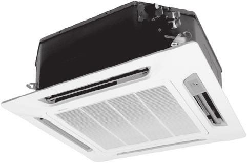
4 Table of Contents Fan coil units OEM Low wall / Flexi type unit... 1 FWV-FWL-FWM... 4 Duct Unit... 2 FWD Small Duct Unit... FWB Ceiling mounted cassette unit... 4 FWC Ceiling mounted cassette unit... 5 FWF Wall mounted unit... 6 FWT Fan coil units Table of Contents 2
5
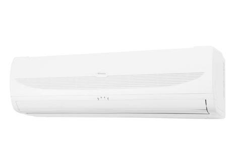
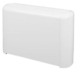
6 Fan coil units Low wall / Flexi type unit FWV-FWL-FWM TABLE OF CONTENTS FWV-FWL-FWM Low wall / Flexi type unit FWV-FWL-FWM 1 Features Specifications Nominal capacity and nominal input Technical Specifications Electrical Specifications Options Control systems Capacity tables Cooling capacity tables - 2-pipe Cooling capacity tables - 4-pipe Capacity tables with glycol for process cooling applications Heating capacity tables - 2-pipe Heating capacity tables - 4-pipe Power consumption - 2-pipe Power consumption - 4-pipe Capacity correction factor Dimensional drawing & centre of gravity Dimensional drawing Wiring diagram Wiring diagram Sound data Sound level data Installation Installation method Operation range Hydraulic performance Water pressure drop curve evaporator cooling 2-pipe Water pressure drop curve evaporator heating 2-pipe Water pressure drop curve evaporator heating 4-pipe Hydronic Systems Fan coil units 4


7 sn yu l l F c l i - i a ol n c o F r - n d oa y F L Fan coil units Low wall / Flexi type unit FWV-FWL-FWM 1 Features / SM W Ww w V W H Quick fixing system for wall mounting Pre-assembled -way/4-port ON/OFF valves are available Valve packages are insulated, no extra drain pan required Valve packages contain balancing valves and sensor pocket Fast-on connections for electrical options : no tools needed Quick removal of washable filter Electrical heater : no relay up to 2kw capacity Electrical heater : equipped with two overheat cut-out thermostats Hydronic Systems Fan coil units
8 Fan coil units Low wall / Flexi type unit FWV-FWL-FWM 2 Specifications 2-1 NOMINAL CAPACITY AND NOMINAL INPUT FWV-L-M 01CATN/TV FWV-L-M 02CATN/TV FWV-L-M 0CATN/TV FWV-L-M 04CATN/TV FWV-L-M 06CATN/TV FWV-L-M 08CATN/TV FWV-L-M 10CATN/TV Power Input High W Medium W Low W Cooling capacity Total capacity High kw Medium kw Low kw Sensible capacity High kw Medium kw Low kw Heating capacity High kw (2-pipe) Medium kw Low kw NOMINAL CAPACITY AND NOMINAL INPUT FWV-L-M 01CAFN/FV FWV-L-M 02CAFN/FV FWV-L-M 0CAFN/FV FWV-L-M 04CAFN/FV FWV-L-M 06CAFN/FV FWV-L-M 08CAFN/FV FWV-L-M 10CAFN/FV Power Input High W Medium W Low W Cooling capacity Total capacity High kw Medium kw Low kw Sensible capacity High kw Medium kw Low kw Heating capacity High kw (4-pipe) Medium kw Low kw Hydronic Systems Fan coil units 6
9 2 Specifications Fan coil units Low wall / Flexi type unit FWV-FWL-FWM TECHNICAL SPECIFICATIONS FWV-L-M 01CATN/TV FWV-L-M 02CATN/TV FWV-L-M 0CATN/TV FWV-L-M 04CATN/TV FWV-L-M 06CATN/TV FWV-L-M 08CATN/TV FWV-L-M 10CATN/TV Dimensions Unit - FWV Height mm Width mm Depth mm Unit - FWL Height mm Width mm Depth mm Unit - FWM Height mm Width mm Depth mm Weight Machine weight - FWV kg Machine weight - FWL kg Machine weight - FWM kg Material Plastic + sheet metal Colour Plastic and metal RAL9010 Sound level Sound power High dba Medium dba Low dba Water flow Cooling l/h Heating l/h Water pressure drop Cooling kpa Heating kpa Fan Type Centrifugal multi-blade, double suction Air flow rate High m³/h Medium m³/h Low m³/h Speed steps : high, medium, low Quantity Motor Type Closed induction, B class insulation, winding thermal cut-out Standard heat Rows mm 2 exchanger Stages mm Fin pitch mm Face area m² Water volume l Air filter Plastic Insulation material Class 1 self-extinguishing Vibration insulation Rubber ring for fan motor Water connections Std. heat exchanger inch 1/2 1/2 1/2 1/2 1/2 /4 /4 Drain mm Notes Cooling capacity is based on room temperature 27 CDB, 19 CWB and entering water temperature 7 C, water temperature rise 5K. Heating capacity is based on: room temperatue 20 CDB and entering water temperature 50 C, water flow rate as during cooling. Air flow at 0 Pa ESP 7 Hydronic Systems Fan coil units
10 Fan coil units Low wall / Flexi type unit FWV-FWL-FWM 2 Specifications 2-2 TECHNICAL SPECIFICATIONS FWV-L-M 01CAFN/FV FWV-L-M 02CAFN/FV FWV-L-M 0CAFN/FV FWV-L-M 04CAFN/FV FWV-L-M 06CAFN/FV FWV-L-M 08CAFN/FV FWV-L-M 10CAFN/FV Dimensions Unit - FWV Height mm Width mm Depth mm Unit - FWL Height mm Width mm Depth mm Unit - FWM Height mm Width mm Depth mm Weight Machine weight - FWV kg Machine weight - FWL kg Machine weight - FWM kg Material Plastic + sheet metal Colour Plastic and metal RAL9010 Sound level Sound power High dba Medium dba Low dba Water flow Cooling l/h Heating l/h Water pressure drop Cooling kpa Heating kpa Fan Type Centrifugal multi-blade, double suction Air flow rate High m³/h Medium m³/h Low m³/h Speed steps : high, medium, low Quantity Motor Type Closed induction, B class insulation, winding thermal cut-out Standard heat Rows mm 2 exchanger Stages mm Fin pitch mm Face area m² Water volume l Additional heat Rows mm exchanger Stages mm Fin pitch mm Face area m² Water volume l Air filter Plastic Insulation material Class 1 self-extinguishing Vibration insulation Rubber ring for fan motor Water connections Std. heat exchanger inch 1/2 1/2 1/2 1/2 1/2 /4 /4 Drain mm Notes Rating conditions cooling 4 pipe : air 27 Rating conditions heating 4 pipe : air 20 Air flow at 0 Pa ESP 1 2 Hydronic Systems Fan coil units 8
11 2 Specifications Fan coil units Low wall / Flexi type unit FWV-FWL-FWM ELECTRICAL SPECIFICATIONS FWV-L-M 01CATN/TV FWV-L-M 02CATN/TV FWV-L-M 0CATN/TV FWV-L-M 04CATN/TV FWV-L-M 06CATN/TV FWV-L-M 08CATN/TV FWV-L-M 10CATN/TV Current input High A Medium A Low A Required power supply V / f / Hz 20/1/50 Required fuses A Required wire section mm² Notes The power consumption for the valve motor is 5W (peak) only during opening For more details concerning conditional connections, see select E- data Books. Finally click on the document title of your choice 2- ELECTRICAL SPECIFICATIONS FWV-L-M 01CAFN/FV FWV-L-M 02CAFN/FV FWV-L-M 0CAFN/FV FWV-L-M 04CAFN/FV FWV-L-M 06CAFN/FV FWV-L-M 08CAFN/FV FWV-L-M 10CAFN/FV Current input High A l Medium A Low A Required power supply V / f / Hz 20/1/50 Required fuses A Required wire section mm² Notes The power consumption for the valve motor is 5W (peak) only during opening For more details concerning conditional connections, see select E- data Books. Finally click on the document title of your choice 9 Hydronic Systems Fan coil units
12 Fan coil units Low wall / Flexi type unit FWV-FWL-FWM Options FWV - FWL - FWM F2 F4 F6 F8 F9 F10 F11 FWV FWL FWM Notes/remarks Additional single-row heat exchanger ESRH..A6 ESRH02A6 ESRH0A6 ESRH06A6 ESRH10A6 X X X Cannot be used in combination with electric heater Cannot be used in combination with additional H/E requires electronic controller Electric heater EEH..A6 EEH01A6 EEH02A6 EEH0A6 EEH06A6 EEH10A6 X X X E2MV..A6 E2MV0A6 E2MV06A6 E2MV10A6 X X X Requires electronic controller or electromechanical controller 2-pipe ON-OFF way motor driven valve complete with mounting kit E4MV..A6 E4MV0A6 E4MV06A6 E4MV10A6 X X X Requires electronic controller 4-pipe ON-OFF way motor driven valve complete with mounting kit Fan stop thermostat YFSTA6 YFSTA6 X X X EAIDF..A6 EAIDF02A6 EAIDF0A6 EAIDF06A6 EAIDF10A6 X Air intake & discharge grill + front filter fixing kit for concealed models Supporting feet feet (= supporting brackets + covers) ESFV..A6 ESFV06A6 ESFV10A6 X X Covers can not be used for FWM Supporting feet + grill ESFVG..A6 ESFVG02A6 ESFVG0A6 ESFVG06A6 ESFVG10A6 X Fresh air intake louvers (manual) EFA..A6 EFA02A6 EFAA6 EFA6A6 EFA10A6 X Rear panel for vertical mounted models ERPV..A6 ERPV2A6 ERPV0A6 ERPV06A6 ERPV10A6 X X Only for vertical mounted units Controller electro mechanical built in ECFWMB6 ECFWMB6 X X X Controller electronical built in + water probe ECFWEB6 ECFWEB6 X X X Water probe included Controller electronical remote + water probe ECFWER6 ECFWER6 X X X Water probe included EPIMSA6 EPIMSA6 X X X Power interface for connection of up to 4 FCU to a single control panel Vertical drain pan EDPVA6 EDPVA6 X X X Horizontal drain pan EDPHA6 EDPHA6 X X 4TW A (Sheet 1/2) 1 Hydronic Systems Fan coil units 10
13 Fan coil units Low wall / Flexi type unit FWV-FWL-FWM Options 1 Vertical drain pan Horizontal drain pan Power interface for connection of up to 4 FCU to a single control panel Controller electronical remote + water probe Controller electronical built in Controller electro mechanical built in Rear panel for vertical mounted models Fresh air intake louvers (manual) Supporting feet + grill Supporting feet feet (= supporting brackets + covers) Air intake & discharge grill + front filter fixing kit for concealed models Fan stop thermostat 4-pipe ON-OFF way motor driven valve complete with mounting kit Electric heater 2-pipe ON-OFF way motor driven valve complete with mounting kit FWV Additional single-row heat exchanger ESRH..A6 EEH..A6 E2MV..A6 E4MV..A6 YFSTA6 EAIDF..A6 ESFV..A6 ESFVG..A6 EFA..A6 ERPV..A6 ECFWMB6 ECFWEB6 ECFWER6 EPIMSA6 EDPVA6 EDPHA6 Additional single-row heat exchanger ESRH..A6 X X X X X X X X X X X Electric heater EEH..A6 X X X X X X X X X X X E2MV..A6 X X X X X X X X X X X X 2-pipe ON-OFF way motor driven valve complete with mounting kit E4MV..A6 X X X X X X X X X X X 4-pipe ON-OFF way motor driven valve complete with mounting kit Fan stop thermostat YFSTA6 X X X X X X X X X EAIDF..A6 X X X X X X X X X X X X Air intake & discharge grill + front filter fixing kit for concealed models ESFV..A6 X X X X X X X X X X X X X X Supporting feet feet (= supporting brackets + covers) Supporting feet + grill ESFVG..A6 X X X X X X X X X X X X X X Fresh air intake louvers (manual) EFA..A6 X X X X X X X X X X X X X X Rear panel for vertical mounted models ERPV..A6 X X X X X X X X X X X X X X X Controller electro mechanical built in ECFWMB6 X X X X X X X x X Controller electronical built in ECFWEB6 X X X X X X X X X X X Controller electronical remote + water probe ECFWER6 X X X X X X X X X X X X EPIMSA6 X X X X X X X X X X X X X X X Power interface for connection of up to 4 FCU to a single control panel Verticaldrainpan EDPVA6 X X X X X X X X X X X X X X Horizontaldrainpan EDPHA6 X X X X X X X X X X X X X X 4TW A (Sheet 2/2) 11 Hydronic Systems Fan coil units
14 4 Control systems Fan coil units Low wall / Flexi type unit FWV-FWL-FWM 4-pipe 2-pipe Cool/heat changeover Options Basic control functions Control features 7 X X X X X X X X X X X X X X X X X X X X X X X X X X X X X X X X X X X X X X X X X X X X X X X X X X X X X X X X X X X X X X X X X 1 4 Manual cool/heat changeover. Automatic cool/heat changeover based on water temperature. Automatic cool/heat changeover based on air temperature. Control of the -way/4pipe ON/OFF valve. The water valve shut-off once the desired temperature is reached. The controller controls the electric heater as integration or replacement of the hot water heating system. When the operating mode selector witch is turned on electric heater and the electric heater is turned on, the fan runs continuously at medium speed. When the operating mode selector switch is turned to electric heater and the electric heater is turned on, the fan runs continuously at medium speed. The fan speed can be set at one of the speeds (low, medium or maximum) by turning the operation mode selector. 7 The fan speed is switched automatically based on the difference between the temperature set on the thermostat and the room temperature. Optimised comfort cooling. When the fan coil has reached the desired setpoint, the fan will operate at medium speed and at regular intervals to ensure constant room temperature and lower sound. The controller prevents the fan coil unit from operating in one mode, if the required water temperature is not achieved to operate in the selected mode. The dead zone is a temperature interval close to the set temperature. When the air is warmer/cooler than the top/lower limit of the neutral zone, the cooling/heating mode is selected. Hydronic Systems Fan coil units 12
15 5 Capacity tables 5-1 Cooling capacity tables - 2-pipe Fan coil units Low wall / Flexi type unit FWV-FWL-FWM 1 5 Air temperature ( C DB - C WB) Water temperature (Entering C - leaving C) Model Total cooling capacity Sensible cooling capacity Water flow Water pressure drop Total cooling capacity Sensible cooling capacity Water flow Water pressure drop Total cooling capacity Sensible cooling capacity Water flow Water pressure drop Total cooling capacity Sensible cooling capacity Water flow Water pressure drop W W!/h kpa W W!/h kpa W W!/h kpa W W!/h kpa FW 01 TN/TV Max Med Min FW 02 TN/TV Max Med Min FW 0 TN/TV Max Med Min FW 04 TN/TV Max Med Min FW 06 TN/TV Max Med Min FW 08 TN/TV Max Med Min FW 10 TN/TV Max Med Min TW A (Sheet 1/1) 1 Hydronic Systems Fan coil units
16 5 Capacity tables 5-1 Cooling capacity tables - 2-pipe Fan coil units Low wall / Flexi type unit FWV-FWL-FWM Air temperature ( C DB - C WB) Water temperature (Entering C - leaving C) Model Total cooling capacity Sensible cooling capacity Water flow Water pressure drop Total cooling capacity Sensible cooling capacity Water flow Water pressure drop Total cooling capacity Sensible cooling capacity Water flow Water pressure drop Total cooling capacity Sensible cooling capacity Water flow Water pressure drop W W!/h kpa W W!/h kpa W W!/h kpa W W!/h kpa FW 01 TN/TV Max Med Min FW 02 TN/TV Max Med Min FW 0 TN/TV Max Med Min FW 04 TN/TV Max Med Min FW 06 TN/TV Max Med Min FW 08 TN/TV Max Med Min FW 10 TN/TV Max Med Min TW A (Sheet /1) 1 5 Hydronic Systems Fan coil units 14
17 5 Capacity tables 5-1 Cooling capacity tables - 2-pipe Fan coil units Low wall / Flexi type unit FWV-FWL-FWM 1 5 Air temperature ( C DB - C WB) Water temperature (Entering C - leaving C) Model Total cooling capacity Sensible cooling capacity Water flow Water pressure drop Total cooling capacity Sensible cooling capacity Water flow Water pressure drop Total cooling capacity Sensible cooling capacity Water flow Water pressure drop Total cooling capacity Sensible cooling capacity Water flow Water pressure drop W W!/h kpa W W!/h kpa W W!/h kpa W W!/h kpa FW 01 TN/TV Max Med Min FW 02 TN/TV Max Med Min FW 0 TN/TV Max Med Min FW 04 TN/TV Max Med Min FW 06 TN/TV Max Med Min FW 08 TN/TV Max Med Min FW 10 TN/TV Max Med Min TW A (Sheet 5/1) 15 Hydronic Systems Fan coil units
18 5 Capacity tables 5-1 Cooling capacity tables - 2-pipe Fan coil units Low wall / Flexi type unit FWV-FWL-FWM Air temperature ( C DB - C WB) 0-22 Water temperature (Entering C - leaving C) Model Total cooling capacity Sensible cooling capacity Water flow Water pressure drop Total cooling capacity Sensible cooling capacity Water flow Water pressure drop Total cooling capacity Sensible cooling capacity Water flow Water pressure drop Total cooling capacity Sensible cooling capacity Water flow Water pressure drop W W!/h kpa W W!/h kpa W W!/h kpa W W!/h kpa FW 01 TN/TV Max Med Min FW 02 TN/TV Max Med Min FW 0 TN/TV Max Med Min FW 04 TN/TV Max Med Min FW 06 TN/TV Max Med Min FW 08 TN/TV Max Med Min FW 10 TN/TV Max Med Min TW A (Sheet 7/1) 1 5 Hydronic Systems Fan coil units 16
19 5 Capacity tables 5-2 Cooling capacity tables - 4-pipe Fan coil units Low wall / Flexi type unit FWV-FWL-FWM 1 5 Air temperature ( C DB - C WB) Water temperature (Entering C - leaving C) Model Total cooling capacity Sensible cooling capacity Water flow Water pressure drop Total cooling capacity Sensible cooling capacity Water flow Water pressure drop Total cooling capacity Sensible cooling capacity Water flow Water pressure drop Total cooling capacity Sensible cooling capacity Water flow Water pressure drop W W!/h kpa W W!/h kpa W W!/h kpa W W!/h kpa FW 01 FN/FV Max Med Min FW 02 FN/FV Max Med Min FW 0 FN/FV Max Med Min FW 04 FN/FV Max Med Min FW 06 FN/FV Max Med Min FW 08 FN/FV Max Med Min FW 10 TN/TV Max Med Min TW A (Sheet 2/1) 17 Hydronic Systems Fan coil units
20 5 Capacity tables 5-2 Cooling capacity tables - 4-pipe Fan coil units Low wall / Flexi type unit FWV-FWL-FWM Air temperature ( C DB - C WB) Water temperature (Entering C - leaving C) Model Total cooling capacity Sensible cooling capacity Water flow Water pressure drop Total cooling capacity Sensible cooling capacity Water flow Water pressure drop Total cooling capacity Sensible cooling capacity Water flow Water pressure drop Total cooling capacity Sensible cooling capacity Water flow Water pressure drop W W!/h kpa W W!/h kpa W W!/h kpa W W!/h kpa FW 01 FN/FV Max Med Min FW 02 FN/FV Max Med Min FW 0 FN/FV Max Med Min FW 04 FN/FV Max Med Min FW 06 FN/FV Max Med Min FW 08 FN/FV Max Med Min FW 10 TN/TV Max Med Min TW A (Sheet 4/1) 1 5 Hydronic Systems Fan coil units 18
21 5 Capacity tables 5-2 Cooling capacity tables - 4-pipe Fan coil units Low wall / Flexi type unit FWV-FWL-FWM 1 5 Air temperature ( C DB - C WB) Water temperature (Entering C - leaving C) Model Total cooling capacity Sensible cooling capacity Water flow Water pressure drop Total cooling capacity Sensible cooling capacity Water flow Water pressure drop Total cooling capacity Sensible cooling capacity Water flow Water pressure drop Total cooling capacity Sensible cooling capacity Water flow Water pressure drop W W!/h kpa W W!/h kpa W W!/h kpa W W!/h kpa FW 01 FN/FV Max Med Min FW 02 FN/FV Max Med Min FW 0 FN/FV Max Med Min FW 04 FN/FV Max Med Min FW 06 FN/FV Max Med Min FW 08 FN/FV Max Med Min FW 10 TN/TV Max Med Min TW A (Sheet 6/1) 19 Hydronic Systems Fan coil units
22 5 Capacity tables 5-2 Cooling capacity tables - 4-pipe Fan coil units Low wall / Flexi type unit FWV-FWL-FWM Air temperature ( C DB - C WB) 0-22 Water temperature (Entering C - leaving C) Model Total cooling capacity Sensible cooling capacity Water flow Water pressure drop Total cooling capacity Sensible cooling capacity Water flow Water pressure drop Total cooling capacity Sensible cooling capacity Water flow Water pressure drop Total cooling capacity Sensible cooling capacity Water flow Water pressure drop W W!/h kpa W W!/h kpa W W!/h kpa W W!/h kpa FW 01 FN/FV Max Med Min FW 02 FN/FV Max Med Min FW 0 FN/FV Max Med Min FW 04 FN/FV Max Med Min FW 06 FN/FV Max Med Min FW 08 FN/FV Max Med Min FW 10 TN/TV Max Med Min TW A (Sheet 8/1) 1 5 Hydronic Systems Fan coil units 20
23 5 Capacity tables Fan coil units Low wall / Flexi type unit FWV-FWL-FWM 5 - Capacity tables with glycol for process cooling applications 1 5 Cooling mode Glycol percentage in weight Freezing temperature ( C) Capacity correction factor Pressure drop correction factor Heating mode Glycol percentage in weight Freezing temperature ( C) Capacity correction factor Pressure drop correction factor TW B Correction factors are based on an average value (at rated water flow rate). This can cause deviation depending on conditions used. The Fan Coil Selection software will provide an accurate result at all conditions. 21 Hydronic Systems Fan coil units
24 5 Capacity tables 5-4 Heating capacity tables - 2-pipe Fan coil units Low wall / Flexi type unit FWV-FWL-FWM Air temperature ( C) 20 Water temperature (Entering C - leaving C) Model Heating capacity Water flow Water pressure drop Heating capacity Water flow Water pressure drop Heating capacity Water flow Water pressure drop Heating capacity Water flow Water pressure drop W!/h kpa W!/h kpa W!/h kpa W!/h kpa FW 01 TN/TV Max Med Min FW 02 TN/TV Max Med Min FW 0 TN/TV Max Med Min FW 04 TN/TV Max Med Min FW 06 TN/TV Max Med Min FW 08 TN/TV Max Med Min FW 10 TN/TV Max Med Min TW A (Sheet 9/1) 1 5 Hydronic Systems Fan coil units 22
25 5 Capacity tables 5-4 Heating capacity tables - 2-pipe Fan coil units Low wall / Flexi type unit FWV-FWL-FWM 1 5 Air temperature ( C) 22 Water temperature (Entering C - leaving C) Model Heating capacity Water flow Water pressure drop Heating capacity Water flow Water pressure drop Heating capacity Water flow Water pressure drop Heating capacity Water flow Water pressure drop W!/h kpa W!/h kpa W!/h kpa W!/h kpa FW 01 TN/TV Max Med Min FW 02 TN/TV Max Med Min FW 0 TN/TV Max Med Min FW 04 TN/TV Max Med Min FW 06 TN/TV Max Med Min FW 08 TN/TV Max Med Min FW 10 TN/TV Max Med Min TW A (Sheet 10/1) 2 Hydronic Systems Fan coil units
26 5 Capacity tables 5-5 Heating capacity tables - 4-pipe Fan coil units Low wall / Flexi type unit FWV-FWL-FWM Air temperature ( C) 20 Water temperature (Entering C - leaving C) Model Air flow Heating capacity Water flow Water pressure drop Heating capacity Water flow Water pressure drop Heating capacity Water flow Water pressure drop Heating capacity Water flow Water pressure drop m /h W!/h kpa W!/h kpa W!/h kpa W!/h kpa FW 01 FN/FV Max Med Min FW 02 FN/FV Max Med Min FW 0 FN/FV Max Med Min FW 04 FN/FV Max Med Min FW 06 FN/FV Max Med Min FW 08 FN/FV Max Med Min FW 10 TN/TV Max Med Min TW A (Sheet 11/1) 1 5 Hydronic Systems Fan coil units 24
27 5 Capacity tables 5-5 Heating capacity tables - 4-pipe Fan coil units Low wall / Flexi type unit FWV-FWL-FWM 1 5 Air temperature ( C) 22 Water temperature (Entering C - leaving C) Model Heating capacity Water flow Water pressure drop Heating capacity Water flow Water pressure drop Heating capacity Water flow Water pressure drop Heating capacity Water flow Water pressure drop W!/h kpa W!/h kpa W!/h kpa W!/h kpa FW 01 FN/FV Max Med Min FW 02 FN/FV Max Med Min FW 0 FN/FV Max Med Min FW 04 FN/FV Max Med Min FW 06 FN/FV Max Med Min FW 08 FN/FV Max Med Min FW 10 TN/TV Max Med Min TW A (Sheet 12/1) 25 Hydronic Systems Fan coil units
28 Fan coil units Low wall / Flexi type unit FWV-FWL-FWM 5 Capacity tables 5-6 Power consumption - 2-pipe FW..01 Max. Med. Min. ESP Power input Current Power input Current Power input Current (Pa) (W) (A) (W) (A) (W) (A) 0 7 0, , , , , , , , , , , , ,140 4TW A (2/15) FW..02 Max. Med. Min. ESP Power input Current Power input Current Power input Current (Pa) (W) (A) (W) (A) (W) (A) TW A (/15) 1 5 FW..0 Max. Med. Min. ESP Power input Current Power input Current Power input Current (Pa) (W) (A) (W) (A) (W) (A) TW A (4/15) FW..04 Max. Med. Min. ESP Power input Current Power input Current Power input Current (Pa) (W) (A) (W) (A) (W) (A) TW A (5/15) ESP: _SYMBOLS External static pressure Hydronic Systems Fan coil units 26
29 5 Capacity tables 5-6 Power consumption - 2-pipe Fan coil units Low wall / Flexi type unit FWV-FWL-FWM 1 5 FW..06 Max. Med. Min. ESP Power input Current Power input Current Power input Current (Pa) (W) (A) (W) (A) (W) (A) TW A (6/15) FW..08 Max. Med. Min. ESP Power input Current Power input Current Power input Current (Pa) (W) (A) (W) (A) (W) (A) TW A (7/15) FW..10 Max. Med. Min. ESP Power input Current Power input Current Power input Current (Pa) (W) (A) (W) (A) (W) (A) TW A (8/15) ESP: SYMBOLS External static pressure 27 Hydronic Systems Fan coil units
30 Fan coil units Low wall / Flexi type unit FWV-FWL-FWM 5 Capacity tables 5-7 Power consumption - 4-pipe FW..01 Max. Med. Min. ESP Power input Current Power input Current Power input Current (Pa) (W) (A) (W) (A) (W) (A) TW A (9/15) FW..02 Max. Med. Min. ESP Power input Current Power input Current Power input Current (Pa) (W) (A) (W) (A) (W) (A) TW A (10/15) 1 5 FW..0 Max. Med. Min. ESP Power input Current Power input Current Power input Current (Pa) (W) (A) (W) (A) (W) (A) TW A (11/15) FW..04 Max. Med. Min. ESP Power input Current Power input Current Power input Current (Pa) (W) (A) (W) (A) (W) (A) TW A (12/15) ESP: SYMBOLS External static pressure Hydronic Systems Fan coil units 28
31 5 Capacity tables 5-7 Power consumption - 4-pipe Fan coil units Low wall / Flexi type unit FWV-FWL-FWM 1 5 FW..06 Max. Med. Min. ESP Power input Current Power input Current Power input Current (Pa) (W) (A) (W) (A) (W) (A) TW A (1/15) FW..08 Max. Med. Min. ESP Power input Current Power input Current Power input Current (Pa) (W) (A) (W) (A) (W) (A) TW A (14/15) FW..10 Max. Med. Min. ESP Power input Current Power input Current Power input Current (Pa) (W) (A) (W) (A) (W) (A) TW A (15/15) ESP: SYMBOLS External static pressure 29 Hydronic Systems Fan coil units
32 5 Capacity tables 5-8 Capacity correction factor Fan coil units Low wall / Flexi type unit FWV-FWL-FWM FWV - FWL - FWM ESP Fan speed F1 F2 F1 F2 F1 F2 F1 F2 F1 F2 F1 F2 FW..01 Max Med Min FW..02 Max Med Min FW..0 Max Med Min FW..04 Max Med Min FW..06 Max Med Min FW..08 Max Med Min FW..10 Max Med Min FW..01 FW..02 FW..0 FW..04 FW..06 FW..08 FW..10 medium low medium low medium low medium low medium low medium low medium low Total cooling capacity TCC Sensible cooling capacity SCC Heating capacity - 2 pipe HC2P Heating capacity - 4 pipe HC TW Conditions Cooling Air: 27 C DB - 19 C WB - Water: entering 7 C - leaving 12 C F1 = correction factor for air flow Heating 2-pipe Air: 20 C Water: entering 50 C water flow as for cooling F2 = correction factor for capacities Heating 4-pipe Air: 20 C Water: entering 70 C - leaving 60 C Correction factors are based on an average value. This can cause deviation depending on conditions used. The Fan Coil Selection software will provide an accurate result at all conditions. 1 5 Hydronic Systems Fan coil units 0
33 Fan coil units Low wall / Flexi type unit FWV-FWL-FWM 6 Dimensional drawing & centre of gravity 6-1 Dimensional drawing FWV-FWL 1 6 A B C D E F G H L M N P R S T Z FWV+FWL FWV+FWL FWV+FWL FWV+FWL Legend 1 Clear space for hydraulic connections (*) 2 Slots for wall / ceiling mounting 9x20mm Clear space for electric connections (*) 4 Hydraulic connections (4DF = 4 pipe system) 5 Condensate drainage for vertical installation 6 Air outlet for concealed models 7 Air suction for concealed models 8 Condensate drainage for horizontal installation 9 Air outlet 10 Air inlet Hydraulic connections Standard heat exchanger: connection female FW01 FW02 FW0 FW04 FW06 FW08 FW10 1/2 1/2 1/2 1/2 1/2 /4 /4 Additional heat exchanger: connection female FW01 FW02 FW0 FW04 FW06 FW08 FW10 1/2 1/2 1/2 1/2 1/2 1/2 1/2 (*) Indications applicable to fan coils with hydraulic connections on the left side; in case of right side connections the indications for clear space are reversed. 4TW A (Sheet 1/2) 1 Hydronic Systems Fan coil units
34 Fan coil units Low wall / Flexi type unit FWV-FWL-FWM 6 Dimensional drawing & centre of gravity 6-1 Dimensional drawing FWM 1 6 A B C D E F G H L M N P Q R S T U V W FWM FWM FWM FWM Required installation space Keep at least 100 mm of free space at air inlet for a proper air suction and an easy removal of the filter. For ducted units the outlet/inlet grill surface must be at least equal to the outlet/inlet surface of the unit to avoid extra noise and strong performance reduction. Legend 1 Clear space for hydraulic connections (*) 2 Slots for wall / ceiling mounting 9x20mm Clear space for electric connections (*) 4 Hydraulic connections (4DF = 4 pipe system) 5 Condensate drainage for vertical installation 6 Air outlet for concealed models 7 Air suction for concealed models 8 Condensate drainage for horizontal installation 9 Air outlet 10 Air inlet Hydraulic connections Standard heat exchanger: connection female FW01 FW02 FW0 FW04 FW06 FW08 FW10 1/2 1/2 1/2 1/2 1/2 /4 /4 Additional heat exchanger: connection female FW01 FW02 FW0 FW04 FW06 FW08 FW10 1/2 1/2 1/2 1/2 1/2 1/2 1/2 (*) Indications applicable to fan coils with hydraulic connections on the left side; in case of right side connections the indications for clear space are reversed. 4TW A (Sheet 2/2) Hydronic Systems Fan coil units 2
35 7 Wiring diagram 7-1 Wiring diagram Fan coil units Low wall / Flexi type unit FWV-FWL-FWM 1 7 SYMBOLS BK Black = maximum speed BU Blue = medium speed GNYE Yellow/Green = earth connection RD Red = minimum speed WH White = common ---- Field wiring F Protection fuse (field supply) IL Main switch (field supply) M Fan motor PE Earth connection 4TW Hydronic Systems Fan coil units
36 Fan coil units Low wall / Flexi type unit FWV-FWL-FWM 8 Sound data 8-1 Sound level data Sound power level and Spectrum FW01 TN/TV Sound Power Levels db(a) 125 HZ 250 Hz 500 Hz 1000 Hz 2000 Hz 4000 Hz 8000 Hz Global Lw Max Med Min FW02 TN/TV Sound Power Levels db(a) 125 Hz 250 Hz 500 Hz 1000 Hz 2000 Hz 4000 Hz 8000 Hz Global Lw Max Med Min FW0 TN/TV Sound Power Levels db(a) 125 Hz 250 Hz 500 Hz 1000 Hz 2000 Hz 4000 Hz 8000 Hz Global Lw Max Med Min FW04 TN/TV Sound Power Levels db(a) 125 Hz 250 Hz 500 Hz 1000 Hz 2000 Hz 4000 Hz 8000 Hz Global Lw Max Med Min FW06 TN/TV Sound Power Levels db(a) 125 Hz 250 Hz 500 Hz 1000 Hz 2000 Hz 4000 Hz 8000 Hz Global Lw Max Med Min FW08 TN/TV Sound Power Levels db(a) 125 Hz 250 Hz 500 Hz 1000 Hz 2000 Hz 4000 Hz 8000 Hz Global Lw Max Med Min FW10 TN/TV Sound Power Levels db(a) 125 Hz 250 Hz 500 Hz 1000 Hz 2000 Hz 4000 Hz 8000 Hz Global Lw Max Med Min Conditions of measurements in case of (M) models the sound power is calculated WITHOUT any additional inlet or outlet grill or plenum! 4TW A (Sheet 1/2) 1 8 To calculate the sound pressure you must define some conditions and use this formula 4π xd2 L p =L w -10xLog 10 ( Q ) Where: Q = direction factor: is Q=4 if the FCU is installed near 2 walls (vertical or floor-ceiling), Q=2 if the FCU is installed near 1 wall (at floor or ceiling but faraway the 2nd wall) d = distance (mt) from the sound source and the measure point LP = Sound pressure (dba) Lw = Sound power (dba) Hydronic Systems Fan coil units 4
37 Fan coil units Low wall / Flexi type unit FWV-FWL-FWM 8 Sound data 8-1 Sound level data 1 8 Sound power level and Spectrum FW01 FN/TV Sound Power Levels db(a) 125 HZ 250 Hz 500 Hz 1000 Hz 2000 Hz 4000 Hz 8000 Hz Global Lw Max Med Min FW02 FN/TV Sound Power Levels db(a) 125 Hz 250 Hz 500 Hz 1000 Hz 2000 Hz 4000 Hz 8000 Hz Global Lw Max Med Min FW0 FN/TV Sound Power Levels db(a) 125 Hz 250 Hz 500 Hz 1000 Hz 2000 Hz 4000 Hz 8000 Hz Global Lw Max Med Min FW04 FN/TV Sound Power Levels db(a) 125 Hz 250 Hz 500 Hz 1000 Hz 2000 Hz 4000 Hz 8000 Hz Global Lw Max Med Min FW06 FN/TV Sound Power Levels db(a) 125 Hz 250 Hz 500 Hz 1000 Hz 2000 Hz 4000 Hz 8000 Hz Global Lw Max Med Min FW08 FN/TV Sound Power Levels db(a) 125 Hz 250 Hz 500 Hz 1000 Hz 2000 Hz 4000 Hz 8000 Hz Global Lw Max Med Min FW10 FN/TV Sound Power Levels db(a) 125 Hz 250 Hz 500 Hz 1000 Hz 2000 Hz 4000 Hz 8000 Hz Global Lw Max Med Min Conditions of measurements in case of (M) models the sound power is calculated WITHOUT any additional inlet or outlet grill or plenum! 4TW A (Sheet 2/2) To calculate the sound pressure you must define some conditions and use this formula 4π xd2 L p =L w -10xLog 10 ( Q ) Where: Q = direction factor: is Q=4 if the FCU is installed near 2 walls (vertical or floor-ceiling), Q=2 if the FCU is installed near 1 wall (at floor or ceiling but faraway the 2nd wall) d = distance (mt) from the sound source and the measure point LP = Sound pressure (dba) Lw = Sound power (dba) 5 Hydronic Systems Fan coil units
38 9 Installation 9-1 Installation method Fan coil units Low wall / Flexi type unit FWV-FWL-FWM Fan coil units should be installed in a position where they heat and cool the room evenly, on walls or ceilings that can bear their weight. Fit any accessories on the standard unit before installing it. Read the relevant technical sheets for the installation and use of the accessories. Keep free space around the fan coil to allow proper operation and ordinary and extraordinary maintenance (see the 9. Dimensional drawings ) Provide a panel to reach the unit in case of recessed mounting (Concealed models). Install the remote control panel, if any, in a position that can easily be reached by the user to set the functions and that is suitable for the proper detection of the temperature, if provided. Therefore avoid: - positions directly exposed to sunlight; - positions exposed to hot or cold draughts; - obstacles preventing the proper temperature detection If the system is shut down during the winter months, drain off the water from the system to prevent damage due to freezing; if antifreeze solutions are used, check the freezing point using the table shown on technical manual. Keep at least 100 mm of free space at air inlet for a proper air suction and an easy removal of the filter. For ducted units the outlet/inlet grill surface must be at least equal to the outlet/inlet surface of the unit to avoid extra noise and strong performance reduction. 1 9 BEFORE THE INSTALLATION Installation and maintenance should be carried out by technical personnel qualified for this type of machine, in compliance with current safety regulations. For installation and use of possible accessories please refer to the pertinent technical sheets. In choosing where to install the unit, comply with the following points: - the heating unit should not be placed immediately under a socket - do not install the unit in rooms where inflammable gases are present - do not let water is sprayed directly on the unit - install the unit on ceilings or walls that bear its weight. Leave enough space all around for proper operation and maintenance of the unit. Keep the unit in its packaging until it is ready to be installed, to prevent dust getting inside it. INSTALLATION WARNING: On the fan coil install a switch (IL) and/or all remote controls in a position out of the reach of persons who are in a bathtub or shower. In case of ceiling-mounted models, check that the installation height does not exceed the maximum height shown in 7. Dimensional drawings in order to avoid excessive hot air stratification in the upper part of the room; in case of greater installation heights we suggest to proceed with the back suction from the lower part of the room. The installation heights shown in the figure refer to the maximum running speed. Carry out the hydraulic connections to the heat exchanger and in case of cooling operation, to the water drainage system. We suggest to provide for the water inlet from the bottom side of the heat exchanger and the outlet on the upper side. Bleed the air from the heat exchanger operating on the air-vent valves (10 hexagon wrench) located beside the water connections of the heat exchanger. For a better water drainage lean the drain pipe downwards at least cm/m avoiding loops or narrowing on its way. INSTALLATION FOR THE CONCEALED CEILING MODEL The air outlets should not be placed immediately under a socket. For the concealed ceiling model, perform the connection between the fan coil and the ducts, and place damping material between the duct and the unit. The ducts, in particular the outlet ones, must be insulated. In order to avoid air back suction on the fan coil, keep a minimum distance between the air outlet and recovered air flow as shown in installation manual of the unit. The minimum installation height should not be lower than 1.8 metres from floor level. Provide for an inspection port to the unit. Hydronic Systems Fan coil units 6
39 9 Installation 9-1 Installation method Fan coil units Low wall / Flexi type unit FWV-FWL-FWM ELECTRICAL CONNECTIONS Carry out the electrical wiring after having turned the power off in compliance with the relevant local and national regulations following the relevant wiring diagram. Check that the power supply corresponds to the rated power reported on the unit nameplate. Each fan coil requires a switch (IL) on the feeder line with a distance of at least mm between the opening contacts, and a suitable safety fuse (F). 1 9 USE To use the fan coil unit, refer to the instructions of the control panel, available as accessory. Air outlet grids on the cover cabinet (wall mounted and floor/ceiling mounted) can be turned 180 to direct the flow into the room or towards the wall on which the unit is mounted. The grids and the side doors are snapped into the cabinet. Before removing them in order to change their position, cut the power off and wear protective gloves. MAINTENANCE For safety reasons before carrying out any maintenance or cleaning operation, switch off the unit turning the selection switch to Stop and the power supply switch on position 0 (OFF). Be careful during any maintenance operation; you could get injured by some metal parts; use protective work gloves. The fan coils do no require any particular maintenance operation: only the periodical cleaning of the air filter should be carried out. It is necessary to carry out a running in period of 100 hours in order to eliminate all mechanical friction. The starting up must be carried out at the maximum speed. For good operation of the fan coils follow the instructions below: - keep the air filter clean; - do not pour liquids into the unit; - do not introduce metal parts through the air outlet grid; - keep the air inlet and outlet free at all times. Each time the machine is turned on after being idle for a long period, ensure there is no air in the heat exchanger. Before using the unit for air conditions, check that: - condensate drainage is performed correctly: - the heat exchanger fins are not obstructed by deposits of dirt. If necessary clean the fins with low pressure compressed air or steam without damaging them. CLEANING For safety reasons before carrying out any maintenance or cleaning operation switch off the unit turning the selection switch to Stop and the power supply switch on 0 (OFF). Clean the filter at least once a month and in any case before using the unit (before the heating or the air conditioning season). For cleaning the air filter proceed as follows (pictures see manual of units): - Floor models: turn the screws 90, which secure the filter to the cover cabinet, to 1/4 turn and remove the filter; - Concealed models: reach the fan coil through the inspection panel and remove the filter, turning the locking brackets 90 ; - Floor ceiling: remove the air filters that are inside the intake grids located on the front panel of the cover cabinet; - clean the filter with lukewarm water, or in case of dry dust, with compressed air; - reassemble the filter after having dried it up It is recommended to replace the air filter yearly, and to use original spare parts; the fan coil model is reported on the nameplate located on the internal part of the side panel of the unit. To clean the unit cabinet proceed as follows - use a soft cloth; - do not pour any liquid on the unit, as this could cause electrical shocks or damage the components inside it; - do not use any aggressive chemical solvents; do not use very hot water to clean the air outlet grid Note: this is only based text and should be combined with manuals for relative pictures and additional information. 7 Hydronic Systems Fan coil units
40 10 Operation range Fan coil units Low wall / Flexi type unit FWV-FWL-FWM Minimum water temperature +5 C Maximum water temperature +95 C Maximum operating pressure 10 bar Minimum air inlet temperature 5 C Maximum air inlet temperature +4 C Power supply 20V +-10% / 1 / 50Hz 4TW Hydronic Systems Fan coil units 8
41 11 Hydraulic performance Fan coil units Low wall / Flexi type unit FWV-FWL-FWM 11-2 Water pressure drop curve evaporator heating 2-pipe 1 11 FWV / FWL / FWM Water flow l/h Water pressure drop FW..01 FW..02 FW..0 FW..04 FW..06 FW..08 FW..10 kpa kpa kpa kpa kpa kpa kpa TW A (Sheet 1/) 11-2 Water pressure drop curve evaporator heating 2-pipe FWV / FWL / FWM Water flow l/h Water pressure drop FW..01 FW..02 FW..0 FW..04 FW..06 FW..08 FW..10 kpa kpa kpa kpa kpa kpa kpa TW A (Sheet 2/) 9 Hydronic Systems Fan coil units
42 11 Hydraulic performance Fan coil units Low wall / Flexi type unit FWV-FWL-FWM 11 - Water pressure drop curve evaporator heating 4-pipe FWV / FWL / FWM Water flow l/h Water pressure drop FW..01 FW..02 FW..0 FW..04 FW..06 FW..08 FW..10 kpa kpa kpa kpa kpa kpa kpa TW A (Sheet /) 1 11 Hydronic Systems Fan coil units 40
43
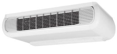
44 Fan coil units Duct Unit FWD TABLE OF CONTENTS FWD Duct Unit FWD 1 Features Specifications Nominal capacity and nominal input Technical Specifications Electrical Specifications Electrical data Options Control systems Capacity tables Cooling capacity tables - 2-pipe / 4-pipe Capacity tables with glycol for process cooling applications Heating capacity tables - 2-pipe Heating capacity tables - 4-pipe Power consumption - 2-pipe / 4-pipe Capacity correction factor Dimensional drawing & centre of gravity Dimensional drawing Wiring diagram Wiring diagram Sound data Sound level data - 2-pipe / 4-pipe Installation Installation method Operation range Hydraulic performance Water pressure drop curve evaporator cooling 2-pipe Water pressure drop curve evaporator heating 2-pipe Water pressure drop curve evaporator heating 4-pipe Hydronic Systems Fan coil units 42

45 Fan coil units Duct Unit FWD Hydronic Systems Fan coil units 4 1 Features 2 1 F a n c o i l u n H y d r o n i c S y s F W D D u c t U n i t Possibility of installation both in horizontal and vertical position Straight duct connector is mounted to discharge side Standard air filter : removable from the bottom
46 2 Specifications Fan coil units Duct Unit FWD 2-1 NOMINAL CAPACITY AND NOMINAL INPUT FWD04AATN FWD06AATN FWD08AATN FWD10AATN FWD012AATN FWD016AATN FWD018AATN Power Input High W Medium W Low W Cooling capacity Total capacity High kw Sensible capacity High kw Heating capacity (2-pipe) High kw NOMINAL CAPACITY AND NOMINAL INPUT FWD04AAFN FWD06AAFN FWD08AAFN FWD10AAFN FWD012AAFN FWD016AAFN FWD018AAFN Power Input High W Medium W Low W Cooling capacity Total capacity High kw Sensible capacity High kw Heating capacity (4-pipe) High kw Hydronic Systems Fan coil units 44
47 2 Specifications Fan coil units Duct Unit FWD TECHNICAL SPECIFICATIONS FWD04AATN FWD06AATN FWD08AATN FWD10AATN FWD012AATN FWD016AATN FWD018AATN Dimensions Unit Height mm Width mm Depth mm Weight Machine weight kg Material Galvanised sheet metal Colour Not painted (galvanised) Sound level Sound power High dba Medium dba Low dba Water flow Cooling l/h Heating l/h Water pressure drop Cooling kpa Heating kpa Fan Type Centrifugal multi-blade, double suction Air flow rate High m³/h Available pressure High Pa Speed steps : high, medium, low Quantity Motor Type Closed induction, B class insulation, winding thermal cut-out Standard heat Rows mm exchanger Stages mm Fin pitch mm Face area m² Water volume l Air filter Acrylic - Filtering class EU2 Insulation material Class 1 self-extinguishing Vibration insulation Rubber ring for fan motor Water connections Std. heat exchanger inch /4 /4 /4 / Drain mm Notes Rating conditions cooling 2 pipe: air 27 Rating conditions heating 2 pipe : air 20 Maximum Power input at 0 Pa ESP Sound level at 0 Pa ESP 45 Hydronic Systems Fan coil units
48 Fan coil units Duct Unit FWD 2 Specifications 2-2 TECHNICAL SPECIFICATIONS FWD04AAFN FWD06AAFN FWD08AAFN FWD10AAFN FWD012AAFN FWD016AAFN FWD018AAFN Dimensions Unit Height mm Width mm Depth mm Weight Machine weight kg Material Galvanised sheet metal Colour Not painted (galvanised) Sound level Sound power High dba Medium dba Low dba Water flow Cooling l/h Heating l/h Water pressure Cooling kpa drop Heating kpa Fan Type Centrifugal multi-blade, double suction Air flow rate High m³/h Available pressure High Pa Speed steps : high, medium, low Quantity Motor Type Closed induction, B class insulation, winding thermal cut-out Standard heat Rows mm exchanger Stages mm Fin pitch mm Face area m² Water volume l Additional heat Rows mm exchanger Stages mm Fin pitch mm Face area m² Water volume l Air filter Acrylic - Filtering class EU2 Insulation material Class 1 self-extinguishing Vibration insulation Rubber ring for fan motor Water Std. heat exchanger inch /4 /4 /4 / connections Drain mm Notes Rating conditions 4-pipe: air 27 CDB - 19 CWB - entering water 7 C - leaving water 12 C at nominal air flow and ESP Rating conditions 4-pipe: air 20 CDB - entering water 70 C - leaving water 60 C at nominal air flow and ESP Maximum Power input at 0 Pa ESP Sound level at 0 Pa ESP 2 2 Hydronic Systems Fan coil units 46
49 2 Specifications Fan coil units Duct Unit FWD 2- ELECTRICAL SPECIFICATIONS FWD04AATN FWD06AATN FWD08AATN FWD10AATN FWD012AATN FWD016AATN FWD018AATN Current input High A Medium A Low A Required power supply V / f / Hz 20/1/50 Required fuses A Required wire section mm² Notes Current input at 0 Pa ESP For more details concerning conditional connections, see select E- data Books. Finally click on the document title of your choice 2 2 FWD04AAF N FWD06AAF N FWD08AAF N FWD10AAF N FWD012AAF N FWD016AAF N FWD018AAF N 2- ELECTRICAL SPECIFICATIONS Current input High A Medium A Low A Required power supply V / f / Hz 20/1/50 Required fuses A Required wire section mm² Notes Current input at 0 Pa ESP For more details concerning conditional connections, see select E- data Books. Finally click on the document title of your choice 47 Hydronic Systems Fan coil units
50 Fan coil units Duct Unit FWD Electrical data FWD Power input electric heater Current Absorption Power supply Unit Electric heater kw A V / /Hz FWD04 EDEHS04A V +- 10% / 1 / 50Hz FWD06 FWD08 FWD10 FWD12 FWD16 FWD18 EDEHS06A EDEHB06A EDEHS10A EDEHB10A EDEHS10A EDEHB10A EDEHS12A EDEHB12A EDEHS18A EDEHB18A EDEHS18A EDEHB18A V +- 10% / / 50Hz 400V +- 10% / / 50Hz 400V +- 10% / / 50Hz 400V +- 10% / / 50Hz 400V +- 10% / / 50Hz 400V +- 10% / / 50Hz 4TW Hydronic Systems Fan coil units 48
51 Fan coil units Duct Unit FWD 4 Options 2 4 FWD Notes/Remarks Electric heater EDEH(S)(B)..A6 EDEH04A6 EDEH(S)(B)06A6 EDEH(S)(B)10A6 EDEH(S)(B)12A6 EDEH(S)(B)18A6 Requires electronic controller 2-pipe ON-OFF way motor driven valve complete with mounting kit 4-pipe ON-OFF way motor driven valve complete with mounting kit ED4MV..A6 ED4MV04A6 ED4MV10A6 Fan stop thermostat YFSTA6 YFSTA6 ED2MV..A6 ED2MV04A6 ED2MV10A6 ED2MV12A6 ED2MV18A6 2x ED2MV12A6 2 x ED2MV18A6 Motorised fresh air intake louvers EDMFA..A6 EDMFA04A6 EDMFA06A6 EDMFA10A6 EDMFA12A6 EDMFA18A6 Controller electronical remote + water probe + power contactor ECFWDER6 ECFWDER6 Auxiliary drain pan (vertical models) EDDPV..A6 EDDPV10A6 EDDPV18A6 For FWD only motor valve (piping not included) For FWD only motor valve (piping not included) 4TW A (Sheet 1/2) FWD Electric heater 2-pipe ON-OFF way motor driven valve complete with mounting kit 4-pipe ON-OFF way motor driven valve complete with mounting kit Fan stop thermostat Motorised fresh air intake louvers Controller electronical remote + water probe + power contactor Auxiliary drain pan (vertical models) EDEH(S)(B)..A6 ED2MV..A6 ED4MV..A6 YFSTA6 EDMFA..A6 ECFWDER6 EDDPV..A6 Electric heater EDEH(S)(B)..A6 X X X X 2-pipe ON-OFF way motor driven valve complete with mounting kit ED2MV..A6 X X X X 4-pipe ON-OFF way motor driven valve complete with mounting kit ED4MV..A6 X X X Fan stop thermostat YFSTA6 X X Motorised fresh air intake louvers EDMFA..A6 X X X X X X Controller electronical remote + water probe + power contactor ECFWDER6 X X X X X Auxiliary drain pan (vertical and horizontal models) EDDPV..A6 X X X X X Auxiliary drain pan (vertical models) EDDPV..A6 X X X X X X 4TW A (Sheet 2/2) 49 Hydronic Systems Fan coil units
52 5 Control systems Fan coil units Duct Unit FWD 4-pipe 2-pipe Cool/heat changeover Options Basic control functions Control features 7 X X X X X X X X X X X X X X X X X X X X X X X X X X X X X X X X X X X X X X X X X X X X X X X X X X X X X X X X X X X X X X X X X 2 5 Manual cool/heat changeover. Automatic cool/heat changeover based on water temperature. Automatic cool/heat changeover based on air temperature. Control of the -way/4pipe ON/OFF valve. The water valve shut-off once the desired temperature is reached. The controller controls the electric heater as integration or replacement of the hot water heating system. When the operating mode selector witch is turned on electric heater and the electric heater is turned on, the fan runs continuously at medium speed. When the operating mode selector switch is turned to electric heater and the electric heater is turned on, the fan runs continuously at medium speed. The fan speed can be set at one of the speeds (low, medium or maximum) by turning the operation mode selector. 7 The fan speed is switched automatically based on the difference between the temperature set on the thermostat and the room temperature. Optimised comfort cooling. When the fan coil has reached the desired setpoint, the fan will operate at medium speed and at regular intervals to ensure constant room temperature and lower sound. The controller prevents the fan coil unit from operating in one mode, if the required water temperature is not achieved to operate in the selected mode. The dead zone is a temperature interval close to the set temperature. When the air is warmer/cooler than the top/lower limit of the neutral zone, the cooling/heating mode is selected. Hydronic Systems Fan coil units 50
53 6 Capacity tables Fan coil units Duct Unit FWD 6-1 Cooling capacity tables - 2-pipe / 4-pipe 2 6 Air temperature ( C DB - C WB) Water temperature (Entering C - leaving C) Water flow Water pressure drop Sensible cooling capacity Total cooling capacity Water flow Water pressure drop Sensible cooling capacity Total cooling capacity Water flow Water pressure drop Sensible cooling capacity Total cooling capacity Water flow Water pressure drop Sensible cooling capacity Model Air flow Total cooling capacity m /h W W!/h kpa W W!/h kpa W W!/h kpa W W!/h kpa FWD FWD FWD FWD FWD FWD FWD TW (Sheet 1/7) 51 Hydronic Systems Fan coil units
54 Fan coil units Duct Unit FWD 6 Capacity tables 6-1 Cooling capacity tables - 2-pipe / 4-pipe Air temperature ( C DB - C WB) Water temperature (Entering C - leaving C) Water flow Water pressure drop Sensible cooling capacity Total cooling capacity Water flow Water pressure drop Sensible cooling capacity Total cooling capacity Water flow Water pressure drop Sensible cooling capacity Total cooling capacity Water flow Water pressure drop Sensible cooling capacity Model Air flow Total cooling capacity m /h W W!/h kpa W W!/h kpa W W!/h kpa W W!/h kpa FWD FWD FWD FWD FWD FWD FWD TW (Sheet 2/7) 2 6 Hydronic Systems Fan coil units 52
55 6 Capacity tables Fan coil units Duct Unit FWD 6-1 Cooling capacity tables - 2-pipe / 4-pipe 2 6 Air temperature ( C DB - C WB) Water temperature (Entering C - leaving C) Water flow Water pressure drop Sensible cooling capacity Total cooling capacity Water flow Water pressure drop Sensible cooling capacity Total cooling capacity Water flow Water pressure drop Sensible cooling capacity Total cooling capacity Water flow Water pressure drop Sensible cooling capacity Model Air flow Total cooling capacity m /h W W!/h kpa W W!/h kpa W W!/h kpa W W!/h kpa FWD FWD FWD FWD FWD FWD FWD TW (Sheet /7) 5 Hydronic Systems Fan coil units
56 6 Capacity tables Fan coil units Duct Unit FWD 6-2 Capacity tables with glycol for process cooling applications Cooling mode Glycol percentage in weight Freezing temperature ( C) Capacity correction factor Pressure drop correction factor Heating mode Glycol percentage in weight Freezing temperature ( C) Capacity correction factor Pressure drop correction factor TW B Correction factors are based on an average value (at rated water flow rate). This can cause deviation depending on conditions used. The Fan Coil Selection software will provide an accurate result at all conditions. Hydronic Systems Fan coil units 54
57 6 Capacity tables Fan coil units Duct Unit FWD 6 - Heating capacity tables - 2-pipe 2 6 Air temperature ( C) 20 Water temperature (Entering C - leaving C) Model Air flow Heating capacity Water flow Water pressure drop Heating capacity Water flow Water pressure drop Heating capacity Water flow Water pressure drop Heating capacity Water flow Water pressure drop m /h W!/h kpa W!/h kpa W!/h kpa W!/h kpa FWD04TN FWD06TN FWD08TN FWD10TN FWD12TN FWD16TN FWD18TN TW (Sheet 4/7) 55 Hydronic Systems Fan coil units
58 Fan coil units Duct Unit FWD 6 Capacity tables 6 - Heating capacity tables - 2-pipe Air temperature ( C) 22 Water temperature (Entering C - leaving C) Model Air flow Heating capacity Water flow Water pressure drop Heating capacity Water flow Water pressure drop Heating capacity Water flow Water pressure drop Heating capacity Water flow Water pressure drop m /h W!/h kpa W!/h kpa W!/h kpa W!/h kpa FWD04TN FWD06TN FWD08TN FWD10TN FWD12TN FWD16TN FWD18TN TW (Sheet 5/7) 2 6 Hydronic Systems Fan coil units 56
59 6 Capacity tables Fan coil units Duct Unit FWD 6-4 Heating capacity tables - 4-pipe 2 6 Air temperature ( C) 20 Water temperature (Entering C - leaving C) Model Air flow Heating capacity Water flow Water pressure drop Heating capacity Water flow Water pressure drop Heating capacity Water flow Water pressure drop Heating capacity Water flow Water pressure drop m /h W!/h kpa W!/h kpa W!/h kpa W!/h kpa FWD04FN FWD06FN FWD08FN FWD10FN FWD12FN FWD16FN FWD18FN TW (Sheet 6/7) 57 Hydronic Systems Fan coil units
60 Fan coil units Duct Unit FWD 6 Capacity tables 6-4 Heating capacity tables - 4-pipe Air temperature ( C) 22 Water temperature (Entering C - leaving C) Model Air flow Heating capacity Water flow Water pressure drop Heating capacity Water flow Water pressure drop Heating capacity Water flow Water pressure drop Heating capacity Water flow Water pressure drop m /h W!/h kpa W!/h kpa W!/h kpa W!/h kpa FWD04FN FWD06FN FWD08FN FWD10FN FWD12FN FWD16FN FWD18TN TW (Sheet 7/7) 2 6 Hydronic Systems Fan coil units 58
61 6 Capacity tables Fan coil units Duct Unit FWD 6-5 Power consumption - 2-pipe / 4-pipe 2 6 FWD04 Max. Med. Min. ESP Power input Current Power input Current Power input Current (Pa) (W) (A) (W) (A) (W) (A) TW ESP: SYMBOLS External static pressure FWD06 Max. Med. Min. ESP Power input Current Power input Current Power input Current (Pa) (W) (A) (W) (A) (W) (A) TW ESP: SYMBOLS External static pressure 59 Hydronic Systems Fan coil units
62 Fan coil units Duct Unit FWD 6 Capacity tables 6-5 Power consumption - 2-pipe / 4-pipe FWD08 Max. Med. Min. ESP Power input Current Power input Current Power input Current (Pa) (W) (A) (W) (A) (W) (A) TW ESP: SYMBOLS External static pressure FWD10 Max. Med. Min. ESP Power input Current Power input Current Power input Current (Pa) (W) (A) (W) (A) (W) (A) TW ESP: SYMBOLS External static pressure Hydronic Systems Fan coil units 60
63 6 Capacity tables Fan coil units Duct Unit FWD 6-5 Power consumption - 2-pipe / 4-pipe 2 6 FWD12 Max. Med. Min. ESP Power input Current Power input Current Power input Current (Pa) (W) (A) (W) (A) (W) (A) TW ESP: SYMBOLS External static pressure 61 Hydronic Systems Fan coil units
64 Fan coil units Duct Unit FWD 6 Capacity tables 6-5 Power consumption - 2-pipe / 4-pipe FWD16 Max. Med. Min. ESP Power input Current Power input Current Power input Current (Pa) (W) (A) (W) (A) (W) (A) TW ESP: SYMBOLS External static pressure Hydronic Systems Fan coil units 62
65 6 Capacity tables Fan coil units Duct Unit FWD 6-5 Power consumption - 2-pipe / 4-pipe 2 6 FWD18 Max. Med. Min. ESP Power input Current Power input Current Power input Current (Pa) (W) (A) (W) (A) (W) (A) TW ESP: SYMBOLS External static pressure 6 Hydronic Systems Fan coil units
66 Fan coil units Duct Unit FWD 6 Capacity tables 6-6 Capacity correction factor ESP (Pa) Fan speed F1 F2 F1 F2 F1 F2 F1 F2 F1 F2 F1 F2 F1 F2 F1 F2 F1 F2 F1 F2 F1 F2 F1 F2 F1 F2 FWD04 Max Med Min FWD06 Max Med Min FWD08 Max Med Min FWD10 Max Med Min FWD12 Max Med Min FWD16 Max Med Min FWD18 Max Med Min TW A Conditions Cooling Air: 27 C DB - 19 C WB - Water: entering 7 C - leaving 12 C F1 = correction factor for air flow Heating 2-pipe Air: 20 C Water: entering 50 C water flow as for cooling F2 = correction factor for capacities Heating 4-pipe Air: 20 C Water: entering 70 C - leaving 60 C The correction factor is applicable also for 4 pipe and heating mode because the differences are negligible. 2 6 Hydronic Systems Fan coil units 64
67 Fan coil units Duct Unit FWD 7 Dimensional drawing & centre of gravity 7-1 Dimensional drawing FWD Legend 1 6 fast-coupling slots 2 Condensate drainage for horizontal installation Condensate drainage for vertical installation 4 Hydraulic connections 4 = standard heat exchanger 4 DF = supplementary heat exchanger 5 Air delivery 6 Air intake 6A = supply terms 6B = changeable during installation 7 Round pre-sheared element (J 100 mm) for fresh air intake Hydraulic connections Standard and additional heat exchanger: connection Male FWD04 FWD06 FWD08 FWD10 FWD12 FWD16 FWD18 /4 /4 /4 / A B C D FWD FWD FWD TW A (Sheet 1/2) 65 Hydronic Systems Fan coil units
68 Fan coil units Duct Unit FWD 7 Dimensional drawing & centre of gravity 7-1 Dimensional drawing FWD Legend 1 6 fast-coupling slots 2 Condensate drainage for horizontal installation Condensate drainage for vertical installation 4 Hydraulic connections 4 = standard heat exchanger 4 DF = supplementary heat exchanger 5 Air delivery 6 Air intake 6A = supply terms 6B = changeable during installation 7 Round pre-sheared element (J 100 mm) for fresh air intake Hydraulic connections Standard and additional heat exchanger: connection Male FWD04 FWD06 FWD08 FWD10 FWD12 FWD16 FWD18 /4 /4 /4 / A B C D FWD FWD TW A (Sheet 2/2) Hydronic Systems Fan coil units 66
69 8 Wiring diagram 8-1 Wiring diagram Fan coil units Duct Unit FWD 2 8 SYMBOLS BK Black = maximum speed BU Blue = medium speed GNYE Yellow/Green = earth connection RD Red = minimum speed WH White = common ---- Field wiring F Protection fuse (field supply) IL Main switch (field supply) M Fan motor PE Earth connection 4TW Hydronic Systems Fan coil units
70 Fan coil units Duct Unit FWD 9 Sound data 9-1 Sound level data - 2-pipe / 4-pipe FWD HZ 250 Hz 500 Hz 1000 Hz 2000 Hz 4000 Hz 8000 Hz Global Lw L w tot db(a) Hz 250 Hz 500 Hz 1000 Hz 2000 Hz 4000 Hz 8000 Hz Max. Outlet Structure Inlet L w tot db(a) Hz 250 Hz 500 Hz 1000 Hz 2000 Hz 4000 Hz 8000 Hz Med. Outlet Structure Inlet L w tot db(a) Hz 250 Hz 500 Hz 1000 Hz 2000 Hz 4000 Hz 8000 Hz Min. Outlet Structure Inlet TW (Sheet 1/7) Sound power levels measured at ESP = 0 Pa 2 9 FWD HZ 250 Hz 500 Hz 1000 Hz 2000 Hz 4000 Hz 8000 Hz Global Lw L w tot db(a) Hz 250 Hz 500 Hz 1000 Hz 2000 Hz 4000 Hz 8000 Hz Max. Outlet Structure Inlet L w tot db(a) Hz 250 Hz 500 Hz 1000 Hz 2000 Hz 4000 Hz 8000 Hz Med. Outlet Structure Inlet L w tot db(a) Hz 250 Hz 500 Hz 1000 Hz 2000 Hz 4000 Hz 8000 Hz Min. Outlet Structure Inlet TW (Sheet 2/7) Sound power levels measured at ESP = 0 Pa Hydronic Systems Fan coil units 68
71 9 Sound data Fan coil units Duct Unit FWD 9-1 Sound level data - 2-pipe / 4-pipe 2 9 FWD HZ 250 Hz 500 Hz 1000 Hz 2000 Hz 4000 Hz 8000 Hz Global Lw L w tot db(a) Hz 250 Hz 500 Hz 1000 Hz 2000 Hz 4000 Hz 8000 Hz Max. Outlet Structure Inlet L w tot db(a) Hz 250 Hz 500 Hz 1000 Hz 2000 Hz 4000 Hz 8000 Hz Med. Outlet Structure Inlet L w tot db(a) Hz 250 Hz 500 Hz 1000 Hz 2000 Hz 4000 Hz 8000 Hz Min. Outlet Structure Inlet TW (Sheet /7) Sound power levels measured at ESP = 0 Pa FWD HZ 250 Hz 500 Hz 1000 Hz 2000 Hz 4000 Hz 8000 Hz Global Lw L w tot db(a) Hz 250 Hz 500 Hz 1000 Hz 2000 Hz 4000 Hz 8000 Hz Max. Outlet Structure Inlet L w tot db(a) Hz 250 Hz 500 Hz 1000 Hz 2000 Hz 4000 Hz 8000 Hz Med. Outlet Structure Inlet L w tot db(a) Hz 250 Hz 500 Hz 1000 Hz 2000 Hz 4000 Hz 8000 Hz Min. Outlet Structure Inlet TW (Sheet 4/7) Sound power levels measured at ESP = 0 Pa 69 Hydronic Systems Fan coil units
72 Fan coil units Duct Unit FWD 9 Sound data 9-1 Sound level data - 2-pipe / 4-pipe FWD HZ 250 Hz 500 Hz 1000 Hz 2000 Hz 4000 Hz 8000 Hz Global Lw L w tot db(a) Hz 250 Hz 500 Hz 1000 Hz 2000 Hz 4000 Hz 8000 Hz Max. Outlet Structure Inlet L w tot db(a) Hz 250 Hz 500 Hz 1000 Hz 2000 Hz 4000 Hz 8000 Hz Med. Outlet Structure Inlet L w tot db(a) Hz 250 Hz 500 Hz 1000 Hz 2000 Hz 4000 Hz 8000 Hz Min. Outlet Structure Inlet TW (Sheet 5/7) Sound power levels measured at ESP = 0 Pa 2 9 FWD HZ 250 Hz 500 Hz 1000 Hz 2000 Hz 4000 Hz 8000 Hz Global Lw L w tot db(a) Hz 250 Hz 500 Hz 1000 Hz 2000 Hz 4000 Hz 8000 Hz Max. Outlet Structure Inlet L w tot db(a) Hz 250 Hz 500 Hz 1000 Hz 2000 Hz 4000 Hz 8000 Hz Med. Outlet Structure Inlet L w tot db(a) Hz 250 Hz 500 Hz 1000 Hz 2000 Hz 4000 Hz 8000 Hz Min. Outlet Structure Inlet TW (Sheet 6/7) Sound power levels measured at ESP = 0 Pa Hydronic Systems Fan coil units 70
73 9 Sound data Fan coil units Duct Unit FWD 9-1 Sound level data - 2-pipe / 4-pipe 2 9 FWD HZ 250 Hz 500 Hz 1000 Hz 2000 Hz 4000 Hz 8000 Hz Global Lw L w tot db(a) Hz 250 Hz 500 Hz 1000 Hz 2000 Hz 4000 Hz 8000 Hz Max. Outlet Structure Inlet L w tot db(a) Hz 250 Hz 500 Hz 1000 Hz 2000 Hz 4000 Hz 8000 Hz Med. Outlet Structure Inlet L w tot db(a) Hz 250 Hz 500 Hz 1000 Hz 2000 Hz 4000 Hz 8000 Hz Min. Outlet Structure Inlet TW (Sheet 7/7) Sound power levels measured at ESP = 0 Pa 71 Hydronic Systems Fan coil units
74 10 Installation 10-1 Installation method Fan coil units Duct Unit FWD BEFORE THE INSTALLATION The equipment is to be installed and serviced exclusively by technical personnel who are qualified for using this type of machine, in compliance with the relevant local and national regulations. On receiving the equipment, check its state ensuring that it was not damaged during transport. Refer to the associated technical sheets for the installation and use instructions of any accessories. INTENDED CONDITIONS OF USE AND OPERATING LIMITS No responsibility is assumed if the equipment is installed by unqualified personnel, if it is used improperly or under inadmissible conditions, if maintenance is not performed as envisaged in this manual or if original spare parts are not used. For the operating limits please refer to the appropriate chapter. Any other use is considered improper. Keep the equipment inside the packing until it is ready to be installed so that dust will not infiltrate. Air sucked by the equipment must always be filtered. Use, when possible, the specific accessories. If not used during the winter, drain the water from the system to prevent damage caused by the formation of ice. If antifreeze solutions are used, check the freezing point. Do not change the internal wiring or other parts of the equipment. INSTALLATION WARNING: On the fan coil unit install a switch (IL) and/or all remote controls in a position out of the reach of persons who are in a bathtub or shower. The FWD units may be installed either in horizontal or vertical position. Check that the desired installation complies with one of the diagrams shown in the installation manual, in which both possible configurations, M or AB, are suitable to work for heating and cooling AA (INTAKE IN LINE - DELIVERY IN LINE) AB (AIR SUCTION AT 90 - AIR OUTLET IN LINE) CONFIGURATION of the unit The units are always supplied in AA configuration, but the air intake position may be changed during the installation. FIXING the unit Fix the standard unit to the ceiling or wall using at least 4 of the 6 slots.; For horizontal insta!!ations (ceiling-mounting) it is advisable to use M8 threaded bars, screw anchors suitable for the machine s weight, and to arrange for the positioning of the machine using 2 M8 bolts and a washer the diameter of which is suitable for Before tightening the check nut, adjust the closing of the main nut so that the equipment will slant correctly, i.e. for facilitating the discharging of the condensate. The correct slant is achieved by tilting the intake downwards as compared to the delivery, until a difference in level of about 10 mm is obtained from one end to the other. Make the hydraulic connections with the heat exchanger and, for cooling operations, with the condensate discharge. Use one of the two drains of the auxiliary tank, visible on the outside of the unit s side panels and vertical condensate discharge. For vertical installations (wall-mounting), fix the unit so that water may flow out toward the condensate discharge used. A slant equivalent to a difference in level of about 5 mm is enough between the two side panels. The two condensate discharge tubes of the main tank are located inside the side panels and may be accessed through a membrane type passage that should be perforateed for passing the discharge tube through it. It is advisable not to remove the aforesaid passage because it prevents the sharp edge of the hole on the side panel from damaging the condensate discharge tube over time. To connect the unit to the condensate discharge line, use a flexible rubber tube and fix it to the chosen discharge tube (f /8) by means of a metal clamp (use the discharge that is located on the hydraulic attachments side). To assist the draining of the condensate, slant the discharge tube downwards by at least 0 mm/m making sure that its entire route is clear and free from bends or blockages. A few rules to follow Carry out the heat exchanger s air exhaust, with pumps stopped, by means of the air valves located adjacent to the attachments of the heat exchanger itself. Hydronic Systems Fan coil units 72
75 10 Installation 10-1 Installation method Fan coil units Duct Unit FWD When implementing a duct system, it is advisable to place the vibration-damping joints between the ducting and the unit. If you wish to install an electrical resistance module as accessory, the delivery vibration-damping joint should be heat-resistant. The ducting, especially the delivery one, should be insulated with anticondensing material. Provide an inspection panel adjacent to the equipment for the maintenance and cleaning operations. Install the control panel on the wall. Choose a position that is easy to access for the setting of the functions and, if contemplated, for the reading of the temperature. Try to avoid positions that are directiy exposed to sun rays, or positions subject to direct hot or cold air currents, and do not place obstacles in the way that would prevent the correct reading of the temperature ELECTRICAL CONNECTIONS Carry out the electrical wiring after having turned the power off in compliance with the relevant local and national regulations following the relevant wiring diagram. Only qualified personnel should carry out the wiring operations. Each fan coil requires a switch (IL) on the feeder line with a distance of at least mm between the opening contacts, and a suitable safety fuse (F). Power consumption is shown on the data plate fixed to the unit. Make sure to carefully execute the wiring in function of the combination unit/controller and this according to the correct wiring diagram delivered with every accessory. In order to make the electrical connections you must remove the lower closing panel to access the terminal board. The power cables (power supply and control) must be routed to the terminal board through the membrane passage that is on the side panel of the machine on the side opposite the hydraulic attachments. WARNING The COMMON wire of the motor is the WHITE one: if connected incorrectiy the motor would be damaged irreparably. FUNCTIONAL CHECKS Check that the equipment has been installed so that it guarantees the required slant. Check that the condensate discharge is not clogged (by rubble deposits, etc.). Check the seal of the hydraulic connections. Check that all the wirings are tight (perform the check with voltage OFF). Make sure air has been purged from the heat exchanger. Power the equipment and check its working efficiency. 7 Hydronic Systems Fan coil units
 - 200 mm free space on the opposite side (to unscrew")
76 10 Installation 10-1 Installation method 1. Ducted unit with filter only Fan coil units Duct Unit FWD Consider at least: mm free space on water connections side (piping & connections) mm free space on the opposite side (to unscrew heat exchangers or fan deck in case of repairing) - Possibility to extract filter for cleaning has to be considered - Possibility to reach the unit for ordinary and extraordinary maintenance (for instance removing front panels) has to be considered TW Hydronic Systems Fan coil units 74
77 10 Installation 10-1 Installation method 2. Ducted unit with filter and electric heater Consider also: Fan coil units Duct Unit FWD mm free space on water connections side (piping & connections), measured from the electrical box of the heating module (refer to option technical leaflet for details - total 620 mm) mm free space on the opposite side (to unscrew heat exchangers or fan deck in case of repairing) - Possibility to extract filter for cleaning has to be considered - Possibility to reach the unit for ordinary and extraordinary maintenance (for instance removing front panels) has to be considered TW Hydronic Systems Fan coil units
78 10 Installation 10-1 Installation method. Ducted unit with filter and valves Fan coil units Duct Unit FWD Consider also: mm free space on water connections side (piping & connections), measured from the valve piping (refer to option technical leaflet for details - total around 720 mm) mm free space on the opposite side (to unscrew heat exchangers or fan deck in case of repairing) - Possibility to extract filter for cleaning has to be considered - Possibility to reach the unit for ordinary and extraordinary maintenance (for instance removing front panels) has to be considered TW Hydronic Systems Fan coil units 76
79 11 Operation range Fan coil units Duct Unit FWD Minimum water temperature Maximum water temperature Maximum operating pressure Minimum air inlet temperature Maximum air inlet temperature Power supply +5 C +95 C 10 bar -20 C +4 C 20V +-10% / 1 / 50Hz 4TW Hydronic Systems Fan coil units
80 Fan coil units Duct Unit FWD 12 Hydraulic performance 12-2 Water pressure drop curve evaporator heating 2-pipe FWD Water flow l/h Water pressure drop FWD04 FWD06 FWD08 FWD10 FWD12 FWD16 FWD18 kpa kpa kpa kpa kpa kpa kpa Water pressure drop curve evaporator heating 2-pipe 4TW (Sheet 1/) FWD Water flow l/h Water pressure drop FWD04 FWD06 FWD08 FWD10 FWD12 FWD16 FWD18 kpa kpa kpa kpa kpa kpa kpa TW (Sheet 2/) 2 12 Hydronic Systems Fan coil units 78
81 Fan coil units Duct Unit FWD 12 Hydraulic performance 12 - Water pressure drop curve evaporator heating 4-pipe 2 12 FWD Water flow l/h Water pressure drop FWD04 FWD06 FWD08 FWD10 FWD12 FWD16 FWD18 kpa kpa kpa kpa kpa kpa kpa TW (Sheet /) 79 Hydronic Systems Fan coil units
82 Fan coil units Small Duct Unit FWB TABLE OF CONTENTS FWB FWB Small Duct Unit 1 Features Specifications Nominal capacity and nominal input Technical Specifications Electrical Specifications Electrical data Options Capacity tables Cooling capacity tables - 2-pipe Capacity tables with glycol for process cooling applications Heating capacity tables - 2-pipe Heating capacity tables additional heat exchanger Power consumption Capacity correction factor Dimensional drawing & centre of gravity Dimensional drawing Wiring diagram Wiring diagram Sound data Sound power spectrum - 2-pipe Installation Installation method Operation range Water pressure drop curve evaporator Water pressure drop curve evaporator cooling 2-pipe Water pressure drop curve evaporator heating 2-pipe Water pressure drop curve evaporator additional heat exchanger Hydronic Systems Fan coil units 80
83 sn yu c l u c i i o n cl o l r na d ay F Fan coil units Small Duct Unit FWB 1 Features t S D B mw HS Height of the units only 240mm for all the sizes, 4 or 6 stage row cooling coil Drain pan to collect the condensate from: heat exchanger and regulating valves 7-speed electrical motors (with thermal protection on windings) All 7 speeds pre-wired in the factory in the terminal block of the switch box Standard air filter : removable from the bottom 1 81 Hydronic Systems Fan coil units
84 Fan coil units Small Duct Unit FWB 2 Specifications 2-1 NOMINAL CAPACITY AND NOMINAL INPUT FWB02AT FWB0AT FWB04AT Power Input High W Medium W Low W Cooling capacity Total capacity High kw Medium kw Low kw Sensible capacity High kw Medium kw Low kw Heating capacity High kw (2-pipe) Medium kw Low kw Heating capacity High kw (4-pipe) Medium kw Low kw NOMINAL CAPACITY AND NOMINAL INPUT FWB05AT FWB06AT FWB07AT Power Input High W Medium W Low W Cooling capacity Total capacity High kw Medium kw Low kw Sensible capacity High kw Medium kw Low kw Heating capacity High kw (2-pipe) Medium kw Low kw Heating capacity High kw (4-pipe) Medium kw Low kw NOMINAL CAPACITY AND NOMINAL INPUT FWB08AT FWB09AT FWB10AT Power Input High W Medium W Low W Cooling capacity Total capacity High kw Medium kw Low kw Sensible capacity High kw Medium kw Low kw Heating capacity High kw (2-pipe) Medium kw Low kw Heating capacity High kw (4-pipe) Medium kw Low kw Hydronic Systems Fan coil units 82
85 2 Specifications Fan coil units Small Duct Unit FWB TECHNICAL SPECIFICATIONS FWB02AT FWB0AT FWB04AT Dimensions Unit Height mm Width mm Depth mm Unit with packing Height mm Width mm Depth mm Weight Machine weight kg Operation weight kg Gross weight kg Material Galvanised sheet metal Sound level Sound pressure High dba Medium dba Low dba Sound power High dba Medium dba Low dba Water flow Cooling l/h Heating l/h Add. heat exchanger l/h Water pressure drop Cooling kpa Heating kpa Add. heat exchanger kpa Fan Type Centrifugal - forward blades - directly coupled on fan Air flow rate High m³/h Medium m³/h Low m³/h Available pressure High Pa Medium Pa Low Pa Speed 7 speeds (high = 7, medium = 4, low = 1) Quantity Motor Type Closed induction, B class insulation, winding thermal cut-out Standard heat Rows mm 4 6 exchanger Stages mm 4 Fin pitch mm Face area m² Water volume l Additional heat Rows mm exchanger Stages mm Fin pitch mm Face area m² Water volume l Air filter Standard filter class EU2 Insulation material Class 1 self-extinguishing Vibration insulation Rubber ring for fan motor Water connections Std. heat exchanger inch /4 Add. heat exchanger inch /4 Drain mm Notes Rating conditions cooling 2 pipe: air 27 Rating conditions heating 2 pipe: air 20 CDB - entering water 70 C - leaving water 60 C Sound power level according to ISO741 - sound pressure calculated at 1.5m distance - Q = 2 8 Hydronic Systems Fan coil units
86 Fan coil units Small Duct Unit FWB 2 Specifications 2-2 TECHNICAL SPECIFICATIONS FWB05AT FWB06AT FWB07AT Dimensions Unit Height mm Width mm Depth mm Unit with packing Height mm Width mm Depth mm Weight Machine weight kg 1 5 Operation weight kg 5 8 Gross weight kg Material Galvanised sheet metal Sound level Sound pressure High dba Medium dba Low dba Sound power High dba Medium dba Low dba Water flow Cooling l/h Heating l/h Add. heat exchanger l/h Water pressure drop Cooling kpa Heating kpa Add. heat exchanger kpa Fan Type Centrifugal - forward blades - directly coupled on fan Air flow rate High m³/h Medium m³/h Low m³/h Available pressure High Pa Medium Pa Low Pa Speed 7 speeds (high = 7, medium = 4, low = 1) Quantity Motor Type Closed induction, B class insulation, winding thermal cut-out Standard heat Rows mm 4 6 exchanger Stages mm Fin pitch mm Face area m² Water volume l Additional heat Rows mm exchanger Stages mm Fin pitch mm Face area m² Water volume l Air filter Standard filter class EU2 Insulation material Class 1 self-extinguishing Vibration insulation Rubber ring for fan motor Water connections Std. heat exchanger inch /4 Add. heat exchanger inch /4 Drain mm Notes Rating conditions cooling 2 pipe: air 27 Rating conditions heating 2 pipe: air 20 CDB - entering water 70 C - leaving water 60 C Sound power level according to ISO741 - sound pressure calculated at 1.5m distance - Q = 2 2 Hydronic Systems Fan coil units 84
87 2 Specifications Fan coil units Small Duct Unit FWB TECHNICAL SPECIFICATIONS FWB08AT FWB09AT FWB10AT Dimensions Unit Height mm Width mm Depth mm Unit with packing Height mm Width mm Depth mm Weight Machine weight kg Operation weight kg Gross weight kg Material Galvanised sheet metal Sound level Sound pressure High dba Medium dba Low dba Sound power High dba Medium dba Low dba Water flow Cooling l/h Heating l/h Add. heat exchanger l/h Water pressure drop Cooling kpa Heating kpa Add. heat exchanger kpa Fan Type Centrifugal - forward blades - directly coupled on fan Air flow rate High m³/h Medium m³/h Low m³/h Available pressure High Pa Medium Pa Low Pa Speed 7 speeds (high = 7, medium = 4, low = 1) Quantity Motor Type Closed induction, B class insulation, winding thermal cut-out Standard heat Rows mm 4 6 exchanger Stages mm Fin pitch mm Face area m² Water volume l Additional heat Rows mm exchanger Stages mm Fin pitch mm Face area m² Water volume l Air filter Standard filter class EU2 Insulation material Class 1 self-extinguishing Vibration insulation Rubber ring for fan motor Water connections Std. heat exchanger inch /4 Add. heat exchanger inch Drain mm Notes Rating conditions cooling 2 pipe: air 27 Rating conditions heating 2 pipe: air 20 CDB - entering water 70 C - leaving water 60 C Sound power level according to ISO741 - sound pressure calculated at 1.5m distance - Q = 2 85 Hydronic Systems Fan coil units
88 2 Specifications Fan coil units Small Duct Unit FWB 2- ELECTRICAL SPECIFICATIONS FWB02AT FWB0AT FWB04AT Current input High A Medium A Low A Required power supply V / f / Hz 20/1/50 Required fuses A Required wire section mm² Electric heater Power input kw Current A Power supply V / f / Hz 20/1/50 Notes The power consumption for the valve motor is 5W (peak) only during opening For more details concerning conditional connections, see select E- data Books. Finally click on the document title of your choice 2- ELECTRICAL SPECIFICATIONS FWB05AT FWB06AT FWB07AT Current input High A Medium A Low A Required power supply V / f / Hz 20/1/50 Required fuses A Required wire section mm² Electric heater Power input kw Current A Power supply V / f / Hz 20/1/50 Notes The power consumption for the valve motor is 5W (peak) only during opening For more details concerning conditional connections, see select E- data Books. Finally click on the document title of your choice 2 2- ELECTRICAL SPECIFICATIONS FWB08AT FWB09AT FWB10AT Current input High A Medium A Low A Required power supply V / f / Hz 20/1/50 Required fuses A Required wire section mm² Electric heater Power input kw Current A Power supply V / f / Hz 20/1/50 Notes The power consumption for the valve motor is 5W (peak) only during opening For more details concerning conditional connections, see select E- data Books. Finally click on the document title of your choice Hydronic Systems Fan coil units 86
89 Electrical data Fan coil units Small Duct Unit FWB FWB Power input electric heater Current Absorption Power supply Unit Electric heater kw A V / f / Hz FWB02AT FWB0AT FWB04AT FWB05AT FWB06AT FWB07AT FWB08AT FWB09AT FWB10AT TW Hydronic Systems Fan coil units
90 Fan coil units Small Duct Unit FWB 4 Options FWB Comments Additional heat exchanger EAH04A6 EAH07A6 EAH10A6 -way valve cooling h/e Factory mounted capacity limitation E2MV07A6 E2MV10A6 2-way valve cooling h/e Factory mounted 2-way valve add. h/e E2MV207A6 E2MC210A6 Electric heater Factory mounted Fan stop thermostat YFSTA6 Power interface - EPIA6 Master / Slave Interface EPIMSA6 * Controller electronic - remote ECFWER6 * In combination with ECFWER6, EPIA6 or EPIMSA6 must be installed for FWB TW A (Sheet 1/2) 4 FWB Additional heat exchanger -way valve add. h/e 2-way valve add. h/e Fan stop thermostat Power interface Master / Slave Interface Controller electronic - remote EAH..A6 E2MV..A6 E2MV2..A6 YFSTA6 EPIA6 EPIMSA6 ECFWER6 Additional heat exchanger EAH..A6 X X X * X X X -way valve add. h/e E2MV..A6 X X X X 2-way valve add. h/e E2MV2..A6 X X X Fan stop thermostat YFSTA6 X * X * Power interface EPIA6 X X X X * X Master / Slave Interface EPIMSA6 X X X Controller electronic - remote ECFWER6 X X X X * = FWB used for heating only 4TW A (Sheet 2/2) Hydronic Systems Fan coil units 88
91 5 Capacity tables Fan coil units Small Duct Unit FWB 5-1 Cooling capacity tables - 2-pipe 5 Air temperature ( C DB - C WB) Water temperature (Entering C - leaving C) Model Air flow Total cooling capacity Sensible cooling capacity Water flow Water pressure drop Total cooling capacity Sensible cooling capacity Water flow Water pressure drop Total cooling capacity Sensible cooling capacity Water flow Water pressure drop Total cooling capacity Sensible cooling capacity Water flow Water pressure drop m /h W W!/h kpa W W!/h kpa W W!/h kpa W W!/h kpa FWB FWB FWB FWB FWB FWB FWB FWB FWB TW (Sheet 1/6) 89 Hydronic Systems Fan coil units
92 Fan coil units Small Duct Unit FWB 5 Capacity tables 5-1 Cooling capacity tables - 2-pipe Air temperature ( C DB - C WB) Water temperature (Entering C - leaving C) Model Air flow Total cooling capacity Sensible cooling capacity Water flow Water pressure drop Total cooling capacity Sensible cooling capacity Water flow Water pressure drop Total cooling capacity Sensible cooling capacity Water flow Water pressure drop Total cooling capacity Sensible cooling capacity Water flow Water pressure drop m /h W W!/h kpa W W!/h kpa W W!/h kpa W W!/h kpa FWB FWB FWB FWB FWB FWB FWB FWB FWB TW (Sheet 2/6) 5 Hydronic Systems Fan coil units 90
93 5 Capacity tables Fan coil units Small Duct Unit FWB 5-2 Capacity tables with glycol for process cooling applications Cooling mode Glycol percentage in weight Freezing temperature ( C) Capacity correction factor Pressure drop correction factor Heating mode Glycol percentage in weight Freezing temperature ( C) Capacity correction factor Pressure drop correction factor TW B Correction factors are based on an average value (at rated water flow rate). This can cause deviation depending on conditions used. The Fan Coil Selection software will provide an accurate result at all conditions. 91 Hydronic Systems Fan coil units
94 Fan coil units Small Duct Unit FWB 5 Capacity tables 5 - Heating capacity tables - 2-pipe Air temperature ( C) 19 Water temperature (Entering C - leaving C) Model Air flow Heating capacity Water flow Water pressure drop Heating capacity Water flow Water pressure drop Heating capacity Water flow Water pressure drop Heating capacity Water flow Water pressure drop m /h W!/h kpa W!/h kpa W!/h kpa W!/h kpa FWB FWB FWB FWB FWB FWB FWB FWB FWB TW (Sheet /6) 5 Hydronic Systems Fan coil units 92
95 5 Capacity tables Fan coil units Small Duct Unit FWB 5 - Heating capacity tables - 2-pipe 5 Air temperature ( C) 20 Water temperature (Entering C - leaving C) Model Air flow Heating capacity Water flow Water pressure drop Heating capacity Water flow Water pressure drop Heating capacity Water flow Water pressure drop Heating capacity Water flow Water pressure drop m /h W!/h kpa W!/h kpa W!/h kpa W!/h kpa FWB FWB FWB FWB FWB FWB FWB FWB FWB TW (Sheet 4/6) 9 Hydronic Systems Fan coil units
96 5 Capacity tables Fan coil units Small Duct Unit FWB 5-4 Heating capacity tables additional heat exchanger Air temperature ( C) 19 Water temperature (Entering C - leaving C) Model Air flow Heating capacity Water flow Water pressure drop Heating capacity Water flow Water pressure drop Heating capacity Water flow Water pressure drop Heating capacity Water flow Water pressure drop m /h W!/h kpa W!/h kpa W!/h kpa W!/h kpa EAH04A EAH07A EAH10A TW (Sheet 5/6) 5 Hydronic Systems Fan coil units 94
97 5 Capacity tables Fan coil units Small Duct Unit FWB 5-4 Heating capacity tables additional heat exchanger 5 Air temperature ( C) 20 Water temperature (Entering C - leaving C) Model Air flow Heating capacity Water flow Water pressure drop Heating capacity Water flow Water pressure drop Heating capacity Water flow Water pressure drop Heating capacity Water flow Water pressure drop m /h W!/h kpa W!/h kpa W!/h kpa W!/h kpa EAH04A EAH07A EAH10A TW (Sheet 6/6) 95 Hydronic Systems Fan coil units
98 5 Capacity tables 5-5 Power consumption FWB02-04 Fan coil units Small Duct Unit FWB Speed 7 (Max.) (Min.) AP Power Current Power Current Power Current Power Current Power Current Power Current Power Current input input input input input input input (Pa) (W) (A) (W) (A) (W) (A) (W) (A) (W) (A) (W) (A) (W) (A) TW (2/4) 5 FWB05-07 Speed 7 (Max.) (Min.) AP Power Current Power Current Power Current Power Current Power Current Power Current Power Current input input input input input input input (Pa) (W) (A) (W) (A) (W) (A) (W) (A) (W) (A) (W) (A) (W) (A) TW (/4) Hydronic Systems Fan coil units 96
99 5 Capacity tables 5-6 Capacity correction factor FWB08-10 Fan coil units Small Duct Unit FWB Speed 7 (Max.) (Min.) AP Power Current Power Current Power Current Power Current Power Current Power Current Power Current input input input input input input input (Pa) (W) (A) (W) (A) (W) (A) (W) (A) (W) (A) (W) (A) (W) (A) TW (4/4) 5 97 Hydronic Systems Fan coil units
100 Fan coil units Small Duct Unit FWB 5 Capacity tables 5-6 Capacity correction factor ESP (Pa) Fan speed F1 F2 F1 F2 F1 F2 F1 F2 F1 F2 F1 F2 F1 F2 F1 F2 F1 F2 FWB02 Min. (1) Med. (4) Max. (7) FWB0 Min. (1) Med. (4) Max. (7) FWB04 Min. (1) Med. (4) Max. (7) FWB05 Min. (1) Med. (4) Max. (7) FWB06 Min. (1) Med. (4) Max. (7) FWB07 Min. (1) Med. (4) Max. (7) FWB08 Min. (1) Med. (4) Max. (7) FWB09 Min. (1) Med. (4) Max. (7) FWB10 Min. (1) Med. (4) Max. (7) TW Conditions Cooling Air: 27 C DB - 19 C WB - Water: entering 7 C - leaving 12 C F1 = correction factor for air flow Heating 2-pipe Air: 20 C Water: entering 50 C water flow as for cooling F2 = correction factor for capacities Correction factors are based on an average value. This can cause deviation depending on conditions used. The Fan Coil Selection software will provide an accurate result at all conditions. 5 Hydronic Systems Fan coil units 98
101 Fan coil units Small Duct Unit FWB 6 Dimensional drawing & centre of gravity 6-1 Dimensional drawing FWB 6 N 2 x /4 Female connections 1 = Water outlet 2 = Water inlet 1x 2x x A B C TW Hydronic Systems Fan coil units
102 7 Wiring diagram 7-1 Wiring diagram Fan coil units Small Duct Unit FWB 7 SYMBOLS BK Black = maximum speed BU Blue = medium speed GNYE Yellow/Green = earth connection RD Red = minimum speed WH White = common ---- Field wiring F Protection fuse (field supply) IL Main switch (field supply) M Fan motor PE Earth connection 4TW Hydronic Systems Fan coil units 100
103 Fan coil units Small Duct Unit FWB 8 Sound data 8-1 Sound power spectrum - 2-pipe 8 FWB Hz 250 Hz 500 Hz 1000 Hz 2000 Hz 4000 Hz 8000 Hz Lw tot db(a) Hz 250 Hz 500 Hz 1000 Hz 2000 Hz 4000 Hz 8000 Hz 7 Outlet Structure Inlet Lw tot db(a) Hz 250 Hz 500 Hz 1000 Hz 2000 Hz 4000 Hz 8000 Hz 6 Outlet Structure Inlet Lw tot db(a) Hz 250 Hz 500 Hz 1000 Hz 2000 Hz 4000 Hz 8000 Hz 5 Outlet Structure Inlet Lw tot db(a) Hz 250 Hz 500 Hz 1000 Hz 2000 Hz 4000 Hz 8000 Hz 4 Outlet Structure Inlet Lw tot db(a) Hz 250 Hz 500 Hz 1000 Hz 2000 Hz 4000 Hz 8000 Hz Outlet Structure Inlet Lw tot db(a) Hz 250 Hz 500 Hz 1000 Hz 2000 Hz 4000 Hz 8000 Hz 2 Outlet Structure nm nm - Inlet Lw tot db(a) Hz 250 Hz 500 Hz 1000 Hz 2000 Hz 4000 Hz 8000 Hz 1 Outlet Structure nm nm - Inlet TW (Sheet 1/) To calculate the sound pressure you must define some conditions and use this formula 4π xd2 L p =L w -10xLog 10 ( Q ) Where: Q = direction factor: is Q=4 if the FCU is installed near 2 walls (vertical or floor-ceiling), Q=2 if the FCU is installed near 1 wall (at floor or ceiling but faraway the 2nd wall) d = distance (mt) from the sound source and the measure point LP = Sound pressure (dba) Lw = Sound power (dba) Conditions of measurements ISO741 = The sound power is calculated WITHOUT any additional inlet or outlet grill or plenum. nm = Not measurable 101 Hydronic Systems Fan coil units
104 Fan coil units Small Duct Unit FWB 8 Sound data 8-1 Sound power spectrum - 2-pipe FWB Hz 250 Hz 500 Hz 1000 Hz 2000 Hz 4000 Hz 8000 Hz Lw tot db(a) Hz 250 Hz 500 Hz 1000 Hz 2000 Hz 4000 Hz 8000 Hz 7 Outlet Structure Inlet Lw tot db(a) Hz 250 Hz 500 Hz 1000 Hz 2000 Hz 4000 Hz 8000 Hz 6 Outlet Structure Inlet Lw tot db(a) Hz 250 Hz 500 Hz 1000 Hz 2000 Hz 4000 Hz 8000 Hz 5 Outlet Structure Inlet Lw tot db(a) Hz 250 Hz 500 Hz 1000 Hz 2000 Hz 4000 Hz 8000 Hz 4 Outlet Structure Inlet Lw tot db(a) Hz 250 Hz 500 Hz 1000 Hz 2000 Hz 4000 Hz 8000 Hz Outlet Structure nm - Inlet Lw tot db(a) Hz 250 Hz 500 Hz 1000 Hz 2000 Hz 4000 Hz 8000 Hz 2 Outlet Structure nm nm - Inlet Lw tot db(a) Hz 250 Hz 500 Hz 1000 Hz 2000 Hz 4000 Hz 8000 Hz 1 Outlet Structure nm nm - Inlet TW (Sheet 2/) 8 To calculate the sound pressure you must define some conditions and use this formula 4π xd2 L p =L w -10xLog 10 ( Q ) Where: Q = direction factor: is Q=4 if the FCU is installed near 2 walls (vertical or floor-ceiling), Q=2 if the FCU is installed near 1 wall (at floor or ceiling but faraway the 2nd wall) d = distance (mt) from the sound source and the measure point LP = Sound pressure (dba) Lw = Sound power (dba) Conditions of measurements ISO741 = The sound power is calculated WITHOUT any additional inlet or outlet grill or plenum. nm = Not measurable Hydronic Systems Fan coil units 102
105 Fan coil units Small Duct Unit FWB 8 Sound data 8-1 Sound power spectrum - 2-pipe 8 FWB Hz 250 Hz 500 Hz 1000 Hz 2000 Hz 4000 Hz 8000 Hz Lw tot db(a) Hz 250 Hz 500 Hz 1000 Hz 2000 Hz 4000 Hz 8000 Hz 7 Outlet Structure Inlet Lw tot db(a) Hz 250 Hz 500 Hz 1000 Hz 2000 Hz 4000 Hz 8000 Hz 6 Outlet Structure Inlet Lw tot db(a) Hz 250 Hz 500 Hz 1000 Hz 2000 Hz 4000 Hz 8000 Hz 5 Outlet Structure Inlet Lw tot db(a) Hz 250 Hz 500 Hz 1000 Hz 2000 Hz 4000 Hz 8000 Hz 4 Outlet Structure Inlet Lw tot db(a) Hz 250 Hz 500 Hz 1000 Hz 2000 Hz 4000 Hz 8000 Hz Outlet Structure Inlet Lw tot db(a) Hz 250 Hz 500 Hz 1000 Hz 2000 Hz 4000 Hz 8000 Hz 2 Outlet Structure Inlet Lw tot db(a) Hz 250 Hz 500 Hz 1000 Hz 2000 Hz 4000 Hz 8000 Hz 1 Outlet Structure Inlet TW (Sheet /) To calculate the sound pressure you must define some conditions and use this formula 4π xd2 L p =L w -10xLog 10 ( Q ) Where: Q = direction factor: is Q=4 if the FCU is installed near 2 walls (vertical or floor-ceiling), Q=2 if the FCU is installed near 1 wall (at floor or ceiling but faraway the 2nd wall) d = distance (mt) from the sound source and the measure point LP = Sound pressure (dba) Lw = Sound power (dba) Conditions of measurements ISO741 = The sound power is calculated WITHOUT any additional inlet or outlet grill or plenum. nm = Not measurable 10 Hydronic Systems Fan coil units
106 9 Installation 9-1 Installation method Fan coil units Small Duct Unit FWB BEFORE THE INSTALLATION The equipment is to be installed and serviced exclusively by technical personnel who are qualified for using this type of machine, in compliance with the relevant local and national regulations. On receiving the equipment, check its state ensuring that it was not damaged during transport. Refer to the associated technical sheets for the installation and use instructions of any accessories. INTENDED CONDITIONS OF USE AND OPERATING LIMITS No responsibility is assumed if the equipment is installed by unqualified personnel, if it is used improperly or under inadmissible conditions, if maintenance is not performed as envisaged in this manual or if original spare parts are not used. For the operating limits please refer to the appropriate chapter. Any other use is considered improper. Keep the equipment inside the packing until it is ready to be installed so that dust will not infiltrate. Air sucked by the equipment must always be filtered. Use, when possible, the specific accessories. If not used during the winter, drain the water from the system to prevent damage caused by the formation of ice. If antifreeze solutions are used, check the freezing point. Do not change the internal wiring or other parts of the equipment. INSTALLATION WARNING: On the thermal-ventilating unit install a switch (IL) and/or all remote controls in a position out of the reach of persons who are in a bathtub or shower. The FWB units may be installed only in horizontal position. Check that the desired installation complies with one of the diagrams shown in the installation manual. 9 FIXING the unit Fix the standard unit to the ceiling or wall using at least 4 of the 6 slots.; For the installation (ceiling-mounting) it is advisable to use M8 threaded bars, screw anchors suitable for the machine s weight, and to arrange for the positioning of the machine using 2 M8 bolts and a washer the diameter of which is suitable for inserting the slot and for then fixing the unit. Before tightening the check nut, adjust the closing of the main nut so that the equipment will slant correctly, i.e. for facilitating the discharging of the condensate. The correct slant is achieved by tilting the intake downwards as compared to the delivery, until a difference in level of about 10 mm is obtained from one end to the other. Make the hydraulic connections with the heat exchanger and, for cooling operations, with the condensate discharge. Use one of the two drains of the auxiliary tank, visible on the outside of the unit s side panels and vertical condensate discharge. 4TW (Sheet 1/2) Hydronic Systems Fan coil units 104
107 9 Installation 9-1 Installation method Fan coil units Small Duct Unit FWB A few rules to follow Carry out the heat exchanger s air exhaust, with pumps stopped, by means of the air valves located adjacent to the attachments of the heat exchanger itself. When implementing a duct system, it is advisable to place the vibration-damping joints between the ducting and the unit. If you wish to install an electrical resistance module as accessory, the delivery vibration-damping joint should be heat-resistant. The ducting, especially the delivery one, should be insulated with anticondensing material. Provide an inspection panel adjacent to the equipment for the maintenance and cleaning operations. Install the control panel on the wall. Choose a position that is easy to access for the setting of the functions and, if contemplated, for the reading of the temperature. Try to avoid positions that are directiy exposed to sun rays, or positions subject to direct hot or cold air currents, and do not place obstacles in the way that would prevent the correct reading of the temperature. 9 ELECTRICAL CONNECTIONS Make the electrical connections with voltage OFF, in compliance with the relevant local and national regulations. Exclusively qualified personnel should carry out the wiring operations. Each fancoil unit requires a switch (IL) on the feeder line with a distance of at least mm between the opening contacts, and a suitable safety fuse (F). Power consumption is shown on the data plate fixed to the unit. Make sure to carefully execute the wiring in function of the combination unit/controller and this according to the correct wiring diagram delivered with every accessory. In order to make the electrical connections you must remove the lower closing panel to access the terminal board. The power cables (power supply and control) must be routed to the terminal board through the cable grip that is on the side panel of the machine on the same side of the hydraulic connections. WARNING The COMMON wire of the motor is the WHITE one: if connected incorrectiy the motor would be damaged irreparably. See wiring diagrams for color codes. FUNCTIONAL CHECKS Check that the equipment has been installed so that it guarantees the required slant. Check that the condensate discharge is not clogged (by rubble deposits, etc.). Check the seal of the hydraulic connections. Check that all the wirings are tight (perform the check with voltage OFF). Make sure air has been purged from the heat exchanger. Power the equipment and check its working efficiency. Installation & service distances for FWB units Consider at least 500 mm free space on water connections side (piping & connections) measured from the boundary of the drain pan. 200 mm free space on the opposite side (to unscrew heat exchangers or fan deck in case of repairing) Possibility to extract filter for cleaning has to be considered Possibility to reach the unit for ordinary and extraordinary maintenance (for instance removing front panels) has to be considered 4TW (Sheet 2/4) 105 Hydronic Systems Fan coil units
108 10 Operation range Fan coil units Small Duct Unit FWB Minimum water temperature +5 C Maximum water temperature +95 C Maximum operating pressure 10 bar Minimum air inlet temperature 5 C Maximum air inlet temperature +4 C Power supply 20V +-10% / 1 / 50Hz 4TW Hydronic Systems Fan coil units 106
109 Fan coil units Small Duct Unit FWB 11 Water pressure drop curve evaporator 11-2 Water pressure drop curve evaporator heating 2-pipe 11 Water flow l/h FWB Water pressure drop FWB02 FWB0 FWB04 FWB05 FWB06 FWB07 FWB08 FWB09 FWB10 kpa kpa kpa kpa kpa kpa kpa kpa kpa <1 <1 <1 <1 <1 <1 < < TW (Sheet 1/) 12-2 Water pressure drop curve evaporator heating 2-pipe Water flow l/h FWB Water pressure drop FWB02 FWB0 FWB04 FWB05 FWB06 FWB07 FWB08 FWB09 FWB10 kpa kpa kpa kpa kpa kpa kpa kpa kpa 100 <1 1 <1 <1 <1 <1 <1 <1 < < < TW (Sheet 2/) 107 Hydronic Systems Fan coil units
110 Fan coil units Small Duct Unit FWB 11 Water pressure drop curve evaporator 11 - Water pressure drop curve evaporator additional heat exchanger Water flow l/h FWB Water pressure drop EAH04A6 EAH07A6 EAH10A6 kpa kpa kpa <1 < < TW (Sheet /) 11 Hydronic Systems Fan coil units 108
111
112 Fan coil units Ceiling mounted cassette unit FWC TABLE OF CONTENTS FWC FWC Ceiling mounted cassette unit 1 Features Specifications Nominal capacity and nominal input Technical Specifications Electrical Specifications Control systems Capacity tables Cooling capacity tables Capacity tables with glycol for process cooling applications Heating capacity tables Capacity correction factor Dimensional drawing & centre of gravity Dimensional drawing Piping diagram Wiring diagram Wiring diagram Sound data Sound power spectrum Operation range Hydraulic performance Water pressure drop curve evaporator Hydronic Systems Fan coil units 110
 speed fan motor Double-intake centrifugal fans 4 way air discharge and air swing Air suction from underneath High power air flow Slim front panel and aesthetic design")
113 sn y u l c i i o n c o r n d ay F Fan coil units Ceiling mounted cassette unit FWC 1 Features n S C W H Wide operating range Quiet operation with auto-swing comfort Easy to install and maintain Flexibility (2-pipe or 4-pipe) speed fan motor Double-intake centrifugal fans 4 way air discharge and air swing Air suction from underneath High power air flow Slim front panel and aesthetic design Removable washable air filter (self-extinguishing class 1) Built-in high pressure drain pump (up to 700mm condensate water can be pumped) Wireless controller as standard with decoration panel kit Hydronic Systems Fan coil units
114 2 Specifications Fan coil units Ceiling mounted cassette unit FWC 2-1 NOMINAL CAPACITY AND NOMINAL INPUT FWC02AF FWC0AF FWC04AF FWC05AF FWC06AF FWC07AT FWC08AT FWC10AT Power Input High W Medium W Low W Cooling capacity Total capacity High kw Medium kw Low kw Sensible capacity High kw Medium kw Low kw Heating capacity (2- High kw pipe) Medium kw Low kw Heating capacity (4- High kw pipe) Medium kw Low kw NOMINAL CAPACITY AND NOMINAL INPUT FWC11AT FWC12AT Power Input High W Medium W Low W Cooling capacity Total capacity High kw Medium kw Low kw Sensible capacity High kw Medium kw Low kw Heating capacity (2- High kw pipe) Medium kw Low kw TECHNICAL SPECIFICATIONS FWC02AF FWC0AF FWC04AF FWC05AF FWC06AF FWC07AT FWC08AT FWC10AT Dimensions Unit Height mm Width mm Depth mm Unit with packing Height mm Width mm Depth mm Weight Machine weight kg Operation weight kg Gross weight kg Material Electro-galvanised mild steel (ABS) Sound level Sound pressure High dba Medium dba Low dba Sound power High dba Medium dba Low dba Water flow Cooling l/h ,140 1,290 1,514 Heating l/h 1,140 1,290 1,514 Add. heat exchanger l/h ,076 1,159 1,184 Water pressure drop Cooling kpa Heating kpa Add. heat exchanger kpa Hydronic Systems Fan coil units 112
115 2 Specifications Fan coil units Ceiling mounted cassette unit FWC TECHNICAL SPECIFICATIONS FWC02AF FWC0AF FWC04AF FWC05AF FWC06AF FWC07AT FWC08AT FWC10AT Fan Type Direct drive turbo fan Air flow rate High m³/h 1,10 1,80 1,560 1,740 1,840 1,10 1,80 1,560 Medium m³/h 1,10 1,180 1,20 1,50 1,680 1,10 1,180 1,20 Low m³/h 1,070 1,070 1,210 1,40 1,540 1,070 1,070 1,210 Speed steps : high, medium, low Quantity Motor Type Induction Standard heat Rows mm exchanger Stages mm Fin pitch mm Face area m² Water volume l Air filter Washable Sarannet Insulation material PE Vibration insulation Rubber Bush (Fan Motor) Water connections Std. heat exchanger inch /4 Add. heat exchanger inch /4 /4 /4 /4 /4 Drain mm Notes Rating conditions cooling 2 pipe: air 27 Rating conditions heating 2 pipe : air 20 Sound power level according to ISO741 Sound pressure measured at 1 m in front of the unit and 0.8 m below the vertical centre line of the unit. (JIS C 9612) Sound pressure measured at 1,4m below the facia (JIS C 9612) Sound pressure measured at 1,5m below the facia (JIS B 8615) Rating conditions heating 4 pipe : air TECHNICAL SPECIFICATIONS FWC11AT FWC12AT Dimensions Unit Height mm 5 5 Width mm Depth mm Unit with Height mm packing Width mm Depth mm Weight Machine weight kg Operation weight kg Gross weight kg Material Electro-galvanised mild steel (ABS) Sound level Sound High dba 51 5 pressure Medium dba Low dba Sound power High dba Medium dba 59 6 Low dba Water flow Cooling l/h 1,711 1,858 Heating l/h 1,711 1,858 Water pressure Cooling kpa drop Heating kpa Fan Type Direct drive turbo fan Air flow rate High m³/h 1,740 1,840 Medium m³/h 1,50 1,680 Low m³/h 1,40 1,540 Speed steps : high, medium, low Quantity 1 1 Motor Type Induction 11 Hydronic Systems Fan coil units
116 Fan coil units Ceiling mounted cassette unit FWC 2 Specifications 2-2 TECHNICAL SPECIFICATIONS FWC11AT FWC12AT Standard heat Rows mm 2 2 exchanger Stages mm 4 4 Fin pitch mm Face area m² Water volume l Air filter Washable Sarannet Insulation material PE Vibration insulation Rubber Bush (Fan Motor) Water connections Std. heat exchanger inch /4 Drain mm Notes Rating conditions cooling 2 pipe: air 27 Rating conditions heating 2 pipe : air 20 Sound power level according to ISO741 Sound pressure measured at 1 m in front of the unit and 0.8 m below the vertical centre line of the unit. (JIS C 9612) Sound pressure measured at 1,4m below the facia (JIS C 9612) Sound pressure measured at 1,5m below the facia (JIS B 8615) Rating conditions heating 4 pipe : air ELECTRICAL SPECIFICATIONS FWC02AF FWC0AF FWC04AF FWC05AF FWC06AF FWC07AT FWC08AT FWC10AT Current input High A Medium A Low A Required power supply V / f / Hz / 1 / 50 Required fuses A Required wire section mm² ELECTRICAL SPECIFICATIONS FWC11AT FWC12AT Current input High A Medium A Low A Required power supply V / f / Hz / 1 / 50 Required fuses A 2 2 Required wire section mm² Hydronic Systems Fan coil units 114
117 Control systems Fan coil units Ceiling mounted cassette unit FWC Control systems for FWC-FWF-FWT Controller Application Manual Automatic WRC SRC MERCA Operation mode Basic Controls Energy saving mode Timer setting Air distribution Faster cooling/heating Temperature setting Operation mode: -Cooling only: Cool, Dry and Fan -Heating mode: Auto, Cool, Dry, Fan and Heat -Automode is only available for 4-pipe applications Automatic Fan Speed Fan speed: high/medium/low Sleep mode ON/OFF Automatic air swing Turbo 2-pipe x x x x x x option x 4-pipe x x x x x x x option x 2-pipe x x x x x x option 4-pipe x x x x x x x x 2-pipe x x x x x x x 4-pipe x x x x x x x x 4 Temperature Setting: To set the desired room temperature Fan speed: high, medium, low or automatic Sleep Mode: energy saving option while optimising comfort conditions by temperature adjustment Timer setting: to turn ON/OFF the air conditioner at the desired time Automatic air swing: air distribution according to a specific direction 115 Hydronic Systems Fan coil units
118 4 Capacity tables 4-1 Cooling capacity tables Fan coil units Ceiling mounted cassette unit FWC Cooling capacities FWC-F (4 pipe) Air temperature ( C DB - C WB) Water temperature (Entering C - Leaving C) Total Sensible Water Total Sensible Water Total Sensible Water Total Sensible Model Air Flow cooling cooling Water pressure cooling cooling Water pressure cooling cooling Water pressure cooling cooling capacity capacity flow drop capacity capacity flow drop capacity capacity flow drop capacity capacity kw kw m /hr kpa kw kw m /hr kpa kw kw m /hr kpa kw kw FWC02AF High Medium Low FWC0AF High Medium Low FWC04AF High Medium Low FWC05AF High Medium Low FWC06AF High Medium Low Water flow m /hr Water pressure drop kpa Air temperature ( C DB - C WB) Water temperature (Entering C - Leaving C) Total Sensible Water Total Sensible Water Total Sensible Water Total Sensible Model Air Flow cooling cooling Water pressure cooling cooling Water pressure cooling cooling Water pressure cooling cooling capacity capacity flow drop capacity capacity flow drop capacity capacity flow drop capacity capacity kw kw m /hr kpa kw kw m /hr kpa kw kw m /hr kpa kw kw FWC02AF High Medium Low FWC0AF High Medium Low FWC04AF High Medium Low FWC05AF High Medium Low FWC06AF High Medium Low Water flow m /hr Water pressure drop kpa 4 4 Air temperature ( C DB - C WB) Water temperature (Entering C - Leaving C) Total Sensible Water Total Sensible Water Total Sensible Water Total Sensible Model Air Flow cooling cooling Water pressure cooling cooling Water pressure cooling cooling Water pressure cooling cooling Water capacity capacity flow drop capacity capacity flow drop capacity capacity flow drop capacity capacity flow kw kw m /hr kpa kw kw m /hr kpa kw kw m /hr kpa kw kw m /hr FWC02AF High Medium Low FWC0AF High Medium Low FWC04AF High Medium Low FWC05AF High Medium Low FWC06AF High Medium Low Air temperature ( C DB - C WB) 0-22 Water temperature (Entering C - Leaving C) Total Sensible Water Total Sensible Water Total Sensible Water Total Sensible Model Air Flow cooling cooling Water pressure cooling cooling Water pressure cooling cooling Water pressure cooling cooling Water capacity capacity flow drop capacity capacity flow drop capacity capacity flow drop capacity capacity flow kw kw m /hr kpa kw kw m /hr kpa kw kw m /hr kpa kw kw m /hr FWC02AF High Medium Low FWC0AF High Medium Low FWC04AF High Medium Low FWC05AF High Medium Low FWC06AF High Medium Low Water pressure drop kpa Water pressure drop kpa Hydronic Systems Fan coil units 116
119 4 Capacity tables 4-1 Cooling capacity tables Fan coil units Ceiling mounted cassette unit FWC Cooling capacities FWC-T (2 pipe) Air temperature ( C DB - C WB) Water temperature (Entering C - Leaving C) Total Sensible Water Total Sensible Water Total Sensible Water Total Sensible Model Air Flow cooling cooling Water pressure cooling cooling Water pressure cooling cooling Water pressure cooling cooling capacity capacity flow drop capacity capacity flow drop capacity capacity flow drop capacity capacity kw kw m /hr kpa kw kw m /hr kpa kw kw m /hr kpa kw kw FWC07AT High Medium Low FWC08AT High Medium Low FWC10AT High Medium Low FWC11AT High Medium Low FWC12AT High Medium Low Water flow m /hr Water pressure drop kpa 4 4 Air temperature ( C DB - C WB) Water temperature (Entering C - Leaving C) Total Sensible Water Total Sensible Water Total Sensible Water Total Sensible Model Air Flow cooling cooling Water pressure cooling cooling Water pressure cooling cooling Water pressure cooling cooling capacity capacity flow drop capacity capacity flow drop capacity capacity flow drop capacity capacity kw kw m /hr kpa kw kw m /hr kpa kw kw m /hr kpa kw kw FWC07AT High Medium Low FWC08AT High Medium Low FWC10AT High Medium Low FWC11AT High Medium Low FWC12AT High Medium Low Water flow m /hr Water pressure drop kpa Air temperature ( C DB - C WB) Water temperature (Entering C - Leaving C) Total Sensible Water Total Sensible Water Total Sensible Water Total Sensible Model Air Flow cooling cooling Water pressure cooling cooling Water pressure cooling cooling Water pressure cooling cooling Water capacity capacity flow drop capacity capacity flow drop capacity capacity flow drop capacity capacity flow kw kw m /hr kpa kw kw m /hr kpa kw kw m /hr kpa kw kw m /hr FWC07AT High Medium Low FWC08AT High Medium Low FWC10AT High Medium Low FWC11AT High Medium Low FWC12AT High Medium Low Air temperature ( C DB - C WB) 0-22 Water temperature (Entering C - Leaving C) Total Sensible Water Total Sensible Water Total Sensible Water Total Sensible Water Model Air Flow cooling cooling Water pressure cooling cooling Water pressure cooling cooling Water pressure cooling cooling Water pressure capacity capacity flow drop capacity capacity flow drop capacity capacity flow drop capacity capacity flow drop kw kw m /hr kpa kw kw m /hr kpa kw kw m /hr kpa kw kw m /hr kpa FWC07AT High Medium Low FWC08AT High Medium Low FWC10AT High Medium Low FWC11AT High Medium Low FWC12AT High Medium Low Water pressure drop kpa 117 Hydronic Systems Fan coil units
120 Fan coil units Ceiling mounted cassette unit FWC 4 Capacity tables 4-2 Capacity tables with glycol for process cooling applications Glycol correction factor FWC-F Cooling capacity Entering water temperature C Pressure Drop 0% % % % % Glycol correction factor FWC-T Cooling capacity Entering water temperature C Pressure Drop 0% % % % % Hydronic Systems Fan coil units 118
121 4 Capacity tables 4 - Heating capacity tables Fan coil units Ceiling mounted cassette unit FWC Heating capacities FWC-F (4 pipe) Air temperature ( C DB - C WB) 20 Water temperature (Entering C - Leaving C) Water Water Model Air Flow Heating Water pressure Heating Water pressure Heating Water m /hr capacity flow drop capacity flow drop capacity flow kw m /hr kpa kw m /hr kpa kw m /hr Water pressure drop kpa FWC02AF High Medium Low FWC0AF High Medium Low FWC04AF High Medium Low FWC05AF High Medium Low FWC06AF High Medium Low Air temperature ( C DB - C WB) 22 Water temperature (Entering C - Leaving C) Water Water Model Air Flow Heating Water pressure Heating Water pressure Heating Water m /hr capacity flow drop capacity flow drop capacity flow kw m /hr kpa kw m /hr kpa kw m /hr Water pressure drop kpa FWC02AF High Medium Low FWC0AF High Medium Low FWC04AF High Medium Low FWC05AF High Medium Low FWC06AF High Medium Low Hydronic Systems Fan coil units
122 4 Capacity tables 4 - Heating capacity tables Fan coil units Ceiling mounted cassette unit FWC Heating capacities FWC-T (2 pipe) Air temperature ( C DB - C WB) 20 Water temperature (Entering C - Leaving C) Water Water Model Air Flow Heating Water pressure Heating Water pressure Heating Water capacity flow drop capacity flow drop capacity flow kw m /hr kpa kw m /hr kpa kw m /hr Water pressure drop kpa FWC07AT High Medium Low FWC08AT High Medium Low FWC10AT High Medium Low FWC11AT High Medium Low FWC12AT High Medium Low Air temperature ( C DB - C WB) 22 Water temperature (Entering C - Leaving C) Water Water Model Air Flow Heating Water pressure Heating Water pressure Heating Water capacity flow drop capacity flow drop capacity flow kw m /hr kpa kw m /hr kpa kw m /hr Water pressure drop kpa FWC07AT High Medium Low FWC08AT High Medium Low FWC10AT High Medium Low FWC11AT High Medium Low FWC12AT High Medium Low Hydronic Systems Fan coil units 120
123 4 Capacity tables 4-4 Capacity correction factor Heating correction factor Fan coil units Ceiling mounted cassette unit FWC FWC-F Entering Air temperature Entering Water temperature C C Heating correction factor FWC07T Entering Air temperature Entering Water temperature C C Hydronic Systems Fan coil units
124 Fan coil units Ceiling mounted cassette unit FWC 4 Capacity tables 4-4 Capacity correction factor Heating correction factor FWC08T Entering Air temperature Entering Water temperature C C Heating correction factor Entering Air temperature C FWC10T Entering Water temperature C Hydronic Systems Fan coil units 122
125 4 Capacity tables 4-4 Capacity correction factor Heating correction factor Entering Air temperature C Fan coil units Ceiling mounted cassette unit FWC FWC11T Entering Water temperature C Heating correction factor Entering Air temperature C FWC12T Entering Water temperature C Hydronic Systems Fan coil units
 Model A B C D E F G H I J K FWC02AAFNMV1 820 820 6 5 28 90 90 642 622 555 555 FWC0AAFNMV1 820 820 6 5 28 90 90 642 622 555 555")

126 Fan coil units Ceiling mounted cassette unit FWC 5 Dimensional drawing & centre of gravity 5-1 Dimensional drawing FWC-F B C D E F H A J I G K All dimensions are in (mm) Model A B C D E F G H I J K FWC02AAFNMV FWC0AAFNMV FWC04AAFNMV FWC05AAFNMV FWC06AAFNMV FWC-T SEE DETAIL A 555 WATER OUTLET DETAIL A WATER INLET All dimensions are in mm. Hydronic Systems Fan coil units 124
127 6 Piping diagram Fan coil units Ceiling mounted cassette unit FWC FWC-F (Water piping diagram) Gate Valve Way Valve Gate Valve 2 Way Valve Gate Valve Chiller FCU FCU FCU Gate Valve Gate Valve Gate Valve 4 6 Good Control Bad Control Worst Control FWC-T (Water piping diagram) Gate Valve Way Valve Gate Valve 2 Way Valve Gate Valve Chiller FCU FCU FCU Gate Valve Gate Valve Gate Valve Good Control Bad Control Worst Control 125 Hydronic Systems Fan coil units
128 7 Wiring diagram 7-1 Wiring diagram Fan coil units Ceiling mounted cassette unit FWC FWC-F FCU 1 FCU 2 FCU PART NO: HVLVCVLV L/L1 N/L2 N/L2 HVLV CVLV L/L1 N/L2 N/L2 HVLV CVLV L/L1 N/L2 N/L2 WV WV WV WV WV WV R S T N X1 X2 X CHILLER WV = WAY VALVE X1,X2,X = RELAY ( V,10A) Note This is a proposed wiring connection. It may change subject to the chiller unit and must comply with local and national code an regulations. 4 7 FWC-F HEAT COIL SENSOR COLD COIL SENSOR RETURN AIR SENSOR G/Y DRAIN PUMP PART NO: WIRED CONTROLLER LED/IR RECEIVER BLUE BLUE LEVEL SWITCH POWER SUPPLY BLACK AUX. CONTACT RED AIR SWING MOTOR BLACK G/Y FIELD SUPPLY WIRING WITH JUMPER FOR HEAT PUMP WITHOUT JUMPER FOR COOLING WITH JUMPER FOR VALVE APPLICATION WITHOUT JUMPER FOR VALVELESS APPLICATION WHITE PURPLE HVLV CVLV L/L1 N/L2 N/L2 TO WAY VALVE TO WAY VALVE RED G/Y G/Y RED BLACK Note: Unit comes in standard heatpump and for valve application. L N 220~240V E 1PHASE 50Hz BLACK WHITE RED A.C N BROWN (FL) ORANGE (FM) M.C PURPLE (FH) L.C FAN MOTOR HTR G/Y Hydronic Systems Fan coil units 126
129 PUR PL E (FH) R E D OR A NGE (FM) BROWN (FL ) WHIT E B L A CK PUR PL E R E D B L UE B L UE GR E E N/Y E L L OW 7 Wiring diagram 7-1 Wiring diagram FWC-T Fan coil units Ceiling mounted cassette unit FWC VALVE L FCU 1 N FCU 2 FCU VALVE L N VALVE L N WV WV WV x1 x2 x R S T N 4 7 Chiller WV way valve X1,X2,X Relay ( V,10A) This is proposed wiring connection. It may change subject to the chiller unit and must comply with the local and national code and regulations. FWC-T LED/IR RECEIVER (PRINTED CIRCUIT BOARD) 10 IR.RCV WIRED CONTROLLER 9 LCD WIRELESS CONTROLLER 16 THERMIISTOR COIL SENSOR R E D A.C L.C B L A CK R E D LEVEL SWITCH B L A CK GREEN/YELLOW M.C FAN MOTOR AIR SWING MOTOR CAUTION! VALVE L N GR E E N/Y E L L OW DRAIN PUMP GR E E N/Y E L L OW FIELD SUPPLY WIRING WITH JUMPER FOR HEAT PUMP WITHOUT JUMPER FOR COOLING WITH JUMPER FOR VALVE APPLICATION WITHOUT JUMPER FOR VALVELESS APPLICATION TO WAY VALVE E N L 220~240V 1 PHASE 50Hz PART NUMBER: Note : Unit comes in standard heatpump and for valve application. 127 Hydronic Systems Fan coil units
130 8 Sound data 8-1 Sound power spectrum Fan coil units Ceiling mounted cassette unit FWC FWC-F (4 PIPE) 1/1 Octave Sound Power Level (db, reference 1pW) Overall Model Freq (dba) FWC02AF Hi Me Lo FWC0AF Hi Me Lo FWC04AF Hi Me Lo FWC05AF Hi Me Lo FWC06AF Hi FWC-T (2 PIPE) 1/1 Octave Sound Power Level (db, reference 1pW) Overall Model Freq (dba) FWC07AT Hi Me Lo FWC08AT Hi Me Lo FWC10AT Hi Me Lo FWC11AT Hi Me Lo FWC12AT Hi Me Lo Microphone position: FWC02&0 1.4m below the the facia FWC04~0 1.5m below the the facia Me Lo Microphone position: FWC07&08 1.4m below the the facia FWC10~12 1.5m below the the facia 4 8 Hydronic Systems Fan coil units 128
131 9 Operation range Fan coil units Ceiling mounted cassette unit FWC FWC-F 4 9 OPERATING RANGE Operating Limits: Thermal carrier : Water Water temperature : 5 ~65 C Maximum water pressure : 16 bar Air temperature : (as below) Cooling Mode Heating Mode Temperature Ts C/ F Th C/ F Temperature Ts C/ F Th C/ F Minimum indoor Minimum indoor temperature 16.0 / / 51.8 temperature Maximum indoor Maximum indoor temperature 2.0 / / 7.4 temperature Minimum outdoor Minimum outdoor temperature 16.0 / temperature Maximum outdoor Maximum outdoor temperature 46.0 / temperature 16.0 / / / / / / 64.4 Ts: Dry bulb temperature. Th: Wet bulb temperature. FWC-T OPERATING RANGE Operating Limits: Thermal carrier : Water Water temperature : 5 ~50 C Maximum water pressure : 16 bar Air temperature : (as below) Cooling Mode Temperature Ts C/ F Th C/ F Minimum indoor temperature 16.0 / / 51.8 Maximum indoor temperature 2.0 / / 7.4 Minimum outdoor temperature 16.0 / Maximum outdoor temperature 46.0 / Heating Mode Temperature Ts C/ F Th C/ F Minimum indoor temperature 16.0 / Maximum indoor temperature 0.0 / Minimum outdoor temperature -5.0 / / 21.2 Maximum outdoor temperature 24.0 / / 64.4 Ts: Dry bulb temperature. Th: Wet bulb temperature. 129 Hydronic Systems Fan coil units
132 Fan coil units Ceiling mounted cassette unit FWC 10 Hydraulic performance 10-1 Water pressure drop curve evaporator FWC-F Water flow m /hr FWC-F (4PIPE) cooling Water pressure drop (kpa) FWC02AF FWC0AF FWC04AF FWC05AF FWC06AF FWC-F Water flow m /hr FWC-F (4 PIPE) heating Water pressure drop (kpa) FWC02AF FWC0AF FWC04AF FWC05AF FWC06AF Hydronic Systems Fan coil units 10
133 10 Hydraulic performance Fan coil units Ceiling mounted cassette unit FWC 10-1 Water pressure drop curve evaporator FWC-T 4 10 Water flow m /hr FWC-T (2 PIPE) cooling Water pressure drop (kpa) FWC07AT FWC08AT FWC10AT FWC11AT FWC12AT FWC-T Water flow m /hr FWC-T (2 PIPE) heating Water pressure drop (kpa) FWC07AT FWC08AT FWC10AT FWC11AT FWC12AT Hydronic Systems Fan coil units
134 Fan coil units Ceiling mounted cassette unit FWF TABLE OF CONTENTS FWF Ceiling mounted cassette unit FWF 1 Features Specifications Nominal capacity and nominal input Technical Specifications Electrical Specifications Control systems Capacity tables Cooling capacity tables Capacity tables with glycol for process cooling applications Heating capacity tables Capacity correction factor Dimensional drawing & centre of gravity Dimensional drawing Piping diagram Wiring diagram Wiring diagram Sound data Sound power spectrum Operation range Hydraulic performance Water pressure drop curve evaporator Fan coil units Ceiling mounted cassette unit 12

135 sn y u l c i i o n c o r n d F ay F Fan coil units Ceiling mounted cassette unit FWF 1 Features n S W H Wide operating range Quiet operation with auto-swing comfort Easy to install and maintain speed fan motor Double-intake centrifugal fans 4 way air discharge and air swing Air suction from underneath High power air flow Slim front panel and aesthetic design Tile size decoration panel Removable washable air filter (self-extinguishing class 1) Built-in high pressure drain pump (up to 700mm condensate water can be pumped) Wireless controller as standard with decoration panel kit Fan coil units Ceiling mounted cassette unit
Fan coil units EPCE04-25A
 Fan coil units EPCE04-25A Product portfolio 2 Fan Coil FWV FWL FWM Reference 2-pipe 0 1 2 3 4 5 6 7 8 9 10 11 kw 4-pipe 2 4 6 8 10 12 14 16 18 20 22 24kW FWD 2-pipe 4-pipe Cooling Heating Pictogrammes
FWV 04 FWL 05 FWM 06 FWB 07 FWD 08. Control 09. Accessories 10. Daikin Europe N.V.
 Daikin has a worldwide reputation based on over 80 years experience in the successful manufacture of high quality air conditioning equipment for industrial, commercial and residential use. Daikin Europe
DUCTIMAX 2-8 kw. Medium available static pressure ducted hydronic units. Duct unit DUCTIMAX
 Duct unit DUCTIMAX Medium available static pressure ducted hydronic units DUCTIMAX - 8 kw NEW PRODUCT JUNE 05 Performance and compactness in recessed ceiling installations ERGO Supervision Plus -pipe system
technical data Fan coil unit FWB small duct unit
 technical data Fan coil unit FWB small duct unit TABLE OF CONTENTS FWB 1. Nomenclature ---------------------------------------------------------------------- 2 2. Features -----------------------------------------------------------------------------
CWX 6 - CWX 8 - CWX 10 CASSETTE TYPE TERMINAL UNIT
 TECHNICAL INSTRUCTIONS CWX 6 - CWX 8 - CWX 10 CASSETTE TYPE TERMINAL UNIT Cooling Heating CWX 6 2 pipes 6.00 kw 7.70 kw CWX 8 2 pipes 8.00 kw 10.50 kw CWX 10 2 pipes 9.92 kw 13.00 kw November 2008 10 12
CWX 3 - CWX 5 CASSETTE TYPE TERMINAL UNIT. Cooling
 TECHNICAL INSTRUCTIONS CWX 3 - CWX 5 CASSETTE TYPE TERMINAL UNIT Cooling Heating CWX 3 pipes.60 3.9 pipes + electric heating.08.96 +.5 pipes.08.5 CWX 5 pipes.70 5.70 pipes + electric heating.3 5.3 +.50
TECHNICAL MANUAL YEFB HIGH PRESSURE DUCTED UNIT
 1. GENERAL INFORMATION 1.1 Applications page 2 1.2 Operation» 2 1.3 Performances» 2 1.4 Product range» 2 1.5 Selection software» 2 2. DIMENSIONS AND WEIGHTS» 3 3. COMPONENTS 3.1 Structure» 4 3.2 Coils»
KPSW CONSOLE TERMINAL UNIT
 TECHNICAL INSTRUCTIONS KPSW CONSOLE TERMINAL UNIT Cooling Heating KPSW.40 kw.75 kw KPSW.9 kw 4.07 kw KPSW 4.60 kw 5.0 kw November 008 0 7 - GB - 0 MARKING This product marked conforms to the essential
Blower-YEFB-020-3R-1maxVel
 YEFB DUCTED UNIT GENERAL FEATURES Structure It is made of 1,0 mm thick galvanised steel. Despite this thickness, a special tool for production allowed to keep a good stiffness, in order to reduce the risk
THIN PROFILE CENTRIFUGAL FAN COIL UNITS SLIM
 THIN PROFILE CENTRIFUGAL FAN COIL UNITS SLIM 0,7 kw 5,2 kw 1,6 kw 10,2 kw 130 m 3 /h 830 m 3 /h SLIM SLIMxx0 vertical with cabinet bottom vertical Available also with feet SLIMxx8 SLIMxx5 SLIMxx4 SLIMxx9
Midea R410A Tropical ClimaCreator Series Rooftop Package 220V 3Ph 60Hz Technical Manual
 Midea R410A Tropical ClimaCreator Series Rooftop Package 220V 3Ph 60Hz Technical Manual Midea reserves the right to discontinue, or change specification or designs at any time without notices and without
Product Specifications. Vertical Floor Consoles By First Co.
 NOW WITH 18 GAUGE CABINET AND FACTORY INSTALLED SERVICE SWITCH Product Specifications VFB Series VSB Series VCB Series Vertical Console Fan Coils 300-00 CFM Vertical Floor Consoles By First Co. VFB Series
Content. Part 1 General Information Part 2 Indoor Units Part 3 Outdoor Units Part 4 Installation Part 5 Control...
 R410A Tropical Split Type AC Technical Manual Content Content Part 1 General Information... 2 Part 2 Indoor Units... 6 Part 3 Outdoor Units... 88 Part 4 Installation... 120 Part 5 Control... 154 Indoor
Applied systems. Catalogue. Climate comfort. All Seasons. Heating. Air Conditioning. Applied Systems. Refrigeration
 Applied systems All Seasons Climate comfort Catalogue Heating Air Conditioning Applied Systems Refrigeration No matter how large your premises and whatever your air conditioning needs, there is a Daikin
DUCTED UNITS EBH EDS INTEGRATED COMFORT SYSTEMS
 EN DUCTED UNITS EBH EDS INTEGRATED COMFORT SYSTEMS EBH EDS EBH EDS HIGH PRESSURE UNITS EBH high pressure ducted units and EDS Double Skin units, thanks to their high pressure fan decks, permit to satisfy
LOW STATIC HYDRONIC DUCTED UNIT
 LOW STATIC HYDRONIC DUCTED UNIT PDWA-~AC SERIES PDWA(4R)-~-V-MEDC PDWA(4R)-~-V-MEEU PDWA(R)-~-V PDWA(R+1)-~-P Model cooling capacity( KW) at Medium Speed cooling capacity (KW) at Medium Speed cooling capacity
ELFODuct MP. Technical Bulletin. New generation horizontal and vertical built-in water-source ductable terminal for medium and large systems
 Technical Bulletin BT13F002GB-04 ELFODuct MP New generation horizontal and vertical built-in water-source ductable terminal for medium and large systems ELFODUCT MP 15-71 SERIES SERIES RECOMMENDED FOR
Advance Product Data. Features/Benefits. 42WKN Hydronic Fan Coil Units
 Advance Product Data 42WKN Hydronic Fan Coil Units 3 4 to 2 1 2 Tons UNIT SIZES 004-010 UNIT SIZES 016,020 The new Carrier Hydronic Cassette offers a modern solution for a wide variety of small and medium
MODEL: ACWD CEILING CONCEALED Chilled Water Fan Coils Unit
 MODEL: ACW200D ACW300D ACW400D ACW500D ACW600D ACW800D ACW900D ACW1000D ACW1200D ACW1400D ACWD-2006 ACWD_2006_Cover.indd 1 CEILING CONCEALED Chilled Water Fan Coils Unit 2006-5-25 17:24:07 Contents Main
Prices and technical information for Applied Systems. Pricelist Applied Systems
 Prices and technical information for Applied Systems Pricelist 2018-2019 Applied Systems NEW NEW NEW NEW NEW NEW NEW NEW NEW NEW Table of contents Type Refrigerant Compressor Material Capacity Page Key
WATER COOLED HEAT PUMP VERTICAL UNIT CONSOLE TYPE OR RECESSED
 EQV R-407C WATER COOLED HEAT PUMP VERTICAL UNIT CONSOLE TYPE OR RECESSED Size Cooling Heating [kw] [kw] 5 1,9 2,2 7 2,4 2,5 9 2,6 2,5 15 3,3 3,2 17 3,7 3,7 REPLACE: BT02E008GB-01 The Versatemp EQV units
The technical and dimensional data reported in this manual may be modified in view of any product improvement.
 fan coils technical manual GB E U R O V E T CERTIFIED PERFORMACE IDEX MAI FEATURES... VERSIOS AD MAI COMPOETS... 3-3 AVAILABLE ACCESSORIES... 5 RATED TECHICAL FEATURES... 6-7. Fan coils with heat exchanger
Digital Inverter 4 series 8 & 10HP
 E6-H Digital Inverter 4 series 8 & 0HP High static duct type Indoor unit RAV-SM2244DTP-E RAV-SM2804DTP-E Outdoor unit RAV-SM2244AT8-E RAV-SM2804AT8-E Contents. Line up... 2. Indoor unit (High static duct
Highly Efficient,Powerful Heating and Cooling.
 AIR-COOLED ROOFTOP PACKAGED AIR CONDITIONERS Series HEAT PUMP PRHG-8,,,20 Cooling Capacity kw Heating Capacity kw PRHG-8 PRHG- PRHG- PRHG-20 PRHG-8 PRHG- PRHG- PRHG-20 23.8 29.7.3 60.8 23.0 32.0 45.5 61.2
Epsilon Echos kw. General information Air-Water unit with scroll compressors driven by DC inverter. Unique selling points
 Epsilon Echos+ 5 38 kw General information Air-Water unit with scroll compressors driven by DC inverter Configuration /LN: Low noise unit /HP: Reversible heat pump /LE /HP: Reversible condensing unit Unique
Fan Coil Units. Technical Data FWC-BT/BF
 Fan Coil Units Technical Data R o u n d f l o w c a s s e t t e E C D E N 1 2-4 0 0 FWC-BT/BF Fan Coil Units Technical Data R o u n d f l o w c a s s e t t e E C D E N 1 2-4 0 0 FWC-BT/BF Table of Contents
Air Conditioning. Technical Data. Concealed ceiling unit with high ESP EEDEN FDQ-C
 Air Conditioning Technical Data Concealed ceiling unit with high ESP EEDEN15-100 FDQ-C TABLE OF CONTENTS FDQ-C 1 Features............................................................. 2 2 Specifications.......................................................
Product portfolio. Chillers and air side equipment
 Product portfolio Chillers and air side equipment Air cooled chillers and condensing units Compressor Water heat exchanger Efficiency version Sound version Refrigerant type * Refrigerant circuits Inverter
Product Data. Features/Benefits. 40QKB024,036 40QKE024,036,048 Cooling Only and Heat Pump In-Ceiling Cassettes. 2to4NominalTons
 Product Data 40QKB024,036 40QKE024,036,048 Cooling Only and Heat Pump In-Ceiling Cassettes 2to4NominalTons The 40QK Energy-Efficient In Ceiling Cassette fan coil incorporates innovative technology to provide
Product portfolio. Chillers and air side equipment
 Product portfolio Chillers and air side equipment Air cooled chillers and condensing units Compressor Water heat exchanger Efficiency version Sound version Refrigerant type * Refrigerant circuits Inverter
Application guide FLATAIR - FLCK/FLHK. Providing indoor climate comfort
 Application guide FLATAIR - FLCK/FLHK Providing indoor climate comfort MSL60E-0701 12-2006 Congratulations you have made a wise choice and we feel sure that it will meet your expectation INDEX CONTENTS
CASSETTE UNIT. Comfort Circle
 CASSETTE UNIT Comfort Circle Comfort Circle cassette unit All-round comfort With today's energy prices, building owners are increasingly aware of the need for an efficient climate system to heat or cool
SKYPAK II, 3 Ton Series, gives you a
 SKYPAK II 3 ton Heating And Cooling self-contained Package SKYPAK II, 3 Ton Series, gives you a complete air-conditioning and heating system as an all in one package unit. Designed for convenient through-the-wall
Product is subject to and complies with Regulation (UE) N.327/2011. cert. n Fan Coil Unit Cassette SkyStar Jumbo ECM. technical catalogue
 N.327/2011. cert. n Fan Coil Unit Cassette SkyStar Jumbo ECM. technical catalogue") cert. n. 0545 Product is subject to and complies with Regulation (UE) N.327/2011 Fan Coil Unit Cassette SkyStar Jumbo ECM technical catalogue SkyStar Jumbo ECM Table of contents SkyStar Jumbo ECM TABLE
cert. n. 0545 Product is subject to and complies with Regulation (UE) N.327/2011 Fan Coil Unit Cassette SkyStar Jumbo ECM technical catalogue SkyStar Jumbo ECM Table of contents SkyStar Jumbo ECM TABLE
Galletti IWC THE HYDRONIC CASSETTE UNIT PAR EXCELLENCE A guide to choosing Create value to design better
 www.galletti.it Galletti IWC THE HYDRONIC CASSETTE UNIT PAR EXCELLENCE A guide to choosing 2012 Create value to design better A guide to choosing The group It s 1961 and Galletti with its Jolly copper
Fan Coil Unit 1. BOSCH Climate Fan Coil Unit
 Fan Coil Unit 1 BOSCH Climate 000 Fan Coil Unit 2 Fan Coil Unit Introduction to Bosch Thermotechnology Bosch Thermotechnik GmbH is a leading supplier of resourceefficient heating products and hot water
SPECIFICATION GUIDE FLEXAIR. Possibility to add auxiliary heaters: Gas, Electrical Heater, Hot Water Coil Possibility to add Heat Recovery Module
 SPECIFICATION GUIDE FLEXAIR Air-cooled packaged Rooftop unit Cooling only or Heat Pump Nominal cooling capacity: 85 to 234 kw Nominal heating capacity: 83 to 226 kw Possibility to add auxiliary heaters:
FAN COIL UNITS LASER / LOW BODY / CONCEALED
 SAPHIR TECHNICAL LITERATURE FAN COIL UNITS LASER / LOW BODY / CONCEALED Energy Saving Technology EST (Energy Saving Technology) is applied to the Johnson Controls fan coil units and cassette units. It
Industrial. Catalogue. Climate comfort. All Seasons. Heating. Air Conditioning. Applied Systems. Refrigeration
 Industrial All Seasons Climate comfort Catalogue Heating Air Conditioning Applied Systems Refrigeration No matter how large your premises and whatever your air conditioning needs, there is a Daikin chilled
Compact, Self-Contained unit that offer low installation cost plus dependable performance.
 0 Compact, Self-Contained unit that offer low installation cost plus dependable performance. From carrier s excellence in engineering come a new, compact of single package horizontal and vertical water
technical data air conditioning systems RZQ-B Pair/Twin/Triple/Double Twin Application, Inverter Controlled Unit Split Sky Air
 technical data RZQ-B ///Double Application, Inverter Controlled Unit air conditioning systems Split Sky Air Split - Sky Air ISO14001 assures an effective environmental management system in order to help
Air Conditioning. Technical Data. Concealed ceiling unit with high ESP EEDEN FXMQ-MB
 Air Conditioning Technical Data Concealed ceiling unit with high ESP EEDEN15-204 FXMQ-MB Indoor Unit FXMQ-MB TABLE OF CONTENTS FXMQ-MB 1 Features.............................................................
Air Conditioning. Technical Data. Concealed ceiling unit with high ESP EEDEN FDQ-B
 Air Conditioning Technical Data Concealed ceiling unit with high ESP EEDEN15-100 FDQ-B Indoor Unit FDQ-B TABLE OF CONTENTS FDQ-B 1 Features.............................................................
ELFODuct MP. Technical Bulletin. New generation horizontal and vertical built-in water-source ductable terminal for medium and large systems
 Technical Bulletin BT13F002GB-00 ELFODuct MP New generation horizontal and vertical built-in water-source ductable terminal for medium and large systems ELFODUCT MP 15-71 SERIES SERIES RECOMMENDED FOR
GREAT IN COOLING AND HEATING
 GREAT IN CHILLER COOLING AND HEATING APPLIED SYSTEMS CATALOGUE www.daikin.eu 02 Great in cooling and heating TABLE OF CONTENTS PRODUCT PORTFOLIO 04 03 OPTIONS PORTFOLIO 08 ACCESSORIES PORTFOLIO 10 ENVIRONMENAL
SIGMA PRISMA LOW BODY CONCEALED
 EN SIGMA PRISMA LOW BODY CONCEALED EST EST (Energy Saving Technology) is applied to the EURAPO fan coil units and cassette units. It permits to obtain extremely low electrical absorption and a continuous
SKYPAK II, 3 Ton Series, gives you a
 SKYPAK II 3 ton Heating And Cooling self-contained Package SKYPAK II, 3 Ton Series, gives you a complete air-conditioning and heating system as an all in one package unit. Designed for convenient through-the-wall
Galletti Hydronic indoor units
 Galletti www.galletti.it Hydronic indoor units Table of Contents/PRODUCT FAMILIES AND INNOVATIVE TECHNOLOGIES ESTRO 1.2 Fan coil units with centrifugal fan page 6 NEW 20 models, 8 versions from 1 to 11
EEDEN technical data ERHQ AA
 EEDEN08-70 technical data Altherma Outdoor units R-410A Altherma Outdoor units 34 1 Features 1 O u t d o o r u n i A l t h e r m a E R H Q 0 1 1-0 1 6 A A R - 4 1 0 A Cost effective alternative to a fossil
Chiller units and air-water heat pumps RANGE OPERATING LIMITS
 Chiller units and air-water heat pumps Cooling capacity: Heating capacity: 6, to 6,6 kw 8, to 69,4 kw ENVIRONMENTALLY FRIENDLY HFC R407C PROTECTION DE L'ENVIRONNEMENT Silent and compact design Air-conditioning
CHGV AIR COOLED WATER CHILLER WITH HYDRAULIC EQUIPMENT AIR / WATER 47 to 78 kw
 TECHNICAL INSTRUCTIONS CHGV AIR COOLED WATER CHILLER WITH HYDRAULIC EQUIPMENT AIR / WATER 47 to 78 kw CHGV CHGV 64 CHGV 72 CHGV 80 PHRV heat pump model also available May 2006 10 12 167 - GB - 00 MARKING
Duct Free Systems Product Data Digest ¾ to 5 Nominal Tons
 Duct Free Systems Product Data Digest ¾ to 5 Nominal Tons Console Console Condenser & Mulit-Zone Satellite HDC, HDL, HDS & QR Condensers High Wall AN/BK Condensers Under Ceiling Cassette Copyright 2001
42GWC Hydronic Cassette Fan Coil Units
 42GWC Hydronic Cassette Fan Coil Units 42GWC Features It is a compact unit only 298mm in height. The four suspension brackets of the unit adopt the T shape opening, it can be installed up and fixed easily.
technical data air conditioning systems RZQ-B9V3B_RZQ-B8W1B Pair, Twin, Triple, Double Twin, Application, Inverter Controlled Split Sky Air
 technical data RZQ-B9V3B_RZQ-B8W1B,, Triple, Double, Application, Inverter Controlled air conditioning systems Split Sky Air TABLE OF CONTENTS RZQ-B9V3B_RZQ-B8W1B 1 Features.............................................................
NEW. SkyStar SkyStar ECM. Cassette Fan Coil Units. consumption ECM motors. Low energy. Air Conditioning ENVIRONMENTAL COMFORT
 NEW energy consumption ECM motors Air Conditioning ECM Cassette Fan Coil Units ISO 9001 - Cert. n 0545/4 Unit heaters Radiant panels Fan coils Air handling units Flues ENVIRONMENTAL COMFORT CONTENTS Introduction
System architecture. Air treatment Index
 System architecture Air treatment Index 88 Index Chilled-water air treatment units Type Range Cooling capacity, kw Heating capacity, kw Air flow, l/s Chilled-water terminal units Cassette Cabinet Concealed
Galletti. FLAT fan coil units.
 .it FLAT fan coil units FLAT by represents a new generation of fan coil units and has been engineered to offer performance and design features placing it at the top of its category. FLAT means innovation
HVS, Hydro Variable System
 water systems HVS, Hydro Variable System Air cooled chiller / heat YDC_522H (-C) / YDC_972H (-C) / YOC_762H (-C) / YOC_1522H (-C) A complete range from 15 kw up to 72 kw R407C Remote Central Controller
AIR COOLED CHILLERS WITH SCROLL COMPRESSORS AND CENTRIFUGAL FANS
 RAE 1402 C O K AIR R-407C Series RAE... C K Cooling capacity from 81 to 250 kw - 2 circuits The air cooled chillers of RAE C K series, with centrifugal fans, are designed for indoor installation and are
Fan Coil Range HYDRONIC TERMINALS
 Fan Coil Range HYDRONIC TERMINALS This document can be subjected to variations. Descriptions, performance data, images and diagrams are indicative only. For further information contact Climaveneta Comunications/Marketing
technical data air conditioning systems FHYCP-B7 4-way Blow Ceiling Mounted Cassette (950x950) Split Sky Air
 Split Sky Air") technical data FHYCP-B7 4-way Blow Ceiling Mounted Cassette (950x950) air conditioning systems Split Sky Air Split - Sky Air ISO400 assures an effective environmental management system in order to help
technical data FHYCP-B7 4-way Blow Ceiling Mounted Cassette (950x950) air conditioning systems Split Sky Air Split - Sky Air ISO400 assures an effective environmental management system in order to help
50VZ (40PZ/38VZ) Vertical Air-Cooled Split-System Cooling Units. Nominal cooling capacity kw
 Vertical Air-Cooled Split-System Cooling Units. Nominal cooling capacity kw") Vertical Air-Cooled Split-System Cooling Units Carrier is participating in the Eurovent Certification Programme. Products are as listed in the Eurovent Directory of Certified Products. 50VZ (40PZ/38VZ)
Vertical Air-Cooled Split-System Cooling Units Carrier is participating in the Eurovent Certification Programme. Products are as listed in the Eurovent Directory of Certified Products. 50VZ (40PZ/38VZ)
UCS UCS/M UCS/H UCS900
 EN UCS UCS/M UCS/H UCS900 EST EST (Energy Saving Technology) is applied to the EURAPO fan coil units and cassette units. It permits to obtain extremely low electrical absorption and a continuous modulation
Series. Suspended air supply units with the air capacity up to 4100 m 3 /h in the sound- and heat-insulated casing with the water heater
 SUPPLY UNITS Series VENTS PA E Series VENTS PA W A13 control panel A13 control panel Suspended air supply units with the air capacity up to 3350 m 3 /h in the sound- and heat-insulated casing with the
Cassette units Model Comfort Circle. - heating - cooling - ventilation
 Cassette units Model Comfort Circle - heating - cooling - ventilation Cassette unit: Comfort Circle A comfortable room and climate are pleasant to work in and may also entice visitors to lengthen their
Evaporadoras Hidrónicas
 Evaporadoras Hidrónicas Rev. 215-6-4 Rev. 214-9-5 Clima-Flex, S.A. de C.V. Av. Central # 285 Parque Logístico - Delegación La Pila C.P. 78422, San Luis Potosí, México Tel. 52 (444) 161-543 /ClimaFlexMexico
30GH Air-Cooled Liquid Chillers 30GH Nominal cooling capacity kw
 Air-Cooled Liquid Chillers Nominal cooling capacity 21-94 kw Carrier is participating in the Eurovent Certification Programme. Products are as listed in the Eurovent Directory of Certified Products. The
42AM. Air heaters PRODUCT SELECTION DATA
 PRODUCT SELECTION DATA The best solution for heating large spaces Ensures buildings warm up ultra-fast Excellent diffusion via patented JET+ double deflection technology Air heaters 4AM Translation of
CRIMSON & CRIMSON MAX
 High efficiency water/water and geothermal heat pumps 5 114 General High efficiency water/water and geothermal heat pumps. Ideal for heating, cooling and production of domestic hotwater with total or partial
KOG LN. Low Noise Chilled Water Cassettes Models 09, 12 & to 6.10kW to 5.10kW. 330 to 920 m3/h
 KOG LN Low Noise Chilled Water Cassettes 09, 12 & 18 1.70 to 6.10kW 1.58 to 5.10kW 330 to 920 m3/h KOG LN 9 / KOG LN 12 / KOG LN 18 Design Features Introduction The new low noise chilled water cassettes
FHE FHE. Dehumidifiers for radiant cooling systems with heat recovery. Versions
 Dehumidifiers for radiant cooling systems with heat recovery 50 The dehumidifiers with heat recovery of high efficiency series were designed to provide dehumidification and fresh air in a residential area
TopVent Design Handbook
 TopVent Design Handbook Recirculation Units and Supply Air Units for Heating and Cooling High Spaces TopVent Content TopVent DHV Recirculation unit for heating high spaces TopVent NHV Recirculation unit
Fans Air Handling Units Air Distribution Products Fire Safety Air Curtains and Heating Products Water terminals SYSWALL. Wall mounted fan coil units
 Fans Air Handling Units Air Distribution Products Fire Safety Air Curtains and Heating Products Water terminals SYSWALL Wall mounted fan coil units SYSWALL Wall mounted fan coil units With a tangential
> HGA AIR - WATER HEAT PUMPS FOR OUTDOOR INSTALLATION. Available range. Unit description. Options. Accessories
 > HGA AIR - WATER HEAT PUMPS FOR OUTDOOR INSTALLATION Available range Unit type IP Reversible heat pump (reversible on the refrigerant side) ECO-FRIENDLY REFRIGERANT GAS Versions (heat recovery) VB Base
High Efficiency, Powerful Heating and Cooling HEAT PUMP PEH-7, 8, 10 AIR COOLED SPLIT-TYPE DUCTED AIR CONDITIONERS. Series
 AIR COOLED SPLIT-TYPE DUCTED AIR CONDITIONERS Series HEAT PUMP PEH-7, 8, PEH-7 PEH-8 PEH- Cooling capacity () 18.8 22.0 28.8 Heating capacity () 19.4 22.0 28.8 High Efficiency, Powerful Heating and Cooling
AIR COOLED CHILLERS WITH SCROLL COMPRESSORS AND CENTRIFUGAL FANS
 RAE 201 C K RAE 482 C K AIR R-407C Series RAE... C K from 19 to 83 kw - 1 and 2 circuits The air cooled chillers of RAE... C K series, with centrifugal fans, are designed for indoor installation and are
High Ambient / High Efficiency Series. R - 410a. 50Hz. Ducted Split Air Conditioners (5.0 kw kw)
") High Ambient / High Efficiency Series R - 410a 50Hz Ducted Split Air Conditioners (5.0 kw - 17.5 kw) ISO 9001 : 2008 ISO 14001 : 2004 ISO 18001 : 2007 R - 410a 50Hz Introduction: Established in the year
High Ambient / High Efficiency Series R - 410a 50Hz Ducted Split Air Conditioners (5.0 kw - 17.5 kw) ISO 9001 : 2008 ISO 14001 : 2004 ISO 18001 : 2007 R - 410a 50Hz Introduction: Established in the year
Ceiling Concealed High Volume Chilled Water Fan Coil Unit (50/60Hz)
") Technical Manual Ceiling Concealed High Volume Chilled Water Fan Coil Unit (50/60Hz) Models: MCW1400 MCW1600 Air Flow: 2270-3020m3/h MCW1800 Engineered for flexibility and performance. TM MCW-C/F(High
Technical Manual Ceiling Concealed High Volume Chilled Water Fan Coil Unit (50/60Hz) Models: MCW1400 MCW1600 Air Flow: 2270-3020m3/h MCW1800 Engineered for flexibility and performance. TM MCW-C/F(High
CHAPTER 6 CONDENSING UNITS
 CHAPTER CONDENSING UNITS Unit Page MHA/K - MHA/K 8 0 - MRA/K 8-9 MRA/K 8 0 0 - FROM, KW TO KW. MHA/K AIRCOOLED CONDENSING UNITS AND REVERSIBLE CONDENSING UNITS WITH AXIAL FANS AND ROTARY/SCROLL COMPRESSOR.
30RB Air-Cooled Liquid Chillers. Nominal cooling capacity 8-14 kw. Features. Quiet operation
 Air-Cooled Liquid Chillers www.eurovent-certification.com www.certiflash.com Quality Management Systems 0RB 008-05 Nominal cooling capacity 8- The new generation of Aquasnap liquid chillers was designed
consumption ECM motors NEW Low energy Cassette Fan Coil Units YHK ECM YHK
 NEW energy consumption ECM motors ECM Cassette Fan Coil Units www.eurovent-certification.com www.certiflash.com CONTENTS Introduction Page 3 Main components Page 4 EUROVENT Certifications Page 5 Emissions
Packaged air conditioners vertical units
 X 4650 - X 6450 Packaged air conditioners vertical units q Air cooled models (AC) q Water cooled models (WC) q Refrigerant R407C q Capacities from 38.9 to 55.0 kw X 4650 - X 6450 CONA 74 Version: July,
SABIANA ENVIRONMENTAL COMFORT. Air Conditioning Futura Fan Coil Units ICIM
 Air Conditioning Fan Coil Units ICIM ISO 900 - Cert. n 0545/2 Unit heaters Radiant panels Fan coils Air handling units Flues SABIANA ENVIRONMENTAL COMFORT Sabiana is the fan coil that continues the Sabiana
K*ES120 DESCRIPTION TECHNICAL GUIDE SPLIT-SYSTEM EVAPORATOR BLOWERS 10 NOMINAL TONS EER 8.5 ACCESSORIES FIELD INSTALLED TABLE 1: ARI RATINGS*
 TECHNICAL GUIDE SPLIT-SYSTEM EVAPORATOR BLOWERS K*ES120 10 NOMINAL TONS EER 8.5 DESCRIPTION These completely assembled dual circuit evaporator blower units include a well-insulated cabinet, a DX cooling
GEA Ultra-Denco. GEA Heat Exchangers / HVAC Systems. Close Climate Control for IT Environments. Reliability with low power consumpstion
 Close Climate Control for IT Environments GEA Ultra-Denco Reliability with low power consumpstion GEA Heat Exchangers / HVAC Systems Numerical Flow simulation Velocity / Pressure field / Turbulence high
Air treatment units 0932EN October 2017 Dehumidifier unit for radiant systems Flush-mounting installation in false ceilings
 0932EN October 2017 CHARACTERISTIC DATA Air flow rate [m 3 /h] 200 Pressure available (factory configuration) [Pa] 15 Moisture removed (26 C - 65% R.H. - inlet water 15 C) [l/24h] 24,7 Max. absorbed electric
EHH SERIES DRAW THROUGH FAN COILS CFM
 EHH SERIES DRAW THROUGH FAN COILS 400-5000 CFM TABLE OF CONTENTS TABLE OF CONTENTS 2 INTRODUCTION 3 GUIDE SPECIFICATIONS 4 UNIT OVERVIEW 6 TECHNICAL DATA 8 DIMENSIONS 10 COMPUTER SELECTION 11 GEMCOOL PROFILE
TECHNICAL DATA & SERVICE MANUAL DISEGNO MACCHINA
 TECHNICAL DATA & SERVICE MANUAL DISEGNO MACCHINA ARGO 245C / 3SC Cooling only model ARGO 235H / 3HP Heat pump model 0.8180.405.2 09/2006 Table of contents Page A SPECIFICATIONS 1) Unit specifications 3
Fan coil units with centrifugal fan. Fan coils with inverter BRUSHLESS motor. Fan coil units with centrifugal fan. Units for air conditioning system
 .it INDEX Pag. ESTRO 1,15-11 kw Fan coil units with centrifugal fan 4 ESTRO BRUSHLESS INVERTER 2-8 kw Fan coils with inverter BRUSHLESS motor New 2010 8 FLAT 1,93-4,46 kw Fan coil units with centrifugal
SLS 1202 to With or without total heat recovery. u Air Cooled Screw Chillers. 262 to 916 kw. Engineering Data Manual
 u Air Cooled Screw Chillers SLS 1202 to 4004 With or without total heat recovery 262 to 916 kw Engineering Data Manual EDM SLS407-A.4GB Date : December 2008 Supersedes : TM SLS407-A.3GB/11.06 Specifications
SPLIT-SYSTEM EVAPORATOR BLOWER DESCRIPTION ACCESSORIES - FIELD INSTALLED. K5EU090 and K4EU Hz 7.5 and 10 NOMINAL TONS SUNLINE 2000 (WORLD 50 HZ)
") (994) SPLIT-SYSTEM EVAPORATOR BLOWER K5EU090 and K4EU120 50 Hz 7.5 and 10 NOMINAL TONS SUNLINE 2000 (WORLD 50 HZ) DESCRIPTION These completely assembled units include a well-insulated cabinet, a DX coil
(994) SPLIT-SYSTEM EVAPORATOR BLOWER K5EU090 and K4EU120 50 Hz 7.5 and 10 NOMINAL TONS SUNLINE 2000 (WORLD 50 HZ) DESCRIPTION These completely assembled units include a well-insulated cabinet, a DX coil
FALCON Rooftop Units ACPSE 50/60Hz Cooling Capacity : 36 to 1388 MBH (11 to 407 kw) Heating Capacity : 40 to 1298 MBH (12 to 380 kw)
 Heating Capacity : 40 to 1298 MBH (12 to 380 kw)") FALCON Rooftop Units ACPSE 50/60Hz Cooling : 36 to 1388 MBH (11 to 407 ) Heating : 40 to 1298 MBH (12 to 380 ) R Products that perform...by people who care NOMENCLATURE 6 AC P S E 435 P - HP G Q 6-60 Hz
FALCON Rooftop Units ACPSE 50/60Hz Cooling : 36 to 1388 MBH (11 to 407 ) Heating : 40 to 1298 MBH (12 to 380 ) R Products that perform...by people who care NOMENCLATURE 6 AC P S E 435 P - HP G Q 6-60 Hz
SELF-CONTAINED VERTICAL AIR COOLED PACKAGE AIR-CONDITIONERS
 SELF-CONTAINED VERTICAL AIR COOLED PACKAGE AIR-CONDITIONERS Cooling Capacity from 115,000 to 670,000 Btu/hr Btu/hr Smartwise Innovations... Towards Green, Quality & Reliability Solutions SERIES INTRODUCTION
[U] Serie MHB / MHA Manual de Ingeniería
![[U] Serie MHB / MHA Manual de Ingeniería](/thumbs/86/93369605.jpg "[U] Serie MHB / MHA Manual de Ingeniería") [U] Serie MHB / MHA Evaporadoras Soplladoras de Alltta Presiión Esttáttiica 6..3,, 8 y 12..5 Ton Manual de Ingeniería. - 1 - General Information_MHB 1. Model Names of Indoor/Outdoor Units 2. External Appearance
[U] Serie MHB / MHA Evaporadoras Soplladoras de Alltta Presiión Esttáttiica 6..3,, 8 y 12..5 Ton Manual de Ingeniería. - 1 - General Information_MHB 1. Model Names of Indoor/Outdoor Units 2. External Appearance
Fan coil units with centrifugal fan
 an coil O an coil units with centrifugal fan O 1-11 kw O upervision lus -pipe system -pipe system Vertical installation orizontal installation 3 or 6-speed motors centrifugal fans Can be integrated into
ART-U 1-4 kw. Design fan coil unit with a minimum depth of 10 cm only and BLDC motor. Fan coil ART-U PLUS. Design-driven innovation NEW
 Fan coil ART-U NEW PRODUCT Design fan coil unit with a minimum depth of 10 cm only and BLDC motor ART-U 1-4 kw Available from SEPTEMBER 2018 Design-driven innovation BLDC motor Tangential fan Supervision
QTS SELECTION TECHNICAL BOOKLET
 EN QTS SELECTION TECHNICAL BOOKLET Bi2 FAN RADIATORS AND FAN COILS Italian company established in 1956 2 Bi2 Bi2 TABLE OF CONTENTS 1 Range of system terminals... 6 1.1 Cabinet system terminals... 6 1.2
MHCCW Chilled Water Ceiling Concealed With 5kW Electric Heat 2-Pipe Heat / Cool Fan Coil 30,000 BTUH
 MHCCW-10-05 Chilled Water Ceiling Concealed With 5kW Electric Heat 2-Pipe Heat / Cool Fan Coil 30,000 BTUH Rev. 1.21 HVAC Guide Specifications Chilled Water Fan Coil with Electric Heat 2-Pipe Nominal Size:
Part 1 General Information... 1 Part 2 Indoor Units... 7 Part 3 Outdoor Units Part 4 Installation Part 5 Control...
 MCAC-UTSM-2008-11 Contents Part 1 General Information... 1 Part 2 Indoor Units... 7 Part 3 Outdoor Units... 88 Part 4 Installation... 127 Part 5 Control... 136 The specifications, designs, and information
Concealed ceiling unit with medium ESP
 FXSQ-A Concealed ceiling unit with medium ESP Slimmest yet most powerful medium static pressure unit on the market Slimmest unit in class, only 245mm (3mm built-in height) and therefore narrow ceiling