DACC Health Sciences Building Air Handler Assessment/Study
|
|
|
- Isabel Miller
- 5 years ago
- Views:
Transcription


1 DACC Health Sciences Building Air Handler Assessment/Study NMSU Facilities and Services Department P.O. Box Las Cruces, NM June 14, 2016 Final Submittal 1065 S. Main St., Bldg. D, Ste. A Las Cruces, New Mexico (575) PO #P
2 I. Existing Conditions: The existing air handler is a built up air handler with casing walls and ceiling located on the second floor of the Health Sciences Building. The built up air handler is configured as follows: 1. Supply fan section: 2 plenum supply fans each in their own room created by a sheet metal divider wall. Operate independently under separate static pressure controls. 2. Cooling coil section. 3. Filter section: Bag filters with 2 standard pre Filters. 4. Mixing section: plenum with return air & outside air openings and control dampers. The existing system operation sequence is as follows: 1. System is energized through the Building Automation System (BAS). 2. Both supply fans start and ramped up to maintain supply duct static pressure set point for each of the two duct systems in the building. 3. Cooling coil flow modulates to maintain desired leaving air set point temperature. 4. Variable Air Volume (VAV) boxes with reheat coils vary air quantities to meet space requirements. When required, they add heat via hot water coil to satisfy load. The existing air distribution scheme is as follows: 1. Conditioned air is supplied to spaces through the supply duct system and VAV terminals maintain space temperature via the room sensor/thermostat. 2. Return air travels from the space through a series of ceiling openings and transfer ducts to the air handler mixing box. 3. Outside air is introduced into the unit in the mixing section via an outside air damper and louver in the south wall. 4. Building pressure is maintained via roof mounted relief fans located on the second floor.
3 II. Operation Issues - Observations & Discussion of Recommendation: Supply Fans Based on the discussions with the DACC facility staff indicate that the two supply fans are drawing air from each other when operating during high demand periods. The 2001 addition reconfigured the supply fan configuration adding another 40 HP supply fan and divided the supply plenum enclosing each supply fan in its own room or plenum. With both fans operating simultaneously the discharge CFM & static pressure for each would have to be identical in order for each fan not to take air from each other on the inlet side of the fan upstream of the cooling. The ductwork distribution connections to the two supply plenums are not configured to be equal in area or static pressure and cause an imbalance in the required static pressures to serve the two supply air duct systems. Independent operation and control of fans is not recommended. Removal of the sheet metal dividing partition and a common static pressure control for both fans is recommended. Return Air Plenum/Mixing Section of AHU The return plenum has a 66 x 36 return air opening with control damper; this was not altered from original design during 2001 addition. Originally the static pressure drop through this opening with approximately 18,400 CFM of return air was 0.13 in wg. which is a reasonable pressure drop. The new addition added CFM, actually doubled the airflow but did not address the return air entrance to the mixing box by either enlarging the opening or adding another. With the new addition the CFM return quantity is now 35,770 CFM and corresponding pressure drop is approximately 0.49 in. w.g. This is another factor that is compounding the two supply fans taking air from one another. The return air path s pressure drop has increased to the point where robbing air from the other fan is easier than pulling it through the return plenum. The 2012 ASHRAE Applications Chapter 4 air handling and distribution states that A return fan is optional on small systems but is essential for proper operation of air economizer systems for free cooling from outdoor air if the return path has a significant pressure drop (greater than approximately 0.3 of water). The pressure drop through the return air opening is approximately 0.49 and the total calculated return air path losses are less 1.42 in w.g. to mixing box. This building has an economizer sequence and meets all the conditions described in the ASHRAE applications chapter. The calculated original return air path pressure loss is 1.06 in. wg. A return fan could have originally been part of the air handler. Increasing the size of the return air opening into the unit is an important recommendation. Revising the opening to 78 x42 cut the pressure loss through the opening in half improving the supply fans abilities to get their required airflow. Adding a return fan in some configuration is recommended for proper building operation and return air path performance. However, we are recommending it as the last step in the mitigation effort due to the high cost. Return Air Paths The return air path for the building, as a whole is complex. Plenum return systems work well when it is one floor and the partitions do not extend into the ceiling cavity. This building is two story and has fire walls that divide the ceiling cavity, making it difficult for the return air from the most remote rooms relative to get back to the Air Handler. The remote classrooms have to transfer the air to the second floor ceiling cavity through a chase then across a fire rated
4 corridor through a transfer duct. There are high entrance and exit losses due to sudden changes of area in a system. Good air movement in and out of each room is important in order to maintain comfort conditions. Staff complaints include a lack of comfort and space control in areas at the end of the supply air duct system. Improving the return air path(s) from space to space will improve space comfort conditions in the most remote areas and rooms. Refer to the attached schematic. III. Summary of Recommendations: The following recommendations should be done in order to assess the effect on system and AHU performance. Recommendation 1, 2 and 3 might be implemented simultaneously since they are relatively inexpensive and may even be able to be completed with DACC facility technicians. Last resort item 4 is a very aggressive measure, expensive and in my opinion will not be required. 1. Independent operation and control of fans as currently controlled is not recommended. Removal of the sheet metal dividing partition and a common static pressure control for both fans is recommended. The existing static pressure transducers in the two duct systems shall remain and BAS control programming revised to read settings, discriminate which zone needs airflow adjustment and then a SINGLE signal is sent to the fan VFD s to modulate fan speed together. Added benefit, with the two supply fans operating to provide supply air for the entire building, if a fan needs maintenance or fails, the second fan can provide air for the building while the maintenance or repair work is completed. 2. Revise the AHU return air opening to increase the available area (make it bigger) and reduce pressure losses on the return air side of the supply fans. 3. Improving the return air path(s) from space to space will improve space comfort conditions in the most remote areas and rooms. Refer to the attached schematic. 4. Adding a return fan in some configuration is recommended for proper building operation and return air path performance. However, we are recommending it as the last step in the mitigation effort due to the high cost.
5 IV. Estimated Implementation Costs Refer to the following cost summaries for specific information.
6 29-Apr-16 RE: DACC/NMSU Main Campus Health Science Bldg. AHU Revisions Below is a summary cost for the above referenced project. AHU Revisions Cost Demolition $10, Return Opeining Revision $6, Supply Fan Controls & Reprogramming $8, Sub-Total Cost for AHU Revisions (less return fan) $24, Modular Return Fan Section Modular Return Section & Controls $51, Sub-Total Cost for Modular Return Fan Section $51, Sub-Total for all Projects $75, $24, General Contractors Mark ups 20% 0.2 $15, $4, Sub-Total $90, $29, NMGRT 7.53% $6, $2, Grand Total $97, Grand Total (AHU Revisions Only - no return fan) $32, Cost with Contingency (10%) $107, $35,201.02
7 29-Apr-16 RE: DACC/NMSU Main Campus Healthe Science Bldg. AHU Revisions Below is a breakdown of the mechanical cost for the above referenced project. Please review and comment as necessary. All costs and calculations were comprised using the Means booklet or from venders or manufacturer's representatives. Demolition: Line Item Quantity Unit Unit Cost Total Supply Plenum wall 1 ls $7, $7, Return opening 1 ls $2, $2, Sub-Total $10, New Work (Return Opening Revision) Line Item Quantity Unit Unit Cost Total New Return Opening 1 ls $ 2, $ 2, New Return damper 1 ls $ 1, $ 1, New Ret damper controls 1 ls $ 2, $ 2, Sub-Total $ 6, New Work (Return Fan section) Line Item Quantity Unit Unit Cost Total Modular ret fan section 1 ea $40, $ 40, Electrical connections 1 ea $8, $ 8, Return fan controls 1 ls $2, $2, Sub-Total $ 51, New Work (Supply Fan Control Revision & Reprogramming) Line Item Quantity Unit Unit Cost Total Controls and reprogram 1 ls $ 8, $ 8, Sub-Total $ 8, Sub-Total for all work options Work $75,800.00
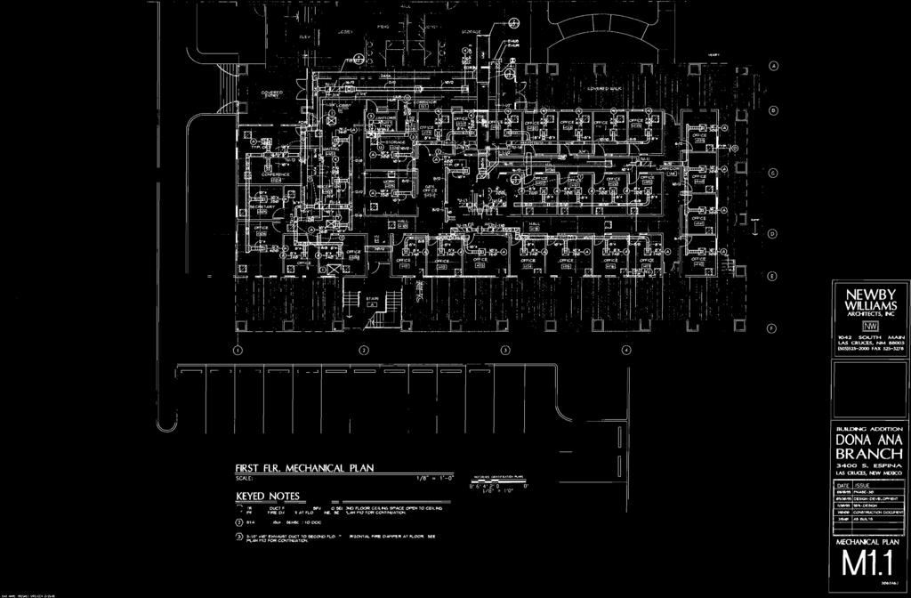
8 V. Plans and Schematics 1. Return Air Flow Schematic 2. Estimated Static Pressure Requirements for Return Air Path into AHU 3. Fire Damper Loss (node 2) 4. Opening Loss (node 2) 5. Opening Loss (node 3) 6. Return Air Control Damper to AHU Loss (node 5) existing condition 7. Return Air Control Damper to AHU Loss (node 5) original design 8. Return Air Control Damper to AHU Loss (node 5) revised size condition 9. Enlarged AHU Room Plan 10. First Floor Return Air Flow Diagram 11. Second Floor Return Air Flow Diagram 12. Phase 1 HVAC Plans Indicating location of static pressure controller 13. Phase 2 HVAC Plan First Floor Indicating location of static pressure controller
9
10 Estimated Static Pressure Requirements for Return Air Path into AHU Supply fan revisions control revisions, single static pressure control, fan section modification to eliminate segregated supply fan rooms. Return revisions Air handler return opening modification, outside air modification. Sound attenuators (ST): ST-1 54 x 12 X 3 = 4.5 sq. ft. ST-2 & 3 42 X 30 X3 = 8.75 sq. ft. ST 2 & 3(4) 7438 CFM/ 8.75 SF = 850 FPM =.04 in. wg. Pressure drop ST-1 (4) 3533 CFM/ 4.5 sf = 785 FPM =.03 in. wg. Pressure drop Return Air Opening and Damper: (5) 3 x 35,770 CFM = 2191 fpm =0.49 in. wg. Pressure drop (0.21 wg revised opening) Return Air path: Transfer duct up to 2 nd floor (2) in. wg. loss Entrance into transfer duct up to 2 nd Floor(2) Across Fire damper (2) Transfer duct across corridor(3) Entrance into transfer duct across corridor(3) RA grille 850 CFM(1) Estimated Static Pressure Loss thru return path(s) 1.42 To AHU return opening at mixing box Total Return Air Losses to AHU Filter Bank = =1.95 in. wg. (Current installation) Total Return Air Losses to AHU Filter Bank = =1.67 in. wg. (Revised return air opening installation)
11
12

13

14
15
: 16 Jamb Seal: 304 SS Sizing: Nominal Transition: None Blade")
 Notes: All dimensions shown are in units of inches. Width & Height furnished approximately 0.25 in. under size. Installation instructions available at www.greenheck.com.")
16 Printed Date: 5/10/2016 Job: DACC Air Handler Mark: Mark 1 Model: VCD-33 Ratings and General Construction Blade Action: Opposed Axle Bearings: Synthetic Standoff Bracket: None Frame Type: Channel Axle/Linkage Material: Steel Jackshafting: No Preference Material: Galvanized Blade Seal: TPE Clean Wrap: No Frame Thickness (ga): 16 Jamb Seal: 304 SS Sizing: Nominal Transition: None Blade Indicator: None Temp. Rating (ºF): 180 Actuator Sizing: Default SqFt Actuator Actuator Type: None Actuator Mounting: External Actuator Location: Left Side Width Height 1.25 in. max. (typical) Notes: All dimensions shown are in units of inches. Width & Height furnished approximately 0.25 in. under size. Installation instructions available at Standard Flange Frame 5 in. Application & Design The model VCD-33 is a low leakage control damper for application as an automatic control or manual balancing damper. This model is intended for applications in low to medium pressure and velocity systems. A wide range of electric and pneumatic actuators are available. Non-jackshafted dampers will be supplied with a blade drive lever for internal actuator mounting. When external actuaor mounting is specified, an extension pin with clip kit will be provided. Note: The extension pin with clip kit includes the extension pin and clip. Ratings Pressure: Up to 10 in. wg pressure differential Velocity: 4,000 ft/min Leakage: Class 1 in. wg, Class up to 8 in. wg Temperature: Up to 250 F Greenheck Fan Corporation certifies that the model VCD-33 shown herein is licensed to bear the AMCA Seal. The ratings shown are based on tests and procedures performed in accordance with AMCA Publication 511 and comply with the requirements of the AMCA Certified Ratings Programs. The AMCA Certified Ratings Seal applies to Air Leakage and Air Performance ratings. Row ID Tag Qty Opening W (in.) Opening H (in.) Drive Arrangement 1-1 Return AHU Drive-CC-12-2CEL-0 Performance Calculation (Informational purposes only. Not actual damper rating.) Volume Velocity Pressure Drop Row ID AMCA (CFM) (ft/min) (in. wg) 1-1 AMCA ,770 1, Total Qty: 1 CAPS H:\2015 Projects\15104\Drawings\15104 DACC Air Handler.gfcj Page 1 of 2
17
18
19


20


21


22 VI. Photos of Existing AHU Figure 1 - Ceiling return air path in top of AHU room. Figure 2 - Fire damper in AHU room wall for return path.


23 Figure 3 - Fire damper in AHU room wall for return air opening. Figure 4 - Open wall into ceiling space from AHU room. Supply duct from SF in foreground. Fire damper return air opening adjacent to right.


24 Figure 5 - Typical congested ceiling space in building. Figure 6 - Building ceiling space.

25 Figure 7 - Outside air control damper inside AHU mixing section. Control damper opens to outside air intake plenum and louver on wall of building.

26 Figure 8 - Return air control damper/return air opening from building into AHU mixing section. Located on top of AHU casing and opens to AHU room pulling return air through building ceiling space to AHU.


27 Figure 9 - Pre-filter bank inside mixing section of AHU. Figure 10 - Bag filter section on downstream side of pre-filters. See figure 9 above.


28 Figure 11 - AHU cooling coil sections, downstream of bag filter bank. Figure 12 - Supply duct from supply fan section to second floor air distribution system.


29 Figure 13 - Supply duct from supply fan section with smoke detector. Figure 14 - Supply duct from supply fan section down to first floor air distribution system.


30 Figure 15 - Supply duct connections. Figure 16 - Supply fan. Typical of two.
AIR DISTRIBUTION. C. Section Building Automation and Control System Guidelines. D. Section Fire Alarm System & Detection Systems
 233100 AIR DISTRIBUTION PART 1: GENERAL 1.01 RELATED SECTIONS A. Section 230700 HVAC Insulation B. Section 237300 Air Handling C. Section 230900 Building Automation and Control System Guidelines D. Section
SECTION AIR DUCT ACCESSORIES
 SECTION 23 33 00 AIR DUCT ACCESSORIES PART 1 - GENERAL 1.1 SUMMARY A. Section includes back-draft dampers, combination fire-and-smoke dampers, duct access doors, fire dampers, smoke dampers, volume control
Guide Spec Summary. Option List. Date: 05/21/2001. EarthWise VAV Terminal Units Full Spec. Prepared by: Phone Number: Prepared for:
 Date: 05/21/2001 Time: 02:57:44 PM Job Name: EarthWise VAV Terminal Units Full Spec Location: AnyTown, Earth Prepared by: Phone Number: Prepared for: Guide Spec Summary Option List SINGLE & DUAL DUCT UNIT
Florida Department of Transportation
 Page 1 of 7 RICK SCOTT GOVERNOR Florida Department of Transportation 1109 S. Marion Avenue Lake City, Florida 32025 ANANTH PRASAD SECRETARY September 27, 2011 To: Proposal Holders Addendum No: 1, E2Q23,
Civil Engineering Building
 Continuous Commissioning Report For the Civil Engineering Building Building 492 Submitted to: Utilities Energy Office Physical Plant Department Texas A&M University Prepared by: Energy Systems Laboratory
SECTION SEQUENCE OF OPERATION FOR HVAC CONTROLS PART 1 GENERAL
 SECTION 15910 SEQUENCE OF OPERATION FOR HVAC CONTROLS PART 1 GENERAL 1.1 RELATED DOCUMENTS A. Drawings and general provisions of the Contract, including General and Supplementary Conditions and other Division
OSU Alumni Center Phase I Implementation Review. Oregon State University 130 Oak Creek Bldg. Corvallis, Oregon
 OSU Alumni Center Phase I Implementation Review Prepared for Oregon State University 130 Oak Creek Bldg. Corvallis, Oregon 97331 October 31, 2011 Job No. 02.11.00113 Introduction: Glumac was engaged by
City of Duluth Festival Center 04/25
 SECTION 230593 - TESTING, ADJUSTING, AND BALANCING FOR HVAC PART 1 - GENERAL 1.1 RELATED DOCUMENTS A. Drawings and general provisions of the Contract, including General and Supplementary Conditions and
4. OVERVIEW OF MECHANICAL SYSTEM
 4. OVERVIEW OF MECHANICAL SYSTEM The 87,000 SF SLCC is served by six (6) Trane M-Series Climate Changer Air Handing Units (AHUs). Each unit serves a distinct zone within the facility that is unique in
Computing Services Center
 Continuous Commissioning Report for the Computing Services Center Building #516 Submitted to: Utilities Energy Office Physical Plant Department Texas A&M University Prepared by: Energy Systems Laboratory
Technical Assignment 3 11/15/04. Executive Summary
 Executive Summary This report is an analysis of the existing systems within the Outreach Innovation Building in University Park, PA. One significant design criteria was a lower than average noise criteria
Brown University Revised August 3, 2012 Facilities Design & Construction Standards SECTION AIR HANDLING UNITS
 SECTION 23 70 00 AIR HANDLING UNITS PART 1. GENERAL 1.1 Section includes air-handling units to 15,000 cfm and accessories. 1.2 Related Sections 1 : A. Division 01 - Brown University Standard for Narragansett
FIRE & SMOKE DAMPERS. Meeting tomorrow's requirements for fire and smoke protection today.
 FIRE & SMOKE DAMPERS Meeting tomorrow's requirements for fire and smoke protection today. LATEST TECHNOLOGY For more than 40 years Ruskin has led the HVAC industry in the manufacture of dampers and louvers.
Life Safety Dampers Selection and Application Manual
 Life Safety Dampers Selection and Application Manual Ceiling Radiation Dampers Fire Dampers Combination Fire Smoke Dampers Smoke Dampers August 2016 1 2 Table of Contents HOW TO USE THIS MANUAL DAMPER
Air Handler Unit (AHU) Equipment Purchase and Delivery Invitation to Bid
 Equipment Purchase and Delivery Invitation to Bid") DATE: February 1, 2018 SUBJECT: Letter of Clarification #2 RE: TO: Air Handler Unit (AHU) Equipment Purchase and Delivery Invitation to Bid All Prospective Bidders Houston First Corporation ( HFC ) issues
DATE: February 1, 2018 SUBJECT: Letter of Clarification #2 RE: TO: Air Handler Unit (AHU) Equipment Purchase and Delivery Invitation to Bid All Prospective Bidders Houston First Corporation ( HFC ) issues
Guide Spec Summary. Option List. Date: 05/21/2001. EarthWise Modular Climate Changer Full Spec. Prepared by: Phone Number: Prepared for:
 Date: 05/21/2001 Time: 08:50:16 AM Job Name: EarthWise Modular Climate Changer Full Spec Location: Any Town, Earth Prepared by: Phone Number: Prepared for: Guide Spec Summary Option List SUBMITTALS Submittals
Tunnel Transit Dampers. Heavy Duty Tunnel Transit Life Safety
 Tunnel Transit Dampers Heavy Duty Tunnel Transit Life Safety November 2011 Heavy Duty/Industrial Tunnel Dampers Applications Dampers in subway tunnels and transit systems serve three primary functions,
UNIVERSITY OF MISSOURI Heating Ventilating and Air-Conditioning (HVAC) 2016 Q1
 2016 Q1") GENERAL: This section provides general standards for overall sizing and design of Heating, Ventilating, and Air Conditioning (HVAC) systems. Other sections contain specific standards for each system per
GENERAL: This section provides general standards for overall sizing and design of Heating, Ventilating, and Air Conditioning (HVAC) systems. Other sections contain specific standards for each system per
Rosemex Products 96 VENTILATION CLIMATAIR COMPARTMENT AIR HANDLING UNITS
 10 Rosemex Products 96 VENTILATION CLIMATAIR COMPARTMENT AIR HANDLING UNITS 2 INDEX Page Description - Introduction -Application - Data... 2 Typical Installation... 3 Sound performance... 3-6 Dimensional
SECTION SEQUENCE OF OPERATIONS FOR HVAC CONTROLS
 SECTION 23 09 93 SEQUENCE OF OPERATIONS FOR HVAC CONTROLS PART 1 - GENERAL 1.1 SUMMARY A. This Section includes control sequences for HVAC systems, subsystems, and equipment. B. See Division 23 Section
Tunnel Transit Dampers Heavy Duty Tunnel Transit Life Safety
 Tunnel Transit Dampers Heavy Duty Tunnel Transit Life Safety November 2017 Heavy Duty/Industrial Tunnel Dampers Applications Dampers in subway tunnels and transit systems serve three primary functions,
Linear Floor Heaters
 Linear Floor Heaters The Price Linear Floor Heater family provides ultimate flexibility in terms of style, performance, and ease of installation. Using room-side heat virtually eliminates the requirement
15900 HVAC INSTRUMENTATION AND CONTROLS
 15900 HVAC INSTRUMENTATION AND CONTROLS PART 1 GENERAL - Andover Controls BAS system is the standard for the University, and may be specified as a proprietary item. 1.0 RELATED DOCUMENTS A. Drawings and
Plenum Fans. Model HPA. Direct Drive
 Plenum Fans Model HPA Direct Drive October 2012 Quiet & Efficient HPA Plenum Fans Greenheck s modular plenum fan, model HPA, is designed and engineered to provide superior performance and reliability in
Continuous Commissioning: A Valuable Partner to Retrofit Projects
 Continuous Commissioning: A Valuable Partner to Retrofit Projects Yeqiao Zhu Aamer Athar Kenneth Banks Ph.D. PE, CEM PE, CEM Energy Systems Laboratory Sempra Energy Solutions Sempra Energy Solutions Charles
Life Safety Damper Installation ASHRAE St Louis Chapter Feb. 9,2015. Peter McDonnell, PE, LEED AP BD+C McClure Engineering
 Life Safety Damper Installation ASHRAE St Louis Chapter Feb. 9,2015 Peter McDonnell, PE, LEED AP BD+C McClure Engineering UL DAMPER TEST STANDARDS UL 555 - FIRE DAMPERS UL555S SMOKE DAMPERS UL555C CEILING
Electric Duct Heaters. IDHB & IDHC Series
 Electric Duct Heaters IDHB & IDHC Series May 2014 1 Duct Heaters Greenheck has a complete line of configurable electric duct heaters that are perfectly suited to your HVAC application. Our CAPS configuration
DIVISION 23 - HVAC HVAC Air Distribution
 PART 1 - GENERAL 1.01 GENERAL CRITERIA A. General Design Criteria 1. System standards require that buildings be fully ducted (supply, exhaust and return air). 2. Provide positive exhaust ventilation for
Modular Supply Make-Up Air Unit
 Modular Supply Make-Up Air Unit Model MSX Flexible Design Factory Assembled Heating Options Hot Water Steam Electric Cooling Options Evaporative Direct Expansion Chilled Water November 2009 Product Features
Union County Vocational - Technical Schools Scotch Plains, New Jersey
 SECTION 230593 - TESTING, ADJUSTING, AND BALANCING FOR HVAC PART 1 - GENERAL 1.1 SUMMARY A. Section Includes: 1. Balancing Air Systems: a. Constant-volume air systems. b. Variable-air-volume systems. 2.
SECTION SEQUENCE OF OPERATIONS FOR HVAC CONTROLS
 PART 1 - GENERAL SECTION 23 09 93 SEQUENCE OF OPERATIONS FOR HVAC CONTROLS 1.1 SUMMARY A. This Section includes control sequences for HVAC systems, subsystems, and other equipment. B. See Division 23 Section
Engineering Guide VAV Diffusers. Please refer to the Price Engineer s HVAC Handbook for more information on VAV Diffusers.
 VAV Diffusers lease refer to the rice Engineer s HVAC Handbook for more information on VAV Diffusers. Diffuser Types Ceiling Diffusers Conventional air distribution systems typically group several rooms
Retrocommissioning Findings Summary: Building X #1 Priority: Major Comfort/Control Problems
 IMPORTANT NOTICE: This sample document is provided for instructional purposes only. CCC is not rendering advice concerning any commission project or practices. This document is neither approved nor intended
SECTION DUCTWORK
 SECTION 15890 DUCTWORK PART 1 GENERAL 1.01 SUMMARY A. Related Sections: 1. 07270 - Firestopping and Fire and Smoke Barrier Caulking. 2. 15260 - Vibration Isolation. 3. 15280 - Thermal Insulation (HVAC).
DIVISION 23 - HVAC HVAC Air Distribution
 PART 1 - GENERAL 1.01 GENERAL CRITERIA A. General Design Criteria 1. System standards require that buildings be fully ducted (supply, exhaust and return air). 2. Provide positive exhaust ventilation for
B. Use UT Austin specifications and equipment schedule format for HVAC equipment where available.
 PART 1: GENERAL 1.01 General Requirements A. This standard is intended to provide useful information to the Professional Service Provider (PSP) to establish a basis of design. The responsibility of the
Job Name Control Systems Description Date
 Job Name Control Systems Description Date Project Overview The project is a describe the building and its major HVAC systems (e.g. three-story office building, served by a rooftop unit VAV system ). In
FAN TERMINAL UNITS Constant Volume (Series Flow), Standard Design
, Standard Design") FAN TERMINAL UNITS Constant Volume (Series Flow), Standard Design Fan motor (PSC or ECM). UL Listed 1 insulation conforms to UL Test 181 and NFPA 90A. Plenum air filter rack. (Filter Optional) Casing has
FAN TERMINAL UNITS Constant Volume (Series Flow), Standard Design Fan motor (PSC or ECM). UL Listed 1 insulation conforms to UL Test 181 and NFPA 90A. Plenum air filter rack. (Filter Optional) Casing has
ADDENDUM No: 3 JOSEPHINE COUNTY BUILDING OPERATIONS DEPARTMENT. February 29, NO CHANGE: March 8, 2012 / NOT LATER THAN 2:00 PM
 ADDENDUM No: 3 JOSEPHINE COUNTY BUILDING OPERATIONS DEPARTMENT February 29, 2012 RFP NO: 17 PROJECT: Josephine County Justice Center HVAC Upgrades BID CLOSING DATE: NO CHANGE: March 8, 2012 / NOT LATER
Cleveland Clinic Design Standards MECHANICAL SYSTEMS DESIGN GUIDELINES HVAC AIR DISTRIBUTION PART I - GENERAL 1.1 SUMMARY
 PART I - GENERAL 1.1 SUMMARY A. This section addresses the general requirements for air handling distribution systems, including air handlers, ductwork, ductwork accessories, terminal units, air devices,
DESIGNING MODULAR VAV SYSTEMS
 FORM 5.2 REV 0905 THERMA-FUSER THERMALLY POWERED VAV DIFFUSER DESIGNING MODULAR VAV SYSTEMS MODULAR VAV SYSTEMS The Therma-Fuser diffuser is a simple stand alone device that provides VAV control when supplied
GreenJet Transfer Fans
 GreenJet Transfer Fans Model GJX High Performance Axial Transfer Fan April 2018 GreenJet As cars park in an underground parking structure, carbon monoxide (CO) and other noxious fumes are emitted into
INSTRUMENTATION AND CONTROL DEVICES FOR HVAC
 PART 1 GENERAL 1.01 RELATED REQUIREMENTS SECTION 23 0913 INSTRUMENTATION AND CONTROL DEVICES FOR HVAC A. Section 26 2717 - Equipment Wiring: Electrical characteristics and wiring connections. 1.02 ADMINISTRATIVE
Type FKS-EU COMPACT DIMENSIONS, IDEAL FOR RESTRICTED SPACES. Homepage > Products > Fire and Smoke Protection > Fire dampers > Type FKS-EU
 Homepage > Products > Fire and Smoke Protection > Fire dampers > Type FKS-EU Type FKS-EU COMPACT DIMENSIONS, IDEAL FOR RESTRICTED SPACES Small rectangular fire damper for the isolation of duct penetrations
DIVISION 15 MECHANICAL
 DIVISION 15 MECHANICAL A. GENERAL DESIGN CONDITIONS 1. Design occupied spaces to maintain 72 F and a space dew point temperature not to exceed 55 F. 2. Design classroom and office space buildings with
Kings County Jail Expansion Phase 3 Rational Analysis of Smoke Control System
 Kings County Jail Expansion Phase 3 Rational Analysis of Smoke Control System Kings County Jail Phase 3 Page 2 RATIONAL ANALYSIS OF SMOKE CONTROL SYSTEM PER 2013 CBC 909.4 General Description: The project
1.1 This section applies to air handling units for HVAC Systems.
 AIR HANDLING UNITS GENERAL INFORMATION 1.1 This section applies to air handling units for HVAC Systems. DESIGN REQUIREMENTS 2.1 Design Criteria a. The decision to use modular central station air handling
Registration Number: Registration Date/Time: HERS Provider: CA Building Energy Efficiency Standards 2013 Residential Compliance June 2014
 (Page 1 of 3) A. System Information 01 Space Conditioning System Identification or Name: 02 Space Conditioning System Location or Area Served: 03 Building Type from CF1R 04 05 Verified Low Leakage Ducts
Pharmaceutical Facility Design
 PhEn-602 Pharmaceutical Facility Design J. Manfredi Notes 9A PhEn-602 J. Manfredi 1 Primary & Secondary HVAC units Primary Primary air handling unit arrangement: One unit is responsible for all of the
A. Base Bid: 1. Heating Contractor provide: a. Control sequences for HVAC systems, subsystems, and equipment.
 SECTION 23 09 93 - SEQUENCE OF OPERATIONS FOR HVAC CONTROLS PART 1 - GENERAL 1 WORK INCLUDES A. Base Bid: Heating Contractor provide: Control sequences for HVAC systems, subsystems, and equipment. B. Alternate
Advance Product Data. Features/Benefits. 42WKN Hydronic Fan Coil Units
 Advance Product Data 42WKN Hydronic Fan Coil Units 3 4 to 2 1 2 Tons UNIT SIZES 004-010 UNIT SIZES 016,020 The new Carrier Hydronic Cassette offers a modern solution for a wide variety of small and medium
Louvers & Dampers April Product Guide Specification SECTION COMBINATION FIRE SMOKE DAMPERS
 Louvers & Dampers April 2008 P.O. Box 606 7435 Industrial Road Florence, Kentucky, 41042 Phone: (859) 647-2299 Fax: (859) 647-7810 Web Site: www.louvers-dampers.com Product Guide Specification SECTION
Fan Arrays. White Paper. Energy Labs White Paper Series Volume 0412 Issue 001 April 2012 Rev. 0. Series
 White Paper Series Volume 0412 Issue 001 April 2012 Rev. 0 Copyright Energy Labs Inc. All rights reserved. Energy Labs Inc. and EnergyLabs Inc. logo are registered trademarks of Energy Labs Inc. in the
Energy Recovery with Cooling and Heating
 Energy Recovery with Cooling and Heating VersiVent - Model VER Commercial Institutional 2,000-10,000 cfm 3.0 in. wg external static pressure Configurable September 2008 Page The VersiVent Header Model
BULLETIN. Temperature Controls (Chilled Water) Phase III only (3/11/2010)
 Phase III only (3/11/2010)") BULLETIN Temperature Controls (Chilled Water) Phase III only (3/11/2010) This bulletin is to advise you of the fees and responsibilities associated with the tenant s temperature controls. Tenant Responsibility:
BULLETIN Temperature Controls (Chilled Water) Phase III only (3/11/2010) This bulletin is to advise you of the fees and responsibilities associated with the tenant s temperature controls. Tenant Responsibility:
The Creative and Performing Arts High School (CAPA) Pittsburgh, PA 11/11/2002 Andrew Tech Mechanical Option Prof. S. A. Mumma
 Pittsburgh, PA 11/11/2002 Andrew Tech Mechanical Option Prof. S. A. Mumma") Objectives and Requirements For the Creative and Performing Arts High School (CAPA), the main objective of the mechanical design is to provide an energy efficient system that is easily maintainable and
Objectives and Requirements For the Creative and Performing Arts High School (CAPA), the main objective of the mechanical design is to provide an energy efficient system that is easily maintainable and
AIR HANDLING. B. Section Building Automation and Control System Guidelines. C. Section Air Cleaning Devices and Filters
 237300 AIR HANDLING PART 1: GENERAL 1.01 RELATED SECTIONS A. Section 230530 Clean Steam Generation B. Section 230900 Building Automation and Control System Guidelines C. Section 234100 Air Cleaning Devices
Problems Air and Water Distribution Systems
 Problems Air and Water Distribution Systems ME419 D. Abata 1. Cooled air at 1 atm, 50 F, and 10% relative humidity is transported in a 600 ft long circular sheet metal duct at a rate of 800 cfm. If the
A. General: Refer to paragraph entitled "SUBMITTAL" in Section Include the following data:
 SECTION 15860 - FANS PART 1 - GENERAL 1.01 RELATED DOCUMENT A. Basic Requirements: Provisions of Section 15010, BASIC MECHANICAL REQUIREMENTS, and Section 15030, ELECTRICAL REQUIREMENTS FOR MECHANICAL
DIGI3U. Zoning Systems. Installation Guide. That s all we do. Three-Zone, Universal Controller for Gas/Electric or Heat Pump Applications
 Installation Guide DIGIU Three-Zone, Universal Controller for Gas/Electric or Heat Pump Applications -Zone Controller for the RNC Market Part #DMAN October 004 Zoning Systems That s all we do. INTRODUCTION
FORM EG2 (502) FlexSys Configured Packaged Rooftop Air Conditioning Units
 FlexSys Configured Packaged Rooftop Air Conditioning Units") FORM 100.50-EG2 (502) TM FlexSys Configured Packaged Rooftop Air Conditioning Units TABLE OF CONTENTS PAGE TOTAL INTEGRATED HVAC SYSTEM... 3 AN INTEGRATED SOLUTION... 4 INTRODUCTION... 6 System Description...
FORM 100.50-EG2 (502) TM FlexSys Configured Packaged Rooftop Air Conditioning Units TABLE OF CONTENTS PAGE TOTAL INTEGRATED HVAC SYSTEM... 3 AN INTEGRATED SOLUTION... 4 INTRODUCTION... 6 System Description...
UNIVERSITY SERVICES ANNEX James Madison University Harrisonburg, Virginia State Project Code: Architect s Project Number:
 SECTION 233423 - HVAC POWER VENTILATORS PART 1 - GENERAL 1.1 RELATED DOCUMENTS A. Provisions of the Contract and of the Contract Documents apply to this Section. 1.2 PERFORMANCE REQUIREMENTS A. Operating
UNIVERSITY OF MISSOURI Central Station Air-Handling Units March
 GENERAL: 1. This section provides criteria for the design and installation of air handling units. DESIGN GUIDELINES: Design General 1. Location 1.1. For new construction, and existing buildings where possible,
SEQUENCE OF OPERATION GUIDELINE. AIR TERMINAL UNITS SINGLE DUCT VARIABLE AIR VOLUME with HOT WATER REHEAT or ELECTRIC HEAT
 SEQUENCE OF OPERATION GUIDELINE AIR TERMINAL UNITS SINGLE DUCT VARIABLE AIR VOLUME with HOT WATER REHEAT or ELECTRIC HEAT Document: VAV-HTG rev1 Revision: 1.0 Rev. Date: July 22, 2011 NOTES: 1. THIS SEQUENCE
Submitted to. Texas A&M University-Corpus Christi The Texas A&M University System. Submitted by. Yeqiao Zhu Dan Turner David Claridge
 ESL-TR-99/12-04 Report of Energy Efficiency Study and Metering/Utilities Profile for Electricity Deregulation at the Texas A&M University-Corpus Christi (TAMU-CC) Corpus Christi, Texas Submitted to Texas
Element D Services Heating, Ventilating, and Air Conditioning
 Air Handling Distribution PART 1 - GENERAL 1.01 OVERVIEW A. This section describes criteria for design of facility air handling distribution systems, including air handlers, ductwork, ductwork accessories,
RE: Phase 2 Improvements DATE: July 1, 2016 New Administration Building Wernle Youth & Family Treatment Center 2000 Wernle Road Richmond, Indiana
 ADDENDUM NO. 2 RE: Phase 2 Improvements DATE: July 1, 2016 New Administration Building Wernle Youth & Family Treatment Center 2000 Wernle Road Richmond, Indiana TO: All Bidders Gentlemen: This Addendum
1080 Marina Village Parkway, Suite 501 Alameda, CA (510) Fax (510) HVAC DESIGN INTENT
 Fax (510) HVAC DESIGN INTENT") Taylor Engineering 1080 Marina Village Parkway, Suite 501 Alameda, CA 94501-1142 (510) 749-9135 Fax (510) 749-9136 LLC HVAC DESIGN INTENT PART 1 - GENERAL 1.1 Overview A. The project consists of a 3-story
Taylor Engineering 1080 Marina Village Parkway, Suite 501 Alameda, CA 94501-1142 (510) 749-9135 Fax (510) 749-9136 LLC HVAC DESIGN INTENT PART 1 - GENERAL 1.1 Overview A. The project consists of a 3-story
WHITE PLAINS SMOKE CONTROL CODE PART 1. GENERAL REQUIREMENTS
 WHITE PLAINS SMOKE CONTROL CODE a. Application of Code. PART 1. GENERAL REQUIREMENTS The following uniform standards and procedures shall apply to the design, installation and testing of new smoke purge
Building Automation System (BAS) Design Criteria
 Design Criteria") 25 0520 Building Automation System (BAS) Design Criteria 1. Design Statement a. During the various design phases of this project, the Engineer will develop options and strategies for selection of the appropriate
25 0520 Building Automation System (BAS) Design Criteria 1. Design Statement a. During the various design phases of this project, the Engineer will develop options and strategies for selection of the appropriate
Modular Heating & Ventilating Unit Model IGX-HV
 Modular Heating & Ventilating Unit Model IGX-HV Indirect Gas-Fired Heating Evaporative Chilled Water DX Cooling October 2008 Product Features Model IGX-HV Indirect Gas-Fired Heating and Ventilating Unit
H3/V3 Series Horizontal and Vertical Indoor Air Handling Units. Engineering Catalog
 H3/V3 Series Horizontal and Vertical Indoor Air Handling Units Engineering Catalog Table of Contents AAON H3/V3 Series Features and Options Introduction... 6 H3/V3 Base Model Description... 7 Unit Size...
VERSECON Indoor Vertical Self-Contained Air Conditioner YSWU Ton Water-Cooled
 FORM 145.05-EG1 (1004) VERSECON Indoor Vertical Self-Contained Air Conditioner YSWU 10 105 Ton Water-Cooled Table of Contents FORM 145.05-EG1 (0804) Features and Benefits.....................................................
LGH/LCH WARNING. CAUTION Danger of sharp metallic edges. Can cause injury. Take care when servicing unit to avoid accidental contact with sharp edges.
 Service Literature The LGH/LCH high and standard efficiency 5, 0, 5 and 50 ton (, 0.7, 58. and 75.9 kw) units, are configure to order units (CTO) with a wide selection of factory installed options. The
Digital Precise Air Control - DPAC
 Digital Precise Air Control - DPAC Mode Enable Sensor Options The temperature of this sensor will determine if the unit is in heating, cooling or vent mode during Occupied operation. The following options
DACC - NMDA BUILDINGS
 A PROJECT FOR: LAS CRUCES, NEW MEXICO PROJECT LOCATION LOCATION MAP INDEX OF DRAWINGS: CV001 - COVER SHEET M101 - OVERALL CAMPUS STEAM UTILITY PLAN M102 - DACC DAMA 341 PLAN M103 - DACC LRC & CLASSROOM
Installation and Maintenance Manual IM 1102
 Installation and Maintenance Manual IM 1102 Parallel Fan Powered Variable Air Volume (VAV) Terminal Box Group: Applied Air Systems Part Number: IM 1102 Date: October 2010 Model MQFVI5 Table of Contents
Technical Report #3 Mechanical Systems Existing Conditions Evaluation
 Mechanical Option Technical Report #3 Technical Report #3 Mechanical Systems Existing Conditions Evaluation Instructor: Dr. Bahnfleth 11.15.04 Building Sponsor: CCG Facilities Integration Table of Contents
SMOKE DAMPERS AIRFOIL STAINLESS STEEL
 MODEL SERIES 1210M AIROIL BLADE MODULATING ACTUATOR Model Series 1210M Modulating Smoke Dampers are classified for use as a volume control damper in applications where building codes require a leakage
DACC & NMDA Central Steam Disconnect Study
 DACC & NMDA Central Steam Disconnect Study NMSU Facilities and Services Department P.O. Box 30001 Las Cruces, NM 88003-8001 June 14, 2016 Final submittal 1065 S. Main St., Bldg. D, Ste. A Las Cruces, New
HVAC Controls Upgrades: Requirement Details ( )
") REQUIRED CONTROLS/FEATURES HVAC non CENTRAL PLANT 1) Zone Level Scheduling & Override for all air handlers (supply and exhaust) to match occupied hours by zone DDC or occupancy sensors (OS) allowed. (403.2.4.3,
REQUIRED CONTROLS/FEATURES HVAC non CENTRAL PLANT 1) Zone Level Scheduling & Override for all air handlers (supply and exhaust) to match occupied hours by zone DDC or occupancy sensors (OS) allowed. (403.2.4.3,
1. When using the COMcheck software, the compliance report submitted by the permit holder shall indicate that the applicable code is.
 2018 NC Energy Conservation Code Commercial Mechanical Module 7 CHAPTER 5 [CE] WORKSHEET 1. When using the COMcheck software, the compliance report submitted by the permit holder shall indicate that the
Air Conditioning Clinic
 Air Conditioning Clinic VAV Systems One of the Systems Series July 2012 TRG-TRC014-EN VAV Systems One of the Systems Series A publication of Trane Preface VAV Systems A Trane Air Conditioning Clinic Figure
AIR HANDLERS. Central Station (CS3) Roof Mounted (RT) (Modular AL Frame AHU)
 Roof Mounted (RT) (Modular AL Frame AHU)") AIR HANDLERS Central Station (CS3) (Modular AL Frame AHU) Roof Mounted (RT) CONTENTS 1. CS3 Modular Aluminium Frame AHU : Unit Types 2. Casing Structure 3. Blowers and Drives 4. Coils 5. Options and Accessory
AIR HANDLERS Central Station (CS3) (Modular AL Frame AHU) Roof Mounted (RT) CONTENTS 1. CS3 Modular Aluminium Frame AHU : Unit Types 2. Casing Structure 3. Blowers and Drives 4. Coils 5. Options and Accessory
SECTION TESTING, ADJUSTING, AND BALANCING FOR HVAC
 SECTION 23 05 93 PART 1 - GENERAL 1.1 DESCRIPTION SPEC WRITER NOTES: 1. Use this section only for NCA projects. 2. Delete between // // if not applicable to project. Also delete any other item or paragraph
DARTMOUTH COLLEGE DESIGN January 3, 2012 & CONSTRUCTION GUIDELINES
 SECTION 15856 MODULAR AIR HANDLING UNITS PART 1 DESIGN DIRECTIVES 1.1 QUALITY ASSURANCE A. NFPA Compliance: Modular air handling units and components shall be designed, fabricated, and installed in compliance
HVAC Controls Upgrades: Requirement Details ( )
") REQUIRED CONTROLS/FEATURES To qualify the upgrade must add or substantially modify 3 or more sequences/system capabilities. Also, all sequences and items listed under the required section are needed in
REQUIRED CONTROLS/FEATURES To qualify the upgrade must add or substantially modify 3 or more sequences/system capabilities. Also, all sequences and items listed under the required section are needed in
ASHRAE Region VI CRC Track III: Session 3 Ventilation Energy Recovery. Steven T. Taylor, PE Principal Taylor Engineering
 ASHRAE Region VI CRC Track III: Session 3 Ventilation Energy Recovery Steven T. Taylor, PE Principal Taylor Engineering This program is registered with the AIA/CES for continuing professional education.
1.03 RELATED SECTIONS: The following sections contain requirements that relate to this section.
 SECTION 15855 GAS FURNACE/DX COOLING UNIT PART 1 - GENERAL 1.01 RELATED DOCUMENTS A. Drawings and general provisions of contract including General and Supplementary Conditions of Division 1 of Specification
INTRODUCTION TO: ASHRAE STANDARD 90.1, HVAC System Requirements for Reducing Energy Consumption in Commercial Buildings
 INTRODUCTION TO: ASHRAE STANDARD 90.1, 2013 HVAC System Requirements for Reducing Energy Consumption in Commercial Buildings Rocky Mountain ASHRAE Technical Conference, April 29, 2016 SEAN BEILMAN, P.E.,
Andrea Borowski The Pennsylvania State University University Park, PA November 11, 2002 Consultant: Dr. Bahnfleth Technical Assignment M-3
 Existing System Evaluation Executive Summary The MBNA Career Services Center is a 44,000 square foot, 4-story office type building at Penn State University, University Park Campus. The building is located
Advance Release September 2009
 Vertical Air Cooled DSV Series R 410A Model DSV096 DSV120 DSV144 DSV180 Nominal Cooling (Tons) 8 10 12 15 Refrigerant R 410A R 410A R 410A R 410A Cooling Performance Gross Cooling Capacity(Btu/h) 95,000*
Harrington Tower Building
 Continuous Commissioning Report For the Harrington Tower Building Building #435 Submitted to: Utilities Energy Office Physical Plant Department Texas A&M University Prepared by: Energy Systems Laboratory
Presented by: Bill Lauzon, PE Lauzon Life Safety Consulting, LLC Web: Lauzon-LSC.com
 Presented by: Bill Lauzon, PE Lauzon Life Safety Consulting, LLC 262-945-4567 Lauzon.lsc@gmail.com Web: Lauzon-LSC.com 1 Wis Professional Engineer Experienced Facility Director Experienced AHJ WHEA Code
Model 8120 and 8126 Safety & Installation Instructions
 Ventilation Controller Model 8120 and 8126 Safety & Installation Instructions FAMILIARIZE YOURSELF WITH THE INSTALLATION INSTRUCTIONS BEFORE STARTING DANGER ATTENTION INSTALLER: To prevent serious injury
Your Home. Jacco & Assoc.
 Your Home Fan on with call for heating or cooling Heating on with call from space thermostat Stage as required to maintain The 75F Basics adj. - First stage of heating shall be heat pump Cooling on with
NORTHWESTERN UNIVERSITY PROJECT NAME JOB # ISSUED: 03/29/2017
 SECTION 23 0594 - TESTING, ADJUSTING, AND BALANCING (TAB) PART 1 - GENERAL 1.1 SUMMARY A. This Section includes testing, adjusting and balancing HVAC systems to provide design conditions as indicated by
R7DA Series TECHNICAL SPECIFICATIONS. FEATURES and BENEFITS. 6 and 7 ½ Ton DOAS Packaged Gas/Electric Units
 TECHNICAL SPECIFICATIONS R7DA Series 6 and 7 ½ Ton DOAS Packaged Gas/Electric Units 5.4 ISMRE Commercial System 81% Steady State Efficiency Standard Features Fits Pre-Existing Curbs High-Efficiency Low
UNIVERSITY OF ALASKA FAIRBANKS DIVISION 25- INTEGRATED AUTOMATION DESIGN STANDARDS SECTION INTEGRATED CONTROL OF FACILITY LAB FUME HOODS
 PART 1 - GENERAL 1.01 General: A. Laboratory ventilation system will ensure the health and safety of laboratory occupants. B. Room pressurization control will utilize airflow tracking to vary the volume
BULLETIN. Temperature Controls (Chilled / Hot Water)
") BULLETIN Temperature Controls (Chilled / Hot Water) (05-07-2013) This bulletin is to advise you of the fees and responsibilities associated with the tenant s temperature controls. Tenant Responsibility:
BULLETIN Temperature Controls (Chilled / Hot Water) (05-07-2013) This bulletin is to advise you of the fees and responsibilities associated with the tenant s temperature controls. Tenant Responsibility: