Biotec. Ökotec 25. Installation and user manual. Bedienungsanleitung. Produktinformation
|
|
|
- Bonnie Summers
- 6 years ago
- Views:
Transcription


1 Biotec Ökotec 25 Installation and user manual AufstellungsProduct information und Bedienungsanleitung Produktinformation
2 Safety information Safety information Basics The boiler must be installed by a competent professional. The Biotec is produced according to current safety requirements. Incorrect use can cause accidents, injury or even death of the user, if the rules for safe use are ignored. This can also cause damages to the boiler or to other items next to the boiler. The specialist responsible for the implementation must explain the proper handling of the boiler to the user. Only use the boiler if it is installed properly. Always follow the instructions of this manual. Every boiler failure must be fixed as soon as possible. Use of the boiler The manufacturer is not responsible for damages resulting from an inappropriate use. In this case, the user is responsible. The operation parameters can only be modified in the range prescribed in this manual. The use of parameters outside the range can cause damages or errors in the system. Prescribed fuel This boiler is designed for the combustion of wood pellets. The use of other fuels is prohibited. Wood pellets are cylindrical and made from wood scraps without additives or chemical binders. The pellets must have specifical dimensions and a low moisture level. STREBEL recommends pellets with a diameter of 6 to 8 mm and a lenght of 10 to 30 mm. Quality and form are prescribed throughste standards ÖNORM 7135 and DIN Only use pellets that comply with ÖNORM, DIN or equal regional stadards. More informations in chapter 3. Risk of electric shock Works with parts marked with this symbol are only to be carried out by an electrician. Text passages with this symbol hold information about electric connections. Caution Working on parts marked with this symbol can cause injury or material damage. Text passages with this symbol hold information about safety precautions. Possible hand injuries Working on parts marked with this symbol can cause hand injuries. Fire hazard Flammable items may not be positioned near the boiler. Text passages with this symbol hold information about fire prevention. Danger of frost Frost forming in the system pipes after a longer period of downtime during the cold season can cause severe damages. Text passages with this symbol hold information about frost prevention. Additional notices Follow regional prescriptions on positioning, installation, operation and disposal of the boiler. Every person with the intend of operating the boiler is prescribed to carefully read this manual. This applies especially for the safety informations. Even persons intending to clean the boiler or perform other maintenance must read this manual. Otherwise, the guaranty expires. This manual is to be stored safely. Possible risks Carbon monoxyde During boiler operation, carbon monoxyde can issue through the boiler doors. Only leave them open as long as necessary. Insufficient vent during operation is critical. Closing the vent of the boiler room or the boiler is prohibited. Signs and symbols Surfaces with high temperatures Touching such surfaces can cause burns. Surfaces marked with this symbol may only be touched when the system is cooled down. Text passages with this symbol hold information about hot boiler parts. 2
3 Contents 1 Boiler features Technical data Fuel Construction and funtion Installation Boiler controller Phases of operation Maintenance Possible malfunctions First start-up Disposal of the boiler Terminal connections
4 1 Boiler features 1.1 General information The boiler Biotec has a modern design and is made of high quality material. The boiler testings were carried out conform to EN 303-5, so the boiler fulfi lls all requirements for the connection to the central heating system. The maximum permitted system pressure is 2.5 bar. This boiler is suitable as central heating system for single- or multi-family-homes, small businesses or workshops. The automatic operation shows to be very user-friedly, because the only action during operation is re-filling the pellet silo every day to every couple of days, depending on the current output. The Biotec includes the silo and pellet screw. The basic design of the boiler features the silo on its right side. On request and for additional charge, the silo can be mounted on the left side resp. a bigger silo can be installed. Pellets make an excellent fuel. Wood pellets are zylindrical and made from wood sraps. The ash-percentage after the combustion is especially low with pellets and accounts for about 1 %. The caloric value of pellets is approx kj/kg, wich means that 2 kg pellets comply to 1 l light heating oil. The storing qualities and the high energy value of pellets make them the ideal replacement for oil or gas. Additionally, they are produced from wood, a regional renewable source. Boiler features 1.2 Conformity declaration The company STREBEL confirms according to EN45014:1998 that the boiler Biotec complies with the following standards: EC-guidelines: MD 98/37/EC PED 97/23/EC LVD 2006/95/EC EMC 2004/108/EC Harmonized standards: EN 303-5:1999; EN :2006; EN :2002; EN 50165:1997+A1; EN :2001; EN ISO :2003; EN ISO :2003; EN 1050:1997 Other standards and technical spezifications: EN 287-1:2004, EN 288-3:1992; EN 10204:2004; EN ISO 7000:2004. Used method for testing conformity: Modul B1 Grenzwert der Emission der Verbrennungsprodukte (Klasse) 3 Certificates: EC Control Type Certifikate Nr. 0745/350/09 Responsible laboratory: TÜV Thüringen e.v. Service-Center Südthüringen, Industriestr.13, D Zella-Mehlis We hereby declare that the mentioned products were produced under safety- and norm prescriptions, guidelines and standards. All working conditions and terms of use comply with this manual. In case the product is changed in a way we are not informed of, this confirmation loses its validity. 4
5 Technical data 2 Technical data Pelletskessel Biotec 25 Biotec 25 S Biotec 40 Rated output kw Minimum output kw Flow-/Return temperature C 90/70 90/70 90/70 Flue gas temperature at rated output C Minimum flue gas temperature C Flue gas volume flow at rated output kg/s 0,0176-0,0280 Flue gas volume flow at min. output kg/s 0,0079-0,0140 Effi ciency % Water volume l Resistance on water side t=10 K/t=20 K hpa 7/2 7/2 7/2 Weight kg Boiler class N Maximum operating/testing pressure bar 2,5/5 2,5/5 2,5/5 Maximum flue draft Pa Connection flow/return inch 1 1 5/4 Exhaust connection diameter mm Ø Pellet silo volume l Maximum volume of silo (extra charge) l Electric connection 230 V ~ 50 Hz (max. 1 A) 230 V ~ 50 Hz (max. 1 A) 230 V ~ 50 Hz (max. 1 A) Power consumption ignition/fan/screw motor W 400/41/50 400/41/50 400/41/50 5
 Boiler width (W2) Height return (R) Height flow (F) Centre exhaust conn.")
 R1 R2 R3 Biotec 25 1 1/2 3/4 Biotec 25 S 1 1/2 3/4 Biotec 40 5/4 1/2 3/4 Silo volume W. H. D.")
6 Technical data 2.1 Dimensions R HE F H DE D W2 W Boiler diameters (mm) Overall width (W) Depth (D) Height (H) Diameter exhaust conn. (DE) Boiler width (W2) Height return (R) Height flow (F) Centre exhaust conn. (HE) Biotec (200 L silo) Biotec 25 S 1443 (500 L silo) Biotec (400 l silo) Connections (inch) R1 R2 R3 Biotec /2 3/4 Biotec 25 S 1 1/2 3/4 Biotec 40 5/4 1/2 3/4 Silo volume W. H. D. Pellet silo dimensions (mm) Lid halfheight Lid max height 200 Litre Litre for Biotec Litre for Biotec Litre
7 Fuel 3 Fuel 3.1 Required fuel-quality DIN Pellet-size HP5, made from by-products of wood and woodshavings, without additives. The energy value of 2 kg pellets complies with the energy of 1 l light heating oil (10 kwh). ÖNORM 7135 The Austrian standard comprises quality requirements of pellets, testing regulations, supervision of pellet production and labelling. DIN Plus Standard DIN Plus combines Standard DIN and Standard ÖNORM The certification procedure at the manufacturer s works is carried out by the responsible certifi ed DIN-inspector. The quality of the pellets is supervised and checked regularly. Standard DIN ÖNORM 7135 DIN Plus Length mm max. 50 max. 5 x diameter max. 5 x diameter Diameter mm 4-10 max. 10 max. 10 Chaloric value MJ/kg min. 18 min. 18 Pellet density kg/m min min Pellet bulk density kg/m 3 min. 650 min. 650 n.a. Water content % max. 12 max. 10 max. 10 Ash content % max. 1.5 max. 1.5 max. 0.5 Abraison of the pellets % n.a. max. 2.3 max. 2.3 Sulphur content % n.a. max max Nitrogen content % n.a. max. 0.3 max. 0.3 Chlorine content % n.a. max. 0.2 max
8 Construction and function 4. Construction and function 4.1 Construction Construction of the boiler Legend: 1 Burner 2 Heat exchanger w. turbulators 3 Pellet silo 4 Pellet screw 5 Gear motor 6 Case of heat exchanger 7 Case of burner 8 Fan 9 Combustion chamber door 4.2 Function The application box (14) houses the main switch for turning the boiler on and off. Boiler operation can be adjusted via pushbuttons on the controller panel (12). If the combustion process is started, the gear motor (5) of the pellet screw (4) starts to run. It conveys pellets from the silo (3) to the burner (1). Combustion takes place in the combustion chamber and can be inspected via the sight glass (15). The fan (8) provides primary and secundary air for combustion. The pellet ash falls into the ash drawer (13) through the openings of the combustion chamber floor. The turbulator-spirals within the heat exchanger tubes (2) can be moved up and down with the cleaning lever (11) to remove cloggings from the inside of the tubes. 10 Exhaust connection and exhaust probe 11 Cleaning lever 12 Controller panel Caution! The combustion chamber door (9) must be closed during boiler operation. The ash drawer and the combustion chamber may only be touched and cleaned when the boiler has cooled down. 13 Ash drawer 14 Application box 15 Sight glas 8
9 Installation 5 Installation The installation of the boiler and other system components must be carried out by qualified technicians. 5.1 Hydraulic scheme examples Pellet Pelletskessel boiler Biotec Biotec RTH Power Netz 230 supply V / Hz V/50 Hz B AB A Hydraulic Hydraulische compensator Weiche Return Rücklaufanhebung riser Regumat RTA 130 DN 25 HCP HKP TCP SLP CW KW DWP SF Speicher Tank RTH Raumthermostat SF Speicherfühler SLP Speicherladepumpe HKP Heizkreispumpe AG Ausdehnungsgefäss WW Warmwasser KW Kaltwasser HW Domestic Brauchwassermischer water mixer Hot Warmwasser water Safety Sicherheitsgruppe group cold Kaltwasser water Room thermostat Domestic water probe Tank charging pump Heating circuit pump Expansion vessel Hot water Cold water RTH DWP TCP HCP HW CW Connection scheme with domestic water tank 9
10 Installation RTH HCP HKP SLP TCP CP PF KW CW Pufferspeicher Compensator tank HW Brauchwassermischer Domestic water mixer Hot Warmwasser water DWP SF Tank Speicher Safety Sicherheitsgruppe group Kaltwasser cold water B AB A Return Rücklaufanhebung riser Regumat RTA 130 DN 25 RTH DWP CP TCP HCP HW CW Room thermostat Domestic water probe Compensator tank probe Tank charging pump Heating circuit pump Expansion vessel Hot water Cold water RTH Raumthermostat SF Speicherfühler PF Pufferfühler SLP Speicherladepumpe HKP Heizkreispumpe AG Ausdehnungsgefäss WW Warmwasser KW Kaltwasser Pellet boiler Biotec 25 Pelletskessel Biotec 25 Power Netz 230 supply V / Hz V/50 Hz Connection scheme with domestic water tank and compensator tank 10
11 Installation RTH RTH Room thermostat Expansion vessel RTH Raumthermostat AG Ausdehnungsgefäss B AB A Rücklaufanhebung Return riser Regumat RTA 130 DN 25 Pellet Pelletskessel boiler Biotec Biotec Netz Power 230 supply V / Hz V/50 Hz Connection scheme with room thermostat 11
12 Installation AF OP Brauchwassermischer Domestic water mixer Hot Warmwasser water PF CP Tank-intank Speicher im system Speicher System HW A B AB Rücklaufanhebung Return riser Regumat RTA 130 DN 25 Ceta 106 Ceta RC FP OP CP MMO MCP HW CW Controller Room remote controller Flow probe Outside probe Compensator tank probe Mixer motor Mixer circuit pump Expansion vessel Hot water Cold water Ceta 106 Regelgerät Ceta RC Raumgerät VF Vorlauffühler AF Aussenfühler PF Pufferfühler MIMO Mischermotor MKP Mischerkreispumpe AG Ausdehnungsgefäss WW Warmwasser KW Kaltwasser Pellet boiler Biotec 25 Pelletskessel Biotec 25 Power Netz supply 230 V 230 / 50 V/50 Hz Hz 12 Ceta 106 Ceta 106 Ceta RC Ceta RC FP VF FP VF MCP MKP MCP MKP MIMO MIMO Safety Sicherheitsgruppe group cold Kaltwasser water Connection scheme with tank-in-tank system and 2 heating circuits CW Schemazeichnung, keine Gewähr auf Vollständigkeit
13 Installation AF Ceta 106 Ceta 106 Ceta RC Ceta RC FP VF FP VF MCP MKP MKP MCP MIMO KW CW HW WW Safety Sicherheitsgruppe group cold Kaltwasser water FREWA FRIWA PF CP B AB A Rücklaufanhebung Return riser Regumat RTA 130 DN 25 MIMO Ceta 106 Ceta RC FP OP CP MMO MCP FREWA HW CW Ceta 106 Regelgerät Ceta RC Raumgerät VF Vorlauffühler AF Aussenfühler PF Pufferfühler MIMO Mischermotor MKP Mischerkreispumpe AG Ausdehnungsgefäss FRIWA Frischwassermodul WW Warmwasser KW Kaltwasser Cobtroller Room remote controller Flow probe Outside probe Compensator tank probe Mixer motor Mixer circuit pump Expansion vessel Fresh water module Hot water Cold water Pellet boiler Biotec 25 Pelletskessel Biotec 25 Power Netz supply 230 V 230 / 50 V/50 Hz Hz Connection scheme withcompensator tank, 2 heating circuits and freshwater-module 13 Schemazeichnung, keine Gewähr auf Vollständigkeit
14 Installation Brauchwassermischer Domestic water mixer Hot Warmwasser water HW Domestic water Brauchwasserexpansion Ausdehnungsgefäss vessel HW CP PF CW Combined Kombipufferspeicher compensator tank A B AB Rücklaufanhebung Return riser Regumat RTA 130 DN 25 Ceta 106 Ceta RC FP OP CP MMO MCP HW CW Ceta 106 Regelgerät Ceta RC Raumgerät VF Vorlauffühler Controller Room remote controller Flow probe Outside probe Compensator tank probe Mixer motor Mixer circuit pump Expansion vessel Hot water Cold water AF Aussenfühler PF Pufferfühler MIMO Mischermotor MKP Mischerkreispumpe AG Ausdehnungsgefäss WW Warmwasser KW Kaltwasser Pellet boiler Biotec 25 Pelletskessel Biotec 25 AF OP Power Netz supply 230 V / Hz V/50 Hz 14 Ceta 106 Ceta 106 Ceta RC Ceta RC FP VF FP VF MCP MKP MKP MCP MIMO MIMO Safety Sicherheitsgruppe group cold Kaltwasser water Connection scheme with combined compensator tank and 2 heating circuits Schemazeichnung, keine Gewähr auf Vollständigkeit
15 Installation OP AF Ceta 106 HW Domestic Brauchwassermischer water mixer Hot Warmwasser water Ceta RC FP VF FP DP SF MCP MCP MKP SLP MIMO Ceta 106 Regelgerät Ceta RC Raumgerät KW CW Safety Sicherheitsgruppe group cold Kaltwasser water DW-tank Speicher Ceta 106 Ceta RC FP OP DP CP MMO MCP HW CW VF Vorlauffühler AF Aussenfühler Controller Room remote controller Flow probe Outside probe Domestic water tank probe Compensator tank probe Mixer motor Mixer circuit pump Expansion vessel Hot water Cold water SF Speicherfühler PF Pufferfühler MIMO Mischermotor MKP Mischerkreispumpe AG Ausdehnungsgefäss WW Warmwasser KW Kaltwasser CP PF B AB A Return Rücklaufanhebung riser Regumat RTA 130 DN 25 Pellet Pelletskessel boiler Biotec Biotec Compensator Pufferspeicher tank Power Netz 230 supply V / Hz V/50 Hz Connection scheme with combined compensator tank, 1 heating curcuit and DW-circuit 15
 The installation must be carried out by qualified technicians. 3.) The boiler room must be equipped with water- and grounded electrical connection. A waste water draw-off is advantageous. 4.")
16 Installation 5.2 Installation place and chimney The boiler must be installed near a chimney. It is prohibited to close air vents. WARNING! 1.) The boiler must be placed on a solid and stable floor. 2.) The installation must be carried out by qualified technicians. 3.) The boiler room must be equipped with water- and grounded electrical connection. A waste water draw-off is advantageous. 4.) The boiler room must be vented in a sufficient way. 5.) Floor, walls, ceiling, door and equipment of the room must be made of non-flammable material. Additional notes: 1.) Humidity should be kept at a low level to avoid corrosion of metal parts. 2.) For the filling of the boiler we advise to use soft water. 3.) The circulation pump must not operate before the heating system is completely filled with water. The system must be bled. 4.) When connecting the boiler to the flue it is necessary to put the flue pipe inhorizontally or vertically. All connections must be sealed up properly. 5.) Before the first start-up, check the position of the chamotte bricks to make sure they fit correctly and were not shifted during transportation of the boiler. 6.) The chimney must be layed out according to diagram below. An insufficient flue draft holds a fire risk. In that case, the fire can spread from the burner on to the screw and the pellets in the silo. Rated output [kw] Rated output [kw] Chimney height [m] 16
17 Installation Examples of correct chimney installation 5.3 Connection of the boiler parts Connect the electric wire of the pump to the power supply. (max. current 1 A). To prevent system freeze or if the boiler will not be used for a longer period of time, we advise to fill the system with a an antifreeze or to drain the system. Connection of the controller Connect the electric wire of the controller to the power supply. The installation of the electric accessories of the boiler needs a power supply with 230 V/50 Hz. Connection of the room thermostat A room thermostat can be connected to the controller. Before starting up the boiler, check the following: 1.) Water pressure in boiler and system. 2.) System must be bled. 3.) The wires of the boiler are installed correctly, undamaged and not touching surfaces that heat up during operation. 4.) The chamotte-bricks are correctly positioned in the burner. 5.) The pellet silo is properly clean. Installation scheme of the thermo-chamotte-bricks inside the burner. A certified safety valve (2.5 bar) and an expansion vessel must be installed in the heating system. Do not install other valves between the safety valve and the vessel. The return temperature must not fall below 60 C to prevent the build of condensate inside the boiler. 17
18 Boiler controller 6 Boiler controller 6.2 Basic display 6.1 Control panel The controller is used for regulating the pellet boiler operation. The design of the control panel is shown in the scheme below: Legend The controller has an LCD display and 6 buttons on the right side of the display. Functions of the buttons Increase of parameter values Escape, boiler power off Browse menu go back Browse menu go forward Decrease of parameter values Enter, confi rm selected parameter 1 Time 2 Boiler operation 3 DW-tank temperature 4 Fan activated 5 Pump 6 Pellet screw 7 Ignition electrode 8 Boiler pump 9 Preset power output 10 Flue gas temperature 11 Current boiler temperature (desired) 12 Program 13 Boiler operation phase Inputs - Boiler probe (Pt 1000) - Flue gas probe (Pt 1000) - Domestic water probe (NTC, 10 kω) - Compensator tank probe (NTC, 10 kω) - Room thermostat - Input GSM controller Outputs - Ignition electrode (relay, 8A, NO) - Pellet screw (relay, 5A, NO) - Fan (PWM) In the line Boiler operation phase (13), information about the current phase of boiler operation (Boiler OFF, First ignition-phase, Combustion-phase, Cool-down phase, Room thermostat OFF, etc.) The symbol Boiler operation shows if the boiler is active or not. If the boiler is set to run in a pre-programmed operation mode, the display shows TIME. The symbols in the bottom line show the operational availability of the controller outputs resp. if the elemets (fan, pump, screw, ingniter, boiler pump) are active or not. If the symbol shows, that component is active. 18

19 Boiler controller 6.3 Start and stop of the boiler To start the boiler, activate the red main switch on the right side of the boiler. After activation, the boiler controller turns on and shows the basic display. To start boiler operation, press the enter button for about 2 seconds. The display shows ON and the boiler switches into the pre-pulse phase with maximum fan power. 6.5 Automatic operation To set the hours of operation for the automatic operation, press the button for about 2 seconds. The weekday can be selected by pressing or. To change the operating hours for the selected day, press the enter button. To switch to automatic operation, the enter button is again pressed for about 2 seconds. Then, the display shows TIMER PROGRAM BOILER. To shut down the boiler, the escape button is pressed for about 2 seconds until the display shows OFF. The boiler switches to the cool-down phase with decreased fan power. To deactivate the boiler, the escape button is again pressed for about 2 seconds. By deactivating the main switch, the boiler is powered down completely. 6.4 Setting of time and date For the setting of date and time the button about 2 seconds. is pressed for The display shows two rows of each two time-sets, the first is the start of operation, the second is the time for operation stop. In the example below, the boiler starts up at 06:00 am and deactivated at 04:00 pm. After a pause, operations starts again at 07:00 pm and stops at 10:00 pm. Then the boiler is deactivated until the next day. The operation times can be set individually for every day of the week. The values can be changed with the buttons and and confirmed with the enter button. After confirming, the selection shifts ahead one position. The current selection can be changed with the buttons and. With the enter button, the selection is confi rmed and shifts ahead one position. The seconds can not be set. When all positions are set, the user reaches the basic display. To escape the setting without making changes, press the escape button. After all four sets are confirmed, the display shows COPY. If this is confirmed with the enter button, the settings are copied to the next day. Pressing the escape button leads to the settings for the next weekday, without copying the changes. 19
. The operation parameters are displayed by pressing the button in the basic display.")
20 Boiler controller 6.6 Operation parameters The following parameters are relevant for boiler operation, pellet combustion, and fl ue gas temperature. The parameters are set by the technician before the fi rst start-up (see 6.7). The operation parameters are displayed by pressing the button in the basic display. Press the buttons or to set the value for the selected parameter. Press the escape button to go back to the basic display. Press the enter button to confirm the selection. 4.) POWER: The large position in the middle shows the set power stage. The row below shows the set values of the Operating duration of screw (R), the Pausing duration of screw (P) and the - Fan-power during heating operation (V). 1.) Boiler temperature rated value: P1: Minimum output operation P2: Intermediate output operation P3: Maximum output operation 2.) Tank temperature rated value: 5.) Switching between summer- and winter-mode 3.) DOMESTIC WATER: In summer-mode, the boiler only produces heat for domestic water. 20
21 Boiler controller 6.7 Setting parameters Changes of particular parameters can be done by pressing the buttons and at the same time. Below, a list of the parameters with the factory settings in brackets (value Biotec 25/ value Biotec 40). The parameters can be altered by pressing or. The setting is confirmed with the enter button and the menu directs the user back to the basic display. S1: Duration of start-up fan (30 s/30s) S2: Fan-power (100 %/100 %) S3: Duration of screw start-up dose (30 s/30 s) S4: Fan-power during start-up (30 %/30 %) S5: Delayed start of ignition (60 s/60 s) S6: Duration of start-up ignition (60 s/60 s) S7: Fan-power during ignition (80 %/80 %) S8: Duration of second ignition (600 s/600 s) S9: Duration of stabilisation (200 s/200 s) S10: Operating duration of screw during stabilisation (1,5 s/1,5 s) S11: Pausing duration of screw during stabilisation (10,0 s/10,0 s) S12: Fan-power during stabilisation (90 %/90 %) S13: Stabilisation delay (300 s/300 s) S14: Operating duration of screw P1 (2,5 s/4,0 s) S15: Pausing duration of screw P1 (10,0 s/10,0 s) S16: Fan-power during heating operation P1 (40 %/55 %) S17: Operating duration of screw P2 (3,0 s/4,5 s) S18: Pausing duration of screw P2 (10,0 s/10,0 s) S19: Fan-power during heating operation P2 (45 %/60 %) S20: Operating duration of screw P3 (3,0 s/5,0 s) S21: Pausing duration of screw P3 (10,0 s/10,0 s) S22: Fan-power during heating operation P3 (46 %/62 %) S23: Duration of cool-down phase (240 s/240 s) S24: Power of fan during cool-down phase (50 %/50 %) S25: Boiler delay with room thermostat OFF (0 s/0 s) S26: Max. flue gas temp. for ignition (100 C/100 C) S27: Min. flue gas temp. (7,0 C/7,0 C) S28: Min. Abgastemperatur (50 C/50 C) S29: Max. decrease of flue gas temp. (20 C/min / 20 C/min) S30: Duration of disregarded flue gas temp. in partial load operation (30 min./30 min) S31: Minimum operation (5 C/5 C) S32: Factor of boiler rated value for modulation (10 x/10 x) S33: Fan-power reduction permitted (5 %/5 %) S34: Hysteresis (5,0 C/5,0 C) S35: Turn-on temp. for return increase pump (55 C/55 C) S36: Diff. between turn-on and -off temp. (10 C/10 C) S37: Pump overrun with RT OFF (0 s/0 s) S38: Difference boiler to tank (5,0 C/5,0 C) S39: Boiler probe adjustment (0,0 C/0,0 C) S40: Flue gas probe adjustment (0,0 C/0,0 C) S41: Compensator tank probe adjustment (0,0 C/0,0 C) S42: Domestic water probe adjustment (0,0 C/0,0 C) 21
22 Operation phases 7 Operation phases 7.1 Ignition phase If the fl ue gas temperature rises beyond the limit for triggering ignition, the controller registers that the burner room holds enough ember to successfully continue combustion. In this case, the ignition electrode is deactivted. The dosage of pellets continues. The pump is activated if the boiler temperature rises beyond the required temperature and if the room thermostat is activated. If the room thermostat is not activated, the pump runs for a period of time (5 minutes) after deactivation. After that period, the pump stops until the room thermostat is activated again. If the fl ue gas temperature falls below the limit for triggering ignition, the boiler switches to ignition phase. In this phase the fan is activated to clean the burner room, especially the vents below the ignition electrode. After that, the pellet screw starts working. It despenses the starting amount of pellets for ignition. When the duration of screw start-up dose is over, the ignition electrode is activated. After a successful igntion, the flue gas temperature rises and the boiler switches to warm-up phase. 7.2 Warm-up phase The ignition electrode is deactivated and the dosage of pellets reduced. The fan is running with increased speed in comparison to combustion phase (according to the setting). The warm-up phase has the purpose to fan the fi re and let it spread across the pellets in the burner. The duration of the warm-up phase is temporary. After this phase, the combustion phase starts. In the case that the fl ue gas temperature does not rise beyond the set point, the controller registeres that the pellets can not be ignited and the boiler stops operation. The display shows Failed ignition. 7.3 Combustion phase During combustion phase, the pellet and air supply are regulated based on the parameter settings. The controller aims for the boiler to increase the temperature up to the Maximum boiler temperature. After that is done, the boiler slowly reduces its output to prevent repeated turing off and on of the burner. The boiler shifts to pause mode when the temperature reaches the Maximum boiler temperature. On the top row the display shows Rated temp. reached. The boiler continues operation when the temperature of the flow water drops below the parameter Maximum boiler temperature. The current fl ue gas temperature determines if the boiler operation starts with the warm-up phase or ignition. If a room thermostat is used, it is possible to activate the setting that turns off the boiler resp. sends it into a phase of afterrun if the room thermostat is turned off. If the afterrun-function is used, the boiler will quickly reach the required temperature and stops operation. 22
23 Maintenance 8 Maintenance 8.1. Intervals of maintenance and cleaning The maintenance work performed periodically is very important for a problem-free operation und guarantee a long life of the boiler and other system components. The maintenance periods relate to the pellet quality and boiler output. Soot and tar cling to the burner room walls, so the burner room must be cleaned periodically by hand. Before you start the cleaning, turn off the boiler controller and deactivate the main switch. Interval Components Application Every 3 days Clean heat exchanger and burner room Move the lever of the heat exchanger cleaning system back and forth 5 to 6 times. Remove the front chamotte brick and clean the burner room with a vacuum cleaner. Every month Clean pellet silo Empty out the pellet silo and remove the wood dust with a vacuum cleaner. Every 6 months Once a year Clean display Check and clean exhaust passes Check and clean boiler and flue gas probe Clean all parts mentioned above Carefully clean with slightly damp cloth. The exhaust pipes can be removed and cleaned with the cleaning tool when the system is cooled down. Pull out the probes, remove soot and lime. When cleaning the burner room with a vacuum cleaner, the ash inside must be cooled down to prevent accidents. When removing the front brick of the burner, there is a risk of burn when handling it shortly after deactivation of the boiler because it may still be hot. Allow the boiler to cool down an adequate period of time until the bricks can be touched safely. There is a risk of burns when cleaning the exhaust passes because these surfaces can reach a temperature of up to 200 C during operation. Wait until these parts cool down before cleaning. While cleaning, mind that there is a choking hazard due to carbon monoxyde passing out if the boiler is in operation. In this case, carbon monoxyde extits the opened boiler doors. Do not leave the boiler doors open longer than necessary. The ash mass in the burner room depends on the pellet quality. High quality pellets case less ash in the burner room and less wood dust in the pellet silo. To prolong the livetime of the ignition electrode which ignites teh pellets, the electrode itself and the air vent must be cleaned regularly. Thoroughly clean the system at the end of the heating season to prolong its livetime and raise its efficiency. 23
24 Possible malfunctions 9 Possible malfunctions Malfunction/error Possible cause Solution The boiler is working but does not reach the set temperature. The boiler is wet. The flue gas is escaping insufficiently. The boiler does not start operation. The boiler reaches set temperature but the radiators stay cold. The fan does not work. Failed pellet ignition. Blocked screw. 1.) Boiler is polluted. 2.) Not enough fuel in burner. 3.) The chamotte bricks in the burner room are not placed correctly. Flue gas condensation. Defects in the boiler. 1.) Clean the boiler. 2.) Set the screw to longer running time. 3.) Place the bricks correctly. Flue gas pipes or heat exchangers are dirty. Clean the parts. The chimney opening is too small. No power supply or blackout. The circuit pump is not working (this pump is not delivered with the boiler). No potential on the circuit pump. 1.) Blown fuse. 2.) Foreign substance in the fan. 1.) No power supply or blackout. 2.) Ignition electrode error. 3.) Burner is dirty. 4.) Pellet silo is empty. 5.) Ignition not callibrated correctly. 6.) Fan error. 7.) Screw error. 8.) Flue gas probe error. 1.) No power supply or blackout. 2.) Foreign substance in the screw. 3.) Pellets are damp. 4.) Gear motor of the screw is defective. The radiator power is too high or the boiler output is to low. Meaning: replace the boiler with an other that has a higher output or adjust the number of radiators to the boiler output. Weld leaking parts on the boiler. This is carried out by customer service or an installler. Adjust chimney diameter to the boiler output. 1.) Check electric connections. 2.) Check fuse in domestic electrical installation. De-block the circuit pump by opening the cover and turn shaft with a screw driver. Check fuse of circuit pump. 1.) Replace fuse. 2.) Check if fan can be turned without resistance. 1.) Check fuse. 2.) Replace ignition electrode. 3.) Clean burner room. 4.) Refill pellet silo. 5.) Callibrate ignition. 6.) Fix malfunction of fan. 7.) Fix malfunction of gear motor or screw. 8.) Replace probe. 1.) Check fuse. 2.) Clean pellet silo and screw channel. 3.) Use dry pellets or pellets of higher quality. 4.) Replace gear motor. 24

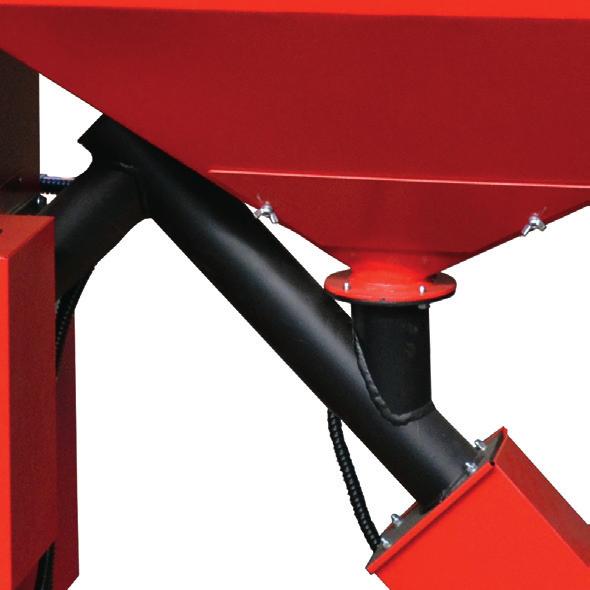
25 Possible malfunctions, First start-up 9.1 Fire prevention of the silo In the case that the boiler is not connected to a suitable flue gas system (not enough height, wrong diameter of the chimney, decreased diameter because of dirt or heavily polluted boiler), there is a possibility that fire spreads from the burner into the silo. Thermal valve Probe A part of the combustion air supply is led through the screw channel and thus prevents backfi re in the pellet silo. This air current is present at all times during operation. If the fl ue gas system is badly designed or heavily polluted, the air supply may not be enough to stop a backfire. In this case, the thermal valve is activated which releases tempering water if a temperature of 95 C or more is measured. The fi re is extinguished that way. The thermal valve and the probe are mounted on the boiler ex factory. The buyer is obligated to provide a water supply to the thermal valve (1/2 connection) and to comply with the prescriptions regarding dimension and quality of the fl ue gas system. If the flue gas system is designed incorrectly or heavily polluted or if the boiler is not cleaned regularly, the manufactorer is not liable for fire caused by such failures. Scheme of thermal valve 10 First start-up The first start-up of the boiler Biotec may only be carried out by a professional of the company STREBEL or an experienced installer. If the start-up is not carried out correctly, the boiler and the system can be damaged or destroyed or injury and material damage can occur. 9.2 Measures after thermal valve release 1.) Disconnect boiler from power supply. 2.) Remove screw and gear motor. 3.) Clean out damp pellets from the silo and the screw channel. 4.) Mount screw and gear motor. 5.) Remove residual water and dry damp system parts. Moisture can cause electrical shorts. 6.) Connect to power supply. If the damp pellets are not removed completely, screw and motor may jam. The manufactorer rejects responsibility and the guaranty expires if material damage occurs because of such failures Precautions for the fisr start-up 1.) Disconnect boiler from power supply. 2.) Check if the red main switch on the boiler side is activated. 3.) Check if the following parts are installed professionally and working. - All mechanical parts of the boiler, - burner and chamotte bricks, - fan, - circuit pump, - safety valve. 4.) Check of all electrical connections: - Correct installation of all electric components (gear motor, fan, controller, display), - Protection of unused connections, - ground, - power supply. 25
26 Disposal of the boiler, Guaranty 11 Disposal of the boiler 11.1 Removal The boiler removal must be carried out by qualified technicians. Otherwise, injury or material damage can occur. Procedure of the removal 1.) Stop boiler operation. 2.) Wait until the pellets in the burner room are burnt up and the boiler is cooled down. 3.) Disconnect the boiler from power supply. 4.) Disconnect the boiler from the rest of the heating installation with a turncock and drain the water from the boiler. 5.) Remove pellet silo. 6.) Remove boiler shell. 7.) Remove mineral wool insulation from the boiler body Disposal The steel parts of the boiler are delivered to a recycling centre: - Boiler body, - boiler shell, - pellet silo, - screw, - gear motor, - burner. The electrical parts as well as glas parts, mineral wool and plastic parts are seperately delivered to the recycling centre. The boiler parts must not be disposed in the domestic waste bin. 26
27 Terminal connections COMPENSATOR TANK PROBE NTC10K DOMESTIC WATER TANK NTC10K SCREW 230 VAC, 50 Hz, 50 W FAN 230 VAC, 50 Hz, 41 W IGNITION 230 VAC, 400 W ROOM THERMOSTAT RETURN RISER 230 VAC, < 500 W TANK CHARGER PUMP 230 VAC, < 500 W CIRCUIT PUMP 230 VAC, <500 W POWER SUPPLY 230 VAC, 50 Hz 3 x 1,5 mm 2 27

28 STREBEL customer service: Teleph. +43 (0) ,93,94 Fax +43 (0) Strebelwerk GmbH A Wiener Neustadt, Wiener Strasse 118 Teleph. +43 (0) Fax +43 (0) verkauf@strebel.at
TECHNICAL MANUAL BIOTEC 25 AND BIOTEC 40
 TECHNICAL MANUAL BIOTEC 25 AND BIOTEC 40 2 INDEX INDEX Safety information.......4 Technical data...5 Boiler features...6 Technical information........7 Fuel...... 8 Construction and function...... 9 Hydraulic
Operating Instructions
 Operating Instructions P4 Pellet 8-60 Read and follow the operating instructions and safety information. Subject to technical change. July 2009 Fröling Heizkessel- und Behälterbau Ges.m.b.H, Industriestrasse
INSTRUCTIONS FOR USE OF COMBINED BOILER INTENDED FOR COMBUSTION OF BOTH PELLETS AND SOLID FUEL ABC COMBO
 INSTRUCTIONS FOR USE OF COMBINED BOILER INTENDED FOR COMBUSTION OF BOTH PELLETS AND SOLID FUEL ABC COMBO .Technical specifications Boiler power DESCRIPTION Water content in a boiler Required draft Supply
INSTALLATION, OPERATION AND MAINTENANCE. Ariterm Vedo
 INSTALLATION, OPERATION AND MAINTENANCE Ariterm Vedo CONTENTS General...3 Installation...4-5 Laddomat 21 Connection diagram...6 Temperature control valve...7 About burning wood...8 Operation...9-11 Service
Electronic Pellet Burner Controller NPBC-V3M
 Electronic Pellet Burner Controller NPBC-V3M SOFTWARE VERSION 3.3a/3.2 page of 27 CHANGES IN THE USER MANUAL OR IN THE CONTROLLER'S SOFTWARE Version of the user manual Changes Page 2.2. The software version
USER MANUAL 9kW LILLY PELLET STOVE
 USER MANUAL 9kW LILLY PELLET STOVE Table of Contents.Overview of Stove Parts... 2.Technical Characteristics... 3 3.Important Information... 4 4.Pellet Specification...5 5.Technology... 6 6.Installation...
Electronic Pellet Burner Controller NPBC-V3-1
 Electronic Pellet Burner Controller NPBC-V3- SOFTWARE VERSION 3.2/3. page of 3 CHANGES IN THE TECHNICAL AND USER GUIDE OR IN THE SOFTWARE VERSION Technical and User Guide's version Changes Page 2.8. The
Heating with log wood
 English Heating with log wood De Luxe 18-40 Lambda 18-40 1 Competence is our success... HERZ FACTS: 60 subsidiaries Group headquarter in Austria Research & development in Austria Austrian owner 2.600 employees
Operating manual. Wood pellet boiler. PL M 15 and PL M 25
 Operating manual Wood pellet boiler PL M 15 and PL M 25 November 29, 2007 Important! This operating manual contains important information for the operator. The boiler must be professionally installed and
Heating with wood pellets kw
 Heating with wood pellets 0-60 kw Competence is our success... HERZ FACTS: 60 companies Group headquarter in Austria Research & development in Austria Austrian owner 2.600 employees in over 00 countries
Heating, Air Conditioning, Ventilation. Отопление-Кондиционеры-Вентиляция. MTM 8-30 kw UNIVERSAL OIL HEATER OPERATING MANUAL
 Heating, Air Conditioning, Ventilation Отопление-Кондиционеры-Вентиляция MTM 8-30 kw UNIVERSAL OIL HEATER OPERATING MANUAL 1. Usage MTM 8-30 universal oil heater is designed for heating commercial rooms
Installation, operation and care. Pellmax UB. Burner not included Replaces:
 Installation, operation and care Burner not included 2011-11-11 ver: Replaces: Contents 11.11 otes...3 General...4 Function...4 Technical data...5 System principle Pellmax with radiator and tank-in-tank
Boiler controller S-Tronic Plus
 Operating Instructions Boiler controller S-Tronic Plus Version 50.0 - Build 05.0 Translation of the original German operating instructions for technicians and operators Read and follow the instructions
Electronic pellet burner controller - NPBC-V3M. Electronic Pellet Burner Controller NPBC-V3M
 Electronic Pellet Burner Controller NPBC-V3M page 1 of 11 INTRODUCTION NPBC-V3M is an advanced, functionally completed controller for pellet burners. All the mechanisms and sensors of the burner, as well
SD2. Differential Controller. Operating and Installation Instructions F2 72.3
 SD2 Differential Controller Operating and Installation Instructions F2 72.3 i Please follow the safety information and read these Instructions carefully before putting the system into operation. Safety
WHE 2.24 / WHE 2.24 FF
 EN Wall-hung gas boilers WHE 2.24 WHE 2.24 FF User Guide 300011777-001-C . Contents 1 Introduction.............................................................................3 1.1 Symbols used...........................................................................................3
INSTALLATION, OPERATION AND MAINTENANCE. ARITERM SWEDEN AB Installation, Operation & Maintenance /28
 INSTALLATION, OPERATION AND MAINTENANCE ARITERM SWEDEN AB Installation, Operation & Maintenance - 2009.02.18-1/28 CONTENTS IMPORTANT INFORMATION 4 4 5 Notification to building authority Inspection Sweeping
Boiler Technical Specifications (2013)
") ACT Bioenergy Boiler Dimensions 0.5-0.85 Million Btu/h (150-250kW) Model CP500 CP600 CP750 CP850 Heat Output in MBtu/h (kw) 510 (150) 610 (180) 750 (220) 850 (250) Height ft (mm) 6 1 (1855) 6 1 (1855)
ACT Bioenergy Boiler Dimensions 0.5-0.85 Million Btu/h (150-250kW) Model CP500 CP600 CP750 CP850 Heat Output in MBtu/h (kw) 510 (150) 610 (180) 750 (220) 850 (250) Height ft (mm) 6 1 (1855) 6 1 (1855)
Forward-looking and energy effi cient Biomass heating
 English Forward-looking and energy effi cient Biomass heating 349-499 kw Large buildings Hotel complexes Housing estate projects 1 Competence is our success... HERZ FACTS: 50 companies Group headquarter
Remeha. Fuel oil/gas boilers P 520. Installation and Service Manual A
 Remeha Fuel oil/gas boilers EN Installation and Service Manual 300016859-001-A 63115 Declaration of conformity The appliance complies with the standard model described in declaration of compliance. It
INLINE СENTRIFUGAL FAN BOX BOX-R OPERATION MANUAL
 INLINE СENTRIFUGAL FAN BOX BOX-R OPERATION MANUAL CONTENT 3 Introduction 3 General 3 Safety rules 3 Storage and transportation rules 3 Manufacturer s warranty 4 Fan design 4 Delivery set 5 Technical data
High Performance Electronic Modulation Automatic Cleaning Easy Installation 4 Power Levels: 9,15,25,42kW. Pellet Boilers. Future of Ecological Heating
 Pellet Boilers High Performance Electronic Modulation Automatic Cleaning Easy Installation 4 Power Levels: 9,15,25,42kW Future of Ecological Heating Why choose an Ekoheat boiler? Ekopower is an innovative
BIOMASS BOILER ATTACK PELLET 30 AUTOMATIC PLUS
 BIOMASS BOILER ATTACK PELLET 30 AUTOMATIC PLUS W W W. A T T A C K. S K MODEL STRUC TURE OF THE AT TACK BOILERS THE NEW LINE OF ATTACK BOILERS FOR WOOD AND PELLETS 3000 000 6000 4 ATTACK FD PELLET yattack
INSTALLATION, OPERATION AND MAINTENANCE. Ariterm Hybrid 20
 INSTALLATION, OPERATION AND MAINTENANCE Ariterm Hybrid 20 TABLE OF CONTENTS General...3 Installation... 4-5 Dimensions - with flue gas exhauster...6 Dimensions - without flue gas exhauster...7 Pipe installations...8
IDE 20 / IDE 30 / IDE 50 IDE 60 / IDE 80
 IDE 20 / IDE 30 / IDE 50 IDE 60 / IDE 80 EN OPERATING MANUAL OIL HEATER TRT-BA-IDE20-30-50-60-80-TC-001-EN Table of contents Information on the use of this manual... 1 Scope of delivery... 1 General safety...
Operating instructions
 Operating instructions Capriz 2 24c 28c GB, IE Contents Contents 1 Safety... 3 1.1 Action-related warnings... 3 1.2 Intended use... 3 1.3 General safety information... 4 2 Notes on the documentation...
OPERATING INSTRUCTIONS with safety features
 Solid fuel boiler TKK3 with wood pellet burner TERMEC 70-90 KW OPERATING INSTRUCTIONS with safety features Prhova ka bb 22310 imanovci, Srbija Tel/Fax. +381 22 480404 +381 63 259422 oce@termomont.rs www.termomont.rs
1 DOCUMENT REVISION CONTROL ELEMENTS... 9
 CONTENTS Contents 1 DOCUMENT REVISION... 8 2 SOFTWARE VERSION... 8 3 BASIC DESCRIPTION... 8 4 CONTROL ELEMENTS... 9 4.1 BASIC DISPLAYS...10 4.2 CONTROL KEYS...11 4.2.1 Rotary button (Press / Turn)...11
HERZ ECO-Line Heating with logs or wood pellets
 English HERZ ECO-Line Heating with logs or wood pellets Lambda 18-40 10-60 1 Competence is our success... HERZ FACTS: 50 companies Group headquarter in Austria Research & development in Austria Austrian
Combined boiler. for solid fuel and pellets
 Combined boiler ATTACK WOOD&PELLET for solid fuel and pellets W W W. A T T A C K. S K MODEL STRUC TURE OF THE AT TACK BOILERS THE NEW LINE OF ATTACK BOILERS FOR WOOD AND PELLETS 3000 000 6000 4 ATTACK
SOUND-INSULATED FAN. Iso-K OPERATION MANUAL. Iso-K_v.1(2)-EN.indd :20:59
-EN.indd :20:59") SOUND-INSULATED FAN OPERATION MANUAL _v.1(2)-en.indd 1 10.08.2015 15:20:59 CONTENT Introduction 3 General 3 Safety rules 3 Transport and storage requirements 3 Manufacturer's warranty 3 Fan design 4 Delivery
SOUND-INSULATED FAN OPERATION MANUAL _v.1(2)-en.indd 1 10.08.2015 15:20:59 CONTENT Introduction 3 General 3 Safety rules 3 Transport and storage requirements 3 Manufacturer's warranty 3 Fan design 4 Delivery
Operating instructions
 The energy you need Operating instructions Betacom 3 24c -A (H-GB) 30c -A (H-GB) GB, IE Contents Contents 1 Safety... 3 1.1 Action-related warnings... 3 1.2 Intended use... 3 1.3 General safety information...
Solid fuel hot water boiler TKH KW INSTRUCTIONS MANUAL for usage and maintenance
 Solid fuel hot water boiler TKH 250-400 KW INSTRUCTIONS MANUAL for usage and maintenance Prhovacka bb 22310 Simanovci, Srbija Tel/Fax. +381 22 480404 +381 63 259422 oce@termomont.rs www.termomont.rs April
HEAT RECOVERY AIR HANDLING UNIT
 HEAT RECOVERY AIR HANDLING UNIT OPERATION MANUAL KOMFORT_L v2(2)_en.indd 1 07.08.2015 15:0:44 CONTENTS Introduction General Safety regulations Transportation and storage regulations Manufacturer's warranty
Operating instructions
 Operating instructions For the operator Operating instructions HOME SYSTEM GB, IE Publisher/manufacturer Vaillant GmbH Berghauser Str. 40 D-42859 Remscheid Tel. +49 21 91 18 0 Fax +49 21 91 18 28 10 info@vaillant.de
CentroPelet ZV14 TECHNICAL INSTRUCTIONS HEATING TECHNIQUE. for regulation, use and maintenance of pellet stove
 HEATING TECHNIQUE Centrometal d.o.o. - Glavna 12, 40306 Macinec, Croatia, tel: +385 40 372 600, fax: +385 40 372 611 TECHNICAL INSTRUCTIONS for regulation, use and maintenance of pellet stove CentroPelet
Boiler controller Lambdatronic S 3200
 Operating Instructions Boiler controller Lambdatronic S 3200 Version 50.04 - Build 05.04 Translation of the original German operating instructions for technicians and operators Read and follow the instructions
English. Efficiency. HERZ pellet boiler with condensing technology. ɳ over 106% COndEnSATiOn
 English HERZ pellet boiler with condensing technology Efficiency ɳ over 06% COndEnSATiOn 0-60 Competence is our success... HERZ FACTS: 0 companies Group headquarter in Austria Research & development in
Installation & Manual. Model T-25
 Installation & Manual TR Central Heating Stove With Solid Fuel Model T-25 Tested according to DIN EN 13240 For product efficiency and emission values, see the declaration of conformity! TABLE OF CONTENTS
Kyung Dong Oil Boiler. Contents. 1. General Warnings Safety Warnings
 Contents 1. General Warnings --------------------- 1 2. Safety Warnings ----------------------- 2 3. Parts and structure --------------------- 7 4. Safety Device ------------------------- 9 5. Checkups
TECHNICAL INSTRUCTIONS USE AND MAINTENANCE
 TECHNICAL INSTRUCTIONS USE AND MAINTENANCE Cm Pelet-set For boilers CentroPlus 25/35 and CentroPlus-B 25/35 (solid fuel and wood pellets fuel firing) TUPSCP-K-11-2016-ENG CONTENTS 1.Introduction 2. Status
USER MANUAL ACQUAHOME 32 B BLU
 USER MANUAL ACQUAHOME 32 B BLU Dear Customer, Thank you for preferring a T heating unit, a modern, high-quality product that is able to guarantee your maximum well-being for a long period of time, with
WOOD GASIFYING BOILER ATTACK DPX STANDARD / PROFI / LAMBDA INSTRUCTIONS FOR USE WWW. ATTACK.SK
 WOOD GASIFYING BOILER ATTACK DPX STANDARD / PROFI / LAMBDA INSTRUCTIONS FOR USE WWW. ATTACK.SK CONTENTS EN ATTACK DPX THE WOOD GASIFYING BOILER... 4 1 INTRODUCTION... 6 2 3 4 1.1 GENERAL DESCRIPTION...
ARITERM OY. Arimatic 500. User manual
 ARITERM OY Arimatic 500 User manual Table of contents 1. General information... 3 2. Transport, storage and package opening... 3 3. Warranty... 3 4. Installation and commissioning... 4 5. System description...
PELLET BURNER PV 350
 PELLET BURNER PV 350 INSTRUCTION MANUAL v1.1 1 PRODUCT DESCRIPTION...3 2 SAFETY RULES...3 3 WARNINGS...4 4 INSTALLATION INSTRUCTIONS...5 4.1 BOILER REQUIREMENTS...5 4.2 PELLET CONTAINER...6 4.3 INSTALLATION
INSTALLATION AND OPERATING INSTRUCTIONS BIOCLASS HM OD (FOR EXTERNAL USE)
") INSTALLATION AND OPERATING INSTRUCTIONS BIOCLASS HM OD (FOR EXTERNAL USE) Thank you for choosing a DOMUSA TEKNIK heating boiler. Within the product range offered by DOMUSA TEKNIK you have chosen BioClass
INSTALLATION AND OPERATING INSTRUCTIONS BIOCLASS HM OD (FOR EXTERNAL USE) Thank you for choosing a DOMUSA TEKNIK heating boiler. Within the product range offered by DOMUSA TEKNIK you have chosen BioClass
TAHITI CONDENSING KR 55 - KR 85
 IST 03 C 351-01 TAHITI CONDENSING KR 55 - KR 85 GB INSTALLATION USE AND MAINTENANCE Dear Customer, Thank you for choosing and buying one of our boilers. Please read these instructions carefully. They will
Installation and operation manual for pellet boiler TANGRA HP 30. Manufactured in accordance with standard: - EN Rev.
 Installation and operation manual for pellet boiler TANGRA HP 30 Manufactured in accordance with standard: - EN 303-5 Rev. 04-2014-03-28 User manual TANGRA HP30 - Rev. 04-2014-03-28 2 Content 1. Introduction...
Operating manual. Pellet boiler. Orlan Pellet ISO 9001
 Operating manual Pellet boiler Orlan Pellet ISO 9001 Contens 1. Boiler s use...................................................................... 3 2. Boiler s way of working...........................................................
USERS MANUAL FOR GAS BOILERS
 USERS MANUAL FOR GAS BOILERS PLEASE READ THE MANUAL CAREFULLY: IT CONTAINS IMPORTANT INFORMATION REGARDING SAFETY, INSTALLATION, USE AND MAINTENANCE OF THE APPLIANCE MODELS: NOVADENS 24 NOVADENS 24C NOVADENS
Operating Manual PELLEMATIC PES CMP06 TO_VA6.39 Pelletronic TOUCH ENGLISH. PE 1491 EN_TO 1.0 Europe s specialist in pellet heating
 Operating Manual PELLEMATIC PES 12 56 CMP06 TO_VA6.39 Pelletronic TOUCH ENGLISH PE 1491 EN_TO 1.0 Europe s specialist in pellet heating Title: Operating manual PES 12-56 Article number: PE 1491 EN_TO 1.0
Smart Smart IR. Service instruction SALES DATE MANUFACTURED ON (DATE): APPROVAL MARK SOLD. model (check applicable) is recognized as serviceable
: APPROVAL MARK SOLD. model (check applicable) is recognized as serviceable") Smart Smart IR model (check applicable) is recognized as serviceable Service instruction SALES DATE MANUFACTURED ON (DATE): SOLD APPROVAL MARK SMART-EN-04 BLAUBERG Company is happy to offer your attention
Smart Smart IR model (check applicable) is recognized as serviceable Service instruction SALES DATE MANUFACTURED ON (DATE): SOLD APPROVAL MARK SMART-EN-04 BLAUBERG Company is happy to offer your attention
Planning and installation guide HDG Compact 50/65 with HDG Hydronic
 Planning and installation guide HDG Compact 50/65 with HDG Hydronic HDG Bavaria GmbH November 2006 HDG Compact - Version - en Planning and installation guide HDG Compact - Content Content Notes on this
User Manual GV25 GV35 GV702. Company information: Original instructions GV12066 (1)
") User Manual Original instructions GV25 GV35 GV702 Company information: www.vipercleaning.eu info-eu@vipercleaning.com GV12066 (1) 2012-04-10 USER MANUAL ENGLISH TABLE OF CONTENTS Introduction... 4 Manual
User Manual Original instructions GV25 GV35 GV702 Company information: www.vipercleaning.eu info-eu@vipercleaning.com GV12066 (1) 2012-04-10 USER MANUAL ENGLISH TABLE OF CONTENTS Introduction... 4 Manual
JT-SB116JH-G-NA JT-SB116JH-W-NA
 1311875HF4503 Hand dryer MODEL JT-SB116JH-G-NA JT-SB116JH-W-NA Unit color -G (Grey), -W (White) Model Name Display Position. Power voltage display position. INSTRUCTION MANUAL For User Read this manual
INSTALLATION AND OPERATING INSTRUCTIONS. Ariterm 60+
 INSTALLATION AND OPERATING INSTRUCTIONS Ariterm 60+ CONTENTS General.... 2 Installation.... 4-5 Installation of temperature limit valve... 6 Measurements and connections... 7 Technical specifications and
Forced draught gas burner
 Installation, use and maintenance instructions Forced draught gas burner Code Model Type 3751982 GAS 3 519T80 291 (3) - 02/2010 DECLARATION Declaration of conformity in accordance with ISO / IEC 17050-1
ST 53.1 User s manual
 Tech - 1 - ST 53.1 User s manual Table of contents I. Safety... 3 II. Description... 4 III. Installation... 4 IV. Operating the Controller... 6 IV.a) Principle of Operation... 6 IV.b) Control... 6 V. Controller
1. GENERAL SAFETY RULES
 ID180 & ID290 Indirect-Fired Diesel/Oil Construction Heaters Sure Flame Products Lethbridge, Alberta, Canada Telephone: (403)328-5353 Fax: (403)328-9956 www.sureflame.ca July 12, 2006 Service and Maintenance
Main components. Buying all components from same manufacturer or reseller it guarantees better compatible and service if something happens
 Main components The bigger the need of heat output is. the bigger the components (storage. boiler. chimney etc.) In private houses the output need of the boiler is about 25 40 kw and in farms from 60 kw-
INSTRUCTION MANUAL & SERVICE MANUAL ORLIGNO 400
 INSTRUCTION MANUAL & SERVICE MANUAL ORLIGNO 400 Content 1. Delivery......................................................................... 3 2. Installation and assembly.........................................................
Operating Manual JuniorPower
 To be read completely before start-up! Operating Manual JuniorPower 12/04 von Oertzen GmbH Ferdinand-Harten-Str. 10 22949 Ammersbek Tel. +49 40 604110 Fax +49 40 6041149 www.oertzen-gmbh.de info@oertzen-gmbh.de
INSTALLATION AND OPERATING INSTRUCTIONS BIOCLASS HM
 INSTALLATION AND OPERATING INSTRUCTIONS BIOCLASS HM Thank you for choosing a DOMUSA TEKNIK heating boiler. Within the product range offered by DOMUSA TEKNIK you have chosen BioClass HM model. With a suitable
BG2000S PRE-MIX GAS BURNER
 BG000S PRE-MIX GAS BURNER INSTALLATION OPERATION & MAINTENANCE DOCUMENTATION STOKVIS ENERGY SYSTEMS 96R WALTON ROAD EAST MOLESEY SURREY KT8 0DL TEL: 08707 707 77 FAX: 08707 707 767 E-MAIL:info@stokvisboilers.com
Operating instructions
 Operating instructions For the operator Operating instructions ecotec plus Gas-fired wall-hung high-efficiency boiler GB, IE Publisher/manufacturer Vaillant GmbH Berghauser Str. 40 D-42859 Remscheid Telefon
Illustration shows item no Z Original operating manual. Operating manual. BlueMobil 60. Item no: Z-3285
 Operating manual BlueMobil 60 Item no: Z-3285 Original operating manual Illustration shows item no Z-3285 Important Copyright It is essential that you read this manual thoroughly before the initial operation
Operating Instructions
 Operating Instructions S3 Turbo Be sure to read and comply with the operating instructions and safety information Subject to technical change. Fröling Heizkessel- und Behälterbau Ges.m.b.H, Industriestrasse
Archive. LC2200 Level Controller. 1. Safety information. 2. General product information. 3. Installation. 4. Setting up the controller
 4025250/10 IM-P402-77 AB Issue 10 LC2200 Level Controller Installation and Maintenance Instructions 1. Safety information 2. General product information 3. Installation 4. Setting up the controller 5.
T UNI 7000 F. Operating instructions For the user (2006/05) AU/GB
 AU/GB") 6 720 648 662-00.1T UNI 7000 F Operating instructions For the user AU/G 2 Contents Contents Contents 2 1 Safety information and explanation of symbols 3 1.1 For your safety 3 1.2 Explanation of symbols
6 720 648 662-00.1T UNI 7000 F Operating instructions For the user AU/G 2 Contents Contents Contents 2 1 Safety information and explanation of symbols 3 1.1 For your safety 3 1.2 Explanation of symbols
AXIS-QA G TUBO-M/MZ AXIAL FANS. Axis / Tubo OPERATION MANUAL
 TUBO-M/MZ AXIS-QA AXIS-Q TUBO-F AXIS-QR AXIS-F AXIS-QRA AXIS-QA G AXIAL FANS EN OPERATION MANUAL www.blaubergventilatoren.de CONTENT 3 Introduction 3 General 3 Safety rules 3 Transport and storage requirements
SOTTOSTAZIONI PER TELERISCALDAMENTO DISTRICT HEATING SUBSTATIONS
 SOTTOSTAZIONI PER TELERISCALDAMENTO DISTRICT HEATING SUBSTATIONS INDEX Ed. 20150422 GENERAL INFORMATION... 2 Before installing... 2 Materials and PED (97/23/CE) Standards... 3 SKID-TYPE DISTRICT HEATING
Laddomat. Mixing valves for solid fuel boilers. Version 1.01
 Laddomat Mixing valves for solid fuel boilers Version 1.01 Laddomat > Mixing valves for solid fuel boilers Why Laddomat This is the answer to those who burn wood or pellets and wonder why you should complement
So old fashioned... As the combustion chamber is completely room sealed, it does not release any smells and does not dirty.
 ARREDO E BENESSERE So old fashioned... An intelligent choice When on a cold winters night the warm glowing flames of the KALDUS boiler are there to welcome you back home, you will be pleased that you decided
ENERGY TOP. Condensing boiler solutions
 ENERGY TOP Condensing boiler solutions 1 ENERGY TOP > ENERGY TOP RANGE A wide array of flexible solutions both for centralised residential application and big commercial plants The increasing need for
E-COMBI EVO E-SYSTEM EVO
 E-COMBI EVO E-SYSTEM EVO User s manual CONDENSING WALL-HUNG GAS BOILER G.C.N.:47-116-68 (24 kw) G.C.N.:47-116-69 (30 kw) G.C.N.:47-116-70 (38 kw) G.C.N.:41-116-39 (24 kw) G.C.N.:41-116-40 (30 kw) Country
Service Settings. EASY PFA Universal Biomass Heating System Controller. Technical Documentation
 Service Settings EASY PFA Universal Biomass Heating System Controller Technical Documentation Safety Precautions Caution! Schock Hazard! Risk of electrical schock which may cause serious injuries or death.
Illustration shows item no Z Original operating manual. Operating manual. BlueMobil eco. Item no: Z-3278
 Illustration shows item no Z-3278 Operating manual BlueMobil eco Item no: Z-3278 Original operating manual Important Copyright It is essential that you read this manual thoroughly before the initial operation
Installation & Operating Manual ZM kW Universal Oil Heater. ZMH Ltd t/a Z M Heaters T (0)
") Installation & Operating Manual ZM-130 16 32kW Universal Oil Heater OVERVIEW Dfdfdfdsfd Dfdfffdfdf Dfdfdf 4 1. Overheat thermostat 2. Combustion chamber lid 3. Oil feed line 4. Activation thermostat 5.
Installation & Operating Manual ZM-130 16 32kW Universal Oil Heater OVERVIEW Dfdfdfdsfd Dfdfffdfdf Dfdfdf 4 1. Overheat thermostat 2. Combustion chamber lid 3. Oil feed line 4. Activation thermostat 5.
Induction Fryer. Instruction manual. Model Modèle Modell Modello Modelo Malli: CP793
 Induction Fryer Instruction manual Model Modèle Modell Modello Modelo Malli: CP793 UK Safety Tips Position on a flat, stable surface. A service agent/qualified technician should carry out installation
Biomass Pellet Boilers
 Biomass Pellet Boilers simplicity, modern design and technological perfection biomass green energy Quality doesn t have to cost the earth KOVAN Ekoline with its headquarters in Gračanica (BIH) where the
English. Heating with logs & wood pellets 20-40
 English Heating with logs & wood pellets 20-40 1 Competence is our success... HERZ FACTS: 60 subsidiaries Group headquarter in Austria Research & development in Austria Austrian owner 2.600 employees in
wc431 Slimline Integrated Dishwasher Manual for Installation, Use and Maintenance
 wc431 Slimline Integrated Dishwasher Manual for Installation, Use and Maintenance Contents Contents... 2 Important... 3 Important Notes... 4 Recommendations... 5 Before First Use... 5 Control Panel...
Cookshack, Inc. Model FEC100 Fast Eddy Oven. Version /1/10
 Cookshack, Inc. Model FEC100 Fast Eddy Oven Operator s Manual Please read this entire manual installation and use of this pellet fired smoker oven. Failure to follow these instructions could result in
USE AND MAINTENANCE. Cm Pelet-set TECHNICAL INSTRUCTIONS. (14-35 kw) For boilers: EKO-CK P (EKO-CK 20-40) EKO-CKB P (EKO-CKB 20-40)
 For boilers: EKO-CK P (EKO-CK 20-40) EKO-CKB P (EKO-CKB 20-40)") TECHNICAL INSTRUCTIONS USE AND MAINTENANCE Cm Pelet-set (14-35 kw) For boilers: EKO-CK P 20-40 (EKO-CK 20-40) EKO-CKB P 20-40 (EKO-CKB 20-40) TUPS-K-02-2011-E-N-ENG CONTENTS 1. Introduction....... 2. Status
TECHNICAL INSTRUCTIONS USE AND MAINTENANCE Cm Pelet-set (14-35 kw) For boilers: EKO-CK P 20-40 (EKO-CK 20-40) EKO-CKB P 20-40 (EKO-CKB 20-40) TUPS-K-02-2011-E-N-ENG CONTENTS 1. Introduction....... 2. Status
INSTALLATION AND OPERATING INSTRUCTIONS. Ariterm Biomatic+ 20
 INSTALLATION AND OPERATING INSTRUCTIONS Ariterm Biomatic+ 20 TABLE OF CONTENTS GENERAL INFORMATION General information... 2 Transport, storage and package opening... 2 Technical data... 3 Functional description...
MW001 Integrated Dishwasher. Manual for Installation, Use and Maintenance
 MW001 Integrated Dishwasher Manual for Installation, Use and Maintenance Important The CDA Group Ltd cannot be held responsible for injuries or losses caused by incorrect use or installation of this product.
USE AND MAINTENANCE. Cm Pelet-set (60-90 kw) TECHNICAL INSTRUCTIONS
 TECHNICAL INSTRUCTIONS") CENTROMETAL d.o.o. Glavna 12 40306 Macinec Croatia tel: +385 40 372 600; fax : +385 40 372 611 TECHNICAL INSTRUCTIONS USE AND MAINTENANCE Cm Pelet-set (60-90 kw) For boilers: EKO-CK P 70-110 TUPS-90K-09-2015-E-N-eng
CENTROMETAL d.o.o. Glavna 12 40306 Macinec Croatia tel: +385 40 372 600; fax : +385 40 372 611 TECHNICAL INSTRUCTIONS USE AND MAINTENANCE Cm Pelet-set (60-90 kw) For boilers: EKO-CK P 70-110 TUPS-90K-09-2015-E-N-eng
/2010 US/CA
 6 720 646 148-11/2010 US/CA (en) For the user User s Instructions Condensing gas boiler Logamax plus GB162-L.B. 80 kw/100 kw Please read thoroughly before operating This manual is available in the English
Wood logs boiler with a gasication eect IGNIS KW. INSTRUCTIONS MANUAL for usage and maintenance
 Wood logs boiler with a gasication eect IGNIS 20-40 KW INSTRUCTIONS MANUAL for usage and maintenance Prhovacka bb 22310 Simanovci, Srbija Tel/Fax. +381 22 480404 +381 63 259422 oce@termomont.rs www.termomont.rs
Heating with wood chips
 Heating with wood chips YOUR RELIABLE PARTNER Present years on the market 110 for over 20-60 Our success is our expertise... HERZ-Armaturen Ges.m.b.H The company Founded in 1896, HERZ has had an ongoing
Instruction Manual. Electronic gas and smoke detector GRM
 Mess-, Regel- und Überwachungsgeräte für Haustechnik, Industrie und Umweltschutz Lindenstraße 20 DE-74363 Güglingen Telefon +49(0)7135-102-0 Service +49(0)7135-102-211 Telefax +49(0)7135-102-147 E-Mail
HIGH POWER. VICTRIX PRO 2 ErP. High power, wall-hung condensation boiler
 HIGH POWER VICTRIX PRO 2 ErP High power, wall-hung condensation boiler MAIN INDEX INDEX 1 VICTRIX PRO 35-55 2 ErP SPECIFICATIONS...5 2 VICTRIX PRO 80-100-120 2 ErP SPECIFICATIONS...6 3 VICTRIX PRO 35-55
ELECTRIC BOILERS FOR CENTRAL HEATING
 ELECTRIC BOILERS FOR CENTRAL HEATING TermoMax INSTRUCTIONS FOR INSTALLATION INSTRUCTIONS FOR INSTALLATION We reserve the right of alternations WE ARE NOT LIABLE FOR DAMAGES RESULTING FROM NON- OBSERVING
Glass and Dishwashers. BarAid 500/800. Installation and. Starting from Serial No.:
 Glass and Dishwashers BarAid 500/800 Installation and operation Instructions Starting from Serial No.: 8652 0001 REV. 19.01.2009 1617-A-01-09 Content Page 1 Important Notes... 4 2 Installation... 5 2.1
Installer manual AG-WL10
 LEK LED CLEAN TIMER OPERATION Installer manual Indoor unit air/air heat pump IHB GB 1637-1 331827 Table of Contents 1 Important information Safety information Read before starting the installation Electrical
Cooker Hood Instruction Manual
 Cooker Hood Instruction Manual Model number(s): RHSCH601SS/B & RHSCH901SS/B IMPORTANT: RETAIN FOR FUTURE REFERENCE Contents Safety Instructions. 3-6 Product Overview. 7 Positioning. 8 Operational modes.
Installation, operation and care Firewood boiler Vedolux 40 UB
 Installation, operation and care Firewood boiler Vedolux 40 UB 2008-09-23 Ver 2 Replaces: 05-11 VEDOLUX 40 UB Notes 0809 To be completed when the Vedolux 40 UB is installed Serial number:... Installation
BarAid 400. Installation and. Starting from Serial No.:
 Glasswasher BarAid 400 Installation and operation Instructions Starting from Serial No.: 8649 1065 REV. 19.01.2009 DE 1618-A-01-09 Content Page 1 Important Notes... 4 2 Installation... 5 2.1 Location...
ETA PE-K. The pellet boiler with technology that's built to last, for larger heating needs. 35 to 90 kw. A passion for perfection.
 ETA PE-K ETA PE-K The pellet boiler with technology that's built to last, for larger heating needs. 35 to 90 kw A passion for perfection. www.eta.co.at ETA PE-K Pellet heating for domestic and commercial
DEVRON SERIES MULTI FUEL FIRED GASIFICATION HOT WATER BOILERS DEVRON-30, DEVRON-40 OPERATION, USE AND MAINTENANCE MANUAL
 DEVRON SERIES MULTI FUEL FIRED GASIFICATION HOT WATER BOILERS DEVRON-30, DEVRON-40 OPERATION, USE AND MAINTENANCE MANUAL Rev A: JUNE 2017 INDEX 1- INTRODUCTION... 3 2- WARNINGS... 3 3- DECLARATION OF CONFORMITY...