Multiflow Liquid-Coupled System SUPPLEMENT TO OPERATION MANUAL
|
|
|
- Amie Holland
- 5 years ago
- Views:
Transcription


1 Multiflow Liquid-Coupled System SUPPLEMENT TO OPERATION MANUAL
2 Table of Contents CAIRplus NOTICE! This supplement to operation manual is not a substitute of the operation manual! Use the current supplement only in conjucntion with the main operation manual for the CAIRplus unit and consider all specified safety notices! 1 Safety and User Instructions Icons and safety notices used in this manual Proper use Technical description and data Scope of performance of the high-performance liquid-coupled heat exchanger Multiflow Additional mounting parts Control cabinet Shipping and storage Transport Assembly On-site performances Install heat exchanger pipework Commissioning Requirements Commissioning Procedure Servicing and maintenance Servicing and cleaning Maintenance Dismantling and Disposal Dismantling Disposal Appendix FläktGroup DC GB /R2 Subject to modifications
3 CAIRplus Safety and User Instructions 1 Safety and User Instructions Read the Safety Notice in the Operating Manual CAIRplus and comply with it! 1.1 Icons and safety notices used in this manual The following icons are used to highlight particular text sections in this operation manual: This symbol is used to indicate normal lists. This symbol indicates handling instructions. This symbol indicates the result of an action. NOTICE! This symbol denotes additional instructions on using the unit. The following names/icons are used to designate safety notices: HAZARDOUS VOLTAGE! This symbol indicates a risk of electric shock when working on the equipment. PERSONAL INJURY! This section specifies procedures and precautions for the prevention of personal injury. HIGH PRESSURE HAZARD! This section specifies procedures and precautions for the prevention of personal injury due to high pressure. ENVIRONMENTAL DAMAGE! This section specifies procedures and precautions for preventing environmental damage with reference to the valid national regulations on environmental protection. DAMAGE TO THE UNIT! This section specifies procedures and precautions regarding the prevention of equipment damage. 1.2 Proper use The Multiflow integrated recycling systems provide the heat recovery within the CAIRplus air handling units. It permits the heat and/or cold supply in the brine circuit. Improper use Any use other than that described above is considered improper. If necessary, check if your CAIR unit is suitable for your intended purpose and application. The manufacturer/supplier is not liable for any damages arising from improper use. The user alone bears the risk. FläktGroup DC GB /R2 Subject to modifications 3

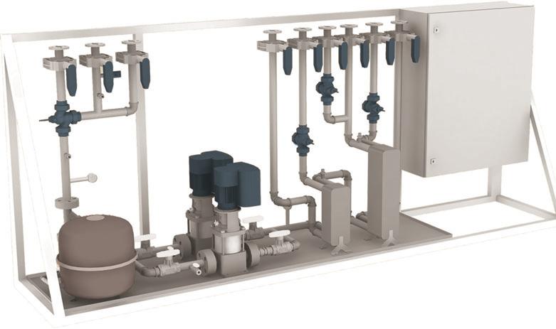
4 Technical description and data CAIRplus 2 Technical description and data 2.1 Scope of performance of the high-performance liquid-coupled heat exchanger Multiflow Fig. 2-1: CAIRplus and hydraulic assembly High-performance liquid-coupled system for heal and cold recovery Thermodynamically optimized heat exchangers with high counterflow exposure ensure a maximum degree of transmission between media. Exact proportion of the brine volume is regulated by the frequency-controlled circulating pumps and is decisive for high efficiency levels. The highest heat recovery rates can be achieved with the same heat flows on the air and brine side. Temperature changes in the brine flow, supply air and return air flows are then as a rule of the same proportion.the control system regulates air and water-side temperatures as well as the pump to achieve maximum energy recovery rate. Supply air Outdoor air M Chilled water pump M Pumped warm M M Extract air Exhaust air 4 FläktGroup DC GB /R2 Subject to modifications
5 CAIRplus Technical description and data Technical benefits Transmission of germs, pollutants and offensive odors is prevented Separated air ducts offer significant optimization potential during the layout stage of the air ventilation system. As a result, enhanced explosion and fire protection can be achieved. Great operational reliability of the unit results in reduced maintenance costs The finned overall depth of each heat exchanger meets the standards stipulated by VDI 3803, VDI 6022, DIN 1946, DIN EN and enables most thorough cleanability Regulation anti-freeze Protection Anti-icing control for maintaining the maximum possible energy recuperation. Return air temperature and humidity make it possible to determine the dew point of the current air condition. If the outdoor-air temperature is within the freezing range, the 2-way valve (SV1) is used to adjust the brine temperature to the dew point temperature of return air before it enters the return-air heat exchanger. Through exact measuring of the dew point, energy recovery can be even better utilized at low brine temperatures rather than in situations where conventional medium temperature-dependent anti-icing control would be applied. Option: Adiabatic humidification of return air (indirect evaporative cooling) for the minimization of mechanical cooling in summer operating mode. Possibility to feed both heating and cooling energy into the brine circuit of the energy-recovery system using a water/brine plate heat exchanger Hydraulic module for inside installation Frame construction with an integrated tray for fixation of hydraulic components. The frame is galvanized and additionally painted in RAL Built-in components are properly retained by rubber clips on the frame construction. Pipework for supply-air, return-air, as well as coil connections are located on the upper side of the pump assembly group. Connections with threading or flange PN 16. Servicing and operation shall be performed on one side. All fittings are suitable for water/glycol mixture with 25 to 30% concentration. Option: Installed in unit empty chamber for indoor and outdoor installation. Pump: Vertical, standard-suction centrifugal pump with oppositely arranged suction and pressure nozzles of the same diameter (inline model). Pump hydraulic system includes a base piece, head piece with corrosion-proof cataphoretic dip painting and stainless-steel wheel sets with float-mounted Teflon split rings. Head and base pieces are connected together through stay bolts and a stainlesssteel pump casing. Motor and pump shaft are connected together with a balanced sleeve coupling. Maintenance-friendly, highly wear-resistant mechanical cartridge seal can be replaced from the outside (material combination SiC/SiC). Motor for pump CRE 5-5 and CRE 10-3: The pump is equipped with a 3-phase, fan-cooled permanent magnet synchronous motor. For speed regulation, the motor has a frequency converter and PI controller accommodated in the terminal box of the motor. The electronic speed regulation permits a continuous adaptation of the motor speed so that the pump capacity always meets the current requirements. The motor with associated frequency converter surpasses the efficiency requirements of the highest energy efficiency class IE4 (Super Premium Efficiency), which are specified in the IEC output 1 (CD). FläktGroup DC GB /R2 Subject to modifications 5
6 Technical description and data CAIRplus Motor for pump CRE 15-2 and CRE 15-3: Surface-cooled 3-phase electric motor of efficiency rating IE 3 with an integrated frequency inverter. Motor and electronics are furnished with an integrated overload and temperature protection, an external motor protection is not required. Pump: CRE 5-5 A-FGJ-A-E CRE 10-3 A-FJ-A-E CRE 15-2 A-F-A-E CRE 15-3 A-F-A-E Shaft seals Inspection notices on the unit identification plate Characteristics tolerance Pump casing material HQQE CE, TR ISO 9906: 1999 Annex A Cast iron, EN-JL 1030, ASTM A48-30 B Rotor material Stainless steel, DIN W.-Nr , AISI 304 Rotor material C Max. Pressure at preselected temperature 25 bar at120 C 25 bar at-20 C 16 bar at 120 C 16 bar at -20 C Connection DIN W.-No Nominal diameter DN 25/DN 32 DN 40 DN 50 Rated pressure bar PN 16/PN 25 PN16 Flange size of the motor FT115 FT130 Type of the motor 90SC 90LD 100LC 112MC Motor rated output P2 kw 1,5 2,2 3 4 Network frequency Hz Rated voltage 3 x x Rated current A Performance factor Cos phi Nominal speed 1/ min Efficiency % 88,0 89,0 87,1 88,1 Efficiency class (IEC Edition 1 (CD)) IE4 IE3 Protection class(iec 34-5 Insulation class (IEC 85) Tab. 2-1: Pump data IP55 F Option: Two parallel-switched pumps for redundant operation including non-return valves and shut-off device. 2.2 Additional mounting parts Diaphragm pressure expansion vessel for closed cooling water systems (built according to DIN 4807, approval according to EU Pressure Device Directive 97/ 23/EG) Foot design for fixation. Pre-pressure 6 bar Quick coupling for diaphragm pressure expansion vessels in closed-circuit cooling water installations. Equipped with a shut-off mechanism secured against inadvertent closing and a draining device to comply with DIN EN 12828, certified by TÜV. Pressure gauge is mounted before and after pump. Spring-tube measuring system DIN EN 837-1, steel casing, display range 0 to 6 bar, bottom connection G ¼, medium-carrying brass components Diaphragm safety valve, certified and type-tested, spring-loaded, for closed-circuit hydraulic installations, actuation overpressure 6 bar 6 FläktGroup DC GB /R2 Subject to modifications

7 CAIRplus Technical description and data On-site removal or retainer device for an inadvertent possible discharge of water/ glycol mixture from the valve or into the catch basin. Version according to Water Resources Law. Isolating valves attached before and after pump, with hand wheel or hand lever, with maintenance-free spindle seal Emptying and filling armature, with socket wrench set and loose square wrench with closure cap Shut-off ball valves/dampers attached at the supply and return line of the external energy supply, intake and exhaust air heat exchanger, for water/glycol with hand wheel or hand lever, with maintenance-free spindle seal. Dirt traps, Y-shaped, overall length DIN EN with normal sieve, threaded hole and closure stoppers in the cleaning closure Pressure sensor for monitoring the min. pressure with electrical output signal in the switch cabinet Fig. 2-2: Diaphragm pressure expansion vessel V n Nominal volume/liter Weight [kg] Ø D [mm] H [mm] h [mm] A 6 bar/120 C N 50 12, R¾ N 80 17, R1 N , R1 N , R1 N , R1 Tab way valve with drive for anti-icing protection regulation (SV1) PN 16, basic body made of cast iron and casing made of plastic, cones made of brass, spindle made of non-rusting steel, spindle seal with double O-ring made of EPDM, electric servo drive, actuating signal 0 (2) to 10 V, with switch for end position notification, with mechanical manual adjustment. Option: Actuator and drive are assembled, valve tightly closing in the end position, automatic self-calibration for commissioning, signal processing with a non-wearing path-measuring system by means of Hall sensor, mechanical position indication Water/glycol plate heat exchanger made of stainless steel for warming the brine circuit in heating operation 2-way valve (SV3) for the regulation of the input heating output with drive, PN 16, casing made of cast iron, with primer, cone made of brass, spindle made of nonrusting steel, material No , spindle seal with double O-Ring made of EPDM, electrical servo drive, supply voltage 24 V DC, actuating signal 0 (2) to 10 V, with switch for end position notification, with mechanical manual adjustment, actuator and drive are assembled, with mechanical position indication On the building side it must be ensured that the heating medium is available without delay. FläktGroup DC GB /R2 Subject to modifications 7

8 Technical description and data CAIRplus Option: Water/glycol plate heat exchanger made of stainless steel cooling the brine water quantity in cooling operation 2 way-valve (SV4) for the regulation of the input cooling capacity with drive, PN 16, casing made of cast iron, with primer, cone made of brass, spindle made of nonrusting steel, material No , spindle seal with double O-Ring made of EPDM, electrical servo drive, supply voltage 24 V DC, actuating signal 0 (2) to 10 V, with switch for limit position message with mechanical manual adjustment, assembled actuator and drive, with mechanical position indication. 3-way valve (SV2) for bypassing the exhaust air heat exchanger, PN 16, casing made of cast iron, cone made of brass, spindle made of non-rusting steel, spindle seal with double O-Ring made of EPDM, electrical servo drive, supply voltage 24 V DC, actuating signal 0 (2) to 10 V, with switch for end position notification, with mechanical manual adjustment, assembled actuator and drive, tightly closing valve in the end position, automatic self-calibration for commissioning, signal processing by a non-wearing path-measuring system by means of Hall sensor, mechanical position indication. On the building side, it should be ensured that the cooling medium is available without delay Dimensions of the pump module Fig. 2-3: Pump module Pipe nominal size Heat supply Cold supply Length [mm] Width [mm] Height [mm] Water capacity [l] DN32/DN DN32/DN40 X DN32/DN40 X DN32/DN40 X X DN50/DN DN50/DN65 X DN50/DN65 X DN50/DN65 X X Control cabinet The switch cabinet is fitted to the hydraulics module and wired with all attached field equipment at the pump assembly; the standard door stop is on the right. You will find more information in the separate Operating Manual Control and Monitoring System Multiflow. 8 FläktGroup DC GB /R2 Subject to modifications
9 CAIRplus Shipping and storage 3 Shipping and storage 3.1 Delivery The unit is delivered in individual delivery units. The delivery is done on shipping pallets. When the unit is delivered, check that the shipment is correct according to the despatch note, and also check for completeness. NOTICE! Consider instructions relating to the procedures in case of shipping damage provided on the unit packaging or in despatch documents! What steps should you should take in the event of shipping damage? The exterior of the packaging is damaged 1 Unpack the equipment in the presence of the truck driver and have him confirm the damage on the shipping order. 2 Inform the FläktGroup Sales Company immediately. Exterior packaging is O.K., contents are damaged. 1 Once you have established the extent of the damage, report the damage to the FläktGroup Sales Company in writing. 2 Take photographs of the damaged parts. 3 Possible shipping damage must be reported no later than 4 days after delivery. It will not be possible to process claims if the above-mentioned points are not fulfilled. In both cases, consult the FläktGroup Sales Company installing the units. 3.2 Transport NOTICE! Transport the unit only in its original packing. Remove the original packaging only just before installation. For shipping and rigging the FläktGroup unit use the lifting lugs or lifting points provided by the manufacturer. For safety reasons, protective clothing when lifting or transporting the unit. DANGER OF OVERHEAD LOADS! Never stand beneath suspended loads, since there is always a risk that the lifting gear, tackle, ropes or slings are faulty or damaged. Failure to follow safety precautions could result in death or serious injury. Before lifting or shipping the unit, make sure that all doors, dampers and panels are fixed and secured. Only use lifting gear with sufficient load-bearing capacity. Never use damaged lifting equipment. Ropes/chains must not be knotted and/or be exposed to sharp edges. Only use ropes/chains of the same length. Move the unit carefully without jerky movements. Do not set the unit down abruptly or bump it. FläktGroup DC GB /R2 Subject to modifications 9
10 Shipping and storage CAIRplus Shipping with a (folk) lift truck On shipping, always use the supplied pallet as a supporting surface. Verify proper center of gravity lift point and uniform distribution of weight. 3.3 Storage NOTICE! If you store the components, observe the permissible storage conditions. Remove the original packaging only just before installation. Up to commissioning, protect the components from building dust and dirt as well as from damages! If components were delivered without packaging, then they must be protected from building dust and dirt by suitable measures until commissioning. If packing takes place on site by others, make sure that condensate cannot form below the packaging (consider relevant clearance between the packaging and casing). Always place components on a level surface for storage or interim storage! Protect components against bumps and knocks to avoid damages. Air temperature 0 C to +50 C Allowable storage conditions / allowable air condition for non-installed units Air humidity Store units in a dry, non-condensing atmosphere DAMAGE TO THE UNIT! Ensure that the pump modules are stored frost-free, since residual water might be in the pipes. 10 FläktGroup DC GB /R2 Subject to modifications
11 CAIRplus Assembly 4 Assembly NOTE ON ASSEMBLING AND INSTALLING THE UNIT! Here you will find information on how to assemble and install the unit. Placement, installation and assembly must only be carried out by qualified licensed staff or other individuals with proper professional training and experience in the relevant accident prevention regulations, as well as other generally recognized safety and occupational health codes. NOTICE ON MOVING THE UNIT! If the units have been moved from one plant/location to another, repeated commissioning is required. Refer to the description in the chapter "Commissioning". 4.1 On-site performances Pipework of the air-side heat exchanger (supply air/extract air) between each other Pipework between hydraulic assembly and the air-side heat exchangers (supply air/ extract air) The nominal pipe size of the heat exchangers can deviate from the nominal width of the pump module. For the pipework, the nominal pipe size of the pump module is recommended. The pump module may not be burdened by the weight of the external pipework For integrated heat input, the pipework between the hydraulic assembly and the external heat generator (network) (water inlet/return line) For integrated refrigeration supply, the pipework between the hydraulic assembly and the external heat generator (network) (water inlet/return line) Proper leakage test, filling and venting of the system (including filling with predetermined ethylene-glycol ratio (Antifrogen N)) Sufficient venting of the heat exchanger is only possible for greater flow possibilities Insulation of all on-site piping systems for the HCR system Wiring (including attachment in the HCR switch cabinet) of all required sensors and the supply lines at the HCR switch cabinet. Corresponding circuit diagrams are provided. All points according to enclosed contract-oriented HCR scheme Removal or retainer device for the possible outlet of water glycol in the fault case with the drain pan and the safety valve. Version according to Water Resources Law Venting possibilities must be provided at the highest location of the pipework The connection lines between the heat exchangers must also be equipped at the highest point with a vent FläktGroup DC GB /R2 Subject to modifications 11
12 Assembly CAIRplus 4.2 Install heat exchanger pipework High transmission capacity can be achieved if the heat exchanger is connected in cross-counterflow mode. This means: Air intake = brine outlet Air outlet = brine entry Venting possibilities must be provided at the highest location of the pipework. Carry out the pipework for heat exchangers with different heights according to the Tichelmann principle. 2 Outdoor air Supply air Supply air Outdoor air Outdoor air Supply air Supply air Outdoor air Fig. 4-1: Intake air device without filter preheating 12 FläktGroup DC GB /R2 Subject to modifications
13 CAIRplus Assembly 6 Extract air Exhaust air Exhaust air Extract air Extract air Exhaust air Exhaust air Extract air Fig. 4-2: Extract air unit with/without filter preheating 2 2 Outside air Supply air Outside air Outside air Supply air Outside air Fig. 4-3: Intake air device with filter preheating FläktGroup DC GB /R2 Subject to modifications 13
14 Commissioning CAIRplus 5 Commissioning This information applies to initial commissioning of the units as well as re-commissioning after an extended shut-down period. All commissioning work must be entrusted only to qualified licensed staff or other individuals with proper professional training and experience in the relevant regulations and codes of practice! 5.1 Requirements Complete the following commissioning steps: Use an external circulation pump for filling Use pre-mixed water/glycol solution Check dirt traps and clean if necessary Thoroughly vent plant The pump module may not be burdened with the weight of the external pipework Check supply and return lines for proper connection Cross-counterflow principle with water inlet on the air-discharge side Check shut-off devices and other fixtures for proper installation Venting possibilities should be installed on all higher-positioned pipe sections The connecting lines between in-series connected heat exchangers must also be equipped at the highest point with a vent. Supply voltage for the switching cabinet must be available. If the switching cabinet is switched to an on-site regulation, these connections must be completed before commissioning. For warm or chilled water supply, this media must be connected and operational for commissioning. To adjust the plant, the air ventilation equipment must be operated. 5.2 Commissioning Procedure Clean all condensate trays and drains in the area around the HCR and after the HCR (in the intake and extract air unit). Fill trap with water (see Connect trap and water drains in the Operating Manual); the water receiving tank of the trap must always at least correspond to the positive or negative pressure of the unit. Droplet separator (DS) reaches its full capacity following a start-up phase of 4 weeks once the separating agent has volatized. If necessary, rinse the droplet separator with water. Dust with lime if necessary. In case of insufficient performance of the droplet separator: Inspect droplet separator for correct installation position. Check airflow velocity in droplet separator. DS Standard w max = 3.8 m/s DS 100 high performance w max =5:8m/s Open provided air vent if automatic air-venting is not installed. Rinse out the system in order to completely remove any soiling from the assembly process. Clean dirt trap. Slowly fill the system from lowest point with pre-mixed water-glycol brine, in order to avoid air cushions and water hammer. 14 FläktGroup DC GB /R2 Subject to modifications
15 CAIRplus Commissioning Glycol concentration of the brine must be at least 25%. Open vent a bit and wait until the brine has filled the heat exchanger. Open air vent completely. Close air vent if the levels are different: close air vent gradually until the brine flows free of air. Adjust system pressure to 2-3 bar. Adjust inlet pressure of the expansion tank to the system pressure according to manufacturer's instructions. Check rotating field voltage supply (phase monitoring OK?). Switch on pump, check direction of rotation and operate the system for an ample time period. Switch on pump adiabatic humidification, check direction of rotation. (if available) Vent pump if there is a running noise. Set all HCR brine control valves successively in opposite position. Perform a subsequent check by repeated opening of air vent. Check for leak-free condition. Check drain valve adiabatic humidification function (if available). Check fresh water valve adiabatic humidification function (if available). Check fresh water valve adiabatic humidification function (if available). Check warm water supply actuation valve (SV3) (if available). Check chilled water supply actuation valve (SV4) (if available). Check anti-icing protection actuation valve (SV1). Check exhaust air bypassing actuation valve (SV2). Check outdoor-air temperature (external/active sensor) (T2). Check supply-air temperature (external/active sensor) (T1). Check outgoing air temperature (external/active sensor) (T3). Check icing sensor (TZ1). Check anti-freeze sensor (TZ2). Brine temperature return line - extract-air register (T5). Brine temperature of water inlet - supply-air equipment register (T6). Check extract-air temperature (T1). Check extract-air humidity (F1). Check system pressure monitoring (PZL). Check external release plant. Check external release start-up. Check setpoint supply-air equipment temperature (only external control). Check setpoint of heating-cooling (only for MATRIX). Check setpoint for energy recuperation system (ERS) (only for MATRIX). System charging pressure about bar, without pump operation Adjust min. pressure switch between bar! The maximum brine temperature may be 50 C! Air vent the system after about 30 minutes of HCR operation at full pump capacity. If there is still air left in the system, vent again, replenish and operate the pump at full load with all possible valve positions. Clean dirt traps again. Repeat this procedure until no air escapes from the vent. NOTICE! You must send the commissioning report to FläktGroup! If you do not send the commissioning report to FläktGroup, the warranty for your unit will be rendered null and void! FläktGroup DC GB /R2 Subject to modifications 15


16 Servicing and maintenance CAIRplus 6 Servicing and maintenance 6.1 Servicing and cleaning 6.2 Maintenance For all maintenance and cleaning jobs, observe the Operating Manual CAIRplus. Carry out the following maintenance work regularly: Examine and if necessary repair pumping station on possible leakage Examine unit on damage/corrosion Examine screw connectors and seals Examine instruments for ease of movement and, if necessary, service according to manufacturer information Test system pressure Examine control drives and pumps according to manufacturer information Vent unit regularly Important reasons for regular venting: After filling the plant with water-glycol, many small air bubbles are often deposited on the cladding of the pipeline network, the hydraulic components as well as in the area of the heat exchanger. These are only slowly detached from the cladding during pump operation and finally collect in the relatively high points. The greater the flow velocity of the medium, the sooner it is possible that possible air bubbles are pressed to the respectively higher points. A sufficient venting is hence only possible while the pump is running. Fig. 6-1: Collected air in the pipe Fig. 6-2: Vent pot 16 FläktGroup DC GB /R2 Subject to modifications
 PERSONAL INJURY! The system must be absolutely pressure-free for all servicing and cleaning work.")

, in order to prevent tilting the cover. Keep a suitable vessel at hand for collecting the fluid. take off the lid downwards.")

17 CAIRplus Servicing and maintenance Fig. 6-3: Vent at the highest point Clean sieve of the dirt trap The sieve of the dirt trap must be cleaned at regular intervals. (The cleaning intervals depend on the soiling of the medium.) PERSONAL INJURY! The system must be absolutely pressure-free for all servicing and cleaning work. Before all maintenance and cleaning jobs, close the shut-off valves before and behind the dirt traps. No medium may continue to flow any longer and the dirt traps must be unpressurized. Loosen the lid stopper with a suitable tool. Keep a suitable vessel at hand for collecting the fluid. Carefully screw off the lid stopper. Screw out the nuts of the deck flange in crosswise sequence (!), in order to prevent tilting the cover. Keep a suitable vessel at hand for collecting the fluid. take off the lid downwards. Pull out the sieve downwards from the dirt trap. Clean off any dirt or deposits from the sieve using special cleaning fluid or a brush, depending on the perfusion medium water. Observe your operational regulations concerning Operational Safety and Environmental Protection. Check the sieve after cleaning for possible damages. Exchange the sieve in case it shows holes or damages. DAMAGE TO THE UNIT! Only flawless and undamaged sieves can be re-used after cleaning. FläktGroup DC GB /R2 Subject to modifications 17

18 Servicing and maintenance CAIRplus Push the sieve carefully into the dirt trap from below. Remove the lid seal from the lid for visual inspection. If the lid seal shows any damage, definitely replace the seal! Only a flawless lid seal ensures reliable sealing of the dirt trap! Set the undamaged/new seal in the appropriate slot directly on the dirt trap (not in the lid!). Set the deck flange on the dirt trap. At first, screw the nuts in gently in crosswise sequence on the threading Tighten the nuts with a torque of 50 Nm. Re-insert the lid stopper in the lid. Re-start the system by first slowly opening the rear and then the front shut-off valve. 18 FläktGroup DC GB /R2 Subject to modifications
19 CAIRplus Dismantling and Disposal 7 Dismantling and Disposal ENVIRONMENTAL DAMAGE! Have qualified licensed staff dismantle and dispose of the unit! 7.1 Dismantling To dismantle the units proceed as follows: DANGER OF ELECTRICAL CURRENT! When carrying out decommissioning and dismantling work on the unit, disconnect all power supply connections, ensure the power cannot be inadvertently energized and verify that electric lines have been disconnected. Earth and short-circuit them, and cover or otherwise isolate any neighboring live parts. Non-compliance can lead to death or serious injury. HIGH PRESSURE HAZARD! When carrying out decommissioning and dismantling jobs on the unit, shut off and empty all connected pipework until the system pressure has equalized with the ambient air pressure. Failure to follow safety precautions can result in serious injury. Close all hydraulic shut-off valves. Isolate all connections and ensure there are no leaking materials such as oil, refrigerant or water-glycol mix. Release the fixing to the floor. PERSONAL INJURY Secure the unit against slipping. The unit is ready for transport. Consider all instructions on shipping (refer to chapter 6). 7.2 Disposal NOTICE! The operator of the refrigeration unit is responsible for taking all necessary precautionary measures and ensures that only certified and licensed staff properly recovers, recycles, processes and disposes of fluorinated refrigerants containing greenhouse gases (F-Gases). An authorized appointed contractor specializing in waste processing must dispose of the unit or its individual components. This appointed contractor must ensure that: the components are separated according to material types the used operating materials are sorted and separated according to their respective properties. fluorinated greenhouse gases are properly recycled or disposed. ENVIRONMENTAL DAMAGE! Dispose of all components and materials (such as oil, refrigerants and water-glycol mixture) in an environmentally friendly manner in accordance with the local codes, practices and environmental regulations. FläktGroup DC GB /R2 Subject to modifications 19
20 Appendix CAIRplus 8 Appendix The following reports are on the following pages See Appendix 1 Appendix 1: Commissioning Report For commissioning The checklist must be filled in and sent back to FläktGroup. Appendix 2: Measuring Report 20 FläktGroup DC GB /R2 Subject to modifications
21 CAIRplus Appendix Unit check: Check: Cable connection checked: Yes No Fin heat exchanger checked: Yes No Clean condensate tray: Yes No Examine dirt traps and clean if necessary Yes No Check air venting Yes No Check system for seal effectiveness Yes No Fresh water valve for adiabatic humidification Yes No Level control of adiabatic humidification Yes No Warm-water supply actuation valve (SV3) Yes No Chilled-water supply actuation valve (SV4) Yes No Exhaust-air bypassing actuation valve (SV2) Yes No Outdoor-air temperature (external/active sensor) (T2) Yes No Supply-air temperature (external/active sensor) (T1) Yes No Outgoing air temperature (external/active sensor) (T3) Yes No Extract-air temperature (T1) Yes No Extract-air humidity (F1) Yes No System pressure monitoring (PZL) Yes No External release plant Yes No External release start-up Yes No Setpoint supply-air temperature Yes No Commentary: Date: Service engineer Signature: Date: Customer / operator: Signature: FläktGroup DC GB /R2 Subject to modifications 21
22 Appendix CAIRplus 22 FläktGroup DC GB /R2 Subject to modifications
23 CAIRplus Notizen FläktGroup DC GB /R2 Subject to modifications 23


24 FG_DC GB_CAIRplus_Multiflow_BA_R Copyright 2018 FläktGroup MULTIFLOW FläktGroup is the European market leader for smart and energy efficient Indoor Air and Critical Air solutions to support every application area. We offer our customers innovative technologies, high quality and outstanding performance supported by more than a century of accumulated industry experience. The widest product range in the market, and strong market presence in 65 countries worldwide, guarantee that we are always by your side, ready to deliver Excellence in Solutions. PRODUCT FUNCTIONS BY FLÄKTGROUP Air Treatment Air Movement Air Diffusion Air Distribution Air Filtration Air Management Air Conditioning & Heating Controls Service» Learn more on or contact one of our office
CAIRplus ECOTWINcool SUPPLEMENT TO OPERATION MANUAL
 CAIRplus ECOTWINcool SUPPLEMENT TO OPERATION MANUAL Table of Contents Overview of units and packaged content... 3 Adiabatic cooling... 3 Design features... 4 Fan arrangement... 4 Hood (protective hood
Operating Manual. Model: Float-Controlled Condensate Trap, PN Safety instructions. 2 General description and usage
 Model: 1090 1 Safety instructions Float-Controlled Condensate Trap, PN 16 1.1 Proper use Any improper use, intervention in the design and deviation from the design data automatically lead to termination
Product Brochure Modular Air Handling Units CAIRplus. Multiflow liquid-coupled energy recovery system
 Product Brochure odular Air Handling Units CAIRplus ultiflow liquid-coupled energy recovery system CAIRplus - Air handling units Air treatment (heating, cooling, filtering, humidification and dehumidification)
CR5-9 A-FGJ-A-E-HQQE 1x220/240 50HZ
 GRUNDFOS DATA BOOKLET CR5-9 A-FGJ-A-E-HQQE 1x2/24 5HZ Grundfos Pump 96537532 Thank you for your interest in our products Please contact us for more information, or visit our website http://www.lenntech.com/grundfos/crfam/96537532/cr-5-9-a-fgj-a-e-hqqe.html
Model: 1413 Model: 1418 Float-Controlled Condensate Trap, PN 100
 1 Safety instructions Model: 1413 Model: 1418 Float-Controlled Condensate Trap, PN 100 1.1 Proper use Any improper use, intervention in the design and deviation from the design data automatically lead
Model: 1100 Float-Controlled Condensate Trap, PN 25
 1 Safety instructions Model: 1100 Float-Controlled Condensate Trap, PN 25 1.1 Proper use Any improper use, intervention in the design and deviation from the design data automatically lead to termination
Model: 1200 Model: 1200-G Model: 1200-N Float-Controlled Condensate Trap, PN 40
 1 Safety instructions Model: 1200 Model: 1200-G Model: 1200-N Float-Controlled Condensate Trap, PN 40 1.1 Proper use Any improper use, intervention in the design and deviation from the design data automatically
CR10-16 A-FJ-A-E-HQQE 3x400D 50 HZ
 GRUNDFOS DATA BOOKLET CR1-16 A-FJ-A-E-HQQE 3x4D 5 HZ Grundfos Pump 9651222 Thank you for your interest in our products Please contact us for more information, or visit our website http://www.lenntech.com/grundfos/crfam/9651222/cr-1-16-a-fj-a-e-hqqe.html
CR20-07 A-F-A-E-HQQE 3x400/ HZ
 GRUNDFOS DATA BOOKLET CR2-7 A-F-A-E-HQQE 3x4/69 5 HZ Grundfos pump 965513 Thank you for your interest in our products. Please contact us for more information, or visit our website https://www.lenntech.com/grundfos/crfam/965513/cr-2-7-a-f-a-e-hqqe.html
CR A-F-A-E-HQQE 3x400/ HZ
 GRUNDFOS DATA BOOKLET CR32--2 A-F-A-E-HQQE 3x/69 5 HZ Grundfos pump 9612212 Thank you for your interest in our products. Please contact us for more information, or visit our website https://www.lenntech.com/grundfos/crfam/9612212/cr-32--2-a-f-a-e-hqqe.html
CR A-F-A-E-HQQE 3x400/ HZ
 GRUNDFOS DATA BOOKLET CR45-12-2 A-F-A-E-HQQE 3x4/69 5 HZ Grundfos Pump 96122818 Thank you for your interest in our products Please contact us for more information, or visit our website http://www.lenntech.com/grundfos/crfam/96122818/cr-45-12-2-a-f-a-e-hqqe.html
KITCHEN EXHAUST FAN GLEC-6 INSTALLATION AND MAINTENANCE
 KITCHEN EXHAUST FAN GLEC-6 INSTALLATION AND MAINTENANCE 2 GLEC-6 - Installation and maintenance CONTENTS 1 Important information... 3 2 Safety notes... 3 3 Technical description...4 4 Transport... 6 5
CR64-1 A-F-A-E-HQQE 3x400D 50 HZ
 GRUNDFOS DATA BOOKLET CR64-1 A-F-A-E-HQQE 3x4D 5 HZ Grundfos Pump 96123527 Thank you for your interest in our products Please contact us for more information, or visit our website http://www.lenntech.com/grundfos/crfam/96123527/cr-64-1-a-f-a-e-hqqe.html
Brown University Revised August 3, 2012 Facilities Design & Construction Standards SECTION AIR HANDLING UNITS
 SECTION 23 70 00 AIR HANDLING UNITS PART 1. GENERAL 1.1 Section includes air-handling units to 15,000 cfm and accessories. 1.2 Related Sections 1 : A. Division 01 - Brown University Standard for Narragansett
Operating Manual. Model: 1400 Model: 1400-N RIFOmat Float-Controlled Condensate Traps, PN Safety instructions. 2 General description and use
 1 Safety instructions 1.1 Proper use Model: 1400 Model: 1400-N RIFOmat Float-Controlled Condensate Traps, PN 100 Any improper use, intervention in the design and deviation from the design data automatically
CRN A-F-G-E-HQQE 3x400D 50 HZ
 GRUNDFOS DATA BOOKLET CRN45-2-2 A-F-G-E-HQQE 3x4D 5 HZ Grundfos Pump 96123118 Thank you for your interest in our products Please contact us for more information, or visit our website http://www.lenntech.com/grundfos/crn45/96123118/crn-45-2-2-a-f-g-e-hqqe.html
CR32-4 A-F-A-E-HQQE 3x400D 50 HZ
 GRUNDFOS DATA BOOKLET CR32-4 A-F-A-E-HQQE 3x4D 5 HZ Grundfos Pump 9612213 Thank you for your interest in our products Please contact us for more information, or visit our website http://www.lenntech.com/grundfos/crfam/9612213/cr-32-4-a-f-a-e-hqqe.html
CR A-F-A-E-HQQE 3x400D 50 HZ
 GRUNDFOS DATA BOOKLET CR64-2-2 A-F-A-E-HQQE 3x4D 5 HZ Grundfos Pump 96123528 Thank you for your interest in our products Please contact us for more information, or visit our website http://www.lenntech.com/grundfos/crfam/96123528/cr-64-2-2-a-f-a-e-hqqe.html
Hodge Clemco Ltd. MJC Mini Cartridge Filters Owners Manual. TSOM 556 Date of issue 13/07/04. Hodge Clemco Ltd
 1 MJC Mini Cartridge Filters Owners Manual TSOM 556 Date of Issue: 13.07.04 Orgreave Drive, Sheffield South Yorkshire. S13 9NR Tel:0114 254 0600 Fax: 0114 2540250 Email:sales@hodgeclemco.co.uk www.hodgeclemco.co.uk
CRU-S Series Stainless Steel Condensate Recovery Unit
 IM-UK-CRU-S UK Issue 1 CRU-S Series Stainless Steel Condensate Recovery Unit 1. Safety information 2. General product information 3. Installation 4. Commissioning 5. Storage, shutdown and equipment protection
Installation and operating instructions. DK energy storage and DK energy buffer
 Installation and operating instructions DK energy storage and DK energy buffer Edition: 08-2015 1 Preliminary note With this DK energy storage / DK energy buffer you purchased a DK quality product. The
AHU INSTALLATION & OPERATION MANUAL
 AHU INSTALLATION & OPERATION MANUAL VERSION 2 AIR HANDLING UNIT MODELS: AHU 500, AHU 900, AHU 1200, AHU 1700, AHU 2000, AHU 2500, AHU3500, AHU 4500, AHU 5000, AHU 6000, AHU 7000, AHU 8000, AHU 10000, AHU
FSW300 Series Flow Switch
 . FSW300 Series Flow Switch - 2 - Series FSW300 Series FSW300 Table of contents page 0 About this operating manual... 4 1 Device description... 5 1.1 Intended use... 5 1.1.1 Reed contact - Switching of
SECTION AIR COILS
 PART 1 - GENERAL 1.1 RELATED DOCUMENTS A. Drawings and general provisions of the Contract, including General and Supplementary Conditions and Specification Sections, apply to this Section. B. Related Sections:
Steam Trap BK 45 BK 45-U BK 45-LT BK 46
 Steam Trap BK 45 BK 45-U BK 45-LT BK 46 Original Installation Instructions 810437-08 Contents Foreword... 3 Availability... 3 Formatting features in the document... 3 Safety... 3 Use for the intended purpose...
PHRIE / PHIE InvERTER monoblock air To water HEaT PumP medium TEmPERaTuRE
 TEcHnIcal InsTRucTIons PHRIE / PHIE InvERTER monoblock air To water HEaT PumP medium TEmPERaTuRE PHRIE 095 PHRIE 1 PHIE 095 PHIE 1 PHRIE 155 PHRIE 157 PHRIE 175 PHRIE 177 PHRIE 195 PHRIE 197 PHRIE 7 PHRIE
GRUNDFOS DATA BOOKLET. Hydro Multi-S. Grundfos booster systems with two or three CM, CMV or CR pumps. 50 Hz
 GRUNDFOS DATA BOOKLET Grundfos booster systems with two or three CM, CMV or CR pumps 50 Hz Table of contents 1. Product introduction 3 2. Performance range 4 with CM pumps 4 with CMV pumps 4 with CR pumps
CAIRfricostar CAU Controller with Remote Control SUPPLEMENT TO OPERATION MANUAL
 CAIRfricostar CAU Controller with Remote Control SUPPLEMENT TO OPERATION MANUAL Table of Contents CAIRfricostar CAU Controller Table of Contents 1 Functional description of the unit... 3 1.1 Operation
APPLICATION BROCHURE Chillers and Heat Pumps Hydraulics Manual. Suggestions for the hydraulic integration of chillers and heat pumps
 APPLICATION BROCHURE Chillers and Heat Pumps Hydraulics Manual Suggestions for the hydraulic integration of chillers and heat pumps Table of Contents From practical experience, for your practical needs...
1592P01. for liquids in piping DN max. DC 48 V, 1 A, 20 W
 594 59P0 Flow switch for liquids in piping DN 0 00. QE90 Contact load / switching capacity: Nominal pressure PN5 Manual setting of contact type (NO / NC) Housing IP 65 / safety class II Maintenance free
SUPPLEMENT TO OPERATION MANUAL Modular Air Handling Units CAIRplus ECOTWINcool
 SUPPLEMENT TO OPERATION MANUAL Modular Air Handling Units CAIRplus ECOTWINcool Table of Contents Overview of units and packaged content... 3 Adiabatic cooling... 3 Design features... 4 Fan arrangement...
CR A-F-A-V-HQQV 3x400D 50 HZ
 GRUNDFOS DATA BOOKLET CR9-1-1 A-F-A-V-HQQV 3x4D 5 HZ Grundfos Pump 9612486 Thank you for your interest in our products Please contact us for more information, or visit our website http://www.lenntech.com/grundfos/crfam/9612486/cr-9-1-1-a-f-a-v-hqqv.html
SOUND-INSULATED FAN. Iso-K OPERATION MANUAL. Iso-K_v.1(2)-EN.indd :20:59
-EN.indd :20:59") SOUND-INSULATED FAN OPERATION MANUAL _v.1(2)-en.indd 1 10.08.2015 15:20:59 CONTENT Introduction 3 General 3 Safety rules 3 Transport and storage requirements 3 Manufacturer's warranty 3 Fan design 4 Delivery
SOUND-INSULATED FAN OPERATION MANUAL _v.1(2)-en.indd 1 10.08.2015 15:20:59 CONTENT Introduction 3 General 3 Safety rules 3 Transport and storage requirements 3 Manufacturer's warranty 3 Fan design 4 Delivery
GESTRA Steam Systems DK 45. English. Installation Instructions Steam Trap DK 45
 GESTRA Steam Systems DK 45 EN English Installation Instructions 818676-00 Steam Trap DK 45 1 Contents Important Notes Page Usage for the intended purpose...4 Safety note...4 Danger...4 Attention...4 PED
SELF-PRIMING JET PUMPS
 SS Anti-Rust SS Shaft Copper & Cold-rolled SELF-PRIMING JET PUMPS CONTENTS 1. Applications.... Model Description.... Technical Data... 4. Implementation Standards... 5. Safety Precautions... 6. Product
INSTALLATION MANUAL. Domestic hot water tank for air to water heat pump system EKHWE150A3V3 EKHWET150A3V3 EKHWE200A3V3 EKHWE300A3V3
 INSTALLATION MANUAL Domestic hot water tank for air to water heat pump system EKHWE50AV EKHWET50AV EKHWE00AV EKHWE00AV EKHWE00AZ EKHWE00AZ 4 5 6 7 x x x 4x x x x EKHWE50~00 EKHWET50 50 50 0 0 00 50 700
OK, OKA, OKAF; ELD; ELDM; ELH; OKC; SC; SCA; SCAF; OK-LN; OKA-LN; OKAF-LN.
 INSTALLATION, OPERATION & SERVICE MANUAL FOR COOLER TYPES OK, OKA, OKAF; ELD; ELDM; ELH; OKC; SC; SCA; SCAF; OK-LN; OKA-LN; OKAF-LN. 1. Introduction This manual is a guide for the installation, maintenance
HKF 8180 Operating instructions
 Operating instructions EN Version 1.0en /Edition 05/2013 Contents 1 Important basic information... 3 1.1 Limitation of liability... 3 1.2 Operator's responsibilities... 3 1.3 Documentation... 3 1.3.1 Content
CHGV AIR COOLED WATER CHILLER WITH HYDRAULIC EQUIPMENT AIR / WATER 47 to 78 kw
 TECHNICAL INSTRUCTIONS CHGV AIR COOLED WATER CHILLER WITH HYDRAULIC EQUIPMENT AIR / WATER 47 to 78 kw CHGV 50 CHGV 64 CHGV 72 CHGV 80 PHRV heat pump model also available November 2007 10 12 167 - GB -
CHGV AIR COOLED WATER CHILLER WITH HYDRAULIC EQUIPMENT AIR / WATER 21 to 39 kw
 TECHNICAL INSTRUCTIONS CHGV AIR COOLED WATER CHILLER WITH HYDRAULIC EQUIPMENT AIR / WATER 21 to 39 kw CHGV 22 CHGV 2 CHGV 32 CHGV 40 PHRV heat pump model also available September 2007 10 12 11 - GB - 02
Standard and CELDEK Evaporative Cooler Modules Installation, Operation, and Maintenance Manual
 Standard and CELDEK Evaporative Cooler Modules Installation, Operation, and Maintenance Manual Standard Evaporative Cooler CELDEK Evaporative Cooler RECEIVING AND INSPECTION Upon receiving unit, check
TP /4-A-F-A-BQQE 400D 50HZ
 GRUNDFOS DATA BOOKLET TP 15-7/-A-F-A-BQQE D 5HZ Grundfos pump 989838 Thank you for your interest in our products. Please contact us for more information, or visit our website https://www.lenntech.com/grundfos/tp/989838/tp-15-7--a-f-a-bqqe.html
Acquaer Ltd. H-4900, Fehérgyarmat, Szatmári út 11. CENTRIFUGAL PUMP Instruction Manual ACm60 / ACm75 / ACm150 / ACm150B2
 CENTRIFUGAL PUMP Instruction Manual ACm60 / ACm75 / ACm150 / ACm150B2 Congratulations on your purchase of a LEO Centrifugal Pump It is important that you read, fully understand and observe the following
Decentralised ventilation units
 Notes on installation Decentralised ventilation units FSL / SCHOOLAIR GB/en TROX GmbH Heinrich-Trox-Platz 47504 Neukirchen-Vluyn Germany Phone: +49 (0) 2845 2020 Fax: +49 (0) 2845 202265 E-mail: trox@trox.de
CHGV AIR COOLED WATER CHILLER WITH HYDRAULIC EQUIPMENT AIR / WATER 47 to 78 kw
 TECHNICAL INSTRUCTIONS CHGV AIR COOLED WATER CHILLER WITH HYDRAULIC EQUIPMENT AIR / WATER 47 to 78 kw CHGV CHGV 64 CHGV 72 CHGV 80 PHRV heat pump model also available May 2006 10 12 167 - GB - 00 MARKING
Installation and assembly instructions. for standard configuration radial blowers
 Installation and assembly instructions for standard configuration radial blowers 001_KL01_01 Printed in Germany We reserve the right to change the information and illustrations shown in this operating
Operator s Manual. IP-100 Immersion Probe Cooler
 Operator s Manual IP-100 Immersion Probe Cooler 110-810 04.27.11 Table of Contents Introduction... 3 General Information... 3 General Safety Information... 3 Safety Recommendations... 4 Unpacking Your
SECTION PACKAGED ROOFTOP AIR CONDITIONING UNITS
 SECTION 15732 - PACKAGED ROOFTOP AIR CONDITIONING UNITS PART 1 - GENERAL 1.1 SECTION INCLUDES A. Package roof top unit. B. Heat exchanger. C. Refrigeration components. D. Unit operating controls. E. Roof
FUN I / FUN U FUN I MCP / FUN U MCP FUN V / FUN V MCP
 OPERATION INSTRUCTIONS MANUAL DUCTED FAN COILS UNIT FUN I / FUN U FUN I MCP / FUN U MCP FUN V / FUN V MCP 1 CONTENTS 1. GENERAL... 3 2. INSTALLATION... 4 3. AIR CONNECTIONS... 5 4. WATER CONNECTIONS...
CENTRIFUGAL FAN IN SCROLL CASING. Helix S-Vent OPERATION MANUAL
 CENTRIFUGAL FAN IN SCROLL CASING Helix S-Vent EN OPERATION MANUAL Helix / S-Vent www.blaubergventilatoren.de CONTENTS CONTENTS 3 Introduction 3 Use 3 Delivery set 4 Technical data 10 Safety requirements
Indholdsfortegnelse. Danvent Air Handling Units SERVICE MANUAL
 Indholdsfortegnelse Danvent Air Handling Units SERVICE MANUAL Service Servicing of the Air Handling Unit Your ventilation system is equipped with a Danvent Air Handling Unit (AHU) which will contribute
1592P01. for liquids in piping DN
 1 594 1592P01 Flow switch for liquids in piping DN 20 200. QVE1901 Contact load / switching capacity: max. AC 230 V, 1 A, 26 VA max. DC 48 V, 1 A, 20 W Nominal pressure PN25 Manual setting of contact type
HEAT RECOVERY AIR HANDLING UNIT
 HEAT RECOVERY AIR HANDLING UNIT OPERATION MANUAL KOMFORT_L v2(2)_en.indd 1 07.08.2015 15:0:44 CONTENTS Introduction General Safety regulations Transportation and storage regulations Manufacturer's warranty
INSTRUCTIONS FOR USE PORTABLE VACUUM SYSTEM LEI Part # s / , , , IMPORTANT INFORMATION
 INSTRUCTIONS FOR USE PORTABLE VACUUM SYSTEM LEI Part # s / 27-009, 27-010, 27-015, 27-020 IMPORTANT INFORMATION UNATHORIZED CHANGES OR ALTERATIONS TO ANY LINCOLN PORTABLE VACUUM SYSTEM WILL AUTOMATICALLY
CRN90-1 A-F-G-V-HQQV 3x400D 50 HZ
 GRUNDFOS DATA BOOKLET CRN9-1 A-F-G-V-HQQV 3x4D 5 HZ Grundfos Pump 96124237 Thank you for your interest in our products Please contact us for more information, or visit our website http://www.lenntech.com/grundfos/crn9/96124237/crn-9-1-a-f-g-v-hqqv.html
DUCT COOLERS KWK KFK OPERATION MANUAL. KWK_KFK_v2(4)_EN.indd :35:29
_EN.indd :35:29") DUCT COOLERS KWK KFK EN OPERATION MANUAL KWK_KFK_v2(4)_EN.indd 1 13.06.2016 13:35:29 CONTENTS 3 Introduction 3 General 3 Safety rules 3 Transportation and storage regulations 3 Manufacturer s warranty
DUCT COOLERS KWK KFK EN OPERATION MANUAL KWK_KFK_v2(4)_EN.indd 1 13.06.2016 13:35:29 CONTENTS 3 Introduction 3 General 3 Safety rules 3 Transportation and storage regulations 3 Manufacturer s warranty
Flow switch. Operating Manual. English manual page Page 1 of 15 Fax:
 Operating Manual www.jlso-tec-trade.de Flow switch English manual page 1-15 Page 1 of 15 Flow switch Table of Contents Page 1 Device Description and Intended Use... 19 1.1 Flow switch version VH...X...
DLCLRA. INSTALLATION INSTRUCTIONS Outdoor Unit Single Zone Ductless System Sizes 36 to 58 TABLE OF CONTENTS
 DLCLRA INSTALLATION INSTRUCTIONS Outdoor Unit Single Zone Ductless System Sizes 36 to 58 Fig. 1 - Size 36 TABLE OF CONTENTS PAGE SAFETY CONSIDERATIONS... 2 PARTS LIST... 3 SYSTEM REQUIREMENTS... 4 WIRING...
Additional Operating Instructions SITRANS F. Vortex flowmeters. SITRANS FX330 Ex-i.
 Additional Operating Instructions SITRANS F Vortex flowmeters Ex-i Edition 09/2018 CONTENTS 1 Safety instructions 3 1.1 General notes... 3 1.2 EU conformity... 3 1.3 Approval according to the IECEx scheme...
HORIZONTAL MULTISTAGE CENTRIFUGAL PUMP
 HORIZONTAL MULTISTAGE CENTRIFUGAL PUMP WWPPCHLFT260 Instructions WWPPCHLFT260_Horizontal Multistage Centrifugal Pump_IB.indd 1 READ THIS MANUAL CAREFULL BEFORE INSTALL, START THE PUMP 1. Suction 2. Plug
40LM Hz INSTALLATION, START-UP AND SERVICE INSTRUCTIONS CHILLED WATER FAN COIL UNIT
 Carrier International Sdn. Bhd. Malaysia INSTALLATION, START-UP AND SERVICE INSTRUCTIONS CHILLED WATER FAN COIL UNIT 40LM 120-200 50Hz CONTENTS: Physical Data & Dimension 1-3 Safety Considerations 4 Rigging
Installation and instruction manual SOLAR STATION
 INSTALLATION AND INSTRUCTION MANUAL SOLAR STATION Installation and instruction manual SOLAR STATION SST 25-1E / SST25-2E EN April 2015 1 Table of contents Usage 3 Warranty 3 Safety instructions and symbol
DSF xx10.xx xhv Ex-Atex Hall Effect Single Channel Speed Sensor
 Product ID Type # Product # Drawing # DSF 1210.00 SHV Ex-atex (2m) 374Z-05066 110428F1 DSF 1210.00 SHV Ex-atex (5m) 374Z-05176 110428F1 DSF 1210.00 SHV Ex-atex (10m) 374Z-05590 110428F1 DSF 1410.00 SHV
1. Description INSTRUCTION FOR AIR BLAST COOLER TYPE COOL 450
 1. Description General The cooler is used for cooling of water, oil or other liquid by use of air. The liquid is passing in the tubes where it transfere the energy to the air via the fins on the outside
Instruction Manual. Automatic fuel oil de-aerator SMART-FLO 3/K B100 COMPATIBLE
 Sid Harvey s 605 Locust Street Garden City, NY 11530 Instruction Manual Automatic fuel oil de-aerator SMART-FLO 3/K Read manual before use! Observe all safety information! Keep manual for future use! 05.2015
Mounting and operating instructions KEMPER KTS temperature-controlled 3-directional reversing valve Figure DN 32 DN 80
 Mounting and operating instructions KEMPER KTS temperature-controlled 3-directional reversing valve Figure 955 01 DN 32 DN 80 Figure 1: DN 32 - DN 50 Figure 2: DN 65 - DN 80 Table of Contents 1 General
Cleaning unit for coolant. :_decftez`_>r_fr] Book No.: V2
![Cleaning unit for coolant. :_decftez`_>r_fr] Book No.: V2](/thumbs/90/104143238.jpg "Cleaning unit for coolant. :_decftez`_>r_fr] Book No.: V2") Cleaning unit for coolant :_decftez`_>r_fr] Book No.: 1271526-02 V2 Alfa Laval Separation AB Separator Manuals, dept. SKEL S-147 80 Tumba, Sweden Telephone: +46 8 53 06 50 00 Telefax: +46 8 53 03 10 40
Cleaning unit for coolant :_decftez`_>r_fr] Book No.: 1271526-02 V2 Alfa Laval Separation AB Separator Manuals, dept. SKEL S-147 80 Tumba, Sweden Telephone: +46 8 53 06 50 00 Telefax: +46 8 53 03 10 40
INSTALLATION, COMMISSIONING AND OPERATING MANUAL
 INSTALLATION, COMMISSIONING AND OPERATING MANUAL 1 YTBV-D-CE42_0109 CONTENT Available models and capacities Supplier information Warranty Safety Emergency stops/ shutdowns About this manual Models Physical
USER S MANUAL. VCU/VCUN Series CENTRIFUGAL FAN IN SCROLL CASING
 USER S MANUAL VCU/ Series CENTRIFUGAL FAN IN SCROLL CASING 2 CONTENTS Introduction Use Delivery set Designation key Technical data Safety requirements Design and operating logic Mounting and set-up Connection
Operating instructions
 Operating instructions (Translation of the original operating instructions) Type TEKA FILTERCUBE-MV TEKA Absaug- und Entsorgungstechnologie GmbH Industriestraße 13 D-46342 Velen Postfach 1137 D-46334 Velen
TopMaster Air Handling unit. Installation instructions
 Installation instructions Safety Instructions Operation of Air Handling units and accessories WARNING Installation may only be carried out by qualified personnel. Before taking the air handling unit into
TECHNICAL NOTICE GH/GHO/GAE V
 TECHNICAL NOTICE GH/GHO/GAE V1.0-02.14 INDUSTRIAL COOLING UNITS Identification Marksa SA Industrial cooling 39, avenue du Technicum CH-2400 Le Locle Version Date Modifications 1.0 14.02.14 First edition
USER S MANUAL. Heat Recovery Ventilator. Vents Brig HRV 200 Vents Brig HRV 300
 USER S MANUAL Heat Recovery Ventilator Vents Brig HRV 200 Vents Brig HRV 300 2 Brig HRV 200 (300) CONTENT Introduction... 3 Application... 3 Delivery set... 3 Unit designation key... 4 Basic unit dimensions...
A AD Oil burners fuel unit. deltapumps.com. DE A-AD_en_0709.pdf Page 1/1
 A AD Oil burners fuel unit deltapumps.com DE116-0709 A-AD_en_0709.pdf - 16.11.09 Page 1/1 Oil burners fuel unit Type A, AD 1- Applications The DELTA aluminium fuel unit type A is an efficient and modern
1. Description INSTRUCTION FOR BLAST COOLER TYPE COOL 250. Material
 1. Description General The cooler is used for cooling of water, oil or other liquid by use of air. The liquid is passing in the tubes where it transfere the energy to the air via the fins on the outside
AUTOMATIC ICE-CUBE MAKER - INSTRUCTIONS AND WARNINGS
 AUTOMATIC ICE-CUBE MAKER - INSTRUCTIONS AND WARNINGS Dear Customer, Congratulations on having chosen a quality product which will certainly fully meet your expectations. Thank you for having purchased
Pump assembly Instruction manual
 Instruction manual EN Version 2.0 /Release 06/2012 Table of content 1 Key background information...3 1.1 Limitation of liability...3 1.2 Responsibilities of the operator...3 1.3 Documentation...3 1.3.1
ANLAGENBAU HEAT EXCHANGER w w w. a nla g enba u-b oehm er. d e Version 05/2015
 ANLAGENBAU HEAT EXCHANGER Table of Contents 1.0 General Information 1.2 User Instructions 1.3 Proper Use 1.4 General Safety Rules 2.0 Design and Function 3.0 Installation 3.1 Setting up the Plate Heat
Installation Operation Maintenance. Ductable water unit FWD FWD-SVX01D-E4
 Installation Operation Maintenance Ductable water unit FWD 08-12 - 20-30 - 45 General Information Foreword These installation, operation and maintenance instructions are given as a guide to good practice
HD Kompakt Service Manual
 HD Kompakt Service Manual English 5.906-583.0 Rev. 00 (08/13) 1 1 Contents 1 Contents.................................................... 2 2 Preface.....................................................
TECHNICAL GUIDE DESCRIPTION SPLIT-SYSTEM AIR-COOLED CONDENSING UNITS MODELS: HF-07 FEATURES B-0703
 TECHNICAL GUIDE SPLIT-SYSTEM AIR-COOLED CONDENSING UNITS MODELS: HF-07 DESCRIPTION These Sunline 2000 units are completely assembled, piped and wired at the factory to provide one-piece shipment and rigging.
39 HQ Air Handling Units AiroVision
 VDI 6022 39 HQ Air Handling Units AiroVision Assembly/Installation, Commissioning, Maintenance Manual Type tested Production monitored AHU N : 08.02.251 Range: 39HQ DIN 1946-4 EN 13053 2 Code No: B.8.1.3i
Installation and operation instructions Solar stations SolarBloC midi Premium DN 20 SolarBloC maxi Premium DN 25
 PAW GmbH & Co. KG Böcklerstr. 11, D-31789 Hameln, Germany Phone: +49-5151-9856-0, Fax: +49-5151-9856-98 E-mail: info@paw.eu, Web: www.paw.eu Installation and operation instructions Solar stations SolarBloC
Operation and Maintenance Manual Sondex All-Welded Heat Exchangers (SAW)
") Operation and Maintenance Manual Sondex All-Welded Heat Exchangers (SAW) The contents of this publication are based on the latest information available and the materials that are used at the time of printing.
Operation and Maintenance Manual Sondex All-Welded Heat Exchangers (SAW) The contents of this publication are based on the latest information available and the materials that are used at the time of printing.
Installer manual AG-AA10. Air/air heat pump IHB GB AG-AA10-30 AG-AA10-40/50
 -30 Installer manual Air/air heat pump -40/50 IHB GB 1516-1 331554 Table of Contents 1 Important information 2 5 Installation 7 Safety information 2 Model combinations 7 Read before starting the installation
BESF Box Ventilator USA CAN. Product Information. Mechanical Installation. ... Chapter 3. Electrical Installation. ... Chapter 4
 Installation & Operating Manual BESF Box Ventilator USA CAN Product Information... Chapter 1 + 2 Mechanical Installation... Chapter 3 Electrical Installation... Chapter 4 Start Up and Configuration...
Technical Data TYPE T14 & T14D TEMPERATURE PILOT SPENCE ENGINEERING COMPANY, INC. 150 COLDENHAM ROAD, WALDEN, NY SD 4511A T14 PILOT
 Technical Data SD 4511A SPENCE ENGINEERING COMPANY, INC. 150 COLDENHAM ROAD, WALDEN, NY 12586-2035 TYPE T14 & T14D TEMPERATURE PILOT PRINTED IN U.S.A. SD 4511A/9811 5 13 /16 D 4 7 /8 1 13 /16 T14 PILOT
Model ESFR-17 Dry Type Pendent Sprinklers Early Suppression Fast Response 16.8 K-factor General Description
 Technical Services 800-381-9312 +1-401-781-8220 www.tyco-fire.com Model ESFR-17 Dry Type Pendent Sprinklers Early Suppression Fast Response 16.8 K-factor General Description The TYCO Model ESFR-17 Dry
Standard and CELDEK Evaporative Cooler Modules Installation, Operation, and Maintenance Manual
 Standard and CELDEK Evaporative Cooler Modules Installation, Operation, and Maintenance Manual Standard Evaporative Cooler CELDEK Evaporative Cooler RECEIVING AND INSPECTION Upon receiving unit, check
OPERATIONS AND MAINTENANCE MANUAL FOR THE 8-TON TURF CART ENVIRONMENTAL CONTROL UNIT (ECU) PART NUMBER
 PART NUMBER") OPERATIONS AND MAINTENANCE MANUAL FOR THE 8-TON TURF CART ENVIRONMENTAL CONTROL UNIT (ECU) PART NUMBER 2001927 Prepared by: 860 Douglas Way PO Box 530 Natural Bridge Station, VA 24579 1 1.0 SCOPE: This
OPERATIONS AND MAINTENANCE MANUAL FOR THE 8-TON TURF CART ENVIRONMENTAL CONTROL UNIT (ECU) PART NUMBER 2001927 Prepared by: 860 Douglas Way PO Box 530 Natural Bridge Station, VA 24579 1 1.0 SCOPE: This
INSTALLATION MANUAL. Domestic hot water tank for air to water heat pump system EKHWS150B3V3 EKHWS200B3V3 EKHWS300B3V3 EKHWS200B3Z2 EKHWS300B3Z2
 INSTALLATION MANUAL Domestic hot water tank for air to water heat pump system EKHWS50BV EKHWS00BV EKHWS00BV EKHWS00BZ EKHWS00BZ 4 5 6 x x x 4x x + x 00 7 05 0 45 5 400 5 6 00 /4" FBSP 6 H 0 H4 H 0 H 0
GRUNDFOS DATA BOOKLET. Hydro Multi-S. Grundfos booster systems with 2 or 3 CM, CMV or CR pumps 50 Hz
 GRUNDFOS DATA BOOKLET Grundfos booster systems with 2 or 3 CM, CMV or CR pumps 50 Hz Table of contents 1. Product data 3 Introduction 3 Performance range 4 Product range 6 Type key 9 Operating conditions
Cooling Towers. Energy-efficient solutions for open circuit, closed circuit and double-cell cooling towers.
 ENGIE Refrigeration supplies the right cooling for every process: from efficient chillers and modular re-cooling systems to turnkey solutions such as refrigeration containers or modules. Efficiency, sustainability,
Rif Cod i220-0
 15 52 50 6 13 53 51 2 9 8 3 20 19 18 5 1 7 14 10 4 17 Rif Cod 1 0010060 2 0060287 3 0060310 4 0080003 5 0080004 6 0080051 7 0080053 8 0080410 9 0080413 10 0080430 11 0080432 12 0080434 13 0080435 14 0080436
Instructions. Duct Mount Accessory Q Rev: 11/
 Instructions Duct Mount Accessory Q5016 Rev: 11/16 95-8752 Table of Contents DESCRIPTION...1 FEATURES...1 OPERATION...1 SPECIFICATIONS.... 2 INSTALLATION... 2 Detector Location...2 Tools for Assembly...4
Inverted Bucket Steam Traps
 INSTALLATION AND MAINTENANCE INSTRUCTIONS IM-2-00-US December 201 Inverted Bucket Steam Traps Safety Information Safe operation of these products can only be guaranteed if they are properly installed,
This label warns for risk of electrical shock when failing to observe.
 MANUAL horizontal centrifugal pumps MB series ic drive SB series mechanical seal 1. Introduction 2. Safety precautions 3. Receipt 4. Installation / Operation and Maintenance 4.1 Installation 4.2 Operation
Ball Float Controlled. Thermo Dynamic(TD) Trap Safety Valve Condensate Pump Flash Vessel Moisture Separators Deaerator Head Steam Injector Sight Glass
 Trap Safety Valve Condensate Pump Flash Vessel Moisture Separators Deaerator Head Steam Injector Sight Glass") Product of Quality Best Performance Ball Float Controlled Steam Traps Auto Drain Traps Float Valve Air Vent Valves Feed Control Valve Drain Control Valve Thermo Dynamic(TD) Trap Safety Valve Condensate
Product of Quality Best Performance Ball Float Controlled Steam Traps Auto Drain Traps Float Valve Air Vent Valves Feed Control Valve Drain Control Valve Thermo Dynamic(TD) Trap Safety Valve Condensate
APW PSI PRESSURE WASHER
 APW5001 1300 PSI PRESSURE WASHER 1300 PSI PRESSURE WASHER Please carefully read this manual which has been specifically designed to provide all the necessary information for the correct use of the machine,
XB-EFA-8L-BK & XB-EFA-8R-BK
 Supply & Extract Ventilation Unit with Heat Recovery The EMC Directive 2014/30/EU The Low Voltage Directive 2014/35/EU The information contained in this document provides details of installation, operation