Laboratory fire experiments with a 1/3 train carriage mockup
|
|
|
- Daniela Jordan
- 5 years ago
- Views:
Transcription


1 SP Technical Research Institute of Sweden Laboratory fire experiments with a 1/3 train carriage mockup Alexander Claesson, Anders Lönnermark, Haukur Ingason, Johan Lindström, Ying Zhen Li and Mia Kumm Fire Technology SP Report 2012:06
2 Laboratory fire experiments with a 1/3 train carriage mockup Alexander Claesson, Anders Lönnermark, Haukur Ingason, Johan Lindström, Ying Zhen Li and Mia Kumm
3 3 Abstract Laboratory fire experiments with a 1/3 train carriage mockup A total of six fire tests were conducted in a mock-up of a subway carriage that is about 1/3 of a full wagon length. They were carried out under a large scale calorimeter in a laboratory environment. The aim of the tests was to investigate the initial fire growth in a corner scenario using different types of ignition sources that could lead to a flashover situation. The ignition sources used were either a wood crib placed on a corner seat or one liter of petrol poured on the corner seat and the neighboring floor together with a backpack. The amount of luggage and wood cribs in the neighborhood of the ignition source was continuously increased in order to identify the limits for flashover in the testsetup. The tests showed that the combustible boards on parts of the walls had a significant effect on the fire spread. In the cases where the initial fire did not exceed a range of kw no flashover was observed. If the initial fire grew up to kw a flashover was observed. The maximum heat release rate during a short flashover period for this test set-up was about 3.5 MW. The time to reach flashover was highly dependent on the ignition type, wood cribs or backpack and petrol. Key words: metro, fire spread, luggage, commuter train wagon SP Sveriges Tekniska Forskningsinstitut SP Technical Research Institute of Sweden SP Report 2012:06 ISBN ISSN Borås 2012
4 4 Abstract 3 Preface 5 Summary 6 1 Introduction 7 2 Experimental work Ignitions source The fire load Instrumentation and measurements Theoretical aspects of flashover 14 3 Experimental procedure 15 4 Results Summary of measured parameters Flame spread 23 5 Discussion of results 30 6 Conclusions 32 7 References 33 Appendix A Test Results 34 Appendix B Test conditions and protocols 46 Appendix C Flame spread 55 Appendix D Photos from tests 58
5 5 Preface The experiments presented in this report are a part of the METRO research project. The financer of these specific tests is BRANDFORSK, the Swedish Fire Research Board. We would also like to acknowledge the financers and the other partners in the METRO project. The information obtained in a survey of people transported in the metro system in Stockholm was used as a basis for design of these tests. Therefore we would particularly like to acknowledge the Mälardalen University and the students that performed this study. The results presented here are key information for the preparation of the large scale tests performed in September 2011 in Arvika. We would like to thank the technicians at SP for their help and professional performance.
6 6 Summary Laboratory tests in a 1/3 part of a subway compartment using combustible materials from a realistic subway car were carried out. The tests were used as a part of an investigation to explore the ignition scenarios needed in order to obtain a flashover situation in an X1 subway car from Stockholm. The tests were carried out in June 2011, prior to the fullscale tests with commuter trains carried out in a tunnel in Arvika in September The tests presented here were carried out as a part of the METRO project. A total of six fire tests were carried out under a large calorimeter in a laboratory environment. The ignition sources used were either wood cribs placed on a corner seat or one liter of petrol poured on the corner seat and the neighboring floor. The amount of fuel was continuously increased in order to find the limits for flashover in the test setup. The fuel consisted of wood crib piles and ordinary luggage carried by commuter travelers. The tests show the importance of the arrangement and amount of fuel. The tests also showed that the combustible boards on parts of the walls had a significant effect on the fire spread. In the cases where the initial fire did not exceed a range of kw no flashover was observed. If the initial fire grew up to kw, a flashover was observed. The maximum heat release rate during a short flashover period for this test setup was about 3.5 MW. The time to reach flashover was highly dependent on the ignition type, i.e. two wood cribs with or without petrol.
7 7 1 Introduction METRO is a Swedish multidisciplinary project where researchers from different disciplines cooperate with practitioners with the common goal to make underground rail mass transport systems safer in the future. Because the project involves everything from human behavior during evacuation to fire and explosion tests and simulations, it can provide exhaustive knowledge about fire and explosion hazards. One of the most important aims of the METRO project [1-4] is to derive and develop a methodology to obtain design fires for metro stations and tunnels. In order to do this we need to use a stepwise process and investigate the basic information of the materials used in coaches traveling in the metro systems. The work in METRO is divided into seven Work Packages (WPs) which address different aspects of the studied topic. The seven WPs are: WP1 Design Fires WP2 Evacuation WP3 Integrated Fire Control WP4 Smoke Control WP5 Extraordinary Strain on Constructions WP6 Fire and Rescue Operations WP7 Project Management The work presented in this report is a part of WP1. Instead of conducting numerous ignition tests inside a full scale carriage, it was decided to conduct some preliminary ignition tests in a laboratory environment, where it is easy to measure the heat release rate. This is a more efficient way to compare numerous ignition scenarios, rather than to do tests that may risk developing into a full flashover inside a tunnel. The purpose was twofold, firstly to obtain and understand the impact of the ignition source on the possibility to develop to a fully flashover type of fire, and to understand what parameters in the process that are dominating or governing the process from ignition to flashover. Secondly to obtain the basic information needed for each material used in the full-scale and laboratory scale presented in this report. The correlation between different scales is of great importance for this project. Therefore, it was decided to conduct numerous ignition tests in a carriage that is a about 1/3 the length of a fully sized carriage. This may not be the optimal manner to describe flashover situation in a real carriage, but the basics of the ignition process and what is needed for a continuous fire growth leading to a fully flashed over carriage can be more easily documented. The report describe experiment in an 1/3 train carriage mockup carried outunder a large hood that could monitor the heat release rate from ignition to a developed fire. The fire development has been documented and analyzed in order to better understand the key parameters for the fire to grow to flashover. Focus is on the mechanism that makes the fire grow or not grow using this experimental set-up. The correlation between these tests and the large scale tunnel fire tests is of great importance for the final results of the METRO project.

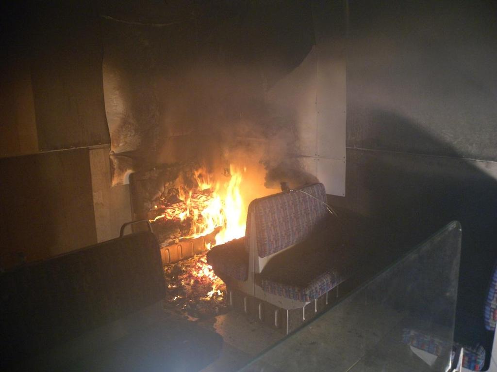
8 8 2 Experimental work A total of six tests were carried out in the 1/3 train carriage mock-up built inside SP s large fire hall. In each test different sets of fire load and ignition sources were used to investigate the fire spread and the occurrence of a flashover. Further, gas temperatures and the heat release rate were investigated. The dimensions of the mock-up were 6 m 3 m 2.4 m (L W H) with two openings, see Figure 1. The open end of the model had a 0.5 m high edge to create a smoke layer in the carriage. The inner linings, walls and ceiling, were covered with non-combustible boards (Promatect H). The floor was covered by 12 mm plywood boards. In the corner where the fire was started, i.e. the corner marked red in Figure 1, the non-combustible boards were covered with combustible 1 mm HPL (high pressure laminate, density of 1400 kg/m 3 ) boards. Figure 1 1/3 train carriage mock up. The width of train carriage was 3 m.

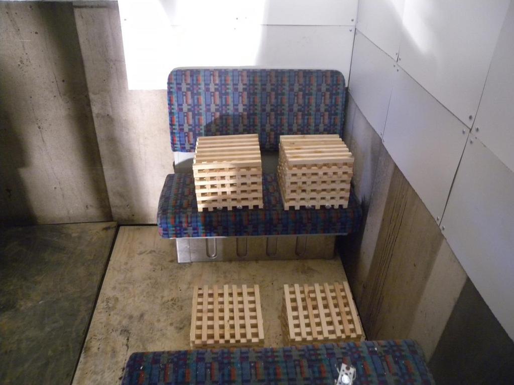
9 9 2.1 Ignitions source In tests 1 to 4 the ignition source consisted of wood cribs, see Figure 2, and in test 5 and 6 the ignition source consisted of 1 liter of petrol, see Figure 3. Figure 2 Geometry of the wood cribs used as ignition source. The wood cribs were made of wood sticks, each 272 mm long and with a cross section of 18 mm. In total there were 12 layers of sticks, with 7 sticks in each layer. To ignite the wood crib, stick 3 and 5 in the bottom layer were made of fiber-board and soaked in heptane. The estimated heat release was 150 kw per wood crib. In Appendix D, photos from each test are shown, and where the location of the ignition source can be observed. When petrol was used as the ignition source, a milk container was filled with 1 liter of petrol. Four small flames were lit, two on the floor and two on the seat, see the four red circles in Figure 3. The petrol was lit by pulling a string attached to the milk container and spilling the petrol over the flames. Figure 3 Picture from test 5 showing the experimental set-up with milk container filled with petrol. Positions of flames are marked with a red circle, the lower two were placed on the floor in front of the backpack. The maximum heat release rate of the petrol was estimated from the initial heat release rate in test 5 and 6, see Figure 4. During the first 15 s the heat release rate increases at approximately the same rate in both test 5 and 6. Since there was very little time for flame spread, this increase in heat release is most certainly due to the burning petrol. In both test 5 and 6 the heat release rate levels off at about 440 kw, see Figure 4, and after that there is a small decrease in HRR before the flames spread rapidly in test 6 and more slowly in
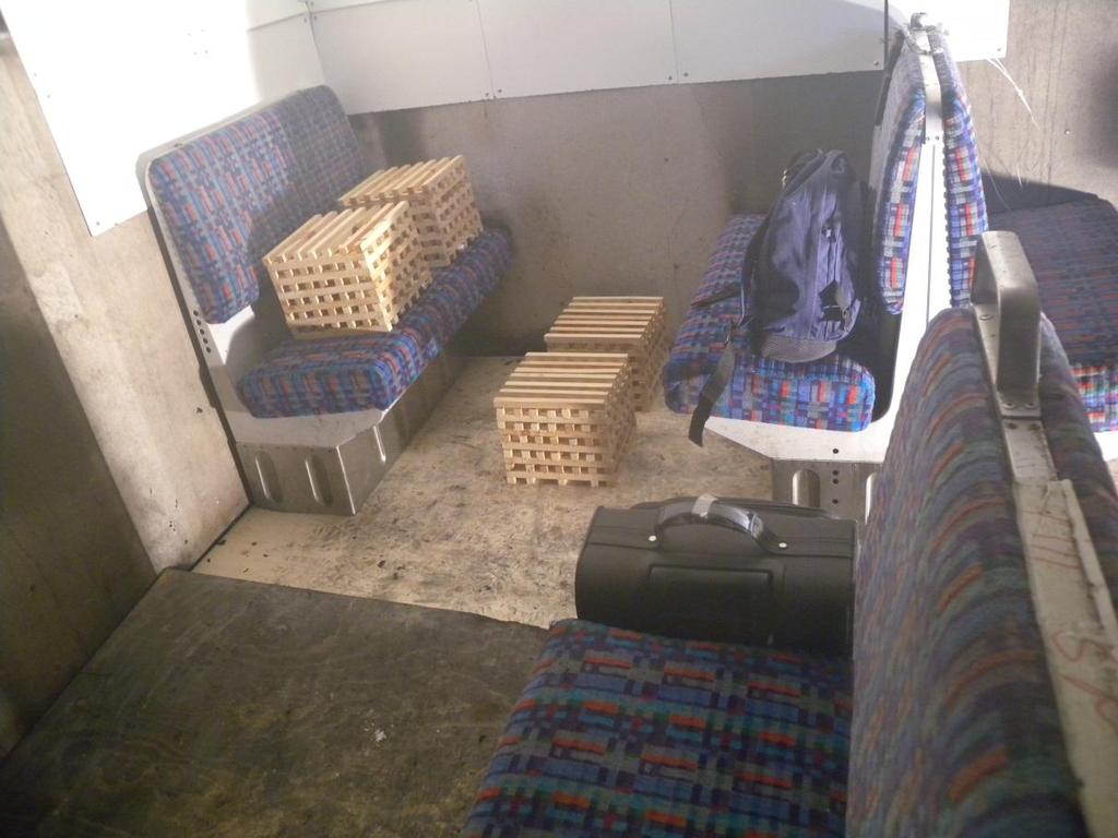
10 10 test 5. See Chapter 4 for more detailed information about the continuous development. The conclusion is that the maximum effect of the petrol used for ignition is 440 kw. Figure 4 The measured heat release rate from test 5 and 6 between 0 and 0.5 min to see max HRR of petrol. 2.2 The fire load The fire load consisted of wood cribs, petrol, seats, linings, bags and a baby carriage. The combustible parts (in addition to luggage and baby carriage) consisted of 10 passenger seats in varying sizes, see Figure 5, floor in plywood and HPL boards on the walls and roof near the seat where the fire was ignited. Wood cribs were, besides from ignition source, used as fire load in test 3 and 4. The cribs were then placed on the floor in front of the seat where ignitions source was placed, see photos in Appendix D. Figure 5 Schematic sketch over seat configuration in the train carriage mockup. Seats are in this report named S1 S10. Passenger seats: Seats were taken from an X1 train and installed in the train carriage mockup. The seats consisted of, from the top: fabric 3 mm, foam (seat 60 mm and backrest mm, respectively), cork wood 9 mm and painted wooden board 4 mm [5]. Cone calorimeter data for the seat material are given in Table 1.

11 11 Figure 6 Photo of seats in the train carriage mockup. Table 1 Summary of cone calorimeter tests for seats [5] Variable Test 1 Test 2 Radiation [kw/m 2 ] Ignition [min:ss] 00:59 00:49 All flaming ceased [min:ss] 1:57 2:18 Test time [min:ss] 20:00 20:00 Peak heat release rate [kw/m 2 ] Average mass loss rate [g/m 2 /s] Effective heat of combustion [MJ/kg] Max average rate of heat emission [kw/m 2 ] Walls and ceiling: The walls and ceiling was constructed of non-combustible boards (12 mm thick Promatect H). The walls and ceiling near and above the ignition source were covered by combustible high pressure laminate (HPL) boards, see Figure 7. Cone calorimeter data for the HPL are given in Table 2 Table 2 A summary of cone calorimeter tests for HPL boards [4] Variable Test 1 Test 2 Radiation [kw/m 2 ] Ignition [min:ss] NI 65 All flaming ceased [min:ss] Test time [min:ss] Peak heat release rate [kw/m 2 ] Average mass loss rate [g/m 2 /s] Effective heat of combustion [MJ/kg] Max average rate of heat emission [kw/m 2 ] Density [kg/m 3 ] NI = No ignition

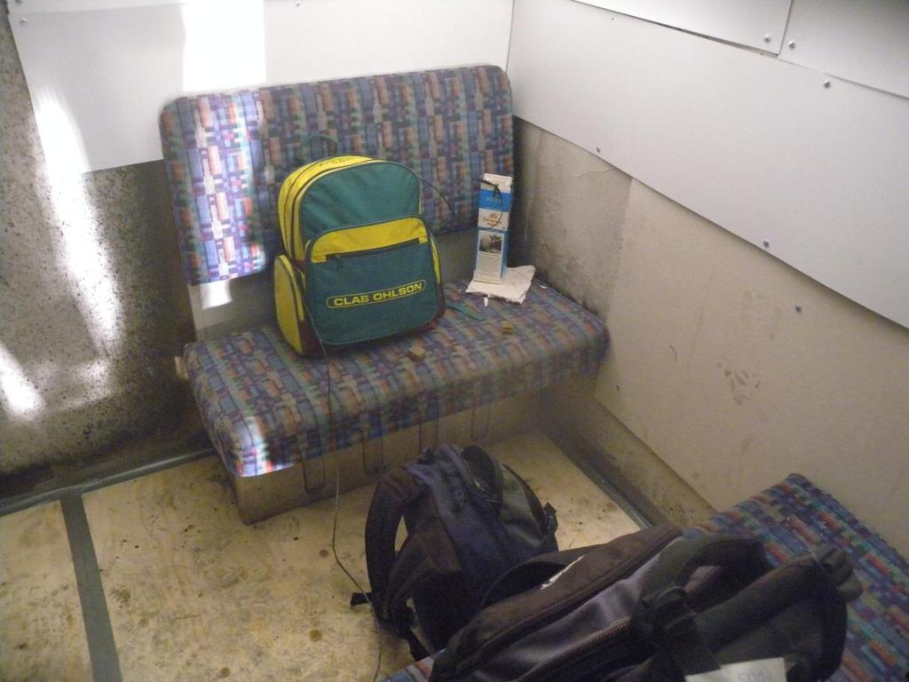
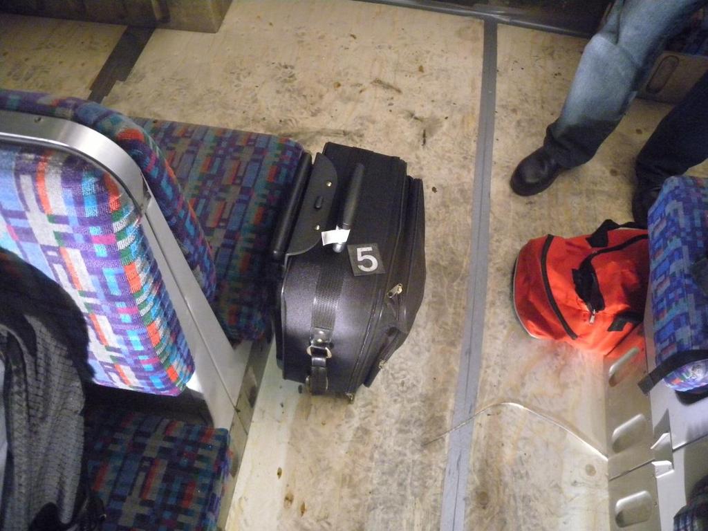
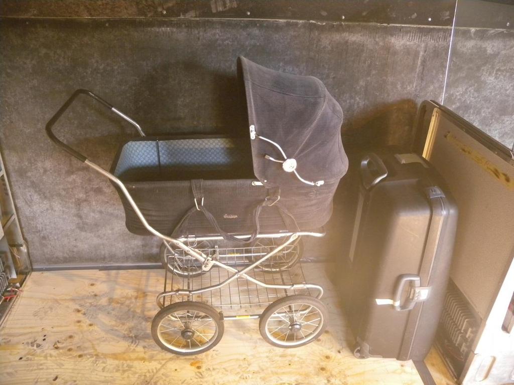
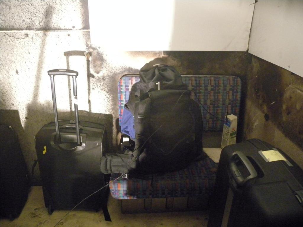
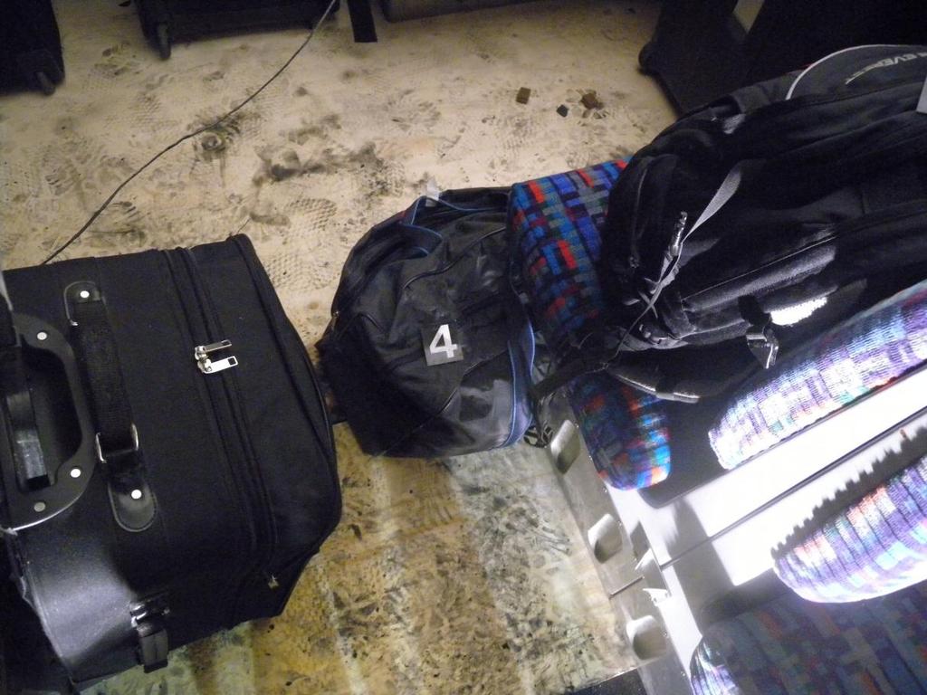
12 12 Figure 7 A photo of the HPL boards on the wall and ceiling above the ignition source. Floor: The floor was covered with 12 mm plywood boards. Table 3. A summary of cone calorimeter tests for plywood boards [4] Variable Test 1 Test 2 Radiation [kw/m 2 ] Ignition [s] Test time [s] Peak heat release rate [kw/m 2 ] Average mass loss rate [g/m 2 /s] Effective heat of combustion [MJ/kg] Density [kg/m 3 ] Thickness[mm] Luggage: Bags with different size and weight were used as fire load in test 4, 5 and 6. The bags were filled with clothes (textile) and paper (cellulosic), see Appendix B. During the tests, the bags were placed in different positions in the train carriage, both on the floor and on seats. In test 5 and 6 a baby carriage was placed close to the opening, see Figure 8. Figure 8 A picture of bags in test 6 (left) and the baby carriage used in both test 5 and 6 (right). See Table 4 in Chapter 3 for a summary of the fire load in the tests and for further details on the fire load in each test, see Appendix B.
13 Instrumentation and measurements The heat release rate was measured using the large scale calorimeter beneath the ceiling of the main fire hall at SP. All the smoke was collected by the hood and then guided to the measurement station in the exhaust duct. The properties of the fire gases were measured in the duct. Then the heat release rate could be calculated using the oxygen consumption technique [6-9]. The gas temperature was measured using welded 0.5 mm type K thermocouples, and in some positions also 0.25 mm type K thermocouples to estimate the effect of radiation on the temperature measurement (this information has not been specifically used in this report). The locations of the thermocouple are shown in Figure 9. Most of the thermocouples were positioned at 0.29 m and 0.05 m below the ceiling, respectively. At measurement point P3, P5, P7, P9, P11 and P14 thermocouples were placed at 0.29 m below the ceiling. At measurement point P4, P6, P8, P10 and P12 thermocouples were placed 0.05 m below the ceiling. Thermocouples were also placed next to plate thermometers in measure point P4, P6, P8 and P10, see Figure 9. One thermocouple tree with thermocouples at heights of 0.05 m, 0.15 m, 0.29 m, 0.60 m, and 1.0 m from the ceiling was placed in position P1 (see Figure 9). This was included to measure the vertical temperature distribution above the ignition position. Heat fluxes towards the seat backrest were measured using plate thermometers [10-12], see P4, P6, P8, and P10 in Figure 9,. The heat flux is important knowledge when one will investigate the time of fire spread between the seats. The incident heat fluxes were calculated using the following equation [10, 11]: j 1 j 4 j j [ TPT ] [ TPT ] PT [ TPT ] ( hpt Kcond )([ TPT ] Tg ) Cheat, 1/ 3 j 1 j j 1 t t inc (1) PT [ q ] where the conduction correction factor Kcond = 8.43 W/m 2 K, the lumped heat capacity coefficient Cheat,β=1/3 = 4202 J/m 2 K, and the surface emissivity of the plate thermometer =0.8. PT P1 P2 P4 P8 P12 P3 P5 P7 P9 P11 P14 P6 P10 P13 Figure 9 Thermocouple and plate thermometer placement in the train carriage.
14 Theoretical aspects of flashover The flashover is the stage in the fire development between the growth phase and the fully developed fire. Significant for this phase is that the fire rapidly changes from involving just a part of the compartment to involving all combustible material within the compartment [13]. A flashover usually demands a gas temperature of C or a radiant heat flux towards the floor of kw/m 2 [13]. The conditions necessary for flashover can also be linked to a critical heat release rate. The heat release rate necessary is in turn dependent on the geometry of the compartment, opening areas and the thermal properties of the walls [14]. The heat release rate necessary ( ) for flashover in this particular case was calculated using equation 2 and 3 [14]. ( ) Areas can be calculated from Figure 1, =71 m 2, =8,23 m 2, = 0.19 W/m/K (Promatect H), = m (Promatect H), = 0.14 w/m/k (Plywood), = m (Plywood). This resulted in = kw/m 2 K, H=1.9 m and therefore = 2100 kw. This information will be used later in the analysis of the measured heat release and observations about the fire development. This vital information is to better understand what energy is required for the test mockup to flip over to a fully developed fire where everything inside the carriage is burning (flashover). It is also important to know where the border line is between go and no go for a flashover situation.
15 15 3 Experimental procedure A total of six tests were carried out, each test with an increasing amount of fire load. The ignition source was placed in the same position in all the tests, see corner marked red in Figure 1. In tests 1-4 the ignition source (wood crib) was placed on the seat and in test 5 and 6 petrol was spilled on the seat and on to the floor making the fire start both on the seat and on the floor at the same time. For each test, the logging system was initiated two minutes prior to ignition. The fire was extinguished either if decay was observed before a flashover occurred or shortly after the flashover occurred; except for test 6 where the fire was extinguished when flames broke through the ceiling. If not specifically stated, all times relate to ignition time. Table 4 Overview of tests 1-6. More details about each test is given in Appendix B. Test no. Fire load Time of flashover 1 Extinguish time (min:ss) 1 Seats and linings 1 wood crib (ignition source) - 23:00 2 Seats and linings 2 wood cribs (ignition source) - 23:00 Seats and linings 3 2 wood cribs (ignition source) 2 wood cribs - 38:00 Seats and linings 4 2 wood cribs (ignition source) 2 wood cribs Bags ( g) 14:00 14:12 Seats and linings 5 1 liter of petrol (ignition source) Bags ( g) Baby carriage - 25:00 Seats and linings 6 1 liter of petrol (ignition source) Bags ( g) Baby carriage 2:13 7:20 1. If flashover didn t occur no time is presented

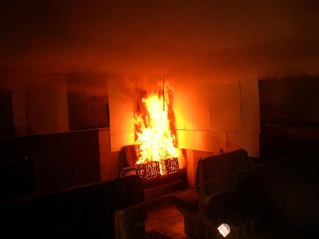
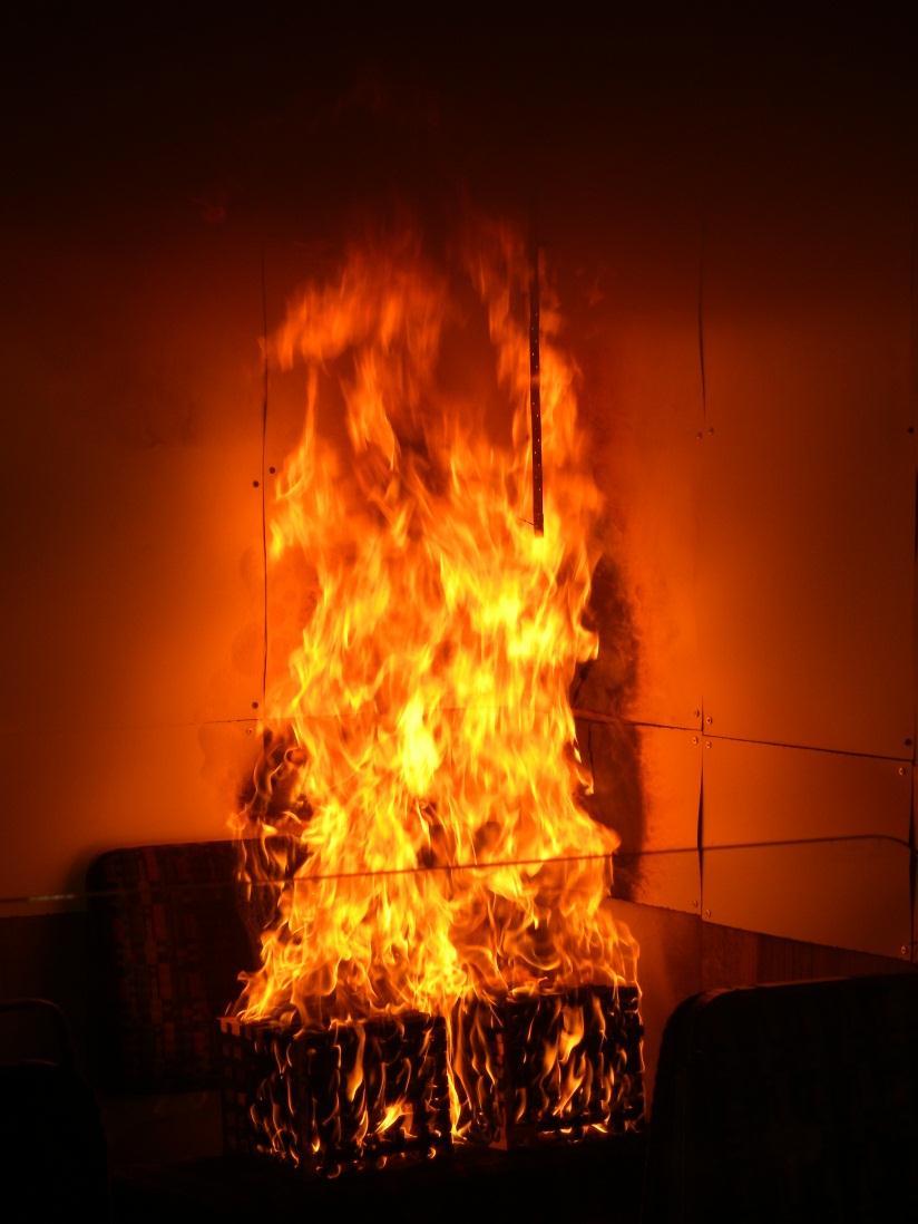
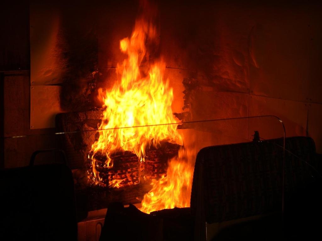
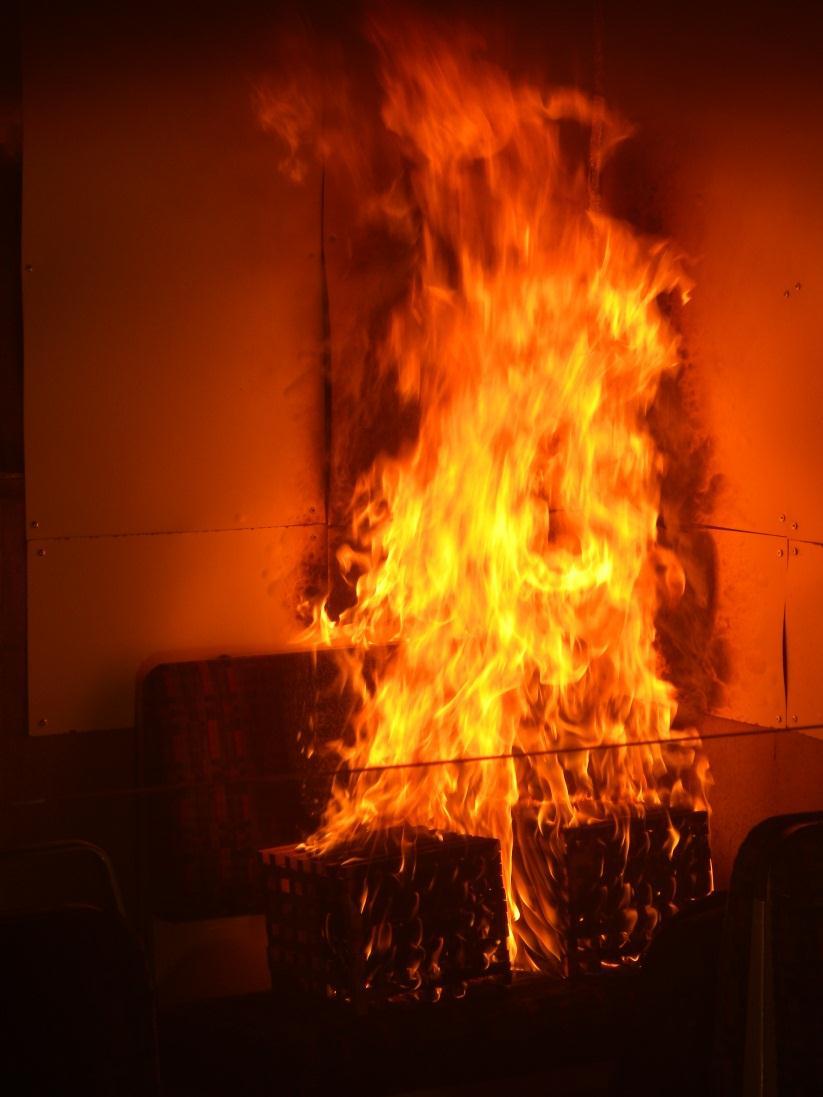
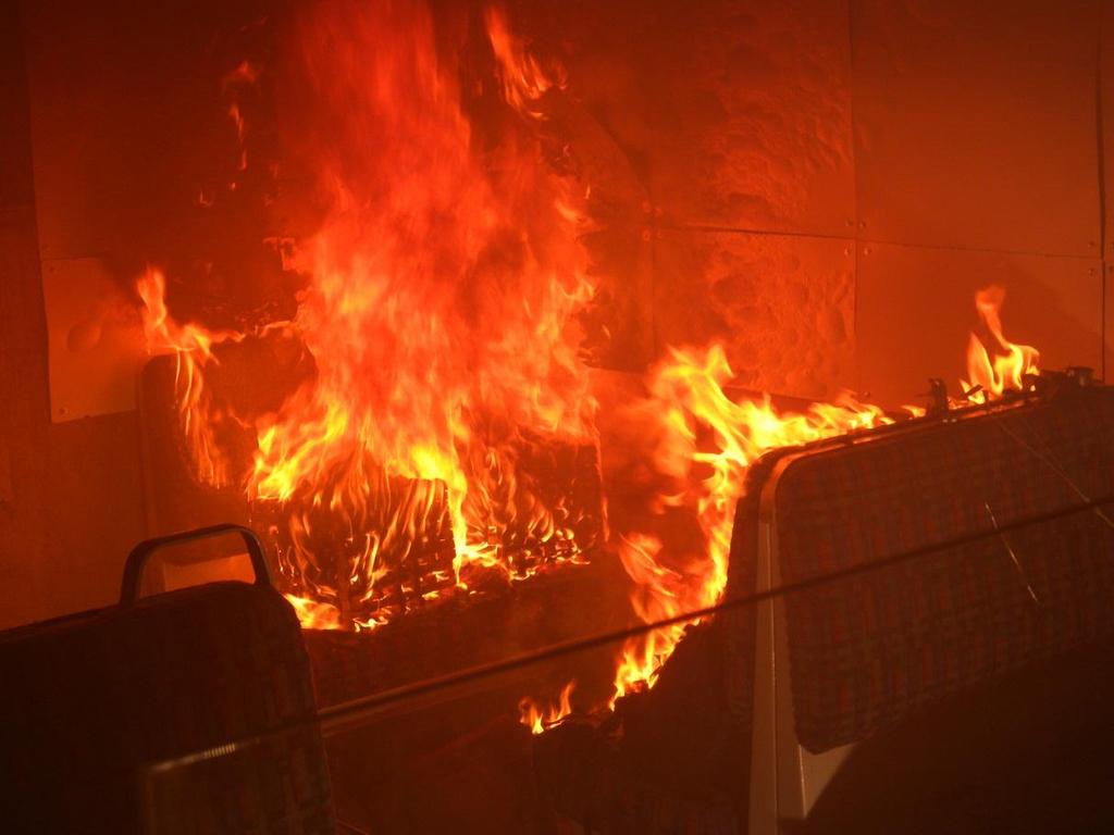
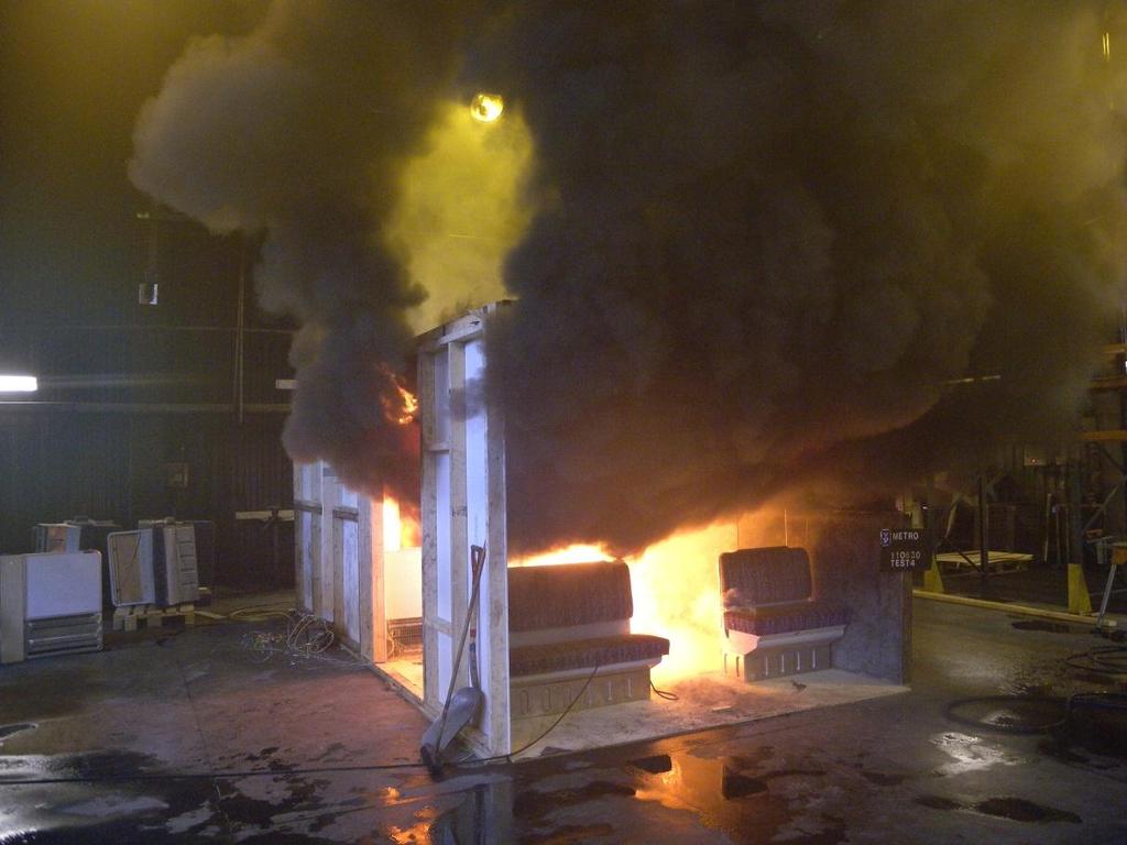
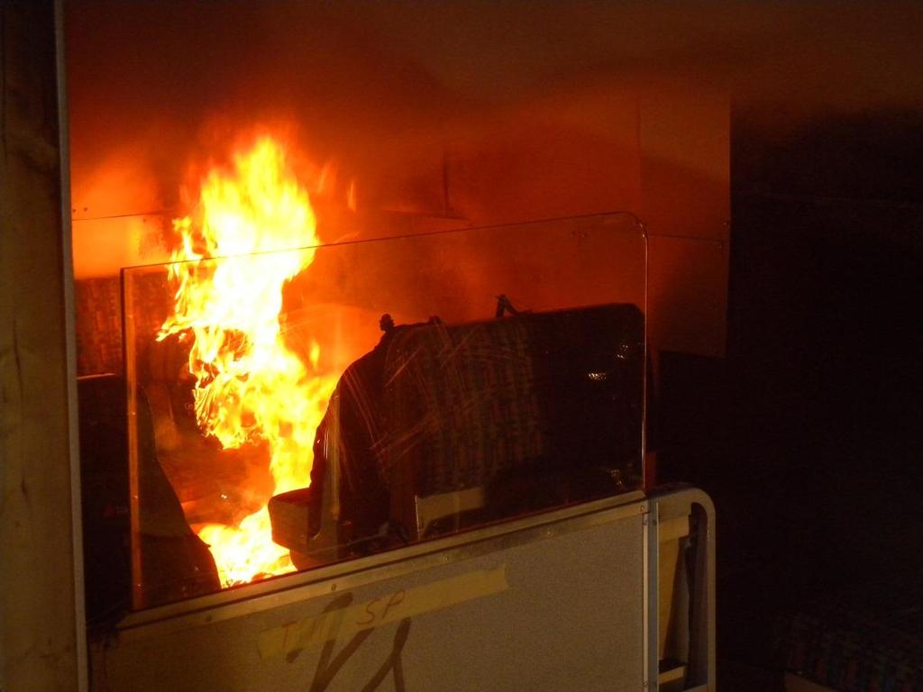
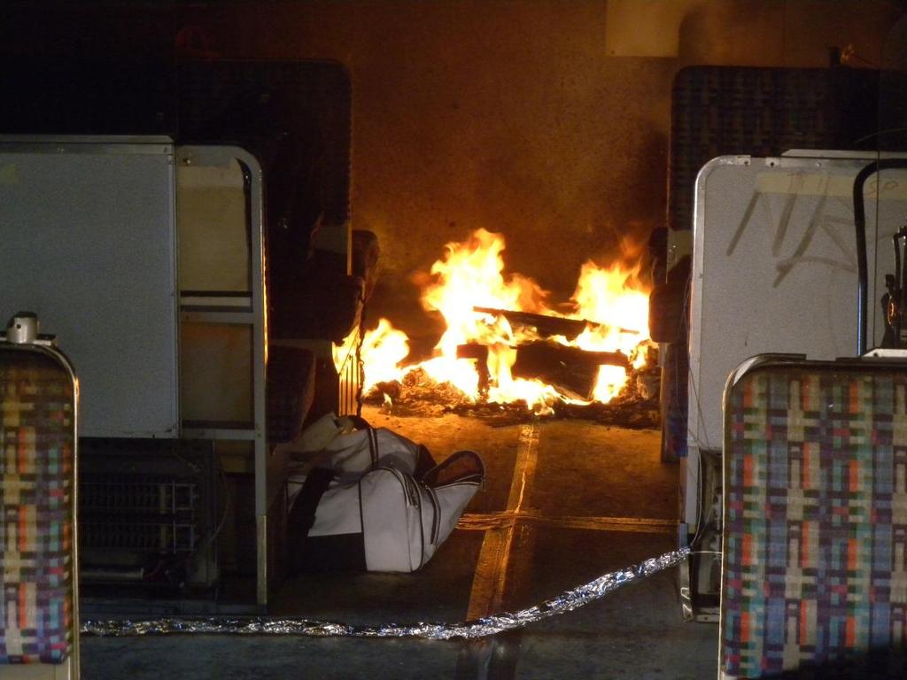
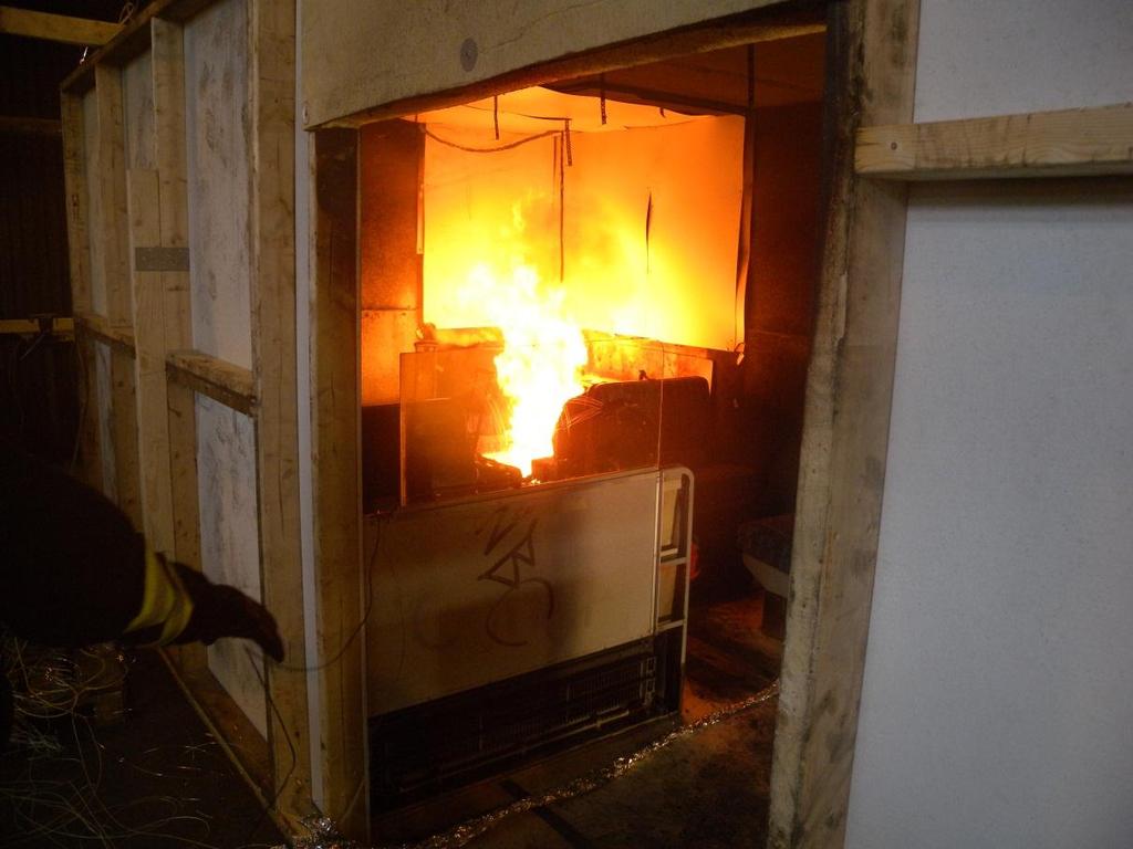
16 16 4 Results In the following, a presentation of the test results is given. Detailed test results for each test are given in Appendix A Test Results. The discussion of the tests results are presented in chapter Summary of measured parameters In the following sections the measured parameters are presented Fully developed fire The test series started with a small ignition source (one wood crib) and no extra fire load besides the seats and the linings. For each test a more powerful ignition source and/or greater fire load was added. In this section the observed time for flashover is compared to the theory presented in section 2.4. In Figure 10 a picture of a fully developed fire in test 6 is presented. The picture is taken shortly after flashover occurred. Figure 10 A photo of the fully developed fire in test 6. In Table 5 the estimated time to flashover are based on three criteria that were measured during the tests : heat release rate, gas temperature and heat flux in the carriage, which were compared to visual observations. The heat release rate criteria, 2.1 MW, was calculated based on the dimensions of the mockup and the properties of the linings using Equation (3), see section 2.4 for more details. The criteria for gas temperature was set to 600 C and the criteria for heat flux has been set to 20 kw/m 2 [13]. The listed values in Table 4 in the HRR column represent the time to a heat release rate of 2.1 MW. The listed values in the Gas temperature column represent the time of 600 C in thermocouple P14, see Figure 9. Since P14 is placed closest to the opening, the temperature in the rest of the carriage exceeds 600 C. The listed values in the Heat flux
17 17 column represent the time when the incident heat flux towards plate thermometer P10, see Figure 9, reached 20 kw/m 2. The listed values in the Observations column in Table 5 are based on visual observations from videos, photos and measurements from the test. Table 5 Occurrence of flashover and estimated time to flashover. Estimated time to flashover [min:ss] Test Flashover Gas no. occurred HRR Heat flux Observations temperature 1 No No No Yes 13:42 13:56 13:38 14:00 5 No Yes 2:00 2:12 2:02 2:13 The results indicate that the criteria for a flashover for this test setup are very well predicted. All three criteria are met at about the same time in both tests. The calculated conditions are slightly less in time than the observations, not more than 3 % difference in test 4 and 10 % in test 6. This means that the equation (3) works well for the test conditions and it shows that when the heat release rate reached 2.1 MW, a flashover inside the wagon is established. Everything inside the room is burning or is about to ignite. The maximum heat release rate obtained in these tests was 3.5 MW. The duration of the flashover was too short to know if a steady state flashover conditions were established Heat release rate Figure 11 and Figure 12 present the heat release rate for each test and in Table 6 a summary of maximum heat release rate for each test is presented. Table 6 Maximum HRR and estimated time of maximum HRR. Test no. Maximum HRR [kw] Estimated time to maximum HRR [min:ss] : : : : : :00 When a flashover is established we know that 2.1 MW is required. If analyzing the figures 11 12, we observe that if the heat release rate becomes higher than kw, a fire development that grows to a flashover is obtained. This is the minimum heat release rate required in order to continue the fire growth. This number shall not be compared directly with 2.1 MW, which is the calculated value when a flashover is established.
18 18 Figure 11 Heat release rate in test 1 3 Figure 12 Heat release rate in test 4 6. The fire was manually extinguished after 14 min in test 4 and in test 6 it was manually extinguished after approx. 7 min.
19 Gas temperatures Test results related to the measured gas temperatures are in detail presented in Appendix A. In Table 7 center line temperatures at 28.8 cm below the ceiling are presented, where thermocouple P3 is furthest into the carriage and P14 is closest to the opening. The listed values represent the temperature, measured in each thermocouple, at the time (t p14,max ) of maximum temperature in thermocouple P14 during the test. The locations of the thermocouples are shown in Figure 9. Table 7 Temperatures in the centrum line of the train carriage mockup at the time of maximum temperature in thermocouple P14. Test No. t p14,max T P3 T P5 T P7 T P9 T P11 T P14 [min:ss] [ C] [ C] [ C] [ C] [ C] [ C] 1 6: : : : : : In Figure 13 to Figure 15 center line gas temperatures from each test is presented. I the figures below measure point P5, P9 and P11 are excluded to make the diagrams easier to interpret. Figure 13 Center line temperatures in test 1 and 2.
20 20 Figure 14 Center line temperatures in test 3 and 4. Figure 15 Center line temperatures in test 5 and 6. In test 6 several of the thermocouples reported void data between 5 and 10 min, this could be because the fire broke through the ceiling after about 7 min and destroyed the thermocouple suspension and/or the thermocouples themselves. Another possibility is that the void data is a result of the fire extinguishment that started after about 7-8 min. In any case it does not affect the conclusions or the findings presented here. In Table 7 and Figure 13 to Figure 15 we observe that the gas temperatures are of the order of C when no flashover was obtained and over 900 C when flashover was reached. The reason is rather evident; in the case of a flashover the flame volume reached the front of the carriage and in the case of no flashover they did not reach further than to the base of seat S2 and S4. In all tests that did not reach flashover the temperatures were less than about 450 C in P3, which indicates that the flames did not reach to that area. This also indicates that in order to obtain a flashover you need the flames to reach to the ceiling and bend towards the opening. Usually the flame tip is defined as an excess temperature of 500 C and for flashover we need to get up to 600 C. This indicates that the boundary between go or no go for flashover is quite narrow.
21 Heat flux Heat flux was measured using plate thermometers placed on the backrest of four seats in positions P4, P6, P8 and P10 (in vertical position, centrally at the top of the backrest and directed towards the back wall and ignition position), see Figure 9. Heat fluxes are calculated according to equation (1). Table 8 presents the time until the incident heat flux exceeded 15 and 25 kw/m 2. In Figure 23 to Figure 28 heat fluxes during each test are presented. Table 8 Time until incident heat flux towards plate thermometers on the backrest of four seats exceeded 15 and 25 kw/m 2. Times are given in min:ss. P4 (Seat S3) P6 (Seat S4) P8 (Seat S7) P10 (Seat S8) Test No kw/m 2 kw/m 2 kw/m 2 kw/m 2 kw/m 2 kw/m 2 kw/m 2 kw/m : :22 11: :48 10:50 13:12 13:22 13:36 13:43 13:35 13:40 5 2:16 2: :40 1:14 2:00 2:04 2:17 2:19 1:42 2:04 Figure 16 Heat Flux towards seat S3 (measurement point P4). Test 1-3 to the left and test 4-6 to the right.
22 22 Figure 17 Heat Flux towards seat S4 (measurement point P6). Test 1-3 and 5 to the left and test 4 and 6 to the right. Figure 18 Heat Flux towards seat S7 (measurement point P8). Test 1-3 and 5 to the left and test 4 and 6 to the right.
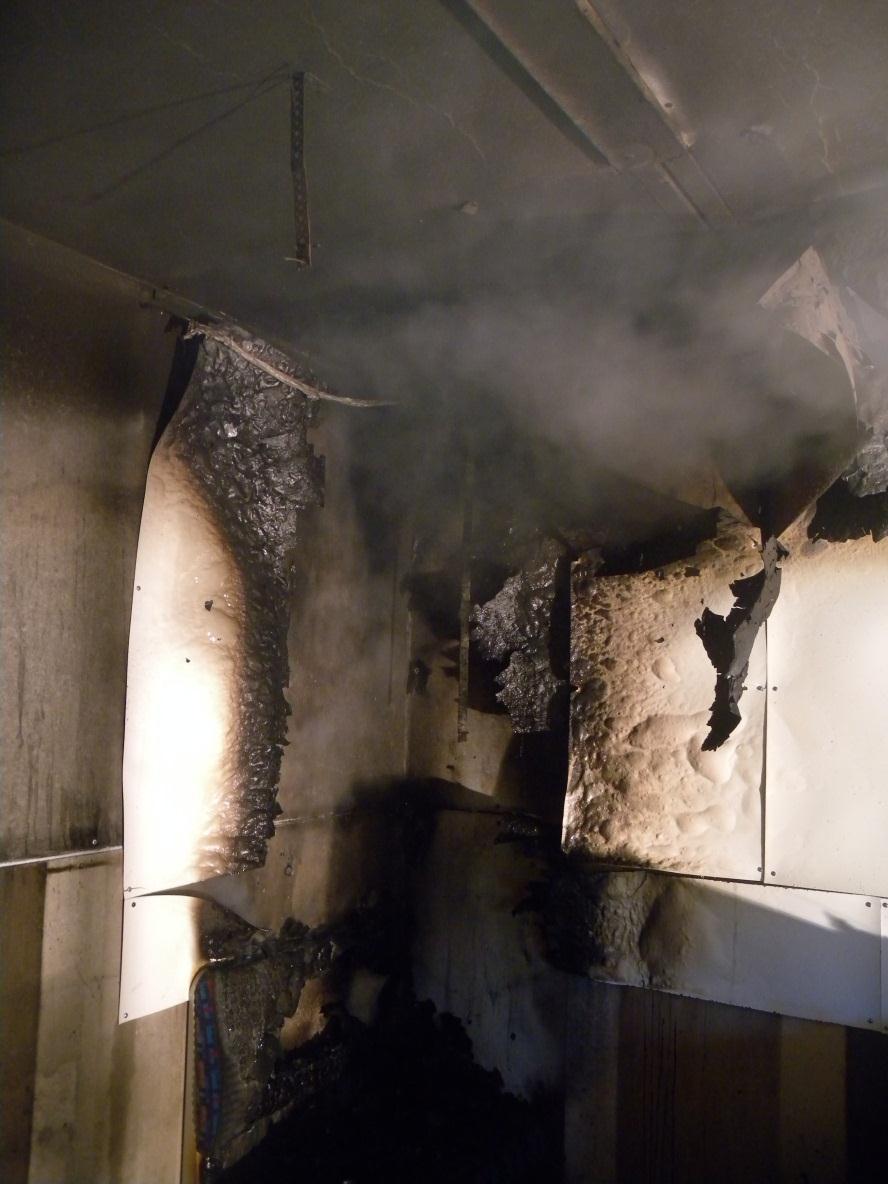
23 23 Figure 19 Heat Flux towards seat S8 (measurement point P10). Test 1-3 and 5 to the left and test 4 and 6 to the right. The information in figures 17 to 19 can be used to interpret the risk for fire spread between the seats. In tests 3, 4, 5 and 6, the incident radiation at seat S3 (measurement point P4), all exceed the value of 20 kw/m 2, at some stage of the fire development. Comparing this information with which tests the fire spread to the opposite seat of the ignition seat, a good correlation was found, see test protocols in Appendix B. This is also confirmed by the values given in Table 7. In conclusion, in order to obtain a flashover, the fire has to spread further than the seat S3. A more accurate analysis of the fire spread is given in the following subsections. 4.2 Flame spread Flame spread is dependent on a number of variables, e.g. geometry, the heat release of the ignition source, linings and seats, air flow, the amount of fire load and how the fire load is distributed in the compartment. Flame spread is also dependent on heat flux from existing flames and hot gas layers, but these are in turn dependent on the mentioned variables. In the executed tests only the ignition source, amount of fire load and the distribution of the fire load varied. The observed flame spread and how it varied with different variables is presented and discussed below Vertical flame spread All tests were carried out with combustible HPL boards on the walls and ceiling above the ignition source, see figure 7. The rest of the walls and ceiling was constructed in noncombustible boards. The vertical flame-spread on the HPL boards was relatively similar in the different tests with wood cribs as the ignition source. In these tests the flames spread in the corner up to the ceiling. In the case of a liquid ignition source (petrol), the vertical flame spread differed between test 5 and 6. In test 5 it was very weak, see pictures from test 5 in Appendix D Photos from tests, and in test 6 it was extremely strong. A possible explanation is that this is related to the disposition of the bags that was placed in the vicinity of the ignition source, see Figure 20.

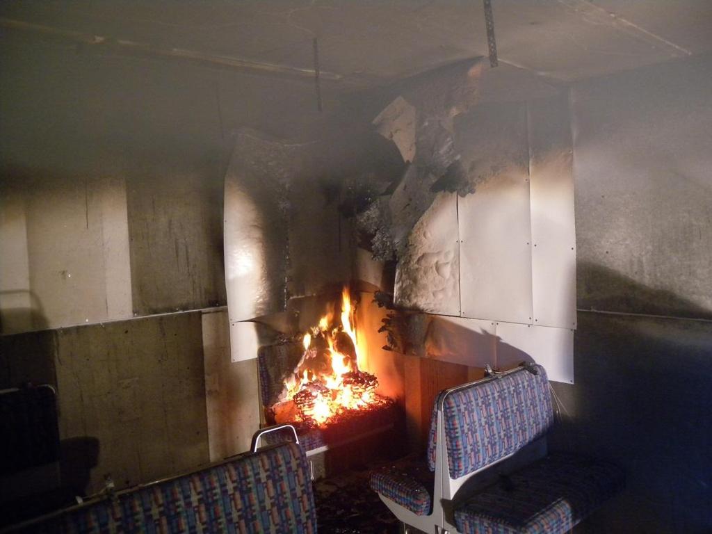
24 24 Figure 20 Disposition of bags in the vicinity to the ignition source in test 5 (left) and test 6 (right). In test 5 bags were placed away from the wall making it more difficult for the flames to spread to the HPL boards and in test 6 the bags were larger and placed closer to the wall. The weak vertical flame spread in test 5 probably influenced the horizontal flame spread and could have been one of the reasons why the fire never reached flashover. In the tests with a strong vertical flame spread the radiation towards the fuels (luggage and seats) ahead of the flame-front was higher. This higher level of radiation probably served to preheat fuel which fostered horizontal flame spread. This could be the reason why flashover was observed in test 4 and not test 5 even though the fire load was significantly higher in test 5. The difference in radiation can be seen in Figure 21 below, where the heat flux towards seat S4 is plotted. Figure 21 Heat flux towards seat S4 in test 4-6. Note that the heat flux axis has been limited to 25 kw/m 2 to be able to see the difference between the tests. The time of increased radiation in test 4 correspond to the time when the flames started to spread to the HPL boards. The vertical flame spread might also have accelerated the horizontal flame spread by making burning HPL boards fall from walls and ceiling and on to seats and floor. The falling HPL boards were observed in test 4 and 6. An example of this can be seen in Figure 22 and Figure 23. The figures show snapshots from test 6 shortly before and after a big piece of the ceiling HPL board fell. In Figure 23 it is possible to see burning pieces of HPL boards on seat S4.

25 25 Figure 22 Test 6 shortly before a big piece of the burning HPL boards fell (time 1:21) Figure 23 Test 6 shortly after a big part of the burning HPL boards fell (time 1:25). The HPL board fell at 1:23. The fallen HPL board can be seen in the middle of the carriage between seat S3 and S4. Even though the falling HPL boards were only observed in the tests which resulted in flashover it is not likely that this initiated the flashover. Since the HPL boards fell approx. 40 s before flashover in test 6 and approx. 8 min before flashover in test 4 this indicates that this is just a part of the fire growth.
26 Horizontal flame spread The general conclusions are that the horizontal flame spread followed three steps in the train carriage, see Figure 24: Step 1: After ignition flames spread from seat S1 towards S3. Step 2: When seat S3 ignited, or shortly before, the flames started to spread towards seat S2 and S4. Step 3: After seat S4 ignited the flames started to spread over the full width of the train carriage towards the opening. This is, of course, a very simplified model of the fire spread, but these were the trends. The tests that did not lead to a flashover followed the same pattern but the decay started during step 1 or 2 depending on the varied variables. For more details about flame spread in the different tests see Appendix C Flame spread. Figure 24 Schematic picture of flame spread in the train carriage in three steps Horizontal flame spread compared with ignition source In Table 9 and Table 10 the maximum heat release rate of the ignition source is compared with the stage in which the fire spread stopped. In Table 9, the tests where wood cribs were used as ignition source are compared. The tests where petrol was used as ignition source are presented in Table 10. Table 9 Maximum heat release rate of ignition source (wood cribs) compared to the step (1-3) in which the fire spread stopped. Test No. FO Ignition source [kw] Fire was extinct or decay started during 1 No 150 Step 1 (fire never spread to seat S3) 2 No 300 Step 1 (fire never spread to seat S3) 3 No 300 Step 1 (fire spread to seat S3, but not to S4) 4 Yes 300 Step 3 (fire was extinct after flashover) FO = flashover Table 10 Maximum heat release rate of ignition source (petrol) compared to the step (1-3) in which the fire spread stopped. Test No. FO Ignition source [kw] Fire was extinct or decay started during 5 No 440 Step 2 (Seat S4 never ignited) 6 Yes 440 Step 3 (Fire reached a fully develop stage) FO = flash over There was a significant difference in horizontal flame spread in the early stage of the fire depending on whether the ignition source was solid or liquid. When liquid (petrol) was

27 27 used there was a fast horizontal flame spread towards seat S3, since the petrol was spilled also on the floor. In the tests where flames actually spread to seat S3, the difference in flame spread time between solid and liquid ignition source was about 3-5 min Horizontal flame spread compared with amount and disposition of fire load To be able to compare the amount and disposition of the fire load (in addition to the ignition source) with flame spread, the steps (1-3) are divided into 3 zones, see Figure 25. The comparison is presented in Table 11, Table 12 and Table 13. Figure 25 Train carriage divided into three zones to compare fire load (amount and disposition) with flame spread. Table 11 Fire load in zone 1 in addition to ignition source, see zones in Figure 25. Zone 1 Test FO Fire load (g) Luggage Wood crib Fire was extinct or decay started during 1 No - - Step 1 (fire never spread to seat S3) 2 No - - Step 1 (fire never spread to seat S3) 3 No Step 1 (fire spread to seat S3, but not to S4) 4 Yes Step 3 (fire was extinct after flashover) 5 No Step 2 (Seat S4 never ignited) 6 Yes Step 3 (Fire reached a fully develop stage) FO = flashover Table 12 Fire load in zone 2, see zones in Figure 30. Zone 2 Test FO Fire load (g) Luggage Wood crib Fire was extinct or decay started during 1 No - - Step 1 (fire never spread to seat S3) 2 No - - Step 1 (fire never spread to seat S3) 3 No - - Step 1 (fire spread to seat S3, but not to S4) 4 Yes Step 3 (fire was extinct after flashover) 5 No Step 2 (Seat S4 never ignited) 6 Yes Step 3 (Fire reached a fully develop stage) FO = flashover
28 28 Table 13 Fire load in zone 3, see zones in Figure 30. Zone 3 Test FO Fire load (g) Luggage Wood crib Fire was extinct or decay started during 1 No - - Step 1 (fire never spread to seat S3) 2 No - - Step 1 (fire never spread to seat S3) 3 No - - Step 1 (fire spread to seat S3, but not to S4) 4 Yes - - Step 3 (fire was extinct after flashover) 5 No Step 2 (Seat S4 never ignited) 6 Yes Step 3 (Fire reached a fully develop stage) FO = flashover In Figure 26 the disposition of the fire load is presented. Only the tests where fire load besides the ignition source were used are included. Pieces of luggage are numbered and wood cribs are marked with W. Figure 26 Disposition of fire load in test 3 (top left), 4 (top right), 5 (bottom left) and test 6 (bottom right). Comparison between the tests: Test 1 and 2: No extra fire load, such as luggage or wood cribs, was added in test 2 and no difference in flame spread between the two tests was observed. Test 2 and 3: Extra wood cribs were placed on the floor in test 3 and the flames spread to seat S3. It appears as if the extra fire load on the floor made the fire spread but was insufficient to cause flashover. Test 3 and 4: Additional luggage was placed in zone 1 and 2 and in between seat S3 and S4 in test 4 and a flashover was observed in test 4. It appears as the extra bags made the flames spread to zone 2 leading to higher heat release rates and consequently a flip over to a flashover in zone 3. Test 4 and 5: In test 5 the amount of luggage was doubled in zone 1, kept almost the same in zone 2 and luggage was also placed in zone 3, still the fire never spread to zone 2. Petrol was used as ignition source. It appears as the replacement of the wood cribs on the floor with extra bags made the flame spread stop before seat 2 and 4 was ignited. The distribution of fuel was also different in Test 5 from Test 4. A flashover was observed in test 4. Test 5 and 6: In test 6 a larger bag was placed between seat 1 and 3 and bags were also placed between seat 1 and 2. It appears as if this made the fire spread
29 29 very rapidly into zone 2 resulting in a flashover in zone 3. In conclusion, in order to obtain a flashover, the fire had to spread to zone 2 and consequently to zone Horizontal flame spread compared to incident radiant heat flux towards the seats Incident radiant heat flux from the flames and the hot gas layer will cause an increase in the rate of flame spread. This is mainly because of preheating of the fuel, in this case seats, luggage and floor. At high levels of radiant heat fluxes the exposed fuel can selfignite but at lower levels the fuel can be ignited with a pilot flame. How the fuel reacts to radiant heat flux is very dependent on the thermal properties of the fuel. Most fuels will either self-ignite or ignite with a pilot flame at kw/m 2. In the executed tests, the incident heat flux was measured on the backrest of seat S3, S4, S7 and S8. In Table 14 and Table 15 time until the incident heat flux towards the seats are 15 kw/m 2 and 25 kw/ m2, respectively, is compared with the time until flames were observed on the seats. Table 14 Times for when the measured incident heat flux reached 15 kw/m 2 and 25 kw/m 2, respectively, are compared with the observed fire spread to seat S3 and S4 [min:ss]. P4 (Seat S3) Estimated time P6 (Seat S4) Estimated time Test No to ignition of to ignition of seat kw/m 2 kw/m 2 seat S3 kw/m 2 kw/m 2 S : :12 11:44 6: :45 10:50 5:00-6:00 13:12 13:22 14:00 5 2:14 2:18 2:00 3: :36 1:12 1:30 2:00 2:04 2:13 Table 15 Times for when the measured incident heat flux reached 15 kw/m 2 and 25 kw/m 2, respectively, are compared with the observed fire spread to seat S7 and S8 [min:ss]. P8 (Seat S7) Estimated time P10 (Seat S8) Estimated time Test No to ignition of to ignition of kw/m 2 kw/m 2 seat S7 kw/m 2 kw/m 2 seat S :36 13:43 14:05 13:35 13:40 14: :17 2:19 2:18 1:42 2:04 2:18 As can be seen in Table 14 and Table 15, the correlation between the incident heat flux and the time of fire spread to each seat is consistent for most of the cases. There is a tendency that the observed fire spread correlates better with the time corresponding to 25 kw/m 2 for seats S4, S7 and S8, whereas for seat S3 it is not as consistent.
30 30 5 Discussion of results A total of six tests were carried out in the 1/3 train carriage mock-up. The aim was to investigate how the ignition source (solid and liquid) and amount and disposition of fire load affected the fire development, fire spread, and maximum size of the fire. Of particular interest was which ignition procedure and luggage setup that resulted in a flashover in the train carriage. The test series started with a small ignition source (one wood crib) and no extra fire load apart from the seats and the lining. For each test a more powerful ignition source and/or greater fire load was added to the train carriage. Only two of the tests resulted in a flashover, i.e. test 4 and 6, respectively. In test 4, a flashover occurred approximately 14 min after ignition and in test 6 after approximately 2 min. The most significant difference between these tests was that wood cribs were used as ignition source in test 4 and petrol in test 6 and that test 6 contained approximately ten times the fire load (approx. 220 kg) as in test 4 (approx. 22 kg). Another major difference was that in test 6 bags were placed between seat 1 and seat 2, see Figure 26. This might have been one of the reasons why such a large difference in time to flashover was observed, apart from the total amount of luggage. Another aspect of the disposition of the fire load was observed in test 4 and imitated in test 5. In test 4 a bag between seat 3 and 4 fell into the fire in front of seat 3 after about 9 minutes. This corresponds to the time when the fire in test 4 started to increase which finally lead to a flashover after 14 minutes from ignition. One preliminary conclusion was therefore that this bag was a determining factor in the fire spread. In test 5, fire loads (bags) in the vicinity of the ignition source were placed further away from the walls and closer to seat 2 and 4 (the ignition source was petrol). A bag was also placed between seat 3 and seat 4 in the same way as in test 4. After about 9 min the bag was manually tilted into the fire in front of seat 3 to imitate test 4, but that did not result in any additional flame spread to seat 4. This is particularly interesting since the amount of fire load in zone 1 was doubled in test 5 compared to test 4. One possibility is that this can be traced back to the radiant heat flux from flames on walls and ceiling. In test 4 there was a significantly stronger vertical flame spread than in test 5. The vertical flame spread in test 4 resulted in a significantly higher incident radiant heat flux towards fuel (bags and seats) in zone 2 than in test 5. Since this heat flux started several minutes before fuel in zone 2 ignited, this could have served to pre-heat the fuel and thereby making it possible for flames to spread when the bag fell in test 4 and not in test 5. It is possible that the fire would not have spread if the bag had not fallen in test 4 but by comparing test 4 and 5 vertical flame spread could be said to have played a significant role for the flame spread between zone 1 and 2. The impact of the vertical flame spread could be of interest if new tests were to be conducted without a combustible lining. Since all tests were carried out with HPL boards above the ignition source it is difficult to say what would have happened if they were removed or mounted in the other direction, or if more HPL boards were added. It is, however, very likely that the disposition of the fire load (luggage) would have been more important since there probably would be less pre-heating of fuel ahead of flame front. One should also note that the combustible lining was not easy to ignite. Still it had a significant effect on the fire spread. The importance of the lining on the walls and in the ceiling has also been observed in both model-scale [15] and full-scale tests[3, 4]. In test 4 there was a long growth time before the flashover (during which fuel ahead of the flame front could be pre heated) relative to test 6. This was probably because the luggage in test 6 had been placed in such a manner that the flames could spread both to seat 3 and seat 2 at the same time and because a significantly larger bag was placed between seat 1 and 3. Because of the short time until flashover it is possible that the fire would have grown to a flashover even without combustible linings above the ignition source. This is, however, not certain and there could have been a different time to flashover.
31 31 There was a significant difference in time to flashover and amount of fire load in test 4 and 6, but yet both tests resulted in a flashover. In test 4 there was no luggage in zone 3 and in test 6 the total weight of the bags was 117 kg. This indicates that flashover was not particularly dependent on the amount of fire load in zone 3, but rather on the fire growth in zone 1 and 2. The exposed fuel surface area is although high and that may contribute to the flashover in zone 3. If the fire load in zone 1 is compared between test 4 (approx. 11 kg) and 5 (approx. 22 kg) this suggest that flashover is not dependent on the amount of fire load. If, however, test 5 (approx. 22 kg) and 6 (approx. 66 kg) are compared this suggest that is does. Apart from the impact of vertical flame spread, which has already been discussed, this could imply that when petrol is used as the ignition source the amount of fire load in zone 1 is of importance. In support of this is the combustion pattern of a small petrol pool. An ignited pool of petrol will during a short period release a high amount of heat. For the fire to spread, fuel in the vicinity of the pool must ignite from this heat, but since the heat from the petrol will start to decay quickly the ignited fuel must be able to maintain a sufficient heat release for the fire to keep spreading. If more fuel (luggage) is placed in the vicinity of the pool and in different directions from the pool this should make it more likely for the fuel to maintain a sufficient heat release for the fire to spread, as seen in test 6. This could imply that when a liquid ignition source is used the disposition of luggage in the vicinity of the ignition source is important.
32 32 6 Conclusions A total of six tests were carried out in the 1/3 train carriage mock-up. The aim was to investigate how the ignition source and amount and disposition of fire load affected the fire development. The amount of fire load (luggage and wood cribs) was increased during the test series. The heat release rate from the ignition source was also increased and in the last two tests the ignition source was changed from solid to liquid. Even though not all tests reached a fully developed stage, the fire spread approximately followed the same pattern in all tests. First the fire spread from the ignition source towards the opposite seat (within zone 1), then across the midsection of the carriage (from zone 1 to 2), still limited to the rear section of the carriage. Finally, the fire spread towards the opening, forward in the carriage, across the full width of the carriage (from zone 1 and 2 to zone 3), see Figure 24 and Figure 25. When and where the fire stopped or whether it reached a fully developed stage was mostly dependent on the amount of fire load and how strong the vertical flame spread on the HPL boards mounted to walls and ceiling above the ignition source was. In test 1-3 the fire never reached a fully developed stage and the decay started before the fire reached zone 2. In test 4 on the other hand a flashover was observed. The difference between these tests was the additional luggage placed in zone 1 and 2 in test 4. The conclusion is that the seats alone did not contain sufficient fuel for the fire to spread within the train, and instead there neededto be luggage in between the seats. The results from test 5 suggest that not only the luggage is a key parameter for fire spread. Compared to test 4 the amount of luggage in zone 1 was doubled in test 5, but the fire never developed to a flashover. When the test results were compared, there was a significantly stronger vertical flame spread in test 4 on the HPL boards mounted to the walls and ceiling above the ignition source. The vertical flames resulted in a higher radiant heat flux towards zone 2 and the fuel in this zone was pre-heated to a higher extent than in test 5. This is probably the reason why the fire managed to develop into a flashover in test 4 but not in test 5. The conclusion is that combustible linings can strongly influence the fire development, even if these only are a small proportion of the entire fire load in the train carriage. Because the linings were very sparsely burnt in test 5 and the fire never developed into a flashover, some conclusions regarding a train carriage without combustible linings can be made. In test 5, it seems to be that either there was not sufficient luggage or the disposition was not advantageous enough for the fire to spread. Therefore, the fire development is probably much more sensitive to the amount and disposition of the luggage in a train with non-combustible linings. How much more luggage and in what way it needs to be distributed cannot be determined from these tests because in the other tests the full lining burned. Another aspect regarding the amount of fire load in the train carriage was seen when test 4 and test 6 were compared. In test 4 there was no luggage, but combustible seats with large exposed fuel surface area, in zone 3 while in test 6 the total weight of the luggage was 117 kg, yet both tests resulted in a flashover. The conclusion is that whether the fire reaches a flashover or not is more dependent on the fire growth in zones 1 and 2 rather than on the fuel load present in zone 3.
33 33 7 References 1. Ingason, H., and Lönnermark, A., "The large scale test programme in the METRO project", Eurotransport, 6, pp 62-64, Kumm, M., "Carried Fire Load in Mass Transport Systems - a study of occurrence, allocation and fire behavior of bags and luggage in metro and commuter trains in Stockholm", Mälardalen University, SiST 2010:04, Västerås, Sweden, Lönnermark, A., Lindström, J., Li, Y. Z., Ingason, H., and Kumm, M., "Largescale Commuter Train Tests - Results from the METRO Project", Proceedings from the Fifth International Symposium on Tunnel Safety and Security (ISTSS 2012), pp , New York, USA, March, Lönnermark, A., Lindström, J., Li, Y. Z., Claesson, A., and Ingason, H., "Fullscale fire tests with a commuter train in a tunnel", SP Technical Research Institute of Sweden, SP Report 2012:05, Borås, Sweden, Borgerud, K., "CEN/TS :2009 Railway applications - Fire protection on railway vehicles - Part 2: Requirements for fire behavior of materials and components", Huggett, C., "Estimation of Rate of Heat Release by Means of Oxygen Consumption Measurements", Fire and Materials, 4, 2, 61-65, Parker, W. J., "Calculations of the Heat Release Rate by Oxygen Consumption for Various Applications", Journal of Fire Sciences, 2, September/October, , Dahlberg, M., "The SP Industry Calorimeter: For rate of heat release measurements up to 10 MW", SP Swedish National Testing and Research Institute, SP REPORT 1992:43, Borås, Sweden, Dahlberg, M., "Error Analysis for Heat Release Rate Measurement with the SP Industri Calorimeter", SP Swedish National Testing and Research Institute, SP REPORT 1994:29, Borås, Wickström, U., "The Plate Thermometer - A simple Instrument for Reaching Harmonized Fire Resistance Rests", SP Swedish National Testing and Research Institute, SP REPORT 1989:03, Borås, Sweden, Häggkvist, A., "The Plate Thermometer as a Mean of Calculating Incident Heat Radiation - A practical and theoretical study", Luleå University of Technology, Ingason, H., and Wickström, U., "Measuring incident radiant heat flux using the plate thermometer ", Fire Safety Journal, Vol. 42, 2, , Karlsson, B., and Quintier, J. G., Enclosure Fire Dynamics, CRC Press, Drysdale, D., An Introduction to Fire Dynamics, John Wiley & Sons, Lönnermark, A., Lindström, J., and Li, Y. Z., "Model-scale metro car fire tests", SP Technical research Institute of Sweden, SP Report 2011:33, Borås, Sweden, 2011.
34 34 Appendix A Test Results Test 1
35 35
36 Test 2 36
37 37
38 Test 3 38
39 39
40 Test 4 40
41 41
42 Test 5 42
43 43
44 Test 6 44
45 45
46 46 Appendix B Test conditions and protocols General comments: In all tests the logging system started 2 min prior to ignition All tests were filmed, and the camera was started 1 min prior to ignition All times refers to the time after ignition Test 1 Test conditions Ignition source One (1) wood crib (3604 g) Luggage as fire load No Wood crib as fire load No Hall temperature [ C] 22.5 Air flow in hall [m 3 /h] Test protocol Time [min:ss] Description -2:00 Measurements start -1:00 Video camera started 0:00 Ignition of wood crib in right hand corner 100 mm from wall 0:18 Flame at same height as backrest of seat S1, flames in wood crib crawl through the wood crib upwards and from the outside and inwards to the side facing the back seat 1:13 Smoke in height with door opening 1:57 Flames at the same height as lowest thermocouple in the corner pile 2:15 No sign of ignited in seat S1 2:58 Flame reach ceiling corner 3:11 Ignition of wall board, on the long side wall 4:00 Ignition of backrest of the seat S1, smoke gets blacker and thicker 4:32 Flames starts to disappear into the smoke layer, the smoke is still relatively white 5:26 Flames burns through the corner board, starts to spread sideways 5:38 At least half of the backrest of seat S1is fully involved in flames, seat burns under wood crib 6:33 ¾ of the backrest (seat S1) burns 6:55 The entire backrest (seat S1) burns, smoke gets dark 7:29 The wood cribs burns intensively 8:29 Fire starts to decay 11:50 Only glowing debris left 23:00 Extinguishment of debris 28:00 Measurements stopped Comments The fire never reaches a fully developed stage. Parts of the seat, where the fire was started, and the HPL boards are consumed by the fire.
47 47 Test 2 Test conditions Ignition source Two (2) wood cribs (3484 g, 3705 g), 100 mm between wall and first wood crib, 100 mm between the wood cribs Luggage as fire load No Wood crib as fire load No Hall temperature [ C] 22.5 Air flow in hall [m 3 /h] Test protocol Time[min:ss] Description -2:00 Measurements start -1:00 Video camera started 0:00 Ignition of both wood cribs simultaneously 0:50 Smoke coming out of the house, and up into the hood 2:14 Flames reach up to lowest thermocouple in corner 2:45 Flames up to half the height of the HPL board 3:10 No ignition of seat or panel observed 3:20 Half of the wood cribs are burning, from outside towards inside of the wood crib 3:33 Ignition of the HPL boards, on the long side first then to short side slightly later 3:45 Backrest (seat S1) starts to char, pyrolysis 3:55 Ignition of back rest (seat S1) 3:58 Flames up to ceiling, half of the HPL board is involved in flames 4:26 Entire back rest (seat S1) is burning, also horizontal seat under wood cribs 4:42 Pyrolysis of opposite seat (seat S3) observed for the first time 5:00 Pieces of HPL board starts to fall from ceiling on seats 5:13 Heavy pyrolysis from opposite seat (seat S3), seem to be close to ignition, pieces of HPL board fall from the ceiling 5:27 Still on the edge to ignite, opposite seat (seat S3) 5:55 Pyrolysis in entire opposite seat (seat S3), ignition close but it has not yet ignited 6:30 Still heavy pyrolysis 6:43 Good flow in the hood, all smoke collected 7:53 Still heavy pyrolysis but no ignition, charred closest to fire 23:00 Extinguishment of debris 28:00 Measurements stopped Comments The fire never reaches a fully developed stage. Big parts of the seat S1, especially backrest, and HPL boards above ignition source are consumed by the fire. Fire has not spread to floor or other seats.
48 48 Test 3 Test conditions Ignition source Luggage as fire load Wood crib as fire load Hall temperature [ C] 21.3 Air flow in hall [m 3 /h] Two (2) wood cribs (3679 g, 3801 g), 100 mm between wall and first wood crib, 100 mm between the wood cribs No Two (2) wood cribs placed on floor in front of the ignition source (3763 g, 3826 g), 100 mm between wall and first wood crib, 100 mm between the wood cribs Test protocol Time [min:ss] Description -2:00 Measurements start -1:00 Video camera started 0:00 Ignition both wood cribs simultaneously 1:07 Left wood cribs burn slightly faster in the beginning 1:30 Smoke leaking under door, 10 cm thick under the door level 2:31 Flames under first thermocouple, fire development seams slower 3:03 Flame height half the HPL boards height above seat 3:28 Both wood cribs burn intensively 3:43 The HPL boards ignites on the longs side 4:05 Backrest of seat S1charred 4:15 Backrest ignite 4:21 Flames in ceiling; entire HPL board is burning 4:43 Pyrolysis of the opposite seat (S3) starts 5:00 Seat S1 and HPL board are fully involved in flames 5:22 Wood cribs on floor starts to pyrolyze 5:50 Wood cribs on floor ignite 6:00 Opposite seat (S3) is burning, probably piloted ignition from material from the ceiling 6:25 Wood crib on floor burns at the top 6:52 Backrest on seat (S3) burns 7:04 Pieces of HPL board falls from ceiling 7:40 Notice that backrest of opposite seat (S3) is extinguished,
49 49 pyrolysis heavily, wood cribs become more and more involved in flames 8:37 Seat S3 is burning at the edge towards wood cribs on floor 10:45 Burning heavily on floor, but has not spread to left side, cm thick smoke layer 11:59 Fire intensity increases 13:00 Pyrolysis of the seat S2, smoke layer 85 cm thick 15:21 Still pyrolysis from the seat (S2) on left side, no ignition, fire 32:00 starts to decreases Small fire is ignited again in the opposite seat (S3), but decreases again 38:00 Extinguishment of debris 43:00 Measurements stopped Comments: The fire never reaches a fully developed stage. Most of the seat where the fire was started and parts of the backrest on the opposite seat is consumed by the fire. Most of the HPL boards are also consumed by the fire. Pyrolysis have started on the seats on the opposite side of the centerline; edges towards the fire have chard. Test 4 Test conditions Ignition source Luggage as fire load Wood crib as fire load Hall temperature [ C] 23.3 Air flow in hall [m 3 /h] Luggage Two (2) wood cribs, 100 mm between wall and first wood crib, 100 mm between the wood cribs Yes, see details in table below Two (2) wood cribs placed on floor in front of the ignition source, 100 mm between wall and first wood crib, 100 mm between the wood cribs. Nr. Type of bag Weight (g) Placement 1 Cabin bag Floor 2 Back pack 2572 Seat 3 Back pack 3200 Seat W Wood crib 3635, 3736 Seat W Wood crib 3888, 3707 Floor
50 50 Test protocol Time [min:ss] Description -2:00 Measurements start -1:00 Video camera started 0:00 Ignition of both wood cribs simultaneously 0:33 Right hand wood crib burns better 1:02 Both wood cribs burns well; smoke at door opening 2:08 Flames at position of lowest thermocouple 3:00 Flames about half the HPL board height 3:19 HPL board ignites on long side 3:37 Backrest on seat S1 ignites 3:48 Entire backrest burns; black smoke observed 4:00 Flames reaches the ceiling 4:23 Pyrolysis of rucksack nr 1 4:25 The entire seat (S1) burns 4:56 Ceiling HPL boards hanging lose and burning, heavy burning form HPL boards both on walls and ceiling 5:07 Rucksack nr 1 ignites 5:10 HPL boards falls from ceiling on seat and floor 5:23 Big parts of the HPL boards falls from ceiling on seat and floor 5:33 Fire burns on seat S3 5:40 Pyrolysis of cabin bag (bag 1); smoke gets thicker 6:16 Smell burning plastics, both rucksack nr 1 and seat S3 is burning intensively 7:02 Rucksack nr 2 starts to pyrolyze 7:20 Much pyrolysis in the cabin bag 8:30 Burns heavily on floor between seats 9:39 Cabin bag falls toward opposite seat on the right; smoke layer 85 cm 9:53 Cabin bag burns on the floor, fire spread 10:52 Fire spread on floor, seat on left site on the way to ignite 11:52 Fire spread on floor, inflow of air enhance the fire spread 12:42 Fire spread rapidly on floor 13:11 Seat on left site burns heavily, fire spread rapidly 14:00 flashover 14:12 Extinguishment Measurements stopped
51 51 Comments A flashover occurs after about 14 min but the fire is extinguished before the fully develop stage. All of the HPL boards and most of the seat where the fire started were burnt. Opposite seat (S3) is heavily burnt, seats (S2 and S4) opposite the center line are charred and heavy burning have taken place. Seats (S5-S8) closer to the opening are charred but fire was extinguished before these seats started to burn. All bags except no. 2 are completely consumed by the fire. Test 5 Test conditions Ignition source One (1) liter of petrol and four (4) fire lighters Luggage as fire load Yes, see details in table below Wood crib as fire load No Hall temperature [ C] 21.3 Air flow in hall [m 3 /h] Luggage Nr. Type of bag Weight (g) Placement 1. Backpack 5320 Seat 2. Backpack 6046 Floor 3. Truck 3693 Seat 4. Backpack 5120 Floor 5. Cabin bag Floor 6. Backpack 2350 Seat 7. Backpack 4675 Seat 8. Sport bag 7832 Floor 9. Briefcase 3950 Seat 10. Large cabin bag Floor 11. Large cabin bag Floor 12. Baby carriage - -
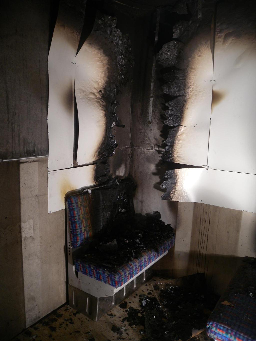
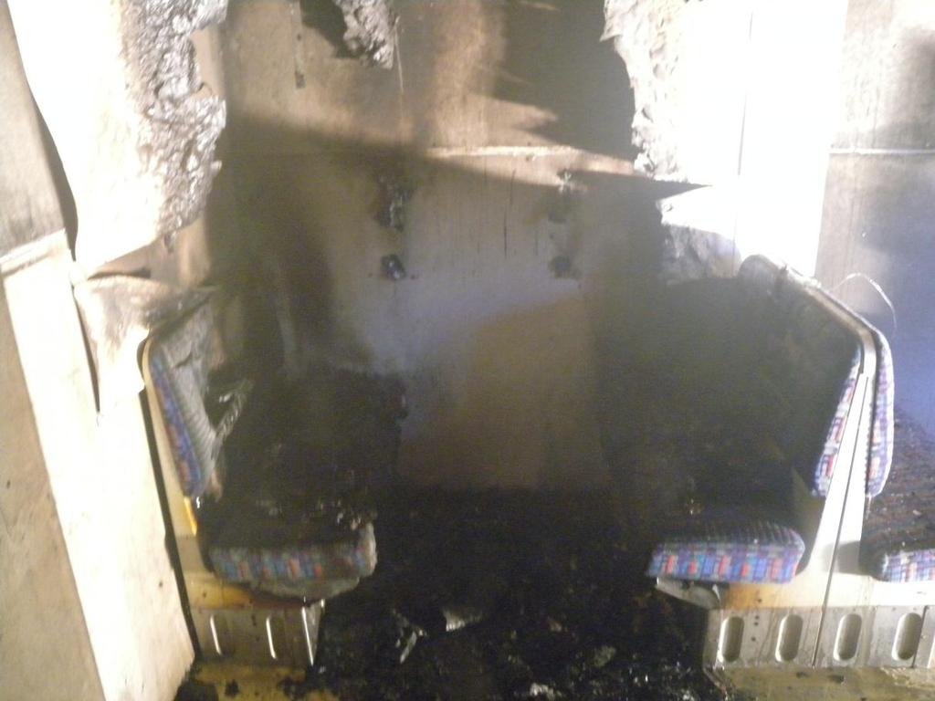
52 52 Test protocol Time [min:ss] Description -2:00 Measurements start -1:00 Video camera started 0:00 Ignition of petrol 1:46 Bags 1-4 are on fire 2:30 HPL board near the ignition source ignites 2:35 Some smoke at the side of the hood 3:42 Smoke from cabin bag (bag 5) 3:46 Seat (S3) is burning 4:29 Fire on the floor 5:36 Decreased fire in the seat were the fire was ignited 5:55 Flames only from opposite seat (S3) and floor 7:55 Decreased fire in opposite seat (S3) and on the floor 9:00 Cabin bag (bag 5) moved into the flames on the floor 9:45 Pyrolysis from the cabin bag 12:05 Cabin bag (bag 5) ignited 11:09 Half of the cabin bag (bag 5) in flames 12:48 The hole cabin bag (bag 5) in flames and pyrolysis from the seat S2 and S4. 13:47 Some fire on the floorboards surrounding the cabin bag (bag 5) 14:14 Heavy pyrolysis from the seat S2 and S4 14:26 Some fire in floorboards 14:55 Flame spread on the floor towards the seat S4. 15:32 Some flames from the seat S2 16:34 Fire in the floorboards 17:00 Decreased flames in the cabin bag (bag 5) and on the floorboards 18:54 No fire spread 25:00 Fire extinct Measurements stopped Comments Fire never reached a fully developed stage. The HPL boards have not burnt and are still mounted to wall and ceiling after extinguishment. The seat where the fire started is heavily burnt. Bag no. 1, 2, 3, 4 and 5 were completely consumed by the fire.
![53 Test 6 Test conditions Ignition source One (1) liter of petrol and four (4) fire lighters Luggage as fire load Yes, see details in table below Wood crib as fire load No Hall temperature [ C] 20.](/docs-images/91/107256166/images/53-0.jpg "8 Air flow in hall [m 3 /h] 100 000 Luggage Nr. Type of bag Weight (g) Placement 1. Backpack 8520 Seat 2. Large cabin bag 25036 Floor 3. Truck 3900 Seat 4. Sport bag 9414 Floor 5.")
53 53 Test 6 Test conditions Ignition source One (1) liter of petrol and four (4) fire lighters Luggage as fire load Yes, see details in table below Wood crib as fire load No Hall temperature [ C] 20.8 Air flow in hall [m 3 /h] Luggage Nr. Type of bag Weight (g) Placement 1. Backpack 8520 Seat 2. Large cabin bag Floor 3. Truck 3900 Seat 4. Sport bag 9414 Floor 5. Cabin bag Floor 6. Cabin bag Floor 7. Sport bag 4000 Seat 8. Backpack 2350 Seat 9. Cabin bag Floor 10. Backpack 4675 Seat 11. Backpack Seat 12. Truck bag 9210 Floor 13. Briefcase 3950 Seat 14. Sport bag 8700 Seat 15. Sport bag 7832 Floor 16. Briefcase 2790 Seat 17. Sportbag Floor 18. Backpack 4960 Floor 19. Large cabin bag Floor 20. Large cabin bag Baby carriage - -
54 54 Test protocol Time [min:ss] Description -2:00 Measurements start -1:00 Video camera started 0:00 Ignition of petrol 0:28 Bag 1 and the panel on the long side ignites 0:45 Entire corner seat burns 0:55 HPL boards on the long side is cracking 1:08 Bag 9 falls towards the fire 1:13 Burning small pieces of the ceiling panel falls down on seats and floor 1:23 A big piece of the ceiling panel falls and spreads the fire to seat (S4). Still small flames in this seat 1:30 Entire corner is in flames 1:40 Slow flame spread along the floor 1:54 Increasing fire in seat S4 2:00 The fire intensifies, smoke gets thicker, lowering smoke layer. Pyrolysis from floor outside of the direct fire 2:08 Powerful pyrolysis from floor outside of the direct fire 2:13 Flashover 2:18 Baby carriage ignites and seat S8 ignites 2:35 Total flashover 3:20 Seats S9 and S10 ignites 7:20 Fire spreads through the ceiling, Extinguishment Measurements stopped Comments A flashover occurred after about 2 min and the fire reached a fully developed stage. The fire was extinguished when the fire spread through the ceiling.
55 55 Appendix C Flame spread Flame spread in the train carriage has been estimated based on visual observations during the test and from the films from the tests. The flame spread is visualized in Figure 27 to Figure 32. The presented flame spread is a simplification and is not as regular in reality as it appears in the figures. The purpose of the figures is to see trends in the flame spread. The time dependent flame spread is visualized with red lines in a snapshot of the train carriage and the transparent yellow rectangular represent the total area that was burnt during the test. Each red line is connected to both the vertical and horizontal time axel creating a rectangular within the train carriage. The rectangle represent the flame spread at a certain time and the vertical and horizontal spread time can be read from each time axel. Figures without a time axel means that there has been very limited or no flame spread from the vicinity of the ignition source during the entire test. If the time on the time axels are shorter than the test time, this means that the flames never spread further during the test. The flame spread estimations have been made based on observations from the opening. This means that flames closer to the opening could hide spots further into the carriage that is not burning as well as seats could hide spots where it is burning. This is an uncertainty in the estimations. Figure 27. Total flame spread in test 1. Figure 28. Total flame spread in test 2.

56 56 Figure 29. Time dependent flame spread in test 3. Figure 30. Time dependent flame spread in test 4. Figure 31. Time dependent flame spread in test 5.

57 57 Figure 32. Time dependent flame spread in test 6.

58 58 Appendix D Photos from tests Test 1
59 59
60 Test 2 60
61 61
62 Test 3 62
63 63
64 Test 4 64
65 65
66 66
67 Test 5 67
68 68
69 69
70 70
71 Test 6 71
72 72
73 73


74 SP Sveriges Tekniska Forskningsinstitut SP Technical Research Institute of Sweden Our work is concentrated on innovation and the development of value-adding technology. Using Sweden's most extensive and advanced resources for technical evaluation, measurement technology, research and development, we make an important contribution to the competitiveness and sustainable development of industry. Research is carried out in close conjunction with universities and institutes of technology, to the benefit of a customer base of about 9000 organisations, ranging from start-up companies developing new technologies or new ideas to international groups. SP Technical Research Institute of Sweden Box 857, SE BORÅS, SWEDEN Telephone: , Telefax: info@sp.se, Internet: Fire Technology SP Report 2012:06 ISBN ISSN More information about publications published by SP:
Fire Spread in Large Industrial Premises and Warehouses
 Anders Lönnermark, Haukur Ingason Fire Spread in Large Industrial Premises and Warehouses BRANDFORSK project 63-21 SP Swedish National Testing and Research Institute SP Fire Technology SP REPORT 25:21
Gerd Koffmane, Henrik Hoff, AP Sensing GmbH, Böblingen
 Linear Heat Series Under Test: Extensive fire tests prove Distributed Temperature Sensing (DTS) enables fast and reliable control of fire protection systems in road and rail tunnels Gerd Koffmane, Henrik
An experimental study of the impact of tunnel suppression on tunnel ventilation
 An experimental study of the impact of tunnel suppression on tunnel ventilation Yoon J. Ko and George Hadjisophocleous Civil and Environmental Engineering, Carleton University 1125 Colonel By Drive, Ottawa,
Test One: The Uncontrolled Compartment Fire
 The University of Edinburgh BRE Centre for Fire Safety Engineering One Day Symposium on The Dalmarnock Fire Tests: Experiments & Modelling Test One: The Uncontrolled Compartment Fire Cecilia Abecassis
Full-scale fire tests with a commuter train in a tunnel
 Full-scale fire tests with a commuter train in a tunnel Anders Lönnermark, Alexander Claesson, Johan Lindström, Ying Zhen Li, Mia Kumm, Haukur Ingason SP Technical Research Institute of Sweden Fire Technology
6B-2 6th Asia-Oceania Symposium on Fire Science and Technology 17-20, March, 2004, Daegu, Korea
 6B-2 6th Asia-Oceania Symposium on Fire Science and Technology 17-20, March, 2004, Daegu, Korea CONDUCTING A FULL-SCALE EXPERIMENT ON A RAIL PASSENGER CAR ABSTRACT N. White and V.P. Dowling CSIRO Fire
ASSESSMENT OF FIRE BEHAVIOUR OF TIMBER PARTITION MATERIALS WITH A ROOM CALORIMETER
 , Volume 9, Number 1, p.38-58, 2007 ASSESSMENT OF FIRE BEHAVIOUR OF TIMBER PARTITION MATERIALS WITH A ROOM CALORIMETER C.W. Leung and W.K. Chow Department of Building Services Engineering, The Hong Kong
Fire Detection and Fire Fighting Testing and Approval on Railway Vehicles
 Fire Detection and Fire Fighting Testing and Approval on Railway Vehicles Peter Stahl Wagner Schweiz AG, Wallisellen, Switzerland Abstract Fire detection system and firefighting solutions are getting a
Large-scale fire test for interior materials of the Korean high speed train
 Copyright 2012 Tech Science Press SL, vol.7, no.1, pp.13-18, 2012 Large-scale fire test for interior materials of the Korean high speed train W.H. Park 1, D.H. Lee 1, W.S. Jung 1 Abstract: A large-scale
CHOOSING A FIRE VENTILATION STRATEGY FOR AN UNDERGROUND METRO STATION
 - 165 - CHOOSING A FIRE VENTILATION STRATEGY FOR AN UNDERGROUND METRO STATION Wojciech Węgrzyński, Grzegorz Krajewski, Paweł Sulik Fire Research Department, Building Research Institute (ITB), Poland ABSTRACT
WATER MIST FIRE PROTECTION SYSTEMS FOR INDUSTRIAL CABLE TUNNELS AND TURBINE HALLS
 WATER MIST FIRE PROTECTION SYSTEMS FOR INDUSTRIAL CABLE TUNNELS AND TURBINE HALLS Jukka Vaari 1, Amit Lior 2 1 2 VTT Technical Research Centre of Finland, Espoo, Finland Marioff Corporation Oy, Vantaa,
First Revision No. 6-NFPA [ Section No. 2.2 ]
![First Revision No. 6-NFPA [ Section No. 2.2 ]](/thumbs/77/76430292.jpg "First Revision No. 6-NFPA [ Section No. 2.2 ]") Page 1 of 18 First Revision No. 6-NFPA 555-2014 [ Section No. 2.2 ] 2.2 NFPA Publications. National Fire Protection Association, 1 Batterymarch Park, Quincy, MA 02169-7471. NFPA 12, Standard on Carbon
Page 1 of 18 First Revision No. 6-NFPA 555-2014 [ Section No. 2.2 ] 2.2 NFPA Publications. National Fire Protection Association, 1 Batterymarch Park, Quincy, MA 02169-7471. NFPA 12, Standard on Carbon
CAN THE CONE CALORIMETER BE USED TO PREDICT FULL SCALE HEAT AND SMOKE RELEASE CABLE TRAY RESULTS FROM A FULL SCALE TEST PROTOCOL?
 CAN THE CONE CALORIMETER BE USED TO PREDICT FULL SCALE HEAT AND SMOKE RELEASE CABLE TRAY RESULTS FROM A FULL SCALE TEST PROTOCOL? Marcelo M. Hirschler GBH International, USA ABSTRACT The results of three
Hot Issues in Fire Engineering 28 February 2012
 Hot Issues in Fire Engineering 28 February 2012 A Note on Cabin Fire Design for Protecting Large Halls W.K. Chow Research Centre for Fire Engineering, Department of Building Services Engineering The Hong
ASSESSMENT OF TIMBER PARTITION MATERIALS WITH FIRE RETARDANTS WITH A ROOM CALORIMETER
 , Volume 6, Number 3, p.122-154, 2004 ASSESSMENT OF TIMBER PARTITION MATERIALS WITH FIRE RETARDANTS WITH A ROOM CALORIMETER C.W. Leung, W.K. Chow Department of Building Services Engineering, The Hong Kong
Method for testing the suppression performance of fire suppression systems installed in engine compartments of buses and coaches
 2014-09-19 SP Method 4912 Method for testing the suppression performance of fire suppression systems installed in engine compartments of buses and coaches 2014-09-19 page 2 (17) Copyright This test method
Tunnel Fire Dynamics
 Tunnel Fire Dynamics Haukur Ingason Ying Zhen Li Anders Lönnermark Tunnel Fire Dynamics 1 3 Haukur Ingason Fire Research SP Technical Research Institute of Sweden Borås Sweden Anders Lönnermark Fire Research
ZONE MODEL VERIFICATION BY ELECTRIC HEATER
 , Volume 6, Number 4, p.284-290, 2004 ZONE MODEL VERIFICATION BY ELECTRIC HEATER Y.T. Chan Department of Building Services Engineering, The Hong Kong Polytechnic University, Hong Kong, China ABSTRACT Selecting
FIRE DYNAMICS IN FAÇADE FIRE TESTS: Measurement, modeling and repeatability
 Proceedings of the International Conference in Dubrovnik, 15-16 October 2015 FIRE DYNAMICS IN FAÇADE FIRE TESTS: Measurement, modeling and repeatability Johan Anderson a, Lars Boström a, Robert Jansson
ASSESSING THE FIRE PERFORMANCE OF ELECTRIC CABLES (FIPEC)
") ASSESSING THE FIRE PERFORMANCE OF ELECTRIC CABLES (FIPEC) P. Van Hees and J. Axelsson, SP Sweden, S. J. Grayson and A. M. Green, Interscience Communications UK, H Breulet, ISSeP Belgium and U Vercellotti,
ASSESSING THE FIRE PERFORMANCE OF ELECTRIC CABLES (FIPEC) P. Van Hees and J. Axelsson, SP Sweden, S. J. Grayson and A. M. Green, Interscience Communications UK, H Breulet, ISSeP Belgium and U Vercellotti,
How to Use Fire Risk Assessment Tools to Evaluate Performance Based Designs
 How to Use Fire Risk Assessment Tools to Evaluate Performance Based Designs 1 ABSTRACT Noureddine Benichou and Ahmed H. Kashef * Institute for Research in Construction National Research Council of Canada
National Fire Protection Association. 1 Batterymarch Park, Quincy, MA Phone: Fax:
 National Fire Protection Association 1 Batterymarch Park, Quincy, MA 02169-7471 Phone: 617-770-3000 Fax: 617-770-0700 www.nfpa.org MEMORANDUM To: From: NFPA Technical Committee on Internal Combustion Engines
Contact person Date Reference Page Alen Rakovic P (19) Fire Research
 Fire Research") Contact person Alen Rakovic 2015-08-28 5P05551 1 (19) Fire Research +46 10 516 51 37 Alen.Rakovic@sp.se PcP. Durk Sverige AB Ruskvädersgatan 3B 418 34 Göteborg Fire Testing of fire protection gratings
Contact person Alen Rakovic 2015-08-28 5P05551 1 (19) Fire Research +46 10 516 51 37 Alen.Rakovic@sp.se PcP. Durk Sverige AB Ruskvädersgatan 3B 418 34 Göteborg Fire Testing of fire protection gratings
Predictions of Railcar Heat Release Rates
 Predictions of Railcar Heat Release Rates John Cutonilli & Craig Beyler Hughes Associates, Inc 361 Commerce Dr, Suite 817 Baltimore, MD 21227 USA Email: jcutonilli@haifire.com, cbeyler@haifire.com KEYWORDS:
OBSERVATION ON THE TWO RECENT BUS FIRES AND PRELIMINARY RECOMMENDATIONS TO PROVIDE FIRE SAFETY
 , Volume 5, Number 1, p.1-5, 2003 OBSERVATION ON THE TWO RECENT BUS FIRES AND PRELIMINARY RECOMMENDATIONS TO PROVIDE FIRE SAFETY W.K. Chow Department of Building Services Engineering, The Hong Kong Polytechnic
Large scale fire tests with fixed fire fighting system in Runehamar tunnel
 Large scale fire tests with fixed fire fighting system in Runehamar tunnel Haukur Ingason Glenn Appel Ying Zhen Li SP Technical Research Institute of Sweden Fire Technology SP Report 214:32 Large scale
Ventilation Effects on Fire Patterns during Post Flashover Burning
 Ventilation Effects on Fire Patterns during Post Flashover Burning By Matthew Obach, M.A.Sc., EIT, CFEI In order to determine the origin of a fire, fire investigators analyze fire patterns that remain
1.0 INTRODUCTION. Shaw Industries Group 2 SwRI Project No c
 1.0 INTRODUCTION This report presents the results of a fire performance evaluation in accordance with the 2011 Edition of National Fire Protection Association (NFPA) Standard 265, Standard Methods of Fire
CFD Analysis of Fire Characteristics on Subway Junction Station
 ISGSR27 First International Symposium on Geotechnical Safety & Risk Oct. 18~19, 27 Shanghai Tongji University, China CFD Analysis of Fire Characteristics on Subway Junction Station G. H. Wu, X. Han, Q.Q.
Sprinklers Modeling for Tunnel Road Fire Fighting
 Sprinklers Modeling for Tunnel Road Fire Fighting P. Ciambelli, M.G. Meo, P. Russo, S. Vaccaro Department of Chemical and Food Engineering, University of Salerno - ITALY 1. INTRODUCTION Loss of lives and
Adrian Milford Sereca - a Jensen Hughes Company, Project Engineer Vancouver, BC, Canada
 Transit Vehicle Design Standards and Risk Analysis on Fire Development in Rapid Transit Vehicles Adrian Milford Sereca - a Jensen Hughes Company, Project Engineer Vancouver, BC, Canada Motivation Design
Simple Equations for Predicting Smoke Filling Time in Fire Rooms with Irregular Ceilings
 Fire Science and Technorogy Vol.24 No.4(2005) 165-178 165 Simple Equations for Predicting Smoke Filling Time in Fire Rooms with Irregular Ceilings Jun-ichi Yamaguchi 1, Takeyoshi Tanaka 2 1 Technical Research
Copy of article submitted to Fire Safety Engineering for publication January/February 2009
 Copy of article submitted to Fire Safety Engineering for publication January/February 2009 Metal faced sandwich panels with plastic foam cores - a challenge to fire safety by Gordon Cooke Confusion, misleading
Considerations in the Design of Smoke Management Systems for Atriums
 Construction Technology Update No. 48 Considerations in the Design of Smoke Management Systems for Atriums by G.D. Lougheed This Update discusses the use of an engineered approach to the design of smoke
TECHNICAL TRADE-OFFS USING FIXED FIRE FIGHTING SYSTEMS
 - 12 - TECHNICAL TRADE-OFFS USING FIXED FIRE FIGHTING SYSTEMS H. Ingason and Y.Z. Li, SP Technical Research Institute of Sweden ABSTRACT The increasing use of fixed fire-fighting system (FFFS) in tunnels
Intertek. REPORT NUMBER: SAT-005 ORIGINAL ISSUE DATE: October 29,2008 REVISED DATE: November 19, 2008
 Intertek I 0:: o D.. W 0:: I en w I REPORT NUMBER: 3161466SAT-005 ORIGINAL ISSUE DATE: October 29,2008 REVISED DATE: EVALUATION CENTER Intertek Testing Services NA Inc. 16015 Shady Falls Rd. Elmendorf,
RADIATION BLOCKAGE EFFECTS BY WATER CURTAIN
 , Volume 6, Number 4, p.248-254, 04 RADIATION BLOCKAGE EFFECTS BY WATER CURTAIN C.L. Choi Department of Building Services Engineering, The Hong Kong Polytechnic University, Hong Kong, China ABSTRACT Water
PREDICTING LARGE-SCALE FIRE PERFORMANCE FROM SMALL- SCALE FIRE TEST DATA
 PREDICTING LARGE-SCALE FIRE PERFORMANCE FROM SMALL- SCALE FIRE TEST DATA Marcelo M. Hirschler * And Marc L. Janssens ** * GBH International ** Univ. North Carolina @ Charlotte OVERALL OUTLINE Predictive
NECESSITY OF CARRYING OUT FULL-SCALE BURNING TESTS FOR POST-FLASHOVER RETAIL SHOP FIRES
 , Volume 5, Number 1, p.20-27, 2003 NECESSITY OF CARRYING OUT FULL-SCALE BURNING TESTS FOR POST-FLASHOVER RETAIL SHOP FIRES W.K. Chow Department of Building Services Engineering, The Hong Kong Polytechnic
UPHOLSTERED FURNITURE AND MATTRESSES IN NEW AND EXISTING BUILDINGS
 Page 20 ABOUT CODE CORNER CCFS would like to remind you to check with your local Authority Having Jurisdiction (AHJ) for questions and opinions concerning your local Fire and Building Codes. The information
Study of Numerical Analysis on Smoke Exhaust Performance of Portable Smoke Exhaust Fan
 Open Journal of Fluid Dynamics, 2017, 7, 205-218 http://www.scirp.org/journal/ojfd ISSN Online: 2165-3860 ISSN Print: 2165-3852 Study of Numerical Analysis on Smoke Exhaust Performance of Portable Smoke
Smoldering Propagation Characteristics of Flexible Polyurethane Foam under Different Air Flow Rates
 Smoldering Propagation Characteristics of Flexible Polyurethane Foam under Different Air Flow Rates Zhou Y., Fei Y.*, Hu S. Q. Nanjing Tech University, College of Fire Safety Science and Engineering &
Guideline No 7:2005. European Guideline. Safety distances between waste containers and buildings. CFPA-E -Guidelines
 Guideline No 7:2005 European Guideline Safety distances between waste containers and buildings CFPA-E -Guidelines Guideline No 7:2005 FOREWORD The European fire protection associations have decided to
The first tunnel fire. Benefits of fire
 Benefits of fire suppression Quantifying the effects of suppression on energy release. This article by Fathi Tarada, managing director of fire safety, risk management, ventilation and CFD consultant Mosen
IFireSS International Fire Safety Symposium Coimbra, Portugal, 20 th -22 nd April 2015
 IFireSS International Fire Safety Symposium Coimbra, Portugal, 20 th -22 nd April 2015 SCALE MODEL EXPERIMENTS ON SMOKE MOVEMENT IN A TILTED TUNNEL photo Author 1 30 mm 40 mm photo Author 2 30 mm 40 mm
Overview of the PRISME project Technical Description and Main Outcomes
 OECD PRISME Project on Fire Propagation Final Seminar Overview of the PRISME project Technical Description and Main Outcomes Audouin L., Rigollet L., Pretrel H., Le Saux W. IRSN / ETIC Summary (1) Context
Underground fires in metro systems failures, accidents and terrorism
 Underground fires in metro systems failures, accidents and terrorism Dr Fathi Tarada Mosen Ltd RIFA Seminar 22-03-2018 Issues Higher threat of fire & explosions in congested underground metro stations?
SOLIT PROJECT: WATER MIST FIRE SUPPRESSION SYSTEMS AS PART OF THE TUNNEL SAFETY SYSTEM
 - 157 - SOLIT PROJECT: WATER MIST FIRE SUPPRESSION SYSTEMS AS PART OF THE TUNNEL SAFETY SYSTEM Kratzmeir S. FOGTEC Fire Protection, Research & Development, Germany Keywords: Fire Protection, Fire suppression,
PRELIMINARY ANALYSIS OF THE NUMBER OF OCCUPANTS, FIRE GROWTH, DETECTION TIMES AND PRE-MOVEMENT TIMES FOR PROBABILISTIC RISK ASSESSMENT
 PRELIMINARY ANALYSIS OF THE NUMBER OF OCCUPANTS, FIRE GROWTH, DETECTION TIMES AND PRE-MOVEMENT TIMES FOR PROBABILISTIC RISK ASSESSMENT DAVID CHARTERS DEAN MCGRAIL Arup Fire, 78 East Street, Leeds, LS9
NUMERICAL STUDIES ON BARE CABIN FIRES WITH OPERATION OF SMOKE EXTRACTION SYSTEM
 , Volume 11, Number 2, p.43-48, 2012 NUMERICAL STUDIES ON BARE CABIN FIRES WITH OPERATION OF SMOKE EXTRACTION SYSTEM Q. Kui Institute of Building Fire Research, China Academy of Building Research, Beijing,
Experimental Study to Evaluate Smoke Stratification and Layer Height in Highly Ventilated Compartments
 Experimental Study to Evaluate Smoke Stratification and Layer Height in Highly Ventilated Compartments Jason Huczek a, Marc Janssens a, Kentaro Onaka b, Stephen Turner c a SwRI, 6220 Culebra Road, San
Safety distance between waste containers and buildings. CFPA-E Guideline No 7:2011 F
 Safety distance between waste containers and buildings CFPA-E Guideline No 7:2011 F FOREWORD The European fire protection associations have decided to produce common guidelines in order to achieve similar
Numerical investigation on the effect of channelled and unchannelled screens on smoke contamination in atriums upper balconies with open upstand
 Numerical investigation on the effect of channelled and unchannelled screens on smoke contamination in atriums upper balconies with open upstand Mohammed Mutafi 1, Mohammad Nasif 1*, William Pao 1 and
SCALE MODEL STUDIES ON SMOKE MOVEMENT IN INCLINED TUNNEL WITH LONGITUDINAL VENTILATION AND SMOKE BARRIERS
 , Volume 11, Number 2, p.21-26, 212 SCALE MODEL STUDIES ON SMOKE MOVEMENT IN INCLINED TUNNEL WITH LONGITUDINAL VENTILATION AND SMOKE BARRIERS C.Y. Tso and W.K. Chow Research Centre for Fire Engineering,
Development of a test method for fire detection in road tunnels
 Development of a test method for fire detection in road tunnels SP Technical Research Institute of Sweden Haukur Ingason Glenn Appel Jonatan Gehandler Ying Zhen Li Hans Nyman Peter Karlsson Magnus Arvidson
Fike set out to develop a better understanding of the power density trends in data centers around the world.
 Fike set out to develop a better understanding of the power density trends in data centers around the world. We wanted to learn how increasing power density translates into energy augmented combustion.
NUMERICAL SIMULATION OF THE NEW SOUTH WALES FIRE BRIGADE COMPARTMENT FIRE BEHAVIOUR TRAINING TEST CELL
 , Volume 9, Number 4, p.154-162, 7 NUMERICAL SIMULATION OF THE NEW SOUTH WALES FIRE BRIGADE COMPARTMENT FIRE BEHAVIOUR TRAINING TEST CELL D. Mackay and T. Barber School of Mechanical and Manufacturing
RESEARCH TECHNICAL REPORT. SMART Sprinkler Protection for Highly Challenging Fires - Phase 2: Full-Scale Fire Tests in Rack Storage
 RESEARCH TECHNICAL REPORT SMART Sprinkler Protection for Highly Challenging Fires - Phase 2: Full-Scale Fire Tests in Rack Storage SMART Sprinkler Protection for Highly Challenging Fires - Phase 2: Full-Scale
An Analysis of Compartment Fire and Induced Smoke Movement in Adjacent Corridor
 2C-1 6th Asia-Oceania Symposium on Fire Science and Technology 17-20, March, 2004, Daegu, Korea An Analysis of Compartment Fire and Induced Smoke Movement in Adjacent Corridor Soo-Young Kim *, Eung-Sik
EPSRC Research Project: Real Fires for the Safe Design of Tall Buildings
 EPSRC Research Project: Real Fires for the Safe Design of Tall Buildings Prof Luke Bisby, Acting Director BRE Centre for Fire Safety Engineering Arup Chair of Fire and Structures BRE Centre for Fire Safety
Experimental Room Fire Studies with Perforated Suspended Ceiling
 Experimental Room Fire Studies with Perforated Suspended Ceiling FIONA S.C. TSUI 1, W.K. CHOW 1, N.K. FONG 1, Y. GAO 2, H. DONG 2, and G.W. ZOU 2 1 Research Centre for Fire Engineering Department of Building
FULL-SCALE FIRE TESTS OF A TWO-STORY CROSS-LAMINATED TIMBER STRUCTURE
 FULL-SCALE FIRE TESTS OF A TWO-STORY CROSS-LAMINATED TIMBER STRUCTURE Laura E. Hasburgh 1, Samuel L. Zelinka 1, Keith J. Bourne 1, David R. Tucholski 2, Jason P. Ouellette 2 ABSTRACT: There is a current
Case Study of Underground Car Park. Team Japan
 11th Conference on Performance Based Codes and Fire Safety Design Methods Case Study of Underground Car Park Team Japan We focused on the characteristics of the fire behavior of car fire. Car fire is not
CERBERUS: A NEW MODEL TO ESTIMATE SIZE AND SPREAD FOR FIRES IN TUNNELS WITH LONGITUDINAL VENTILATION
 - 69 - CERBERUS: A NEW MODEL TO ESTIMATE SIZE AND SPREAD FOR FIRES IN TUNNELS WITH LONGITUDINAL VENTILATION R.O. Carvel, A.N. Beard & P.W. Jowitt Department of Civil and Offshore Engineering, Heriot-Watt
OPTIMIZATION OF VENTILATION MODE OF SMOKE CONTROL SYSTEM IN HIGH-RISE BUILDING FIRE
 OPTIMIZATION OF VENTILATION MODE OF SMOKE CONTROL SYSTEM IN HIGH-RISE BUILDING FIRE 1 RU ZHOU, 2 WEI ZHANG 1 School of Urban Construction and Safety Engineering, Nanjing University of Technology, Nanjing
CFD ASSESSMENT OF RAILWAY TUNNEL TRAIN FIRE SCENARIOS
 CFD ASSESSMENT OF RAILWAY TUNNEL TRAIN FIRE SCENARIOS Yunlong Liu*, Xijuan Liu and Bradley Paroz Fire Science and Technology Laboratory CSIRO Manufacturing and Infrastructure Technology PO Box 310 North
Probabilistic-deterministic modelling of fire spread
 European Journal of Environmental and Safety Sciences 2014 2(2): 79-83 ISSN 1339-472X European Science and Research Institute (Original Research Paper) Probabilistic-deterministic modelling of fire spread
FULL-SCALE BURNING TESTS FOR RETAIL SHOP FIRES: PRELIMINARY STUDIES
 , Volume 6, Number 3, p.94-121, 24 FULL-SCALE BURNING TESTS FOR RETAIL SHOP FIRES: PRELIMINARY STUDIES W.K. Chow and Candy M.Y. Ng Department of Building Services Engineering, The Hong Kong Polytechnic
PRELIMINARY EXPERIMENTAL STUDY OF DOUBLE-SKINNED FAÇADE
 , Volume 6, Number 3, p.155-167, 2004 PRELIMINARY EXPERIMENTAL STUDY OF DOUBLE-SKINNED FAÇADE W.K. Chow and W.Y. Hung Department of Building Services Engineering, The Hong Kong Polytechnic University,
M E M O R A N D U M. Diane Matthews, Administrator, Technical Projects. NFPA 101 First Draft Letter Ballot (A2014)
") National Fire Protection Association 1 Batterymarch Park, Quincy, MA 02169 7471 Phone: 617 770 3000 Fax: 617 770 0700 www.nfpa.org M E M O R A N D U M TO: FROM: NFPA Technical Committee on Furnishings
National Fire Protection Association 1 Batterymarch Park, Quincy, MA 02169 7471 Phone: 617 770 3000 Fax: 617 770 0700 www.nfpa.org M E M O R A N D U M TO: FROM: NFPA Technical Committee on Furnishings
MINISTERIO DE FOMENTO
 Dirección General de Servicios de Alta Velocidad - Larga Distancia Real Scale Fire Tests in High-Speed Trains Convocatoria de Concesión de Ayudas a Agrupaciones o Consorcios de Investigación para la realización
Available online at ScienceDirect. Procedia Engineering 84 (2014 )
") Available online at www.sciencedirect.com ScienceDirect Procedia Engineering 84 (2014 ) 553 557 2014ISSST, 2014 International Symposium on Safety Science and Technology Research on fire endurance of tempered
Available online at www.sciencedirect.com ScienceDirect Procedia Engineering 84 (2014 ) 553 557 2014ISSST, 2014 International Symposium on Safety Science and Technology Research on fire endurance of tempered
Water-mist systems for fire-protection of saunas
 17 th International Water Mist Conference 25 26 October 2017 Rome, Italy Paolo E. Santangelo 1, Luca Tarozzi 2, Massimiliano Bettati 2, Paolo Tartarini 1 1 Dipartimento di Ingegneria Enzo Ferrari Università
Analysis of the influence of open door size on fire smoke diffusion law in protective engineering
 Analysis of the influence of open door size on fire smoke diffusion law in protective engineering Abstract Zheli Xing a, Jinfeng Mao b, Chaofeng Li c and Jin Zhou d PLA University of Science and Technology,
INFLUENCE OF SOLAR RADIATION AND VENTILATION CONDITIONS ON HEAT BALANCE AND THERMAL COMFORT CONDITIONS IN LIVING-ROOMS
 INFLUENCE OF SOLAR RADIATION AND VENTILATION CONDITIONS ON HEAT BALANCE AND THERMAL COMFORT CONDITIONS IN LIVING-ROOMS Staņislavs GENDELIS, Andris JAKOVIČS Laboratory for mathematical modelling of environmental
GUIDELINES FOR THE APPROVAL OF EQUIVALENT FIXED GAS FIRE-EXTINGUISHING SYSTEMS, AS REFERRED TO IN SOLAS 74, FOR MACHINERY SPACES AND CARGO PUMP-ROOMS
 12 December 1996 Ref. T4/4.01 GUIDELINES FOR THE APPROVAL OF EQUIVALENT FIXED GAS FIRE-EXTINGUISHING SYSTEMS, AS REFERRED TO IN SOLAS 74, FOR MACHINERY SPACES AND CARGO PUMP-ROOMS 1 The Maritime Safety
Fire protection of emergency electrical devices: effect on the level of risk a case study of a rail tunnel
 Safety and Security Engineering VI 73 Fire protection of emergency electrical devices: effect on the level of risk a case study of a rail tunnel M. Lombardi & G. Rossi Dipartimento di Ingegneria Chimica
BUS FIRE SAFETY Michael Försth. Fire Research. RISE Research Institutes of Sweden
 BUS FIRE SAFETY 2018-01-29 Michael Försth RISE Research Institutes of Sweden Fire Research Three have become one - RISE The RISE institutes Innventia, SP and Swedish ICT have merged in order to become
Recent BRANZFIRE enhancements and validation
 Recent BRANZFIRE enhancements and validation Michael Spearpoint University of Canterbury Summary BRANZFIRE is a multi-compartment fire zone model that has been under development since 1996 predominately
STACK EFFECT IN LIGHT WELL OF HIGH RISE APARTMENT BUILDING
 STACK EFFECT IN LIGHT WELL OF HIGH RISE APARTMENT BUILDING H. Kotani, R. Satoh, T. Yamanaka Dept. of Architectural Engineering, School of Engineering, Osaka University, Osaka, Japan ABSTRACT The purpose
Heat Release Rate of an Open Kitchen Fire of Small Residential Units in Tall Buildings
 2014 Purdue Compressor/Refrigeration and Air Conditioning and High Performance Buildings Conference West Lafayette, IN, USA 14-17 July 2014 Heat Release Rate of an Open Kitchen Fire of Small Residential
A Comparison of Carbon Monoxide Gas Sensing to Particle Smoke Detection in Residential Fire Scenarios
 A Comparison of Carbon Monoxide Gas Sensing to Particle Smoke Detection in Residential Fire Scenarios Thomas Cleary, Amy Mensch National Institute of Standards and Technology, Gaithersburg, MD, USA Abstract
BUILDING FIRE SAFETY AND HAZARD ASSESSMENT METHODS FOR COMBUSTIBLE SURFACE FINISHES C.A. WADE
 CIB World Building Congress, April 21, Wellington, New Zealand Page 1 of 11 BUILDING FIRE SAFETY AND HAZARD ASSESSMENT METHODS FOR COMBUSTIBLE SURFACE FINISHES C.A. WADE Building Research Association of
Hot Issues in Fire Engineering 12 March 2013
 Hot Issues in Fire Engineering 12 March 2013 An Update on Design Fires of Vehicular Tunnels W.K. Chow Fellow, Hong Kong Academy of Engineering Sciences Research Centre for Fire Engineering, Department
LESSON ONE FIREFIGHTER I Fire Behavior
 LESSON ONE FIREFIGHTER I Fire Behavior OBJECTIVE PAGE DOMAIN: COGNITIVE LEVEL OF LEARNING: KNOWLEDGE MATERIALS IFSTA Essentials 4th edition; overhead projector or laptop computer and multi media projector;
GTR#13: towards inherently safer hydrogen-powered vehicles
 GTR#13: towards inherently safer hydrogen-powered vehicles Prof Vladimir Molkov Recent advances by Hydrogen Safety Engineering and Research Centre (HySAFER) ulster.ac.uk Outline of presentation Fire test
COMPARISON OF CFD MODELLING WITH FIRE TESTS Comparison of CFD Modelling with Results of Full Scale Compartment Fire Tests in a Residential Unit
 Application of Structural Fire Engineering, 19-20 April 2013, Prague, Czech Republic COMPARISON OF CFD MODELLING WITH FIRE TESTS Comparison of CFD Modelling with Results of Full Scale Compartment Fire
Fire Resistance - Implications for regulations and standards of the September 11th terrorist attacks on the world trade centre Tom Lennon, FRS, BRE
 Fire Resistance - Implications for regulations and standards of the September 11th terrorist attacks on the world trade centre Tom Lennon, FRS, BRE Malaysia May 2003 Questions What is fire resistance?
A study for a fire spread mechanism of residential buildings with numerical modeling
 Safety and Security Engineering IV 185 A study for a fire spread mechanism of residential buildings with numerical modeling C.-S. Ahn & J.-Y. Kim Fire Safety Research Division, Korea Institute of Construction
TUNPROTEC. Active Tunnel Fire Protection
 VID FIre KIll TUNPROTEC Active Tunnel Fire Protection 9 An Active Tunnel Fire General The tunnel structures are very valuable. Infrastructure tunnels, such as train tunnels and road tunnels represent very
Advantages and Disadvantages of Fire Modelling
 Advantages and Disadvantages of Fire Modelling Dr Guillermo Rein School of Engineering University of Edinburgh & Imperial College London Dr Guillermo Rein 9 May 2012 Chief Fire Officers Association Annual
Behaviour of an Intumescing System Subjected to Different Heating Conditions. Johansson, Nils; Van Hees, Patrick; Jansson, Robert; Sjöström, Johan
 Behaviour of an Intumescing System Subjected to Different Heating Conditions Johansson, Nils; Van Hees, Patrick; Jansson, Robert; Sjöström, Johan Published in: Fire and Materials - 13th International Conferance
A SURVEY OF OCCUPANT RESPONSE TOWARDS AN AUDIBLE FIRE ALARM
 Int. Journal for Housing Science, Vol.33, No.4 pp. 249-258, 2009 Published in the United States A SURVEY OF OCCUPANT RESPONSE TOWARDS AN AUDIBLE FIRE ALARM L. T. Wong, N. K. Fong and W. H. Sui Department
FINDINGS FROM FIRE TESTS IN TUNNEL CONSTRUCTIONS WITH VENTILATION SYSTEMS AND FIXED FIRE SUPPRESSION SYSTEMS
 - 203 - FINDINGS FROM FIRE TESTS IN TUNNEL CONSTRUCTIONS WITH VENTILATION SYSTEMS AND FIXED FIRE SUPPRESSION SYSTEMS Hofer R., IBS Institute for Technical Fire Protection and Safety Research, Linz / Austria
FM Approval Standard For Cavity Walls And Rainscreens
 FM4411 - Approval Standard For Cavity Walls And Rainscreens Mark D. Tyrol, P.E. FM Approvals Air Barrier Association of America (ABAA) is a Registered Provider with The American Institute of Architects
LABORATORY STUDY ON THE CONSOLIDATION SETTLEMENT OF CLAY-FILLED GEOTEXTILE TUBE AND BAGS
 Journal of GeoEngineering, Vol. 6, No. 1, pp. Chew 41-45, et al.: April Laboratory 2011 Study on the Consolidation Settlement of Clay-Filled Geotextile Tube and Bags 41 LABORATORY STUDY ON THE CONSOLIDATION
Numerical Simulation of Fluid Flow and Heat Transfer in a Water Heater
 Numerical Simulation of Fluid Flow and Heat Transfer in a Water Heater MIRCEA NICOARĂ mircea.nicoara@mec.upt.ro AUREL RĂDUłĂ aurel.raduta@mec.upt.ro LAURENłIU ROLAND CUCURUZ roland.cucuruz@mec.upt.ro COSMIN
OIL AND GAS INDUSTRY
 FIRED HEATER DESIGN This case study demonstrates the implementation of an API 560 fired heater compound component in Flownex. It also shows how Flownex has been used during the process design and preliminary
Residential Building Walls and Environment in Amman, Jordan
 Int. J. of Thermal & Environmental Engineering Volume 3, No. 2 (211) 1-7 Residential Building Walls and Environment in Amman, Jordan S. J. Sulaiman*, N. Beithou Department of Mechanical Engineering, Applied
5B-3 6th Asia-Oceania Symposium on Fire Science and Technology 17-20, March, 2004, Daegu, Korea
 5B-3 6th Asia-Oceania Symposium on Fire Science and Technology 17-20, March, 2004, Daegu, Korea PRACTICAL APPLICATIONS OF FIRE MODELING IN INDUSTRIAL APPLICATIONS By James M. Dewey, Advisor Risk Management