User Manual & Setting Instructions
|
|
|
- Ernest McDowell
- 5 years ago
- Views:
Transcription
1 WT-9001 IP65 GSM Remote Moniitoriing And Remote Controll System User Manual & Setting Instructions WWIITT UU RR AA CCOORR PPOORR AA TT IIOO NN SSDD NN BBHH DD

2 WIRING DIAGRAM DESCRIPTION 2
3 CONNECTION DETAILS 3


4 4
5 PACKAGE CONTENTS 1) 1 pc IP65 Enclosure 2) 1 pc WT-9001 Main Board with GSM Module mounted 3) 1 pc Power Adapter 4) 1 pc Battery Backup 5) 1 pc GSM Antenna 6) 1 pc LCD Display for Assisting in Programming CONTENTS 1. Introduction 6 2. Features 6 3. Characteristic 6 4. Installation Instructions WT-9001 IP65 Programming Instructions Programming the Administrator Numbers Access Control for Administrator Output Settings Input Settings Alarm Settings GPRS Settings Miscellaneous Settings Technical Specifications 35 5
6 1. INTRODUCTION The WT9001 IP65 GSM Remote Monitoring & Remote Control System is a complete remote telemetry unit. It contains a GSM Modem and control circuitry. It is capable of controlling up to 8 Relay outputs and monitor 8 Digital inputs and 4 Analogue inputs. (Analogue input support: Detect Water Leaks, Monitor Temperatures for out-of-range conditions, Monitor Humidity for Damaging High Humidity Levels and monitor fuel levels). The WT9001 IP65 GSM Remote Monitoring & Remote Control System is operated by the sending of SMS, GPRS and . The GSM controller can be used as a remote telemetry system; users can directly control the output relays from a simple text message or GPRS. The controller can also be used as a remote monitoring system; the unit can automatically notify the user whenever the any inputs change state. The WT-9001 IP65 is complete with an LCD display, back up battery and built-in Quad- Band Modem. 2. FEATURES Monitors up to 8 Digital inputs & 4 Analogue inputs 8 Remote control outputs for switching applications Fast and easy installation Low set up and running costs No field programming required as it can be done by SMS Faster response to alarms and process disturbances Able to work in GSM mode or GPRS mode Programmable 4 alarm set points for each analogue input Works with 0 5VDC or 4 20mA based transducer Accept other kind of sensors temperature sensor, motion sensor etc. Reports on set point alarms and other triggers Real-time monitoring & controlling via monitoring software Reduces wasted traveling time responding to alarm events Provides more detailed information 3. CHARACTERISTIC WT-9001 is a versatile SMS alert device suited for most monitoring needs. It is simple to use yet is packed with powerful functionalities to meet a wide ranging industrial and commercial and residential applications 6
7 3.1 Standalone Operation Housed in the weather and desk proof IP 65 enclosure complete with internal industrial modem, monitoring controller and flexible operating firmware. It is very easy to setup, install and use Digital Inputs Most equipment today does provide some form of alerting signal to interface to monitoring devices from reporting of various malfunction or abnormalities. There are various kinds of signal that the equipment can send out, most common of which are opening or closure of one or more switch relay contact. UPS usually provide signals such as incoming power fail, battery mode, battery level low, and switchover failure. An air conditioner system may provide signals such as system on/ off, compressor over temperature, low gas pressure, etc. Equipments to be monitored are connected to WT-9001 using these alarm signaling contacts. WT-9001 keeps a constant watch over all the contacts. Whenever any contact input changes status (either from a close to open or from an open state to close state) it is captured by WT It will then process the input according to the configuration provided by the user. The correct SMS messages will be sent to 20 mobile phone users. WT-9001 is so fast in capturing the change of status of any signaling contacts that no event will be missed out up to 8 inputs can be monitored directly. The flexibility of WT is in allowing remote query of input status using SMS. To change contacting mobile phone number is also very easy. Authorize personal remotely using SMS command to add, change or delete mobile phone number in WT Analogue Inputs The WT-9001 has 4 analogue inputs that can be configured to measure a 4 20mA signal or 0 5VDC signal. It will generate reports when the monitored signal reaches the programmable set points. Four programmable set points can be programmed for each analogue input. When the monitored signal crosses a set point a specified action will be performed like switching the output relay or sending an SMS report. 7
8 3.4 8 Digital Outputs WT-9001 is a 2 way device. Besides monitoring inputs and act upon such inputs it also allow mobile phone users to compose SMS messages to it. When WT-9001 receives any SMS, it will look its memory bank to see what it is supposed to do and action according. No action SMS are ignored. Up to 8 relays can turned on and off by messages received from mobile phone. Creating action messages are done with the same ease as that of input monitoring 3.5 Querying Inputs And Outputs Status Authorized groups can also query the status of an input or output. This is very useful feature to determine the present status of an input or output. The enquirer need not wait for an alarm to happen in order to receive the given I/O status. 3.6 Turning On/ Off Device Remotely Authorized users can send a SMS command to trigger on or off the digital output. Upon receiving the command, WT-9001 will perform the instructed action. After the on or off action is done, it will send a reply to the querying mobile phone as an acknowledgement, There are 8 digital output that can be independently controlled. 3.7 Remote Editing Of Mobile Phone Numbers WT-9001 has a feature to allow user to remotely add, change or delete any mobile phone numbers in WT-9001 memory. Re-assigning of operation personnel, a change of mobiles phone number is also common. Rather than having to physically go to the installation site with a notebook computer, the authorized personnel can perform the change from anywhere using mobile phone. Where there are many installed sites, this feature saves time and afford. 3.8 System Check Authorized mobile phone group can perform system check by sending a command to WT If WT-9001 is switched on or working normally, it will reply to the querying number. 8
9 3.9 GSM Modem Integral to the design of WT-9001 is a GSM 850/900/1800/1900mhz Industrial grade modem. Its capabilities and performance are highly optimized by the operating firmware. Any change in the GSM signal and receiving conditions are detected quickly and the software automatically takes care of signal errors 3.10 Reliable Performance Besides running the necessary program to perform all the required functions, WT-9001 has diagnostic routines running alongside. Being a monitoring device, WT-9001 must have a very high operating reliability and stability. Every section of WT-9001 is monitoring each other. Should the modem fail to perform its required role, the controller will interrogate and restart the modem Application For monitoring and remote control of equipments and machines that are able to provide dry contract signals. 8 digital outputs with pulse functions extend control functions. Suitable for door access control, On/Off equipment remotely, resetting of Routers, Network switches etc. Some application examples are: - Machines, Standby Power Generator, Electrical Panels, Pumps, Uninterruptable Power Supplies, DC rectifier systems, Vending Machines, Fire Alarm Panels, Gas Monitoring Systems, ATM Machines, Security Systems, Fishery, Cold rooms, HVAC systems, Door Security, Network equipment and more. 9


10 4. INSTALLATION INSTRUCTION Note: It is essential that you read the step by step instructions fully prior to installing and programming the unit 4.1 Screw off the Front Case of WT-9001 IP65 Main Unit 4.2 Installing the Components: Antenna, LCD, Power Supply & SIM Card Installing the SIM Card Note: Installing the SIM Card. Please be sure the initial 4 digit PIN code of SIM card is disabled. This can be done by placing it in an unlocked Mobile phone and first checking if the SIM requested any PIN code. If this is the case the PIN code can be disabled using the security settings on the phone. The WT-9001 identifies only 3V SIM Card. Proceed as follows 1. Slide back the SIM door and lift it up 2. Slide the SIM card into the SIM door making sure that the clipped corner of the SIM card lines up with the clipped corner of the SIM holder 3. Close the SIM door 10
11 4. Slide the SIM door to lock the SIM card in place You should install the WT-9001 in a place where there is GSM signal coming from the operator you want to use. Check it with a phone before proceeding with the installation. If you need to install the device in a place with little signal, you may consider using an external antenna that we may supply as an option to be purchased separately with 5m cable. 5. WT-9001 IP65 PROGRAMMING INSTRUCTIONS (via SMS Only) You can program the WT-9001 via SMS commands using your phone. Any programming command sent by SMS can be in SMALL or CAPITAL letters. The fields between square brackets are parameters; do NOT enter the square brackets. When you send a command, you will receive the answer for the first time even if your GSM number is not in the administrator list. This happens because the WT-9001 recognizes any GSM number as administrator and answers to it. Attention: Please program the WT-9001 unit systematically begin with programming the administrator number. 5.1 Programming the Administrator Number The 20 administrator numbers can be programmed with a text command via SMS. *TEL[N]#XXXXXXXXXX N stands for administrator number 1 20 XXXXXXXXXX stands for the phone number you want to program as administrator. Please note that it is possible to program up to a maximum of 16 digits for a phone number. To program phone number as administrator into list number 1, you would send the following SMS command to the unit. *TEL1# Example of Returned Message: TEL1=
12 Note: Programming the administrator numbers is necessary in order to operate all other functions and to receive text alerts when the relays activated. 5.2 Access Control For Administrator Note: It is advised that the owner should set the system to allow programming access for administrators only after programming the Administrator numbers. Sending SMS Command: *ANY?#1 Only the administrators in the list will have the access control to the system, any person outside the list in this case will not have the authority to access the system and text command sent to the system will be rejected. To allow any person gain access to the system just send SMS Command: *ANY?#0 Note: Only Administrator number 1 and 2 may send this SMS command 5.3 OUTPUT Settings The WT-9001 has 8 outputs that are connected to an on-board relay which can be activated by sending an SMS command Switch On the Output Relay For a Specific Time To activate any output relay, you can send a text command via SMS specifying the output number and the number of seconds the output should stay on to the unit. It is possible to set up to maximum of 99,999 seconds *RLY[N]#X N stands for Output number 1-8 X stands for the number of seconds. Range from To turn on the output relay number 5 for 1 hour, you can send the following text message to the unit. *RLY5#3600 Example of Returned Message: *RLY5=3600 OK 12
13 Note: Sending the following SMS Message to unit will switch off the relay *RLY5#0 To check the status of all the relays, you would send the following text message to the unit. *RLY?# Switch Multiple Outputs Relays to Stay On To activate multiple output relays to stay on, you can send a text command via SMS specifying the output number that should stay on to the unit. *RLNU#XXXXXXXX XXXXXXXX stands for 8 digits value: ON (1) or OFF (0) for the 8 Outputs To switch on the output relay number 5, 6, 7, 8, you can send the following text message to the unit. *RLNU# Sending the following SMS Message to unit would mean all the relays will be switched off. *RLNU# The 1 indicates the ON command and the 0 (zero) indicates the OFF command Setting the Recipient of Relay Off Alert The unit can generate text alerts to all 8 of the administrator s Mobile phone numbers when the relay has turned on or off. To set the administrator to receive this alert, you would send the following commands by SMS message to the unit. *RETR#XXXXXXXXXXXXXXXXXXXX X stands for position for 1-20 administrators with function value: 0 (OFF), 1 9 (number of SMS alerts) 13
14 To program the unit to generate 2 SMS to administrators 1, 2, 3, 4, 5 and 1 SMS to the rest, you would send the following SMS message to the unit. *RETR# Example of Returned Message: RETR= To check the setting, you can send the following SMS command to the unit. *RETR?# 5.4 INPUT SETTINGS One of the most important functions of WT-9001 is to receive alarms. In order to use this function, you must turn on the function of the inputs and tell the WT-9001 which are the recipient numbers and who should receive the alert message for the particular input Turn On the Function of Inputs To turn on the function of input, you can send the following commands by SMS message to the unit. *CTR[N]#X N stands for number 1-12 of Input (Analogue Input 1 4, Digital Input 5 12) X stands for ON (1) or OFF (0) value To turn on input number 1, you can send the following text message to the unit. *CTR1#1 Returned Message: #INCTR1=ON OK To disable input 1, you would send the following SMS to the unit. *CTR1#0 Returned Message: #INCTR1=OFF OK 14
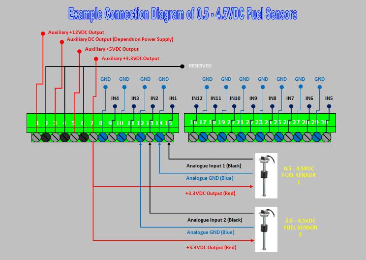
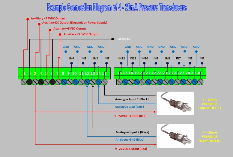
15 Note: A disabled input will not trigger an alarm or report Setup the Working Mode of 4 Analogue Inputs Input 1, 2, 3 and 4 of WT-9001 can be configured to an analogue inputs signal. When the inputs is configured as an analogue input, it can measure a 4 20mA input signal or 0 5VDC signal and will generate report when the monitored signal reaches the programmable set points. To setup the working mode of input, you can send the following command by SMS message to the unit. *SWT[N]#X N stands for input number 1-4 X stands for Working Mode 1, 2, 3 and 4 Description: Working Mode 1: Function as Analogue Input (Measure 0 3.3VDC Signal) for voltage based transducer Working Mode 2: Function as Analogue Input (Measure 4 20mA Signal) for current based transducer Working Mode 3: Function as Analogue Input for temperature Working Mode 4: Function as Analogue Input for humidity To configure input 1 to monitor a 4 20mA input signal, you would send the following SMS message to the unit. *SWT1#2 Note: Loop voltage of +3.3VDC, +5VDC and +12VDC output is included on-board to provide power for up to four 0 5VDC sensors or 4 20mA sensors. A maximum of +24VDC is allowed to be connected to the inputs Setting the Alarm Set Points for Analogue Input Note: This Function Works On Analogue Input Only There are 4 alarm set points available on each analogue input. It allows the unit to generate alarms whenever the monitored signal reaches the set point. To program the alarm set points, you can send the following command by SMS to the unit. *ALP[N][I]#XX,F 15
16 N stands for input number 1 4 I stands for set point number 1 4 XX stands for 2 digits Percentage Threshold Alert Value for Alarm F stands for the perform functions (Selectable) 0 10 Selectable Functions (F) Description: Function 0: No Function Function 1: Activates output relay 5 to stay on Function 2: Activates output relay 6 to stay on Function 3: Activates output relay 7 to stay on Function 4: Activates output relay 8 to stay on Function 5: Sends a programmable alert message (*SDF[N]#) Function 6: Sends a programmable alert message (*SDF[N]#) and activates audible alarm (Depends on function *ALM#) Function 7: Turn off output relay 5. The unit will send SMS if the relay 5 is ON at previous state. If not it won t send SMS. Function 8: Turn off output relay 6. The unit will send SMS if the relay 6 is ON at previous state. If not it won t send SMS. Function 9: Turn off output relay 7. The unit will send SMS if the relay 7 is ON at previous state. If not it won t send SMS. 16
17 Function 10: Turn off output relay 8. The unit will send SMS if the relay 8 is ON at previous state. If not it won t send SMS. To setup 2 alarm set points at 10% and 90% for input 1 and both set points will also trigger an alarm message; you would send the 2 following SMS command to the unit. *ALP11#10,3 *ALP12#90,3 Note: The perform functions work on GSM mode only Editing the Alarm Set Point Message Content Note: This Function Works On Analogue Input & GSM Mode Only The alarm set point message can be edited and programmed up to 50 characters long. You can change the displayed text by sending the following commands by SMS message to the unit. Note: Only support normal abc/abc English text, no special characters. *SDF[N]#XXXXX N stands for Input number 1-4 XXXXX stands for the display text that you want to program. Maximum 50 characters To check the programmed texts, you can send *SDF?#[N] If you want the alert message to display Fuel Alert! for input 1 when the monitored signal reaches the set point, you would send the following SMS message to the unit. *SDF1#Fuel Alert! Note: When signal reaches the set point, the system will send the programmable alert messages and also report the set point level. For example: Fuel Alert!:10% Reset the Alarm Set Points This function allows you to reset an input s alarm set points to factory default settings. To reset alarm set points, you can send the following command by SMS message to the unit. *CLP[N]# 17
18 N stands for Input number 1-4 To reset input 1 alarm set points to factory default, you would send the following SMS message to the unit. *CLP1# Note: Factory Default for Alarm Set Point are 255 for all set points for all analogue inputs Checking the Analogue Inputs Status Note: This Function Works On Analogue Input Only This function allows you to inquire the live status by an SMS. To check the level, you can send the following command by SMS message to the unit. *FST?# Example of Returned Message: ANIN1=15% ANIN2=99% ANIN3=10% ANIN4=05% Setting the Alert Message Recipients Every input can generate text alerts to all 20 of the administrator s Mobile phone numbers and this function can be changed at any time by sending the following commands by SMS message to the unit. *RER[N]#XXXXXXXXXXXXXXXXXXXX N stands for input number 1 12 (1 4 for Analogue and 5 12 for Digital) X stands for position for 1-20 administrators with function value: 0 (OFF), 1 9 (number of text alerts) Example 1: Any alarm coming from Input 1 will generate 2 SMS to administrators 1, 2, 3 and 1 SMS to the rest, you would send the following SMS message to the unit. 18
19 *RER1# Example of Returned Message: RER1= OK Example 2: Any alarm coming from Input 2 will generate 3 SMS to administrator 1, 2 SMS to administrator 2, 3, 4 and 5, no SMS to the rest, you would send the following SMS message to the unit. *RER2# Example of Returned Message: RER2= OK To check the setting, you can send the following SMS command to the unit. *RER?# Editing the Input Alert Message For (When Input gets High Pulse) The Input Alert Message can be edited and programmed up to 50 characters long. You can change the displayed text by sending the following commands by SMS message to the unit. Note: Only support normal abc/abc English text, no special characters. *STR[N]#XXXXX N stands for number 5-12 of Input XXXXX stands for the display text that you want to program. Maximum 50 characters If you want the alert message to display Garage Opened! when input 1 triggered; you would send the following SMS message to the unit. *STR1#Garage Opened! To check the programmed texts, you can send *STR?#[N] 19
20 5.4.9 Editing the Input Alert Message For (When Input returned to Normal) The Input Alert Message can be edited and programmed up to 50 characters long. You can change the displayed text by sending the following commands by SMS message to the unit. Note: Only support normal abc/abc English text, no special characters. *STO[N]#XXXXX N stands for number 5-12 of Input XXXXX stands for the display text that you want to program. Maximum 50 characters If you want the alert message to display Garage Closed! when input 1 triggered; you would send the following SMS message to the unit. *STO1#Garage Closed! To check the programmed texts, you can send *STO?#[N] Setting the Counter Alert Value For Inputs Note: Only Input 5 8 have pulse counter function An alert message will be sent when the increment of alarm counter reaches the alert value (Default: 500). It is possible to set the alert value up to maximum value of times. To set the counter alert value of input, you can send the following commands by SMS message to the unit. *COA[N]#X N stands for number 5-8 of Input X stands for the number of times. Range from Assume that you want it to send a counter alert message each time the input 5 has triggered for 5 times, you would send the following SMS message to the unit. *COA5#5 20
21 Setting the Feature Of Digital Input All digital inputs can be programmed to behave differently, it can count the input active high pulses, generate an alarm message or activate relay. To program the input, you can send the following commands by SMS message to the unit. *CTC[N]#F N stands for number 5-12 of Input. For pulse counter mode, N is input number 5-8 F stands for input function 1-12 Function Descriptions Function 1: Function as pulse counter Function 2: Function as pulse counter Activate the output relay number (according to the input number applied) to stay on. Eg. If pulse counter 2 at Digital Input 6 reached the alert value, relay 2 will activate. Generates an alert message once alarm counter reaches the alert value Audible alarm will sound once alarm counter reached the alert value (if the alarm function is turned on (*ALM[N]#1)) Function 3: Function as pulse counter Activate the output relay number (according to the input number applied) to stay on. Eg. If pulse counter 3 at Digital Input 7 reached the alert value, relay 3 will activate. Sends a programmable input alert message (*STR[N]#) once input triggered Generates an alert message once alarm counter reached the alert value (in 1 SMS; message concatenated) Audible alarm will sound once alarm counter reached the alert value (if the alarm function is turned on (*ALM[N]#1)) Function 4: Function as pulse counter 21
22 Activate the output relay number (according to the input number applied) for 2 second and off. Eg. If pulse counter 4 at Digital Input 8 reached the alert value, relay 4 will activate. Generates an alert message once alarm counter reaches the alert value Audible alarm will sound once alarm counter reached the alert value (if the alarm function is turned on (*ALM[N]#1)) Function 5: Digital Input Mode Activates the output relay number (according to which input number applied) with functions of *PWT[N]# and *PWK[N]# (Not repeatingly, 2 times then stop afterwards) Generates a programmable input alert message (*STR[N]#) once input triggered * For more details on functions of *PWT[N]# and *PWK[N]# please refer to Miscellaneous Settings on page Function 6: Function as pulse counter Activates the output relay number (according to which input number applied) with functions of *PWT[N]# and *PWK[N]# (Not repeatingly, 2 times then stop afterwards) Generates an alert message once alarm counter reaches the alert value Audible alarm will sound once alarm counter reached the alert value (if the alarm function is turned on (*ALM[N]#1)) * For more details on functions of *PWT[N]# and *PWK[N]# please refer to Miscellaneous Settings on page Function 7: Digital Input Mode Generates a programmable input alert message (*STR[N]#) once input triggered Function 8: Digital Input Mode Generates a programmable input alert message (*STR[N]#) once input triggered Generates a programmable input alert message (*STO[N]#) once input returned to normal Audible alarm will sound when input return to normal (if the alarm function is turned on (*ALM[N]#1)) 22
23 Function 9: Function as pulse counter Switch off output relay 1 Function 10: Function as pulse counter Switch off output relay 2 Function 11: Function as pulse counter Switch off output relay 3 Function 12: Function as pulse counter Switch off output relay 4 Note: It is required to reset the Counter Alert Value (*CLA#) each time you change the input function Setting the Trigger Time of Alarm Input Note: This Function Works On All Digital Inputs The unit will report the state of all inputs when any input changes state for longer than a programmable trigger time. The trigger time of each alarm input is programmable and can be varied from a minimum of 500ms to a maximum of ms. Any change that does not remain stable for the specified trigger time will be ignored. The factory default trigger time is 1 seconds. *DLY[N]#X N stands for number 5-12 of Input X stands for time in milliseconds. Range from 500ms ms Assume that you want digital input 5 to report when it changes state for more than 500ms, you would send the following SMS message to the unit. *DLY5#500 23
24 Setting the Function of Opening & Closing time for Output Relay The system has the function to activate the relay for a specific time and then be deactivated for a specific time in a repeating process. To set the opening & closing time of the relays, you can send the following SMS command to the unit. Note: This function only applied in input function 5 and 6. Text Command for Opening time: *PWT[N]#X N stands for Output number 1 8 X stands for the number of seconds for relay to stay on. Range from To query relay on time, you can send SMS command *PWT?#[N] Text Command for Closing time: *PWK[N]#X N stands for Output number 1 8 X stands for the number of seconds for relay to stay off. Range from To query relay off time, you can send SMS command *PWK?#[N] Opening time of output 1 is set as 1 minute (*PWT1#60) and the Closing time as 5 seconds (*PWK1#5) and function 5 is applied on Input 1. When input 1 is triggered, output relay 1 will be activated for 1 minute and close for 5 seconds and then back on for 1 minute and close again for 5 seconds. 5.5 ALARM SETTINGS Turning the Audible Siren Functions On/Off When Inputs Triggered The system has the function to sound the connected audible siren when input triggered. This output is available on the connection PIN6 and ground on the main board. To turn On/Off this function, you can send the following SMS command to the unit. *ALM[N]#X 24
25 N stands for Input number 1 12 X stands for ON (1) or OFF (0) value When *ALM1#1 is applied, means audible alarm will sound when Input 1 triggered. When *ALM1#0 (Default) is applied, means audible alarm will not sound when Input 1 triggered. To check the audible siren function setting, you can send *ALM?#[N] Setting the Alarm Time For Audible Alarm (Default: 600 seconds) The alarm siren can be set to determine how long the siren will remain active and this can be done by sending the following SMS command to the unit. *ALTM#X X stands for the number of seconds. Range from When *ALTM#3600 is applied, means the audible alarm will sound for 1 hour when triggered To check the Alarm time setting, you can send *ALTM?# Power Down Alarm The system has the function to send a text alert and also sound the audible siren in the event the main power is lost and the system is relying on battery back up. It is also possible to activate and deactivate this function by sending the unit an SMS Message. *ALAC#X X stands for ON (1) or OFF (0) value When ever the *ALAC#1 command is activated and the power down alarm is on any of the Administrators programmed to receive text alerts, will receive the following messages from the unit in the event of power down and also when power is restored. 25
26 Power down and text alert received: Power down Power restored and text alert received: Power restored Setting the Recipient of AC Failure Alert Whenever there is power failure, the unit can generate text alerts to all 20 of the administrator s Mobile phone numbers. To set the administrator to receive this alert, you would send the following commands by SMS message to the unit. *REAC#XXXXXXXXXXXXXXXXXXXX X stands for position for 1-20 administrators with function value: 0 (OFF), 1 9 (number of text alerts) To generate 2 SMS to administrators 1, 2, 3 and 1 SMS to the rest when AC failure, you would send the following SMS message to the unit. *REAC# Example of Returned Message: REAC= To check the setting for AC failure alert, you can send *REAC?# Anti-Theft Feature The system has an anti-theft function that can used to detect the person who hijacks the WT-9001 device. It allows the owner to identify the hijacker s SIM Card number by sending a warning message to the programmed owner s number when the SIM card has been switched. To activate and also deactivate this function, you can send the following SMS command to the unit. *ANTH#X X stands for ON (1) or OFF (0) value When *ANTH#1 is applied, means it will alert the owner by sending a warning message when the SIM Card has been changed. When *ANTH#0 (Default) is applied, means this function is turned off. 26
27 Alert message received: WARNING! SIM Card Has Been Changed On WT-9001 To check the Anti-Theft setting, you can send *ANTH?# Setting the Recipient of Anti-Theft Alert With Anti-Theft function turned on, it can generate text alerts to all 20 of the administrator s Mobile phone numbers whenever the SIM card has changed. To set the administrator to receive this alert, you would send the following commands by SMS message to the unit. *REAT#XXXXXXXXXXXXXXXXXXXX X stands for position for 1-20 administrators with function value: 0 (OFF), 1 9 (number of text alerts) When SIM card has been changed, it will generate 3 SMS to administrators 1, 2, 3 and 1 SMS to the rest, you would send the following SMS message to the unit. *REAT# Example of Returned Message: REAT= To check the Anti-Theft Alert setting, you can send *REAT?# 5.6 GPRS SETTINGS (For Monitoring Software) To setup a communication between the WT_9001 software and the WT-9001 unit, you need a GPRS enabled SIM card installed into the WT-9001 device and configure it as the below Programming the User ID The system requires the user ID programmed in both software and the WT-9001 unit in order to communicate with each other. To setup a user ID for the WT-9001 unit, you need to send the below command by SMS to the unit. 27
28 *USID#XXXX XXXX stands for 4 digits numeric numbers To program User ID 1111 into the WT-9001 device, you would send the following SMS command to the unit. *USID#1111 Note: To setup a User ID for the monitoring software, please refer to the WT-9001 Server Software Guide. To check the programmed User ID, you can send *USID?# APN Settings For GPRS internet connection, you will have to configure the APN Settings needed by your network operator. Different mobile operators have different APN settings. To configure the APN, you would send the following SMS command. *ANET#XXXXX,Username,Password XXXXX stands for Access Point Name. Maximum 15 characters Username maximum 10 characters Password maximum 15 characters To configure the access point Vodanet, user name: 123 and password: 123 you can send the following text message to the unit. *ANET#Vodanet,123,123 Note: If there is no user name and password required for GPRS connection, you can simply send the command as the following *ANET#Vodanet To check the APN settings, you can send *ANET?# 28
29 5.6.3 Setup the GPRS Communication To link the WT-9001 unit to the monitoring software, you will need to program the connection type, external IP address of the host computer and Port number created from the monitoring software into the WT-9001 unit by sending the following SMS command. *GSIP#TTT,XXX.XXX.XXX.XXX,NNNN TTT stands connection type TCP XXX.XXX.XXX.XXX stands for Public IP Address NNNN stands for Local Port number created from the WT_9001 Monitoring Software Assume that you have acquired the External IP address as , port number 8765 and connection type: TCP, you would send the following SMS command to the unit. *GSIP#TCP, ,8765 To check GPRS communication settings, you can send *GSIP?# Turn On the GPRS Connection To activate the GPRS connection of the SIM card, you can send the following SMS command the unit. Default: Off *GPRS#X X stands for ON (1) or OFF (0) To turn on GPRS connection, you would send the following SMS command to the unit. *GPRS#1 Note: It is advised that you should program all other functions before enabling the GPRS connection. When enabled, it will not send any SMS messages. To check GPRS connection setting, you can send *GPRS?# 29
30 5.7 MISCELLANEOUS SETTINGS Inquire All Programmed Administrator Numbers To check all the administrator number in the list, simply send the following SMS command. *ADM?# Inquire the Status of Inputs To check input status, you can send the following SMS command. *CTR?# If all inputs are disabled, the returned message would be ANIN1=OFF#ANIN2=OFF#ANIN3=OFF#ANIN4=OFF#INDIG5=OFF#INDIG6 =OFF#INDIG7=OFF#INDIG8=OFF#INDIG9=OFF#INDIG10=OFF#INDIG11= OFF#INDIG12=OFF# If analog inputs are ON, input5 in counter mode, input6-9 in digital mode, the rest are OFF the returned message would be ANIN1=ON#ANIN2=ON#ANIN3=ON#ANIN4=ON#INCTR5=ON#INDIG6=ON #INDIG7=ON#INDIG8=ON#INDIG9=ON#INDIG10=OFF#INDIG11=OFF#IN DIG12=OFF# Reading Counter Alert Value Of Inputs It is possible read all the counter alert value of inputs by sending the following SMS command to the unit. Send the following SMS Command: *COA?# Example of Returned Message: COA5=XXX #COA6=XXX #COA7=XXX #COA8=XXX XXX stands for the number of seconds. Range from
31 5.7.4 Reading the Alarm Time Value It is possible to read the alarm time value by sending the following SMS command to the unit. Send the following SMS Command: *ALT?# Example of Returned Message: ALT=30 OK Note: All 8 Digital Inputs have the same setting for siren on time (Default: 30 sec) Reading the Total Increment Counter Value To read the total increment counter value, you can send the following SMS message to the unit. *COU?# Example of Returned Message: INC5=x.xxx# INC6=x.xxx# INC7=x.xxx# INC8=x.xxx OK# Note: This Function Works On Digital Input 5 8 only Reading the Sub Increment Counter Value To read the sub increment counter value, you can send the following SMS message to the unit. *COT?# Example of Returned Message: PULSE5=x#PULSE6=x#PULSE7=x#PULSE8=x#OK Note: If pulse reaches 1 billion values will reset automatically to zero. Note: This Function Works On Digital Input 5 8 only 31
32 5.7.7 Reset the Total Increment Counter Value To reset the total counter value, you can send the following SMS message to the unit. *CLA[N]# N stands for Input number 5 8 When *CLA5# is applied, means the total increment counter value will be reset for input Sound the Audible Alarm Manually It is possible to sound the alarm manually by sending the following SMS command to the unit, which remain active for the period of time set. *ALNF#X X stands for ON (1) or OFF (0) value When *ALNF#1 is applied, means audible alarm will sound. When *ALNF#0 (Default) is applied, means audible alarm will turn off. To check siren status, you can send *ALNF?# Checking Signal Strength To check the signal strength (0-31), you would send the following SMS command to the unit. *CSQ?# Checking the System is Operating Correctly It is possible to check the system is operating correctly by sending the following SMS command to the unit. 32
33 *TEST# When the unit replies TEST-OK indicate the unit is operating correctly. Note: If you receive no reply then unit is not working Setting the Password for Reset Command To setup a password for reset command, you can send the following SMS command to the unit. *PAWO#XXXXXX XXXXXX stands for 6 digits password: (Default) To change the password to , you would send the following SMS command to the unit. *PAWO# Reset the WT-9001 To reset the unit, you can send the following SMS command to the unit. *REST#XXXXXX XXXXXX stands for 6 digits password based on *PAWO# (Default: ) and it can be changed anytime. To reset manually via hardware, just press the tact switch button Saving Parameters To save parameters into the EEPROM, you can send the following SMS command to the unit. *SAVE2PROM# 33
34 Checking the Back-up Battery Status To check the battery voltage and charger status, you can send the following SMS command to the unit. *CHARGER?# Checking the Software and Hardware Version of WT-9001 To check the software and hardware version of WT-9001, you would send the following SMS command to the unit. *EDI?# Example of Returned Message: Software release time:<wt-9001>2009/6/02/01:40hw:1.8sw1.0mw Enable and Disable of the System To send SMS to enable all the functions (WT-9001 prepared by work) and SMS to disable all the functions (WT-9001 is not prepared by work) Command Enable System: *ENABLE# Returned Message: #ENABLE OK Command Disable System: *DISABLE# Returned Message: #DISABLE OK 34
35 Auto Restart System The WT-9001 can continuously monitor the system status of its own. When there is a problem with system operation or the module is not working properly, it will restart the system automatically to avoid the unit stopped working permanently. If the system failed to respond within seconds, it will restart the system. 6. TECHNICAL SPECIFICATIONS Item Description Model WT-9001 Operating Voltage 12-28VDC, 5W Current Consumption 50mA idle, +60mA per active relay No of Inputs 8 Digital & 4 Analogue Inputs No of Outputs 8 Relay Outputs - 0.3A/125 ACV, 0.3A/48 DCV Relay Connections Normally Open, Normally Closed & Common Contacts Communication Port RS232 DB9 GSM Modem Quad Band 850/900/ 1800/ 1900mhz Humidity Less Than 90% RH Operating Temperature -08 C to 80 C Security Features Password protected access and phone number checks System Health Check Remote health check feature via SMS Indicators Power, Telco Network, Signal Low, Other error Repeat SMS of alarms User configurable I/O Interface 3.8mm pitch pluggable screw terminal block Remote event log Yes Output pulse capability Yes Display Dot-Matrix LCD with back light, 16 characters x 2 line 35
36 WARRANTY Witura Corporation Sdn Bhd guarantees all WT-9001 IP65 GSM Remote Monitoring And Remote Control System against defective parts and workmanship for 1-year warranty. Witura Corporation Sdn Bhd shall, at its option, repair or replace the defective equipment upon the return of such equipment to any Witura branch. This warranty applies ONLY to defects in components and workman-ship and NOT to damage due to causes beyond the control of Witura, such as incorrect voltage, lightning damage, mechanical shock, water damage, fire damage, or damage arising out of abuse and improper application of the equipment. Note: Wherever possible, return only the PCB to Witura Service Centres. DO NOT return the enclosure. The WT-9001 IP65 is a product of Witura Corporation Sdn Bhd and is manufactured by Shenzhen Witura Telecommunications Co., Ltd. 36
User Manual & Setting Instructions
 WT-9001 IP65 GSM Remote Controll And Allarm System User Manual & Setting Instructions WW II TT UU RR AA CC OO RR PPOO RR AA TT II OO NN SS DDNN BB HH DD WT-9001 IP65 GSM REMOTE CONTROL AND ALARM SYSTEM
W I I T T U U R R A A C C O O R R P P O O R R A A T T I I O O N N S S D D N N B B H H D D
 WT-1010 GSM For Allarm System User Manual WW II TT UU RR AA CC OO RR PPOO RR AA TT II OO NN SS DDNN BB HH DD SKETCH OF THE WT-1010 ANTENNA The antenna must be well connected before turn on the terminal
SC-F3G User Manual 1.0
 SC-F3G User Manual 1.0 Table of Contents 1. Introduction... 3 2. Functions... 3 3. Features... 3 4. Package Contents... 3 5. Device Configuration... 4 6. Status LED signals... 5 7. Before You Start...
SMS GSM Alarm Messenger
 SMS GSM Alarm Messenger Data Logging Alarm Input Relay Output Voice Temperature Humidity Analog Input Capture and Send Data via SMS Report triggered alarm via SMS Output triggered via SMS Auto pick up
EZY SWITCH. SMS-IRR-4 System Monitor Installation Manual
 EZY SWITCH SMS-IRR-4 System Monitor Installation Manual Table of Contents COMMANDS Getting Started Setting Up Initial User 7 Adding a User 8 Removing a User 8 Adding an Administrator 8 Removing the Administrator
GSM WIRELESS ALARM SYSTEM Model: GSM-0308W
 GSM WIRELESS ALARM SYSTEM Model: GSM-0308W Table of Contents Application..... 3 Instructions. 4 Installation Diagram....5 Device Design... 5 Technical Parameter....6 Setup Instruction.6 1 Administrator
1. Functions of GPS locator ETLOC-30S 3
 Contents 1. Functions of GPS locator ETLOC-30S 3 1.1 Direct view of the vehicle position on the map 3 1.2 Vehicle security 3 1.2.1 Vehicle protection 3 1.2.1.1 GPS protection 3 1.2.1.2 GPS higher level
1. User features of the GSM dialer
 1. User features of the GSM dialer The JA60GSM dialer offers many useful features described in detail below. The installer should properly demonstrate the use of the system to the user after installation
To activate using remote control: press [ ] key once. To activate using keyboard: on panel keyboard [ ] keys once.
![To activate using remote control: press [ ] key once. To activate using keyboard: on panel keyboard [ ] keys once.](/thumbs/93/113878877.jpg "To activate using remote control: press [ ] key once. To activate using keyboard: on panel keyboard [ ] keys once.") Table of Content 1.1General Description----------------------------------------------------------------------2 2.2System Setup-----------------------------------------------------------------------------3
Table of Content 1.1General Description----------------------------------------------------------------------2 2.2System Setup-----------------------------------------------------------------------------3
GSM 3G AUTO DIALLER. Remote monitoring & Control using your mobile phone. MODEL NUMBER 3GAD1
 GSM 3G AUTO DIALLER Remote monitoring & Control using your mobile phone www.gsm-activate.co.uk MODEL NUMBER 3GAD1 PAGE 1 Product Information Our GSM 3G Auto Dialer is a versatile unit which can be attached
 GSM AUTO DIALLER WIRELESS ALARM SYSTEM MODEL AD-SD MODEL AD-SD-W www.gsm-activate.co.uk Model AD-SD & Model AD-SD-W PAGE 1 Product Information Our AD-SD Auto Dialler is a versatile unit which can be attached
Elderly Care Alarm System
 Introduction 24/7 Peace of mind for your family The GSM Elderly Care Alarm System is a new released smart solution for take care of senior, aged, elder or disabled people on their daily life. Big LED display
3G GSM AUTO DIALER. Remote monitoring & Control using your mobile phone. MODEL NUMBER 3GAD1
 3G GSM AUTO DIALER Remote monitoring & Control using your mobile phone www.gsm-activate.co.uk MODEL NUMBER 3GAD1 PAGE 1 Product Information Our 3G GSM Auto Dialer is a versatile unit which can be attached
Monitoring Solutions
 GSM Systems Monitor: Temperature, Humidity, Power, Water, Smoke, Carbon Monoxide and More September 2016 Table of Contents GSM Systems... 3 Argon 100 GSM... 3 Ares 12 & 14 GSM... 4 Poseidon2 4002... 5
SMART SWITCH TECHNOLOGIES. SmartSwitch Yacht-Guard Model SMS-8 Vessel System Monitor Installation Manual
 SMART SWITCH TECHNOLOGIES SmartSwitch Yacht-Guard Model SMS-8 Vessel System Monitor Installation Manual Table of Contents System / Connections 4 Outputs 5 Inputs 6 COMMANDS Getting Started Setting Up Initial
Contents. Contents
 Contents Contents-----------------------------------------------------3 Preface-------------------------------------------------------------------4 Function Introduction-------------------------------------------------5
Remote switching machines with a SMS text from your mobile phone! Remote Monitoring your assets in the worldwide by your mobile Phone!
 Remote switching machines with a SMS text from your mobile phone! Remote Monitoring your assets in the worldwide by your mobile Phone! GSM SMS Controller DCS-130 User Manual Ver 1.20 Date Issued: 14-9-2010
2G & 3G GSM Door Contact Alarm
 2G & 3G GSM Door Contact Alarm www.gsm-activate.co.uk MODEL RF - PIR PAGE 1 Product Information Our 2G/3G GSM Door Contact Alarm is a standalone alarm system for smaller rooms inside properties. It will
2G & 3G GSM Portable PIR Alarm
 2G & 3G GSM Portable PIR Alarm www.gsm-activate.co.uk MODEL RF - PORTABLE-PIR PAGE 1 Product Information Our 2G/3G Portable PIR Alarm is a standalone alarm system suitable for indoors or outside usage.
With Magictrl, you can control MatiGard anytime & anywhere via your smartphone, even without data network.
 MatiGard User Guide 02 Menu Feature-------------------------------------------------------------- 05 Overviews---------------------------------------------------------- 07 Read Before Using-----------------------------------------------
600 Range Dialer Installation Manual. Version 1.0
 600 Range Dialer Installation Manual Version 1.0 The information contained is supplied without liability for any errors or omissions. No part may be reproduced or used except as authorised by contract
MOBILE CALL GSM Alarm System User s Manual
 MOBILE CALL GSM Alarm System User s Manual Profile For a better understanding of this product, please read this user manual thoroughly before using it. Contents Function Introduction (3) Alarm Host Diagram
1. Introduction. 2. Product overview
 1. Introduction The AG400011 GSM Alarm panel is a control panel that is compatible with other H-net security devices from Everspring, such as wireless sensors, remote keyfobs, tags, and keypad. With this
Profile. For a better understanding of this product, please read this user manual thoroughly before using it.
 Intelligent GSM Auto-Dial Alarm System User s Manual Profile For a better understanding of this product, please read this user manual thoroughly before using it. Contents Function Introduction (3) Alarm
LevelSET S GSM Functionalities Instructions for Commissioning and Use
 Labkotec Oy Myllyhaantie 6 FI-33960 Pirkkala, Finland Tel: +358 29 006 260 Fax: +358 29 006 1260 22.10.2010 Internet: www.labkotec.fi LevelSET S GSM Functionalities Instructions for Commissioning and Use
GPS Vehicle Tracker (GPS+GSM+SMS/GPRS) User Manual (V1.0)
 User Manual (V1.0)") GPS Vehicle Tracker (GPS+GSM+SMS/GPRS) User Manual (V1.0) Please read the installation guide before use, in order to get the correct installation and quick operation. Please note that specification and
GPS Vehicle Tracker (GPS+GSM+SMS/GPRS) User Manual (V1.0) Please read the installation guide before use, in order to get the correct installation and quick operation. Please note that specification and
2G & 3G GSM Wireless Beam Alarm
 2G & 3G GSM Wireless Beam Alarm www.gsm-activate.co.uk MODEL RF - BEAM PAGE 1 Product Information Our 2G/3G GSM Wireless Beam Alarm is a standalone alarm system suitable for indoor and outside use. It
PRODUCT CATALOGUE. Cape Town 18 Darter Road Blue Water Estate Kommetjie. Gauteng 245 Louis Botha Avenue Orchards Johannesburg
 PRODUCT CATALOGUE Cape Town 18 Darter Road Blue Water Estate Kommetjie Luke Fowles - 076 161 8124 luke@providenttech.co.za Frank Fowles - 082 445 1541 frank@providenttech.co.za www.providenttech.co.za
Manual GPRS Data Logger PCE-GPRS 2
 PCE Americas Inc. 711 Commerce Way Suite 8 Jupiter FL-33458 USA From outside US: +1 Tel: (561) 320-9162 Fax: (561) 320-9176 info@pce-americas.com PCE Instruments UK Ltd. Units 12/13 Southpoint Business
USER S MANUAL HOME ENERGY SAVINGS REMOTE CAMERA INTERNET USER INTERFACE TEMPERATURE ALARMS BURGLARY PROTECTION DOOR SECURITY FIRE SAFETY
 + USER S MANUAL 1.0 HOME ENERGY SAVINGS REMOTE CAMERA INTERNET USER INTERFACE TEMPERATURE ALARMS BURGLARY PROTECTION DOOR SECURITY FIRE SAFETY SECURITY KEYPAD WITH PROXIMITY TAGS PREVENTION OF WATER DAMAGES
GSM 3G AUTO DIALLER PLUS
 GSM 3G AUTO DIALLER PLUS Control and Monitoring from your mobile phone www.gsm-activate.co.uk MODEL NUMBER 3GADV2 Page 1 Contents 2 3 - Contents. - Product Information. - Specification. 4 5 - PCB Reference.
IRIS Touch Quick Installation & Maintenance Guide. Version 1.0
 IRIS Touch Quick Installation & Maintenance Guide Version 1.0 Page 2 of 16 IRIS Touch Quick Installation & Maintenance Guide Version 1.0 Contents 1. Introduction... 4 2. Product Features... 4 3. Package
GSM RFID VOICE Alarm System
 GSM RFID VOICE Alarm System User s Manual For a better understanding of this product, please read this user manual thoroughly before using it. CONTENTS [Function Instruction] [Control Panel] Control Panel
IP & SMS Alarm Communicator
 Models: WGSMSC You deserve to feel safe, secure & protected IP & SMS Alarm Communicator Quick Start Guide Thank you for purchasing a Watchguard IP & SMS Alarm Communicator This Quick Start Guide covers
Kwêbeam GSM/Interface/Repeater Module
 1 Kwêbeam GSM/Interface/Repeater Module Features - Full Kwêbeam system control via SMS - Easy to use with no installation required - Built-in backup battery - 868Mhz Kwêbeam repeater functionality - One
D3D Wi-Fi GSM Smart Alarm System -User Manual
 D3D Wi-Fi GSM Smart Alarm System -User Manual D3D Wi-Fi / GSM Smart Alarm system (Model : D10). Please read all instructions carefully & follow steps for easy home installation. 1 P a g e D3D Wi-Fi / GSM
Preface. Thank you for purchasing our GSM Security Alarm System ( The System )! The System will keep your home and property safe around the clock.
! The System will keep your home and property safe around the clock.") Preface Thank you for purchasing our GSM Security Alarm System ( The System )! The System will keep your home and property safe around the clock. The GSM Security Alarm ( The Alarm ) adopts the most advanced
Preface Thank you for purchasing our GSM Security Alarm System ( The System )! The System will keep your home and property safe around the clock. The GSM Security Alarm ( The Alarm ) adopts the most advanced
COMMUNICATOR ET08 / ET081
 COMMUNICATOR ET08 / ET081 User Manual v1.2 Safety instructions Please read and follow these safety guidelines in order to maintain safety of operators and people around: GSM communicator ET08 / ET081 (further
Intelligent Wireless GSM Alarm System
 Intelligent Wireless GSM Alarm System 00M2K User s Manual Profile For a better understanding of this product, please read this user manual thoroughly before using it. Contents [Function Instruction] [Alarm
PERMACONN PM1030 Includes DI300. Installation Manual
 PERMACONN PM1030 Includes DI300 Installation Manual Radio Data Comms Unit 5/20-30 Stubbs Street Silverwater NSW 2128 Telephone: 02 9352 1777 Facsimile: 02 9352 1700 Introduction The PERMACONN system provides
USER MANUAL FOR OPERATING SYSTEM
 P2262 ALARM PANEL USER MANUAL FOR OPERATING SYSTEM 21765-07 September 1999 Associated Controls (Aust) PTY. LTD. 29 Smith Street, Hillsdale, NSW, 2036. PH (02) 9311 3255, FAX (02) 9311 3779 Page 1 of 177
Important Supplementary Manual to the main Ezeio manual. 5. Section 2a: Introducing the 2400 input and output expansion field stations.
 1 P age Ezeio v9-120317 Eze Cloud Based Monitoring Systems. Created by Intech Instruments Ltd December 2014 Important Supplementary Manual to the main Ezeio manual. Ezeio Controller and the 2400-A16 input
V1.0. Smart Home Alarm System. User Manual. APP download via QR Code scanning. Please read the manual carefully before using.
 V1.0 Smart Home Alarm System User Manual APP download via QR Code scanning Please read the manual carefully before using. Content FUNCTION PROFILE 2 THE SCHEMATIC GRAPH OF HOST 3 PROCESS OF BOOTING 6 OPERATION
GLOBAL. InstallatIon & operation manual
 InstallatIon & operation manual INDEX 1. INTRODUCTION... 5 2. FEATURES AND FUNCTIONS 2.1 Reporting Options... 2.2 Interfaces... 2.3 Programming... 2.4 Indicators and Controls...... 6 6 6 6 6 3. INSTALLATION...
Revision November 2013 JVA Technologies. Ethernet General Purpose IO Technical Manual
 Revision 1.03 8 November 2013 JVA Technologies Ethernet General Purpose IO Technical Manual www.jva-fence.com.au Table of Contents INTRODUCTION...3 Scope and Purpose...3 Glossary...3 SPECIFICATIONS...4
Other trade names mentioned in this document may be registered trademarks or trademarks of respective product manufacturers or vendor products.
 Attention! Read this user manual carefully. Representative of the company installing the alarm system will explain which security module SP231 functions needs to be activated to ensure proper security
MT-S20 USER S MANUAL. (Motor Alarm &Tracker) (Version 1.4)
 (Version 1.4)") MT-S20 USER S MANUAL (Motor Alarm &Tracker) (Version 1.4) IndeX Chapter 1 Introduction 3 1. Package Contents... 5 2. Features & Specification:... 6 2.1 Main Features:... 6 2.2 Specifications:... 6 3. Application
MT-S20 USER S MANUAL (Motor Alarm &Tracker) (Version 1.4) IndeX Chapter 1 Introduction 3 1. Package Contents... 5 2. Features & Specification:... 6 2.1 Main Features:... 6 2.2 Specifications:... 6 3. Application
Controllers. Centralization of Access Control Devices Made Easy. Installer Guide
 Controllers Centralization of Access Control Devices Made Easy Installer Guide CONTENTS 1 INTRODUCTION 3 The Overview of Hardware 5 The Overview of Installation & Communications 7 Installations with door
Added password for IP setup page : Password must be in IP format!
 NETWORK POWER MONITOR Release : 21 August 2014 Hardware Version : Version 7 Firmware version 1.00 PC Application Software : Version (latest)...2 Added password for IP setup page : Password must be in IP
IRIS Touch Firmware Enhancements and Additions from Version to Version
 Overview IRIS Touch Firmware Enhancements and Additions from Version 1.14.3 to Version 1.19.1 This document details enhancements to the feature set of the IRIS Touch from firmware Version 1.14.3 to Version
Ethernet General Purpose
 Ethernet General Purpose Technical Manual Revision 1.03 8 November 2013 Pakton Technologies IO PAE224 Ethernet GPIO Manual.docx Page 1 of 22 Revision 1.03 Last updated 8/11/2013 Table of Contents INTRODUCTION...3
IRIS Touch 400 & 600 Range Installation Manual. Honeywell Galaxy Range. Version 2.0
 IRIS Touch 400 & 600 Range Installation Manual Honeywell Galaxy Range Version 2.0 Table of Contents 1 System Overview... 4 2 IRIS Touch 440 & 640 PCB Layout... 5 3 Connection & Configuration for Honeywell
Contents. Glossary
 Contents Glossary ------------------------------------------------------------------------------------------------------ 6 1. Introduction to the IDS 1632 -------------------------------------------------------------
GSM Smart Home Alarm Apparatus. [99+4 defense zones] Instruction for Use
![GSM Smart Home Alarm Apparatus. [99+4 defense zones] Instruction for Use](/thumbs/83/87979951.jpg "GSM Smart Home Alarm Apparatus. [99+4 defense zones] Instruction for Use") GSM Smart Home Alarm Apparatus [99+4 defense zones] Instruction for Use Table of content Ⅰ. Introduction to the system... 2 Ⅱ. Introduction to function... 2 Ⅲ. System composition and use method... 3 Ⅳ.
GSM Smart Home Alarm Apparatus [99+4 defense zones] Instruction for Use Table of content Ⅰ. Introduction to the system... 2 Ⅱ. Introduction to function... 2 Ⅲ. System composition and use method... 3 Ⅳ.
Dryer Controller M720
 User Manual Dryer Controller M720 Hardware version 2.00 Software version 2.00 Manual M720 Dryer controller Page 1 of 60 Document history Preliminary version: - Created in April, 2009 Hardware Version 2.00,
Ontech GSM 9040/50. Reference Manual English -1 -
 Ontech GSM 9040/50 Reference Manual English -1 - Content Welcome... 5 This manual... 5 Text styles... 5 Support... 5 Disclaimer... 5 Overview... 6 Accessories... 6 External temperature sensor 9901... 7
GSM SMS Controller GSM SMS Alarm Unit S130 S140 S150. User Manual
 Remote switching machines with a SMS text from your mobile phone! Remote Monitoring your assets in the worldwide by your mobile Phone! GSM SMS Controller GSM SMS Alarm Unit S130 S140 S150 User Manual Ver
with internal sensor (channel 1) with an external sensor (channel 2) A-Editor software, Professional AK20 version (not for version AK4)
 with an external sensor (channel 2) A-Editor software, Professional AK20 version (not for version AK4)") Examples of use Example Creating an SMS-based alarm with confirmation A project file must first be created using the A-Editor software. This project file is then stored in the alarm modem. The alarm modem
Examples of use Example Creating an SMS-based alarm with confirmation A project file must first be created using the A-Editor software. This project file is then stored in the alarm modem. The alarm modem
PORTAL USER MANUAL. Mobeye WaterGuard-FS. Float sensor CM2300FS. SW version 5.n
 SW version 5.n PORTAL USER MANUAL Mobeye WaterGuard-FS Float sensor CM2300FS Attention! Very important This user manual contains important guidelines for the installation and usage of the Mobeye device
OTP-3GM-P2. Manual. Active Alert 3G GSM 2CH camera & mini DVR. Multi 3G MODULE
 OTP-3GM-P2 Active Alert 3G GSM 2CH camera & mini DVR Multi 3G MODULE Manual Content Quick start... 2 Features... 3 Specifications... 3 Keys and Parts... 4 SMS Commands... 5 Example... 7 Setting the alert
GSM PROTECT ANTI-THEFT ALARM WITH GPS TRACKING & MOBILE PHONE ALERTS
 GSM PROTECT ANTI-THEFT ALARM WITH GPS TRACKING & MOBILE PHONE ALERTS Remote monitoring & Control using your mobile phone. www.gsm-activate.co.uk MODEL NUMBER VAN001 PAGE 1 Product Information The GSM Protect
Control Panel. 1.0 GENERAL SCOPE OF WORK Introduction... 2
 Architectural & Engineering Specifications Control Panel 1.0 GENERAL... 2 1.1 SCOPE OF WORK... 2 1.1.1 Introduction... 2 1.2 GENERAL CONDITIONS... 2 1.2.1 After-Sales Support... 2 1.2.2 Quality assurance...
Centaur TM II Cube Slave Alarm Signalling Equipment INSTALLATION GUIDE
 Centaur TM II Cube Slave Alarm Signalling Equipment INSTALLATION GUIDE General Description This guide provides a summary for installing and configuring the Centaur TM Cube Slave Alarm Signalling Equipment
JA-63 Profi User manual
 JA-63 Profi User manual Contents: 1 Limited warranty... 2 2 Indicators... 3 3 Controlling the system... 4 3.1 Arming... 5 3.2 Disarming... 6 3.3 Panic Alarm... 6 3.4 To stop ALARM... 6 3.5 Home arming...
Security GSM Alarm System
 Security GSM Alarm System USER MANUAL 4 wired and 6 wireless defense zones; Can preset and store 6 voice phones and 3 message phones; Remote two-way intercom; Telephone (mobile phone) remote control programming;
ALARM SYSTEM USER S MANUAL Rev
 ALARM SYSTEM USER S MANUAL Rev.06 890-00011 Manufacturer: Viatron Electronics 3514 1st Street, St-Hubert (Quebec) Canada J3Y 8Y5 WARNINGS the warranty can be void if the Agri-Alert 2400 is used in a manner
ZX1e ZX2e ZX5e. Document No Issue 01 user manual
 ZX1e ZX2e ZX5e Document No. 996-130 Issue 01 user manual MORLEY-IAS ZX2E/ZX5E Fire Alarm Control Panels Table of Contents 1 INTRODUCTION... 4 1.1 NOTICE... 4 1.2 WARNINGS AND CAUTIONS... 4 1.3 NATIONAL
AUTOMATION. Operator s Manual RST Series Web Enabled Input Module. Rev. A2, 1/12
 AUTOMATION P R O D U C T S GROUP, INC. Operator s Manual RST-5000 Series Web Enabled Input Module Rev. A2, 1/12 Tel: 1/888/525-7300 Fax: 1/435/753-7490 www.apgsensors.com E-mail: sales@apgsensors.com RST-5000
IRIS Touch Quick Installation & Maintenance Guide. Version 1.0
 IRIS Touch Quick Installation & Maintenance Guide Version 1.0 Page 2 of 16 IRIS Touch Quick Installation & Maintenance Guide Version 1.0 Contents 1. Introduction...4 2. Product Features...4 3. Package
SCAN200E USER S MANUAL
 SCAN200E USER S MANUAL Code No. 2071 1052 rev. 1.4 Code No. 2071 1052 Rev. 1.4 Page 2/16 SCAN200E User s Manual Foreword This manual is for SCAN200E Controller running software version 2.03 or later. We
User Manual (LS-GSM-006)
") GSM Home/Business Alarm System User Manual (LS-GSM-006) Profile For a better understanding of this product, please read this user manual thoroughly before using it. - 1 - Catalogue: Function Introduction
GSM Home/Business Alarm System User Manual (LS-GSM-006) Profile For a better understanding of this product, please read this user manual thoroughly before using it. - 1 - Catalogue: Function Introduction
IRIS Touch Quick Installation & Maintenance Guide. Version 1.0
 IRIS Touch Quick Installation & Maintenance Guide Version 1.0 Contents 1. Introduction... 3 2. Product Features... 3 3. Package Contents... 4 4. Board Configuration... 4 5. Before You Start... 5 6. Installing
Octalarm-T: the latest in future-proof industrial alarm diallers
 Octalarm-T: the latest in future-proof industrial alarm diallers Companies are becoming increasingly reliant on computers and technical equipment. Meaning you have to take steps to guarantee continuous
User s Guide. SUB-MA7240O-0001.OG.Solution doc. Created: 6/05/03. Last Updated: 23/09/03. MA7240AO-0001 Version 1.0
 User s Guide SUB-MA7240O-0001.OG.Solution40-111.doc Created: 6/05/03 Last Updated: 23/09/03 MA7240AO-0001 Version 1.0 2 Table Of Contents User List...6 Quick Reference..7 Features...7 Keypad User's Guide...8
AGRI-ALERT 9600 ALARM SYSTEM USER MANUAL
 AGRI-ALERT 9600 ALARM SYSTEM USER MANUAL M 890-00279 rev. 14 K 895-00004 rev. 00 Manufacturer: Viatron Electronics 5200, Armand-Frappier St-Hubert (Quebec) Canada J3Z 1G5 WARNINGS The warranty can be void
User Manual. Dryer Controller M720
 User Manual Dryer Controller M720 Hardware version 1.00 Software version 1.00 Preliminary version Manual M720 Dryer controller Page 1 of 42 Document history Preliminary version: - Created in April, 2009
ABOUT THIS DOCUMENT AND THE DOCUMENT STRUCTURE WE USE
 ABOUT THIS DOCUMENT AND THE DOCUMENT STRUCTURE WE USE isocket Smart Relay is a complex Smart House system which is installed in the fuse cabinet (electric cabinet) in the house. We therefore assume that
ECO601 OPERATING INSTRUCTIONS ME04
 RAK 72.2 9.11.2010 1 2 3 4 5 6 7 8 9 0 # ECO601 OPERATING INSTRUCTIONS ME04 PRESENTATION The ECO601 is intended for the simple control and surveillance of premises. This device can be controlled locally
Wireless Alarm system s manual
 MOUNTVIEW TECH AUSTRALIA PTY LTD Wireless Alarm system s manual ADS ECO GSM320 Series ADS Security 1/11/2011 1. Before You Begin For your safety and the safety of others, and to ensure that you get the
Inner Range FE3000S. Serial GSM Modem. P/No: INSTALLATION MANUAL
 Revision 1.0 October. 2014 1 Inner Range FE3000S Serial GSM Modem. P/No: 998306 INSTALLATION MANUAL IMPORTANT NOTE: This Installation Manual is only relevant to Serial GSM Modems utilizing the G-Link PCB.
Telemetry Communications Device. Installation Guide. Interface for the Emizon managed network. Issue 1: February 2008
 TCD Telemetry Communications Device Installation Guide Interface for the Emizon managed network Issue 1: February 2008 This guide sets out a simple check list together with a step-by-step guide to the
A1UL PERS. Personal Emergency Response System. For Technical Support Please Contact Your Service Provider Or Distributor
 A1UL PERS Personal Emergency Response System TABLE OF CONTENTS 1. READ THIS FIRST... 1 2. SYSTEM OVERVIEW.. 1 3. COMPONENTS 2 4. UNIT OPERATION! Standby Mode.. 3! Emergency Activation. 3! Answering Incoming
Mobeye CM2410 GSM fire alarm communicator
 PORTAL USER MANUAL Mobeye CM2410 GSM fire alarm communicator Accessory for Ei Electronics fire detector SW version 5.n Incl. CM2400 Attention! Very important This user manual contains important guidelines
Universal Monitoring System. Model IMEC8A. User Manual Version 1.10 Software version 2.3.1
 Unit 7/8, Heathrow Causeway Estate, Ariel Way, Hounslow Middlesex, TW4 6JW +44 (0) 208 6302270 www.cpcuk.co.uk Universal Monitoring System Model IMEC8A User Manual Version 1.10 Software version 2.3.1-1
GSM House Alarm System. User Manual. Ver 1.20 Date Issued:
 GSM House Alarm System User Manual Ver 1.20 Date Issued: 2010-05-14 Table of Contents 1. Brief introduction -----------------------------------2 2. Safety Directions -----------------------------------2
your silent and loyal servant
 Easy installation, simple programming! your silent and loyal servant The GD-04 is a GSM remote controller-sensor. It sends SMSes, calls - switches on/off and guards. DAViD cannot speak but is understood
GSM Alarm System. User s Manual. Profile. MOBILE CALL GSM Alarm System
 MOBILE CALL GSM Alarm System GSM Alarm System System disarmed 11/26/2013 User s Manual Profile For a better understanding of this product, please read this user manual thoroughly before using it. CONTENTS
Wolf Guard Touch Keypad GSM Wireless alarm system User s Manual
 Wolf Guard Touch Keypad GSM Wireless alarm system User s Manual Page 1 Warning Do not remove the front or back cover of the unit and keep it intact. There are no parts inside this unit that can be repaired
Quick start. 2. Turn on the power. When all the led indicator light turns off, the device status is normal, has entered the work state.
 Multi 3G MODULE Content Quick start...2 Features...3 Specifications...3 Keys and Parts...4 SMS Commands...5 Example...7 Setting the alert number...7 Delete the alert number...8 Email and GPRS APN setting...8
Operating & Maintenance Manual. Alert-4 Ethernet LCD Master Alarm
 Operating & Maintenance Manual Alert-4 Ethernet LCD Master Alarm w w w. a m i c o. c o m Contents User Responsibility 4 Introduction 4 Features 5 Description of the Alarm 5 Shipment Details 5 The Alarm
PSM CONTROL & MANAGEMENT PRODUCT CATALOGUE. GAMATRONIC, A SolarEdge Division. 17 Hartom Street, Jerusalem , Israel
 PSM CONTROL & MANAGEMENT PRODUCT CATALOGUE GAMATRONIC, A SolarEdge Division 17 Hartom Street, Jerusalem 9777517, Israel 1-800-20-70-90 Tel: +972-2-5888277 Fax: +972-2-5710663 SalesIL.Gama@solaredge.com
Operation Manual Fighter ProVision Software. Version: 0.0 Revision: 1
 Operation Manual Fighter ProVision Software Version: 0.0 Revision: 1 TABLE OF CONTENTS 1. Introduction 5 2. Software Installation 5 3. PC Users 6 3.1 Introduction 6 3.2 Default Code 6 3.3 Edit PC User
PWM. Solar Charge controller with Ethernet. Solar Smart PWM 20Amp. Hardware Description : Release : 19 June 2014
 Solar Charge controller with Ethernet Release : 19 June 2014 Hardware Version : Version 1 Firmware version 1 PC Application Software : Version 1.0.0.0 Hardware Description : The Solar Smart regulator was
Snitcher. Installation Instructions
 Snitcher Installation Instructions IMPORTANT: Register your Snitcher Text alert system onboard SIM before installing and/or powering up the system (see setup and operating instructions). The system must
Refrigeration Controller Operator s Manual (HRC) PO Box 6183 Kennewick, WA
 PO Box 6183 Kennewick, WA") Refrigeration Controller Operator s Manual (HRC) PO Box 6183 Kennewick, WA 99336 www.jmcvr.com 1-509-586-9893 Table of Contents TABLE OF FIGURES...1 OVERVIEW OF THE HRC CAPABILITIES...2 INSTALLATION AND
Refrigeration Controller Operator s Manual (HRC) PO Box 6183 Kennewick, WA 99336 www.jmcvr.com 1-509-586-9893 Table of Contents TABLE OF FIGURES...1 OVERVIEW OF THE HRC CAPABILITIES...2 INSTALLATION AND
Version 1.03 January-2002 USER S MANUAL
 Version 1.03 January-2002 1 USER S MANUAL 2 Version 1.03 January-2002 System Details CUSTOMER:...... PHONE:... FAX:... INSTALLED BY:...... PHONE:... FAX:... MAINTENANCE & SERVICE:...... PHONE:... FAX:...
idware Idware Remote Site Monitoring Solution
 idware Idware Remote Site Monitoring Solution 2 TOPIC 1. Why a Remote Site Monitoring solution is mandatory for a TELCO? 2. Remote Site Monitoring features a) Power monitoring b) Security Monitoring c)
ACTIVE INFRARED BARRIER
 Although PROTECH provides high security indoor intrusion sensors for the military and government markets, our specialty is outdoor protection. Since we first introduced our PIRAMID outdoor dual technology
Security designed for your lifestyle
 Security designed for your lifestyle The Paradox Insight : The Big Picture A single CAT5 or higher cable can be used to wire a single HD77 camera. Camera Detector Module HD 720p camera Quad PIR with auto
Gmini 100. User Guide INTELEC SYSTEMS Intelligent Electronic Systems. Web:
 Gmini 100 User Guide INTELEC SYSTEMS Intelligent Electronic Systems 2014-2015 Web: www.intelec-systems.com Copyright Copyright cc, South Africa November 2014, February 2015, October 2015. Revision 4.1