Better modeling through peer pressure
|
|
|
- Gary Briggs
- 6 years ago
- Views:
Transcription
1 Better modeling through peer pressure NMRA December 18, 2016 Mike Skibbe
2 What is Modutrak? No club, no dues, no president Friends first, like-minded modelers Widespread hometowns Keep in touch via Internet Attend 3-4 shows a year Better Modeling Through Peer Pressure!

3 Maslow s Hierarchy of Needs
4 RPM Favorite Railroad Buy a Trainset Skibbe s Hierarchy of MRR ing
5 RPM Favorite Railroad Buy a Trainset Skibbe s Hierarchy of MRR ing

6 Mike at 18 months.

7 John at 8 months.
8 History of the Modutrak Layout Module Construction and Design Modular Layout Wiring (Signals!)

9 N-Trak Module


10 Midwest Mod-U-Trak
11 What does our ideal layout look like? - 53 Nominal Rail Height - Two Track Mainline - Lightweight & Sturdy - Easy Transport & Set Up - Typical Midwestern Scenes

12
13

14

15

16

17

18

19 MiNi Mod-U-Trak s First Set Up Naperville 2004

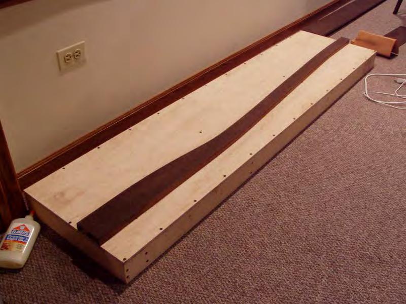
20 And so we began collecting like-minded modelers and building midwestern prototype scenes mostly Milwaukee Road.

21 Keith Kohlmann came next with Berryville, WI on the C&NW, then Oklahoma Ave on the Milwaukee, Sturetevant and Hwy 20 in Wisconsin, and now the C&NW Lakefront Depot
 and built Franksville, Tower A68, and")
22 Jamie VonDruska introduced us to static grass (peer pressure ) and built Franksville, Tower A68, and Caledonia.

23 Nate Pierce built two modules featuring the Wisconsin Dells
, and some sweet display boards by our Iowa division, pretty soon we have too much")
24 40 x60 NMRA 2010 And after Matt Gaudynski (Springdale Rd), Rick Hall (Techny), Matt Jacobs (Oakwood), and some sweet display boards by our Iowa division, pretty soon we have too much stuff
25 Modular Layout Video
26 Modular Layout Construction Practices


27 Sippin and Switchin Style Test Module
28 Standard Straight Module (18 x 60 )

29 Module Build Sequence Video

30 Spline Roadbed Construction

31 Spline Roadbed Construction

32 Spline Roadbed Construction

33 Spline Roadbed Construction

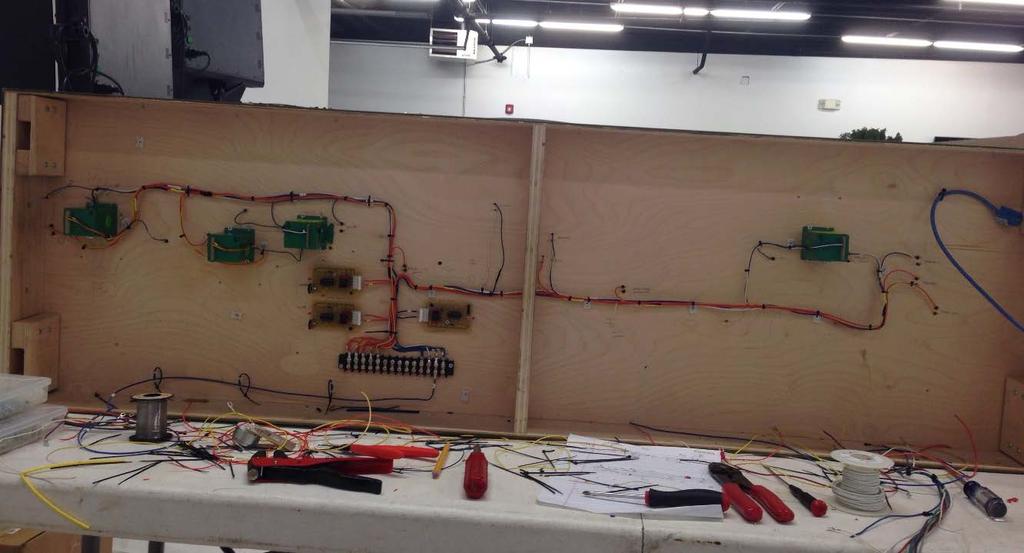
34 Spline Roadbed Construction

35 Spline Roadbed Construction

36 Spline Roadbed Construction

37 The legs are designed to save space during transport and allow height adjustment without crawling on the floor. They use readily available materials and do not require fancy cuts or tools for construction. ~40 leg assemblies can be transported in a rolling garbage can. With the legs spanning a module joint, that s 20 modules worth of legs! Leg Construction
38 This drawing shows the overall dimensions. The two uprights are 1 x2 (nominal) Poplar cut to 24 long. The plates, one plain and one with a 6 slot, are cut from 1/8 Baltic Birch Plywood. The main leg is 2 x2 (nominal) Poplar cut to 34 long. Poplar is available in most big box home improvement stores and lumber yards. It is straight and high quality. Leg Construction

39 A t-nut is sunk into the 2x2. This nut then accepts a plastic knob with threaded insert and fender washer. Loosening the knob allows the 2x2 to slide up and down, ready to be locked in a the proper height when the layout is leveled. All this can be done without crawling on the floor, as is necessary with leveling glide feet. Leg Construction
40 Modular Layout Wiring Concepts
41 What does our ideal layout look like? - DCC - Modular Wiring - Easy Set-up - No dangling wires - Signals! (ABS)

42 Simple Corner Module Wiring

43 More Complex Depot Module


44 14 AWG 14 AWG AWG Main 1 Non-Detected Main 1 Common Main 1 Detected 4 14 AWG 5 14 AWG 6 18 AWG Main 2 Non-Detected Main 2 Common Main 2 Detected 7 18 AWG 8 18 AWG 9 18 AWG Future Future Future 18 AWG 18 AWG AWG +12 Volt +5 Volt Ground Molex Pin Connector

45 Keep the wiring tight under the modules so there is nothing to snag during transport. For connections between modules, don t leave the wires long at the ends. Simply put a female Molex connector at the modules ends and build jumpers with two male ends to plug in during set-up. These jumpers should be 12 inches long. Wiring Jumpers

46 How not to do it
 - (http://www.")


47 Panduit Cable Tie Mounts (#6 Screw) - ( 4 Nylon Cable Ties Cinch Terminal Blocks Crimp on Ring Terminals 16 AWG Stranded Wire 18 AWG Stranded Wire 24 AWG Stranded Wire Wiring Supplies

48

49
50
51 Front (Public) Side CAT 5 Cable Tortoise Module Wiring Terminal Block MAIN BUS WIRING Back (Operator) Side Standard Straight Module Wiring (from below)
52 Main 1 Common Main 1 Detected Detector Detector Detector Main 1 Non-Detected Bus DCC Main Line 1 (Detected and Non-Detected Bus Wires)
53 Main 2 Common Main 2 Detected Detector Detector Detector Main 2 Non-Detected Bus DCC Main Line 2 (Detected and Non-Detected Bus Wires)
 MAIN BUS WIRING Siding Wiring")
54 Main Line 1 Detected (Blue/White) Main Line 2 Detected (Orange/Yellow) MAIN BUS WIRING Siding Wiring (Non-Detected)
55 Tortoise Switch Machine Turnout Control
56 Tortoise Switch Machine 2.2K ohm Resistors (red-red-red) +12 Volt (Red) Add a 2.2k Ohm (red-red-red) Resistor to pins 1 and 8 and feed each with +12 Volt from the Red Bus. Turnout Control
57 Ground (Black) Tortoise Switch Machine +12 Volt (Red) Connect a wire from each phono jack to pin 1 or 8. The Tortoise throwbar will move in the direction of the grounded pin. Standard convention uses red jack for reverse on the turnout, white for normal. Turnout Control
58 Ground (Black) Tortoise Switch Machine (Resistors not shown for clarity) Frogs are green: connect a wire from frog to one of center pins on Tortoise to power the frog. +12 Volt (Red) Frog Turnout Control
59 Ground (Black) Tortoise Switch Machine (Resistors not shown for clarity) Finally, use the corresponding contacts for the frog to feed track power. Color depends on which mainline the turnout is on. +12 Volt (Red) Frog Track Feeder 1 Track Feeder 2 Turnout Control
60 Detector Detector Detector Each block uses a Chubb DCC Optimized Detector (DCCOD). Occupancy is read through a current sensing transformer (no voltage drop) with as little as a 10k resistor across the track.
61 Train Detector Detector Detector When a train enters a block, the DCCOD will detect and ground the indication in the appropriate signals.
62 Train Detector Detector Detector In general terms, the detector will drive its block signal to red (stop) and then back feed to the previous block to drive the preceding signal to approach (yellow). A signal with no grounded pins will display clear (green). Occupancy Detectors
63 Operator Side Block Signal Public Side Standard convention is to gap the front (or public side) rail for signal blocks. The gaps allow the mainline feeders for signal blocks to be fed through an occupancy detector to drive the ABS signal logic. Signal Control
64 Green Red + 12 Volt Yellow Direction Stop +12 Volts Approach Ground Detector Track 1a +12 Volts Track 2b Ground Modutrak Signal Driver DCCOD Detector CAT 5 Cable Signal Control
65 Blue/White Bus Green Red + 12 Volt Yellow Direction Stop +12 Volts Approach Ground Detector Track 1a +12 Volts Track 2b Ground Blue/White Bus Blue Bus +12 Volt Bus Ground Bus CAT 5 Cable Signal Control
66 Blue/White Bus Green Red + 12 Volt Yellow Direction Stop +12 Volts Approach Ground Detector Track 1a +12 Volts Track 2b Ground Blue/White Bus Blue Bus +12 Volt Bus Ground Bus Approach Back Fed To Previous Block CAT 5 Cable Approach From Next Block Signal Control
67 Blue/White Bus Green Red + 12 Volt Yellow Direction Stop +12 Volts Approach Ground Detector Track 1a +12 Volts Track 2b Ground Blue/White Bus Blue Bus +12 Volt Bus Ground Bus Approach Back Fed To Previous Block CAT 5 Cable Approach From Next Block Signal Control
68 Direction input is the same as Stop, for bi-directional signals against flow of traffic or, in this case, used to drop an upper head to red when Tortoise is thrown. R-Y-G Green Red + 12 Volt Yellow Direction Stop +12 Volts Approach Ground Ground (black) Bus R-L Green Red + 12 Volt Yellow Direction Stop +12 Volts Approach Ground Undetected Siding Entrance (Lunar)

69 Block Signal Since the Reverse Loop Module draws power all the time, the reverse loop segment will require it s own detector on the output side. Also, a small section of Blue mainline will be needed on both sides of the reversing segment in order to balance voltage from the same DCC supply into and out of the reverse loop. Ground Track 1a +12 Volts Track 2b Detector DCCOD Detector Reversing Output DCC Input Tony s Train Exchange DCC Reverse Loop Module End Loop Wiring Convention

70 End Loop Wiring (Actual)
71 Better Signals through peer pressure

72 BeNscale vs Modutrak


73 Etchings (PPD Ltd.)

74 Lost Wax Brass (BestCast)

75 PCB Bases (OSH Park)

76 Signal Assembly

77 Signals in resin bases

78

79 Final Installation

80 And then we pack it all up and travel the world
81 Thank You Bill Denton Marshall Skibbe Keith Kohlmann Jamie Vondruska Matt Gaudynski Harz Sondericker Vince Kotnik Nate Pierce John McCarthy Matt Jacobs Rick Hall Jim Starman
Installation Instructions Azatrax Dual Infrared Model Train Detector MRD2 'Turnout' Edition
 Installation Instructions Azatrax Dual Infrared Model Train Detector MRD2 'Turnout' Edition What it is: The MRD2 'turnout' edition is a two-channel model train detector. It can detect model trains at two
A HEATER KIT With Diesel Engine Connection Fittings
 A-12142 HEATER KIT With Diesel Engine Connection Fittings Figure 1 (General Layout and Parts I.D.) Page 1 of 6 Read these instructions and identify all components. Please retain these instructions for
INSTALLATION INSTRUCTIONS John Deere One Series; 1023E, 1025R and 1026R Models A HEATER KIT. Figure 1 (General Layout and Parts I.D.
 A-11978 HEATER KIT Figure 1 (General Layout and Parts I.D.) Read these instructions and identify all components. Please retain these instructions for future reference and parts ordering information. Refer
THERMOSTAT RETROFIT INSTRUCTIONS
 With these instructions: You will remove the two existing thermostats from the dishmachine and will replace with a single new solid-state thermostat. TOOLS REQUIRED: Adjustable Wrench Philips Screwdriver
Run Your Trains, Not Your Track!
 Digitrax Command Control Run Your Trains, Not Your Track! BDL168 LocoNet Occupancy Detector For 16 Detection Sections and up to 8 Transponder Zones All Scales Features n Occupancy Detection for 16 detection
TM channel block occupancy detector for LocoNet
 TM-56322 8-channel block occupancy detector for LocoNet User's manual 2016 BioDigit Ltd. All rights reserved. It is forbidden to reproduce and/or publish the contents of the present document in any form
Cinema-seating-in-a-box
 Cinema-seating-in-a-box A S S E M B L Y I N S T R U C T I O N S E X C I T E Y O U R S E N S E S M E T R O P O L I T A N 2 seat straight E A S T W O O D 3 seat curved G A R R I C K 1 seat B R A N D O 4
Product Support Bulletin
 MODEL: SUBJECT: CONVENTIONAL, W/ C7 CAT ENGINE WEBASTO TSL-17 HEATER Body DATE: APRIL 13, 2004 INDEX: 6 PAGE: 1 OF 16 Before you start this procedure, perform Freightliner Service Bulletin #20-7 first.
BDL168. All Scales. LocoNet Occupancy Detector For 16 Detection Sections and up to 8 Transponder Zones
 Digitrax Command Control Run Your Trains, Not Your Track! BDL168 LocoNet Occupancy Detector For 16 Detection Sections and up to 8 Transponder Zones All Scales Features Occupancy Detection for 16 detection
Multi line separator module
 Sinteso Cerberus PRO Multi line separator module FDCL221-M Multi line separator module, addressed (FDnet/C-NET) Automatic module with several separate line separators Formation of stub lines (T-branches)
SEA FROST BD 12 OR 24-VOLT D.C. AIR-COOLED SYSTEM
 148 OLD CONCORD TURNPIKE BARRINGTON, NH 03825 USA TEL (603) 868-5720 FAX (603) 868-1040 1-800-435-6708 E-Mail:sales@seafrost.com www.seafrost.com SEA FROST BD 12 OR 24-VOLT D.C. AIR-COOLED SYSTEM CONDENSING
Crimping Tools for Non - Insulated Terminals
 Crimping Tools for Non - Insulated Terminals T-100 T-112 T-122 H-100N H-104 NH-12 NH-21 8 Crimping Tools for Non - Insulated Terminals T-100 Ratchet hand tool for crimping small (0.4mm 2 ) terminals. The
Installation and Operation Manual Low Power (LP) DC Power System
 DC Power System") Installation and Operation Manual Low Power (LP) DC Power System LPS Power Enclosure LPB Battery Enclosure 2051259 R3 Information in this document is subject to change without notice and does not represent
Installation and Operation Manual Low Power (LP) DC Power System LPS Power Enclosure LPB Battery Enclosure 2051259 R3 Information in this document is subject to change without notice and does not represent
MAINTENANCE MANUAL TAIYO SEIKI CO., LTD.
 MAINTENANCE MANUAL TAIYO SEIKI CO., LTD. Introduction This Maintenance Manual explains how to replace and adjust the major components of the Automatic Taping Machine when required in daily operation.
KIT NOTICE. These instructions are for replacing the two existing thermostats with a single new solid-state thermostat.
 KIT 06401-004-22-16 5 1 2 NOTICE 3 (3 PLC'S) These instructions are for replacing the two existing thermostats with a single new solid-state thermostat. 4 PREPARATION PARTS INCLUDED 6 1 7 5 8 2 4 (4 PLC'S)
COMMON WORK RESULTS FOR ELECTRICAL: Basic Electrical Materials Methods
 1. BASIC ELECTRICAL MATERIALS 1. All conduit and raceway must be 3/4" or larger. Exposed raceway in finished areas shall be in 700 or larger wiremold. Exception: runs to individual devices 10 or less,
Operating Instructions
 D-TEK PCB-1 Vehicle Loop Detector Operating Instructions This product is an accessory or part of a system. Always read and follow the manufacturer s instructions for the equipment you are connecting this
General System Layout Sketch
 General System Layout Sketch SW-38 Solar Panel(s) Hot Water Cold Water PV panel Glycol RV Water Heater WITH built in Heat Exchanger Water Ports ` Glycol Fill Valve 1 Pump Solar Powered Expansion Tank Glycol
COMPONENT SOLUTIONS for the lighting industry
 COMPONENT SOLUTIONS for the lighting industry optimascomponents.com QUALITY, COMPONENTS & SERVICE OPTIMAS COMPONENTS CHINA, DESIGN & SOURCING Component Solutions for the Lighting Industry Optimas Components
TrainBoss Defect Detector Displaying Detector Model No. TB-21D
 TrainBoss Defect Detector Displaying Detector Model No. TB-21D Hotbox & Equipment Defect Detector for model railroads Displays 6 types of defect alarms for passing trains: hotbox, dragging equipment, high
DRAIN WATER TEMPERING INSTALL
 208/230 V DRAIN WATER TEMPERING KIT - 06401-002-59-99 460 V DRAIN WATER TEMPERING KIT - 06401-004-56-12 WARNING WARNING This kit should be installed only by qualified service personnel to reduce the risk
1. SAFETY RULES WARNING WARNING. 8. Avoid placing objects in the path of the blades.
 1 1. SAFETY RULES 1. To reduce the risk of electric shock, insure electricity has been turned off at the circuit breaker or fuse box before beginning. 2. All wiring must be in accordance with the National
Models NFPA 1221-A, NFPA 1221-B Public Safety DAS Annunciator Panel. Revision E 61117
 Models NFPA 1221-A, NFPA 1221-B Public Safety DAS Annunciator Panel Revision E 61117 CAUTION: (Read This First) This panel has been designed to make it nearly bullet proof to mistakes made when wiring
Around the cable. Pressing and crimping.... convincing solutions
 Around the cable Pressing and crimping... convincing solutions 33 INFO HUPcompact The new HUPcompact is a handy, compact crimp tool that will be available in 4 variations: HUPcompact HC01 for insulated
For more information, please visit or call toll free at
 D-TEK LM Vehicle Loop Detector Operating Instructions This product is an accessory or part of a system. Always read and follow the manufacturer s instructions for the equipment you are connecting this
Installation Instructions. For the 18 Built-In Dishwasher and Front Color Panels
 Installation Instructions For the 18 Built-In Dishwasher and Front Color Panels Printed in USA 154232102 Before You Begin DO NOT INSTALL DISHWASHER UNTIL YOU HAVE READ ALL INSTRUCTIONS. FOR YOUR SAFETY,
REV: 000. Mercury Compact Series
 REV: 000 Mercury Compact Series Table of Contents Introduction 2 Standard Operating Guide 2 Features & Specs 2 External Layout 3-8 Internal Layout 9-12 Wiring Diagram 13 F.A.Q. 14-22 Comprehensive Parts
INSTALLATION INSTRUCTIONS
 INSTALLATION INSTRUCTIONS The SensorNet I/O Module provides attachment for up to 32 alarms and up to 16 switched devices. An RS-232 or RS-422 communications port is also provided for receiving serial alarms.
Oreck Edge - Upright Tune-Up & Service Guide 02/26/2010
 The Oreck Manufacturing Company Oreck Edge - Upright Tune-Up & Service Guide 02/26/2010 Compiled by Clark DeNoble 1 Table of Contents Electrical Page 3 Tune-Up Evaluate Page 4 Clean Page 4 Replace Page
KIT NOTICE. These instructions are for replacing the three existing thermostats with a single new solid-state thermostat.
 KIT 06401-004-22-16 5 1 2 NOTICE 3 (3 PLC'S) These instructions are for replacing the three existing thermostats with a single new solid-state thermostat. 4 PREPARATION PARTS INCLUDED 6 1 7 5 8 2 4 (4
IDP-Zone-6 Six Zone Interface Module
 INSTALLATION AND MAINTENANCE INSTRUCTIONS IDP-Zone-6 Six Zone Interface Module BEFORE INSTALLING If the modules will be installed in an existing operational system, inform the operator and local authority
42 Kevlar. Instruction Manual. Kichler Lighting 7711 East Pleasant Valley Road P.O. Box Cleveland, Ohio
 42 Kevlar Kichler Lighting 7711 East Pleasant Valley Road P.O. Box 318010 Cleveland, Ohio 44131-8010 Customer Service 866.558.5706 8:30 AM to 5:00 PM EST, Monday - Friday Instruction Manual 1 1. SAFETY
60" Tulle PatioTM. Instruction Manual. A Kichler Select ceiling fan
 60" Tulle PatioTM A Kichler Select ceiling fan cul Certified for Wet Location Kichler Lighting 7711 East Pleasant Valley Road P.O. Box 318010 Cleveland, Ohio 44131-8010 Customer Service 866.558.5706 8:30
AFMS Audible Flow Monitoring System TECHNICAL SPECIFICATION
 968 AFMS AFMS TECHNICAL SPECIFICATION 08/07 Ref B ATV-ELEKTRONIK GMBH WIENER STRASSE 228 A-4030 LINZ +43 732 301600 FAX. +43 732 301600 21 Page 2 Table of contents General Introduction...3 Overview...3
General System Layout Sketch
 General System Layout Sketch EZ-37 Solar Panels PV panel Glycol Fill Valve Expansion Tank ` 1 Introduction This document describes how to install a Heliatos GH type solar water heating system. These systems
21 TRV Blower Installation Instructions
 INSTALL THE ACCENT LIGHT BEFORE THE BLOWER (IF APPLICABLE) If installing the accent light, install it first, leaving the control cover loose for blower rheostat installation. THE BLOWER IS MUCH EASIER
MMF Six Zone Interface Module
 Installation and Maintenance Instructions I56-900-005 MMF-0-6 Six Zone Interface Module SPECIFICATIONS Normal Operating Voltage: 5- VDC Stand-By Current: ma Alarm Current: 40 ma (assumes all six LEDs solid
Installation and Operation Manual AEC9005 Series Low Voltage Warning and Auxiliary Battery Management Modules
 Bob Nuckolls 6936 Bainbridge Road Wichita, Kansas 67226-1008 Voice/Fax: 316-685-8617 E-mail: http://www.aeroelectric.com/bob.nuckolls Installation and Operation Manual AEC9005 Series Low Voltage Warning
INPUT / OUTPUT MINI MODULES
 INPUT / OUTPUT MINI MODULES APPLICATION The Addressable Control and Monitor mini modules are the latest technology for a loop powered module. Installed on the same loop with other devices such as detectors
KSSS42QDW05, KSSS42QDX05
 CABINET PARTS 42" BUILT IN REFRIGERATOR 4 97 Litho In U.S.A. (mek) 1 Part No. CABINET PARTS 1 Cabinet (Not A Serviceable Part) 3 2005004 Grommet, Tube Crossover 4 1112023 Roller, Front & Rear (4) 5 Support,
INSTALLATION AND TROUBLE SHOOTING MANUAL for all Models of Nova Kool Remote Condensing units & Cold plates.
 INSTALLATION AND TROUBLE SHOOTING MANUAL for all Models of Nova Kool Remote Condensing units & Cold plates. Thank you for choosing Nova Kool for your refrigeration needs. For over 20 years we have been
52 DorsetTM. Instruction Manual. Basic Function Wall Control System Included. A Kichler Decor ceiling fan
 Basic Function Wall Control System Included 52 DorsetTM II A Kichler Decor ceiling fan Kichler Lighting 7711 East Pleasant Valley Road P.O. Box 318010 Cleveland, Ohio 44131-8010 Customer Service 866.558.5706
October 2016 NEWSLETTER
 CHIPPEWA VALLEY RAILROAD ASSOCIATION October 2016 NEWSLETTER November Meeting - 6:45 PM - Tuesday, November 1, 2016 Chippewa Valley Museum, Eau Claire, WI Carson Park, Eau Claire, WI CARL SEARING Carl
Servo Cable Connector Crimping Guide
 Crimping Tool head showing the slots and markings The Crimping Tool showing the smaller slot (marked 24-28), the larger slot (marked 20-24) and the wire cutter Left or right-hand use: Although the crimping
Bar valve with fixed and adjustable shower heads. Installation guide. Midas Plus installation instructions Page 1
 Midas Plus Bar valve with fixed and adjustable shower heads Installation guide Midas Plus installation instructions Page 1 Midas Plus Midas Plus installation instructions Page 2 Components Literature not
COMSPHERE 48 Vdc CENTRAL OFFICE POWER UNIT
 COMSPHERE 48 Vdc CENTRAL OFFICE POWER UNIT INSTALLATION GUIDE Document No. 3000-A2-GB41-50 October 2002 COMSPHERE 48 Vdc Central Office Power Unit COMSPHERE 48 Vdc Central Office Power Unit Installation
AVENGER HT THERMOSTAT RETROFIT INSTRUCTIONS
 AVENGER HT THERMOSTAT RETROFIT INSTRUCTIONS In this installation manual: You will remove the existing mechanical thermostat from the Avenger HT dishwasher and will replace it with a new solid state thermostat.
Public Safety DAS Annunciator Panel
 Public Safety DAS Annunciator Panel 120 VAC Models: 1221-A, 1221-B, 1221-C Revision D 91117 48 VDC Models: 1221-A-48, 1221-B-48, 1221-C-48 24 VDC Models: 1221A-24, 1221-B-24, 1221-C-24 CAUTION: (Read This
Dishwasher Load-Unload Indicator. Jitendra Tailor
 Dishwasher Load-Unload Indicator Jitendra Tailor Circuit and Software Operation The key to this gadget involves timing the activity of the dishwasher users. I preset the time to empty the dishwasher at
Digital Control Module Replacement Manual
 Digital Control Module Replacement Manual Commercial Backbars Z2440 Rev. 10.28.16 REMOVAL INSTRUCTIONS - Digital Control Removal Tools needed for digital control removal. 1. Screwdriver 2. Wire Cutters
Installation & Operations Manual G Series - Control Panel Package
 Installation & Operations Manual G Series - Control Panel Package Contents Equipment Inspection Review Equipment Paperwork... 4 Bill Of Material... 4 Pick Ticket Example... 5 Equipment Check... 6 System
BARRACUDA 200ZW PORTABLE WALKING FOOT SEWING MACHINE INSTRUCTION MANUAL
 BARRACUDA 00ZW PORTABLE WALKING FOOT SEWING MACHINE INSTRUCTION MANUAL THE BARRACUDA 00ZW PORTABLE WALKING FOOT SEWING MACHINE INSTRUCTION MANUAL MATERIAL IS OWNED BY RELIABLE AND MAY NOT BE REPRODUCED
FDMM01S - FDMM02 - FDMM10- FDMM11S FDMM12 - Input / output mini modules
 Application The Addressable Control and Monitor mini modules are the latest technology for a loop powered module. Installed on the same loop with other devices such as detectors and manual call points,
Learn to Use Your. SNS EasySnow. Home Snowmaker Second Nature Snowmaking All Rights Reserved
 Learn to Use Your SNS EasySnow Home Snowmaker 2009 Second Nature Snowmaking All Rights Reserved How this snowmaking stuff actually works. 1 A given something to freeze onto OR disrupted by a stream of
Modular Drawer Cabinets Installation Instructions
 Modular Drawer Cabinets Installation Instructions IMPORTANT PRODUCT LIABILITY INFORMATION Read all instructions before proceeding with installation or drawer loading. Vital product information pertaining
Instructions: Changing Existing Downrod to Longer Downrod (sold separately)
") FOR MODEL WITH REMOTE RECEIVER INSIDE CANOPY Disassemble Canopy and Remove Downrod from Canopy 1 Remove the cotter pin and clevis pin from the downrod. canopy To remove canopy, I) loosen (but do not remove)
FOR MODEL WITH REMOTE RECEIVER INSIDE CANOPY Disassemble Canopy and Remove Downrod from Canopy 1 Remove the cotter pin and clevis pin from the downrod. canopy To remove canopy, I) loosen (but do not remove)
Table of Contents. Notes... 27
 Table of Contents Parts needed:... 2 Telestart T91 kit - VW Part No. ZDK054356.... 2 Overhead Timer - VW Part No. 7L6 919 044 S... 6 Heater Core for stationary heater - VW Part No. 7L6 819 953 F... 7 Parking
AFE400 SERVICE PARTS
 This is the parts list for the AFE00. When looking up part numbers, always check the complete model and serial numbers to be certain of ordering the correct parts. The Air Cooled model has also been manufactured
Please read and digest ALL the instructions before you commence installation.
 Installation Instructions Please read and digest ALL the instructions before you commence installation. If you are still unsure, then please call or contact us through our Support page. We recommend our
SEA FROST BD 12 OR 24 VOLT D.C. SYSTEM With Water Cooling Option
 148 OLD CONCORD TURNPIKE BARRINGTON, NH 03825 USA TEL (603) 868-5720 FAX (603) 868-1040 1-800-435-6708 E-Mail:sales@seafrost.com www.seafrost.com SEA FROST BD 12 OR 24 VOLT D.C. SYSTEM With Water Cooling
TraceTek TT1000 Modular Sensing Cable
 Installation Instructions R TraceTek TT1000 Modular Sensing Cable General Information These instructions explain the proper procedures for installing and testing TT1000 modular sensing cables, and provide
Crimping Tools. For Non-Insulated Terminals. For Pre-Insulated Terminals. For Closed End Connectors. Tool-Terminals Cross Reference.
 Crimping Tools For Non-Insulated Terminals For Pre-Insulated Terminals For Closed End Connectors Tool-Terminals Cross Reference Nippon Tanshi offers crimping tools for all of our standard products. Our
Input module, input/output module
 Sinteso / Cerberus PRO Input module, input/output module FDCI221, FDCIO221 Input module and input/output module for the automatically addressed detector line Input module FDCI221: Monitorable contact input
RC801/803/ B 16E1 Fiber-Optic Multiplexer (Rev. M) User Manual. Raisecom Technology Co., Ltd. (04/2005)
 User Manual. Raisecom Technology Co., Ltd. (04/2005)") RC801/803/805-480B 16E1 Fiber-Optic Multiplexer (Rev. M) User Manual Raisecom Technology Co., Ltd. (04/2005) 1. Cautions Please read the following notices carefully before installing and using the device,
RC801/803/805-480B 16E1 Fiber-Optic Multiplexer (Rev. M) User Manual Raisecom Technology Co., Ltd. (04/2005) 1. Cautions Please read the following notices carefully before installing and using the device,
RANGE. 2600/1950 Watts. 240/208 Volts BAKE ELEMENT /2100 Watts. 240/208 Volts. 90 degree BAKE ELEMENT Watts.
 BAKE ELEMENT RANGE BAKE ELEMENT ADMIRAL AMANA CALORIC GLENWOOD HARDWICK IMPERIAL MAGIC CHEF MAYTAG WHIRLPOOL ROPER SUNRAY WELBILT 308180 2600/1950 Watts 240/208 Volts.250 male terminal push-in connection
ValkyrieTM. Instruction Manual. Includes our new CoolTouch TM 6 Speed DC Control System Looks permanent, but goes wherever you go! U.S.
 ValkyrieTM A Kichler Décor ceiling fan Designed to coordinate with a popular Kichler Lighting collection. Includes our new CoolTouch TM 6 Speed DC Control System Looks permanent, but goes wherever you
SERVICE MANUAL FOR 6636A & 6636B SERIES TWO TON HIGH EFFICIENCY PACKAGED AIR CONDITIONERS
 SERVICE MANUAL FOR 6636A & 6636B SERIES TWO TON HIGH EFFICIENCY PACKAGED AIR CONDITIONERS TABLE OF CONTENTS 1. Warnings & Component Match-Up............................................ 2 2. Unit Specifications..........................................................
Sunburst. Instruction Manual. Includes our new Wall Control System. A Kichler Décor ceiling fan
 Includes our new Wall Control System Sunburst A Kichler Décor ceiling fan Kichler Lighting 7711 East Pleasant Valley Road P.O. Box 318010 Cleveland, Ohio 44131-8010 Customer Service 866.558.5706 8:30 AM
CZ-6A Six Zone Interface Module
 INSTALLATION AND MAINTENANCE INSTRUCTIONS CZ-6A Six Zone Interface Module 658 Kitimat Rd. Unit #6 Mississauga, Ontario L5N T5-800-SENSOR, FAX: 905-8-077 www.systemsensor.ca SPECIFICATIONS Normal Operating
Fire Safety. Installation Instructions Model SMB-2 Main Control Board OPERATION INSTALLATION
 Fire Safety Installation Instructions Model SMB- Main Control Board OPERATION The SIEMENS Model SMB- board in each MXL-IQ System controls operations and monitors input device identity, network communication,
52 StarkkTM. Instruction Manual. A Kichler Select ceiling fan
 52 StarkkTM A Kichler Select ceiling fan Kichler Lighting 7711 East Pleasant Valley Road P.O. Box 318010 Cleveland, Ohio 44131-8010 Customer Service 866.558.5706 8:30 AM to 5:00 PM EST, Monday - Friday
MEIKO Undercounter Dish and Glass Washing Machine. Spare Parts List 208V/230V 1/3-PHASE 60 HZ
 MEIKO Undercounter Dish and Glass Washing Machine Spare Parts List FV40.G 08V/0V /-PHASE 60 HZ Rev.. Updated: 0-8-04 CONTENTS. WASH PUMP PAGE. WASH SYSTEM PAGE. BOOSTER PUMP PAGE 7. SOLENOID / FILL VALVE
ChicagoTM. Instruction Manual. Includes our new CoolTouch TM Control System Looks permanent, but goes wherever you go! U.S.
 Includes our new CoolTouch TM Control System Looks permanent, but goes wherever you go! U.S. Patent Pending ChicagoTM A Kichler Decor ceiling fan Kichler Lighting 7711 East Pleasant Valley Road P.O. Box
TraceTek TT1000 Modular Sensing Cable
 LEAK DETECTION powered by Installation Instructions TraceTek TT1000 TraceTek TT1000 Modular Sensing Cable Modular Sensing Cable General Information These instructions explain the proper procedures for
Installation Instructions Azatrax HexDetex Model Train Detector with Grade Crossing Trigger MRD6X
 Installation Instructions Azatrax HexDetex Model Train Detector with Grade Crossing Trigger MRD6X What it is: The MRD6X is a six-channel model train detector. It can detect model trains at up to six different
DoctorProAudio.com. U-Build It Enclosure Guide. UB4755 UB4770 UBSUB Horizontal Format Dual 12 + Compression Driver system. DoctorProAudio.
 U-Build It Enclosure Guide UB4755 UB4770 UBSUB Horizontal Format Dual 12 + Compression Driver system Vertical Format Dual 15 + Compression Driver System Dual 18 Add-on Subwoofer System Specifications Specifications
LED. 60 StarkkTM. Instruction Manual. A Kichler Select ceiling fan
 60 StarkkTM LED A Kichler Select ceiling fan Kichler Lighting 7711 East Pleasant Valley Road P.O. Box 318010 Cleveland, Ohio 44131-8010 Customer Service 866.558.5706 8:30 AM to 5:00 PM EST, Monday - Friday
WASHER/DRYER CONTROL PANEL PARTS For Models: LTE6234DQ5, LTE6234DT5 (Designer White) (Biscuit)
 (Biscuit)") WASHER/DRYER CONTROL PANEL PARTS WASHER/DRYER LAUNDRY SYSTEM 1 Literature Parts Installation Instructions 8577199 English 3397634 Arabic Use & Care Guide 8578179 English 3405528 Arabic 8542752 Sheet, Cycle
WASHER/DRYER CONTROL PANEL PARTS WASHER/DRYER LAUNDRY SYSTEM 1 Literature Parts Installation Instructions 8577199 English 3397634 Arabic Use & Care Guide 8578179 English 3405528 Arabic 8542752 Sheet, Cycle
FDCL221-M Multi line separator module
 FDCL221-M Multi line separator module addressable (FDnet/C-NET) Sinteso TM Cerberus PRO Automatic module with several line separators Creation of T taps (stub lines) in the FDnet/C-NET Operation of the
ensure Ensure Single inlet Dual inlet - only and cold
 X08060026A NOTE The manufacturer reserves the right for any modifications on the product which might be deemed necessary or useful without informing about it in this IFU. Thank you for choosing a Hisense
Can Am Commander 1000 Radiator Relocation Installation Instructions
 Can Am Commander 1000 Radiator Relocation Installation Instructions What comes with the kit 2 CNC Machined Aluminum mounting brackets 2 pcs M6 x 1.0 x 60mm long SHCS 2 pcs M6 x 1.0 x75mm long SHCS 4 pc
C Electrical Connection Kit
 1548-4010C Electrical Connection Kit For Use With Dekoron 2700 and 2300 Family of Heating Cables Installation Instructions Kit Description The Dekoron 1548-4010C electrical connection and end seal kit
WASHER/DRYER CONTROL PANEL PARTS For Model: YWET3300SQ1 (Designer White)
") WASHER/DRYER CONTROL PANEL PARTS WASHER/DRYER LAUNDRY SYSTEM 1 Literature Parts Installation Instructions W10118289 English 8578179 English W10118304 Sheet, Cycle Feature W10117522 Wire Diagram 2 3390688
WASHER/DRYER CONTROL PANEL PARTS WASHER/DRYER LAUNDRY SYSTEM 1 Literature Parts Installation Instructions W10118289 English 8578179 English W10118304 Sheet, Cycle Feature W10117522 Wire Diagram 2 3390688
Installation Instructions
 Installation Instructions For the 18" Built-In Dishwasher Sears, Roebuck and Co. Sears Canada, Inc. Hoffman Estates, IL 60179 U.S.A. Toronto, Ontario, Canada M5B 2B8 154435201 Before You Begin DO NOT INSTALL
WASHER/DRYER CONTROL PANEL PARTS For Model: YWET3300SQ0 (Designer White)
") WASHER/DRYER CONTROL PANEL PARTS WASHER/DRYER LAUNDRY SYSTEM 1 Literature Parts Installation Instructions W10118289 English 8578179 English W10118304 Sheet, Cycle Feature W10113806 Wire Diagram 2 3390688
WASHER/DRYER CONTROL PANEL PARTS WASHER/DRYER LAUNDRY SYSTEM 1 Literature Parts Installation Instructions W10118289 English 8578179 English W10118304 Sheet, Cycle Feature W10113806 Wire Diagram 2 3390688
Concepts Serving Systems
 Concepts Serving Systems Installation Manual Please read this manual completely before attempting to install or operate this equipment! Notify carrier of damage! Inspect all components immediately. February
Telo Shower Mixing Valve TL10016CP
 Telo Shower Mixing Valve TL10016CP Installation and Maintenance Instructions In this procedure document we have endeavoured to make the information as accurate as possible. We cannot accept any responsibility
CABINET PARTS For Model: KSSS48QJX00 (Stainless Steel)
") CABINET PARTS 48" BUILT IN REFRIGERATOR 10 02 Litho In U.S.A. (mek) 1 Part No. 1 LITERATURE PARTS LIT2209249 Use & Care Guide LIT2006651 Energy Label LIT2006748 Service & Wiring Sheet LIT628370 Modular
CABINET PARTS 48" BUILT IN REFRIGERATOR 10 02 Litho In U.S.A. (mek) 1 Part No. 1 LITERATURE PARTS LIT2209249 Use & Care Guide LIT2006651 Energy Label LIT2006748 Service & Wiring Sheet LIT628370 Modular
DIRTMAG dirt separator with magnet, adjustable for vertical or horizontal pipe
 DIRTMAG dirt separator with magnet, adjustable for vertical or horizontal pipe Copyright 206 Caleffi NA0322.02 www.caleffi.com NA5453 Series Installation, commissioning and servicing instructions Function
MAKING MODERN LIVING POSSIBLE. Thermostatic expansion valves, type TR 6 REFRIGERATION & AIR CONDITIONING DIVISION.
 MAKING MODERN LIVING POSSIBLE Thermostatic expansion valves, type REFRIGERATION & AIR CONDITIONING DIVISION Technical leaflet Technical leaflet Thermostatic expansion valves, type Contents Page Introduction........................................................................................3
Deluge Shower Mixing Valve 10045CP
 Deluge Shower Mixing Valve 10045CP Installation and Maintenance Instructions In this procedure document we have endeavoured to make the information as accurate as possible. We cannot accept any responsibility
60" Hatteras BayTM. Patio. Instruction Manual. Includes our new Wall Control System. A Kichler Décor ceiling fan
 Includes our new Wall Control System 60" Hatteras BayTM Patio A Kichler Décor ceiling fan Kichler Lighting 7711 East Pleasant Valley Road P.O. Box 318010 Cleveland, Ohio 44131-8010 Customer Service 866.558.5706
Infrared Wall Mount Occupancy Sensor
 LOS-WI LOS-WI-1 02.01.06 Infrared Wall Mount Occupancy Sensor The LOS-WI wall-mounted passive infrared sensor is used in spaces with pendant fixtures, ceiling fans, or high ceilings (more than 12 feet).
CABS/BLADES/ SPREADERS/ACCESSORIES
 JOHN DEERE 3000 SERIES (4200/4300/4400) (4210/4310/4410) (3120/3320/3520/3720) JOHN DEERE 4000 SERIES (4500/4600/4700) (4510/4610/4710) (4120/4320/4520/4720) OPTIONAL AUXILIARY HEATER INSTALLATION (p/n
21-light Remote Annunciator. Owner s Manual
 21-light Remote Annunciator Owner s Manual Annunciator Description... Inside Font Cover Detailed Specifications... 1 Environmental Specifications... 1 Power Supply Requirements... 1 Communication With
SECTION COMMUNICATIONS HORIZONTAL CABLING
 SECTION 27 15 00.19 COMMUNICATIONS PART 1 - GENERAL 1.1 SUMMARY A. Section includes the following: 1. Category 6 and Category 5e horizontal UTP cabling. 2. Cable connecting hardware, patch panels, patch
Connecting and Routing the Cables
 This chapter explains how to connect and route the cables for NCS 2006. The sections are: Cable Routing and Management, on page 1 NTP-L13 Installing the Cable and Fiber Modules, on page 2 NTP-L14 Attaching
Installation guide PRO7-VAQ E. Before installing read this guide first
 Installation guide PRO7-VAQ E Before installing read this guide first Introduction The operation of the Quooker PRO7-VAQ E The Quooker system consists of a small tank under the sink which is connected
INSTALLATION INSTRUCTIONS UNDERCOUNTER DISHWASHERS
 INSTALLATION INSTRUCTIONS UNDERCOUNTER DISHWASHERS VIKING 111 Front Street Greenwood, Mississippi 38930 USA (662) 455-1200 IMPORTANT - PLEASE READ AND FOLLOW Before beginning - please read these instructions
Roto-Jet I & II Tube Cleaning Systems
 Roto-Jet I & II Tube Cleaning Systems Tube Size Tube Section Deposit Thickness of Deposit Deposit Flush 0.312 to 2.000 Straight Soft, guy, Light (7.9 to 50.8) ID Curved or organic Medium Dry Elliott Tool