Victoreen 942A-200. Operators Manual. Universal Digital Ratemeter
|
|
|
- Bartholomew Butler
- 6 years ago
- Views:
Transcription
1 Victoreen 942A-200 Universal Digital Ratemeter Operators Manual February 2005 Manual No. 942A Rev , 2005 Fluke Corporation, All rights reserved. Printed in U.S.A. All product names are trademarks of their respective companies
2 Fluke Biomedical Radiation Management Services 6045 Cochran Road Cleveland, Ohio Andrews Road Hicksville, New York
3 Table of Contents Section 1: General Information General Description Application Specifications Auxiliary Equipment Recommended Spare Parts Receiving Inspection Storage Section 2: Operation Installation Setup Operation Operator Functions Operational Modes Calibration (Scaler) Mode Operation Alarms Configuration Functions Jumper Selectable Options UDR Function Switch/Function Parameter Entry Setpoint Descriptions Setpoint Error Codes Analog Output Software Calculations Section 3: Theory of Operation Functional Description Main Circuit Board ( , Appendix A) Section 4: Maintenance, Calibration and Troubleshooting Maintenance Calibration Troubleshooting Appendix A: Connector Designations...A-1 A.1 Connector Designations... A-1 i
4 Appendix B: Applicable Drawings and Bill of Material...B-1 B.1 Applicable Drawings... B-1 B.2 Applicable Bill of Materials... B-2 Appendix C: Cable Termination Instructions...C-1 C.1 Cable Termination Instructions...C-1 ii
5 Introduction General Description 1 Section 1 Introduction 1.1 General Description The Victoreen 942A-200 Universal Digital Ratemeter (UDR), when connected to a beta or gamma sensitive scintillation detector, or a GM process probe, comprises a monitoring system which operates in the range of 10 to 10 7 counts per minute (CPM). The UDR provides display, control, and annunciator functions for the monitoring system. Standard features for the instrument consist of a five-digit display of the CPM value and a multicolored bargraph indicator that covers the entire range of the UDR. The bargraph will change color in the event of an alarm condition. Front panel alarm indicators and rear panel output relays for alarm annunciation are also included. Front panel pushbuttons are provided to display alarm limit setpoints and high voltage value, for alarm acknowledgment, and the activation of a check source function. The 942A-200 UDR provides an interface for a solenoid operated check source. The 942A-200 provides 120 VAC to the Check Source relay to actuate the check source solenoid at the J1 connector. Refer to Figure 1-1 for a general view. NOTE The Loop Drawing 942A provided in Appendix A is intended to provide generic information on the UDR. Refer to the specific project Loop Diagram provided with your UDR radiation monitoring system for specific information on the hardware provided. Analog outputs of 0 to 10 VDC and 4 to 20 ma are provided for recording and computer monitoring. The 0 to 10 VDC output may also be used to drive a remote meter. All electronics required to interface to the Victoreen 943 series radiation detectors are included within the 942A-200 UDR. These electronics consist of a high voltage power supply, low voltage detector power supply, and detector input signal conditioning. The system also includes a detector shutdown feature on overrange to prevent damage to the detector and to preclude the possibility of on-scale readings in very high radiation fields due to radiation effects on the electronics. The following paragraphs describe the available options. A separate manual, for each option, is available with more detailed information. Listed below are the option boards currently available. Refer to Section 1.3 for currently available modifications and to Appendix C for the Bill of Materials : ANALOG OPTION INPUT BOARD - Contains four separate channels for analog input. A 0 to 10 VDC input or 4 to 20 ma input can be selected independently for each channel using the jumpers and switches provided on the board. Possible inputs to the board include: temperature, pressure, flow, or simulated radiation : COMMUNICATIONS LOOP OPTION BOARD - Designed to enable a EIA RS-232C standard communications link between Victoreen s ratemeter and a user computer system or CRT terminal, with baud rates ranging from 50 baud to baud. An asynchronous communication interface adapter is utilized to format the data and control the interface. 1-1
6 Victoreen 942A-200 Operators Manual The Victoreen communications interface also provides the necessary circuitry to allow interconnecting to a standard Victoreen communication link. This interface allows multiple UDRs to share a common six-wire cable to a main central processor unit : SINGLE CHANNEL ANALYZER (Americium REGULATOR) - Designed to provide two independently adjustable windows for the discrimination of radiation pulses using the voltage peak analysis technique. Used with an Americium configured system. (When used with an Americium doped sodium iodine crystal, provides the ability to automatically adjust the detector high voltage to compensate for photomultiplier tube gain changes due to ambient temperature variations.) : ANALOG OUTPUT BOARD - Designed to provide a user selectable single output voltage of: 0-10 VDC, 0-5 VDC, 0-1 VDC, mv DC, mv DC, 0-50 mv DV, or 0-10mVDC M1: DUAL ANALOG OUTPUT BOARD - Designed to provide two user selectable output voltages. Output #1 is either 0-5 VDC, or 0-10 VDC, while output #2 is either 0-10 mv DC, 0-50 mv DC, mv DC, mv DC, or 0-1 VDC. 6. S157033A2: Line Filter/Surge Suppressor Assembly - Designed to provide EMI/RFI protection for the 942A series digital ratemeter and 943 series scintillation detectors. The assembly consists of two (2) separate and independent line conditioning circuits that provide filtered AC power to each 942A series ratemeter. The S157033A2 is designed to mount in the center section of the 948B-1A- 5 rack Chassis, to provide EMI/RFI protection for two (2) 942A series digital ratemeters. The major active components of the S157033A2 are two (2), 960SS-200 Surge suppressor circuit boards, two (2), A Line Filters, and two (2) ferrite cubes. The S157033A2 also contains AC line and neutral fuses to protect the internal circuitry from over voltage conditions. 1.2 Application The 942A-200 UDR can be used with all Victoreen 943 series beta scintillation detectors, 943 series gamma scintillation detectors, and series GM process probes. The detector, when connected to the UDR, will comprise a single channel digital process monitoring system. Table 1-1 is a list of compatible 943 series detectors. The UDR may also be used with older style Victoreen detectors. Please contact Fluke Biomedical, Radiation Management Service at for additional information. Table Series Detectors Compatible with 942A-200 UDR Detector Type Crystal End Window/Crystal Configuration (dia/size) Alpha Detector Zn S Aluminized Mylar/2 in Beta Detector Hi-Temp Plastic Aluminized Mylar/2 in T Beta Detector Hi-Temp Plastic Titanium/2 in TA Beta Detector Hi-Temp Plastic 10:1 Attenuation Titanium/2 in TB Beta Detector Hi-Temp Plastic 100:1 Attenuation Titanium/2 in * Beta Detector Hi-Temp Plastic Aluminized Mylar/2 in T* Beta Detector Hi-Temp Plastic Titanium/2 in Gamma Detector NaI (TI) Stainless Steel/1.5 x 1 in Gamma Detector NaI (TI) Aluminum/1.5 x 1 in CS Gamma Detector W/integral Check Source NaI (TI) Stainless Steel/1.5 x 1 in 1-2
7 943-36H Gamma Detector (High Temp) NaI (TI) Aluminum/2 in Gamma Detector NaI (TI) Stainless Steel/2 x 2 in A Gamma Detector NaI with Americium Stainless Steel/2 x 2 in Detector Housing is stainless steel unless otherwise noted: * Carbon Steel Housing Introduction Application Specifications General specifications for the 942A-200 UDR are listed below. The is rated for nuclear applications, and any repairs to it by personnel not qualified to ANSI , Skill Level II will void the nuclear rating. If a problem develops, the UDR can either be returned to the factory for service, or repaired by a qualified technician. General Specifications for the 942A-200 UDR Main Display Bargraph Display Alarm Indicators Display Selection Check Source Alarm Ack. Power ON/OFF Relay Outputs High Voltage Detector Power Seven Segment Three digits with backlighted units display and floating decimal points. Five-digit exponential setpoint entry Three segments per decade, 10 to 10 7 CPM (24 segments total, green to normal; amber for WARN and RED for high) HIGH Alarm (Red LED) Flashing until acknowledged WARN Alarm (Amber LED) Flashing until acknowledged RATE Alarm (Red LED) Flashing until acknowledged (optional) FAIL Alarm (Red LED) Does not flash, is not manually acknowledged RANGE Alarm (Red LED) overrange/underrange Does not flash HV, High Voltage value HIGH, High Alarm limit WARN, Warn Alarm limit RATE, Rate-of-Rise limit (OPTIONAL) Activates with associated green LED indicator Alarm acknowledgement, resets alarm relay outputs and causes alarm indicators to go to a steady on state after acknowledgement. Internal jumper causes alarms to be reset automatically when system returns to normal operation (no operator input required). Alternate action pushbutton HIGH Alarm 2 sets. SPDT rated VAC (one set 120 VAC powered for use with optional local alarm) WARN Alarm 2 sets. SPDT rated VAC RATE Alarm 2 sets. SPDT rated VAC FAIL Alarm 2sets. SPDT rated VAC Variable from 450 to ma ± ma 1-3
8 Victoreen 942A-200 Operators Manual Recorder/Computer Outputs Two 4 to 20 ma (500 Ω load max. each), and one 0 to 10 VDC (1 KΩ load min.), logarithmic scaled to the ratemeter range (from 1 to 6 decades) Remote Alarm Ack Input Detector Input Statistical Accuracy Optically isolated DC input Digital pulse train. Detector may be located up to 1500 feet from the ratemeter. Individually adjusted upper and lower level discriminators limit MeV response to desired range. 50 ohm input impedance. Statistical accuracy is user selectable at 2%, 5%, 10%, or fixed at a one second update. Count time automatically adjusts per selected accuracy and count rate. UDR Electronic Accuracy response ± 1% of the displayed value (± 1 digit), exclusive of detector energy Rate-of-rise Alarm (Optional) Provides an alarm (Red LED), momentary display select, and relay output when rate-of-rise exceeds the rate-of-rise set point. Dimensions (H x W x D) Weight 3.5 x 5.6 x 13.5 in (8.9 x 14.2 x 34.3 cm) Approximately 3.7 lbs (1.67 kg) Power 120/240 VAC ± 10%, 50/60 Hz, 28 watts (240 VAC optional) Operating Temperature 32 F to 122 F 0 C to + 50 C Relative Humidity Compatible Detectors 0 to 99% non-condensing 943-XX Series Scintillation Detectors X Series GM Detectors 1-4


9 Introduction Specifications 1 Figure A-200 Universal Digital Ratemeter, Front Panel Figure 1-1A. 942A-200 Universal Digital Ratemeter, Rear Panel 1-5
10 Victoreen 942A Operators Manual 1.4 Auxiliary Equipment Model Number Description 942-TS UDR Test Set 948A-50-5 Local Alarm/Meter Rack Chassis (Three Bay) 948-1A Rack Chassis (Two Bay, 5.8 in. Wide) 948B-1-5 Rack Chassis (Two Bay, Standard Width) 948B-1A-5 Rack Chassis (Two Bay, Standard Width, with Surge Suppressor mounting) 948A-2 Blank Panel Table Top Enclosure Panel Adapter S157033A2 Line Filter/Surge Suppressor 1-6
11 Introduction Auxiliary Equipment 1 Table A-200 Modifications Modification 942A-200-M1 942A-200-M2 942A-200-M3 942A-200-M4 942A-200-M5 942A-200-M6 942A-200-M7 942A-200-M8 942A-200-M9 942A-200-M10 942A-200-M11 942A-200-M12 942A-200-M13 Description/Modification Relocated DIGIT, VALUE, & ENTER switches, remove power switch, add 5 VDC LED to front panel. Modified to operate with /30 series detectors. Modified to operate with /30 series detectors, Two High Alarm setpoints. Modified to operate with /30 series detectors, ; Single Channel Analyzer (AM Regulator) installed ; 4-Channel Analog Input Option, ; RS-232 Communication Option, UDR to adjust the radiation readings by compensating for pressure changes at the skid, Check Source relay to remain energized for three minutes, software for historical file transfer, display in μci/cc, and key lock for data entry ; Single Channel Analyzer (AM Regulator) ; 4-Channel Analog Input Option M1; Dual Analog Output Option; (0-5 VDC and 0-10 mvdc) , RS-232 Communication Option. Readout in mrem/hr ; 4-Channel Analog Input Option, ; RS-232 Communication Option, ; Single Channel Analyzer (AM Regulator) ; RS-232 Communication Option (TWO), ; 4-Channel Analog Input Option , RS-232 Communication Option & μci/cc readout. 942A-200-M14 Modified to operate with 843-2/3 series detectors. 942A-200-M M1; Dual Analog Output Option; (0-5 VCD and 0-10 mvdc), & ; 4-Channel Analog Input Option, UDR to adjust the radiation readings by compensating for pressure changes at the skid ; RS-232 Communication Option, ; 4-Channel Analog Input 942A-200-M16 Option. 942A-200-M ; RS-232 Communication Option, ; 4-Channel Analog Input Option, M1; Dual Analog Output Option. 942A-200-M ; RS-232 Communication Option (TWO), ; 4-Channel Analog Input Option, μci/cc readout, software for historical file transfer and print to Gulton Microprint 20 printer, utilize the rate-of rise relay as a second alarm relay, all boards sprayed with conformal coating, and key lock for data entry ; RS-232 Communication Option, M1; Dual Analog Output 942A-200-M19 Option. 942A-200-M19A ; RS-232 Communication Option, M1; Dual Analog Output Option, 5 second extended mute after CS operation. 942A-200-M20 942A-100 back panel, ; RS-232 Communication Option. 942A-200-M21 942A-200-M22 942A-200-M23 942A-200-M24 942A-200-M25 942A-200-M26 942A-200-M27 Readout in mrem/hr and interface for SCAN RAD software. Standard UDR with a front panel signal input BNC connector, utilized for test purposes. Standard UDR to provide S95251A outputs ; 4-Channel Analog Input Option, ; RS-232 Communication Option, ; Single Channel Analyzer (AM Regulator). Operator selectable slope setpoint and percent efficiency setpoint, CPM/CF readout. Reserved. Standard UDR modified to use a Liquid Scintillation Detector and LSD-100 Line Driver ; Single Channel Analyzer, μci/cc readout. 1-7
12 Victoreen 942A-200 Operators Manual 942A-200-M , RS-232 Communication Option, ScanRad communication capability. Modification Description/Modification 942A-200-M , RS-232 Communication Option, ScanRad communication capability, firmware for interface with a neutron detector. 942A-200-M30 Revised rear panel wiring to match (S15173A2). 942A-200-M31 Special, 8.45 in wide front panel to mount Digit, Value, Enter, and Function Switch and Recorder Output PC board. 942A-200-M32 Special, 8.45 in wide front panel to mount Digit, Value, Enter, and Function Switch, Recorder Output PC board, and SCA board. 942A-200-M ; SCA board, RS-232 board and μci/cc display. 942A-200-M , RS-232 board and Historical Data Storage. 942A-200-M ; SCA and SF8013A210 Backlight Insert, Counts/sec. 942A-200-M M1; Analog Output board and 120-ohm signal input resistor for detector. 942A-200-M37 Front panel BNC Signal Input Jack and DPDT Switch, RATE Push button functions as TRIP TEST switch, 0-10mV analog output, RANGE alarm to trip when CPM drops below 9 CPM, and FAIL alarm to trip 10 seconds after RANGE alarm. 942A-200-M38 Front panel BNC Signal Input Jack and DPDT Switch, RATE Push button functions as TRIP TEST switch, 0-10mV analog output. 942A-200-M , RS-232 and SCA boards. 942A-200-M ; RS-232 board, SCA board, μci/cc display insert, and RATE relay to follow ALARM relay operation. 942A-200-M , RS-232 board and ScanRad firmware. 942A-200-M , RS-232 board, Analog Input board and ScanRad firmware. 942A-200-M , RS-232 board, Analog Input board, and SCA board. 942A-200-M D; μci/ml display and remove impedance matching resistor R54, to permit use of a second UDR as a remote display. 942A-200-M45 Adds A; Gain adjust pot, D μci/ml display, and functions as a remote display for 942A-200-M A-200-M46 Firmware change; Change UNDERRANGE limit from 10 to 1 CPM and FAIL time from 5 to 30 minutes. 942A-200-M ; Analog Input board. 942A-200L ; SCA, M1 Analog Output board, L-20 Front Panel, with RATE button changed to TEST, TEST firmware, and LED Check Source wiring modification. 942A-200L-M ; RS-232 board, M1 Analog Output board, L-20 Front Panel, with RATE button changed to TEST, TEST firmware, RS-232 Line Driver, and LED Check Source wiring modification. 942A-200L-M ; RS-232 board, SCA board, L-20 Front Panel, with RATE button changed to TEST, TEST firmware, RS-232 Line Driver, and LED Check Source wiring modification. 942A-200L-M , RS-232 board, Auxiliary Check Source output wiring modification, and LED Check Source wiring modification. NOTE Consult Fluke Biomedical for specific details about each option. 1-8
13 Introduction Auxiliary Equipment A - 200X - YZZ 942 = Universal Digital Ratemeter for Process Monitoring Applications A = Rear Panel Options A B = Rear Panel Connectors = Rear Panel Terminal Blocks with retractable ribbon cable 200X = Model Series 2 = High Reliability Electronic Components 00 = Reserved for Future Use X = Series Variation (Used for Factory Standard Series Variations only) L = 15 VDC output for Check Source YZZ = Modification Suffix (Used for Factory Modification Options only) Y = Modification Type Identifier M = Process Monitor Application S = Simulator Application ZZ = Sequential number, 1 through N Figure A-200 UDR Ordering/Part Number Matrix. 1.5 Recommended Spare Parts Table 1-5. Recommended Spare Parts List for the 942A-200 Universal Digital Ratemeter Part Number Description Used On Front Panel Assembly Ribbon Cable, 18C, Front Panel (5 Required) A Fuse F2, 1 AMP A Jumper Block (10 required) P Receptacle, P1, I/O, 37 Pin S Receptacle, P2, Detector, 14 Pin P Receptacle, P3, Power, 4 Pin A MHV Bulkhead Receptacle, P4, HV A BNC Bulkhead Receptacle, P5, Signal Receptacle, P6, Aux, 24 Pin Receptacle, P7, RS A Mating Connector Kit Power Supply Relay PC Board Assembly Relay H.V. PC Board Assembly - 1-9
14 Victoreen 942A-100 Operators Manual 1.6 Receiving Inspection Upon receipt of the unit: 1. Inspect the carton(s) and contents for damage. If damage is evident, file a claim with the carrier and notify Fluke Biomedical at Remove the contents from the packing material. 3. Verify that all items listed on the packing list have been received and are in good condition. 1.7 Storage NOTE If any of the listed items are missing or damaged, notify Fluke Biomedical. Storage of Victoreen instruments must comply with Level B storage requirements as outlined in ANSI N (1972) Section 6.1.2(.2). The storage area shall comply with ANSI N (1972) Section 6.2 Storage Area, Paragraphs through Housekeeping shall conform to ANSI N (1972). Level B components shall be stored within a fire resistant, tear resistant, weather tight enclosure, in a well-ventilated building or equivalent. Storage of Victoreen instruments must comply with the following: 1. Inspection and examination of items in storage must be in accordance with ANSI N (1972) Section Requirements for proper storage must be documented and written procedures or instructions must be established. 3. In the event of fire, post-fire evaluation must be in accordance with ANSI N (1972), Section Removal of items from storage must be in accordance with ANSI N (1972), Sections 6.5 and
15 Operation Installation 2 Section 2 Operation 2.1 Installation Installation consists of mounting the equipment, making the required electrical connections, and entering the desired set points. CAUTION UDR. Remove all power prior to installing the UDR Mounting The UDR is a self-contained unit that can be mounted in four different ways. CAUTION When Installing the UDR in enclosed panels or cabinets, ensure that the maximum operating temperature (122 F) is not exceeded. The total heat load should be calculated to determine whether cooling by natural convection or forced ventilation (i.e. fans) is required. The heat load for a single UDR Is approximately 96 BTU/hr. NOTE Where more than four units are to be mounted in a cabinet, it is recommended that the center position in each chassis be left blank to facilitate the flow of cooling air through the cabinet. NOTE For seismic applications, the rear of the chassis must be supported, or the sides of the chassis must be fastened together. For further Information, contact Fluke Biomedical. 1. The first mounting utilizes a 19-inch rack chassis adapter, Victoreen This configuration requires 3.5 inches of rack height and can be used to mount up to three UDRs side by side. A blank filler panel, Victoreen 948-2, is available to cover unused mounting positions. Refer to drawing GEL for mounting dimensions. 2. The second mounting consists of a single channel tabletop enclosure, Victoreen Dimensions for the enclosure are 4.5 inches high by 6.8 inches wide by 14.9 inches deep. Refer to drawing for mounting dimensions. 2-1
16 Victoreen 942A-100 Operators Manual 3. The third mounting consists of a panel mount enclosure, Victoreen Cutout dimensions for this enclosure are 3.75 inches high by 6.45 inches wide; the outside dimensions for the enclosure are 4.0 inches high by 6.7 inches wide by 13.7 inches deep. Refer to drawing for mounting dimensions. 4. The fourth mounting utilizes the Victoreen Rack Chassis Adapter to mount a 956A- 200 UDR into an existing Victoreen analog ratemeter rack chassis. Refer to drawing GEL for mounting dimensions. The UDR is simply inserted into the selected mounting enclosure and secured using the front panel pawl fastener. Electrical Interface WARNING Ensure all power is off prior to connecting the field wiring Electrical interconnections are performed using the mating connector kit, Victoreen part number 942A , and by using the connector input/output assignments provided in Appendix A, and the loop drawing 942A provided in Appendix B. Termination instructions for coaxial connections can be found in Appendix C. Connector pins should be soldered to customer furnished cable, using 60/40 tin/lead resin core solder. 2.2 Setup To place the system in operation, the following steps should be performed: NOTE Ensure you have read and fully understand Section 3 prior to continuing. 1. Verify that jumpers and DIP switches on the UDR, are set for the operational features desired. Refer to Section 2, Table Apply power to the unit. The bargraph will illuminate momentarily followed with a momentary actuation of the digital value display. The unit will then begin to display the ambient radiation at the detector location. NOTE Calibration constant and detector deadtime value are obtained from the factory calibration data sheet for each particular detector. 3. Detector dependent set points such as analog outputs, Range, Overrange limit, calibration constant, detector deadtime value, and channel dependent setpoints such as alarm limits may now be verified and if required, modified using the procedures outlined in Section Electronic adjustments affecting calibration are factory set and should not be readjusted for initial operation unless the UDR has been in storage for more than one year. If the Unit has been in storage for more than one year, the electronic calibration described in Section 4 should be performed. 2-2
17 Operation Operation Operation Operation of the 942A-200 UDR consists of operator functions and configuration functions. All operator functions are performed using the front panel shown in Figure 1-1. Configuration functions are performed using internal switches and/or jumpers, which are accessible with a partial removal of the UDR from the mounting enclosure. Calibrations involving trim pots are described in Section Operator Functions Normal Operation If the measured radiation field is within the range of the detector during power-up, the CPM value will be displayed as a three digit number: M.MMEN, where M = 0 to 9 with a single digit exponent N, where N = 0 to 9 and can be either positive or negative. For example, 2.97 x 10 4 would be displayed as 2.97E4. The bargraph will display the value on the fixed CPM scale and any indicator lights which are on (ON/OFF, CHECK SOURCE) should be green, providing the operator with a visual indication of normal operation. WARN/HIGH/RATE Alarms NOTE The RATE alarm is implemented as an option at the time of purchase. If the measured radiation field increases above the WARN alarm limit, the WARN alarm indicator will turn on flashing (amber color), the bargraph will change color to amber, and the WARN alarm relay will deactivate. If the measured radiation field increases above the HIGH or RATE alarm limit, the HIGH or RATE alarm indicator will turn on flashing (red color), the bargraph will change color to red, and the high or rate alarm relay will de-activate. NOTE Normal WARN, HIGH and RATE alarm relay operation is fail safe, if the relay is normally energized, and de-energized when the alarm condition is active. Non-failsafe relay operation for the HIGH, WARN, and RATE alarms is available as an option at time of purchase. The UDR can be configured to automatically reset the alarm relays and alarm indicators, or it can hold the alarm relays energized and flash the alarm indicators until the alarm acknowledge (ALARM ACK) pushbutton is pressed. If the ALARM ACK pushbutton is pressed while the alarm condition still exists, the indicators will go to a steady state, and the relays will remain energized until the alarm condition returns to normal. Upon resumption of normal operation, the relays and alarm indicators will de-energize. The bargraph color will always indicate the current status; green for normal, amber for warn, and red for a high alarm. Front panel pushbuttons labeled HIGH, WARN, and RATE can be used to display the respective alarm set points. Range Alarm If the measured radiation field is below a minimum range of 1.00E1 CPM, the front panel display will indicate 0.00E0 CPM, the bargraph will extinguish and the RANGE alarm indicator will illuminate in red, 2-3
18 Victoreen 942A-100 Operators Manual (the minimum range is adjustable and is defaulted to 10 CPM). When the measured radiation field increases into the range of the detector, the RANGE alarm indicator will extinguish and normal operation will begin. If the measured radiation field goes above the overrange set point, the RANGE alarm indicator will illuminate and the front panel display will indicate EEEEE. The maximum range of the detector used is determined by the overrange set point. When the measured radiation field returns within the maximum operating range of the detector and the condition is acknowledged, the RANGE alarm indicator will extinguish and normal operation will resume. In the event the detector output exceeds the electronic antijam circuit trip level, the anti-jam fuse will open and the fail relay will change state to indicate a monitor not in service condition. Replacement of the fuse will be required in order to return the ratemeter to normal operation. Fail Alarm There are several equipment failure conditions that can produce a FAIL alarm and in some cases an error display. The fail condition is true whenever any equipment failure is detected and false when no equipment failures are detected. When a fail condition occurs, other than power failure, the red FAIL alarm indicator illuminates and the fail relay coil de-energizes. To return the channel to normal operation after a FAIL alarm, the condition, which caused the alarm, must be located and corrected. Check Source The check source pushbutton and electronics are provided to verify detector operation. To operate the check source, press the CHECK SOURCE pushbutton and hold it down. The Check Source LED will illuminate, and the radiation value will increase. Releasing the check source pushbutton will allow normal UDR operation. An internal configuration jumper allows alarms to be activated air deactivated in the check source mode. The analog outputs are forced to their low scale value during a check source operation. Firmware Version This system requires a PROM for UDR operation. For the part number and the latest revision of the PROM, see the UDR Factory Test Data Sheet. 2.5 Operational Modes Normal Operation, Rate The UDR is in normal operation when the UDR function switch (see "Parameter Entry" Section 2.11) is in any position except 8, and the Check Source button is OFF. During normal operation, the display shows the dose rate data received from the detector in counts per minute (CPM). The bargraph will also show the present CPM value. The color of the illuminated segments is green when the CPM rate is below the WARN setpoint, amber when the CPM rate is above the WARN setpoint and below the HIGH setpoint, and red when the CPM rate is above the HIGH setpoint. The analog outputs are active while the UDR is in RATE MODE, and all alarms are enabled. Alarm Inhibit Alarms are inhibited in situations where an alarm trip would be meaningless because the UDR is not in a normal measurement mode (i.e., when the UDR is in the Check Source, Calibrate, or Data Entry Mode). During Alarm Inhibit, new alarm trips cannot occur and old alarms cannot be reset. When the inhibit period is over, alarm trips and resets are enabled again. Alarm inhibit conditions are discussed in the following paragraphs. 2-4
19 Operation Operational Modes 2 Data Entry Mode Data Entry Mode is selected by pressing the ENTER pushbutton while the rotary FUNCTION switch is in a valid setpoint position (see "Parameter Entry" Section 2.11). The selected setpoint is displayed in exponential format (e.g. 1.00E2) with the left most digit flashing. If the FUNCTION switch is not in a setpoint position, pressing the ENTER button has no effect. Refer to Table 2-2 for FUNCTION switch positions. In the Data Entry Mode, all alarms are inhibited. The bargraph and analog outputs hold at their previous values. The check source and alarm acknowledge functions are inoperative. Check Source Mode The check source pushbutton and electronics are provided to verify detector operation. To operate the check source, press the CHECK SOURCE pushbutton and hold it down. The 110 VAC check source relay will energize, the check source indicator will illuminate (green), and the check source solenoid will expose the source by removing it from the source capsule shielding. The radiation value will be displayed on the front panel. Releasing the check source pushbutton will return the source capsule to its shielded position and extinguish the check source indicator, allowing normal UDR operation. After approximately 10 seconds, the displayed value will begin to indicate ambient radiation. An internal configuration jumper allows alarms to be activated or muted if alarm limits are exceeded by the check source radiation value. The bargraph operates the same way as it does during normal operation. The analog outputs are at low scale during Check Source operation. 2.6 Calibration (Scaler) Mode Operation Calibrate mode for the UDR is entered by turning the rotary set point switch to position 8 and pressing the ENTER button. The current calibration time set point is displayed in seconds, with the first digit flashing to indicate the edit mode. The bargraph will turn off, high and warn conditions will clear, and the radiation unit light (backlights) will turn off. The calibration set point may be edited, but will reset to 60 seconds whenever the unit is turned off or the functional switch is moved from position 8. Once the desired calibration time is set, pressing the ENTER button will start the calibration. The display will go to zero, the backlights will begin to flash, and the Norm, Warn, and Fail relays will change state. The UDR will count for the entered calibration time, displaying the current summation of counts per second. When the calibration is completed, the final summation of counts for the calibration time is displayed and the backlights will be steady on. Another calibration can then be executed by pressing the ENTER key, and the system will again display the calibration time for editing. A calibration in process can be stopped by pressing the ENTER key. Calibrate mode can be aborted at any time by moving the rotary switch to a position other than position 8. If this is done while the calibration time is being displayed for editing, press the ENTER key to exit the calibration mode. Once the calibration mode is exited, the UDR will do a reset and continue normal operation. NOTE When the calibrate mode is initiated, the Alarm, Warn, and Fail relays change state de-energize to indicate the monitor is in a non-operational state. 2-5
20 Victoreen 942A-100 Operators Manual The calibration mode can also be entered with the UDR in the check source mode of operation. Move the rotary switch to position 8 and press the check source button. While holding down the check source button, press the ENTER button. The calibration mode will then start, and the check source button can be released. The check source light will remain on, indicating that the check source relay is energized. The check source condition will clear when the calibrate mode is exited. NOTE It is not recommended that solenoid operated check sources be left energized for extended periods of time in this mode. The bargraph will turn off during calibration operation. The analog outputs are at Low Scale during calibration operation. 2.7 Alarms The alarm functions provided by the UDR include HIGH, WARN, FAIL, and RANGE. The HIGH, WARN, and FAIL alarms drive relay contact outputs. Some operating modes of the UDR disable alarms. The user is cautioned to read and fully understand Section 3. Alarm Logic Types Alarm logic defines whether the alarm is reset manually or automatically and whether alarm relay coils are energized or de-energized in normal operation. Standard alarm reset logic for the UDR is manual reset for the HIGH, WARN, and RANGE alarms, and auto reset for the FAIL alarm. Failsafe operation is also standard. Manual Reset When an alarm trips, the relay coil goes to its abnormal position. The indicator flashes until the alarm is acknowledged by pressing the ALARM ACK button on the UDR. The indicator then remains steady on until the alarm condition becomes false. At that time, the alarm resets by turning the indicator off and returning the contact to its normal energized position. Auto Reset When an alarm trips, the contact goes to its abnormal position. The indicator goes steady on. When the alarm condition becomes false, the alarm automatically resets, returns the relay coil to normal position, and turns the indicator off. Auto reset may be selected for the HIGH and WARN alarms by removing jumper JP3-3 from the UDR main board. Standard relay operation for the UDR is fail-safe. When the unit is powered, the relay coil energizes. If power is lost to the relay coil, or an alarm condition occurs, the relay de-energizes, giving a trip indication. This logic provides fail-safe operation for the alarm function. HIGH Alarm The HIGH alarm condition is true when the display CPM rate is greater than or equal to the HIGH alarm set point and false for all other conditions. The standard logic for the HIGH alarm is fail-safe, manual reset. When the HIGH alarm is tripped, the red HIGH alarm indicator begins flashing, the bargraph goes to red, the HIGH alarm relay coil de-energizes, and the UDR sets its auxiliary output high. When the alarm is acknowledged, the HIGH alarm indicator goes steady on and the UDR sets its auxiliary output low. The auxiliary output on the UDR can be used to drive a remote alarm/alarm indicator. 2-6
21 Operation Alarms 2 WARN Alarm The WARN alarm condition is true when the display CPM rate is greater than or equal to the WARN alarm set point and "false" for all other conditions. The standard logic for the WARN alarm is fail-safe, manual reset. When the WARN alarm is tripped, the amber WARN alarm indicator begins flashing, the bargraph goes to amber, the WARN alarm relay coil de-energizes. When the alarm is acknowledged, the WARN alarm indicator goes steady on. The auxiliary output on the UDR can be used to drive a remote alarm/alarm indicator. Rate-of-Rise Alarm (Optional), 942A-200-M1 thru 942A-200-M10 (When Implemented) If the measured radiation field exceeds the rate-of-rise alarm limit (expressed as a percentage change per hour, %/hr), the following will occur: The RATE alarm indicator will illuminate in red, the bargraph will change color to red and the rate-of-rise alarm relay will de-energize. 942A-200-M11 and Subsequent (When Implemented) Rate-of-Rise for 942A-200-M11 and subsequent UDRs is determined by continuously storing the CPM value in a buffer and comparing it to current CPM values, 20 minutes later. If the current CPM value exceeds the value taken 20 minutes prior by a predetermined CPM and the WARN setpoint has been exceeded, then the Rate-of-Rise alarm function will be initialized and the RATE LED on the front panel will illuminate, the bargraph will change color to red or amber (depending on the CPM), the HIGH or WARN LED will illuminate (depending on the CPM), and the rate-of-rise alarm relay will de-energize. ALL Other 942A-200 UDRs (When Implemented) When the ALARM ACK pushbutton is pressed, the RATE indicator will operate as described in paragraph Alarm Reset. A front panel pushbutton labeled RATE can be used to display the current rate-of-rise alarm set point value. This value is preset at the factory to 1.00E1. When provided, a detailed description of the Rate Alarm and relay operation is supplied in a separate manual appendix. RANGE Alarms The overrange is true when the CPM rate is greater than or equal to the overrange set point or the preamplifier is sending an output pulse greater than the UDR electronics Anti-Jam circuit setpoint. The condition is false when neither of the above conditions is true. When the OVERRANGE alarm is tripped, WARN and HIGH alarm logic is tripped, the red RANGE indicator illuminates steady on, the bargraph illuminates red, and the display reads EEEEE. The OVERRANGE alarm must be reset by pressing the acknowledge pushbutton when the overrange condition is false (i.e. radiation level returns to a value below the overrange setpoint). The OVERRANGE alarm will not reset automatically, at a later time, after the acknowledge pushbutton is pressed as it does for the HIGH and WARN alarms. If auto reset is selected for HIGH and WARN alarms, these will reset automatically, but the overrange display will remain until the acknowledge pushbutton is pressed. In addition, if the detector output is above the electronic anti-jam circuit threshold, the anti-jam circuit will be activated, opening the anti-jam fuse on the UDR. This causes the fail relay to change state, indicating a non-operational mode. To return to normal operation, the ambient radiation must be reduced, and the anti-jam fuse replaced. The underrange condition is true when the CPM rate is below the underrange setpoint and false for all other conditions. The RANGE indicator illuminates, the bargraph is off, and the display reads 0.00 CPM 2-7
22 Victoreen 942A-100 Operators Manual when the underrange condition is true. The Alarm, Warn, and Fail relays are not affected by the underrange alarm. FAIL Alarms Several equipment failure conditions are monitored which produce a FAIL alarm and in some cases an error message. The fail condition is true whenever any equipment failure is detected and false when no equipment failures are detected. When a fail condition occurs, other than power failure, the red FAIL alarm indicator illuminates and the fail relay coil de-energizes. The FAIL alarm logic is always fail-safe, auto reset. The following are the fail alarms included in the 942A-200 UDR: 1. NO COUNT Failure 2. POWER Failure 3. MPU Failure (hardware) 4. Anti-Jam Trip No Count Failure If no pulses are received by the UDR for five minutes, a no count failure is detected. A no count alarm usually indicates a failure in the detector or UDR detector high voltage supply. The UDR display, however, may read zero for five minutes or more without a low signal fail alarm. This is because the preamplifier is reporting a non-zero dose rate that is below the low range value. The No Count failure alarm can be disabled by removing jumper JP3-4 from the UDR main board. Power Failure If power is lost to the UDR, the bargraph, alarm indicators, and the display are blanked (turned off). The HIGH, WARN, and FAIL relay coils de-energize. MPU Failure (Watchdog Timer) If the fail timer circuit, U47, which checks the MPU (main processor) function is allowed to time out (because of a hardware failure), a failure condition will be indicated. Anti-Jam Trip Should the detector output exceed the UDR anti-jam circuit threshold, the anti-jam fuse opens and the fail logic will illuminate the FAIL LED, and de-energize the Fail relay. 2.8 Configuration Functions The UDR contains a series of eleven hardware jumpers and up to nine user specified set points that affect operation of the unit. The jumpers are designated as JP1 and JP2, JP3-1 through JP3-5, and JP4 through JP7. Refer to the main circuit board assembly drawing located in Appendix B of this manual for jumper locations. The functions affected by JP1 through JP7 are described in the following paragraphs and shown in Table 2-1. Microprocessor Reset Jumper JP1 permits local reset of the microprocessor without cycling AC power. PROM Type Jumper JP2 must be installed in position 2-3 for use with the PROM installed. 2-8
23 Operation Configuration Functions 2 Count Time Selection (Statistical Accuracy) The user can specify the statistical accuracy of the displayed radiation value with the use of JP3-1 & JP3-2. This statistical accuracy selection affects count time and consequently, the update time of the display. Refer to Table 2-1 for additional information. Alarm Reset (Acknowledge) 1. JP3-3 OUT - The unit resets alarm indicators and alarm relays after the radiation value falls below the set point without regard to the alarm acknowledge pushbutton. 2. JP3-3 IN - The unit maintains the alarm indicators and alarm relays in the alarm state until the alarm acknowledge pushbutton has been pressed and the radiation value falls below the set point. If the alarm acknowledge pushbutton is pressed while the radiation value is still above the set point, the flashing indicator will go to a steady state ON condition. The UDR is normally shipped from the factory with JP3-3 in. No Counts Fail Alarm 1. JP3-4 IN - The unit will go into a FAIL mode after five minutes with no counts from the detector. 2. JP3-4 OUT - The unit will not go into a FAIL mode when there are no counts from the detector. The UDR is normally shipped from the factory with JP3-4 in. Note that other conditions that cause a Fail Alarm are not affected by this jumper setting. Inhibit Alarms (Check Source Operation) 1. JP3-5 OUT - The alarms will become active during check source operation if alarm limits are exceeded. 2. JP3-5 IN - Alarms are inhibited during check source operation, but if the unit is in an alarm condition when the check source is activated, it will remain in the alarm condition. The UDR is normally shipped from the factory with JP3-5 in. Input Pulse Selection Jumper JP4 is set to position 2-3 for GM detector inputs. Position 1-3 is provided for use with other detectors. Input Shield Polarity Jumper JP5 is set to position 2-3 for GM detector inputs. Position 1-2 is provided for use with other detectors. Anti-Jam Selection Jumper JP6 is normally installed in position 1-2. Position 2-3 bypasses the anti-jam fuse for test purposes. Removing the Jumper disables the anti-jam circuit for test purposes. Detector Type Jumper JP7 is set to position 2-3 for a GM detector input. Position 1-2 provided for use with a scintillation detector. 2.9 Jumper Selectable Options NOTE The unit must be turned off when changing jumpers. Table A-200 Option Jumpers (Refer to drawing , Appendix A, for Jumper Location) 2-9
24 Victoreen 942A-100 Operators Manual Jumper Function Position Operation JP1 Microprocessor Reset Out IN Normal Operation (factory) Momentary connect to reset microprocessor without cycling AC power Not Applicable JP2 PROM Type PROM PROM (factory) JP3-1/JP3-2 Statistical Accuracy (It should be noted that this accuracy refers only to the statistical interpretation of detector counts, and not detector accuracy) Out/Out Out/In In/Out In/In JP3-3 Alarm Acknowledge In Out JP3-4 Fail Alarm In Out JP3-5 Check Source Alarm In Out JP4 Input Pulse Selection JP5 Shield Polarity Selection JP-6 Anti-Jam Fuse Selection Out JP7 Detector Type for Anti-Jam 1-2 Circuit Timing UDR Function Switch/Function 2% Accuracy % Accuracy 1537 Target Counts 10% Accuracy 384 Target Counts Fixed one second display update (factory) Manual Acknowledge (factory) Automatic Enable No Counts Fail Alarm (factory) Inhibit No Counts Fail Alarm Alarm Inhibited (factory) Alarm Enabled - Input Pulse (Scintillation Detectors) (factory) + Input Pulse (GM Detectors) + Shield for Negative Pulse (factory) - Shield for Positive Pulse (GM) Enable for Normal Operation (factory) Anti-Jam Circuit fuse bypassed (testing) Anti-Jam Circuit Disabled (for testing only) Scintillation (factory) GM Tube Table 2-2. UDR Function Switch RDS1 Positions/Function (Refer to drawing , Appendix A, for Function Switch Location) Switch Position Function 0 Selects HIGH Alarm Setpoint 1 Selects WARN Alarm Setpoint 2 Selects Resolving Time (Tau) Limit 3 Selects Analog Full Scale Limit 4 Selects Overrange Limit 5 Selects Calibration Constant 6 Background Subtract 7 Selects Analog Low Scale 8 Selects Calibrate Mode 9 Selects Underrange Value 2.11 Parameter Entry Parameter entry is accomplished using a sixteen position rotary switch labeled FUNCTION and three momentary pushbutton switches labeled ENTER, VALUE, and DIGIT. These switches are located on the right side of the main circuit board and are accessible by partially removing unit from its mounting case. 2-10
25 Operation Configuration Functions 2 The FUNCTION switch is used to select the parameter to be entered. Table 2-3 defines the switch positions and a description of each parameter can be found in the following paragraphs. Table 2-3. Function Switch Entry Parameters Switch Position Setpoint Units Factory Setting 0 High Alarm Limit CPM 1.00E5 1 Warn Alarm Limit CPM 1.00E3 2 Resolving Time (Tau) Minutes/count 0.00E0 3 Full Scale Value CPM 1.00E7 4 Overrange CPM 1.00E7 5 Conversion Constant E0 6 Background Subtract CPM 0.00E0 7 Low Scale Value CPM 1.00E1 8 Calibration Mode Seconds 6.0E1 9 For M1 thru M10 Rate of Rise %/hr 1.00E1 9** For M11 and Peak CPM, (W2) CPM 1.00E1 subsequent A thru F Not Used ** When implemented, the Rate-of Rise for 942A-200-M11 and subsequent UDRs is determined by continuously storing the CPM value in a buffer and comparing it to current CPM values, 20 minutes later. If the current CPM value exceeds the value taken 20 minutes prior by a predetermined CPM and the WARN setpoint has been exceeded, then the Rate-of-Rise alarm function will be initialized and the RATE LED on the front panel will illuminate. To enter a parameter, the FUNCTION switch is set to the desired position and the following steps are performed: NOTE In the event it is necessary to re-enter all of the default setpoints, the UDR EPROM memory may be reinitialized by turning the UDR power off, then depressing the ENTER pushbutton at the same time the power on switch is depressed. 1. Press the ENTER pushbutton. The current value of the parameter, selected by the FUNCTION switch will be displayed on the front panel. The leftmost digit of the value will be flashing. The value is displayed in the format shown below: M.MMEN This format expresses the form of M.MM x EN, where M is a whole number from 0 to 9, E designates a positive or negative exponent, and N represents the exponent value from 0 to 9. A negative exponent is expressed as a minus (-) character in the E position. 2. The value of the flashing digit can be incremented by pressing the VALUE pushbutton. 3. The flashing digit can be moved one place to the right by pressing the DIGIT pushbutton. 4. When the desired value has been entered into the display, pressing the ENTER pushbutton causes the displayed value to be entered into memory for permanent storage. The new parameter value is now effective. 2-11
26 Victoreen 942A-100 Operators Manual 2.12 Setpoint Descriptions High Alarm Limit, Switch Position 0 This parameter is entered in units of CPM in the exponential format described above. The high alarm limit set point can be set to any value desired. When the display value exceeds this limit, the UDR will go into a HIGH alarm state. The HIGH alarm limit must be greater than or equal to the WARN alarm and the underrange limit. It must be less than or equal to the overrange limit. Warn Alarm Limit, Switch Position 1 This parameter is entered in units of CPM in the exponential format described above. The warn alarm limit set point can be set to any value desired, but must be lower than the high alarm limit set point. When the displayed value exceeds this limit, the UDR will go into a WARN alarm state. The WARN alarm limit must be greater than or equal to the low scale value and less than or equal to the HIGH alarm limit. Rate Alarm Limit (optional) Resolving Time (Tau), Switch Position 2 This parameter is entered in units of minutes per count. The actual value to be entered is a function of the individual detector and is supplied with the detector calibration data sheet. If a complete system is installed, this setpoint is factory entered. Analog Full Scale Value, Switch Position 3 This value is the dose rate at which the analog output is 10 volts or 20 milliamperes. This value must be an even power of 10 that is at least 1 decade higher than the analog low scale value. An even power of 10 is a number of the form 1.00EX, where X equals -9 to +9. This parameter is entered in units of CPM and sets the upper value of the analog outputs. This value must be set to exact decade values. Example: 1.00E4 is acceptable, 2.00E4 is not. Overrange, Switch Position 4 This parameter is entered in units of CPM. It is normally set for the upper limit value of the detector used (for a 943-xx series detector, this value is normally 1.00E7). When the measured radiation value exceeds this set point, the unit goes into a range alarm state. The overrange limit must be greater than or equal to the HIGH or WARN setpoints. Calibration Constant, Switch Position 5 This parameter is a detector dependent value that is used to convert counts per minute (CPM) to Ci/cc. The actual value to be entered is supplied with the detector. The units are normally Ci/cc per counts per minute. If a complete system is installed, this setpoint is factory entered. Background Subtract, Switch Position 6 This parameter is entered in units of counts per minute (CPM). The value entered is subtracted from the radiation value calculated by the microprocessor, and the net result is displayed. The alarm limit checks and analog output conversion are both processed based on the net count rate displayed, the background subtracted value. The background subtract value does not affect the bargraph display, which is processed based on the gross count rate. Analog Low Scale Value, Switch Position 7 This value is the dose rate at which the analog output is 0 volt or 4 milliamperes. This value must be an even power of 10 that is at least 1 decade lower than the analog full-scale value. An even power of 10 is a number of the form 1.00EX, where X equals -9 to +9. This parameter is entered in units of CPM and sets the lower range of the analog outputs. This value must be set to exact decade values. Example: 1.00E-1 is acceptable, 2.00E-1 is not. 2-12
27 Operation Setpoint Descriptions 2 Calibrate Mode, Switch Position 8 This function permits use of the UDR as a scaler, by entering a fixed counting time, and displaying the integrated counts during this period. The units are entered in seconds. Underrange Limit, Switch Position9 This parameter is normally set to the low range limit of the detector used, and is entered in CPM Setpoint Error Codes If, after entering a setpoint or upon power-up, an error code is displayed, it may be due to incorrect setpoints. If error code E0002 or E0008 is displayed, all alarms are inhibited. Refer to Table 2-4 for a listing of error codes. Code E0001 indicates that the display value is negative. Usually this means that the setpoint PROM is bad or needs to be initialized. To initialize the setpoint memory to the default values, power up the UDR with the ENTER button held down. If initializing the setpoint memory does not help, then the setpoint PROM is defective or there is a hardware malfunction. Code E0002 indicates that a setpoint entry error has occurred (e.g. High alarm setpoint is set above the overrange value). All setpoints should be checked for agreement with the setpoint descriptions. The appearance of either code may indicate that the setpoint memory has not been initialized. Code E0007 (optional) indicates the setpoint selected is not used. Code E0008 indicates that the analog output setpoints are invalid. The error codes clear when the initiating condition is corrected. Table 2-4. Error Codes E0001 E0002 E007 E0008 EEEEE 942A-200 Error Codes Function Negative display data Invalid setpoint value (s) Invalid Function (Optional) Invalid analog scale values Overrange Condition 2.14 Analog Output The analog outputs are a logarithmic function of the current UDR reading. The outputs are scaled by the Full Scale Value and Low Scale Value, positions 3 and 7 respectively of the FUNCTION switch. An 8-bit DAC is used to convert the displayed dose rate to a 4-20 ma or 0-10 VDC output on connector P6 (on the rear panel). Output current or voltage is calculated using the following equations (shown below): P = log (R/LSV)/ [log (FSV) -log (LSV)] and V = P (VMax -VMin) + VMin or I = P (IMax -IMin) + IMin where: P = Percent of scale, expressed in a decimal number 2-13
28 Victoreen 942A-100 Operators Manual R LSV FSV V I VMax IMax VMin IMin = Current reading = Low Scale Value = Full Scale Value = Voltage output = Current output = Maximum voltage available (usually 10 VDC) = Maximum current available (usually 20 ma) = Minimum voltage available (usually 0 VDC) = Minimum current available (usually 4 ma) If the current reading (R) is greater than the full-scale value (FSV) the output is limited to the MAX value (typically 10 VDC or 20 ma). As an example: Assume: LSV = 1E-1, FSV = 1E7, R = 1E3, IMax = 20 ma, and IMin = 4mA. Then: P = [log (1E3/1E-1)] / [log (1E7) -log (1E-1)] = log (1E4) / log (E8) = 4/8 = 0.5 and: I = 0.5 (20mA - 4mA) + 4 ma = 0.5 (16 ma) + 4 ma = 12 ma To aid in calibrating the analog output, the high scale or low scale setpoint may be set to zero to force the output high or low. If the low scale setpoint is set to zero, the analog output goes to low scale. If the high scale value is set to zero, the analog output goes to full scale. If both are set to zero, the output goes to full scale. Error code E0008 will be displayed if either setpoint is set to zero. The procedure for calibrating the analog outputs is contained in Section Software Calculations The 942A-200 UDR requires setpoints to be entered which are inherent to each particular detector. The following explains the calibration constant and resolving time. Calibration Constant The first of these set points is a calibration constant. The calibration constant converts the detector pulse rate into a CPM value, using the following equation: D = CPM x K Where: D = the calculated value in CPM (used for alarm setpoint limit checks) CPM = the current, true, count rate in CPM (the sum of the 60 most recent 1 second values, corrected for Tau) K = the optional calibration constant in CPM The value of K is supplied with the detector. 2-14
29 Operation Software Calculations 2 Resolving Time (Tau) This constant is a correction for the resolving time of the detector. As the radiation field that the detector is viewing increases, the detector cannot count every pulse, because some are in coincidence or are so close together that two pulses may look like one. To correct for this non-linearity, the resolving time is corrected for by the following equation: CPM = Ro 1 - (Ro x Tau) Where: CPM = the true count rate Ro = the observed count rate (the sum of the 60 most recent 1 second values Tau = the resolving time in minutes/count The value of Tau is supplied with the detector and is found on the detector calibration data sheet. 2-15
30 Victoreen 942A-200 Operators Manual
31 Theory of Operation Functional Description 3 Section 3 Theory of Operation 3.1 Functional Description The UDR is composed of five circuit board assemblies, mounted within the unit. These circuit boards provide input/output, display and control for the UDR. Each circuit board is described in detail in the following sections and accompanied by a block diagram where applicable. Schematic diagrams are located in Appendix A. Figure 3-1 is a system block diagram. 3.2 Main Circuit Board ( , Appendix A) The main circuit board contains the microprocessor, memory, analog output, signal input, and control circuitry. Some of the circuitry located on the circuit board may not be installed depending on the model. The following paragraphs explain the operation of the circuits in detail. Figure 3-2 is a block diagram of the main circuit board. Microprocessor The 6802/6808 (U15) is a monolithic 8-bit microprocessor with 16-bit memory addressing. The 6802/ 6808 contains a crystal controlled internal clock oscillator and driver circuitry. A 4 MHz crystal is utilized with the internal clock circuitry to obtain 1 MHz operation. The (E) enable pin on the MPU supplies the clock for both the MPU and the rest of the system. Figure 3-3 is a typical timing diagram for write and read cycles. The read/write output signals the memory/peripherals that the MPU is in a read (high) state or a write (low) state. The normal standby state is read (high). The valid memory address (VMA) output indicates to peripheral and memory devices that there is a valid address on the address bus. The address bus outputs (AD - A15) provide for addressing of external devices. The data bus (DO - 07) is bi-directional and is used for transferring data between the MPU and memory/peripheral devices. The data bus will be in the output mode for a write cycle and in the input mode for a read cycle. The Interrupt Request Input (IRQ), when low, requests that an interrupt sequence be generated within the MPU. The processor will wait until it completes the current instruction that is being executed before it recognizes the request. Various internal registers are stored on the stack before a branch to the interrupt vector is carried out. When the interrupt routine has completed, the registers are restored and the MPU continues to execute the program. The IRQ input is not utilized on the main circuit board; however, it is provided to the external bus connector to be used by IRQ generating devices located on the option boards. The reset input (active low) is used to restart the MPU from a power down condition, (restart from a power failure or an initial start-up). A low to high transition on this input signals the MPU to begin the restart sequence. The non-maskable interrupt (NMI) input, upon detection of a low-going edge, requests that a nonmaskable interrupt sequence is generated within the MPU. As with the interrupt request signal, the 3-1

32 Victoreen 942A-100 Operators Manual processor will complete the current instruction being executed before it recognizes the NMI signal. Various internal registers are stored on the stack before a branch to the NMI vector occurs. Upon completion of the NMI routine, the internal registers are restored and program execution continues. Figure 3-1. System Block Diagram 3-2
 3 Figure 3-2.")
33 4 MHz XTAL Theory of Operation Main Circuit Board ( , Appendix A) 3 Figure 3-2. Page 1 of 3 Block Diagram - Main Circuit Board 3-3


34 Victoreen 942A-200 Operators Manual Figure 3-2. Page 2 of 3 Block Diagram - Main Circuit Board 3-4

35 Theory of Operation Main Circuit Board ( , Appendix A) 3 Control Counter Pulse Input Counters 400A U45, 46 Figure 3-2. Page 3 of 3 Block Diagram - Main Circuit Board 3-5
36 Victoreen 942A-200 Operators Manual Table 3-1. Bus Timing Characteristics Ident Number Characteristics Symb ol MC6802NS MC6802 MC6808 MC68A02 MC68A08 MC68B02 MC68B08 Min Max Min Max Min Max 1 Cycle Time t cyc μs 2 Pulse Width, E Low PW EL ns 3 Pulse Width, E High PW EH ns 4 Clock Rise and Fall Time t r, t f ns 9 Address Hold Time t AH ns Non-Muxed Address Valid t AV Time t ns AV Read Data Setup Time t DSR ns 18 Read Data Hold Time t DHR ns 19 Write Data Delay Time t DDW ns 21 Write Data Hold Time t DHW ns 29 Usable Access Time (See Note 4) t ACC ns Unit Figure 3-3. Read/Write Timing Diagram Notes 1. Voltage levels shown are v L < 0.4 V, V H < 2.4 V, unless otherwise specified. 2. Measurement points shown are 0.8 V and 2.0 V, unless otherwise noted. 3. All electricals shown for the MC6802 apply to the MC6802NS and MC6808, unless otherwise noted. 4. Usable access time is computed by: If programs are not executed from on-board RAM, TAV1 applies. If programs are to be stored and executed from on-board RAM, TAV2 applies. For normal data storage in the on-board RAM, this 3-6
37 Theory of Operation Main Circuit Board ( , Appendix A) 3 6. extended delay does not apply. Programs cannot be executed from on-board RAM when using A and B parts (MC68A02, MC68A08, MC68B02, MC68B08). ON-board RAM can be used for data storage with all parts. Reset Circuitry The reset circuit generates a 650 ms wide low pulse to the MPU reset input and various external registers. The R1/C1 network generates a delayed trigger pulse to the U10 multi-vibrator. Upon power up, C1 charges through R1. When approximately 1.4 volts is reached, U11-8 goes low triggering U10, U10-4 goes low, U10-13 goes high; this condition is held for 650 ms. When U10 delay is complete, U10-4 returns high and U10-13 returns low. The low to high transition on U10-4 signals the MPU to begin a reset sequence. JP1 - Reset Pins, on the circuit board, may be shorted to initiate an MPU reset for troubleshooting purposes. Clocks The system clock is generated by the MPU using a 4 MHz crystal. The system clock, from which others are derived, is an output on the MPU pin 37 and operates at 1 MHz. NMI Clock The NMI clock is generated by U30, U31, and U32, which are dual decade counters. The 1 MHz system clock is applied to the U30-1 input. U30 is a divide by 100 counter, while U31 is a divide by 50 counter, with respect to the input frequency. Therefore. U30-9 s output is 10 khz and U31-9 s output is 200 Hz. U32 is connected for operation as a divide by 25 counter, which produces an 8 Hz output on U32-9. Write Cycle Clock The Write Cycle Clock is generated by U19. The 1 MHz system clock is applied to the U19A-2 input, which is adjusted via VR13 for a -225 ns delay from the falling clock edge. The second stage of U19B produces a 225 ns output pulse width. Figure 3-4 is the timing diagram for the write cycle clock. Signals SHORT 02 and /SHORT 02 are buffered by U18 to produce WRITE 02 and /WRITE 02 that are used by the system. Figure 3-4. Write Cycle Clock Timing Diagram Address Drivers Line drivers U12 (low order addresses) and U13 (high order addresses) provide signal buffering and capability to drive 15 TTL s unit loads for the address bus. The output drives are all internal devices utilizing address signals on the main circuit board as well as the J3 option interface bus connector for additional circuit boards. Data Transceivers Data transceiver U16 is an octal tri-state bi-directional transceiver that provides drive capability to the data bus. The MPU data I/O signals are connected to U16 A ports. U16 B ports drive the data bus under control of the read/write signal. When U16-11 is low, data is transferred from the B ports (internal bus) 3-7
38 Victoreen 942A-200 Operators Manual to the A ports (MPU data). When U16-11 is high, data is transferred from the A ports (MPU data) to the B ports (internal bus) during a write cycle. Data transceiver U73 provides buffer and drive capability to the external data bus interface, available for optional circuit boards on J3. Data direction is controlled by the read/write line on U73-11 providing U73-9 (bus enable) is low, which enables port-to-port data transfer to occur. The bus enable signal is generated by the option board/boards when they are addressed by the MPU. When U73-11 is low, for a read cycle, data is transferred from the external bus to the internal bus. When U73-11 is high, for a write cycle, data is transferred from the internal bus to the external bus. Control Signal Buffer Line driver U18 provides a signal drive for all system control signals and clocks utilized by circuitry within the main circuit board. Line driver U74 provides the drive for control lines and clock signals for external circuitry utilizing the J3 option interlace connector. Address Decoding The master decoder (U14) is an open-collector 32 x 8-bit bipolar PROM. Address lines A15, A14, A13, and A12 as well as read/write are used to decode memory and I/O addresses in 4K hex blocks. Table 3-2 lists the output signals from U 14. Table 3-2. Output Signals (U14) U14 Pin Signal Name Address Read/Write 9 PROM FFFF Read Only 7 Spare Spare 6 RAM FFF Read/Write 5 RAM FFF Read/Write 4 I/O FFF Read/Write 3 RAM Write FFF Write Only 2 RAM Read FFF Read Only Block FFF Read/Write /PROM 8000 directly drives the enable pins of the PROM (U23). /RAMREAD, /RAM000 and /SPARE are logic OR d with /CLOCK from U18 via logic or circuits U17B, C and D. /RAM READ drives the RAM output U21 and U22 /CE (chip enable) pins. /RAM 0000 and /RAM 2000 act as chip selects for the appropriate RAM. /RAM WRITE is logic OR d with /WRITE 02 (from U18) by U17, and is connected to the write enable pins on the RAMS. The /5000 Block output signal is applied to line driver U74A and for connection to J3, the optional interface connector. 3-8
39 Theory of Operation Main Circuit Board ( , Appendix A) 3 The I/O output signal is applied to major function decoder U1 that is a 1 of 8 decoder. U1 utilizes address lines A5, A6, A7, and A8 as well as /CLOCK to generate outputs that are decoded in 32 hex blocks starting at address Table 3-3 lists U1 outputs, their functions and addresses. Table 3-3. U1 Outputs Address State A8 A7 A6 A5 Address Function Register Select Bargraph ACIA (Communication Interface) SCA (Analyzer) GPIB (General Purpose Interface Bus) A0 (Spare) C0 (Spare) E0 (Spare) Address 4000 is further decoded by the write register decoder (U2) and the read register decoder (U34). The bargraph output, address 4020, is further decoded by U5 (Table 3-4). The remaining output address (4040 through 40E0) is provided to the optional interface connector for use by external option circuit boards. Read Register Decoding Decoding for READ registers within the main circuit board is performed by U34, which is a 1 of 8 decoder. Control signals for U34 are REG SELECT, and READ/WRITE (active high) as well as address A1, A2, and A3. U34 decodes address per output, starting with 4000 and ending with 400E. These outputs are active low. Table 3-4 lists the READ register, the assigned function and the address. Table 3-4. Control Signal Address Decoding (U34) Address State A3 A2 A1 Hex Address Function Switch Interface Data Entry Gross Counter Low Gross Counter High Sensitivity Select A (Spare) C (Spare) E (Spare) The following paragraphs describe the operation of each of these registers. Data Entry (Read Only) Octal buffer U36 functions as an interface to supply the status of the switches for data entry to the internal data bus address (4002). The data entry read functions are shown in Table 3-5. The function switch logic is shown in Table
40 Victoreen 942A-200 Operators Manual Table 3-5. Data Entry Read Functions Data Bit Function D0 Enter Switch (Active Low) D1 Value Select Switch (Active Low) D2 Digit Select Switch (Active Low) D3 (Not Used) D4 D4 D7 (16 position function switch, D5 see Table 2-11) D6 D7 Table 3-6. Function Switch Logic Hex Data D7 D6 D5 D4 Position Function F High E Calibrate Mode D Warn C Undefined B Overrange A C Undefined Calibration Constant D Undefined Resolving Time A Undefined Full Scale Value B Undefined Background Subtract E Undefined Low Scale Value F Undefined PROM The Programmable Read Only Memory is typically a that is a UV erasable 32K x 8-bit PROM. U23, which responds to address 8000-FFF, is always present. U23 contains the operating program for the UDR (firmware). Jumper JP2 is normally set from 2-3. By setting JP2 from 2-3, A14 is applied to pin 27 of U23 that allows the use of a PROM (32K x 8). RAM Dynamic Random Access Memories (U21) is utilized for temporary data storage. U21 J which responds to address FFF (8K x 8-bit) is always present. U22 is provided for future RAM expansion, and will respond to address FFF. Data stored in the RAM is lost on power down. E 2 Sixteen (16) monitor specific, operator entered setpoints are stored in 64 bytes of electrically erasable memory (E 2 ). U33 provides storage for the setpoints (256 bytes max.). The 16 setpoints are loaded serially into PROM memory (U23) upon power up. U35 is an 8-Bit control register to permit transferring information to and from the data Bus setpoint. 3-10
41 Theory of Operation Main Circuit Board ( , Appendix A) 3 Read -Write Cycles A read cycle is performed by sequencing /RAM 0000 and /RAM READ, while /RAM WRITE is held high (inactive). The address (A0 - A12) are latched by the failing edge of /RAM Data becomes valid approximately 250 ns later. A write cycle is performed by sequencing /RAM 000 and /RAM WRITE, while holding /RAM READ high (inactive). Identical to the read cycle, the address (A0 - A12) is latched by the falling edge of /RAM 000. Data is stored into RAM on the failing edge of /RAM WRITE. Write Register Decoding Decoding for write registers within the main circuit board is performed by U2, which is a 1 of 8 decoder. Control signals for U2 are /REGSELECT, /WRITE 02 and /R/W (active high), as well as addresses A01, A02, and A03. U2 decodes two addresses per output, starting at 4000, and ending with 400E. These outputs are active low. Table 3-7 lists write registers, their assigned function and address. Table 3-7. Write Register Functions Address State A3 A2 A1 Hex Address Function Status Indicators E 2 PROM D/A Converter Display Control Display Data A Counter Control C Relay Control E (Spare) The following paragraphs describe the operation of each of these registers. Counter Control (Write Only) The counter control register (U43) is an 8-bit register with clear, and responds to address 400A. Upon initial power-up (/RESET), the system resets all outputs low. The /COUNTER CONTROL initiates data transfer to the register. Table 3-8 lists the counter control register write functions. NOTE Data written into U43 remains at the outputs until a reset occurs or new data is written. Table 3-8. Data Bit D0 D1 D2 D3 D4 D5 D6 Counter Control Register Write Functions Function Counter Clear Counter Enable HV Shutdown HV Select (used to digitize HV) Clear Switch Latch Not Used Not Used 3-11
42 Victoreen 942A-200 Operators Manual D7 Not Used Relay Control Register (Write Only) The Relay Control Register (U44) is an 8-bit register with clear, and responds to address 400C. Upon initial power-up (/RESET), the system reset signal sets all outputs low. Data written into U44 remains at the outputs until a reset occurs or new data is written by /RELAY Control. Table 3-9 lists relay control write functions. Table 3-9. Relay Control Register Write Functions Date Bit D0 D1 D2 D3 D4 D5 Function Fail Relay and Indicator Check Source Relay Warn Relay Alarm Relay Rate-of-rise Relay (optional) Remote Indicator With the exception of the fail bit (D0), all outputs are applied to U48, which is an inverting open collector driver. The outputs of U48 drive, (via the J2 connector) up to five (5) electromechanical relays located on the relay circuit board The relays are used to indicate high, Warn, Fail, or Auxiliary (optional) alarm or to operate a remote check source. Watchdog Timer The fail bit D0 is used as an input to U47-3 a retriggerable monostable multivibrator which, when set highlow-high once per second, causes output U47-6 to remain low. Should this high-low-high sequence fail to occur (under MPU control), U47 will time out and set U47-6 high, causing the fail indicator on the panel and the fail relay to de-activate. U48 also drives the remote indicator (when used) on the front panel. Bargraph (Write Only) The bargraph addresses are decoded by U5, which is a 1 of 8 decoder. Control line inputs to U5 are /R/W, /WRITE 02, and /Bargraph. When the bargraph address is selected ( ), U5 further decodes the addresses listed in Table Table Bargraph Write Address Address State A3 A2 A1 Hex Address Function Driver Green 1-10 U55, U Green U57, U Green U Red 1-10 U50, U Red U52, U Red U54 The outputs of U5 drive the latch enable pins on U50-U59 in pairs as shown in Table U50-U59 are BCD-to-7 segment latch/decoder/drivers. Each drives five LEDs (either red or green) with the exception of U54 and U59 that drive four LEDs segments each. BCD to bargraph decoding is accomplished by latching data into the appropriate device to turn on the required bargraph segments. Segment decoding is shown below: 3-12
 1 c 7 c, a 3 c, a, g 9 c, a, g, f 8 c, a, g, f, e A-F None Assume that all bargraph segments are off.")
43 Theory of Operation Main Circuit Board ( , Appendix A) 3 Typical 7 - Segment BCD Character LED 1 OF 5 = 1 LED 2 OF 5 = 7 LED 3 OF 5 = 3 LED 4 OF 5 = 9 LED 5 OF 5 = 8 NONE = A = F Table BCD/Baragraph Segments BCD Character Segment(s) 1 c 7 c, a 3 c, a, g 9 c, a, g, f 8 c, a, g, f, e A-F None Assume that all bargraph segments are off. Example: Write hex data 38 to bargraph address Data 38 is stored, low byte (8) in U55 and high byte (3) in U56. Data (8) in U55 causes the code for an 8 to be output, which drives all five output segments. The result is that the first five green LEDs turn on. Data (3) in U56 causes the code for a 3 to drive segments c, a, and g connected to that device. The result is that the first 3 of 5 segments associated with U56 will turn on green. Status Indicators (Write Only) The status register (U60) is an 8-bit register with clear, and responds to address Data written into U60 remains at the outputs until a reset occurs (/RESET) or new data is written (/STATUS INDICATORS). Upon initial power-up, the system reset signal sets all outputs low. The status indicator write functions are listed in Table Table Status Indicator Write Functions Data Bit Function Indication D0 Check Source Indicator D7 D1 Rate-of-Rise (when applicable) D36 D2 Overrange Indicator D35 D3 Warn Indicator D33 D4 High Alarm Indicator D32 D5 %/hr Backlight (942) D6 D6 Volts Backlight (942) D4 D7 CPM Backlight (942) D5 U60 outputs, when high, control U61 inverter/driver to activate the appropriate front panel status indicators. U60 outputs, when low, control U61 to deactivate the appropriate front panel status indicators. 3-13
 is an 8-bit register, utilizing four data bits (D0-D3).")
44 Victoreen 942A-200 Operators Manual Display Control (Write Only) Registers U71 and U72 are 8 bit registers that respond to addresses 4006 and 4008 and are used to control and display data on the front panel 7-segment displays. Five digits are used along with two spare digit drive signals. The display control register (U71) is an 8-bit register, utilizing four data bits (D0-D3). The display data register (U72) is also an 8-bit register utilizing five data bits (D0-D4). Both U71 and U72 outputs are reset (low) upon initial power-up. U71 is used to select the digit to be written as well as to set the WRITE bit input to U75, the display controller. U72 is used to enter the data to be written and a decimal point for the selected digit. U75 is a universal eight-digit 7-segment LED driver controller used with common anode devices. Address inputs (A0-A2), supplied by U71, are used to select the digit as shown below: Table Digit Select A2 A1 A0 Selects Digit Digit Digit Digit Digit Segment Front Panel Display Data inputs D0-D3 and the decimal point, supplied by U72, are used to enter data in the selected digit as shown in Table Table Hex Data (Written to Address 4008) Hex Data A B C D E F Display Character E H L P (BLANK) The display controller contains all necessary circuitry including address decoding, static RAM, and multiplex oscillator for interdigit blanking. Digital to Analog Converter and Output Circuitry (Write Only) The D/A converter (U82) is an 8-bit buffered multiplying device that responds to address Data is written and latched by U82 when /DAC, which is tied to /CS (clear to send) and /WR (write) are active (low). The converter is configured for unipolar operation with a voltage reference of + 10 VDC. Below is the digital to analog conversion table with the voltage measured at U82-1 referenced to ground. 3-14
45 Theory of Operation Main Circuit Board ( , Appendix A) 3 Table Digital to Analog Conversion MSB LSB ANALOG OUTPUT VDC VDC V V U81 operational amplifier 1 buffers the converter output to drive the three analog output circuits. This voltage is also provided to J4, analog option connector. J4 is provided with the necessary supply voltages to configure a custom analog output range for special applications (i.e. 10 mv to 50 mv) using the P/N Analog Output Circuit Card. U81 operational amplifier 3 provides the user with a 0-10 volt analog output. VR1 is the zero adjustment and VR2 is the gain adjustment for the 0-10 volts output. The circuitry comprised of U80 operational amplifiers 1 and 2, as well as U81 operational amplifier 2, provides a 4-20 ma user output. VR7 is adjusted to obtain a 4 ma reading on the output, and VR4 is adjusted to obtain a 20 ma reading on the output. U81 operational amplifier 2 and Q1 are configured as a constant current source controlled by the output of U80 operational amplifier 1. The positive feedback circuitry, comprised of R41 and R43, ensures that the output current will remain constant regardless of the output load impedance. The maximum load impedance is 500 ohms. The circuitry comprised of U80 operational amplifiers 3 and 4 as well as U81 operational amplifier 4 provides a second 4-20 ma user output. Operation is identical to the circuitry previously described in this section. VR6 is adjusted to obtain a 4 ma reading at the output and VR5 is adjusted to obtain a 20 ma reading at the output. Gross Counter (Read Only) The gross counter is a 16-bit configuration. Octal buffer/drivers U40 (4004) and U41 (4006) interface the low and high counter bytes to the data bus from U45 and U46 respectively. Dual module 16 counters (U45, U46) accumulate counts from the signal processing circuitry over a program controlled sample period and make this data available to the MPU. A high level on U45 pins 2 and 12, and U46 pins 2 and 12 cause the counters to clear in anticipation of a sample being initiated. A low level activates the counters to accept pulses from the signal processing circuitry. Maximum count for a sample period is 32,768. When this count is achieved, U46 pin 8 goes high which causes the pulse counting to stop. This condition is recognized by the MPU as an indication of counter overflow. Option Jumper Sensitivity Select (Read Only) Octal buffer U42 functions as an interface to provide the status of the sensitivity selection jumpers, mode jumpers, anti-jam bit data, and serial data from E 2 PROM to the internal data bus and MPU. U42 responds to address 4008 and is controlled by /SENSITIVITY SELECT. The sensitivity read functions are listed in Table The accuracy is shown in Table Table Optional Jumper Sensitivity Select Read Functions Data Bit Function D0 Serial data from E 2 PROM D1 Anti-Jam D2 (Not used) D3 JP3-5 (IN) Inhibit alarms during check source operation (OUT) Alarms active during check source operation D4 JP3-4 (IN) Fails in five minutes with no counts (OUT) Does not fail 3-15
46 Victoreen 942A-200 Operators Manual D5 JP3-3 (OUT) Auto alarm acknowledge, after counts return to normal (IN) Manual Reset D6 JP3-2 Sensitivity select; JP3 jumper IN MPU reads low (0) JP3 jumper OUT MPU reads high (1) D7 JP3-1 Sensitivity select: JP3 jumper IN MPU reads low (0) JP3 jumper OUT MPU reads high (1) Table Option Jumper Sensitivity Selections (Accuracy) JP3-1 JP3-2 Selection IN IN Fixed 1 second update IN OUT 10% (384 target counts) OUT IN 5% (1537 target counts) OUT OUT 2% (9604 target counts) Switch Inputs Octal inverting buffer U62 functions as an interface to provide the status of the front panel control switches to the internal data bus and MPU. U62 responds to address 4000 and /SWITCH INTERFACE. The switch input bit assignments are listed in Table Table Data Bit D0 D1 D2 D3 D4 D5 D6 D7 Switch Input Bit Assignments (U62) Function Alarm Acknowledge (Latched) Check Source (Latched) (Spare) (Spare) Rate-of-Rise Warn Alarm High Alarm High Voltage When a switch is pressed, the appropriate input to U62 is pulled low. When U62 is read by the MPU, a high (1) is available on the data bus. When no switches have been pressed, all outputs (U62) will be low when read. U63 A and B are D type flip-flops, that latch switch data from the check source and alarm acknowledge switches. The MPU controls the clear switch latch signal to reset U63A and B. The circuit comprised by S1, D1, and R11 is a remote alarm acknowledge. R11 is selected to allow a 20 ma signal to flow through the S1 infrared diode when a given voltage is present on the J9 remote acknowledge input. When this voltage is present, the S1 infrared diode is forward biased, causing the S1 phototransistor to conduct. This effectively forces a low (0) to U63-10, setting the alarm acknowledge bit. Option Board Bus The option board bus is available on connector J3. All address, data, and control signals are provided to allow various digital/analog circuit boards to directly interface to the main circuit board. Decoded signals for the single channel analyzer option (two channels), asynchronous communications interlace adapter option, and the general-purpose interface bus option is available on the option board interface connector. Signal input Circuitry Detector input pulse circuitry consists of an input buffer, high/low discriminators, signal detection, anti-jam and signal multiplexer circuits. The following paragraphs describe circuit operation in detail. 3-16
47 Theory of Operation Main Circuit Board ( , Appendix A) 3 Buffer Amplifier The detector input is connected to J6. The input impedance is 50 ohms to match the signal cable and the detector s output impedance. Jumpers JP4 and JP5 are used to select the proper pulse polarity as shown below. Table Input Polarity Jumpers Jumper Function Remarks JP4 1-2 Pulse Polarity (Input) For negative input (factory set) JP4 2-3 Pulse Polarity (Input) For positive input JP5 1-2 Pulse Polarity (Shield) For negative input (factory set) JP5 2-3 Pulse Polarity (Shield) For positive input The detector input signal (with appropriate polarity jumpers installed) is applied to unity gain buffer amplifier U90. VR8 is used to fine adjust for unity gain. Regardless of input signal polarity, U90-6 outputs positive going pulses. VR9 is a zero offset adjust for U90. The buffer amplifier output is provided to the J7 connector (for use by analyzer option circuitry) as well as the high and low discriminators. TP-1 is available as a test point for this pulse. Discriminators The low level discriminator is comprised of comparator U91 device 2 and associated circuitry. VR11 is used to set the trip threshold. The adjustment range is 50 mv to 1 volt, which can be measured at the low discriminator test jack. As the positive pulse, applied to the input, passes through the trip threshold, the output (U91-6) is forced low. When the pulse returns through the trip threshold, the output U91-6 returns high and is ready to accept another input pulse. Pulses below the trip threshold do not trigger the output. The high discriminator is comprised of comparator U91 device 1 and associated circuitry. VR10 is used to set the trip point. The adjustment range is 3.5 to 7.5 volts, which can be measured at the high discriminator test jack. As the positive pulse, applied to the input, passes through the trip threshold, the output (U91 device 1) is forced low. When the pulse returns through the trip threshold, the output (U91 device 1) returns high and is ready to accept another input pulse. Pulses below the trip threshold do not trigger the output. The normal factory setting are: Low Disc.: VDC High Disc.: VDC Figure 3-5 shows signal A below both discriminators, signal B between discriminators, and signal C above discriminators. 3-17
48 Victoreen 942A-200 Operators Manual Figure 3-5. Discriminator Setting a = This pulse is below the low discriminator voltage and is not passed. b = This pulse is above the low discriminator voltage and below the upper discriminator voltage, and is passed to the counters. c = This pulse is above the upper discriminator and is not passed. 3-18
49 Theory of Operation Main Circuit Board ( , Appendix A) 3 Signal Detection The circuitry comprised of flip-flop U93 and inverters U11 and U94 utilize the low discriminator and high discriminator outputs to ensure that only input signals which peak between the discriminators are made available to the gross counters. When U93A-2 counter enable is brought high, under software control (Counter Enable) to initiate a sample period, and the low discriminator threshold is exceeded, a positive going edge on U93A-3 clocks a high into flip-flop U93A-5. Assuming the high discriminator has not been exceeded, when the input pulse returns through the low discriminator threshold, a positive going edge on U93B-11 clocks the high on U93B-12 to the output U93B-9. A delayed positive pulse produced by the R/C network (R80/C35) on U93B-13 allows the flip-flop output U93B-9 to remain high until the delayed pulse on U93B-13 returns low, which resets the output U93B-9 low. U93B-9 is connected to the signal multiplexer circuitry as described below. When an input pulse exceeds both the high and low discriminators, the high (U93A-5) clocked by the transition through the low discriminator is reset by the low (U91A-1) resulting from the transition through the high discriminator. This action causes no pulse to be generated at U93B-9. Signal Multiplexer The signal multiplexer comprised of U101, U102, and U94 allows the MPU to select either the radiation pulse or the frequency output representing the high voltage to be input to the gross counters. When counter enable is active (high), the signal detection circuit output (representing radiation) is routed to the gross counters. When HV SELECT is active (high), the high voltage frequency HVf is routed to the gross counters. The outputs connected to pull-up resistor R81, are open collectors allowing the most significant bit of the counters to force this node low, effectively terminating the pulse input to the counters and indicating an overflow condition. Anti-Jam Circuitry The anti-jam circuitry allows for the detection of rapid increase in pulses (due to a rapid increase in radiation at the detector) and provides a bit to the sensitivity select register. A detector will reach a point, in a very high radiation field, when it will no longer provide pulses, but conducts continuously. The absence of pulses would normally indicate a low radiation field, when in actuality this is not the case. The purpose of the anti-jam circuit is to detect that this situation is about to occur, and to indicate it to the MPU. The MPU will then shut down the high voltage. The input to the anti-jam circuit is provided by the low discriminator output (U91B-6). JP7 selects detector type, 1-2 for scintillation detectors and 2-3 for GM type. Q3 turns ON/OFF with input pulses, which allows C39 to charge to an average DC level. VR12 (adjustment range 0 to 1.6 volts) is used to adjust the trip threshold on comparator U92-2. When the repetition rate of the input pulse causes C39 to charge and the DC level to exceed the threshold, comparator output U92-1 (low in normal operation) is forced high. When this occurs, U96A-2 goes high (U96A-1 is high after power-up) U96A-3 goes low and U96B-4 goes high. Diode D9 effectively latches this circuit in the jam mode. That is, if C39 discharges (due to absence of input pulses) and U92-1 goes low, D9 becomes forward biased which holds U96-2 high. The high, now on U96B-4 causes Q4 to turn on driving Q5 on, forcing U96C-8, & 9 node to ground. In normal operation, JP6 is in position 1-2 allowing high current flow through F1 (1/20 Amp fuse) causing it to blow. R82 will now hold U96C-8, & 9 node at ground, causing U96C-10 (anti-jam bit) to be active (high). At this point, normal operation can only be achieved by replacing fuse F1. Jumper JP6 - position 2-3 is for test purposes only and allows fuse F1 to be removed from the circuit and R79 provides pull-up to +5 volts. In this mode, cycling of power resets the anti-jam circuit. R93/C41 on U96A-1 provides a delay from powerup to inhibit false tripping of the anti-jam circuit. Voltage to Frequency Converter The V/F converter (U100) monitors the high voltage supply and outputs a frequency to the signal multiplexer, allowing the MPU to determine and display the detector high voltage. The input to the V/F circuit is provided in a 1000:1 ratio by the HV supply board. VR3 adjusts the gain of the converter. A
50 Victoreen 942A-200 Operators Manual volt (representing 1000 volts) causes a frequency output of 10 khz. Likewise, a 0.6-volt input (representing 600 volts) produces a frequency of 6 khz. Therefore, f out = V in x 10,000. High Voltage Supply Schematic ( , Appendix A) The high voltage is utilized in a scintillation detector by the photomultiplier tube (typical range 750 volts to 1500 volts) or by a GM detector (typical range 500 volts to 650 volts). The adjustment range of the HV supply is 300 VDC to 1800 VDC. The HV output is short circuit proof in that it will current limit the oscillator section within ten seconds of the output being shorted. The board plugs into the main circuit board at the J8 connector. R5 and associated circuitry provide the DC voltage adjustment to U1 - C. U1 device 3-10, normally held at ground by R17, allows an error input in applications using an Americium regulator. The output U1-C-8 will vary under control of either R5 or the error input voltage. Table 3-20 shows the effect of the error input voltage on the high voltage. Table Error Input Voltage Range +1 Volt (HV) +135 Volts +2.5 Volts (HV) +335 Volts -1 Volt (HV) 135 Volts -2.5 Volts (HV) 335 Volts +10 mv (HV) Volts Operation amplifier U1-A drives transistor Q1 which in turn drives the oscillator section transistor Q2, the transformer primary and feedback windings, and associated circuitry. As R5 is adjusted to increase the high voltage, U1-C-8 voltage increases which causes U1-A to increase transistor Q1 base current. This increases the emitter/collector current, raising the voltage on the emitter. As this control voltage increases, the voltage developed across the transformer primary also increases. The transformer secondary increases in voltage, which causes the high voltage output to increase. The voltage quadrupler operation is illustrated in Figure 3-6. R2 is a 1000:1 voltage divider that provides feedback to control the high voltage. U1-B is used as a buffer between the 1000:1 divider and the 1000:1 output signal utilized by the V/F converter on the main circuit board. This output signal is also utilized by U1-A to regulate the high voltage and is sent to the HV test jack. The SHUTDOWN signal (provided by the controller), when low, has no effect on the high voltage. When the SHUTDOWN signal goes high, Q3 conducts causing Q1 to turn off. This action forces the oscillator to turn off, effectively shutting down the high voltage. Short circuit protection is provided by the positive temperature coefficient thermistor (PTC). The PTC resistance in normal operation is nominally 5 ohms. When the high voltage output is shorted, the control circuitry U1-A attempts to maintain regulation by increasing the base drive for transistor Q1. Excessive current flows through the PTC, causing the internal temperature to increase. As the temperature increases, the PTC resistance also increases dramatically. The effect is that the control voltage to the oscillator is decreased to a minimum level. The response of the PTC is approximately ten seconds. Removal of the short circuit condition results in restoration of the high voltage to the preset level. 3-20
51 Theory of Operation Main Circuit Board ( , Appendix A) 3 Figure 3-6. High Voltage Output (800 VDC) 3-21

 K2: Check Source K3: Fail K4: Warn K5: Alarm The relay contacts are provided to the user via rear panel connector P1,")
52 Victoreen 942A-200 Operators Manual Relay Circuit Board ( , Appendix A) The relay circuit board contains five independently controlled mechanical relays, high alarm, warn alarm, auxiliary alarm, fail and check source. Each relay provides two Form C sets of contacts. For the check source and high alarm relays, a single Form C set of contacts is available for customer use. Interconnection is from J2 on the relay board to J2 on the main circuit board. The control signals (active low) and + 15 volts common are provided. The relays typically perform the following functions: K1: Auxiliary (optional) K2: Check Source K3: Fail K4: Warn K5: Alarm The relay contacts are provided to the user via rear panel connector P1, with the exception of the check source via detector connector P2. See specifications for contact ratings. Varistors (V1-V16) provide transient protection across the contacts. Front Panel Circuit Board Schematic ( , Appendix A) The front panel circuit board consists of the 7-segment display, backlights, status indicators, switches, and bargraph assembly. The front panel interfaces to the main circuit board via interconnecting row 100, 200, and 300. The main power switch also mounts to the front panel circuit board. Refer to Figure 3-7 for a view of the front panel. Circuit Description (Front Panel Circuit Board) The 7 segment displays are controlled by the display controller as described in Display Control. The bargraph is controlled by the circuitry described in Bargraph (Write Only). The status indicators are described in Status Indicators (Write Only). Switches are described in Switch Inputs. Figure 3-7. Front Panel, 942A
53 Theory of Operation Main Circuit Board ( , Appendix A) 3 Power Supply ( and 942A ) The UDR power supply is rated at +5 3 amps, amps, and 15 amps. The input is user selectable at 115 VAC (92 to 132 VAC) or 230 VAC (180 to 264 VAC). The power supply is designed to meet safety requirements UL/CSA/VDE. EMI emissions comply with FCC/Class B requirements. The AC input to the power supply may range from 90 to Hz. The 956A, however, must be configured for use at 125 VAC, 50/60 Hz as a factory option. The power supply provides all internal UDR voltages as well as detector supply voltages. All outputs are protected with automatic recovery upon removal of overload or short circuit condition. Optional Circuit Boards Option circuit boards are installed into the 50-pin J3 connector available on the main circuit board. As many as three option boards may be stacked into the J3 bus. The following paragraphs describe the available options. A separate manual, for each option board, is available with more detailed information. Listed below are the option boards currently available. Refer to Table 1-3 for currently available modifications and to Appendix C for the Bill of Materials : ANALOG OPTION INPUT BOARD - Contains four separate channels for analog input. A 0 to 10 VDC input or 4 to 20 ma input can be selected independently for each channel using the jumpers and switches provided on the board. Possible inputs to the board include: temperature, pressure, flow, or simulated radiation : COMMUNICATIONS LOOP OPTION BOARD - Designed to enable a communications link between Victoreen s ratemeter and a user computer system or CRT terminal, with baud rates ranging from 50 baud to baud. An asynchronous communication interface adapter is utilized to format the data and control the interface. The Victoreen communications interface also provides the necessary circuitry to allow interconnecting to a standard Victoreen communication link. This interface allows multiple UDRs to share a common six-wire cable to a main central processor unit : SINGLE CHANNEL ANALYZER (Americium REGULATOR) - Designed to provide two independently adjustable windows for the discrimination of radiation pulses using the voltage peak analysis technique. Used with an Americium configured system. When used with an Americium doped sodium iodine crystal, provides the ability to automatically adjust the detector high voltage to compensate for photomultiplier tube gain changes due to ambient temperature variations. (A separate channel is utilized to regulate system gain via the high voltage supply. This channel is locked to an Americium pulse within the detector and is used to maintain a constant gain.) This channel includes a 16-bit counter. The counter control and sample period functions under MPU control. A selector switch allows the user to select channel display on the front panel : ANALOG OUTPUT BOARD - Designed to provide a user selectable single output voltage of: 0-10 VDC, 0-5 VDC, 0-1 VDC, mv DC, mv DC, 0-50 mv DV, or 0-10m VDC M1: DUAL ANALOG OUTPUT BOARD - Designed to provide two user selectable output voltages. Output #1 is either 0-5 VDC, or 0-10 VDC, while output #2 is either 0-10 mv DC, 0-50 mv DC, mv DC, mv DC, or 0-1 VDC. 3-23
54 Victoreen 942A-200 Operators Manual (Blank page)
55 Maintenance, Calibration and Troubleshooting Maintenance 4 Section 4 Maintenance, Calibration and Troubleshooting 4.1 Maintenance The 942A-200 Universal Digital Ratemeter (UDR) is designed to operate for extended periods of time with no scheduled maintenance required. If a problem develops, trouble shoot the UDR per Section 4.3 and the drawings in Appendix B. 4.2 Calibration Table 4-1 lists the electronic adjustments for the UDR. The procedures for making these adjustments are described in the following paragraphs. Procedures for calibration of the detector are provided in the detector instruction manual. Table 4-1. Electronic Adjustments Adjustment Purpose VR1 Zero Adjust/0 10 Volt Analog Output VR2 Gain Adjust/0 10 Volt Analog Output VR3 Gain Adjust V/F Converter (used to set frequency) VR4 20 ma Adjust/4 20 ma Volt Analog Output #1 VR5 20 ma Adjust/4-20 ma Volt Analog Output #2 VR6 4 ma Adjust/4 20 ma Volt Analog Output #2 VR7 4 ma Adjust/4 20 ma Volt Analog Output #1 VR8 Gain Adjust/Signal Input Op Amp VR9 DC Offset Adjust/Signal Input Op Amp VR10 High Discriminator Adjustment VR11 Low Discriminator Adjustment VR12 Anti-Jam Threshold Adjust VR13 Write Cycle Clock Adjust HV Supply R5 High Voltage Adjust 4-1
56 Victoreen 942A-200 Operators Manual 0-10 Volt Output (Factory Set, , Appendix A) 1. Disconnect the detector. 2. Set the DVM to the 20 V range. 3. Connect the positive lead of the DVM to P6-5, and the negative lead to P Adjust VR1 for a DVM reading of 0.00 volts. Prior to entering the value in step 5, note the previous setting. 5. Set the function switch to position 3 (overrange) and enter 0.00E0. 6. Adjust VR2 for a DVM reading of volts. 7. Enter the original full-scale value set point for position Repeat steps 3-7 as necessary for verification. 9. When no further adjustment is necessary, restore the overrange value to the previous setting ma Output #1, Output #2 (Factory Set) NOTE NOTE The adjustments for output number 2 are shown in parentheses ( ). 1. Disconnect the detector. 2. Set the DVM to the 20 ma range. 3. Connect the positive lead of the DVM to P6-1 (P6-3) and the negative lead to P6-2, (P6-4). 4. Adjust VR7 (VR6) to obtain a DVM reading of 4.00 ma. It may be necessary to adjust VR4 (VR5) slightly. NOTE Prior to entering the value in step 5, note the previous setting. 5. Set the function switch to position 3 (full scale value) and enter 0.00E0. 6. Adjust VR4 (VR5) for a ma reading on the DVM. 7. Enter the original full-scale value set point for position Repeat steps 3-7 as necessary for verification. 9. When no further adjustment is necessary, restore the overrange value to the previous setting. V/F Converter Adjustment HV (Factory Set) 1. Set the DVM to the 2-volt range. 2. Connect the positive lead of the DVM to the HV test jack and the negative lead to ground. 3. Depress the HV switch on the front and wait for the HV reading to stabilize (about 2 seconds). The front panel reading should be 1000 times the DVM reading. 4. Adjust VR3, if necessary to obtain the correct reading. Repeat step 3 until the adjustment is completed. 4-2
57 Maintenance, Calibration and Troubleshooting Calibration 4 Signal Input DC Offset and Gain Adjustment (Factory Set) 1. Disconnect the detector signal input. 2. Set the DVM to the 1-volt range. 3. Connect the positive lead of the DMV to TP-1 (labeled PULSE on the edge of the printed circuit board) and the negative lead to the ground test jack. 4. Short the signal input connector on the rear panel (P5) 5. Adjust VR9 for a DVM reading of volts. 6. Disconnect the DVM and connect an oscilloscope (to channel 2) positive lead to TP-1 and the negative lead to the ground test jack. 7. Disconnect the short on the signal connector, on the rear panel (P5). 8. Connect a signal generator to P5. 9. Connect an oscilloscope to channel 1 to monitor the signal generator output. 10. Adjust the signal generator output to obtain a 1 microsecond negative going pulse, with a -1 volt amplitude at a 1 khz repetition rate. 11. Adjust VR8 to obtain unity gain. A -1 volt input should produce a +1 volt output pulse. High and Low Discriminator Adjustments Refer to the appropriate detector calibration procedure. Anti-Jam Threshold Adjustment (Factory Set) This adjustment is dependent on the type of detector used. Potentiometer VR12 is used to adjust the DC level measured at R94. Table 4-2 shows the DC adjustment values necessary for each detector type unless otherwise specified. Table 4-2. Anti-Jam Threshold Adjustment Test Pulse Width Detector Type DC Value at R94 Equivalent CPM Jumper J7 1 microsecond 943 Series (250 khz) Gamma Family V 1.5 x to ns 943 Series (250 khz) Beta Family V 1.5 x to 2 10 microsecond Series (50 khz square wave) GM Probe Family V 3 x to 3 Write Cycle Clock Adjustment (Factory Set) 1. Connect the channel 1 oscilloscope (x10 probe) to U19-2 (clock). 2. Connect the channel 2 oscilloscope (x10 probe) to U19-12 (short 02). 3. Adjust VR13 to obtain: HV Supply Adjustment 4-3
58 Victoreen 942A-200 Operators Manual R5 adjusts the detector high voltage, and the HV test jack allows a 1000:1 voltage measurement to be read. For the 942A-200 Universal Digital Ratemeter, refer to the appropriate detector calibration data sheet included with each detector for specific high voltage settings. 4.3 Troubleshooting WARNING Extreme care must be used when troubleshooting a system that has power applied. All standard troubleshooting precautions apply. WARNING Once a problem has been located, remove all power before continuing with the repair. CAUTION Personnel performing the troubleshooting/repair must be qualified to ANSI , 1978, Skill Level II. Personnel performing the following procedure must be familiar with the operation of the monitoring system and the location of each piece of equipment used in the system. If a problem develops, verify that the voltages at connection point inputs and outputs are present and that all wiring is secure. Refer to Appendix B and C for drawings and parts lists. If a PROM requires replacement, specify the board revision level when ordering the part. NOTE Improper set point entry can discontinue UDR operation. This includes the alarm set point, underrange set point, overrange set point, analog output low scale value, and analog output high scale value. i.e., if the HI alarm set point is entered above the overrange set point, the UDR will display error Message E0004 and the communications firmware will transmit the message <IMPROPER SET POINT - UNIT HAS BEEN TAKEN OUT OF SERVICE>. If a problem cannot be resolved by using the drawings in the Appendix while applying the troubleshooting instructions found in this manual, please contact Fluke Biomedical at
59 Appendix Connector Designations A Appendix A Connector Designations A.1 Connector Designations NOTE The following connector designations apply to the standard 942A-200. Refer to the Project Specific Loop Diagram, or Modification Instructions, for all other 942A-200 variations. Table A-1. Connector P1 - Input/Output Pin Signal Internal Connection 1 Rate of Rise Relay Common (optional) Relay Board K1-A 2 Rate of Rise Relay N.O. (optional) Relay Board K1-B 3 Rate of Rise Relay N.C. (optional) Relay Board K1-C 4 Rate of Rise Relay Common (optional) Relay Board K1-D 5 Rate of Rise Relay N.O. (optional) Relay Board K1-F 6 Rate of Rise Relay N.C. (optional) Relay Board K1-E 7 Fail Relay - Common Relay Board K3-A 8 Fail Relay N.O. Relay Board K3-B 9 Fail Relay N.C. Relay Board K3-C 10 Fail Relay Common Relay Board K3-D 11 Fail Relay N.O. Relay Board K3-F 12 Fail Relay N.C. Relay Board K3-E 13 Warn Relay Common Relay Board K4-A 14 Warn Relay N.O. Relay Board K4-B 15 Warn Relay N.C. Relay Board K4-C 16 Warn Relay Common Relay Board K4-D 17 Warn Relay N.O. Relay Board K4-F 18 Warn Relay N.C. Relay Board K4-E 19 Alarm Relay Common Relay Board K5-A 20 Alarm Relay N.O. Relay Board K5-B 21 Alarm Relay N.C. Relay Board K5-C N.O. - Normally Open N.C. - Normally Closed A-1
60 Victoreen 942A-200 Operators Manual Table A-1. Connector P1 - Input/Output Pin Signal Internal Connection 22 Spare 23 Spare 24 Spare 25 + Remote Acknowledge Main Circuit Board J Remote Acknowledge Main Circuit Board J Spare 28 Spare 29 Spare 30 Spare 31 Spare 32 Spare 33 Spare 34 Spare 35 Spare 36 Spare 37 Spare N.O. - Normally Open N.C. - Normally Closed Table A-2. Connector P2 - Detector Connector Pin Signal Internal Connection 1 Detector + 15 Volt Supply Power Supply +15 VDC 2 Detector - 15 Volt Supply Power Supply -15 VDC 3 Supply Ground Power Supply Ground 4 Transmit + Communications Board Option 5 Transmit - Communications Board Option 6 Receive + Communications Board Option 7 Receive - Communications Board Option 8 Loop Voltage + Communications Board Option 9 Loop Voltage - Communications Board Option 10 * 0 10 V Analog Output Main Circuit Board J Ground Main Circuit Board J Check Source N.O. (L) Relay Board K2-B (L) 13 Check Source 120 VAC (N) 120 VAC (N) 14 Alarm N.C. (L) Relay Board K5-E (L) L - Line N - Neutral A-2
61 Appendix Connector Designations A * 0-10 V Selected for remote meter or P6-5, P6-6. Table A-3. Connector P3 - Power Input Pin Signal Internal Connection VAC LINE Line Fuse (F2) VAC Neutral Power Supply 120 VAC (N) 3 Safety Ground Chassis Table A-4. Connector P4 Connector P4 - Detector High Voltage Signal High Voltage Table A-5. Connector P5 Connector P5 - Detector Signal Input Signal Input Signal Table A-6. Connector P6 - Auxiliary I/O Pin Signal Internal Connection ma output Main circuit board J5-8 2 GND Main circuit board J ma output Main circuit board J5-6 4 GND Main circuit board J5-5 5 *0-10 V analog output Main circuit board J GND Main circuit board J5-9 7 Analog output option Main circuit board J5-4 8 GND Main circuit board J Chan 4+ Analog input option board J Chan 4- Analog input option board J Chan 3+ Analog input option board J Chan 3- Analog input option board J Chan 2+ Analog input option board J Chan 2- Analog input option board J Chan 1+ Analog input option board J Chan 1- Analog input option board J2-8 A-3
62 Victoreen 942A-200 Operators Manual Table A-7. Connector P7 - RS-232C Pin Signal 1 Protective Ground 2 Transmit Data 3 Receive Data 4 Request to Send (RTS) 5 Clear to Send (CTS) 6 Data Set Ready (DSR) 7 Signal Ground 8 Receive Line Signal Detect/Data Carrier Detector 20 Data Terminal Ready Table A-8. J3 Connector - Option Board Bus Pin Signal Pin Signal 1 A0 2 A1 3 A2 4 A3 5 A4 6 A5 7 A6 8 A7 9 A8 10 A9 11 A10 12 A11 13 A12 14 A13 15 A14 16 A15 17 D0 18 D1 19 D2 20 D3 21 D4 22 D5 23 D6 24 D7 25 BUS ENABLE 26 IRQ 27 WRITE CLOCK 29 R/W 30 NMI 31 RESET BLOCK 33 40E A (GPIB) (TWA) (ACIA) 39-15V V 41 GND 42 GND 43 GND 44 GND V V V V V V A-4
63 Appendix Connector Designations A Table A-9. Standard Jumper Placement Position Jumper Description OUT JP1 Reset 2-3 JP2 Standard PROM IN JP3-1 Fixed 1 Second Update IN JP3-2 Fixed 1 Second Update IN JP3-3 Latches alarms until acknowledged IN JP3-4 Gives fail condition without counts, in five minutes IN JP3-5 Alarms do not respond to check source counts 1-2 JP4 Negative Input Pulse 1-2 JP5 Negative Shield Polarity 1-2 JP6 Anti-Jam Active 1-2 JP7 Anti-Jam scintillation type detector Table A-10. UDR Jumper Settings Jumper Connect Description JP1 - Momentary connect resets microprocessor JP2 1-2 PROM type JP2 2-3 PROM type JP3-1 IN/OUT Accuracy selection JP3-2 IN/OUT Accuracy selection JP3-3 IN/OUT Alarm reset control, manual/automatic JP3-4 IN/OUT Low count fail control, enable/inhibit JP3-5 IN/OUT Alarm when check source is on, inhibit/enable JP4 1-2 Negative input pulse selection JP4 2-3 Positive input pulse selection JP5 1-2 Positive shield (for negative pulse) JP5 2-3 Negative shield (for positive pulse) JP6 1-2 Anti-Jam fuse enable Normal Operation JP6 2-3 Anti-Jam fuse disable Test Only JP7 1-2 Scintillator detector type for anti-jam JP7 2-3 GM tube circuit timing A-5
64 Victoreen 942A-200 Operators Manual (Blank page)
65 Appendix Applicable Drawings and Bill of Materials B Appendix B Applicable Drawings and Bill of Materials B.1 Applicable Drawings Drawing Number Description GEL-942A General Equipment Layout 942A Wiring Diagram 942A Loop Diagram 942A Main Assembly Ratemeter Main Assembly Schematic Diagram HV Power Supply Assembly Schematic, High Voltage Power Supply 942A Front Panel Assembly Front Panel Circuit Board Assembly 942A Rear Panel Assembly 942A Power Supply Bracket Assembly Relay Circuit Board Assembly GEL948-1 Dimensional Outline, Three Bay Chassis Rack Chassis Dimensional Outline, Three Bay 948B-1A-5 19" Wide Rack Chassis, Two Bay Table Top Mounting Enclosure (TAB) Panel Mount Enclosure 948A-2-5 Blank Panel Assembly GEL Panel Adapter, Dimensional Outline TAB Cable Specification B-1
66 Victoreen 942A-200 Operators Manual B.2 Applicable Bill of Materials Part Number Description 942A-200 Ratemeter 942A Main Assembly Ratemeter Main Assembly HV Power Supply Assembly Front Panel Circuit Board Assembly 942A Front Panel Assembly 942A Power Supply Bracket Assembly 942A Rear Panel Assembly Relay Circuit Board Assembly Rack Chassis Dimensional Outling, Three Bay 948A-2-5 Blank Front Panel Assembly 948B-1A-5 Rack Chassis Assembly with Bracket Adapter UDR/Rack Chassis B-2
67 Appendix Cable Termination Instructions C Appendix C Cable Termination Instructions C.1 Cable Termination Instructions The procedures and instructions provided in Appendix D are provided for reference in terminating the field cables to the Digital Ratemeter (UDR). Mating connectors are provided in the P/N 942A Mating Connector Kit, provided with the UDR. The instructions provided below are based on the use of P/N Multi-conductor cable. For other customer-supplied cables, the same basic procedures, modified for the specific cable used, may be utilized. Detector Field Cable Preparation (P2) Prior to terminating the cable, the interior layout of the control room panel or cabinet must be evaluated to determine field cable routing, support, service loop space, and, where EMI/RFI protection is required, drain wire grounding. Note that to withdraw the UDR from the chassis for access to the monitor set point entry controls, the UDR field cables must include a service loop of a minimum of 6 inches in length. To permit complete removal of the UDR from the front of the panel or cabinet, a 21-inch, minimum, service loop is needed. In order to determine the actual length of stripped cable that will be needed, or that can be accommodated in the specific panel or cabinet, it is suggested that the cable be temporarily installed in the cabinet, following the actual routing that will be used. Prior to stripping the outer cable jacket, a 4-inch length of 0.75 I.D. shrinkable tubing (provided by the user) should be slid over the in cable jacket. The shrink tubing will be used to seal and protect the end of the cable after the termination process is completed. To prepare the cable for termination, a minimum of 7 inches of the cable outer jacket must be stripped off the cable. This will allow for the stripping of approximately one inch from the various conductors, and provide 6 inches of actual service loop cable. In addition, for EMI/RFI protection, the drain wire must be terminated to an earth ground within the control room panel or cabinet. The length of the drain wire will be based on the distance between the UDR rear panel and the ground location. The length of cable jacket to be stripped will then be based on the distance to the drain wire grounding point. Once the cable outer jacket is stripped to the proper length, the aluminum tape shield and mylar binder may be removed, taking care not to damage the No. 20 AWG drain wire. The drain wire may then be separated from the remaining conductors, for routing and termination at the grounding point. Next, the HV and Signal coaxial cables may be separated from the bundle, followed by the single conductors wires that are required for the specific application, and the polyester filler cord. Refer to the project specific detector loop drawing, or the generic detector loop drawing, 942A , provided in Appendix B for actual conductors to be used. The polyester filler cord may now be removed. Cut the cord as close to the outer jacket as possible. The cable should now be routed to the rear panel of the UDR, following the actual path that will be used. Ensuring a minimum of 7 inches of conductors is provided for the UDR service loop, the excess conductor length may now be removed. Any unused conductors may be cut away, or coiled for future use. To protect the single conductors from abrasion, and provide a finished look to the cable, a 5-inch length of heat shrinkable tubing, or sleeving, may be placed over the single conductors. For controlled environment applications, it is not required to apply heat to this shrink tubing. Termination instructions for each connector are provided below. C-1
68 Victoreen 942A-200 Operators Manual HV Connector Notes (P4) The High Voltage Connector, P4, uses the RG59B/U conductor in the , or equivalent, multiconductor cable. The high voltage (HV) connector, P/N , uses a female, solder type contact, and is normally supplied by Kings Inc. Consult Kings Cabling Procedure CP-1000 for the appropriate assembly instruction for the Kings Inc SHV connector. A minimum of 6 inches of cable between the end of the HV connector and the cable end is required. BNC Signal Connector Notes (P5) The Signal Connector, P5, uses the RG 58C/U conductor in the P/N , or equivalent, multiconductor cable. The BNC connector provided, P/N 30-4, uses a male, solder type contact, and is normally supplied by Amphenol. Consult the Amphenol Assembly Instruction C25, enclosed for the appropriate assembly instruction for the Amphenol 31-2 connector. A minimum of 6 inches of cable between the end of the BNC connector and the cable end is required. UDR Connector Notes (P2) The Detector Connector, P2, uses the single conductors in the P/N , or equivalent, multi-conductor cable. The Tyco Electronics /AMP Circular Plastic Connectors (Series CPC) are utilized for the UDR rear connector, P2. This connector utilizes male, push-in, solder type connector pins, terminating single conductors from the multi-conductor cable. To prevent damage to these conductors, it is recommended that a 5 inch length of shrink tubing, or sleeving, be installed over the conductors, from the unstripped end of the multi-conductor cable and into the strain relief of the detector backshell clamp. The shrink tube will protect the conductors from abrasion. To terminate this connector, slide the Connector Shell/Clamp over the conductors. The conductors are then stripped to the length specified (0.156 in, AWG). Prior to soldering, check to ensure a minimum of 6 inches of service loop conductor is provided. The connector pins are then soldered to the male connector pins provided and inserted into the appropriate location in the connector plug (Refer to the applicable project Detector Loop Drawing). The Shell/Clamp is then threaded onto the detector plug, and the backshell strain relief clamp is securely tightened. For controlled environment applications, it is not required to apply heat to this shrink tubing. For additional information, consult the appropriate manufacturer assembly instruction procedure provided. Detector Cable Completion Once all of the connectors are terminated, a ring-out of the completed wiring should be performed. After the integrity of the cable has been verified, heat may be applied to the shrink tubing that has been placed over the end of the multi-conductor cable. Auxiliary Connectors UDR Connector Notes (P1 and P3) The Alarm Output connector, P1, and AC Power connector, P3, normally uses a customer supplied multiconductor cable. Where an EMI/RFI Surge Suppression panel, P/N S157033A2, or equivalent, is provided, the AC Power cable to be connected to P3, is supplied with the Surge suppressor panel. The Tyco Electronics /AMP Circular Plastic Connectors (Series CPC) are utilized for the UDR rear connectors, P1 and P3. These connectors utilize female, push-in, solder type connector pins, terminating single conductors from various field cables. Follow the general instructions stated above for cable routing. A minimum of 6 inches of service loop is required for access to the UDR function/data entry switches. For front of panel removal, a service loop of 21 inches, minimum, is required. To prevent damage to these conductors, it is recommended that a 5-inch length of shrink tubing or sleeving be installed over the conductors, from the unstripped end of the multi-conductor cable and into the strain relief of the detector backshell. The shrink tube will protect the conductors from abrasion. To terminate this connector, slide the Connector Shell/Clamp over the conductors. The conductors are then stripped to the length specified (0.156 in, AWG). Prior to soldering, check to ensure a C-2
69 Appendix Cable Termination Instructions C minimum of 6 inches of service loop conductor is provided. The connector pins are then soldered to the female connector pins provided and inserted into the appropriate location in the connector plug (Refer to the applicable project Detector Loop Drawing). The Shell/Clamp is then threaded onto the detector plug, and the backshell strain relief clamp is securely tightened. For controlled environment applications, it is not required to apply heat to this shrink tubing. For additional information, consult the appropriate manufacturer assembly instruction procedure provided. Analog Input Connector Notes (P6) The P6 connector is a 24 pin, male, solder type connector. Amphenol manufactures the UDR rear connector, P6. The maximum size wire for this connector is 22 AWG. These connectors utilize single, or twisted pair conductors from various field cables, and are normally provided by the customer. Follow the general instructions stated above for cable routing. A minimum of 6 inches of service loop is required for access to the UDR function/data entry switches. For front of panel removal, a service loop of 21 inches, minimum, is required. The cable jacket is first stripped to a length of approximately 0.8 inches. This will permit using the cable jacket in the strain relief provided. If single conductors are used, it is recommended that shrink tubing or sleeving be installed over the conductors, to protect the conductors from abrasion. The wires are then stripped to a length inches, and soldered to the pins on the connector assembly. The connector pin assembly is then inserted between the two halves of the connector body, and secured using the fasteners provided. Finally, the screws on the connector body strain relief are securely tightened. For controlled environment applications, it is not necessary to apply heat to the shrink tubing. For additional information, consult the appropriate manufacturer assembly information provided. RS-232 Connector (P7) The P7 connector is a 25-pin d-type, male, solder type connector. AMP manufactures the UDR rear connector, P7. The maximum size wire for this connector is 20 AWG. These connectors utilize single or twisted pair conductors from various field cables, and are normally provided by the customer. Follow the general instructions stated above for cable routing. A minimum of 6 inches of service loop is required for access to the UDR function/data entry switches. For front of panel removal, a service loop of 21 inches, minimum, is required. The cable jacket is first stripped to a length of approximately 0.8 inches. This will permit using the cable jacket in the strain relief provided. If single conductors are used, it is recommended that shrink tubing or sleeving be installed over the conductors, to protect the conductors from abrasion. The wires are then stripped to a length inches, and soldered to the pins on the connector assembly. The connector pins are then inserted into the appropriate location in the connector. The connector pin assembly is then inserted between the two halves of the connector body, and secured using the fasteners provided. For controlled environment applications, it is not necessary to apply heat to the shrink tubing. For additional information, consult the appropriate manufacturer assembly instruction procedure provided. C-3
70 Victoreen 942A-200 Operators Manual The following documents and connector identification information is included herein. The Vendor part number for each connector is the number in parenthesis, provided in column one. Location P/N Document Description P S AMP, Alarm Output Connector Plug, 37 pin, ( ) Instruction Sheet Female AWG S and Connector pin, Female, Solder, ( ) Application Specification Connector Shell/Clamp ( ) P P AMP, Detector Connector Plug, 14 pin, Male ( ) Instruction Sheet AWG P and Connector pin, Male, Solder, ( ) Application Specification Connector Shell/Clamp ( ) P S AMP, Inc. IS 6917 AC Power Connector Plug, 4 pin, Female ( ) Instruction Sheet AWG S and Connector pin, Female, Solder, ( ) Application Specification Connector Shell/Clamp ( ) P CP-1001, Kings Cabling High Voltage Connector, SHV, ( ) Procedure, CP-1000, Female solder contact pin P Assembly Instructions C25, Signal Connector, BNC, (31-2) Amphenol, BNC Connector Male solder contact pin P Amphenol Micro-Ribbon Analog Output Connector, 24 pin, ( ) Connector, General Configuration Male, solder contacts 57 Series P AMPHENOL 17 RR Series Original Poke-Home d-sub, ( ) D-Subminiature Connector 17 Series, Male solder contacts with Cable Clamp Kit, HD-20 Cable Clamp C-4
71 Appendix Cable Termination Instructions C ( ) Shielded Cable Clamp, IS-6609 C-5
72 Victoreen 942A-200 Operators Manual C-6
73 Appendix Cable Termination Instructions C C-7

74 Victoreen 942A-200 Operators Manual C-8
75 Appendix Cable Termination Instructions C C-9
76 Victoreen 942A-200 Operators Manual C-10
77 Appendix Cable Termination Instructions C C-11
78 Victoreen 942A-200 Operators Manual C-12
79 Appendix Cable Termination Instructions C C-13
80 Victoreen 942A-200 Operators Manual C-14
81 Appendix Cable Termination Instructions C C-15

82 Victoreen 942A-200 Operators Manual C-16

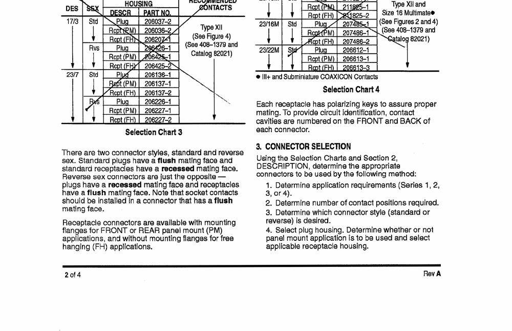
83 Appendix Cable Termination Instructions C C-17

84 Victoreen 942A-200 Operators Manual C-18
85 Appendix Cable Termination Instructions C C-19
86 Victoreen 942A-200 Operators Manual C-20

87 Appendix Cable Termination Instructions C C-21


88 Victoreen 942A-200 Operators Manual C-22

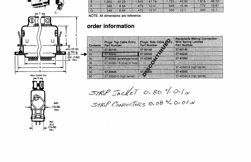
89 Appendix Cable Termination Instructions C C-23
90 Victoreen 942A-200 Operators Manual C-22

91 Appendix Cable Termination Instructions C C-23


92 Victoreen 942A-200 Operators Manual C-24

93 Appendix Cable Termination Instructions C C-25

94 Victoreen 942A-200 Operators Manual C-26

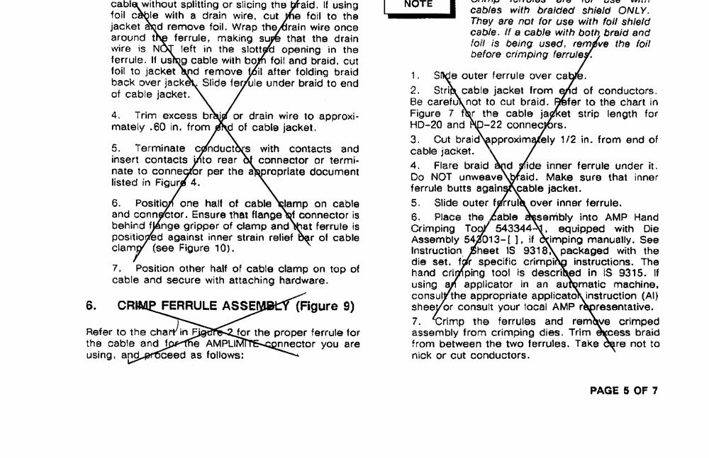
95 Appendix Cable Termination Instructions C C-27
Installation, Operation, and Maintenance Instruction Manual
 Installation, Operation, and Maintenance Instruction Manual Wide-Range Area Monitoring System Model 945A April, 2006, P/N 945A-1, Rev. 13 2006 Fluke Corporation, All rights reserved. Printed in U.S.A.
956A-201-M2 & 897A-2XX Area Monitoring System. Instruction Manual
 956A-201-M2 & 897A-2XX Area Monitoring System Instruction Manual (Blank page) CONTENTS Section 1: GENERAL INFORMATION... 1-1 1.1 Product Specification... 1-1 1.2 Specifications, G-M Detector, Model 897A
Victoreen 942A-200L-M4 Universal Digital Ratemeter with Trip Test and SCA/ Gross Mode Select Switch
 Victoreen 942A-200L-M4 Universal Digital Ratemeter with Trip Test and SCA/ Gross Mode Select Switch 942A-200L-M5 Universal Digital Ratemeter with Trip Test Operator Manual April 2007, August, 2009, October
Victoreen Primalert 35 Area Radiation Monitor
 Victoreen 05-437 Primalert 35 Area Radiation Monitor Operators Manual March 2005 Manual No. 126011 Rev. 3 2003, 2005 Fluke Corporation, All rights reserved. Printed in U.S.A. All product names are trademarks
RTD TEMPERATURE SENSING SYSTEM
 General Overview RTD TEMPERATURE SENSING SYSTEM The Prime Technology RTD Temperature System 9219-00-0002 is a three-channel temperature measuring system that utilizes two RTD Temperature Sensor inputs
Pioneer-R16 Gas Monitor Operator s Manual
 Pioneer-R16 Gas Monitor Operator s Manual Edition 7/2/97 RKI INSTRUMENTS, INC RKI Instruments, Inc. 33248 Central Ave, Union City, CA 94587 (510) 441-5656 Chapter 1: Description About the Pioneer-R16 Gas
Public Safety DAS Annunciator Panel
 Public Safety DAS Annunciator Panel 120 VAC Models: 1221-A, 1221-B, 1221-C Revision D 91117 48 VDC Models: 1221-A-48, 1221-B-48, 1221-C-48 24 VDC Models: 1221A-24, 1221-B-24, 1221-C-24 CAUTION: (Read This
Nuclear Associates
 Nuclear Associates 05-575 MiniMonitor III Multipurpose X and Gamma Ray Survey Meter Operators Manual February 2005 Manual No. 05-575-1 Rev. 2 2004, 2005 Fluke Corporation, All rights reserved. Printed
ESSEX ENGINEERING CORPORATION
 WATER/WASTEWATER TREATMENT CONTROL SYSTEMS AND SUBSYSTEMS 2000 SERIES CONTROL SYSTEMS: 2000 series are for surface mounting inside a control cabinet Model 2024 Electronic Alternator Duplex (two pump) pump
ACCURATE ELECTRONICS INC
 ACCURATE ELECTRONICS INC Page 1 of 7 Model 108078 2 Sept 09 WWW.ACCURATE.ORG PO BOX 1654 97075-1654 8687 SW Hall Blvd 97008 BEAVERTON OR USA 503.641.0118 FAX 503.646.3903 Practice Section 108078 Rev A
Victoreen. Operator Manual. Current Mode Beta Scintillation Detector, Model
 Victoreen Current Mode Beta Scintillation Detector, Model 943-27 Operator Manual February 2007 Manual No. 943-27-31-1, Rev. 3 2007 Fluke Corporation, All rights reserved. Printed in U.S.A. All product
MODEL 8144-RD CLOCK SELECTOR/DISTRIBUTION AMPLIFIER INSTRUCTION MANUAL. SPECTRACOM CORPORATION 95 Methodist Hill Drive, Suite 500 Rochester, NY 14623
 MODEL 8144-RD CLOCK SELECTOR/DISTRIBUTION AMPLIFIER INSTRUCTION MANUAL SPECTRACOM CORPORATION 95 Methodist Hill Drive, Suite 500 Rochester, NY 14623 PHONE 585-321-5800 FAX 585-321-5218 REVISIONS, IF ANY,
Sierra Model 951 Digital Flo-Box. Instruction Manual Part Number IM-951 Revision A 09-05
 Sierra Model 951 Digital Flo-Box Instruction Manual Part Number IM-951 Revision A 09-05 5 Harris Court, Building L Monterey, CA 93940 (831) 373-0200 (800) 866-0200 Fax (831) 373-4402 www.sierrainstruments.com
PORTABLE ISOTOPE IDENTIFIER Search Tool / Sample Counting System
 FEATURES: HIGH GAMMA SENSITIVITY MULTI-CHANNEL ANALYZER (MCA) WORKS WITH VARIETY OF PROBES RADIONUCLIDE LIBRARY TAILORED TO CUSTOMER REQUEST SIMULTANEOUSLY MEASURES ; DISPLAYS; ALARMS 1-3 SEPARATE DETECTORS
ACCURATE ELECTRONICS INC PO BOX SW HALL BLVD BEAVERTON OR USA FAX
 Page 1 of 10 Model 10807800 January 2014 ACCURATE ELECTRONICS INC PO BOX 1654 97075-1654 8687 SW HALL BLVD 97008 BEAVERTON OR USA 503.641.0118 FAX 503.646.3903 WWW.ACCURATE.ORG Practice Section 10807800
Models NFPA 1221-A, NFPA 1221-B Public Safety DAS Annunciator Panel. Revision E 61117
 Models NFPA 1221-A, NFPA 1221-B Public Safety DAS Annunciator Panel Revision E 61117 CAUTION: (Read This First) This panel has been designed to make it nearly bullet proof to mistakes made when wiring
Victoreen & 660-8
 Victoreen 660-6 500-100 6000-100 660-7 & 660-8 CT Probes and Phantoms Operators Manual March 2005 Manual No. 660-6-1 Rev. 3 2004, 2005 Fluke Corporation, All rights reserved. Printed in U.S.A. All product
STATUS ALARM HISTORY ALARM RESET
 Instruction Manual Model 1582-42L Data Switch February 1999, Rev 0 CH1 AUTO CH2 SWITCH 1 2 1 2 STATUS 1 2 MODEL 1582 SWITCH CROSS TECHNOLOGIES INC. CH1 ONLINE MANUAL SELECT CH2 ONLINE SWITCH RESET MAN
DSGH. Radiation-Based Detector with GEN2000 Electronics for Density Measurement QUICK REFERENCE GUIDE
 DSGH Radiation-Based Detector with GEN2000 Electronics for Density Measurement QUICK REFERENCE GUIDE Revision History Revision History Version of manual Description Date 1.0 Initial release 051025 1.1
TECHNICAL DATA OBSOLETE
 Deluge Devices 270a 1. PRODUCT NAME VIKING PAR-3 Available since 1991 2. MANUFACTURED FOR: THE VIKING CORPORATION 210 N. Industrial Park Road Hastings, Michigan 49058 U.S.A. Telephone: (269) 945-9501 (877)
MAINTENANCE & TROUBLESHOOTING GUIDE LEAK ALARM CHANNEL DRY OIL WATER AUX ALARM HIGH LOW CRITICAL WATER TANK LEVEL ALARM MODEL LDE-740 ADVANCE PAPER
 PNEUMERCATOR Liquid Level Control Systems Electronic Systems Excluding LC2000 And TMS Series MAINTENANCE & TROUBLESHOOTING GUIDE 400 300 500 FUEL LEVEL LEAK MONITOR 1 200 600 OIL/GAS NORMAL WATER PNEUMERCATOR
Table of Contents SECTION PAGE SECTION 1 INTRODUCTION Description Features Models... SECTION 2 RS-232 COMMUNICATIONS...
 SECTION Table of Contents SECTION 1 INTRODUCTION...................... 1.1 Description............................... 1.2 Features................................. 1.3 Models..................................
Pump-Down Controller MODEL 4052
 Pump-Down Controller 4-20mA Input/Scalable Output Seal Fail Monitoring Duplex Pump Alternation Hand-Off-Auto Controls Dual Run-time Meters RS-485/Modbus Communications DESCRIPTION The Model 4052 Pump-Down
Pump-Up Controller MODEL 4062
 Pump-Up Controller 4-20mA Input/Scalable Output Seal Fail Monitoring Duplex Pump Alternation Hand-Off-Auto Controls Dual Run-time Meters RS-485/Modbus Communications DESCRIPTION The Model 4062 Pump-Up
Table of Contents SECTION PAGE
 Table of Contents SECTION PAGE SECTION 1 INTRODUCTION................... 1.1 Description.............................. 1.2 Features................................ 1.3 Models.................................
Refrigeration Controller Operator s Manual (HRC) PO Box 6183 Kennewick, WA
 PO Box 6183 Kennewick, WA") Refrigeration Controller Operator s Manual (HRC) PO Box 6183 Kennewick, WA 99336 www.jmcvr.com 1-509-586-9893 Table of Contents TABLE OF FIGURES...1 OVERVIEW OF THE HRC CAPABILITIES...2 INSTALLATION AND
Refrigeration Controller Operator s Manual (HRC) PO Box 6183 Kennewick, WA 99336 www.jmcvr.com 1-509-586-9893 Table of Contents TABLE OF FIGURES...1 OVERVIEW OF THE HRC CAPABILITIES...2 INSTALLATION AND
F PC and AO OUTPUT BOARDS INSTRUCTION MANUAL. Blue-White. Industries, Ltd.
 F-2000 PC and AO OUTPUT BOARDS INSTRUCTION MANUAL Blue-White R Industries, Ltd. 500 Business Drive Huntington Beach, CA 92649 USA Phone: 714-89-8529 FAX: 714-894-9492 E mail: sales@blue-white.com or techsupport@blue-white.com
Table of Contents 1. OVERVIEW SYSTEM LAYOUT SPECIFICATIONS FUNCTION... 11
 Table of Contents 1. OVERVIEW... 3 2. SYSTEM LAYOUT... 4 3. SPECIFICATIONS... 8 3.1 SYSTEM COMPONENTS...9 3.2 PLC INPUTS AND OUTPUTS...9 3.3 FUNCTION KEYS...10 3.4 DEFAULT SET POINTS AND TIMERS...10 4.
Replaceable LED modules. Sleep or unattended mode. Auto-silence and auto-acknowledge
 Replaceable LED modules 11 Alarm Sequences as per ISA-18.1 standard Each channel/window fully field programmable RS232 or RS485 MODBUS-RTU communication Repeat relay for each window and multifunction relays
4100U City and Relay Cards Installation Instructions
 4100U City and Relay Cards Installation Instructions Introduction This publication describes the installation procedure for the following: 4100-6031/6032 City Circuit Cards 4100-6033 Alarm Relay Card Inspecting
INSTRUCTION MANUAL and DETAILED PRODUCT SPECIFICATION TRIPLEX PUMP CONTROL SYSTEM MODEL NUMBER CPC-3. M336 Rev F. November 21, 2000.
 INSTRUCTION MANUAL and DETAILED PRODUCT SPECIFICATION TRIPLEX PUMP CONTROL SYSTEM MODEL NUMBER CPC-3 M336 Rev F November 21, 2000 ÇConsilium Consilium US, Inc. 59 Porter Rd Littleton, MA 01460-1431 USA
Area Monitor/Frisker Count Rate Meter Victoreen
 Area Monitor/Frisker Count Rate Meter Victoreen Model 190F! Adjustable Alarm! Backlit analog/digital display! Interchangeable probe adapter module! Multiple probe use! Redundant power supply! Available
OVEN INDUSTRIES, INC.
 OVEN INDUSTRIES, INC. OPERATING MANUAL Model 5C7-252 TEMPERATURE CONTROLLER With PLC Inputs Introduction Thank you for purchasing our controller. The Model 5C7-252 is an exceptionally versatile unit and
TECHNICAL DATA. Humidity: 85% Relative Humidity (non-condensing) at 90 F (32 C) maximum.
 at 90 F (32 C) maximum.") September 29, 1997 Firecycle III 433 a 1. PRODUCT NAME VIKING Model E-1 Manufactured 1997 Present 2. MANUFACTURED FOR THE VIKING CORPORATION 210 N Industrial Park Road Hastings, Michigan 49058, U.S.A.
September 29, 1997 Firecycle III 433 a 1. PRODUCT NAME VIKING Model E-1 Manufactured 1997 Present 2. MANUFACTURED FOR THE VIKING CORPORATION 210 N Industrial Park Road Hastings, Michigan 49058, U.S.A.
MODEL 8143 SIGNAL SELECTOR INSTALLATION AND OPERATION MANUAL
 MODEL 8143 SIGNAL SELECTOR INSTALLATION AND OPERATION MANUAL 95 Methodist Hill Drive Rochester, NY 14623 Phone: US +1.585.321.5800 Fax: US +1.585.321.5219 www.spectracomcorp.com Part Number 8143-5000-0050
Mark 25 Ultrapure Water Conductivity Analyzer
 Martek Instruments, Inc. Mark 25 Ultrapure Water Conductivity Analyzer Instruction Manual WARRANTY POLICY Unless otherwise stated, MARTEK INSTRUMENTS, INC. warrants this equipment to be free from defects
Model 9010 and 9020 Monitoring Systems
 Model 9010 and 9020 Monitoring Systems Instruction Manual "! WARNING THIS MANUAL MUST BE CAREFULLY READ BY ALL INDIVIDUALS WHO HAVE OR WILL HAVE THE RESPONSIBILITY FOR USING OR SERVICING THE PRODUCT. Like
tcm100, tcm101 Series Temperature Control Modules and PTS100, PTS100/3 Pipe Temperature Sensors Operations Manual
 tcm100, tcm101 Series Temperature Control Modules and PTS100, PTS100/3 Pipe Temperature Sensors Operations Manual This manual covers operation of the tcm100 and tcm101 Series Temperature Control Modules.
HALOGUARD IR MULTI-POINT, COMPOUND SPECIFIC MONITOR INSTRUCTION MANUAL
 HALOGUARD IR MULTI-POINT, COMPOUND SPECIFIC MONITOR INSTRUCTION MANUAL S E R I A L N O. M O D E L N O. T e m p. R a n g e 1 - = > 6 0 o F 2 - = 4 0-6 0 o F 3 - = < 4 0 o F - G a s T y p e 1 - R -1 1 2
MOVING FILTER AIR MONITOR ALPHA, BETA/GAMMA PARTICULATES
 FEATURES: MOVING AIR FILTER AIRBORNE ALPHA LESS RADON AND BETA/GAMMA PARTICULATES RUGGED, 100% DUTY CYCLE SETTABLE ALARM HIGH THROUGH-PUT UNATTENDED OPERATION 12 WEEKS PRINTED RECORD (Optional) 4 CHANNEL
ORP (mv) Controller Model: ORP-XP2. UP DOWN ENTER Time & Date Main Menu Alarm Reset
 Controller Model: ORP-XP2. UP DOWN ENTER Time & Date Main Menu Alarm Reset") Instruction Manual ORP (mv) Controller Model: ORP-XP2 Power Control Alarm Comms UP DOWN ENTER Time & Date Main Menu Alarm Reset Supplied by: Convergent Water Controls Pty Ltd 2/4 Huntley Street, PO Box
Instruction Manual ORP (mv) Controller Model: ORP-XP2 Power Control Alarm Comms UP DOWN ENTER Time & Date Main Menu Alarm Reset Supplied by: Convergent Water Controls Pty Ltd 2/4 Huntley Street, PO Box
Single Point Freeze Protection Heat Trace Control TRACON MODEL FPT 130 Installation and Operation Manual
 We manage heat MANUAL Single Point Freeze Protection Heat Trace Control TRACON MODEL FPT 130 Installation and Operation Manual 1850 N Sheridan Street South Bend, Indiana 46628 (574) 233-1202 or (800) 234-4239
Technical Manual. Level Alarm Unit CARLA & WIDS
 CARLA & WIDS Technical Manual SAS au Capital de 2 158 244-444 871 933 R.C.S. Bourges - APE : 2651B Headquarter : 9, rue Isaac Newton - 18000 Bourges - France Technical Manual CARLA for Tankers Cargo Tanks
MYRIAD TRIPLEX PUMP CONTROLLER INSTRUCTION MANUAL
 MYRIAD TRIPLEX PUMP CONTROLLER INSTRUCTION MANUAL MYRIAD TPC VISIT OUR WEBSITE SIGMACONTROLS.COM MYRIADI&O062705 2 TABLE OF CONTENTS INTRODUCTION 3 Ordering Information Specifications Features WIRING 7,8
MODEL B2 INSTALLATION MANUAL
 RELEASE DEVICES GENERAL DESCRIPTION MODEL B2 INSTALLATION MANUAL S/N: The B2 Series Time Delay Release Devices are UL Listed, Canadian Listed, and CSFM Listed for use on rolling doors, single-slide and
EXTINGUISHING AGENT RELEASE MODULE
 EXTINGUISHING AGENT RELEASE MODULE Operation, Installation & Programming Manual Revision 3.00 Distributors For: 18-20 Brookhollow Ave telephone 02 8850 2888 www.firesense.com.au Baulkham Hills NSW 2153
Instruction Manual WARNING
 Controllers Instruction Manual WARNING THIS MANAUL MUST BE CAREFULLY READ BY ALL INDIVIDUALS WHO HAVE OR WILL HAVE THE RESPONSIBILITY FOR INSTALLING, USING OR SERVICING THIS PRODUCT. Like any piece of
MODEL 5100 VOTING LOGIC MODULE
 DESCRIPTION DESCRIPTION The SST Model 5100 Multi-Input Voting Logic Module is used to monitor the status of up to 14 different points in a hazard zone, and report when a selectable number of these points
CONsOlIDATOR 4 & 8. MulTI- C h ANNEl CONTROllERs. ConsoliDator 4 Model PD940 ConsoliDator 4 Features. ConsoliDator 8 Features.
 CONsOlIDATOR 4 & 8 MulTI- C h ANNEl CONTROllERs ConsoliDator 4 Model PD940 ConsoliDator 4 Features Four 4-20 Four 4-20 Outputs ConsoliDator 8 Features Eight 4-20 Two 4-20 Outputs Common Features Four Pulse
I/A Series 716C 1/16 DIN Temperature Controller
 Product Specifications I/A Series 716C 1/16 DIN Temperature Controller PSS 2C-1B5 A The Foxboro 716C is a powerful compact, 1/16 DIN, microprocessor-based temperature controller that offers a variety of
CELLTROL II BIOREACTOR CONTROL SYSTEM OPERATIONS MANUAL
 Operation Manual Celltrol II Bioreactor Control System Page 1 of 33 Table of Contents 1) Introduction... 3 1.1) Scope of Document... 3 1.2) Control System Overview... 3 1.3) Introduction to Celltrol II...
FIREFLY II PLUS RELEASE DEVICES INSTALLATION MANUAL
 FIREFLY II PLUS RELEASE DEVICES INSTALLATION MANUAL MADE IN THE U.S.A. U.L. LISTED CANADIAN LISTED CSFM: 7300-1418:100 GENERAL DESCRIPTION SERIAL NUMBER The Cookson Company FIREFLY II PLUS Time Delay Release
Instructions R8471J Gas Controller for use with Model OPECL Open Path Eclipse IR Gas Detector 1.1 1/
 Instructions R8471J Gas Controller for use with Model OPECL Open Path Eclipse IR Gas Detector 1.1 1/08 Table Of Contents Section I Installation and Startup.................. 1 INSTALLATION............................................
DIGITAL METERS Large Display Temperature Meters Instruction Manual
 DIGITAL METERS Large Display Temperature Meters PD755 PD756 PD757 Handles Thermocouple & RTD Inputs with Simplicity J, K, T, E, R, & S Thermocouples 100 Ω Platinum RTD (0.00385 or 0.00392 curve) Large
Sierra Series 900 Single & Dual Channel System. Instruction Manual
 Series 240/24 Instruction Manual Table of Contents Sierra Series 900 Single & Dual Channel System Instruction Manual Part Number IM-90-07/05 Revision D. 5 Harris Court, Building L Monterey, CA 93940 (83)
Module Features are-configurable, no module jumpers to set
 December 2011 PACSystems* RX3i Isolated Thermocouple Input Module, 6 Channels, IC695ALG306 Isolated Thermocouple Input Module, 12 Channels, IC695ALG312 Isolated Thermocouple Input module IC695ALG306 provides
CU-02 with Senaco Plus
 CU-02 with Senaco Plus Instruction Manual PL-509 July 2001 U-02 SENACO 33455090 Rev. 1.1 Safety Guidelines Warning notices must be observed to ensure personal safety as well as that of others, and to protect
BS-316. Gas detection control panel up to 16 inputs. Installation operation manual
 BS-316 Gas detection control panel up to 16 inputs Installation operation manual Page 1 from 21 Contents 1 Operation instructions--------------------------------------------------------------------------------------------------------------------3
Model 9010 and 9020 Monitoring Systems
 Model 9010 and 9020 Monitoring Systems Instruction Manual " WARNING THIS MANUAL MUST BE CAREFULLY READ BY ALL INDIVIDUALS WHO HAVE OR WILL HAVE THE RESPONSIBILITY FOR USING OR SERVICING THE PRODUCT. Like
TYPE CM-2201 NELSON SINGLE POINT CIRCUIT MANAGEMENT SYSTEM
 2 Line, 16 Characters/row LCD Display Temperature Input Range -50 C to +500 C -58 F to + 932 F Enclosure NEMA Type 4X Current Rating 30A max (resistive load only) Ambient Temperature -40 C to + 40 C -40
VERTEX VT10 SERIES PID OPERATION MANUAL MICROPROCESSOR BASED PID CONTROLLER
 1 VERTEX VT10 SERIES PID OPERATION MANUAL MICROPROCESSOR BASED PID CONTROLLER 1. INTRODUCTION This manual contains information for the installation and operation and tuning of our Vertex VT10 series self-tuning
DETECTION SYSTEMS. GCM Auto Alarm. Instruction Manual. GA0203P01 Rev. D
 DETECTION SYSTEMS GCM Auto Alarm Instruction Manual GA0203P01 Rev. D Contents Limited Warranty... 3 Warning... 4 Safety Consideration... 4 General Description... 5 Installation... 6 Initial Adjustments...
Table of Contents. T538 Instruction Manual Rev # 6 June R6T538 June rtf E L Switchgear and Control Inc
 Table of Contents Introduction...2 Mounting...2 Dimensions...2 Controls...3 Screen Displays...3 Screen Messages...4 Light Test...5 Control Power...5 Wiring...5 Inputs...7 Outputs...7 Programming...8 Technical
ACSI AO ELECTRIC LATCH RETRACTION CONTROLLER INSTALLATION INSTRUCTIONS I.D. 1089, REV. F
 II 1400-2 ACSI 1406-04-AO ELECTRIC LATCH RETRACTION CONTROLLER INSTALLATION INSTRUCTIONS I.D. 1089, REV. F INSTALLATION Transformer Model BE31763001 by Basler Electric, Transformer Model 2010028 by Galaxy
MADE IN THE U.S.A. ADVANCE FIRE CONTROL MODEL LM21-AFC MANUAL RELEASE DEVICES TEST WEEKLY TO ASSURE PROPER OPERATION OF RELEASE DEVICE/CONTROL PANEL
 RELEASE DEVICES MADE IN THE U.S.A. ADVANCE FIRE CONTROL MODEL LM21-AFC MANUAL The LiftMaster Fire Control (LM21-AFC) Release Device/Control Panel is UL/CUL listed normally energized fail-safe device incorporating
AM-806. Waste/Door Radiation Monitor OPERATIONS MANUAL
 AM-806 Waste/Door Radiation Monitor OPERATIONS MANUAL Section Contents 1. SPECIFICATIONS 2. MAIN COMPONENTS 3. THEORY OF OPERATION 4. OPERATING INSTRUCTIONS 5. INSTALLATION Page 2 1.0 SPECIFICATIONS SENSITIVITY
SAFETY INFORMATION AND WARNINGS
 This manual refers to the Model SST-3 control panel manufactured since October 31, 2013, which uses a universal (100 277 VAC; 50/60 Hz) power supply. Older units use a voltage-specific power supply and
Across-the-Line SERIES MP300 Combined Manual and Automatic
 Across-the-Line SERIES MP300 Combined Manual and Automatic Metron Fire Pump Controllers conform to the latest requirements of National Fire Protection Association s Standard for Centrifugal Fire Pumps
Instruction Manual December 2001 ENACOCU02
 SENACOCU02 Instruction Manual December 2001 ENACOCU02 Safety Guidelines Warning notices must be observed to ensure personal safety as well as that of others, and to protect the product and the connected
THE "SS90" SERIES RELEASE DEVICES MODEL B2 INSTALLATION MANUAL
 S S S S S S S S 90 OLID TATE ECURITIES, INC SOLID STATE FAIL-SAFE UNIT * PATENT PENDING LISTED U 99Y9 RESET L RELEASING DEVICE SOLID STATE SECURITIES, INC. THE "SS90" SERIES RELEASE DEVICES MADE IN THE
Dryer Controller M720
 User Manual Dryer Controller M720 Hardware version 2.00 Software version 2.00 Manual M720 Dryer controller Page 1 of 60 Document history Preliminary version: - Created in April, 2009 Hardware Version 2.00,
ICS Regent. Fire Detector Input Modules PD-6032 (T3419)
") ICS Regent Fire Detector Input Modules (T3419) Issue 1, March, 06 Fire detector input modules provide interfaces for 16 fire detector inputs such as smoke detectors, flame detectors, temperature detectors,
ICS Regent Fire Detector Input Modules (T3419) Issue 1, March, 06 Fire detector input modules provide interfaces for 16 fire detector inputs such as smoke detectors, flame detectors, temperature detectors,
Greentrol Automation, Inc.
 Model GA-100 Technical Manual GreenAlert 100 Series Greentrol Automation, Inc. Installation, Operation and Maintenance Technical Manual GA-100 Document Name: TM_GA-100_R1C TM_GA-100_R1C Part Number: 960--0000
Instruction Manual August sitrans CU 02
 Instruction Manual August 2005 sitrans CU 02 Safety Guidelines: Warning notices must be observed to ensure personal safety as well as that of others, and to protect the product and the connected equipment.
Operating Instructions
 Operating Instructions System 57 5701 CONTROL SYSTEM OPERATING INSTRUCTIONS Helping to make a safer world Ensure that you read and understand these instructions BEFORE operating the equipment. Please pay
Product Manual SZ1145
 Product Manual SZ114 General Purpose Monitor Communicating Controls Description The SZ114 is a microprocessor-based monitoring and alarm interface designed to monitor up to four 1000 Ω platinum temperature
Analog Input Module IC670ALG630
 1 IC670ALG630 The Thermocouple (IC670ALG630) accepts 8 independent thermocouple or millivolt inputs. Module features include: Self calibration Two data acquisition rates based on 50 Hz and 60 Hz line frequencies
Dual Point General Purpose Heat Trace Control TRACON MODEL GPT 230 Installation and Operation Manual
 We manage heat MANUAL Dual Point General Purpose Heat Trace Control TRACON MODEL GPT 230 Installation and Operation Manual 1850 N Sheridan Street South Bend, Indiana 46628 (574) 233-1202 or (800) 234-4239
Speed and Frequency Seite 1 von 7
 Speed and Frequency Seite 1 von 7 E16 Systems for High Safety Speed ing, all with Triple Modular Redundancy. A choice of versions to meet various demands. Compliant with SIL3 / IEC 61508 and/or API 670.
Soft Start Series MP700 Solid State, Reduced Voltage
 Metron Fire Pump Controls and Accessories Soft Start Series MP700 Solid State, Reduced Voltage Metron Fire Pump Controllers conform to the latest requirements of National Fire Protection Association s
Rev 7 06-APR MultiFlex Condensing Unit Board (CUB-II and CUB-TD) Installation and Operation Manual
 Installation and Operation Manual") 026-1705 Rev 7 06-APR-2010 MultiFlex Condensing Unit Board (CUB-II and CUB-TD) Installation and Operation Manual 1640 Airport Road, Suite 104 Kennesaw, GA 31044 Phone: 770-425-2724 Fax: 770-425-9319 ALL
026-1705 Rev 7 06-APR-2010 MultiFlex Condensing Unit Board (CUB-II and CUB-TD) Installation and Operation Manual 1640 Airport Road, Suite 104 Kennesaw, GA 31044 Phone: 770-425-2724 Fax: 770-425-9319 ALL
SCAN200E USER S MANUAL
 SCAN200E USER S MANUAL Code No. 2071 1052 rev. 1.4 Code No. 2071 1052 Rev. 1.4 Page 2/16 SCAN200E User s Manual Foreword This manual is for SCAN200E Controller running software version 2.03 or later. We
USER MANUAL FOR OPERATING SYSTEM
 P2262 ALARM PANEL USER MANUAL FOR OPERATING SYSTEM 21765-07 September 1999 Associated Controls (Aust) PTY. LTD. 29 Smith Street, Hillsdale, NSW, 2036. PH (02) 9311 3255, FAX (02) 9311 3779 Page 1 of 177
Model 6495 Freezing Rain Sensor. User's Manual. All Weather Inc National Drive Sacramento, CA USA
 Model 6495 Freezing Rain Sensor User's Manual All Weather Inc. 1165 National Drive Sacramento, CA 95834 USA 800.824.5873 www.allweatherinc.com Contents Technical Specifications...1 Theory of Operation...2
Controllers. Instruction Manual WARNING
 Controllers Instruction Manual WARNING THIS MANUAL MUST BE CAREFULLY READ BY ALL INDIVIDUALS WHO HAVE OR WILL HAVE THE RESPONSIBILITY FOR INSTALLING, USING OR SERVICING THIS PRODUCT. Like any piece of
Application, Installation, Operation & Maintenance Manual
 APPROVED BY:JBJ PRESCIENT III FIRE ALARM & GAS EXTINGUISHING CONTROL PANEL Application, Installation, Operation & Maintenance Manual PAGE 1 of 43 CONTENTS 1. INTRODUCTION... 3 2. GENERAL DESCRIPTION...
Models LBW-420-LEL (24 VDC powered) Ammonia Leak Detector
 Ammonia Leak Detector") Models LBW-420-LEL (24 VDC powered) Ammonia Leak Detector CAUTION & SYMBOL DEFINITIONS: CAUTION: Gives detailed description of different situations to avoid or not avoid for the proper operation of the
Models LBW-420-LEL (24 VDC powered) Ammonia Leak Detector CAUTION & SYMBOL DEFINITIONS: CAUTION: Gives detailed description of different situations to avoid or not avoid for the proper operation of the
PACSystems* RX3i. Thermocouple Input Module, 12 Channels, IC695ALG412. GFK-2578B October 2011
 October 2011 PACSystems* RX3i Thermocouple Input Module, 12 Channels, IC695ALG412 The PACSystems * Thermocouple Input module IC695ALG412 provides twelve isolated differential thermocouple input channels.
MS-4012/4024 and CMS-4012/4024. Instruction Manual for the. Fire Alarm Control Panels
 R 12 Clintonville Road, Northford, CT 06472 Phone: (203) 484-7161 FAX: (203) 484-7118 Instruction Manual for the MS-4012/4024 and CMS-4012/4024 Fire Alarm Control Panels Document 15586 5/11/93 Revision:
Liquid Helium Level Instruments
 Liquid Helium Level Instruments Versatile Reliable Affordable AMI American Magnetics, Inc. Excellence in Magnetics and Cryogenics Model 135 Liquid Helium Level Monitor... Sample-and-Hold Level Sensing
Alarm Tone Generator Model AG17
 Alarm Tone Generator Installation & Operation P005089 Rev. C 150930 9/30/2015 12:25 PM Ph: 403.258.3100 \ email:info@guardiantelecom.com \ www.guardiantelecom.com Table of Contents Package Contents...
GG-EM ENTRANCE MONITOR. Installation and Operation Manual
 GG-EM ENTRANCE MONITOR Installation and Operation Manual 2 GG-EM Warning Use this product only in the manner described in this manual. If the equipment is used in a manner not specified by Calibration
STATUS ALARM ALARM HISTORY POWER HISTORY RESET
 Instruction Manual Model 1582-70L2 RF Switch June 2011, Rev. D CH1 AUTO CH2 SWITCH 1 2 1 2 STATUS 1 2 MODEL 1582 SWITCH CROSS TECHNOLOGIES INC. CH1 ONLINE MANUAL SELECT CH2 SWITCH MANUAL REMOTE ONLINE
Remote NAC Power Supply D7038
 Operation and Installation Guide Remote NAC Power Supply D7038 D7038 REMOTE NAC POWER SUPPLY Page 2 2005 Bosch Security Systems Contents Contents 1.0 Overview...5 1.1 Module Control...5 1.1.1 Option Bus
User s Guide. CN616 Series 1 4 DIN Economical 6-Zone PID Temperature Controllers. Shop online at omega.com SM
 User s Guide Shop online at omega.com SM e-mail: info@omega.com For latest product manuals: www.omegamanual.info CN616 Series 1 4 DIN Economical 6-Zone PID Temperature Controllers omega.com info@omega.com
PD154 & PD158 VIGILANTE II ANNUNCIATORS Instruction Manual
 PD154 & PD158 VIGILANTE II ANNUNCIATORS 8 Field Selectable Sequences All Common ISA Sequences 4 or 8-Point (Channel) Monitoring Free Replaceable Message Labels Type 4X, NEMA 4X, IP65 Front Universal Power
"SS90" SERIES CONTROLS MODEL C INSTALLATION MANUAL
 S S S SS O L I D S S90 TATE ECURITIES, INC SOLID STATE FAIL-SAFE UNIT * PATENT PENDING LISTED U L 99Y9 RESET RELEASING DEVICE SOLID STATE SECURITIES, INC. "SS90" SERIES CONTROLS MADE IN THE U.S.A. MODEL
SEC 2000 Millenium Infrared Gas Detector
 SEC 2000 Millenium Infrared Gas Detector Instruction and Operation Manual Sensor Electronics Corporation 5500 Lincoln Drive Minneapolis, Minnesota 55436 USA (952) 938-9486 Fax (952) 938-9617 Email: sales@sensorelectronic.com
Fire Extinguishing Control Panel INSTRUCTION MANUAL. Revision 8/ Instruction Manual Page 1 Revision 8/01.17 of 63
 Fire Extinguishing Control Panel FS5200Е INSTRUCTION MANUAL Revision 8/01.17 Instruction Manual Page 1 1. 2. 3. 4. 4.1. 4.2. 4.2.1. 4.2.2. 4.2.3. 4.2.4. 4.2.5. 4.2.6. 4.2.7. 4.2.8. 4.2.9. 4.2.10. 4.2.11.
MODEL FPT-130 SINGLE POINT FREEZE PROTECTION HEAT TRACE CONTROL
 TRACON MODEL FPT-130 SINGLE POINT FREEZE PROTECTION HEAT TRACE CONTROL TABLE OF CONTENTS FPT 130 Overview... 2 Installation... 3 Power Source and Load Connections... 4 Temperature Sensor... 5 External