Liebert LDMF Distribution Monitoring. User Manual
|
|
|
- Marlene Dalton
- 5 years ago
- Views:
Transcription

1 Liebert LDMF Distribution Monitoring User Manual
2
3 TABLE OF CONTENTS IMPORTANT SAFETY INSTRUCTIONS GLOSSARY OF ABBREVIATIONS PRODUCT OVERVIEW MAJOR COMPONENTS PM4 Monitor Board (PMB) PM4 Interface Board (PIB) PM4 Large Interface Board (PLIB) Branch Circuit Monitoring Sensor Module (BSM) Power Supply With EMI Filter Human-Machine Interface/Display Assembly (Optional) PM4 Adapter Board INSTALLATION Installing a BSM (CT Module Assembly) Connecting Panelboards A and B Installing a Solid-Core Current Transformer Installing a Current Transformer on the PIB Interface Board Connecting a Current Transformer to the PM4 Large Interface Board (PLIB) OPERATION Alarms Communication LDMF Setup Port Connection Modbus Connection Downloading the Software Using the Monitor Tool (Used Only for Startup and Diagnostics) Starting the Monitor Tool Monitor Menu Options Panel Status and Real-Time Clock Main Breaker Status Breaker Status Mode Buttons i
4 5.5 Using the Configuration Tool Starting the Configuration Program Main Configuration Window Overview Load a Configuration File from Disk Install Configuration Changes in the Unit Save the Configuration File to Disk Select Panel to View Select Breakers to View Edit the Liebert LDMF Unit Properties Edit the Panel Properties or Set a Password Edit the Breaker Properties Add a Circuit Breaker Adding a Subfeed Breaker Delete a Circuit Breaker/Subfeed Breaker Upgrading the Firmware Display Controls (HMI) Controls and Indicators Liebert LDMF Parameter Screens Liebert LDMF Alarms Liebert LDMF Screens SPECIFICATIONS TROUBLESHOOTING / FREQUENTLY ASKED QUESTIONS FIGURES Figure 1 Main panelboard screens examples Figure 2 Subfeed screens examples Figure 3 Branch breaker screens examples TABLES Table 1 CT matrix for the Liebert LDMF Table 2 Large branch breaker CT wiring Table 3 CT Table for Interface Board Table 4 CT Table for PM4 Large Interface Board # Table 5 CT Table for PM4 Large Interface Board # Table 6 Parameters monitored for breakers Table 7 Alarm conditions and factory setpoints Table 8 Monitor Menu Options Table 9 Monitor mode buttons Table 10 Overview of main Configuration window Table 11 Edit breaker properties and description ii
5 Important Safety Instructions IMPORTANT SAFETY INSTRUCTIONS! WARNING As with all types of electrical equipment, dangerous voltages exist within the equipment where the Liebert LDMF Distribution Monitor components are installed. For maximum safety, ensure power is removed and circuit breakers/disconnects are tagged/locked out per all applicable national, state and local electrical codes prior to working inside equipment. The area around the equipment must be free of any debris or standing water. All power and control wiring must be installed by a qualified electrician in accordance with the NEC and all applicable national, state and local codes. ONLY qualified service personnel should perform maintenance and/or service on the Liebert LDMF system. When performing maintenance and/or service on any component, verify test equipment is insulated and has been inspected prior to use. To avoid damage to the circuit boards, personnel handling these components should be wearing an Electrostatic Discharge strap or other approved protective device. When replacing or installing a solid core Current Transformer (CT), power must be removed from equipment to prevent damage to the CT and/or circuit board. If the CT is a split-core design, follow proper electrical safety procedures and ensure the CT wires are connected to the applicable burdening circuit before attaching the CT around the conductor. These safety precautions are to be used in conjunction with NEC and local/state electrical code. ELECTROMAGNETIC COMPATIBILITY The Liebert LDMF as a functional component of a power distribution and supply product complies with the limits for a class A Digital Device, pursuant to Part 15 of FCC rules. Operation is subject to the following two conditions: This device must not cause harmful interference, and This device must accept any interference received, including interference that may cause undesired operation. Operating this device in a residential area is likely to cause harmful interference that users must correct at their own expense. Liebert LDMF as a functional component of a power distribution and supply product complies with the requirements of EMC Directive 2004/108/EC and the published technical standards. Continued compliance requires installation in accordance with these instructions and use of accessories approved by Emerson Network Power. 1 Liebert LDMF
6 Glossary of Abbreviations 1.0 GLOSSARY OF ABBREVIATIONS The following abbreviations are used in this manual. BCMS BMS BSM DSP GUI HMI IGM LDMF LDMFS LDMFG LDMFI LDMF4 PAB PCD PDU PM4 PIB PLIB PMB STP Branch Circuit Monitoring System Building Management System Branch Sensor Module Digital Signal Processor Graphic User Interface Human-Machine Interface Information Gathering Module Liebert Distribution Monitor Front Access Liebert Distribution Monitor Front (Square-D Panelboards) Liebert Distribution Monitor Front (GE Panelboards) Liebert Distribution Monitor Front (I-Line Panelboards) Liebert Distribution Monitor Front (480V Distribution Cabinets) PM4 Adapter Board Power Conditioning and Distribution Power Distribution Unit Power Monitoring 4th Generation PM4 Interface Board PM4 Large Interface Board PM4 Monitoring Board Service Terminal Port Liebert LDMF 2
7 Product Overview 2.0 PRODUCT OVERVIEW The Liebert LDMF monitors the main panelboard circuit breaker and individual panelboard branch circuit breakers. The measurements are used to report the voltage, current and alarm conditions for each breaker. The Liebert LDMF utilizes branch circuit sensor modules and individual current transformers (CT) to monitor current. In addition, the Liebert LDMF monitors options like subfeed and output circuit breakers and provides a full array of power parameters and alarms. The Liebert LDMF is available as an option for the Liebert PPC, Liebert FDC, Liebert FPC, Liebert RX and Liebert RDC. The Liebert LDMF system can communicate with a Building Management System (BMS) and Liebert SiteScan Web via optional Liebert IntelliSlot cards or Liebert SiteLink interface. The Liebert LDMF consists of a monitor board, interface board, optional local display and Branch Sensor Modules (BSM). The Liebert LDMF is capable of receiving input from current branch sensor modules. The sensor module (BSM) contains 100A current transformers (CTs) encapsulated in an epoxy-filled plastic enclosure designed to be mounted next to the panelboard. Sensor modules are designed to work 3/4" or 1"-spaced panelboards. If a sensor module CT fails, connections are provided for up to six replacement CTs. The optional CTs can be attached directly to the load cable feeding the failed CT. Higher-rated CTs may be used for monitoring optional subfeed circuit breakers. For subfeed breakers, such as main panelboard breakers, the Liebert LDMF monitors not only the three-phase current but also the ground and neutral current. These subfeed circuit breakers are in addition to the panelboard circuit breakers that can be monitored through the BSM. The Liebert LDMF can accommodate 18 individual large current transformers. If your Liebert power center is supplied with a Square D I-Line panelboard, the Liebert LDMF can monitor it as well as its output breakers. A PM4 Large Interface Board (PLIB) replaces the panelboard PM4 Interface Board (PIB) and can monitor up to 42 CTs. Each PLIB can monitor eight four-wire or five-wire I-Line and/or subfeed breakers including ground and neutral current. There are two (2) PLIBs per monitor board that can monitor up to16 five-wire I-Line and/or subfeed breakers. The Liebert LDMF system includes three Liebert IntelliSlot ports for remote communication. Optional Liebert IntelliSlot cards can provide the following remote communications: IS-WEBS card for SNMP/WEB with RJ-45 connection to Ethernet LAN IS-485S card for Modbus 485, 2-wire connection IS-IPBMS card for Modbus IP, with RJ-45 connection to Ethernet LAN IS-UNITY-DP card for HTTP/HTTPS, Emerson Protocol, , SMS, SNMP v1/v2c/v3, BACnet IP/MSTP and Modbus TCP/RTU output using a serial RS-485 two-wire connection The Liebert SiteLink-2E is available as an option with the Liebert LDMF as an interface to Liebert SiteScan. Tools and documentation can be found at the Liebert Web site: Under Service and Support, choose Software Downloads. Click on the link for the LDMF - mm/yyyy Toolkit: where mm/yyyy is the month and year of the update for example, 08/2010 or 11/2012 Note: There are two versions of Liebert Distribution Monitoring software. Be sure to select the LDMF version, which is for units with a setup port labeled LDMF Setup. Do NOT choose the Liebert Distribution Monitoring (LDM) Tool Kit. (The LDM Tool Kit is used on units with a setup port labeled LDM Setup.) Save the file to a desktop or laptop computer (PC) and extract the contents. The software may be updated and changed without any notification. Check the Web site regularly to ensure the software is up-to-date. In addition to Liebert LDMF remote communications, an optional local display offers easy-to-use viewing of electrical data for various branch breakers as well as alarm details such as the type and source of each alarm. 3 Liebert LDMF


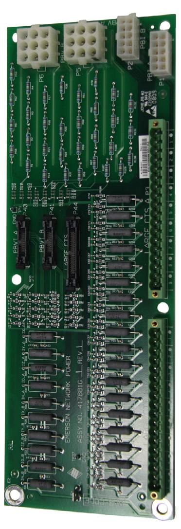
8 Major Components 3.0 MAJOR COMPONENTS 3.1 PM4 Monitor Board (PMB) The PM4 Monitor Board (PMB) is the main processing and storage circuit board. The PMB contains the non-volatile memory where the configuration file is stored. The CT Module Assemblies will connect directly to the PMB via the 4 ribbon cables connectors. The PMB is a DSP-based logic controller with internal flash memory to store breaker configuration, alarms and energy data. The onboard battery supplies power to the real-time clock. All the electrical parameters are accumulated on the PMB for processing to Liebert Velocity protocol for remote monitoring and the HMI interface for the local display. Kilowatt-hours (kwh) data is accumulated on this board for the panelboard mains, subfeeds and each branch circuit breaker. A remote command can be used to reset the accumulated energy data. Additional PMB Capabilities Six (6) auxiliary CT connectors, which allow for replacing a failed CT. A DB9 serial port on the outside panel is available for local configuration. 3.2 PM4 Interface Board (PIB) The Liebert LDMF PM4 Interface Board (PIB) provides connections for the voltage and currents of the panelboard main circuit breaker as well as the CT current for any installed large branches or subfeed breakers (maximum of 18 CTs). For the large branches or subfeed breakers, the nine CTs on the A side of the board are normally associated with the A-side voltages for power calculations. The B-side CTs are normally associated with the B-side voltages. A cross-configuration tool allows changing that association for subfeeds. The 18 large branch CT inputs can also be used to monitor up to three subfeed circuit breakers. This is configured using the configuration tool (see 5.5 Using the Configuration Tool). The CTs from the B side of the PIB are cross-configured to the A side so that the three subfeeds appear within the A-side panelboard register space. The 18 large branch breakers require CT s with 1A secondary. Liebert LDMF 4

9 3.3 PM4 Large Interface Board (PLIB) Major Components! WARNING Before connecting a large CT to the PIB, note the CT MUST have a 1A secondary. Connecting anything other than a 1A secondary CT will damage the PIB and the CT. To ensure the proper current ratio and accuracy, the CTs should be purchased through Emerson Network Power. See Table 1 for details. Contact your local Emerson Network Power representative or call Emerson Network Power Liebert Services at LIEBERT ( ). Table 1 CT matrix for the Liebert LDMF Part Number Description Phase CT Ground CT Neutral CT G1-L 3-pole 0-100A Subfeed Breaker 5W CT Kit 200:1 100:1 200: G2-L 3-pole A Subfeed Breaker 5W CT Kit 500:1 100:1 500: G3-L 3-pole A Subfeed Breaker 5W CT Kit 1000:1 100:1 1000: G12-L 3-pole A Subfeed Breaker 4W CT Kit 500:1 500: G13-L 3-pole A Subfeed Breaker 4W CT Kit 1000:1 1000: G4-L 3-pole 0-100A I-Line Breaker 3W CT Kit 47" Frame 200: G5-L 3-pole A I-Line Breaker 3W CT Kit 47" Frame 500: G6-L 3-pole A I-Line Breaker 3W CT Kit 47" Frame 1000: G7-L 1-pole 0-100A Branch Breaker CT Kit 200:1 The PM4 Large Interface Board (PLIB) provides voltage and current attenuation for Square-D I-Line panelboards. There are 42 CT locations on each LIB for a total capacity of eight 4-wire (3 phases and neutral) or 5-wire (3 phases, neutral and ground) breakers.! WARNING Before connecting a large CT to the PLIB, note the CT MUST have a 1A secondary. Connecting anything other than a 1A secondary CT will damage the PLIB and the CT. To ensure the proper current ratio and accuracy, the CTs should be purchased through Emerson Network Power. See Table 1 for details. Contact your local Emerson Network Power representative or call Liebert Services at LIEBERT ( ). Two PLIBs are supplied for a total maximum monitoring capacity of sixteen 5-wire I-Line and/or subfeed breakers. 5 Liebert LDMF


10 3.4 Branch Circuit Monitoring Sensor Module (BSM) Major Components The Branch Circuit Monitoring Sensor Module (BSM) more commonly referred to as the CT Module contain 21, 27 or 36 individual Current Transformers filled inside an epoxy enclosure. Each load circuit is passed through one of the openings for branch circuit current monitoring. The signals leave the CT module via a ribbon cable which is connected directly to the PM4 Monitor Board (PMB) for attenuation and processing. There are two BSM designs depending on the manufacturer of the panelboard installed: Utilize 1" spacing between circuits. Utilize 3/4" spacing between circuits. The diameter of each CT hole is 0.433" (11mm). Wire diameter and thickness of insulation must be taken into account before wiring each branch circuit. Using wire that is too large may prevent the conductor from fitting through the CT hole. Do not attempt to alter the diameter of the CT opening. For larger panelboards, the CT Module is designed to interlock to maintain alignment between the breaker poles and the CT Modules. 3.5 Power Supply With EMI Filter The power supply assembly converts VAC (+10%/-13% range) 50/60Hz into 12VDC to provide logic level power for the PMB. The Power Supply is fed from the line side of the panelboard main breaker. If during normal operation the panelboard main breaker trips or is turned off, the PMB will still have power to communicate alarms via the local display or remotely via Liebert IntelliSlot cards. Liebert LDMF 6
11 Major Components 3.6 Human-Machine Interface/Display Assembly (Optional) The LDMF allows users to view the panelboard circuit data locally through the optional display. The user interface has function keys to scroll through and view each panelboard's data as well as the associated branch circuits and/or subfeeds. Along with the branch circuit data the LDMF Display also has an alarm annunciation window that lists all active alarms. The display has an LED status indicator that changes to red in the event of an alarm. The Silence/Reset button will silence the audible alarm when pressed once and held until alarm is silenced. When pressed a second time, the button clears the alarm and turns off the red LED. Alarm thresholds cannot be added, deleted or adjusted on the local display. These functions may be performed only by using the LDMF Configuration software, which is available for download at the Liebert Web site. Refer to 5.3 Downloading the Software for downloading instructions and see 5.5 Using the Configuration Tool for details on using the software. 7 Liebert LDMF

12 Major Components 3.7 PM4 Adapter Board The PM4 Adapter Board (PAB) is provided with each Liebert LDMF. The PAB is typically mounted on the back of the display, which is located on the front door of the unit. The PAB provides a customer interface to the LDMF summary alarm contacts. If two Liebert LDMF systems are provided, the two PABs are connected to each other at the factory. It is only necessary to connect to one PAB to monitor the Customer Summary Alarm; the two Liebert LDMF units share summary alarm contacts. On the Liebert FPC and Liebert PPC the PAB has additional connections on TB1 that include Remote Emergency Power Off (EPO). The field-selectable switch S1 on the PAB allows the selection for either Manual or Auto restart. The factory default setting is Manual. Manual restart allows for an orderly supervised startup after power failure. The control circuit automatically energizes the shunt trip mechanism of the main input breaker upon sensing output voltage failure. Setting the switch to Auto deactivates the manual restart. In Auto restart mode, the main input breaker does not trip due to power failure and the unit will restart when power is restored. The TB1 connections for customer alarms 1-5 are used only with the VPMP product. Liebert LDMF 8


13 Installation 4.0 INSTALLATION! WARNING Dangerous voltages exist in power distribution units and power conditioning units. To ensure maximum safety, all circuits breakers in the panelboard should be removed of power and the input feeder breaker should be turned Off and locked-out in accordance with NEC and local/state code. Liebert LDMF components and any other monitoring devices should be installed only by properly trained and qualified personnel. This section provides instructions for installing and connecting Liebert LDMF current transformers. If any Liebert LDMF component requires service, contact Emerson Network Power Liebert Services at LIEBERT ( ) for assistance. 4.1 Installing a BSM (CT Module Assembly) In most cases the BSM the CT Module is factory-installed and no further work is required. If a CT Module must be added, it attaches easily to the side of a panelboard to monitor any combination of 1-, 2- and 3-pole circuit breakers. For side-by-side panelboards (21 circuits on each side), attach one CT Module to each side of the panelboard, ensuring that the center of the CT hole lines up to the branch circuit breaker connection. For Square-D Inline panelboards (42 circuits in a row), the two CT second, lower CT Module so that the two cutout sections line up, then attach the screws to secure the CT Modules to the panelboard. For GE Inline type panelboards, the two CT Modules fit end to end. Flip the second, lower CT Module so that the 50-pin ribbon cable connector, mounted on the bottom of the CT Module, lines up with the hole in the panelboard mounting bracket. Install the circuit breakers according to the manufacturer's documentation. Route the circuit wire through the center of the CT and attach securely to the circuit breaker Connecting Panelboards A and B The CT Module connects to the PMB via a 50-pin ribbon cable attached to the back of the CT Module. Route the ribbon cable and attach to the appropriate connector (see figure at right). There are four connectors that are labeled for easy identification: two for Panelboard A (A1 and A2) and two for Panelboard B (B1 and B2). Connect the CT module that will monitor Circuits 1-21 to the A1 or B1 connector, depending on whether the CT Module is monitoring Panelboard A or B. Connect the CT module that will monitor Circuits to the corresponding A2 or B2 connector. Circuits Monitored Panelboard A Connector Panelboard B Connector 1-21 A1 B A2 B2 To configure the branch circuits, refer to Add a Circuit Breaker. Panelboard A is either Panelboard 1 or Panelboard 3. Panelboard B is either Panelboard 2 or Panelboard 4 depending on which Liebert LDMF Control Board is being configured. 9 Liebert LDMF

14 Installation 4.2 Installing a Solid-Core Current Transformer! WARNING A solid-core CT cannot be installed on a wire while current is flowing through the wire. Damage to the burden resistor and CT will occur. Power must be removed before installing and/or removing any CT. CT s should be installed only by properly trained qualified electricians. The CT for the panelboard main input circuit breaker is hard-wired to the connectors. Removing CT wires from the connector requires a pin extraction tool. Contact Liebert Services at LIEBERT ( ) for assistance. When replacing or installing a CT, ensure that the replacement CT has a secondary rating of 1A for example, 100:1, 200:1, 500:1 or 1000:1. Using a higher-rated CT for example, 100:5 or 500:5-will damage the burden resistors on the PIB board. Typically the three-phase and neutral wires utilize a CT rating of 100:1, 200:1 500:1 or 1000:1, while the ground wire utilizes a CT rating of 100:1. Route the circuit wire through the core of the CT and wire-tie the CT to the cable. Refer to the manufacturer's documentation for proper orientation to ensure accurate readings. When installing CT s for a large branch circuit breaker or subfeed, verify which monitoring board is installed. A PIB can support up to three subfeeds,. One LIB can support up to eight output and/or subfeed breakers. Two LIB boards are provided to support up to 16 output and/or subfeed breakers. Liebert LDMF 10


15 Installation 4.3 Installing a Current Transformer on the PIB Interface Board If subfeed breakers are ordered with the unit, the phase, neutral and ground CTs are wired to the Interface Board.The CTs will be zip-tied inside the equipment for the electrician to install on each conductor when the conductors are wired to the subfeed/large branch breaker. The ground and neutral CTs for each factory-supplied subfeed or large breaker are factory-installed and wired. CTs have a white or H1 that depicts how to position the CT on the cable to ensure accurate readings. The white dot or H1 must face toward the source when installing the CT on the phase cables. The neutral conductor CTs are placed in the opposite direction, with the marking faced toward the load. Route the conductors through the core of the CTs and wire-tie the CT to the cable to ensure the CT stays in place. If subfeed breakers are installed in the field, up to five CTs may be installed (three phases, neutral and ground). The neutral and ground CTs may be omitted if monitoring of neutral and ground is not required. The 5-wire CT kits will be shipped separately and grouped together with each CT with a label indicating whether is a phase CT, neutral CT or ground CT. There are two 18-pin terminal blocks on the Interface Board for large branch circuit breakers and/or subfeeds-one for Panelboard A and one for Panelboard B. The circuit board is marked with a triangle to indicate Pin 1. Pin 1 should be used for the white wire of CT1 (Phase A). The black wire should be connected to Pin 2. The same pattern will follow for the remaining CTs. After all CTs are installed, use the Configuration tool to label and set alarm parameters. To configure the Liebert LDMF, see Add a Circuit Breaker. If the Power Distribution Center is supplied with optional isolated ground, the isolated ground circuit can be monitored by the Liebert LDMF. Usually the CT is already installed and wired to the Large Branch Terminal Block at the factory. If not, perform the following steps: (For Isolated Ground CT Installation only) Connect the isolated ground CT to Pins 17 and 18 on the two 18-pin terminal blocks on the Interface Board. Connect the isolated ground CT white wire to Pin 17 and the CT black wire to Pin 18. Refer to the following example and Table 2 for wiring configuration details. Example: When installing a subfeed breaker where the three phases, neutral and ground will be monitored, the CTs should be wired as follows: Table 2 Large branch breaker CT wiring Pin Wiring 1 Phase A CT White wire 2 Phase A CT Black wire 3 Phase B CT White wire 4 Phase B CT Black wire 5 Phase C CT White wire 6 Phase C CT Black wire 7 Neutral CT White wire 8 Neutral CT Black wire 9 Ground CT White wire 10 Ground CT Black wire If a second subfeed or large branch breaker will be installed, the same pattern will continue. Pins 11 and 12 will be Phase A CT for the second breaker, Pins 13 and 14 will be Phase B CT and so on. 11 Liebert LDMF
16 Installation Table 3 CT Table for Interface Board Configuration 1: Four Modules Position Connector P3 (A) Wire Color B W B W B W B W B W B W B W B W B W CT CT9 or IG CT8 CT7 CT6 CT5 CT14 CT3 CT2 CT1 Position Connector P4 (B) Wire Color B W B W B W B W B W B W B W B W B W CT CT18 or IG CT17 CT16 CT15 CT14 CT13 CT12 CT11 CT10 Configuration 2: Two Modules With Large Branch Breaker CT s Position Connector P3 (A) Wire Color B W B W B W B W B W B W B W B W B W CT LB9 or IG LB8 LB7 LB6 LB5 LB4 LB3 LB2 LB1 Position Connector P4 (B) Wire Color B W B W B W B W B W B W B W B W B W CT LB18 or IG LB17 LB16 LB15 LB14 LB13 LB12 LB11 LB10 Configuration 3: Four Modules With Two 5-Wire Subfeed Breaker CT s Position Connector P3 (A) Connector P4 (B) Wire Color B W B W B W B W B W B W B W B W B W CT LB5 LB4 LB3 LB2 LB1 Phase IG G1 N1 C1 B1 A1 Position Wire Color B W B W B W B W B W B W B W B W B W CT LB10 LB9 LB8 LB7 LB6 Phase IG G2 N2 C2 B2 A2 Configuration 4: Four Modules With Three 5-Wire Subfeed Breaker CT s Position Connector P3 (A) Connector P4 (B) Wire Color B W B W B W B W B W B W B W B W B W CT LB12 LB11 LB5 LB4 LB3 LB2 LB1 Phase IG G3 N3 G1 N1 C1 B1 A1 Position Wire Color B W B W B W B W B W B W B W B W B W CT LB13 LB12 LB11 LB10 LB9 LB8 LB7 LB6 Phase IG C3 B3 A3 G2 N2 C2 B2 A2 Liebert LDMF 12
17 Installation Table 3 CT Table for Interface Board (continued) Configuration 5: Four Modules With Six 3-Wire Subfeed Breaker CT s Position Connector P3 (A) Connector P4 (B) Wire Color B W B W B W B W B W B W B W B W B W CT LB9 LB8 LB7 LB6 LB5 LB4 LB3 LB2 LB1 Phase C3 B3 A3 C2 B2 A2 C1 B1 A1 Position Wire Color B W B W B W B W B W B W B W B W B W CT LB18 LB17 LB16 LB15 LB14 LB13 LB12 LB11 LB10 Phase C6 B6 A6 C5 B5 A5 C4 B4 A4 Configuration 6: Three Modules With Nine Large Branch Breaker CT s Position Connector P3 (A) Connector P4 (B) Wire Color B W B W B W B W B W B W B W B W B W CT LB9 or IG LB8 LB7 LB6 LB5 LB4 LB3 LB2 LB1 Phase C3 B3 A3 C2 B2 A2 C1 B1 A1 Position Wire Color B W B W B W B W B W B W B W B W B W CT C6 B6 A6 C5 B5 A5 C4 B4 A4 W = White B = Black IG = Isolated Ground CT LB = Large Branch Breaker CT A = A Phase CT B = B Phase CT C = C Phase CT N = Neutral CT G = Ground CT 13 Liebert LDMF
18 4.4 Connecting a Current Transformer to the PM4 Large Interface Board (PLIB) Installation PLIB can monitor eight 4-wire or 5-wire output/subfeed breakers. Two LIB boards are provided to support up to 16 output and/or subfeed breakers. If subfeed breakers are ordered with the unit, the phase CTs are installed and wired to the PLIB. The neutral and ground CTs are also factory-supplied and wired to the PLIB as required. CTs have a white dot or H1 marking that depicts how to position the CT to ensure accurate readings. The white dot or H1 marking must face toward the load when installing the CT on the ground and neutral cable. The phase CT's are placed in the opposite direction, with the marking faced toward the source. Route the neutral and ground cable through the core of the specified CT and wire-tie the CT to the cable. If subfeed breakers are installed in the field, up to five CTs may be installed to monitor a subfeed breaker (three phases, neutral and ground). The neutral and ground CTs may be omitted if monitoring of neutral and ground is not required. The designators on the PLIB are different from those on the Interface Board. CT1 (Phase A white wire) begins on TB1 CT1+ and the black wire connects to CT1-. The Ground CT for the first subfeed/output circuit breaker connects to TB4 CT35. The designators on the PLIB are different from those on the Interface Board. CT1 (Phase A white wire) begins on TB1 CT1+ and the black wire connects to CT1-. The Ground CT for the first subfeed/output circuit breaker connects to TB4 CT35. First Breaker Second Breaker CT1+ Phase A CT White wire CT5+ Phase A CT White wire CT1 Phase A CT Black wire CT5 Phase A CT Black wire CT2+ Phase B CT White wire CT6+ Phase B CT White wire CT2 Phase B CT Black wire CT6 Phase B CT Black wire CT3+ Phase C CT White wire CT7+ Phase C CT White wire CT3 Phase C CT Black wire CT7 Phase C CT Black wire CT4+ Neutral CT White wire CT8+ Neutral CT White wire CT4 Neutral CT Black wire CT8 Neutral CT Black wire CT35+ Ground CT White wire CT36+ Ground CT White wire CT35 Ground CT Black wire CT36 Ground CT Black wire If more output or subfeed CTs must be installed, continue in the same pattern shown above. Connect the Phase A CT for the second breaker on CT5 (white wire to CT5+, black to CT5-). Connect the Ground CT for the second breaker to CT36 (white wire to CT36+, black to CT36-). Continue the same pattern until all CT connections are used or there are no more outputs or subfeed CTs to add. Liebert LDMF 14
19 Installation Table 4 CT Table for PM4 Large Interface Board #1 Connector TB1 PCB Label CT9 CT8 CT7 CT6 CT5 CT4 CT3 CT2 CT1 Pins Wire Color B W B W B W B W B W B W B W B W B W CT CT9 CT8 CT7 CT6 CT5 CT4 CT3 CT2 CT1 Phase A3 N2 C2 B2 A2 N1 C1 B1 A1 Connector TB2 PCB Label CT18 CT17 CT16 CT15 CT14 CT13 CT12 CT11 CT10 Pins Wire Color B W B W B W B W B W B W B W B W B W CT CT18 CT17 CT16 CT15 CT14 CT13 CT12 CT11 CT10 Phase B5 A5 N4 C4 B4 A4 N3 C3 B3 Connector TB3 PCB Label CT27 CT26 CT25 CT24 CT23 CT22 CT21 CT20 CT19 Pins Wire Color B W B W B W B W B W B W B W B W B W CT CT27 CT26 CT25 CT24 CT23 CT22 CT21 CT20 CT19 Phase C7 B7 A7 N6 C6 B6 A6 N5 C5 Connector TB4 PCB Label CT36 CT35 CT34 CT33 CT32 CT31 CT30 CT29 CT28 Pins Wire Color B W B W B W B W B W B W B W CT CT2 CT1 NONE NONE CT32 CT31 CT30 CT29 CT28 Phase G2 G1 N8 C8 B8 A8 N7 Connector TB5 W = White B = Black PCB Label CT42 CT41 CT40 CT39 CT38 CT37 Pins Wire Color B W B W B W B W B W B W CT CT8 CT7 CT6 CT5 CT4 CT3 Phase G8 G7 G6 G5 G4 G3 A = A Phase B = B Phase C = C Phase N = Neutral G = Ground 15 Liebert LDMF
20 Installation Table 5 CT Table for PM4 Large Interface Board #2 Connector TB1 PC Label CT9 CT8 CT7 CT6 CT5 CT4 CT3 CT2 CT1 Pins Wire Color B W B W B W B W B W B W B W B W B W CT CT41 CT40 CT39 CT38 CT37 CT36 CT35 CT34 CT33 Phase A11 N10 C10 B10 A10 N9 C9 B9 A9 Connector TB2 PC Label CT18 CT17 CT16 CT15 CT14 CT13 CT12 CT11 CT10 Pins Wire Color B W B W B W B W B W B W B W B W B W CT CT50 CT49 CT48 CT47 CT46 CT45 CT44 CT43 CT42 Phase B13 A13 N12 C12 B12 A12 N11 C11 B11 Connector TB3 PC Label CT27 CT26 CT25 CT24 CT23 CT22 CT21 CT20 CT19 Pins Wire Color B W B W B W B W B W B W B W B W B W CT NONE NONE NONE NONE NONE NONE NONE CT52 CT51 Phase N13 C13 Connector TB4 PC Label CT36 CT35 CT34 CT33 CT32 CT31 CT30 CT29 CT28 Pins Wire Color B W B W B W B W B W B W B W CT CT10 CT9 NONE NONE NONE NONE NONE NONE NONE Phase G10 G9 Connector TB5 W = White B = Black PC Label CT42 CT41 CT40 CT39 CT38 CT37 Pins Wire Color B W B W B W B W B W B W CT NONE NONE NONE CT13 CT12 CT11 Phase G13 G12 G11 A = A Phase B = B Phase C = C Phase N = Neutral G = Ground Liebert LDMF 16
21 Operation 5.0 OPERATION Table 6 The Liebert LDMF is a factory-installed option to provide monitoring of the main breaker, branch circuit breakers and subfeed breakers. It may be installed in the Liebert PPC, Liebert FDC, Liebert FPC. Liebert RX and the Liebert RDC. Software available on the Liebert Web site (see 5.3 Downloading the Software) can be installed on a desktop or laptop computer (PC) to monitor status and configure breaker parameters and alarm setpoints. These monitoring and configuration functions are described in 5.4 Using the Monitor Tool (Used Only for Startup and Diagnostics) and 5.5 Using the Configuration Tool. The Liebert LDMF has an optional local display in conjunction with the remote monitoring capability. The display allows end users to view the panelboard main information as well as each individual branch circuit breaker and/or subfeed data. Alarm status may also be viewed from the local display for up-to-date breaker status. The Liebert LDMF monitors and displays the parameters listed in Table 6. Parameters monitored for breakers Panelboard branch circuit breaker Displayed and monitored for each: Panelboard main circuit breaker and SqD I-Line panelboard Circuit identification and status of each breaker are also displayed. SqD I-Line panelboard circuit breaker Subfeed circuit breaker Parameters Voltage Line-to-line Line-to-neutral Phase Current Neutral Current Ground Current kva kw kw-hours Percent Load Power Factor Crest Factor Voltage Total Harmonic Distortion (THD) Current Total Harmonic Distortion (THD) Before making any changes to an existing configuration or uploading a file to another Liebert LDMF system, make a note of the Software Address. When overwriting an existing configuration file due to changes, modifications or breaker addition/deletion, the Software Address will revert to the value of the file that is loaded. This can lead to incorrect Software Addresses causing Modbus communication errors. 17 Liebert LDMF
22 5.1 Alarms Operation The Liebert LDMF constantly monitors electrical data for each breaker and subfeed. When the unit detects an alarm condition, it annunciates and displays alarm messages via the Monitor program (see 5.4 Using the Monitor Tool (Used Only for Startup and Diagnostics)) as well as showing the alarm on the local display (if installed). Alarms must be manually reset after the alarm condition has been corrected and may be reset through Modbus or by pressing the alarm Silence/Reset button on the front display assembly. To facilitate troubleshooting: All alarms are stored in non-volatile memory to protect against erasure by a power outage. All alarm thresholds for monitored parameters are adjustable by using the Configuration tool to match site requirements (see 5.5 Using the Configuration Tool). Table 7 shows the types of alarms for the various types of breakers, along with a description, factory default setpoints and allowable range for each. Table 7 Alarm conditions and factory setpoints Alarm Description Default setting Range Comments Branch Breakers Overcurrent Warning Current exceeds 75% of breaker amps 15A 0-200% 0% Disables Overcurrent Alarm Current exceeds 80% of breaker amps 16A 0-200% 0% (disables Low Current Alarm Minimum current level of a branch breaker the alarm) 0-70% Panelboard Main Breaker and SqD I-Line Panelboard Phase Overcurrent Warning Current exceeds 75% of breaker amps 170A 0-200% 0% Disables Phase Overcurrent Alarm Current exceeds 80% of breaker amps 180A 0-200% Neutral Overcurrent Alarm Current exceeds 95% of breaker amps 214A 0-200% Ground Overcurrent Alarm Overvoltage Alarm Current exceeds 5 amps (15-125kVA) 5A 1-100A Current exceeds 10 amps ( kVA) 10A 1-100A Current exceeds 15 amps (300kVA) 15A 1-100A Current exceeds 20 amps (450kVA) 20A 1-100A Current exceeds 25 amps (800kVA) 25A 1-100A At least one of the line-to-line voltages exceeds +6% of nominal At least one of the line-to-line or line-to-neutral Undervoltage Alarm voltages falls below -13% of nominal Subfeed Breakers and I-Line Output Breakers 0-50% 0-50% 100% to Disable 100% to Disable Phase Overcurrent Warning Current exceeds 75% of breaker amps 170A 0-200% 0% Disables Phase Overcurrent Alarm Current exceeds 80% of breaker amps 180A 0-200% 0% (disables Low Current Warning Minimum current level of a branch breaker 0-70% the alarm) Neutral Overcurrent Alarm Current exceeds 95% of breaker amps 0-200% Ground Overcurrent Alarm Summary Alarm Panelboard Summary Alarm Current exceeds 5 amps (15-125kVA) 5A 1-100A Current exceeds 10 amps ( kVA) 10A 1-100A Current exceeds 15 amps (300kVA) 15A 1-100A Current exceeds 20 amps (450kVA) 20A 1-100A Current exceeds 25 amps (800kVA) 25A 1-100A Detects and annunciates upon occurrence of any alarm Detects and annunciates upon occurrence of branch or panelboard main breaker alarm Liebert LDMF 18


.")
23 5.2 Communication Operation Connecting locally to the Liebert LDMF Monitoring option requires a female-to-female (F-F) DB9 null modem cable. There will be an external port on the Liebert Power product labeled LDMF SETUP. Connect the DB9 null modem cable to a local PC. Once connected you may run any of the provided software tools that can be downloaded from the Liebert Web site (see 5.3 Downloading the Software) LDMF Setup Port Connection The local LDMF Setup port is not intended to be a service terminal or hyperterminal connection. It is intended only for use of the Liebert LDMF software tools provided. The images above are for illustration only. The location of the external port may vary Modbus Connection Use the Modbus port for remote communication. The Liebert LDMF supports two-wire RS-485 and Ethernet connections (customer-installed). To connect to the Modbus port: Look for Connector RS485 on the IntelliSlot IS-485L card for Modbus 485 or IS-IPBMS card for Modbus IP. Refer to the following figure for proper connection points. RS-232 Port 19 Liebert LDMF
 Configuration - see 5.")

24 Operation 5.3 Downloading the Software The Liebert LDMF has three software tools for monitoring, configuration and firmware updates: Monitoring - see 5.4 Using the Monitor Tool (Used Only for Startup and Diagnostics) Configuration - see 5.5 Using the Configuration Tool These programs may be downloaded at no charge or license fee at the Liebert Web site, Under Service and Support, choose Software Downloads. Click on the link for the LDMF - mm/yyyy Toolkit: where mm/yyyy is the month and year of the update for example, 08/2013 or 11/2014 Note: There are two versions of Liebert Distribution Monitoring software. Be sure to select the LDMF version, which is for units with a setup port labeled LDMF Setup. Do NOT choose the Liebert Distribution Monitoring (LDM) Tool Kit. (The LDM Tool Kit is used on units with a setup port labeled LDM Setup.) Save the file to a computer (PC) and extract the contents. The software may be updated and changed without any notification. Check the Web site regularly to ensure the software is up-to-date. 5.4 Using the Monitor Tool (Used Only for Startup and Diagnostics) The Monitor tool supports a local connection through the LDMF Setup port. The tool displays the following information: Main input voltage and currents Total power Individual branch circuit breaker currents System clock (date and time) Reset kwh function Starting the Monitor Tool If needed, download the latest version of the software (see 5.3 Downloading the Software). Run the executable file Monitor-xx.exe (where xx is the latest version) to start the Monitor tool. In the Connect window, select the appropriate COM port, shown below left. The dialog box lists available ports only. If a port is in use, it does not appear in the list. Click Connect. The Monitoring main window, below right, opens after communication is established. COM port Connect Liebert LDMF 20
25 5.4.2 Monitor Menu Options The Monitor window has a menu bar at the top with a drop-down list of options for each menu. Table 8 summarizes the options available in these menus. Operation Table 8 Monitor Menu Options Menu Option Function File Menu Exit Terminates the monitoring session and closes the Monitor program. View Menu Breakers Updates the status of all branch breakers for the selected panel in the Breaker Status area. Subfeeds Updates the status of all subfeed breakers for the selected panel in the Breaker Status area. Alarms Menu Choose one of three options Raw, Filtered or Latched to specify how alarms are displayed. Note that alarms sent over Modbus are latched independent of changes performed in the Alarms menu. Raw The raw alarm state is the instantaneous state of the alarm. It is not filtered and has no hysteresis. When Raw is selected, an alarm is active whenever the latest reading exceeds the set point and is cleared as soon as the reading returns to a level within the set point range. Filtered The filtered alarm uses the hysteresis interval to suppress transient alarms. A filtered alarm is cleared after the alarm condition remains cleared for longer than the hysteresis interval. Latched Latched alarms behave like filtered alarms that get stuck on. A latched alarm stays active until the alarm is manually cleared. Clear All Clears all latched alarms for the selected panel. Any alarm condition that is still active is latched again after the hysteresis interval passes. Help Menu About Displays information about Liebert Distribution Monitoring Panel Status and Real-Time Clock Menu options The Panel Status area displays: The name of the Liebert LDMF in the Unit box. The currently selected panel in the Panel box. To choose a different panel, click on the panel name or the A/B button. If the selected panel has any active alarms, the panel name appears in white text with a red background. The Real-Time Clock displays the time as stored in the Liebert LDMF unit. The time will not display correctly if the time zone is incorrect in the PC. If the time displayed is incorrect and the problem is not caused by a time-zone configuration problem: Click the Set button to force the real-time clock to synchronize with the time set on the PC. 21 Liebert LDMF
, average power (Power), VA and power factor (PF) for each input phase.")
, as shown above. To clear all metering information, click the Reset All kwh button.")

26 5.4.4 Main Breaker Status Operation The Main Breaker Status area displays RMS current, percent load (PCT), total harmonic distortion (THD), crest factor (CF), line-to-line voltage (VLL-RMS), line-to-neutral voltage (VLN-RMS), average power (Power), VA and power factor (PF) for each input phase. If any phase voltage or current is in alarm, the associated field displays white text with a red background. The metered energy usage for the panel is also displayed in kilowatt hours (kwh), as shown above. To clear all metering information, click the Reset All kwh button.! CAUTION Exercise care before using the Reset All kwh button, which resets the kwh usage for the main breaker as well as all branch breakers and subfeed breakers on the panel Breaker Status The Breaker Status area displays detailed status for every branch or subfeed breaker on the selected panel. The information may appear in table format or in a list with icons indicating status, depending on whether the Table or Icons button is active (see Mode Buttons). The example below left shows the table format with details for each branch breaker: type and rating, percent load, individual phase current in amps (I1, I2, I3), power, apparent power (VA), power factor (PF) and accumulated kilowatt hours (kwh). The example below right shows the icon format. Table view of breaker status Metered energy usage for the panel Icon view of breaker status Mode Buttons Mode buttons at the bottom of the window allow users to toggle the Breaker Status display between subfeed and branch breakers (Subfeeds/Breakers) or between icon and table formats (Icons/Table) and access the Event Log (Events). Table 9 Button Subfeeds/ Breakers Icons/ Table Events Monitor mode buttons Function Toggles between component types in the Breaker Status area: subfeed breakers and branch breakers. The button label changes when the display is changed. Toggles between formats for displaying data in the Breaker Status area: icon view and table view. The button label changes when the display is changed. Displays the Event Log dialog box. Subfeeds/Breakers button Icons/Table button Liebert LDMF 22
.")
27 Operation 5.5 Using the Configuration Tool The Configuration tool allows users to set up breakers and view or change their parameters and alarm setpoints. End users have the ability to modify an existing configuration file by using the Configuration software available on the Liebert Web site, (see 5.3 Downloading the Software). Ensure the existing configuration file is saved locally before making any modifications. Please contact your local Emerson Network Power representative or call Emerson Network Power Liebert Services at LIEBERT ( ) for assistance Starting the Configuration Program Before starting the Configuration tool, decide whether you want to connect to the Liebert LDMF or work in offline mode. Offline mode allows you to run the configuration tool without being connected to the equipment. A configuration file is required for Offline Mode. If one is not available, connect to the equipment locally and save the configuration to disk. See Install Configuration Changes in the Unit and Save the Configuration File to Disk. To Connect via COM Port 1. If needed, download the latest version of the software (see 5.3 Downloading the Software). 2. Connect a PC to the Liebert LDMF via the external DB9 connection. Refer to LDMF Setup Port Connection. 3. Run the file LDMF-Config-xx.exe (where xx is the version number) to start the Configuration program. 4. In the Connect window, select the appropriate COM port from the list of available ports. 5. Click Connect. To Work in Offline Mode 1. If needed, download the latest version of the software (see 5.3 Downloading the Software). 2. Run the file LDMF-Config-xx.exe (where xx is the version number) to start the Configuration program. 3. In the Connect window, click the Work Offline button, shown below. 4. When prompted for the configuration file, navigate to the location of the file. 5. Click Open Connect locally COM port Work offline Proceed to Main Configuration Window Overview to begin configuration. When a local connection to the Liebert LDMF can be performed, load the configuration using the instructions in Load a Configuration File from Disk. 23 Liebert LDMF
28 5.5.2 Main Configuration Window Overview Operation The Configuration window shows breakers graphically in the left pane and associated breaker data at right. Selecting a breaker in the left pane changes the display of data in the right pane. Select Panel Select View Unit Properties Panel Properties Breaker Properties Mode buttons Table 10 shows the main sections of the window, along with a description and a reference to step-bystep instructions for each. Table 10 Overview of main Configuration window Section Function For details, see: Select Panel Toggles the display between Panel A and Panel B Select Panel to View Select View Toggles between Panel and Auxiliary Breakers Select Breakers to View Unit Properties Displays the name and communication settings of the Liebert LDMF unit Edit the Liebert LDMF Unit Properties Panel Properties Displays the name of the selected panelboard; also password setup for security purposes Edit the Panel Properties or Set a Password Breaker Properties Displays breaker parameters and alarm setpoints Edit the Breaker Properties Configuration Mode Buttons Load from File Install to Unit Save to File Uploads a saved configuration file from the PC to the Liebert LDMF. This feature may be used to install a backup copy of a configuration file or set up a new Liebert LDMF installation. Uploads the current configuration from the PC to the Liebert LDMF after making changes to the configuration. This step is required to update the unit with the latest changes. Saves a copy of the configuration file to the PC. This feature is useful when a backup copy of the configuration file is needed Load a Configuration File from Disk Install Configuration Changes in the Unit Save the Configuration File to Disk Exit Now Closes the Configuration program. Liebert LDMF 24


29 5.5.3 Load a Configuration File from Disk A previously saved configuration file created by Emerson Network Power technical personnel or saved from a Liebert LDMF unit may be transferred from a PC to the Liebert LDMF. This feature allows for quick setup based on another unit s configuration or replacing a configuration file in an existing installation. To upload the configuration file: Click on the Load from File button at the bottom of the Configuration window. In the Open window, navigate to the configuration file, then click Open. After a short delay, a confirmation message appears. The Liebert LDMF is now updated with all breaker and subfeed data from the configuration file that was just loaded Install Configuration Changes in the Unit Operation Whenever configuration changes are made using the Configuration program, the changes must be installed in the Liebert LDMF using this procedure. To install changes in the unit: 1. Click on the Install to Unit button at the bottom of the Configuration window. 2. During the upload, the circuit board will reboot and cause a loss of communication with the monitoring products. Install to Unit Once the rebooting process is complete, the configuration is active. Configuration changes are not stored in the Liebert LDMF until the Install to Unit button is clicked Save the Configuration File to Disk Saving the configuration file creates a copy of the current configuration, ensuring a backup is available in the event of file corruption or some other problem. Click on the Save to File button at the bottom of the Configuration window. In the Save As window: Specify the location where you want to save the file in the Save In box. Enter a unique name in the File Name box. Click Save. Load from File Save to File 25 Liebert LDMF
30 5.5.6 Select Panel to View Operation Up to two panelboards may be connected to the Liebert LDMF (see Connecting Panelboards A and B). Each may be viewed in the Configuration main window. To switch the view to a different panel: In the Select Panel box, click on Panel A for Panelboard A or Panel B for Panelboard B. The panel name appears in the Panel Name box, as in the following examples. Select Panel Select View Panel Breakers view Auxiliary Breakers view Select Breakers to View For each panelboard, two types of breakers may be configured. To switch the view, click on a button in the Select View box (shown above): Panel Breakers to view circuit breakers installed in the panelboard (see example above left). Auxiliary Breakers to view breakers installed outside the panelboard for example, subfeed breakers (see example above right). Liebert LDMF 26
31 Operation Edit the Liebert LDMF Unit Properties The Unit properties box displays the name and software address of the Liebert LDMF unit: LDMF Unit Name - a name assigned to the Liebert LDMF unit. To make a change, click Edit and enter a name, then click Apply. Software Address - the address is configured using the communication configuration tool. When finished, click Install to Unit to upload the changes to the Liebert LDMF Unit Properties Panel Properties The configuration changes will not be stored in the Liebert LDMF until the Install to Unit button is clicked. Install to Unit (click to save changes to Liebert LDMF) Edit the Panel Properties or Set a Password 29 The Panel Properties box (see image above) displays the name of the selected panelboard, as well as a Password box for creating a password to protect against unwarranted changes to the configuration: Panel Name - the default panelboard names are PANEL A and PANEL B. To change a name, click Edit and enter a name, then click Apply. Password - a password required for users to make changes to the configuration file. To create a password: Click in the Password box, click Edit and enter a password. The password may be up 10 characters long and may consist of any combination of numbers, letters and special characters. The password is not case-sensitive. Click Apply. When finished, click Install to Unit to upload the changes to the Liebert LDMF. The configuration changes will not be stored in the Liebert LDMF until the Install to Unit button is clicked Liebert LDMF
32 Edit the Breaker Properties The Breaker Properties box displays the breaker name, rating, breaker parameters and alarm settings. Operation Select a Breaker Breaker Properties Edit and Apply buttons Install to Unit (click to save changes to Liebert LDMF) To view or change parameters and alarm settings of a breaker: Click on the breaker in the left pane. When selected, the breaker has a yellow outline. Refer to Table 11 to make changes: Table 11 Edit breaker properties and description Parameter Description To make a change: Breaker Name Position Number of Poles Breaker Rating Phase Overcurrent Alarm Phase Overcurrent Warning Phase Undercurrent Alarm Neutral Current Alarm Ground Current Alarm The name of the selected breaker. The default names are BREAKER #01, BREAKER #02, etc. The location of the selected breaker on the panelboard. The number of poles selected when the breaker was added to the panelboard. The amperage for which the circuit breaker is rated. The default is 20A. Percentage of the breaker rating that triggers an overcurrent alarm. This value must be higher than the Phase Overcurrent Warning. Percentage of the breaker rating that triggers an overcurrent warning. This value must be lower than the Phase Overcurrent Warning. Percentage of the breaker rating that triggers an undercurrent alarm. The default is 0 (zero), which disables the alarm. Percentage of the breaker that triggers a neutral current alarm. Amperage that triggers a ground current alarm. Click in the Breaker Name box, click Edit and enter a name, then click Apply. (Cannot be edited) (Cannot be edited) Click in the Breaker Rating box, click Edit and enter a value, then click Apply. Click in the Phase Overcurrent Alarm box, click Edit and enter a value, then click Apply. Click in the Phase Overcurrent Warning box, click Edit and enter a value, then click Apply. Click in the Phase Undercurrent box, click Edit and enter a value, then click Apply. Click in the Neutral Current Alarm box, click Edit and enter a value, then click Apply. Click in the Ground Current Alarm box, click Edit and enter a value, then click Apply. The configuration changes will not be stored in the Liebert LDMF until the Install to Unit button is clicked. Liebert LDMF 28
33 Add a Circuit Breaker Operation After having an electrician physically install a circuit breaker(s) in the panelboard, use the Configuration software to add the new breaker to the configuration file. Run the configuration program using the steps outlined in Starting the Configuration Program. Once connected, the configuration file that is currently programmed will be displayed. It is highly recommended to save the configuration file to the local PC as a backup prior to making any changes to the configuration file. Perform the steps outlined in Save the Configuration File to Disk before proceeding. Check to make sure the location for the new breaker does NOT have a breaker already assigned. If it does, first remove that breaker assignment (see Delete a Circuit Breaker/Subfeed Breaker), then return to this procedure. An error message appears if you attempt to add a breaker to an assigned position. If NOT assigned, a breaker position is shown with a Liebert logo. An assigned breaker position appears as a picture of a circuit breaker. To add a 1-, 2- or 3-pole circuit breaker: Run the Configuration program (see Starting the Configuration Program). If needed, select the panel and breaker view with the new breaker: In the Select Panel box, click on Panel A or Panel B depending on the panelboard where the new breaker was added. In the Select View box, choose Panel Breakers if the new breaker is installed inside the panelboard (branch breaker) or Auxiliary Breakers if located outside the panelboard (subfeed/output breaker). Add Breaker Assigned breaker positions Unassigned breaker positions Right-click on the new breaker position in the left pane. The selected breaker has a yellow outline. In the pop-up menu, click on Add Breaker and then click on the type of breaker that was installed: One-Pole, Two-Pole or Three-Pole. In the Breaker Properties at right, change the breaker s name, parameters and alarm settings as needed (see Edit the Breaker Properties). When finished, click Install to Unit to upload the changes to the Liebert LDMF. The configuration changes will not be stored in the Liebert LDMF until the Install to Unit button is clicked. 29 Liebert LDMF


34 Operation Adding a Subfeed Breaker Check to make sure the location for the new breaker does NOT have a breaker already assigned. If it does, first remove that breaker assignment (see Delete a Circuit Breaker/Subfeed Breaker), then return to this procedure. An error message appears if you attempt to add a breaker to an already assigned position. If NOT assigned, a subfeed breaker position is shown with three Liebert logos. An assigned subfeed breaker position appears as a picture of a 3-pole breaker. To add a 3-pole subfeed breaker circuit: Run the Configuration program (see Starting the Configuration Program). If needed, select the panel and breaker view with the new breaker: In the Select Panel box, click on Panel A or Panel B. In the Select View box, choose Panel Breakers if the new breaker is installed inside the panelboard or Auxiliary Breakers if located outside the panelboard. Panel Breaker View Auxiliary Breaker View Add Subfeed Assigned breaker positions Unassigned breaker positions Right-click on the new breaker position in the left pane. The selected breaker has a yellow outline. In the pop-up menu, click on Add Subfeed. In the Add Subfeed window: Click on the subfeed for example, Subfeed #1 or Subfeed #2 in the Select Subfeed box. The number of available subfeeds is determined by the interface board selected and whether cross-configuration is enabled. In the Select Size box, choose the rating of the new breaker: 100 Amp, 225 Amp or 400 Amp. Click on the Add Subfeed button to return to the main Configuration window. In the Breaker Properties box of the Configuration window, change the subfeed breaker s name, parameters and alarm setpoints as needed (see Edit the Breaker Properties). When finished, click Install to Unit to upload the changes to the Liebert LDMF. The configuration changes will not be stored in the Liebert LDMF until the Install to Unit button is clicked. Liebert LDMF 30
.")
35 Delete a Circuit Breaker/Subfeed Breaker Operation Removing a breaker from the configuration is required after moving or removing circuit breakers in the panelboard. This step must be performed before adding a breaker in the same position. To delete a breaker: Run the Configuration program (see Starting the Configuration Program). If needed, select the panel and breaker view with the breaker to be deleted: In the Select Panel box, click on Panel A or Panel B. In the Select View box, choose Panel Breakers if the breaker is installed inside the panelboard or Auxiliary Breakers if located outside the panelboard. Right-click on the breaker position in the left pane. The selected breaker has a yellow outline. In the pop-up menu, click Delete. A confirmation message appears, as shown above. Select Yes to delete the breaker (or No to cancel). Repeat as needed to delete other breakers. When finished, click Install to Unit to upload the changes to the Liebert LDMF. The configuration changes will not be stored in the Liebert LDMF until the Install to Unit button is clicked. 31 Liebert LDMF

36 5.6 Upgrading the Firmware The Flash program is used to upgrade the firmware on a Liebert LDMF unit. It uses the service terminal port to erase the old firmware, copy the new firmware and reboot the unit. Updating the firmware will not erase any configuration settings currently installed. Installing a new configuration file will overwrite the Modbus address and settings. Operation To upgrade the firmware: 1. Make sure the Liebert LDMF unit is powered ON. 2. Connect the PC to the Liebert LDMF via the external DB9 connection. Refer to LDMF Setup Port Connection. 3. Run the file named Flash-x.x.x.exe (where x.x.x is the version number). 4. In the Upgrade Firmware window, click the Select Port button. Liebert LDMF 32

.")
37 Operation 5. In the Scan for LDM Units window: Select the COM port from the drop-down list for example, COM1. Make sure the Baud Rate is Click the Start Scan button to check for a connection to the unit. 6. If the Liebert LDMF unit is detected, a confirmation window appears. Click Yes to continue and proceed to Step 7. If the Liebert LDMF unit is NOT detected, an error message appears. Click OK to return to the Upgrade Firmware window. Check to verify the following, then repeat Step 5: The correct COM Port is selected and the Baud Rate is A serial cable is properly connected to the unit (see LDMF Setup Port Connection). The Liebert LDMF unit is powered ON. 33 Liebert LDMF


, and the Open window appears (below right).")
38 Operation 7. Verify the Upgrade Firmware window displays the following indications that the connection was successful (shown in the example below): In the Summary Status box, the Number of Units should be 1 in the Found box. In the Detail Status box, 0 should appear in the Address column. The Select Port, Download, Quick Flash, and Cancel buttons are grayed-out Connection Successful 8. Click the Image File button (below left), and the Open window appears (below right). Browse to the folder where the Flash files are located this should be the same folder where the Flash Program was installed. Select the file you want to download. Click the Open button. Image File button Navigate to File Liebert LDMF 34


39 Operation 9. The Upgrade Firmware window appears. Click the Download button to continue. 10. Wait for the firmware upgrade to complete. The Progress column in the Detail Status Area shows the status of the upgrade. The program erases the old image (below left), than writes the new image (below right). Progress column Failed = When the new image is loaded, the Flash program restarts the unit. Verify the following: In the Summary Status box, the Number of Units should be 0 under Failed (above right). In the Detail Status box, Running should appear in the Progress column this indicates that the BCB has been restarted successfully. 12. The Flash program has a Quick Flash feature that keeps track of where the file is stored on the local PC. This feature becomes active after the initial firmware update has been completed. This makes upgrading numerous LDMF Systems easier and less time-consuming. Connect to each additional LDMF System, then click on the QuickFlash button to begin the update automatically without having to specify the file location. QuickFlash button 13. Once all LDMF Systems have been upgraded, click Exit to close the Flash program. 35 Liebert LDMF

40 5.7 Display Controls (HMI) Operation The Liebert LDMF displays panelboard data via a local display in conjunction with the remote capabilities. This display gives the end user a quick and easy way of viewing the panelboard branch circuit breaker currents, panelboard voltages, alarms and status. An audible alarm is also provided in the event that any programmed alarm threshold is exceeded. The user interface and menu selections have been developed to make it easy to scroll through panelboard data points with clearly labeled variable function keys. These function keys change features depending on the menu selected to maintain a clearly visible view area. There can be up to two HMI s on a unit and each can display up to four panelboards Controls and Indicators The left side of the display includes indicators and an alarm speaker: Power Indicator (Green LED) - illuminates when power has been applied to the Liebert Power product. Alarm Status Indicator (Red LED - illuminates when the Liebert LDMF detects an alarm. The audible alarm will also sound until the Silence/Reset push button is depressed. The LED will remain illuminated until the alarm condition is cleared. Audible Alarm speaker (represented by the white dot) - a speaker behind the bezel will sound when the Liebert LDMF records an alarm condition. Pressing the Silence/Reset push button mutes the audible alarm until another alarm is generated or the alarm condition has cleared. The middle section includes the display area and navigation keys to change the display: LCD viewing area - displays parametric or alarm data for selected components Navigation keys (soft function keys F1 through F4 and Help) some of these keys vary in function, as indicated in the text description above each key: F1 selects the next major item such as Next Main, Next Subfeed, or Next Branches. F2 is the Sequence key. It selects the next set of items at the current level or the next item on a list. F3 can select Subfeeds at the top level or can select a menu item at lower levels. F4 can select Branch Breakers at the top level or provide a Back function at lower levels. Pressing the Back key (F4) navigates to the top level (Main) except from the Help screen. From the Help screen, the Back key navigates to the previous screen. Pressing the Help key navigates to the Help screen. At right is the alarm Silence/Reset button: Press the Silence/Reset button once and hold to silence the audible alarm. Press the Silence/Reset button a second time to clear the alarm and turn off the red LED. Power Indicator Green Alarm Status Indicator Red Audible Alarm speaker LCD viewing area Navigation keys Alarm Silence/Reset push button Liebert LDMF 36

41 5.7.2 Liebert LDMF Parameter Screens Operation Three types of parameter screens may be selected from the Main Screen by pressing the soft keys labeled Next Main, Subfeeds and Branch Breakers to display the applicable information. Next Main Subfeeds Branch Breakers Next Main Press the Next Main key to display parameters for the main breaker feeding power to a panelboard. There may or may not be a physical circuit breaker installed. The Next Main key toggles between the two Main Panelboard breakers in a Liebert Power product with more than one panelboard. Subfeeds Press the Subfeeds key to show parameters for subfeed breakers these are usually circuit breakers that feed remote circuits or panelboards. They may reside as separate entities within a Liebert Power product or a special large panelboard. Branch Breakers Press the Branch Breakers key to view parameters for one-, two- or three-pole circuit breakers that reside in the panelboard. The branch data resides at the lowest level except for the alarm summary Liebert LDMF Alarms If any alarms are present when parameter screens are accessed with the Main, Subfeeds or Branch Breakers keys, the Alarm Screen appears, as shown in the example below. Press F4 (Back) to view details about the alarm on the Panelboard Main screen. The alarm activates the Audible Alarm and the red Alarm LED. Press the Silence/Reset key once to silence the audible alarm. Press the Silence/Reset key a second time to clear the alarm. If all alarms are reset, the display returns to the Main Alarm screen. If the alarm condition persists, a new alarm is generated and the sequence is repeated. NEW ALARM(S) PRESENT PRESS THE SILENCE/RESET KEY TO RESET THE ALARM(S) PRESS BACK TO GO TO THE PANEL BOARD MAIN TO REVIEW THE ALARM TYPE(S) AND LOCATION(S) s BACK F1 F2 F3 F4 HELP 37 Liebert LDMF
Liebert PPC Second Generation Power Distribution Cabinet
 Liebert PPC Second Generation Power Distribution Cabinet Emerson Network Power Delivers The Packaged Power Solution Creating high quality power is a major step towards protecting the operation of a critical
UltraLITE Model ELU Centralized Emergency Lighting Inverter 4.2 KW- 5 KW
 12/23/16 Rev 9 UltraLITE Model ELU General Specification 4.2 KW to 5 KW UltraLITE Model ELU Centralized Emergency Lighting Inverter 4.2 KW- 5 KW 1.0 General General Specification This specification describes
PowerLogic ION Setup Meter Configuration Software Configuration Guide
 PowerLogic ION Setup Meter Configuration Software Configuration Guide 70002-0293-03 12/2010 Conventions Used in this Manual This section describes the symbols and terminology used in this guide. Symbols
APC BC300 Series 40kW 208/450/480V User Guide
 APC BC300 Series 40kW 208/450/480V User Guide Copyright 2002 APC Denmark ApS This manual is subject to change without notice and does not represent a commitment on the part of the vendor Thank You Thank
Spa Touch Control Panel with BP2100, BP6013 spa controllers. (Spa Owner s Manual insert)
") Spa Touch Control Panel with BP2100, BP6013 spa controllers. (Spa Owner s Manual insert) P.N. 7876C (export) February 12, 2015 For Spas equipped with BP2100, BP6013 controllers and Spa Touch panel. Spa
Spa Touch Control Panel with BP2100, BP6013 spa controllers. (Spa Owner s Manual insert) P.N. 7876C (export) February 12, 2015 For Spas equipped with BP2100, BP6013 controllers and Spa Touch panel. Spa
21-light Remote Annunciator. Owner s Manual
 21-light Remote Annunciator Owner s Manual Annunciator Description... Inside Font Cover Detailed Specifications... 1 Environmental Specifications... 1 Power Supply Requirements... 1 Communication With
CALTECH Pasadena, CA
 CALTECH Pasadena, CA Power Distribution Unit 225kVA PDU with (3) 42ckt Panel Distribution ILL OF MATERIAL ITEM 3 Eaton Powerware - Power Distribution Unit (PDU) Qty (3) - 225kVA Power Distribution Unit
PowerLogic Branch Circuit Power Meter (BCPM)
") PowerLogic Branch Circuit Power Meter (BCPM) Panel Board Monitoring System Installation Guide Branch Circuit Power Meter (BCPM) HAZARD CATEGORIES AND SPECIAL SYMBOLS Read these instructions carefully and
PowerLogic Branch Circuit Power Meter (BCPM) Panel Board Monitoring System Installation Guide Branch Circuit Power Meter (BCPM) HAZARD CATEGORIES AND SPECIAL SYMBOLS Read these instructions carefully and
Spa Touch Control Panel with 2000, 2100 controllers. (Spa Owner s Manual insert)
") Spa Touch Control Panel with 2000, 2100 controllers (Spa Owner s Manual insert) P.N. 7876B February 11, 2015 For Spas equipped with BP2000, BP2100 controllers and Spa Touch panel. Spa Touch Control Panel
Spa Touch Control Panel with 2000, 2100 controllers (Spa Owner s Manual insert) P.N. 7876B February 11, 2015 For Spas equipped with BP2000, BP2100 controllers and Spa Touch panel. Spa Touch Control Panel
LORAIN CIP 4890/48120 DC Power System
 DC Power for Business-Critical Continuity Key Features Compact flexibility provides rectifiers, distribution, and controller in one shelf Constant power delivers more current at lower voltages to meet
IntesisBox BACnet/IP Server - Notifier ID3000 series
 IntesisBox Server - Notifier ID3000 series Gateway for integration of Notifier ID3000, ID3002, ID50 and ID60 fire panels into enabled control systems. Integrate your Notifier fire panels into your BACnet
INSTALLATION INSTRUCTIONS
 TT-1343 5/06b INSTALLATION INSTRUCTIONS Original Issue Date: 8/03 Model: Automatic Transfer Switches Equipped with Series 1000 Programmable Controller Market: ATS Subject: Remote Annunciator Kits GM28938-KP1,
ACTIVE INFRARED BARRIER
 Although PROTECH provides high security indoor intrusion sensors for the military and government markets, our specialty is outdoor protection. Since we first introduced our PIRAMID outdoor dual technology
Adaptive CyCLO Technical and HMI User Guide. CyCLO User Guide. Version th December 2017 REV
 CyCLO User Guide Version 2.00 19 th December 2017 REV 2.00 1 Contents 1. Hardware... 3 1.1. Introduction... 3 1.2. Electrical Specification... 3 1.3. Board Overview... 4 1.4. Electrical Installation...
Alarm Panel [ PRELIMINARY HARDWARE MANUAL ] USER MANUAL. v1.0a. May 7, 2008 D-OC-UM
![Alarm Panel [ PRELIMINARY HARDWARE MANUAL ] USER MANUAL. v1.0a. May 7, 2008 D-OC-UM](/thumbs/86/93788073.jpg "Alarm Panel [ PRELIMINARY HARDWARE MANUAL ] USER MANUAL. v1.0a. May 7, 2008 D-OC-UM") Alarm Panel USER MANUAL [ PRELIMINARY HARDWARE MANUAL ] Visit our website at www.dpstelecom.com for the latest PDF manual and FAQs. May 7, 2008 D-OC-UM085.07010 v1.0a Revision History April 28, 2008 May
Alarm Panel USER MANUAL [ PRELIMINARY HARDWARE MANUAL ] Visit our website at www.dpstelecom.com for the latest PDF manual and FAQs. May 7, 2008 D-OC-UM085.07010 v1.0a Revision History April 28, 2008 May
LORAIN CSP DC Power System
 DC Power for Business-Critical Continuity Key Features Compact flexibility provides more space for revenue generating equipment Constant power delivers more current at lower voltages to meet load or recharge
ModSync Sequencing System Installation & Operation Manual. For use with Fulton Steam Boilers.
 ModSync Sequencing System Installation & Operation Manual For use with Fulton Steam Boilers. Revision 3.0 8/21/2008 - 2 - Table of Contents Introduction Page 4 Features Page 4 Sequence of Operation Page
PowerWizard. Level 1.0 & Level 2.0 Control Systems Training
 PowerWizard Level 1.0 & Level 2.0 Control Systems Training New Systems Current Systems Systems Comparison Level 1 Level 2 Level 3 Level 4 PowerWizard Level 3.0 PowerWizard Level 4.0 Overview Common parts
AGC 200 Advanced Gen-set Controller OPERATOR S MANUAL
 Advanced Gen-set Controller OPERATOR S MANUAL Display readings Push-button functions Alarm handling Log list Document no.: 4189340607A SW version 3.5X.X or later Table of contents 1. ABOUT THIS DOCUMENT...3
Installation Manual. ATS Remote Annunciator Catalog 5350 DANGER WARNING D
 ASCO 5350 The ASCO 5350 ATS Remote Annunciator is listed under the Underwriter s Laboratories Standard UL-1008 for Automatic Transfer Switch accessories. This stand-alone device provides individual status
Section PERIMETER SECURITY SYSTEMS
 Section 28 16 43 PERIMETER SECURITY SYSTEMS PART 1 GENERAL 1.1 SUMMARY A. Provide and install a perimeter security system as herein specified for the purpose of detecting entry into a designated security
elite Model ELN Centralized Emergency Lighting Inverter Systems 550 W to 1.5 KW Systems
 5/25/16 rev 6 elite Model ELN General Specification 550 W to 1.5 KW elite Model ELN Centralized Emergency Lighting Inverter Systems 550 W to 1.5 KW Systems 1.0 General General Specification This specification
TYPE CM-2201 NELSON SINGLE POINT CIRCUIT MANAGEMENT SYSTEM
 2 Line, 16 Characters/row LCD Display Temperature Input Range -50 C to +500 C -58 F to + 932 F Enclosure NEMA Type 4X Current Rating 30A max (resistive load only) Ambient Temperature -40 C to + 40 C -40
1.1 Remote Annunciator Controller (RAC) using the one ATC-300+ connected via RS-485 network.
 using the one ATC-300+ connected via RS-485 network.") Remote Annunciator Controller (RAC) Instruction Sheet for Automatic Transfer Switches (ATS) Revision: 01 IB01602085E 1.1 Remote Annunciator Controller (RAC) using the one ATC-300+ connected via RS-485
Remote Annunciator Controller (RAC) Instruction Sheet for Automatic Transfer Switches (ATS) Revision: 01 IB01602085E 1.1 Remote Annunciator Controller (RAC) using the one ATC-300+ connected via RS-485
Laptop / PC Programming Manual
 Laptop / PC Programming Manual Doc. # Fire PC Program rev B 01.07 This Document is property of Evax Systems, Inc. The Evax Fire Solutions Programmer Components 2 1.0 System Setup 4 1.1 Interface Setup
Powerohm Resistors Digital HRG System
 Installation and Operating Instructions Powerohm Resistors Digital HRG System This manual provides general information, installation, operation, maintenance, and system setup information for the Powerohm
MODEL GPT-130 SINGLE POINT HEAT TRACE CONTROL THERMOSTAT
 TRACON MODEL GPT-130 SINGLE POINT HEAT TRACE CONTROL THERMOSTAT TABLE OF CONTENTS GPT 130 Overview... 2 Installation... 3 Power Source and Load Connection... 4 Temperature Sensor Installation... 5 Panel
T M. User Manual. MarinaGuard. Ground Fault Monitoring Panel For Marina Shore Power
 T M User Manual MarinaGuard Ground Fault Monitoring Panel For Marina Shore Power NAE1095810 / 03.2013 T M Bender Inc. USA: 700 Fox Chase Coatesville, PA 19320 Toll-Free: 800-356-4266 Phone: 610-383-9200
Complex alarming made simple
 SEL-2523 Annunciator Panel Complex alarming made simple Superbright LEDs provide easily visible alarm indication in any lighting condition. Sequential Events Recorder (SER) data help identify the root
DGC-1000 DIGITAL GENSET CONTROLLER
 DGC-1000 DIGITAL GENSET CONTROLLER Basler Electric s Digital Genset Controller (DGC-1000) offers a low cost microprocessor based integrated alternative for small to medium sized genset control and monitoring.
Operating & Maintenance Manual. Alert-4 Ethernet LCD Master Alarm
 Operating & Maintenance Manual Alert-4 Ethernet LCD Master Alarm w w w. a m i c o. c o m Contents User Responsibility 4 Introduction 4 Features 5 Description of the Alarm 5 Shipment Details 5 The Alarm
Across-the-Line SERIES MP300 Combined Manual and Automatic
 Across-the-Line SERIES MP300 Combined Manual and Automatic Metron Fire Pump Controllers conform to the latest requirements of National Fire Protection Association s Standard for Centrifugal Fire Pumps
1.1 Ethernet Remote Annunciator Controller (RAC) using the up to 4 ATC-300+ connected via RS-485 to TCP/IP gateway
 using the up to 4 ATC-300+ connected via RS-485 to TCP/IP gateway") Ethernet Remote Annunciator Controller (RAC) Instruction Sheet for Automatic Transfer Switches (4 x ATS) Revision: 01 IB01602082E 1.1 Ethernet Remote Annunciator Controller (RAC) using the up to 4 ATC-300+
Ethernet Remote Annunciator Controller (RAC) Instruction Sheet for Automatic Transfer Switches (4 x ATS) Revision: 01 IB01602082E 1.1 Ethernet Remote Annunciator Controller (RAC) using the up to 4 ATC-300+
SLATE. Base Module INSTALLATION INSTRUCTIONS R8001A1001
 SLATE Base Module R8001A1001 INSTALLATION INSTRUCTIONS Scan for more information Application SLATE brings configurable safety and programmable logic together into one single platform. The platform can
Centaur TM II Cube Slave Alarm Signalling Equipment INSTALLATION GUIDE
 Centaur TM II Cube Slave Alarm Signalling Equipment INSTALLATION GUIDE General Description This guide provides a summary for installing and configuring the Centaur TM Cube Slave Alarm Signalling Equipment
Flopurge TS. Operation Manual
 Flopurge TS Operation Manual Part Number 079-0204 Spectron Gas Control Systems United Kingdom Unit 4, Herald Court, University of Warwick Science Park, Coventry, CV4 7EZ +44 (0)24 7641 6234 sales@spectron-gcs.com
Added password for IP setup page : Password must be in IP format!
 NETWORK POWER MONITOR Release : 21 August 2014 Hardware Version : Version 7 Firmware version 1.00 PC Application Software : Version (latest)...2 Added password for IP setup page : Password must be in IP
RF SCOUT PLUS INSTRUCTION MANUAL. Dielectric, LLC 22 Tower Rd. Raymond, ME Phone: January 2015, Rev B 1
 RF SCOUT PLUS INSTRUCTION MANUAL Dielectric, LLC 22 Tower Rd. Raymond, ME 04071 Phone: 800.341.9678 www.dielectric.com 21 January 2015, Rev B 1 WARNING Powering RF sensors above +30dBm (1W) will cause
Soft Start Series MP700 Solid State, Reduced Voltage
 Metron Fire Pump Controls and Accessories Soft Start Series MP700 Solid State, Reduced Voltage Metron Fire Pump Controllers conform to the latest requirements of National Fire Protection Association s
D8024, D9024, D10024 Analog Fire Alarm Control Panels Programming Guide
 System Reset Trou ble Silence Ala rm Silence Manual Ala rm ENTER NO YES Letters Numb ers Keyword Radionics System Reset Trouble Silence Alarm Silence Manual Alarm ENTER NO YES Le ters Numbers Keyw ord
Flostop TS D7E and A8E. Operation Manual
 Flostop TS D7E and A8E Operation Manual United Kingdom Spectron Gas Control Systems Ltd, Unit 4, ATU1, University of Warwick science Park, Coventry, +44 (0) 24 7641 6234 sales@spectron-gcs.com Germany
Replaceable LED modules. Sleep or unattended mode. Auto-silence and auto-acknowledge
 Replaceable LED modules 11 Alarm Sequences as per ISA-18.1 standard Each channel/window fully field programmable RS232 or RS485 MODBUS-RTU communication Repeat relay for each window and multifunction relays
Diagnostics and Monitoring System WEB Tool 2. User Manual
 Diagnostics and Monitoring System 2 (Translation of the original documentation) User Manual S/N: Valid from: 01.05.2012 Rev.: 2.0 2 Rev. 1.... 1 1.1 General information... 1 1.1.1 Equipment... 1 1.1.2
Pioneer-R16 Gas Monitor Operator s Manual
 Pioneer-R16 Gas Monitor Operator s Manual Edition 7/2/97 RKI INSTRUMENTS, INC RKI Instruments, Inc. 33248 Central Ave, Union City, CA 94587 (510) 441-5656 Chapter 1: Description About the Pioneer-R16 Gas
Entwicklung + Fertigung + Service: Heerweg 15 D, Denkendorf Tel.: / Fax.: /
 Planungsbüro + Service: Esteraustr. 10, 56379 Holzappel Tel.: 0 64 39 / 90 19 90 Fax.: 0 64 39 / 90 19 91 E-Mail: u.ramakers@umsitec.de Entwicklung + Fertigung + Service: Heerweg 15 D, 73770 Denkendorf
TE809-Ats Instructions Manual
 TE809-Ats Instructions Manual Project: v2.0 PREFACE Thanking you for preference, TECNOELETTRA SRL hopes that the use of this equipment could be a reason of satisfaction. This manual is designed to put
M3092 Programmer. User s Manual. M3096B-33 E Copyright 2017 SELCO
 User s Manual Copyright 2017 SELCO SELCO Betonvej 11 - DK-4000 Roskilde Denmark Phone: 45 7026 1122 - Fax: 45 7026 2522 e-mail: selco@selco.com www.selco.com Table of contents 1 INTRODUCTION...4 2 SOFTWARE
LiteMinder. LM Series Inverter Pure Sine Wave Modular Inverter Technology. Fast Transfer System 1.0 to 18.75KVA LED Compatible
 LiteMinder Fast Transfer System 1.0 to 18.75KVA LED Compatible Series Pure Sine Wave Modular Technology Modular AC System Evenlite s LiteMinder Central System provides an innovative Emergency Lighting
Ion Gateway Cellular Gateway and Wireless Sensors
 Page 1 of 9 Account & Network Setup If this is your first time using the Ion Gateway online system site you will need to create a new account. If you have already created an account you can skip to the
Operation Manual Fighter ProVision Software. Version: 0.0 Revision: 1
 Operation Manual Fighter ProVision Software Version: 0.0 Revision: 1 TABLE OF CONTENTS 1. Introduction 5 2. Software Installation 5 3. PC Users 6 3.1 Introduction 6 3.2 Default Code 6 3.3 Edit PC User
Model A2100 Series Annunciator
 Seekirk Model A2100 Series Annunciator Applications: For usage within transformers, switchgear, breakers and/or within any processing equipment or control room applications either attended or unattended
1S25. Arc Fault Monitor 4 Zones, 8 Sensors. Features. Introduction. ARC Fault Protection
 Technical Bulletin Arc Fault Monitor 4 Zones, 8 Sensors Features Four independent arc fault tripping zones 1 or 2 arc fault sensors per zone allowing up to 8 arc fault sensors per module Trip indication
User s Manual. TIGER S EYE E-Series Mark V Jockey. TIGERFLOW Systems, Inc Mint Way Dallas, Texas
 User s Manual TIGER S EYE E-Series Mark V Jockey TIGERFLOW Systems, Inc. 4034 Mint Way Dallas, Texas 75237 214-337-8780 www.tigerflow.com TABLE OF CONTENTS Introduction... 4 Sequence of Operation... 5
Centroid Snet 2. Battery Management Software. User Manual V1.1. Eagle Eye Power Solutions, LLC Keeping an Eye on Your Critical Power!
 Eagle Eye Power Solutions, LLC Keeping an Eye on Your Critical Power! Centroid Snet 2 Battery Management Software User Manual V1.1 www.eepowersolutions.com Tel: 1-877-805-3377 info@eepowersolutions.com
Model LTN-3R Outdoor Rated Uninterruptible Power System Single Phase
 Model LTN-3R Outdoor Rated Uninterruptible Power System Single Phase General Specification 550 VA/Watts 1300 VA/Watts 1.0 GENERAL This specification defines the electrical and mechanical characteristics
Carbon Monoxide Transmitter
 Introduction The CO Transmitter uses an electrochemical sensor to monitor the carbon monoxide level and outputs a field-selectable 4-20 ma or voltage signal. The voltage signal may also be set to 0-5 or
Variable Frequency Drive SERIES MP800 VFD
 Metron Fire Pump Controls and Accessories Variable Frequency Drive SERIES MP800 VFD Metron Fire Pump Controllers conform to the latest requirements of National Fire Protection Association s Standard for
Table of Contents. Part I SAFETY MESSAGE TO INSTALLERS OF EMERGENCY WARNING EQUIPMENT 2 Part II Vehicle Operation 4. Part III Safety Messages 13
 Manual I SS2000 TouchScreen Installation Guide Table of Contents Foreword 0 Part I SAFETY MESSAGE TO INSTALLERS OF EMERGENCY WARNING EQUIPMENT 2 Part II Vehicle Operation 4 1 Installing the... SS2000 TouchScreen
DGC-500 DIGITAL GENSET CONTROLLER
 DGC-500 DIGITAL GENSET CONTROLLER Basler Electric s Digital Genset Controller (DGC-500) offers a low cost microprocessor based integrated alternative for the control and monitoring of small to medium sized
Simplex Panel Interface Guide
 Simplex Panel Interface Guide February 2016 SATEON Software Integrations Simplex Panel Interface Guide Issue 1.0, released February 2016 Disclaimer Copyright 2016, Grosvenor Technology. All rights reserved.
Galaxy Pulsar Plus Digital Battery Plant Controller
 Galaxy Pulsar Plus Digital Battery Plant Controller Features Supports up to 60 Power Modules rectifiers and converters Supports dual voltage plants, with rectifiers and converters Auto-sensing dual voltage
AK-CS On Board Guide
 MAKING MODERN LIVING POSSIBLE AK-CS On Board Guide electronic controls & sensors About this guide The AK-CS On Board guide highlights the use of the RMT tool, allowing remote software management. Consult
PWM. Solar Charge controller with Ethernet. Solar Smart PWM 20Amp. Hardware Description : Release : 19 June 2014
 Solar Charge controller with Ethernet Release : 19 June 2014 Hardware Version : Version 1 Firmware version 1 PC Application Software : Version 1.0.0.0 Hardware Description : The Solar Smart regulator was
MODEL FPT-130 SINGLE POINT FREEZE PROTECTION HEAT TRACE CONTROL
 TRACON MODEL FPT-130 SINGLE POINT FREEZE PROTECTION HEAT TRACE CONTROL TABLE OF CONTENTS FPT 130 Overview... 2 Installation... 3 Power Source and Load Connections... 4 Temperature Sensor... 5 External
Single Point Freeze Protection Heat Trace Control TRACON MODEL FPT 130 Installation and Operation Manual
 We manage heat MANUAL Single Point Freeze Protection Heat Trace Control TRACON MODEL FPT 130 Installation and Operation Manual 1850 N Sheridan Street South Bend, Indiana 46628 (574) 233-1202 or (800) 234-4239
The Kryos LN2 Liquid Level Control & Cryogenic Temperature Control
 The Kryos LN2 Liquid Level Control & Cryogenic Temperature Control Created for Taylor-Wharton Gas Equipment By Pacer Digital Systems, Inc. INTRODUCTION... 4 TEXT FORMAT NOTATION... 4 SYSTEM COMPONENTS...
Tri-Stack Smart System
 Tri-Stack Smart System TM Notes & Warnings - The protection provided by this equipment may be impaired if it is not used in the manner specified herein. - Ensure all wiring meets applicable national and
Instruction manual MTL process alarm equipment. October 2016 CSM 725B rev 2 MTL RTK 725B. Configuration Software Manual
 Instruction manual MTL process alarm equipment October 2016 CSM 725B rev 2 MTL RTK 725B Configuration Software Manual SECTION 1 - INTRODUCTION... 5 Basic Requirements... 5 SECTION 2 - SOFTWARE INSTALLATION...
Installation and Operation Manual
 SENTRY Protect Plus QUADPLEX PANEL Installation and Operation Manual For Hardwired Pumps Environment e Corporation Table of Contents 1 Overview...3 2 Sentry Protect Plus Quadplex Menu Flowchart...4 3 Wiring
USER MANUAL FOR OPERATING SYSTEM
 P2262 ALARM PANEL USER MANUAL FOR OPERATING SYSTEM 21765-07 September 1999 Associated Controls (Aust) PTY. LTD. 29 Smith Street, Hillsdale, NSW, 2036. PH (02) 9311 3255, FAX (02) 9311 3779 Page 1 of 177
4100U City and Relay Cards Installation Instructions
 4100U City and Relay Cards Installation Instructions Introduction This publication describes the installation procedure for the following: 4100-6031/6032 City Circuit Cards 4100-6033 Alarm Relay Card Inspecting
Dual Point General Purpose Heat Trace Control TRACON MODEL GPT 230 Installation and Operation Manual
 We manage heat MANUAL Dual Point General Purpose Heat Trace Control TRACON MODEL GPT 230 Installation and Operation Manual 1850 N Sheridan Street South Bend, Indiana 46628 (574) 233-1202 or (800) 234-4239
Instruction Manual. Satellite Switched, Power Monitoring Unit. RS2 Series
 Instruction Manual Satellite Switched, Power Monitoring Unit RS2 Series Geist. 1821 Yolande Ave., Lincoln, NE 68521 800.432.3219 402.474.3400 F: 402.474.4369 www.geistglobal.com Contents Contents... 2
Ethernet General Purpose
 Ethernet General Purpose Technical Manual Revision 1.03 8 November 2013 Pakton Technologies IO PAE224 Ethernet GPIO Manual.docx Page 1 of 22 Revision 1.03 Last updated 8/11/2013 Table of Contents INTRODUCTION...3
ICS Regent. Fire Detector Input Modules PD-6032 (T3419)
") ICS Regent Fire Detector Input Modules (T3419) Issue 1, March, 06 Fire detector input modules provide interfaces for 16 fire detector inputs such as smoke detectors, flame detectors, temperature detectors,
ICS Regent Fire Detector Input Modules (T3419) Issue 1, March, 06 Fire detector input modules provide interfaces for 16 fire detector inputs such as smoke detectors, flame detectors, temperature detectors,
Product Data Sheet. Remote Terminals. Features:
 Remote Terminals Product Data Sheet Features: Based around two core products, the Mx- 4010 Remote Display Terminal (RDT) and the fully functional Mx-4020 Remote Control Terminal (RCT). Both remote terminals
Revision November 2013 JVA Technologies. Ethernet General Purpose IO Technical Manual
 Revision 1.03 8 November 2013 JVA Technologies Ethernet General Purpose IO Technical Manual www.jva-fence.com.au Table of Contents INTRODUCTION...3 Scope and Purpose...3 Glossary...3 SPECIFICATIONS...4
M2500 Engine Controller Installation Manual
 M2500 Engine Controller Installation Manual Revision: 23-04-2012 Page 1 Contents 1 Preface... 4 2 Installation... 5 3 Terminal Connections... 6 4 Inputs... 7 4.1 Power Supply... 7 4.2 Mode/ Control Inputs...
rvm4c Installation Guide Remote Video Module
 rvm4c EN Installation Guide Remote Video Module rvm4c Installation Guide Installation Diagrams EN 2 Installation Diagrams for the Transmitting Unit rvm4c Installation Guide Basic Hardware Installation
UNC100 Integra Manual
 UNC100 Integra Manual New Generation Building Security July 30, 2014 V1.2 Copyright Notice Copyright 1995-2014 by All rights reserved Worldwide. Printed in Canada. This publication has been provided pursuant
ibox Modbus Server Gateway for the integration of Notifier ID3000 / ID3002 / ID60 / ID50 fire panels in Modbus enabled monitoring and control systems
 Honeywell Life Safety Iberia C/Pau Vila 15-19; 08911 Badalona Barcelona T. 902 03 05 45; Internacional:+34932424236 www.honeywelllifesafety.es infohlsiberia@honeywell.com ibox Modbus Server Gateway for
Manual# User s Manual. DCU 410/408 Engine Control Unit RP 410 Remote Panel FW 2.3
 Manual# 1100268 User s Manual DCU 410/408 Engine Control Unit RP 410 Remote Panel FW 2.3 Table of Content GENERAL INFORMATION... 3 ABOUT THIS MANUAL... 3 400 SERIES OVERVIEW... 3 Available Modules...
Installation, Configuration and User Manual
 Model 8826 System Controller Model 8826 System Controller Installation, Configuration and User Manual READ AND SAVE THESE INSTRUCTIONS WELCOME Thank you for choosing the Aprilaire HVAC Automation System.
PowerWave 2 Busway System
 PowerWave 2 Busway System Guide Specifications (Revision 004, 11/17/2017) 1 GENERAL 1.1 Summary This specification covers the electrical characteristics and general requirements for a continuous opening,
E N G L I S H FIRE ALARM ASPIRATION SENSING TECHNOLOGY QUICK INSTALLATION GUIDE STAND-ALONE FAAST LT MODELS FL0111E FL0112E FL0122E. 367 mm.
 E N G L I S H FIRE ALARM ASPIRATION SENSING TECHNOLOGY QUICK INSTALLATION GUIDE STAND-ALONE FAAST LT MODELS FL0E FL0E FL0E mm mm 0 mm DESCRIPTION The LT FL0 Series is part of the Fire Alarm Aspiration
User Manual. Dryer Controller M720
 User Manual Dryer Controller M720 Hardware version 1.00 Software version 1.00 Preliminary version Manual M720 Dryer controller Page 1 of 42 Document history Preliminary version: - Created in April, 2009
spatouch Menued Control Panels
 spatouch Menued Control Panels Balboa Water Group BP Series Systems User Interface and Programming Reference The spatouch menued panel is compatible with all BP systems that already support the TP800 and/or
600 Range Dialer Installation Manual. Version 1.0
 600 Range Dialer Installation Manual Version 1.0 The information contained is supplied without liability for any errors or omissions. No part may be reproduced or used except as authorised by contract
AFA1000/1 MK3 Airflow Monitor
 AFA1000/1 MK3 Airflow Monitor Temperature Electronics Ltd. Unit 2, Wren Nest Road Glossop, SK13 8HB United Kingdom Table of Contents 1 Safety 5 1.1 Safety Practices 5 1.2 Warning Notices 5 1.3 Precautions
HERCULES 6 GRAPHICS SYSTEM
 HERCULES 6 GRAPHICS SYSTEM USER MANUAL Protec Fire Detection PLC, Protec House, Churchill Way, Nelson, Lancashire, BB9 6RT. Telephone: +44 (0) 1282 717171 Fax: +44 (0) 1282 717273 Web: www.protec.co.uk
Product Specifications
 Southwest Microwave, Inc. 9055 S. McKemy Street Tempe, Arizona 85284 USA (480) 783-0201 Fax (480) 783-0401 Product Specifications Procurement Specifications INTREPID MicroPoint Cable System Perimeter Detection
Alarm module for leak detection with webserver
 This instruction document consists of 2 parts : one part about the assembly of the components and one part about configuration and starting-up of the system. The assembly is done by the qualified installer
DELOMATIC 400, DM-400 HYDRO
 Delomatic 400 HYDRO controller OPERATOR S MANUAL DELOMATIC 400, DM-400 HYDRO Functional description User interface Log books Alarm handling Document no.: 4189340880A SW version 1.0 or later Table of contents
RMS/RPX Reader. User Manual
 RMS/RPX Reader User Manual Copyright Disclaimer Trademarks and patents Intended use FCC compliance Copyright 2005, GE Security Inc. All rights reserved. This document may not be copied or otherwise reproduced,
C-Bus Four Channel General Input Unit Installation Instructions
 C-Bus Four Channel General Input Unit Installation Instructions 5504GI Series REGISTERED DESIGN REGISTERED PATENT Table of Contents Section...Page 1.0 Product Range... 3 2.0 Description... 3 3.0 Capabilities...
ViewMatrix. Software for Online Monitoring & Control of Matrix2000 Conventional Fire Alarm Panels. Version: 2.0 Revision: 0.1
 ViewMatrix Software for Online Monitoring & Control of Matrix2000 Conventional Fire Alarm Panels Version: 2.0 Revision: 0.1 CONTENTS 1. Introduction...3 2. Keyboard...5 2.1 POWER indication - Normal Operation...5
ATS Annunciator - MODBUS
 GE Zenith Controls ATS Annunciator - MODBUS Model 150047443 Quick Start Guide ATS Annunciator monitors and controls up to 8 Automatic Transfer Switches equipped with the MX150/250 Controller. Before getting
CONsOlIDATOR 4 & 8. MulTI- C h ANNEl CONTROllERs. ConsoliDator 4 Model PD940 ConsoliDator 4 Features. ConsoliDator 8 Features.
 CONsOlIDATOR 4 & 8 MulTI- C h ANNEl CONTROllERs ConsoliDator 4 Model PD940 ConsoliDator 4 Features Four 4-20 Four 4-20 Outputs ConsoliDator 8 Features Eight 4-20 Two 4-20 Outputs Common Features Four Pulse
Refer to Bulletin E-1101 for detailed information on the FLAME-MONITOR System.
 The Fireye EP260, EP270 (early spark termination), or EP265 (pilot stabilization) programmer modules are used with the FLAME-MONITOR Burner Management Control System (P/N E110). Several operational characteristics
Power Management Module-c (PMM-c)
") Power Management Module-c (PMM-c) 60 160 kva Installation, Operation and Maintenance 11/2013 www.schneider-electric.com Legal Information The Schneider Electric brand and any registered trademarks of Schneider
Power Management Module-c (PMM-c) 60 160 kva Installation, Operation and Maintenance 11/2013 www.schneider-electric.com Legal Information The Schneider Electric brand and any registered trademarks of Schneider