EMS520 MANUAL VOLUME 4 Rev 1.3 RCU, Modbus
|
|
|
- Hilary Maximilian Griffith
- 5 years ago
- Views:
Transcription


1 EMS520 MANUAL VOLUME 4 Rev 1.3 RCU, Modbus APRIL 11, 2017 ENVIONMENTAL MONITOR SERVICE, INC. POB 4340, Yalesvile, CT Sales@emsct.com
2 CONTENTS LIMITED WARRANTY... 2 CUSTOMER SERVICE... 3 SECTION 1 SYSTEM DESCRIPTION... 4 SYSTEM SPECIFICATIONS... 6 SECTION 2 INSTALLATION CONSIDERATIONS... 9 BEFORE START UP... 9 SECTION 3 CONTROL UNIT PAGE DESCRIPTION CONTROL UNIT SCREENS SECTION 4 MODBUS MODBUS ADDRESS INFORMATION RS/485-MODBUS COMMUNICATIONS AND CONNECTION TO CUSTOMER DATA AQUSITION SYSTEMS SECTION 5 OPTIONAL SNAP-IN OPTIONAL SNAP-IN ALARM RELAY/IO WIRING OPTIONAL SNAP-IN ANALOG OUTPUT CONNECTIONS SECTION 10 ALARM MATRIX
3 LIMITED WARRANTY EMS warranty is found in the CD supplied with monitor shipment. If you cannot find it or you have misplaced it contact EMS at and request the current Limited Warranty document. WARNINGS AND SAFETY GUIDELINES GUIDELINES FOR USER SAFETY AND EQUIPMENT PROTECTION This manual is intended to aid trained and competent personnel in the installation of this equipment. Only a technician or engineer trained in the local and national electrical standards should perform tasks associated with the electrical wiring of this device. WARNINGS Under no circumstances will Environmental Monitor Service, Inc. be liable or responsible for any consequential damage that may arise because of installation or use of this equipment. All examples and diagrams shown in the manual are intended to aid understanding. They do not guarantee operation. Environmental Monitor Service, Inc. accepts no responsibility for actual use of this product based on these examples. Due to the great variety of possible applications for this equipment, the user must assess the suitability of this product for specific applications. Make sure to have safety procedures in place to stop any connected equipment in a safe manner if the controller should malfunction or become damaged for any reason. Do not replace electrical parts or try to repair this product in any way. Only qualified factory trained service personnel trained in is operation should open the device s housing or carry out repairs. The manufacturer is not responsible for problems resulting from improper or irresponsible use of this device. You may cause an electric shock, fire or damage the equipment if you ignore any of these safety precautions. 2
4 CUSTOMER SERVICE Before you ship equipment to our factory please call or our Service Response Center at ext 14. When you call in, our Customer Service Representative will determine a course of action. CLAIMS FOR DAMAGED SHIPMENTS techsupport@emsct.com Inspect all instruments thoroughly on receipt. Check material in the container (s) against the enclosed packing list. If the contents are damaged and/or the instrument fails to operate properly, notify the carrier and Environmental Monitor Service immediately. The following documents are necessary to support claims: Original freight bill and bill of lading Original invoice or photocopy of original invoice Copy of packing list Photographs of damaged equipment and container You may want to keep a copy of these documents for your records also. Refer to the instrument name/ems number, serial number, sales order number, and your purchase order number on all claims. Upon receipt of a claim, we will advise you of the disposition of your equipment for repair or replacement. SHIPPING DISCREPANCIES Check all containers against the packing list immediately on receipt. If a shortage or other discrepancy is found, notify the carrier and Environmental Monitor Service immediately. WE will not be responsible for shortages against the packing list unless they are reported promptly. EMS will not be responsible for shortages against the packing list unless they are reported within 3 days of receiving of your shipment. 3
5 SECTION 1 SYSTEM DESCRIPTION TRANSMISSOMETER /RETRO REFLECTOR The EMS520 is a precision, double-pass, dual beam Transmissometer that consists of a transceiver (transmitter/receiver) mounted on one side of a stack or duct and a passive reflector mounted on the opposite side. The LED source, photo detectors, and all measurement/reference optics used in opacity measurement are housed in the transceiver. Normal mode of operation The Dual beam measurement system has a stack mounted Transmissometer sensor system consists of an optical transceiver mounted on one side of the stack and a retro reflector mounted on the other. To avoid errors due to ambient light, the narrow beam LED (See Drawing) is electronically modulated and projects a collimated beam of light, which is split into a reference beam, and a measurement beam by an optical Beam splitter. The reference beam is directed to the reference detector, RD. The measurement beam is projected across the stack to a Retro reflector that returns the beam back across the stack to a beam splitter and directs the measurement beam to the measurement detector, MD. A portion of the returning light is also sent to the TTL (Thru the Lens) bulls-eye target viewed through a window provided at the rear of the Transmissometer. The bulls-eye is used to correct changes in alignment and is unique in that no moving parts are used! The ratio of the measurement and reference detectors is used to provide Transmittance 2 (T 2 ) signal. Because the same light source is used for both detectors, and a Measurement / Reference ratio is used throughout for the calculations, the monitor is insensitive to variations in light intensity. Since all measurements are made on a ratio basis, all resulting computations are independent of the absolute intensity of the LED source or contamination of the optics associated with the collection and focusing of the energy from the LED. The (T 2 ) signal is converted to a current format and sent to the control unit for processing. At the control unit the signal is processed to read 0-100% Opacity, provide alarms and outputs. Internal calibration system, zero mode Zero and span calibration checks can be initiated manually, automatically or by a PLC or computer. During the zero calibration mode a calibrated zero reflector is placed in front of the transceiver optical package testing all optical surfaces and electronic components to assure zero point has not changed. Internal calibration system, Span mode In the span mode, a Span filter of known Neutral Density is placed in the measurement path and produces a specific upscale reading in accordance with the latest E.P.A. requirements. The zero and span cycle provides a continuous check of all the optical components and surfaces, the main lamp, the detector, interconnecting wiring, control unit and computation analysis. 4
6 RCU The RCU provides instrument control functions, opacity readings, alarms, analog outputs, communications, system information and more. The color 5x7 viewing screen can be seen in low light levels and bright. The RCU is rated NEMA 4X/IP65 when panel mounted. Battery backup for all memory is typically 7 years. The control unit should be mounted in a control room environment i.e., clean, temperature with max/min of +0 o to +50 o C (+32 o to o F). The EMS520 control unit provides instrument control functions, opacity readings, alarm and fault indicators, analog outputs, and diagnostics with contact closures. Optional Air Purge Weather Cover System The transceiver and reflector may be mounted in weather covers. The weather covers are fairly compact to allow movement around them even on a three-foot walkway or platform. They protect the stack-mounted components from dirt, moisture; stack temperatures within the specified ambient temperatures limits, and errant air currents around the stack. The air purge system constantly circulates air past the optical window. The air flow is directed through the hose to an air plenum on the stack side of the optical window. The air flow in the air plenum area results in reduced pressure and increased velocity. This venturi effect tends to continually draw the air around the optical window into the purge air stream, thereby keeping the lens clean for extended periods. Alignment system The EMS520 includes a built-in through-the-lens alignment system. The alignment target can be viewed through a window on the transceiver. Adjustments to changes in alignment are provided by a 3-point alignment system, which is integral to the air plenum. Cabling to Smart Service Module Port 2, 6-pin R J25 connector Pin 1 (+), Pin 6 (-). RS-485 cabling may be up to 2000 feet in length. Belden P/N 3106A cable is recommended. Note: Cable drawing and pin out at the end of drawing section. OPTIONAL SNAP-IN: The standard cabling used between the RCU and other devises, s at a minimum 6-pair, #20 AWG, twisted, shielded. Separation distance approximately 1000FT, more pairs or larger gage than 20 AWG is also acceptable. 5
7 SYSTEM SPECIFICATIONS EMS520 Opacity/Dust Control unit: Enclosure Environmental Monitor Service, Inc. IP65/NEMA4X (when panel mounted), 197x146.6x68.5mm (7.75" x 5.77" x2.7"). Graphic Display 5.7 Viewing area, 256 color, Icon driven Approvals CE, UL, cul Measurement Ranges -5 to 100% Opacity, 0-2 Optical Density, mg. Display Resolution Process Display screens Home Screen Navigation with virtual touch keypad for data entry Battery back up S.D. Card 0.1 for Opacity and mg, O.D. 5 Numerical, 3 Trends. Touch Icons for information and user interface for Calibration, Fault, Alarms, Settings, Displays, Service and About. 7 years typical at 25 o C Back up by 2GB SD memory card. Optional upgraded storage for data logs, alarm history, data tables, backup ladder, HMI, and OS. Alarm Reset Automatic and manual. Cal cycle initiate Manual, Remote and Internal Clock. OPLR (Exit Correlation Lx / 2*Lt) 0.3 to 1.0 Environment Inside cabinet IP20 / NEMA1 (case), Panel mounted IP65 / NEMA4X (front panel), Operational temperature 0 to 50ºC (32 to 122ºF), Storage temperature -20 to 60ºC (-4 to 140ºF), Relative Humidity (RH) 5% to 95% (non-condensing) EMS provided 24Vdc Supply Input: VAC, 50/60 Hz, 0.55 amp +10% Network Protocol: MODBUS, type RS
8 PS-1 Transceiver/ Reflector: Enclosure Path Length Optical System Reflector Light Source Aging Compensation Light Source Life Ambient Temperature Limits NEMA 4 watertight enclosure. Distance dependent. PS-1 Double Pass Distance dependent. Automatic 62,000 hours (> 7 years) Field replaceable without removal 0 to +130 o F (-17 to +54 o C) (Cold weather option available). Process Gas Up to 750 o F (400 o C), Alignment Verification Built-in through-the-lens system standard Mounting Flanges 3 inch IPS, 150# flange. Others available. Ambient Light Immunity Solid-state modulation (Meets ASTM D6216) 7
9 EMS520 Smart Service Module Environmental Monitor Service, Inc. Enclosure Stainless Steel when in EMS WC, NEMA 4X plastic when stand alone. Graphic Display 1.5x2.25 Viewing area, LED Backlight Approvals CE, UL, cul Network Protocol: MODBUS type RS-485. RCU Display Resolution 0.1 for Opacity RCU, mg, 0.01 O.D. with DUST RCU Process Display screens Local display for, Sensor data, Service selections, Fault displays. Battery back up 7 years typical at 25 o C Cal cycle initiate Manual, Remote and Internal Clock. Environment Panel mounted IP65 / NEMA4X (front panel), Operational temperature 0 to 50ºC (32 to 122ºF), Storage temperature -20 to 60ºC (-4 to 140ºF), Relative Humidity (RH) 5% to 95% (non-condensing) EMS provided 24Vdc Supply Input: VAC, 50/60 Hz, 0.55 amp +10% Network 2-wire to EMS Control Unit Protocol: MODBUS (ASCII or RTU mode), type RS-485, optically isolated, RS-232. RS485 Modbus to Control Unit Design and performance: Spectral Response Meet or exceeds 40 CFR 60 appendix B, PS-1 and ASTM D 6216 Peak 500 to 600nm, less than 10% of peak response outside 400 to 700 nm. Angle of View/Angle of Projection AV <4 o, AP <4 o. Calibration Error/accuracy +/- 1% of full scale Response time < 10 second 24 Hour Zero/ Calibration Drift < 0.5% / < 0.5% Operational Period In excess of PS-1 required 336 Hrs. Zero/Span Calibration Manual or automatic with zero mirror and neutral density filter Process gas Up to 750 o F (400 o C) standard, higher availablecontact factory. 8
10 SECTION 2 INSTALLATION CONSIDERATIONS BEFORE START UP You must complete the following before start up is attempted. Check that all parts have the identical serial numbers. Measure and record flange -to-flange distance to verify it is the same as final check out sheet. If you are using a recorder, DAS, etc., DO NOT CONNECT THEM NOW. Outputs and inputs from other sources should be left off until system has been completely checked according to the following instructions. After system operation has been verified connect and test external connections. Read the instructions first to familiarize yourself with the instrument before attempting start up. The air purge and Weather cover system, Transceiver, Retro reflector, Service module must be installed and power applied. Control unit must be installed and wired to the service module and customers equipment as applicable. All wiring and mechanical installations must be complete per drawings provided in this manual. All wiring must be checked and power applied to both the control unit and the stack maintenance module. Beam Alignment procedure has been completed. CONTROLUNIT GLOSSARY OF TERMS OUTPUT TYPE SETUP Output type refers to the 4-20mA outputs. Instant opacity, z/s outputted during calibration cycle. Average, opacity average z/s outputted during cal cycle. Last - instant opacity, last value is held during cal cycle. Note: Last should be used if you are using the output for process control signal. ALARM AUTO/MANUAL SETUP Press return/enter button to enter. Choose between 1-auto or 2- manual. Auto means when the high opacity alarm has been activated and when the level of smoke drops below the alarm point the alarm contacts 02 & 04 and icon will reset automatically. Manual reset means when the high opacity alarm has been activated, pushing the return/enter button 04 contact will deenergize but 02 will remain energized. When the level of smoke drops below the alarm point the return/enter button is pushed and both 02 &04 will be de-energised. OUTPUT SCALING SETUP Press return/enter button to enter. 9
11 Set Ch 1 or 2 to desired opacity range i.e, for 4ma to represent minimum opacity and 20mA to represent maximum opacity. The 20mA value of 99.9 is used to represent 100%. Note; For CFR 40, PS-1 set the 4mA to -5% To get negative values press +/- once for negative then button 5 then +/- again for the decimal placement. i.e, Ch.1 4 ma: -5.0 % 20mA: 99.9% MODBUS I.D. SETUP Press return/enter button to input the node number (1 to 32) desired press Press return/enter button to to set then ESC to exit. 10

12 SECTION 3 CONTROL UNIT PAGE DESCRIPTION CONTROL UNIT SCREENS GENERAL PAGE LAYOUT Mount the control unit at eye level for best viewing of the display. Cut out for panel mounting is shown in the drawing section. Insert the control unit through the cut out hole. Insert the panel mounting hardware in the slots provided on each side of the control unit from the rear. Tighten the screws until the control unit is securely held in place. Wire the control unit per drawing section and Energized power. NOTE: CONTROLLER REQUIRES 24VDC. 5.7" 256-Color Touch panel, QVGA TFT display (or CSTN), 197X146.6X68.5mm (7.75" X 5.77" X2.7") Display touchable images, text and graphs according to real-time conditions and historical values Touch properties can be assigned to all text and graphic on-screen elements Data entry/modification via keypad LCD illuminated screen Virtual keyboard Info mode: view/modify I/O status, integer values, and system data via the panel 11


13 COMPANY INFORMATION PAGE When power is first applied the company info page is displayed. Wait a few seconds and the Home page will appear. Or touch EMS and it will immediately go to the Home page. Ph sales@emsct.com, techsupport@emsct.com Website: HOME PAGE Touch the icon to go to the sections. Calibration Fault Alarms Settings Displays Diagnostics About 12


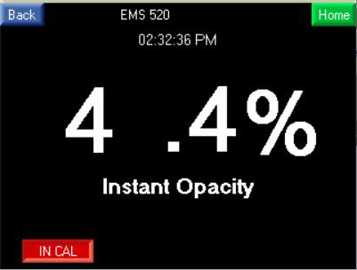
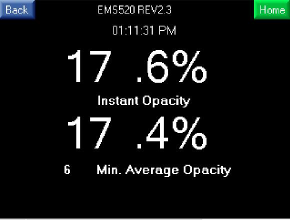
14 OPACITY DISPLAYS 13


15 DUST DISPLAYS 0 14


16 CALIBRATION PAGE Touch the Cal Icon on the home page. Initiate a Z/S check by pressing the Green Manual Cal Initiate button (It will turn Yellow). The zero is 3 minutes and span is 3 minutes long for calibration cycle of 6 minutes. The Right column will show In Zero and at about 30 seconds will update the Green Pass or the Red Fail icon. The values are the entered at set up in the tech screen under Zero cal value, Span Cal Value". If these values are within +/- 2% Opacity the green Pass will be shown, If it is not it will show Red Fail and trigger the fault system. Fail will remain in memory until after the values are corrected and another cal is initiated. The current opacity and window dust is displayed below for your convenience. The system will automatically return to monitoring the process at the Average point from cal start. You will know this because the Manual Cal Initiate icon will return to Green. It is not necessary to stay in this screen after initiation and recommended to return to the screen normally displayed. NOTE: Should a fail display Environmental Monitor Service, Inc. is available to assist you, call our service department at (203) ext 14 or fax (203) or techsupport@emsct.com 15

17 SETTINGS PAGE From the Home screen Touch the Settings icon to get to this page. For Operator setup press the button, and enter the default password 1111 when indicated and press return arrow. For Tech setup press the button, and enter the default password 1234 when indicated and press return arrow. 16


18 OPERATOR SETUP All raised buttons can be touched and values changed. All flat buttons are read only. The opacity and mg alarms can be turned on or off by touching the appropriate alarm ON/OFF button. TECH SETUP AND BACKUP/RESTORE All raised buttons can be touched and values changed. Instructions are on the bottom of the screen when required. All flat buttons are read only. 17

19 SD Card Screen If not already there, Enter SD Password: 123 Backup: After startup is complete and all controller changes are made, enter a new file name with 8 characters and/or numbers only, no more, no less. Touch Backup PLC -> SD System backup all changes to the S.D. card. Restore: to restore put the name of your backup and touch Restore SD -> PLC. This will take several minutes to complete the backup. 18


20 Tech Setup Screen 2 All raised buttons can be touched and values changed. Instructions are on the bottom of the screen when required. All flat buttons are read only. Cal time is in 24hr clock format. Note: If in internal the clock will control the cycle. While in external the internal clock is disabled and only an external input will activate the cycle. All raised buttons can be touched and values changed. Instructions are on the bottom of the screen when required. All flat buttons are read only. 19


21 SET LOCAL TIME AND DATE To set to local time touch and hold any part of the Yellow back ground until Info Mode appears. 1. Touch Enter Info Mode at Enter Password page, enter 1111, and touch the return button. 2. Touch Time & Date button. 3. Enter the Date dd/mm/yy. 4. Enter the time in 24hr hh:mm: ss. Press ESC until Tech page returns. 20


22 All raised buttons can be touched and values changed. All flat buttons are read only. All raised buttons can be touched and values changed. Instructions are on the bottom of the screen when required. All flat buttons are read only. 21
. The tech can reset to default value by holding the reset button for 3 seconds. CRITICALLY IMPORTANT!")
23 CHANGE PASSWORDS Only the tech can change passwords the default for Operator is (1111) and for Tech (1234). To change passwords touch raised button and enter new password (up to 8 numbers are provided). The tech can reset to default value by holding the reset button for 3 seconds. CRITICALLY IMPORTANT! THE TECH (GATEKEEPER) OF THE CONTROL UNIT AT HIS DISCRETIAN CAN CHANGE BOTH PASSWORDS; HOWEVER IT IS CRITICAL THAT THE PASSWORD IS SECURED AGAINST LOSS. IF GATEKEEPER S PASSWORD IS LOST CONTACT THE FACTORY FOR PROCEDDURE TO RESET TO DEFAULT SETTINGS.THIS PROCEEDURE IS IN PLACE TO PROTECT THE INTEGRITY OF THE DATA COLLECTED AND THE OPERATION OF THE UNIT. 22


24 DIAGNOSTICS PAGE These pages are intended to be used by EMS Factory trained technicians and detailed explanation of their use is not in the scope of this manual. Touching the Controls button for control page requires the tech password. WARNING: pre-set returns all selections to default. Do not use unless instructed by EMS service engineer. Touch the Relays button in the sub menu for conditions of the relays to be checked, relay # is de-energized if gray energized if green. Touch the Digital in the sub menu button, or the right arrow for checking input conditions. Inputs are gray if NO input, RED if input is active. 23

25 FAULT PAGE If one or more faults are detected a FAULT button will appear on any display screen. Touch it and the fault screen will be displayed indicating the fault(s). Press in the Acknowledge button will de-energize the fault relay. If after time set in tech screen 4, the relay will energize if all faults have not been repaired. 24


26 ALARM PAGE The count reset clears the alarm count column. Alarm Relay Auto/Manual operation default is Auto (automatic). To change it selected in the operator control page. See Appendix B for alarm relay matrix. Auto/Manual select. 25
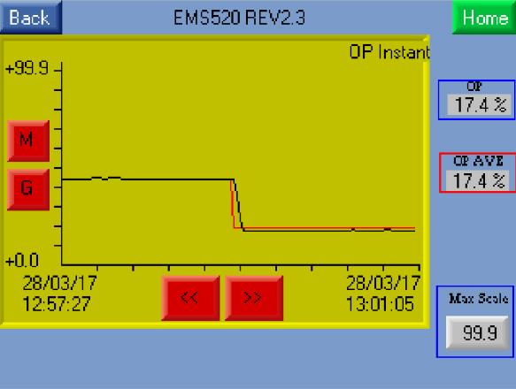
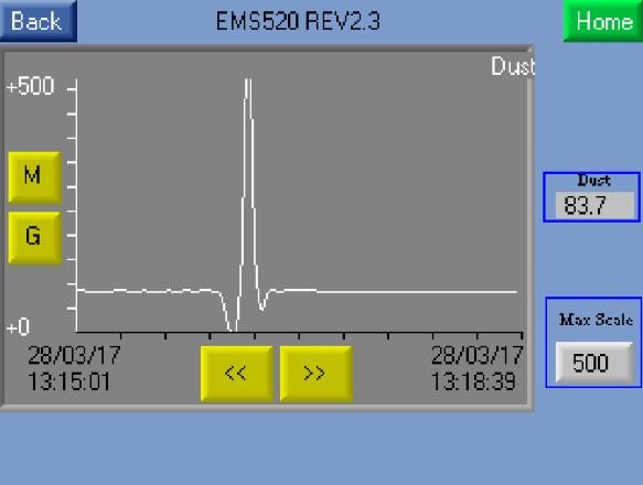
27 DISPLAY PAGE Max Scale in each trend screen can be set for: Opacity -5 to 99.9, Dust

28 ABOUT PAGE About page displays the basic setup information. 27
29 SECTION 4 MODBUS MODBUS ADDRESS INFORMATION MB = Modbus Poll Read Discrete inputs ( ) MI = Modbus Poll Read Holding ( ) Read: Address: Example: Instantaneous opacity MI = 18.1% Average opacity % MI = 18.2% Instantaneous O.D. Display MI 232 (0-2.0) Instantaneous Mg MI 233 (0-2000) Window dust MI % OPLR Calculated MI 245 OPLR Opacity Last MI 246 For process control. In cal last value going in is held Read; Common fault individual blocks: Mg High alarm MB 235 Zero, not cal = 0, in cal =0 Opacity high alarm MB 236 Zero, not cal = 0, in cal =1 Opacity Early warning alarm MB 239 No alarm =0. Alarm =1 Mg Early warning alarm MB 240 Span, not cal = 0, in cal =1 In maintenance MB 241 In Maint. =0, Not In Maint. =1 SM Power status MB 242 Lost power to SM=0, Power OK =1 T2 Signal lost/low MB 243 Signal OK =0, Lost signal =1 Negative opacity MB 244 Positive opacity =0, Negative Opacity =1 Zero Cal Fail MB 245 Fail =1, Not fail =0 Span Cal Fail MB 246 Fail =1, Not fail =0 No Air flow (Modbus only) MB 247 OK =0, Not OK =1 Zero DAS and/or In Cal MB 248 Off = 0, On = 1 Write: Remote Cal. Initiate MB 249 Initiate cal =1 28
30 RS/485-MODBUS COMMUNICATIONS AND CONNECTION TO CUSTOMER DATA AQUSITION SYSTEMS Port 2, 6-pin R J25 connector Pin 1 (+), Pin 6 (-). RS-485 cabling may be up to 2000 feet in length. Belden P/N 3106A cable is recommended. Note: Cable drawing and pin out at the end of drawing section. If not specified in the original order default is as follows. NOTE: The following communication parameters cannot be changed in the field the controller must be returned to the factory. Baud Rate: 9600 Data Bits: 8 Parity: None Flow Ctrl: None Timeout: 0.2 seconds. SECTION 5 OPTIONAL SNAP-IN OPTIONAL SNAP-IN ALARM RELAY/IO WIRING Refer to EMS520_Vol,2 Electrical wiring OPTIONAL SNAP-IN ANALOG OUTPUT CONNECTIONS Refer to EMS520_Vol,2 Electrical wiring 29
31 SECTION 10 ALARM MATRIX It is recommended to print drawings with the highest print quality. Auto alarm reset without pushing rest button. High mg Alarm 011: 0=open, 1= closed High Op AL 012: 0=open, 1= closed mg/op Alarm silence O13: 0= open, 1= closed E.W. Op AL O15: 0= open, 1= closed E.W. mg Alarm O16: 0= open, 1= closed Start 0%, use test value above High set points > Hi Mg 150mg set point after delay satisfied (AL) > Hi Op 20% set point after delay satisfied (AL) Return to 0% Auto alarm reset pushing rest button before returning to zero. Start 0%, use test value above High set points > set point after delays satisfied (AL) > set point EW, Reset button pushed > set point Process Alarm, Reset button pushed Return to 0% Manual alarm reset after returning to zero. Start 0%, use test value above High set points > set point after delays satisfied (AL) Return to 0% Process Alarm reset button pushed EW reset button pushed Manual alarm reset before, than after returning to zero. Start 0%, use test value above High set points > set point after delay satisfied (AL) Process Alarm reset button pushed EW reset button pushed Return to 0% Process Alarm reset button pushed EW reset button pushed
EMS510 PS-1 COMPLIANT OPACITY/DUST MONITOR
 EMS510 PS-1 COMPLIANT OPACITY/DUST MONITOR The EMS510 provides continuous, low maintenance, precision measurement of Opacity and Dust (mg/m3). It is designed for monitoring visible smoke in the exhaust
Instruction Manual Rev 2.0. OPM3000 Opacity/Dust Density Monitor Installation and Operation Manual Rev 2.0
 Instruction Manual Rev 2.0 OPM3000 Opacity/Dust Density Monitor Installation and Operation Manual Rev 2.0 Table of Contents TECHNICAL SUPPORT HOTLINE...4 SECTION 1 - SYSTEM DESCRIPTION AND SPECIFICATIONS...6
OPM4001 Opacity/Dust Density Monitor Installation and Operation Manual
 OPM4001 Opacity/Dust Density Monitor Installation and Operation Manual Page 1 Table of Content Contents TECHNICAL SUPPORT HOTLINE...4 SECTION 1 SYSTEM DESCRIPTION...6 TRANSMISSOMETER /RETRO REFLECTOR...
Instruction Manual IM , Rev 2.0 November 2008 OPM Opacity/Dust Density Monitor.
 Instruction Manual OPM 3000 Opacity/Dust Density Monitor http://www.raihome.com HIGHLIGHTS OF CHANGES Page Page 1-6 Page 1-7 Page 2-1 Page 2-5 Page 2-9 Page 2-11 Summary Effective November 12, 2008 Rev
EMS510 Electrical Wiring Guide Volume 2, Rev 1.4
 EMS510 Electrical Wiring Guide Volume 2, Rev 1.4 Prepared by Michael L. Kominske Environmental Monitor Service Inc. PO Box 4340 Yalesville, CT 06492 Phone 203.935.0102 Fax 203.634.6663 Email: sales@emsct.com
Instruction Manual IM , Rev 1.1 January 2007 OPM Opacity/Dust Density Monitor.
 Instruction Manual OPM 3000 Opacity/Dust Density Monitor http://www.raihome.com HIGHLIGHTS OF CHANGES Page Summary Effective August 31, 2006 Rev 1.0 General Revised and removed the figures from Section
OPAL 200S SERIES OPERATOR AND SERVICE MANUAL OPAL 200 OPACITY & DUST MONITORING SYSTEM OPERATION AND SERVICE MANUAL. Feb-09 1 Revision 1 V46
 OPAL 200 OPACITY & DUST MONITORING SYSTEM OPERATION AND SERVICE MANUAL Feb-09 1 Revision 1 V46 Product Registration 3 Service Support Procedures 4 SECTION 1 OPAL 200 OPTICAL SYSTEM. 5 1.1 General Description
ModSync Sequencing System Installation & Operation Manual. For use with Fulton Steam Boilers.
 ModSync Sequencing System Installation & Operation Manual For use with Fulton Steam Boilers. Revision 3.0 8/21/2008 - 2 - Table of Contents Introduction Page 4 Features Page 4 Sequence of Operation Page
Model DT109D Opacity Measurement System
 Opacity Measurement System Datatest Industries P.O. Box 801 Belle Mead, NJ 08502 Revision 0.0 Page 1 of 46 Table of Contents TABLE OF CONTENTS... 2 SECTION 1 - OPACITY MEASUREMENT SYSTEM OVERVIEW... 4
4500MkIII COMPLIANCE OPACITY AND DUST MONITORING QAL 1 PS-1 ASTM D6216 PROCEDURE 3 PS-11 QUALITY CUSTOMER SOLUTIONS
 4500MkIII COMPLIANCE OPACITY AND DUST MONITORING i QAL 1 PS-1 ASTM D6216 PROCEDURE 3 PS-11 QUALITY CUSTOMER SOLUTIONS 4500MkIII AMETEK LAND HAS BEEN MANUFACTURING PRECISION MEASURING EQUIPMENT SINCE 1947.
GASGUARDIAN Channel Controller OPERATING & INSTALLATION MANUAL
 GASGUARDIAN 2 3 2-Channel Controller OPERATING & INSTALLATION MANUAL GasGuardian 2 3 Operating and Installation Manual Table of Contents General description.... 3 Installation. 3 Locating the GasGuardian-2..
Halton SAFE / 7.14 user guide and installation instructions
 Halton SAFE / 7.14 user guide and installation instructions VERIFIED SOLUTIONS BY H A LTO N Enabling Wellbeing Table of contents 1 System description 3 2 User Accounts 4 3 Main menu 7 3.1 Main menu - Change
GG-2 2-CHANNEL GAS DETECTION CONTROL PANEL. Installation and Operation Manual
 GG-2 2-CHANNEL GAS DETECTION CONTROL PANEL Installation and Operation Manual 2 GG-2 Warning Use this product only in the manner described in this manual. If the equipment is used in a manner not specified
Replaceable LED modules. Sleep or unattended mode. Auto-silence and auto-acknowledge
 Replaceable LED modules 11 Alarm Sequences as per ISA-18.1 standard Each channel/window fully field programmable RS232 or RS485 MODBUS-RTU communication Repeat relay for each window and multifunction relays
Carbon Monoxide Transmitter
 Introduction The CO Transmitter uses an electrochemical sensor to monitor the carbon monoxide level and outputs a field-selectable 4-20 ma or voltage signal. The voltage signal may also be set to 0-5 or
Tri-Stack Smart System
 Tri-Stack Smart System TM Notes & Warnings - The protection provided by this equipment may be impaired if it is not used in the manner specified herein. - Ensure all wiring meets applicable national and
PROCESS & TEMPERATURE UNIVERSAL INPUT DIGITAL METERS
 PROCESS & TEMPERATURE UNIVERSAL INPUT DIGITAL METERS NOVA PD56 Series Thermocouple, RTD, & Process Inputs Universal Power Supply 1-24 VAC Up to 3 Alarm Relays Retransmitting 4-2 ma Output Input Max/Min
Process & TeMPerATUre UniversAl input DigiTAl MeTers
 Process & TeMPerATUre UniversAl input DigiTAl MeTers nova PD56 series Thermocouple, rtd, & Process inputs Universal Power supply 1-24 va c Up to 3 Alarm relays retransmitting 4-2 ma output input Max/Min
Analog Room Pressure Monitor RPC Series
 Description The Room Pressure Monitor is used to measure differential pressure in the range of 0.125 to 1"wc or 30 to 250 Pa. It combines precision high sensitivity silicon sensing capabilities and the
SCAN200E USER S MANUAL
 SCAN200E USER S MANUAL Code No. 2071 1052 rev. 1.4 Code No. 2071 1052 Rev. 1.4 Page 2/16 SCAN200E User s Manual Foreword This manual is for SCAN200E Controller running software version 2.03 or later. We
IMPORTANT. PLEASE NOTE: The infrared beam path MUST be kept clear of obstructions at all times!
 USER GUIDE English IMPORTANT PLEASE NOTE: The infrared beam path MUST be kept clear of obstructions at all times! Failure to comply may result in the Detector initiating a Fire or Fault signal. Contents
INSTALLATION INSTRUCTIONS
 TT-1343 5/06b INSTALLATION INSTRUCTIONS Original Issue Date: 8/03 Model: Automatic Transfer Switches Equipped with Series 1000 Programmable Controller Market: ATS Subject: Remote Annunciator Kits GM28938-KP1,
Laptop / PC Programming Manual
 Laptop / PC Programming Manual Doc. # Fire PC Program rev B 01.07 This Document is property of Evax Systems, Inc. The Evax Fire Solutions Programmer Components 2 1.0 System Setup 4 1.1 Interface Setup
Mark 25 Ultrapure Water Conductivity Analyzer
 Martek Instruments, Inc. Mark 25 Ultrapure Water Conductivity Analyzer Instruction Manual WARRANTY POLICY Unless otherwise stated, MARTEK INSTRUMENTS, INC. warrants this equipment to be free from defects
1. Quick start-up guide
 1. Quick start-up guide This quick guide leads the way to install, start-up and configure necessary parameters in the normal cases. 1. PREPARING INSTALLATION Install fiber optic cable inside conduit. This
GLD-30 Gas Leak Detector
 GLD-30 Gas Leak Detector Installation, Operation & Maintenance General: The Archer Instruments GLD-30 is an ambient air monitor, used to detect the presence of a target gas (or gases) and to alert operators
AquaLynx 200 ADX. Monitoring and Control System. Background. Operation
 AquaLynx 200 ADX Monitoring and Control System The RODI Systems AquaLynx 200 ADX is a unique monitoring system for water treatment applications. The AquaLynx 200 ADX offers a dependable yet affordable
RPM1600 Series Room Pressure Monitors
 RPM1600 Series Room Pressure Monitors Technical Bulletin LB-RPM1611-0, LB--0 Code No. LIT-12012228 Issued October 2017 Refer to the QuickLIT website for the most up-to-date version of this document. How
Toxic and Explosive Smart Gas Monitor PN / Installation and User Manual
 Toxic and Explosive Smart Gas Monitor PN 151022/151023 Installation and User Manual Quest Controls, Inc. 208 9 th Street Dr. West Palmetto, FL 34221 www.questcontrols.com Phone: (941) 729-4799 Fax: (941)
Lift Station Level Controller
 Lift Station Level Controller Installation and Operation Manual 1 California Motor Controls, Inc. Benicia, CA Table of Contents 1. Features Product Overview... 4-6 Access Security... 7 Optional Features...
PowerLogic ION Setup Meter Configuration Software Configuration Guide
 PowerLogic ION Setup Meter Configuration Software Configuration Guide 70002-0293-03 12/2010 Conventions Used in this Manual This section describes the symbols and terminology used in this guide. Symbols
FIRERAY 5000 range USER GUIDE
 FIRERAY 5000 range USER GUIDE 0044-003-04 IMPORTANT PLEASE NOTE: The beam path MUST be kept clear of obstructions at all times! Failure to comply may result in the Detector initiating a Fire or Fault signal.
Infrared Temperature Sensor
 Infrared Temperature Sensor With High Speed Sensor, Small Measured Spot and Continuous LED Sighting OS-PC Series U High Speed Cube Sensor with Optional Touch Screen Display U Response Time 0.001 Seconds
NGC-40 PANEL MOUNTED ADVANCED MODULAR HEAT-TRACING CONTROL SYSTEM HTC HTC3
 NGC-40 PANEL MOUNTED ADVANCED MODULAR HEAT-TRACING CONTROL SYSTEM Local configuration and monitoring with Raychem Touch 1500 touch screen display PRODUCT OVERVIEW The Raychem NGC-40 is a multipoint electronic
Table of Contents 1. OVERVIEW SYSTEM LAYOUT SPECIFICATIONS FUNCTION... 11
 Table of Contents 1. OVERVIEW... 3 2. SYSTEM LAYOUT... 4 3. SPECIFICATIONS... 8 3.1 SYSTEM COMPONENTS...9 3.2 PLC INPUTS AND OUTPUTS...9 3.3 FUNCTION KEYS...10 3.4 DEFAULT SET POINTS AND TIMERS...10 4.
SCC Inc. Master Panel. Specifications. Document No. TS 2010 February 11, Product Description. Sample Specification
 February 11, 2019 Master Panel Product Description The Master Panel shall provide lead/lag control and time based, automatic rotation of up to eight (8) boilers, when used in conjunction with LMV3 or LMV5
SAMPLE SPECIFICATIONS CONTINUOUS MONITORING SYSTEM (Insitu)
") PART 1 - GENERAL A. RELATED DOCUMENTS SAMPLE SPECIFICATIONS CONTINUOUS MONITORING SYSTEM (Insitu) Federal, State, and local requirements as applicable. Attached Permit Attached drawings B. SUMMARY 1. Provide
PART 1 - GENERAL A. RELATED DOCUMENTS SAMPLE SPECIFICATIONS CONTINUOUS MONITORING SYSTEM (Insitu) Federal, State, and local requirements as applicable. Attached Permit Attached drawings B. SUMMARY 1. Provide
Nitrogen Dioxide (NO2) Single-Point Gas Detection System
 Single-Point Gas Detection System") Nitrogen Dioxide (NO) Single-Point Gas Detection System DESCRIPTION Wall-mounted gas monitor with built-in nitrogen dioxide (NO)/diesel fume gas sensor, accepts one analog remote device such as a secondary
Nitrogen Dioxide (NO) Single-Point Gas Detection System DESCRIPTION Wall-mounted gas monitor with built-in nitrogen dioxide (NO)/diesel fume gas sensor, accepts one analog remote device such as a secondary
Operating & Maintenance Manual. Alert-4 Ethernet LCD Master Alarm
 Operating & Maintenance Manual Alert-4 Ethernet LCD Master Alarm w w w. a m i c o. c o m Contents User Responsibility 4 Introduction 4 Features 5 Description of the Alarm 5 Shipment Details 5 The Alarm
Intelligent Single Loop Fire Alarm Control Panel
 Intelligent Single Loop Fire Alarm Control Panel The CAX-CTL-1L Intelligent Single Loop Fire Alarm Control Panel is a member of the industry leading Axis AX Series Intelligent Fre Alarm Control Panels
Gas Detection System TOX ALARM DG2000-Garage
 Gas Detection System TOX ALARM DG2000-Garage Gas Detection System 32 independent programmable channels 2 programmable alarm levels for each gas = up to 6 for each channel LCD alphanumeric display of gas
TYPE CM-2201 NELSON SINGLE POINT CIRCUIT MANAGEMENT SYSTEM
 2 Line, 16 Characters/row LCD Display Temperature Input Range -50 C to +500 C -58 F to + 932 F Enclosure NEMA Type 4X Current Rating 30A max (resistive load only) Ambient Temperature -40 C to + 40 C -40
Intelligent 2 & 4 Loop Fire Alarm Control Panels
 Intelligent 2 & 4 Loop Fire Alarm Control Panels Advanced has combined the latest technology with many years of fire experience, to create the Axis AX Series Intelligent Fire Alarm Control Panels. The
READ AND SAVE THESE INSTRUCTIONS
 XXXXXXX-0 EN 1904 READ AND SAVE THESE INSTRUCTIONS BASIC-PLC CONTROLLER MANUAL For all Condair desiccant dryer with equipped with Basic- PLC valid from version: PLC-35/PLC-45 18.04.03 Dehumidification
SECTION Process and Immersion Turbidity and Total Suspended Solids Sensor
 SECTION 40 75 53 Process and Immersion Turbidity and Total Suspended Solids Sensor PART 1 General 1.01 SUMMARY A. Requirements for a digital sensor for process turbidity or Total Suspended Solids (TSS)
NGC-40 PANEL MOUNTED ADVANCED MODULAR HEAT-TRACING CONTROL SYSTEM HTC HTC3 PRODUCT OVERVIEW
 NGC-40 PANEL MOUNTED ADVANCED MODULAR HEAT-TRACING CONTROL SYSTEM Local configuration and monitoring with Raychem Touch 1500 touch screen display PRODUCT OVERVIEW The nvent RAYCHEM NGC-40 is a multipoint
Two-Channel Gas Controller
 Two-Channel Gas Controller Specifications subject to change without notice. USA 09 Page of DESCRIPTION Highly configurable, UL 0 performance-tested and -certified, and wall-mounted gas monitor; continuously
Ethernet General Purpose
 Ethernet General Purpose Technical Manual Revision 1.03 8 November 2013 Pakton Technologies IO PAE224 Ethernet GPIO Manual.docx Page 1 of 22 Revision 1.03 Last updated 8/11/2013 Table of Contents INTRODUCTION...3
Revision November 2013 JVA Technologies. Ethernet General Purpose IO Technical Manual
 Revision 1.03 8 November 2013 JVA Technologies Ethernet General Purpose IO Technical Manual www.jva-fence.com.au Table of Contents INTRODUCTION...3 Scope and Purpose...3 Glossary...3 SPECIFICATIONS...4
Operations Manual TS400. Test Station for G450/G460 Gas Detector
 TS400 Test Station for G450/G460 Gas Detector Operations Manual 1194 Oak Valley Dr, Ste 20, Ann Arbor MI 48108 USA (800) 959-0329 (734) 769-0573 www.goodforgas.com GfG Products for Increased Safety Congratulations
CONTROL UNIT: REFERENCE MANUAL
 CONTROL UNIT: REFERENCE MANUAL 1 THE DISPLAY AND REVIEW SCREENS...3 1.1 The Single Bar-graph Display...4 1.2 The View Multiple Devices Display...5 1.2.1 Multiple Bar-graph Display...5 1.2.2 Multiple Device
CONsOlIDATOR 4 & 8. MulTI- C h ANNEl CONTROllERs. ConsoliDator 4 Model PD940 ConsoliDator 4 Features. ConsoliDator 8 Features.
 CONsOlIDATOR 4 & 8 MulTI- C h ANNEl CONTROllERs ConsoliDator 4 Model PD940 ConsoliDator 4 Features Four 4-20 Four 4-20 Outputs ConsoliDator 8 Features Eight 4-20 Two 4-20 Outputs Common Features Four Pulse
Operation Manual Fighter ProVision Software. Version: 0.0 Revision: 1
 Operation Manual Fighter ProVision Software Version: 0.0 Revision: 1 TABLE OF CONTENTS 1. Introduction 5 2. Software Installation 5 3. PC Users 6 3.1 Introduction 6 3.2 Default Code 6 3.3 Edit PC User
SM3000 Videographic Recorder. User Guide. Modbus (RTU) Communications Option
 Communications Option") SM3000 Videographic Recorder User Guide (RTU) Communications Option ABB The Company We are an established world force in the design and manufacture of instrumentation for industrial process control, flow
SM3000 Videographic Recorder User Guide (RTU) Communications Option ABB The Company We are an established world force in the design and manufacture of instrumentation for industrial process control, flow
INSTALLATION & USER MANUAL
 INSTALLATION & USER MANUAL HC Digital Automatic Humidistat (Y3760) CONTROLS 506808-01 3/2016 Supersedes 6/2011 picture goes here THIS MANUAL MUST BE LEFT WITH THE HOMEOWNER FOR FUTURE REFERENCE NOTICE
Turbimax CUE21 / CUE22
 Technical Information Turbimax CUE21 / CUE22 Turbidimeter for on-line measurement Application On-line continuous monitoring of clean water: Drinking water Treated process water Your benefits Versions with
Across-the-Line SERIES MP300 Combined Manual and Automatic
 Across-the-Line SERIES MP300 Combined Manual and Automatic Metron Fire Pump Controllers conform to the latest requirements of National Fire Protection Association s Standard for Centrifugal Fire Pumps
THX-DL Data Logger USER & INSTALLATION MANUAL V
 THX-DL Data Logger USER & INSTALLATION MANUAL V1.2012 www.thermomax-refrigeration.com Contents PRESENTATION Summary of Features 2 INSTALLATION Safety Precautions 4 THX Unit 4 Sensors 4 Alarm Relay 4 Power
AH3000 SERIES 180MM CHART PEN TYPE HYBRID RECORDER
 AH3000 SERIES 180MM CHART PEN TYPE HYBRID RECORDER MODEL AH3 7 P - - A AH3000 series conforming to CE, UL and CSA are 180mm pen type hybrid recorders with a simultaneous display of multi-channel data,
OPERATING MANUAL. EchoTherm PROGRAMMABLE DIGITAL CHILLING INCUBATOR MODELS IN35, IN45 and IN55-12VDC. DOCUMENT NUMBER IN35-03 Revised 15 May 2015
 OPERATING MANUAL EchoTherm PROGRAMMABLE DIGITAL CHILLING INCUBATOR MODELS IN35, IN45 and IN55-12VDC DOCUMENT NUMBER IN35-03 Revised 15 May 2015 TORREY PINES SCIENTIFIC, INC. 2713 Loker Ave. West Carlsbad,
S304 and S305 Dust Emission Monitors. User Manual. Distributor
 S304 and S305 Dust Emission Monitors User Manual Distributor Version 6.4 30/5/2012 Table of Contents 1. INTRODUCTION... 3 1.1 Safety... 3 1.2 Product overview... 4 1.3 Principle of operation... 4 2. INSTALLATION...
THEORY OR OPERATION 2 SENSOR UNIT - MECHANICAL 6 SENSOR UNIT - ELECTRICAL 8 CONTROL UNIT - MECHANICAL 9 CONTROL UNIT - ELECTRICAL 9 OPTIONS 11
 Table of Contents INTRODUCTION 1 THEORY OR OPERATION 2 DESCRIPTION 5 SENSOR UNIT - MECHANICAL 6 SENSOR UNIT - ELECTRICAL 8 CONTROL UNIT - MECHANICAL 9 CONTROL UNIT - ELECTRICAL 9 SPECIFICATIONS 10 OPTIONS
EOS INTERFACE GUIDE AND POINTS LIST For EOS BTCII Firmware Version J1239D-570 and newer
 Installation and interface must be performed by a qualified controls technician. IMPORTANT: THIS MANUAL CONTAINS INFORMATION REQUIRED FOR INSTALLATION, INTERFACE AND CONFIGURATION OF THIS EQUIPMENT. READ
RS485 MODBUS Module 8AI
 Version 1.4 15/04/2013 Manufactured for Thank you for choosing our product. This manual will help you with proper support and proper operation of the device. The information contained in this manual have
USER MANUAL FOR OPERATING SYSTEM
 P2262 ALARM PANEL USER MANUAL FOR OPERATING SYSTEM 21765-07 September 1999 Associated Controls (Aust) PTY. LTD. 29 Smith Street, Hillsdale, NSW, 2036. PH (02) 9311 3255, FAX (02) 9311 3779 Page 1 of 177
Oxygen (O2) Single-Point Gas Detection System
 Single-Point Gas Detection System") Oxygen (O) Single-Point Gas Detection System DESCRIPTION Wall-mounted gas monitor with built-in oxygen (O) sensor, accepts one analog remote device such as a secondary gas sensor, temperature or humidity
Oxygen (O) Single-Point Gas Detection System DESCRIPTION Wall-mounted gas monitor with built-in oxygen (O) sensor, accepts one analog remote device such as a secondary gas sensor, temperature or humidity
ACTIVE INFRARED BARRIER
 Although PROTECH provides high security indoor intrusion sensors for the military and government markets, our specialty is outdoor protection. Since we first introduced our PIRAMID outdoor dual technology
IMR 5000 Operating Manual S/N: SAMPLE For information only! IMR Environmental Equipment Inc.
 IMR 5000 Operating Manual S/N: For information only! IMR Environmental Equipment Inc. INTRODUCTION 3 SAFETY INSTRUCTIONS 3 SYSTEM DESCRIPTION - IMR 5000 GAS ANALYSIS SYSTEM 4 Function chart IMR 5000 -
Operations Manual TS400. Test Station for G450/G460 Gas Detector
 TS400 Test Station for G450/G460 Gas Detector Operations Manual 1194 Oak Valley Dr, Ste 20, Ann Arbor MI 48108 USA (800) 959-0329 (734) 769-0573 www.gfg-inc.com GfG Products for Increased Safety Congratulations
Laser Distance Sensor Type M Analog-Output
 Laser Distance Sensor Type M Analog-Output Operating Manual Version 2.3, May 2009 ELAG Elektronik AG l Stegackerstrasse 14 l CH-8409 Winterthur Contents 1. Safety 1.1 Laser safety 1.2 Electrical safety
Sintrol Snifter A2 EX. Manual. Version 1.2.3
 Sintrol Snifter A2 EX Manual Version 1.2.3 Table of Contents 1 INTRODUCTION... 3 1.1 Safety... 3 1.2 Product overview... 4 1.3 How does it work?... 4 2 INSTALLATION... 4 2.1 Selecting the installation
SUPREMATouch. Modular Fire & Gas Detection System
 SUPREMATouch Modular Fire & Gas Detection System Fire & Gas Detection Solutions MSA permanent gas detection systems are used throughout the world to protect plant and personnel from hazardous gases in
SLATE. Base Module INSTALLATION INSTRUCTIONS R8001A1001
 SLATE Base Module R8001A1001 INSTALLATION INSTRUCTIONS Scan for more information Application SLATE brings configurable safety and programmable logic together into one single platform. The platform can
CommStat 6. Controller for Redundant HVAC Systems PRODUCT DATA SHEET
 CommStat 6 Controller for Redundant HVAC Systems PRODUCT DATA SHEET General Description The CommStat 6 HVAC controller is designed for controlling up to six redundant air conditioners in an E-House or
AUTOMATION. Operator s Manual RST Series Web Enabled Input Module. Rev. A2, 1/12
 AUTOMATION P R O D U C T S GROUP, INC. Operator s Manual RST-5000 Series Web Enabled Input Module Rev. A2, 1/12 Tel: 1/888/525-7300 Fax: 1/435/753-7490 www.apgsensors.com E-mail: sales@apgsensors.com RST-5000
Variable Frequency Drive SERIES MP800 VFD
 Metron Fire Pump Controls and Accessories Variable Frequency Drive SERIES MP800 VFD Metron Fire Pump Controllers conform to the latest requirements of National Fire Protection Association s Standard for
ZXe INTELLIGENT MULTI PROTOCOL FIRE ALARM CONTROL PANEL
 ZXe INTELLIGENT MULTI PROTOCOL FIRE ALARM CONTROL PANEL PRODUCT Specification FEATURES Designed To Meet The Requirements Of EN54 Expandable From 1 To 5 Loops As Standard A Variety Of Networking Options
DS7400Xi Addressable Control/ Communicator
 DS7400Xi Addressable Control/ Communicator DS7400Xi DS7400Xi-EXP 110VAC operation 220VAC operation Remotely Programmable WDSRP (Windows Detection Systems Remote Programming Software), allows the systems
I/A Series 716C 1/16 DIN Temperature Controller
 Product Specifications I/A Series 716C 1/16 DIN Temperature Controller PSS 2C-1B5 A The Foxboro 716C is a powerful compact, 1/16 DIN, microprocessor-based temperature controller that offers a variety of
DENVER PUBLIC SCHOOLS DESIGN AND CONSTRUCTION STANDARDS This Standard is for guidance only. SECTION IBAS LIGHTING CONTROL
 PART 0 A/E INSTRUCTIONS 0.01 DESIGN REQUIREMENTS A. Minimum lighting control (base scope of work) shall include all corridors. The lighting in all the corridors shall be turned on (if not already on) if
DIMENS. MIN TYPICAL MAX A 71.0 (2.795) 71.0 (2.795) 71.8 (2.826) B 29.0 (1.141) 29.0 (1.141) 29.8 (1.173)
 71.0 (2.795) 71.8 (2.826) B 29.0 (1.141) 29.0 (1.141) 29.8 (1.173)") Evco S.p.A. Code 104K204E05 page 1/5 EVK204 Digital controller for ventilated refrigerating units, with HACCP and Energy Saving functions version 1.05 GB ENGLISH 1 PREPARATIONS 1.1 Important Please read
Evco S.p.A. Code 104K204E05 page 1/5 EVK204 Digital controller for ventilated refrigerating units, with HACCP and Energy Saving functions version 1.05 GB ENGLISH 1 PREPARATIONS 1.1 Important Please read
HIGH EFFICIENCY FIRETUBE CONDENSING GAS BOILER
 This manual must be left with owner and should be hung on or adjacent to the boiler for reference. US HIGH EFFICIENCY FIRETUBE CONDENSING GAS BOILER MODELS CHS-85 through CHS-399 APPENDIX A CONTROLLER
Guide Specification - MasterFormat 2017 Style SECTION FLOW INSTRUMENTS PART 2 PRODUCTS 2.1 SECTION INCLUDES 2.2 ACCEPTABLE MANUFACTURERS
 SECTION 230923.14 FLOW INSTRUMENTS Data contained in this guide specification may be placed in either of the following sections, depending on the specifics of the system design, or incorporated within
SUPREMATouch. Modular Fire & Gas Detection System
 SUPREMATouch Modular Fire & Gas Detection System Tel: +44 (0)8 9388 Email: info@ Fire & Gas Detection Solutions MSA permanent gas detection systems are used throughout the world to protect plant and personnel
MODEL 4200-IR-2 (Up to 2 Sensors) MODEL 4200-IR-4 (Up to 4 Sensors) MODEL 4200-IR-6 (Up to 6 Sensors)
 MODEL 4200-IR-4 (Up to 4 Sensors) MODEL 4200-IR-6 (Up to 6 Sensors)") MODEL 4200-IR-2 (Up to 2 Sensors) MODEL 4200-IR-4 (Up to 4 Sensors) MODEL 4200-IR-6 (Up to 6 Sensors) Refrigerant Monitor User Manual Technical Support Continental North America Toll Free 1-(800) 387-9487
MODEL 4200-IR-2 (Up to 2 Sensors) MODEL 4200-IR-4 (Up to 4 Sensors) MODEL 4200-IR-6 (Up to 6 Sensors) Refrigerant Monitor User Manual Technical Support Continental North America Toll Free 1-(800) 387-9487
21-light Remote Annunciator. Owner s Manual
 21-light Remote Annunciator Owner s Manual Annunciator Description... Inside Font Cover Detailed Specifications... 1 Environmental Specifications... 1 Power Supply Requirements... 1 Communication With
Soft Start Series MP700 Solid State, Reduced Voltage
 Metron Fire Pump Controls and Accessories Soft Start Series MP700 Solid State, Reduced Voltage Metron Fire Pump Controllers conform to the latest requirements of National Fire Protection Association s
RAEGuard 2 PID. User Guide
 RAEGuard 2 PID User Guide P/N: H-D03-4001-000 Rev M February 2018 Contents Section 1: RAEGuard 2 PID User s Guide 1 General Information... 6 2 General Specifications... 8 2.1 RAEGuard 2 PID Specifications...
General Purpose IO Technical Manual
 General Purpose IO Technical Manual Revision 1.06 8 November 2013 Pakton Technologies PAE222 GPIO Manual.docx Page 1 of 21 Revision 1.06 Last updated 8/11/2013 Table of Contents INTRODUCTION...3 Scope
MODEL 8144-RD CLOCK SELECTOR/DISTRIBUTION AMPLIFIER INSTRUCTION MANUAL. SPECTRACOM CORPORATION 95 Methodist Hill Drive, Suite 500 Rochester, NY 14623
 MODEL 8144-RD CLOCK SELECTOR/DISTRIBUTION AMPLIFIER INSTRUCTION MANUAL SPECTRACOM CORPORATION 95 Methodist Hill Drive, Suite 500 Rochester, NY 14623 PHONE 585-321-5800 FAX 585-321-5218 REVISIONS, IF ANY,
Adaptive CyCLO Technical and HMI User Guide. CyCLO User Guide. Version th December 2017 REV
 CyCLO User Guide Version 2.00 19 th December 2017 REV 2.00 1 Contents 1. Hardware... 3 1.1. Introduction... 3 1.2. Electrical Specification... 3 1.3. Board Overview... 4 1.4. Electrical Installation...
The ID51 & ID52 can be upgraded to 2 loops without the need to change back box. FEATURES. Intelligent Features
 990-052, Issue 6 20 March 2006 ID50 Series Single Loop Intelligent Fire Alarm Panels Section: Intelligent Fire Alarm Panels GENERAL The NOTIFIER ID50 series single loop intelligent fire alarm panels, has
Multiview Monitor / Controller
 FEATURES: Bright/sunlight readable 7.0 LCD touch screen. Displays large, easy to read values, set points, room status, modes and alarms Up to six fully configurable Icons including: Environmental points
Digi-Sense TC9000 Advanced PID and On/Off Temperature Controller with Thermocouple Input
 User Manual 99 Washington Street Melrose, MA 02176 Phone 781-665-1400 Toll Free 1-800-517-8431 Visit us at www.testequipmentdepot.com Digi-Sense TC9000 Advanced PID and On/Off Temperature Controller with
GA-180 Gas Detector. Operation and Maintenance Manual
 GA-180 Gas Detector Operation and Maintenance Manual The information contained in this manual was current at the time of printing. The most current versions of all Hydro Instruments manuals can be found
4/8/12/16 Channel Temperature Scanner with FREE Data Logging PC Software RS485
 Select Option Device Wise Device/Group HumiLog Y-Axis Text Show/Hide Ledgends MIN MAX Scale Y Max 08-05-2015 15:17:59 PV_C PV_RH Color default default Graph Refresh Interval 2 Set Interval PV Low Alarm
Dryer Moisture Systems Inc. Dryer Master M 2. Product Manual
 Dryer Moisture Systems Inc. Dryer Master M 2 Revision 1. January, 27 Revision 1.1 March, 27 Revision 1.2 June, 27 Revision 1.22 July, 27 Revision 1.22.1 January, 28 Revision 1.22.2 April, 28 Revision 1.23
Universal Gas Detector
 Universal Gas Detector Instruction Manual PureAire Monitoring Systems, Inc. 557 Capital Drive Lake Zurich, Illinois 60047 Phone: 847-726-6000 Fax: 847-726-6051 Toll-Free: 888-788-8050 pureairemonitoring.com
Public Safety DAS Annunciator Panel
 Public Safety DAS Annunciator Panel 120 VAC Models: 1221-A, 1221-B, 1221-C Revision D 91117 48 VDC Models: 1221-A-48, 1221-B-48, 1221-C-48 24 VDC Models: 1221A-24, 1221-B-24, 1221-C-24 CAUTION: (Read This
Beacon 200 Gas Monitor Operator s Manual. Part Number: RK Released: 6/6/08
 Beacon 200 Gas Monitor Operator s Manual Part Number: 71-2102RK Released: 6/6/08 Table of Contents Chapter 1: Introduction.................................................3 Overview.............................................................3