METHODOLOGY. Definitions. A Collaboration of U.S. NRC Office of Nuclear Regulatory Research (RES) & Electric Power Research Institute (EPRI)
|
|
|
- Meredith Banks
- 5 years ago
- Views:
Transcription

1 EPRI/NRC-RES RES FIRE PRA METHODOLOGY Fire Fundamentals: Definitions
2 What is a Fire? Fire is an exothermic chemical reaction involving i a fuel and oxygen in the air Requires presence of: - Material that can burn, the fuel - Oxygen (air) - Energy (initial ignition source) Ignition source can be a spark, short in an electrical device, etc. Fire PRA Workshop, 2011 Fire Fundamentals - Definitions Slide 2
3 What is a Fire? Fire Triangle Fuel Oxygen (Air) Energy (Initially ignition source) Fire PRA Workshop, 2011 Fire Fundamentals - Definitions Slide 3
4 Materials that May Burn Materials that can burn are generally categorized by: Ease of ignition (ignition temperature or flash point) Flammable materials (e.g., gasoline) Combustible materials (e.g., wood, high ignition temperature oils, and diesel fuel) State Solid (wood, electrical cable insulation) Liquid (diesel fuel) Gaseous (hydrogen) Fire PRA Workshop, 2011 Fire Fundamentals - Definitions Slide 4
5 Combustion Process Combustion process involves... An ignition source comes into contact and heats up the material Material vaporizes and mixes up with the oxygen in the air and ignites Exothermic reaction generates additional energy that heats the material, that vaporizes more, that reacts with the air, etc. Flame is the zone where chemical reaction is taking place Fire PRA Workshop, 2011 Fire Fundamentals - Definitions Slide 5


6 What is Fire? Spark Flammable mixture Heat flux Fire PRA Workshop, 2011 Fire Fundamentals - Definitions Oxygen in air Fuel gas Slide 6 Solid fuel
7 Flame Characteristics Flame characteristics Flame color depends on the material burning Most flames are visible to the naked eye Flame temperature can range from 1,500 o F to 3,500 o F For example... Laminar flames ~ 3,500 o F, e.g., a candle flame Turbulent flames ~ 1,500 o F, e.g., a fire place Fire PRA Workshop, 2011 Fire Fundamentals - Definitions Slide 7
8 Effects of a Fire A fire generates heat, smoke and combustion products Heat is the main adverse effect of concern in a nuclear power plant Heat generated by the fire is transferred by radiation and convection Products of combustion include soot and other species such as HCL, etc. Smoke and soot can adversely affect equipment Smoke can be a hindrance to plant operators Fire PRA Workshop, 2011 Fire Fundamentals - Definitions Slide 8
9 Fire Plume A fire plume... Draws fresh air from the surroundings A part of the air gets used in the flame Air drawn above the flames gets heated up The hot gases rise and envelope items above the fire with very hot gases Hot gases transfer the larger portion of the energy generated by a fire by convection Fire PRA Workshop, 2011 Fire Fundamentals - Definitions Slide 9
10 Radiative Heat of a Fire Radiative heat from a fire is emanated from the flame in all directions A part of the radiative heat evaporates the fuel to continue the combustion process Fire PRA Workshop, 2011 Fire Fundamentals - Definitions Slide 10
11 Flame Spread and Fire Propagation Flame spread is a series of ignitions that can lead to fire propagation to adjacent or nearby items Fire PRA Workshop, 2011 Fire Fundamentals - Definitions Slide 11
12 Definitions Pyrolisis Breakdown of the molecules of a solid material from exposure to heat into gaseous molecules that combust in the flame. Smoldering A slow combustion process without visible flames that occurs in a porous solid fuel (e.g., burning of charcoal brickets or wood in a fire pit). Generally occurs because of limited oxygen access to the burning surfaces. It can generate large quantity of carbon monoxide which is lethal if inhaled. Fire PRA Workshop, 2011 Fire Fundamentals - Definitions Slide 12
13 Definitions Spontaneous Ignition Ignition of a combustible or flammable material without an ignition source, which is generally caused by raising material temperature above its auto-ignition temperature. vs. Piloted Ignition Ignition of a combustible or flammable material in the presence of a pre-existing existing flame (the pilot flame) Piloted ignition generally occurs at a lower temperature than spontaneous ignition Fire PRA Workshop, 2011 Fire Fundamentals - Definitions Slide 13
14 Definitions Flame- A flame is the visible (light-emitting) part of a fire. It is caused by an exothermic reaction taking place in a thin zone where fuel vapors and oxygen in the air meet. Fire Plume - A fire plume is a buoyant column of hot air rising above the base of a fire Ceiling Jet When the fire plume hits the ceiling, the flowing gasses turn 90 and form a relatively thin layer of flowing gas just below the ceiling this is the ceiling jet Fire PRA Workshop, 2011 Fire Fundamentals - Definitions Slide 14
15 Definitions Hot Gas Layer As the fire progresses, the heated air and combustion products tend to collect in a layer between the ceiling and somewhere above the floor this is the HGL (sometimes called the smoke layer) vs. Lower or Cold Gas Layer The gasses that remain between the floor and the bottom of the HGL and that generally remain at near ambient temperatures The depth of the HGL (distance from the ceiling to the bottom of the HGL) will be determined largely by ventilation conditions (e.g., an open door, open window ) Fire PRA Workshop, 2011 Fire Fundamentals - Definitions Slide 15
16 Definitions Diffusion Flame The flame of a burning material (liquid or solid) where the combustion process occurs at the interface where vaporized fuel comes into contact with the oxygen in the air (e.g., flame on top of a candle or the wood in a fireplace.) vs. Pre-mixed Flame The flame of burning gaseous material that is mixed with air upstream of the flame (e.g., the flame of a gas range or gas fired furnace) Most of the fires we are concerned with involve diffusion flames Fire PRA Workshop, 2011 Fire Fundamentals - Definitions Slide 16
17 Definitions Laminar Flame A flame with laminar flow of gases (e.g. typical candle flame). vs. Turbulent Flame a flame with turbulent flow of gases (e.g., most flames bigger than a candle). Most flames greater than a few inches tall demonstrate turbulent (non-laminar) behavior because of increased gas velocities caused by increased heat. Fire PRA Workshop, 2011 Fire Fundamentals - Definitions Slide 17
18 Definitions Conduction Heat transfer between two adjacent stationary media through the interface between them (e.g., putting your hand on a cold surface) Convection Heat transfer between a moving fluid and a solid or liquid material (e.g., blowing over a hot food to cool it down) Radiation Heat transfer through open space via electromagnetic energy between two materials of different temperatures that are within line of sight of each other (e.g., infra-red radiation from a very hot material). Fire PRA Workshop, 2011 Fire Fundamentals - Definitions Slide 18
19 Definitions Some key fire characteristics Mass Loss Rate (Burning Rate) The rate of mass loss of a burning material in a fire. It is commonly expressed in terms of mass per unit area per unit time (e.g., 10 g per cm 2 per second). Heat Release Rate (HRR) The energy release per unit time from a combustible material (kw) Heat Flux Heat transferred expressed per unit time per unit area (kw/m 2 ). Its is a good measure of fire hazard. Fire PRA Workshop, 2011 Fire Fundamentals - Definitions Slide 19
20 Definitions Heat Release Rate Profile The heat release rate as a function of time. Example... Fire PRA Workshop, 2011 Fire Fundamentals - Definitions Slide 20
21 Definitions Fire in the Open A fire occurring in a large or unconfined space such that there is no feedback between the fire and the ambient environment vs. Compartment Fire (Enclosure Fire) A fire occurring in an enclosed space such that the fire impact its surroundings creating a feedback effect; e.g. The walls get hot and feed radiant energy back to the fire A HGL forms and feeds radiant energy back to the fire The HGL descends to the floor and reduces the oxygen available to the fire We tend to deal mainly with compartment fires. Fire PRA Workshop, 2011 Fire Fundamentals - Definitions Slide 21
22 Definitions Fuel Limited Fire A fire where the heat generated by the fire is limited it only by the surface burning rate of the material. vs. Oxygen Limited Fire A fire (typically inside a compartment or enclosure) where the heat release rate is limited by Oxygen availability Not enough air for fire to grow beyond a certain point We tend to deal primarily with fuel limited fires, but cabinet fires, for example, may be oxygen limited Fire PRA Workshop, 2011 Fire Fundamentals - Definitions Slide 22
23 Definitions Upper and Lower Flammability Limits Concentration of a flammable gas in air in a pre-mixed flame that can sustain combustion. If the mixture is close to lower flammability limit, it is too lean. If the mixture is close to the upper flammability limit, it is too fuel rich. Fire Modeling vs. Fire Analysis Tasks Fire modeling is the analytical process of estimating the behavior of a fire event in terms of the heat flux impinging material near the fire and behavior of those materials as a result of that. Fire PRA Workshop, 2011 Fire Fundamentals - Definitions Slide 23
24 Definitions Zone-of-Influence (ZOI) The area around a fire where radiative and convective heat transfer is sufficiently strong to damage equipment or cables and/or heatup other materials to the point of auto- ignition. Fire PRA Workshop, 2011 Fire Fundamentals - Definitions Slide 24
25 EPRI/NRC-RES FIRE PRA METHODOLOGY Fires in the Open and Fully Ventilated Fires
26 Recall: Fuel limited fires A fire event where heat generated from the fire is limited by the surface burning rate of the material. Sufficient air is always available for the fire. Generates hot gases and radiative heat Generally applies to fires in the open or fires in large compartments A nuclear power plant has lots of large compartments Fire PRA Workshop, 2011 Fire Fundamentals - Fires in the Open Slide 2
27 Heat Release Rate The heat release rate from a fire can be estimated using the following equation: Q m A H c m is the burning mass flux Hc is the heat of combustion (kj/kg) A is the burning area (m2) Energy Released Rate Fuel m q Fire PRA Workshop, 2011 Fire Fundamentals - Fires in the Open Slide 3
28 Heat Release Rate Can be estimated experimentally using oxygen consumption calorimeters Q m O H ( kj / kg 2 2 c O ) H c = 13.1 kj/kg O2 Fire PRA Workshop, 2011 Fire Fundamentals - Fires in the Open Slide 4


29 Flames Laminar Turbulent Fuel Oxygen Reaction Zone Fire PRA Workshop, 2011 Fire Fundamentals - Fires in the Open Slide 5
30 Ignition of Gases With a spark or small flame (pilot) present, ignition is based on whether h the gaseous fuel concentration is between the upper (rich) and lower (lean) flammability limits. The fuel-air (oxidizer) mixture is said to be flammable if a flame will propagate in this mixture. For no pilot present, a gaseous fuel in air can also ignite if the mixture is at or above the auto-ignition temperature. t The auto-ignition temperature is usually measured for a stoichiometric mixture in which no fuel and oxygen remain after the reaction. Fire PRA Workshop, 2011 Fire Fundamentals - Fires in the Open Slide 6
31 Ignition of Liquids For a liquid to ignite, it must first evaporate sufficiently to form a flammable mixture in the presence of a pilot. This occurs at a liquid temperature called a flash-point temperature. In general, this can be called the piloted ignition temperature and the term carries over to solids. The flash-point is the temperature at which the amount of liquid evaporated from the surface achieves the lower flammable limit. If no pilot is present, the mixture must be heated to the auto- ignitioni i temperature. Auto-ignition temperature of gases is above its boiling point. Fire PRA Workshop, 2011 Fire Fundamentals - Fires in the Open Slide 7
32 Ignition of Solids Solids do not vaporize like liquids when heated. They form gaseous decomposition compounds leaving behind possible char in a process called pyrolysis. At some point, the gases ignite by piloted ignition or auto-ignition. Typically, piloted ignition temperatures for solids range from 250 C (~480 F) to 450 C(~840 F). Auto-ignition temperatures can exceed 500 C (~930 F). For a given material, these temperatures are not constants and can change with the nature of heating. For practical purposes, a (piloted) ignition temperature (T ig ) may be treated as a property of a combustible solid. We shall consider thin (less than ~1 mm) and thick solids to have different time responses to ignition when exposed to impinging heat flux Fire PRA Workshop, 2011 Fire Fundamentals - Fires in the Open Slide 8
33 Ignition Evaporated fuel Hot Surface * Spark Radiant Heat Liquids Solids Fire PRA Workshop, 2011 Fire Fundamentals - Fires in the Open Slide 9
34 Flame Spread Motion of vaporization front at the ignition temperature for solids and liquids Cable tray z f Fire x p Fire PRA Workshop, 2011 Fire Fundamentals - Fires in the Open Slide 10
35 Typical Flame Spread Rates It is very difficult to compute flame spread rate because formulas are not completely l available, rates may not be steady, and fuel properties are not generally available. Nevertheless, we can estimate approximate magnitudes for spread rates based on the type of system. These estimates are listed below: Spread Rate (cm/s) Smoldering solids to 0.01 Lateral or downward spread on thick solids 0.1 Upward spread on thick solids 1.0 to 100. (0.022 to 2.2 mph) Horizontal spread on liquids 1.0 to 100. Premixed flames (gaseous) 10. to 100.(laminar) 10 5 (detonations) ti Fire PRA Workshop, 2011 Fire Fundamentals - Fires in the Open Slide 11
36 Zone of Influence Regions nearby the fire where damage is expected. For fires in the open: Flame Radiation Target q Target Convection inside the fire plume x Fire PRA Workshop, 2011 Fire Fundamentals - Fires in the Open Slide 12
37 Buoyant Flow Temperature re rise gives a decrease in density Potential energy converted into kinetic energy V Buoyant plume Unit volume at plume gas at density and temperature T Z Unit volume of air at density a and temperature T a D Fire PRA Workshop, 2011 Fire Fundamentals - Fires in the Open Slide 13
38 Turbulent Entrainment Entrainment is air drawn into the fire plume by upward movement of the buoyant plume Engulfment of air into the fire plume Eddies: fluctuating and rotating balls of fluid, large scale rolling-up fluid motion on the edge of the plume. Buoyant force Eddies Flame Fire PRA Workshop, 2011 Fire Fundamentals - Fires in the Open Slide 14


39 Turbulent Fire Plume Very low initial fuel velocity Entrainment and flame height controlled by buoyancy Fire PRA Workshop, 2011 Fire Fundamentals - Fires in the Open Slide 15


40 Fire Plume Temperature Along the Centerline Fire PRA Workshop, 2011 Fire Fundamentals - Fires in the Open Slide 16
41 Example Case - Zone-of-Influence Calculation Flame Height and Plume Temperature 1 f f r T T Q 2 pl amb 5 1. D H p Fe L f 02 Heskdestad's Flame Height Correlation Input D - Fire diameter [m] 0.6 Q f - HRR [kw] 250 Result L - Flame height [m] 1.5 k Q 2 zo 0.083Q 5 f 1. 02D z 2 5 Heskestad's Plume Temperature Correlation Input T amb - Ambient temperature [C] 20 Q f - HRR [kw] 250 F e - Fire elevation [m] 0 H p - Target Elevation [m] 3.7 z 0 - Fire Diameter [m] 1 o 5 3 Result T pl - Plume Temp [C] 328 Fire PRA Workshop, 2011 Fire Fundamentals - Fires in the Open Slide 17
42 Example Case - Zone-of-Influence Calculation Radiation Heat Flux Flame Radiation: Point Source Model q irr Q f f 4 R r 2 Input Parameters: Q f : Fire heat release rate (kw) R: Distance from flames (m) X r : Radiation fraction of the heat release rate (FIVE recommends 0.4) D: Fire diameter (m) Fire PRA Workshop, 2011 Fire Fundamentals - Fires in the Open Slide 18
43 Example Case - Zone-of-Influence Calculation Radiation Heat Flux q irr Q f 4 R r 2 Point Source Flame Radiation Model Inputs Fire heat release rate [kw] 317 Radiation fraction 0.40 Distance from flames [m] 1.5 Results Heat flux [kw/m2] 4.5 Fire PRA Workshop, 2011 Fire Fundamentals - Fires in the Open Slide 19
44 EPRI/NRC-RES FIRE PRA METHODOLOGY Compartment Fires
45 Outline Compartment fire dynamics qualitative description Pressure profiles and vent flows The hot gas layer Heat transfer Combustion products Fire PRA Workshop, 2011 Fire Fundamentals Compartment Fires Slide 2
46 Qualitative Description Extraction System (e.g., smoke purge system) Ceiling Jet Plume Smoke Layer Injection System (e.g., HVAC) Figure 2.1: Overview of enclosure fire processes Fire PRA Workshop, 2011 Fire Fundamentals Compartment Fires Slide 3
47 Phases in a Compartment Fire Ignition: Process that produces an exothermic reaction Piloted or spontaneous Accompanying process can be flaming or smoldering combustion Growth Can occur at different rates depending on type of fuel, interactions with surroundings, and access to oxygen Hot gas layer buildup and room heatup Flashover: Rapid transition to a state of total surface involvement of combustible materials within an enclosure Temperatures between 500 C (930 F) to 600 C (1,110 F), or Heat fluxes between 15 kw/m2 to 20 kw/m2 Fire PRA Workshop, 2011 Fire Fundamentals Compartment Fires Slide 4
48 Phases in a Compartment Fire Fully developed fire: The energy released in the enclosure is at its greatest level and is very often limited by the available oxygen Gas temperatures between 700 C (1,300 F) and 1200 C (2,200 F) Decay: Fuel becomes consumed Hazard indicators (temperature and heat fluxes) start to decrease Other terminology may include Pre-flashover fire Focus on life safety and sensitive targets In NPP, cables damage at 218 C (424 F) for thermoplastic cables and 330 C (626 F) for thermoset cables Post-flashover fire: Focus in structural stability and safety of firefighters Fire PRA Workshop, 2011 Fire Fundamentals Compartment Fires Slide 5
49 Compartment Fires Fire PRA Workshop, 2011 Fire Fundamentals Compartment Fires Slide 6
50 Compartment Fires Fire PRA Workshop, 2011 Fire Fundamentals Compartment Fires Slide 7
51 Sense of Scale Fire PRA Workshop, 2011 Fire Fundamentals Compartment Fires Slide 8
52 Pressure Profiles & Vent Flows H Z + H o amb Pressure Z + H H o amb Z + Pressure H H o Fire PRA Workshop, 2011 Fire Fundamentals Compartment Fires Slide 9 - amb Pressure
53 Pressure Profiles & Vent Flows Z + H H o - amb Z u h P 0 gzu g h Zu P 0 i i o u Inside Profile P o h P 0 gh o o Outside Profile Pi o h P g h Zu g Zu h i 0 ΔP Profile o u Fire PRA Workshop, 2011 Fire Fundamentals Compartment Fires Slide 10
54 Pressure Profiles & Vent Flows Under Pressurized Normal Over Pressurized In Out Out In Out In p i-o (0) p i-o (0) p i-o (0) Fire PRA Workshop, 2011 Fire Fundamentals Compartment Fires Slide 11
55 Hot Gas or Smoke Layer Accumulation of hot gases in the upper part of the room Mass: entrainment (~90%) and combustion products (~10%) Volume: entrainment, combustion products, and expansion due to energy added Temperature rise: expansion generates a larger volume than corresponding mass resulting in lower gas densities. Conservation of mass and energy Fire PRA Workshop, 2011 Fire Fundamentals Compartment Fires Slide 12


![200 400 600 800 1000 1200 Time [Sec] MAGIC](/docs-images/84/89095003/images/56-2.jpg "CFAST Data Fire PRA Workshop, 2011 Fire")
56 Hot Gas or Smoke Layer Room size: 22x7x37m x 3.7 Fire: ~1 MW Door: 2 x 2 m [m m] Simulation Results Upper Layer Height Time [Sec] MAGIC CFAST Data Fire PRA Workshop, 2011 Fire Fundamentals Compartment Fires Slide 13
57 Hot Gas or Smoke Layer Conservation of Mass Rate of change of mass in the control volume Accumulation Mass flow through the control surface Plume flow Supply and exhaust systems Flow through h doors and windows Fire PRA Workshop, 2011 Fire Fundamentals Compartment Fires Slide 14
58 Heat Transfer To walls Convection and radiation Conduction losses To targets Convection and radiation Heat losses Conduction through walls Convection and radiation through openings and vents Fire PRA Workshop, 2011 Fire Fundamentals Compartment Fires Slide 15
59 Heat Transfer Conduction Convection Radiation Fire PRA Workshop, 2011 Fire Fundamentals Compartment Fires Slide 16
60 EPRI/NRC-RES FIRE PRA METHODOLOGY Detection and Suppression
61 Objectives Fire PRA credits fire detection and suppression features when appropriate The objective of this presentation is to briefly describe typical detection and suppression features that are credited Fire PRA Workshop, 2011 Fire Fundamentals Detection and Suppression Slide 2
62 Fire Detection Typical fire detection features credited in the Fire PRA Prompt detection Smoke detection Heat detection Incipient detection Delayed detection Fire PRA Workshop, 2011 Fire Fundamentals Detection and Suppression Slide 3
63 Prompt Detection Continuous fire watch Hotwork or other activity-specific it ifi fire watch Continuously manned rooms, e.g., the control room Fire PRA Workshop, 2011 Fire Fundamentals Detection and Suppression Slide 4


64 Smoke Detection Spot type smoke detectors Ionization detection Optical density detection Generally, smoke particles move into the chamber for the device to actuate Needs power (generally line and backup battery) Fire PRA Workshop, 2011 Fire Fundamentals Detection and Suppression Slide 5

65 Heat Detection Heat detectors Detection devices Sprinkler heads Linear heat detectors Generally characterized by a response time index and an activation temperature Response Time Index (RTI): a parameter describing how fast the device responds to the surrounding gas temperature Activation Temperature: the temperature at which the detection device actuates Fire PRA Workshop, 2011 Fire Fundamentals Detection and Suppression Slide 6
66 Incipient Detection Examples include air sampling systems Typically used where conventional fire detectors can t provide sufficiently rapid response. The objective is for plant personnel to prevent potential fire impacts Fire PRA Workshop, 2011 Fire Fundamentals Detection and Suppression Slide 7
67 Delayed Detection Roving fire watch Plant personnel Control room indication The control room receives a process alarm and dispatches an operator to inspect the situation. Fire PRA Workshop, 2011 Fire Fundamentals Detection and Suppression Slide 8
68 Fire Suppression Fire can be suppressed by: Cooling down the burning fuel and adjacent items example: water spray Removing oxygen example: CO 2 Separating burning surface from impinging heat flux from the flame example: Foam Fuel Break the fire triangle! Oxygen (Air) Energy (Initially ignition source) Fire PRA Workshop, 2011 Fire Fundamentals Detection and Suppression Slide 9
69 Fire Suppression Prompt suppression Automatic ti sprinklers Dry-Pipe/Pre-action sprinklers Deluge systems CO2: Automatic or Manual Halon: Automatic or Manual Fire brigade Fire PRA Workshop, 2011 Fire Fundamentals Detection and Suppression Slide 10
70 Prompt Suppression Hotwork fire watch Some of the operators are generally trained in the use of portable extinguishers Fire PRA Workshop, 2011 Fire Fundamentals Detection and Suppression Slide 11


71 Automatic Sprinklers Fusible links at the nozzles Water readily available Full room coverage, localized, in trays, etc. Fire PRA Workshop, 2011 Fire Fundamentals Detection and Suppression Slide 12
72 Dry-Pipe/Pre-Action Sprinklers Sprinkler pipes are maintained dry (upstream shutoff valve keeps the water away from sprinkler heads) A smoke detection system opens the shutoff valve that fills the pipes (turns the system into a wet system) Sprinkler heads need to open from exposure to heat from the fire. Fire PRA Workshop, 2011 Fire Fundamentals Detection and Suppression Slide 13
73 Deluge Sprinklers Pipes are maintained dry All sprinkler heads are open A smoke or heat detection system signals the main shutoff valve open All sprinklers discharge at the same time upon opening of the shutoff valve Generally used for protecting large liquid filled transformers and high fire hazard areas Fire PRA Workshop, 2011 Fire Fundamentals Detection and Suppression Slide 14
74 Carbon Dioxide CO 2 gas is used to displace oxygen from the fire. Automatic CO 2 - Suppression agent is generally released after heat or flame detection, and a life safety alarm and delay time Manual CO 2 - Requires an operator or fire brigade personnel to activate the system after smoke detection Must maintain proper suppression agent concentration for a soak time Life safety considerations will displace oxygen for humans as well as the fire Fire PRA Workshop, 2011 Fire Fundamentals Detection and Suppression Slide 15
75 Halon Halon interferes with the chemical oxidation process Automatic Halon- Suppression agent is generally released after smoke or heat detection and a life safety alarm and delay time Manual Halon- Requires an operator or fire brigade personnel to activate the system after smoke detection Must maintain proper p suppression agent concentration for a soak time No life safety issues does not displace oxygen, safe for use in occupied space Not being manufactured any more and existing systems are being phased out because of environmental (ozone) considerations Fire PRA Workshop, 2011 Fire Fundamentals Detection and Suppression Slide 16
76 Fire Brigade Credited in most fire scenarios Typically characterized by the response time and time to start suppression activities in each room Typically use portable extinguishers (gaseous) first, followed by water (fire hose) if needed Typically plants maintain a professional brigade or operators/plant p personnel are trained in fire fighting techniques Fire PRA Workshop, 2011 Fire Fundamentals Detection and Suppression Slide 17
77 Passive Fire Protection Passive fire protection refers to fixed features put in place for reducing or preventing fire propagation. Such features include coatings, cable tray barriers, fire stops, self-closing dampers, penetration seals, self-closing doors, and fire-rated walls. Fire PRA Workshop, 2011 Fire Fundamentals Detection and Suppression Slide 18
78 EPRI/NRC-RES FIRE PRA METHODOLOGY Analysis Tools
79 Analysis Tools: Outline Fire Modeling in a Fire PRA How fire develops in a scenario What damage is generated When damage is generated Timing of detection and suppression activities Fire PRA Workshop, 2011 Fire Fundamentals Analysis Tools Slide 2
80 Five Steps of Fire Modeling 1. Define modeling objectives 2. Select and describe fire scenarios 3. Select the appropriate model(s) 4. Run/apply the model 5. Interpret modeling results Fire PRA Workshop, 2011 Fire Fundamentals Analysis Tools Slide 3
81 Fire Modeling Fire modeling: an approach for predicting various aspects of fire generated conditions Compartment fire modeling: modeling fires inside a compartment Requires an idealization and/or simplification of the physical processes involved in fire events Any departure of the fire system from this idealization can seriously affect the accuracy and validity of the approach Fire PRA Workshop, 2011 Fire Fundamentals Analysis Tools Slide 4
82 Capabilities Areas of application Thermal effects of plumes, Special models or areas for ceiling jets and flame future research radiation Cable fires Room heat up, and hot gas Fire growth inside the main layer Elevated fires and oxygen depletion Multiple fires Multi-compartments: corridors and multi-levels Smoke generation and migration Partial barriers and shields Fire detection control board Fire propagation between control panels High energy fires Fire suppression Hydrogen or liquid spray fires Fire PRA Workshop, 2011 Fire Fundamentals Analysis Tools Slide 5
83 Fire Models Hand calculations: Mathematical expressions that can be solved by hand with a relatively small computational effort Quasi steady conditions Usually semi-empirical correlations developed with data from experiments Zone models: Algorithms that solve conservation equations for energy and mass in usually two control volumes with uniform properties Field models: Algorithms that solve simplified versions of the Navier-Stokes equations. The room is divided into large number of cells and conservation equations are solved in each of them. Special models: There are fire scenarios critical to NPP applications that are beyond capability of existing computational fire models Fire experiments, Operating experience, actual fire events Engineering judgment Fire PRA Workshop, 2011 Fire Fundamentals Analysis Tools Slide 6
84 Hand Calculations Heat release rate, flame height and flame radiation Fire plume velocity, temperature heat flux, and entrainment Ceiling jet velocity, temperature, and heat flux Overall room temperature Target temperature, and time to target damage Fire PRA Workshop, 2011 Fire Fundamentals Analysis Tools Slide 7
85 Example of Hand Calcs: FDT s FDTs are a series of Microsoft Excel spreadsheets issued with NUREG-1805, Quantitative Fire Hazard Analysis Methods for the U.S. Nuclear Regulatory Commission Fire Protection Inspection Program. The primary goal of FDTs was to be a training tool to teach NRC Fire Protection Inspectors. The secondary goal of FDTs was to be used in plant inspections and support other programs that required Fire Dynamics knowledge such as, SDP and NFPA 805. Fire PRA Workshop, 2011 Fire Fundamentals Analysis Tools Slide 8
86 Zone Models Usually two zones Upper hot gas layer Lower layer with clear and colder air Mass and energy balance in the zones Entrainment Natural flows in and out Forced flows in and out Fire is treated as a point of heat release Fire PRA Workshop, 2011 Fire Fundamentals Analysis Tools Slide 9
87 Example of a Zone Model: MAGIC Duct Fan Sprinkler system Horizontal opening Gaseous phase combustion, governed by pyrolysis rate and oxygen availability Vent Cables Upper layer Heat transfer between flame, gases and smoke, walls and surrounding air, thermal conduction in multi-layer walls, obstacles to radiation Target Flame Plume Lower layer Mass flow transfer: Fire-plumes, ceiling-jet, openings and vents Thermal behavior of targets and cables Obstacle Vertical opening Secondary source ignition, unburned gas management Multi-compartment, multi-fire, etc. Fire PRA Workshop, 2011 Fire Fundamentals Analysis Tools Slide 10
88 Field Models Solve a simplified form of the Navier Stokes equations for low velocity flows Calculation time in the order of hours, days or weeks May help in modeling complex geometries Fire PRA Workshop, 2011 Fire Fundamentals Analysis Tools Slide 11


89 Example of Field Model: FDS Fire Dynamics Simulator Developed and maintained by NIST Fire PRA Workshop, 2011 Fire Fundamentals Analysis Tools Slide 12
90 Special Models Cable fires High energy arcing faults and fires Fire growth inside the main control board Fire propagation between control panels The method described here is documented in the, EPRI & NUREG/CR-6850, EPRI/NRC-RES Fire PRA Methodology for Nuclear Power Facilities. Fire PRA Workshop, 2011 Fire Fundamentals Analysis Tools Slide 13
91 Which Model to Choose Hand calculations available Combustion - Heat release rates, flame heights Fire generated conditions Plume temperatures and velocities Ceiling jet temperatures and velocities Flow through vents Enclosure temperature Time and temperature to flashover Target temperature and time to target damage Heat transfer: irradiation from flames, plume and ceiling jet convective flux Analysts may need to go back and find additional parameters required Fire PRA Workshop, 2011 Fire Fundamentals Analysis Tools Slide 14
92 Verification and Validation Verification: the process of determining that the implementation of a calculation method accurately represents the developer s conceptual description of the calculation method and the solution to the calculation method. Is the Math right? Validation: the process of determining the degree to which a calculation method is an accurate representation of the real world from the perspective of the intended uses of the calculation method. Is the Physics right? See NUREG-1824 Fire PRA Workshop, 2011 Fire Fundamentals Analysis Tools Slide 15
93 Verification and Validation Parameter Fire Model FDT S FIVE-Rev1 CFAST MAGIC FDS Hot gas layer temperature ( upper layer temperature ) Room of Origin Adjacent Room YELLOW+ N/A YELLOW+ N/A GREEN YELLOW GREEN YELLOW+ GREEN GREEN Hot gas layer height ( layer interface height ) ht ) N/A N/A GREEN GREEN GREEN Ceiling jet temperature ( target/gas temperature ) N/A YELLOW+ YELLOW+ GREEN GREEN Plume temperature YELLOW YELLOW+ N/A GREEN YELLOW Flame height GREEN GREEN GREEN GREEN YELLOW Oxygen concentration N/A N/A GREEN YELLOW GREEN Smoke concentration N/A N/A YELLOW YELLOW YELLOW Room pressure N/A N/A GREEN GREEN GREEN Target temperature N/A N/A YELLOW YELLOW YELLOW Radiant heat flux YELLOW YELLOW YELLOW YELLOW YELLOW Total heat flux N/A N/A YELLOW YELLOW YELLOW Wall temperature N/A N/A YELLOW YELLOW YELLOW Total heat flux to walls N/A N/A YELLOW YELLOW YELLOW Fire PRA Workshop, 2011 Fire Fundamentals Analysis Tools Slide 16


94 Verification and Validation Fire PRA Workshop, 2011 Fire Fundamentals Analysis Tools Slide 17

95 EPRI/NRC-RES RES FIRE PRA METHODOLOGY Fire Scenarios
96 Fire Scenario A set of elements representing a fire event: The ignition source, e.g., electrical cabinets, pumps Intervening combustibles, e.g., cables Targets, e.g., power, instrumentation or control cables Fire protection features, e.g., automatic sprinklers The compartment where the fire is located A time line Fire PRA Workshop, 2011 Fire Fundamentals Fire Scenarios Slide 2
97 Fire Scenario Time Line 1. Starts with a specific ignition source 2. Fire growth involving the affected fuel, 3. Heat transfer from the fire to other items within the zone of influence, 4. Damage of the affected items (e.g., cables and equipment items), 5. Propagation of the fire to other materials, 6. Detection ti of the fire (Note: this step could occur right after #2, or even #1 if there is very early warning smoke detection present) 7. Automatic initiation of suppression systems of the area, 8. Fire brigade response, 9. Successful fire extinguishment. Fire PRA Workshop, 2011 Fire Fundamentals Fire Scenarios Slide 3


98 Fire Scenario - Level of Detail In practice, varying levels of detail are used to define the fire scenarios in a typical Fire PRA. Level of detail may depend on initial stages of screening, anticipated risk significance of the scenario In principle, at any level of detail, a fire scenario represents a collection of more detailed scenarios. Screening Detailed Fire PRA Workshop, 2011 Fire Fundamentals Fire Scenarios Slide 4
99 Fire Scenario Initial Screening Stage In the initial stages of screening, fire scenarios are defined in terms of compartments and loss of all items within each compartment. Assumes all items fail in the worst failure mode Detection and suppression occur after the worst damage takes place Fire does not propagate to adjacent compartments In multi-compartment fire propagation analysis, a similar definition is used in the initial screening steps for combinations of adjacent compartments. Fire PRA Workshop, 2011 Fire Fundamentals Fire Scenarios Slide 5
100 Detailed Scenario Identification Process In the detailed analysis tasks, the analyst takes those fire scenarios that did not screen out in the initial stage and breaks them down into scenarios using greater level of detail. Level of detail depends on the risk significance of the unscreened scenario Details may be introduced in terms of... Sub-groups of cables and equipment within the compartment Specific ignition sources and fuels Fire detection and suppression possibilities Fire PRA Workshop, 2011 Fire Fundamentals Fire Scenarios Slide 6
101 Example Screening Level At the screening level, a fire in this compartment fails all equipment and cables shown in this diagram. Thefireisassumedtobe is confined to this room Fire PRA Workshop, 2011 Fire Fundamentals Fire Scenarios Slide 7


102 Example Detailed Analysis At the detailed level, a fire in this compartment fails a specific sub-group of components in this room. The fire may still be confined to this room Scenario #1 Scenario #2 Scenario #3 Fire PRA Workshop, 2011 Fire Fundamentals Fire Scenarios Slide 8
103 Select and Describe Fire Scenarios Selection of fire scenarios: How many fire scenarios are enough to demonstrate the objective? Which scenarios are the appropriate ones? Selecting scenarios is dependent on the objectives of the fire risk quantification Fire conditions that are actually modeled Represent a complete set of fire conditions relevant to the objectives Selection of scenarios is dependent on the hazard characteristics of the area Combustibles, layouts, fire protection The fire scenario should challenge the conditions being considered Can the fire cause damage? vs. Which fire can cause damage? Fire PRA Workshop, 2011 Fire Fundamentals Fire Scenarios Slide 9
104 Select and Describe Fire Scenarios 1. Scenarios should have an ignition source and at least one target or other measurable objectives 2. Consider the range of possible intervening combustibles 3. Scenarios should capture targets as well as fire s ability to ignite or damage them 4. Include in the scenario any fire protection system (active or passive) that may influence the outcome of the event Fire PRA Workshop, 2011 Fire Fundamentals Fire Scenarios Slide 10
105 Select and Describe Fire Scenarios 5. Sometimes, multiple ignition sources or targets can be combined into one scenario 6. Sketch the scenario on a compartment layout drawing and try to qualitatively describe the conditions that a fire might generate. After the analysis, compare this qualitative prediction with the modeling results. 7. Do not neglect the importance of details such as ceiling obstructions, soffits, open or close doors, etc. Fire PRA Workshop, 2011 Fire Fundamentals Fire Scenarios Slide 11
106 Scenario Quantification Ignition frequency: fire frequency for the postulated ignition source Apportioning i factor: probability bilit that t the ignition iti occurs in a specific ignition iti source or plant location Severity factor: probability that the fire is severe enough to generate the postulated damage Non suppression probability: probability of failing to suppress the fire Circuit failure probability: probability that the affected circuits will generate the postulated equipment impact Conditional core damage probability CDF W SF P ns P cf CCDP Fire PRA Workshop, 2011 Fire Fundamentals Fire Scenarios Slide 12
107 Scenario Quantification Afi fire in a specific plant W location That is severe enough is g is g W W is SF That is unsuppressed That generates the is g W is SF P ns 11 postulated circuit failure mode is g W is SF P ns P cf That prevents safe shutdown CDF is ccdp Fire PRA Workshop, 2011 Fire Fundamentals Fire Scenarios Slide 13
108 Table E-1 List of Heat Release Rate Distributions Case Ignition Source HRR kw (Btu/s) Gamma Distribution 75th 98th α β 1 Vertical cabinets with qualified cable, fire limited to one cable bundle (65) (200) (0.83) (56.6) 2 Vertical cabinets with qualified cable, fire in more than one cable bundle (200) (665) (0.7) (204) 3 Vertical cabinets with unqualified cable, fire limited to one cable bundle (85) (200) (1.6) (39.5) 4 Vertical cabinets with unqualified cable, fire in more than one cable bundle closed (220) (440) (2.6) (64.3) doors 5 Vertical cabinets with unqualified cable, fire in more than one cable bundle open (220) (950) (0.45) (366) doors 6 Pumps (electrical fires) (65) (200) (0.83) (56.6) 7 Motors (30) (65) (2.0) (11.1) 8 Transient Combustibles (135) (300) (1.9) (53.7) Reference Table G-1 Table G-1 Table G-1 Table G-1 Table G-1 Table G-1 Table G-1 Section G-4 Table E-2 Discretized Distribution for Case 1 Heat Release Rate (Vertical Cabinets with Qualified Cable, Fire Limited to One Cable Bundle) Bin Heat Release Rate kw (Btu/s) Severity Factor Lower Upper Point Value (P i ) 1 0 (0) 26 (25) 11 (10.5) (25) 53 (50) 38 (36) (50) 79 (75) 64 (61) (75) 106 (100) 92 (87) (100) 132 (125) 118 (112) (125) 158 (150) 145 (137) (150) 185 (175) 171 (162) (175) 211 (200) 197 (187) (200) 237 (225) 224 (212) (225) 264 (250) 250 (237) (250) 290 (275) 276 (262) (275) 317 (300) 303 (287) (300) 343 (325) 329 (312) (325) 369 (350) 356 (337) (350) Infinity 427 (405) 0.001
109 Table E-3 Discretized Distribution for Case 2 Heat Release Rate (Vertical Cabinets with Qualified Cable, Fire in more than One Cable Bundle) Bin Heat Release Rate kw (Btu/s) Lower Upper Point Value Severity Factor (P i ) 1 0 (0) 90 (85) 34 (32.7) (85) 179 (170) 130 (123) (170) 269 (255) 221 (209) (255) 359 (340) 310 (294) (340) 448 (425) 400 (379) (425) 538 (510) 490 (464) (510) 628 (595) 579 (549) (595) 717 (680) 669 (634) (680) 807 (765) 759 (719) (765) 897 (850) 848 (804) (850) 986 (935) 938 (889) (935) 1076 (1020) 1028 (974) (1020) 1166 (1105) 1118 (1060) (1105) 1255 (1190) 1208 (1145) (1190) Infinity 1462 (1386) 0.001
110 Table E-4 Discretized Distribution for Case 3 Heat Release Rate (Vertical Cabinets with Unqualified Cable, Fire Limited to One Cable Bundle) Bin Heat Release Rate - kw (Btu/s) Lower Upper Point Value Severity Factor (P i ) 1 0 (0) 26 (25) 15 (14.2) (25) 53 (50) 39 (37) (50) 79 (75) 65 (62) (75) 106 (100) 92 (87) (100) 132 (125) 118 (112) (125) 158 (150) 143 (136) (150) 185 (175) 170 (161) (175) 211 (200) 196 (186) (200) 237 (225) 223 (211) (225) 264 (250) 249 (236) (250) 290 (275) 275 (261) (275) 317 (300) 302 (286) (300) 343 (325) 328 (311) (325) 369 (350) 354 (336) (350) Infinity 414 (392) 0.001
111 Table E-5 Discretized Distribution for Case 4 Heat Release Rate (Vertical Cabinets with Unqualified Cable, Fire in more than One Cable Bundle Closed Doors) Bin Heat Release Rate - kw (Btu/s) Lower Upper Point Value Severity Factor (P i ) 1 0 (0) 53 (50) 36 (34) (50) 106 (100) 80 (76) (100) 158 (150) 131 (124) (150) 211 (200) 184 (174) (200) 264 (250) 235 (223) (250) 317 (300) 288 (273) (300) 369 (350) 341 (323) (350) 422 (400) 394 (373) (400) 475 (450) 446 (423) (450) 528 (500) 499 (473) (500) 580 (550) 552 (523) (550) 633 (600) 603 (572) (600) 686 (650) 656 (622) (650) 739 (700) 709 (672) (700) Infinity 816 (773) 0.001
112 Table E-6 Discretized Distribution for Case 5 Heat Release Rate (Vertical Cabinets with Unqualified Cable, Fire in more than One Cable Bundle Open Doors) Bin Heat Release Rate - kw (Btu/s) Lower Upper Point Value Severity Factor (P i ) 1 0 (0) 137 (130) 42 (39.5) (130) 274 (260) 197 (187) (260) 411 (390) 337 (319) (390) 549 (520) 475 (450) (520) 686 (650) 612 (580) (650) 823 (780) 749 (710) (780) 960 (910) 886 (840) (910) 1097 (1040) 1024 (971) (1040) 1234 (1170) 1162 (1101) (1170) 1372 (1300) 1299 (1231) (1300) 1509 (1430) 1436 (1361) (1430) 1646 (1560) 1573 (1491) (1560) 1783 (1690) 1710 (1621) (1690) 1920 (1820) 1847 (1751) (1820) Infinity 2276 (2157) 0.001
113 Table E-7 Discretized Distribution for Case 6 Heat Release Rate (Pumps Electrical Fires) Bin Heat Release Rate kw (Btu/s) Lower Upper Point Value Severity Factor (P i ) 1 0 (0) 26 (25) 11 (10.5) (25) 53 (50) 38 (36) (50) 79 (75) 64 (61) (75) 106 (100) 92 (87) (100) 132 (125) 118 (112) (125) 158 (150) 145 (137) (150) 185 (175) 171 (162) (175) 211 (200) 197 (187) (200) 237 (225) 224 (212) (225) 264 (250) 250 (237) (250) 290 (275) 276 (262) (275) 317 (300) 303 (287) (300) 343 (325) 329 (312) (325) 369 (350) 356 (337) (350) Infinity 427 (405) 0.001
114 Table E-8 Discretized Distribution for Case 7 Heat Release Rate (Motors) Bin Heat Release Rate kw (Btu/s) Lower Upper Point Value Severity Factor (P i ) 1 0 (0) 7 (7) 5 (4.4) (7) 15 (14) 12 (11) (14) 22 (21) 18 (17) (21) 30 (28) 25 (24) (28) 37 (35) 33 (31) (35) 44 (42) 40 (38) (42) 52 (49) 47 (45) (49) 59 (56) 55 (52) (56) 66 (63) 62 (59) (63) 74 (70) 70 (66) (70) 81 (77) 77 (73) (77) 89 (84) 84 (80) (84) 96 (91) 92 (87) (91) 103 (98) 99 (94) (98) Infinity 116 (110) 0.001
115 Table E-9 Discretized Distribution for Case 8 Heat Release Rate (Transients 1 ) Bin Heat Release Rate kw (Btu/s) Lower Upper Point Value Severity Factor (P i ) 1 0 (0) 37 (35) 22 (21.2) (35) 74 (70) 55 (52) (70) 111 (105) 92 (87) (105) 148 (140) 128 (121) (140) 185 (175) 165 (156) (175) 222 (210) 202 (191) (210) 258 (245) 238 (226) (245) 295 (280) 275 (261) (280) 332 (315) 312 (296) (315) 369 (350) 349 (331) (350) 406 (385) 386 (366) (385) 443 (420) 423 (401) (420) 480 (455) 460 (436) (455) 517 (490) 497 (471) (490) Infinity 578 (548) 0.001
116 Table H-1 Damage Criteria for Electrical Cables Generic Screening Criteria for the Assessment of the Ignition and Damage Potential of Electrical Cables [See Ref 8-1] Cable Type Radiant Heating Criteria Temperature Criteria Thermoplastic 6 kw/m 2 (0.5 BTU/ft2s) 205 C (400 F) Thermoset 11 kw/m 2 (1.0 BTU/ft2s) 330 C (625 F) 1.00E-01 Probability of Target Damage: [SF * P ns ](d) E-02 Qualified Unqualified 1.00E E E-05 Damage Distance [m] Figure L-1 Likelihood of Target Damage Calculated as the Severity Factor Times the Probability of Non-suppression for MCB Fires
117 Table P-2 Probability Distribution for Rate of Fires Suppressed per Unit Time, λ (Source: EPRI , Supplement to NUREG/CR-6850)
118 Table P-3 Numerical Results for Suppression Curves (Source: EPRI , Supplement to NUREG/CR-6850)
119


120 EPRI/NRC-RES RES FIRE PRA METHODOLOGY Introduction and Overview: the Scope and dstructure of ffire Analysis Module Francisco Joglar-Biloch - Science Applications International Corp. Dave Stroup U.S. NCR Office of Nuclear Regulatory Research Joint RES/EPRI Fire PRA Training Workshop San Diego, CA, August 2011 and Jacksonville, FL, November 2011
121 What we ll cover in the next four days An overview The purpose of this presentation is to provide an Overview of the Module 3 Fire Analysis Scope of this module relative to the overall methodology Which tasks fall under the scope of this module General structure of the each technical task in the documentation Quick introduction to each task covered by this module: Objectives of each task Task input/output Task interfaces Fire PRA Training, San Diego, CA, August 2011 and Jacksonville, FL, November 2011 Slide 2
122 Training Objectives Our intent: To deliver practical implementation training To illustrate and demonstrate key aspects of the procedures We expect and want significant participant interaction Class size should allow for questions and discussion We will take questions about the methodology We cannot answer questions about a specific application We will moderate discussions, and we will judge when the course must move on Fire PRA Training, San Diego, CA, August 2011 and Jacksonville, FL, November 2011 Slide 3

123 Recall the overall fire PRA structure Module 3 covers tasks in white and white/orange TASK 1: Plant Boundary & Partitioning TASK 2: Fire PRA Component Selection TASK 3: Fire PRA Cable Selection SUPPORT TASK A: Plant Walk Downs TASK 4: Qualitative ti Screening TASK 5: Fire-Induced Risk Model TASK 6: Fire Ignition Frequencies SUPPORT TASK B: Fire PRA Database TASK 7A: Quantitative Screening - I TASK 12A: Post-Fire HRA: Screening TASK 8: Scoping Fire Modeling TASK 7B: Quantitative Screening - II Fire Analysis Module Fire Analysis and Fire Modeling Modules PRA/System Module Fire PRA Training, San Diego, CA, August 2011 and Jacksonville, FL, November 2011 B Slide 4 Circuits Module HRA Module
124 Recall the overall fire PRA structure (2) Module 3 covers tasks in white and white/orange B Detailed Fire Scenario Analysis TASK 9: Detailed Circuit Failure Analysis TASK 10: Circuit Failure Mode & Likelihood Analysis TASK 11: Detailed Fire Modeling A. Single Compartment B. Multi-Compartment C. Main Control Room TASK 13: Seismic-Fire Interactions TASK 14: Fire Risk Quantification TASK 15: Uncertainty & Sensitivity Analyses TASK 12B: Post fire HRA: Detailed & recovery Fire Analysis Module Fire Analysis and Fire Modeling Modules PRA/System Module TASK 16: Fire PRA Documentation Circuits Module HRA Module Fire PRA Training, San Diego, CA, August 2011 and Jacksonville, FL, November 2011 Slide 5
125 Each technical task has a common structure as presented in the guidance document 1. Purpose 2. Scope 3. Background information: General approach and assumptions 4. Interfaces: Input/output to other tasks, plant and other information needed, walk-downs 5. Procedure: Step-by-step instructions for conduct of the technical task 6. References Appendices: Technical bases, data, examples, special models or instructions, tools or databases Fire PRA Training, San Diego, CA, August 2011 and Jacksonville, FL, November 2011 Slide 6
126 Scope of Module 3: Fire Analysis This module covers those parts of the method specifically related to the identification and analysis of fires, fire damage, and fire protection systems and features Tasks covered are: Task 1: Plant Partitioning Task 6: Fire Ignition Frequency Task 8: Scoping Fire Modeling Task 11: Detailed Fire Scenario Analysis Task 13: Seismic/Fire i Interactions ti (briefly) Support Task A: Plant Walkdowns Fire PRA Training, San Diego, CA, August 2011 and Jacksonville, FL, November 2011 Slide 7
127 Task 1: Plant Partitioning (1 of 3) Module 3 Objectives: Define the global analysis boundary of the FPRA Divide the areas within the global analysis boundary into fire compartments The fire compartments become the basic units of analysis Generally we screen based on fire compartments Risk results are often rolled up to a fire compartment level A note on terminology: The PRA standard uses physical analysis units rather than fire compartments Definitions are quite similar, overall role in analysis is identical Don t let the terminology difference trip you up intent is the same Fire PRA Training, San Diego, CA, August 2011 and Jacksonville, FL, November 2011 Slide 8
128 Task 1: Plant Partitioning (2 of 3) Module 3 The global analysis boundary is intended to be a liberal definition of the region potential interest It will likely encompass areas of essentially no risk, but that is OK, screening steps will identify these The fire compartments are a matter of analysis convenience Fire compartments may equal fire areas if you so choose You can also subdivide fire areas into multiple compartments The sum of the fire compartments must equal the global analysis boundary No omissions, no overlap between compartments Fire PRA Training, San Diego, CA, August 2011 and Jacksonville, FL, November 2011 Slide 9
129 Task 1: Plant Partitioning (3 of 3) Module 3 Ultimately, the FPRA is expected to provide some resolution to each defined fire compartment and to all locations within the global analysis boundary Module will cover: Guidance and criteria for defining the global analysis boundary Guidance and criteria for defining fire compartments Ultimately, there is not a lot of new guidance in this task A lot like what was done in the IPEEE days Fire PRA Training, San Diego, CA, August 2011 and Jacksonville, FL, November 2011 Slide 10
130 Task 6: Fire Ignition Frequency (1 of 3) Module 3 Objective: To define fire frequencies suitable to the analysis of fire scenarios at various stages of the FPRA Fire frequencies will be needed at various resolutions: An entire fire area A fire compartment (or physical analysis unit) A group of fire ignition sources (e.g., a bank of electrical cabinets) A single ignition source (e.g., one electrical panel) Fire PRA Training, San Diego, CA, August 2011 and Jacksonville, FL, November 2011 Slide 11
131 Task 6: Fire Ignition Frequency (2 of 3) Module 3 Task begins with generic industry-average statistics on fire EPRI fire event database Events filtered for applicability and sorted into ignition source bins Plant-wide fire frequency is provided for each bin The real trick is to convert the generic values into values specific to your plant and to a given fire scenario Approach is based on ignition source counting and apportionment of the plant-wide frequency based on local population Fire PRA Training, San Diego, CA, August 2011 and Jacksonville, FL, November 2011 Slide 12
132 Task 6: Fire Ignition Frequency (3 of 3) Module 3 Quite a bit is new relative to fire frequency: The fire event data have been re-analyzed entirely to suit the new method That means older IPEEE-vintage frequencies are obsolete There has been a switch towards component-based fire frequencies and away from generic room-based fire frequencies Some areas have received special treatmentt t e.g., main control room Fire PRA Training, San Diego, CA, August 2011 and Jacksonville, FL, November 2011 Slide 13
133 Task 8: Scoping Fire Modeling (1 of 2) Module 3 Objective: To identify (and screen out) fire ignition sources that are non-threatening and need not be considered in detailed fire modeling Non-threatening t means they cannot: Spread fire to other combustibles, or Damage any FPRA equipment item or cable Fire PRA Training, San Diego, CA, August 2011 and Jacksonville, FL, November 2011 Slide 14
134 Task 8: Scoping Fire Modeling (2 of 2) Module 3 Scoping fire modeling introduces a number of key concepts associated with the treatment of fire sources and damage targets The Fire Severity Profile approach Damage criteria for cables and equipment Assumptions associated with specific fire sources Fire PRA Training, San Diego, CA, August 2011 and Jacksonville, FL, November 2011 Slide 15
135 Task 11: Detailed Fire Modeling (1 of 3) Module 3 Objective: To identify and analyze specific fire scenarios Divided into three sub-tasks: 11a: General fire compartments (as individual risk contributors) 11b: Main Control Room analysis 11c: Multi-Compartment fire scenarios Fire PRA Training, San Diego, CA, August 2011 and Jacksonville, FL, November 2011 Slide 16
136 Task 11: Detailed Fire Modeling (2 of 3) Module 3 Task 11 involves many key elements Selection of specific fire scenarios Combinations of fire sources and damage targets Analysis of fire growth/spread Application of fire models Analysis of fire damage Time to failure Analysis of fire detection and suppression Fire PRA Training, San Diego, CA, August 2011 and Jacksonville, FL, November 2011 Slide 17
137 Task 11: Detailed Fire Modeling (3 of 3) Module 3 Task 11 comes with a wide range of supporting appendices including: Specific fire sources such as high energy arc faults, turbine generator fires, and hydrogen fires Treatment of ffire severity and severity factors Treatment of manual fire suppression Treatment for main control board fires Module will cover key appendices Fire PRA Training, San Diego, CA, August 2011 and Jacksonville, FL, November 2011 Slide 18
138 Task 13: Seismic/Fire Interactions Module 3 Objective: A qualitative assessment of potential fire/seismic interactions Module will cover this task briefly No significant changes from IPEEE guidance (e.g., the Fire PRA Implementation Guide) Fire PRA Training, San Diego, CA, August 2011 and Jacksonville, FL, November 2011 Slide 19
139 Any questions before we move on? Fire PRA Training, San Diego, CA, August 2011 and Jacksonville, FL, November 2011 Slide 20
140 EPRI/NRC-RES RES FIRE PRA METHODOLOGY Module III Task 1: Plant Partitioning Joint RES/EPRI Fire PRA Workshop Fall 2011 San Diego & Jacksonville
141 Plant Partitioning Scope (per 6850/ ) The following topics are covered: Task 1: Plant Partitioning Analysis Define Global Analysis Boundary Partition into physical analysis units or Compartments Problem sets from the Sample Problem Fire PRA Workshop, 2011, San Diego & Jacksonville Task 1: Plant Partitioning Slide 2
142 Corresponding PRA Standard Element Task 1 maps to element PP Plant Partitioning PP Objectives (per the PRA Standard): To define the global analysis boundary To define physical analysis units Fire PRA Workshop, 2011, San Diego & Jacksonville Task 1: Plant Partitioning Slide 3
143 PP HLRs (per the PRA Standard) HLR- PP-A: The Fire PRA shall define global boundaries of the analysis so as to include all plant locations relevant to the plant-wide Fire PRA (1 SR) HLR-PP-B: The Fire PRA shall perform a plant partitioning analysis to identify and define the physical analysis units to be considered in the Fire PRA (7 SRs) HLR-PP-C: The Fire PRA shall document the results of the plant partitioning analysis in a manner that facilitates Fire PRA applications, upgrades, and peer review (4 SRs) Fire PRA Workshop, 2011, San Diego & Jacksonville Task 1: Plant Partitioning Slide 4
144 Support Task A: Plant Walkdowns Just a Quick Note. You cannot complete a Fire PRA without walkdowns Expect to conduct a number of walkdowns, especially for key areas (e.g., those analyzed in detail) Walkdowns can have many objectives and support many tasks: Partitioning features, equipment/cable mapping, fire ignition source counting, fire scenario definitions, fire modeling, detection and suppression features, operator actions HRA Walkdowns are generally a team activity so coordinate them to optimize personnel time and resources Corresponding PRA Standard SR: PP-B7 Fire PRA Workshop, 2011, San Diego & Jacksonville Task 1: Plant Partitioning Slide 5
145 Plant Partitioning General Comment/Observation The recommended practice for Task 1 has changed little from prior methods. That means you can likely benefit from a previous analysis e.g., your IPEEE fire analysis However: watch out for new equipment/cables, new initiators when screening May need to work closely with the cable routing experts to ensure coordination among the plant partitioning schemes. Fire PRA Workshop, 2011, San Diego & Jacksonville Task 1: Plant Partitioning Slide 6
146 Task 1: Plant Partitioning Key Definitions: Compartment vs. Fire Area/Zone We talk mainly about Fire Compartments which are defined in the context of the Fire PRA only Defining Fire Compartments is necessary for analysis management Also known as Physical Analysis Units Fire Areas are defined in the context of your regulatory compliance fire protection program Fire Zones are generally defined in the context of fire protection features (e.g., detection, suppression, hazards) Fire zones have no direct meaning to the Fire PRA context and we avoid using this term Physical Analysis Unit is another term coined lately Fire PRA Workshop, 2011, San Diego & Jacksonville Task 1: Plant Partitioning Slide 7
147 Task 1: Plant Partitioning Task Objectives and Output There are two main objectives to Task 1: 1. Define the Global Analysis Boundary The maximum physical extent of the plant that will be considered in the Fire PRA 2. Divide the areas within the Global Analysis Boundary into analysis Compartments (Physical Analysis Units) The basic physical units that will be analyzed and for which risk results will be reported Task output is the definition of these two aspects of the analysis Fire PRA Workshop, 2011, San Diego & Jacksonville Task 1: Plant Partitioning Slide 8
148 Task 1: Plant Partitioning Task Input No real input from any other task is required (it is, after all, Task 1) You may also find yourself iterating back to this task later in the analysis that is fine, just be careful to track any changes What do you need to support this Task? Layout drawings that identify major structures, walls, openings Drawings that identify Fire Areas are especially helpful Plan and elevation drawings are helpful You will need to do a walkdown to support/verify decisions Fire PRA Workshop, 2011, San Diego & Jacksonville Task 1: Plant Partitioning Slide 9
149 Task 1: Plant Partitioning Task Breakdown in Steps Task 1 is defined in terms of the following steps: Step 1: Selection of Global Plant Analysis Boundary Step 2: Plant Partitioning Step 3: Compartment Information Gathering and Characterization Step 4: Documentation Fire PRA Workshop, 2011, San Diego & Jacksonville Task 1: Plant Partitioning Slide 10
150 Task 1: Plant Partitioning Selection of Global Plant Analysis Boundary We want a Liberal definition of the global analysis boundary It s OK to include obviously unimportant areas, we ll drop them quickly, but better to do this formally Encompass all areas of the plant associated with both normal and emergency reactor operating and support systems, as well as power production Sister Units should be included unless they are physically and dfunctionally separated Separated means: no shared areas, no shared systems, no shared components and associated cables, no conjoined areas (e.g., shared walls) Fire PRA Workshop, 2011, San Diego & Jacksonville Task 1: Plant Partitioning Slide 11
151 Task 1: Plant Partitioning Selection of Global Plant Analysis Boundary Begin with your protected area: everything within the protected area should be included in the Global Analysis Boundary In most cases that will capture all risk-important locations If necessary, expand the boundary to include any other locations that house equipment or cables identified in Tasks 2 or 3 This is the Task 2/3 link mentioned before! Example: If your offsite power related equipment is outside the protected area, you need to expand the Global Analysis Boundary to capture it Corresponding PRA Standard SR: PP-A1 Fire PRA Workshop, 2011, San Diego & Jacksonville Task 1: Plant Partitioning Slide 12
152 Task 1: Plant Partitioning Selection of Global Plant Analysis Boundary Problem Set (file: 05_01_01 ) By the end of the analysis, you need to provide a fire risk disposition for all locations within the global analysis boundary That may be anything from screened out qualitatively to a detailed risk quantification result Fire PRA Workshop, 2011, San Diego & Jacksonville Task 1: Plant Partitioning Slide 13
153 Task 1: Plant Partitioning Plant Partitioning into Fire Compartments We divide the Global Analysis Boundary into smaller pieces (compartments) for the purpose of tracking and reporting risk results A compartment can be many things, but when it comes down to it, a compartment is: A well-defined volume within the plant that is expected to substantially contain the adverse effects of fires within the compartment. Fire PRA Workshop, 2011, San Diego & Jacksonville Task 1: Plant Partitioning Slide 14
154 Task 1: Plant Partitioning Plant Partitioning into Fire Compartments This task is often subjective judgment is required Ideally: Compartments = Rooms Locations that are fully defined by physical partitioning features such as walls, floors, and ceilings But the ideal is not the only solution - other features and elements may be credited in partitioning That s where judgment comes into play! What will you credit as a Partitioning Feature? Fire PRA Workshop, 2011, San Diego & Jacksonville Task 1: Plant Partitioning Slide 15
155 Task 1: Plant Partitioning Plant Partitioning into Fire Compartments A good starting point is your Fire Areas, but you are by no means limited to equating Fire Compartments to Fire Areas A Fire Area may be partitioned to two or more Compartments You may combine two or more Fire Areas into a single Compartment t In the end: { Compartments } = { Global Analysis Bnd. } No omissions No overlap! Corresponding PRA Standard SR: PP-B6 Fire PRA Workshop, 2011, San Diego & Jacksonville Task 1: Plant Partitioning Slide 16
156 Task 1: Plant Partitioning Plant Partitioning into Fire Compartments So what can you credit as a partitioning feature: Bottom line: anything you can justify see text for examples You do need to justify your decisions with the exception of structural elements maintained as rated fire barriers In the end, your partitioning decisions should not affect the risk results, but.. Don t go crazy there are disadvantages to over-partitioning General guideline: try to minimize the need to develop and analyze multi-compartment scenarios Corresponding PRA Standard d SR: PP-B1 Fire PRA Workshop, 2011, San Diego & Jacksonville Task 1: Plant Partitioning Slide 17
157 Task 1: Plant Partitioning Plant Partitioning into Fire Compartments It is not recommended to partition based on: Radiant energy shields Beam pockets Equipment obstructions (e.g., pipes) (per Fire PRA Standard: Raceway or other localized fire barriers cannot be credited in partitioning) Spatial separation credited as partitioning scheme requires justification. Corresponding PRA Standard SRs: PP-B2, B3, B4 and B5 Problem Set (file: 05_01_01 ) Fire PRA Workshop, 2011, San Diego & Jacksonville Task 1: Plant Partitioning Slide 18
158 Task 1: Plant Partitioning Plant Partitioning into Fire Compartments Final Point: You need a system to identify/name your Fire Compartments Something both consistent and logical but whatever works for your application and plant Often makes sense to use Fire Area designations in naming schemes Example: Fire Area 42 might become Fire Compartments 42A, 42B Use your naming scheme consistently tl throughout h t the Fire PRA Documentation, equipment/cable routing database, etc. Fire PRA Workshop, 2011, San Diego & Jacksonville Task 1: Plant Partitioning Slide 19
159 Task 1: Plant Partitioning Compartment Information Gathering Later tasks need certain information about each compartment. They include, but are not limited to the following: Compartment boundary characteristics Ventilation features, and connections Fire protection features Identification of all adjacent compartments Access routes to the fire compartment Fire PRA Workshop, 2011, San Diego & Jacksonville Task 1: Plant Partitioning Slide 20
160 Task 1: Plant Partitioning Compartment Information Gathering A thorough plant walkdown is needed to confirm and gather information about each fire compartment It is unlikely that all information will be collected and documented d during the first pass As work on fire PRA progresses, additional information, as needed, is collected and documented This task, similar to other later tasks, is expected to be revisited and compartment definitions modified as additional information is obtained Fire PRA Workshop, 2011, San Diego & Jacksonville Task 1: Plant Partitioning Slide 21
161 Task 1: Plant Partitioning Summary Plant Partitioning is the first step of fire PRA. Done in three steps 1. Define global plant analysis boundaries to include all those area that will be addressed by the fire PRA 2. Define fire compartments in such a way that all the areas identified in the preceding step are covered, there are no overlaps and there is a balance between size and number of compartments selected 3. Confirm the selected compartments through a walkdown and record important information that will be used later. Fire PRA Workshop, 2011, San Diego & Jacksonville Task 1: Plant Partitioning Slide 22
162 Mapping HLRs & SRs for the PP Technical Element to NUREG/CR-6850, EPRI TR Technical Element HLR SR 6850 Sections Comments PP A The Fire PRA shall define global boundaries of the analysis so as to include all plant locations relevant to the plant-wide Fire PRA B The Fire PRA shall perform a plant partitioning analysis to identify and define the physical analysis units to be considered in the Fire PRA and and and Cable raceway fire barriers are not explicitly addressed in and , and C The fire PRA shall document the results of the plant partitioning analysis in a manner that facilitates Fire PRA applications, upgrades, and peer review 1 n/a The requirements within these SRs are not 2 n/a specifically addressed in Section of Fire PRA Workshop, 2011, San Diego & Jacksonville Task 1: Plant Partitioning Slide 23
163 EPRI/NRC-RES FIRE PRA METHODOLOGY Module III Task 6: Fire Ignition Frequency Joint RES/EPRI Fire PRA Workshop September and October 2011 San Diego & Jacksonville
164 FIRE IGNITION FREQUENCIES Purpose of Task 6 (per 6850/ ) In Task 6, the ignition frequencies associated with fire ignition sources are established. Generic frequencies Plant specific experience Uncertainties To be presented in two parts: 1. How to estimate location specific frequencies 2. How generic frequencies were put together Fire PRA Workshop, 2011, San Diego & Jacksonville Task 6: Fire Ignition Frequency Slide 2
165 Corresponding PRA Standard Element Task 6 maps to element IGN Ignition Frequency IGN Objectives (per the PRA Standard): Establish the plant wide frequency of fires of various types on a generic basis for NPPs Tailor the generic fire frequency values to reflect a particular plant Apportion fire frequencies to specific physical analysis units, and/or fire scenarios Fire PRA Workshop, 2011, San Diego & Jacksonville Task 6: Fire Ignition Frequency Slide 3
166 IGN HLRs (per the PRA Standard) HLR- IGN-A: The Fire PRA shall develop fire ignition frequencies for every physical analysis unit that has not been qualitatively screened (10 SRs) HLR-IGN-B: The fire PRA shall document the fire frequency estimation in a manner that facilitates Fire PRA applications, upgrades, and peer review (5 SRs) Fire PRA Workshop, 2011, San Diego & Jacksonville Task 6: Fire Ignition Frequency Slide 4
167 Fire Ignition Frequencies A note on terminology Different documents use different terms 6850/ refers to fire compartments as the basic subdivision of a plant for fire PRA The standard refers to physical analysis units or PAUs There are differences, but For the purposes of fire frequency analysis the differences are not important You are developing fire ignition frequencies for whatever set of fire locations you have defined Whether you call it a fire area, fire compartment or PAU does not really matter it is what is in that location that counts Once you get to the scenario level (individual fire sources or fire source groups) the differences are totally irrelevant Fire PRA Workshop, 2011, San Diego & Jacksonville Task 6: Fire Ignition Frequency Slide 5
168 FIRE IGNITION FREQUENCIES Assumptions The model developed for estimating fire ignition frequencies is based on the following assumptions: Frequencies remain constant over time Total ignition frequency for an equipment type is the same for all plants Within each plant, ignition frequency is the same for all equipment of the same type. Fire PRA Workshop, 2011, San Diego & Jacksonville Task 6: Fire Ignition Frequency Slide 6
169 FIRE IGNITION FREQUENCIES General Approach To establish the fire frequency of a fire compartment or PAU, the ignition frequencies associated with each ignition source present in the location are simply added together. λ J,L = Σ λ IS W L W IS,J,L summed over all ignition sources Where: λ J,L : Fire frequency associated with PAU J at location L λ IS : Plant level fire ignition frequency associated with ignition source IS W L : Location weighting factor W IS,J,L : Ignition source weighting factor Corresponding PRA Standard SR: IGN-A7 Fire PRA Workshop, 2011, San Diego & Jacksonville Task 6: Fire Ignition Frequency Slide 7
170 FIRE IGNITION FREQUENCIES Plant Level Frequency (λ IS ) Plant level fire ignition frequency covers all the equipment of the same type in the entire unit. Examples: 1.42E-02/ry is the frequency of fires within a unit that involve pumps. 3.4E-03/ry is the frequency of transient fires within the turbine building of a unit. Reference: EPRI , NUREG/CR-6850 Supplement 1 Fire PRA Workshop, 2011, San Diego & Jacksonville Task 6: Fire Ignition Frequency Slide 8
171 FIRE IGNITION FREQUENCIES Plant Level Frequencies (λ IS ) Table 6-1 Fire Frequency Bins and Generic Frequencies ID Location Ignition Source (Equipment Type) Mode Generic Split Fractions for Fire Type Freq (per rx yr) Electrical Oil Transient Hotwork Hydrogen HEAF1 1 Battery Room Batteries All 7.5E Containment (PWR) Reactor Coolant Pump Power 6.1E Control Room Main Control Board All 2.5E Diesel Generator Room Diesel Generators All 2.1E Plant-Wide Components Cable fires caused by welding and cutting Ignition Frequency Bin Power 2.0E Plant-Wide Electric Motors All 4.6E Components 15 Plant-Wide Components Electrical Cabinets All 4.5E Plant-Wide Components Off-gas/H2 Recombiner (BWR) Power 4.4E Transformer Yard Transformer Catastrophic 2 Power 6.0E Turbine Building Main Feedwater Pumps Power 1.3E See Appendix M for a description of high-energy arcing fault (HEAF) fires. 2. See Section below for a definition. Fire PRA Workshop, 2011, San Diego & Jacksonville Task 6: Fire Ignition Frequency Slide 9
172 FIRE IGNITION FREQUENCIES Plant Level Frequencies (λ IS ) Table 6-1 Fire Frequency Bins and Generic Frequencies ID Location Ignition Source (Equipment Type) Mode Generic Split Fractions for Fire Type Freq (per rx yr) Electrical Oil Transient Hotwork Hydrogen HEAF1 1 Battery Room Batteries All 7.5E Containment (PWR) Reactor Coolant Pump Power 6.1E Control Room Main Control Board All 2.5E Diesel Generator Room Diesel Generators All 2.1E Plant-Wide Components ID Cable fires caused by welding and cutting Location Power 2.0E Plant-Wide Electric Motors All 4.6E Components 15 Plant-Wide Components 20 Plant-Wide Components 1 Battery Room Electrical Cabinets All 4.5E Containment (PWR) Off-gas/H2 Recombiner (BWR) 4 Control Room Power 4.4E Transformer Yard Transformer Catastrophic 2 Power 6.0E Turbine Building Main Feedwater Pumps Power 1.3E Diesel Generator Room 1. See Appendix M for a description of high-energy arcing fault (HEAF) fires. 2. See Section below for a definition. Fire PRA Workshop, 2011, San Diego & Jacksonville Task 6: Fire Ignition Frequency Slide 10
173 FIRE IGNITION FREQUENCIES Plant Level Frequencies (λ IS ) Table 6-1 Fire Frequency Bins and Generic Frequencies ID Location Ignition Source (Equipment Type) Mode Generic Split Fractions for Fire Type Freq (per rx yr) Electrical Oil Transient Hotwork Hydrogen HEAF1 1 Battery Room Batteries All 7.5E Containment (PWR) Reactor Coolant Pump Power 6.1E Control Room Main Control Board All 2.5E Diesel Generator Room 11 Plant-Wide Components ID Diesel Generators All 2.1E Cable fires caused by welding and cutting Location Ignition Source (Equipment Type) Power 2.0E Plant-Wide Electric Motors All 4.6E Components 15 Plant-Wide Components 1 Battery Room Batteries Electrical Cabinets All 4.5E Containment (PWR) Reactor Coolant Pumps 20 Plant-Wide Components Off-gas/H2 Recombiner (BWR) Power 4.4E Control Room Main Control Boards 27 Transformer Yard Transformer Catastrophic 2 Power 6.0E Diesel Generator Room Diesel Generators 32 Turbine Building Main Feedwater Pumps Power 1.3E See Appendix M for a description of high-energy arcing fault (HEAF) fires. 2. See Section below for a definition. Fire PRA Workshop, 2011, San Diego & Jacksonville Task 6: Fire Ignition Frequency Slide 11
174 FIRE IGNITION FREQUENCIES Plant Level Frequencies (λ IS ) Table 6-1 Fire Frequency Bins and Generic Frequencies ID Location Ignition Source (Equipment Type) Mode Generic Split Fractions for Fire Type Freq (per rx yr) Electrical Oil Transient Hotwork Hydrogen HEAF1 1 Battery Room Batteries All 7.5E Containment (PWR) Reactor Coolant Pump Power 6.1E Control Room Main Control Board All 2.5E Diesel Generator Room Ignition Source (Equipment Type) 11 Plant-Wide Components Diesel Generators All 2.1E Mode Cable fires caused by welding and cutting Generic Freq (per rx yr) Electrical Split Fractions for Fire Type Power 2.0E Oil Transient Hotwork Hydrogen HEAF1 14 Plant-Wide Electric Motors All 4.6E Components Batteries All 75E04 7.5E Plant-Wide Components 20 Plant-Wide Components Electrical Cabinets All 4.5E Reactor Coolant Pump Power 6.1E Transients and Hotwork Power 2.0E Off-gas/H2 Recombiner (BWR) Power 4.4E Main Control Board All 2.5E Transformer Yard Transformer Catastrophic 2 Power 6.0E Turbine Building Main Feedwater Pumps Power 1.3E See Appendix M for a description of high-energy arcing fault (HEAF) fires. 2. See Section below for a definition. Fire PRA Workshop, 2011, San Diego & Jacksonville Task 6: Fire Ignition Frequency Slide 12
175 Fire Ignition Frequency Quantification Single Unit Plant Count 1A 1B Total Elec. Cab. 2 2 PMP 2 2 Room 1A Room 1B λ pmp i = λ W g is W L 1 = λg 1 2 λroom N λ 1B = λpmp i pmp = pmp i 2 Fire PRA Workshop, 2011, San Diego & Jacksonville Task 6: Fire Ignition Frequency Slide 13
176 Fire Ignition Frequency Quantification Two Units, Two Units in Scope Room 1A Room 1B Room 2B Room 2A Count 1A 1B 2A 2B Total Elec. Cab Pump λ = = 2 = = pmp i λg Wis WL λ λ 2 g room 1B λpmp i N pmp 1B λpmp i 4 Fire PRA Workshop, 2011, San Diego & Jacksonville Task 6: Fire Ignition Frequency Slide 14
177 Fire Ignition Frequency Quantification Two Units, Two Units in Scope, Shared Room Room 1C Room 1A Room B Room 2A Room 2C Count 1A 1C 2A 2C B Total Elec. Cab Pump λ = = 2 λroom B = λ N B = λ 4 pmp i λg Wis WL λ pmp i pmp pmp i g 10 Fire PRA Workshop, 2011, San Diego & Jacksonville Task 6: Fire Ignition Frequency Slide 15
178 Fire Ignition Frequency Quantification Two Units, Two Units in Scope, Shared Room, Swing Pump Room 1C Room 1A Room B Room 2A Room 2C Count 1A 1C 2A 2C B Total Elec. Cab Pump λpmp i = λg Wis WL = λg 2 λroom B = λpmp i N pmp B = λpmp i 3 7 Fire PRA Workshop, 2011, San Diego & Jacksonville Task 6: Fire Ignition Frequency Slide 16
179 Fire Ignition Frequency Quantification 2 Units, One Unit in Scope, Shared Room Room 1C Room 1A Room B Room 2A Room 2C Count 1A 1C 2A 2C B Total Elec. Cab. 2 2 Pump λpmp i = λg Wis WL = λg 1 λroom B = λpmp i N pmp B = λpmp i 3 4 Fire PRA Workshop, 2011, San Diego & Jacksonville Task 6: Fire Ignition Frequency Slide 17
180 Fire Ignition Frequency Quantification 2 Units, One Unit in Scope, Shared Room, Swing Pump Room 1C Room 1A Room B Room 2A Room 2C Count 1A 1C 2A 2C B Total Elec. Cab. 2 2 Pump λpmp i = λg Wis WL = λg 1 λroom B = λpmp i N pmp B = λpmp i Fire PRA Workshop, 2011, San Diego & Jacksonville Task 6: Fire Ignition Frequency Slide 18
181 FIRE IGNITION FREQUENCIES Procedure The following procedure can be used to estimate location specific fire ignition frequencies Step 1. Mapping plant ignition sources to generic sources, Step 2. Plant fire event data collection and review, Step 3. Plant specific updates of generic ignition iti frequencies, Step 4. Mapping plant-specific locations to generic locations, Step 5. Location weighting factors, Step 6. Fixed fire ignition source counts, Step 7. Ignition source weighting factors, and Step 8. Ignition source and compartment (PAU) fire frequency evaluation. Fire PRA Workshop, 2011, San Diego & Jacksonville Task 6: Fire Ignition Frequency Slide 19
182 FIRE IGNITION FREQUENCIES Step 1. Mapping Plant Ignition Sources Every plant equipment item should be mapped to one of the ignition frequency bins. Must be capable of initiating a fire Must be located in the buildings, PAUs and plant areas considered for fire risk analysis If no matching bin, then the following approach may be used: Characteristics of the source Percentage of the time in operation Past fire histories within the plant Relevant past fire histories or frequency estimates not associated with the plant Problem Set (file: 05_01_02 ) Fire PRA Workshop, 2011, San Diego & Jacksonville Task 6: Fire Ignition Frequency Slide 20
183 FIRE IGNITION FREQUENCIES Step 2. Plant Fire Event Data Collection Plant specific fire event data is needed to establish plant-specific fire ignition frequencies Are plant specific fire ignition frequencies warranted? Repeated set of events Events that cannot be mapped to a bin Unusual fire occurrence patterns May be selective in plant specific frequencies Corresponding PRA Standard SR: IGN-A4 Fire PRA Workshop, 2011, San Diego & Jacksonville Task 6: Fire Ignition Frequency Slide 21
184 FIRE IGNITION FREQUENCIES Step 2. Plant Fire Event... (2) Example: The following events have taken place: Event 1: Fire in MCC-A because of breakers not properly engaging the bus bars. Event 2: Fire in 125VAC-A panel. The fire was extinguished when 4kV bus-a was de-energized from the control room. Fire resulted from arcing of supply ppy lead to one of the fittings connecting to a controller to the bus. Both fires can be included in the frequency analysis. Plant has been in commercial operation for 10 years. Both events should be mapped to Electrical Cabinets non HEAF Per NUREG/CR 6850/ this is bin 15 EPRI (Supplement to NUREG/CR-6850) calls this bin Mean frequency will increase from to Problem Sets and (Examples) (file: 05_01_02 ) Fire PRA Workshop, 2011, San Diego & Jacksonville Task 6: Fire Ignition Frequency Slide 22
185 FIRE IGNITION FREQUENCIES Step 3. Plant Specific Frequencies (λ IS ) Bayesian approach can be used to estimate plant specific fire ignition frequencies Uncertainty distributions of generic frequencies as the prior Possible double accounting of FEDB events Corresponding PRA Standard SRs: IGN-A5, IGN-A6, and IGN-A10 Fire PRA Workshop, 2011, San Diego & Jacksonville Task 6: Fire Ignition Frequency Slide 23
186 FIRE IGNITION FREQUENCIES Steps 4/5. Plant-Specific Locations and W L Plant specific locations should be mapped to the bin definition locations. Example: Plant Specific Location Emergency Battery Enclosure Bin Location Battery Room W L Number of site units that share common set of batteries. Main Control Room Control Room Number of site units that share the same control room. Control Building Primary Auxiliary Building Control / Auxiliary / Reactor Building Number of site units that share the same building type. Corresponding PRA Standard SR: IGN-A7 Problem Sets and (file: 05_01_02 ) ) Fire PRA Workshop, 2011, San Diego & Jacksonville Task 6: Fire Ignition Frequency Slide 24
187 FIRE IGNITION FREQUENCIES Step 6. Fixed Fire Ignition Source Counts To establish ignition source weighting factor, W IS,J, for each PAU, it is necessary to obtain the total number of relevant items per bin. For shared locations, entire site should be considered Visual examination (recommended approach) Document review or computerized database Counting method for each bin Corresponding PRA Standard SR: IGN-A7 Fire PRA Workshop, 2011, San Diego & Jacksonville Task 6: Fire Ignition Frequency Slide 25
188 FIRE IGNITION FREQUENCIES Step 6. (cont d) Examples: Bin 1 Batteries: Each bank of interconnected sets of batteries located in one place should be counted as one battery set. Cells may not be counted individually. Bin 5 Cable Fires Caused by Welding and Cutting:... Assume that all exposed cables (i.e., cables that are not in conduits or wrapped by noncombustible materials) have an equal likelihood of experiencing a fire caused by welding and cutting across the entire location.... Bin 15 Electric Cabinets: Electrical cabinets represent.. switchgears, motor control centers, DC distribution panels, relay cabinets.... Free standing electrical cabinets should be counted by their vertical segments,... Fire PRA Workshop, 2011, San Diego & Jacksonville Task 6: Fire Ignition Frequency Slide 26
189 FIRE IGNITION FREQUENCIES Step 6. Related FAQs There is one overarching FAQ related to fire frequencies: FAQ Fire Frequency Trends Reference: ML , EPRI , Supplement to NUREG/CR-6850 Issue: 6850/ fire frequencies did not consider potential industry trends (i.e., towards reduced fire frequencies) EPRI proposed that some ignition source bin fire frequencies have decreased based on analysis of post-1990 data Resolution A new set of generic frequencies has been calculated that weighs recent data (1991 forward) heavily A word of caution when selecting frequency values, be sure you know which set you are working from pre- or post-faq 48 Fire PRA Workshop, 2011, San Diego & Jacksonville Task 6: Fire Ignition Frequency Slide 27
190 FIRE IGNITION FREQUENCIES Step 6. Related FAQs (cont d) A word of caution for FAQ : Review the NRC staff position on FAQ (ML )! The NRC accepts use Fire PRAs conducted for NFPA 805 transition with one provision The fire PRA and plant change evaluations must evaluate sensitivity of the risk and delta-risk results to change in fire frequency values (i.e., difference in results using original versus revised values) Identify cases where the results sensitivity evaluation indicates a change in risk significance based on values used e.g., what is acceptable with the new frequencies might not be acceptable with the original frequencies For these cases the licensee must consider measures to provide additional defense-in-depth Fire PRA Workshop, 2011, San Diego & Jacksonville Task 6: Fire Ignition Frequency Slide 28
191 FIRE IGNITION FREQUENCIES Step 6. Related FAQs (cont d) FAQ Ignition source counting guidance for electrical cabinets. Reference: ML FAQ clarifies guidance on counting electrical cabinets and for treating outlier cabinets Counting guidance gets applied to a wide range of panel sizes Ignition frequency is more a function cabinet contents than cabinet size A basis is needed to address outlier conditions Each user should establish criteria for identifying outliers and a basis for counting them Examples of possible rule-set approaches: Establish a nominal standard or reference cabinet size Consider cabinet internals relative to a defined standard or reference configuration Fire PRA Workshop, 2011, San Diego & Jacksonville Task 6: Fire Ignition Frequency Slide 29
192 FIRE IGNITION FREQUENCIES Step 6. FAQ Example A user defines a standard cabinet as nominally 4 long x 3 deep and an outlier is any cabinet with any horizontal dimension more than 8 How to use this rule set in counting: 6-ft long cabinet, no partitions Cabinet is not an outlier Count = 1 4 long cabinet, no internal partitions Cabinet is same as standard Count = 1 Larger cabinet with non-solid internal partitions Internal dividers are not solid Count = 6 Larger cabinet with solid internal partitions Internal dividers are solid Count = 6 Fire PRA Workshop, 2011, San Diego & Jacksonville Task 6: Fire Ignition Frequency Slide 30
193 FIRE IGNITION FREQUENCIES Step 6. FAQ Example (cont.) How to count using example rule set Three independent cabinets Count = 3 12 ft wide, 3 ft deep Panel is an outlier, using a 4 standard cabinet Count = 3 9 ft wide, 6 ft deep Cabinet is an outlier, no evaluation of contents, based on reference cabinet Count = 3 due to variation from the standard length and depth 9 ft wide, 6 ft deep walk through cabinet The counts should depend on the cable termination load and devices in the panel by comparing it with a reference cabinet. Fire PRA Workshop, 2011, San Diego & Jacksonville Task 6: Fire Ignition Frequency Slide 31
194 FIRE IGNITION FREQUENCIES Step 6. Related FAQs (cont d) FAQ Ignition source counting guidance for high energy arcing faults in electrical switching equipment Reference: ML , EPRI , Supplement to NUREG/CR-6850 Issue: Originally, all HEAF events were lumped in one ignition source bin (16) and was applied across all voltages (440V and up) Resolution: Split Bin # 16 into 2 parts: Bin 16a Low-voltage panels (440 to 1,000 V) - 4.8E-04/ry (mean) Bin 16b medium-voltage panels (> 1,000V) 1.4E-03/ry (mean) Counting method remains unchanged (i.e., vertical sections) Self consistent within each new bin Fire PRA Workshop, 2011, San Diego & Jacksonville Task 6: Fire Ignition Frequency Slide 32
195 * Supp. 1 refers to NUREG/CR-6850 Supplement 1, EPRI TR FIRE IGNITION FREQUENCIES Step 6. Related FAQs (cont d) A caution: Fire ignition source Bin numbers and frequency basis (pre- and post- FAQ 48) for panel fire HEAFs vary among documents Mapping of electrical panel HEAF frequency sets by source document Frequency calculation basis: Fire source binning basis: One Bin for all panel HEAF Frequency based on full event set ( ) NUREG/CR-6850 EPRI (see Bin 16) Frequencies updated using FAQ 48 approach - FAQ 48 - EPRI Supp. 1*, Ch. 10 (see Bin 15.2) Split Bins for panel - FAQ 17 HEAF based on voltage - Supp. 1*, Ch. 4 level (see Bins 16a and 16b) Not currently available * Supp. 1 refers to NUREG/CR-6850 Supplement 1, EPRI TR Fire PRA Workshop, 2011, San Diego & Jacksonville Task 6: Fire Ignition Frequency Slide 33
196 FIRE IGNITION FREQUENCIES Step 6. Related FAQs (cont d) FAQ Ignition source counting guidance clarification for Main Control Board (MCB) Reference: ML , EPRI , Supplement to NUREG/CR-6850 There is a one-to-one correspondence between App. L and Bin 4 Main Control Board is just the horseshoe (or equivalent) All other electrical cabinets in the Main Control Room should be counted with other cabinets in the plant Fire PRA Workshop, 2011, San Diego & Jacksonville Task 6: Fire Ignition Frequency Slide 34
197 FIRE IGNITION FREQUENCIES Step 6. Related FAQs (cont d) FAQ : 0031: Ignition source counting guidance clarifications and extensions Reference: ML , EPRI , Supplement to NUREG/CR-6850 Clarifies and modifies counting guidance for certain ignition source bins: Bin 14 Electric motors: clarifies guidance, provides for excluding small motors of 5 hp or less and totally enclosed motors. Bin 21 Pumps: provides for excluding small sampling pumps, and other pumps of 5 hp or less Bin 23 Transformers: provides for excluding dry transformers of 45 KVA or less Bin 26 Ventilation subsystems: clarifies that intent is to exclude small subsystems powered by motors of 5 hp or less (consistent with electric motors Bin 14) Fire PRA Workshop, 2011, San Diego & Jacksonville Task 6: Fire Ignition Frequency Slide 35
198 FIRE IGNITION FREQUENCIES Step 6. Related FAQs (cont d) FAQ : 0035: High energy arc faults in bus ducts Reference: ML , EPRI , Supplement to NUREG/CR-6850 Issue: NUREG/CR-6850/EPRI was silent on this topic Resolution: Acknowledge the potential for such events (e.g., Diablo Canyon 5/2000) Provides plant wide frequency and counting/partitioning guidance Provides zone of influence and scenario development guidance Two categories of bus duct are defined: Segmented Bus Duct Iso-Phase Bus Duct Bins 16.1 and 16.2 in EPRI , and in Chapter 10 of Supplement 1 Fire PRA Workshop, 2011, San Diego & Jacksonville Task 6: Fire Ignition Frequency Slide 36
199 FIRE IGNITION FREQUENCIES Step 6. Related FAQs (cont d) A caution: There are two sets of frequency values for bus ducts (i.e., preand post-faq 48) Mapping of electrical bus duct HEAF frequency sets by source document Frequency calculation basis: Frequency based on full event set ( ) Frequencies updated using FAQ 48 approach - FAQ 35 Source documents - Supp. 1*, Ch. 7 (No bin numbers given) - FAQ 48 - EPRI Supp. 1*, Ch. 10 (see Bins 16.1 and 16.2) * Supp. 1 refers to NUREG/CR-6850 Supplement 1, EPRI TR Fire PRA Workshop, 2011, San Diego & Jacksonville Task 6: Fire Ignition Frequency Slide 37
200 FIRE IGNITION FREQUENCIES Step 6. Related FAQs (cont d) FAQ : 0042: Cabinet Fire Propagation Reference: ML , EPRI , Supplement to NUREG/CR-6850 Issue: NUREG/CR-6850/EPRI provides conflicting language regarding propagation of fire from cabinets (Chapter 6 versus Appendix G) and definition of well-sealed cabinets ) Implication for Step 6: you exclude well-sealed cabinets from cabinet count if contents are below 440V (see Vol. 2, Page 6-17) Resolution: FAQ clarifies and expands definition iti of well-sealed l and robustly secured cabinets (which will not propagate fires) Fire PRA Workshop, 2011, San Diego & Jacksonville Task 6: Fire Ignition Frequency Slide 38
201 FIRE IGNITION FREQUENCIES Exercises Problem Sets and (file: 05_01_02 ) Fire PRA Workshop, 2011, San Diego & Jacksonville Task 6: Fire Ignition Frequency Slide 39
202 FIRE IGNITION FREQUENCIES Step 7. Ignition Source Weighting Factor (W IS,J,L ) Ignition source weighting factors are evaluated for all the PAUs identified in Task 1 and for all ignition sources identified in Step 1 of this Task. Countable items Example: 2 pumps p in compartment/pau J of 50 pumps p in the unit W IS,J,L = 2/50 = 0.04 Transients apportioned based on maintenance, occupancy and storage Large systems ad-hoc method based on specific characteristics of the system Examples: hydrogen gas distribution system, turbine/generator oil system Corresponding PRA Standard SRs: IGN-A7, A9 Problem Sets 06-08, and (file: 05_01_02 ) Fire PRA Workshop, 2011, San Diego & Jacksonville Task 6: Fire Ignition Frequency Slide 40
203 FIRE IGNITION FREQUENCIES Step 7. W IS,J,L Transients Transient fire frequencies are apportioned based on qualitatively estimated rating levels for: (1) maintenance activities, (2) occupancy level and traffic density and (3) storage (temporary and permanent) of combustible and flammable materials. Five rating levels are used: No (0) - Can be used only for those PAUs where transients are precluded by design (administrative restrictions do not apply). Corresponding PRA Standard SR: IGN-A9 Low (1) Reflects minimal level of the factor. Medium (3) Reflects average level of the factor. High (10) Reflects the higher-than-average average level of the factor. Very high (50) Reflects the significantly higher-than-average level of the factor (only for maintenance influencing factor). Fire PRA Workshop, 2011, San Diego & Jacksonville Task 6: Fire Ignition Frequency Slide 41
204 FIRE IGNITION FREQUENCIES Step 7. W IS,J,L Transients (2) Table 6-3 Description of Transient Fire Influencing Factors Influencing Factor Maintenance Occupancy No (0) Low (1) Medium (3) Maintenance activities during power operation are precluded by design. Entrance to the compartment is not possible during plant operation. Small number of PM/CM work orders compared to the average number of work orders for a typical compartment. Compartment with low foot traffic or out of general traffic path. Average number of PM/CM work orders. Compartment not continuously occupied, but with regular foot traffic. Fire PRA Workshop, 2011, San Diego & Jacksonville Task 6: Fire Ignition Frequency Slide 42
205 FIRE IGNITION FREQUENCIES Step 7. W IS,J,L Transients (3) IS,J,L The following normalization equations are used: For General Transients: W GT,J,L = (n m,j,l + n o,j,l + n s,j,l )/N GT,L N GT,L = Σ (n m,i,l + n o, i,l + n s, i,l ) (summed over i, all compartments or PAUs of location L) For Transient Fires Caused by Welding and Cutting: W WC,J,L = n m,j /N WC N WC = Σ n m,i,l (summed over i, all compartments or PAUs of location L) For Cable Fires Caused by Welding and Cutting: W CF,J = n m,j W Cable,J /N CF N CF = Σ n mil m,i,l W Cable,I (summed over i, all compartments or PAUs of location L) Problem Set (file: 05_01_02 ) Fire PRA Workshop, 2011, San Diego & Jacksonville Task 6: Fire Ignition Frequency Slide 43
206 FIRE IGNITION FREQUENCIES Step 8. Fire Frequency Evaluation The fire frequency (generic or plant-specific) for each ignition source, λ IS,J, can now be calculated using the data quantified in the preceding steps. Where: λ J,L = Σ λ IS W L W IS,J,L summed over all ignition sources λ J,L : Fire frequency associated with PAU J at location L λ IS : Plant level fire ignition frequency associated with ignition source IS W L : Location weighting factor W IS,J,L : Ignition source weighting factor Corresponding PRA Standard SR: IGN-A7 Fire PRA Workshop, 2011, San Diego & Jacksonville Task 6: Fire Ignition Frequency Slide 44
207 FIRE IGNITION FREQUENCIES Determination of Generic Fire Frequencies The generic fire frequencies are based on the collective experience of U.S. nuclear power industry. Uncertainties Consistency among plants reporting practices, Completeness of event descriptions Etc. Two stage Bayesian approach EPRI Fire Event Database (FEDB) up to December 31, 2000 Analysis of each event Corresponding PRA Standard SRs: IGN-A1, A5, A10 Also review FAQ Fire Ignition Frequency Fire PRA Workshop, 2011, San Diego & Jacksonville Task 6: Fire Ignition Frequency Slide 45
208 FIRE IGNITION FREQUENCIES Fire Event Data EPRI s Fire Event Data Base (FEDB) was used to establish the historical fire events for generic fire frequency estimation. Licensee event reports Industry sources (e.g., NEIL and ANI) Various studies Specific plant data Individual event follow-up Fire PRA Workshop, 2011, San Diego & Jacksonville Task 6: Fire Ignition Frequency Slide 46
209 FIRE IGNITION FREQUENCIES Event Data Analysis For each event, information was reviewed and the following were established: Event Report Contents Occurrence date Plant type (i.e., PWR vs. BWR) Plant status (operating mode) Fire Location Fire Cause Initiating equipment and combustibles Detection and suppression information Severity related information Event description (narrative) Event Analysis and Assignments Challenging? Location Ignition source Operating mode High energy arcing (electrical cab.) Suppression data Prompt? Supp. Curve Category (e.g. electrical) Duration Fire PRA Workshop, 2011, San Diego & Jacksonville Task 6: Fire Ignition Frequency Slide 47
210 FIRE IGNITION FREQUENCIES Number of Events For each plant and bin combination, the number of events were estimated using the following eight possible event classifications: Table C-1 Fire Event Classifications and Frequency Estimation Action Frequency Estimation Information Deficiencies Action Class. # Known Op. Challenging Method of Known Plant Multiplier Mode Fire inclusion 1 Yes Yes Yes 1 As is 2 Yes Yes Undetermined d q As is 3 Yes No Yes p As is 4 Yes No Undetermined qp As is 5 No Yes Yes 1 6 No Yes Undetermined q 7 No No Yes p 8 No No Undetermined qp Distribute among units Distribute among units Distribute among units Distribute among units Fire PRA Workshop, 2011, San Diego & Jacksonville Task 6: Fire Ignition Frequency Slide 48
211 FIRE IGNITION FREQUENCIES Reactor Years For each plant, two time periods were established: Power production mode and Low power or shutdown mode In analysis of data: Assumed 62% capacity factor prior to 1994 NUREG-1350 data for post 1994 capacity factors Total reactor years since initial commercial operation Added the reactor years of the units for multi-unit sites Corresponding PRA Standard SR: IGN-A5 Fire PRA Workshop, 2011, San Diego & Jacksonville Task 6: Fire Ignition Frequency Slide 49
212 FIRE IGNITION FREQUENCIES Generic Fire Ignition Frequencies Fire Ignition Bin Adjusted Counts and Associated Reactor Years Bin # Counts Rx Yrs Counts Rx Yrs Note: The industry generic plant-wide fire frequency values presented in Appendix C of NUREG/CR-6850/ and in Chapter 10 of EPRI were developed using a method consistent with PRA Standard requirements IGN-A1, A5, and A10. Fire PRA Workshop, 2011, San Diego & Jacksonville Task 6: Fire Ignition Frequency Slide 50
213 FIRE IGNITION FREQUENCIES Concluding Remarks Fire ignition frequency evaluation (Task 6) uses a mix of plant specific and generic information to establish the ignition frequencies for specific fire compartments or PAUs and from that for specific fire scenarios. Generic fire ignition frequencies based on industry experience Elaborate data analysis method Frequencies binned by equipment type Methodology to apportion frequencies according to relative characteristics of each fire compartment or PAU Fire PRA Workshop, 2011, San Diego & Jacksonville Task 6: Fire Ignition Frequency Slide 51
214 Mapping HLRs & SRs for the IGN Technical Element to NUREG/CR-6850, EPRI TR Technical element HLR SR 6850 sections Comments IGN A The Fire PRA shall develop fire ignition frequencies for every physical analysis unit that has not been qualitatively screened. B 1 Appendix C The generic frequencies have been modified in EPRI to reflect changes in fire event frequency trends. The methodology used in that study is also consistent with this SR n/a Using engineering judgment to establish a frequency is not addressed in 6850/ , and Appendix C The generic frequencies of EPRI are also consistent with this SR , 6.5.4, 6.5.5, 6.5.6, n/a Although it is effectively implied in Section , this SR is not explicitly discussed in 6850/ Inherent in transient weighting factor ranking approach , Appendix C Generic frequencies consistent with this SR The Fire PRA shall document the fire frequency estimation in a manner that facilitates Fire PRA applications, upgrades, and peer review. 1 n/a Documentation is covered in minimal detail in 2 n/a 6850/ n/a n/a 5 n/a Fire PRA Workshop, 2011, San Diego & Jacksonville Task 6: Fire Ignition Frequency Slide 52
215 EPRI/NRC-RES RES FIRE PRA METHODOLOGY Module III: Task 8: Scoping Fire Modeling & Appendix F Joint RES/EPRI Fire PRA Course Fall 2011 San Diego & Jacksonville
216 SCOPING FIRE MODELING Objectives The objectives of this module are: Describe the process of screening ignition sources Describe the concept of zone of influence (ZOI) Describe the recommended walkdown Review the walkdown forms Describe how to update the fire ignition frequencies calculated in Task 6 with the screening results Fire PRA Workshop 2011, San Diego & Jacksonville Module III: Scoping Fire Modeling, Task 8 Slide 2 Research (RES) & Electric Power Research Institute (EPRI)
217 SCOPING FIRE MODELING Interfaces Inputs for this task PRA equipment list, Task 2 List of ignition sources in each compartment, Task 6 Room geometry Types of ignition sources and targets Output from this task Revised compartment fire ignition frequencies List of potential fire scenarios to be analyzed in Task 11 Fire PRA Workshop 2011, San Diego & Jacksonville Module III: Scoping Fire Modeling, Task 8 Slide 3 Research (RES) & Electric Power Research Institute (EPRI)
218 SCOPING FIRE MODELING Screening Ignition Sources Any ignition source can be screened if a postulated fire will not damage or ignite equipment in the compartment. By screening the ignition source, its frequency contribution is eliminated, reducing the compartment frequency. It is recommended to use the 98 th percentile of the probability distributions for peak HRR. A walkdown is strongly recommended. Related SRs: FSS-D10, D11 Fire PRA Workshop 2011, San Diego & Jacksonville Module III: Scoping Fire Modeling, Task 8 Slide 4 Research (RES) & Electric Power Research Institute (EPRI)
219 SCOPING FIRE MODELING The Zone of Influence (ZOI) The zone of influence is the region in the compartment where a target will be damaged if exposed to fire conditions generated by a specific ignition source. The ZOI has 5 distinct regions: Flames The fire plume The ceiling gjet The hot gas layer Flame radiation region Fire PRA Workshop 2011, San Diego & Jacksonville Module III: Scoping Fire Modeling, Task 8 Slide 5 Research (RES) & Electric Power Research Institute (EPRI)
220 SCOPING FIRE MODELING Task 8: Recommended Steps 5 steps for conducting Task 8 1. Preparation for walkdown 2. Plant walkdown and screen ignition sources 3. Verification of screened ignition sources 4. Calculation of severity factors 5. Calculation of revised fire frequency Fire PRA Workshop 2011, San Diego & Jacksonville Module III: Scoping Fire Modeling, Task 8 Slide 6 Research (RES) & Electric Power Research Institute (EPRI)
221 SCOPING FIRE MODELING Step 1: Preparation for Walkdown It is recommended that walkdown forms be prepared for each compartment to be visited Create a list of ignition sources in each compartment. Equipment counted in Task 6 Flag equipment in the PRA equipment list created in Task 2 Assigned a HRR to each ignition source (98 th percentile of the pdf) Workshop Problem (file: 05_01_03 part 1) Collect damage criteria information for the equipment in the room Qualified/Unqualified cables, solid state equipment etc. Workshop Problem (file: 05_01_03 part 2 Develop and document zone of influences in each compartment Corresponding PRA Standard SRs: FSS-D10 and D11 Fire PRA Workshop 2011, San Diego & Jacksonville Module III: Scoping Fire Modeling, Task 8 Slide 7 Research (RES) & Electric Power Research Institute (EPRI)
222 SCOPING FIRE MODELING Step 1: Alternative Models for Zone of Influence Smoke or hot gas layer: MQH model T = T amb A o Q& H 2 f o h k A T 1 3 h k = k d m c m t k th p t t < t t p p t p = 4 k th h 2 ( d ) m c p Input Parameters: T amb : Ambient temperature ( o C) Q f : Fire heat release rate (kw) A o : Opening area (or sum of opening areas) (m 2 ) H o : Height of opening [m] A T : Internal surface area of the room (not including opening area) (m 2 ) k: Thermal conductivity of wall material (kw/m- o C) d m : Density of wall material (kg/m 3 ) c p : Specific heat of wall material (kj/kg- o C) th: Wall thickness (m) t: Time value (sec) Fire PRA Workshop 2011, San Diego & Jacksonville Module III: Scoping Fire Modeling, Task 8 Slide 8 Research (RES) & Electric Power Research Institute (EPRI)
223 SCOPING FIRE MODELING Step 1: Example Calculation for Room Temperature MQH Temperature Correlation h k T = = T k d amb m t k th c + p Q f 6.85 t < t t p t p A o t p & H o h k A T th = 4 k d 2 ( ) m c p Inputs Ambient temperature [C] 20 Duration [sec] 1200 Opening area [m2] 3 Height of opening [m] 3 Room length [m] 37 Room width [m] 37 Room height [m] 8 Thermal conductivity [kw/mk] Density [kg/m3] 2000 Specific heat [kj/kg] 0.88 Wall thickness [m] 0.6 HRR [kw] 9500 Results Room Temp [C] 327 Fire PRA Workshop 2011, San Diego & Jacksonville Module III: Scoping Fire Modeling, Task 8 Slide 9 Research (RES) & Electric Power Research Institute (EPRI)
224 SCOPING FIRE MODELING Step 1: Alternative Models for Zone of Influence Flame height and fire plume: Heskestad s models 2 L = 0.235Q& 5 f 1. 02D Input Parameters: Q f : Fire heat release rate (kw) D: Fire diameter (m) T pl = T amb + 25 ( k Q& ( 1 χ )) f 2 5 ( H F ) z ) p 2 zo = 0.083Q& 5 f 1. 02D f e r o 5 3 Input Parameters: T amb : Ambient temperature ( o C) k f : Fire location factor Q f : Fire heat release rate (kw) F e : Fire elevation (m) H p : Target height measured from the floor (m) X r : Irradiated fraction of the heat release rate (FIVE recommends 0.4) D: Plume diameter (m) Fire PRA Workshop 2011, San Diego & Jacksonville Module III: Scoping Fire Modeling, Task 8 Slide 10 Research (RES) & Electric Power Research Institute (EPRI)
225 SCOPING FIRE MODELING Step 1: Example Calcs for Flame Height and Plume Temp 2 L = 0.235Q& 5 f 1. 02D T = T 25 + ( k Q& ( 1 χ )) pl amb f ( H ) ) p Fe zo f 2 zo = 0.083Q& 5 f 1. 02D f r Heskestad's Plume Temperature Correlatio Heskdestad's Flame Height Correlation Inputs Fire diameter [m] 0.6 HRR [kw] 250 Results [m] Flame height [m] 1.5 Inputs Ambient temperature [C] 20 Fire location factor 1 HRR [kw] 1375 Fire elevation [m] 0 Target Elevation [m] 3.7 Radiation Fraction 0.40 Fire Diameter [m] 1 Results Plume Temp [C] 328 Fire PRA Workshop 2011, San Diego & Jacksonville Module III: Scoping Fire Modeling, Task 8 Slide 11 Research (RES) & Electric Power Research Institute (EPRI)
226 SCOPING FIRE MODELING Step 1: Alternative Models for Zone of Influence Flame Radiation: Point Source Model q& = irr Q& χ f 4πR r 2 Input Parameters: Q f : Fire heat release rate (kw) R: Distance from flames (m) X r : Irradiated fraction of the heat release rate (FIVE recommends 0.4) D: Fire diameter (m) Fire PRA Workshop 2011, San Diego & Jacksonville Module III: Scoping Fire Modeling, Task 8 Slide 12 Research (RES) & Electric Power Research Institute (EPRI)
227 SCOPING FIRE MODELING Step 1: Example calculation for flame radiation Q& f χ r q& irr = 2 4πR Point Source Flame Radiation Model Inputs Fire heat release rate [kw] 317 Radiation fraction 0.40 Distance from flames [m] 1.5 Results Heat flux [kw/m2] 4.5 Workshop problem (file: 05_01_ part 3) Fire PRA Workshop 2011, San Diego & Jacksonville Module III: Scoping Fire Modeling, Task 8 Slide 13 Research (RES) & Electric Power Research Institute (EPRI)
228 SCOPING FIRE MODELING Step 2: Walkdown (Screen Ignition Sources) During the walkdown, equipment in the room is subjected to fire conditions from each ignition source using the ZOI. Take the opportunity to verify & improve Task 6 counting Document location of ignition sources and reasons for screen/noscreen decisions If ignition sources are not screened, document location of affected equipment and which h fire-generated condition affected it. Do not screen: Oil fires Cables Interconnected cabinets Workshop problem (file: 05_01_ part 4) Fire PRA Workshop 2011, San Diego & Jacksonville Module III: Scoping Fire Modeling, Task 8 Slide 14 Research (RES) & Electric Power Research Institute (EPRI)
229 SCOPING FIRE MODELING Step 3: Verify Screened Ignition Sources It is important to verify that fire damage to the ignition source itself is not risk significant 1. Do not screen equipment in the PRA equipment list 2. If loss of the ignition source results in a trip (automatic or manual), but no equipment contributing to the CCDP is lost, compare the ignition source fire frequency with the random frequency of the trip it causes. 3. If loss of the ignition source results in both a trip (automatic or manual) and loss of one or more components contributing to the CCDP, add a fire-induced sequence using the ignition source fire frequency and the corresponding CCDP model with the damaged components set to fail (failure probability = 1.0). Fire PRA Workshop 2011, San Diego & Jacksonville Module III: Scoping Fire Modeling, Task 8 Slide 15 Research (RES) & Electric Power Research Institute (EPRI)
230 SCOPING FIRE MODELING Task 8: Calculation of Severity Factors For each unscreened ignition source, calculate the severity factor using the appropriate probability distribution for peak HRR. Determine the heat release rate required for damaging equipment This require information gathered during the walkdowns! Fire PRA Workshop 2011, San Diego & Jacksonville Module III: Scoping Fire Modeling, Task 8 Slide 16 Research (RES) & Electric Power Research Institute (EPRI)
231 SCOPING FIRE MODELING Task 8: Calculation of Severity Factors Pr Gamma distribution Severity factor Q critical Q (kw) Case Ignition Source Vertical cabinets with qualified cable, fire limited to one cable bundle Vertical cabinets with qualified cable, fire in more than one cable bundle Vertical cabinets with unqualified cable, fire limited to one cable bundle Vertical cabinets with unqualified cable, fire in more than one cable bundle closed doors HRR kw (Btu/s) Gamma Distribution HRR 98th α β Vertical cabinets with unqualified cable, fire in more than one cable bundle open doors Pumps (electrical fires) Motors Transient Combustibles Workshop problem Fire PRA Workshop 2011, San Diego & Jacksonville Module III: Scoping Fire Modeling, Task 8 Slide 17 Research (RES) & Electric Power Research Institute (EPRI)
232 SCOPING FIRE MODELING Task 8: Calculation of Revised Fire Frequency Fire PRA Workshop 2011, San Diego & Jacksonville Module III: Scoping Fire Modeling, Task 8 Slide 18 Research (RES) & Electric Power Research Institute (EPRI)
233 SCOPING FIRE MODELING Concluding Remarks Task 8 is intended for screening fixed ignition sources. As a result of the screening, the compartment frequencies may be reduced, and a preliminary list of potential fire scenarios for detailed evaluation in Task 11 is developed. A detailed walkdown is recommended Analysts should take the opportunity to review the equipment count made for Task 6 and/or improve it. Fire PRA Workshop 2011, San Diego & Jacksonville Module III: Scoping Fire Modeling, Task 8 Slide 19 Research (RES) & Electric Power Research Institute (EPRI)
234 EPRI/NRC-RES FIRE PRA METHODOLOGY Module III Appendix G: Heat Release Rates Joint RES/EPRI Fire PRA Course Fall 2011 San Diego & Jacksonville
235 HEAT RELEASE RATES Objectives The objectives of this module are: 1. Define heat release rate and heat release rate profile 2. Review the recommended peak heat release rate values for typical ignition sources in NPPs 3. Describe the method provided for developing heat release rate profiles for fixed and transient ignition sources in NPPs NOTE: Appendix G recommends values for ignition sources only. Heat release rates associated with fires propagating outside of the ignition source have to be evaluated accordingly. Fire PRA Workshop, 2011 San Diego & Jacksonville Module III: Appendix G - Heat Release Rates Slide 2 11
236 HEAT RELEASE RATES Definition Definition: Heat generated by a burning object per unit time. Q& = m & Δ ΔHH A BTU/sec or KW m is burning rate [kg/s-m 2 ], ΔH c is heat of comb [kj/kg], A is area [m 2 ] c Equivalent terms: energy release rate, fire intensity, fire power HRR profile describes fire intensity as a function of time Q & In ncipient Growth Peak Fire PRA Workshop, 2011 San Diego & Jacksonville Module III: Appendix G - Heat Release Rates Fully Developed Slide 3 Decay Time 11
237 HEAT RELEASE RATES Fire Growth in Electrical Cabinets The t 2 function is recommended for modeling the growth phase of the fire Q& ( t) = Min Q& 2 peak, Q& peak Heat Release Rate t τ Peak HRR kw τ = time to peak Time [min] Fire PRA Workshop, 2011 San Diego & Jacksonville Module III: Appendix G - Heat Release Rates Slide 4 11
238 HEAT RELEASE RATES HRR Profile The HRR profile can be expressed as a constant or as a function of time Incipient stage: Not recommended to be modeled Duration and intensity are uncertain Growth: Depends on the fuel and geometry of the scenario Based on engineering judgment and/or experimental observations Fully developed: Usually after the fire reaches its peak intensity Also known as steady burning Starts at ignition if the growth period is not considered A constant fire intensity should be the peak heat release rate of the profile Decay: In general, less hazardous conditions than the growth and dfully developed dstage Fire PRA Workshop, 2011 San Diego & Jacksonville Module III: Appendix G - Heat Release Rates Slide 5 11
239 FAQ : Transient Fires This FAQ asked two questions: Clarify which manual suppression curve applies to transient fires in the MCR Clarify and update guidance provided for treatment of transient fires growth times Reference: EPRI , NUREG/CR-6850 Supplement 1 Fire PRA Workshop, 2011 San Diego & Jacksonville Module III: Appendix G - Heat Release Rates Slide 6 11
240 FAQ : 0052: Solution Answer to the first question: Use the MCR non-suppression probability curve for ALL fires in the main control room e.g., electrical fires, transient fires, Fire PRA Workshop, 2011 San Diego & Jacksonville Module III: Appendix G - Heat Release Rates Slide 7 11
241 FAQ : Solution Answer to the second question covers three types of transient fires: Common trash can (refuse in a trash receptacle): Can be associated with a t 2 fire growth that grows from zero to peak in approximately 8 minutes. Common trash bag (refuse in plastic bags not in a recepticle): Can be associated with a t 2 fire growth that grows from zero to peak in approximately 2 minutes. Flammable or combustible liquid spills: Negligible growth time (near infinite growth rate) Assume peak heat release rate for the spill through the entire duration of the fire (ignition through burnout) Fire PRA Workshop, 2011 San Diego & Jacksonville Module III: Appendix G - Heat Release Rates Slide 8 11
242 FAQ : MFW pump fires FAQ questioned application of pump fire guidance to MFW pumps Spill of very large oil volume led to unrealistic (high) frequency for very large oil fires Solution provides a new approach for MFW pumps: Determine the amount of oil available in the system for the large and very large oil spill fires. The MFW pump oil fire plant-wide fire frequency remains unchanged. Assign a severity factor of (0.34%) to very large fires: scenarios involving 100% of the total oil inventory spilled and ignited. Assign a severity factor of (3.06%) to large fires: scenarios involving 10% of the total oil inventory spilled and ignited. Assign a severity factor of (96.6%) for small fires: scenarios involving a leak that leads to a fire that only impacts the MFW pump. Reference: EPRI , Supplement to NUREG/CR Fire PRA Workshop, 2011 San Diego & Jacksonville Module III: Appendix G - Heat Release Rates Slide 9 11
243 HEAT RELEASE RATES Fixed Ignition Sources The methodology recommends heat release rate values for various fixed ignition sources Vertical cabinets Open/closed Qualified/unqualified cables Pumps (electrical fires) Electric motors HRR for flammable liquid fires should be calculated using the equation Q& = m& Δ H c A Separate guidance for cables, pressurized oil and hydrogen fires Fire PRA Workshop, 2011 San Diego & Jacksonville Module III: Appendix G - Heat Release Rates Slide 10 11
244 HEAT RELEASE RATES Recommended Peak HRR Values Recommended peak HRR values were developed based on expert judgment Expert panel included the EPRI/NRC-RES Fire Risk Re-quantification Study research team with expertise in fire behavior/phenomena. Values are expressed as probability distributions. The panel identified the 75 th and d98 th percentiles of the distribution ib ti for peak HRR. Primary sources of information included NUREG/CR-4527 and VTT publications Gamma distribution ib ti selected: Only positive values starting at 0 kw Values in the same order of magnitude Corresponding PRA Standard d SR: FSS-D5, E3 Fire PRA Workshop, 2011 San Diego & Jacksonville Module III: Appendix G - Heat Release Rates Slide 11 11
245 HEAT RELEASE RATES Recommended Peak HRR Values Example distribution developed by the expert panel 75 th = 232 kw 98 th = 464 kw α = 2.6 β = 67.8 Peak HRR Distributionib i HRR Fire PRA Workshop, 2011 San Diego & Jacksonville Module III: Appendix G - Heat Release Rates Slide 12 11
246 HEAT RELEASE RATES Recommended Peak HRR Values *See report for footnotes Fire PRA Workshop, 2011 San Diego & Jacksonville Module III: Appendix G - Heat Release Rates Slide 13 11
247 HEAT RELEASE RATES Fire Growth in Electrical Cabinets The methodology suggests a fire growth rate for electrical cabinet fires The fire grows to its peak HRR in approximately 12 min The fire burns at its peak HRR for approximately 8 min Based on experiments reported in NUREG/CR-4527 Fire PRA Workshop, 2011 San Diego & Jacksonville Module III: Appendix G - Heat Release Rates Slide 14 11
248 HEAT RELEASE RATES Assigning HRR Values to Electrical Cabinets A visual examination of the interior of the cabinet is recommended Identify openings in the cabinet walls Identify type of cable: qualified/unqualified Identify cable bundles Qualitatively determine if a fire can propagate from one bundle to another Select the appropriate peak HRR probability distribution Fire PRA Workshop, 2011 San Diego & Jacksonville Module III: Appendix G - Heat Release Rates Slide 15 11
249 HEAT RELEASE RATES Examples By visual examination: More than one cable bundle Assuming qualified cable, select distribution with percentiles: 75 th = 211 kw 98 th = 702 kw Fire PRA Workshop, 2011 San Diego & Jacksonville Module III: Appendix G - Heat Release Rates Slide 16 11
250 HEAT RELEASE RATES Examples By visual examination: Only one cable bundle Assuming qualified cable, select distribution with percentiles: 75 th = 69 kw 98 th = 211 kw Fire PRA Workshop, 2011 San Diego & Jacksonville Module III: Appendix G - Heat Release Rates Slide 17 11
251 FAQ : Fire Propagation From Electrical Cabinets Purpose & Scope Provide clarification on conflicting language in NUREG/CR-6850 related to the description of fire propagation from unvented cabinets Guidance in Appendix G is in conflict with the guidance in chapters 6 and 11 of NUREG/CR The scope of this FAQ is limited to the clarification of the conflicting guidance provided in NUREG/CR-6850 related to fire propagation outside unvented cabinets. Reference: EPRI , Supplement to NUREG/CR Fire PRA Workshop, 2011 San Diego & Jacksonville Module III: Appendix G - Heat Release Rates Slide 18 11
252 FAQ : Solution Chapter 11 of NUREG/CR-6850 provides the consensus position on fire propagation outside of unvented cabinets The following, from the second paragraph on section G.3.3 should be disregarded: Fire PRA Workshop, 2011 San Diego & Jacksonville Module III: Appendix G - Heat Release Rates Slide 19 11
253 FAQ : Solution Modified language includes description of electrical cabinet features that should be present to prevent fire propagation outside the cabinet. Fire sealed (not fire rated) at cable entry points No vents Robustly secured Fire PRA Workshop, 2011 San Diego & Jacksonville Module III: Appendix G - Heat Release Rates Slide 20 11
254 FAQ : Location of Fires Within Electrical Cabinets Purpose & Scope This FAQ provides clarification on the location of fires within an electrical cabinet. The scope of this FAQ is limited to describing the location of a fire postulated in an electrical cabinet in a Fire PRA. Reference: EPRI , Supplement to NUREG/CR Fire PRA Workshop, 2011 San Diego & Jacksonville Module III: Appendix G - Heat Release Rates Slide 21 11
255 FAQ : Solution For cabinets with no vents, the fire should be postulated approximately 1 below the top of the cabinet Analysts should inspect cabinets to determine vent location or the possibility of door openings. For vented cabinets, fires should be postulated at the location of the vents Fire should be postulated at the top of open doors Fire PRA Workshop, 2011 San Diego & Jacksonville Module III: Appendix G - Heat Release Rates Slide 22 11
256 HEAT RELEASE RATES Transient Ignition Sources The peak HRR for transient fires is also characterized with a gamma probability distribution Gamma distribution percentiles: 75 th = 135 BTU/s, 98 th = 300 BTU/s (142 & 317 kw respectively) α = 1.9, β = 53.7 Applicable only to localized transient combustibles (trash cans, etc.) Not applicable to flammable liquid transient fires Fire PRA Workshop, 2011 San Diego & Jacksonville Module III: Appendix G - Heat Release Rates Slide 23 11
257 HEAT RELEASE RATES Concluding Remarks Peak HRR values are recommended for some typical fixed and transient ignition sources in NPP fire scenarios Values are for localized ignition source (not for fires propagating outside the ignition source) HRR for flammable liquid fires can be calculated from fundamental equations HRR for solid ignition sources are generally expressed as probability distributions based on experimental data and expert judgment Fire PRA Workshop, 2011 San Diego & Jacksonville Module III: Appendix G - Heat Release Rates Slide 24 11
258 EPRI/NRC-RES RES FIRE PRA METHODOLOGY Module III Appendix H: Damage Criteria Joint RES/EPRI Fire PRA Course Fall 2011 San Diego & Jacksonville
259 Damage Criteria Damage Thresholds Damage (or Failure) Threshold: the minimum value of an exposure environment parameter that can lead to the failure of the damage target of interest within the time scale of the fire Can be a temperature exposure to high temperatures such as in a hot gas layer or fire plume Can be a radiant heat flux generally due to direct radiant heating from the luminous flame zone of a fire In theory, it could be a minimum smoke density, but we aren t that smart t( (more on smoke shortly) Corresponding PRA Standard SRs: FSS-C5, C6 and D9 Fire PRA Workshop, 2011, San Diego & Jacksonville DC Module III: Appendix H: Damage Criteria Slide 2
260 Damage Criteria Damage Thresholds Damage thresholds are of primary interest to Task 8 Scoping Fire Modeling We use damage thresholds mainly when screening out specific fire ignition sources If a fire source cannot damage any target, or ignite any secondary combustible, then we screen that source out of the analysis as nonthreatening (more on Task 8 later) Also Note: If an electrical cable is damaged, we assume that it will also be ignited Arcing when a cable short circuits will ignite the cable based on testing experience Fire PRA Workshop, 2011, San Diego & Jacksonville DC Module III: Appendix H: Damage Criteria Slide 3
261 Damage Criteria Damage Thresholds Damage Threshold is specific to the damage target and procedure deals mainly with the following: Electrical Cables Thermoset Thermoplastic Electronics and integrated circuit devices For other devices (e.g., motors, switchgear, etc.) look at the cables and supporting controls or electronics Example: A pump is fed by power cables, and those cables are generally more vulnerable to fire damage than the pump itself Fire PRA Workshop, 2011, San Diego & Jacksonville DC Module III: Appendix H: Damage Criteria Slide 4
262 Damage Criteria Damage Thresholds Some items are considered invulnerable to fire-induced damage: Ferrous metal pipes and tanks Passive components such as flow check valves Concrete structural or partitioning elements except when considering i random failure likelihood lih in multi-compartment t t scenarios i.e., we do not consider fire-induced structural failure of concrete Things you still need to watch for: Soldered piping (e.g., air/gas lines that are soldered copper) Flexible boots/joints/sleeves on piping (e.g., the Vandellos scenario) Exposed structural steel given a very large fire source (e.g., catastrophic loss of the main TG set more later) Fire PRA Workshop, 2011, San Diego & Jacksonville DC Module III: Appendix H: Damage Criteria Slide 5
263 Damage Criteria Damage Thresholds The following are defined as generic damage thresholds for the most common damage targets cables: Table H-1 Damage Criteria for Electrical Cables Generic Screening Criteria for the Assessment of the Ignition and Damage Potential of Electrical Cables [See Ref 8-1] Cable Type Radiant Heating Criteria Temperature Criteria Thermoplastic 6kW/m 2 (0.5 BTU/ft2s) 205 C (400 F) Thermoset 11 kw/m 2 (1.0 BTU/ft2s) 330 C (625 F) And electronics: 3 kw/m 2 (0.25 BTU/ft 2 ) and 65 o C (150 F) If needed, assume ignition properties same as thermoplastic cables: 6 kw/m 2 (0.5 BTU/ft 2 ) and 205 o C (400 F). Fire PRA Workshop, 2011, San Diego & Jacksonville DC Module III: Appendix H: Damage Criteria Slide 6
264 Damage Criteria Damage Thresholds For additional rules related to damage criteria, see H.1.1; eg: e.g.: Cables in conduit: potential damage targets, but will not contribute to fire growth and spread no credit to conduit for delaying the onset of thermal damage. Cables coated by a fire-retardant coating: treat as exposed cables for damage purposes coating may slow the subsequent spread of fire, but we are NOT specific here. Fire PRA Workshop, 2011, San Diego & Jacksonville DC Module III: Appendix H: Damage Criteria Slide 7
265 Damage Criteria Damage Thresholds Plant-specific or product-specific damage thresholds may be used if appropriate basis is established Report provides some references for information specific to many popular types and brands of cables Example: Fire PRA Workshop, 2011, San Diego & Jacksonville DC Module III: Appendix H: Damage Criteria Slide 8
266 Damage Criteria Damage Time It is both appropriate and desirable to consider damage time during Task 11 Detailed Fire Modeling At the threshold exposure condition, damage times may be prolonged (e.g., 30 minutes or more) As exposure conditions increase in severity, time to damage decreases (e.g., to as little as a few seconds) Consideration of time to damage allows for a more realistic assessment of the non-suppression probability How long do you have to put the fire out before damage occurs? Fire PRA Workshop, 2011, San Diego & Jacksonville DC Module III: Appendix H: Damage Criteria Slide 9
267 Damage Criteria Damage Time Two general approaches to damage time analysis: Direct modeling of target thermal response Use a fire model to predict the temperature response of the target When the predicted temperature of the target reaches the damage threshold, assume target failure Catch: need fire model that does target response calculation Empirical approach (e.g., SDP) Predict the peak exposure condition (temperature or heat flux) Use a look-up table to estimate time to damage Catch: look-up tables currently only available for generic thermoset and thermoplastic cables Fire PRA Workshop, 2011, San Diego & Jacksonville DC Module III: Appendix H: Damage Criteria Slide 10
268 Damage Criteria Damage Time Example of the Time to Damage lookup tables: Table H-5: Failure Time-Temperature Relationship for Thermoset cables (Table A.7.1 from reference H.6). Exposure Temperature o C o F Time to Failure (minutes) (or greater) 915 (or greater) 1 Fire PRA Workshop, 2011, San Diego & Jacksonville DC Module III: Appendix H: Damage Criteria Slide 11
269 Damage Criteria Smoke Damage Appendix T provides an extended discussion of current knowledge regarding smoke damage This is about smoke and the failure of equipment It is not about the impact of smoke on people We are interested in short-term damage Within the time scale of the fire scenario including plant shutdown We do not consider longer term issues such as corrosion leading to failure some days or weeks after a fire Corresponding PRA Standard SR: FSS-D9 Fire PRA Workshop, 2011, San Diego & Jacksonville DC Module III: Appendix H: Damage Criteria Slide 12
270 Damage Criteria Smoke Damage Bottom Line: Some components are known to be vulnerable to smoke damage, but it takes a dense exposure to cause short term damage So what are the vulnerable components? High voltage switching equipment (arcing) High voltage transmission lines (arcing) Devices such as strip chart recorders that are dependent on fine mechanical motion (binding) Un-protected printed circuit cards (deposition and shorting) e.g., exposed within a panel and not provided with a protective coating Fire PRA Workshop, 2011, San Diego & Jacksonville DC Module III: Appendix H: Damage Criteria Slide 13
271 Damage Criteria Smoke Damage Smoke damage is assessed on an empirical basis: We don t set quantitative thresholds We don t try to use fire models You should consider the potential failure of vulnerable components due to smoke as a part of your damage target set Fire PRA Workshop, 2011, San Diego & Jacksonville DC Module III: Appendix H: Damage Criteria Slide 14
272 Damage Criteria Smoke Damage Assume that vulnerable components adjacent to or connected to the fire source will be damaged by smoke: Within the same electrical cabinet or housing as a fire source e.g. given a panel fire, the whole panel is lost due to smoke and/or heat In an adjacent cabinet if the cabinet-to-cabinet partitions are not well-sealed In a common stack of electrical cubicles In a nearby cabinet with a direct connection to the fire source e.g., a shared or common bus-duct Fire PRA Workshop, 2011, San Diego & Jacksonville DC Module III: Appendix H: Damage Criteria Slide 15


273 EPRI/NRC-RES RES FIRE PRA METHODOLOGY Module III Appendix E: Fire Severity Joint RES/EPRI Fire PRA Course Fall 2011 San Diego & Jacksonville
274 FIRE SEVERITY Purpose A uniform methodology has been developed to define the severity of a fire. Severity factor concept Based on heat release rate Standardized cases Applicable SRs: FSS-C2, C3, C4, Fire PRA Workshop, 2011, San Diego & Jacksonville Module III: Appendix E: Fire Severity Slide 2
275 FIRE SEVERITY Severity Factor Concept Severity Factor is.. A simplified, one parameter representation of a very complex phenomenon (i.e., fire) influenced by a large number of factors. Defined as the conditional probability that, given a fire has occurred, it is of certain severity (it is defined here through heat release rate). Quantified in combination with Non-Suppression Probability. Fire PRA Workshop, 2011, San Diego & Jacksonville Module III: Appendix E: Fire Severity Slide 3
276 FIRE SEVERITY Severity Factor Concept HRR (kw) Probability Probability of exceeding Damage? No No No No Yes Yes Yes Yes Yes Yes Yes Yes Yes Yes Yes Total λ damage = λ Fire x Fire PRA Workshop, 2011, San Diego & Jacksonville Module III: Appendix E: Fire Severity Slide 4
277 FIRE SEVERITY Severity Factor Concept HRR (kw) Probability P i Probability of exceeding Damage t s (min) P NS,i P i P NS,i No No Damage E No No Damage E No No Damage E No No Damage E Yes E Yes E03 1.7E Yes E Yes E Yes E Yes E E Yes E Yes E Yes E Yes E Yes E-04 Total * t s : Time available for suppression ** P NS =Prob Prob. ofnonsuppression non-suppression = exp( - λ t s ) ts = time do damage time to detection λ damage = λ Fire x Fire PRA Workshop, 2011, San Diego & Jacksonville Module III: Appendix E: Fire Severity Slide 5
278 FIRE SEVERITY Probability of Damage Estimation Probability of damage before time t is estimated using complex fire spread and propagation models. Heat release rate is a key parameter of the analysis Assuming a known heat release rate, specific features of the compartment, ignition source, and target set configuration, time to damage can be calculated. Since heat release rate is expressed with a probability distribution, the time to damage can be expressed with a probability distribution Probability Dens sity Probability Den nsity Peak Heat Release Rate Time to Damage (t) Fire PRA Workshop, 2011, San Diego & Jacksonville Module III: Appendix E: Fire Severity Slide 6
279 FIRE SEVERITY Heat Release Rate Distributions The heat release rate of the following equipment classes have been defined: Case Ignition Source HRR (Btu/s) 75th 98th 1 Vertical cabinets with qualified cable, fire limited to one cable bundle 2 Vertical cabinets with qualified cable, fire in more than one cable bundle 3 Vertical cabinets with unqualified cable, fire limited it to one cable bundle 4 Vertical cabinets with unqualified cable, fire in more than one cable bundle closed doors 5 Vertical cabinets with unqualified cable, fire in more than one cable bundle open doors 6 Pumps (electrical fires) Motors Transient Combustibles Fire PRA Workshop, 2011, San Diego & Jacksonville Module III: Appendix E: Fire Severity Slide 7
280 FIRE SEVERITY Heat Release Rate Distribution - Example Table E-1 HRR Distribution for Vertical Cabinets with Qualified Cables, Fire Limited to One Cable Bundle Bin Heat Release Rate (Btu/s) Lower Upper Point Value Severity Factor (P i ) Infinity Fire PRA Workshop, 2011, San Diego & Jacksonville Module III: Appendix E: Fire Severity Slide 8
281 FIRE SEVERITY Severity Factor for Oil Spill Fires The severity factors for oil spills are recommended to be established from the following steps: 1. Determine the amount of oil that can be spilled in the room. 2. Assign a severity factor of 0.02 to a scenario consisting of 98% or more of the amount of oil spilled and ignited. i 3. Assign a severity factor of 0.98 to a scenario consisting of 10% of the amount of oil spilled and ignited. Note that a modified approach for the MFW pump oil fire was developed via FAQ See presentation on Appendix G for details Fire PRA Workshop, 2011, San Diego & Jacksonville Module III: Appendix E: Fire Severity Slide 9
282 FIRE SEVERITY Severity Factor for Other Ignition Sources The following notes address ignition sources not covered in the preceding discussions: Cable fires: Heat release rate is established using fire propagation modeling Severity factor = 1.0 may be used where target damage can be ascertained High-energy arcing faults: Severity factor = 1.0 within zone of influence Catastrophic transformer fires in the transformer yard: Severity factor = 1.0 within zone of influence Non-catastrophic transformer fires in the transformer yard: Generally not modeled, d otherwise use severity factor = 1.0 within zone of influence Other fires in the transformer yard: Depending on the item burning, the heat release rate of similar devices may be used. Fire PRA Workshop, 2011, San Diego & Jacksonville Module III: Appendix E: Fire Severity Slide 10
283 FIRE SEVERITY Frequency Bins and HRR Distributions Table 11-1 Recommended Severity Factors... for Ignition Sources in the Frequency Model ID Location Ignition Source HRR Distribution Category 1 Battery Room Batteries Electric motors 2 Containment t Reactor coolant Pump Pumps (Electrical)/Oil l)/oil spills (PWR) 4a Control Room Electrical cabinets Applicable electrical cabinet 4b Control Room Main control board See Appendix L 5 Control/Auxiliary/ Reactor Building Cable fires caused by welding and cutting Assume Control/Auxiliary/ / Transient fires caused Transients Reactor Building by welding and cutting 21 Plant-Wide Components Pumps Pump (Electrical)/Oil spills Fire PRA Workshop, 2011, San Diego & Jacksonville Module III: Appendix E: Fire Severity Slide 11
284 FIRE SEVERITY Concluding Remarks Severity Factor provides an adjustment to ignition frequency to account for the severity of the fire. It is tied to the heat release rate It is estimated in concert with probability of non-suppression Specific cases have been developed Guidance is provided for other cases Fire PRA Workshop, 2011, San Diego & Jacksonville Module III: Appendix E: Fire Severity Slide 12
285 EPRI/NRC-RES FIRE PRA METHODOLOGY Module III Task 11 and the Fire Scenario Selection and Analysis (FSS) Technical Element Joint RES/EPRI Fire PRA Course Fall 2011 San Diego & Jacksonville
286 Corresponding Technical Element and a note on structure Task 11 maps to FSS Fire Scenario Selection and Analysis FSS has 8 HLRs and a total of 50 SRs FSS has more SRs than any other fire technical element Joint Fire PRA Course, 2011, San Diego & Jacksonville Module III: Task 11a- Detailed Fire Modeling & Single Compartment Fire Scenarios Slide 2
287 Corresponding Technical Element and a note on structure (cont.) Task 11 has 3 subtasks and there are presentations for each: 11a - Single compartment t analysis 11b - Main control room analysis 11c - Multi-compartment analysis We will cover the FSS HLRs just once (here) SRs specific to a subtask will be cited as appropriate, but While there are SRs that are subtask specific: e.g., FSS-B for MCR abandonment, FSS-G for multi-compartment scenarios Some SRs will apply to all subtasks: e.g., define targets, characterize source, provide basis Joint Fire PRA Course, 2011, San Diego & Jacksonville Module III: Task 11a- Detailed Fire Modeling & Single Compartment Fire Scenarios Slide 3
288 Corresponding Technical Element and a note on structure (cont.) This training also covers several 6850/ special models Detailed analysis tools for specific problems (methodology) Recall that the standard sets high-level scope and quality metrics, but does not prescribe methodology The special model presentations map to SRs where a direct link does exist: e.g., define failure thresholds, h characterize ignition iti source SRs other than those we cite will likely apply: e.g.: basis, validation, defining input variables, uncertainty Note that 6850/ provides a basis for the modeling tools it presents Joint Fire PRA Course, 2011, San Diego & Jacksonville Module III: Task 11a- Detailed Fire Modeling & Single Compartment Fire Scenarios Slide 4
289 Technical Element FSS FSS Objectives (per the PRA Standard): To select the fire scenarios to be analyzed To characterize the selected fire scenarios To determine the likelihood and extent of risk-relevant fire damage for each selected fire scenario including An evaluation of the fire generated conditions at the target location including fire spread to secondary combustibles An evaluation of the thermal response of damage targets to such exposure An evaluation of fire detection and suppression activities To examine multi-compartment fire scenarios Joint Fire PRA Course, 2011, San Diego & Jacksonville Module III: Task 11a- Detailed Fire Modeling & Single Compartment Fire Scenarios Slide 5
290 FSS HLRs (per the PRA Standard) HLR- FSS-A: The Fire PRA shall select one or more combinations of an ignition source and damage target sets to represent the fire scenarios for each unscreened physical analysis unit upon which estimation of the risk contribution (CDF and LERF) of the physical analysis unit will be based. (6 SRs) HLR-FSS-B: The Fire PRA shall include an analysis of potential fire scenarios leading to the MCR abandonment. (2 SRs) HLR-FSS-C: The Fire PRA shall characterize the factors that will influence the timing and extent of fire damage for each combination of an ignition source and damage target sets selected per HLR-FSS- A. (8 SRs) Joint Fire PRA Course, 2011, San Diego & Jacksonville Module III: Task 11a- Detailed Fire Modeling & Single Compartment Fire Scenarios Slide 6
291 IGN HLRs (per the PRA Standard) HLR- FSS-D: The Fire PRA shall quantify the likelihood of risk- relevant consequences for each combination of an ignition source and damage target sets selected per HLR-FSS-A. (11 SRs) HLR-FSS-E: The parameter estimates used in fire modeling shall be based on relevant generic industry and plant-specific information. Where feasible, generic and plant-specific evidence shall be integrated using acceptable methods to obtain plant-specific parameter estimates. Each parameter estimate shall be accompanied by a characterization of the uncertainty. (4 SRs) Joint Fire PRA Course, 2011, San Diego & Jacksonville Module III: Task 11a- Detailed Fire Modeling & Single Compartment Fire Scenarios Slide 7
292 IGN HLRs (per the PRA Standard) HLR- FSS-F: The Fire PRA shall search for and analyze risk-relevant scenarios with the potential for causing fire-induced induced failure of exposed structural steel. (3 SRs) HLR-FSS-G: The Fire PRA shall evaluate the risk contribution of multi-compartment fire scenarios. (6 SRs) HLR-FSS-H: The Fire PRA shall document the results of the fire scenario and fire modeling analyses including supporting information for scenario selection, underlying assumptions, scenario descriptions, and the conclusions of the quantitative analysis, in a manner that facilitates Fire PRA applications, upgrades, and peer review. (10 SRs) Joint Fire PRA Course, 2011, San Diego & Jacksonville Module III: Task 11a- Detailed Fire Modeling & Single Compartment Fire Scenarios Slide 8
293 Mapping HLRs & SRs for the FSS Technical Element to NUREG/CR-6850, EPRI TR Technical Element HLR SR 6850 Sections Comments FSS A The Fire PRA shall select one or more combinations of an ignition source and damage target sets to represent the fire scenarios for each unscreened physical analysis unit upon which estimation of the risk contribution (CDF and LERF) of the physical analysis unit will be based , , , , These sections of 6850/ imply the , requirements of these SRs , B The Fire PRA shall include an analysis of potential fire scenarios leading to the MCR abandonment , Joint Fire PRA Course, 2011, San Diego & Jacksonville Module III: Task 11a- Detailed Fire Modeling & Single Compartment Fire Scenarios Slide 9
294 Mapping HLRs & SRs (continued) Technical Element HLR SR 6850 Sections Comments FSS C The Fire PRA shall characterize the factors that will influence the timing and extent of fire damage for each combination of an ignition source and damage target sets selected per HLR-FSS-A , , , Section 8 of 6850/ partly address the requirements of this SR , , , , , These sections of 6850/ imply the requirements of this SR , Appendices E and Section 11.3 of 6850/ directs the reader to these Appendices where discussions G relevant to the requirements of this SR are provided , Appendix H , Appendix H n/a Appendix P of 6850/ implies the requirements of this SR but does not explicitly address it , Appendices M and Q Referenced section and appendices of 6850/ do not fully address the requirements of this SR. Joint Fire PRA Course, 2011, San Diego & Jacksonville Module III: Task 11a- Detailed Fire Modeling & Single Compartment Fire Scenarios Slide 10
295 Mapping HLRs & SRs (continued) Technical Element HLR SR 6850 Sections Comments FSS D The Fire PRA shall quantify the likelihood of risk-relevant consequences for each combination of an ignition source and damage target sets selected per HLR-FSS-A Several other sections and appendices of 6850/ collectively address the requirements of this SR , Appendices E, F, G, H, M, N, O, R, S 5 Appendices E, G, P , Appendices H, M, N, O, P , Appendix P , 1 Appendix P , , Appendix T , Referenced sections of 6850/ imply the , requirements of this SR. Joint Fire PRA Course, 2011, San Diego & Jacksonville Module III: Task 11a- Detailed Fire Modeling & Single Compartment Fire Scenarios Slide 11
296 Mapping HLRs & SRs (continued) Technical Element HLR SR 6850 Sections Comments FSS E The parameter estimates used in fire modeling shall be based on relevant generic industry and plant-specific information. Where feasible, generic and plant-specific evidence shall be integrated using acceptable methods to obtain plant-specific parameter estimates. Each parameter estimate shall be accompanied by a characterization of the uncertainty , , / does not discuss plant-specific 2 Appendices G, H, L, N, O, R, and S fire modeling parameters. However, the discussions in the referenced sections and appendices imply the requirements of this SR , , Appendices E, G and P 4 n/a The requirement in this SR is not explicitly addressed in 6850/ F The Fire PRA shall search for and analyze risk-relevant scenarios with the potential for causing fire-induced induced failure of exposed structural steel. 1 n/a Failure of exposed structural steel from fire 2 n/a impact is not explicitly discussed in 3 n/a 6850/ Appendix Q addresses passive fire protection features but does not address exposed structural steel. Joint Fire PRA Course, 2011, San Diego & Jacksonville Module III: Task 11a- Detailed Fire Modeling & Single Compartment Fire Scenarios Slide 12
297 Mapping HLRs & SRs (continued) Technical Element HLR SR 6850 Sections Comments FSS G The Fire PRA shall evaluate the risk contribution of multicompartment fire scenarios , H The Fire PRA shall document the results of the fire scenario and fire modeling analyses including supporting information for scenario selection, underlying assumptions, scenario descriptions, and the conclusions of the quantitative analysis, in a manner that facilitates Fire PRA applications, upgrades, and peer review. 1 n/a Documenting the analysis and the results is 2 n/a discussed in Chapter 16 and in several parts of 3 n/a Chapter 11 of 6850/ The specific 4 n/a requirements of these SRs is generally not 5 n/a explicitly addressed. 6 n/a 7 n/a 8 n/a 9 n/a 10 n/a Joint Fire PRA Course, 2011, San Diego & Jacksonville Module III: Task 11a- Detailed Fire Modeling & Single Compartment Fire Scenarios Slide 13
298 EPRI/NRC-RES FIRE PRA METHODOLOGY Module III Task 11a: Detailed Fire Modeling and Single Compartment Fire Scenarios Joint RES/EPRI Fire PRA Course Fall 2011 San Diego & Jacksonville
299 Module III: TOPICS The objectives of this module are: Describe the process of fire modeling for a single fire compartment The outcome of this activity is the extent and timing of fire damage within the compartment Joint Fire PRA Course, 2011, San Diego & Jacksonville Module III: Task 11a - Detailed Fire Modeling & Single Compartment Fire Scenarios Slide 2
300 Module III: FIRE MODELING Role and Scope Fire modeling: An approach for predicting various aspects of fire generated conditions Requires idealization and/or simplifications of the physical processes involved Departure of the fire system from this idealization can affect the accuracy and validity Fire scenario: A set of elements representing a fire event Fire source/initiation Fire growth Fire propagation (room heating, HEAF, intervening combustibles, etc.) Active fire protection features, e.g., detection/suppression Passive fire protection features, e.g., fire stops Target sets (cables), habitability, etc. Joint Fire PRA Course, 2011, San Diego & Jacksonville Module III: Task 11a - Detailed Fire Modeling & Single Compartment Fire Scenarios Slide 3
301 Module III: PROCESS General Task Structure Joint Fire PRA Course, 2011, San Diego & Jacksonville Module III: Task 11a - Detailed Fire Modeling & Single Compartment Fire Scenarios Slide 4
302 Module III: PROCESS Characterize Fire Compartment Information on compartment geometry that can impact fire growth Size and shape, e.g., ceiling soffit or beam pocket Boundary construction and material Ventilation Fire protection systems and features Fixed detection systems Fixed fire suppression systems, water or gaseous Manual detection Fire brigade Internal fire barriers and stops, e.g., ERFBS Problem 11a-01, 11a-02 (file: 05_01_04 ) Joint Fire PRA Course, 2011, San Diego & Jacksonville Module III: Task 11a - Detailed Fire Modeling & Single Compartment Fire Scenarios Slide 5
303 Module III: PROCESS Identify/Characterize Ignition Sources Location within the compartment, type, size, initial intensity, growth behavior, severity/likelihood relationship, etc. Estimate frequency of ignition for the ignition source. Example of fire events involving typical ignition sources Oil or liquid id spill fires (Characterization ti described d in Appendix G) Oil or flammable liquid spray fires (Characterization described in Appendix G) General fires involving electrical panels (Characterization described in Appendices G, L & S) High energy arcing faults events (Characterization described in Appendix M) Cable fires (Characterization described in Appendix R) Hydrogen fires (Characterization described in Appendix N) Transient fuel materials (Characterization described in Appendices G & S) Problem 11a-03 (file: 05_01_04 ) Corresponding PRA Standard SR: FSS-A1, FSS-C1 through C4 Joint Fire PRA Course, 2011, San Diego & Jacksonville Module III: Task 11a - Detailed Fire Modeling & Single Compartment Fire Scenarios Slide 6
304 Module III: PROCESS Identify/Characterize Secondary (intervening) Combustibles May include, Overhead raceways, Cable air-drops, Stored materials, Electrical panels, Construction materials, etc. The information provided should describe Relative proximity of the secondary combustibles to the fire ignition source Configuration of the secondary combustible. Example problem on step 4 Joint Fire PRA Course, 2011, San Diego & Jacksonville Module III: Task 11a - Detailed Fire Modeling & Single Compartment Fire Scenarios Slide 7
305 Module III: PROCESS Identify/Characterize Target Sets Each target set should be a subset of the fire PRA components and circuits (i.e., cables) present in the compartment. Target sets associated to PRA components can be identified by examining the associated CCDP, once damaged component failure probabilities are set to 1.0. Those subgroups with very small CCDP may be ignored as insignificant contributors to fire risk. Check for possibility of spurious actuations due to cable fires inside the compartment under analysis. Spurious actuations may generate the need of evaluating important scenarios. Fire modeling should have information on target location within the compartment available. If complete routing information is not available, the analyst must justify target selection process and the corresponding impacts in the Fire PRA model. Routing by exclusion OK (from a compartment, from a set of raceways ) Identify failure modes of equipment due to fire damage to the equipment or associated circuits. Example problem on Step 5 Corresponding PRA Standard SR: FSS-A2 through A4 Joint Fire PRA Course, 2011, San Diego & Jacksonville Module III: Task 11a - Detailed Fire Modeling & Single Compartment Fire Scenarios Slide 8
306 Module III: PROCESS Select Fire Scenarios Fire scenarios should take the following into consideration: Selected scenarios should reflect the objective of fire modeling, in this case impacting the components and circuits of interest to safety (targets) Selected scenarios should represent a complete set of fire conditions that are important to the objective Selected scenarios should challenge the conditions being estimated, e.g., scenarios that challenge habitability if manual action is of interest The list of postulated fire scenarios should include those involving fixed and transient ignition sources Corresponding PRA Standard SR: FSS-A5 Joint Fire PRA Course, 2011, San Diego & Jacksonville Module III: Task 11a - Detailed Fire Modeling & Single Compartment Fire Scenarios Slide 9
307 Module III: PROCESS Select Fire Scenarios (cont d) Approach to selection of fire scenarios is highly dependent on fire compartment hazard profile, i.e., location and amount of fire sources and combustibles and the location and number of potential targets. In general, In compartments with few fire sources and many target sets (e.g., a switchgear room), start with an ignition source, postulate potential growth and propagation to other combustibles and then postulate damage to the closest target set that may be exposed to the specific fire In compartments with many fire sources and few potential targets (e.g., a PWR turbine building), start with potential target sets In compartments t with many fire sources and many potential ti targets t (e.g., a PWR auxiliary building), Nearby source/target combinations, and Always include that fire scenario most likely (all factors considered) to cause wide-spread damage (may be driven by fire source characteristics, fire spread potential, or by fire protection systems and features) Workshop problem 11a-04 (file: 05_01_04 ) Joint Fire PRA Course, 2011, San Diego & Jacksonville Module III: Task 11a - Detailed Fire Modeling & Single Compartment Fire Scenarios Slide 10
308 Module III: PROCESS Conduct Fire Growth and Propagation Select fire modeling tool depending on the characteristics of each scenario Empirical rule sets Hand calculations Zone models Field models Analyze fire growth and spread to secondary combustibles Estimate resulting environmental conditions Estimate time to target set damage Workshop pp problem 11a-05 to 11a-08 (file: 05_ 01_ 04 ) Corresponding PRA Standard SRs: FSS-C6, D1 through D6 Joint Fire PRA Course, 2011, San Diego & Jacksonville Module III: Task 11a - Detailed Fire Modeling & Single Compartment Fire Scenarios Slide 11
309 Module III: PROCESS Hand Calcs NUREG _Temperature_NV.xls 02.2_Temperature_FV.xls 02.3_Temperature_CC.xls 03_HRR_Flame_Height_Burning_Duration_Calculation.xls 04_Flame_Height_Calculations.xls 05.1_Heat_Flux_Calculations_Wind_Free.xls 05.2_Heat_Flux_Calculations_Wind.xls 05.3_Thermal_Radiation_From_Hydrocarbon_Fireballs.xls 06_Ignition_Time_Calculations.xls 09_Plume_Temperature_Calculations.xls 07_Cable_HRR_Calculations.xls 10_Detector_Activation_Time.xls 08_Burning_Duration_Soild.xls 13_Compartment_ Flashover_Calculations.xls 09_Plume_Temperature_Calculations.xls l l ti l 14_Compartment_Over_Pressure_Calculations.xls 15_Explosion_Claculations.xls 16_Battery_Room_Flammable_Gas_Conc.xls 17.1_FR_Beams_Columns_Substitution_Correlation.xls 17.2_FR_Beams_Columns_Quasi_Steady_State_Spray_Insulated.xls t S l t d l 17.3_FR_Beams_Columns_Quasi_Steady_State_Board_Insulated.xls 17.4_FR_Beams_Columns_Quasi_Steady_State_Uninsulated.xls 18_Visibility_Through_Smoke.xls Joint Fire PRA Course, 2011, San Diego & Jacksonville Module III: Task 11a - Detailed Fire Modeling & Single Compartment Fire Scenarios Slide 12


310 Module III: PROCESS Hand Calcs NUREG 1805 CHAPTER 2. PREDICTING HOT GAS LAYER TEMPERATURE AND SMOKE LAYER HEIGHT IN A ROOM FIRE WITH NATURAL VENTILATION COMPARTMENT WITH THERMALLY THICK/THIN BOUNDARIES Version (SI Units) The following calculations estimate the hot gas layer temperature and smoke layer height in enclosure fire. Parameters in YELLOW CELLS are Entered by the User. Parameters in GREEN CELLS are Automatically Selected from the DROP DOWN MENU for the Material Selected. All subsequent output values are calculated by the spreadsheet and based on values specified in the input parameters. This spreadsheet is protected and secure to avoid errors due to a wrong entry in a cell(s). The chapter in the NUREG should be read before an analysis is made. INPUT PARAMETERS SI UNITS COMPARTMENT INFORMATION Compartment Width (w c) m ft Compartment Length (l c) m ft Compartment Height (h c) 4.00 m ft Vent Width (w v) 1.00 m 3.28 ft Vent Height (h v) 2.00 m 6.56 ft Top of Vent from Floor (V T) 2.00 m 6.56 ft Interior Lining Thickness ( ) 0.60 m in AMBIENT CONDITIONS Ambient Air Temperature (T a) C F K Specific Heat of Air (c p) 1.00 kj/kg-k Ambient Air Density ( a) 1.20 kg/m3 THERMAL PROPERTIES OF COMPARTMENT ENCLOSING SURFACES FOR Interior Lining Thermal Inertia (k c) 2.9 (kw/m 2 -K) 2 -sec Interior Lining Thermal Conductivity (k) kw/m-k Interior Lining Specific Heat (c) 0.75 kj/kg-k Interior Lining Density ( ) 2400 kg/m 3 Note: Air density will automatically correct with Ambient Air Temperature (T a) Input EXPERIMENTAL THERMAL PROPERTIES FOR COMMON INTERIOR LINING MATERIALS Material k c k c Select Material (kw/m 2 -K) 2 -sec (kw/m-k) (kj/kg-k) (kg/m 3 ) Concrete Aluminum (pure) Scroll to desired material then Steel (0.5% Carbon) Click the selection Concrete Brick Glass, Plate Brick/Concrete Block Gypsum Board Plywood Fiber Insulation Board Chipboard Aerated Concrete Plasterboard Calcium Silicate Board Alumina Silicate Block Glass Fiber Insulation Expanded Polystyrene User Specified Value Enter Value Enter Value Enter Value Enter Value Reference: Klote, J., J. Milke, Principles of Smoke Management, 2002, Page 270. FIRE SPECIFICATIONS Fire Heat Release Rate (Q) kw Calculate Joint Fire PRA Course, 2011, San Diego & Jacksonville Module III: Task 11a - Detailed Fire Modeling & Single Compartment Fire Scenarios Slide 13
311 Module III: PROCESS Hand Calcs FIVE-Rev1 More than ten years after FIVE, most of the equations are still considered State-of-the-Art A revision of the quantitative fire hazard techniques in FIVE Most of the hand calculations in the original EPRI publication and some other models available in the fire protection engineering literature 4 stage heat release rate profile based on t 2 growth Heskestad s flame height model A radiation model from a cylindrical flame to targets Models for velocity of plume and ceiling jet flows Model for plume diameter as a function of height MQH model for room temperature Model for visibility through smoke Joint Fire PRA Course, 2011, San Diego & Jacksonville Module III: Task 11a - Detailed Fire Modeling & Single Compartment Fire Scenarios Slide 14


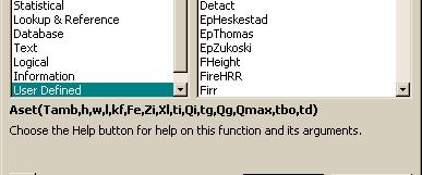
312 Module III: PROCESS Hand Calcs FIVE-Rev1 Joint Fire PRA Course, 2011, San Diego & Jacksonville Module III: Task 11a - Detailed Fire Modeling & Single Compartment Fire Scenarios Slide 15


313 CFAST Doorway Cable target locations and directions Liquid spray fire Burn roo m Target room Specified Leakage 110 kw gas burner fire Heptane Pa n Fire Mechanical ventilation supply 1.2 m below ceiling Ceiling exhaust vent Compartment Vent Controlled gas fire Kerosene Pan Fire Joint Fire PRA Course, 2011, San Diego & Jacksonville Module III: Task 11a - Detailed Fire Modeling & Single Compartment Fire Scenarios Slide 16

314 MAGIC Joint Fire PRA Course, 2011, San Diego & Jacksonville Module III: Task 11a - Detailed Fire Modeling & Single Compartment Fire Scenarios Slide 17


315 FDS Joint Fire PRA Course, 2011, San Diego & Jacksonville Module III: Task 11a - Detailed Fire Modeling & Single Compartment Fire Scenarios Slide 18
316 Module III: PROCESS Fire Detection/Suppression Analysis Assess fire detection timing Assess timing, reliability, and effectiveness of fixed fire suppression systems Assess manual fire brigade response Estimate probability of fire suppression as a function of time Workshop problem 11a-09 (file: 05_01_04 ) Corresponding PRA Standard SRs: FSS-D6, D7, D8 Joint Fire PRA Course, 2011, San Diego & Jacksonville Module III: Task 11a - Detailed Fire Modeling & Single Compartment Fire Scenarios Slide 19
317 Module III: PROCESS Calculate Severity Factor The time to target damage, and as a result the non-suppression probability, is a function of the postulated heat release rate The severity factor should be calculated in combination with the non-suppression probability Workshop problem 11a-10, 11a-11 (file: 05_01_04 ) Corresponding PRA Standard SRs: FSS-C4, D5 Joint Fire PRA Course, 2011, San Diego & Jacksonville Module III: Task 11a - Detailed Fire Modeling & Single Compartment Fire Scenarios Slide 20
318 Module III: PROCESS Calculate Fire Scenario Frequency Severity factor for scenario k λ = λ SF P k i, k k ns, k Ignition frequency for scenario k Integrated over all HRRs Non-suppression probability for scenario k Joint Fire PRA Course, 2011, San Diego & Jacksonville Module III: Task 11a - Detailed Fire Modeling & Single Compartment Fire Scenarios Slide 21
319 Module III: PROCESS Document Analysis Results The first tier documentation should be sufficient in detail to allow for an independent reader to understand Scenarios postulated, the basis for their selection and analysis, The tools utilized in the analysis and basis for selection, The final results of the analysis The second tier documentation should provide the details of each individual analysis performed including: Details of scenario selection process, The fire modeling analyses performed All specific considerations and assumptions should be recorded clearly. Joint Fire PRA Course, 2011, San Diego & Jacksonville Module III: Task 11a - Detailed Fire Modeling & Single Compartment Fire Scenarios Slide 22
320 EPRI/NRC-RES FIRE PRA METHODOLOGY Module III Detection and Suppression Appendix P Joint RES/EPRI Fire PRA Course Fall 2011 San Diego & Jacksonville
321 DETECTION & SUPPRESSION Objectives The objectives of this module are: Describe the process for calculating the non-suppression probability Describe the assumptions underlying the recommended approach for determining the non-suppression probability. Related SR: FSS-C7 Joint Fire PRA Course, 2011, San Diego & Jacksonville Module III: Detection and Suppression Appendix P Slide 2
322 DETECTION & SUPPRESSION Generalities State of the art fire models do not have the capabilities of modeling the effects of all the different fire detection and suppression strategies available in NPP fire scenarios. Time to target damage and non suppression probabilities are independent calculations The time to target damage is an input to the detection/suppression analysis Joint Fire PRA Course, 2011, San Diego & Jacksonville Module III: Detection and Suppression Appendix P Slide 3
323 DETECTION & SUPPRESSION Crediting a Fire Det or Supp System Detection and suppression systems can be credited in the fire PRA if they are effective and available Effectiveness Will the system detect/control the fire? Designed, installed and maintained according to the code of record and fire protection engineering judgment Based on the specific characteristics of the postulated fire scenario Availability Probability of the system operating upon demand Joint Fire PRA Course, 2011, San Diego & Jacksonville Module III: Detection and Suppression Appendix P Slide 4
324 DETECTION & SUPPRESSION Fire Detection and Suppression Systems The following fire detection and suppression systems are considered in the recommended approach: Fire Detection Prompt detection Automatic detection Delayed detection Fire Suppression Prompt suppression Automatic suppression Manual suppression Joint Fire PRA Course, 2011, San Diego & Jacksonville Module III: Detection and Suppression Appendix P Slide 5
325 DETECTION & SUPPRESSION Detection-Suppression Event Tree Fire Prompt Automatic Manual Detection Suppression Detection Suppression Detection Fire Brigade Sequence End State A OK B OK C OK D NS E OK F OK G NS H OK I OK J NS Joint Fire PRA Course, 2011, San Diego & Jacksonville Module III: Detection and Suppression Appendix P Slide 6
326 DETECTION & SUPPRESSION Event Tree Changes if Applying FAQ-50 Solution FAQ 50 changes the detection/suppression event tree: Collapses manual/fixed and fire brigade into one top event manual suppression Manual suppression top event credits any plant personnel suppressing fire, not just the fire brigade (all actors) For plant specific cases: Top event manual suppression can include manual actuation of fixed suppression, but timing may be different (i.e., the generic PNS curves may not apply) and dependencies must be addressed FAQ 50 solution assumes no delay in initiating manual fire fighting Per NRC closure memo if manual actuation of fixed suppression is credited, plant specific analysis must be performed and must address: procedures and training for manually actuating a fixed suppression system, and explain how dependencies between manual actuation of a fixed suppression system and other manual suppression activities.(e.g., manual suppression by portable extinguishers and hose stream) are addressed. Joint Fire PRA Course, 2011, San Diego & Jacksonville Module III: Detection and Suppression Appendix P Slide 7
327 DETECTION & SUPPRESSION Prompt Detection and Suppression Prompt detection Assume 1.0 if a continuous fire watch is credited or in-cabinet detection is available for fires postulated inside cabinets Justify the use of 1.0 if an incipient fire detection system is available Assume 0 if automatic ti or delayed d detection ti only are credited d Prompt suppression Credit prompt suppression in hot work fire scenarios Probability is obtained from the welding suppression curve Joint Fire PRA Course, 2011, San Diego & Jacksonville Module III: Detection and Suppression Appendix P Slide 8
328 DETECTION & SUPPRESSION Automatic Detection and Suppression Automatic detection Assume a probability of failure no larger than This the unreliability for halon systems reported in NSAC 179L. Check for availability! Automatic suppression (from NSAC 179L) Halon systems stems = CO 2 systems = 0.04 Wet pipe sprinklers = 0.02 Deluge or pre-action = 0.05 Check for availability! Joint Fire PRA Course, 2011, San Diego & Jacksonville Module III: Detection and Suppression Appendix P Slide 9
329 DETECTION & SUPPRESSION Delayed Detection and Suppression Delayed detection Assume 1.0 All fires will eventually be detected Compare time to target damage Vs time to detection and suppression Delayed suppression Probability of fire brigade suppression is obtained from the suppression curves Manual actuation of fixed fire suppression systems should include human reliability analysis. Joint Fire PRA Course, 2011, San Diego & Jacksonville Module III: Detection and Suppression Appendix P Slide 10
330 FAQ : Incipient Fire Detection Issue The guidance is silent on the topic of incipient detection systems Resolution Provide guidance on the treatment of incipient fire detection systems An incipient fire detection system is considered one that provides very early warning. Systems design to detect faulting electrical equipment or other overheating materials before an actual fire breaks out Example: aspirated smoke or ionization particle detection type systems FAQ largely based on knowledge about the use of incipient fire detection systems in the telecommunications industry. Reference: EPRI , Supplement 1 to NUREG/CR Joint Fire PRA Course, 2011, San Diego & Jacksonville Module III: Detection and Suppression Appendix P Slide 11
331 FAQ : Solution Credit systems for electrical/electronic component fires: Less than 250vdc or 480vac Excluding HEAF Excluding cabinets with certain fast-acting failure components such as electrical/electronic circuit boards that contain electrolytic capacitors, chart recorder drives, cooling fan motors, mechanical timers driven by electric motors, etc. Need to assess system availability and reliability Need to assess human response to alarm See NRC closure memo for additional cautions and guidance Credit acts as, in effect, large reduction in PNS given: early detection presence of a trained operator who acts to limit size and growth rate of fire such that damage outside cabinet is not expected Joint Fire PRA Course, 2011, San Diego & Jacksonville Module III: Detection and Suppression Appendix P Slide 12
332 FAQ : Solution Joint Fire PRA Course, 2011, San Diego & Jacksonville Module III: Detection and Suppression Appendix P Slide 13
333 FAQ : Solution Fault tree branch probability values Variable β: can be determined using the process provided by EPRI in report or set equal to 1E-02. Variable γ: calculate using detailed HRA analysis, 1E-02 if the system is addressable to multiple l cabinets or 5E-03 if the system is addressable to an individual cabinet. Variable ε 1 : may be set to 1E-3 Variable ε 2 : use manual suppression probability curve Joint Fire PRA Course, 2011, San Diego & Jacksonville Module III: Detection and Suppression Appendix P Slide 14
334 FAQ : References EPRI , Supplement 1 to NUREG/CR Joint Fire PRA Course, 2011, San Diego & Jacksonville Module III: Detection and Suppression Appendix P Slide 15
335 DETECTION & SUPPRESSION Suppression Curves The suppression curves were developed using FEDB data after 1/1/81 Developed with the suppression time field. If the suppression time was not available, the duration field was used. Data do not include supervised burn-outs, fires suppressed with automatic systems, or self-extinguished fires. Do not include time to detection or fire brigade response. Joint Fire PRA Course, 2011, San Diego & Jacksonville Module III: Detection and Suppression Appendix P Slide 16
336 FAQ : Manual Non-Suppression Probability Issue: NUREG/CR-6850/ gives too little credit to manual fire suppression before the fire brigade arrives on the scene compared to experience Resolution Updated guidance for treatment of manual suppression and the fire brigade response Includes a process to adjust the non-suppression analysis for scenario-specific fire brigade responses. Reference PRI , Supplement 1 to NUREG/CR Joint Fire PRA Course, 2011, San Diego & Jacksonville Module III: Detection and Suppression Appendix P Slide 17
337 FAQ : Solution How the P ns curves are calculated ns Original NUREG/CR-6850/ analysis used suppression time if available If no suppression time was given, fire duration was used (many such cases) FAQ uses the fire duration field for all events Fire duration is either the same (zero detection time) or longer than suppression time Result: the base P ns curves are slightly more conservative, but FAQ also assumes fire control and suppression activities start at the time of detection Credits suppression by plant personnel other than fire brigade Time delay for brigade arrival is no longer applied More than makes up for shift in curves New non-suppression (P ns ) curves for all bins Includes method to adjust for above or below average fire brigade response time Joint Fire PRA Course, 2011, San Diego & Jacksonville Module III: Detection and Suppression Appendix P Slide 18
338 FAQ : Solution The new P ns curves ns Joint Fire PRA Course, 2011, San Diego & Jacksonville Module III: Detection and Suppression Appendix P Slide 19
339 DETECTION & SUPPRESSION FAQ 50 changes the calculation of P ns Original 6850/ approach: λ Pns = e [ t ( t + t )] damage detection brigade response Revised FAQ 50 approach: [ ] λ t damage t detection Pns = e Joint Fire PRA Course, 2011, San Diego & Jacksonville Module III: Detection and Suppression Appendix P Slide 20
340 FAQ : Solution Electrical fires example for comparison Revised suppression rates are lower so base curve says you are less likely to put out fire in a given time Revised blue curve vs. original pink curve Not much difference You more than make up for that by not subtracting fire brigade response time from time available before damage Revised blue curve vs. original i orange curve that t includes a 10 minute brigade response time Joint Fire PRA Course, 2011, San Diego & Jacksonville Module III: Detection and Suppression Appendix P Slide 21
341 DETECTION & SUPPRESSION Revised Suppression Curves (1 of 2) Joint Fire PRA Course, 2011, San Diego & Jacksonville Module III: Detection and Suppression Appendix P Slide 22
342 DETECTION & SUPPRESSION Revised Suppression Curves (2 of 2) Joint Fire PRA Course, 2011, San Diego & Jacksonville Module III: Detection and Suppression Appendix P Slide 23
343 DETECTION & SUPPRESSION Selection of Suppression Curves The suppression curve should be selected based on the type of postulated fire. For prompt suppression by a welding fire watch, use the welding suppression curve If the fire watch is not successful, an appropriate suppression curve should be selected depending on the combustibles ignited due to hot work activities. Joint Fire PRA Course, 2011, San Diego & Jacksonville Module III: Detection and Suppression Appendix P Slide 24
344 DETECTION & SUPPRESSION Dependencies The following dependencies in suppression analysis could be important: Between automatic detection and suppression Example: control panel for a gaseous suppression system Between actuated barriers and fire suppression systems Between safe shutdown capabilities and automatic suppression Example: crediting fire fighting water for core injection, heat removal or secondary heat removal Between manual and automatic suppression Joint Fire PRA Course, 2011, San Diego & Jacksonville Module III: Detection and Suppression Appendix P Slide 25
345 DETECTION & SUPPRESSION Conceptual Example The scenario consists of an MCC fire affecting a target in the hot gas layer. The room is equipped with a smoke detection system and automatqic sprinklers Using fire modeling Time to smoke detection = 1 min Time to sprinkler activation = 8 min Time to target t damage = 15 min From fire drill records and/or plant procedures Time to delayed detection is assumed to be 15 min Joint Fire PRA Course, 2011, San Diego & Jacksonville Module III: Detection and Suppression Appendix P Slide 26
346 DETECTION & SUPPRESSION Example for the 6850/ approach Fire Prompt Automatic Manual Detection Suppression Detection Suppression Detection Fire Brigade Sequ uence End State FI PD PS AD AS MD FB A OK B OK C OK Pr(nonsuppression) 0.22 D NS 4.3E E OK F OK 0.24 G NS 4.8E H OK Time available for supp: 15-1 = 14 min Using the electrical curve P = EXP(-0.102x14) 14) P = 0.24 Failure automatic sprinklers: P = 0.02 (Requires justification for applicability) I OK 1 J NS 1.0E-03 Total 1.0E-02 P ns = D + G + P ns = 0.01 J Joint Fire PRA Course, 2011, San Diego & Jacksonville Module III: Detection and Suppression Appendix P Slide 27
347 DETECTION & SUPPRESSION Concluding Remarks The non-suppression probability is credited in Task 11, detailed fire modeling Target damage is evaluated assuming no detection/suppression capabilities in the room The time to target damage is an input to the detection and suppression analysis. The recommended approach includes an event tree capturing prompt, automatic, and delayed detection and suppression capabilities The event tree may need to be modified depending on the scenario Joint Fire PRA Course, 2011, San Diego & Jacksonville Module III: Detection and Suppression Appendix P Slide 28
348 EPRI/NRC-RES FIRE PRA METHODOLOGY Module III Task 11, Special Fire Models Part 1 Joint RES/EPRI Fire PRA Course Fall 2011 San Diego & Jacksonville
349 FIRE MODELS Generally computational fire models are developed to estimate extent and timing of fire growth There are fire scenarios critical i to NPP applications i that are beyond capability of existing computational fire models Special models are developed for prediction of consequences of such scenarios, based on a combination of: Fire experiments, Operating experience, actual fire events Engineering judgment Joint Fire PRA Course, 2011, San Diego & Jacksonville Module III: Task 11, Special Fire Models Part 1 Slide 2
350 SPECIAL MODELS Cable fires (modified from IPEEE approaches) Cable tray stack and fire spread models High energy arcing faults (new) Switchgear room Fire propagation to adjacent cabinets (consolidation) Relay room Passive fire protection features (consolidation) Joint Fire PRA Course, 2011, San Diego & Jacksonville Module III: Task 11, Special Fire Models Part 1 Slide 3
351 SPECIAL MODELS (Part 2) Main control board (new) Hydrogen fires (new) Turbine generator fires (new) Joint Fire PRA Course, 2011, San Diego & Jacksonville Module III: Task 11, Special Fire Models Part 1 Slide 4
352 CABLE FIRES (1 of 9) No generalized analytical theory is available to accurately model cable fires in all possible configurations in commercial nuclear plants. Most of the information compiled for this appendix is in the form of flammability parameters derived from experiments or correlations also developed from experimental data. The amount of experimental evidence and analytical tools available to model cable tray fires is relatively small when compared to the vast number of possible fire scenarios that can be postulated for NPPs Simplification of these scenarios will be needed Joint Fire PRA Course, 2011, San Diego & Jacksonville Module III: Task 11, Special Fire Models Part 1 Slide 5
353 CABLE FIRES (2 of 9) Scenarios involving cable fires may start as: Self-ignited cable fires Postulate self ignited cable fires in unqualified cables only Self ignited it cable fires should be characterized by a cable mass ratio (mass of cables in the room / mass of cables in the plant) representative of the scenario. Cable mass ratio is equivalent to the severity factor Or as secondary fires caused by fixed or transient fire sources Cable fires caused by welding & cutting should be postulated in both qualified and unqualified cables. Joint Fire PRA Course, 2011, San Diego & Jacksonville Module III: Task 11, Special Fire Models Part 1 Slide 6
354 CABLE FIRES (3 of 9) Cable tray ignition: Simplified cases Joint Fire PRA Course, 2011, San Diego & Jacksonville Module III: Task 11, Special Fire Models Part 1 Slide 7
355 CABLE FIRES (4 of 9) Heat release rate from cable fires Q& = ct q& bs A q bs : bench scale heat release rate per unit area A: burning area Length of the ignition source times tray width Joint Fire PRA Course, 2011, San Diego & Jacksonville Module III: Task 11, Special Fire Models Part 1 Slide 8
356 CABLE FIRES (5 of 9) Flame spread Cbl Cable tray k f is a constant with a value of 0.01 m 2 /kw z f z f ( k & 1) = x Q p f Fire x p Joint Fire PRA Course, 2011, San Diego & Jacksonville Module III: Task 11, Special Fire Models Part 1 Slide 9
357 CABLE FIRES (6 of 9) 2 Flame spread model 4( q& f ) δ f v = π ( kρc)( ) 2 Horizontal trays T ig T amb δ is assumed to be 2 mm Cable tray q is assumed as 70 kw/m 2 Vertical trays z f δ is assumed to be z f q is assumed as 25 kw/m 2 Fire x p Joint Fire PRA Course, 2011, San Diego & Jacksonville Module III: Task 11, Special Fire Models Part 1 Slide 10
358 CABLE FIRES (7 of 9) Example Material properties PVC cables: K = kw/m K ρ = 1380 kg/m 3 C p = kj/kg K T 218 C XPE cables: K = kw/m K ρ = 1375 kg/m 3 C p = kj/kg K T 330 C T ig = 218 C T ig = 330 C Joint Fire PRA Course, 2011, San Diego & Jacksonville Module III: Task 11, Special Fire Models Part 1 Slide 11
359 CABLE FIRES (8 of 9) Example Horizontal trays Flame spread for XPLE cable = 0.3 mm/sec (~0.05 /min) Flame spread for PVC cable = 0.9 mm/sec (~0.2 /min) Joint Fire PRA Course, 2011, San Diego & Jacksonville Module III: Task 11, Special Fire Models Part 1 Slide 12
360 CABLE FIRES (9 of 9) Example Vertical spread in cables PE/PVC cables Cable tray z f The heat release rate for XPE cable is 178 kw/m 2. Using these inputs, the estimated flame spread is 11 mm/sec (2 ft/min) Joint Fire PRA Course, 2011, San Diego & Jacksonville Module III: Task 11, Special Fire Models Part 1 Fire Slide 13 x p
361 FIRE PROPAGATION IN CABLE TRAY STACKS WITH RG 1.75 SEPARATION (1 of 2) 35 o 35 o n = 3 n=2 n = 1 h Cable tray stack Ignition Source Characteristic length n +1 1 = L n + 2 n + 1 ( h Tan ( o ) L 35 Joint Fire PRA Course, 2011, San Diego & Jacksonville Module III: Task 11, Special Fire Models Part 1 Slide 14
362 FIRE PROPAGATION IN CABLE TRAY STACKS WITH RG 1.75 SEPARATION (2 OF 2) First tray to second tray: 4 minutes after ignition of first tray Second tray to third tray: 3 minutes after ignition of second first tray Third tray to fourth tray: 2 minutes after ignition of third tray Fourth tray to fifth tray: 1 minute after ignition of fourth tray Balance of trays in stack: 1 minute after ignition of fifth tray Joint Fire PRA Course, 2011, San Diego & Jacksonville Module III: Task 11, Special Fire Models Part 1 Slide 15
363 FIRE PROPAGATION IN CABLE TRAY STACKS WITH RG 1.75 SEPARATION (2 OF 2) (cont d) If there is a second stack of cable trays next to the first stack, spread to the first (lowest) tray in the second stack will be assumed to occur concurrent with spread of fire to the third tray in the original stack. Subsequent spread of fire in the second stack will mimic the continued growth of fire in the first stack (e.g., the second tray in the second stack will ignite within 2 minutes of the first tray in the second stack - at the same time as the fourth tray in the first stack.) Fire spread will occur at the same rate to stacks on either or both sides of the original stack Joint Fire PRA Course, 2011, San Diego & Jacksonville Module III: Task 11, Special Fire Models Part 1 Slide 16
364 FAQ : Cable Tray Fire Propagation Purpose & Scope Clarify use of the empirical model for fire propagation within a cable tray stack as presented in Appendix R of NUREG/CR-6850 EPRI TR The clarifications in the FAQ are limited to the use of the empirical model for fire propagation p in a cable tray stack Reference: EPRI , Supplement 1 to NUREG/CR Joint Fire PRA Course, 2011, San Diego & Jacksonville Module III: Task 11, Special Fire Models Part 1 Slide 17
365 FAQ :Solution The FAQ clarifies that the model for fire propagation among cable trays should be used only for the configurations described in Appendix R of NUREG/CR-6850 Angle of propagation Rate of propagation Cable tray stacks within the zone of influence DO NOT extend the model beyond, at most, three cable tray stacks Joint Fire PRA Course, 2011, San Diego & Jacksonville Module III: Task 11, Special Fire Models Part 1 Slide 18
366 FAQ : Ongoing and Future Work Research program by the NRC is underway to assess cable tray fire behavior (NIST) Full scale testing of fire propagation in cable trays Test for different cable types Measuring both heat release rate and flame propagation rates Intent is to develop better models and guidance for predicting cable fire behavior Joint Fire PRA Course, 2011, San Diego & Jacksonville Module III: Task 11, Special Fire Models Part 1 Slide 19
367 HIGH ENERGY ARCING FAULTS (1 of 15) Definition Rapid release of electrical energy in the form of heat, vaporized copper, and mechanical force. An arc is a very intense discharge of electrons between two electrodes that are carrying an electric current. The arc is created by the flow of electrons through charged particles of gas ions that exist as a result of vaporization of the conductive material. Joint Fire PRA Course, 2011, San Diego & Jacksonville Module III: Task 11, Special Fire Models Part 1 Slide 20
368 HIGH ENERGY ARCING FAULTS (2 of 15) Scope Switchgears Load centers More than 440 V Bus bars Oil filled outdoor transformers are addressed separately Bus ducts are addressed separately (via FAQ ) Joint Fire PRA Course, 2011, San Diego & Jacksonville Module III: Task 11, Special Fire Models Part 1 Slide 21
369 HIGH ENERGY ARCING FAULTS (3 of 15) General characteristics of switchgear based HEAF events (from FEDB) Indications of heavy smoke in the area, which may delay identification of the fire origin and whether the fire is still burning. In nearly all of these events, the HEAF initiates in the feed breaker cubicle, because this is where most of the electrical energy in a high-energy cabinet resides. HEAFs occurring in 480V switchgears did not report damage beyond the switchgear itself, but some resulted in the cabinet opening. Joint Fire PRA Course, 2011, San Diego & Jacksonville Module III: Task 11, Special Fire Models Part 1 Slide 22
370 HIGH ENERGY ARCING FAULTS (4 of 15) General characteristics of HEAF events (from FEDB) Initial use of fire extinguishers may be ineffective in severe HEAF events regardless of the extinguishing agent (CO2, Halon, or dry chemical). The fires were eventually suppressed with water by the fire brigade. No conclusions can be made regarding the effectiveness of fixed fire suppression systems for the ensuing fire. Only one event was successfully suppressed, with an automatic Halon system. Durations of the fires involving HEAF range from minutes to over an hour. The short durations generally reflect events that do not result in large ensuing fire(s), either in the device itself or external fires. Joint Fire PRA Course, 2011, San Diego & Jacksonville Module III: Task 11, Special Fire Models Part 1 Slide 23
371 HIGH ENERGY ARCING FAULTS (5 of 15) General characteristics of HEAF events (from FEDB) Sustained fires after the initial HEAF involve combustible materials (cable insulation, for the most part) near the cabinet. Damage may extend to cables and cabinets in the vicinity of the high-energy electrical cabinet. Damage to cabinet internals and nearby equipment (if observed) appears to occur relatively early in the event. Joint Fire PRA Course, 2011, San Diego & Jacksonville Module III: Task 11, Special Fire Models Part 1 Slide 24
372 HIGH ENERGY ARCING FAULTS (6 of 15) The arcing or energetic fault scenario in these electrical devices consists of two distinct phases, each with its own damage characteristics and detection/suppression response and effectiveness. The first phase is a short, rapid release of electrical energy followed by ensuing fire(s) that t may involve the electrical l device itself, as well as any external exposed combustibles, such as overhead exposed cable trays or nearby panels, that may be ignited during the energetic phase. Joint Fire PRA Course, 2011, San Diego & Jacksonville Module III: Task 11, Special Fire Models Part 1 Slide 25
373 HIGH ENERGY ARCING FAULTS (6 of 15) (cont d) The second phase, i.e., the ensuing fire(s), is treated similar to electrical cabinet fires described elsewhere in this procedure, with one distinction. Any closed electrical cabinet subject to a HEAF is opened to a fully ventilated fire. In dealing with postulated t switchgear and load center fires, both phases should be considered. Joint Fire PRA Course, 2011, San Diego & Jacksonville Module III: Task 11, Special Fire Models Part 1 Slide 26
374 HIGH ENERGY ARCING FAULTS (7 of 15) The zone of influence Joint Fire PRA Course, 2011, San Diego & Jacksonville Module III: Task 11, Special Fire Models Part 1 Slide 27
375 HIGH ENERGY ARCING FAULTS (8 of 15) High-Energy Phase: The zone of influence The initial arcing fault will cause destructive and unrecoverable failure of the faulting device, e.g., the feeder breaker cubicle, including the control and bus-bar sections. The next upstream over-current protection device in the power feed circuit leading to the initially faulting device will trip open, causing the loss of all components fed by that electrical bus. This fault may be recoverable if the initial faulting device can be isolated from the feeder circuit. The release of copper plasma and/or mechanical shock will cause the next directly adjoining/adjacent switchgear or load center cubicles within the same cabinet bank and in all directions (above, below, to the sides) to trip open. Joint Fire PRA Course, 2011, San Diego & Jacksonville Module III: Task 11, Special Fire Models Part 1 Slide 28
376 HIGH ENERGY ARCING FAULTS (9 of 15) High-Energy Phase: The zone of influence Any unprotected t cables that t drop into the top of the panel in an open air-drop configuration will ignite. Cables in conduit or in a fire wrap are considered protected in this context. In other words, if cables are protected (i.e., not exposed) by conduit or fire wrap, they are assumed damaged, but not ignited, and they do not contribute to the fire load. Armored cables with an exposed plastic covering are considered unprotected in this context. Exposed cables, or other exposed flammable or combustible materials or transient fuel materials located within this same region (0.9 m (3 ) horizontally) will be ignited. Joint Fire PRA Course, 2011, San Diego & Jacksonville Module III: Task 11, Special Fire Models Part 1 Slide 29
377 HIGH ENERGY ARCING FAULTS (10 of 15) High-Energy Phase: The zone of influence Any unprotected cables in the first overhead cable tray will be ignited concurrent with the initial arcing fault provided that this first tray is within 1.5 m (5 ) vertical distance of the top of the cabinet. The cable tray fire will propagate p to additional trays consistent with the approach provided for the treatment of cable tray fires elsewhere in this document, assuming that the time to ignition of the first tray is zero rather than the normal 5 minutes. This applies to any cable tray located directly above the panel. This applies to any cable tray above the aisle way directly in front of, or behind, the faulting cabinet, provided some part of that tray is within 0.3 m (12") horizontally of the cabinet s front or rear face panel. Cables in conduit or in a fire wrap are considered protected in this context. Armored cables with an exposed plastic covering are considered unprotected in this context Joint Fire PRA Course, 2011, San Diego & Jacksonville Module III: Task 11, Special Fire Models Part 1 Slide 30
378 HIGH ENERGY ARCING FAULTS (11 of 15) High-Energy Phase: The zone of influence Any vulnerable component or movable/operable structural element located within 0.9 m (3' ) horizontally of either the front or rear panels/doors, and at or below the top of the faulting cabinet section, will suffer physical damage and functional failure. This will include mobile/operable structural elements like fire dampers and fire doors. This will include potentially vulnerable electrical or electromechanical components such as cables, transformers, ventilation fans, other cabinets, etc. This will exclude fixed structural elements such as walls, floors, ceilings, and intact penetration seals. This will exclude large components and purely mechanical components such as large pumps, valves, major piping, fire sprinkler piping, or other large piping (1" diameter or greater). This may include small oil feed lines, instrument air piping, or other small piping i (less than 1" diameter). Joint Fire PRA Course, 2011, San Diego & Jacksonville Module III: Task 11, Special Fire Models Part 1 Slide 31
379 HIGH ENERGY ARCING FAULTS (12 of 15) Detection and Suppression The amount of smoke from any damaging HEAF event is expected to activate any smoke detection system in the area. Manual suppression by plant personnel and the fire brigade may be credited to control and prevent damage outside the initial ZOI from ensuing fires. Separate suppression curves are developed eloped for these fires documented in Appendix P to the Fire Modeling procedure. Joint Fire PRA Course, 2011, San Diego & Jacksonville Module III: Task 11, Special Fire Models Part 1 Slide 32
380 HIGH ENERGY ARCING FAULTS (13 of 15) Modeling HEAF in the Fire PRA Identify the equipment in the room where a HEAF can be generated. As indicated earlier, this equipment includes, for the most part, 4160 V to 440 V switchgear cabinets, load centers, and bus bars. Two types of initiating events should be postulated for each identified equipment: A HEAF event with an ensuing fire, and A regular equipment fire (no HEAF). Joint Fire PRA Course, 2011, San Diego & Jacksonville Module III: Task 11, Special Fire Models Part 1 Slide 33
381 HIGH ENERGY ARCING FAULTS (14 of 15) Non-Suppression Probability and Severity Factors Assign a generic frequency for HEAFs listed in Task 6, and apportion it with the location and ignition source weighting factors to the equipment under analysis. Assume targets in the ZOI are damaged at time zero. The probability of no manual suppression for the targets in the ZOI is 1.0. The severity factor for a scenario consisting i of targets in the ZOI only is 1.0. Probability of no automatic suppression for targets in the ZOI is 1.0 The probability of no manual suppression for targets outside the ZOI can be calculated using the detection suppression event tree described in Appendix P, with the HEAF manual suppression curve. Joint Fire PRA Course, 2011, San Diego & Jacksonville Module III: Task 11, Special Fire Models Part 1 Slide 34
382 HIGH ENERGY ARCING FAULTS (15 of 15) Example Consider a HEAF scenario consisting of a switchgear cabinet affecting two targets. A stack of three cable trays is above the cabinet. The first tray in the stack is 0.9 m (3 ) above the cabinet. It has been determined d that t one of the targets t is in the first tray. The other target is in the third tray. According to the approach provided in Section M.3, the first target is assumed ignited at the time of the HEAF. The second target is damaged at time 7 minutes (4 minutes for fire propagation from the first to the second tray, and 3 minutes for fire propagation p from the second to the third tray). CDF = λ W CCDP A scenario involving target in the first tray i g L is A scenario involving the two targets CDFi = λg WL Wis Pns CCDPi W i Joint Fire PRA Course, 2011, San Diego & Jacksonville Module III: Task 11, Special Fire Models Part 1 Slide 35
383 FAQ Bus Duct HEAF Issue: The guidance was silent on bus duct fires Resolution: This was an unintended oversight Evidence for bus duct HEAF exists Diablo Canyon, May 2000 Columbia, August 2009 A method for bus duct HEAF was developed Reference: EPRI , Supplement 1 to NUREG/CR Joint Fire PRA Course, 2011, San Diego & Jacksonville Module III: Task 11, Special Fire Models Part 1 Slide 36
384 BUS DUCT HEAF (1 of 4) Bus duct physical configurations can influence the HEAF event. Four basic types: Cable ducts Nonsegmented or continuous bus ducts Segmented bus ducts Iso-phase bus ducts HEAF only associated with segmented and iso-phase Separate approaches developed for segmented and iso-phase ducts No HEAF for cable ducts or non-segmented ducts Joint Fire PRA Course, 2011, San Diego & Jacksonville Module III: Task 11, Special Fire Models Part 1 Slide 37
385 BUS DUCT HEAF (2 of 4) General characteristics of bus duct HEAF events Rapid release of energy Potential for physical and thermal damage Potential for secondary fires Potential for release of molten metals Joint Fire PRA Course, 2011, San Diego & Jacksonville Module III: Task 11, Special Fire Models Part 1 Slide 38
386 BUS DUCT HEAF (3 of 4) Zone of influence of HEAF events for segmented bus ducts. Assume HEAF event at transition points of segmented bus ducts Molten metal to be ejected from bottom of the bus duct in right conical form at 15 o angle Molten metal to be ejected outward up to 1.5 feet spherical zone of influence Subsequent fires depend on cables and other combustible materials within the zone of influence Joint Fire PRA Course, 2011, San Diego & Jacksonville Module III: Task 11, Special Fire Models Part 1 Slide 39
387 BUS DUCT HEAF (4 of 4) Analyzing HEAF events for iso-phase bus ducts. Assume a 5 foot spherical damage zone centered at the fault point Covers initial fault and hydrogen gas explosion and fire Subsequent fires depend on cables and other combustible materials within the zone of influence If fault is assumed at main transformer termination point, oil fire may need to be considered Joint Fire PRA Course, 2011, San Diego & Jacksonville Module III: Task 11, Special Fire Models Part 1 Slide 40
388 FIRE PROPAGATION TO ADJACENT ELECTRICAL CABINETS (1 of 3) Analytical fire models may be used in all types of fire propagation and damage scenarios. This appendix discusses empirical approaches for determining: Fire propagation to adjacent cabinets Fire induced damage in adjacent cabinets Empirical approach based on SNL and VTT experiments Joint Fire PRA Course, 2011, San Diego & Jacksonville Module III: Task 11, Special Fire Models Part 1 Slide 41
389 FIRE PROPAGATION TO ADJACENT ELECTRICAL CABINETS (2 of 3) The empirical model for fire propagation consists of the following rules: Assume no fire spread if either: Cabinets are separated by a double wall with an air gap, or Either the exposed or exposing cabinet has an open top, and there is an internal wall, possibly with some openings, and there is no diagonal cable run between the exposing and exposed cabinet. If fire spread cannot be ruled out, or cabinets are separated by a single metal wall, assume that no significant heat release occurs from the adjacent cabinet for 10 minutes if cables in the adjacent cabinet are in direct contact with the separating wall, and 15 minutes if cables are not in contact with the wall. Joint Fire PRA Course, 2011, San Diego & Jacksonville Module III: Task 11, Special Fire Models Part 1 Slide 42
390 FIRE PROPAGATION TO ADJACENT ELECTRICAL CABINETS (3 of 3) The empirical model for fire damage consists of the following rules: Assume loss of function in an adjacent cabinet if there is not a double wall with an air gap. Assume no damage in the second adjacent cabinet occurs until after the fire propagates to the adjacent cabinet. Assume damage can occur earlier if there are large openings in a wall and plenum areas in which a hot gas layer is likely to form. Assume no damage to an adjacent cabinet if: There is a double wall with an air gap, and There are no sensitive electronics in the adjacent cabinet (or the sensitive electronics have been qualified above 82 o C). Assume damage to sensitive electronics occurs at 10 minutes if there is a double wall with an air gap. Assume damage to sensitive electronics can be prevented before 10 minutes if the fire is extinguished and the cabinet is cooled, e.g., by CO 2 extinguishers. Joint Fire PRA Course, 2011, San Diego & Jacksonville Module III: Task 11, Special Fire Models Part 1 Slide 43
391 PASSIVE FIRE PROTECTION FEATURES (1 of 7) Most of the fire protection capabilities of passive fire protection o features es cannot be evaluated ed using analytical a fire modeling tools. Empirical approaches Limited it analytical l approaches Probabilistic approaches Joint Fire PRA Course, 2011, San Diego & Jacksonville Module III: Task 11, Special Fire Models Part 1 Slide 44
392 PASSIVE FIRE PROTECTION FEATURES (2 of 7) Passive fire protection refers to fixed features put in place for reducing or preventing fire propagation. Some examples are: Coatings Cable tray barriers Fire stops Dampers Penetration seals Doors Walls Empirical approach Probabilistic approach Limited analytical approach Joint Fire PRA Course, 2011, San Diego & Jacksonville Module III: Task 11, Special Fire Models Part 1 Slide 45
393 PASSIVE FIRE PROTECTION FEATURES (3 of 7) The analytical approach for modeling the response of passive fire protection features to fire generated conditions consists of a heat transfer analysis. The boundary conditions are the fire generated conditions. In general, these consist of the heat flux exchanges at the surface of the passive feature. Thermo-physical properties of the material are necessary. These properties are readily available for some materials like concrete or steel. Models can be used for estimating the temperature profile throughout the thickness of the barrier Effects of cracks and gaps in doors or walls should be evaluated only with the objective of analyzing smoke migration. Joint Fire PRA Course, 2011, San Diego & Jacksonville Module III: Task 11, Special Fire Models Part 1 Slide 46
394 PASSIVE FIRE PROTECTION FEATURES (4 of 7) Empirical approaches are possible if you can match your conditions to the fire tests that have been performed SNL tests performed in the 1970 s on several coatings Cable tray configurations included single cable tray and a two-tray stack Exposure fires included gas burner or diesel fuel pool fire Tests results: coated nonqualified cables did not ignite for at least 12 minutes coated, nonqualified cables did not fail for at least 3 minutes and in some cases 10 minutes or more. Tests are very difficult to extrapolate high plant-to-plant to variability A basis needs to be established for any credit given to coatings Joint Fire PRA Course, 2011, San Diego & Jacksonville Module III: Task 11, Special Fire Models Part 1 Slide 47
395 PASSIVE FIRE PROTECTION FEATURES (5 of 7) The empirical approaches consist of replicating the thermal response of fire protection features observed in fire tests in the postulated fire scenarios. Cable tray barriers and fire stops: SNL tests Same configuration as coating tests The following systems were tested: Ceramic wool blanket wrap, solid tray bottom covers, solid tray top cover with no vents, solid tray bottom cover with vented top cover, one-inch insulating barrier between cable trays, and fire stops. Propagation of the fire to the second tray was prevented in each case. Again, a basis needs to be established for any credit taken Tests are not definitive for all cases Joint Fire PRA Course, 2011, San Diego & Jacksonville Module III: Task 11, Special Fire Models Part 1 Slide 48
396 PASSIVE FIRE PROTECTION FEATURES (6 of 7) Barriers seem to substantially delay cable damage for qualified cable. The barriers did not delay cable damage for nonqualified cable. Results considered most appropriate to exposure fires with smaller HRR and to cable trays in a stack threatened by fires in lower trays. Each barrier prevents cable tray ignition until well after the fire brigade reaches the scene (i.e., greater than 20 minutes), Each barrier prevents damage in qualified cable with solid tray bottom covers until well after the fire brigade reaches the scene. Again: use the test data, but establish a basis for your application! Joint Fire PRA Course, 2011, San Diego & Jacksonville Module III: Task 11, Special Fire Models Part 1 Slide 49
397 PASSIVE FIRE PROTECTION FEATURES (7 of 7) Probabilistic modeling of passive fire suppression systems Dampers: Equipment unavailability obtained from inspection results Penetration seals: Equipment unavailability obtained from inspection results Joint Fire PRA Course, 2011, San Diego & Jacksonville Module III: Task 11, Special Fire Models Part 1 Slide 50
398 EPRI/NRC-RES FIRE PRA METHODOLOGY Module III Task 11, Special Fire Models Part 2 Joint RES/EPRI Fire PRA Workshop Fall 2011 San Diego & Jacksonville
399 Module III-11, Pt. 2: Special Models Part 2 Scope of this Module Module III-11, Pt. 2 covers the three remaining Special Models Main Control Board Fires (Appendix L) Turbine Generator (TG) Set Fires (Appendix O) Hydrogen Fires (Appendix N) Fire PRA Workshop, 2011, San Diego & Jacksonville Module III Pt. 2: Special Fire Models Part 2 Slide 2
400 Module III-11, Pt. 2: Special Models Part 2 Main Control Board Damage Likelihood Model The main control board (MCB) presents many analysis challenges Design practices vary widely Configuration of the boards themselves Relay rack room versus main control room Separation and partitioning within MCB MCB may be important to risk, but IPEEE vintage approaches were identified as a weakness of those studies Fire models cannot currently predict in-panel fire behavior, so an alternative approach is needed A method is provided to assess the likelihood that a fire in the MCB will grow large enough to damage a specific target set as defined by a specific physical region of the board Fire PRA Workshop, 2011, San Diego & Jacksonville Module III Pt. 2: Special Fire Models Part 2 Slide 3
401 Module III-11, Pt. 2: Special Models Part 2 Main Control Board Damage Likelihood Model The MCB model is built on several assumptions that are specific to the MCB and the MCR MCB fire frequency partitioning approach Suppression times for MCR fires Fire characteristics of a MCR type control panel (peak HRR and growth profile) Damage limits for control components This model applies ONLY to the MCB itself Not intended for other electrical cabinets/panels Not intended for MCR back-panels Not intended for the relay room or other similar areas Fire PRA Workshop, 2011, San Diego & Jacksonville Module III Pt. 2: Special Fire Models Part 2 Slide 4
402 Module II-11, Pt. 2: Special Models Part 2 Main Control Board Damage Likelihood Model To use the model you must first identify your target set Example: two control switches on the MCB Determine the separation distance between the most remote members of the damage set (those furthest apart) Consider cable routing within the panel! Using this distance, go to the probability curve and estimate the conditional probability bilit that t given a fire somewhere in the MCB, the specific zone encompassing the target set will be damaged The resulting number includes BOTH the severity factor AND the probability of non-suppression It does not include fire frequency! Fire PRA Workshop, 2011, San Diego & Jacksonville Module III Pt. 2: Special Fire Models Part 2 Slide 5
403 Module III-11, Pt. 2: Special Models Part 2 Main Control Board Damage Likelihood Model Example: Target set is two switches Probability bilit of Target Damage: [SF * P ns ](d) located 0.5 m apart from each other 1.00E-01 Inspection shows that the cables leading to each switch are routed in opposite directions such that 0.5 m is the minimum separation distance between the switches The MCB contains only IEEE- 383 certified low-flame-spread cables The conditional probability that a fire occurring somewhere in the MCB will damage the target set is approximately 3.0E E E E E Damage Distance [m] Qualified Unqualified Fire PRA Workshop, 2011, San Diego & Jacksonville Module III Pt. 2: Special Fire Models Part 2 Slide 6
404 Main Control Room Fire Analysis Step 8: Fire Growth... (cont d) A probabilistic model of fire spread in the main control board estimates the likelihood that a set of targets separated by a predetermined distance would be affected by a fire. Difficult to model fire spread within a cabinet using current state-of-the-art the art analytical tools. Probabilistic model based on EPRI s Fire Events Database and cabinet fire experiments reported in NUREG/CR The likelihood is a combination of severity factors and nonsuppression probabilities λ( d) =λ MCB [ SF P ]( d) ns Fire PRA Workshop, 2011, San Diego & Jacksonville Module III Pt. 2: Special Fire Models Part 2 Slide 7
405 Main Control Room Fire Analysis Step 8: Fire Growth... (cont d) The likelihood is a combination of severity factors and non-suppression probabilities integrated over all possible fire events inside the panel that may damage the postulated target set. All possible fire origin locations d h H λ ( d ) =λ MCB [ SF P ]( d ) ns φ w W [ SF P ns ]( d) = 1 H WW HW H 0 0 SF ( d, w, h) P ns ( d, w, h) dwdh Fire PRA Workshop, 2011, San Diego & Jacksonville Module III Pt. 2: Special Fire Models Part 2 Slide 8
406 Module II-11, Pt. 2: Special Models Part 2 Turbine Generator Set Fires Four types of fires can occur involving the turbine generator set, and each is treated differently: Electrical fires in the exciter Hydrogen fires General oil fires Catastrophic failure (e.g., blade ejection) Fire PRA Workshop, 2011, San Diego & Jacksonville Module III Pt. 2: Special Fire Models Part 2 Slide 9
407 Module III-11, Pt. 2: Special Models Part 2 Turbine Generator Set Fires: Exciter Fires Exciter fires do occur, but all evidence indicates fires remain small and non-threatening No evidence of any exciter fire that led to damage to anything other than the exciter itself No attempt was made to estimate likelihood of a severe exciter fire (one that challenges external targets) Recommended Practice: Assume exciter fires remain confined to the exciter Verify for your application, but should not represent a significant risk contributor Fire PRA Workshop, 2011, San Diego & Jacksonville Module III Pt. 2: Special Fire Models Part 2 Slide 10
408 Module III-11, Pt. 2: Special Models Part 2 Turbine Generator Set Fires: Hydrogen Fires Database shows 13 T/G set hydrogen fires, two categorized as severe, with the rest being fires due to small leaks (generally associated with seals) with limited damage range For small fires: Assume damage will be limited to within a few feet of the point of release Secondary ignitions should be considered and treated if there are nearby combustibles See more in Hydrogen Fires discussion (Appendix N) Fire PRA Workshop, 2011, San Diego & Jacksonville Module III Pt. 2: Special Fire Models Part 2 Slide 11
409 Module III-11, Pt. 2: Special Models Part 2 Turbine Generator Set Fires: Hydrogen Fires For severe fires, widespread damage may occur due to an explosion or detonation of the hydrogen gas. Assume fire may damage all Fire PRA cables and equipment within the line of site of the generator and its bearings (including above and below) Hydrogen explosion could cause some structural damage as well For further discussion see Hydrogen Fires Fire PRA Workshop, 2011, San Diego & Jacksonville Module III Pt. 2: Special Fire Models Part 2 Slide 12
410 Module III-11, Pt. 2: Special Models Part 2 Turbine Generator Set Fires: Catastrophic Failure International experience includes a few fires initiated by catastrophic turbine failure that resulted in widespread damage including structural damage Examples: Vandellos (1989), Narora (1993), Chernobyl Unit 2 (1991) Events involved a combination of turbine blade ejection, hydrogen release, and large oil fires. Domestically, only one event came close to involving all of these elements (Salem, 1991) Event involved minor damage due to existence of an automatic suppression system and prompt fire brigade response Indicates that both automatic fire suppression systems and fire brigade should be credited to prevent catastrophic consequences Fire PRA Workshop, 2011, San Diego & Jacksonville Module III Pt. 2: Special Fire Models Part 2 Slide 13
411 Module III-11, Pt. 2: Special Models Part 2 Turbine Generator Set Fires: Catastrophic Failure Screening approach: assume the conditional probability that, given a T/G set fire, the event will involve catastrophic failure (e.g., blade ejection), hydrogen, and oil fires is: 1 over 38 events or With successful suppression, damage would be limited to the T/G system, as was the case at Salem In case of failure of all suppression, automatic and manual, assume loss of all Fire PRA cables and equipment in the Turbine Building Possible failure of exposed structural steel as well Related SRs: FSS-F1, F2, F3 Estimate screening CDF contribution, refine as appropriate Fire PRA Workshop, 2011, San Diego & Jacksonville Module III Pt. 2: Special Fire Models Part 2 Slide 14
412 Module III-11, Pt. 2: Special Models Part 2 Hydrogen Fires This discussion (Appendix N) applies to general hydrogen fires Including T/G set fires Also fires from other sources of hydrogen leaks and releases (e.g., recombiners, storage tanks, piping, etc.) The intent was to provide general discussion of hydrogen fires and their potential effects The discussion i stops short of recommending modeling approaches, but does provide references to various information resources Fire PRA Workshop, 2011, San Diego & Jacksonville Module III Pt. 2: Special Fire Models Part 2 Slide 15
413 Module III-11, Pt. 2: Special Models Part 2 Hydrogen Fires Two general types of fires: Jet fires originating at point of a H 2 leak Critical question will be flame length Explosions If there is a mechanism for the release of large quantities of H 2 (e.g., a large leak, a prolonged leak that might not be ignited early), then likelihood of a hydrogen explosion is high References provide additional resources for assessing damage potential for an explosion scenario Critical question will be the severity of the overpressure Fire PRA Workshop, 2011, San Diego & Jacksonville Module III Pt. 2: Special Fire Models Part 2 Slide 16

414 EPRI/NRC-RES RES FIRE PRA METHODOLOGY Module III Task 11b: Main Control Room Fire Analysis and Appendix L Joint RES/EPRI Fire PRA Workshop Fall 2011 San Diego & Jacksonville
415 Main Control Room Fire Analysis Objectives The objective of this module is: Describe the recommended approach for detailed fire modeling in the main control room. Specifically: Differences between the main control room and other compartments Criteria for abandonment due to fire generated environmental conditions Description of how to analyze: Conditional probability of damage to a target set Forced control room abandonment time Fire PRA Workshop, 2011, San Diego & Jacksonville Task 11b - Main Control Room Fire Analysis Slide 2
416 Main Control Room Fire Analysis What is Different in the MCR? The control and instrumentation circuits of all redundant trains for almost all plant systems are present in the control room. Redundant train controls can be within a short distance of each other Small fires within control panels could be risk-significant Related SR: FSS-A6 The room is continuously occupied, which provides the capability for prompt detection and suppression. Evaluating ating control room abandonment conditions is necessary Abandonment refers to situations in which control room operators are forced to leave due to untenable fire generated conditions (temperature, toxicity, and visibility). Related SRs: FSS-B and its two SRs Fire PRA Workshop, 2011, San Diego & Jacksonville Task 11b - Main Control Room Fire Analysis Slide 3
417 Main Control Room Fire Analysis Recommended Steps Step 1: Identify and characterize main control room features Step 2: Estimate control room fire frequency Step 3: Identify and characterize fire detection and suppression features and systems Step 4: Characterize alternate shutdown features Step 5: Identify and characterize target sets Step 6: Identify and characterize ignition sources Step 7: Define fire scenarios Step 8: Conduct fire growth and propagation analysis Step 9: Fire detection and suppression analysis and severity factor Step 10: Estimate failure probability of using alternate shutdown features Step 11: Estimate probability of control room abandonment Step 12: Calculate scenario frequencies Step 13: Document analysis results Fire PRA Workshop, 2011, San Diego & Jacksonville Task 11b - Main Control Room Fire Analysis Slide 4
418 Main Control Room Fire Analysis Step 1: Identify and Characterize MCR Features The specific features of the control room and the control board are identified. Control room dimensions Other adjacent compartments included in the MCR proper Location, shape, dimensions and special features of the control panels and other electrical panels Main control board layout and location of various controls and displays Cable penetration into the control room and into the control panels Ventilation system characteristics False ceiling features and the ceiling above it Problem Set 11b-01 (Example) (file: 05_01_05 ) 01 Fire PRA Workshop, 2011, San Diego & Jacksonville Task 11b - Main Control Room Fire Analysis Slide 5
419 Main Control Room Fire Analysis Step 4: Characterize Alternate Shutdown Features The features of alternate shutdown capability vary widely among NPPs In general, a control panel is installed at a location away from the control room where the operators can control and monitor key core cooling functions and parameters independent of the MCR. In other plants, alternate shutdown capability is achieved through a set of control points and control panels located at various points of the plant requiring coordinated actions of several operators. It is necessary for the fire risk analysts to understand the alternate shutdown capability of the plant. For example, the analyst may select safety-related target sets on the panel that are not backed up by an alternate shutdown control or instrumentation circuit. Problem Set 11b-04 (Example) (file: 05_01_05 ) Fire PRA Workshop, 2011, San Diego & Jacksonville Task 11b - Main Control Room Fire Analysis Slide 6
420 Main Control Room Fire Analysis Step 5: Identify and Characterize Target Sets The target sets can be identified by systematically examining combinations of control and instrumentation items found on the control panels, electrical cabinets, wireways, and cable raceways inside the MCR. Examine the control panels from one end to the other Groups of adjacent controls and instrumentation Cursory and conservative estimation of the CCDP/CLERP as the basis Elements of a set are located within the reach of a potential fire Exposure fire affecting multiple cabinets Problem Set 11.b-05 (file: 05_01_05 ) Corresponding PRA Standard SRs: FSS-A2 through A4 Fire PRA Workshop, 2011, San Diego & Jacksonville Task 11b - Main Control Room Fire Analysis Slide 7
421 Main Control Room Fire Analysis Step 6: Identify and Characterize Ignition Sources The final product of this step is a list of ignition sources, their relevant characteristics, and fire ignition frequencies associated with each source Similar to Step 3.a of single compartment analysis Type, quantity, dimensions and heat release rate profile of each source Main control board as ignition source Assume fire might occur at any point on a control panel Other control panels, electrical cabinets, wireways, and cable raceways Kitchen appliances and other electrical devices? Transient combustible fires Problem Set 11.b-06 (file: 05_01_05 ) 01 Fire PRA Workshop, 2011, San Diego & Jacksonville Task 11b - Main Control Room Fire Analysis Slide 8
422 Main Control Room Fire Analysis Step 7: Define Fire Scenarios Four types of fire scenarios are specifically recommended for evaluation Fire inside the main control board and stand-alone electrical cabinets that t open into each other, Fires affecting two adjacent electrical cabinets that do not open into each other, Fires affecting two non-adjacent electrical cabinets, and Transient fires Corresponding PRA Standard SR: FSS-A6 Fire PRA Workshop, 2011, San Diego & Jacksonville Task 11b - Main Control Room Fire Analysis Slide 9

423 Main Control Room Fire Analysis Steps 8 and 9: Non-Supp Prob & Severity Factor The non-suppression probability and severity factors are calculated as recommended in the approach for single compartment fires For fires inside a control panel, use the method described in Appendix L d h H φ w W Fire PRA Workshop, 2011, San Diego & Jacksonville Task 11b - Main Control Room Fire Analysis Slide 10
Max Fire Box Users Guide
 Max Fire Box Users Guide 1 Mission Statement Providing a cost effective fire and smoke behavior training aid that allows current and future firefighters the ability to recognize rapid fire events in a
2. Gas B. The column of hot gases, flames, and smoke rising above a fire; also called convection column, thermal updraft, or thermal column
 Fire Behavior Workbook Activities The following activities have been designed to help you. Your instructor may require you to complete some or all of these activities as a regular part of your fire fighter
Uncertainty Analysis For Input Parameters Of Electrical Cabinet Fire Simulation By Coupling Latin Hypercube Sampling And CFAST
 Uncertainty Analysis For Input Parameters Of Electrical Cabinet Fire Simulation By Coupling Latin ypercube Sampling And CFAST Wanhong WANG a, Dahuan ZU b, ui BAO c, Yun GUO a, Changhong PENG a * a School
5B-3 6th Asia-Oceania Symposium on Fire Science and Technology 17-20, March, 2004, Daegu, Korea
 5B-3 6th Asia-Oceania Symposium on Fire Science and Technology 17-20, March, 2004, Daegu, Korea PRACTICAL APPLICATIONS OF FIRE MODELING IN INDUSTRIAL APPLICATIONS By James M. Dewey, Advisor Risk Management
LESSON ONE FIREFIGHTER I Fire Behavior
 LESSON ONE FIREFIGHTER I Fire Behavior OBJECTIVE PAGE DOMAIN: COGNITIVE LEVEL OF LEARNING: KNOWLEDGE MATERIALS IFSTA Essentials 4th edition; overhead projector or laptop computer and multi media projector;
Essentials of Fire Fighting 6 th Edition Firefighter I
 1 Essentials of Fire Fighting 6 th Edition Firefighter I Chapter 5 Fire Behavior Replace with manual graphic on slide master Learning Objective 1 2 Explain the science of fire as it relates to energy,
Anatomy of a Fire. Christopher Crivello, MSFPE, PE. Douglas Nadeau, MSFPE, PE, CFPS, LEED AP
 Anatomy of a Fire Douglas Nadeau, MSFPE, PE, CFPS, LEED AP President of RAN Fire Protection Engineering, PC Vice President of truvue Inspection Technology Christopher Crivello, MSFPE, PE Fire Protection
Modeling water-mist based suppression of 34 GJ car-deck fires using FDS
 Modeling water-mist based suppression of 34 GJ car-deck fires using FDS S. Li, R. Acharya, M. Colket, V. Sankaran, G. Poncia United Technologies Research Center L. Torpo Marioff Corporation March 1 st,
Considerations in the Design of Smoke Management Systems for Atriums
 Construction Technology Update No. 48 Considerations in the Design of Smoke Management Systems for Atriums by G.D. Lougheed This Update discusses the use of an engineered approach to the design of smoke
Explosion Protection Engineering Principles
 Handbook of Fire and Explosion Protection Engineering Principles for Oil, Gas, Chemical and Related Facilities Second edition Dennis P. Nolan ELSEVIER AMSTERDAM BOSTON HEIDELBERG LONDON NEW YORK OXFORD
Shalaby Institute of Fire Protection Heyrothsberge, Germany.
 International Water Mist Conference November 3-4, 2010, Prague, Czech Republic The Influence of Droplet Size of Water Mist on Extinguishment Fire Plume Dr.Hemdan Shalaby Institute of Fire Protection Heyrothsberge,
ZONE MODEL VERIFICATION BY ELECTRIC HEATER
 , Volume 6, Number 4, p.284-290, 2004 ZONE MODEL VERIFICATION BY ELECTRIC HEATER Y.T. Chan Department of Building Services Engineering, The Hong Kong Polytechnic University, Hong Kong, China ABSTRACT Selecting
WATER MIST CONVENTION AND EXHIBITION
 INTERNATIONAL WATER MIST ASSOCIATION IWMA SEMINARS S ON WATER MIST TECHNOLOGY DUBAI INTERNATIONAL CONVENTION AND EXHIBITION CENTRE Water mist fire protection: The most innovative fire fighting technology
Chapter 17, Initiating Devices
 Chapter 17, Initiating Devices Summary. Chapter 17 was Chapter 5 in NFPA 72-2007. The term authority having jurisdiction is replaced in some sections by the term other governing laws, codes, or standards.
Fire is No Accident Fire is No Accident It can be prevented.
 1 Fire is No Accident It can be prevented. 2 3 States of Matter Solid Liquid Gas 3 What is Fire? Answer: Fire is a phenomena that occurs when a substance combines with fuel and has adequate oxygen. Typically
POSITION PAPER ON WATER MIST FOR FIRE FIGHTING APPLICATIONS
 FIRE EXTINGUISHING INSTALLATIONS SECTION POSITION PAPER ON WATER MIST FOR FIRE FIGHTING APPLICATIONS Version 1 29-09-04 0 Eurofeu position paper on water mist for fire fighting applications 1 Scope The
Modeling a real backdraft incident fire
 Advanced Computational Methods in Heat Transfer IX 279 Modeling a real backdraft incident fire A. Tinaburri 1 & M. Mazzaro 2 1 Central Direction for Prevention and Technical Safety, Firefighters, Public
INSTRUCTOR GUIDE COURSE: FIREFIGHTER PRE-BASIC SESSION REFERENCE: 1 TOPIC: ORIENTATION AND FIRE BEHAVIOR LEVEL OF INSTRUCTION:
 COURSE: FIREFIGHTER PRE-BASIC SESSION REFERENCE: 1 INSTRUCTOR GUIDE TOPIC: ORIENTATION AND FIRE BEHAVIOR LEVEL OF INSTRUCTION: TIME REQUIRED: THREE HOURS MATERIALS: APPROPRIATE AUDIO VISUAL AIDS REFERENCES:
Smoke Layer Height and Heat Flow through a Door
 Smoke Layer Height and Heat Flow through a Door 2018 Smoke Layer Height and Heat Flow through a Door In this tutorial you will simulate a growing fire in the corner of a 5m x 5m room. The room has a 1m
Y. ORMIERES. Fire risk analysis method for nuclear installations
 Y. ORMIERES Fire risk analysis method for nuclear installations 2 Fire risk analysis method for nuclear installations A position on the management of fire safety analysis in nuclear installations by specifying:
1.0 INTRODUCTION. Shaw Industries Group 2 SwRI Project No c
 1.0 INTRODUCTION This report presents the results of a fire performance evaluation in accordance with the 2011 Edition of National Fire Protection Association (NFPA) Standard 265, Standard Methods of Fire
INSIGHTS GAINED FROM A REVIEW OF FIRE PRA RISK CONTRIBUTION BY IGNITION FREQUENCY BINS
 INSIGHTS GAINED FROM A REVIEW OF FIRE PRA RISK CONTRIBUTION BY IGNITION FREQUENCY BINS AUTHORS JENSEN HUGHES Jazmin NeVille Usama Farradj Kiang Zee EPRI Ashley Lindeman Presentation by Mark Wishart (JENSEN
FIRE HAZARD ASSESSMENT IN SUPPORTING FIRE PROTECTION SYSTEM DESIGN OF A CHEMICAL PROCESS FACILITY ABSTRACT
 FIRE HAZARD ASSESSMENT IN SUPPORTING FIRE PROTECTION SYSTEM DESIGN OF A CHEMICAL PROCESS FACILITY Ali Pezeshk, Joseph Chang, Dwight Hunt, and Peter Jahn Parsons Infrastructure & Technology Group, Inc.
Using FDS Modelling to Establish Performance Criteria for Water Mist Systems on Very Large Fires in Tunnels
 Using FDS Modelling to Establish Performance Criteria for Water Mist Systems on Very Large Fires in Tunnels Jack R. Mawhinney, P. Eng., FSFPE Javier J. Trelles, Ph.D. Authors & acknowledgement J. R. Mawhinney
Interaction of Water Extinguishing Systems and Smoke and Heat Exhaust Ventilation Systems (SHEVS)
") Fire Protection Leaflet Interaction of Water Extinguishing Systems and Smoke and Heat Exhaust Ventilation Systems (SHEVS) 0 General Regulations and recommendations missing from this leaflet do not entitle
Fire Protection Leaflet Interaction of Water Extinguishing Systems and Smoke and Heat Exhaust Ventilation Systems (SHEVS) 0 General Regulations and recommendations missing from this leaflet do not entitle
Physical Mechanism of Convection. Conduction and convection are similar in that both mechanisms require the presence of a material medium.
 Convection 1 Physical Mechanism of Convection Conduction and convection are similar in that both mechanisms require the presence of a material medium. But they are different in that convection requires
WATER MIST FIRE PROTECTION SYSTEMS FOR INDUSTRIAL CABLE TUNNELS AND TURBINE HALLS
 WATER MIST FIRE PROTECTION SYSTEMS FOR INDUSTRIAL CABLE TUNNELS AND TURBINE HALLS Jukka Vaari 1, Amit Lior 2 1 2 VTT Technical Research Centre of Finland, Espoo, Finland Marioff Corporation Oy, Vantaa,
REVIEW OF TECHNICAL STANDARDS AND CALCULATION METHODS FOR DIMENSIONING OF SMOKE AND HEAT CONTROL SYSTEMS IN CASE OF FIRE IN UNDERGROUND CAR PARKS
 REVIEW OF TECHNICAL STANDARDS AND CALCULATION METHODS FOR DIMENSIONING OF SMOKE AND HEAT CONTROL SYSTEMS IN CASE OF FIRE IN UNDERGROUND CAR PARKS Nikola TANASIĆ, Tomislav SIMONOVIĆ, Miloš IVOŠEVIĆ, Branislav
InstrumentationTools.com
 Author: Instrumentation Tools Categories: Fire & Gas System Overview of Fire/Smoke/Flame/Heat/Gas Detectors Fire Detectors Fire detectors are available for residential, commercial, and industrial use.
How to Use Fire Risk Assessment Tools to Evaluate Performance Based Designs
 How to Use Fire Risk Assessment Tools to Evaluate Performance Based Designs 1 ABSTRACT Noureddine Benichou and Ahmed H. Kashef * Institute for Research in Construction National Research Council of Canada
Recent Advances in Fire Suppression Modeling Issues & Perspectives of Fire Safety Engineering Applications
 Recent Advances in Fire Suppression Modeling Issues & Perspectives of Fire Safety Engineering Applications Pianet Grégoire Studies and modelling section manager Fire and Environmental Department, CNPP
COSTCO, SAN FRANCISCO A PRESCRIPTIVE AND PERFORMANCE BASED ANALYSIS OF FIRE PROTECTION SYSTEMS AND DESIGN
 COSTCO, SAN FRANCISCO A PRESCRIPTIVE AND PERFORMANCE BASED ANALYSIS OF FIRE PROTECTION SYSTEMS AND DESIGN Presented by Ian Levine June, 2016 Photo courtesy of Google Maps PRESENTATION OVERVIEW BUILDING
Electrical failure during NPP cable fires
 Electrical failure during NPP cable fires RIGOLLET Laurence ZAVALETA Pascal PILLER Marc AUDOUIN Laurent International Experts Meeting on Strengthening Research and Development Effectiveness in the Light
CFD Model of a Specific Fire Scenario
 16 th Australasian Fluid Mechanics Conference Crown Plaza, Gold Coast, Australia 2-7 December 27 CFD Model of a Specific Fire Scenario D. Mackay, T. Barber and E. Leonardi School of Mechanical and Manufacturing
APPLICATION BULLETIN COMBUSTION TURBINE FACILITIES. Overview
 Overview Modern combustion (or gas) turbine packages typically include an axial compressor, a combustion section and a turbine. Both compressor and turbine sections consist of one or more sets of fixed
Cable Selection and Detailed Circuit Analysis on Plant under Construction
 Cable Selection and Detailed Circuit Analysis on Plant under Construction Sang Hyun Kim 1, Dong Kyu Kim 2, Myung Ro Kim 3 1 KEPCO E&C, Integrated Safety Assessment Department, Korea, ksh8934@kepco-enc.com
Water Mist-Based Fire Suppression Modelling of an Office Space Scenario
 Water Mist-Based Fire Suppression Modelling of an Office Space Scenario Hai Jiang, Vaidya Sankaran, Med Colket, May Corn United Technologies Research Center Kati Laakkonen Marioff Corporation 14th International
Fire Behavior CHAPTER OVERVIEW OBJECTIVES AND RESOURCES C H A P T E R 6
 C H A P T E R 6 Fire Behavior CHAPTER OVERVIEW A fire spreading through a structure is not a random event. Smoke and flame spread follow predictable patterns that are a function of the quantity, shape,
American Society of Safety Engineers Professional Development Conference June 9-12, Fire Protection. Stephen J.
 American Society of Safety Engineers Professional Development Conference June 9-12, 2008 Session No. 101F Fire Protection Stephen J. Musur CSP, CFPS Chubb Group of Insurance Companies June 12, 2008 1 Fundamentals
Evolution in the knowledge about interior firefighting
 Evolution in the knowledge about interior firefighting Most of us followed the basic firefighter course years ago. For some this may even be decades ago. Since that time, say the 80 s, society has gone
The Impact from Fire PSA Hazard Factor for the PWR Plant
 International Journal of Performability Engineering, Vol. 3, No. 3, July, 2007, pp. 337-344 RAMS Consultants Printed in India The Impact from Fire PSA Hazard Factor for the PWR Plant CHING-HUI WU, TSU-JEN
Thorium Energy Conference 2015 (ThEC15) October 12-15, 2015, Mumbai, India
 October 12-15, 2015, Mumbai, India") Combined Fire Confinement and Fire influence Framework for Fire Hazard Analysis/Design Safety Margin Evaluation/Audit for Nuclear Power Plant and Reprocessing Facilities Pavan K. Sharma * a Reactor Safety
Combined Fire Confinement and Fire influence Framework for Fire Hazard Analysis/Design Safety Margin Evaluation/Audit for Nuclear Power Plant and Reprocessing Facilities Pavan K. Sharma * a Reactor Safety
Recent BRANZFIRE enhancements and validation
 Recent BRANZFIRE enhancements and validation Michael Spearpoint University of Canterbury Summary BRANZFIRE is a multi-compartment fire zone model that has been under development since 1996 predominately
GUIDELINES FOR THE APPROVAL OF EQUIVALENT FIXED GAS FIRE-EXTINGUISHING SYSTEMS, AS REFERRED TO IN SOLAS 74, FOR MACHINERY SPACES AND CARGO PUMP-ROOMS
 12 December 1996 Ref. T4/4.01 GUIDELINES FOR THE APPROVAL OF EQUIVALENT FIXED GAS FIRE-EXTINGUISHING SYSTEMS, AS REFERRED TO IN SOLAS 74, FOR MACHINERY SPACES AND CARGO PUMP-ROOMS 1 The Maritime Safety
OXYGEN. 21% in air. Does not burn - Supports combustion. Increased oxygen will intensify burning
 FIRE Rapid self-sustaining oxidation of a fuel and oxygen in the presence of heat usually with the production of heat, light, and combustion byproducts OXYGEN 21% in air Does not burn - Supports combustion
Tunnel Fire Dynamics and Evacuation Simulations
 Tunnel Fire Dynamics and Evacuation Simulations James Priest, PhD & James Niehoff DGS-SEE Seminar on Fire Protection for Physics Research Facilities 7 & 8 October 2015 Introduction (Background) Presentation
Fire Protection as the Underpinning of Good Process Safety Programs
 Fire Protection as the Underpinning of Good Process Safety Programs Key Words: fires; protection, fire; building Background James Milke, Ph.D., P.E., Professor and Chair Department of Fire Protection Engineering
NUMERICAL SIMULATION OF THE NEW SOUTH WALES FIRE BRIGADE COMPARTMENT FIRE BEHAVIOUR TRAINING TEST CELL
 , Volume 9, Number 4, p.154-162, 7 NUMERICAL SIMULATION OF THE NEW SOUTH WALES FIRE BRIGADE COMPARTMENT FIRE BEHAVIOUR TRAINING TEST CELL D. Mackay and T. Barber School of Mechanical and Manufacturing
So, How do Fire Starts & Spreads? A question we need to understand and appreciate the dynamics of fire life cycle.
 So, How do Fire Starts & Spreads? A question we need to understand and appreciate the dynamics of fire life cycle. The figure on the right depicts a typical life cycle of a fire: its 4 stages of fire induction,
An Overview of Extinguishing Systems for Computer Equipment
 Risk Solutions An Overview of Extinguishing Systems for Computer Equipment Various types of automatic suppression systems are available for protecting computer equipment. This report discusses the uses
Soot Mitigation Strategies
 Soot Mitigation Strategies Walter P. Drosjack, P.E. David L. Oar, P.E., F.S.F.P.E. 32 nd Nuclear Air Cleaning Conference June 18-19, 2012 Who is URS? URS is one of the world s largest engineering, construction
EMERGENCY VENTILATION FOR SMOKE CONTROL IN ROADWAY TUNNELS (NCHRP PROJECT TASK 363)
") EMERGENCY VENTILATION FOR SMOKE CONTROL IN ROADWAY TUNNELS (NCHRP PROJECT 20-07 TASK 363) Louis Ruzzi PennDOT District 11 Igor Maevski, PhD, PE - Jacobs Agenda AASHTO T20 Technical Committee Roadway Tunnels
EMERGENCY VENTILATION FOR SMOKE CONTROL IN ROADWAY TUNNELS (NCHRP PROJECT 20-07 TASK 363) Louis Ruzzi PennDOT District 11 Igor Maevski, PhD, PE - Jacobs Agenda AASHTO T20 Technical Committee Roadway Tunnels
PRIMATECH WHITE PAPER PROCEDURE FOR DUST HAZARD ANALYSIS (DHA)
") PRIMATECH WHITE PAPER PROCEDURE FOR DUST HAZARD ANALYSIS (DHA) Glossary of Terms Combustible dust: A finely divided combustible particulate solid that presents a flash-fire hazard or explosion hazard when
PRIMATECH WHITE PAPER PROCEDURE FOR DUST HAZARD ANALYSIS (DHA) Glossary of Terms Combustible dust: A finely divided combustible particulate solid that presents a flash-fire hazard or explosion hazard when
The Science Behind Water Mist Protection of Typical Building Hazards
 The Science Behind Water Mist Protection of Typical Building Hazards SUPDET 2014 Zachary Magnone, P.E. Zachary.Magnone@tycofp.com Presentation Goals What is water mist? How does it work? How is it tested
 Page 1 of 19 Committee Input No. 14-NFPA 33-2013 [ Global Input ] Type your content here... Supplemental Information File Name IndoorDraftforCI.docx Description This committee input would be added to new
Protection against Internal Hazards in the Design of Nuclear Power Plants
 IAEA SAFETY STANDARDS for protecting people and the environment Step 8 December 2017 Protection against Internal Hazards in the Design of Nuclear Power Plants DS 494 DRAFT SAFETY GUIDE Revision and merge
FINDINGS FROM FIRE TESTS IN TUNNEL CONSTRUCTIONS WITH VENTILATION SYSTEMS AND FIXED FIRE SUPPRESSION SYSTEMS
 - 203 - FINDINGS FROM FIRE TESTS IN TUNNEL CONSTRUCTIONS WITH VENTILATION SYSTEMS AND FIXED FIRE SUPPRESSION SYSTEMS Hofer R., IBS Institute for Technical Fire Protection and Safety Research, Linz / Austria
Monitoring Flammable Vapors and Gases in Industrial Processes
 Monitoring Flammable Vapors and Gases in Industrial Processes Flammability Hazards Industrial fires and explosions happen more frequently than most people think. They cause downtime, property damage, injury
Fire Severity for Structural Design
 Fire Severity for Structural Design A UK Perspective Susan Deeny, PhD 2 Broadgate Phase 8 3 5 Shaping a better world Experience of working in Abu Dhabi 6 UAE 7 Fire Severity for Structural Analysis Building
SIMULATION OF A COMPARTMENT FLASHOVER FIRE USING HAND CALCULATIONS, ZONE MODELS AND A FIELD MODEL
 Reference : Spearpoint M J, Mowrer F W, McGrattan K. Simulation of a single compartment flashover fire using hand calculations, zone models and a field model. Proc. 3 rd International Conference on Fire
PERFORMANCE-BASED FIRE PROTECTION OF NUCLEAR PLANTS
 Hong Kong Polytechnic University CPD Lecture, August 29, 2014 PERFORMANCE-BASED FIRE PROTECTION OF NUCLEAR PLANTS Marc L. Janssens, Ph.D., FSFPE Senior Engineer Southwest Research Institute 6220 Culebra
Test One: The Uncontrolled Compartment Fire
 The University of Edinburgh BRE Centre for Fire Safety Engineering One Day Symposium on The Dalmarnock Fire Tests: Experiments & Modelling Test One: The Uncontrolled Compartment Fire Cecilia Abecassis
Hazardous Material Safety Program
 Hazardous Material Safety Program Lithium Battery History and Testing Presented By: Date: Discussion Topics Challenges for mitigating lithium battery risks as technology advances What do we know from research
Fire protection on chemical manufacturing sites
 CFPA-E No 18:2008 Fire protection on chemical manufacturing sites FOREWORD The European fire protection associations have decided to produce common guidelines in order to achieve similar interpretation
ASSESSMENT OF FIRE BEHAVIOUR OF TIMBER PARTITION MATERIALS WITH A ROOM CALORIMETER
 , Volume 9, Number 1, p.38-58, 2007 ASSESSMENT OF FIRE BEHAVIOUR OF TIMBER PARTITION MATERIALS WITH A ROOM CALORIMETER C.W. Leung and W.K. Chow Department of Building Services Engineering, The Hong Kong
Adrian Milford Sereca - a Jensen Hughes Company, Project Engineer Vancouver, BC, Canada
 Transit Vehicle Design Standards and Risk Analysis on Fire Development in Rapid Transit Vehicles Adrian Milford Sereca - a Jensen Hughes Company, Project Engineer Vancouver, BC, Canada Motivation Design
International Safety Guide Chapter 30 for Inland Navigation Tank-barges and Terminals. Chapter 30 FIRE-FIGHTING
 Chapter 30 FIRE-FIGHTING This Chapter discusses events which may follow cargo spillage and the procedures which can be adopted to protect life and property in such circumstances. It also describes the
Upon completion of this unit of study, the student should be able to: 1. Identify the components of the fire triangle and the fire tetrahedron.
 0 - Fire Behavior UNIT OBJECTIVES Upon completion of this unit of study, the student should be able to: 1. Identify the components of the fire triangle and the fire tetrahedron. 2. Know the three physical
DRAFT NFPA 805 TRANSITION PILOT PLANT OBSERVATION GUIDANCE
 Revision D January 14, 2005 DRAFT NFPA 805 TRANSITION PILOT PLANT OBSERVATION GUIDANCE I. INTRODUCTION The Commission s requirements for fire protection of nuclear power plants allow licensees to voluntarily
Fire Patterns. Introduction. Skills Objectives. Fire Effects and Fire Patterns (2 of 2) 12/20/ Knowledge Objectives
 12/20/ Knowledge Objectives") Knowledge Objectives Fire Patterns Identify fire effects and understand their causes. Recognize fire patterns. Identify the cause of fire patterns. Analyze fire patterns to produce a hypothesis. Skills
Knowledge Objectives Fire Patterns Identify fire effects and understand their causes. Recognize fire patterns. Identify the cause of fire patterns. Analyze fire patterns to produce a hypothesis. Skills
Mathematical Modeling of Fires
 Mathematical Modeling of Fires J. R. Mehaffey, editor # Special Technical Publication (STP) 983 1916 Race Street, Philadelphia, PA 19103 Library of Congress Cataloging-in-Publication Data Mathematical
Case Study 2 (Production and Storage Buildings) - Spain
 - Spain") Case Study 2 (Production and Storage Buildings) - Spain OBJECTIVE Developed by the SFPE Spanish Chapter Editor: Jimmy Jönsson, JVVA Fire & Risk The objective of this case study is to show how a project
Case Study 2 (Production and Storage Buildings) - Spain OBJECTIVE Developed by the SFPE Spanish Chapter Editor: Jimmy Jönsson, JVVA Fire & Risk The objective of this case study is to show how a project
HKIE CPD Training Course (II) 23, 25 June and 7, 9 July 2009
 23, 25 June and 7, 9 July 2009") (II) 23, 25 June and 7, 9 July 2009 Organization by Co-organized by the Association of Registered Fire Service Installation contractors of Hong Kong Ltd (FSICA) Gas and Foam Suppression Systems Peter Bressington
(II) 23, 25 June and 7, 9 July 2009 Organization by Co-organized by the Association of Registered Fire Service Installation contractors of Hong Kong Ltd (FSICA) Gas and Foam Suppression Systems Peter Bressington
An experimental study of the impact of tunnel suppression on tunnel ventilation
 An experimental study of the impact of tunnel suppression on tunnel ventilation Yoon J. Ko and George Hadjisophocleous Civil and Environmental Engineering, Carleton University 1125 Colonel By Drive, Ottawa,
Statue of Liberty: A Risk Analysis
 Statue of Liberty: A Risk Analysis Bruce Campbell, FSFPE VP DOE Services National Park Service Agenda Overview of Project Scope Evaluation Steps Task 1 Code Analysis Task 2 Fire Modeling Task 3 Egress
Figure 1. Structure Used For the Simulations.
 OVERVIEW: Vent, Enter, Search (VES) is one of the most talked about tactics in the fire service today. When used correctly, its positive impact can be measured by the lives it saves. The VES method is
FIRE SUPPRESSION SYSTEM
 FIRE SUPPRESSION SYSTEM An effective fire suppression systems work fundamentally in three ways; The corner stone has to be an efficient means of early warning/detection. Followed by either an Oxygen reduction
The Swedish National Board of Housing, Building and Planning s general recommendations on the analytical design of a building s fire protection, BBRAD
 The Swedish National Board of Housing, Building and Planning s general recommendations on the analytical design of a building s fire protection, BBRAD BFS 2011:27 with amendments up to BFS 2013:12 The
First Revision No. 1-NFPA [ Section No ] Submitter Information Verification. Committee Statement 4/15/ :08 AM
![First Revision No. 1-NFPA [ Section No ] Submitter Information Verification. Committee Statement 4/15/ :08 AM](/thumbs/90/103874800.jpg "First Revision No. 1-NFPA [ Section No ] Submitter Information Verification. Committee Statement 4/15/ :08 AM") First Revision No. 1-NFPA 1403-2015 [ Section No. 1.2.1 ] 1.2.1 The purpose of this standard shall be to provide a process for conducting live fire training evolutions to ensure that they are conducted
First Revision No. 1-NFPA 1403-2015 [ Section No. 1.2.1 ] 1.2.1 The purpose of this standard shall be to provide a process for conducting live fire training evolutions to ensure that they are conducted
PREDICTING SMOKE DETECTOR ACTIVATION USING THE FIRE DYNAMICS SIMULATOR
 PREDICTING SMOKE DETECTOR ACTIVATION USING THE FIRE DYNAMICS SIMULATOR VIJAY T. D SOUZA, JASON A. SUTULA, STEPHEN M. OLENICK*, WEI ZHANG and RICHARD J. ROBY Combustion Science & Engineering, Inc. Columbia,
Simple Equations for Predicting Smoke Filling Time in Fire Rooms with Irregular Ceilings
 Fire Science and Technorogy Vol.24 No.4(2005) 165-178 165 Simple Equations for Predicting Smoke Filling Time in Fire Rooms with Irregular Ceilings Jun-ichi Yamaguchi 1, Takeyoshi Tanaka 2 1 Technical Research
CO2 COCO GAS FLOODING SYSTEM
 PRE INTRODUCTION: CO2 COCO GAS FLOODING SYSTEM The importance of erection, testing and commissioning are overlooked, in many projects while installing fixed Co2 extinguishing system. It is very common
PART 1 THERMAL & MECHANICAL ACTIONS. DIF SEK Part 1: Thermal & Mechanical Actions 0/ 50
 DIF SEK PART 1 THERMAL & MECHANICAL ACTIONS DIF SEK Part 1: Thermal & Mechanical Actions 0/ 50 Background of the RFCS Project DIFISEK+ This project is funded by the European Commission in the frame of
( )
") Course Title: Fire Dynamics (3087) Course Number: FST - 3087 Course Credit Hours: (3) Three Semester Hours Instructor Information: Bernard W. Becker, III, MS (937-751-7371) ccfdchiefbecker@yahoo.com Textbook:
Course Title: Fire Dynamics (3087) Course Number: FST - 3087 Course Credit Hours: (3) Three Semester Hours Instructor Information: Bernard W. Becker, III, MS (937-751-7371) ccfdchiefbecker@yahoo.com Textbook:
VIRTUAL FIRES via COMPUTERS
 VIRTUAL FIRES via COMPUTERS Robert N. Meroney Wind Engineering Software Wind Engineering and Fluids Laboratory Civil and Environmental Engineering Colorado State University, Fort Collins, CO Paper prepared
FUNCTIONAL SAFETY IN FIRE PROTECTION SYSTEM E-BOOK
 FUNCTIONAL SAFETY IN FIRE PROTECTION SYSTEM E-BOOK USEFUL TERMINOLOGY BASIC PROCESS CONTROL SYSTEM (BPCS) System which responds to input signals from the process, its associated equipment, other programmable
Factors Affecting Efficiency of Water Mist Suppression of Solid Combustible Fires in Open Environment
 Factors Affecting Efficiency of Water Mist Suppression of Solid Combustible Fires in Open Environment Hong-Zeng (Bert) Yu FM Global 16 th International Water Mist Conference September 21-22, 2016 Vienna,
Recommendations for a Model Curriculum for a BS Degree in Fire Protection Engineering (FPE) April 15, 2010
 April 15, 2010") Recommendations for a Model Curriculum for a BS Degree in Fire Protection Engineering (FPE) April 15, 2010 Society of Fire Protection Engineers (SFPE) Acknowledgement: SFPE would like to acknowledge the
Recommendations for a Model Curriculum for a BS Degree in Fire Protection Engineering (FPE) April 15, 2010 Society of Fire Protection Engineers (SFPE) Acknowledgement: SFPE would like to acknowledge the
Available online at ScienceDirect. Procedia Engineering 62 (2013 ) Charles M Fleischmann a, *, ZhiJian Chen b
 Charles M Fleischmann a, *, ZhiJian Chen b") Available online at www.sciencedirect.com ScienceDirect Procedia Engineering 62 (2013 ) 324 330 The 9 th Asia-Oceania Symposium on Fire Science and Technology Defining the difference between backdraft
Available online at www.sciencedirect.com ScienceDirect Procedia Engineering 62 (2013 ) 324 330 The 9 th Asia-Oceania Symposium on Fire Science and Technology Defining the difference between backdraft
Fire Research and Education at the University of Maryland
 Fire Research and Education at the University of Maryland J. G. Quintiere Department of Fire Protection Engineering March 7,8 2005 2nd Int. Symp. 21st Century Center of Excellence Program History of FPE
NUMERICAL STUDIES ON BARE CABIN FIRES WITH OPERATION OF SMOKE EXTRACTION SYSTEM
 , Volume 11, Number 2, p.43-48, 2012 NUMERICAL STUDIES ON BARE CABIN FIRES WITH OPERATION OF SMOKE EXTRACTION SYSTEM Q. Kui Institute of Building Fire Research, China Academy of Building Research, Beijing,
Objectives. NFPA Dust Specific Documents. Combustible Dust Process Hazard Safety Overview of NFPA Standards for Combustible Dusts
 Combustible Dust Process Hazard Safety Overview of NFPA Standards for Combustible Dusts Guy R. Colonna, PE Division Manager, NFPA Combustible Dust Symposium Detroit, MI September 20, 2011 1 Objectives
RADIATION BLOCKAGE EFFECTS BY WATER CURTAIN
 , Volume 6, Number 4, p.248-254, 04 RADIATION BLOCKAGE EFFECTS BY WATER CURTAIN C.L. Choi Department of Building Services Engineering, The Hong Kong Polytechnic University, Hong Kong, China ABSTRACT Water
Jonathan Redding Area Sales Manager FOGTEC Fire Protection Cologne, Germany
 Making rail systems more efficient by using on-board Fire Protection Systems Jonathan Redding Area Sales Manager FOGTEC Fire Protection Cologne, Germany Key Presentation Take-Aways Holistic approach to
OPTIMIZATION OF VENTILATION MODE OF SMOKE CONTROL SYSTEM IN HIGH-RISE BUILDING FIRE
 OPTIMIZATION OF VENTILATION MODE OF SMOKE CONTROL SYSTEM IN HIGH-RISE BUILDING FIRE 1 RU ZHOU, 2 WEI ZHANG 1 School of Urban Construction and Safety Engineering, Nanjing University of Technology, Nanjing
Experimental Study to Evaluate Smoke Stratification and Layer Height in Highly Ventilated Compartments
 Experimental Study to Evaluate Smoke Stratification and Layer Height in Highly Ventilated Compartments Jason Huczek a, Marc Janssens a, Kentaro Onaka b, Stephen Turner c a SwRI, 6220 Culebra Road, San
MODELS LFP4218/LFP6018 TOP VENT GAS FIREPLACE
 MODELS LFP4218/LFP6018 TOP VENT GAS FIREPLACE PFS APPROVED FOR NATURAL GAS OR PROPANE GAS Z21.50-2014 If your plans do not allow for the venting system as outlined previously in the installing chimney/vent
Numerical Stability Analysis of a Natural Circulation Steam Generator with a Non-uniform Heating Profile over the tube length
 Numerical Stability Analysis of a Natural Circulation Steam Generator with a Non-uniform Heating Profile over the tube length HEIMO WALTER Institute for Thermodynamics and Energy Conversion Vienna University
Smoldering Propagation Characteristics of Flexible Polyurethane Foam under Different Air Flow Rates
 Smoldering Propagation Characteristics of Flexible Polyurethane Foam under Different Air Flow Rates Zhou Y., Fei Y.*, Hu S. Q. Nanjing Tech University, College of Fire Safety Science and Engineering &
Using CFD to Analyze Gas Detector Placement in Process Facilities
 Using CFD to Analyze Gas Detector Placement in Process Facilities Presented by: Scott G. Davis, Olav R. Hansen, Filippo Gavelli and Are Bratteteig GexCon Outline Background CFD based dispersion study Gas