Item #: 145. SUBMITTER: Guy Wayne Harrison Josam Company RECOMMENDATION: Revise text as follows:
|
|
|
- Theodore Jesse Kelly
- 6 years ago
- Views:
Transcription
1 Item #: 145 UPC ( ): SUBMITTER: Guy Wayne Harrison Josam Company RECOMMENDATION: Revise text as follows: Trap Seals. Each fixture trap shall have a water seal of not less than two (2) inches (51 mm) and not more than four (4) inches (102 mm), except where a deeper seal is found necessary by the Authority Having Jurisdiction. Where a trap seal is subject to evaporation, a trap seal primer valve shall be installed. The connection shall be above the water level of the trap weir. Traps shall be set true with respect to their water seals and, where necessary, they shall be protected from freezing. SUBSTANTIATION: By adding in the proposed language to the current provision of the 2006 Code will prevent installing a trap primer to a freeze plug or drainage plug fitting on existing traps (lower front and bottom), which is prohibited. By not clarifying the location of the trap primer connection, where freeze plugs and trap drainage plugs are located, solids and bacteria could cause unnecessary problems, such as stopping up and contaminations detrimental to the health and safety of the consumer. A trap seal must be deep enough to resist the pressures that can develop in a properly vented drainage system, but not so deep as to promote the retention of solids or the growth of bacteria. This reason alone is enough for concern to raise the trap primer connection above the water weir. 155
2 Item #: 146 UPC ( ): SUBMITTER: Julius Ballanco JB Engineering and Code Consulting PC/REP Sure-Seal RECOMMENDATION: Revise text as follows: Trap Seal Protection. Floor drain or similar traps directly connected to the drainage system and subject to infrequent use shall be protected with a trap seal primer, except where not deemed necessary for safety or sanitation by the Authority Having Jurisdiction. Trap seal primers shall be accessible for maintenance. Floor drains and traps subject to evaporation due to infrequent use shall be protected with a water supplied trap seal primer, drainage supplied trap seal primer, or floor drain trap seal protection device. Water supplied trap seal primers shall be accessible for maintenance. SUBSTANTIATION: I submitted a similar change the previous cycle. Unfortunately, the standard regulating floor drain trap seal protection deices was not completed at the time. This section needs strong language to emphasize that trap seal protection is required. This is not something that is left to someone s discretion. One of the key factors in preventing the escape of sewer gas is the protection of trap seals that are subject to evaporation. Numerous articles have been published identifying loss of floor drain trap seals as a possible cause of he spread of SARS. There are three types of protection methods for trap seals: one is a water supplied device, one connects to the drain, and one provides a barrier. All three of these trap seal protection devices are listed. Furthermore, all three are regulated by standards. Hence, it is appropriate to identify that any one of the three methods is acceptable for providing trap seal protection. 156
3 Item #: 147 UPC ( ): SUBMITTER: Sidney Cavanaugh Cavanaugh Consulting/Rep. Thermaco RECOMMENDATION: Revise text as follows: Grease Interceptors Where it is determined by the Authority Having Jurisdiction that waste pretreatment is required, an approved type of grease interceptor(s) complying with the provisions of this section shall be correctly sized and properly installed in grease waste line(s) leading from sinks and drains, such as floor drains and floor sinks and other fixtures or equipment in serving establishments such as restaurants, cafes, lunch counters, cafeterias, bars and clubs, hotels, hospitals, sanitariums, factory or school kitchens, or other establishments where grease may be introduced into the drainage or sewage system in quantities that can effect line stoppage or hinder sewage treatment or private sewage disposal. A combination of interior (hydromechanical) and exterior (gravity) grease interceptors shall be allowed in order to meet grease separation needs of the Authority Having Jurisdiction when space or existing physical constraints of existing buildings necessitate such installations. A grease interceptor shall not be required for individual dwelling units or for any private living quarters. Water closets, urinals, and other plumbing fixtures conveying human waste shall not drain into or through the grease interceptor. SUBSTANTIATION: This code change recognized the need for combinations of grease interceptors for renovation projects involving existing buildings where there is insufficient space to install a large enough in-ground grease interceptor (gravity type) to meet local sewer ordinance requirements. While current code language needs a method for calculating overall separator capacity when multiple interceptors are installed, this is a move in the right direction and will helpfully open dialogue on the issue and, perhaps, generate a committee proposal or public comment to include a table for such sizing. Such as a weighing index for currently determining interior separator capacity versus the grease generating characteristics at the service point. The plumbing code currently ranks hydromechanical interceptors [mostly interior use] by a GPM rating and larger [mostly exterior] gravity interceptors by a capacity rating. A fixture grease discharge potential rating would seem to merge these into a workable table; for example, rotisserie oven [high grease discharge], wok range [moderately high grease discharge], and three-compartment pot washing sink [moderate grease discharge]. 157
4 Item #: 148 UPC (Table 10 2, ): SUBMITTER: Rand Ackroyd Chair, UPC Fog Task Group RECOMMENDATION: The following are the recommendations of the FOG Task Group (see the Fog Task Group Report #148). Item 1 Delete existing Table 10 2 and substitute as follows: Table 10 2 Hydro Mechanical Grease Interceptor (HGI) Sizing Chart* DFU HGI Flow (gpm) *Based on intermittent potentially full flow in drainage lines. Table 10 2 Hydro-mechanical Interceptor Sizing Using Gravity Flow Rates (1) Size of Grease Interceptor Diameter of Grease Maximum Full Pipe One-Minute Drainage Two-Minute Drainage Waste Pipe Flow (gpm) (2) Period (gpm) Period (gpm) (1) For interceptor sizing by fixture capacity see the example below. (2) ¼ (.240) slope per foot based on Manning s formula with friction factor N=.012 Item 2 Add new sizing example as follows: EXAMPLE FOR SIZING HYDROMECHANICAL INTERCEPTOR(S) USING FIXTURE CAPACITY Step 1: Determine the flow rate from each fixture. [Length] X [Width] X [Depth] / [231] = Gallons X [.75 fill factor] / [Drain Period (1 min or 2 min)] 158
5 Step 2: Calculate the total load from all fixtures that discharge into the interceptor. Fixtures Compartments Load (gallons) Size of Grease Interceptor One-Minute Drainage Two-Minute Drainage Period (gpm) Period (gpm) Compartment size 12 x 24 x Hydrant 3 Rated Appliance Item 3 Revise text as follows: Each plumbing fixture or piece of equipment connected to a hydromechanical grease interceptor shall be provided with discharge into an approved type of vented flow control installed in a readily accessible and visible location. Flow control devices shall be designed and installed so that the total flow through such device or devices shall at no time be greater than the rated flow of the grease interceptor. No flow-control device having adjustable or removable parts shall be approved. The vented flow-control device shall be located such that no system vent shall be between the flowcontrol and the grease trap interceptor inlet. The vent or air inlet of the flowcontrol device shall connect with the sanitary drainage vent system, as elsewhere required by this code, or shall terminate through the roof of the building, and shall not terminate to the free atmosphere inside the building. Exception: Listed grease interceptors with integral flow controls or restricting devices shall be installed in an accessible location in accordance with the manufacturers instructions. SUBSTANTIATION: Substantiation for Item 1 & 2 The actual flow in gpm per dfu is different for various fixtures. In existing Table 10 2, a dfu is equated at 2.5 gpm and another instance has a value of only 0.3 gpm. Performance standards for hydro-mechanical interceptors are based on actual peak gpm flow rate and not on average flow as compared to drainage fixture units. It is imperative that the code scientifically substantiate the result and removes any interpretive processes in sizing. The revision to Table 10 2 from dfu to gpm for sizing hydro-mechanical grease interceptors provides correlation with published consensus standards ASME A and PDI G101. The logical starting point is to base the size of the interceptor on the actual gallons per minute produced by the fixtures or, the size of the drainpipe leaving the establishment or the inlet of the interceptor. Without this revision to Table 10 2, current sizing methods permit undersized hydro-mechanical grease interceptors installed in various establishments. Substantiation for Item 3 The revision to Section provides a clarification that a vent flow control device is not required for each plumbing fixture but rather each fixture or equipment discharges into an approved type vented flow control device. this device is installed upstream from the interceptor that controls the rate of flow through the interceptor and a vent downstream, which allows air to be drawn into the flow stream and must be installed in accordance with the manufacturer s installation instructions thereby, negating the misconception. 159
6 Item #: 149 UPC (Table 10 2): SUBMITTER: Max Weiss Weiss Research RECOMMENDATION: Delete Table 10 2 and replace as follows: Table 10 2 Hydromechanical Grease Interceptor (HGI) Sizing Chart* DFU HGI FLow (gpm) *Based on intermittent potentially Table 10 2 Hydrmechanical Grease Interceptor (HGI) Sizing. DISCHARGE SIZING USING FIXTURE CAPACITY Calculation of fixture capacity: [Length] X [Width] X [Depth] / [231] = Gallons X [.75 fill factor] / [Drain Period (1 or 2 Minutes)] Add hydrant capacity (gpm supply): Add rated appliances suc as dishwasher, water wash hood at manufacturer ratings. EXAMPLE: Interceptor Size Fixture Compartment Size, in. Compartments Load, gal. Two-Minute Drain One-Minute Drain 24x24x gpm 25gpm DISCHARGE SIZING USING PIPE SIZE & SLOPE Pipe Dia. Slope/Ft. (1) Full Pipe Flow (2) Interceptor Size: 1 Min. Interceptor Size: 2 Min. Drain (nominal) Drain (nominal) gpm 20 gpm 10 gpm gpm 75 gpm 35 gpm gpm 150 gpm 75 gpm gpm 250 gpm 125 gpm gpm 500 gpm 250 gpm (1) Inches drop per foot of run (2) Based on Mannings formula with friction factor N =.012; CAST IRON SOIL PIPE AND FITTINGS HANDBOOK; Ch. 8, Flow Theory And Capacity; pp: [Full Pipe]; Cast Iron Soil Pipe Institute (CISPI); 5959 Shallowford Road, Suite 419; Chattanooga, TN SUBSTANTIATION: Grease interceptors must be sized to peak flow calculation to avoid scouring contents. Drainage Fixture Units 160
7 (DFU) are not an acceptable tool for sizing grease interceptors because DFU s are an averaging device based on intermittent flow estimations used to size drainage piping and so not provide precise statement of maximum flow possible. The DFU values in the current chart are not consistent either with this code, or the gpm rating within the chart [mathematically incorrect] and result in dangerously undersized interceptors. Current chart is inconsistent with ASME A dictating HGI performance, rating and sizing. This proposal is not original material; its reference/source is as follows: ASME A
8 Item #: 150 UPC (Table 10 2): SUBMITTER: Rand Ackroyd Rand Engineering RECOMMENDATION: Revise tables as follows: Delete existing Table 10 2 and substitute as follows: Table 10 2 Hydro Mechanical Grease Interceptor (HGI) Sizing Chart* DFU HGI Flow (gpm) *Based on intermittent potentially full flow in drainage lines. Table 10 2 Hydro-mechanical Interceptor Sizing Using Gravity Flow Rates (1) Size of Grease Interceptor Diameter of Grease Maximum Full Pipe One-Minute Drainage Two-Minute Drainage Waste Pipe Flow (gpm) (2) Period (gpm) Period (gpm) (1) For interceptor sizing by fixture capacity see the example below. (2) ¼ (.240) slope per foot based on Manning s formula with friction factor N=.012 Item 2 Add new sizing example as follows: EXAMPLE FOR SIZING HYDROMECHANICAL INTERCEPTOR(S) USING FIXTURE CAPACITY Step 1: Determine the flow rate from each fixture. [Length] X [Width] X [Depth] / [231] = Gallons X [.75 fill factor] / [Drain Period (1 min or 2 min)] 162
9 Step 2: Calculate the total load from all fixtures that discharge into the interceptor. Fixtures Compartments Load (gallons) Size of Grease Interceptor One-Minute Drainage Two-Minute Drainage Period (gpm) Period (gpm) Compartment size 12 x 24 x Hydrant 3 Rated Appliance SUBSTANTIATION: Substantiation for Item 1 & 2 The actual flow in gpm per dfu is different for various fixtures. In existing Table 10 2, a dfu is equated at 2.5 gpm and another instance has a value of only 0.3 gpm. Performance standards for hydro-mechanical interceptors are based on actual peak gpm flow rate and not on average flow as compared to drainage fixture units. It is imperative that the code scientifically substantiate the result and removes any interpretive processes in sizing. The revision to Table 10 2 from dfu to gpm for sizing hydro-mechanical grease interceptors provides correlation with published consensus standards ASME A and PDI G101. The logical starting point is to base the size of the interceptor on the actual gallons per minute produced by the fixtures or, the size of the drainpipe leaving the establishment or the inlet of the interceptor. Without this revision to Table 10 2, current sizing methods permit undersized hydro-mechanical grease interceptors installed in various establishments. 163
10 Item #: 151 UPC ( , Table 10 3): SUBMITTER: Max Weiss Weiss Research RECOMMENDATION: Revise text as follows: Sizing Criteria Sizing. The volume of the interceptor shall be determined by using Table If drainage fixture units (DFUs) are not known, the interceptor shall be sized based on the maximum DFUs allowed for the pipe size connected to the inlet of the interceptor. Refer to Table 7 5, Drainage Piping, Horizontal. Table 10 3 Gravity Grease Interceptor Sizing DFUs (1) Interceptor Volume (2) gallons 21 (3) 750 gallons 35 1,000 gallons 90 (3) 1,250 gallons 172 1,500 gallons 216 2,000 gallons 307 (3) 2,500 gallons 342 3,000 gallons 428 4,000 gallons 576 5,000 gallons 720 7,500 gallons ,000 gallons ,000 gallons Notes (1) The maximum allowable DFUs plumbed to the kitchen drain lines that will be connected to the grease interceptor. (2) This size is based on: the DFUs, the pipe size from this code; Table 7 5; Useful Tables for flow in half-full pipes (ref: Mohinder Nayyar Piping Handbook, 3rd Edition, 1992). (3) Based on 30-minute retention time (ref.: Metcalf & Eddy, Inc. Small and Decentralized Wastewater Management Systems, 3rd Ed. 1998). Rounded up to nominal interceptor volume. Gravity Grease Interceptor Sizing Example: Given: A restaurant with the following fixtures and equipment. One food preparation sink; three floor drains one in the food prep area, one in the grill area, and one receiving the indirect waste from the ice machine; a mop sink; a dishwasher with a maximum discharge flow rate of 20 gpm discharging into a dedicated receptor; and two public restrooms, each with one water closet and one lavatory. Kitchen Drain Line DFU Count (from Table 7 3): 3 floor 2 DFUs each = 6 DFUs Mop 3 DFUs each = 3 DFUs Food prep 3 DFUs each = 3 DFUs 4 DFUs (Table 7 4) = 4 DFUs Total 16 DFUs Using Table 10 3, the grease interceptor will be sized at 750 gallons. TABLE 10 3 GRAVITY INTERCEPTOR SIZING DISCHARGE SIZING USING FIXTURE CAPACITY Calculation of fixture capacity: [Length} X [Width] X [Depth] / [231] = Gallons X [.75 fill factor] / [Drain Period (1 or 2)] Add hydrant capacity (gpm supply to faucet); Add rated appliances such as dishwasher, water wash hood at manufacturers ratings. 164
11 EXAMPLE: Fixture Compartment Size Compartments Load,gal 24x24x Total hydrant supply and rated discharges Total Discharge The selection listed is based on application of the sizing formula above. DISCHARGE SIZING USING PIPE SIZE & SLOPE Pipe Dia. Slope/Ft. (1) Full Pipe Flow (2) gpm gpm gpm gpm gpm (1) Inches drop per foot of run (Total vertical distance from atmospheric to invert of interceptor divided by length of pipe.) (2) Based on Mannings formula with friction factor N=.012; CAST IRON SOIL PIPE AND FITTINGS HANDBOOK; Ch 8, Flow Theory And Capacity; pp: [Full Pipe]; Cast iron Soil Pipe Institute (CISPI); 5959 Shallowford Road, Suite 419; Chattanooga, TN GRAVITY INTERCEPTOR SIZING Multiply the result of either Fixture Capacity or Pipe Size (above) by 30 to reflect required retention time (3). Ex gpm X 30 = 1,760 gal. capacity. (Using fixture content above to calculate maximum fixture capacity). Ex gpm X 30 = 1,760 gal. capacity. (Using 3 pipe slope to calculate maximum pipe capacity). (3) Based on 30 minute retention time (ref. Metcalf & Eddy Inc. 3 rd Edition. Small and Decentrailized Wastewater Management Systems 1998). SUBSTANTIATION: Current sizing methods in this code for gravity and hydromechanical grease interceptors requires one facility to discharge different volumes at different velocities depending on the type of interceptor connected obviously an unintended consequence of calculating from the interceptor to the facility. Grease interceptors must be sized to peak flow calculation to avoid scouring contents and or creating conduit flow through the interceptor. Drainage Fixture Units (DFU) are not acceptable tools for sizing grease interceptors because DFU s are an averaging device based on intermittent flow estimations used to size drainage piping and do not provide a precise statement of maximum flow possible from a given facility. All facilities discharge at peak flow all they are capable of discharging or all the connected drain is capable of carrying. The type of interceptor connected does not alter the facility discharge. Peak facility discharge is measured in and expressed as gallons per minute (gpm) and liters per minute (l/pm). Gravity interceptors retain a given number of gallons for a given number of minutes; the gallons must be the peak demand from the facility. The minutes of retention are designated by the AHJ. 165
12 Item #: 152 UPC (Table 10 3): SUBMITTER: Rand Ackroyd Rand Engineering RECOMMENDATION: Delete Table 10 3 and substitute as follows: TABLE 10 3 Gravity Grease Interceptor Sizing DFUs (1) Interceptor Volume (2) gallons 21 (3) 750 gallons 35 1,000 gallons 90 (3) 1,250 gallons 172 1,500 gallons 216 2,000 gallons 307 (3) 2,500 gallons 342 3,000 gallons 428 4,000 gallons 576 5,000 gallons 720 7,500 gallons ,000 gallons ,000 gallons Notes (1) The maximum allowable DFUs plumbed to the kitchen drain lines that will be connected to the grease interceptor. (2) This size is based on: the DFUs, the pipe size from this code; Table 7 5; Useful Tables for flow in half-full pipes (ref: Mohinder Nayyar Piping Handbook, 3rd Edition, 1 (3) Based on 30 minute retention time (ref: Metcalf & Eddy, Inc. Small and Decentralized Wastewater Management Systems, 3rd Ed. 1998). Rounded up to nominal interceptor volume. TABLE 10 3 Gravity Interceptor Sizing Pipe Dia. (1) Full Pipe Flow (nominal) (2) Interceptor size based on 30 minute retention time. (3) Rounded up to the next nominal size gpm 750 gallons gpm 2000 gallons gpm 4000 gallons gpm 7500 gallons gpm gallons (1) For interceptor sizing by fixture capacity see the example below. (2) _ (.240)slope per foot based on Mannings formula with friction factor N=.012; CAST IRON SOIL PIPE AND FITTINGS HANDBOOK; Ch. 8, Flow Theory And Capacity; pp: [Full Pipe]; Cast Iron Soil Pipe Institute (CISPI); 5959 Shallowford Road, Suite 419; Chattanooga, Tn (3) Based on 30 minute retention time (ref.) Metcalf & Eddy, Inc. 3rd Ed. Small and Decentralized Wastewater Management Systems, 1998) and rounded up to nominal interceptor volume. GRAVITY INTERCEPTOR SIZING USING FIXTURE CAPACITY Calculation of fixture capacity: [Length] X [Width] X [Depth] / [231] = Gallons X [.75 fill factor] Add hydrant capacity (gpm supply); Add rated appliances such as dishwasher, water wash hood at manufactures ratings. Interceptor Sizing = fixture capacity x
13 EXAMPLE: Fixture Compartment Size, in. Compartments Load,gal Recommended Interceptor Size, Based on 30 minute retention time Rounded up to the next nominal size 24x24x gallons SUBSTANTIATION: It was never the intent of a DFU in the Code to have a direct equivalent in GPM. The actual flow in GPM per DFU is different for different fixtures. In Table 10 3 a DFU is equated at 2.5 GPM in one instance and a DFU in another instance has a value of only 0.3 GPM! The GPM's associated with DFU's is different for the each size interceptor within the Table This is obviously a serious flaw in introducing DFU's into this table for sizing. All the performance standards for interceptor design and performance are based on actual peak GPM flow. DFU's are an average flow, not peak flows. It is imperative that the CODE "be able to scientifically substantiate the result." The correction is simple, replace DFU's with actual peak GPM's for sizing. It is logical to simply base the size of the interceptor on the maximum gallons per minute flow of the drain pipe leaving the establishment entering the inlet of the interceptor. A retention time of 30 minutes is widely recognized for sizing gravity interceptors. 167
14 Item #: 153 UPC ( ): SUBMITTER: Max Weiss Weiss Research RECOMMENDATION: Revise text as follows: Hydromechanical Grease Interceptors Each All plumbing fixtures or piece of equipment connected to a hydromechanical grease interceptor shall be provided with discharge through an approved type of vented flow control installed in a readily accessible and visible location. Flow control devices shall be designed and installed so that the total flow through such device or devices shall at no time be greater than the rated flow of the connected grease interceptor. No flowcontrol device having adjustable or removable parts shall be approved. The vented flow-control device shall be located such that no system vent shall be between the flow control and the grease trap inlet. The vent or air inlet of the flow-control device shall connect with the sanitary drainage vent system, as elsewhere required by this code, or shall terminate through the roof of the building, and shall not terminate to the free atmosphere inside the building. Exception: Listed grease interceptors with integral flow controls or restricting devices shall be installed in an accessible location in accordance with the manufacturers instructions. SUBSTANTIATION: As currently worded each fixture would be required to have a separate flow control dedicated to that fixture. That was not the TG intent. The intent was to ensure all connected fixtures discharged through the flow control and the aggregate flow did not exceed the rating of the interceptor. Originally discussed in the assigned Task Group. This proposal is not original material; its reference/source is as follows: Originally discussed in the assigned Task Group 168
15 Item #: 154 UPC ( (New) ): SUBMITTER: Sherrill Bond City of Los Angeles, Industrial Waste Management Division, FOG Program RECOMMENDATION: Add new text as follows: Sizing Criteria Sizing. The volume of the interceptor shall be determined by using Table If drainage fixture units (DFUs) are not known, the interceptor shall be sized based on the maximum DFUs allowed for the pipe size connected to the inlet of the interceptor. Refer to Table 7 5, Drainage Piping, Horizontal Additional Sizing Factors. To allow for adequate grease storage capacity, the Authority Having Jurisdiction may require the gravity grease interceptor size to be increased by a factor of 1.5 for 12 hours of operation, 2 for 16 hours of operation and 3 for 24 hours of operation when food is prepared on-site using grills, fryers, wok ranges, barbecues, or similar devices causing grease waste to be generated. SUBSTANTIATION: The 2006 UPC does not consider the grease waste loading as relevant to sizing the gravity grease interceptor (GGI). Consequently, the 2006 sizing method may result in an insufficient grease storage capacity and therefore require an excessively high GGI cleaning frequency. Ultimately, cleaning and maintenance charges can be saved when sizing the GGI. 169
16 Item #: 155 UPC (Table 11 1 (New)): SUBMITTER: Matt Bell d.b.a. Plumbing Systems Design RECOMMENDATION: Delete Table 11 1 and footnotes and substitute as follows: TABLE 11 1 Sizing Roof Drains, Leaders, and Vertical Rainwater Piping 2, 3 Size of Drain, Maximum Allowable Horizontal Projected Roof Areas Leader, or Pipe, Flow, Inches gpm1 Square Feet at Various Rainfall Rates 1in./h 2 in./h 3 in./h 4 in./h 5 in./h 6 in./h 7 in./h 8 in./h 9 in./h 10 in./h 11 in./h 12 in./h ,880 1, ,800 4,400 2,930 2,200 1,760 1,470 1,260 1, ,400 9,200 6,130 4,600 3,680 3,070 2,630 2,300 2,045 1,840 1,675 1, ,600 17,300 11,530 8,650 6,920 5,765 4,945 4,325 3,845 3,460 3,145 2, ,000 27,000 17,995 13,500 10,800 9,000 7,715 6,750 6,000 5,400 4,910 4, ,000 58,000 38,660 29,000 23,200 19,315 16,570 14,500 12,890 11,600 10,545 9,600 TABLE 11 1 (Metric) 2, 3 Sizing Roof Drains, Leaders, and Vertical Rainwater Piping Size of Drain, Maximum Allowable Horizontal Projected Roof Areas Leader or Square Meters at Various Rainfall Rates Pipe, Flow, mm L/s mm/h mm/h mm/h mm/h mm/h mm/h mm/h mm/h mm/h mm/h mm/h mm/h , , , , , , , , , , Notes: 1. Maximum discharge capacity, gpm (L/s) with approximately 13/4-inch (44.5 mm) head of water at the drain. 2.For rainfall rates other than those listed, determine the allowable roof area by dividing the area given in the 1-inch/hour (25 mm/hour) column by the desired rainfall rate. 3.Vertical piping may be round, square, or rectangular. Square pipe shall be sized to enclose its equivalent round pipe. Rectangular pipe shall have at least the same cross-sectional area as its equivalent round pipe, except that the ratio of its side dimensions shall not exceed 3 to 1. SUBSTANTIATION: During the amalgamation process from the 1994 UPC to the 1997 UPC, the original roof leader in Table 11 1 was replaced with a Table from an unknown source. The values given for gpm and tributary areas were reduced and sizing data for vertical conductors, leaders and drains were based on the pipes flowing 7/24 full. In order to provide consistency based on the sizing methods that have not changed in over 12 years this proposed table for sizing roof drains, leaders and vertical rainwater piping is based on the 1994 UPC and the current ASPE Data Book. In comparing with other model codes the same tributary areas and gpm flow rate is identical. 170
17 Item #: 156 UPC ( ): SUBMITTER: Matt Bell d.b.a. Plumbing Systems Design RECOMMENDATION: Revise text as follows: Combined System. The secondary roof drains shall connect to the vertical piping of the primary storm drainage conductor downstream of any horizontal offset below the roof. A flow sensor or other approved method of identifying flow shall be installed in the secondary drain line before it connects to the primary line. The sensor or other approved method of identifying flow shall notify building maintenance if there is any flow in the secondary system. The primary storm drainage system shall connect to the building storm water that connects to an underground public storm sewer. The combined secondary and primary roof drain systems shall be sized in accordance with Section based on double the rainfall rate for the local area. SUBSTANTIATION: The current language of 2006 UPC does not have any provision for the maintenance personnel to observe flow from the secondary system, as you would in a separate system. Part of the intent of a secondary roof drain system is to identify problems with the primary roof drain system, by the observance of flow from the secondary system, so he maintenance personal can address and correct the problem. Adding the proposed language will satisfy that intent. 171
18 Item #: 157 UPC ( (New), Table 14 1): SUBMITTER: Robert Evans American Society of Plumbing Engineers RECOMMENDATION: Add new text as follows: Siphonic Roof Drainage System. A siphonic roof drainage system shall be designed in accordance with ASPE 45. MANDATORY REFERENCED STANDARDS TABLE 14 1 Standards for Materials, Equipment, Joints, and Connections Where more than one standard has been listed for the same material or method, the relevant portions of all such standards shall apply. Standard Number Standard Title Application ASPE Siphonic Roof Drainage System Design Manual (Note: Standard not included with proposal) SUBSTANTIATION: ASPE has published a new standard for siphonic roof drainage systems. this standard provides the design criteria that must be followed for the proper operation of a siphonic roof drainage system. By referencing this new standard, the Authority Having Jurisdiction will understand which standard to follow when evaluating a siphonic roof drainage system. 172
19 Item #: 158 UPC ( , ): SUBMITTER: Michael Cudahy Plastic Pipe and Fitting Association (PPFA) RECOMMENDATION: Revise text as follows: Methods of Testing Storm Drainage Systems. Except for outside leaders and perforated or openjointed drain tile, the piping of storm drain systems shall be tested upon completion of the rough piping installation by water or air, except that plastic pipe shall not be tested with air, and proved tight. The Authority Having Jurisdiction may require the removal of any cleanout plugs to ascertain whether the pressure has reached all parts of the system. Either One of the following test methods shall be used: Water Test. After piping has been installed, the water test shall be applied to the drainage system, either to the entire system or to sections. If the test is applied to the entire system, all openings in the piping shall be tightly closed except for the highest opening, and the system shall be filled with water to the point of overflow. If the system is tested in sections, each opening shall be tightly plugged except for the highest opening of the section under test, and each section shall be filled with water, but no section shall be tested with less than a ten (10) foot (3,048 mm) head of water. In testing successive sections, at least the upper ten (10) feet (3,048 mm) of the next preceding section shall be tested so that no joint of pipe in the building (except the uppermost ten (10) foot (3,048 mm) of a roof drainage system, which shall be filled with water to the flood level of the uppermost roof drain) shall have been submitted to a test of less than a ten (10) foot (3048 mm) head of water. The water shall be kept in the system or in the portion under test for at least fifteen (15) minutes before inspection starts; the system shall then be tight at all points Air Test. The air test shall be made by attaching an air compressor testing apparatus to any suitable opening after closing all other inlets and outlets to the system, forcing air into the system until there is a uniform gauge pressure of five (5) psi (34.5 kpa) or sufficient pressure to balance a column of mercury ten (10) inches (254 mm) in height. This pressure shall be held without introduction of additional air for a period of at least fifteen (15) minutes. Schedule 40 plastic DWV systems shall not be tested by the air test method. SUBSTANTIATION: The existing language varies from language used in previous sections of the code. This change brings this section into a similar format regarding air testing of plastic pipe. 173
20 Item #: 159 UPC ( (New)): SUBMITTER: John Rattenbury Rainwater Management Solutions RECOMMENDATION: Add new text as follows: Siphonic Roof Drainage Permitted. Engineered siphonic roof drainage systems shall be permitted provided that the submitted design and documentation complies with Section and ASPE Siphonic Roof Drains. Siphonic roof drains shall comply with the provisions of ASME A Pipe and Fittings. Pipe and fittings used for siphonic roof drainage systems shall comply with Section , and ASPE 100. Plastic pipe and fittings shall be designed and installed in accordance with ASTM F SUBSTANTIATION: Siphonic roof drainage is a mature and time-proven technology with many thousands of installations around the world and a growing number in the United States. IAPMO Research and Testing recognizes and acknowledges the efficiency of the technology through siphonic roof drain product listing (see attached Listing Certificate for one product) and the existence of ASME A Siphonic Roof Drains as the qualifying product standard. However, despite these facts and the fact that the UPC permits alternative engineered systems in Section 301.2, many local plumbing inspectors are reluctant to give consent for engineered systems not specifically addressed in the body of the Code simply because they don t understand them. By including the proposed sub-section to Chapter 11 Storm Drainage, we hope local code enforcement officials will have better guidance and direction through referenced standards and IAPMO s acknowledgment of the technology. 174
21 Item #: 160 UPC (TIA UPC Chapter 12): SUBMITTER: Joseph A. Sternola Permagas Inc. RECOMMENDATION: Revise text as follows: General. The regulations of this chapter shall govern the installation of all fuel gas piping in or in connection with any building or structure or within the property lines of any premises up to 5 psi, other than service pipe. Fuel oil piping systems shall be installed in accordance with NFPA 31. Exception: Gas piping, meters, gas-pressure regulators, and other appurtenances used by the serving gas supplier in distribution of gas, other than undiluted LP-Gas [NFPA 54: (16)] The following regulations, as set forth in this section and in Section , Required Gas Piping Size, shall be the standard for the installation of gas piping. All natural gas regulations and tables are based on the use of gas having a specific gravity of sixty hundredths (0.60), supplied at six (6) to eight (8) inches ( mm) water column pressure at the outlet of the meter or regulator. Where the natural gas supplier cannot maintain a minimum inlet pressure of six (6) inches (152 mm) water column pressure, Table 12 7 allowing a maximum pressure drop of 0.3-inch (7.6 mm) water column shall be used. For undiluted liquefied petroleum gas, gas piping may be sized for 2,500 Btu per cubic foot (25.9 Watt-hours/L) at eleven (11) inches (279 mm) water column pressure at the outlet of the meter or regulator and specific gravity of one and fifty-two hundredths (1.5250) Where the maximum demand does not exceed two hundred fifty (250) cubic feet per hour (2 L/sec.) and the maximum length of piping between the meter and the most distant outlet is not over two hundred fifty (250) feet (76,200 mm), the size of each section and each outlet of any system of gas piping shall be determined by means of Table 12 7 for steel pipe, or Table for copper tubing systems, or Table for CSST systems. Other Systems within the range of Table 12 7 or or Table may be sized from that table or by means of the methods set forth in Section Pipe Sizing Methods Where the pipe size is to be determined using any of the methods in Sections through , the diameter of each pipe segment shall be obtained from the pipe-sizing tables in Section or from the sizing equations in Section [NFPA 54: 6.1] Longest Length Method. The pipe size of each section of gas piping shall be determined using the longest length of piping from the point of delivery to the most remote outlet and the load of the section (see calculation example in Figure 12 2). [NFPA 54: 6.1.1] Branch Length Method. Pipe shall be sized as follows: [NFPA 54: 6.1.2] (A) Pipe size of each section of the longest pipe run from the point of delivery to the most remote outlet shall be determined using the longest run of piping and the load of the (B) section. The pipe size of each section of branch piping not previously sized shall be determined using the length of piping from the point of delivery to the most remote outlet in each branch and the load of the section Hybrid Pressure. The pipe size for each section of higher-pressure gas piping shall be determined using the longest length of piping from the point of delivery to the most remote line pressure regulator. The pipe size from the line pressure regulator to each outlet shall be determined using the length of piping from the regulator to the most remote outlet served by the regulator. [NFPA 54: 6.1.3] Tables for Sizing Gas-Piping Systems. Tables 12 7 through shall be used to size gas piping in conjunction with one of the methods described in Sections through [NFPA 54: 6.2,6.3] Sizing Equations. The inside diameter of smooth-wall pipe or tubing shall be determined by the sizing equations 12 1 or 12 2, using the equivalent pipe length determined by Sections through [NFPA 54: 6.4] Equation 12 1 Low-Pressure Gas Formula (Less than 1.5 psi [10.3 kpa]): [NFPA 54: 6.4.1] (Remains unchanged.) Equation 12 2 High-Pressure Gas Formula (1.5 psi [10.3 kpa] and above): [NFPA 54: 6.4.2] ( Remains unchanged.) Table 12 4 Cr and Y for Natural Gas and Undiluted Propane at Standard Conditions [NFPA 54: Table 6.4.2] 175
22 (To be renumbered accordingly.) Figure 12 2 Example Illustrating Use of Tables 12 1 and Solution: (1) Maximum gas demand of outlet A - 32 cubic feet per hour (0.21 L/sec.) (from Table 12 1). Maximum gas demand of outlet B - 3 cubic feet per hour (0.02 L/sec.) (from Table 12 1). Maximum gas demand of outlet C - 59 cubic feet per hour (0.46 L/sec.) (from Table 12 1). Maximum gas demand of outlet D cubic feet per hour (1.1 L/sec.) (150,000 Btu/hour [43,950 W]) divided by 1,100 Btu per cubic foot (11.4 Watt-hour/L) (2) The length of pipe from the gas meter to the most remote outlet (outlet A) is 60 feet (18,288 mm). (3) Using the length in feet column row marked 60 feet (18,288 mm) in Table 12-78: Outlet A, supplying 32 cubic feet per hour (0.21 L/sec.), requires one-half (1/2) inch (15 mm) pipe. Section 1, supplying outlets A and B, or 35 cubic feet per hour (0.24 L/sec.) requires one-half (1/2) inch (15 mm) pipe. Section 2, supplying outlets A, B, and C, or 94 cubic feet per hour (0.7 L/sec.) requires three-quarter (3/4) inch (20 mm) pipe. Section 3, supplying outlets A, B, C, and D, or 230 cubic feet per hour (1.8 L/sec.), requires one and one quarter (1-1/4) inch (32 25 mm) pipe. (4) Using the column marked 60 feet (18,288 mm) in Table (no column for actual length of 55 feet [16,764 mm]: Outlet B supplying 3 cubic feet per hour (0.02 L/sec.), requires one-half (1/2) inch (15 mm) pipe. Outlet C, supplying 59 cubic feet per hour (0.46 L/sec.), requires one-half (1/2) inch (15 mm) pipe. (5) Using the column marked 50 feet (15,240 mm) in Table : Outlet D, supplying 136 cubic feet per hour (1.1 L/sec.), requires (1 3/4) inch (25 20 mm) pipe To determine the size of each section of pipe in any system within the range of the Table 12 7, proceed as follows: (1A) Measure the length of the pipe from the gas meter location to the most remote outlet on the system. (2B) In Table 12 7 sselect the length in feet column and row showing that distance, or the next longer distance if the table does not give the exact length. (3C) Starting at the most remote outlet, find in the row just selected the gas demand for that outlet. If the exact figure of demand is not shown, choose the next larger figure in the row. (4D) At the top of this column will be found the correct size of pipe. (5E) Using this same row, proceed in a similar manner for each section of pipe serving this outlet. For each section of pipe, determine the total gas demand supplied by that section. Where gas piping sections serve both heating and cooling equipment and the installation prevents both units from operating simultaneously, only the larger of the two demand loads needs to be used in sizing these sections. (6F) Size each section of branch piping not previously sized by measuring the distance from the gas meter location to the most remote outlet in that branch and follow the procedures of steps 2 B, 3 C, 4 D, and 5 E above. Note: Size branch piping in the order of their distance from the meter location, beginning with the most distant outlet not previously sized For conditions other than those covered by Section , such as longer runs or greater gas demands, the size of each gas piping system shall be determined by standard engineering methods acceptable to the Authority Having Jurisdiction, and each such system shall be so designed that the total pressure drop between the meter or other point of supply and any outlet when full demand is being supplied to all outlets, will at no time exceed five-tenths (0.5) inches (12.7 mm) water column pressure Where the gas pressure may be higher than fourteen (14) inches (356 mm) or lower than six (6) inches (152 mm) of water column, or when diversity demand factors are used, the design, pipe, sizing, materials, location, and use of such systems first shall be approved by the Authority Having Jurisdiction. Piping systems designed for pressures higher than the serving gas supplier's standard delivery pressure shall have prior verification from the gas supplier of the availability of the design pressure. Systems using undiluted liquefied petroleum gas may be sized using Table for steel pipe and Table for CSST for eleven (11) inches (279 mm) of water column and in accordance with the provisions of Sections and For copper tubing systems using undiluted liquefied petroleum gas, the capacity of the tubing shall be determined by multiplying the values of Table by the appropriate factor from Table
23 SUBSTANTIATION: Technical Merit: 1. The exception to section is a duplication and is not required. 2. Table 12 7 allowing a maximum pressure drop of 0.3-inch water column was added to the code without any explanation or reason for the addition. If this table was routinely used in would result in oversizing of the system. The 2500 BTU per cubic foot heating value for LPG was removed from NFPA 54 and is not required for sizing an LPG system. All the new LPG tables in the code reflect a specific gravity of one and fifty hundredths (1.50). 3. Section is no longer applicable to the new tables in the code. The designer of the system must select the table which best describes the piping material and the source of gas supplied. Section through Section including equations 12 1 and 12 2 are relocated to Section so that pipe sizing is covered in one location in the code instead of two. 4. Figure 12 2 Example Illustrating the use of Table 12 1 and 12 7 is amended to illustrate the use of Table 12 8 which provide for a pressure drop of 0.5 inches water column. This is the most commonly used table instead of Table 12 7 which as stated in the amended Section is for systems that cannot supply a minimum pressure of six (6) inches water column pressure. 5. Section is amended to remove reference to any specific table as the method described would apply to all of the tables. Section is amended to remove the last two sentences as separate tables for LPG are now provided. Emergency Nature: In processing the 2006 edition, tables were added, taken from NFPA 54, National Fuel Gas Code. As these tables cover a greater number of conditions, such as pressure and pressure drop, which were not previously included in the Uniform Plumbing Code. The changes to the UPC are needed to explain the use of these new tables. (Below are the Council Comments) The Council notes that the identical changes are proposed to the 2006 edition of the Uniform Mechanical Code in proposed TIA-UMC and the Council addresses both requests simultaneously. Proposed TIA UPC was balloted through the Plumbing Technical Committee in accordance with the Regulations Governing Committee Projects to determine if there existed the necessary three-forths majority support on technical merit and emergency nature to establish the recommendation for issuance. In each case, the letter ballot failed to achieve the required three-forths majority to establish the recommendation for issuance although a majority of committee members voted to recommend the issuance of the TIA on both accounts. The identical issue was presented to the Mechanical Technical Committee who recommended by three-forths majority on both accounts to issue TIA-UMC In determining whether or not to issue a TIA, the Council looks to the TC letter ballot for a recommendation of support, which was not achieved by the Plumbing TC in this instance. Notwithstanding the absence of a clear recommendation by the Plumbing TC, the Council agrees by unanimous vote that the substantial reasons exist for the issuance of the TIA requested by proponent. The Council is persuaded by the compelling argument made by the proponent within the body of the proponent s submission and notes that the issuance of this TIA will serve to further harmonize the 2006 edition of the Uniform Plumbing Code with the National Fuel Gas Code. The Council concurs with the substantiation set forth by the proponent and after a full review and consideration of all of the information available to it, the Council voted to issue proposed TIA UPC (attached). Parenthetically, the Council also notes the issuance of TIA UMC placing the identical language into the 2006 edition of the Uniform Mechanical Code. 177
24 Item #: 161 UPC ( ): SUBMITTER: Theodore C. Lemoff NFPA International RECOMMENDATION: Revise text as follows: Gas-Piping System Any arrangement of gas piping supplied by one (1) meter or pressure regulator, and each arrangement of gas piping serving a building, structure, or premises, whether individually metered or not. SUBSTANTIATION: The current definition excludes most systems where propane is the fuel, as they do not have a meter. 178
25 Item #: 162 UPC ( ): SUBMITTER: Theodore C. Lemoff NFPA International RECOMMENDATION: Revise text as follows: (Revise Section 1209 by identifying the following paragraphs as extracts from NFPA 54:) [NFPA 54: 5.1.1] [NFPA 54: 5.1.2] [NFPA 54: 5.2] [NFPA 54: 5.3] [NFPA 54: 5.3.1] [NFPA 54: 5.3.2] [NFPA 54: 5.4] [NFPA 54: 5.4.1] [NFPA 54: 54.2] Exception: [NFPA 54: 54.2] [NFPA 54: (1)] [NFPA 54: (2)] [NFPA 54: (3)] SUBSTANTIATION: These paragraphs extracted from NFPA 54 are not identified in the 2006 edition. This omission is corrected with this proposal. This proposal is not original material; its reference/source is as follows: NFPA 99, Standard for Health Care Facilities 179
26 Item #: 163 UPC ( , Table 14 1 (New)): SUBMITTER: Julius Ballanco JB Engineering and Code Consulting PC/REP Viega NA RECOMMENDATION: Add new text as follows: Copper Press Connection Joints. Copper press connection fittings shall comply with ANSI LC-4. (Renumber remaining sections) MANDATORY REFERENCED STANDARDS TABLE 14 1 Standards for Materials, Equipment, Joints, and Connections Where more than one standard has been listed for the same material or method, the relevant portions of all such standards shall apply. Standard Number Standard Title Application ANSI LC-4 Press-Connect Copper and Copper Fittings Alloy Fittings For use in Fuel Gas Distribution Systems SUBSTANTIATION: ANSI LC-4 is the latest standard for coper press connection fittings for use in gas piping systems. This change adds the appropriate reference to Chapter 12 and the standard reference to Table
27 Item #: 164 UPC ( ): SUBMITTER: Philip Campbell UA Training Specialist RECOMMENDATION: Revise text as follows: Plastic Piping, Joints, and Fittings. Plastic pipe, tubing, and fittings shall be joined in accordance with the manufacturers' instructions. The following shall be observed when making such joints: [NFPA 54: 5.6.9] (A) No change (B) Heat-fusion joints shall be made in accordance with qualified procedures that have been established and proven by test to produce gastight joints at least as strong as the pipe or tubing being joined AWS B2.4 Specification for Welding Procedure and Performance Qualification for Thermoplastics. Joints shall be made with the joining method recommended by the pipe manufacturer. Heat-fusion fittings shall be marked ASTM D (C) No change (D) No change SUBSTANTIATION: The referenced standard AWS B2.4 Specification for Welding Procedures and Performance Qualification for Thermoplastics was approved by ANSI on February 16, The standard was prepared by AWS B2 Committee on Welding Qualification, which consists of many knowledgeable volunteers from the mechanical and thermoplastics industries, representing varied viewpoints and interests to achieve consensus. The various methods of welding thermoplastics pipe and fittings are now becoming widely used for joining such pipe and fittings. The code currently does not provide adequate requirements to ensure that these installations are being performed using recommended methods by qualified installers. 181
28 Item #: 165 UPC ( ): SUBMITTER: Robert Torbin Cutting Edge Solutions LLC RECOMMENDATION: Delete text without substitution: Excess Flow Valve. When automatic excess flow gas shutoff devices (valves) are used, they shall be listed and approved and shall be sized for the maximum flow anticipated for the main or branch of the fuel gas system in which the excess flow valve is installed. SUBSTANTIATION: I am currently performing an engineering study and computer simulations on EFV and bypass flow. The results to date indicate that the bypass feature will create a secondary hazard of equal danger to the consumer as having no EFV at all. In other words, the gas leakage through the valve (when installed in a confined space such as a utility closet) will allow a plume to form and reach the LEL in a short period of time. The automatic reset feature is permitted by the EFV standard, which permits up to 10-scfh of gas to pass through the EFV even after it has been activated. The use of EFV should be prohibited until such time as the bench standard is upgraded to a nationally recognized standard, and the bypass feature is either significantly reduced or eliminated from the standard. As currently designed and operated, the EFV is a potentially dangerous device, but sold as a safety improvement. Research result will be presented at the Technical Committee meeting. 182
29 Item #: 166 UPC ( ): SUBMITTER: Bryan Popp Dormont Manufacturing Company RECOMMENDATION: Delete text without substitution: Excess Flow Valve. When automatic excess flow gas shutoff devices (valves) are used, they shall be listed and approved and shall be sized for the maximum flow anticipated for the main or branch of the fuel gas system in which the excess flow valve is installed. SUBSTANTIATION: There is no consensus standard to which these devices are listed. There are complex and potentially dangerous issues associated with recognizing and allowing these nonstandard devices in the fuel piping system. These issues include but are not limited to: a misperception that the excess flow valve closes or shuts-off the flow of gas; nuisance trips associated with flow surges and improper installation; many current designs can be installed backwards; failure to trip without adequate pressure drop; no consensus standard for design certification for intended temperature range and no consensus standard for durability. 183
30 Item #: 167 UPC ( ): SUBMITTER: Theodore C. Lemoff NFPA International RECOMMENDATION: Revise text as follows: Systems Containing Flammable Gas-Air Mixtures. Systems containing flammable gas-air mixtures shall be in accordance with NFPA 54. SUBSTANTIATION: Flammable gas-air piping systems are rare, and usually are engineered, or part of proprietary industrial machinery. As such they will rarely be encountered by plumbers and code officials and are thus the specific requirements can be referenced to NFPA 54 rather than repeating them in the UPC. 184
31 Item #: 168 UPC ( ): SUBMITTER: William Rich Omegaflex, Inc. RECOMMENDATION: Revise text as follows: Electrical Bonding and Grounding. (A) Each aboveground portion of a gas piping system that is likely to become energized shall be electrically continuous and bonded to an effective ground-fault current path. Gas piping shall be considered to be bonded when it is connected to gas utilization equipment that is connected to the equipment grounding conductor of the circuit supplying that equipment. [NFPA 54: ] (A) Gas piping systems shall be bonded to the electrical service grounding electrode systems downstream from the point where the gas service enters the building. The bonding jumper shall not be smaller than 6 AWG copper wire. (B) No change SUBSTANTIATION: This proposal will increase the safety of the gas piping system, life safety for the building occupants and the public. Bonding of the gas piping system to the building ground has long been a requirement of the National Electrical Code and more recently the UPC; the provision that the equipment grounding conductor shall be permitted to serve as the bonding means disregards the fact that the equipment rounding wire is not sufficient to handle voltages imposed by lighting, line surges or unintentional contact with higher voltage lines which may be imposed upon the electrical grounding system (NFPA 70 Art ) The current bonding provision of the UPC can provide only potential protection and falls short of long established bonding practice for water piping and other metallic mechanical systems. A low impedance bonding conductor for the gas piping is necessary to safely down lightning energy once it has entered the building and to protect the gas piping system. 185
32 Item #: 169 UPC ( (New) ): SUBMITTER: Richard Sekerchak Dormont Manufacturing Co. RECOMMENDATION: Add new text as follows: Connecting Gas Equipment. Gas utilization equipment shall be connected to the building piping in compliance with Sections and by one of the following: [NFPA 54: 9.6.1] (1) (7) no changes (8) Commercial Cooking Appliances. Commercial cooking appliances that are moved for cleaning and sanitation purposes shall be connected in accordance with the connector manufacturer s installation instructions using a listed appliance connector complying with Z21.69 SUBSTANTIATION: Connectors that not are reinforced are being used to connect stationary appliances (appliances on legs) and on counter-top appliances. Damage is being reported with this installation arrangement due to the movement for cleaning and related activities. Reinforced connectors provide a significant increase to resistance to damage and with the installation of restraining devices thereby reducing the forces imparted to the connector. The proposed text requires movable appliance connectors for commercial cooking appliances that can be moved. The intent is to address issues with damage when using non-reinforced connectors (safety related issues). Additional Note: This text has been accepted by the National Fuel Gas Code (NFPA 54) and by the International Fuel Gas Code Committee. Acceptance will make codes consistent along with a consistent level of safety across the United States. 186
33 Item #: 170 UPC ( (6) ): SUBMITTER: Bryan Popp Dormont Manufacturing Company RECOMMENDATION: Revise text as follows: Connecting Gas Equipment. Gas utilization equipment shall be connected to the building piping in compliance with Sections and by one of the following: [NFPA 54: 9.6.1] (1) Rigid metallic pipe and fittings. (2) Semirigid metallic tubing and metallic fittings. Aluminum alloy tubing shall not be used in exterior locations. (3) Listed flexible gas connectors in compliance with ANSI Z21.24, Standard for Connectors for Gas Appliances. The connector shall be used in accordance with the terms of their listing that are completely in the same room as the equipment. (4) CSST where installed in accordance with the manufacturer's instructions. (5) Listed nonmetallic gas hose connectors in accordance with (6) Gas-fired food service (commercial cooking) equipment listed for use with casters or otherwise subject to movement for cleaning, and other large and heavy gas utilization equipment that can be moved, shall be connected in accordance with the connector manufacturer's installation instructions using a listed appliance connector complying with ANSI Z21.69, Standard for Connectors for Movable Gas Appliances. Appliances with casters shall have a restraining device that limits the movement. [NFPA 54: ] (7) In (2), (3), and (5), the connector or tubing shall be installed so as to be protected against physical and thermal damage. Aluminum alloy tubing and connectors shall be coated to protect against external corrosion where they are in contact with masonry, plaster, or insulation or are subject to repeated wettings by such liquids as water (except rain water), detergents, or sewage. SUBSTANTIATION: The additional sentence clarifies that a restraining device is required for caster mounted movable appliances. This proposed language increases safety by reducing the risk of fugitive fuel gas from improperly used connectors, potential fires and subsequent losses in commercial kitchens. Specific improvements include: 1. Reducing dangerous strain on improperly applied connectors in the commercial kitchen. 2. Increases the likelihood that manufacturer s instructions will be safely followed. 3. Increases awareness among designers, installers, users and code officials that restraining devices are required for the safe use of caster mounted movable appliances. This proposal closely matches existing language in NFPA 54 and a current proposal to NFPA
34 Item #: 171 UPC ( (New) ): SUBMITTER: Bryan Popp Dormont Manufacturing Company RECOMMENDATION: Add new text as follows: Commercial Cooking Appliance Gas Supply Orientation. The building gas supply outlet for a commercial cooking appliance shall be installed as follows: (1.) The gas supply outlet connection shall be installed in the vertical position. (2.) The bottom of the gas supply outlet connection shall be located not less than 30 (762 mm) inches above the finished floor. (3.) The gas supply outlet connection shall be directly behind the appliance it serves and not obstructed. (Renumber remaining sections) SUBSTANTIATION: The proposed language will improve the likelihood that a commercial cooking appliance and its connector will be safely installed by preventing inadequacies in the building fuel gas piping supplying the commercial cooking appliance. Specific safety improvements include: 1. Reducing dangerous strain on improperly installed connectors for Moveable Gas Appliances. 2. Standardized configuration of building gas supply piping in commercial kitchens so that designers, installers, code officials and users have consistent and safe building gas supply arrangements in commercial kitchens. 3. Increases the likelihood that the connector manufacturer s installation and use instructions will be followed, due to safety implications. This additional language increases safety by reducing the risk of fugitive gas resulting from improperly used connectors, potential fires and subsequent losses in commercial kitchens. Similar language is being proposed to the Uniform Mechanical Code, National Fuel Gas Code and other model codes. 188
35 Item #: 172 UPC ( ): SUBMITTER: Theodore C. Lemoff NFPA International RECOMMENDATION: Revise text as follows: Support of Chimneys. All portions of chimneys shall be supported for the design and weight of the materials employed. Listed factory-built chimneys shall be supported and spaced in accordance with their listings and the manufacturers' instructions. [NFPA 54: ] SUBSTANTIATION: The paragraph is extracted from NFPA 54, and the citation was not included in the 2006 UPC. 189
36 Item #: 173 UPC ( ): SUBMITTER: Douglas Kirk PHCC of California RECOMMENDATION: Revise text as follows: Where the gas appliances to be installed have not been definitely specified, Table 12 1 may be used as a reference to estimate requirements of typical appliances. To obtain the cubic feet per hour (L/sec.) of gas required, divide input of appliances by the average Btu (Watthour) heating value per cubic foot (L) of the gas. The average Btu (Watt-hour) per cubic foot (L) of gas in the area of the installation may be obtained from the serving gas supplier as follows: (1) The serving gas supplier or; (2) Refer to recent gas bill from the serving gas supplier in the area of installation. Locate the therm multiplier and multiply by The sum equals the average Btu (Watt-hour) heating value per cubic foot (L) of the gas supplied. SUBSTANTIATION: The proposed text provides additional information in order to obtain the BTU per cubic feet of gas supplied. Current text indicates that this information may be obtained by the serving gas supplier. However, when contacted, they were unable to obtain this information. 190
37 Item #: 174 UPC ( ): SUBMITTER: Robert Torbin Cutting Edge Solutions LLC RECOMMENDATION: Revise text as follows: For conditions other than those covered by Section , such as longer runs or greater gas demands, the size of each gas piping system shall be determined by standard engineering methods acceptable to the Authority Having Jurisdiction, and each such system shall be so designed that the total pressure drop between the meter or other point of supply and any outlet when full demand is being supplied to all outlets, will at no time exceed fivetenths (0.5) inches (12.7 mm) water column pressure shall comply with the requirements of Section SUBSTANTIATION: The proposed change will make the selection of the maximum pressure drop consistent within the code and with the National Fuel Gas Code. Currently, there is a conflict within the code between Section and Section and Section regarding allowable pressure drop. 191
38 Item #: 175 UPC (Chapter 12 ): SUBMITTER: Theodore C. Lemoff NFPA International RECOMMENDATION: Revise text as follows: (Revise all extracts from NFPA 54 in Chapter 12 to the 2009 edition of NFPA 54). SUBSTANTIATION: To update the extracted sections of the UPC to the latest edition of NFPA
39 Item #: 176 UPC (1304.0, ): SUBMITTER: Theodore C. Lemoff NFPA International RECOMMENDATION: Revise text as follows: Psychiatric Patient Rooms. Piping and drain traps in psychiatric patient rooms shall be concealed. Fixtures and fittings shall be resistant to vandalism. [NFPA 101] Locations for Ice Storage. Ice makers or ice storage containers shall be located in nursing stations or similarly supervised areas to minimize potential contamination. [See NFPA 101] SUBSTANTIATION: Delete reference to NFPA 101 in Sections and The subjects are not covered in NFPA 101, Life Safety Code. This proposal is not original material; its reference/source is as follows: NFPA 99, Standard for Health Care Facilities 193
40 Item #: 177 UPC (1309.1, ): SUBMITTER: Krista Braaksma Washington State Building Code Council RECOMMENDATION: Revise text as follows: Part II Medical Gas and Vacuum Systems Application The provisions herein shall apply to the design installation, testing, and verification of medical gas and, vacuum piping systems, and related permanent equipment in hospitals, clinics, and other health care facilities The purpose of this chapter is to provide requirements for the design, installation, testing, and verification of medical gas and, medical vacuum systems, and related permanent equipment, from the central supply system to the station outlets or inlets. SUBSTANTIATION: This proposal provides for more consistency between the two sections and makes the scope more comprehensive. This clarifies the chapter is applicable to other associated equipment used. This proposal is not original material; its reference/source is as follows: This is an existing Washington State Uniform Plumbing Code Amendment developed through our Technical Advisory Group. 194
41 Item #: 178 UPC ( ): SUBMITTER: Theodore C. Lemoff NFPA International RECOMMENDATION: Revise text as follows: Station Outlet An inlet point in a piped medical/surgical vacuum distribution system at which the user makes connections and disconnections. [NFPA ] SUBSTANTIATION: A reference to NFPA 99 is updated. 195
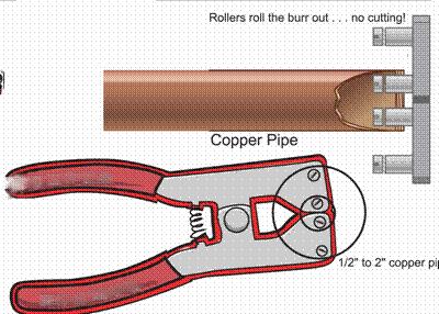
42 Item #: 179 UPC ( ): SUBMITTER: Joseph Kerze Gilbert, AZ RECOMMENDATION: Revise text as follows: Burred ends of all tubing shall be rolled smooth with a chipless reamer or deburred using a deburring tool to the full bore of the tube, and all chips shall be removed. SUBSTANTIATION: Issues and concerns regarding the cut ends of tubing include the following: (1) All references to reaming in the current and past codes states or implies that the burr has to be cut out by removing material therefore forbidding new technologies or innovation in dealing with the problem of de-burring copper pipe that does not remove material. (2) Governing plumbing authorities not familiar with newer technologies for preparing the end of copper pipe for assembly may reject (and have rejected) the use of a tool that does not cut or remove the burr (traditional and stated process) [NFPA ] and UPC 2006 IS but re-forms or smoothes the burr to the full inside diameter of the pipe without removing material. (3) When a burr is removed from a copper pipe by cutting it with a blade type reamer, sharp chips and debris (down to the microscopic level) are created. The chips may become lodged in valves or other devises causing problems or if ingested or inhaled by the end user a health hazard may occur. A chipless reamer reforms the burr without removing material therefore debris is not produced in the process. This may be useful in addressing UPC and NFPA (field contamination of pipe). (4) A sharp clean deburring tool used to ream the tube has sharp surfaces that have the potential to cut or injure the installer particularly if the plumber is in a hurry. A chipless reamer has no sharp edges and prepares the copper pipe in less time than the tools mentioned in the current code therefore decreasing the chance of injury and saving time in the process. (5) When reaming installed hard drawn in the vertical position with a blade reamer most of the chips and debris cut from the pipe falls down the tubing contaminating the system. A chipless reamer does not produce debris in the process of meeting the installation standard of. [NFPA ] (See image on page 196 1) 196
43
44 Item #: 180 UPC ( ): SUBMITTER: Theodore C. Lemoff NFPA International RECOMMENDATION: Revise text as follows: Branch connections in vacuum piping systems shall be permitted to be made using mechanically formed, drilled, and extruded tee branch connections that are formed in accordance with the tool manufacturer's instructions and brazed. [NFPA , , , (4)-(7)] SUBSTANTIATION: A reference to NFPA 99 is updated. This proposal is not original material; its reference/source is as follows: NFPA 99, Standard for Health Care Facilities 197
45 Item #: 181 UPC ( ): SUBMITTER: Theodore C. Lemoff NFPA International RECOMMENDATION: Revise text as follows: Where a positive-pressure medical gas piping distribution system, originally used or constructed for the use at one pressure and for one gas, is converted for operation at another pressure or for another gas, all provisions of NFPA shall apply as if the system were new. A vacuum system shall not be permitted to be converted for use as a gas system. [NFPA ]. SUBSTANTIATION: Reference to NFPA 99 is added, and the correct citation of a paragraph extracted from NFPA 99 is provided. This proposal is not original material; its reference/source is as follows: NFPA 99, Standard for Health Care Facilities 198
46 Item #: 182 UPC ( ): SUBMITTER: Theodore C. Lemoff NFPA International RECOMMENDATION: Revise text as follows: Piping shall be supported from the building structure in accordance with MSS Standard Practice SP-69, Piping Hangers and Supports Selection and Application. Hangers and supports shall comply with MSS Standard Practice SP-58, Pipe Hangers and Supports Materials, Design, and Manufacture. Hangers for copper tube shall have a copper finish and be sized for copper tube. In potentially damp locations, copper tube hangers or supports that are in contact with the tube shall be plastic-coated or otherwise be insulated from the tube. Maximum support spacing shall be in accordance with Table [NFPA 99 Table ] SUBSTANTIATION: Correct citation is provided for an extract from NFPA 99 This proposal is not original material; its reference/source is as follows: NFPA 99, Standard for Health Care Facilities 199
47 Item #: 183 UPC ( ): SUBMITTER: Joseph Kerze Gilbert, AZ RECOMMENDATION: Revise text as follows: Tube ends shall be cut square using a sharp tubing cutter to avoid deforming the tube. [NFPA ] The cutting wheels on tubing cutters shall be free from grease, oil, or other lubricant not suitable for oxygen service. [NFPA ] The cut ends of the tube shall be rolled smooth with a chipless reamer to the full diameter of the tube or deburred with a sharp, clean deburring tool, taking care to prevent chips from entering the tube. [NFPA ] SUBSTANTIATION: Issues and concerns regarding the cut ends of tubing include the following: (1) All references to reaming in the current and past codes states or implies that the burr has to be cut out by removing material therefore forbidding new technologies or innovation in dealing with the problem of de-burring copper pipe that does not remove material. (2) Governing plumbing authorities not familiar with newer technologies for preparing the end of copper pipe for assembly may reject (and have rejected) the use of a tool that does not cut or remove the burr (traditional and stated process) [NFPA ] and UPC 2006 IS but re-forms or smoothes the burr to the full inside diameter of the pipe without removing material. (3) When a burr is removed from a copper pipe by cutting it with a blade type reamer, sharp chips and debris (down to the microscopic level) are created. The chips may become lodged in valves or other devises causing problems or if ingested or inhaled by the end user a health hazard may occur. A chipless reamer reforms the burr without removing material therefore debris is not produced in the process. This may be useful in addressing UPC and NFPA (field contamination of pipe) (4) A sharp clean deburring tool used to ream the tube has sharp surfaces that have the potential to cut or injure the installer particularly if the plumber is in a hurry. A chipless reamer has no sharp edges and prepares the copper pipe in less time than the tools mentioned in the current code therefore decreasing the chance of injury and saving time in the process. (5) When reaming installed hard drawn in the vertical position with a blade reamer most of the chips and debris cut from the pipe falls down the tubing contaminating the system. A chipless reamer does not produce debris in the process of meeting the installation standard of [NFPA ] (See image on page 200 1) 200
48
49 Item #: 184 UPC ( (2) ): SUBMITTER: Guy Wayne Harrison Josam Company RECOMMENDATION: Revise text as follows: Tubes shall be hard-drawn seamless copper ASTM B 819 medical gas tube, Type L, except that where operating pressures are above a gauge pressure of 1,275 kpa (185 psi), Type K shall be used for sizes larger than DN80 (NPS 3) (3 1/8 in. O.D.). ASTM B 819 medical gas tube shall be identified by the manufacturer's markings "OXY," "MED," "OXY/MED," "OXY/ACR," or "ACR/MED" in blue (Type L) or green (Type K). Piping for vacuum systems shall be constructed of any of the following: (1) Hard-drawn seamless copper tube (a) ASTM B 88, Standard Specification for Seamless Copper Water Tube, copper tube (Types K, L, M). (b) ASTM B 280, Standard Specification for Seamless Copper Tubing for Air Conditioning and Refrigeration Field Service, copper ACR tube. (c) ASTM B 819, Standard Specification for Seamless Copper Tube for Medical Gas Systems, copper medical (2) Stainless steel tube (a) ASME A (Remainder of text not shown do not change) SUBSTANTIATION: Stainless steel is referenced without a referenced standard for vacuum systems. ASME is currently referenced in Table 14 1 of this code. This proposal is not original material; its reference/source is as follows: ASME A (2005) 201
50
51 Item #: 185 UPC ( ): SUBMITTER: Guy Wayne Harrison Josam Company RECOMMENDATION: Revise text as follows: Piping between vacuum pumps, discharges, receivers, and the vacuum main line valve shall be in accordance with Section , except that stainless steel, or steel pipe shall be permitted to be either black or galvanized. [NFPA (5)] SUBSTANTIATION: As outlined in the NFPA 99C-2005 for Gas and Vacuum Systems in Chapter 13-NFPA document submitted under Section (5). See attached NFPA 99C (5) This proposal is not original material; its reference/source is as follows: NFPA 99C
52 Item #: 186 UPC ( ): SUBMITTER: Krista Braaksma Washington State Building Code Council RECOMMENDATION: Revise text as follows: System Certification Verification. SUBSTANTIATION: This proposal is for consistency in terms. The standard provides for medical gas system verification rather than certification. This proposal is not original material; its reference/source is as follows: This is an existing Washington State Uniform Plumbing Code Amendment developed through our Technical Advisory Group. 203
53 Item #: 187 UPC (Chapter 14, Table 14 1 (New)): SUBMITTER: Dave Viola Chair, UPC Standards Task Group RECOMMENDATION: The following is recommended by the Standards Task Group (see Standards Task Group Report Item #187) Delete Table 14 1 and Table 14 1 Index. Substitute as follows: (See attached Table Chapter 14 Mandatory Referenced Standards Table 14 1 on page through ) SUBSTANTIATION: The standards task group was charged by the UPC Technical Committee to add cross-references to Table 14 1 where such sections are applicable to the referenced standards and to update the format of standards referencing materials and products. In addition, to update referenced standards and provide editorial revisions to Table
54 Delete Table 14-1 and Table 14-1 Index. Substitute as follows: Item # 187 THE SCOPE OF THE STANDARDS TASK GROUP INCLUDES ADDING CROSS-REFERENCES TO TABLE 14 1 AND RECOMMEND WHERE SUCH REFERENCES ARE APPLICABLE TO THE REFERENCED STANDARDS AND TO UPDATE THE FORMAT OF STANDARDS REFERENCING MATERIALS AND PRODUCTS. THE RECOMMENDED PROPOSED CODE CHANGES WERE PLACED IN THE MONGRAPH BASED ON NUMERICAL ORDER ABOING WITH THE ITEM NUMBER AS SHOWN NEXT TO THE PROPOSALS. THE FOLLOWING ARE RECOMMENDATIONS FROM THE STANDARDS TASK GROUP. CHAPTER 14 MANDATORY REFERENCED STANDARDS TABLE 14 1 Standards for Materials, Equipment, Joints and Connections Where more than one standard has been listed for the same meterail or method, the relevant portions of all such standards shall apply. Standard Number Standard Title Application Referenced Sections AHAM DW * Household Electric Dishwashers Appliances 401.1, AHAM DW-2PR-92 Plumbing Requirements for Household Dishwashers (Discontinued) Appliances AHAM FWD Food Waste Disposer Units Appliances 401.1, 404.4, AHAM FWD-2PR-89 Household Food Waste Disposer Units (Discontinued) Appliances ANSI A Ductile-Iron and Gray-Iron Fittings, 3 in. through 48 in. (75 mm through 1,200 mm), for Water and Other Liquids (same as AWWA C110) Piping, Ferrous
55 Delete Table 14-1 and Table 14-1 Index. Substitute as follows: Item # 187 ANSI A Rubber-Gasket Joints for Ductile-Iron Pressure Pipe and Fittings (same as AWWA C111) Piping, Ferrous ANSI A Ductile-Iron Pipe, Centrifugally Cast, for Water (same as AWWA C151) Piping, Ferrous ANSI A Ductile-Iron Compact Fittings, 3 in. through 24 in. (76 mm through 610 mm) and 54 in. through 64 in. (1400 mm through 1600 mm), for Water Service (same as AWWA C153) Piping, Ferrous ANSI B Pipe Threads (Except Dry seal) (replaced by ASME B ) Joints ARI Drinking Fountains and Self-Contained, Mechanically Refrigerated Drinking Water Coolers (Offically Withdrawn) Fixture ASCE Earthquake Actuated Automatic Gas Shutoff Devices Fuel Gas 1201 ASHRAE * Energy Standard for Buildings Except Low-Rise Residential Buildings Miscellaneous 501 ANSI ASME A (R03) * Scheme for the Identification of Piping Systems Piping ASME A Air Gaps in Plumbing Systems Fittings Table 6-2, Table 6-3, ASME A (R05) * Air Gap Fittings for Use with Plumbing Fixtures, Appliances, and Appurtenances Fixtures Table 6-2, , 801.1, 806.0, 807.4
56 Delete Table 14-1 and Table 14-1 Index. Substitute as follows: Item # 187 ASME A Performance Standard and Installation Procedures for Stainless Steel Drainage Systems for Sanitary, Storm, and Chemical Applications, Above and Below Ground (Note 1) Piping, Ferrous 701.1, 701.2, 707.1, Table 7-1 ASME A (R04) * Macerating Toilet Systems and Related Components Fixtures ASME A (R02) Water Heater Relief Valve Drain Tubes Appliances ASME A Water Closet Personal Hygiene Devices Fixtures ASME A (R04) Plastic Fittings for Connecting Water Closets to the Sanitary Drainage System Piping ASME A * Point of Use and Branch Water Submetering Systems Miscellaneous 301 ASME A M-97 (R02) Floor-Affixed Supports for Off-the-Floor Plumbing Fixtures for Public Use Fixtures , ASME A (R04) Framing-Affixed Supports for Off-the-Floor Water Closets with Concealed Tanks Fixtures 316.3, ASME A Floor and Trench Drains DWV Components ASME A Roof, Deck, and Balcony Drains DWV Components
57 Delete Table 14-1 and Table 14-1 Index. Substitute as follows: Item # 187 ASME A Enameled and Epoxy Coated Cast Iron and PVC Plastic Sanitary Floor Sinks Fixtures Table 4-1 footnote (9), ASME A Backwater Valves Valves ASME A (R04) * Grease Interceptors Fixtures , ASME A * Grease Removal Devices Fixtures ASME A / CSA B Plumbing Supply Fittings Fixtures Fittings , ASME A / CSA B Plumbing Waste Fittings Fittings 404.3, 701.0, ASME A * Performance Requirements for Backflow Protection Devices and Systems in Plumbing Fixtures Fittings Kitchen, Lavatory, shampoobowls, and Shower Fittings with Flexible Hose , ASME A Flexible Water Connectors Piping , 604.4, , ASME A (R04) Deck Mounted Bath/Shower Transfer Valves with Integral Backflow Protection Valves , ASME A M-94 (R04) Enameled Cast-Iron Plumbing Fixtures (Supplement ) Fixtures 401.1, 411.5, 411.6, 411.7, 414.0
58 Delete Table 14-1 and Table 14-1 Index. Substitute as follows: Item # 187 ASME A M * Vitreous China Plumbing Fixtures and Hydraulic Fixtures Requirements for Water Closets and Urinals Fixtures 401.1, 402.1, 402.2, 402.3, 408.0, 410.0, 410.4, 413.0, ASME A M (R04) * Stainless Steel Plumbing Fixtures (Designed for Residential Use) Fixtures ASME A M-94 (R04) * Porcelain-Enameled Formed Steel Plumbing Fixtures (Supplement ) Fixtures 401.1, 411.5, 411.6, 411.7, ASME A Trim for Water-Closet Bowls, Tanks, and Urinals Fixtures ASME A M * Whirlpool Hydromassage Bathtub Appliances Fixtures 401.1, ASME A M-87 (R96)(R05) * Suction Fittings for Use in Swimming Pools, Wading Pools, Spas, Hot Tubs, and Whirlpool Bathtub Appliances Swimming Pools and Spas ASME A M-91 (R02) * Non-Vitreous Ceramic Plumbing Fixtures Fixtures 401.1, 408, 410.4, ASME A * Dual Flush Devices for Water Closets Fixtures ASME A * Wall Mounted and Pedestal Mounted Adjustable Elevating, Tilting and Pivoting Lavatory, and Sink and Shampoo Bowl Carrier Systems and Drainage Waste Systems Fixtures 401.1, ASME A * Electrohydraulic Water Closets Fixtures 401.1, 408.0, 410.4
59 Delete Table 14-1 and Table 14-1 Index. Substitute as follows: Item # 187 ASME A * Six-Liter Water Closets Equipped with a Dual Flushing Device Fixtures 410.1, 401.1, ASME A * Bathtub/Whirlpool Bathtubs with Pressure Sealed Doors Fixtures ASME A Qualification of Installers of High Purity Piping Systems Certification ASME A Qualification of Installers of Firestop Systems and Devices for Piping Systems Certification ASME A M-85 (R01) * Hydrants for Utility and Maintenance Use (Note 1) Valves ASME A M-91 (R02) * Cleanouts (Note 1) DWV Components ASME B (R01 R06) * Pipe Threads, General Purpose, Inch Joints (2), , (A) ASME B (R03) * Dryseal Pipe Threads, Inch Joints ASME B Cast Iron Pipe Flanges and Flanged Fittings (Classes 25, 125, 250) and 800 Piping, Ferrous Table 6-4, 604.5, , , (5) ASME B * Malleable-Iron Threaded Fittings Classes 150 and 300 Piping, Ferrous 311.8, Table 6-4, 604.1, 604.6, Table 7-1, 701.2, , , (2)
60 Delete Table 14-1 and Table 14-1 Index. Substitute as follows: Item # 187 ASME B Gray Iron Threaded Fittings, Classes 125 and 250 (Includes Revision Services) Piping, Ferrous 311.8, 604.5, 604.1,Table 6-4, 604.1, (2) ASME B Pipe Flanges and Flanged Fittings: NPS 1/2 through 24 Joints ASME B (R06) * Cast Iron Threaded Drainage Fittings (Note 1) Piping, Ferrous 311.8, Table 7-1, ASME B (R04) * Cast Bronze Threaded Fittings, Classes 125 and 250 Piping, Copper Alloy 311.8, , Table 6-4, ASME B Cast Copper Alloy Solder Joint Pressure Fittings (Note 1) Piping, Copper Alloy , Table 6-4, ASME B * Standard for ring-joint gaskets and grooves for steel pipe flanges Metallic Gaskets For Pipe Flanges: Ring Joint Spiral Wound And Jacketed Table 6-4, , , ASME B * Nonmetallic Flat Gaskets for Pipe Flanges Joints , ASME B (R05) * Wrought Copper and Copper Alloy Solder Joint Pressure Fittings Alloy Piping, Copper Alloy , Table 6-4, 604.1, , , ASME B * Cast Copper Alloy Solder Joint Drainage Fittings DWV Piping, Copper Alloy , Table 7-1, 701.2, , ASME B * Cast Copper Alloy Pipe Flanges and Flanged Fittings: Classes 150,300, 400, 600, 900, 1500 and 2500 Piping, Copper Alloy Table 6-4, 604.1, ,
61 Delete Table 14-1 and Table 14-1 Index. Substitute as follows: Item # 187 ASME B * Cast Copper Alloy Fittings for Flared Copper Tubes Piping, Copper Alloy , Table 6-4, 604.1, ASME B * Wrought Copper and Wrought Copper Alloy Solder Joint Drainage Fittings DWV Alloy (Note 1) Piping, Copper Alloy , Table 7-1, 701.2, ASME B * Manually Operated Metallic Gas Valves for Use in Gas Piping Systems up to 125 psig (Sizes NPS 1/2 - NPS 24) Valves ASME B * Valves Flanged, Threaded, and Welding End Valves ASME B * Pipe Unions, Malleable Iron Threaded Pipe Unions (Classes 150, 250 and 300) (Includes Revision Services) Piping, Ferrous (4) ASME B * Manually Operated Thermoplastic Gas Shutoff and Valves in Gas Distribution Systems Fuel Gas , ASME B Large Diameter Steel Flanges Piping, Ferrous ASME B * Wrought Copper and Copper Alloy Braze-Joint Pressure Fittings Piping, Copper Alloy Table 6-4, ASME B Power Piping Piping ASME B36.10M-2004 * Welded and Seamless Wrought Steel Pipe Piping, Ferrous
62 Delete Table 14-1 and Table 14-1 Index. Substitute as follows: Item # 187 ASME B36.19M * Stainless Steel Pipe Piping, Ferrous ASME Section IV Rules for Construction of Heating Boilers Miscellaneous ASME Section VIII Rules for Construction of Pressure Vessels Miscellaneous (2), ASME Section IX Welding and Brazing Procedures, Welders, Braziers, and Welding and Brazing Operators Qualifications Certification , 506.4, , ASSE * Atmospheric-Type Vacuum Breakers Backflow Protection Table 6-2, 603.1, , , , , , ASSE Anti-Siphon Fill Valves (Ballcocks) for Gravity Water Closet Flush Tank Backflow Protection Table 6-2, 603.1, ASSE * Water Pressure Reducing Valves Valves ASSE Backflow Prevention Requirements for Commercial Dishwashing Machines Backflow Protection , , , ASSE Water Heater Drain Valves (Withdrawn) Valves ASSE Residential Use Dishwashers Appliances , , 807.4
63 Delete Table 14-1 and Table 14-1 Index. Substitute as follows: Item # 187 ASSE Home Laundry Equipment Appliances , ASSE * Plumbing Aspects of Food Waste Disposer Units Appliances , , ASSE Commercial Food Waste Grinder Units Appliances , ASSE * Water Hammer Arresters Piping , ASSE * Hose-Connection Vacuum Breakers Backflow Protection 603.1, ASSE * Backflow Prevention with Intermediate Atmospheric Vent Backflow Protection ASSE * Reduced Pressure Principle Backflow Preventers and Reduced Pressure Fire Protection Principle Backflow Preventers Backflow Protection Table 6-2, 603.1, , , , , , , , , ASSE * Backflow Prevention Devices for Hand-Held Showers Backflow Pretection ASSE * Double-Check Backflow Prevention Assemblies and Double Check Fire Protection Backflow Prevention Assemblies Backflow Protection Table 6-2, 603.1, , , , ASSE * Automatic Compensating Valves for Individual Showers and Tub/Shower Combinations Valves 418.0
64 Delete Table 14-1 and Table 14-1 Index. Substitute as follows: Item # 187 ASSE * Temperature Actuated Mixing Valves for Hot Water Distribution Systems Valves ASSE * Trap Seal Primer Valves-Potable Water Supplied Valves ASSE * Vacuum Breaker Wall Hydrant, Freeze-Resistant Automatic Draining Type Backflow Protection Table 6-2, ASSE * Pressure Vacuum Breaker Assembly Backflow Protection Table 6-2, , , , , ASSE Drains Air Gaps for Domestic Dishwasher Applications Backflow Protection ASSE * Backflow Preventer for Beverage Dispensing Equipment Backflow Protection Table 6-2, ASSE Hot Water Dispensers, Household Storage Type-Electrical Appliances ASSE * Dual Check Valve Backflow Preventers Backflow Prevention ASSE Diverters for Plumbing Faucets with Hose Spray, Anti-Siphon Type, Residential Applications (Deleted no longer in publication) Valves ASSE Dual Check Valve Type Backflow Preventers for Carbonated Beverage Dispensers Post Mix Types Backflow Protection 603.1
65 Delete Table 14-1 and Table 14-1 Index. Substitute as follows: Item # 187 ASSE * Laboratory Faucet Backflow Preventers Backflow Protection ASSE Pressurized Flushing Devices (Flushometers) for Plumbing Fixtures Backflow Protection ASSE * Trap Seal Primer Devices-Drainage Types and Electronic Design Types DWV Components ASSE * Reduced Pressure Detector Fire Protection Backflow Prevention Assemblies Backflow Protection Table 6-2, , , ASSE * Double Check Detector Fire Protection Backflow Prevention Assemblies Backflow Protection Table 6-2, ASSE * Hose Connection Backflow Preventers Backflow Protection ASSE Chemical Dispensing Systems Backflow Protection ASSE * Spill Resistant Vacuum Breakers Backflow Protection Table 6-2, , , , ASSE * Temperature Actuated Flow Reduction (TAFR) Valves for Individual Fixture Fittings Valves ASSE Individual Pressure Balancing In-Line Valves for Individual Fixture Fittings (Note 9) Valves
66 Delete Table 14-1 and Table 14-1 Index. Substitute as follows: Item # 187 ASSE * Automatic Temperature Control Mixing Valves Valves ASSE * Water Temperature Limiting Devices Valves 413.1, ASSE Series * Professional Qualification Standard for Backflow Prevention Assemblies Testers, Repairers, and Surveyors Certification 603.1, ASSE * Professional Qualifications Standard for Medical Gas Systems Installers, Inspectors, and Verifiers, Maintenance Personnel and Instructors Certification AHAM ASSE DW-2PR-92 Plumbing Requirements for Household Dishwashers Appliances Table 7-3, AHAM ASSE FWD-2 PR-89 Household Food Waste Disposer Units Appliances 401.1, ASTM A (R04) Ferritic Malleable Iron Castings Piping, Ferrous ASTM A Gray Iron Castings Piping, Ferrous ASTM A a Pipe, Steel, Black and Hot-Dipped, Zinc-Coated, Welded, and Seamless Piping, Ferrous Table 6-4, 604.1, ASTM A Cast-Iron Soil Pipe and Fittings (Note 1) Piping, Ferrous Table 7-1, 701.1, 701.2, 807.3, 903.1, , , , ,
67 Delete Table 14-1 and Table 14-1 Index. Substitute as follows: Item # 187 ASTM A Gray Iron Castings for Valves, Flanges, and Pipe Fittings Piping, Ferrous 311.8, , ASTM A 197M-2000 (R06) Cupola Malleable Iron (Metric) Piping, Ferrous 311.8, , ASTM A Seamless and Welded Austenitic Stainless Steel Tubing for General Service Piping, Ferrous ASTM A 312M-2004b 2006 Seamless, Welded and Heavy Cold Worked Austenitic Stainless Steel Pipes Piping, Ferrous ASTM A Ductile-Iron Pressure Pipe Piping, Ferrous ASTM A 479M a Stainless Steel Bars and Shapes for Use in Boilers and Other Pressure Vessels Piping, Ferrous ASTM A (R03) Corrosion-Resistant High-Silicon Iron Castings Piping, Ferrous ASTM A (R04) Ductile Iron Castings Piping, Ferrous ASTM A 653M-2004a 2006 Steel Sheet, Zinc-Coated (Galvanized) or Zinc-Iron Alloy-Coated (Galvannealed) by the Hot-Dip Process Piping, Ferrous 313.8, , , 906.1, ASTM A Welded and Seamless Carbon Steel and Austenitic Stainless Steel Pipe Nipples Piping, Ferrous 604.1
68 Delete Table 14-1 and Table 14-1 Index. Substitute as follows: Item # 187 ASTM A High-Silicon Iron Pipe and Fittings (Note 1) Piping, Ferrous 811.1, ASTM A a 2007 Hubless Cast-Iron Soil Pipe and Fittings for Sanitary and Storm Drain Waste and Vent Piping Applications Piping, Ferrous Table 7-1, 701.1, 701.2, 807.3, 903.1, 903.3, , , ASTM B Refined Lead Joints 701.3, , 906.6, 313.8, 401.2, 411.8, , ASTM B Solder Metal (Note 4) Joints , ASTM B e1 Seamless Copper Pipe, Standard Sizes Piping, Copper Alloy Table 6-4, 604.1, , ASTM B 43-98(R04) Seamless Red Brass Pipe, Standard Sizes Piping, Copper Alloy Table 6-4, 604.1, Table 7-1, 701.1, , ASTM B Seamless Copper Tube Piping, Copper Alloy Table 6-4, 604.1, 701.1, , , ASTM B Seamless Copper Water Tube Piping, Copper Alloy Table 6-4, 604.1, , , , , ASTM B Seamless Brass Tube (Metric) Piping, Copper Alloy 301.2, Table 6-4, ASTM B 152M a Copper Sheet, Strip, Plate, and Rolled Bar Miscellaneous
69 Delete Table 14-1 and Table 14-1 Index. Substitute as follows: Item # 187 ASTM B e1 General Requirements for Wrought Seamless Copper Copper-Alloy Tube Piping, Copper Alloy 302.0, 316.1, Table 6-4, 604.1, Table 7-1, 701.1, , ASTM B Seamless Copper Tube for Air Conditioning and Refrigeration Field Service Piping, Copper Alloy , , ASTM B Threadless Copper Pipe, Standard Sizes Piping, Copper Alloy 301.2, Table 6-4, 604.1, Table 7-1, ASTM B Copper Drainage Tube (DWV) Piping, Copper Alloy ASTM B Copper Sheet and Strip for Building Construction Miscellaneous ASTM B Welded Copper Tube Piping, Copper Alloy 301.2, Table 6-4, ASTM B a Copper Alloy Sand Casting for General Applications (Note 5) Piping, Copper Alloy , , , ASTM B e1 (R03) 2006 Welded Brass Tube Piping, Copper Alloy ASTM B (R05)e1 Brass, Copper, and Chromium-Plated Pipe Nipples Piping, Copper Alloy ASTM B e1 Liquid and Paste Fluxes for Soldering Applications of Copper and Copper Alloy Tube Joints
70 Delete Table 14-1 and Table 14-1 Index. Substitute as follows: Item # 187 ASTM B (R06) Seamless Copper Tube for Medical Gas Systems Piping, Copper Alloy , , ASTM B Making Capillary Joints by Soldering of Copper and Copper Alloy Tube and Fittings Joints ASTM C a Nonreinforced Concrete Sewer, Storm Drain, and Culvert Pipe Piping, Non- Metallic Table 7-1, 701.1, ASTM C (R04)e1 Asbestos-Cement Pressure Pipe Piping, Non- Metallic Table 6-4, ASTM C a Concrete Drain Tile Piping, Non- Metallic ASTM C Compression Joints for Vitrified Clay Pipe and Fittings Joints ASTM C (R02) e1 2005(R06) Asbestos-Cement Nonpressure Sewer Pipe (Notes 6 and 7) Piping, Non- Metallic Table 7-1, 701.1, , 715.0, ASTM C a Joints for Circular Concrete Sewer and Culvert Pipe and Manholes, Using Rubber Gaskets Joints ASTM C a 2006a Precast Reinforced Concrete Manhole Sections Miscellaneous ASTM C a Rubber Gaskets for Cast-Iron Soil Pipe and Fittings Joints
71 Delete Table 14-1 and Table 14-1 Index. Substitute as follows: Item # 187 ASTM C Vitrified Clay Pipe, Extra Strength, Standard Strength, and Perforated Piping, Non- Metallic Table 7-1, 701.1, 701.2, ASTM C (R05) Borosilicate Glass Pipe and Fittings for Drain, Waste, and Vent (DWV) Applications (Note 1) Piping, Non- Metallic ASTM C Flexible Transition Couplings for Underground Piping Systems Joints , ASTM C Shielded Couplings Joining Hubless Cast-Iron Soil Pipe and Fittings Piping, Ferrous Joints , ASTM C Thermoplastic Elastomeric (TPE) Gasket Materials for Drain, Waste, and Vent (DWV), Sewer, Sanitary and Storm Plumbing Systems Piping, Plastic Joints , ASTM C Shielded Transition Couplings for Use with Dissimilar DWV Pipe and Fittings Above Ground Piping, Plastic Joints , ASTM C Mechanical Couplings Using Thermoplastic Elastomeric (TPE) Gaskets for Joining Drain, Waste, and Vent (DWV); Sewer; Sanitary; and Storm Piping, Plastic Joints , , , , Plumbing Systems for Above and Below Ground Use ASTM C Heavy Duty Shielded Couplings Joining Hubless Cast Iron Soil Pipe and Fittings Joints , ASTM D e1 (R05) * Acrylonitrile-Butadiene-Styrene (ABS) Plastic Pipe, Sch. 40 and 80 Piping, Plastic Table 3-2, , ASTM D Rigid Poly (Vinyl Chloride) (PVC) Compounds and Chlorinated Poly (Vinyl Chloride) (CPVC) Compounds Piping, Plastic Miscellaneous 301.2
72 Delete Table 14-1 and Table 14-1 Index. Substitute as follows: Item # 187 ASTM D a 2006 * Poly (Vinyl Chloride) (PVC) Plastic Pipe, Schedules 40, 80, and 120 Piping, Plastic Table 3-2, Table 6-4, 604.1, Table 7-1, 701.1, 903.1, , , ASTM D (R00) (R05) Rubber O-rings for Asbestos-Cement Pipe Joints ASTM D * Polyethylene (PE) Plastic Pipe, Sch. 40 Piping, Plastic ASTM D * Solvent Cement for Acrylonitrile-Butadiene-Styrene (ABS) Plastic Pipe and Fittings Joints ASTM D * Polyethylene (PE) Plastic Pipe, (SDR-PR) Based on Controlled Inside Diameter Piping, Plastic 604.1, Table 6-4 ASTM D b 2005 * Poly(Vinyl Chloride)(PVC) Pressure-Rated Pipe (SDR Series) Piping, Plastic 604.1, Table 6-4 ASTM D e1 (R05) * Acrylonitrile-Butadiene-Styrene (ABS) Plastic Pipe (SDR-PR) Piping, Plastic ASTM D * Underground Installation of Thermoplastic Pipe for Sewers and Other Gravity-Flow Applications Piping, Plastic ASTM D * Polyethylene (PE) Plastic Pipe, Sch. 40 and 80 (Based on Controlled Outside Diameter) Piping, Plastic ASTM D e * Threaded Poly(Vinyl Chloride) (PVC) Plastic Pipe Fittings, Sch. 80 (Note 1) Piping, Plastic Table 6-4, 604.1
73 Delete Table 14-1 and Table 14-1 Index. Substitute as follows: Item # 187 ASTM D * Poly(Vinyl Chloride) (PVC) Plastic Pipe Fittings, Sch. 40 (Note 1) Piping, Plastic Table 6-4, ASTM D e * Poly(Vinyl Chloride) (PVC) Plastic Pipe Fittings, Sch, 80 (Note 1) Piping, Plastic Table 6-4, ASTM D a 2006a * Thermoplastic Gas Pressure Pipe Tubing and Fittings (Note 1) Piping, Plastic , , , (B), ASTM D e * Reinforced Epoxy Resin Gas Pressure Pipe and Fittings Piping, Plastic ASTM D e1 * Solvent Cements for Poly(Vinyl Chloride) (PVC) Plastic Piping Systems Joints , Table 6-4, ASTM D * Plastic Insert Fittings for Polyethylene (PE) Plastic Pipe (Note 1) Piping, Plastic Table 6-4, ASTM D * Practice for Heating Fusion Joining of Polyolefin Pipe Fittings (Note 1) Joints ASTM D * Acrylonitrile-Butadiene-Styrene (ABS) Sch. 40 Plastic Drain, Waste, and Vent Pipe and Fittings (Note 1) Piping, Plastic Table 7-1, 701.1, 701.2, , 707.1, 903.1, 903.3, ASTM D a (e2) * Poly(Vinyl Chloride) (PVC) Plastic Drain, Waste, and Vent Pipe and Fittings (Note 1) Piping, Plastic Table 7-1, 701.1, 701.2, , 707.1, 903.1, 903.3, , ASTM D a (R03) * Joints for IPS PVC Pipe Using Solvent Cement Joints
74 Delete Table 14-1 and Table 14-1 Index. Substitute as follows: Item # 187 ASTM D * Acrylonitrile-Butadiene-Styrene (ABS) and Poly(Vinyl Chloride) (PVC) Composite Sewer Piping Piping, Plastic Table 7-1, 701.1, , 715.0, ASTM D * Poly(Vinyl Chloride) (PVC) Sewer Pipe and Fittings (Note 1) Piping, Plastic , ASTM D * Polyethylene (PE) Plastic Tubing Piping, Plastic Table 6-4, ASTM D a 2005 * Acrylonitrile-Butadiene-Styrene (ABS) Sewer Pipe and Fittings (Note 1) Piping, Plastic , ASTM D e * Chlorinated Poly (Vinyl Chloride) (CPVC) Plastic Hot- and Cold-Water Piping, Plastic , Table 6-4, Distribution Systems ASTM D (R02) * Making Solvent-Cemented Joints with Poly(Vinyl Chloride) (PVC) Pipe and Fittings Joints ASTM D * Filament-Wound Fiberglass (Glass-Fiber-Reinforced Thermosetting Resin) Pipe Piping, Plastic ASTM D a 2006 * Type PSM Poly (Vinyl Chloride) (PVC) Sewer Pipe and Fittings Piping, Plastic , 715.0, ASTM D a * Polyethylene (PE) Plastic Pipe (DR-PR) (Based on Controlled Outside Diameter) Piping, Plastic Table 6-4, ASTM D (R02) * Solvent Cements for Styrene-Rubber (SR) Plastic Pipe and Fittings Joints 301.2
75 Delete Table 14-1 and Table 14-1 Index. Substitute as follows: Item # 187 ASTM D * Solvent Cements for Transition Joints, Acrylonitrile-Butadiene- Styrene (ABS) and Poly (Vinyl Chloride) (PVC) Non-Pressure Piping Components Joints ASTM D (R05) * Joints for Plastic Pressure Pipes Using Flexible Elastomeric Seals Joints ASTM D a (R03) e1 * Joints for Drain and Sewer Plastic Pipes Using Flexible Elastomeric Seals Joints ASTM D e * Drain, Waste, and Vent (DWV) Plastic Fittings Patterns (Note 1) Piping, Plastic ASTM D * Rigid Acrylonitrile-Butadiene-Styrene (ABS) Materials for Pipe and Fittings Piping, Plastic Miscellaneous 311.8, , , 701.1, , 701.2, , , 707.1, 903.1, , 903.3, , , , ASTM D * Chlorinated Polyethylene (CPE) Sheeting for Concealed Water- Containment Membrane Fixtures 411.8(2) ASTM D a 2006a * Propylene Plastic Polypropylene Injection and Extrusion Materials Miscellaneous 811.1, ASTM D (R01) * Poly(Vinyl Chloride) (PVC) Plastic Flexible Concealed Water- Containment Membrane Fixtures 411.5, ASTM D (R03) Determining the Performance of Oil/Water Separators Subjected to Surface Run-Off Fixtures , ASTM E Surface Burning Characteristics of Building Materials Miscellaneous , ,
76 Delete Table 14-1 and Table 14-1 Index. Substitute as follows: Item # 187 ASTM E a 2005a Fire Tests of Building Construction and Materials Miscellaneous 301.2, 301.4, 502.6, , , , ASTM E Fire Tests of Through-Penetration Fire Stops Miscellaneous 313.7, , , , , , , , ASTM F (R99) 2005 * Safe Handling of Solvent Cements, Primers, and Cleaners Used for Joining Thermoplastic Pipe and Fittings Joints ASTM F * Corrugated Polyethylene (PE) Tubing Pipe and Fittings Piping, Plastic ASTM F * Thermoplastic Accessible and Replaceable Plastic Tube and Tubular Fittings (Note 1) Piping, Plastic 1003 ASTM F * Threaded Chlorinated Poly(Vinyl Chloride) (CPVC) Plastic Pipe Fittings, Sch. 80 Piping, Plastic Table 6-4, ASTM F * Socket-Type Chlorinated Poly(Vinyl Chloride) (CPVC) Plastic Pipe Fittings, Sch. 40 Piping, Plastic ASTM F e * Socket-Type Chlorinated Poly(Vinyl Chloride) (CPVC) Plastic Pipe Fittings, Sch. 80 Piping, Plastic Table 6-4, ASTM F * Chlorinated Poly(Vinyl Chloride) (CPVC) Plastic Pipe, Sch. 40 and 80 Piping, Plastic Table 6-4, ASTM F (R05) * Chlorinated Poly(Vinyl Chloride) (CPVC) Plastic Pipe (SDR-PR) Piping, Plastic 604.1
77 Delete Table 14-1 and Table 14-1 Index. Substitute as follows: Item # 187 ASTM F b * Thermoplastic Well Casing Pipe and Couplings Made in Standard Dimension Ratios (SDR) Schedule 40 and Schedule 80 Piping, Plastic ASTM F * Solvent Cements for Chlorinated Poly (Vinyl Chloride) (CPVC) Plastic Pipe and Fittings Joints ASTM F * Acrylonitrile-Butadiene-Styrene (ABS) Sch. 40 Plastic Drain, Waste, and Vent Pipe with a Cellular Core, (Note 1) Piping, Plastic Table 7-1, 701.1, 701.2, , 707.1, 903.1, 903.3, ASTM F * Primers for Use in Solvent Cement Joints of Poly (Vinyl Chloride) (PVC) Plastic Pipe and Fittings Joints ASTM F * Large Diameter Corrugated Polyethylene Tubing Pipe and Fittings Piping, Plastic ASTM F * Polyethylene (PE) Plastic Pipe (SDR-PR) (Based on Outside Diameter) Piping, Plastic 715 ASTM F Type PS-46 and Type PS-115 Poly (Vinyl Chloride) (PVC) Plastic Gravity Flow Sewer Pipe and Fittings (Note 1) Officially withdrawn no Piping, Plastic replacement ASTM F * Poly (Vinyl Chloride) (PVC) Profile Gravity Sewer Pipe and Fittings Based on Controlled Inside Diameter Piping, Plastic Table 7-1, 701.1, 701.2, , 715.0, ASTM F * Smooth wall Polyethylene (PE) Pipe for Use in Drainage and Waste Disposal Absorption Fields Piping, Plastic ASTM F a 2005 * Cross linked Polyethylene (PEX) Tubing Piping, Plastic Table 6-4, 604.1,
78 Delete Table 14-1 and Table 14-1 Index. Substitute as follows: Item # 187 ASTM F a 2005 * Cross linked Polyethylene (PEX) Plastic Hot- and Cold-Water Distribution Systems Piping, Plastic Table 6-4, ASTM F * Co extruded Poly (Vinyl Chloride) (PVC) Plastic Pipe with a Cellular Core Piping, Plastic Table 7-1, 701.1, , 707.1, 903.1, 903.3, ASTM F a 2005 * Polyethylene (PE) Large Diameter Profile Wall Sewer and Drain Pipe Piping, Plastic ASTM F a * Poly (Vinyl Chloride) (PVC) Corrugated Sewer Pipe with a Smooth Interior and Fittings Piping, Plastic ASTM F * Rehabilitation of Existing Pipelines and Conduits by the Inversion and Curing of a Resin-Impregnated Tube Piping, Plastic ASTM F * Cross linked Polyethylene/Aluminum/Cross linked Polyethylene (PEX- AL-PEX) Pressure Pipe Piping, Plastic Table 6-4, 604.1, ASTM F * Polyethylene/Aluminum/Polyethylene (PE-AL-PE) Composite Pressure Piping, Plastic Table 6-4, 604.1, Pipe ASTM F e1 * Polyolefin Pipe and Fittings for Corrosive Waste Drainage Systems Piping, Plastic ASTM F * Performance of Gasketed Mechanical Couplings for Use in Piping Application Joints ASTM F * Polyvinylidene Fluoride (PVDF) Corrosive Waste Drainage Systems Piping, Plastic 811.2
79 Delete Table 14-1 and Table 14-1 Index. Substitute as follows: Item # 187 ASTM F (R03) * Rehabilitation of Existing Pipelines and Conduits by Pulled-in-Place Installation of Cured-in-Place Thermosetting Resin Pipe (CIPP) Piping, Plastic ASTM F * Metal Insert Fittings with Utilizing Copper Crimp Ring for SDR 9 Cross linked Polyethylene (PEX) Tubing Piping, Plastic Table 6-4, 604.1, ASTM F * Poly (Vinyl Chloride) (PVC) Plastic Schedule 40 Drainage and DWV Fabricated Fittings, Schedule 40 Piping, Plastic Table 7-1, 701.1, 701.2, , , 903.3, ASTM F e * Plastic Mechanical Fitting for Use on Outside Diameter Controlled Polyethylene Gas Distribution Pipe and Tubing Piping, Plastic ASTM F a e * Metallic Mechanical Fittings for Use on Outside Diameter Controlled Thermoplastic Gas Distribution Pipe and Tubing Piping, Plastic ASTM F * Cold Expansion Fittings with PEX Reinforcing Rings for Use with Cross-Linked Polyethylene (PEX) Tubing Piping, Plastic Table 6-4, 604.1, ASTM F a * Metal Metallic Cold Flare Compression Fittings with Disc Springs for Cross linked Polyethylene (PEX) Tubing Piping, Plastic Table 6-4, 604.1, ASTM F * Special Engineered Fittings or Appurtenances or Valves for Use in Poly(Vinyl Chloride) (PVC) or Chlorinated Poly (Vinyl Chloride) (CPVC) Systems Piping, Plastic 316.0, ASTM F * Factory Assembled Anodeless Riser and Transition Fitting in Polyethylene (PE) and Polymide 11 (PA11) Fuel Gas Distribution Systems Piping, Plastic ASTM F * Metal Insert Fittings for Polyethylene/Aluminum/Polyethylene and Crosslinked Polyethylene/Aluminum/Crosslinked Polyethylene Composite Pressure Pipe Piping, Plastic Table 6-4, 604.1,
80 Delete Table 14-1 and Table 14-1 Index. Substitute as follows: Item # 187 ASTM F Cold-Expansion Fittings With Metal Compression Sleeves for Cross- Linked Polyethylene (PEX) Pipe Piping, Plastic Table 6-4, 604.1, ASTM F e1 Stainless Steel Clamps for Securing SDR9 Cross-Linked Polyethylene (PEX) Tubing to Metal Insert Fittings Joints ASTM F Plastic Insert Fittings Utilizing a Copper Ring for SDR 9 Cross-Linked Polyethylene (PEX) Tubing Joints Table 6-4, 604.1, ASTM F * Flexible Pre-Insulated Piping Piping, Plastic ASTM F * Crosslinked Polyethylene/Aluminum/Crosslinked Polyethylene Tubing OD Controlled SDR 9 Piping, Plastic Table 6-4, 604.1, ASTM F Metal Insert Fittings Utilizing a Copper Crimp Ring for SDR9 Crosslinked Polyethylene (PEX) Tubing and SDR9 Crosslinked Polyethylene/Aluminum/Crosslinked Polyethylene (PEX-AL-PEX) Tubing Piping, Plastic Table 6-4, , AWS A * Specification for Filler Metals for Brazing and Braze Welding Joints AWS B Brazing Procedure and Performance Qualification Certification , AWWA C * Ductile-Iron and Gray-Iron Fittings, 3 in. through 48 in. (75 mm through 1200 mm), for Water and Other Liquids (same as ANSI A21.10-Piping, Ferrous Table 6-4, ) AWWA C * Rubber-Gasket Joints for Ductile-Iron Pressure Pipe and Fittings (same as ANSI A ) Piping, Ferrous Joints
81 Delete Table 14-1 and Table 14-1 Index. Substitute as follows: Item # 187 AWWA C * Ductile-Iron Pipe, Centrifugally Cast, for Water or Other Liquids (same as ANSI A ) Piping, Ferrous 604.1,Table 6-4 AWWA C * Ductile-Iron Compact Fittings, 3 in. through 24 in. (76 mm through 610 mm) and 54 in. through 64 in. (1400 mm through 1600 mm), for Water Service (same as ANSI A ) Piping, Ferrous Table 6-4, AWWA C * Coal-Tar Protective Coatings and Linings for Steel Water Pipelines, Enameled and Tape Hot Applied Piping Miscelleous AWWA C * Fusion-Bonded Epoxy Coating for the Interior and Exterior of Steel Water Pipelines Piping, Ferrous Miscelleous AWWA C * Extruded Polyolefin Coatings for the Exterior of Steel Water Pipelines Piping, Ferrous Miscelleous AWWA C * Asbestos-Cement Distribution Pressure Pipe, 4 in. through 16 in. (100 Piping, Non-Metallic Table 6-4, mm through 400 mm) for Water Distribution Systems and Transmission AWWA C * Metal-Seated Service Gate Valves for Water Supply Service Valves AWWA C * Rubber-Seated Butterfly Valves Valves AWWA C * Ball Valves, 6 in. through 48 in. (150 mm through 1200 mm) Valves AWWA C * Double Check Valve Backflow-Prevention Assembly Backflow Protection Table 6-2, ,
82 Delete Table 14-1 and Table 14-1 Index. Substitute as follows: Item # 187 AWWA C * Reduced-Pressure Principle Backflow-Prevention Assembly Backflow Protection Table 6-2, AWWA C * Grooved- and Shouldered-Type Joints Joints AWWA C * Polyvinyl Chloride (PVC) Pressure Pipe, and Fabricated Fittings 4 in. through 12 in. (100mm through 300mm), for Water Distribution Piping, Plastic Table 6-4, AWWA C * Polyethylene (PE) Pressure Pipe and Tubing, 1/2 in. (13 mm) through 3 in. (76 mm), for Water Service Piping, Plastic Table 6-4, AWWA C * Injection-Molded Polyvinyl Chloride (PVC) Pressure Fittings for Water - 4 in. through 12 in. (100 mm through 300 mm) for Water Distribution Piping, Plastic CGA V Standard for Compressed Gas Cylinder Valve Outlet and Inlet Connection Valves Chapter 13 CGA S Pressure Relief Device Standards-Part 3-Stationary Storage Containers for Compressed Gases Fuel Gas CISPI a 2005 Hubless Cast-Iron Soil Pipe and Fittings for Sanitary and Storm Drain, Waste, and Vent Piping Applications (Note 1) Piping, Ferrous Table 7-1, 701.1, 701.2, , 903.1, 903.3, CISPI Couplings for Use in Connection with Hubless Cast-Iron Soil Pipe and Fittings for Sanitary and Storm Drain, Waste, and Vent Piping Applications Joints , , 705.6, CSA No U.S. Requirements for Excess Flow Valves Valves
83 Delete Table 14-1 and Table 14-1 Index. Substitute as follows: Item # 187 CSA A Concrete Pipe and Manhole Sections Piping CSA B General Requirements for Plumbing Fixtures Fixtures 401.1, 402.1, 402.2, 402.3, 411.6, 411.7, 413.0, CSA B Ceramic Plumbing Fixtures Fixtures 401.1, 402.1, 402.2, 402.3, 413.0, 416.0, 410, CSA B Enameled Cast-Iron Plumbing Fixtures Fixtures 401.1, 402.1, CSA B Porcelain-Enamelled Steel Plumbing Fixtures Fixtures 301.1, 401.1, , 402.3, 413.0, 414.0, 402.2, 402.3, 414.4, CSA B Stainless Steel Plumbing Fixtures Fixtures 401.1, 402.1, 402.2, 402.3, 411.6, 411.7, 413.0, 414.0, CSA B Plastic Plumbing Fixtures Fixtures 401.1, 401.2, 402.3, 414.0, CSA B Macerating Systems and Related Components DWV Components 301.1, 406.3, CSA B (R06) Hydromassage Bathtubs Fixtures 414.0, CSA B Glass Lavatories Fixtures 401.1, 413.0
84 Delete Table 14-1 and Table 14-1 Index. Substitute as follows: Item # 187 CSA B (R06) Backflow Preventers and Vacuum Breakers Backflow Protection Table 6-2, 603.1, 603.2, 603.3, CSA B (R06) Vacuum Breakers, Atmospheric Type (AVB) Backflow Protection 401.3, 402.4, 407.8, 410.0, 410.3, 410.4, , 413.0, 415.0, 416.2, Table , 603.2, 603.3, CSA B (R06) Vacuum Breakers, Pressure Type (PVB) Backflow Protection Table 6-2, 603.1, CSA B (R06) Vacuum Breakers, Hose Connection Type (HCVB) Backflow Protection Table 6-2, 603.1, CSA B (R06) Vacuum Breaker, Hose Connection Dual Check Type (HCDVB) Type with Automatic Drainage Feature (HCVB) Backflow Protection Table 6-2, 603.1, CSA B (R06) Backflow Preventers, Reduced Pressure Principle Type (RP) Backflow Protection Table 6-2, , , , , , , , CSA B (R06) Backflow Preventers, Reduced Pressure Principle Type for Fire System (RPF) Backflow Protection Table 6-2, CSA B (R06) Backflow Preventers, Double Check Valve Type (DVCA) Backflow Protection Table 6-2, 603.1, CSA B (R06) Backflow Preventers, Double Check Valve Type for Fire System (DVCAF) Backflow Protection Table 6-2, 603.1, CSA B Vacuum Breakers Preventers, Laboratory Faucet Type (LFVB) Backflow Protection 603.1,
85 Delete Table 14-1 and Table 14-1 Index. Substitute as follows: Item # 187 CSA B Plumbing Fixtures Valves 407.8, 416.2, 418.0, Table 6-2, , , CSA B Polyethylene (PE) Pipe, Tubing, and Fittings for Cold Water Pressure Services Piping, Plastic Table 6-4, CSA B Cross linked Polyethylene (PEX) Tubing Systems for Pressure Applications Piping, Plastic Table 6-4, 604.1, , CSA B Polyethylene/Aluminum/Polyethylene Composite Pressure-Pipe Systems Piping, Plastic Table 6-4, 604.1, , CSA B Cross linked Polyethylene/Aluminum/Cross linked Polyethylene Composite Pressure-Pipe Systems Piping, Plastic Table 6-4, 604.1, , CSA B Polyolefin Laboratory Drainage Systems Piping, Plastic CSA B242-80(R04) 2005 Groove and Shoulder Type Mechanical Pipe Couplings Fittings 301.1, 301.2, CSA B (R00) Prefabricated Self-Sealing Roof Vent Flashing Fittings 313.8, 906.5, CSA B (R05) Water Pressure Reducing Valves for Domestic Water Supply Systems Valves 608.2, IAS CSA LC CSA 6.26-M99 * Fuel Gas Piping Systems Using Corrugated Stainless Steel Tubing (CSST) Fuel Gas Fuel Gas
86 Delete Table 14-1 and Table 14-1 Index. Substitute as follows: Item # 187 ANSI/CSA LC * Appliance Stands and Drain Pans Miscellaneous CSA G (R06) Corrugated Steel Pipe Products Fittings ANSI CSA Z21.5.1a-2003 b-2005 * Gas Clothes Dryers -Volume I- Type 1 Clothes Dryers Fuel Gas , ANSI CSA Z21.5.2a * Gas Clothes Dryers -Volume 2- Type 2 Clothes Dryers Fuel Gas ANSI CSA Z b * Gas Water Heaters Volume I Storage Water Heaters with Input Ratings of 75,000 Btu per Hour or Less (22 kw) Appliances ANSI CSA Z * Gas Water Heaters Volume III, Storage, with Input Ratings Above 75,000 BTu per Hour, Circulating and Instantaneous Water Heaters Appliances ANSI CSA Z21.12b-94 * Draft Hoods Appliances ANSI CSA Z21.13a * Gas-Fired Low-Pressure Steam and Hot-Water Boilers Appliances ANSI CSA Z21.15a (R03) * Manually Operated Gas Valves for Appliances, Appliance Connector, Valves, and Hose End Valves Valves , ANSI CSA Z21.22b * Relief Valves for Hot-Water Supply Systems Valves 608.4, 608.7
87 Delete Table 14-1 and Table 14-1 Index. Substitute as follows: Item # 187 ANSI CSA Z21.24b * Connectors for Gas Appliances Appliances (3) ANSI CSA Z21.41b * CSA 6.9A Quick-Disconnect Devices for Use with Gas Fuel Appliances Joints ANSI CSA Z21.47b * Gas-Fired Central Furnaces Fuel Gas 501 ANSI CSA Z CSA * Gas-Fired Pool Heaters Swimming Pools and Spas USPC ANSI CSA Z21.69a-2003 CSA * Connectors for Movable Gas Appliances Appliances (6) ANSI CSA Z21.80a * CSA 6.22a-M Line Pressure Regulators Fuel Gas (A,1), ANSI CSA Z * CSA 6.25-M Cylinder Connection Devices Fuel Gas ( C ) (1) ANSI CSA Z21.86a CSA 2.32a * Vented Gas-Fired Space-Heating Appliances Appliances 501 ANSI CSA Z * Certification Third Party Certification Programs for Products Processes, and Services (Discontinued) Certification ANSI CSA Z83.11b * Gas Food Service Equipment Fuel Gas 501
88 Delete Table 14-1 and Table 14-1 Index. Substitute as follows: Item # 187 ANSI IAPMO Z * Plastic Bathtub and Shower Units Fixtures 401.1, ANSI IAPMO Z Plastic Shower Units Discontinued Fixtures ANSI IAPMO Z * Plastic Lavatories Fixtures ANSI IAPMO Z * Plastic Water Closet Bowls and Tanks Fixtures 401.1, ANSI IAPMO Z * Plastic Toilet (Water Closet) Seats Fixtures ANSI IAPMO Z * Plastic Sinks Fixtures ANSI IAPMO Z * Prefabricated Plastic Spa Shells Fixtures 401.1, ANSI IAPMO Z * Plastic Bathtub Liners Fixtures 401.1, IAPMO/ANSI Z * Plastic Urinal Fixtures (Note 1) Fixtures IAPMO PS a Prefabricated Septic Tanks DWV Components Appendix K (N)
89 Delete Table 14-1 and Table 14-1 Index. Substitute as follows: Item # 187 IAPMO PS Drains for Prefabricated and Precast Showers (This standard has been discontinued) Fixtures IAPMO PS Flexible Metallic Field Fabricated Water Connectors (This standard has been discontinued) Piping IAPMO PS Sub drains for Built-Up Shower Pans (This standard has been discontinued) Fixtures IAPMO PS a Dishwasher Drain Air Gaps Backflow Protection Table 6-2, 603.1, IAPMO PS Metallic Fittings for Joining Polyethylene Pipe for Water Service and Yard Piping Joints Table 6-4 IAPMO PS Flexible PVC Hose for Pools, Hot Tubs, Spas and Jetted Bathtub Piping, Plastic Miscellaneous IAPMO PS Encasement Sleeve for Potable Water Pipe and Tubing Piping IAPMO PS Lead-Free Sealing Compounds for Threaded Joints Joints , IAPMO PS Black Plastic PVC or PE Pressure-Sensitive Corrosion Preventive Tape Piping 313.0, , IAPMO PS Anodeless Transition Riser for Use with PVC Gas Yard Piping (Discontinued) Fuel Gas
90 Delete Table 14-1 and Table 14-1 Index. Substitute as follows: Item # 187 IAPMO PS Pipe Alignment and Secondary Support Systems Piping 314.2, IAPMO PS Cushioned Bathtubs and Whirlpool Bathtub Appliances Fixtures 401.1, IAPMO PS a Non-Integral Tile Flange Kits Miscellaneous Table 4-1 (Note 10), IAPMO PS Flush Valves with Dual Flush Devices For Water Closets Fixtures 410.1, IAPMO PS Plastic and Metallic Expansion Joints Joints , , IAPMO PS b 2006 Sumps and Sewage Ejector Tanks DWV Components 710.8, IAPMO PS Grooved Mechanical Pipe Couplings and Grooved End Fittings Joints IAPMO PS a 2006 Metallic and Plastic Utility Boxes Miscellaneous IAPMO PS Bath waste Strainer Drains Fixtures IAPMO PS PVC Hydraulically Actuated Diaphragm Type Water Control Valves Valves
91 Delete Table 14-1 and Table 14-1 Index. Substitute as follows: Item # 187 IAPMO PS Septic Effluent and Waste Water Diverter Valves DWV Components , Appendix K IAPMO PS Sewage Holding Tank Containing Sewage Ejector Pump for Direct- Mounted Water Closet DWV Components IAPMO PS a Fabricated Stainless Steel Security Water Closets or Urinals Fixtures 401.1, 402.1, 402.2, 410.0, IAPMO PS a 2005 Plastic Leaching Chambers DWV Components , Appendix K IAPMO PS Pipe Flashings Piping 313.8, IAPMO PS Air Gap Units for Water Conditioning Equipment Installation Backflow Protection Table 6-2, IAPMO PS Dielectric Waterway Fittings Piping IAPMO PS Early-Closure Replacement Flappers or Early-Closure Replacement Flapper With Mechanical Assemblies Fixtures IAPMO PS a 2006 Plastic Bath waste and Overflow Assemblies with tub filler spout Piping, Plastic IAPMO PS Valves with Atmospheric Vacuum Breakers Valves Table 6-2, 603.1
92 Delete Table 14-1 and Table 14-1 Index. Substitute as follows: Item # 187 IAPMO PS Dental Vacuum Pumps Miscellaneous IAPMO PS Ballcock or Flushometer Valve Tailpiece Trap Primers and Trap Primer Receptors/Adapters DWV Components IAPMO PS Multiport Electronic Trap Primer DWV Components IAPMO PS b 2006 Grease Interceptors and Clarifiers DWV Components IAPMO PS Precast Concrete Seepage Pit Liners and Covers DWV Components Appendix K IAPMO PS Fiberglass (Glass Fiber Reinforced Thermosetting Resin) Fittings Piping, Plastic 811 IAPMO PS Tools for Mechanically Formed Tee Connections in Copper Tubing Piping IAPMO PS Rainwater Diverter Valve for Non-Roofed Area Slabs DWV Components IAPMO PS Diverter and Shutoff Valves for Pool/Spas Valves USPC IAPMO PS Pre-Pressurized Potable Water Tanks Miscellaneous 608.3
93 Delete Table 14-1 and Table 14-1 Index. Substitute as follows: Item # 187 IAPMO PS Soaking and Hydrotherapy (Whirlpool) Bathtubs with Hydraulic Seatlift Fixtures IAPMO PS Elastomeric Test Caps/Cleanout Caps DWV Components IAPMO PS a Plastic Stabilizers for Use with Plastic Closet Bends Piping, Plastic IAPMO PS Heat Exchangers Miscellaneous , , Appendix L IAPMO PS a Water Closet Seats with Spray, Water Closet Seats with Spray and other Devices with Spray for Water Closet Fixtures IAPMO PS a P-Trap, Supply Stop, and Riser Insulated Protector Miscellaneous 313 IAPMO PS Drain, Waste, and Vent Hangers and Plastic Pipe Support Hooks Piping IAPMO PS Passive Direct Solar Water Heaters Miscellaneous USEC IAPMO PS Mechanical Cast-Iron Closet Flanges Piping, Ferrous IAPMO PS Prefabricated Fiberglass Church Baptisteries Fixtures 406.1
94 Delete Table 14-1 and Table 14-1 Index. Substitute as follows: Item # 187 IAPMO PS Terrazzo Marble, Concrete, and Granite Plumbing Fixtures Fixtures IAPMO PS Porous Filter Protector for Sub drain Weep Holes DWV Components IAPMO PS Suction Relief Valves Valves IAPMO PS a Pedestal Lavatory Trap (Discontinued) DWV Components IAPMO PS Pressure Relief Connection for Dispensing Equipment Valves IAPMO PS Polyethylene Distribution Boxes DWV Components Appendix K IAPMO PS Prefabricated, Tileable Shower Receptors Fixtures 411.5, IAPMO PS Aramid-Reinforced Rubber Hose for Use in Non-Potable Water Radiant Piping, Plastic Heating and Snow Melting UMC IAPMO PS Restaurant Fire Suppression Systems Appliances IAPMO PS PVC Cold Water Compression Fittings Fittings Table 6-4, 604.1
95 Delete Table 14-1 and Table 14-1 Index. Substitute as follows: Item # 187 IAPMO PS PVC Cold Water Gripper Fittings Fittings Table 6-4, IAPMO PS PVC Plastic Valves for Cold Water Distribution Systems Outside a Building and CPVC Plastic Valves for Hot and Cold Water Distribution Valves 605 Systems IAPMO PS e1 Hydraulically Powered Household Food Waster Grinders Disposers Appliances IAPMO PS e1 Remote, Floor Box Industrial Water Supply, Air Supply, Drainage Miscellaneous IAPMO PS Hot Water Demand or Automatic Activated Hot Water Pumping Systems Miscellaneous IAPMO PS Hot Water Circulating Devices Which Do Not Use a Pump Miscellaneous IAPMO PS a 2006 Copper and Copper Alloy Fittings with Press-Type or Nail-Type Connections For Installation on Copper Tubing Fittings Table 6-4, IAPMO PS FOG (Fats, Oils, Greases) Disposal Systems Discontinued DWV Components IAPMO PS Water Energized Sump Pump Miscellaneous IAS 1-91 U.S. Requirements for Indirect Water Heaters for Use with External Heat Source (not available) Miscellaneous
96 Delete Table 14-1 and Table 14-1 Index. Substitute as follows: Item # 187 ANSI ICC A * Accessible and Usable Buildings and Facilities Miscellaneous Table 4-1, 411.7, ISEA Z * Emergency Eyewash and Shower Equipment Miscellaneous ISO Guide General Requirements for Bodies Operating Product Certification Systems Certification MSS SP * Standard Marking System for Valves, Fittings, Flanges, and Unions Piping MSS SP * Class 150 Corrosion-Resistant Gate, Globe, Angle, and Check Valves with Flanged and Butt Weld Ends Piping, Ferrous MSS SP * Steel Pipeline Flanges Piping, Ferrous MSS SP * Pipe Hangers and Supports Materials, Design, and Manufacture Piping , MSS SP a * Butterfly Valves Valves MSS SP * Pipe Hangars and Supports - Selection and Application Piping MSS SP * Cast Gray-Iron Gate Valves, Flanged and Threaded Ends Valves 301.2
97 Delete Table 14-1 and Table 14-1 Index. Substitute as follows: Item # 187 MSS SP * Cast-Iron Swing Check Valves, Flanged and Threaded Ends Valves MSS SP * Ball Valves with Flanged or Butt-Welding Ends for General Service Valves MSS SP * Brazing Joints for Wrought and Cast Copper Alloy Solder Joint Pressure Fittings (Discontinued) Joints MSS SP * Cast-Iron Plug Valves, Flanged and Threaded Ends Valves MSS SP * Bronze Gate, Globe, Angle, and Check Valves Valves MSS SP * Class 300 Steel Pipe Unions Socket Welding and Threaded Piping, Ferrous MSS SP * Pipe Hangars and Supports - Fabrication and Installation Practices Piping , MSS SP * Wrought Copper Solder Joint Pressure Fittings Piping, Copper Alloy MSS SP * Cast Copper Alloy Flanges and Flanged Fittings, Class 125, 150, and 300 Piping, Copper Alloy None MSS SP * Welded Fabricated Copper Solder Joint Pressure Fittings Piping, Copper Alloy
98 Delete Table 14-1 and Table 14-1 Index. Substitute as follows: Item # 187 MSS SP * Non-Ferrous Threaded and Solder-Joint Unions for Use with Copper Water Tube Piping, Copper Alloy NFPA 13R * Installation of Sprinkler Systems in Residential Occupancies up to and Including Four Stories in Height Miscellaneous , NFPA 13D * Installation of Sprinkler Systems in One- and Two-Family Dwellings and Manufactured Homes Miscellaneous , NFPA * Installation of Oil-Burning Equipment Miscellaneous 506.3, , Appendix E NFPA 54/Z * National Fuel Gas Code (same as ANSI Z223.1) Fuel Gas Chapter 5, Chapter 12, Appendix E ANSI Z National Fuel Gas Code (same as NFPA 54) Fuel Gas NFPA * Storage and Handling of Liquefied Petroleum Gases Fuel Gas , (D), , Appendix E NFPA * Boiler and Combustion Systems Hazards Code Appliances NFPA * Health Care Facilities Piping Chapter 13 NFPA 99C * Gas and Vacuum Systems Piping 320.0, Chapter 13
99 Delete Table 14-1 and Table 14-1 Index. Substitute as follows: Item # 187 NFPA * Fixed Guide way Transit and Passenger Rail Systems Miscellaneous NFPA * Chimneys, Fireplaces, Vents, and Solid Fuel-Burning Appliances Miscellaneous , , , NFPA * Road Tunnels, Bridges, and Other Limited Access Highways Miscellaneous NFPA * Breathing Air Quality for Fire and Emergency Services Respiration Respiratory Protection Miscellaneous Appendix F NSF Commercial Spray-Type Dishwashing and Glass washing Machines Warewashing Equipment Appliances NSF e * Automatic Ice Making Equipment Appliances NSF * Plastic Piping System Components and Related Materials Piping, Plastic , 604.1, , , , , 701.1, 701.2, 903.1, 903.3, , NSF * Manual Food and Beverage Dispensing Equipment Appliances NSF 24-88(R96) 2006 * Plumbing System Components for Manufactured Homes and Recreational Vehicles Miscellaneous None NSF * Chemical Feeders for Commercial Dishwashers Appliances 401.1
100 Delete Table 14-1 and Table 14-1 Index. Substitute as follows: Item # 187 NSF * Residential Wastewater Treatment Systems DWV Components 305.2, 713.2, NSF * Non-Liquid Saturated Treatment Systems DWV Components 305.2, 713.2, NSF e1 2005e * Drinking Water Treatment Units Aesthetic Effects Appliances 610.2, NSF * Residential Cation Exchange Water Softeners Appliances 610.2, NSF * Evaluation of Components and Devices Used in Wastewater Treatment Systems DWV Components 305.2, 713.2, NSF * Drinking Water Treatment Units Health Effects Appliances 610.2, NSF * Reverse-Osmosis Drinking Water Treatment Systems Appliances , 611.1, 611.2, NSF * Drinking Water System Components Health Effects Miscellaneous 401.3, 604.1, 611.3, NSF * Drinking Water Distillation Systems Appliances NSPI * Public Swimming Pools Swimming Pools and Spas USPC
101 Delete Table 14-1 and Table 14-1 Index. Substitute as follows: Item # 187 PDI G Testing and Rating Procedure for Grease Interceptors with Appendix of Sizing and Installation Data Fixtures , PDI-WH Water Hammer Arresters Piping ANSI PSAI Z * For Sanitation in Places of Employment -Minimum Requirements (Table 4-1 Note 6) Miscellaneous Table 4-1(Note 6) SAE J Automotive Tube Fittings Standard organization is not sending standards or updates Fittings SAE J Type F Clamps for Plumbing Applications Standard organization is not sending standards or updates Joints SAMA LF6a Medical Care Facility Brassware (Unable to locate standard or Promulgator - Vote for exclusion) Miscellaneous ANSI TCNA A * Load, Bearing, Bonded, Waterproof Membranes for Thin-Set Ceramic Tile and Dimension Stone Installations Fixtures 411.5, ANSI TCNA A * Ceramic Tile (surfaces) Miscellaneous 411.5, UL * Steel Tanks Inside for Oil-Burner Fuel Miscellaneous 506.3, Appendix E UL * Factory-Built Chimneys for Residential Type and Building Heating Appliances (with revisions through June 30, 2006) Miscellaneous 502.3, 510.5
102 Delete Table 14-1 and Table 14-1 Index. Substitute as follows: Item # 187 UL * Valves for Anhydrous Ammonia and LP-Gas (Other than Safety Relief with revisions through September 17, 2001) Valves , (D), , Appendix E UL * Safety Relief Valves for Anhydrous Ammonia and LP-Gas (with revisions through November 15, 2002) Valves , (D), , Appendix E UL * LP-Gas Regulators (with revisions through January 18, 2002) Valves , (D), , Appendix E UL * Household Electric Storage Tank Water Heaters (with revisions through May 19, 2006) Appliances 501, 506.1, UL * Compressed Gas Regulators Valves UL * Oil Burners (with revisions through February 24, 2006) Appliances 506.3, , Appendix E UL Pumps for Oil-Burning Appliances (with revisions through May 4, 2006) Pumps 506.3, , Appendix E UL Constant-Level Oil Valves Valves 506.3, , Appendix E UL Draft Equipment Miscellaneous , 502.9, , , UL * Drinking-Water Coolers (with revisions through March 3, 2006) Appliances 218.0, , 401.1
103 Delete Table 14-1 and Table 14-1 Index. Substitute as follows: Item # 187 UL * Waste Disposers (with revisions through May 9, 2006) Appliances 401.1, 404.4, UL * Gas Vents (with revisions through August 9, 2006) Miscellaneous UL Steel Auxiliary Tanks for Oil-Burner Fuel Miscellaneous 506.3, , Appendix E UL * Electrical Heating Appliances (with revisions through March 31, 2006) Appliances UL * Ice Makers (with revisions through February 27, 2006) Appliances UL * Pigtails and Flexible Hose Connectors for LP-Gas (with revisions through January 31, 2001) Fuel Gas UL * Standard Test for Surface Burning Characteristics of Building Materials (with revisions through May 27, 2005) Miscellaneous , , UL Oil-Fired Boiler Assemblies (with revisions through March 8, 2006) Appliances 506.3, , Appendix E UL * Oil-Fired Storage Tank Water Heaters (with revisions through February 3, 2005) Appliances 501.0, 506.3, UL * Household Dishwashers (with revisions through March 31, 2003) Appliances 401.1, 404.4
104 Delete Table 14-1 and Table 14-1 Index. Substitute as follows: Item # 187 UL * Motor-Operated Water Pumps (with revisions through February 1, 2006) Pumps 401.1, UL * Heating, Water Supply, and Power Boilers Electric (with revisions through March 30, 2006) Appliances 501, 506.1, UL * Commercial Electric Dishwashers Appliances 401.1, UL * Medium Heat Appliance Factory Built Chimneys (with revisions through September 29, 2006) Miscellaneous 502.3, UL * Electric Commercial Clothes Washing Equipment Appliances UL * Electric Booster and Commercial Storage Tank Water Heaters (with revisions through May 19, 2006) Appliances 501, 506.1, WQA S Point-of-Use Low Pressure Reverse Osmosis Drinking Water Systems Appliances Notes: TC Committee review for inclusion in Table 14-1 and may include but not limited to the following: Standard has not been updated in 10 years or more; Standard is covered in another standard or performance requirements are addressed in existing standard; Standard refereces a material that may not be appropriate for the inclusion in Table * ANSI Approved 1. Although this standard is referenced in Table 14-1, some of the pipe, tubing, fittings, valves, or fixtures included in the standard are not acceptable for use 4. See Section for restriction. 5. Alloy C85200 for cleanout plugs. 6. Limited to domestic sewage. 7. Type II only. 9. ASSE 1066 is not intended to limit the maximum outlet temperature at point of use. 10. See Section for trenching, excavation, and backfilling requirements when installing building drains and sewers. Engineers may wish to consult ASTM D 2321 when preparing plans and specifications for sewer mains or specific projects.
105 Item #: 188 UPC (Chapter 14, Table 14 1): SUBMITTER: Dave Viola Chair, UPC Standards Task Group RECOMMENDATION: The following is recommended by the Standards Task Group (see Standards Task Group Report Item #187). Revise text as follows: (See attached document on pages through for the updating of standards) SUBSTANTIATION: Updating the standards in Table 14 1 in Chapter 14 to the most current published version. 205
106 CHAPTER 14 MANDATORY REFERENCED STANDARDS TABLE 14-1 Standards for Materials, Equipment, Joints, and Connections Where more than one standard has been listed for the same material or method, the relevant portions of all such standards shall apply. Standard Number Standard Title Application AHAM DW Household Electric Dishwashers Appliances AHAM DW-2PR-92 [D] Plumbing Requirements for Household Dishwashers Appliances AHAM FWD Food Waste Disposers Appliances AHAM FWD-2PR-89 [D] Household Food Waste Disposer Units Appliances ANSI ASME A (R03) Scheme for the Identification of Piping Systems Piping ANSI A ANSI A ANSI A Ductile-Iron and Gray-Iron Fittings, 3 in. through 48 in. (75 mm through 1,200 mm), for Water and Other Liquids (same as AWWA C110) Rubber-Gasket Joints for Ductile-Iron Pressure Pipe and Fittings (same as AWWA C111) Ductile-Iron Pipe, Centrifugally Cast, for Water (same as AWWA C151) Piping, Ferrous Piping, Ferrous Piping, Ferrous ANSI A Ductile-Iron Compact Fittings, 3 in. through 24 in. (76 mm through 610 mm) and 54 in. through 64 in. (1400 mm through 1600 mm), for Water Service (same as AWWA C153) Piping, Ferrous ANSI TCNA A Load, Bearing, Bonded, Waterproof Membranes for Thin-Set Ceramic Tile and Dimension Stone Installations Fixtures ANSI TCNA A Ceramic Tile Miscellaneous ANSI B [D] Pipe Threads (Except Dryseal) (replaced by ASME B ) Joints ANSI/CSA LC Appliance Stands and Drain Pans Miscellaneous ANSI ICC A Accessible and Usable Buildings and Facilities Miscellaneous ANSI Z Sanitation in Places of Employment (Table 4-1 Note 6) Miscellaneous ANSI CSA Z21.5.1ab Gas Clothes Dryers -Volume I- Type 1 Clothes Dryers Fuel Gas ANSI CSA Z21.5.2a Gas Clothes Dryers -Volume II- Type 2 Clothes Dryers Fuel Gas ANSI CSA Z b Gas Water Heaters Volume I, Storage Water Heaters with Input Ratings of 75,000 Btu per Hour or Less (22 kw) Appliances 205-1
107 Table 14-1 UNIFORM PLUMBING CODE Standard Number Standard Title Application ANSI CSA Z Gas Water Heaters Volume III Storage, with Input Ratings Above 75,000 Btu per Hour, Circulating and Instantaneous Water Heaters Appliances ANSI CSA Z21.12b-94 (R06) Draft Hoods Appliances ANSI CSA Z21.13a Gas-Fired Low-Pressure Steam and Hot-Water Boilers Appliances ANSI CSA Z (R03) Manually Operated Gas Valves for Appliances, Appliance Connector, Valves, and Hose End Valves Valves ANSI CSA Z21.22b Relief Valves for Hot-Water Supply Systems Valves ANSI CSA Z21.24b Connectors for Gas Appliances Appliances ANSI CSA Z21.41a CSA 6.9a Quick-Disconnect Devices for Use with Gas Fuel Appliances Joints ANSI CSA Z21.47b Gas-Fired Central Furnaces Fuel Gas ANSI CSA Z Gas-Fired Pool Heaters Swimming Pools CSA and Spas ANSI CSA Z21.69ab Connectors for Movable Gas Appliances Appliances CSA ANSI CSA Z21.80a Line Pressure Regulators Fuel Gas CSA 6.22a-M ANSI CSA Z Cylinder Connection Devices Fuel Gas CSA 6.25-M ANSI CSA Z21.86a Vented Gas-Fired Space-Heating Appliances Appliances CSA 2.32a ANSI Z [D] Certification Third Party Certification Programs for Certification Products Processes, and Services ANSI CSA Z83.11b Gas Food Service Equipment Fuel Gas ANSI IAPMO Z Plastic Bathtub and Shower Units Fixtures ANSI Z [D] Plastic Shower Units Fixtures ANSI IAPMO Z Plastic Lavatories Fixtures ANSI IAPMO Z Plastic Water Closet Bowls and Tanks Fixtures ANSI IAPMO Z Plastic Toilet (Water Closet) Seats Fixtures 205-2
108 MANDATORY REFERENCED STANDARDS Table 14-1 Standard Number Standard Title Application ANSI IAPMO Z Plastic Sinks Fixtures ANSI IAPMO Z Prefabricated Plastic Spa Shells Fixtures ANSI IAPMO Z Plastic Bathtub Liners Fixtures IAPMO/ANSI Z Plastic Urinal Fixtures (Note 1) Fixtures ANSI Z National Fuel Gas Code (same as NFPA 54) Fuel Gas ISEA Z Emergency Eyewash and Shower Equipment Miscellaneous ARI [D] Drinking Fountains and Self-Contained, Mechanically Refrigerated Drinking Water Coolers Appliances ASCE Earthquake Actuated Automatic Gas Shutoff Devices Fuel Gas ASHRAE Energy Standard for Buildings Except Low-Rise Miscellaneous Residential Buildings ASME A Air Gaps in Plumbing Systems Fittings ASME A (R05) Air Gap Fittings for Use with Plumbing Fixtures, Appliances, Fixtures and Appurtenances ASME A Stainless Steel Drainage Systems for Sanitary, Storm, and Piping, Ferrous Chemical Applications, Above and Below Ground (Note 1) ASME A (R04) Macerating Toilet Systems and Related Components Fixtures ASME A (R02) Water Heater Relief Valve Drain Tubes Appliances ASME A Water Closet Personal Hygiene Devices Fixtures ASME A (R04) Plastic Fittings for Connecting Water Closets to the Piping Sanitary Drainage System ASME A Point of Use and Branch Water Submetering Systems Miscellaneous ASME A M-97 (R02) Floor-Affixed Supports for Off-the-Floor Plumbing Fixtures Fixtures for Public Use ASME A (R04) Framing-Affixed Supports for Off-the-Floor Plumbing Fixtures Fixtures ASME A Floor and Trench Drains DWV Components ASME A Roof, Deck, and Balcony Drains DWV Components ASME A Enameled and Epoxy Coated Cast Iron and PVC Plastic Fixtures Sanitary Floor Sinks 205-3
109 Table 14-1 UNIFORM PLUMBING CODE Standard Number Standard Title Application ASME A Backwater Valves Valves ASME A (R04) Grease Interceptors Fixtures ASME A Grease Removal Devices Fixtures ASME A / Plumbing Supply Fittings Fixtures CSA B ASME A / Plumbing Waste Fittings Fittings CSA B ASME A Backflow Protection Devices and Systems in Kitchen, Lavatory, and Plumbing Fixtures Shower Fittings with ASME A Flexible Water Connectors Piping ASME A (R04) Deck Mounted Bath/Shower Transfer Valves with Valves Integral Backflow Protection ASME A M-94 (R04) Enameled Cast-Iron Plumbing Fixtures Fixtures (Supplement ) ASME A M-2003 Vitreous China Plumbing Fixtures and Hydraulic Fixtures Fixtures Requirements for Water Closets and Urinals ASME A M-01(R04) Stainless Steel Plumbing Fixtures (Designed for Fixtures Residential Use) ASME A M-94(R04) Porcelain-Enameled Formed Steel Plumbing Fixtures Fixtures (Supplement ) ASME A Trim for Water-Closet Bowls, Tanks, and Urinals Fixtures ASME A M Whirlpool Hydromassage Bathtub Appliances Fixtures ASME A M-87(R96 05) Suction Fittings for Use in Swimming Pools, Wading Swimming Pools Pools, Spas, Hot Tubs, and Whirlpool Bathtub Appliances and Spas ASME A M-91 (R02) Non-Vitreous Ceramic Plumbing Fixtures Fixtures ASME A Dual Flush Devices for Water Closets Fixtures ASME A Wall Mounted and Pedestal Mounted Adjustable, Elvating, Fixtures Tilting, and Pivoting Lavatory, Sink and Shampoo Bowl Carrier System and Drain Waste Systems ASME A Electrohydraulic Water Closets Fixtures ASME A Six-Liter Water Closets Equipped with a Dual Flashing Device Fixtures 205-4
110 MANDATORY REFERENCED STANDARDS Table 14-1 Standard Number Standard Title Application ASME A Bathtub/Whirlpool Bathtubs with Pressure Sealed Doors Fixtures ASME A Qualification of Installers of High Purity Systems Swimming Pools & Spas ASME A Qualification of Installers of Firestop Systems and Devices for Certification Piping Systems ASME A M-85 (R01) Hydrants for Utility and Maintenance Use (Note 1) Valves ASME A M-91 (R02) Cleanouts (Note 1) DWV Components ASME B (R01 06) Pipe Threads, General Purpose, Inch Joints ASME B (R03) Dryseal Pipe Threads, Inch Joints ASME B Cast-Iron Pipe Flanges and Flanged Fittings, Classes 25, Piping, Ferrous 125, and 250, and 800 ASME B (R06) Malleable-Iron Threaded Fittings, Classes 150 and 300 Piping, Ferrous ASME B (R06) Gray Iron Threaded Fittings, Classes 150 and 250 Piping, Ferrous (Includes Revision Services) ASME B Pipe Flanges and Flanged Fittings Joints ASME B (R06) Iron Threaded Drainage Fittings (Note 1) Piping, Ferrous ASME B (R04) Cast Bronze Threaded Fittings, Classes 125 and 250 Piping, Copper Alloy ASME B Cast Copper Alloy Solder Joint Pressure Fittings (Note 1) Piping, Copper Alloy ASME B Nonmetallic Flat Gaskets for Pipe Flanges Joints ASME B (R05) Wrought Copper and Copper Alloy Solder Joint Pressure Piping, Copper Alloy Fittings Alloy ASME B Cast Copper Alloy Solder Joint Drainage Fittings DWV Piping, Copper Alloy ASME B Cast Copper Alloy Pipe Flanges and Flanged Fittings Piping, Copper Alloy ASME B Cast Copper Alloy Fittings for Flared Copper Tubes Piping, Copper Alloy ASME B Wrought Copper and Wrought Copper Alloy Solder Joint Piping, Copper Alloy Drainage Fittings DWV Alloy (Note 1) ASME B Manually Operated Metallic Gas Valves for Use in Gas Valves Piping Systems up to 125 psig ASME B Valves Flanged, Threaded, and Welding End Valves ASME B Pipe Unions, Malleable Iron Threaded (Includes Revision Piping, Ferrous Services) ASME B Manually Operated Thermoplastic Gas Shutoff and Valves Fuel Gas 205-5
111 Table 14-1 UNIFORM PLUMBING CODE Standard Number Standard Title Application in Gas Distribution Systems ASME B Large Diameter Steel Flanges Piping, Ferrous ASME B Wrought Copper and Copper Alloy Braze-Joint Pressure Fittings Piping, Copper Alloy ASME B Power Piping Piping ASME B36.10M-2004 Welded and Seamless Wrought Steel Pipe Piping, Ferrous ASME B36.19M-85(R94) 2004 Stainless Steel Pipe Piping, Ferrous ASME Section IV Rules for Construction of Heating Boilers Miscellaneous ASME Section VIII Rules for Construction of Pressure Vessels Miscellaneous ASME Section IX Welding and Brazing Procedures, Welders, Brazers, and Certification Welding and Brazing Operators ASSE Atmospheric-Type Vacuum Breakers Backflow Protection ASSE Anti-Siphon Fill Valves (Ballcocks) for Gravity Water Closet Backflow Protection Flush Tank ASSE Water Pressure Reducing Valves Valves ASSE Backflow Prevention Requirements for Commercial Backflow Protection Dishwashing Machines ASSE [D] Water Heater Drain Valves Valves ASSE Residential Use Dishwashers Appliances ASSE Home Laundry Equipment Appliances ASSE Household Plumbing Aspects of Food Waste Disposer Units Appliances ASSE Commercial Food Waste Grinder Units Appliances ASSE Water Hammer Arresters Piping ASSE Hose-Connection Vacuum Breakers Backflow Protection ASSE Backflow Prevention with Intermediate Atmospheric Vent Backflow Protection ASSE Reduced Pressure Principle Backflow Preventers and Reduced Backflow Protection Pressure Fire Protection Principle Backflow Preventers ASSE Hand-Held Showers Fixtures ASSE Double-Check Backflow Prevention Assembly and Double Backflow Protection Check Fire Protection Backflow Prevention Assemblies 205-6
112 MANDATORY REFERENCED STANDARDS Table 14-1 Standard Number Standard Title Application ASSE Valves for Individual Showers and Tub/Shower Combinations Valves ASSE Temperature Actuated Mixing Valves for Hot Water Valves Distribution Systems ASSE Trap Seal Primer Valves, Potable Water Supplied Valves ASSE Vacuum Breaker Wall Hydrant, Freeze-Resistant Backflow Protection Automatic Draining Type ASSE Pressure Vacuum Breaker Assembly Backflow Protection ASSE Drains Air Gaps for Domestic Dishwasher Applications Backflow Protection ASSE Backflow Prevention for Beverage Dispensing Equipment Backflow Protection ASSE Hot Water Dispensers, Household Storage Type, Electrical Appliances ASSE Dual Check Valve Backflow Preventers Backflow Prevention ASSE Diverters for Plumbing Faucets with Hose Spray, Valves Anti-Siphon Type, Residential Applications ASSE Dual Check Valve Type Backflow Preventers for Carbonated Backflow Protection Beverage Dispensers Post Mix Types ASSE Laboratory Faucet Backflow Preventer Backflow Protection ASSE Pressurized Flushing Devices (Flushometers) for Plumbing Backflow Protection Fixtures ASSE Trap Seal Primer Devices-Drainage Types and Electronic DWV Components Design Types ASSE Reduced Pressure Detector Fire Protection Backflow Backflow Protection Prevention Assemblies ASSE Double Check Detector Fire Protection Backflow Backflow Protection Prevention Assemblies ASSE Hose Connection Backflow Preventers Backflow Protection ASSE Chemical Dispensing Systems Backflow Protection ASSE Spill Resistant Vacuum Breakers Backflow Protection ASSE Temperature Actuated Flow Reduction (TAFR) Valves for Valves Individual Fixture Fittings ASSE Individual Pressure Balancing In-Line Valves for Individual Valves Fixture Fittings (Note 9) ASSE Automatic Temperature Control Mixing Valves Valves 205-7
113 Table 14-1 UNIFORM PLUMBING CODE Standard Number Standard Title Application ASSE Water Temperature Limiting Devices Valves ASSE Series Professional Qualifications Standard for Backflow Prevention Backflow Protection Assembly Testers, Repairers, and Surveyors ASSE Medical Gas Systems Installers, Inspectors, and Verifiers, Certification Maintenance Personnel and Instructors ASTM A (R04) Ferritic Malleable Iron Castings Piping, Ferrous ASTM A Gray Iron Castings Piping, Ferrous ASTM A a 06a Pipe, Steel, Black and Hot-Dipped, Zinc-Coated, Welded, Piping, Ferrous and Seamless ASTM A a 06 Cast-Iron Soil Pipe and Fittings (Note 1) Piping, Ferrous ASTM A Gray Iron Castings for Valves, Flanges, and Pipe Fittings Piping, Ferrous ASTM A 197M-2000 (R06) Cupola Malleable Iron (Metric) Piping, Ferrous ASTM A Seamless and Welded Austenitic Stainless Steel Tubing for Piping, Ferrous General Service ASTM A 312M-2004b 06 Seamless, Welded and Heavy Cold Worked Welded Austenitic Piping, Ferrous Stainless Steel Pipes ASTM A Ductile-Iron Pressure Pipe Piping, Ferrous ASTM A 479M a Stainless Steel Bars and Shapes for Use in Boilers and Other Piping, Ferrous Pressure Vessels ASTM A (R03) Corrosion-Resistant High-Silicon Iron Castings Piping, Ferrous ASTM A (R04) Ductile Iron Castings Piping, Ferrous ASTM A 653M-2004a 06 Steel Sheet, Zinc-Coated (Galvanized) or Zinc-Iron Piping, Ferrous Alloy-Coated (Galvannealed) by the Hot-Dip Process ASTM A Welded and Seamless Carbon Steel and Austenitic Piping, Ferrous Stainless Steel Pipe Nipples ASTM A High-Silicon Iron Pipe and Fittings (Note 1) Piping, Ferrous ASTM A a 07 Hubless Cast-Iron Soil Pipe and Fittings for Sanitary and Piping, Ferrous Storm Drain Waste and Vent Piping Applications ASTM B Refined Lead Joints 205-8
114 MANDATORY REFERENCED STANDARDS Table 14-1 Standard Number Standard Title Application ASTM B Solder Metal (Note 4) Joints ASTM B e1 Seamless Copper Pipe, Standard Sizes Piping, Copper Alloy ASTM B 43-98(R04) Seamless Red Brass Pipe, Standard Sizes Piping, Copper Alloy ASTM B Seamless Copper Tube Piping, Copper Alloy ASTM B Seamless Copper Water Tube Piping, Copper Alloy ASTM B Seamless Brass Tube (Metric) Piping, Copper Alloy ASTM B 152M a Copper Sheet, Strip, Plate, and Rolled Bar Miscellaneous ASTM B e1 General Requirements for Wrought Seamless Copper Piping, Copper Alloy Copper-Alloy Tube ASTM B Seamless Copper Tube for Air Conditioning and Refrigeration Piping, Copper Alloy Field Service ASTM B Threadless Copper Pipe, Standard Sizes Piping, Copper Alloy ASTM B Copper Drainage Tube (DWV) Piping, Copper Alloy ASTM B Copper Sheet and Strip for Building Construction Miscellaneous ASTM B Welded Copper Tube Piping, Copper Alloy ASTM B a Copper Alloy Sand Casting for General Applications (Note 5) Piping, Copper Alloy ASTM B e1 (R03) 06 Welded Brass Tube Piping, Copper Alloy ASTM B (R05)e1 Brass, Copper, and Chromium-Plated Pipe Nipples Piping, Copper Alloy ASTM B e1 Liquid and Paste Fluxes for Soldering Applications of Joints Copper and Copper Alloy Tube ASTM B (R06) Seamless Copper Tube for Medical Gas Systems Piping, Copper Alloy ASTM B Making Capillary Joints by Soldering of Copper and Joints Copper Alloy Tube and Fittings ASTM C a Nonreinforced Concrete Sewer, Storm Drain, and Culvert Pipe Piping, Non-Metallic ASTM C (R04)e1 Asbestos-Cement Pressure Pipe Piping, Non-Metallic ASTM C a Concrete Drain Tile Piping, Non-Metallic ASTM C Compression Joints for Vitrified Clay Pipe and Fittings Joints ASTM C (R02) e1 05(R06) Asbestos-Cement Nonpressure Sewer Pipe (Notes 6 and 7) Piping, Non-Metallic 205-9
115 Table 14-1 UNIFORM PLUMBING CODE Standard Number Standard Title Application ASTM C a Joints for Circular Concrete Sewer and Culvert Pipe, Joints Using Rubber Gaskets ASTM C a 06a Precast Reinforced Concrete Manhole Sections Miscellaneous ASTM C a Rubber Gaskets for Cast-Iron Soil Pipe and Fittings Joints ASTM C Vitrified Clay Pipe, Extra Strength, Standard Strength, Piping, Non-Metallic and Perforated ASTM C (R05) Borosilicate Glass Pipe and Fittings for Drain, Waste, Piping, Non-Metallic and Vent (DWV) Applications (Note 1) ASTM C Flexible Transition Couplings for Underground Joints Piping Systems ASTM C Shielded Couplings Joining Hubless Cast-Iron Soil Piping, Ferrous Pipe and Fittings ASTM C Thermoplastic Elastomeric (TPE) Gasket Materials for Drain, Piping, Plastic Waste, and Vent (DWV), Sewer, Sanitary and Storm Plumbing Systems ASTM C Shielded Transition Couplings for Use with Dissimilar DWV Piping, Plastic Pipe and Fittings Above Ground ASTM C Mechanical Couplings Using Thermoplastic Elastomeric Piping, Plastic (TPE) Gaskets for Joining Drain, Waste, and Vent (DWV); Sewer; Sanitary; and Storm Plumbing Systems for Above and Below Ground Use ASTM C Heavy Duty Shielded Couplings Joining Hubless Cast Iron Joints Soil Pipe and Fittings ASTM D e1 (R05) Acrylonitrile-Butadiene-Styrene (ABS) Plastic Pipe, Piping, Plastic Sch. 40 and 80 ASTM D Rigid Poly (Vinyl Chloride) (PVC) Compounds and Piping, Plastic Chlorinated Poly (Vinyl Chloride) (CPVC) Compounds ASTM D a 06 Poly(Vinyl Chloride) (PVC) Plastic Pipe, Sch. 40, 80, and 120 Piping, Plastic ASTM D (R00 05) Rubber O-rings for Asbestos-Cement Pipe Joints ASTM D Polyethylene (PE) Plastic Pipe, Sch. 40 Piping, Plastic ASTM D Solvent Cement for Acrylonitrile-Butadiene-Styrene (ABS) Joints Plastic Pipe and Fittings ASTM D Polyethylene (PE) Plastic Pipe, (SDR-PR) Based on Piping, Plastic Controlled Inside Diameter
116 MANDATORY REFERENCED STANDARDS Table 14-1 Standard Number Standard Title Application ASTM D b 05 Poly(Vinyl Chloride)(PVC) Pressure-Rated Pipe (SDR Series) Piping, Plastic ASTM D e1 (R05) Acrylonitrile-Butadiene-Styrene (ABS) Plastic Pipe (SDR-PR) Piping, Plastic ASTM D Underground Installation of Thermoplastic Pipe for Sewers Piping, Plastic and Other Gravity-Flow Applications ASTM D Polyethylene (PE) Plastic Pipe, Sch. 40 and 80 (Based on Piping, Plastic Controlled Outside Diameter) ASTM D e Threaded Poly(Vinyl Chloride) (PVC) Plastic Pipe Fittings, Piping, Plastic Sch. 80 (Note 1) ASTM D Poly(Vinyl Chloride) (PVC) Plastic Pipe Fittings, Sch. 40 Piping, Plastic (Note 1) ASTM D e1 06 Poly(Vinyl Chloride) (PVC) Plastic Pipe Fittings, Sch, 80 Piping, Plastic (Note 1) ASTM D a 06a Thermoplastic Gas Pressure Pipe Tubing and Fittings (Note 1) Piping, Plastic ASTM D e1 06 Reinforced Epoxy Resin Gas Pressure Pipe and Fittings Piping, Plastic ASTM D e1 Solvent Cements for Poly(Vinyl Chloride) (PVC) Plastic Joints Piping Systems ASTM D Plastic Insert Fittings for Polyethylene (PE) Plastic Pipe (Note 1) Piping, Plastic ASTM D Practice for Heating Fusion Joining of Polyolefin Pipe Joints Fittings (Note 1) ASTM D Acrylonitrile-Butadiene-Styrene (ABS) Sch. 40 Plastic Piping, Plastic Drain, Waste, and Vent Pipe and Fittings (Note 1) ASTM D a e2 Poly(Vinyl Chloride) (PVC) Plastic Drain, Waste, and Piping, Plastic Vent Pipe and Fittings (Note 1) ASTM D a (R03) Joints for IPS PVC Pipe Using Solvent Cement Joints ASTM D Acrylonitrile-Butadiene-Styrene (ABS) and Poly(Vinyl Piping, Plastic Chloride) (PVC) Composite Sewer Piping ASTM D Poly(Vinyl Chloride) (PVC) Sewer Pipe and Fittings (Note 1) Piping, Plastic ASTM D Polyethylene (PE) Plastic Tubing Piping, Plastic ASTM D a 2005 Acrylonitrile-Butadiene-Styrene (ABS) Sewer Pipe Piping, Plastic and Fittings (Note 1) ASTM D e Chlorinated Poly(Vinyl Chloride) (CPVC) Plastic Hot- and Piping, Plastic Cold-Water Distribution Systems ASTM D (R02) Making Solvent-Cemented Joints with Poly(Vinyl Chloride) Joints (PVC) Pipe and Fittings
117 Table 14-1 UNIFORM PLUMBING CODE Standard Number Standard Title Application ASTM D Filament-Wound Fiberglass (Glass-Fiber-Reinforced Piping, Plastic Thermosetting Resin) Pipe ASTM D a 06 Type PSM Poly(Vinyl Chloride) (PVC) Sewer Pipe and Fittings Piping, Plastic ASTM D a Polyethylene(PE) Plastic Pipe (DR-PR) (Based on Controlled Piping, Plastic Outside Diameter) ASTM D (R02) Solvent Cements for Styrene-Rubber (SR) Plastic Pipe Joints and Fittings ASTM D Solvent Cements for Transition Joints, Acrylonitrile-Butadiene- Joints Styrene (ABS) and Poly (Vinyl Chloride) (PVC) Non-Pressure Piping Components ASTM D (R05) Joints for Plastic Pressure Pipes Using Flexible Elastomeric Joints Seals ASTM D a (R03) e1 Joints for Drain and Sewer Plastic Pipes Using Flexible Joints Elastomeric Seals ASTM D e1 06 Drain, Waste, and Vent (DWV) Plastic Fittings Piping, Plastic Patterns (Note 1) ASTM D Rigid Acrylonitrile-Butadiene-Styrene (ABS) Piping, Plastic Materials for Pipe and Fittings ASTM D Chlorinated Polyethylene (CPE) Sheeting for Concealed Fixtures Water-Containment Membrane ASTM D a 06a Propropylene Plastic Injection and Extrusion Materials Miscellaneous ASTM D (R01) Poly(Vinyl Chloride) (PVC) Plastic Flexible Concealed Fixtures Water-Containment Membrane ASTM D (R03) Determining the Performance of Oil/Water Separators Fixtures Subjected to Surface Run-Off ASTM E Surface Burning Characteristics of Building Materials Miscellaneous ASTM E a 05a Fire Tests of Building Construction and Materials Miscellaneous ASTM E Fire Tests of Through-Penetration Fire Stops Miscellaneous ASTM F (R99) 2005 Safe Handling of Solvent Cements, Primers, and Cleaners Joints Used for Joining Thermoplastic Pipe and Fittings ASTM F Corrugated Polyethylene (PE) Tubing Pipe and Fittings Piping, Plastic ASTM F Thermoplastic Accessible and Replaceable Plastic Tube Piping, Plastic and Tubular Fittings (Note 1)
118 MANDATORY REFERENCED STANDARDS Table 14-1 Standard Number Standard Title Application ASTM F Threaded Chlorinated Poly(Vinyl Chloride) (CPVC) Plastic Piping, Plastic Pipe Fittings, Sch. 80 ASTM F Socket-Type Chlorinated Poly(Vinyl Chloride) (CPVC) Piping, Plastic Plastic Pipe Fittings, Sch. 40 ASTM F e Socket-Type Chlorinated Poly(Vinyl Chloride) (CPVC) Piping, Plastic Plastic Pipe Fittings, Sch. 80 ASTM F Chlorinated Poly(Vinyl Chloride) (CPVC) Plastic Pipe, Piping, Plastic Sch. 40 and 80 ASTM F (R05) Chlorinated Poly(Vinyl Chloride) (CPVC) Plastic Pipe Piping, Plastic (SDR-PR) ASTM F b Thermoplastic Well Casing Pipe and Couplings Made in Piping, Plastic Standard Dimension Ratios (SDR) Schedule 40 and Schedule 80 ASTM F Solvent Cements for Chlorinated Poly(Vinyl Chloride) Joints (CPVC) Plastic Pipe and Fittings ASTM F Acrylonitrile-Butadiene-Styrene (ABS) Sch. 40 Plastic Drain, Piping, Plastic Waste, and Vent Pipe with a Cellular Core, (Note 1) ASTM F Primers for Use in Solvent Cement Joints of Joints Poly(Vinyl Chloride) (PVC) Plastic Pipe and Fittings ASTM F Large Diameter Corrugated Polyethylene Tubing and Fittings Piping, Plastic ASTM F Polyethylene (PE) Plastic Pipe (SDR-PR) (Based on Outside Piping, Plastic Diameter) ASTM F [D] Type PS-46 and Type PS-115 Poly(Vinyl Chloride) (PVC) Piping, Plastic Plastic Gravity Flow Sewer Pipe and Fittings (Note 1) ASTM F Poly(Vinyl Chloride) (PVC) Profile Gravity Sewer Pipe Piping, Plastic and Fittings Based on Controlled Inside Diameter ASTM F Smoothwall Polyethylene (PE) Pipe for Use in Drainage and Piping, Plastic Waste Disposal Absorption Fields ASTM F a 05 Crosslinked Polyethylene (PEX) Tubing Piping, Plastic ASTM F a 05 Crosslinked Polyethylene (PEX) Plastic Hot- and Piping, Plastic Cold-Water Distribution Systems ASTM F Coextruded Poly(Vinyl Chloride) (PVC) Plastic Pipe with a Piping, Plastic Cellular Core ASTM F a 2005 Polyethylene (PE) Large Diameter Profile Wall Sewer and Piping, Plastic Drain Pipe ASTM F a Poly(Vinyl Chloride) (PVC) Corrugated Sewer Pipe with a Piping, Plastic Smooth Interior and Fittings
119 Table 14-1 UNIFORM PLUMBING CODE Standard Number Standard Title Application ASTM F Rehabilitation of Existing Pipelines and Conduits by the Piping, Plastic Inversion and Curing of a Resin-Impregnated Tube ASTM F Crosslinked Polyethylene/Aluminum/Crosslinked Piping, Plastic Polyethylene (PEX-AL-PEX) Pressure Pipe ASTM F Polyethylene/Aluminum/Polyethylene (PE-AL-PE) Piping, Plastic Composite Pressure Pipe ASTM F e1 Polyolefin Pipe and Fittings for Corrosive Waste Drainage Piping, Plastic Systems ASTM F Gasketed Mechanical Couplings for Use in Piping Application Joints ASTM F Polyvinylidene Fluoride (PVDF) Corrosive Waste Drainage Systems Piping, Plastic ASTM F (R03) Rehabilitation of Existing Pipelines and Conduits by Piping, Plastic Pulled-in-Place Installation of Cured-in-Place Thermosetting Resin Pipe (CIPP) ASTM F Metal Insert Fittings with Utilizing Copper Crimp Ring for Piping, Plastic SDR 9 Crosslinked Polyethylene (PEX) Tubing ASTM F Poly(Vinyl Chloride) (PVC) Plastic Schedule 40 Drainage Piping, Plastic and DWV Fabricated Fittings, Schedule 40 ASTM F e Plastic Mechanical Fitting for Use on Outside Diameter Piping, Plastic Controlled Polyethylene Gas Distribution Pipe and Tubing ASTM F a e Metallic Mechanical Fittings for Use on Outside Diameter Piping, Plastic Controlled Thermoplastic Gas Distribution Pipe and Tubing ASTM F Cold Expansion Fittings with PEX Reinforcing Rings for Use Piping, Plastic with Cross-Linked Polyethylene (PEX) Tubing ASTM F a Metal Cold Flare Compression Fittings with Disc Springs Piping, Plastic for Crosslinked Polyethylene (PEX) Tubing ASTM F Special Engineered Fittings or Appurtenances or Valves for Piping, Plastic Use in Poly (Vinyl Chloride) (PVC) or Chlorinated Poly (Vinyl Chloride) (CPVC) Systems ASTM F Factory Assembled Anodeless Riser and Transition Fitting Piping, Plastic in Polyethylene (PE) and Polymide 11 (PA11) Fuel Gas Distribution Systems ASTM F Metal Insert Fittings for Polyethylene/Aluminum/Polyethylene Piping, Plastic and Crosslinked Polyethylene/Aluminum/Crosslinked Polyethylene Composite Pressure Pipe ASTM F Cold-Expansion Fittings With Metal Compression Sleeves Piping, Plastic for Cross-Linked Polyethylene (PEX) Pipe
120 MANDATORY REFERENCED STANDARDS Table 14-1 Standard Number Standard Title Application ASTM F e1 Stainless Steel Clamps for Securing SDR9 Cross-Linked Joints Polyethylene (PEX) Tubing to Metal Insert Fittings ASTM F Plastic Insert Fittings Utilizing a Copper Ring for SDR 9 Joints Cross-Linked Polyethylene (PEX) Tubing ASTM F Flexible Pre-Insulated Piping Piping, Plastic ASTM F Cross-Llinked Polyethylene/Aluminum/Cross-Llinked Piping, Plastic Polyethylene Tubing OD Controlled SDR 9 ASTM F Metal Insert Fittings Utilizing a Copper Crimp Ring for SDR9 Piping, Plastic Cross-linked Polyethylene (PEX) Tubing and SDR9 Cross- Linked Polyethylene/Aluminum/Cross-linked Polyethylene (PEX-AL-PEX) Tubing AWS A Filler Metals for Brazing and Braze Welding Joints AWS B Brazing Procedure and Performance Qualification Certification AWWA C Ductile-Iron and Gray-Iron Fittings, 3 in. through 48 in. Piping, Ferrous (75 mm through 1200 mm), for Water and Other Liquids (same as ANSI A ) AWWA C Rubber-Gasket Joints for Ductile-Iron Pressure Pipe Piping, Ferrous and Fittings (same as ANSI A ) AWWA C Ductile-Iron Pipe, Centrifugally Cast, for Water Piping, Ferrous (same as ANSI A ) AWWA C Ductile-Iron Compact Fittings, 3 in. through 24 in. (76 mm Piping, Ferrous through 610 mm) and 54 in. through 64 in. (1400 mm through 1600 mm), for Water Service (same as ANSI A ) AWWA C Coal-Tar Protective Coatings and Linings for Steel Water Piping Pipelines Enameled and Tape Hot Applied AWWA C Fusion-Bonded Epoxy Coating for the Interior and Exterior of Piping, Ferrous Steel Water Pipelines AWWA C Extruded Polyolefin Coatings for the Exterior of Steel Water Piping, Ferrous Pipelines AWWA C Asbestos-Cement Distribution Pipe, 4 in. through 16 in. Piping, Non-Metallic (100 mm through 400 mm) for Water Distribution Systems AWWA C Gate Valves for Water and Sewerage Systems Valves Valves
121 Table 14-1 UNIFORM PLUMBING CODE Standard Number Standard Title Application AWWA C Rubber-Seated Butterfly Valves Valves AWWA C Ball Valves, 6 in. through 48 in. (150 mm through 1200 mm) Valves AWWA C Double Check Valve Backflow-Prevention Assembly Backflow Protection AWWA C Reduced-Pressure Principle Backflow-Prevention Assemblies Backflow Protection AWWA C Grooved- and Shouldered-Type Joints Joints AWWA C Poly (Vinyl Chloride)(PVC) Pressure Pipe, 4 in. through 12 in., Piping, Plastic for Water Distribution AWWA C Polyethylene (PE) Pressure Pipe and Tubing, 1/2 in. (13 mm) Piping, Plastic through 3 in. (76 mm), for Water Service AWWA C Injection-Molded Poly (Vvinyl Chloride) (PVC) Pressure Piping, Plastic Fittings for Water - 4 in.through 8 12 in. (100 mm through mm) CGA V Compressed Gas Association Standard for Compressed Gas Valves Cylinder Valve Outlet and Inlet Connection CGA S Pressure Relief Device Standards-Part 3-Stationary Storage Fuel Gas Containers for Compressed Gases CISPI a 05 Hubless Cast-Iron Soil Pipe and Fittings for Sanitary and Piping, Ferrous Storm Drain, Waste, and Vent Piping Applications (Note 1) CISPI Couplings for Use in Connection with Hubless Cast-Iron Soil Joints Pipe and Fittings for Sanitary and Storm Drain, Waste, and Vent Piping Applications CSA 3-92 U.S. Requirements for Excess Flow Valves Valves CSA A Concrete Pipe and Manhole Sections Piping CSA B Plumbing Fixtures Fixtures CSA B Ceramic Plumbing Fixtures Fixtures CSA B Enameled Cast-Iron Plumbing Fixtures Fixtures CSA B Porcelain-Enameled Steel Plumbing Fixtures Fixtures CSA B Stainless Steel Plumbing Fixtures Fixtures CSA B Plastic Plumbing Fixtures Fixtures CSA B Macerating Systems and Related Components DWV Components
122 MANDATORY REFERENCED STANDARDS Table 14-1 Standard Number Standard Title Application CSA B (R06) Hydromassage Bathtubs Fixtures CSA B Glass Lavatories Fixtures CSA B (R06) Backflow Preventers and Vacuum Breakers Backflow Protection CSA B (R06) Vacuum Breaker, Atmospheric Type (AVB) Backflow Protection CSA B (R06) Vacuum Breaker, Pressure Type (PVB) Backflow Protection CSA B (R06) Vacuum Breaker, Hose Connection Type (HCVB) Backflow Protection CSA B (R06) Vacuum Breaker, Hose Connection Type with Automatic Backflow Protection Drainage Feature (HCVB) CSA B (R06) Backflow Preventers, Reduced Pressure Principle Type (RP) Backflow Protection CSA B (R06) Backflow Preventers, Reduced Pressure Principle Type for Backflow Protection Fire System (RPF) CSA B (R06) Backflow Preventers, Double Check Valve Type (DVCA) Backflow Protection CSA B (R06) Backflow Preventers, Double Check Valve Type for Fire Backflow Protection System (DVCAF) CSA B (R06) Vacuum Preventers, Laboratory Faucet Type (LFVB) Backflow Protection CSA B Plumbing Fittings Valves CSA B Polyethylene (PE) Pipe, Tubing, and Fittings for Cold Water Piping, Plastic Pressure Services CSA B Crosslinked Polyethylene (PEX) Tubing Systems for Piping, Plastic Pressure Applications CSA B Polyethylene/Aluminum/Polyethylene Composite Piping, Plastic Pressure-Pipe Systems CSA B Crosslinked Polyethylene/Aluminum/Crosslinked Piping, Plastic Polyethylene Composite Pressure-Pipe Systems CSA B Polyolefin Laboratory Drainage Systems Piping/Plastic CSA B242-80(R04) 2005 Groove and Shoulder Type Mechanical Pipe Couplings Fittings CSA B (R00) Prefabricated Self-Sealing Roof Vent Flashing Fittings CSA B (R05) Water Pressure Reducing Valves for Domestic Water Valves Supply Systems CSA G (R06) Corrugated Steel Pipe Products Fittings IAPMO PS Prefabricated Septic Tanks DWV Components
123 Table 14-1 UNIFORM PLUMBING CODE Standard Number Standard Title Application IAPMO PS [D] Drains for Prefabricated and Precast Showers Fixtures IAPMO PS [D] Flexible Metallic Field Fabricated Water Connectors Piping IAPMO PS [D] Subdrains for Built-Up Shower Pans Fixtures IAPMO PS Dishwasher Drain Air Gaps Backflow Protection IAPMO PS Metallic Fittings for Joining Polyethylene Pipe for Water Joints Service and Yard Piping IAPMO PS Flexible PVC Hose for Pools, Hot Tubs, Spas and Jetted Bathtub Piping, Plastic IAPMO PS Encasement Sleeve for Potable Water Pipe and Tubing Piping IAPMO PS Lead-Free Sealing Compounds for Threaded Joints Joints IAPMO PS Black Plastic PVC or PE Pressure-Sensitive Corrosion Piping Preventive Tape IAPMO PS [D] Anodeless Transition Riser for Use with PVC Gas Yard Piping Fuel Gas IAPMO PS Pipe Alignment and Secondary Support Systems Piping IAPMO PS Cushioned Bathtubs and Whirlpool Bathtub Appliances Fixtures IAPMO PS a Non-Integral Tile Flange Field Fabricated Tiling Kits Miscellaneous IAPMO PS Flush Valves with Dual Flush Devices For Water Closets Fixtures or Water Closet Tank with an Integral Flush Valve IAPMO PS Plastic and Metallic Expansion Joints Joints IAPMO PS b 06 Sumps and Sewage Ejector Tanks DWV Components IAPMO PS Grooved Mechanical Pipe Couplings and Grooved End Joints Fittings IAPMO PS a 06 Metallic and Plastic Utility Boxes Miscellaneous IAPMO PS Bathwaste Strainer Drains Fixtures IAPMO PS PVC Hydraulically Actuated Diaphragm Type Water Control Valves Valves IAPMO PS Septic Effluent and Waste Water Diverter Valves DWV Components IAPMO PS Sewage Holding Tank Containing Sewage Ejector Pump for DWV Components Direct-Mounted Water Closet
124 MANDATORY REFERENCED STANDARDS Table 14-1 Standard Number Standard Title Application IAPMO PS a Fabricated Stainless Steel Security Water Closets or Urinals Fixtures IAPMO PS a 05 Plastic Leaching Chambers DWV Components IAPMO PS Pipe Flashings Piping IAPMO PS Air Gap Units for Water Conditioning Equipment Installation Backflow Protection IAPMO PS Dielectric Waterway Fittings Piping IAPMO PS Early-Closure Replacement Flappers or Early-Closure Fixtures Replacement Flapper With Mechanical Assemblies IAPMO PS a 06 Plastic Bathwaste and Overflow Assemblies with Tub Piping, Plastic Filler Spout IAPMO PS Valves with Atmospheric Vacuum Breakers Valves IAPMO PS Dental Vacuum Pumps Miscellaneous IAPMO PS Ballcock or Flushometer Valve Tailpiece Trap Primers and DWV Components Trap Primer Receptors/Adapters IAPMO PS Multiport Electronic Trap Primer DWV Components IAPMO PS b 06 Grease Interceptors and Clarifiers DWV Components IAPMO PS Precast Concrete Seepage Pit Liners and Covers DWV Components IAPMO PS Fiberglass (Glass Fiber Reinforced Thermosetting Resin) Piping, Plastic Fittings IAPMO PS Tools for Mechanically Formed Tee Connections in Piping Copper Tubing IAPMO PS Rainwater Diverter Valve for Non-Roofed Area Slabs DWV Components IAPMO PS Diverter and Shutoff Valves for Pool/Spas Valves IAPMO PS Pre-Pressurized Potable Water Tanks Miscellaneous IAPMO PS Soaking and Hydrotherapy (Whirlpool) Bathtubs with Fixtures Hydraulic Seatlift IAPMO PS Elastomeric Test Caps/Cleanout Caps DWV Components IAPMO PS a Plastic Stabilizers for Use with Plastic Closet Bends Piping, Plastic IAPMO PS Heat Exchangers Miscellaneous IAPMO PS a Water Closet Seats with Spray, Water Closet Seats with Spray Fixtures
125 Table 14-1 UNIFORM PLUMBING CODE Standard Number Standard Title Application and other Devices with Spray for Water Closet IAPMO PS a P-Trap, Supply Stop, and Riser Insulated Protector Miscellaneous IAPMO PS Drain, Waste, and Vent Hangers and Plastic Pipe Piping Support Hooks IAPMO PS Passive Direct Solar Water Heaters Miscellaneous IAPMO PS Mechanical Cast-Iron Closet Flanges Piping, Ferrous IAPMO PS Prefabricated Fiberglass Church Baptistries Fixtures IAPMO PS Terrazzo Marble, Concrete, and Granite Plumbing Fixtures Fixtures IAPMO PS Porous Filter Protector for Subdrain Weep Holes DWV Components IAPMO PS Suction Relief Valves Valves IAPMO PS a [D] Pedestal Lavatory Trap DWV Components IAPMO PS Pressure Relief Connection for Dispensing Equipment Valves IAPMO PS Polyethylene Distribution Boxes DWV Components IAPMO PS Prefabricated, Tileable Shower Receptors Fixtures IAPMO PS Aramid-Reinforced Rubber Hose for Use in Non-Potable Piping, Plastic Water Radiant Heating and Snow Melting IAPMO PS Restaurant Fire Suppression Systems Appliances IAPMO PS a PVC Cold Water Compression Fittings Fittings IAPMO PS PVC Cold Water Gripper Fittings Fittings IAPMO PS PVC Plastic Valves for Cold Water Distribution Systems Valves Outside a Building and CPVC Plastic Valves for Hot and Cold Water Distribution Systems IAPMO PS e1 Hydraulically Powered Household Food Waster Grinders Appliances IAPMO PS e1 Remote, Floor Box Industrial Water Supply, Air Supply, Miscellaneous Drainage IAPMO PS Hot Water Demand or Automatic Activated Hot Water Miscellaneous Pumping Systems IAPMO PS Hot Water Circulating Devices Which Do Not Use a Pump Miscellaneous IAPMO PS a 06 Press Type or Plain End Rubber Gasketed with Nail Connector Fittings Fittings for Copper and Copper Alloy Fittings with Press-Type
126 MANDATORY REFERENCED STANDARDS Table 14-1 Standard Number Standard Title Application or Nail-Type Connections for Installation on Copper Tubing IAPMO PS [D] FOG (Fats, Oils, Greases) Disposal Systems DWV Components IAPMO PS Water Energized Sump Pump Miscellaneous IAS 1-91 U.S. Requirements for Indirect Water Heaters for Use with Miscellaneous External Heat Source IAS CSA LC 1b Fuel Gas Piping Systems Using Corrugated Stainless Steel Fuel Gas CSA 6.26-M99 Tubing (CSST) Fuel Gas ISO Guide General Requirements for Bodies Operating Product Certification Certification Systems MSS SP Standard Marking System for Valves, Fittings, Flanges, and Unions Piping MSS SP Class 150 Corrosion-Resistant Gate-Globe, Angle, and Piping, Ferrous Check Valves with Flanged and Butt Weld Ends MSS SP Steel Pipeline Flanges Piping, Ferrous MSS SP Pipe Hangers and Supports Materials, Design, Piping and Manufacture MSS SP a Butterfly Valves Valves MSS SP Pipe Hangars and Supports - Selection and Application Piping MSS SP Cast- Gray Iron Gate Valves, Flanged and Threaded Ends Valves MSS SP Cast-Iron Swing Check Valves, Flanged and Threaded Ends Valves MSS SP Ball Valves with Flanged or Butt-Welding Ends for Valves General Service MSS SP [D] Brazing Joints for Wrought and Cast Copper Alloy Solder Joint Joints Pressure Fittings MSS SP Cast-Iron Plug Valves, Flanged and Threaded Ends Valves MSS SP Bronze Gate-Globe, Angle, and Check Valves Valves MSS SP Class 300 Steel Pipe Unions Socket -Welding and Threaded Piping, Ferrous MSS SP Pipe Hangars and Supports - Fabrication and Installation Piping Practices MSS SP Wrought Copper Solder Joint Pressure Fittings Piping, Copper Alloy MSS SP Cast Copper Alloy Flanges and Flanges Fittings, Class 125, Piping, Copper Alloy
127 Table 14-1 UNIFORM PLUMBING CODE Standard Number Standard Title Application 150, and 300 MSS SP Welded Fabricated Copper Solder Joint Pressure Fittings Piping, Copper Alloy MSS SP Non-Ferrous Threaded and Solder-Joint Unions for Use with Piping, Copper Alloy Copper Water Tube NFPA 13R Installation of Sprinkler Systems in Residential Miscellaneous Occupancies up to and Including Four Stories in Height NFPA 13D Installation of Sprinkler Systems in One- and Two-Family Miscellaneous Dwellings and Manufactured Homes NFPA Installation of Oil-Burning Equipment Miscellaneous NFPA National Fuel Gas Code (same as ANSI Z223.1) Fuel Gas NFPA Storage and Handling of Liquefied Petroleum Gases Fuel Gas NFPA Boiler and Combustion Systems Hazards Code Appliances NFPA Health Care Facilities Piping NFPA 99C Gas and Vacuum Systems Piping NFPA Fixed Guideway Transit and Passenger Rail Systems Miscellaneous NFPA Chimneys, Fireplaces, Vents, and Solid Fuel-Burning Appliances Miscellaneous NFPA Road Tunnels, Bridges, and Other Limited Access Highways Miscellaneous NFPA Breathing Air Quality for Fire and Emergency Services Miscellaneous Respirationtory Protection NSF Commercial Spray-Type Dishwashing and Glasswashing Appliances Machines Warewashing Equipment NSF e 05 Automatic Ice Making Equipment Appliances NSF Plastic Piping System Components and Related Materials Piping, Plastic NSF Manual Food and Beverage Dispensing Equipment Appliances NSF 24-88(R96) 06 Plumbing System Components for Manufactured Homes Miscellaneous and Recreational Vehicles NSF Chemical Feeders for Commercial Dishwashers Appliances NSF Residential Wastewater Treatment Systems DWV Components NSF Non-Liquid Saturated Treatment Systems DWV Components
128 MANDATORY REFERENCED STANDARDS Table 14-1 Standard Number Standard Title Application NSF e 05e Drinking Water Treatment Units Aesthetic Effects Appliances NSF Residential Cation Exchange Water Softeners Appliances NSF Evaluation of Components and Devices Used in Wastewater DWV Components Treatment Systems NSF Drinking Water Treatment Units Health Effects Appliances NSF Reverse-Osmosis Drinking Water Treatment Systems Appliances NSF Drinking Water System Components Health Effects Miscellaneous NSF Water Distillation Systems Appliances NSPI Public Swimming Pools Swimming Pools and Spas PDI G Testing and Rating Procedure for Grease Interceptors with DWV Components Appendix of Sizing and Installation Data PDI-WH Water Hammer Arresters Piping SAE J Automotive Tube Fittings Fittings SAE J Type F Clamps for Plumbing Applications Joints SAMA LF6a Medical Care Facility Brassware Miscellaneous UL Steel Inside Tanks for Oil-Burner Fuel Miscellaneous UL Factory-Built Chimneys for Residential Type and Building Miscellaneous Heating Appliances UL Valves for Anhydrous Ammonia and LPG (Other than Valves Safety Relief) UL Safety Relief Valves for Anhydrous Ammonia and LPG Valves UL LPG Regulators Valves UL Household Electric Storage Tank Water Heaters Appliances UL Compressed Gas Regulations Valves UL Oil Burners Appliances UL Pumps for Oil-Burning Appliances Pumps UL Constant-Level Oil Valves Valves
129 Table 14-1 UNIFORM PLUMBING CODE Standard Number Standard Title Application UL Draft Equipment Miscellaneous UL Drinking-Water Coolers Appliances UL Waste Disposers Appliances UL Gas Vents Miscellaneous UL Steel Auxiliary Tanks for Oil-Burner Fuel Miscellaneous UL Electrical Heating Appliances Appliances UL Ice Makers Appliances UL Pigtails and Flexible Hose Connectors for LP-Gas Fuel Gas UL Standard Test for Surface Burning Characteristics of Miscellaneous Building Materials UL Oil-Fired Boiler Assemblies Appliances UL Oil-Fired Storage Tank Water Heaters Appliances UL Household Dishwashers Appliances UL Motor-Operated Water Pumps Pumps UL Heating, Water Supply, and Power Boilers Electric Appliances UL Commercial Electric Dishwashers Appliances UL Factory Built, Medium Heat Appliance Chimneys Miscellaneous UL Electric Commercial Clothes Washing Equipment Appliances UL Electric Booster and Commercial Storage Tank Water Appliances Heaters WQA S Point-of-Use Low Pressure Reverse Osmosis Drinking Appliances Water Systems Notes: 1 Although this standard is referenced in Table 14-1, some of the pipe, tubing, fittings, valves, or fixtures included in the standard are not acceptable for use under the provisions of the Uniform Plumbing Code. 4 See Section for restriction. 5 Alloy C85200 for cleanout plugs. 6 Limited to domestic sewage. 7 Type II only. 9 ASSE 1066 is not intended to limit the maximum outlet temperature at point of use. 10 See Section for trenching, excavation, and backfilling requirements when installing building drains and sewers. Engineers may wish to consult ASTM D 2321 when preparing plans and specifications for sewer mains or specific projects
130 Item #: 189 UPC (Chapter 14, Table 14 1): SUBMITTER: Dave Viola Chair UPC Standards Task Group RECOMMENDATION: The following is recommended by the Standards Task Group (see Standards Task Group Report Item #187). Revise text as follows: (See attached documents on pages through for editorial revisions) SUBSTANTIATION: Editorial changes to Table 14 1 in Chapter
131 CHAPTER 14 MANDATORY REFERENCED STANDARDS TABLE 14-1 Standards for Materials, Equipment, Joints, and Connections Where more than one standard has been listed for the same material or method, the relevant portions of all such standards shall apply. Standard Number Standard Title Application AHAM DW Household Electric Dishwashers Appliances AHAM DW-2PR-92 Plumbing Requirements for Household Dishwashers Appliances AHAM FWD-1-92 Food Waste Disposers Appliances AHAM FWD-2PR-89 Household Food Waste Disposer Units Appliances ANSI ASME A (R03) Scheme for the Identification of Piping Systems Piping ANSI A ANSI A ANSI A Ductile-Iron and Gray-Iron Fittings, 3 in. through 48 in. (75 mm through 1,200 mm), for Water and Other Liquids (same as AWWA C110) Rubber-Gasket Joints for Ductile-Iron Pressure Pipe and Fittings (same as AWWA C111) Ductile-Iron Pipe, Centrifugally Cast, for Water (same as AWWA C151) Piping, Ferrous Piping, Ferrous Piping, Ferrous ANSI A Ductile-Iron Compact Fittings, 3 in. through 24 in. (76 mm through 610 mm) and 54 in. through 64 in. (1400 mm through 1600 mm), for Water Service (same as AWWA C153) Piping, Ferrous ANSI TCNA A Load, Bearing, Bonded, Waterproof Membranes for Thin-Set Ceramic Tile and Dimension Stone Installations Fixtures ANSI TCNA A Ceramic Tile Miscellaneous ANSI B Pipe Threads (Except Dryseal) (replaced by ASME B ) Joints ANSI/CSA LC Appliance Stands and Drain Pans Miscellaneous ANSI ICC A Accessible and Usable Buildings and Facilities Miscellaneous ANSI PSAI Z For Sanitation-In in Places of Employment-Minimum Miscellaneous Requirements (Table 4-1 Note 6) ANSI CSA Z21.5.1a-2003 Gas Clothes Dryers Type 1 Clothes Dryers Fuel Gas ANSI CSA Z21.5.2a-2003 Gas Clothes Dryers Type 2 Clothes Dryers Fuel Gas ANSI CSA Z Gas Water Heaters Volume I Storage Water Heaters 206-1
132 Table 14-1 UNIFORM PLUMBING CODE Standard Number Standard Title Application ANSI CSA Z with Input Ratings of 75,000 Btu per Hour or Less (22 kw) Gas Water Heaters Volume III, Storage, with Input Ratings Above 75,000 Btu per Hour, Circulating and Instantaneous Water Heaters Appliances Appliances ANSI CSA Z21.12b-94 Draft Hoods Appliances ANSI CSA Z Gas-Fired Low-Pressure Steam and Hot-Water Boilers Appliances ANSI CSA Z Manually Operated Gas Valves for Appliances, Appliance Connector, Valves, and Hose End Valves Valves ANSI CSA Z Relief Valves for Hot-Water Supply Systems Valves ANSI CSA Z Connectors for Gas Appliances Appliances ANSI CSA Z CSA Quick-Disconnect Devices for Use with Gas Fuel Appliances Joints ANSI CSA Z21.47b-2003 Gas-Fired Central Furnaces Fuel Gas ANSI CSA Z Gas-Fired Pool Heaters Swimming Pools CSA and Spas ANSI CSA Z21.69a-2003 Connectors for Movable Gas Appliances Appliances CSA ANSI CSA Z Line Pressure Regulators Fuel Gas CSA 6.22-M2003 ANSI CSA Z Cylinder Connection Devices Fuel Gas CSA 6.25-M98 ANSI CSA Z Vented Gas-Fired Space-Heating Appliances Appliances CSA ANSI Z Certification Third Party Certification Programs for Certification Products Processes, and Services ANSI CSA Z Gas Food Service Equipment Fuel Gas ANSI IAPMO Z Plastic Bathtub Units Fixtures ANSI IAPMO Z Plastic Shower Units Fixtures ANSI IAPMO Z Plastic Lavatories Fixtures ANSI IAPMO Z Plastic Water Closet Bowls and Tanks Fixtures 206-2
133 MANDATORY REFERENCED STANDARDS Table 14-1 Standard Number Standard Title Application ANSI IAPMO Z Plastic Toilet (Water Closet) Seats Fixtures ANSI IAPMO Z Plastic Sinks Fixtures ANSI IAPMO Z Prefabricated Plastic Spa Shells Fixtures ANSI IAPMO Z Plastic Bathtub Liners Fixtures IAPMO/ANSI Z Plastic Urinal Fixtures (Note 1) Fixtures ANSI Z National Fuel Gas Code (same as NFPA 54) Fuel Gas ISEA Z Emergency Eyewash and Shower Equipment Miscellaneous ARI [D] Drinking Fountains and Self-Contained, Mechanically Refrigerated Drinking Water Coolers Appliances ASCE Earthquake Actuated Automatic Gas Shutoff Devices Fuel Gas ASHRAE Energy Standard for Buildings Except Low-Rise Miscellaneous Residential Buildings ASME A Air Gaps in Plumbing Systems Fittings ASME A Air Gap Fittings for Use with Plumbing Fixtures, Appliances, Fixtures and Appurtenances ASME A Performance Standard and Installation Procedures for Piping, Ferrous Stainless Steel Drainage Systems for Sanitary, Storm, and Chemical Applications, Above and Below Ground (Note 1) ASME A (R04) Macerating Toilet Systems and Related Components Fixtures ASME A (R02) Water Heater Relief Valve Drain Tubes Appliances ASME A Water Closet Personal Hygiene Devices Fixtures ASME A (R04) Plastic Fittings for Connecting Water Closets to the Piping Sanitary Drainage System ASME A Point of Use and Branch Water Submetering Systems Miscellaneous ASME A M-97 (R02) Floor-Affixed Supports for Off-the-Floor Plumbing Fixtures Fixtures for Public Use ASME A (R04) Framing-Affixed Supports for Off-the-Floor Plumbing Fixtures Fixtures Water Closets with Concealed Tanks ASME A Floor and Trench Drains DWV Components ASME A Roof, Deck, and Balcony Drains DWV Components ASME A Enameled and Epoxy Coated Cast Iron and PVC Plastic Fixtures 206-3
134 Table 14-1 UNIFORM PLUMBING CODE Standard Number Standard Title Application Sanitary Floor Sinks ASME A Backwater Valves Valves ASME A Grease Interceptors Fixtures ASME A Grease Removal Devices Fixtures ASME A / Plumbing Supply Fittings Fixtures CSA B ASME A / Plumbing Waste Fittings Fittings CSA B ASME A Performance Requirements for Backflow Protection Devices and Kitchen, Lavatory, and Systems in Plumbing Fixtures Fittings Shower Fittings with ASME A Flexible Water Connectors Piping ASME A (R04) Deck Mounted Bath/Shower Transfer Valves with Valves Integral Backflow Protection ASME A M-94 (R04) Enameled Cast-Iron Plumbing Fixtures Fixtures (Supplement ) ASME A M-2003 Vitreous China Plumbing Fixtures and Hydraulic Fixtures Fixtures Requirements for Water Closets and Urinals ASME A M-01 00(R04) Stainless Steel Plumbing Fixtures (Designed for Fixtures Residential Use) ASME A M-94(R04) Porcelain-Enameled Formed Steel Plumbing Fixtures Fixtures (Supplement ) ASME A Trim for Water-Closet Bowls, Tanks, and Urinals Fixtures ASME A M-95 Whirlpool Bathtub Appliances Fixtures ASME A M-87(R96) Suction Fittings for Use in Swimming Pools, Wading Swimming Pools Pools, Spas, Hot Tubs, and Whirlpool Bathtub Appliances and Spas ASME A M-91 (R02) Non-Vitreous Ceramic Plumbing Fixtures Fixtures ASME A Dual Flush Devices for Water Closets Fixtures ASME A Wall Mounted and Pedestal Mounted Adjustable and Pivoting Fixtures Lavatory and Sink Carrier System ASME A Electrohydraulic Water Closets Fixtures ASME A Six-Liter Water Closets Equipped with a Dual Flashing Device Fixtures 206-4
135 MANDATORY REFERENCED STANDARDS Table 14-1 Standard Number Standard Title Application ASME A Bathtub/Whirlpool Bathtubs with Pressure Sealed Doors Fixtures ASME A Qualification of Installers of High Purity Piping Systems Swimming Pools & Spas ASME A Qualification of Installers of Firestop Systems and Devices for Certification Piping Systems ASME A M-85 (R01) Hydrants for Utility and Maintenance Use (Note 1) Valves ASME A M-91 (R02) Cleanouts (Note 1) DWV Components ASME B (R01) Pipe Threads, General Purpose, Inch Joints ASME B (R03) Dryseal Pipe Threads, Inch Joints ASME B Cast-Iron Pipe Flanges and Flanged Fittings, Classes 25, Piping, Ferrous 125, 250, and 800 ASME B Malleable-Iron Threaded Fittings Piping, Ferrous ASME B Gray Iron Threaded Fittings Piping, Ferrous (Includes Revision Services) ASME B Pipe Flanges and Flanged Fittings: NPS 1/2 through 24 Joints ASME B Cast Iron Threaded Drainage Fittings (Note 1) Piping, Ferrous ASME B (R04) Cast Bronze Threaded Fittings, Classes 125 and 250 Piping, Copper Alloy ASME B Cast Copper Alloy Solder Joint Pressure Fittings (Note 1) Piping, Copper Alloy ASME B Nonmetallic Flat Gaskets for Pipe Flanges Joints ASME B Wrought Copper and Copper Alloy Solder Joint Pressure Piping, Copper Alloy Fittings Alloy ASME B Cast Copper Alloy Solder Joint Drainage Fittings DWV Piping, Copper Alloy ASME B Cast Copper Alloy Pipe Flanges and Flanged Fittings: Piping, Copper Alloy Classes 150, 300, 400, 600, 900, 1500, and 2500 ASME B Cast Copper Alloy Fittings for Flared Copper Tubes Piping, Copper Alloy ASME B Wrought Copper and Wrought Copper Alloy Solder Joint Piping, Copper Alloy Drainage Fittings DWV Alloy (Note 1) ASME B Manually Operated Metallic Gas Valves for Use in Gas Valves Piping Systems up to 125 psig (Sizes NPS 1/2 - NPS 24) ASME B Valves Flanged, Threaded, and Welding End Valves ASME B Pipe Unions, Malleable Iron Threaded Pipe Unions (Classes Piping, Ferrous 150, 250 and 300) (Includes Revision Services) ASME B Manually Operated Thermoplastic Gas Shutoff and Valves Fuel Gas 206-5
136 Table 14-1 UNIFORM PLUMBING CODE Standard Number Standard Title Application in Gas Distribution Systems ASME B Large Diameter Steel Flanges Piping, Ferrous ASME B Wrought Copper and Copper Alloy Braze-Joint Pressure Fittings Piping, Copper Alloy ASME B Power Piping Piping ASME B36.10M-2004 Welded and Seamless Wrought Steel Pipe Piping, Ferrous ASME B (R94) Stainless Steel Piping, Ferrous ASME Section IV Rules for Construction of Heating Boilers Miscellaneous ASME Section VIII Rules for Construction of Pressure Vessels Miscellaneous ASME Section IX Welding and Brazing Procedures, Welders, Brazers, and Certification Welding and Brazing Operators Qualifications ASSE Atmospheric-Type Vacuum Breakers Backflow Protection ASSE Anti-Siphon Fill Valves (Ballcocks) for Gravity Water Closet Backflow Protection Flush Tank ASSE Water Pressure Reducing Valves Valves ASSE Backflow Prevention Requirements for Commercial Backflow Protection Dishwashing Machines ASSE Water Heater Drain Valves Valves ASSE Residential Use Dishwashers Appliances ASSE Home Laundry Equipment Appliances ASSE Household Food Waste Disposer Units Appliances ASSE Commercial Food Waste Grinder Units Appliances ASSE Water Hammer Arresters Piping ASSE Hose-Connection Vacuum Breakers Backflow Protection ASSE Backflow Prevention with Intermediate Atmospheric Vent Backflow Protection ASSE Reduced Pressure Principle Backflow Preventers and Reduced Backflow Protection Pressure Fire Protection Principle Backflow Preventers ASSE Backflow Prevention Devices for Hand-Held Showers Fixtures ASSE Double-Check Backflow Prevention Assemblyies and Double Backflow Protection Check Fire Protection Backflow Prevention Assemblies 206-6
137 MANDATORY REFERENCED STANDARDS Table 14-1 Standard Number Standard Title Application ASSE Automatic Compensating Valves for Individual Showers and Valves Tub/Shower Combinations ASSE Temperature Actuated Mixing Valves for Hot Water Valves Distribution Systems ASSE Trap Seal Primer Valves, - Potable Water Supplied Valves ASSE Vacuum Breaker Wall Hydrant, Freeze-Resistant Backflow Protection Automatic Draining Type ASSE Pressure Vacuum Breaker Assembly Backflow Protection ASSE Drains Air Gaps for Domestic Dishwasher Applications Backflow Protection ASSE Backflow Preventioner for Beverage Dispensing Equipment Backflow Protection ASSE Hot Water Dispensers, Household Storage Type, - Electrical Appliances ASSE Dual Check Valve Backflow Preventers Backflow Prevention ASSE [D] Diverters for Plumbing Faucets with Hose Spray, Valves Anti-Siphon Type, Residential Applications ASSE Dual Check Valve Type Backflow Preventers for Carbonated Backflow Protection Beverage Dispensers Post Mix Types ASSE Laboratory Faucet Backflow Preventers Backflow Protection ASSE Pressurized Flushing Devices (Flushometers) for Plumbing Backflow Protection Fixtures ASSE Trap Seal Primer Devices-Drainage Types and Electronic DWV Components Design Types ASSE Reduced Pressure Detector Fire Protection Backflow Backflow Protection Prevention Assemblies ASSE Double Check Detector Fire Protection Backflow Backflow Protection Prevention Assemblies ASSE Hose Connection Backflow Preventers Backflow Protection ASSE Chemical Dispensing Systems Backflow Protection ASSE Spill Resistant Vacuum Breakers Backflow Protection ASSE Temperature Actuated Flow Reduction (TAFR) Valves for Valves Individual Fixture Fittings ASSE Individual Pressure Balancing In-Line Valves for Individual Valves Fixture Fittings (Note 9) ASSE Automatic Temperature Control Mixing Valves Valves 206-7
138 Table 14-1 UNIFORM PLUMBING CODE Standard Number Standard Title Application ASSE Water Temperature Limiting Devices Valves ASSE Series Professional Qualification Standard for Backflow Prevention Backflow Protection Assemblyies Testers, Repairers, and Surveyors ASSE Professional Qualifications Standard for Certification Medical Gas Systems Installers, Inspectors, and Verifiers, Maintenance Personnel and Instructors ASTM A (R04) Ferritic Malleable Iron Castings Piping, Ferrous ASTM A Gray Iron Castings Piping, Ferrous ASTM A a Pipe, Steel, Black and Hot-Dipped, Zinc-Coated, Welded, Piping, Ferrous and Seamless ASTM A a Cast-Iron Soil Pipe and Fittings (Note 1) Piping, Ferrous ASTM A Gray Iron Castings for Valves, Flanges, and Pipe Fittings Piping, Ferrous ASTM A 197M-2000 Cupola Malleable Iron (Metric) Piping, Ferrous ASTM A Seamless and Welded Austenitic Stainless Steel Tubing for Piping, Ferrous General Service ASTM A b Seamless and Heavy Cold Worked Welded Austenitic Piping, Ferrous Stainless Steel Pipes ASTM A Ductile-Iron Pressure Pipe Piping, Ferrous ASTM A Stainless Steel Bars and Shapes for Use in Boilers and Other Piping, Ferrous Pressure Vessels ASTM A (R03) Corrosion-Resistant High-Silicon Iron Castings Piping, Ferrous ASTM A (R04) Ductile Iron Castings Piping, Ferrous ASTM A 653M-2004a Steel Sheet, Zinc-Coated (Galvanized) or Zinc-Iron Piping, Ferrous Alloy-Coated (Galvannealed) by the Hot-Dip Process ASTM A Welded and Seamless Carbon Steel and Austenitic Piping, Ferrous Stainless Steel Pipe Nipples ASTM A High-Silicon Iron Pipe and Fittings (Note 1) Piping, Ferrous ASTM A a Hubless Cast-Iron Soil Pipe and Fittings for Sanitary and Piping, Ferrous Storm Drain Waste and Vent Piping Applications 206-8
139 MANDATORY REFERENCED STANDARDS Table 14-1 Standard Number Standard Title Application ASTM B Refined Lead Joints ASTM B Solder Metal (Note 4) Joints ASTM B e1 Seamless Copper Pipe, Standard Sizes Piping, Copper Alloy ASTM B 43-98(R04) Seamless Red Brass Pipe, Standard Sizes Piping, Copper Alloy ASTM B Seamless Copper Tube Piping, Copper Alloy ASTM B Seamless Copper Water Tube Piping, Copper Alloy ASTM B Seamless Brass Tube (Metric) Piping, Copper Alloy ASTM B Copper Sheet, Strip, Plate, and Rolled Bar Miscellaneous ASTM B e1 General Requirements for Wrought Seamless Copper Piping, Copper Alloy Copper-Alloy Tube ASTM B Seamless Copper Tube for Air Conditioning and Refrigeration Piping, Copper Alloy Field Service ASTM B Threadless Copper Pipe, Standard Sizes Piping, Copper Alloy ASTM B Copper Drainage Tube (DWV) Piping, Copper Alloy ASTM B Copper Sheet and Strip for Building Construction Miscellaneous ASTM B Welded Copper Tube Piping, Copper Alloy ASTM B Copper Alloy Sand Casting for General Applications (Note 5) Piping, Copper Alloy ASTM B e1 (R03) Welded Brass Tube Piping, Copper Alloy ASTM B Brass, Copper, and Chromium-Plated Pipe Nipples Piping, Copper Alloy ASTM B e1 Liquid and Paste Fluxes for Soldering Applications of Joints Copper and Copper Alloy Tube ASTM B Seamless Copper Tube for Medical Gas Systems Piping, Copper Alloy ASTM B Making Capillary Joints by Soldering of Copper and Joints Copper Alloy Tube and Fittings ASTM C Concrete Sewer, Storm Drain, and Culvert Pipe Piping, Non-Metallic ASTM C Asbestos-Cement Pressure Pipe Piping, Non-Metallic ASTM C Concrete Drain Tile Piping, Non-Metallic ASTM C Compression Joints for Vitrified Clay Pipe and Fittings Joints 206-9
140 Table 14-1 UNIFORM PLUMBING CODE Standard Number Standard Title Application ASTM C (R02) e1 Asbestos-Cement Nonpressure Sewer Pipe (Notes 6 and 7) Piping, Non-Metallic ASTM C Joints for Circular Concrete Sewer and Culvert Pipe, Joints Using Rubber Gaskets ASTM C a Precast Reinforced Concrete Manhole Sections Miscellaneous ASTM C a Rubber Gaskets for Cast-Iron Soil Pipe and Fittings Joints ASTM C Vitrified Clay Pipe, Extra Strength, Standard Strength, Piping, Non-Metallic and Perforated ASTM C Borosilicate Glass Pipe and Fittings for Drain, Waste, Piping, Non-Metallic and Vent (DWV) Applications (Note 1) ASTM C Flexible Transition Couplings for Underground Joints Piping Systems ASTM C Shielded Couplings Joining Hubless Cast-Iron Soil Piping, Ferrous Pipe and Fittings ASTM C Thermoplastic Elastomeric (TPE) Gasket Materials for Drain, Piping, Plastic Waste, and Vent (DWV), Sewer, Sanitary and Storm Plumbing Systems ASTM C Shielded Transition Couplings for Use with Dissimilar DWV Piping, Plastic Pipe and Fittings Above Ground ASTM C Mechanical Couplings Using Thermoplastic Elastomeric Piping, Plastic (TPE) Gaskets for Joining Drain, Waste, and Vent (DWV); Sewer; Sanitary; and Storm Plumbing Systems for Above and Below Ground ASTM C Heavy Duty Shielded Couplings Joining Hubless Cast Iron Joints Soil Pipe and Fittings ASTM D e1 Acrylonitrile-Butadiene-Styrene (ABS) Plastic Pipe, Piping, Plastic Sch. 40 and 80 ASTM D Rigid Poly (Vinyl Chloride) (PVC) Compounds and Piping, Plastic Chlorinated Poly (Vinyl Chloride) (CPVC) Compounds ASTM D a Poly(Vinyl Chloride) (PVC) Plastic Pipe, Sch. 40, 80, and 120 Piping, Plastic ASTM D (R00) Rubber O-rings for Asbestos-Cement Pipe Joints ASTM D Polyethylene (PE) Plastic Pipe, Sch. 40 Piping, Plastic ASTM D Solvent Cement for Acrylonitrile-Butadiene-Styrene (ABS) Joints Plastic Pipe and Fittings
141 MANDATORY REFERENCED STANDARDS Table 14-1 Standard Number Standard Title Application ASTM D Polyethylene (PE) Plastic Pipe, (SDR SIDR-PR) Based on Piping, Plastic Controlled Inside Diameter ASTM D b Poly(Vinyl Chloride)(PVC) Pressure-Rated Pipe (SDR Series) Piping, Plastic ASTM D e1 Acrylonitrile-Butadiene-Styrene (ABS) Plastic Pipe (SDR-PR) Piping, Plastic ASTM D Underground Installation of Thermoplastic Pipe for Sewers Piping, Plastic and Other Gravity-Flow Applications ASTM D Polyethylene (PE) Plastic Pipe, Sch. 40 and 80 (Based on Piping, Plastic Controlled Outside Diameter) ASTM D e1 Threaded Poly(Vinyl Chloride) (PVC) Plastic Pipe Fittings, Piping, Plastic Sch. 80 (Note 1) ASTM D Poly(Vinyl Chloride) (PVC) Plastic Pipe Fittings, Sch. 40 Piping, Plastic (Note 1) ASTM D e1 Poly(Vinyl Chloride) (PVC) Plastic Pipe Fittings, Sch, 80 Piping, Plastic (Note 1) ASTM D a Thermoplastic Gas Pressure Pipe Tubing and Fittings (Note 1) Piping, Plastic ASTM D e1 Reinforced Epoxy Resin Gas Pressure Pipe and Fittings Piping, Plastic ASTM D Solvent Cements for Poly(Vinyl Chloride) (PVC) Plastic Joints Piping Systems ASTM D Plastic Insert Fittings for Polyethylene (PE) Plastic Pipe (Note 1) Piping, Plastic ASTM D Practice for Heating Fusion Joining of Polyolefin Pipe Joints Fittings (Note 1) ASTM D Acrylonitrile-Butadiene-Styrene (ABS) Sch. 40 Plastic Piping, Plastic Drain, Waste, and Vent Pipe and Fittings (Note 1) ASTM D a Poly(Vinyl Chloride) (PVC) Plastic Drain, Waste, and Piping, Plastic Vent Pipe and Fittings (Note 1) ASTM D a (R03) Joints for IPS PVC Pipe Using Solvent Cement Joints ASTM D Acrylonitrile-Butadiene-Styrene (ABS) and Poly(Vinyl Piping, Plastic Chloride) (PVC) Composite Sewer Piping ASTM D Poly(Vinyl Chloride) (PVC) Sewer Pipe and Fittings (Note 1) Piping, Plastic ASTM D Polyethylene (PE) Plastic Tubing Piping, Plastic ASTM D a Acrylonitrile-Butadiene-Styrene (ABS) Sewer Pipe Piping, Plastic and Fittings (Note 1) ASTM D e1 Chlorinated Poly(Vinyl Chloride) (CPVC) Plastic Hot- and Piping, Plastic Cold-Water Distribution Systems
142 Table 14-1 UNIFORM PLUMBING CODE Standard Number Standard Title Application ASTM D (R02) Making Solvent-Cemented Joints with Poly(Vinyl Chloride) Joints (PVC) Pipe and Fittings ASTM D Filament-Wound Fiberglass (Glass-Fiber-Reinforced Piping, Plastic Thermosetting Resin) Pipe ASTM D a Type PSM Poly(Vinyl Chloride) (PVC) Sewer Pipe and Fittings Piping, Plastic ASTM D a Polyethylene(PE) Plastic Pipe (DR-PR) (Based on Controlled Piping, Plastic Outside Diameter) ASTM D (R02) Solvent Cements for Styrene-Rubber (SR) Plastic Pipe Joints and Fittings ASTM D Solvent Cements for Transition Joints, Acrylonitrile-Butadiene- Joints Styrene (ABS) and Poly (Vinyl Chloride) (PVC) Non-Pressure Piping Components ASTM D Joints for Plastic Pressure Pipes Using Flexible Elastomeric Joints Seals ASTM D a (R03) e1 Joints for Drain and Sewer Plastic Pipes Using Flexible Joints Elastomeric Seals ASTM D e1 Drain, Waste, and Vent (DWV) Plastic Fittings Piping, Plastic Patterns (Note 1) ASTM D Rigid Acrylonitrile-Butadiene-Styrene (ABS) Piping, Plastic Materials for Pipe and Fittings ASTM D Chlorinated Polyethylene (CPE) Sheeting for Concealed Fixtures Water-Containment Membrane ASTM D a Propylene Plastic Injection and Extrusion Materials Miscellaneous ASTM D (R01) Poly(Vinyl Chloride) (PVC) Plastic Flexible Concealed Fixtures Water-Containment Membrane ASTM D (R03) Determining the Performance of Oil/Water Separators Fixtures Subjected to Surface Run-Off ASTM E Surface Burning Characteristics of Building Materials Miscellaneous ASTM E a Fire Tests of Building Construction and Materials Miscellaneous ASTM E Fire Tests of Through-Penetration Fire Stops Miscellaneous ASTM F (R99) Safe Handling of Solvent Cements, Primers, and Cleaners Joints Used for Joining Thermoplastic Pipe and Fittings ASTM F Corrugated Polyethylene (PE) Tubing and Fittings Piping, Plastic ASTM F Thermoplastic Accessible and Replaceable Plastic Tube Piping, Plastic
143 MANDATORY REFERENCED STANDARDS Table 14-1 Standard Number Standard Title Application and Tubular Fittings (Note 1) ASTM F Threaded Chlorinated Poly(Vinyl Chloride) (CPVC) Plastic Piping, Plastic Pipe Fittings, Sch. 80 ASTM F Socket-Type Chlorinated Poly(Vinyl Chloride) (CPVC) Piping, Plastic Plastic Pipe Fittings, Sch. 40 ASTM F e1 Socket-Type Chlorinated Poly(Vinyl Chloride) (CPVC) Piping, Plastic Plastic Pipe Fittings, Sch. 80 ASTM F Chlorinated Poly(Vinyl Chloride) (CPVC) Plastic Pipe, Piping, Plastic Sch. 40 and 80 ASTM F Chlorinated Poly(Vinyl Chloride) (CPVC) Plastic Pipe Piping, Plastic (SDR-PR) ASTM F Thermoplastic Well Casing Pipe and Couplings Made in Piping, Plastic Standard Dimension Ratios (SDR) Schedule 40 and Schedule 80 ASTM F Solvent Cements for Chlorinated Poly(Vinyl Chloride) Joints (CPVC) Plastic Pipe and Fittings ASTM F Acrylonitrile-Butadiene-Styrene (ABS) Sch. 40 Plastic Drain, Piping, Plastic Waste, and Vent Pipe with a Cellular Core, (Note 1) ASTM F Primers for Use in Solvent Cement Joints of Joints Poly(Vinyl Chloride) (PVC) Plastic Pipe and Fittings ASTM F Large Diameter Corrugated Polyethylene Tubing and Fittings Piping, Plastic ASTM F Polyethylene (PE) Plastic Pipe (SDR-PR) (Based on Outside Piping, Plastic Diameter) ASTM F Type PS-46 and Type PS-115 Poly(Vinyl Chloride) (PVC) Piping, Plastic Plastic Gravity Flow Sewer Pipe and Fittings (Note 1) ASTM F Poly(Vinyl Chloride) (PVC) Profile Gravity Sewer Pipe Piping, Plastic and Fittings Based on Controlled Inside Diameter ASTM F Smoothwall Polyethylene (PE) Pipe for Use in Drainage and Piping, Plastic Waste Disposal Absorption Fields ASTM F a Crosslinked Polyethylene (PEX) Tubing Piping, Plastic ASTM F a Crosslinked Polyethylene (PEX) Plastic Hot- and Piping, Plastic Cold-Water Distribution Systems ASTM F Coextruded Poly(Vinyl Chloride) (PVC) Plastic Pipe with a Piping, Plastic Cellular Core ASTM F a Polyethylene (PE) Large Diameter Profile Wall Sewer and Piping, Plastic Drain Pipe ASTM F Poly(Vinyl Chloride) (PVC) Corrugated Sewer Pipe with a Piping, Plastic
144 Table 14-1 UNIFORM PLUMBING CODE Standard Number Standard Title Application Smooth Interior and Fittings ASTM F Rehabilitation of Existing Pipelines and Conduits by the Piping, Plastic Inversion and Curing of a Resin-Impregnated Tube ASTM F Crosslinked Polyethylene/Aluminum/Crosslinked Piping, Plastic Polyethylene (PEX-AL-PEX) Pressure Pipe ASTM F Polyethylene/Aluminum/Polyethylene (PE-AL-PE) Piping, Plastic Composite Pressure Pipe ASTM F e1 Polyolefin Pipe and Fittings for Corrosive Waste Drainage Piping, Plastic Systems ASTM F Performance of Gasketed Mechanical Couplings for Use Joints in Piping Application ASTM F Polyvinylidene Fluoride (PVDF) Corrosive Waste Drainage Systems Piping, Plastic ASTM F (R03) Rehabilitation of Existing Pipelines and Conduits by Piping, Plastic Pulled-in-Place Installation of Cured-in-Place Thermosetting Resin Pipe (CIPP) ASTM F Metal Insert Fittings with Copper Crimp Ring for SDR 9 Piping, Plastic Crosslinked Polyethylene (PEX) Tubing ASTM F Poly(Vinyl Chloride) (PVC) Drainage and DWV Piping, Plastic Fabricated Fittings, Schedule 40 ASTM F e1 Plastic Mechanical Fitting for Use on Outside Diameter Piping, Plastic Controlled Polyethylene Gas Distribution Pipe and Tubing ASTM F a e1 Metallic Mechanical Fittings for Use on Outside Diameter Piping, Plastic Controlled Thermoplastic Gas Distribution Pipe and Tubing ASTM F Cold Expansion Fittings with PEX Reinforcing Rings for Use Piping, Plastic with Cross-Linked Polyethylene (PEX) Tubing ASTM F a Metal Metallic Cold Flare Compression Fittings with Disc Piping, Plastic Springs for Crosslinked Polyethylene (PEX) Tubing ASTM F Special Engineered Fittings or Appurtenances for Use in Poly Piping, Plastic (Vinyl Chloride) (PVC) or Chlorinated Poly(Vinyl Chloride) (CPVC) Systems ASTM F Factory Assembled Anodeless Riser and Transition Fitting Piping, Plastic in Polyethylene (PE) Fuel Gas Distribution Systems ASTM F Metal Insert Fittings for Polyethylene/Aluminum/Polyethylene Piping, Plastic and Crosslinked Polyethylene/Aluminum/Crosslinked Polyethylene Composite Pressure Pipe
145 MANDATORY REFERENCED STANDARDS Table 14-1 Standard Number Standard Title Application ASTM F Cold-Expansion Fittings With Metal Compression Sleeves Piping, Plastic for Cross-Linked Polyethylene (PEX) Pipe ASTM F Stainless Steel Clamps for Securing SDR9 Cross-Linked Joints Polyethylene (PEX) Tubing to Metal Insert Fittings ASTM F Plastic Insert Fittings Utilizing a Copper Ring for SDR 9 Joints Cross-Linked Polyethylene (PEX) Tubing ASTM F Flexible Pre-Insulated Piping Piping, Plastic ASTM F Cross-Linked Polyethylene/Aluminum/Cross-Linked Piping, Plastic Polyethylene Tubing OD Controlled SDR 9 ASTM F Metal Insert Fittings Utilizing a Copper Crimp Ring for SDR9 Piping, Plastic Cross-linked Polyethylene (PEX) Tubing and SDR9 Cross- Linked Polyethylene/Aluminum/Cross-linked Polyethylene (PEX-AL-PEX) Tubing AWS A Specification for Filler Metals for Brazing and Braze Welding Joints AWS B Brazing Procedure and Performance Qualification Certification AWWA C Ductile-Iron and Gray-Iron Fittings, 3 in. through 48 in. Piping, Ferrous (75 mm through 1200 mm), for Water and Other Liquids (same as ANSI A ) AWWA C Rubber-Gasket Joints for Ductile-Iron Pressure Pipe Piping, Ferrous and Fittings (same as ANSI A ) AWWA C Ductile-Iron Pipe, Centrifugally Cast, for Water or Other Piping, Ferrous Liquids (same as ANSI A ) AWWA C Ductile-Iron Compact Fittings, 3 in. through 24 in. (76 mm Piping, Ferrous through 610 mm) and 54 in. through 64 in. (1400 mm through 1600 mm), for Water Service (same as ANSI A ) AWWA C Coal-Tar Protective Coatings and Linings for Steel Water Piping Pipelines, Enameled and Tape, Hot Applied AWWA C Fusion-Bonded Epoxy Coating for the Interior and Exterior of Piping, Ferrous Steel Water Pipelines AWWA C Extruded Polyolefin Coatings for the Exterior of Steel Water Piping, Ferrous Pipelines AWWA C Asbestos-Cement Distribution Pressure Pipe, 4 in. through 16 in. Piping, Non-Metallic (100 mm through 400 mm) for Water Distribution Systems and Transmission
146 Table 14-1 UNIFORM PLUMBING CODE Standard Number Standard Title Application AWWA C Metal-Seated Gate Valves for Water and Sewerage Systems Valves Valves Supply Service AWWA C Rubber-Seated Butterfly Valves Valves AWWA C Ball Valves, 6 in. through 48 in. (150 mm through 1200 mm) Valves AWWA C Double Check Valve Backflow-Prevention Assembly Backflow Protection AWWA C Reduced-Pressure Principle Backflow-Prevention Assemblies Backflow Protection AWWA C Grooved- and Shouldered-Type Joints Joints AWWA C Poly (Vvinyl Chloride)(PVC) Pressure Pipe and Fabricated Piping, Plastic Fittings, 4 in. through 12 in. (100mm through 300mm), for Water Distribution AWWA C Polyethylene (PE) Pressure Pipe and Tubing, 1/2 in. (13 mm) Piping, Plastic through 3 in. (76 mm), for Water Service AWWA C Poly (Vinyl Chloride) (PVC) Pressure Fittings for Piping, Plastic Water - 4 in.through 8 in. (100 mm through 200 mm) CGA V-1 Compressed Gas Association Standard for Compressed Gas Valves Cylinder Valve Outlet and Inlet Connection CGA S-1.3 Pressure Relief Device Standards-Part 3-Stationary Storage Fuel Gas Containers for Compressed Gases CISPI a Hubless Cast-Iron Soil Pipe and Fittings for Sanitary and Piping, Ferrous Storm Drain, Waste, and Vent Piping Applications (Note 1) CISPI Couplings for Use in Connection with Hubless Cast-Iron Soil Joints Pipe and Fittings for Sanitary and Storm Drain, Waste, and Vent Piping Applications CSA No U.S. Requirements for Excess Flow Valves Valves CSA A Concrete Pipe and Manhole Sections Piping CSA B General Requirements for Plumbing Fixtures Fixtures CSA B Ceramic Plumbing Fixtures Fixtures CSA B Enameled Cast-Iron Plumbing Fixtures Fixtures CSA B Porcelain-Enameled Steel Plumbing Fixtures Fixtures CSA B Stainless Steel Plumbing Fixtures Fixtures CSA B Plastic Plumbing Fixtures Fixtures
147 MANDATORY REFERENCED STANDARDS Table 14-1 Standard Number Standard Title Application CSA B Macerating Systems and Related Components DWV Components CSA B Hydromassage Bathtubs Fixtures CSA B Glass Lavatories Fixtures CSA B Backflow Preventers and Vacuum Breakers Backflow Protection CSA B Vacuum Breaker, Atmospheric Type (AVB) Backflow Protection CSA B Vacuum Breaker, Pressure Type (PVB) Backflow Protection CSA B Vacuum Breaker, Hose Connection Type (HCVB) Backflow Protection CSA B Vacuum Breaker, Hose Connection Type with Automatic Backflow Protection Drainage Feature (HCVB) CSA B Backflow Preventers, Reduced Pressure Principle Type (RP) Backflow Protection CSA B Backflow Preventers, Reduced Pressure Principle Type for Backflow Protection Fire System (RPF) CSA B Backflow Preventers, Double Check Valve Type (DVCA) Backflow Protection CSA B Backflow Preventers, Double Check Valve Type for Fire Backflow Protection System (DVCAF) CSA B Vacuum Preventers, Laboratory Faucet Type (LFVB) Backflow Protection CSA B Plumbing Fittings Valves CSA B Polyethylene Pipe, Tubing, and Fittings for Cold Water Piping, Plastic Pressure Services CSA B Crosslinked Polyethylene (PEX) Tubing Systems for Piping, Plastic Pressure Applications CSA B Polyethylene/Aluminum/Polyethylene Composite Piping, Plastic Pressure-Pipe Systems CSA B Crosslinked Polyethylene/Aluminum/Crosslinked Piping, Plastic Polyethylene Composite Pressure-Pipe Systems CSA B Polyolefin Laboratory Drainage Systems Piping/Plastic CSA B242-80(R04) Groove and Shoulder Type Mechanical Pipe Couplings Fittings CSA B (R00) Prefabricated Self-Sealing Roof Vent Flashing Fittings CSA B Water Pressure Reducing Valves for Domestic Water Valves Supply Systems
148 Table 14-1 UNIFORM PLUMBING CODE Standard Number Standard Title Application CSA G Corrugated Steel Pipe Products Fittings IAPMO PS Prefabricated Septic Tanks DWV Components IAPMO PS Drains for Prefabricated and Precast Showers Fixtures IAPMO PS Flexible Metallic Field Fabricated Water Connectors Piping IAPMO PS Subdrains for Built-Up Shower Pans Fixtures IAPMO PS Dishwasher Drain Air Gaps Backflow Protection IAPMO PS Metallic Fittings for Joining Polyethylene Pipe for Water Joints Service and Yard Piping IAPMO PS Flexible PVC Hose for Pools, Hot Tubs, Spas and Jetted Bathtub Piping, Plastic IAPMO PS Encasement Sleeve for Potable Water Pipe and Tubing Piping IAPMO PS Lead-Free Sealing Compounds for Threaded Joints Joints IAPMO PS Black Plastic PVC or PE Pressure-Sensitive Corrosion Piping Preventive Tape IAPMO PS Anodeless Transition Riser for Use with PVC Gas Yard Piping Fuel Gas IAPMO PS Pipe Alignment and Secondary Support Systems Piping IAPMO PS Cushioned Bathtubs and Whirlpool Bathtub Appliances Fixtures IAPMO PS Non-Integral Tile Flange Kits Miscellaneous IAPMO PS Flush Valves with Dual Flush Devices For Water Closets Fixtures IAPMO PS Plastic and Metallic Expansion Joints Joints IAPMO PS b Sumps and Sewage Ejector Tanks DWV Components IAPMO PS Grooved Mechanical Pipe Couplings and Grooved End Joints Fittings IAPMO PS a Metallic and Plastic Utility Boxes Miscellaneous IAPMO PS Bathwaste Strainer Drains Fixtures IAPMO PS PVC Hydraulically Actuated Diaphragm Type Water Control Valves Valves IAPMO PS Septic Effluent and Waste Water Diverter Valves DWV Components IAPMO PS Sewage Holding Tank Containing Sewage Ejector Pump for DWV Components
149 MANDATORY REFERENCED STANDARDS Table 14-1 Standard Number Standard Title Application Direct-Mounted Water Closet IAPMO PS Fabricated Stainless Steel Security Water Closets Fixtures IAPMO PS a Plastic Leaching Chambers DWV Components IAPMO PS Pipe Flashings Piping IAPMO PS Air Gap Units for Water Conditioning Equipment Installation Backflow Protection IAPMO PS Dielectric Waterway Fittings Piping IAPMO PS Early-Closure Replacement Flappers or Early-Closure Fixtures Replacement Flapper With Mechanical Assemblies IAPMO PS a Plastic Bathwaste and Overflow Assemblies Piping, Plastic IAPMO PS Valves with Atmospheric Vacuum Breakers Valves IAPMO PS Dental Vacuum Pumps Miscellaneous IAPMO PS Ballcock or Flushometer Valve Tailpiece Trap Primers and DWV Components Trap Primer Receptors/Adapters IAPMO PS Multiport Electronic Trap Primer DWV Components IAPMO PS b Grease Interceptors and Clarifiers DWV Components IAPMO PS Precast Concrete Seepage Pit Liners and Covers DWV Components IAPMO PS Fiberglass (Glass Fiber Reinforced Thermosetting Resin) Piping, Plastic Fittings IAPMO PS Tools for Mechanically Formed Tee Connections in Piping Copper Tubing IAPMO PS Rainwater Diverter Valve for Non-Roofed Area Slabs DWV Components IAPMO PS Diverter and Shutoff Valves for Pool/Spas Valves IAPMO PS Pre-Pressurized Potable Water Tanks Miscellaneous IAPMO PS Soaking and Hydrotherapy (Whirlpool) Bathtubs with Fixtures Hydraulic Seatlift IAPMO PS Elastomeric Test Caps/Cleanout Caps DWV Components IAPMO PS Plastic Stabilizers for Use with Plastic Closet Bends Piping, Plastic IAPMO PS Heat Exchangers Miscellaneous IAPMO PS a Water Closet Seats with Spray, Water Closet Seats with Spray Fixtures
150 Table 14-1 UNIFORM PLUMBING CODE Standard Number Standard Title Application and other Devices with Spray for Water Closet Supplied with Hot and Cold Water IAPMO PS a P-Trap, Supply Stop, and Riser Insulated Protector Miscellaneous IAPMO PS Drain, Waste, and Vent Hangers and Plastic Pipe Piping Support Hooks IAPMO PS Passive Direct Solar Water Heaters Miscellaneous IAPMO PS Mechanical Cast-Iron Closet Flanges Piping, Ferrous IAPMO PS Prefabricated Fiberglass Church Baptistries Fixtures IAPMO PS Terrazzo Marble, Concrete, and Granite Plumbing Fixtures Fixtures IAPMO PS Porous Filter Protector for Subdrain Weep Holes DWV Components IAPMO PS Suction Relief Valves Valves IAPMO PS a Pedestal Lavatory Trap DWV Components IAPMO PS Pressure Relief Connection for Dispensing Equipment Valves IAPMO PS Polyethylene Distribution Boxes DWV Components IAPMO PS Prefabricated, Tileable Shower Receptors Fixtures IAPMO PS Aramid-Reinforced Rubber Hose for Use in Non-Potable Piping, Plastic Water Radiant Heating and Snow Melting IAPMO PS Restaurant Fire Suppression Systems Appliances IAPMO PS PVC Cold Water Compression Fittings Fittings IAPMO PS PVC Cold Water Gripper Fittings Fittings IAPMO PS PVC Plastic Valves for Cold Water Distribution Systems Valves Outside a Building and CPVC Plastic Valves for Hot and Cold Water Distribution Systems IAPMO PS e1 Hydraulically Powered Household Food Waster Grinders Disposers Appliances IAPMO PS e1 Remote, Floor Box Industrial Water Supply, Air Supply, Miscellaneous Drainage IAPMO PS Hot Water Demand or Automatic Activated Hot Water Miscellaneous Pumping Systems IAPMO PS Hot Water Circulating Devices Which Do Not Use a Pump Miscellaneous IAPMO PS a Press Type or Plain End Rubber Gasketed with Nail Connector Fittings
151 MANDATORY REFERENCED STANDARDS Table 14-1 Standard Number Standard Title Application Fittings for Copper Alloy Installation on Copper Tubing IAPMO PS FOG (Fats, Oils, Greases) Disposal Systems DWV Components IAPMO PS Water Energized Sump Pump Miscellaneous IAS CSA No U.S. Requirements for Indirect Water Heaters for Use with Miscellaneous External Heat Source IAS CSA LC 1b-2001 Fuel Gas Piping Systems Using Corrugated Stainless Steel Fuel Gas CSA 6.26-M99 Tubing (CSST) Fuel Gas ISO Guide General Requirements for Bodies Operating Product Certification Certification Systems MSS SP Standard Marking System for Valves, Fittings, Flanges, and Unions Piping MSS SP Class 150 Corrosion-Resistant Gate, -Globe, Angle, and Piping, Ferrous Check Valves with Flanged and Butt Weld Ends MSS SP Steel Pipeline Flanges Piping, Ferrous MSS SP Pipe Hangers and Supports Materials, Design, Piping and Manufacture MSS SP a Butterfly Valves Valves MSS SP Pipe Hangars and Supports - Selection and Application Piping MSS SP Cast-Iron Gate Valves, Flanged and Threaded Ends Valves MSS SP Cast-Iron Swing Check Valves, Flanged and Threaded Ends Valves MSS SP Ball Valves with Flanged or Butt-Welding Ends for Valves General Service MSS SP Brazing Joints for Wrought and Cast Copper Alloy Solder Joint Joints Pressure Fittings MSS SP Cast-Iron Plug Valves, Flanged and Threaded Ends Valves MSS SP Bronze Gate, -Globe, Angle, and Check Valves Valves MSS SP Class 300 Steel Pipe Unions Socket-Welding and Threaded Piping, Ferrous MSS SP Pipe Hangars and Supports - Fabrication and Installation Piping Practices MSS SP Wrought Copper Solder Joint Pressure Fittings Piping, Copper Alloy MSS SP Cast Copper Alloy Flanges and Flangeds Fittings, CLass 125, Piping, Copper Alloy 150, and
152 Table 14-1 UNIFORM PLUMBING CODE Standard Number Standard Title Application MSS SP Welded Fabricated Copper Solder Joint Pressure Fittings Piping, Copper Alloy MSS SP Non-Ferrous Threaded and Solder-Joint Unions for Use with Piping, Copper Alloy Copper Water Tube NFPA 13R-2002 Installation of Sprinkler Systems in Residential Miscellaneous Occupancies up to and Including Four Stories in Height NFPA 13D-2002 Installation of Sprinkler Systems in One- and Two-Family Miscellaneous Dwellings and Manufactured Homes NFPA Installation of Oil-Burning Equipment Miscellaneous NFPA National Fuel Gas Code (same as ANSI Z223.1) Fuel Gas NFPA Storage and Handling of Liquefied Petroleum Gases Fuel Gas NFPA Boiler and Combustion Systems Hazards Code Appliances NFPA Health Care Facilities Piping NFPA 99C-2002 Gas and Vacuum Systems Piping NFPA Fixed Guideway Transit and Passenger Rail Systems Miscellaneous NFPA Chimneys, Fireplaces, Vents, and Solid Fuel-Burning Appliances Miscellaneous NFPA Road Tunnels, Bridges, and Other Limited Access Highways Miscellaneous NFPA Breathing Air Quality for Fire and Emergency Services Miscellaneous Respiration Protection NSF Commercial Spray-Type Dishwashing and Glasswashing Appliances Machines NSF e Automatic Ice Making Equipment Appliances NSF Plastic Piping Components and Related Materials Piping, Plastic NSF Manual Food and Beverage Dispensing Equipment Appliances NSF 24-88(R96) Plumbing System Components for Manufactured Homes Miscellaneous and Recreational Vehicles NSF Chemical Feeders for Commercial Dishwashers Appliances NSF Residential Wastewater Treatment Systems DWV Components NSF Non-Liquid Saturated Treatment Systems DWV Components NSF e Drinking Water Treatment Units Aesthetic Effects Appliances
153 MANDATORY REFERENCED STANDARDS Table 14-1 Standard Number Standard Title Application NSF Residential Cation Exchange Water Softeners Appliances NSF Evaluation of Components and Devices Used in Wastewater DWV Components Treatment Systems NSF Drinking Water Treatment Units Health Effects Appliances NSF Reverse-Osmosis Drinking Water Treatment Systems Appliances NSF Drinking Water System Components Health Effects Miscellaneous NSF Drinking Water Distillation Systems Appliances NSPI Public Swimming Pools Swimming Pools and Spas PDI G Testing and Rating Procedure for Grease Interceptors with DWV Components Appendix of Sizing and Installation Data PDI-WH Water Hammer Arresters Piping SAE J Automotive Tube Fittings Fittings SAE J Type F Clamps for Plumbing Applications Joints SAMA LF6a Medical Care Facility Brassware Miscellaneous UL Steel Inside Tanks for Oil-Burner Fuel Miscellaneous UL Factory-Built Chimneys for Residential Type and Building Miscellaneous Heating Appliances UL Valves for Anhydrous Ammonia and LPG (Other than Valves Safety Relief) UL Safety Relief Valves for Anhydrous Ammonia and LPG LP-Gas Valves UL LPG LP-Gas Regulators Valves UL Household Electric Storage Tank Water Heaters Appliances UL Compressed Gas Regulations Valves UL Oil Burners Appliances UL Pumps for Oil-Burning Appliances Pumps UL Constant-Level Oil Valves Valves UL Draft Equipment Miscellaneous UL Drinking-Water Coolers Appliances
154 Table 14-1 UNIFORM PLUMBING CODE Standard Number Standard Title Application UL Draft Equipment Miscellaneous UL Drinking-Water Coolers Appliances UL Waste Disposers Appliances UL Gas Vents Miscellaneous UL Steel Auxiliary Tanks for Oil-Burner Fuel Miscellaneous UL Electrical Heating Appliances Appliances UL Ice Makers Appliances UL Pigtails and Flexible Hose Connectors for LP-Gas Fuel Gas UL Standard Test for Surface Burning Characteristics of Miscellaneous Building Materials UL Oil-Fired Boiler Assemblies Appliances UL Oil-Fired Storage Tank Water Heaters Appliances UL Household Dishwashers Appliances UL Motor-Operated Water Pumps Pumps UL Heating, Water Supply, and Power Boilers Electric Appliances UL Commercial Electric Dishwashers Appliances UL Factory Built, Medium Heat Appliance Chimneys Miscellaneous UL Electric Commercial Clothes Washing Equipment Appliances UL Electric Booster and Commercial Storage Tank Water Appliances Heaters WQA S Point-of-Use Low Pressure Reverse Osmosis Drinking Appliances Water Systems Notes: 1 Although this standard is referenced in Table 14-1, some of the pipe, tubing, fittings, valves, or fixtures included in the standard are not acceptable for use under the provisions of the Uniform Plumbing Code. 4 See Section for restriction. 5 Alloy C85200 for cleanout plugs. 6 Limited to domestic sewage. 7 Type II only. 9 ASSE 1066 is not intended to limit the maximum outlet temperature at point of use. 10 See Section for trenching, excavation, and backfilling requirements when installing building drains and sewers. Engineers may wish to consult ASTM D 2321 when preparing plans and specifications for sewer mains or specific projects
155 Item #: 190 UPC (Chapter 14, Table 14 1 (New)): SUBMITTER: Dave Viola Chair, UPC Standards Task Group RECOMMENDATION: The following is recommended by the Standards Task Group. Add new text as follows: MANDATORY REFERENCED STANDARDS TABLE 14 1 Standards for Materials, Equipment, Joints, and Connections Where more than one standard has been listed for the same material or method, the relevant portions of all such standards shall apply. Standard Number Standard Title ANSI Z a-97 ANSI Z (R02) ASME A ASME A ASME A ASME A ASME B (R04) ASSE ASSE ASSE ASTM B ASTM F (R04)e1 ASTM F (R06) ASTM F ASTM F ASTM F (R06) ASTM F ASTM F CSA B CSA B FCI Quick Connect Devices for Use With Gas Fuel Special Requirements for Plumbing Installations in Health Care Facilities Manually Operated Quarter Turn Shutoff Valves for Use in Plumbing Systems Valves Siphonic Roof Drains FOG (Fats, Oils, and Greases) Disposal Systems Vitreous China Nonwater Urinals Metallic Gaskets for Pipe Flanges: Ring Joint Spiral Wound and Jacketed Outdoor Enclosures for Backflow Prevention Assemblies Removable and Non-Removable Push-Fit Fittings Dielectric Pipe Unions Copper Bar, Bus Bar, Rod and Shapes Grab Bars and Accessories Installed in the Bathing Area Electrofusion Type Polyethylene Fittings for Outside Diameter Controlled Polyethylene Pipe and Tubing Pressure-Rated Composite Pipe and Fittings for Elevated Temperature Service Poly (Vinyl Chloride) (PVC) Gasketed Sewer Fittings Multilayer Pipe Type 2, Compression Fittings, and Compression Joints for Hot and Cold Drinking-Water Systems Pressure-Rated Polypropylene (PP) Piping Systems Field-Assembled Anodeless Riser Kits for Use on Outside Diameter Controlled Polyethylene Gas Distribution Pipe and Tubing Floor, Area, and Shower Drains, and Cleanouts for Residential Construction Water Pressure Reducing Valves for Domestic Water Supply Systems Spring Loaded Lift Disc Check Valve 207
156 IAPMO Z IAPMO Z NSF a NSF e NSF NSF NSF UL UL UL UL UL UL UL UL UL UL UL UL UL UL UL Prefabricated Septic Tanks Prefabricated Gravity Grease Interceptors Food Equipment Appliances Commercial cooking, rethermalization, and powered hot food holding and Appliances transport equipment Water heaters, hot water supply boilers, and heat recovery equipment Appliances Ultraviolet Microbiological Water Treatment Systems Appliances Special purpose food equipment and devices Appliances Septic Tanks, Bituminous Coated Metal Fire Tests of Building Construction and Materials Gauges, Indicating Pressure, for Compressed Gas Service Electrically Operated Valves Flexible Metallic Hose Ice Makers Liquid-Level Gauges and Indicators for Anhydrous Ammonia and LP-Gas Test for Surface Burning Characteristics of Building Materials Swimming Pool Pumps, Filters, and Chlorinators Electric Water Heaters for Pools and Tubs Station Inlets and Outlets Strength of Body and Hydraulic Pressure Loss Testing of Backflow Special Check Valves Fire Tests of Through-Penetration Firestops Electric Plumbing Accessories Electric Clothes Washing Machines and Extractors SUBSTANTIATION: The following list of standards has been approved by IAPMO s Standards Review committee and is endorsed by the Standards Task Group as new reference standards for Table
157 Item #: 191 UPC (Chapter 14, Table 14 1 (New)): SUBMITTER: David McHenry Standards Review Committee (SRC) of IAPMO R&T RECOMMENDATION: Add new text as follows: MANDATORY REFERENCED STANDARDS TABLE 14 1 Standards for Materials, Equipment, Joints, and Connections Where more than one standard has been listed for the same material or method, the relevant portions of all such standards shall apply. Standard Number Standard Title Application ANSI Z ASTM F ASTM F (R2006) ASTM F CSA B CSA B CSA B IAPMO IGC a IAPMO IGC IAPMO IGC IAPMO IGC IAPMO IGC a IAPMO IGC IAPMO IGC a UL UL UL UL UL UL UL Safety Glazing Materials Used in Buildings Safety Performance Specifications and Methods of Test Pressure-Rated Composite Pipe and Fittings for Elevated Temperature Service Multilayer Pipe Type 2, Compression Fittings, and Compression Joints for Hot and Cold Drinking-Water Systems Pressure-Rated Polypropylene (PP) Piping Systems Prefabricated Septic Tanks and Sewage Holding Tanks ABS Drain, Waste, and Vent Pipe and Pipe Fittings PVC Drain, Waste, and Vent Pipe and Pipe Fittings Tub/Shower Enclosures with Factory-Installed Fittings Shower Panel, Shower Door, and Threshold Assemblies Ball Valves Glass Lavatories and Sinks Safety Plates and Plate Straps Copper Alloy or Aluminum Alloy Sinks and Lavatories Metallic Bathtubs and Whirlpool Bathtubs Drinking Water Fountains Rubber Gasketed Fittings for Fire-Protection Service Gate Valve for Fire-Protection Service Fire Testing of Fire Extinguishing Systems for Protection of Restaurant Cooking Areas Valves for Flammable Fluids Electric Dry-Bath Heaters Butterfly Valves for Fire-Protection Services External Corrosion Protection Systems for Steel Underground Storage Tanks 209
158 SUBSTANTIATION: The following list of standards has been approved by IAPMO s Standards Review Committee for listing purposes. IAPMO R&T currently has manufactures listed to these standards. 210
159 Item #: 192 UPC (Chapter 14, Table 14 1): SUBMITTER: John Halliwill Halliwill and Associates RECOMMENDATION: Item 1: Revise text as follows: MANDATORY REFERENCED STANDARDS TABLE 14 1 Standards for Materials, Equipment, Joints, and Connections Where more than one standard has been listed for the same material or method, the relevant portions of all such standards shall apply. Standard Number Standard Title Application ANSI 4.1 Z For Sanitation Places of Employment Miscellaneous - Minimum Requirements (Table 4 1 Note 6) Item 2: Add new text as follows: Standard Number Standard Title Application ANSI Z For Sanitation- Nonsewered Waste- Miscellaneous Disposal Systems Minimum Requirements ANSI Z For Sanitation In Fields and Miscellaneous Temporary Labor Camps - Minimum Requirements SUBSTANTIATION: The updating ANSI Z4.1 means the UPC will now reference the current ANSI standard. The adding of ANSI Z4.3 and ANSI Z4.4 standards will add new language in the UPC and provide standards for installations that are currently being installed in local jurisdictions. By adding these standards into the code it will give the AHJ additional guidance into ow these systems should be installed. NOTE: A copy of the referenced standards was provided. 211
160 Item #: 193 UPC (Chapter 14, Table 14 1 (New)): SUBMITTER: Sidney Cavanaugh Cavanaugh Consulting/Rep. Brass Craft RECOMMENDATION: Add new text as follows: MANDATORY REFERENCED STANDARDS TABLE 14 1 Standards for Materials, Equipment, Joints, and Connections Where more than one standard has been listed for the same material or method, the relevant portions of all such standards shall apply Standard Number Standard Title Application ANSI Z27.93/CSA 6.30 Standard for Excess Flow Valves for Natural Valves and LP Gas up to Pressures of 5 PSIG SUBSTANTIATION: This code change adds appropriate consensus standard to Chapter 14 for excess flow valves. While this standard is under development through the CSA process, it should be finished in time to be reviewed and added to the 2009 code. 212
161 Item #: 194 UPC (Chapter 14, Table 14 1 (New)): SUBMITTER: Jeremy Brown NSF International /Rep. NSF Intl RECOMMENDATION: Add new text as follows: MANDATORY REFERENCED STANDARDS TABLE 14 1 Standards for Materials, Equipment, Joints, and Connections Where more than one standard has been listed for the same material or method, the relevant portions of all such standards shall apply. Standard Number Standard Title Application ASME A Manually Operated Quarter-Turn Valves Shutoff Valves for Use in Plumbing Systems SUBSTANTIATION: There is a need for standards for referenced in the UPC for testing the performance of ball valves and other quarter turn shutoff valves. This standard has requirements for connections, materials and construction, temperature and pressure ratings, cycling flow and marking. Note: A copy of the referenced standard was provided. 213
162 Item #: 195 UPC (Chapter 14, Table 14 1 (New)): SUBMITTER: Jack Beuschel Studor Inc RECOMMENDATION: Add new text as follows: MANDATORY REFERENCED STANDARDS TABLE 14 1 Standards for Materials, Equipment, Joints, and Connections Where more than one standard has been listed for the same material or method, the relevant portions of all such standards shall apply. Standard Number Standard Title Application ASSE Stack Air Adminttance Valves DWV Components For Sanitary Drainage Systems ASSE Individual and Branch Type DWV Components Air Admittance Valves for Sanitary Drainage Systems SUBSTANTIATION: In plumbing installations it has been necessary to extend vent pipes to the atmosphere. This has resulted in problems relating to extensive vent piping, roof penetrations requiring vent pipe flashings that eventually leak, floor penetrations requiring fire-stopping devices, weakening of building frames, and frost closures as well as pollution of the environment and indoor air by sewer gas. Air admittance valves (AAVs) can resolve problems since they permit a relatively easier solution than venting to the atmosphere. Since there are less open pipes, the possibility of water entering the building through vent pipe roof flashings is substantially reduced. The AAV opens under negative pressure conditions allowing air to enter the DWV system preventing siphonage of the water trap. The valve closes by gravity under neutral and positive pressure, preventing the escape of sewer gas. It operates by means of a pressure/gravity-activated sealing assembly that acts as a one-way valve. Positive pressure will find relief through the open pipe relief vent required on the building drain when AAVs are installed. Systems in which AAVs are installed in conjunction with a minimum of one open vent pipe protect fixture traps against siphonage and backpressure, and air circulation is ensured throughout all parts of the system in compliance with the intent of Section of the UPC. Studies have proven that by installing AAVs in the DWV system both positive and negative pressure transients are reduced and better controlled than in an open pipe system. Installation of AAVs has no adverse effect on the operation of the system and provides benefits in terms of trap seal protection under all conditions. AAVs have been installed in Europe since 1972 and in the USA since The valves have been field tested and have proven to be a safe alternative to open pipe vents. The performance standards for AAVs are ASSE 1050 and 1051 and NSF
163 Item #: 196 UPC (Chapter 14, Table 14 1 (New)): SUBMITTER: Shannon Corcoran American Society of Sanitary Engineering RECOMMENDATION: Add new text as follows: MANDATORY REFERENCED STANDARDS TABLE 14 1 Standards for Materials, Equipment, Joints, and Connections Where more than one standard has been listed for the same material or method, the relevant portions of all such standards shall apply. Standard Number Standard Title Application ASSE Performance Requirements Joints for Removable and Non-Removable Push-Fit Fittings SUBSTANTIATION: This is a new ASSE Standard covering a product currently being used by the industry and should be included in Table
164 Item #: 197 UPC (Chapter 14, Table 14 1(New)): SUBMITTER: William Chapin Cash Acme RECOMMENDATION: Add new text as follows: MANDATORY REFERENCED STANDARDS TABLE 14 1 Standards for Materials, Equipment, Joints, and Connections Where more than one standard has been listed for the same material or method, the relevant portions of all such standards shall apply. Standard Number Standard Title Application ASSE Performance Requirements for Removable Joints and Non-Removable Push-Fit Fittings. SUBSTANTIATION: This standard is the National Consensus Standard for fittings that are described in Section Note: A copy of the referenced standard was provided. 216
165 Item #: 198 UPC (Chapter 14, Table 14 1(New)): SUBMITTER: Julius Ballanco JB Engineering and Code Consulting PC RECOMMENDATION: Add new text as follows: MANDATORY REFERENCED STANDARDS TABLE 14 1 Standards for Materials, Equipment, Joints, and Connections Where more than one standard has been listed for the same material or method, the relevant portions of all such standards shall apply. Standard Number Standard Title Application ASSE 1072 Floor Drain Trap Seal Valves Protection Device SUBSTANTIATION: This change will add the new referenced standard for floor drain trap seal protection devices. This standard specifies the testing requirements for these devices and includes leakage testing, evaporation testing, longevity testing, and material testing. Note: A copy of the referenced standard was not provided. 217
166 Item #: 199 UPC (Chapter 14, Table 14 1(New)): SUBMITTER: Shannon Corcoran American Society of Sanitary Engineering RECOMMENDATION: Add new text as follows: MANDATORY REFERENCED STANDARDS TABLE 14 1 Standards for Materials, Equipment, Joints, and Connections Where more than one standard has been listed for the same material or method, the relevant portions of all such standards shall apply. Standard Number Standard Title Application ASSE Performance Requirements for Joints Dielectric Pipe Unions SUBSTANTIATION: This is a new ASSE Standard covering a product currently being used by the industry and should be included in Table Note: A copy of the referenced standard was provided. 218
167 Item #: 200 UPC (Chapter 14, Table 14 1(New)): SUBMITTER: Sidney Cavanaugh Cavanaugh Consulting/Rep. Brass Craft RECOMMENDATION: Add new text as follows: MANDATORY REFERENCED STANDARDS TABLE 14 1 Standards for Materials, Equipment, Joints, and Connections Where more than one standard has been listed for the same material or method, the relevant portions of all such standards shall apply. Standard Number Standard Title Application ASTM F12961 Standard Specification for Fuel Gas Excessive Flow Valves for Fuel Gas Systems up to 5 psi. SUBSTANTIATION: This code change adds appropriate consensus standard to Chapter 14 for excess flow valves. While this standard is under development through the ASTM process, it should be finished in time to be reviewed and added to the 2009 code. 219
168 Item #: 201 UPC (Chapter 14, Table 14 1(New)): SUBMITTER: Michael Cudahy Plastic Pipe and Fitting Association (PPFA) RECOMMENDATION: Add new text as follows: MANDATORY REFERENCED STANDARDS TABLE 14 1 Standards for Materials, Equipment, Joints, and Connections Where more than one standard has been listed for the same material or method, the relevant portions of all such standards shall apply. Standard Number Standard Title Application ASTM F Coextruded Composite Pipe Piping, Plastic SUBSTANTIATION: This standard specification is for ABS, PVC, and CPVC composite pipes. Materials listed in the material section are permitted to be used in any layer of the coextruded composite pipe. When the coextruded composite pipe is produced with three layers, the middle layer is permitted to be solid or thermally foamed. This standard is already referenced in an alternative plumbing code, and is currently not listed in the UPC. NSF currently has two companies listed manufacturing to this standard for coextruded pipes. Note: A copy of the referenced standard was provided. 220
169 Item #: 202 UPC (Chapter 14, Table 14 1(New)): SUBMITTER: Michael Cudahy Plastic Pipe and Fitting Association (PPFA) RECOMMENDATION: Add new text as follows: MANDATORY REFERENCED STANDARDS TABLE 14 1 Standards for Materials, Equipment, Joints, and Connections Where more than one standard has been listed for the same material or method, the relevant portions of all such standards shall apply. Standard Number Standard Title Application ASTM F Standard Specification for Coextruded Composite Piping, Plastic Drain, Waste, and Vent Pipe (DWV) SUBSTANTIATION: This standard specification covers co-extruded composite drain, waste, and vent pipe (DWV). The pipe is produced in Schedule 40 IPS sizes, in which the concentric layers are formed and combined before exiting the die. The outer layer of F 1499 pipe is ABS. The middle layer is permitted to be thermally foamed PVC or solid PVC or a blend of rework material, as specified in the rework material section. The inner layer is permitted to be solid PVC or ABS, or a blend of rework material as specified in the rework material section. This standard is already referenced in an alternative plumbing code, and is currently not listed in the UPC. Note: A copy of the referenced standard was provided. 221
170 Item #: 203 UPC (Chapter 14, Table 14 1(New)): SUBMITTER: James Paschal Bodycote/Rep. Aquatherm RECOMMENDATION: Add new text as follows: MANDATORY REFERENCED STANDARDS TABLE 14 1 Standards for Materials, Equipment, Joints, and Connections Where more than one standard has been listed for the same material or method, the relevant portions of all such standards shall apply. Standard Number Standard Application ASTM F Standard Specification for Pressure-rated Piping, Plastic Polypropylene (PP)Piping Systems SUBSTANTIATION: This proposal provides for an alternate plumbing material. These Polypropylene (PP) piping systems are manufactured, tested and listed in accordance with ASTM F 2389, and have been accepted in other model codes in the U.S. and Canada (IPC, NSPC, NPC). 222
171 Item #: 204 UPC (Chapter 14, Table 14 1(New)): SUBMITTER: Eduardo Piazza Industrias Saladillo S.A. RECOMMENDATION: Add new text as follows: MANDATORY REFERENCED STANDARDS TABLE 14 1 Standards for Materials, Equipment, Joints, and Connections Where more than one standard has been listed for the same material or method, the relevant portions of all such standards shall apply. Standard Number Standard Title Application ASTM F Pressure-rated Polypropylene Piping, Plastic (PP) Piping Systems ASTM F Multilayer Pipe Type 2, Compression Piping, Plastic Fittings, and Compression Joints for Hot and Cold Drinking Water Systems SUBSTANTIATION: PP-AL-PP, or polypropylene-aluminum-polypropylene as well as PP, or polypropylene, are reliable materials for distribution of hot and cold water supply networks. In attached Listings NSF/ANSI Std.14; NSF/ANSI Std.61 PIPE and FITTING; Polypropylene RA 130E-8427 Borealis Statement on compliance to food contact regulations ; Polypropylene RA 130E-8427 Borealis Statement on compliance to regulations for drinking water pipes ; Polypropylene RA 130E-8427 Borealis Data Sheet ; Polypropylene RA 130E-8427 Borealis Regression analysis according to ISO/TR 9080 ; Petroquímica Cuyo SAIC Polypropylene SP311 Toxicological and Environmental product information ; Petroquímica Cuyo SAIC Polypropylene SP311 Data Sheet ; Petroquímica Cuyo SAIC Polypropylene SP311 Regression analysis according to ISO/TR 9080 ; Petroquímica Cuyo SAIC Polypropylene SP311 Hydrostatic Pressure Testing- Test Report ; ASTM F2389 Standard Specification for Pressure-Rated Polypropylene (PP) Piping Systems and ASTM F1986 Standard Specification for Mulltilayer Pipe Type 2, Compression Fittings and Compression Joints for Hot and Cold Dunking Water Systems are documents for your consideration for approval. Note: A copy of the referenced standards was provided. 223
172 Item #: 205 UPC (Chapter 14, Table 14 1(New)): SUBMITTER: Michael Cudahy Plastic Pipe and Fitting Association (PPFA) RECOMMENDATION: Add new text as follows: MANDATORY REFERENCED STANDARDS TABLE 14 1 Standards for Materials, Equipment, Joints, and Connections Where more than one standard has been listed for the same material or method, the relevant portions of all such standards shall apply. Standard Number Standard Title Application ASTM D Underground Installation Piping, Plastic of Thermoplastic Pressure Piping SUBSTANTIATION: This standard is a broad seven page document that describes installation practices for various types of buried plastic pipe, including service connections. The inclusion would serve as an additional resource to installers working with these thermoplastic products under various underground conditions. Note: A copy of the referenced standard was provided. 224
173 Item #: 206 UPC (Chapter 14, Table 14 1(New)): SUBMITTER: Sidney Cavanaugh Cavanaugh Consulting/Rep. Brass Craft RECOMMENDATION: Add new text as follows: MANDATORY REFERENCED STANDARDS TABLE 14 1 Standards for Materials, Equipment, Joints, and Connections Where more than one standard has been listed for the same material or method, the relevant portions of all such standards shall apply. Standard Number Standard Title Application ASTM WK Performance Testing of Low Valves Pressure (5 psi max) Excess Flow SUBSTANTIATION: This code change adds appropriate consensus standard to Chapter 14 for excess flow valves. While this standard is under development through the ASTM process, it should be finished in time to be reviewed and added to the 2009 code. 225
174 Item #: 207 UPC (Chapter 14, Table 14 1(New)): SUBMITTER: Philip Campbell UA Training Specialist RECOMMENDATION: Add text as follows: MANDATORY REFERENCED STANDARDS TABLE 14 1 Standards for Materials, Equipment, Joints, and Connections Where more than one standard has been listed for the same material or method, the relevant portions of all such standards shall apply. Standard Number Standard Title Application AWS B Specification for Welding Procedure and Joints, Certification Performance Qualification for Thermoplastics SUBSTANTIATION: The referenced standard AWS B2.4 Specification for Welding Procedures and Performance Qualification for Thermoplastics was approved by ANSI on February 16, The standard was prepared by AWS B2 Committee on Welding Qualification, which consists of many knowledgeable volunteers from the mechanical and thermoplastics industries, representing varied viewpoints and interests to achieve consensus. The various methods of welding thermoplastics pipe and fittings are now becoming widely used for joining such pipe and fittings. The code currently does not provide adequate requirements to ensure that these installations are being performed using recommended methods by qualified installers. Note: A copy of the referenced standard was provided. 226
175 Item #: 208 UPC (Chapter 14, Table 14 1(New)): SUBMITTER: Scott Rademacher Uponor North America RECOMMENDATION: Add new text as follows: MANDATORY REFERENCED STANDARDS TABLE 14 1 Standards for Materials, Equipment, Joints, and Connections Where more than one standard has been listed for the same material or method, the relevant portions of all such standards shall apply. Standard Number Standard Title Application AWWA C Cross-Linked Polyethylene (PEX) Piping, Plastic Pressure Pipe, 1/2 In. (12 mm) Through 3 In. (76 mm), for Water Service. SUBSTANTIATION: The ANSI/AWWA C Standard was completed and published in AWWA is a recognized consensus standards organization and previously published AWWA standards have been placed in Table 14 1 of the UPC. Note: A copy of the referenced standard was provided. 227
176 Item #: 209 UPC (Chapter 14, Table 14 1(New)): SUBMITTER: Abraham Murra Canadian Standards Assoc RECOMMENDATION: Add new text as follows: MANDATORY REFERENCE STANDARDS TABLE 14 1 Standards for Materials, Equipment, Joints, and Connections Where more than one standard has been listed for the same material or method, the relevant portions of all such standards shall apply. Standard Number Standard Title Application CSA B Floor Drains, area drains, shower DWV Components drains, and cleanouts in residential construction. SUBSTANTIATION: The acceptance of the proposed change will enable manufacturers with products certified to CSA B79 to have their products used as options to products that meet the requirements of ASME A This change will also allow the authorities having jurisdiction to allow the use of products that meet either CSA or ASME standards. The requirements in both the CSA and the ASME standards provide for the equivalent evaluation of materials, construction, dimensions, corrosion resistance, and markings. Note: A copy of the referenced standard was provided. 228
177 Item #: 210 UPC (Chapter 14, Table 14 1, Footnote 11 (New)): SUBMITTER: Michael Cudahy Plastic Pipe and Fitting Association (PPFA) RECOMMENDATION: Add text as follows: MANDATORY REFERENCED STANDARDS TABLE 14 1 Standards for Materials, Equipment, Joints, and Connections Where more than one standard has been listed for the same material or method, the relevant portions of all such standards shall apply. Standard Number Standard Title Application CSA B / Design and Installation of non-potable Miscellaneous 11 B water systems/maintainance and field testing of non-potable water systems. 11 Although this standard is referenced in Table 14 1, some of he practices of the standard may not acceptable for use under the provisions of the Uniform Plumbing Code. SUBSTANTIATION: This standard is a 32 page broadly written document on the concept, design and upkeep of non-potable water systems. Green and sustainable building movements are promoting water saving technologies in new construction. Efforts must be made to ensure that designers and installers understand and have reference to as much information to these systems in order to assure safety and proper function. UPC Chapter 16, parts one and two, address these systems, but they neglect combination type installations that collect rain water, which is addressed in the CSA standard. Rain water collection is a more common practice in the green and sustainable building movement. The users of the UPC would benefit from having additional resources to refer to such as this for special engineering applications. A footnote should be applied to the standard as not all provisions of this standard related to the code, or may be against the current code requirements. This standard should be footnoted as below: Although this standard is referenced in Table 14 1, some of the practices of the standard may not acceptable for use under the provisions of the Uniform Plumbing Code. Note: A copy of the referenced standard was not provided. 229
178 Item #: 211 UPC (Chapter 14, Table 14 1): SUBMITTER: Paul Bladdick LPB Company RECOMMENDATION: Delete text without substitution as follows: MANDATORY REFERENCED STANDARDS TABLE 14 1 Standards for Materials, Equipment, Joints, and Connections Where more than one standard has been listed for the same material or method, the relevant portions of all such standards shall apply. Standard Number Standard Title Application CSA B Backflow Preventers and Backflow Protection Vacuum Breakers CSA B Vacuum Breaker, Atmospheric Backflow Protection Type (AVB) CSA B Vacuum Breaker, Pressure Backflow Protection Type (PVB) CSA B Vacuum Breaker, Hose Backflow Protection Connection Type (HCVB) CSA B Vacuum Breaker, Hose Backflow Protection Connection Type with Automatic Drainage Feature (HCVB) CSA B Backflow Preventers, Reduced Backflow Protection Pressure Principle Type (RP) CSA B Backflow Preventers, Reduced Backflow Protection Pressure Principle Type for Fire System (RPF) CSA B Backflow Preventers, Double Backflow Protection Check Valve Type (DVCA) CSA B Backflow Preventers, Double Backflow Protection Check Valve Type for Fire System (DVCAF) CSA B Vacuum Preventers, Laboratory Backflow Protection Faucet Type (LFVB) SUBSTANTIATION: See substantiation on page through
179 CSA B vs. ASSE ASSE has a test for cold water deterioration for the AVB; CSA B does not. ASSE has a minimum unobstructed passageway requirement; CSA B does not. ASSE has an air flow test; CSA B does not. ASSE evaluates a test to verify the tread depth of the AVB; B does not. ASSE defines the maximum allowable continuous pressure as 12 hours; the CSA B does not have a maximum time period. CSA B vs. ASSE CSA B requires hose connection vacuum breakers meet NSF 61; ASSE does not because devices/assemblies with hose threaded outlets are exempt from NSF 61. CSA B allows a hose connection vacuum breakers to be removable. ASSE requires them to be permanently installed. CSA B requires a hose connection vacuum breakers to meet B64.0, Section 4.3, Repairs and Replacement of Parts. Hose connection vacuum breakers are not repairable in the field. ASSE has a life cycle test; CSA B does not. CSA B allows for cold water ratings, whereas ASSE does not allow for a device to be rated for cold water only. B The product covered by CSA B is a hose connection vacuum breaker with a marketing feature that is not required by the ASSE Standard ASSE does not include marketing features in their standards. CSA B vs. ASSE CSA B title, Vacuum Breakers, Hose Connection Type (HCVB) with Manual Draining Feature, is different from ASSE , therefore causing confusion to the end user of the IPC. ASSE has a minimum temperature range of 140 o F (60 o C); the CSA B has a minimum temperature range of 133 o F (45 o C). ASSE has a test for cold water deterioration for the AVB; CSA B does not. CSA B s check valve sealing test is a resistance to opening test, whereas ASSE s is a resealing test. The CSA test does not verify the resealing of the check valve. CSA B The product covered by CSA B is a ose connection vacuum breaker with a marketing feaure that is not required by the ASSE Standard ASSE dies not include marketing features in their standards. CSA B vs. ASSE CSA has no minimum corrosion benchmark requirements. ASSE requires materials to have a corrosion resistance equal to at least 78% copper. CSA standard covers PVB larger than 2 inches that require two check valves. ASSE does not recognize this style of PVB in ASSE ; it is a dual check with an atmospheric breaker. CSA B s check valve sealing test is a resistance to opening test, whereas ASSE s is a resealing test. The CSA test does not verify the resealing of the check valve. CSA B only verifies the check valve functioning once, whereas ASSE verifies the check valve functioning five times (four times during the cycle test). During the cycle test, the CSA B does not verify that the check valve reseals. ASSE has a shock (water hammer) test; CSA B does not
180 ASSE includes an air passage comparative areas test; CSA B does not. CSA B does not have a hydrostatic test at twice the working pressure for the check valves; ASSE does. CSA B vs. ASSE CSA B s backpressure requirements are only half of ASSE requirements. ASSE has a shock (water hammer) test; CSA B64.3 does not. CSA B s check valve sealing test is a resistance to opening test, whereas ASSE s is a resealing test. CSA B title, Backflow Preventers, Dual Check Valve Type with Atmospheric Port, is different from ASSE , therefore causing confusion to the end user of the IPC. CSA B does not have a vent port leakage test at various flows; ASSE does. CSA B64.3 does not have a life cycle test; ASSE does. CSA B64.3 does not require cold water rated devices to undergo a deterioration test - it only requires hot water devices to be tested. ASSE does not allow for a device to be rated for cold water only. B vs. ASSE CSA B s check valve sealing test is a resistance to opening test, whereas ASSE s is a resealing test. The CSA test does not verify the resealing of he check valve. CSA B does not have a vent port leakage test at various flows; ASSE does. CSA B s endurance test uses a carbonator; ASSE does not. It specifies the backpressure on the device instead. The CSA B endurance test produces only half of he backpressure required in ASSE CSA B s backpressure tests on the upstream and the downstream checks are conducted at half the pressure required by ASSE B vs. ASSE B has no provisions for testing manifold design; ASSE does. B has not requirement for servicing the assembly without removing it from the line; ASSE does. B does not have hydrostatic tests at twice the working pressure of he second check; ASSE does. B does not have a test to verify that the relief valve will drain the water in the intermediate zone below the first check, ASSE does. B does not have a minimum copper content specified for bronze allow; ASSE does. B does not require cold water rated assemblies to undergo a deterioration test - it only requires hot water devices to be tested. ASSE requires that cold water devices be tested at 140 o F. During the cycle test, the CSA B does not verify that the check valve reseals. B vs. ASSE B has no provisions for testing manifold designs; ASSE does. B has no requirement for servicing the assembly without removing it from the line: ASSE does. B does not have hydrostatic test at twice the working pressure of the second check; ASSE does. B does not have a test to verify that the relief valve will drain the water in the intermediate zone below the first check; ASSE does. B does not have a minimum copper content specified for bronze allow; ASSE does
181 B does not require cold water rated assemblies to undergo a deterioration test - it only requires hot water devices to be tested. ASSE requires that cold water devices be tested at 140 o F. During the cycle test, the CSA B does not verify that the check valve reseals. B s pressure drop requirements are different from ASSE B does not have a requirement to monitor the pressure drop from 0 to 50 psi; ASSE does. B does not have a relief/supply pressure fluctuation test at 15 psi; ASSE does. B vs. ASSE B s title and acronym, Backflow Preventers, Double Check Valve Type (DCVA), are different from the ASSE title and acronym, Double Check Backflow Prevention Assembly and Double Check Fire Protection Backflow Prevention Assembly (DC and DCF), therefore causing confusion to the end user of the IPC. B has no provisions for testing manifold designs; ASSE does. B has no requirement for servicing the assembly without removing it from the line; ASSE does. B does not have hydrostatic test at twice the working pressure of the first and second checks; ASSE does. B does not have a minimum copper content specified for bronze allow; ASSE does. B does not require cold water rated assemblies to undergo deterioration test - it only requires hot water deices to be tested. ASSE requires that cold water devices be tested at 140 o F. During the cycle test, the CSA B does not verify that the check valve reseals. B vs. ASSE B has no provisions for testing manifold designs; ASSE does. B has no requirement for servicing the assembly without removing it from the line; ASSE does. B does not have hydrostatic test at twice the working pressure of he first and second checks; ASSE does. B does not have a minimum bopper content specified for bronze alloy; ASSE does. B does not require cold water rated assemblies to undergo a deterioration test - it only requires hot water devices to be tested. ASSE requires that cold water devices be tested at 14 o F. During the cycle test, the CSA B does not verify that the check valve reseals. B s pressure drop requirements are different from ASSE B does not have a requirement to monitor the pressure drop from 0 to 50 psi; ASSE does. B allows a higher pressure at flow than ASSE B vs. ASSE B s check valve sealing test is a resistance to opening test, whereas ASSE s is a resealing test. B does not require cold water rated assemblies to undergo a deterioration test - only requires hot water devices to be tested. ASSE requires that cold water devices be tested at 110 o F. B does not have a minimum copper content specified for bronze alloy; ASSE does. B allows the pressure loss for 3.8 inch size devices to be twice that allowed by ASSE
182 B does not require hydrostatic at twice the working pressure for the check valves; ASSE does. B does not require flow testing at twice the rated flow to verify the integrity of the checks; ASSE does. B vs. ASSE CSA B s check valve sealing test is a resistance to opening test, whereas ASSE s is a resealing test. The CSA test does not verify the resealing of the check valve. B s title, Vacuum Breaker, Laboratory Faucet Type, is different from the ASSE title, Laboratory Faucet Backflow Preventer, therefore causing confusion to the end user of the IPC. CSA B vs. ASSE The CSA B acronym, SRPVB, is different from the ASSE acronym, SVB, therefore causing confusion to the end user of the IPC. CSA has no minimum corrosion benchmark requirements. ASSE requires materials to have a corrosion resistance equal to at least 78% copper. CSA CSA B s check valve sealing test is a resistance to opening test, whereas ASSE s is a resealing test. The CSA test does not verify the resealing of the check valve. CSA CSA B only verifies the check valve functioning once, whereas ASSE verifies the check valve functioning five times (four times during the cycle test). During the cycle test, the CSA B does not verify that the check valve reseals. ASSE has a shock (water hammer) test; CSA B does not. CSA B does not have a hydrostatic test at twice the working pressure for the check valves; ASSE does. CSA B vs. ASSE The CSA B is not for a wall hydrant, only for the vacuum breaker; whereas ASSE is for a wall hydrant, frost-freeze, automatic draining type with an integral vacuum breaker. CSA B covers only one component of the ASSE 1019 device. CSA 125 vs. ASSE 1002 CSA 125 includes many products in addition to the anti-siphon fill valves. Including it as equivalent to ASSE is confusing to the end user of the IPC, and inappropriate
183 Item #: 212 UPC (Chapter 14, Table 14.1 ): SUBMITTER: Jeremy Brown NSF International RECOMMENDATION: Delete text without substitution: MANDATORY REFERENCED STANDARDS TABLE 14 1 Standards for Materials, Equipment, Joints, and Connections Where more than one standard has been listed for the same material or method, the relevant portions of all such standards shall apply. Standard Number Standard Title Application NSF 24 88(R96) Plumbing System Components Miscellaneous for Manufactured Homes and Recreational Vehicles SUBSTANTIATION: The scope of this standard has been revised and no longer includes requirements for manufacturers homes. The new standard designation is NSF Plumbing System Components For Recreational Vehicles. The standard reference should be removed since it only includes requirements for plumbing components in recreational vehicles. 231
184 Item #: 213 UPC (Chapter 14, Table 14 1 (New)): SUBMITTER: Rick Andrew NSF International RECOMMENDATION: Add new text as follows: MANDATORY REFERENCED STANDARDS TABLE 14 1 Standards for Materials, Equipment, Joints, and Connections Where more than one standard has been listed for the same material or method, the relevant portions of all such standards shall apply. Standard Number Standard Title Application NSF Ultraviolet microbiological water Appliances treatment systems SUBSTANTIATION: The Uniform Plumbing Code has no specific requirements for residential UV water treatment devices. This standard addresses the material health safety, structural integrity, and bactericidal or disinfection performance of these devices. The standard was first published in 1991 and there are currently 70 models listed by NSF from nine manufacturers. *Note: A copy of the referenced standard was provided. 232
185 Item #: 214 UPC (Chapter 14, Table 14 1(New)): SUBMITTER: Jeremy Brown NSF International RECOMMENDATION: Add new text as follows: MANDATORY REFERENCED STANDARDS TABLE 14 1 Standards for Materials, Equipment, Joints, and Connections Where more than one standard has been listed for the same material or method, the relevant portions of all such standards shall apply. Standard Number Standard Title Application NSF a Food Equipment Appliances NSF e Commercial cooking, Appliances rethermalization, and powered hot food holding and transport equipment NSF Water heaters, hot water Appliances supply boilers, and heat recovery equipment NSF Special purpose food Appliances equipment and devices SUBSTANTIATION: These standards include coverage for products that are connected to a potable water line including water stations, exhaust hoods, dishwashers, coffee brewers, pasta cookers, steam tables, steam kettles, proofers, combination steamer/ovens, water heaters, ice makers, and beverage dispensers. Note: A copy of the referenced standards was provided. 233
186 Item #: 215 UPC (Chapter 14, Table 14 1(New)): SUBMITTER: John K. Taecker Underwriters Laboratories Inc. RECOMMENDATION: Add new text as follows: MANDATORY REFERENCED STANDARDS TABLE 14 1 Standards for Materials, Equipment, Joints, and Connections Where more than one standard has been listed for the same material or method, the relevant portions of all such standards shall apply. Standard Number Standard Title Application UL 70 Septic Tanks, Bituminous Coated Metal UL 1081 UL 1261 UL 1279 UL 1331 UL 1351 UL 1356 UL 1469 UL 1951 UL 2119 UL 2215 Swimming Pool Pumps, Filters, and Chlorinators Electric Water Heaters for Pools and Tubs Outline of Investigation for Solar Collectors Station Inlets and Outlets Outline of Investigation for Hose Reels Outline of Investigation for Pipe Joint Sealing Compounds Strength of Body and Hydraulic Pressure Loss Testing of Backflow Special Check Valves Electric Plumbing Accessories Outline of Investigation for Protective Shielding Guards for Plumbing Outline of Investigation for Oil/Water Separators. SUBSTANTIATION: Add recognized standards for products and materials covered by the Uniform Plumbing Code. UL 70 is used to evaluate septic tanks. The applicable UPC sections are in Appendix K, Parts M and N. UL 1081 is used for evaluating pumps, filters, and chlorinators used in swimming pools, spas, and hot tubs. UL 1261 is used for evaluating electric heaters for swimming pools, spas, and hot tubs. UL 1279 is used for evaluating solar collectors and solar water heaters. UL 1331 is used for evaluating station outlets and inlets for medical gas. Products evaluated to this standard are intended to be used in accordance with NFPA 99 and Chapter 13 of the UPC. UL 1351 is used for evaluating the hose reels used in medical gas installations UL 1356 is used for evaluating the sealing compounds used in fuel gas piping UL 1469 is used to evaluate the backflow protection devices used at the interconnection of the fire protection system and potable water. The applicable UPC section is UL 1951 is used for evaluating electric plumbing accessories such as metered faucets, electronic shower controls, lawn irrigation valves and equipment. 234
187 UL 2119 is used for evaluating the protection methods required by ADA. UL 2215 is used for evaluating equipment that removes oil suspended in water from rainwater runoff or from parking lots and roads. Note: A copy of the referenced standards was not provided. 235
188 Item #: 216 UPC (1504.2, , , , and Table 14 1): SUBMITTER: John K. Taecker Underwriters Laboratories Inc. RECOMMENDATION: Revise text as follows: F Rating. The time period that the penetration firestop system limits the spread of fire through the penetration, when tested in accordance with ASTM E 814 or UL T Rating. The time period that the penetration firestop system, including the penetrating item, limits the maximum temperature rise of 325 F above its initial temperature through the penetration on the nonfire side, when tested in accordance with ASTM E 814 or UL Penetrations shall be protected by an approved penetration firestop system installed as tested in accordance with ASTM E 119, or ASTM E 814, UL 263, or UL 1479, with a minimum positive pressure differential of 0.01 inch of water. Systems shall have an F rating of at least 1 hour but not less than the required fire resistance rating of the assembly being penetrated. Systems protecting floor penetrations shall have a T rating of at least 1 hour but not less than the required fire resistance rating of the floor being penetrated. Floor penetrations contained within the cavity of a wall at the location of the floor penetration do not require a T rating. No T rating shall be required for floor penetrations by piping that is not in direct contact with combustible material Penetrations shall be protected by an approved penetration firestop system installed as tested in accordance with ASTM E 119, or ASTM E 814, UL 263, or UL 1479, with a minimum positive pressure differential of 0.01 inch of water. Systems shall have an F rating of at least 1 hour but not less than the required fire resistance rating of the assembly being penetrated. Systems protecting floor penetrations shall have a T rating of at least 1 hour but not less than the required fire-resistance rating of the floor being penetrated. Floor penetrations contained within the cavity of a wall at the location of the floor penetration do not require a T rating. No T rating shall be required for floor penetrations by piping that is not in direct contact with combustible material. MANDATORY REFERENCED STANDARDS TABLE 14 1 Standards for Materials, Equipment, Joints, and Connections Where more than one standard has been listed for the same material or method, the relevant portions of all such standards shall apply. Standard Number Standard Title Application UL 1479 Standard for Fire Tests of Miscellaneous Through-Penetration Firestops UL 263 Standard for Fire Test of Miscellaneous Building Construction and Materials SUBSTANTIATION: UL 263, Standard for Fire Tests of Building Construction and Materials, is already referenced in the building codes as an alternative standard to ASTM E119. There are hundreds of assemblies that have been tested to this standard. UL 1479, Standard for Fire Tests of Through-Penetration Firestops, is already referenced in the building codes as an alternative standard to ASTM E814. There are thousands of assemblies that have been tested to this standard. Note: A copy of the referenced standard was not provided. This proposal is not original material; its reference/source is as follows: UL 263 and UL
189 Item #: 217 UPC ( ): SUBMITTER: Michael Cudahy Plastic Pipe and Fitting Association (PPFA) RECOMMENDATION: Revise text as follows: Valves and Piping. (See Figures 16 1, 16 2, 16 3, and 16 4.) Gray water piping discharging into the holding tank or having a direct connection to the sanitary drain or sewer piping shall be downstream of an approved water seal type trap(s). If no such trap(s) exists, an approved vented running trap shall be installed upstream of the connection to protect the building from any possible waste or sewer gases. All gray water piping shall be marked purple (Pantone color #512) in color and shall be imprinted or have a continuous purple (Pantone color #512) color tape or banding marked with black uppercase lettering, with the words CAUTION: NONPOTABLE WATER, DO NOT DRINK. The minimum size of the letters and length of the color field shall conform to Table 6 1. Where used, a colored identification band shall be indicated every twenty (20) feet (6096 mm), not less than once per room, and shall be visible from the floor level. with the words DANGER UNSAFE WATER. All valves, including the three-way valve, shall be readily accessible and approved by the Authority Having Jurisdiction. A backwater valve installed pursuant to this code shall be provided on all holding tank drain connections to the sanitary drain or sewer piping. SUBSTANTIATION: This section applies to gray water systems for subsurface irrigation. This edit brings the code closer to the marking requirements in other parts of the code. 237
190 Item #: 218 UPC ( ): SUBMITTER: Julius Ballanco JB Engineering and Code Consulting PC/REP Water Saver Technologies RECOMMENDATION: Revise text as follows: Reclaimed Water Systems General. (A) The provisions of Part II of this chapter shall apply to the installation, construction, alteration, and repair of reclaimed water systems intended to supply water closets, and urinals, and trap primers for floor drains and floor sinks. Use is limited to these fixtures. that are located in nonresidential buildings. Fixtures within residential buildings are excluded from the list of approved uses. The reclaimed water system shall have no connection to any potable water system, with or without mechanical backflow prevention devices. If reclaimed water is utilized on the premises, all potable water supplies shall be provided with appropriate backflow protection, as required by the Authority Having Jurisdiction. Except as otherwise provided for in this appendix, the provisions of this code shall be applicable to reclaimed water system installations. SUBSTANTIATION: In LEEDs buildings, reclaimed water is used for flushing water closets and urinals in residential buildings. When properly installed, there is no problem with the use of reclaimed water in any building. There is no need to mention the use of reclaimed water for priming traps since this is already permitted with waste type trap seal primers. Apparently, this text preceded the inclusion of this standard in the UPC The last two sentence of this section are left over from when these requirements appeared in the appendix. When they were moved into the body of the code, the statements are no longer necessary. The backflow protection requirements always apply. The other sentence refers to this appendix. 238
191 Item #: 219 UPC ( ): SUBMITTER: Julius Ballanco JB Engineering and Code Consulting PC/Rep. Water Saver Technologies RECOMMENDATION: Revise text as follows: Definitions. Reclaimed Water Wastewater and/or storm water that is treated so that is water that, as a result of tertiary treatment of domestic wastewater by a public agency, is suitable for a direct beneficial use or a controlled use that would not otherwise occur. The level of treatment and quality of the reclaimed water shall be approved by the public health Authority Having Jurisdiction. For the purpose of this chapter, tertiary treatment shall result in water that is adequately oxidized, clarified, coagulated, filtered, and disinfected so that at some location in the treatment process, the seven (7) day median number of total coliform bacteria in daily samples does not exceed two and two-tenths (2.2) per one hundred (100) milliliters, and the number of total coliform bacteria does not exceed twenty-three (23) per one hundred (100) milliliters in any sample, and. The water shall be filtered so that the daily average turbidity does not exceed two (2) turbidity units upstream from the disinfection process. Specifically excluded from this definition is gray water, which is defined in Part I of this chapter. SUBSTANTIATION: A definition should not include mandatory requirements. There should only be a definition of a term similar to the definitions that appear in Chapter 2. Reclaimed water has taken on a broader meaning with the use in green building design. Storm water and gray water are used as reclaimed water for flushing fixtures. If the water meets the quality requirements, it can be used for flushing fixtures. 239
192 Item #: 220 UPC ( ): SUBMITTER: Julius Ballanco JB Engineering and Code Consulting PC/Rep. Water Saver Technologies RECOMMENDATION: Revise text as follows: Pipe Material/Pipe Identification. Reclaimed water piping pipe, valves and fittings shall be as required in this code for potable water piping and fittings conform to the requirements of Sections 604.0, and All reclaimed water pipe and fittings shall be identified in accordance with Section continuously wrapped with purple-colored Mylar tape. The wrapping tape shall have a minimum nominal thickness of five ten-thousandths (0.0005) inch (0.127 mm) and a minimum width of two (2) inches (51 mm). Tape shall be fabricated of poly(vinyl chloride) with a synthetic rubber adhesive and a clear polypropylene protective coating or approved equal. The tape shall be purple (Pantone color #512) and shall be imprinted in nominal onehalf (1/2) inch (12.7 mm) high, black uppercase letters, with the words CAUTION: RECLAIMED WATER, DO NOT DRINK. The lettering shall be imprinted in two (2) parallel lines, such that after wrapping the pipe with a one-half (1/2) inch width overlap, one (1) full line of text shall be visible. Wrapping tape is not required for buried PVC pipe manufactured with purple color integral to the plastic and marked on opposite sides to read CAUTION: RECLAIMED WATER, DO NOT DRINK in intervals not to exceed three (3) feet (914 mm). All valves, except fixture supply control valves shall be equipped with a locking feature. All mechanical equipment that is appurtenant to the reclaimed water system shall be painted purple to match the Mylar wrapping tape. SUBSTANTIATION: Section has specific requirements for labeling all non-potable water systems. This section is in conflict with Section It is more appropriate to use the specific labeling requirements of Section If this section remains in the code, reclaimed water piping systems would have to be dual marked, one in accordance with this section, the other in accordance with Section
193 Item #: 221 UPC ( ): SUBMITTER: Michael Cudahy Plastic Pipe and Fitting Association (PPFA) RECOMMENDATION: Revise text as follows: Pipe Material/Pipe Identification. Reclaimed water piping and fittings shall be as required in this code for potable water piping and fittings. All reclaimed water pipe and fittings shall be continuously wrapped with purple-colored Mylar PVC, polypropylene or approved equivalent tape. The wrapping tape shall have a minimum nominal thickness of five ten-thousandths (0.0005) inch (0.127 mm) and a minimum width of two (2) inches (51 mm). Tape shall be fabricated of poly(vinyl chloride) with a synthetic rubber adhesive and a clear polypropylene protective coating or approved equal. The tape shall be purple (Pantone color #512) and shall be imprinted in nominal onehalf (1/2) inch (12.7 mm) high, black uppercase letters, with the words CAUTION: RECLAIMED WATER, DO NOT DRINK. The lettering shall be imprinted in two (2) parallel lines, such that after wrapping the pipe with a one-half (1/2) inch width overlap, one (1) full line of text shall be visible. Wrapping tape is not required for buried PVC concealed plastic or composite pipe manufactured with purple color integral to the plastic pipe and marked on opposite sides to read CAUTION: RECLAIMED WATER, DO NOT DRINK in intervals not to exceed three (3) five (5) feet (914 mm) (1524 mm.) All valves, except fixture supply control valves shall be equipped with a locking feature. All mechanical equipment that is appurtenant to the reclaimed water system shall be painted purple to match the Mylar wrapping tape or plastic pipe color. SUBSTANTIATION: This section of the code applies to reclaimed water, or water that is municipally treated to a level suitable for human contact, but not drinking. There is also a conflict here as wrapping (marking) tape cannot be Mylar (polyester), PVC and polypropylene. Other plastic pipes than PVC can be colored purple, including composite piping, and in the future, use of purple pipes will become more common in these systems. 241
194 Item #: 222 UPC ( ): SUBMITTER: Julius Ballanco JB Engineering and Code Consulting PC/Rep. Water Saver Technologies RECOMMENDATION: Revise text as follows: Installation. (A) Hose bibbs shall not be allowed on reclaimed water piping systems. (B) The reclaimed water system and the potable water system within the building shall be provided with the required appurtenances (valves, air/vacuum relief valves, etc.) to allow for deactivation or drainage as may be required by this chapter. (CB) Reclaimed water pipes shall not be run or laid in the same trench as potable water pipes. A ten (10) foot (3,048 mm) horizontal separation shall be maintained between pressurized, buried reclaimed and potable water piping. Buried potable water pipes crossing pressurized reclaimed water pipes shall be laid a minimum of twelve (12) inches (305 mm) above the reclaimed water pipes. Reclaimed water pipes laid in the same trench or crossing building sewer or drainage piping shall be installed in compliance with Sections and of this code. Reclaimed water pipes shall be protected similar to potable water pipes. SUBSTANTIATION: The paragraph proposed for deletion makes no sense when the former appendix was placed in the body of the code. There are no requirements listed, nor is there a requirement for drainage listed. This section can be deleted without any impact to the overall use of the reclaimed water section. 242
195 Item #: 223 UPC ( ): SUBMITTER: Julius Ballanco JB Engineering and Code Consulting PC/Rep. Water Saver Technologies RECOMMENDATION: Revise text as follows Signs. (A) Room Building Entrance Signs. All installations using reclaimed water for water closets and/or urinals shall be identified with signs. Each sign shall contain one half (1/2) inch (12.7 mm) letters of a highly visible color on a contrasting background. The location of the sign(s) shall be such that the sign(s) shall be visible to all users. The number and location of the signs shall be approved by the Authority Having Jurisdiction and shall contain the following text: TO CONSERVE WATER, THIS BUILDING USES RECLAIMED WATER TO FLUSH TOILETS WATER CLOSETS AND URINALS. (B) Equipment Room Signs. Each equipment room containing reclaimed water equipment shall have a sign posted with the following wording in one (1) inch (25.4 mm) letters on a purple background: CAUTION RECLAIMED WATER, DO NOT DRINK. DO NOT CONNECT TO DRINKING WATER SYSTEM. NOTICE CONTACT BUILDING MANAGEMENT BEFORE PERFORMING ANY WORK ON THIS WATER SYSTEM. This sign shall be posted in a location that is visible to anyone working on or near reclaimed water equipment. (C) Where tank-type water closets are flushed with reclaimed water, the tank shall be labeled: RECLAIMED WATER DO NOT DRINK (D) Valve Access Door Signs. Each reclaimed water valve within a wall shall have its access door into the wall equipped with a warning sign approximately six (6) inches by six (6) inches (152 mm x 152 mm) with wording in one half (1/2) inch (12.7 mm) letters on a purple background. The size, shape, and format of the sign shall be substantially the same as that specified in subsection (B) above. The signs shall be attached inside the access door frame and shall hang in the center of the access door frame. This sign requirement shall be applicable to any and all access doors, hatches, etc., leading to reclaimed water piping and appurtenances. (E) Valve Seals. Each valve or appurtenance shall be sealed in a manner approved by the Authority Having Jurisdiction after the reclaimed system has been approved and placed into operation. These seals shall either be a crimped lead wire seal or a plastic breakaway seal which, if broken after system approval, shall be deemed conclusive evidence that the reclaimed water system has been accessed. The seals shall be purple with the words RECLAIMED WATER and shall be supplied by the reclaimed water purveyor or by other arrangements acceptable to the Authority Having Jurisdiction. SUBSTANTIATION: The signs indicating that the building uses reclaimed water are at the entrance to the building. The designation room is misleading. It is better to use Building. The fixtures are water closets, hence, the flushing should indicate water closets, not toilets. Not all equipment is located in equipment rooms. The deletion of equipment will help to clarify that any room having equipment for reclaimed water must be labeled. The sealing of meters or valves is a jurisdictional requirement that does not belong in the code. Not all reclaimed water is supplied by public authorities. This section is left over from when this appeared as a stand alone appendix. 243
196 Item #: 224 UPC ( ): SUBMITTER: Julius Ballanco JB Engineering and Code Consulting PC/Rep. Water Saver Technologies RECOMMENDATION: Revise text as follows: Inspection and Testing. (A) Reclaimed water piping shall be tested as outlined in this code for testing of potable water piping. (B) An initial and subsequent annual crossconnection inspection and test shall be performed on both the potable and reclaimed water systems as follows. (1) Visual Dual System Inspection. Prior to commencing the cross-connection testing, a dual system inspection shall be conducted by the Authority Having Jurisdiction and other authorities having jurisdiction. (i) Meter locations of the reclaimed water and potable water lines shall be checked to verify that no modifications were made, and that no cross-connections are visible. (ii) All pumps and equipment, equipment room signs, and exposed piping in equipment room shall be checked. (iii) All valves shall be checked to ensure that valve lock seals are still in place and intact. All valve control door signs shall be checked to verify that no signs have been removed. (2) Cross-Connection Test. The following procedure shall be followed by the applicant in the presence of the Authority Having Jurisdiction and other authorities having jurisdiction to determine whether a crossconnection occurred. (i) The potable water system shall be activated and pressurized. The reclaimed water system shall be shut down and completely drained. (ii) The potable water system shall remain pressurized for a minimum period of time specified by the Authority Having Jurisdiction while the reclaimed water system is empty. The minimum period the reclaimed water system is to remain depressurized shall be determined on a case-by-case basis, taking into account the size and complexity of the potable and reclaimed water distribution systems, but in no case shall that period be less than one (1) hour. (iii) All fixtures, potable and reclaimed, shall be tested and inspected for flow. Flow from any reclaimed water system outlet shall indicate a cross-connection. No flow from a potable water outlet would indicate that it may be connected to the reclaimed water system. (iv) The drain on the reclaimed water system shall be checked for flow during the test and at the end of the period. (v) The potable water system shall then be completely drained. (vi) The reclaimed water system shall then be activated and pressurized. (vii)the reclaimed water system shall remain pressurized for a minimum period of time specified by the Authority Having Jurisdiction while the potable water system is empty. The minimum period the potable water system is to remain depressurized shall be determined on a case-bycase basis, but in no case shall that period be less than one (1) hour. (viii) All fixtures, potable and reclaimed, shall be tested and inspected for flow. Flow from any potable water system outlet shall indicate a cross-connection. No flow from a reclaimed water outlet would indicate that it may be connected to the potable water system. (ix) The drain on the potable water system shall be checked for flow during the test and at the end of the period. (x) If there is no flow detected in any of the fixtures which would have indicated a cross connection, the potable water system shall be repressurized. (3) In the event that a cross-connection is discovered, the following procedure, in the presence of the Authority Having Jurisdiction, shall be activated immediately: 244
197 (i) Reclaimed water piping to the building shall be shut down at the meter, and the reclaimed water riser shall be drained. (ii) Potable water piping to the building shall be shut down at the meter. (iii) The cross-connection shall be uncovered and disconnected. (iv) The building shall be retested following procedures listed in subsections (B)(1) and (B)(2) above. (v) The potable water system shall be chlorinated with fifty (50) ppm chlorine for twenty-four (24) hours. (vi) The potable water system shall be flushed after twenty-four (24) hours, and a standard bacteriological test shall be performed. If test results are acceptable, the potable water system may be recharged. (C) An annual inspection of the reclaimed water system, following the procedures listed in subsection J 8 (B)(1), shall be required. Annual cross-connection testing, following the procedures listed in subsection J 8 (B)(2), shall be required by the Authority Having Jurisdiction, unless site conditions do not require it. In no event shall the test occur less often than once in four (4) years. Alternate testing requirements may be allowed by the Authority Having Jurisdiction for institutional buildings. The health officer or other designated appointee may substitute for the Authority Having Jurisdiction in the above- mentioned inspections and tests. SUBSTANTIATION: These section were necessary when the reclaimed water requirements were a stand alone appendix. When the text was moved to the body of the code, the requirements are already addressed by other section of the code. Cross-connection control is adequately covered in Section 603. The inspection requirements are covered in Chapter 1. ASSE Series 5000 is listed in Chapter 14 for the procedures to follow for annual testing of backflow preventers 245
198 Item #: 225 UPC ( ): SUBMITTER: Julius Ballanco JB Engineering and Code Consulting PC/Rep. Water Saver Technologies RECOMMENDATION: Delete text without substitution: Approved Uses of Reclaimed Water. Reclaimed water is allowed in all non-residential buildings to supply fixtures as specified in this chapter, except where prohibited by statute, regulation, or ordinance. SUBSTANTIATION: Section addresses where reclaimed water can be used in a building. There is no need to duplicate the requirements at the end of the chapter. 246
199 Item #: 226 UPC (Appendix A, A-2 ): SUBMITTER: Bob Adler Chair, Correlation Task Group RECOMMENDATION: The following is a recommendation from the Correlation Task Group. Revise text as follows: Table A-2 Water Supply Fixture Units (WSFU) and Minimum Fixture Branch Pipe Sizes 3 Shower per head; Urinal 1.0 GPF Flushometer Valve; Urinal greater than 1.0 GPF Flushometer Valve. SUBSTANTIATION: These entries were inadvertently left out of Table A-2 and should correlate with Table
200 Item #: 227 UPC (Appendix A, A 3.3 ): SUBMITTER: Dave Kokosenski RCR Companies RECOMMENDATION: Add new text as follows: Appendix A A 3.3 Whenever a water filter, water softener, or similar water treating device, backflow prevention device, tankless water heater, or similar device is installed in any water supply line, the pressure loss through such devices shall be included in the pressure loss calculations of the system. The water supply pipe and meter shall be adequately sized to provide for any such pressure loss. No water filter, water softener, backflow prevention device, or similar device regulated by this Code shall be installed in any potable water supply piping when the installation of such device produces an excessive pressure drop in any such water supply piping. In the absence of specific pressure drop information, the diameter of the inlet or outlet of any such device or its connecting piping shall not be less than the diameter of such water distribution piping to the fixtures served by the device. All such devices shall be of a type approved by the Authority Having Jurisdiction and shall be tested for flow rating and pressure loss by an approved laboratory or recognized testing agency to standards consistent with the intent of this Appendix. (Renumber remaining sections) SUBSTANTIATION: The current code does not require us to include tankless water heaters in the pressure loss calculations of a system. These tankless water heaters do in fact produce a greater pressure drop when compared to a water meter, pressure reducing valve, filter, softener, backflow device, or elevation. By adding this section the losses through a tankless water heater would be accounted for and velocities of 5 feet per second would not be exceeded. When sizing these heaters, typically they are only flowing 2 shower heads. When sizing our piping we must account for all losses within the system. When I requested an IAPMO interpretation regarding this, the response was the losses must be included and was covered with the words other similar devices, which could be misinterpreted. By adding these words it would be clear. Sections , and Installation Standard 3, Section of the 2001 California Plumbing Code limit the velocities in copper hot water piping to 5 feet per second. The Copper Development Association's, "The Copper Tube Handbook", also limits the velocities in copper hot water piping to 5 feet per second. The 2003 Illustrated Training Manual mentions 4 feet per second on hot. These velocities will be exceeded when installing a single tankless water heater. See the attached below. (See images on pages through 248 2) 248
201 248-1
202 248-2
203 Item #: 228 UPC (Appendix E, E25.2 ): SUBMITTER: Theodore C. Lemoff NFPA International RECOMMENDATION: Revise text as follows: Part D Fuel Supply E 25 General. All fuel gas piping systems serving manufactured homes, accessory buildings, or structures and communities shall be designed and constructed in accordance with any applicable provisions of NFPA 54, National Fuel Gas Code, and NFPA 58, Liquefied Petroleum Gas Code. NFPA 31, Standard for the Installation of Oil-Burning Equipment, shall apply to oil fuel-burning systems and shall conform to the criteria of the Authority Having Jurisdiction. E 25.1 Gas Supply Connections. Gas supply connections at sites, where provided from an underground gas supply piping system, shall be located and arranged to permit attachment to a M/H occupying the site in a work-like manner. For the installation of liquefied petroleum gas (LPG) storage systems, the applicable provisions of NFPA 58, Liquefied Petroleum Gas Code, shall be followed. E 25.2 Location of Gas Supply Connection. The gas supply to the M/H shall be located within 4 feet (1.22 m) of the M/H stand. [NFPA 501A: Sections 4.3, 4.3.8, 4.4, and ] Exception: The above requirements shall not apply to gas supply connections for manufactured homes located on all-weather wood, concrete, or concrete block foundation systems or on foundations constructed in accordance with the local Building Code or, in the absence of a local code, with a recognized model building code. [NFPA 501A Section 4.1.3] SUBSTANTIATION: The referenced paragraphs in E.25.2 are not correct. The entire text shown is extracted from NFPA 501A and it s exception. This proposal is not original material; its reference/source is as follows: NFPA 501, Standard on Manufactured Housing 249
204 Item #: 229 UPC (Appendix F, F.2 ): SUBMITTER: Theodore C. Lemoff NFPA International RECOMMENDATION: Revise text as follows: F 2 Definitions. For purposes of this chapter, the following definitions shall apply: High-Rise Building. Buildings greater than 75 feet in height where the building height is measured from the lowest level of fire department vehicle access to the floor of the highest occupiable story. [NFPA ] A building where the floor of an occupiable story is greater than 75 ft (23 m) above the lowest level of fire department vehicle access. [NFPA 5000: ] SUBSTANTIATION: The definition of High-Rise Building, which is extracted from NFPA 5000 is updated to the latest edition. This proposal is not original material; its reference/source is as follows: NFPA 5000, NFPA Building Code 250
205 Item #: 230 UPC (Appendix F, F 2 ): SUBMITTER: Theodore C. Lemoff NFPA International RECOMMENDATION: Revise text as follows: F 2 Definitions. For purposes of this chapter, the following definitions shall apply: High-Rise Building. Buildings greater than 75 feet in height where the building height is measured from the lowest level of fire department vehicle access to the floor of the highest occupiable story. [NFPA ] Interior Cylinder Fill Panels. Lockable interior panels that provide firefighters the ability to regulate breathing air pressure and refill SCBA cylinders. Interior Cylinder Fill Stations and Enclosures. Freestanding fill containment stations that provide firefighters the ability to regulate breathing air pressure and refill SCBA cylinders. Self-Contained Breathing Apparatus (SCBA). An atmosphere-supplying respirator that supplies a respirable air atmosphere to the user from a breathing source that is independent of the ambient environment and designed to be carried by the user. For the purposes of this standard appendix, where this term is used without any qualifier, it indicates only open-circuit self-contained breathing apparatus or combination SCBA/SARs. For the purposes of this standard appendix, combination SCBA/SARs are encompassed by the terms self-contained breathing apparatus or SCBA. (See also NFPA , Atmosphere-Supplying Respirator, , Combination SCBA/SAR, and , Supplied Air Respirator.) [NFPA ] SUBSTANTIATION: The definition of Self-Contained Breathing Apparatus (SCBA) is updated to the latest edition of NFPA Additional editorial revisions (shown in strikeout and underline) are recommend to fit the definition to an Appendix. This proposal is not original material; its reference/source is as follows: NFPA 1981, Standard on Open-Circuit Self- Contained Breathing Apparatus for Fire and Emergency Services 251
206 Item #: 231 UPC (Appendix F, F12.5 ): SUBMITTER: Theodore C. Lemoff NFPA International RECOMMENDATION: Revise text as follows: F 12.5 Air Sampling. Before the system is placed into service, a minimum of two samples shall be taken from separate air fill panels and submitted to an independent certified gas analysis laboratory to verify the system's cleanliness and that the air complies with the requirements for breathing air in accordance with NFPA 1989, section The written report of the analysis shall be submitted to the Authority Having Jurisdiction, documenting that the breathing air complies with this section. SUBSTANTIATION: To update a reference in the 2008 edition of NFPA This proposal is not original material; its reference/source is as follows: NFPA 99, Standard for Health Care Facilities 252
207 Item #: 232 UPC (TIA UPC , Appendix K, Sections K1(A), K1(D), K5(K), Table K-1): SUBMITTER: John Ingargiola FEMA Mitigation RECOMMENDATION: Revise text as follows: K 1 Private Sewage Disposal General (A) Where permitted by Section the building sewer may be connected to a private sewage disposal system complying with the provisions of this appendix. The type of system shall be determined on the basis of location, soil porosity, and groundwater level, and shall be designed to receive all sewage from the property. The system, except as otherwise approved, shall consist of a septic tank with effluent discharging into a subsurface disposal field, into one (1) or more seepage pits, or into a combination of subsurface disposal field and seepage pits. The Authority Having Jurisdiction may grant exceptions to the provisions of this appendix for permitted structures which have been destroyed due to fire or natural disaster and that cannot be reconstructed in compliance with these provisions provided that such exceptions are the minimum necessary. (D) Disposal systems shall be located outside of flood hazard areas. Exception: Where suitable sites outside of flood hazard areas are not available, disposal systems may be located in flood hazard areas on sites where the effects of inundation under conditions of the design flood are minimized. Re-letter existing K1(D) and subsequent subsections. K 5 Septic Tank Construction (K) Structural Design. (1) General. Each such tank shall be structurally designed to withstand all anticipated earth or other loads. All septic tank covers shall be capable of supporting and earth load of not less than three hundred (300) pounds per square foot (14.4 kpa) when the maximum coverage does not exceed three (3) feet (914 mm). (2) Flood Loads. In flood hazard areas, tanks shall be anchored to counter buoyant forces during conditions of the design flood. The vent termination and service manhole of the tank shall be a minimum of 2 feet (610 mm) above the design flood elevation or fitted with covers designed to prevent the inflow of floodwater or outflow of the contents of the tanks during conditions of the design flood. Table K-1 Location of Sewage Disposal Systems (See attached, Page 254 1) Note: 7. These minimum clear horizontal distances shall also apply between disposal fields, seepage pits, and the ocean mean higher high-tide line. SUBSTANTIATION: Technical Nature: These code changes result in consistency with the National Flood Insurance Program provisions relating to new and replacement onsite waste disposal systems, as set forth in federal regulations at 44 CFR 60.3(a)(6). The NFIP regulations require that sanitary sewage systems be designed to minimize or eliminate infiltration of flood waters into the systems and discharges from the systems into floodwaters and that onsite waste disposal systems be located to avoid impairment to them or contamination from them during flooding. The most effective way to achieve this is to site systems outside of flood hazard areas if practicable, or at locations where the impacts of flooding are minimized, generally on higher ground. With respect to location of sewage disposal systems, the term streams may not be sufficiently inclusive to capture other names for bodies of water such as creeks, runs, bayous, sloughs, rivers, and the like. In addition, in floodplain management, the most common reference in coastal areas is the mean high tide (although many states and communities have adopted coastal setback lines that apply to installation of sewage disposal systems and buildings. Emergency Nature: Local jurisdictions that have been identified as subject to flooding as indicated on maps prepared for the National 253
208 Flood Insurance Program (NFIP) are required to regulate development in flood hazard areas in order to qualify for certain forms of federal disaster assistance and for their citizens to be able to purchase federal flood insurance. To protect citizens and their property, it is important that the codes that govern construction include provisions to minimize damage and exposure to flooding. In addition, many local jurisdictions participate in the NFIP s Community Rating System (CRS). The CRS offers discounts on federal flood insurance premiums in communities that administer floodplain management programs that exceed the NFIP minimum requirements. The U.S. Department of Homeland Security/FEMA has determined that the proposed changes to the UPC will result in consistency with the NFIP regulations. Because of the multi-hazard benefits that accrue from administration of building codes, especially codes that include flood-resistant provisions, communities that adopt the UPC and other NFIP-consistent codes will qualify for additional points under the CRS. (Below are the comments of the Council) The proposed TIA was balloted through the Plumbing Technical Committee in accordance with the Regulations Governing Committee Projects to determine if there existed the necessary three-fourths majority support on technical merit and emergency nature to establish the recommendation for issuance. The letter ballot passed with only one negative vote on both accounts. In determining whether or not to issue a TIA, the Council looks to the TC letter ballot for a recommendation of support, and in this case, that support exists. The Council notes the Technical Committee s concurrence with the substantiation provided proponent on the issues of emergency nature and technical merit and concurs with said substantiation. The Council also notes the public comment submitted by RC Quinn Consulting Inc. dated September 23, 2005 in support of the proposed TIA and public comment heard in support of the proposed TIA during the public hearing. Upon a full review and consideration of all the information available to it, the Council voted to accept the recommendation of the Technical Committee and issue proposed TIA UPC In accordance with section 5 8 of the Regulations Governing Committee Projects, this TIA shall also apply to the 2006 edition of the Uniform Plumbing Code. 254
209 Table K-1 Location of Sewage Disposal Systems Minimum Horizontal Distance in Clear Required From: Streams and other bodies of water Building Sewer Septic Tank Disposal Field Seepage Pit or Cesspool 50 feet (15,240 mm) 50 feet (15,240 mm) 100 feet (30.5 m) 150 feet (45.7 m) 254-1
210 Item #: 233 UPC (Appendix L, L-1, L-2, L 4.0 ): SUBMITTER: Bob Adler Chair, Correlation Task Group RECOMMENDATION: Revise text as follows: The following are the recommendation of the Correlation Task Group (see Correlation Task Group Report Item #233) Appendix L TABLE L-1 Water Supply Fixture Units (WSFU) for Private or Private Use 1, 2 Bathroom Groups Serving 3 or more Individual Dwelling Units Dwelling Units Private Use Private Use Bathroom Group Bathroom Group Appendix L Table L-2 Drainage Fixture Unit Values (DFU) for Private or Private Use Bathroom Groups Serving 3 or more Individual Dwelling Units Dwelling Units Private Use Private Use Bathroom Group Bathroom Group L 4.0 Fixture Unit Values for Private or Private Use Bathroom Groups. SUBSTANTIATION: In various sections throughout the code the terms dwelling units, multi-dwelling units, single-family dwelling units, single dwelling units, individual dwelling units and three or more dwelling units are used for specific applications. The code does not define any of these terms and the application on some of these sections applies to plumbing fixtures. In order to determine the application based on plumbing fixtures these terms should be reviewed for relevance and replaced with either public or private use where reference is made to plumbing fixtures. The suggested revision is to correlate the requirements based on public and private use. The code defines private or public as it applies to plumbing fixtures for the types of fixtures required in those occupancies. Current text contains language that is not defined in the UPC such as dwelling unit and public building. 255
211 Item #: 234 UPC (Appendix L, L-1 ): SUBMITTER: Gary Klein California Energy Commission RECOMMENDATION: Revise text as follows: Section L 4.2 The listed water supply fixture unit values in Table L-1 reflect the load of entire bathroom groups of the hot and cold water distribution systems on the cold-water service. Individual hot and cold water branch piping to the fixtures should be sized according to Chapter 6 and Appendix A. The sizes indicated in Chapter 6 and Appendix A shall be used unless approved engineering calculations indicate that a smaller diameter is acceptable or that a larger diameter is required. TABLE L-1 Water Supply Fixture Units (WSFU) for Bathroom Groups 1,2 Individual Dwelling Units Serving 3 or more Dwelling Units COLD HOT 3 COLD HOT Bathroom Groups Having up to 1.6 GPF Gravity-Tank Water Closets Half-bath or Power Room Bathroom Group /2 Bathrooms Bathrooms /2 Bathrooms Bathrooms Each Additional ½ Bath Each Additional Bathroom Group Bathroom Groups Having up to 1.6 GPF Pressure-Tank Water Closets Half-bath or Power Room Bathroom Group /2 Bathrooms Bathrooms /2 Bathrooms Bathrooms Each Additional ½ Bath Each Additional Bathroom Group Bathroom Groups Having 3.5 GPF Gravity-Tank Water Closets Half-bath or Power Room Bathroom Group /2 Bathrooms Bathrooms /2 Bathrooms Bathrooms 12.0 Each Additional ½ Bath 0.5 Each Additional Bathroom Group 1.0 Bath Group (1.6 GPF Flushometer Value) Bath Group (3.5 GPF Flushometer Value) Kitchen Group (Sink and Dishwasher) Laundry Group (Sink and Clothes Washer) Notes: 1. A bathroom group, for the purposes of this table, consists of one water closet, up to two lavatories, and either one bathtub or one shower. 2. A half-bath or powder room, for the purposes of this table, consists of one water closet and one lavatory. 3. Multi-Unit dwellings with individual water heaters use the same WFSU as for individual dwellings. 256
212 SUBSTANTIATION: The purpose of this proposal is to revise the Water Supply Fixture Units (WSFU) for Bathroom Groups, Individual Dwelling Units (Table L-1) to separate hot and cold water in the same way that we proposed revisions to Table 6-4 and for the same reasons. As in Chapters 2 and 6, the proposal in this appendix distinguishes between hot and cold potable water and stipulates that the pipe sizes listed in Chapter 6 and Appendix A are to be used unless engineering calculations indicate that a smaller diameter is acceptable or that a larger diameter is required. In addition, Table L-1 has been revised so that hot water has the same relative diversity factor for hot water consuming fixtures as cold water does for cold water consuming fixtures. It also reflects the reduction in WSFUs to ¾ for combined hot and cold water fixtures as reflected in Table 6 5 and Table A-2. The California Energy Commission, its supporting research organizations and other collaborators have been investigating the impact of the hot water distribution system s design on the overall energy and water performance of a building s hot water system. While our research and investigations are likely to lead to modifications in the Building Energy Efficiency Standards portion of California s Building Standards Code (Title 24), a number of potential ways to enhance the performance of these systems is influenced or governed by the requirements of plumbing codes including the Uniform Plumbing Code (UPC). Based on our research, the key factor in determining the performance of hot water distribution systems is to design and build them to have the smallest volume of water within that portion of the system between the plumbing fixture and the source of hot water. The length and the internal diameter of the pipe(s) determine the volume of water contained within the distribution system. Systems with the least internal volume waste the least amount of energy and water. They also typically provide hot water to the plumbing fixture with the shortest waiting period typically the most important consideration to the hot water user. Unfortunately, the current plumbing codes do not differentiate between hot and cold water piping in the design and installation of a distribution system. Without this differentiation, current hot water distribution systems typically become over-sized while following the guidance provided by plumbing codes. Excessive pipe size has little or no negative water or energy conservation impact on cold water systems but it is a big factor in reducing the performance of hot water distribution systems. A review of the UPC identified several areas (listed in our proposals) that could be changed in order to reduce water and energy wasted in hot water distribution as well as the waiting period for hot water to arrive at the fixture. We believe that the changes we have proposed improve energy and water performance while appropriately addressing the hydrodynamic factors of velocity (erosion, noise and water hammer) and friction losses (pressure drop and restrictions due to length and fittings). In addition, since our recommendations decrease the time it takes to get hot water from the source to the fixtures, hot water will be available more quickly when a faucet is opened. This is particularly important in food service and public restrooms, where these changes will support the health code s intent to have hot water readily available at all times during all operating hours. The diversity factors implied in the current Table L-1 for cold and hot water supplies are not equal. For example, for 1 Bathroom Group the WSFUs for all cold water fixtures (from Table 6 4) is 7.5 while the WSFUs for all hot water fixtures is 5.0. Table L-1 (for 1 Bathroom Group) uses 5.0 WSFU for both hot and cold. Thus the diversity factor for cold is 7.5 / 5.0 = 0.66, while for hot it is 5.0 / 5.0 = 1.0. The other diversity factors are as follows: Bathroom Grouping Cold WSFUs Cold Cold Water Hot WSFUs Hot WSFU Hot Water Table 6 5 WSFUs Diversity Table 6 5 (75%) Table L-1 Diversity Table L-1 Factor Factor Half-bath or Power = Room 1 Bathroom Group = = /2 Bathrooms = = Bathrooms = = / = = Bathrooms 3 Bathrooms = = Each Additional ½ Bath Each Additional
213 Bathroom Group The following table shows compares the relative hot and cold water diversity factors: Bathroom Grouping Cold Water Hot Water Diversity Factor Diversity Factor Half-bath or Power Room Bathroom Group /2 Bathrooms Bathrooms /2 Bathrooms Bathrooms Each Additional ½ Bath Each Additional Bathroom Group As can be seen above, the diversity factor for hot water is at least 50% higher that for cold water which dramatically reduces its impact. Since the diversity factor reflects the probability of concurrent use, it is reasonable and logical that the factor for both hot and cold water be the same for each bathroom group. The proposed revisions to Table L-1 reflect the same diversity factor among both hot and cold water. It also reflects the reduction in WSFUs to ¾ for combined hot and cold water fixtures as reflected in Table 6 5 and Table A-2. We have also proposed that bathroom groups with 3.5 gallons per flush be removed from the table. This is consistent with the changes made to Tables 6 5 and A-2 made during the 2006 code revision cycle and it is consistent with EPAct which limits toilets to 1.6 gallons per flush. 258
214 Item #: 235 UPC (Appendix L-5.0 (New) ): SUBMITTER: Philip Campbell Chair, DWV Sizing Task Group RECOMMENDATION: The following are the recommendation of the DWV Task Group (see DWV Task Group Report Item #235) Item 1 Add new text as follows: L 5.0 Drainage System Sizing. L 5.1 Definitions. For the purposes of this code, these definitions shall apply to this chapter. Branch Interval. A length of soil or waste stack corresponding in general to a story height, but in no case less than 8 feet, within which the horizontal branches from one floor or story of the building are connected to the stack. L 5.2 Drainage fixture units. Drainage fixture unit values shall be sized in accordance with Table 7 3 and Section L 5.3 Size of building drain and building sewer. The maximum number of drainage fixture units allowed on the building drain or building sewer of a given size shall be in accordance with Table L 5.3. The minimum size of any building drain or building sewer serving a water closet shall be 3 inches. L 5.4 Size of horizontal branch or vertical stack. The maximum number of drainage fixture units allowed on a horizontal branch or vertical soil or waste stack of a given size shall be in accordance with Table L 5.4. Stacks shall be sized based on the total accumulated connected load at each story or branch interval. L Horizontal stack offsets. Horizontal stack offsets shall be sized in accordance with Table L 5.3 as required for building drains. L Vertical stack offsets. Vertical stack offsets shall be sized in accordance with Table L 5.4 as required for stacks. L 5.5 Horizontal stack offset and horizontal branch connections. Horizontal branch connections shall not connect to a horizontal stack offset or within 2 feet above or below the offset where such horizontal offset is located more than four branch intervals below the top of the stack. Table L 5.3 (See attached Table L 5.3 Building Drains and Building Sewers on page 260 1) Table L 5.4 (See attached Table L 5.4 Horizontal Fixture Branches and Stacks on page 260-1) Item 2 L 6.0 Vent System Sizing. L 6.1 Size of vents. The size of vent piping shall be determined from the developed length and the total number of drainage fixture units connected thereto as set forth in Table L 6.2. Vents shall be not less than one-half the required size of the drainage pipe size served as determined by Table L 5.4 for Horizontal Fixture Branches and Stacks nor less than 1¼ inches in diameter. The drainage system shall be vented by not less than one vent pipe which shall be not less than one-half the size of the required building drain and which shall extend from the building drain or extension of building drain to the outdoors. Vents shall be installed in accordance with Chapter 9. L 6.2 Vent stack. A vent stack shall be required for every drainage stack that extends five or more branch intervals above the building drain or horizontal branch. The developed length of the vent stack shall be measured from the lowest connection of a branch vent to the termination outdoors. L 6.3 Branch vents. Where branch vents exceed 40 feet in developed length, such vent shall be increased by 259
215 one pipe size for the entire developed length of the vent pipe. L 6.4 Venting horizontal offsets. Drainage stacks with horizontal offsets shall be vented where five or more branch intervals are located above the offset. The upper and lower section of the horizontal offset shall be vented in accordance with L6.4.1 and L L Venting upper section. The vent for the upper section of the stack shall be vented as a separate stack with a vent stack connection installed at the base of the drainage stack. Such vent stack shall connect below the lowest horizontal branch or building drain. Where vent stack connects to the building drain, the connection shall be located downstream of the drainage stack and within a distance of 10 times the diameter of the drainage stack. L Venting lower section. The vent for the lower section of the stack shall be vented by a yoke vent connecting between the offset and the next lower horizontal branch by means of a wye-branch fitting. The size of the yoke vent and connection shall not be less in diameter than that, the required size for the vent serving the drainage stack. The yoke vent connection shall be permitted to be a vertical extension of the drainage stack. L 6.2 (See attached Table L 6.2 Size and Length of Vents on page 260 2) (Renumber remaining sections of Appendices) SUBSTANTIATION: The proposed recommendation was based on the scope of the DWV Task Group to evaluate the sizing tables for drain, waste and vent piping. The objective included reviewing the current sizing methodology in the 2006 UPC and make recommendations based on past and present research and technology. The proposals are based on ASPE Data Book for sizing sanitary drainage and vent systems. Such provisions are placed in the appendix for alternative plumbing systems. 260
216 Table L 5.3 Building Drains and Building Sewers a Diameter of Pipe, in. Maximum Permissible Fixture Units for Sanitary Building Drains and Runouts From Stacks Slope, in./ft (mm/m) (mm) 1/16 (1.6) 1/8 (3.2) 1/4 (6.4) 1/2 (12.7) 2 (50) ½ (65) (80) b 50 b 4 (100) (125) (150) ,000 8 (200) ,920 2, (250) ,500 4, (300) ,600 6, (380) ,000 12,000 a On-site sewers that serve more than one building may be sized according to the current standards and specifications of the administrative authority for public sewers. b No more than two water closets or two bathroom groups, except in single-family dwellings, where no more than three water closets or three bathroom groups may be installed. Check the local codes in the area served for exact requirements or restrictions. Table L 5.4 Horizontal Fixture Branches and Stacks Maximum Number of Drainage Fixture Units that May Be Connected Any 1 Stack of Stacks with More than 3 Branch Intervals Diameter Horizontal 3 or Fewer Total at of pipe, in. (mm) Fixture Branch a Branch Intervals Total for Stack 1 Branch Interval 1½ (40) (50) ½ (65) (80) 20 b 48 b 72 b 20 b 4 (100) (125) , (150) , (200) 1,400 2,200 3, (250) 2,500 3,800 5,600 1, (300) 3,900 6,000 8,400 1, (380) 7,000 6,000 8,400 1,500 a Does not include branches of the building drain. b No more than two water closets or bathroom groups within each branch interval or more than six water closets or bathroom groups on the stack
217 L 6.2 Size and Length of Vents Size of Soil or Waste Stack, in (mm) Fixture Units Connected Diameter of Vent Required, in. (mm) 1 ¼ (32) 1 ½ (38) 2 (51) 2 ½ (63) 3 (76) 4 (101) 5 (127) 6 (152) 8 (203) 1 ½ (38) 8 50 (15.2) 150 (45.7) 2 (51) (9.1) (61) (22.8) 2 (51) (7.9) 50 (15.2) 150 (45.7) 2 ½ (63) (9.1) 100 (30.5) 300 (91.4) Maximum Length of Vent, ft (m) 3 (76) (9.1) 100 (30.5) 100 (30.5) 600 (182.9) 3 (76) (18.3) 200 (61) 500 (152.4) 3 (76) (15.2) 80 (27.8) 400 (122) 4 (101) (10.7) 100 (30.5) 260 (79.2) 1000 (304.8) 4 (101) (9.1) 90 (27.4) 250 (76.2) 900 (274.3) 4 (101) (6.1) 70 (21.3) 180 (54.9) 700 (213.4) 5 (127) (10.7) 80 (27.8) 350 (106.7) 1000 (304.8) 5 (127) (9.1) 70 (21.3) 300 (91.4) 900 (274.3) 5 (127) (6.1) 50 (15.2) 200 (61) 700 (213.4) 6 (152) (7.6) 50 (15.2) 200 (61) 400 (122) 1300 (396.6) 6 (152) (4.6) 30 (9.1) 125 (38) 300 (91.4) 1100 (335.3) 6 (152) (7.3) 100 (30.5) 250 (76.2) 1000 (304.8) 6 (152) (6.1) 70 (21.3) 200 (61) 700 (213.0) 8 (203) (15.2) 150 (43.7) 500 (152.4) 1300 (396.6) 8 (203) (12.2) 100 (30.5) 400 (122) 1200 (365.8) 8 (203) (9.1) 80 (27.8) 350 (106.7) 1100 (335.3) 8 (203) (7.6) 60 (18.3) 250 (76.2) 800 (243.8) 10 (254) (22.9) 125 (38) 1000 (304.8) 10 (254) (15.2) 100 (30.5) 500 (152.4) 10 (254) (9.1) 80 (27.8) 350 (106.7) 10 (254) (7.6) 60 (18.3) 250 (76.2) 260-2
218 Item #: 236 UPC (Appendix L, L6.0 ): SUBMITTER: Robert Evans American Society of Plumbing Engineers RECOMMENDATION: Delete without substitution: L 6.0 Special Venting of Fixtures. L 6.1 Batteries of Fixtures (Battery Venting). L A maximum of eight (8) floor-outlet water closets, showers, bathtubs, or floor drains connected in battery on a horizontal branch drain shall be permitted to be battery-vented. The drain from each fixture being battery-vented shall connect horizontally to the horizontal wet-vented drain branch. The horizontal wet-vented branch drain shall be considered as a vent extending from the downstream fixture drain connection to the most upstream fixture connection. L Back-outlet water closets having carriers conforming to Section shall be permitted to be batteryvented provided they connect horizontally to the horizontal wet-vented section. L Trap arm lengths for fixtures shall not exceed those as indicated in Table L A battery vent shall be connected to the horizontal wet-vented branch drain between the two (2) most upstream fixture drains. L The entire length of the wet-vented section of the horizontal branch drain shall be uniformly sized for the total drainage discharge connected thereto as per Table 7 5. The maximum slope of the horizontal drain shall be three-eighths (3/8) inch (10 mm) per foot (300 mm). L A relief vent shall be provided on each wet vented horizontal branch drain below the uppermost floor. The relief vent shall connect to the horizontal branch drain between the stack and the first upstream fixture drain. L Battery vents and relief vent connections shall be taken off vertically from the top of the horizontal drain. Battery vents and relief vents shall not be used as vertical wet-vents. L Lavatories and drinking fountains shall be permitted to connect horizontally to the horizontal wet-vented branch drain provided that they are located on the same floor as the battery-vented fixtures and each is provided with either an individual or common vent. L Batteries of more than eight (8) battery vented fixtures shall have a separate battery vent for each group of eight (8) or less fixtures, and the horizontal branch drain in each group shall be sized for the total drainage into the branch, including all upstream branches and the fixtures within the particular group. L All battery vents and relief vents shall be sized according to Section 904.0, but shall be not less than one-half (1/2) the area of the drain pipe that they serve and shall comply with Section L 6.2 Single Bathroom or Single Toilet Room. L An individually vented lavatory in a single bathroom or single toilet room shall be permitted to serve as the wet vent for one (1) water closet and/or one (1) bathtub or shower stall, or one (1) water closet and/or one (1) bathtub/shower combination if all of the following conditions are met: (1) The wet vent, and the dry vent extending from the wet vent, shall be two [2] inch (50 mm) minimum pipe size. (2) The wet vent pipe opening shall not be below the weir of the trap that it serves. Vent sizing, grades, and connections shall comply with Sections and (3) The horizontal branch drain serving both the lavatory and the bathtub or shower stall shall be two [2] inch (50 mm) minimum pipe size. (4) The length of the trap arm from the bathtub or shower stall complies with the limits in Table (5) The distance from the outlet of the water closet to the connection of the wet vent complies with the limits in Table (6) The horizontal branch drain serving the lavatory and the bathtub or shower stall shall connect to the horizontal water closet branch above its centerline. When the bathroom or toilet room is the top-most 261
219 load on a stack, the horizontal branch serving the lavatory and the bathtub or shower stall shall be permitted to connect to the stack below the water-closet branch. (7) No fixture other than those listed in L shall discharge through a single bathroom or single toilet room wet-vented system. L 6.3 Double Bathtubs, Bathtub/Shower Combinations, Shower Stalls, and Lavatories. Two (2) lavatories, each rated at 1.0 drainage fixture unit (DFU), and two (2 bathtubs, bathtub/shower combinations, or shower stalls, installed in adjacent bathrooms, shall be permitted to drain to a horizontal drain branch that is two (2) inch (50 mm) minimum pipe size, with a common vent for the lavatories and no individual vents for the bathtubs, bathtub/shower combinations, or shower stalls, provided that the wet vent from the lavatories and their dry vent is two (2) inch (50 mm) minimum pipe size and the length of all trap arms comply with the limits in Table (Renumber remaining section of Appendices) SUBSTANTIATION: This section should have been deleted in the 2006 edition. The battery venting section was replaced with a more up to date L7.0 on circuit venting. The bathroom group wet venting provisions were added to Chapter 9. Hence, this section is no longer needed in the code. 262
220 Item #: 237 UPC (TIA UPC Appendix L, L 8.6): SUBMITTER: Nasser Nikravi State of California/Rep. OSHPD RECOMMENDATION: Revise text as follows: L 8.6 Additional venting required. Additional venting shall be provided when more than one water closet is on a horizontal branch and where the distance from a fixture trap to the stack exceeds the limits in Section L8.4. Where additional venting is required, the fixture(s) shall be vented by individual vents, common vents, wet vents, circuit vents, or a combination waste and vent pipe. The dry vent extensions for the additional venting shall connect to a branch vent, vent stack, stack vent, air admittance valve, or be extended outdoors and terminate to the open air. SUBSTANTIATION: Emergency Nature: The UPC Technical Committee did not intend to include Air Admittance Valves in this Section. The committee has consistently declined to approve the use of Air Admittance Valves for all of the reasons previously stated by the committee in the 2004 Report on Proposals and 2005 Report on Comments. Inclusion of the phrase air admittance valve in this Section is an error that was overlooked during the revision process. Technical Basis: In support of this oversight the committee declined to approve the addition of standards ASSE Performance Requirements for Stack Air Admittance Valves for Sanitary Drainage Systems and ASSE Performance Requirements for Individual and Branch Type Air Admittance valves for Sanitary Drainage Systems, to Table Therefore, there is no recognized standard in the UPC for this product. (Comments by the Council are below) Upon a full review and consideration of all of the information available to it including testimony presented at the hearing, the Council concludes that the Plumbing Technical Committee did not intend to include the phrase air admittance valve when it approved comment sequence #088 and therefore the Council votes to issue TIA UPC (Council members Edward Saltzberg, Terry Swisher and Phillip Ribbs recused themselves from voting). The Council agrees with the reasons set forth by the proponent and notes that the Technical Committee has consistently declined to approve the use of air admittance valves. The Council is aware that the 2006 edition of the Uniform Plumbing Code does not contain any standards related to the installation of air admittance valves nor is a definition of air admittance valve contained within the text of the 2006 Uniform Plumbing Code. 263
221 Item #: 238 UPC (Appendix L, L-9.0, L 9.1 and Table L 9.0 (New) ): SUBMITTER: Gary Klein California Energy Commission RECOMMENDATION: Add new text as follows: L 9.0 Pipe Insulation. L 9.1 Where required. Hot water distribution piping shall be completely insulated with at least the amount of insulation specified in Table L 9.0, and installed in accordance with the manufacturer s instructions. Pipe supports shall be installed on the outside of the pipe insulation. For purposes of determining completeness, pipe insulation shall be installed to within ¼ inch of all appliances, appurtenances, fixtures, structural members or a wall where the pipe passes through to connect to a fixture within 24 inches. Exception: Where hot water distribution piping is buried within attic, crawlspace or wall insulation. In attics and crawlspaces the insulation shall cover the pipe at least 4 inches further away from the conditioned space. In walls, the insulation must completely surround the pipe with at least 1 inch of insulation. If burial within the insulation will not completely or continuously surround the pipe, then this exception does not apply. (See attached Table L 9.0 Minimum Wall Thickness of Pipe Insulation on page 264 1) SUBSTANTIATION: (See attached document Substantiation on page through 264 7) 264
222 Table L 9.0 Minimum Wall Thickness of Pipe Insulation Nominal Pipe Diameter Less than or equal to 2 inches Greater than 2 inches Conductivity shall not exceed 0.27 Btu per inch/h*ft 2 * o F 264-1
223 UPC 2009 (Appendix L, L9.0) Substantiation: The purpose of this proposal is to add the requirement for the insulation of hot water distribution piping. The California Energy Commission, its supporting research organizations and other collaborators have been investigating the impact of the hot water distribution system s design on the overall energy and water performance of a building s hot water system. While our research and investigations are likely to lead to modifications in the Building Energy Efficiency Standards portion of California s Building Standards Code (Title 24), a number of potential ways to enhance the performance of these systems is influenced or governed by the requirements of plumbing codes including the Uniform Plumbing Code (UPC). A review of the UPC identified several areas (listed in our various proposals) that could be changed in order to reduce water and energy wasted in hot water distribution as well as the waiting period for hot water to arrive at the fixture. We believe that the changes we have proposed improve energy and water performance while appropriately addressing the hydrodynamic factors of velocity (erosion, noise and water hammer) and friction losses (pressure drop and restrictions due to length and fittings). In addition, since our recommendations decrease the time it takes to get hot water from the source to the fixtures, hot water will be available more quickly when a faucet is opened. This is particularly important in food service and public restrooms, where these changes will support the health code s intent to have hot water readily available at all times during all operating hours. Based on our research, another important factor in determining the performance of hot water distribution systems (beyond having the smallest volume of water within the system) is to insulate the pipes. From the energy perspective, insulation reduces energy waste during a hot water event. Just as important, insulation is particularly beneficial for those occupancies with consecutive draws on the same line from the source of hot water that are clustered reasonably close together in time, such as food service operations and the morning rush hour and evening plateau patterns found in many households. In these cases, insulation extends the time it takes for the hot water in the pipes to cool down. This increasing the number of hot water events in which hot water will arrive at the plumbing fixture with less waste of water and energy and in less time an important consideration to the hot water user, and to health officials alike. Unfortunately, the current plumbing codes do not require the installation of insulation on a hot water distribution system. Substantiation for Proposal: Hot water events A typical hot water event is depicted in the figure below. Each hot water event has three phases: delivery, use, and cool down. When a fixture valve is opened, hot water leaves the water heater and heads through the hot water piping toward the fixture. Ideally, we want this delivery time to be as short as possible. (See attached image 1 on page 264-6) The Delivery Phase may be short at some fixtures and long at others. It may be short or long at the same fixture depending on when hot water was last needed on the same line serving another fixture elsewhere in the building. The use phase is whatever length it takes to perform the task for which hot water is desired. The cool down phase begins the moment the fixture is turned off. If the time until the next hot water event is short enough, the water in the pipes all the way back to the water heater will be hot enough to use immediately. If it is too long, water coming from the water heater for that next event will be run down the drain until water hot enough to use arrives at the fixture. The Use Phase The next figure compares the performance of nominal ½- and ¾-inch diameter copper piping, both insulated and uninsulated. The graph is based on steady-state flow rates with the hot water entering the pipe at 135 F and the 264-2
224 UPC 2009 (Appendix L, L9.0) ambient air temperature surrounding the pipe at 67.5 F over a length of 100 feet. (See attached image 2 on page 264-6) As shown in the figure above, insulation reduces the heat loss overall. For a given flow rate, insulation causes the temperature drop to be roughly halved. Insulation also reduces the difference in temperature drop between ½- and ¾-inch diameter piping. The Cool-Down Phase We learned that insulation extends the time it takes for the pipes to cool down to a given temperature. The real question is: how long does it take to cool down to a non-useful hot water temperature? This depends upon the starting temperature of the water in the pipes, the diameter of the pipes, the amount of pipe insulation, the environmental conditions in which the pipes are located, and the temperature of water needed for the next hot water event. The figure below compares how long it took for the water in ½-inch diameter copper pipes to cool down from a given starting temperature to 105 F. The ambient temperature surrounding the pipes was between 65 and 70 F and the pipes were located in air. Without insulation, it took between 5 and 20 minutes for the temperature to reach 105 F. Use of the ¾ inch thick insulation (>R-4) roughly doubled the cool down time. The ½-inch wall thickness insulation did almost as well. Time Required for ½-Inch Diameter Pipes to Cool Down to 105 F, With and Without Pipe Insulation (See attached image 3 on page 264-7) Time Required for ¾ -Inch Diameter Pipes to Cool Down to 105 F, With and Without Pipe Insulation (See attached image 4 on page 264-7) Although the time it took the water in the uninsulated pipes to cool down was very similar for the ½-inch and ¾- inch diameter pipes, when insulation was added, the water in the ¾-inch pipes took roughly 1.5 times as long to reach the same temperature as the ½-inch pipes. Insulation is the best way to improve a hot water event during the use and cool down phases. Regardless of whether you have already improved performance by reducing the volume of water in the pipe, reducing the effective pipe length and getting the hot water to the fixture more quickly, pipe insulation will help maintain the temperature during the event and reduce the rate at which the pipes cool down when the fixture is turned off. Delaying the cool down time effectively increases the number of times there are hot starts in the delivery phase. The preceding paragraphs were adapted from an article that appeared in the September/October 2006 issue of the Official Magazine, entitled Hot Water Distribution Research. Please refer to that article for a more complete discussion. Since that article was published, additional empirical research has been completed that shows that uninsulated hot water pipes installed in soil such as found under slab-on-grade construction have significantly larger heat loss than pipes installed in air. While not surprising, these recent findings support the case for insulating all hot water distribution piping. Impact of water use patterns Some people will ask if insulation should be required because it primarily benefits those occupancies where the hot water events on the line from the source of hot water are clustered relatively closely together in time. The difficulty is determining which use pattern (clustered or spread out) will be the primary pattern in a given building 264-3
225 UPC 2009 (Appendix L, L9.0) over the lifetime of the plumbing. For individual dwelling units, the most common hot water use pattern is a morning peak and an afternoon-toevening plateau. This pattern is typical for weekdays of working households and those with children in school. Weekends are different and in general, the pattern is more spread out. The pattern may get more spread out as the household changes over time; the children leave the house and the adults no longer leave for work every day. However, when these occupants leave, something that happens roughly 5-7 years on average, a new group of occupants will move in, and they will have their own hot water use pattern. Food service operations experience peaks during meal times, but many have some level of regular business throughout their hours of operation. At the other extreme are occupancies where the hot water fixtures are used only intermittently, sometimes for only a small portion of the day or only a few times a week. Under a contract with the California Energy Commission, Oak Ridge National Laboratory (ORNL) developed a computer program to simulate the energy, water and time impacts of hot water use patterns in buildings with different hot water distribution systems, or different hot water use patterns in buildings with the same hot water distribution system. Given concerns in California at the time the research was conducted, ORNL looked at the impact that pipe insulation would have on a standard hot water use pattern in several different residential floor plans used in the development of California s Building Energy Efficiency Standards. The standard hot water event pattern used in the calculations is shown in the following table: Schedule of Hot Water Events Used in Title-24 Analysis Event Flowrate Time Before Event Flowrate Time Before Description (gpm) Event (min) Description (gpm) Event (min) 1 MBR shower MBR sink MBR sink K sink MBR sink K sink BR2 shower K sink BR2 shower K sink BR2 sink MBR sink BR2 sink BR2 sink BR2 sink BR2 sink K sink BR2 sink ORNL found that: 1. Adding insulation to copper and CPVC pipes exposed to air in attics and crawl spaces significantly reduces energy and water waste (about 50%). 2. Adding pipe insulation to copper and CPVC pipes buried below a floor slab reduces energy and water waste even more (about 65-75%). 3. Insulation of pipes dramatically reduces the waiting period for hot water to arrive for typical uses. 4. There is no benefit to adding pipe insulation on pipes buried in attic insulation. These results are significant because the standard draw pattern used in the simulations is based on 18 hot water events that are spread at least 15 minutes apart. As can be seen in the cool down graphs above, uninsulated ½ and ¾ inch diameter copper pipes that are exposed to room temperature air cool down in less than 15 minutes when the pipe temperature is 120F. They will cool down even more quickly in environmental conditions with colder temperatures, such as those found in crawl spaces, unheated basements, under floor slabs and in attics throughout most of the country during all but the summer months. Underslab environments can be even worse if they are damp, a situation which creates a more conductive heat loss condition. Only three of the 18 events would not benefit from pipe insulation: the first event in the morning (1), the first event in the afternoon or evening when people return home (10) and the first event in the late evening when preparing for bed (15). In each of these cases, the pipes will have cooled down whether or not they were insulated
226 UPC 2009 (Appendix L, L9.0) Since it is not known what the hot water use patterns will be in a given building over the lifetime of the plumbing system and there are significant benefits when the piping is insulated, it is reasonable to require insulation as part of the plumbing code. During the use phase insulation provides benefits by making hotter water available at the fixtures and appliances. During the cool-down phase, insulation provides benefits by extending the time it takes for the pipes to cool down, resulting in a greater percentage of hot water events when the delivery phase is significantly shorter. The greatest benefit will be found for those occupancies with consecutive draws on the same line from the source of hot water that are clustered reasonably close together in time. For occupancies with very intermittent hot water use patterns, it makes sense to install the water heater close to each fixture grouping minimize the volume of of water in the pipe between the water heater and the fixtures. The now shorter piping in these intermittently used occupancies should also be insulated, since the occupants will benefit during any clustered hot water use periods. We reviewed the pipe insulation provisions in California s Title 24 Building Energy Efficiency Standards, and the International Energy Conservation Code in the preparation of this proposal. Their emphasis is on recirculating hot water distribution system piping, although run-outs are included, as are the first 5 to 8 feet of pipe next to the water heater. Both codes allow for different insulation levels depending on the pipe diameter. It is our observation that it is harder to ensure that the correct level actually installed a wide variety of wall thicknesses are allowable. In order to simply the specification, installation and inspection for architects, engineers, builders, plumbers and inspectors, we have proposed only 2 wall thicknesses that are to be applied to all hot water distribution piping. These wall thicknesses are consistent with values found in both codes
227 Image 1 Hot Water Event Schematic Temperature Water Heater Temperature Useful Hot Water Temperature Delivery Use Cool Down Time Image 2 Comparison of Nominal ½- and ¾-Inch Copper Piping Temperature Drop (Degrees F) The temperature drop is larger 10 at slower flow rates Insulation reduces the 5 temperature drop So do higher flow rates Flow Rate (GPM) 3/4 In Cu, No Ins 3/4 In Cu, 3/4 In R-4.7 1/2 In Cu, No Ins 1/2 In Cu, 3/4 In R
228 Image 3 Time Required for ½-Inch Diameter Pipes to Cool Down to 105 F, With and Without Pipe Insulation Time (Minutes) Smaller R4 Doubles the Diameter Pipes Cool Down Time Cool Down More Quickly 135 F 130 F 125 F 120 F 115 F 110 F No Ins 1/2 In R-3.1 3/4 In R-5.2 Insulation Thickness Item 4 Time Required for ¾ -Inch Diameter Pipes to Cool Down to 105 F, With and Without Pipe Insulation Time (Minutes) Larger Diameter R4 Triples the Cool Pipes Cool Down Time Down More Slowly No Ins 1/2 In R-2.9 3/4 In R-4.7 Insulation Thickness 264-7
229 Item #: 239 UPC (Appendix L, L9.0 (New) ): SUBMITTER: Robert Evans American Society of Plumbing Engineers/Rep. ASPE RECOMMENDATION: Add new text as follows: SECTION L9.0 AIR ADMITTANCE VALVES L9.1 General. Vent systems shall be permitted to utilize air admittance valves. The design and installation of air admittance valves shall comply with this section. Stack-type air admittance valves shall conform to ASSE Individual and branch-type air admittance valves shall conform to ASSE L9.1.1 Vent required. A minimum of one stack vent or vent stack shall extend outdoors to the open air on every drainage and vent system utilizing air admittance valves. L9.2 Installation. Air admittance valves shall be installed in accordance with the manufacturers installation instructions. L9.3 Where permitted. Individual, branch and circuit vents shall be permitted to terminate with a connection to an individual or branch-type air admittance valve. Stack vents and vent stacks shall be permitted to terminate to stack-type air admittance valves. Individual and branch-type air admittance valves shall vent only fixtures that are located on the same floor level and connect to a horizontal branch drain. The horizontal branch drain having individual and branch-type air admittance valves shall conform to Section L9.3.1 or L Stack-type air admittance valves shall conform to Section L L9.3.1 Location of branch. The horizontal branch drain shall connect to the drainage stack or building drain a maximum of 5 stories from the top of the stack. L9.3.2 Relief vent. Where the horizontal branch is located more than 5 stories from the top of the stack, the horizontal branch shall be provided with a relief vent that shall connect to a vent stack or stack vent, or extend outdoors to the open air. The relief vent shall connect to the horizontal branch drain between the stack and the most downstream fixture drain connected to the horizontal branch drain. The relief vent shall be a minimum of 2-inches (50 mm) in diameter. The relief vent shall be permitted to serve as the vent for other fixtures. L9.3.3 Stack. Stack-type air admittance valves shall not serve as the vent terminal for vent stacks or stack vents that serve drainage stacks exceeding 7 stories in height. L9.4 Location. Individual and branch-type air admittance valves shall be located a minimum of 4-inches (102 mm) above the horizontal branch drain or fixture drain being vented. Stack-type air admittance valves shall be located not less than 6-inches (152 mm) above the flood level rim of the highest fixture being vented. the air admittance valve shall be located within the maximum developed length permitted for the vent. The air admittance valve shall be installed a minimum of 6-inches (152 mm) above insulation materials. L9.5 Access and ventilation. Air admittance valves shall be accessible. The valve shall be located within a ventilated space that allows air to enter the valve. L9.6 Size. The air admittance valve shall be sized for the fixture unit discharge and drainage pipe size of the connected drain. SUBSTANTIATION: Air admittance valves are being used in engineered designs. This Section provides the appropriate requirements for designing an engineered system utilizing air admittance valves. This information will assist the Authority Having Jurisdiction in evaluating a DWV system that utilizes air admittance valves. The American Society of Plumbing Engineers recognizes that air admittance valves are acceptable for use in an engineered drainage and vent system. They have performed as designed and intended. The proposed requirements are consistent with both ASSE 1050 and 1051, as well as ASPE design criteria as shown in the Plumbing Engineering Design Handbook. 265
230 Item #: 240 UPC (Useful Tables, Conversion Table ): SUBMITTER: Michael Wynne UA Local 290 Training Center RECOMMENDATION: Add new text as follows: MULTIPLY BY TO OBTAIN Pounds / square inch (psi) kilopascals (kpa) 1 kilopascal (kpa) pounds / square inch (psi) SUBSTANTIATION: The code in recent years has included kilopascals (kpa) in parentheses following a given pressure in pounds per square inch or psi. It would be helpful for users of he code to have a conversion from psi to kpa and from kpa to psi. 266
231 Item #: 241 UPC (Index ): SUBMITTER: Ken Cardin San Mateo County, Building Department RECOMMENDATION: Revise text as follows: Index: Floor drains , SUBSTANTIATION: The current Index entry (under floor drains) refers the code user to Section Section also requires Floor drains adjacent to specific fixtures and equipment. The proposed added language would refer the code user to the both sections that require the installation of floor drains, which is not included in the current Index. This change provides the necessary referenced section for the installation requirements for floor drains. 267
232 Item #: 242 UPC (NFPA 54 Extracts ): SUBMITTER: Theodore C. Lemoff NFPA International RECOMMENDATION: Revise the following Extracts as follows: (See attached Items 1 through 17 on pages through ) SUBSTANTIATION: Note: 1. The information herein is based on the development of the 2006 edition of NFPA 54 following action on Comments. Additional revisions may be made prior to publication. 2. All referenced section numbers are from the 4th printing of the UPC (the most current). 3. Where new sections are added, existing sections with the same designation (number) are not deleted unless specifically stated and are to be renumbered as required. Extracts from other documents should be maintained at the most recent edition, which will be the 2006 edition of NFPA 54. This proposal is not original material; its reference/source is as follows: NFPA edition 268
233 Item Louvers and Grilles (A). The required size of openings for combustion, ventilation, and dilution air shall be based on the net free area of each opening. Where the free area through a design of louver or grille is known, it shall be used in calculating the size opening required to provide the free area specified. Where the design and free area are not known, it shall be assumed that wood louvers will have 25 % free area and metal louvers and grilles will have 75% free area. Non motorized louvers and grilles shall be fixed in the open position. Screens shall not be smaller than 1 4 in. mesh (B). Motorized louvers shall be interlocked with the equipment so they are proven in the full open position prior to main burner ignition and during main burner operation. Means shall be provided to prevent the main burner from igniting should the louver fail to open during burner startup and to shut down the main burner if the louvers close during burner operation. [NFPA 54:9.3.7] Item Combustion-Air Ducts. Combustion-air ducts shall comply with the following: (1) Ducts shall be of galvanized steel or an equivalent corrosion-resistant material a material having equivalent corrosion resistance, strength, and rigidity. Exception: Within dwellings units, unobstructed stud and joist spaces shall not be prohibited from conveying combustion air, provided that not more than one fireblock is removed. (2) Ducts shall terminate in an unobstructed space, allowing free movement of combustion air to the appliances. (3) Ducts shall serve a single space. (4) Ducts shall not service both upper and lower combustion air openings where both such openings are used. The separation between ducts serving upper and lower combustion-air openings shall be maintained to the source of combustion air. (5) Ducts terminating in attics shall not be screened. (6) Intakes for combustion-air ducts located exterior to the building shall have the lowest side of the combustion-air intake openings located at least 12 inches vertically from the adjoining grade level. (7) Horizontal upper combustion-air ducts shall not slope downward toward the source of combustion air. (8) The remaining space surrounding a chimney liner, gas vent, special gas vent, or plastic piping installed within a masonry chimney flue metal or factory-built chimney shall not be used to supply combustion air, unless it is listed and shown in the manufacturer's installation instructions. [NFPA 54: ] Item Application. The installation of gas vents shall comply with the following requirements: Gas vents shall be installed in accordance with the terms of their listings and the manufacturer s instructions A Type B-W gas vent shall have a listed capacity not less than that of the listed 268-1
234 vented wall furnace to that it is connected A gas vent passing through a roof shall extend through the entire roof flashing, roof jack, or roof thimble and be terminated with a listed termination cap Type B or Type L vents shall extend in a generally vertical direction with offsets not exceeding 45 degrees, except that a vent system having not more than one 60- degree offset shall be permitted. Any angle greater than 45 degrees from the vertical is considered horizontal. The total horizontal distance of a vent plus the horizontal vent connector serving draft hood equipped appliances shall not be greater than 75% of the vertical height of the vent. Exception: Systems designed and sized as provided in this Chapter or in accordance with other approved engineering methods Vents serving Category I fan-assisted appliances shall be installed in accordance with the appliance manufacturer's instructions and NFPA 54, Chapter 10 or other approved engineering methods Gas vents installed within masonry chimneys shall be installed in accordance with the terms of their listing and the manufacturers' installation instructions. Gas vents installed within masonry chimneys shall be identified with a permanent label installed at the point where the vent enters the chimney. The label shall contain the following language: "This gas vent is for appliances that burn gas. Do not connect to solid, or liquid-fuel-burning appliances or incinerators Gas Vent Termination. The termination of gas vents shall comply with the following requirements: A gas vent shall terminate in accordance with one of the following: (1) Above the roof surface with a listed cap or listed roof assembly. Gas vents 12 in. (300 mm) in size or smaller with listed caps shall be permitted to be terminated in accordance with Figure 8-2, provided they are at least 8 ft (2.4 m) from a vertical wall or similar obstruction. Al other gas vents shall terminate not less than 2 ft. (0.6 m) above the highest point where they pass through the roof and at least 2 ft. (0.6 m) higher than any portion of a building within 10 ft. (3.1 m). (2) Industrial gas utilization equipment as provided in (3) Direct-vent systems as provided in (4) Equipment with integral vents as provided in (5) Mechanical draft systems as provided in (6) Ventilating hoods and exhaust systems as provided in A Type B or a Type L gas vent shall terminate at least 5 ft. (1.5 m) in vertical height above the highest connected equipment draft hood or flue collar A Type B-W gas vent shall terminate at least 12 ft. (3.7 m) in vertical height above the bottom of the wall furnace A gas vent extending through an exterior wall shall not terminate adjacent to the wall or below eaves or parapets, except as provided in and Decorative shrouds shall not be installed at the termination of gas vents except where such shrouds are listed for use with the specific gas venting system and are installed in accordance with manufacturers' installation instructions All gas vents shall extend through the roof flashing, roof jack, or roof thimble and terminate with a listed cap or listed roof assembly. [NFPA 54: (6)] A gas vent shall terminate at least 3 ft (0.9 m) above a forced air inlet located within 10 ft (3.0 m). [NFPA 54: (7)]] 268-2
235 Item Gas Vents Serving Equipment on More Than One Floor. A single or common gas vent shall be permitted in multistory installations to vent Category I gas utilization equipment located on more than one floor level, provided the venting system is designed and installed in accordance with approved engineering methods. For the purpose of this section, crawl spaces, basements, and attics shall be considered as floor levels. All gas utilization equipment connected to the common vent shall be located in rooms separated from habitable space. Each of these rooms shall have provisions for an adequate supply of combustion, ventilation, and dilution air that is not supplied from habitable space. (See Figure 5-3.) The size of the connectors and common segments of multistory venting systems for gas utilization equipment listed for use with Type B double-wall gas vent shall be in accordance with Table 5-14, provided: (1) The available total height (H) for each segment of a multistory venting system is the vertical distance between the level of the highest draft hood outlet or flue collar on that floor and the centerline of the next highest inter connection tee. (See Figure G.1 (k).) (2) The size of the connector for a segment is determined from its gas utilization equipment heat input and available connector rise, and shall not be smaller than the draft hood outlet or flue collar size. (3) The size of the common vertical vent segment, and of the interconnection tee at the base of that segment, shall be based on the total gas utilization equipment heat input entering that segment and its available total height. Item Cold Climate. Uninsulated single-wall metal pipe shall not be used outdoors in cold climates for venting gas utilization equipment. For venting appliances in regions where the 99 percent winter design temperature is below 32 degrees Fahrenheit. [NFPA 54:12.8.2] Item A vent connector for nonresidential low-heat equipment shall be a factory-built chimney section or steel pipe having resistance to heat and corrosion equivalent to that for the appropriate galvanized pipe as specified in Table 5-6. Factory-built chimney sections shall be joined together in accordance with the chimney manufacturer's instructions. Item Except as provided for in The maximum horizontal length of a single wall connector shall be 75 percent of the height of the chimney or vent except for engineered systems. Except as provided for in Section The maximum horizontal length of a type B double wall connector an individual connector for a chimney or vent system serving multiple appliances, the maximum length of an individual connector from the appliance outlet to the 268-3
236 junction with the common vent or another connector, shall be 100 percent of the height of the chimney or vent. [NFPA 54: ] Item The maximum horizontal length of a Type B double-wall connector shall be 100 percent of the height of the chimney or vent, except for engineered systems. The maximum length of an individual connector for a chimney or vent system serving multiple appliances, from the appliance outlet to the junction with the common vent or another connector, shall be 100 percent of the height of the chimney or vent. [NFPA 54: ] Item Connection to Chimney Liners. Connections between chimney liners and listed double-wall connectors shall be made with listed adapters designed for such purpose. [NFPA 54:13.1.8] Item Vertical Vent Upsizing/7 x Rule. Where the vertical vent has a larger diameter than the vent connector, the vertical vent diameter shall be used to determine the minimum vent capacity, and the connector diameter shall be used to determine the maximum vent capacity. The flow area of the vertical vent shall not exceed seven times the flow area of the listed appliance categorized vent area, flue collar area, or draft hood outlet area unless designed in accordance with approved engineering methods. [NFPA 54: ] Item Draft Hood Conversion Accessories. Draft hood conversion accessories for use with masonry chimneys venting listed Category I fan-assisted appliances shall be listed and installed in accordance with the listed accessory manufacturers installation instructions. [NFPA 54: ] Item Tables 5-9 through 5-13 shall be used for chimneys and vents not exposed to the outdoors below the roof line. A Type B vent or listed chimney lining system passing through an unused masonry chimney flue shall not be considered to be exposed to the outdoors. A Type B vent passing through an unventilated enclosure or chase insulated to a value of not less than R8 shall not be considered to be exposed to the outdoors. Table 5-11 in combination with Table 5-19 shall be used for clay-tile-lined exterior masonry chimneys, provided all of the following are met: 268-4
237 (1) The vent connector is Type B double wall. (2) The vent connector length is limited to 1-1/2 ft for each inch (180 mm/mm) of vent connector diameter. (3) The appliance is draft hood equipped. (4) The input rating is less than the maximum capacity given in Table (5) For a water heater, the outdoor design temperature shall not be less than 5 F ( 15 C). (6) For a space-heating appliance, the input rating is greater than the minimum capacity given by Table (7) Where the conditions of (1) through (6) cannot be met, an alternative venting design shall be used, such as a listed chimney lining system. Exception: Vents serving listed appliances installed in accordance with the appliance manufacturer s instructions and the terms of the listing. Item The vent connector capacities listed in the common vent sizing tables include allowance for two 90 degree elbows. For each additional elbow up to and including 45 degrees, the maximum vent connector capacity listed in the venting tables shall be reduced by 5%. For each elbow greater than 45 degrees up to and including 90 degrees, the maximum vent connector capacity listed in the venting tables shall be reduced by 10%. Item Common Vent Minimum Size. The cross-sectional area of the common vent shall be equal to or greater than the cross-sectional area of the largest connector. [NFPA 54: ] Item Tee and Wye Fittings. Tee and wye fittings connected to a common vent shall be considered as part of the common vent and constructed of materials consistent with that of the common vent. [NFPA 54:13.2.9] Item Tables 8-10 through 8-14 NFPA Tables 13.2(a) and 13.2(b) shall be used for chimneys and vents not exposed to the outdoors below the roof line. A Type B vent or listed chimney lining system passing through an unused masonry chimney flue unventilated enclosure or chase insulated to a value of not less than R8 shall not be considered to be exposed to the outdoors. Tables 8-16 and 8-19 shall be used for clay-tile-lined exterior masonry chimneys, provided all of the following conditions are met: (1) Vent connector is Type B double-wall. (2) At least one appliance is draft hood equipped. (3) The combined appliance input rating is less than the maximum capacity given by Table
238 16 (for NAT+NAT) or Table 8-18 (for FAN+NAT).0 (4) The input rating of each space-heating appliance is greater than the minimum input rating given by Table 8-17 (for NAT+NAT) or Table 8-19 (for FAN+NAT). (5) The vent connector sizing is in accordance with Table (6) Where these conditions cannot be met, an alternative venting design shall be used, such as a listed chimney lining system. Exception: Vents serving listed appliances installed in accordance with the appliance manufacturer s instructions and the terms of the listing installation instructions
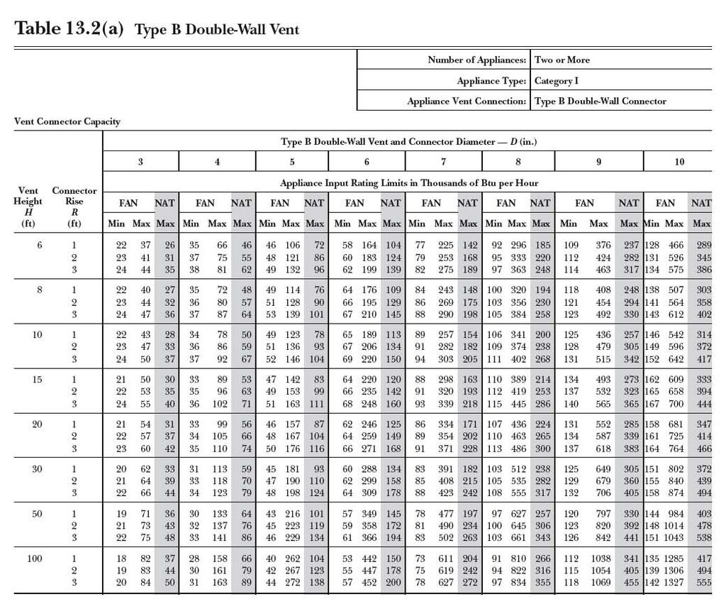
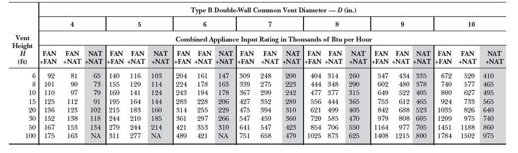
239 268-7
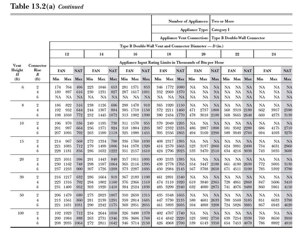
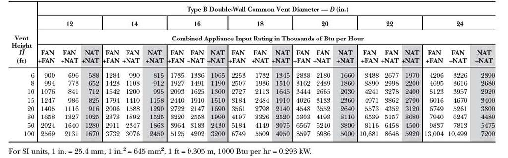
240 268-8

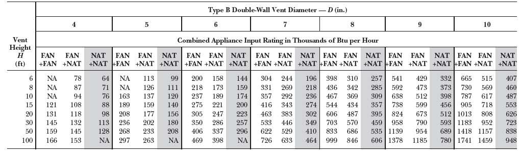
241 268-9
CHAPTER 10 TRAPS AND INTERCEPTORS The vent pipe opening from a soil or waste No more than one (1) approved slip joint
 approved slip joint") CHAPTER 10 TRAPS AND INTERCEPTORS 1001.0 Traps Required. 1001.1 Each plumbing fixture, excepting those having integral traps or as permitted in Section 1001.2, shall be separately trapped by an approved
CHAPTER 10 TRAPS AND INTERCEPTORS 1001.0 Traps Required. 1001.1 Each plumbing fixture, excepting those having integral traps or as permitted in Section 1001.2, shall be separately trapped by an approved
CHaPTeR 10. TRaPS and INTeRCePTORS. Table 10-1 Horizontal lengths of Trap arms (except for water closets and similar fixtures)*
*") CHaPTeR 10 TRaPS and INTeRCePTORS 1001.0 Traps Required. 1001.1 Each plumbing fixture, excepting those having integral traps or as permitted in Section 1001.2, shall be separately trapped by an approved
CHaPTeR 10 TRaPS and INTeRCePTORS 1001.0 Traps Required. 1001.1 Each plumbing fixture, excepting those having integral traps or as permitted in Section 1001.2, shall be separately trapped by an approved
CHAPTER 10 TRAPS AND INTERCEPTORS
 CAPTER 10 TRAPS AND INTERCEPTORS 1001.0 Traps Required. 1001.1 Each plumbing fixture, excepting those having integral traps or as permitted in Section 1001.2, shall be separately trapped by an approved
CHAPTER 10 TRAPS AND INTERCEPTORS TABLE 10-1 HORIZONTAL LENGTHS OF TRAP ARMS (EXCEPT FOR WATER CLOSETS AND SIMILAR FIXTURES) 1, 2
 1, 2") CHAPTER 10 TRAPS AND INTERCEPTORS < 1001.0 Traps Required. Each plumbing fixture, excepting those having integral traps or as permitted in Section 1001.1, shall be separately trapped by an approved type
CHAPTER 10 TRAPS AND INTERCEPTORS < 1001.0 Traps Required. Each plumbing fixture, excepting those having integral traps or as permitted in Section 1001.1, shall be separately trapped by an approved type
CHAPTER 10 TRAPS AND INTERCEPTORS
 CHAPTER 10 TRAPS AND INTERCEPTORS 1001.0 Traps Required. 1001.1 Each plumbing fixture, excepting those having integral traps or as permitted in Section 1001.2, shall be separately trapped by an approved
READ ONLY. Adopting Agency BSC SFM. Adopt Entire Chapter X X X Adopt Entire Chapter as amended (amended sections listed below) X X X X X X X
 X X X X X X X") CALIFORNIA PLUMBING CODE MATRIX ADOPTION TABLE CHAPTER 10 - TRAPS AND INTERCEPTORS (Matrix Adoption Tables are non-regulatory, intended only as an aid to the user. See Chapter 1 for state agency authority
CALIFORNIA PLUMBING CODE MATRIX ADOPTION TABLE CHAPTER 10 - TRAPS AND INTERCEPTORS (Matrix Adoption Tables are non-regulatory, intended only as an aid to the user. See Chapter 1 for state agency authority
Engineering Fact Sheet
 GREASE INTERCEPTORS Service Alert Sensors Cast Iron Access Hatchway General Information Sewers back up an estimated 400,000 times each year in the United States causing approximately 40,000 municipal sanitary
CHAPTER 9 VENTS SECTION
 CHAPTER 9 VENTS SECTION 901 GENERAL 901.1 Scope. The provisions of this chapter shall govern the materials, design, construction and installation of vent systems. 901.2 Trap seal protection. The plumbing
STACKS AND STACK VENTS
 CHAPTER 9 VENTS SECTION 901 GENERAL 901.1 Scope. The provisions of this chapter shall govern the materials, design, construction and installation of vent systems. 901.2 Trap seal protection. The plumbing
Summary of BBS Proposed Ohio Plumbing Code Rule Changes October 2016
 Summary of BBS Proposed Ohio Plumbing Code Rule Changes October 2016 Ohio Administrative Code Rule Number OPC Section IPC origin Reason for proposed 4101:3-2-01 Alternate on-site 2015 Added definition
CHAPTER 9 VENTS. run undiminished in size and as directly as possible from the building drain through to the open air above the roof.
 CHAPTER 9 VENTS SECTION 90 GENERAL run undiminished in size and as directly as possible from the building drain through to the open air above the roof. 90. Scope. The provisions of this chapter shall govern
1 Exam Prep Plumber s Handbook Tabs and Highlights
 1 Exam Prep Plumber s Handbook Tabs and Highlights These 1 Exam Prep Tabs are based on the Plumber s Handbook Revised 2006. Each Tabs sheet has five rows of tabs. Start with the first tab at the first
SCHOOL DISTRICT PALM BEACH COUNTY BUILDING DEPARTMENT PLAN REVIEW CHECK LIST -- PLUMBING
 SCHOOL DISTRICT PALM BEACH COUNTY BUILDING DEPARTMENT PLAN REVIEW CHECK LIST -- PLUMBING 3300 SUMMIT BOULEVARD WEST PALM BEACH, FLORIDA 33406 TEL (561) 688-7687 FAX (561) 688-7654 http://www.palmbeach.k12.fl.us/fm/bd/index.htm
Sanitary Drainage Systems
 11.1 MATERIALS See Section 3.1. Sanitary Drainage Systems 11.2 BUILDING SEWERS AND BUILDING DRAINS 11.2.1 Sewer or Drain in Filled Ground Chapter 11 Building sewers or building drains that are installed
Read Only Document Not For Distribution
 Chapter 5 Traps, Cleanouts and Backwater Valves 5.1 SEPARATE TRAPS FOR EACH FIXTURE a. Plumbing fixtures shall be separately trapped by a water seal trap placed as close as possible to the fixture outlet.
ICP Plumbing Exam. Name: Carefully read each question and then circle the letter of the best answer.
 ICP Plumbing Exam Name: Date: Score: Carefully read each question and then circle the letter of the best answer. 1. A 1 inch diameter faucet, where the inside edge of the spout opening is 2.5 inches away
Read Only Document Not For Distribution
 Chapter 9 Indirect Waste Piping and Special Wastes 9.1 INDIRECT WASTES 9.1.1 General Drains from fixtures, fixture compartments, equipment, appliances, appurtenances, and other devices requiring protection
MATERIALS Traps TRAPS. No. IPC IRC Description
 MATERIALS Traps TRAPS MAX " MAX 0" No. IPC IRC Description 00. P0.6 00. P0.6 00. P0. 00. () P0.6 Exc. Vertical distance from fixture to the trap weir can not exceed ". Horizontal distance from the fixture
GREASE REMOVAL DEVICE GUIDELINES FOR PLOT/PLUMBING PLAN DRAWINGS AND INSTALLATION REQUIREMENTS
 GREASE REMOVAL DEVCE GUDELNES FOR PLOT/PLUMBNG PLAN DRAWNGS AND NSTALLATON REQUREMENTS The removal of fats, oils, and grease (FOG) from kitchen wastewater is an essential operational requirement for Food
APPENDIX J ILLUSTRATIONS
 The following figures have been included in the 1994 edition of the Standard Plumbing Code to aid in interpreting this code. The figures are not to be construed as superseding the written text, but merely
Public Input No. 1-NFPA [ Global Input ] Additional Proposed Changes. Statement of Problem and Substantiation for Public Input
![Public Input No. 1-NFPA [ Global Input ] Additional Proposed Changes. Statement of Problem and Substantiation for Public Input](/thumbs/85/92902642.jpg "Public Input No. 1-NFPA [ Global Input ] Additional Proposed Changes. Statement of Problem and Substantiation for Public Input") of 280 2/6/2015 12:06 PM Public Input No. 1-NFPA 58-2013 [ Global Input ] NOTE: This public input originates from Tentative Interim Amendment 58-14-1 (TIA 1079) issued by the Standards Council on August
of 280 2/6/2015 12:06 PM Public Input No. 1-NFPA 58-2013 [ Global Input ] NOTE: This public input originates from Tentative Interim Amendment 58-14-1 (TIA 1079) issued by the Standards Council on August
Subject: BSR Uniform Mechanical Code, 2015 Edition: Appeal on Proposal #333
 Paul Cabot Administrator National Fuel Gas Ms. Gabriella Davis Recording Secretary, IAPMO Standards Council International Association of Plumbing and Mechanical Officials (IAPMO) IAPMO Group World Headquarters
Grease Interceptors and Oil Separators
 Grease Interceptors and Oil Separators 1) All food service establishments and vehicle maintenance facilities shall have devices installed for separating and retaining grease and oils known as grease interceptors
CHAPTER 31. VENTS Reserved 2003 INTERNATIONAL RESIDENTIAL CODE 425R
 CHAPTER 31 VENTS Reserved 2003 INTERNATIONAL RESIDENTIAL CODE 425R This page left intentionally blank. 426R 2003 INTERNATIONAL RESIDENTIAL CODE For SI: PIPE SIZE (inches) TABLE P3107.3 COMMON VENT SIZES
ARTICLE 25. FUEL GAS CODE
 ARTICLE 25. Rule 1. Indiana Fuel Gas Code, 2003 Edition (Repealed) (Repealed by Fire Prevention and Building Safety Commission; filed Mar 18, 2008, 2:32 p.m.: 20080423-IR-675070479FRA, eff 90 days after
APPENDIX A. A 3.2 Determine the elevation of the highest. A 3.3 Subtract the sum of loss in static pressure
 APPENDIX A RECOMMENDED RULES FOR SIZING THE WATER SUPPLY SYSTEM Because of the variable conditions encountered, it is impractical to lay down definite detailed rules of procedure for determining the sizes
APPENDIX F: GREASE SEPARATION DEVICE SIZING OPTIONS
 APPENDIX F: GREASE SEPARATION DEVICE SIZING OPTIONS 55 Method 1. Evaluation Based upon 20-25 Minute Hydraulic Retention Grease Separation Device Sizing Table Maximum, worst-case hydraulic loading conditions
GREASE SEPARATION DEVICE SIZING OPTIONS
 GREASE SEPARATION DEVICE SIZING OPTIONS Method 1. Evaluation Based upon 20-25 Minute Hydraulic Retention Grease Separation Device Sizing Table Maximum, worst-case hydraulic loading conditions typified
APPENDIX L ALTERNATE PLUMBING SYSTEMS
 ALTERNATE PLUMBING SYSTEMS L 1.0 General. L 1.1 Applicability. The intent of this appendix is to provide clarification of procedures for the design and approval of engineered plumbing systems, alternate
2016 Plumbing Supplemental Plan Review List
 Building Division 555 Santa Clara Street Vallejo CA 94590 707.648.4374 2016 Plumbing Supplemental Plan Review List POTABLE WATER SYSTEM P1. Specify which fixtures are for private use and which are for
Grease Interceptors. General For the purpose of this standard, the following terms shall have the meaning indicated in this section.
 Building Division 4800 W. 92 nd Avenue Westminster, Colorado 80031 303-658-2075 permits@cityofwestminster.us Grease Interceptors Where Required Every food serving, food preparing, food catering, or meat
Design of Precast Concrete Grease Interceptors
 Design of Precast Concrete Grease Interceptors Claude Goguen, PE National Precast Concrete Association 2015 Onsite Wastewater Mega Conference Terminology Terminology Terminology Grease is the Word If you
4. TECHNOLOGY AND DESIGN CRITERIA
 4. TECHNOLOGY AND DESIGN CRITERIA 12 Current FOG pretreatment technology typically takes the form of smaller, metal, grease-handling devices found in the kitchen area of the facility; or large, in-ground,
2018 National Fuel Gas Code Summary List of Revisions Updated: 7/27/17
 The following list contains a summary of the significant revisions in the 2015 National Fuel Gas Code approved by the National Fuel Gas Code Committee, ANSI ASC Z223 and NFPA 54. 1.1.1.1 (B), (C), & (D)
Level I Chapter 1 Worksheet
 Chapter 1 Worksheet 1. For applicability requirements of the Plumbing Code, refer to: a. Building Code b. Administration and Enforcement Code c. Plumbing Code d. Residential Code 2. The provisions of the
FACT SHEET 2018 National Fuel Gas Code Summary List of Revisions rev
 This fact sheet provides an overview of the significant revisions in the 2015 National Fuel Gas Code approved by the National Fuel Gas Code Committee, ANSI ASC Z223 and NFPA 54. These revisions are published
CHAPTER VI BUILDING PLUMBING
 CHAPTER VI BUILDING PLUMBING 6.1. INTRODUCTION The chapter covers questions related to water demand, distribution and drainage. The basic principles for planning and installing common plumbing systems
CALIFORNIA PLUMBING CODE MATRIX ADOPTION TABLE APPENDIX A - RECOMMENDED RULES FOR SIZING THE WATER SUPPLY SYSTEM 1 2 1/AC AC SS SS/CC
 CALIFORNIA PLUMBING CODE MATRIX ADOPTION TABLE APPENDIX A - RECOMMENDED RULES FOR SIZING THE WATER SUPPLY SYSTEM Adopting Agency BSC SFM HCD DSA OSHPD CSA DPH AGR DWR CA 1 2 1/AC AC SS SS/CC 1 2 3 4 Adopt
Matrix of changes for the National Standard Plumbing Code July 2013
 Matrix of changes for the National Standard Plumbing Code July 2013 Item # Section Number Person Submitting Change Committee Action 10-77 10.20.8 and Table 3.1.3 XI Certification 10-82 12.16 Size and Lengths
2015 UPC CODE - CHAPTER 8 INDIRECT WASTES
 801.0 General. 2015 UPC CODE - CHAPTER 8 INDIRECT WASTES 801.1 Applicability. This chapter shall govern the materials, design, and installation of indirect waste piping, receptors, and connections; and
IPC Plumbing Exam. Name: Carefully read each question and then circle the letter of the best answer.
 IPC Plumbing Exam Name: Date: Score: Carefully read each question and then circle the letter of the best answer. 1. A vent stack handling 25 dfu s with a developed length of 35 feet shall be inches minimum
ENERGY MARKETING SERVICES
 1 IMPORTANT STUFF This manual has been designed as a supplemental aid for students preparing to take the Plumbing Exam based on the international codes. It is not intended to replace any manuals or material
Is Sewer Gas Giving Your Customers the Wrong Impression?
 Is Sewer Gas Giving Your Customers the Wrong Impression? Prepared by Dialectic INTRODUCTION We ve all been there. You walk into a public restroom and you immediately wonder if one of the toilets is overflowing.
PLUMBING REQUIREMENTS
 PLUMBING REQUIREMENTS This handout is a compilation of the standard requirements based on the State Plumbing Code and City Ordinance for projects of this type. This information sheet does not contain all
Methods of Venting Plumbing Fixtures and Traps in the 2018 IPC
 People Helping People Build a Safer World Methods of Venting Plumbing Fixtures and Traps in the 2018 IPC Installation, Flexibility and Opportunity for Savings Lee Clifton, Senior Director of PMG Resources,
2015 National Fuel Gas Code Summary List of Revisions Updated: 04/24/14
 The following list contains a summary of the significant revisions in the 2015 National Fuel Gas Code approved by the National Fuel Gas Code Committee, ANSI ASC Z223 and NFPA 54. PIPING Various Brass REVISED
PROPOSED CODE CHANGES FOR REVIEW BY THE FIRE CODE ACTION COMMITTEE
 PROPOSED CODE CHANGES FOR REVIEW BY THE FIRE CODE ACTION COMMITTEE Developed by the Midwestern Regional Work Group CONTENTS Item 15 Limited area sprinkler systems Item 20 Scope of IFC Ch 7 Item 21 Fire-resistance-rated
INSPECTION OF COMMERCIAL KITCHEN PLUMBING
 INSPECTION OF COMMERCIAL KITCHEN PLUMBING 801.1 SCOPE Food-handling establishments 2 - by John Williams, Jr. Plumbing Control Supervisor Onondaga County Water Environment Protection Commercial Kitchens
Dear Concessionaire,
 Dear Concessionaire, In order to provide a comprehensive review & inspection of the Vendor application please review the following as guidance to a complete application and preparedness for inspection.
A GUIDE TO PASSING THE PLUMBING EXAM
 A GUIDE TO PASSING THE PLUMBING EXAM BASED ON THE INTERNATIONAL PLUMBING AND FUEL GAS CODES WRITTEN BY JOHN WHITE REVISED 2014 2007-2014 This manual is the sole property of Energy Marketing Services. No
Fire District Dwelling Construction Requirements
 Fire District Dwelling Construction Requirements Includes Sacramento County Fire Marshals Association Standard for Residential Sprinklers City of Rancho Cordova Building & Safety Department 2729 Prospect
c. Direct or indirect?
 ~ \ 1.) GENERAL a. Definitions: Chapter B Code References (1) Air-break Comm 81.01 (5) (2) Air-gap, drain system Comm 81.01 (6) (3) Flood level rim Comm 81.01(102) (4) sink Comm 81.01(105) (5) Indirect
4. Committee Member presentation of New Items for consideration by the committee (Written ideas with discussion, maximum 5 minutes each.
 AGENDA for PMG CODE ACTION COMMITTEE TELECONFERENCE CALL MEETING ON TUESDAY 13 MAY 2014 Starting at 11am CDT (12pm EDT, 10am MDT, 9am PDT) Scheduled Length of Meeting: 2 hours The Dial-in Number is 1-800-910-8278
Section 2, Reference publications: Updated the referenced publications to the current editions.
 Summary of Substantive Changes between the 2014 and the 2015 editions of ANSI Z21.10.3 CSA 4.3 Gas fired water heaters, volume III, storage water heaters with input ratings above 75,000 Btu per hour, circulating
National Fire Protection Association. 1 Batterymarch Park, Quincy, MA Phone: Fax:
 National Fire Protection Association 1 Batterymarch Park, Quincy, MA 02169-7471 Phone: 617-770-3000 Fax: 617-770-0700 www.nfpa.org M E M O R A N D U M TO: FROM: NFPA Technical Committee on Mercantile and
National Fire Protection Association. 1 Batterymarch Park, Quincy, MA Phone: Fax:
 National Fire Protection Association 1 Batterymarch Park, Quincy, MA 02169-7471 Phone: 617-770-3000 Fax: 617-770-0700 www.nfpa.org M E M O R A N D U M TO: FROM: Technical Committee on Standpipes Elena
INFORMATION FOR TANKLESS WATER HEATERS
 GAS PIPING INFORMATION FOR TANKLESS WATER HEATERS Details Details regarding regarding properly properly sized sized gas lines lines for for use use with with tankless tankless water water heaters heaters
Public Input No. 52-NFPA [ Section No [Excluding any Sub-Sections] ]
![Public Input No. 52-NFPA [ Section No [Excluding any Sub-Sections] ]](/thumbs/81/83983503.jpg "Public Input No. 52-NFPA [ Section No [Excluding any Sub-Sections] ]") 8 of 93 11/6/2015 7:41 AM Public Input No. 52-NFPA 30-2015 [ Section No. 21.2 [Excluding any Sub-Sections] ] For the purpose of this chapter, the term in this section shall have the definitions given.
8 of 93 11/6/2015 7:41 AM Public Input No. 52-NFPA 30-2015 [ Section No. 21.2 [Excluding any Sub-Sections] ] For the purpose of this chapter, the term in this section shall have the definitions given.
Plumbing. Definitions. Background Factors. Air Chambers. Air Gap (Drainage System) Air Gap (Water Distribution System) Air Lock.
 Air Gap (Water Distribution System) Air Lock.") Plumbing Plumbing may be defined as practice, materials, and fixtures used in the installation, maintenance, and alteration of all piping, fixtures, appliances, and appurtenances in connection with sanitary
Plumbing Plumbing may be defined as practice, materials, and fixtures used in the installation, maintenance, and alteration of all piping, fixtures, appliances, and appurtenances in connection with sanitary
Gas Piping Facts. Information for properly sizing gas lines for use with tankless water heaters and other gas appliances TANKLESS WATER HEATING
 TANKLESS WATER HEATING Gas Piping Facts Information for properly sizing gas lines for use with tankless water heaters and other gas appliances With any gas appliance, it is essential that the gas supply
National Fire Protection Association M E M O R A N D U M. Technical Committee on Testing and Maintenance of Fire Alarm and Signaling Systems
 National Fire Protection Association 1 Batterymarch Park, Quincy, MA 02169-7471 Phone: 617-770-3000 Fax: 617-770-0700 www.nfpa.org M E M O R A N D U M TO: FROM: Technical Committee on Testing and Maintenance
1 Exam Prep Plumbing State Contractors Practice Exam 2
 1 Exam Prep Plumbing State Contractors Practice Exam 2 1 According to Chapter 64E-6, when sizing a grease interceptor used in a restaurant, the correct formula is. A. (S) x (EW 12) x (LF) B. (S) x (GS)
Pipe Sizing Table. Hydraulic Load Served (fixture units)
") MODULE 1 INTRODUCTION Notes: A Pipe Type Horizontal branch Pipe Sizing Table Hydraulic Load Served (fixture units) Size (in.) Code Reference 2 + 1.5 = 3.5 2 7.4.9.1.(1) B Soil stack 13.5 + 13.5 = 27 3
MODULE 1 INTRODUCTION Notes: A Pipe Type Horizontal branch Pipe Sizing Table Hydraulic Load Served (fixture units) Size (in.) Code Reference 2 + 1.5 = 3.5 2 7.4.9.1.(1) B Soil stack 13.5 + 13.5 = 27 3
IPC Plumbing Exam. Name: Carefully read each question and then circle the letter of the best answer.
 IPC Plumbing Exam Name: Date: Score: Carefully read each question and then circle the letter of the best answer. 1. The minimum air gap for a fixture with an effective open of 1/2", located away from a
Combined Hand-Washing Systems
 IAPMO IGC 127-20142018 PUBLIC REVIEW DRAFT Combined Hand-Washing Systems IAPMO Standard IAPMO IGC 127 20142018 Published: January 2014 Previous Editions: January 2014, July 2013, April 2013, April 2009,
M E M O R A N D U M. NFPA Technical Committee on Building Services and Fire Protection Equipment
 M E M O R A N D U M TO: FROM: NFPA Technical Committee on Building Services and Fire Protection Equipment Linda MacKay DATE: November 10, 2009 SUBJECT: NFPA 5000 A2011 ROP Letter Ballot Final Results The
FOOD ESTABLISHMENT CONSTRUCTION GUIDE Revised December 19, 2011 Reviewed January 10, 2014
 FOOD ESTABLISHMENT CONSTRUCTION GUIDE Revised December 19, 2011 Reviewed January 10, 2014 This construction guide is to be used in conjunction with the Oklahoma Food Service Establishment Regulations (OAC
Food Service Plan Review Information
 Food Service Plan Review Information New or remodeled food preparation facilities, and those changing ownership, must undergo a plan review process prior to a health permit being issued. The purpose of
Food Establishment Guidelines. Food Service Plan Review
 Food Service Plan Review Food service plan review in the City of Grand Prairie begins at the Environmental Services Department at the Development Center, 201 NW 2 nd Street in Suite 100. The City of Grand
DESIGN AND CONSTRUCTION STANDARDS GENERAL DESIGN GUIDELINES
 2.05 PLUMBING GENERAL DESIGN AND CONSTRUCTION STANDARDS GENERAL DESIGN GUIDELINES - 2.05 It is expected that the plumbing design professional will conform to accepted good engineering design practices.
Changes for the New Edition. Senior Engineer, NFPA NFPA
 Changes for the New Edition Denise Beach Senior Engineer, NFPA NFPA Overview NFPA 58-2014 Substantive Changes TIAs 2017 Edition NFPA 58-2014 Substantive Changes Bulk and Industrial Plants 3.3.10 Bulk Plant.
Analysis of Changes for the 5 th Edition (2014) of the Florida Codes
 of the Florida Codes") Analysis of Changes for the 5 th Edition (2014) of the Florida Codes Changes to the Florida Building Code, Fuel-Gas This Analysis of Changes for the 5 th Edition (2014) of the Florida Codes is intended
Analysis of Changes for the 5 th Edition (2014) of the Florida Codes Changes to the Florida Building Code, Fuel-Gas This Analysis of Changes for the 5 th Edition (2014) of the Florida Codes is intended
Second Revision No. 20-NFPA [ Section No. 1.4 ] Supplemental Information. Submitter Information Verification. Committee Statement
![Second Revision No. 20-NFPA [ Section No. 1.4 ] Supplemental Information. Submitter Information Verification. Committee Statement](/thumbs/79/80346596.jpg "Second Revision No. 20-NFPA [ Section No. 1.4 ] Supplemental Information. Submitter Information Verification. Committee Statement") Second Revision No. 20-NFPA 14-2015 [ Section No. 1.4 ] 1.4* Equivalency. Nothing in this standard is intended to prevent the use of systems, methods, or devices of equivalent or superior quality, strength,
Second Revision No. 20-NFPA 14-2015 [ Section No. 1.4 ] 1.4* Equivalency. Nothing in this standard is intended to prevent the use of systems, methods, or devices of equivalent or superior quality, strength,
National Fire Protection Association M E M O R A N D U M. NFPA Technical Committee on Residential Sprinkler Systems
 National Fire Protection Association 1 Batterymarch Park, Quincy, MA 02169-7471 Phone: 617-770-3000 Fax: 617-770-0700 www.nfpa.org M E M O R A N D U M TO: FROM: NFPA Technical Committee on Residential
Report on First Revision June 2014 NFPA 5000
 5000- Log #12 BLD-BSF Final Action: (55.2 (New) ) NOTE: This proposal appeared as Comment 5000-168 (Log #86) which was held from the A11 ROC on Proposal 5000-239. Submitter: Technical Correlating Committee
Product Overview. About Us. Grease Traps Generic Types. Extended Capacity Hydromechanical Grease Traps
 About Us Product Overview Extended Capacity Hydromechanical Grease Traps Endura XL 75 Models DGT75 598L Light Trafficable Lid DGT75P 598L Pedestrian Lid Industry leading separation efficiency based on
TABLE OF CONTENTS. CHAPTER 2 DEFINITIONS General Applicability Definition of Terms General...
 TABLE OF CONTENTS CHAPTER 1 ADMINISTRATION................1 101.0 Title, Scope, and General...........1 101.1 Title............................1 101.2 Purpose.........................1 101.3 Plans Required...................1
Fats, Oils and Grease Program (FOG)
") Fats, Oils and Grease Program (FOG) SECTION A GENERAL INFORMATION 1. Facility Name: 2. Facility Street Address: City: State: Zip: Phone Number: Fax Number: 3. Business Mailing Address: (if different from
Fats, Oils and Grease Program (FOG) SECTION A GENERAL INFORMATION 1. Facility Name: 2. Facility Street Address: City: State: Zip: Phone Number: Fax Number: 3. Business Mailing Address: (if different from
Uniform Mechanical Code
 Uniform Mechanical Code 2019 Technical Committee Meeting Monograph Denver, Colorado Sheraton Denver Downtown Hotel May 1 2, 2019 TABLE OF CONTENTS I II III Tentative Agenda Tentative Order of Discussion
CHAPTER 5 Water, Plumbing, and Waste
 CHAPTER 5 Water, Plumbing, and Waste Parts 5-1 Water 5-2 Plumbing System 5-3 Mobile Water Tank 5-4 Sewage, Other Liquid Waste, and Rainwater 5-5 Refuse, Recyclables, and Returnables 5-1 Water 5-101 Source
GARCIA GALUSKA DESOUSA Consulting Engineers
 L#58619/Page 1/November 1, 2017 PLUMBING Executive Summary: Presently, the Plumbing Systems serving the building are cold water, hot water, sanitary, waste and vent system, storm drain piping, and natural
168 Spotnap Road Charlottesville, VA Tel (434) Fax (434)
 Fax (434)") Re: Fats, Oils and Grease (FOG) Abatement Program Dear Restaurant/Food Service Facility Manager: The Albemarle County Service Authority (ACSA) prides itself on maintaining the general public health of
Re: Fats, Oils and Grease (FOG) Abatement Program Dear Restaurant/Food Service Facility Manager: The Albemarle County Service Authority (ACSA) prides itself on maintaining the general public health of
CHAPTER 5: EXHAUST SYSTEMS
 MOTORS, FANS AND FILTERS 503.1 General. Motors and fans shall be sized to provide the required air movement. Motors in areas that contain flammable vapors or dusts shall be of a type approved for such
National Fire Protection Association. 1 Batterymarch Park, Quincy, MA Phone: Fax:
 National Fire Protection Association 1 Batterymarch Park, Quincy, MA 02169-7471 Phone: 617-770-3000 Fax: 617-770-0700 www.nfpa.org MEMORANDUM TO: FROM: Technical Committee on Residential Occupancies Kelly
SECTION PLUMBING
 SECTION 22 10 00 PLUMBING PART 1 GENERAL 1.1 WORK INCLUDED A. Furnish all labor, material and equipment necessary for the complete installation of the sanitary sewer system (including soil and vent piping),
Why Selective Coordination is Mandatory -- It Fills the Reliability Hole --
 Why Selective Coordination is Mandatory -- It Fills the Reliability Hole -- The NEC has mandatory selective coordination requirements for the following systems. Emergency Systems- Article 700 700.27 Legally
SIZING HANDBOOK & APPLICATION GUIDE
 SIZING HANDBOOK SIZING HANDBOOK & APPLICATION GUIDE Chimney & Gas Vent For Capacities to 100 Million B.T.U. The primary aim of this Sizing Handbook is to provide more detailed guidance on appliance venting
Denotes a new question! Denotes a revised/revisited question. September 2009 General:
 General: 1) (Q) What does a contractor/permit holder have to supply for an inspection? (A) Section 107.2 of the NC Administrative Code states that it is the duty of the permit holder to provide access
How To Size A Big Dipper Unit
 Sizing Big Dipper Systems In Food Service Operations How To Size A Big Dipper Unit The purpose of this sizing procedure is to give a specifying engineer a simple method for determining the proper size
DOMESTIC WATER PACKAGED BOOSTER PUMPS
 DIVISION 22 PLUMBING 22 11 16 DOMESTIC WATER PIPING 22 11 19 DOMESTIC WATER PIPING SPECIALTIES 1. To facilitate landscape and other maintenance operations, exterior hose bibs shall be provided at 150 foot
TABLE OF CONTENTS Limitations of Authority...6 Table Swimming Pool, Spa, and Hot Tub Permit Fees...7
 TABLE OF CONTENTS CHAPTER 1 ADMINISTRATION..............1 101.0 General.......................1 101.1 Title..........................1 101.2 Scope........................1 101.3 Purpose......................1
Committee on NFPA 51A
 Committee on M E M O R A N D U M TO: FROM: NFPA Technical Committee on Industrial and Medical Gases Patti Mucci, Administrative Assistant DATE: May 6, 2010 SUBJECT: ROC Letter Ballot The ROC letter ballot
AIRPORT PLUMBING DESIGN STANDARDS REV. 2 11/02/2015
 1.1 GOALS The goal of this section is to provide guidance in the design of Plumbing and Fire Protection systems to LAWA standards. The LAWA Plumbing Design Standards are a compilation of general design
HOW THE RIGHT GREASE INTERCEPTOR CAN HELP YOU SAVE SPACE IN A COMMERCIAL KITCHEN
 HOW THE RIGHT GREASE INTERCEPTOR CAN HELP YOU SAVE SPACE IN A COMMERCIAL KITCHEN INTRODUCTION: THE UNCONVENTIONAL KITCHEN Many engineers and architects are all too familiar with this scenario: You ve been
IPC CODE AND COMMENTARY
 2012 IPC CODE AND COMMENTARY 2012 International Plumbing Code Commentary First Printing: March 2012 ISBN: 978-1-60983-070-0 (soft-cover) COPYRIGHT 2012 by INTERNATIONAL CODE COUNCIL, INC. ALL RIGHTS RESERVED.
SOMERSWORTH CODE FIRE PREVENTION AND LIFE SAFETY CHAPTER 21
 SOMERSWORTH CODE FIRE PREVENTION AND LIFE SAFETY CHAPTER 21 ARTICLE I FIRE PREVENTION CODE 21-1. Statutory authority 21-2. Adoption of standards 21-3. Definitions 21-4. Exceptions to Fire Prevention Code
2015 MPC, MMC and IFGC Significant Changes
 2015 MPC, MMC and IFGC Significant Changes Based on the 2015 Michigan Plumbing Code, (MPC), the 2015 Michigan Mechanical Code (MMC) and the 2015 International Fuel GaS Code (IFGC) Purpose This program
2015 UPC Chapter 8 Indirect Wastes RV
 PLEASE DO NOT BOOKMARK ANY ANYTIMECE WEBPAGES! Our system will remember the last page you viewed when logging out and back in but please DO NOT exit out when taking a test. Your place will NOT be saved.
National Fire Protection Association. 1 Batterymarch Park, Quincy, MA Phone: Fax:
 National Fire Protection Association 1 Batterymarch Park, Quincy, MA 02169-7471 Phone: 617-770-3000 Fax: 617-770-0700 www.nfpa.org M E M O R A N D U M TO: FROM: NFPA Technical Committee on Hot Work Operations
Second Revision No. 104-NFPA [ Section No ] Submitter Information Verification. Committee Statement
![Second Revision No. 104-NFPA [ Section No ] Submitter Information Verification. Committee Statement](/thumbs/87/97199093.jpg "Second Revision No. 104-NFPA [ Section No ] Submitter Information Verification. Committee Statement") of 1 9/22/2014 1:38 PM Second Revision No. 104-NFPA 72-2014 [ Section No. 3.3.3 ] 3.3.3 Accessible, Readily (Readily Accessible). Capable of being reached quickly for operation, renewal, or inspections
of 1 9/22/2014 1:38 PM Second Revision No. 104-NFPA 72-2014 [ Section No. 3.3.3 ] 3.3.3 Accessible, Readily (Readily Accessible). Capable of being reached quickly for operation, renewal, or inspections