TECHNICAL REPORT 3 Mechanical Systems and Existing Conditions Northfield Mental Healthcare Center Northfield, Ohio
|
|
|
- Philip Watkins
- 5 years ago
- Views:
Transcription


1 Technical Report 3 Northfield Mental Healthcare Center Dr. Stephen Treado Ji Won Park Mechanical Option Fall 2012 TECHNICAL REPORT 3 Mechanical Systems and Existing Conditions Northfield Mental Healthcare Center Northfield, Ohio Ji Won Park Mechanical Option Faculty Consultant: Dr. Stephen Treado Date revised and submitted: November, 12 nd, 2012
2 TABLE OF CONTENTS EXECUTIVE SUMMARY... 3 SECTION ONE. PROJECT BACKGROUND Project Background Existing Mechanical System Summary Design Criteria Design Condition VENTILATION REQUIREMENTS MECHANICAL EQUIPMENT SUMMARY MECHANICAL FIRST COSTS LOST USABLE SPACE System Operation AIR SIDE OPERATION WATER SIDE OPERATIONS Model Design Lighting and Equipment Electrical Load Assumptions Occupancy Assumptions Airflow Assumptions Construction of Building Envelope Designed Temperature Control Energy Modeling - Output Cooling, Heating, and Ventilation Load Domestic Hot and Cold Water Load Energy Consumption Emission
3 1.8 LEED Analysis Energy and Atmosphere Indoor Environmental Quality Overall Evaluation Summary REFERENCE APPENDIX A: The Minimum Outdoor Airflow Requirement in Accordance of the ASHRAE Standard 62.1 and the ASHRAE Standard APPENDIX B: Mechanical First Costs
4 EXECUTIVE SUMMARY The Northfield Mental Healthcare center is located on the Northfield, Ohio. The building is a five story mental clinic building, and the project is renovation of three existing buildings and expansion of the existing facilities. Approximately 200,000 square feet would be added to the existing buildings, and the new portions of the buildings would be served as patient wings, administration, gymnasium, and clinic center. The new buildings were designed to provide better quality of building, safety of patients and staff, and aesthetically pleasing environment. The face brick walls were mainly used for the exterior walls, and smooth CMU, texted CMU, and curtain walls were also used to highlight freshness of new design. The building is not yet constructed but still in constructional document phase. The total estimated project cost is approximately $62.5 million, including 10.3 million of HVAC and fire protection equipment cost. This report contains the analysis of existing mechanical systems on the Northfield Mental Healthcare Center. The purpose of this report is to evaluate the existing mechanical systems by defining design objectives, the outdoor and indoor design conditions, annual energy usage, and overall evaluation of mechanical system. Mechanical equipment summary contains constructions of air handling units, boiler schedule, and chiller schedule. System operation section describes how chilled water and hot water are generated and served to the entire building. Each description contains a schematic drawing of each system. This report also contains LEED analysis, but since this facility does not aim to be LEED certified, LEED analyses on certain sections are performed. Even if the building is not LEED 3
5 certified building, this building utilizes some of the sustainable features such as highly insulated exterior envelope, efficient equipment, programmable temperature controls, occupancy sensors, and so on. SECTION ONE. PROJECT BACKGROUND 1.1 PROJECT BACKGROUND The Northfield Mental Healthcare center is located in Northfield, Ohio. The building is a five-story mental clinic building, and the project is a renovation and expansion of three existing buildings. Approximately 200,000 square feet would be added to the existing buildings, and the new portions of the buildings would be for patient wings, an administrative facility, a gym, and a clinic. The new buildings were designed to provide better quality for the structures, deliver to the safety of patients and staff, and to become an aesthetically pleasing environment. The main goal of the Northfield Mental Healthcare center project is to provide a comfortable and safe environment for both patients and staff members. The main purpose of this project is to establish more spaces for additional patients transferred from the Cleveland healthcare campus, which is going to be closed after the completion of this project. The building is not yet constructed, as it is still in the bidding process. The total estimated project cost is approximately $62.5 million, including $10.3 million for HVAC and fire protection equipment costs. 4
6 1.2 EXISTING MECHANICAL SYSTEM SUMMARY From this section, the existing mechanical system is referred to a newly designed mechanical system for The Northfield Mental Healthcare center expansion and renovation project. 10 different air-handling units are equipped in the Northfield Mental Healthcare Center, including two already existing air handlers. Two 65,000 CFM rooftop air handlers serve the two patient wings. Clinic and administration areas are served by a 7,950 CFM rooftop air handler. A 3,700 CFM indoor air handler and an 8,400 CFM indoor air handler serve the gym area and dietary areas, respectively. The boiler plant, chiller plant, and electrical room are served by the other three indoor air handlers, which have a maximum capacity of 5,000 CFM, 5,000 CFM, and 6,000 CFM, respectively. The existing air handlers serve partially renovated areas and existing administration areas. Customized air handler 1 and 2 for the two patient wings are equipped with DDC-VAV terminals, which will reset the ventilation rate based on occupancy. The DDC-VAV terminals continuously measure the amount of supply air and ventilation fraction for each space. A building automation system controls the DDC-VAV terminals and outdoor airflow by changing the position of the outdoor air dampers. The control system of a DDC-VAV terminal is described in the Figure 1. 5

7 Figure 1: Ventilation Control by DDC-VAV Terminals Air handler 3, which serves the gym area, is a dedicated outdoor air unit equipped with a sensible wheel. A total energy enthalpy wheel preconditions the outdoor air transferred to the unit. The total enthalpy wheel cools the outdoor air to F DB during the cooling season and heats the outdoor air to F DB during heating season, before delivering the conditioned outdoor air to the cooling coil and heating coil. The building use programmable temperature control sensors and occupancy sensors, which reduce equipment load by a significant amount. Since most of the openings in the building are not operative, the amount of the outside air for each air handler is oversized in order to achieve the better indoor air quality. In order to maintain the comfortable temperature, even with the great amount of outside air entering the building, cabinet unit heaters and horizontal unit heaters are additionally placed to efficiently meet the space heating load. 6
8 Two 450-ton centrifugal chillers are located in the chiller plant and connected to a 2-cellcooling tower, which is located outside of the energy center. Each chiller consists of two chilled water pumps: a primary chilled water pump and a secondary chilled water pump. The primary and secondary pumping arrangements help to increase system controllability, while decreasing total power input. It is recommended to use primary and secondary pumping systems for large complexes, all for energy efficiency. The primary chilled water pumps serve chilled water to chillers, while secondary chilled water pumps send chilled water to a cooling coil for each air handling equipment to serve the cooling load of the building. Six horsepower condensing boilers are located in the boiler plant and serve hot water. A primary pump equipped with each boiler sends heated water to the main hot water loop. Two secondary pumps, along with the main hot water loop, send hot water to a heating coil for each air handling equipment to serve the heating load of the building. Makeup water is heated by two domestic water heaters and served to the building. Variable frequency drive devices are used for most of the HVAC equipment, including heating water pumps, chilled water pumps, chillers, and cooling towers. Figure 2 shows the existing heating and cooling system. 7


9 Figure 2: Existing Heating and Cooling System 1.3 DESIGN CRITERIA The main goal of the Northfield Mental Healthcare center is to provide comfortable and safe environment for both patients and staff members. The main purpose of this project is establishing more spaces for additional patients transferred from Cleveland healthcare campus which is going to be closed after completion of this project. Since some of the mechanical 8
10 systems remain the same, the newly designed mechanical systems need to be balanced with the existing one. Ten air handlers will serve the entire building, but two of them are existing one serving partially renovated areas and existing administration areas. Since the total pressure drop over the ductwork finally connected to the existing air handler remain the same, the total pressure drop accumulated through the newly designed ductwork needs to be balanced with that of ductwork which will be demolished. The total designed energy load consists of cooling, heating loads and dominatingly hospital equipment load. This equipment load can significantly be reduced by using programmable temperature control sensor and occupancy sensors. Since the most of openings in the building are not operative, infiltrations as well as ventilation are one of the major design concerns. The amount of the outside air takes an account of infiltrations, and the amount of the outside air would be defined in accordance of ASHRAE 62.1 and ASHRAE 170. The amount of the outside air was oversized in order to achieve the better indoor air quality. In order to maintain the comfortable temperature even with the great amount of the outside air entering into the building, cabinet unit heaters and horizontal unit heaters were designed to be placed for the winter. The heating water systems and cooling water systems have primary and secondary distribution systems that are recommended by ASHRAE Standard It is recommended to use primary and secondary pumping system for large complexes for energy efficiency. The primary and secondary pumping arrangements help to increase system controllability and decrease total horsepower required. The primary pump serves chillers and boilers, while the secondary pump serves the cooling load and heating load. 9
11 1.3.1 DESIGN CONDITION The Northfield Mental Healthcare Center is located in Northfield, OH. Since the Northfield area is not listed in the ASHRAE Fundamental 2009, Cleveland, the closest big city, was used for the analysis. Table 1 shows the weather data inputs that were used for the analysis. Cleveland, OH Latitude 41.4N Longitude 81.85W Elevation 804 FT Heating DB (99.6%) 2.5 F Cooling DB (0.4%) 89.4 F Table 1: Design Condition The design temperatures are shown in Table 2. The sequences of temperature control would be achieved by programmable temperature controller. The supply air temperature would be maintained at set point by modulating the economizer control damper and valves positions. The supply air temperature set point is linearly reset in a range of 5 F, and supply air can be set at a minimum temperature of 55 F. The supply air can be reset higher than 55F in order to maintain the room temperature as 75 F. When room temperature indicates below 70F, the controller would be deactivated. When the mixed air temperature is below 40 F, the outside air damper would be closed and return air damper would be opened. When the outside air temperature is between 65 F and the supply air temperature set point, the return air damper would be fully closed, the outside air damper would be positioned at the maximum outdoor air economizer position, and the digital panel would 10

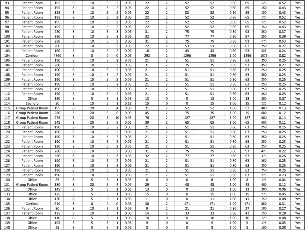
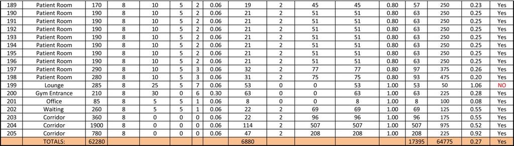
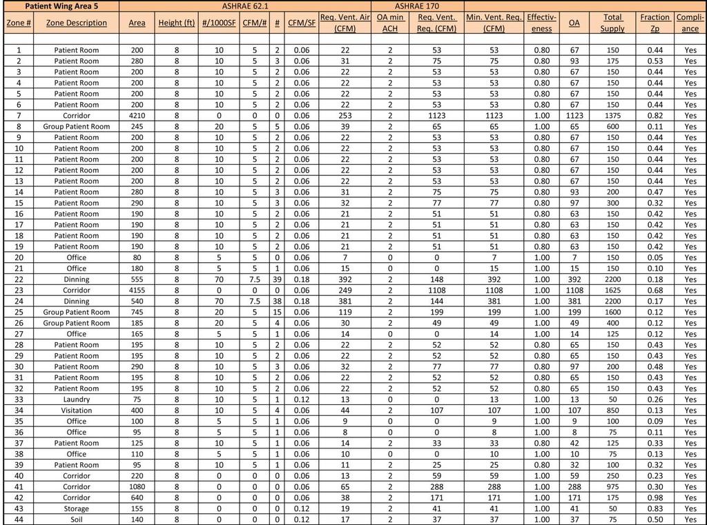
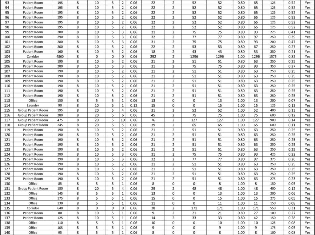
12 modulate the chilled water valve in order to call for cooling. When the outside air temperature is below than 65 F, the return damper would be fully opened and modulate the chilled water control valve to call for cooling. When the outside air temperature is below than the supply air temperature set point, the chilled water sensor becomes deactivated in order to maintain the supply air temperature set point. When the outside air temperature is below than the supply air temperature, the outside air damper would be positioned at the minimum position and the return damper would be opened. The ASHRAE weather data and design conditions of the project are described in Table 1 and Table 2. Table 2: Design Temperature VENTILATION REQUIREMENTS The ventilation requirements and calculation on the Northfield Mental Healthcare center were performed and described in the technical report 1. Both the existing conditions and newly designed conditions were considered, since the project is both renovation and expansion. The spaces that are not required for the minimum ventilation were omitted for the ventilation calculation analysis. The entire building is served by ten different air handlers, but five of them contribute on the occupied spaces, another two contribute on the energy center, and the 11

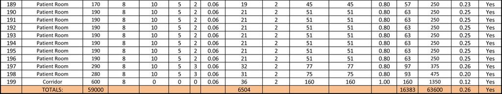
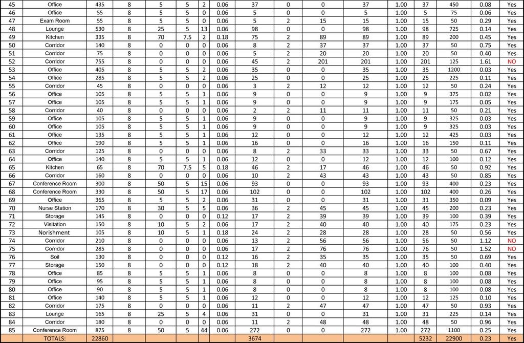
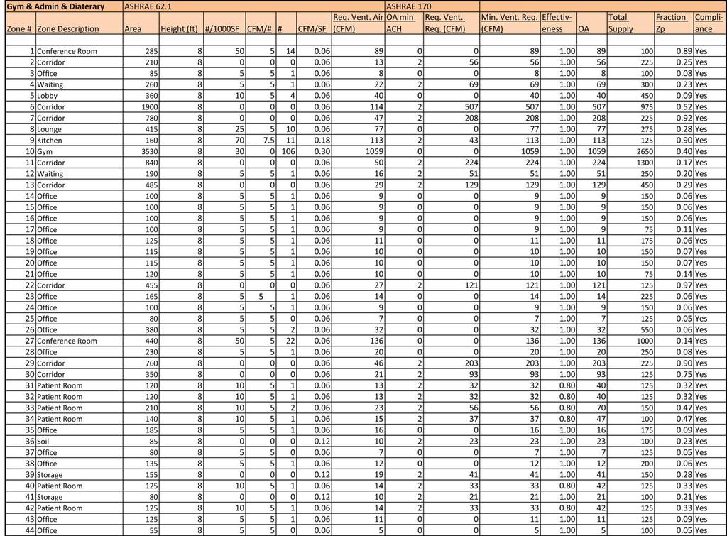
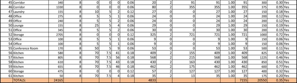
13 other two existing air handlers contribute on the renovated areas. Air handler 1 and 2 are designed to supply 65,000 CFM to each newly designed patient wing with designed outdoor airflow of 20,000 CFM. The minimum outdoor airflow requirement in accordance of the ASHRAE Standard 62.1 was calculated to be 17,500 CFM and 16,500 CFM respectively for the left patient wing and the right patient wing. The designed outdoor airflow values for air handler 1 and 2 are more than the minimum outdoor air requirements, thus they comply with ASHRAE Standard The total outdoor air flow required for the gym, clinic/admin, and dietary areas were calculated to be approximately 72,000 CFM total which is under the designed outdoor airflow of 12,500 CFM total. Since there was a lack of information on the outdoor airflow of the existing air handlers, compliance for the existing air handlers were unknown. Table 3 shows a summary of comparisons between the designed supply and outdoor airflows and the calculated minimum requirements. Table 3: Summary of Ventilation Calculations Most of the ventilation loads and their equipment were oversized for the safety and better efficiencies. Oversized outdoor airflow provides better indoor air quality for the 12
14 building. The detailed calculations on the required outdoor airflows are attached to the Appendix A MECHANICAL EQUIPMENT SUMMARY Except for the air handler 3, all the air handlers used for the newly designed spaces are outdoor roof top units consisting of VFD return fan, 30 % economizer, pre-filters, afterfilter, heating water preheat coil, chilled water coil, supply fan, and sound attenuator. The air handler 1 and 2 serve the left patient wing and the right patient wing respectively. The air handler 3 has the same unit construction but is an indoor air handling unit located in Gymnasium area with 100% of heat recovery system. The air handler 4 and 5 serve admin/clinic area and dietary area respectively. The air handler 6, 7, and 8 are indoor units and are located in the energy center. Most of the air handlers used for the building are variable air volume models except for the air handler 1 and 2 which are custom model and the air handler 3 which is constant volume model. The entering air temperatures and leaving air temperatures of cooling and heating of each air handler are listed in Table 4. Internal supply fans used for each air handler are described in Table 5. 13


15 Table 4: Air Handling Unit Cooling and Heating Schedule Table 5: Air Handling Unit Supply Fan Schedule There are five major types of exhaust fans used for this project: patient room exhaust, general exhaust, emergency exhaust, boiler room exhaust, and kitchen exhaust hood. The general exhaust fans run continuously, and exhaust dampers are controlled by the digital control panels. Expansion modules are required for those digital control panels. Two EF-1 and one EF-2 are located on the roof of each patient wing. EF-3 is used for gym area and admin/ clinic area, and EX-4 is located on the roof above the trash holding area. EF-5, 6, and 7 are located above kitchen hood on the roof; Kitchen exhaust hood is directly ducted through roof structure and will not be recirculated. 14

16 Table 6: Return and Exhaust Fan Schedule Chilled water is generated from the cooling tower and transferred to two chillers located in the energy center. The flow rate of the chilled water is controlled by DDC controller which measures the supply and return temperature as well as differential pressure transmissions across the chilled water pumps. The chilled water is then circulated to air handling units and distributed to the entire building. Hot water is generated from the six boilers located in the energy center. The boilers provide heating, preheating, and reheating water. Heating water return temperature is controlled by DDC controller, and the hot water is served by six primary heating water pumps and two secondary heating water pumps; the primary heating water pumps serve boilers and the secondary heating water pump serve the heating load. The boiler schedule, chiller schedule, and pump schedule are described in Table 7, Table 8, and Table 9 respectively. 15


17 Table 7: Boiler Schedule Table 8: Chiller Schedule Table 9: Pump Schedule 16

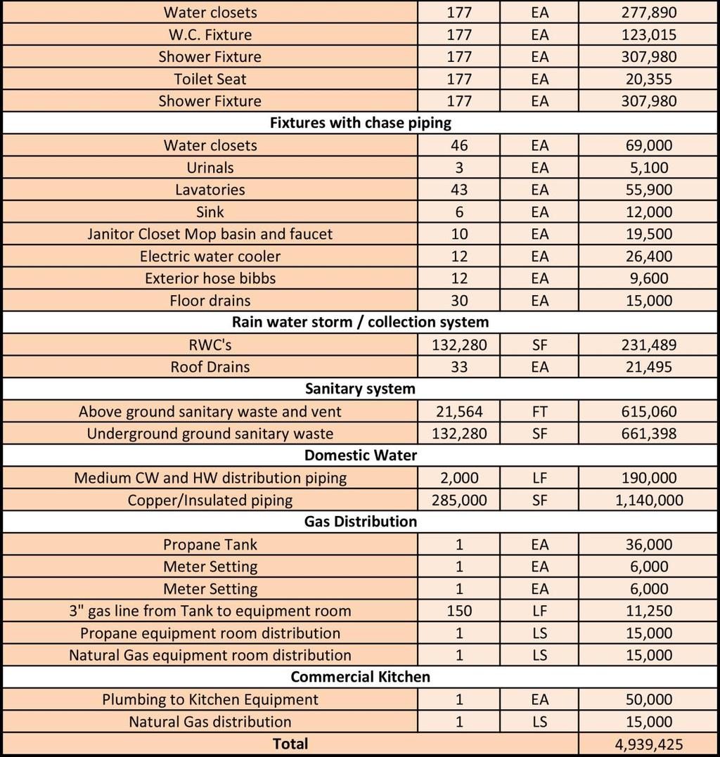
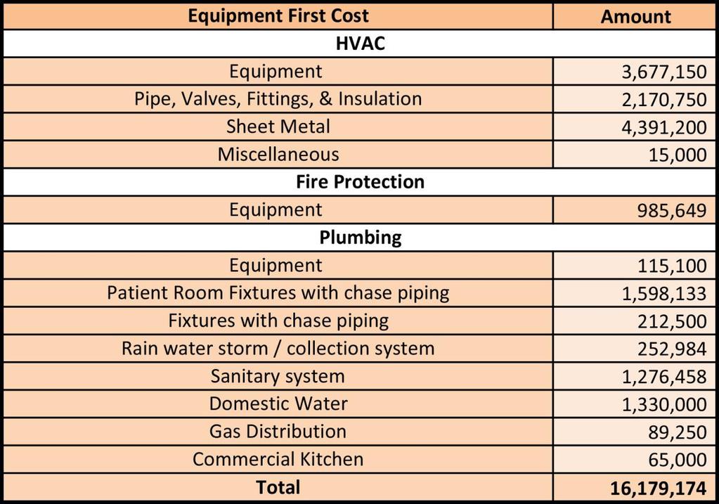
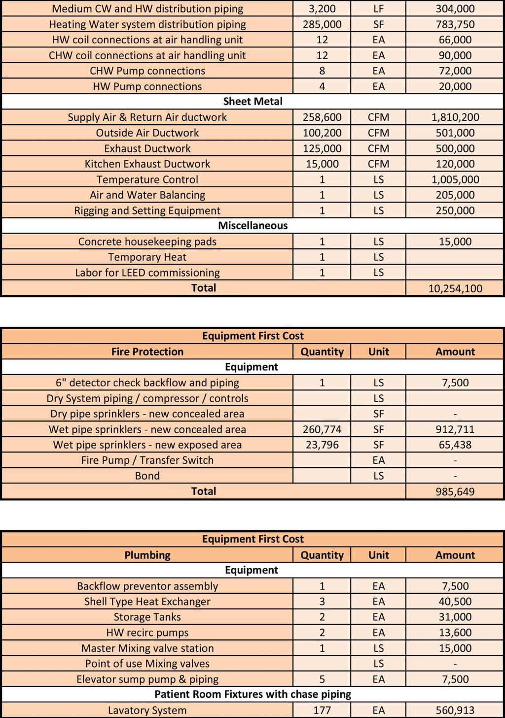
18 1.3.4 MECHANICAL FIRST COSTS Table 10 shows breakdown of first costs for HVAC systems, fire protection equipment, and plumbing equipment according to a report produced by the contractor. The costs include the costs of equipment, installation, material used for the equipment, and miscellaneous. The total estimated cost is approximately $16,180,000 with a cost per square foot of $81.00 / SF. The detailed cost breakdown is described in Appendix B. Table 10: First Cost Summary LOST USABLE SPACE Table 11 shows breakdown of unusable spaces. Common areas for unusable spaces are mechanical rooms and electrical rooms. Existing building portions were also taken an 17

19 account for this analysis. The big mechanical room located on the basement of existing building takes a majority of unusable space for the entire building. 1.4 SYSTEM OPERATION Table 11: Lost Usable Space AIR SIDE OPERATION As mentioned above, five air handlers and two existing air handlers supply the building with heating, ventilation and air conditioning, and the other three air handlers supply the energy center. Air handler 1 and 2 produce almost 10 times greater supply air than the other air handlers and supply air to both patient wings. Each air handling unit is equipped with a VFD return fan, a 30 % economizer, a pre-filter, after-filter, a preheat coil, a chilled water coil, a supply fan, and a sound attenuator in a sequence. Variable frequency drives are equipped for both supply fan and return fan installed inside of air handling units. Figure 3 is the air handling unit control diagram. The supply airflow and air temperatures are controlled by modulating various damper positions and the variable frequency drives depending on the measured supply air 18
20 temperature at the highlighted sensors. Cooling operation is called when the outside air temperature sensed by the BAS is between 65 F and the supply air temperature set point by modulating the return dampers as fully closed and the relief damper as fully opened. Heating operation is called when the outside air temperature is below the supply air temperature set point by modulating outdoor air damper and relief air damper to be at the minimum position. The return fans are operating when supply fans are operating. When the supply fans stop operating, the return fans automatically stop operating as well. If a supply fan or a return fan fails to be operated, the system will generate alarm. Figure 3: Schematic Drawing of Airflow WATER SIDE OPERATIONS Chilled water is generated and served from the cooling towers to chillers through tower pumps. A three way modulating valve equipped inside of the tower controls the water flow rate through the chillers. DDC controller is used for controlling operations of the 19
21 chillers. DDC controller determines the cooling load by measuring the supply and return temperatures and differential pressure transmissions across the chilled water pumps. The chilled water is also distributed to the air handling units through cooling coils. When the outdoor air temperature is below than a certain point, for example 45 F, the chiller water system will be inactivated until the outdoor air temperature rises above 50 F. Figure 4 shows the chilled water flow diagram. Figure 4: Chilled Water Flow Diagram 20
22 The hot water is generated from six boilers which are located in the energy center. The hot water flow rate is controlled by the DDC controller. The boilers provide heating, preheating and reheating water. DDC controller connected to each boiler monitors the heating water return temperature and alarms if the temperature difference between the supply and the return water exceed a certain point. With a capacity of HP, each boiler uses natural gas as a fuel and has gas fired burner. Water is delivered through vertical inline pumps with capacity of 190 GPM to each boiler. There are total six primary heating water pumps and two secondary heating water pumps; the primary heating water pumps serve boilers and the secondary heating water pump serve the heating load. Figure 5 shows the heating water flow diagram. Figure 5: Heating Water Flow Diagram 21


23 1.4.2 MODEL DESIGN Each of the 1130 rooms was input into the TRACE model. Each room was designated with different internal loads and airflow assumptions, depending upon the primary space use and occupancy. Restrooms and small storages were neglected. All the exterior walls, windows, as well as doors with their orientations, were input in order to calculate envelope loads for each space. Lighting and electrical load, occupancy and airflow assumptions, as well as construction for the building envelope, are described in the following sections. All of the input rooms were then assigned to 20 different zones, all of which have their own temperature controls. Multiple zones, served by an air-handling unit, were bounded together and assigned to a system. Figure 6 shows how the zones are assigned to a system. Figure 6: TRACE Energy Model Zoning 22
24 1.4.3 LIGHTING AND EQUIPMENT ELECTRICAL LOAD ASSUMPTIONS 24 different templates were created for each of the various space types, which all have assumed lighting and miscellaneous equipment power density values. The assumptions on lighting power density were taken from ASHRAE Standard The assumptions on miscellaneous equipment power density are based on nameplate ratings from electrical equipment. Table 12 shows a summary of lighting and electrical load assumptions. Space Type LPD (W/SF) Miscellaneous Loads (W) Conference Room Corridor Exam Room Gym Kitchen W/SF Lobby Locker Room Lounge Nurse Station Office Patient Room Storage Table 12: Lighting and Electrical Load Assumptions OCCUPANCY ASSUMPTIONS The number of occupants, per square feet, is assumed based on Table 6-1 of ASHRAE The occupancy densities that were not listed in Table 6-1 were estimated based on the number of furniture shown in architectural plans. Table 13 shows the occupancy assumptions used for the TRACE model. 23
25 Space Type Occupancy Density (#/1000SF) (SF/#) Conference Room Corridor 0 0 Exam Room 25 2 people Gym Kitchen Lobby Locker Room 6 people Lounge Nurse Station 30 3 people Office Patient Room Storage 0 0 Table 13: Occupancy Assumptions AIRFLOW ASSUMPTIONS The minimum ventilation rates, for each space type, were obtained from ASHRAE Standard The amount of infiltration for hospital spaces were obtained from ASHHRAE Standard 170. The minimum ventilation rate based on the number of people, the minimum ventilation rate based on square feet, and infiltration values are listed on Table
26 Space Type Minimum Minimum Ventilation Ventilation Rates Rates (CFM/#) (CFM/SF) Infiltration (ACH) Conference Room Corridor 2 CFM 2 CFM 0.6 Exam Room 2 CFM 2 CFM 0.3 Gym Kitchen Lobby Locker Room 4 CFM 4 CFM 0.6 Lounge Nurse Station 2 CFM 2 CFM 0.6 Office Patient Room Storage Table 14: Airflow Assumptions CONSTRUCTION OF BUILDING ENVELOPE The Northfield Mental Healthcare Center is designed with four different wall types and one roof type. However, only one type of wall, roof, and window was used for the analysis, for simplification. U-values for the wall, roof, and window were taken from construction documents and are listed on Table 15, Table 16, and Table 17. Walls R-value Thicknes (ft) Conductivity Surface Air Film (Vertical) Common 4" Brick Air Layer 3/4" to 4" (Vertical) " Insulation /2" Gypsum or Plaster Board Mineral Wool/Fiber, Batt, R /8" Gypsum or Plaster Board Overall R-Value Overall U-Value Table 15: Exterior Wall Construction 25
27 Roof R-value Outside Film /2" Polyiso Rigid " Spray Fire Proof Inside Film Overall R-Value Overall U-Value Table 16: Roof Construction Windows Overall U-Value SHGC Shading Coefficient Table 17: Window Construction DESIGNED TEMPERATURE CONTROL A programmable temperature controller attains the temperature for supply air, to a space. Table 2 shows designed temperature set points for each air handler. The supply air temperature would be maintained, at a set point, by modulating the economizer control damper and valve positions. The supply air temperature set point is linearly reset in a range of 5 F, as supply air can be set at a minimum temperature of 55 F. When room temperature indicates below 70 F, the controller would be deactivated. When the mixed air temperature hits below 40 F, the outside air damper would be closed and the return air damper would be opened. When the outside air temperature is between 65 F and the supply air temperature set point, the return air damper would be fully closed. Additionally, the outside air damper would be positioned at the maximum outdoor air economizer position, and the digital 26
28 panel would modulate the chilled water valve in order to call for cooling. When the outside air temperature is below 65 F, the return damper would fully open and modulate the chilled water control valve to call for cooling. When the outside air temperature is below the supply air temperature set point, the chilled water sensor would deactivate in order to maintain the supply air temperature set point. When the outside air temperature is lower than the supply air temperature, the outside air damper would be positioned at the minimum position and the return damper would be opened. 1.5 ENERGY MODELING - OUTPUT COOLING, HEATING, AND VENTILATION LOAD Load calculations of the Northfield Mental Healthcare Center, calculated by the engineer of the project, were performed by utilizing the CHVAC program. The CHVAC energy model created by the engineer might use different assumptions for lighting and electrical load, occupancy, and airflow, as well as different methods to separate rooms into zones. Also, the outputs of the CHVAC energy model was re-evaluated by using their own excel program to balance with the minimum outdoor airflow required for the hospital, as well as to take account of the reheating process. The summary of load calculations, provided by the engineer of the project and the output of the TRACE model, is described in 27
29 Table 18. ZONES Design TRACE Cooling (Btu/hr) Heating (Btu/hr) Ventilation (CFM) Cooling (Btu/hr) Heating (Btu/hr) Ventilation (CFM) AHU-1 Patient Wing (Right) 2,871,500 2,128,464 65,000 2,565,694 3,565,409 57,377 AHU-2 Patient Wing (Left) 2,871,500 2,128,464 65,000 2,601,886 3,631,777 59,361 AHU-3 Gym 172, ,690 3, , ,633 2,832 AHU-4 clinic/admin 338, ,150 7, , ,731 9,314 AHU-5 Dietary 320, ,510 7, , ,020 9,430 AHU 6 boiler plant - 488,020 - AHU 7 Chiller plant - 488, ,002 - AHU 8 Electrical Room 262, , , ,323 - AHU-9 Existing A/B 2,900,000 1,250,000 70,000 3,027,007 2,119,661 64,056 AHU-10 Existing C 600, ,000 14, , ,479 13,044 Reheat Total Tons MBH - 4,230, ,337,310 12,306, ,325 10,002,193 11,180, , ,306 11,180 Table 18: Design Load Values VS. Calculated Load Values The cooling load, heating load, and ventilation load, calculated by the engineer, seem to be larger than the output of the TRACE model. The comparison of loads, by zones, is unnecessary because zones are divided in a different manner. The difference between the engineer s design values and the TRACE output values is within 10 percent. The major difference can be found in the heating load. A possible reason, for the cause of the difference, is that the reheating process was considered in the CHVAC model. The cooling load and heating load outputs of the TRACE model are 834 tons and 11,180 MBH, respectively. These outputs will be used for mechanical alternatives analyses. Table 19 contains a summary of load comparisons and differences in loads between the CHVAC model and TRACE model. Cooling (Btu/hr) Heating (Btu/hr) Ventilation (CFM) Design 10,337,310 12,306, ,325 TRACE 10,002,193 11,180, ,414 Difference 335,117 1,126,203 16,911 Difference (%) (Underestimated) (Underestimated) (Underestimated) Table 19: Cooling Load, Heating Load, and Ventilation Load Summary 28
30 1.4.2 DOMESTIC HOT AND COLD WATER LOAD The need of domestic cold water and hot water for plumbing fixtures was also estimated by counting plumbing fixtures, which are located in the building. Table 20 shows calculations on the amount of domestic hot and cold water needed. Since all the plumbing fixtures do not run for whole time, the domestic hot water demand was estimated to be 25% of the total hot water needed for plumbing fixtures. The temperature of makeup water entering the domestic water heater was assumed to be at 40 F, and the temperature of hot water leaving the domestic water heater was assumed to be at 140 F. Based on these assumptions, the total energy consumption for producing domestic hot water was calculated and summarized on Table 21. FIXTURE TYPE COUNT HW FIXTURE UNIT HW (GPH) CW FIXTURE UNIT CW (WSFU) Water Closet ,840 Urinal Lavatory , SINK Mop Basin Shower , Washing Machine TOTALS 8,319 3,994 TOTAL HW NEED (GPM) 139 TOTAL CW NEED (GPM) 3,994 Table 20: Domestic Water Needs Calculation 29
31 Domestic Hot Water: Energy Consumption EWT (F) 40 LWT (F) 140 DELTA T (F) 100 HW DEMAND (GPH) -25% 2,080 INPUT RATE (BTUH) 2,165,540 OUTPUT RATE (BTUH) 1,732,432 GAS DEMAND (CFH) 2, HW STORAGE TANK (GAL) 1,248 Table 21: Domestic Hot water Energy Consumption 1.6 ENERGY CONSUMPTION The total energy consumption was calculated based on the outputs of the TRACE model. Since the energy consumption rates of mechanical equipment were estimated, based on the general consumption rate specified either on product catalogs or specifications, the actual energy consumption of the mechanical equipment can differ from the estimated total energy consumption given by the TRACE model. Table 22 contains a summary of total annual electricity and gas consumption. Summary of Load Calculation and Energy Consumption Calculation Total SF (SF) 260,000 Cooling (TONS) 834 Space Heating (MBH) 11,180 Chilled Water Difference 1,820 Hot Water 40F Difference 559 Domestic Hot Water (GPM) 139 Total Energy Consumption (KWh) 32,779,802 Total Electricity Consumption (KWh) 14,127,906 Total Natural Gas Consumption (Therms / yr) 636,589 Table 22: Summary of Load Calculation and Energy Consumption Calculation 30

32 Energy Usage Breakdown of the TRACE model is described on Table 23. Space cooling requires almost 33% of the total electricity consumption, and space heating requires almost 85% of the total gas consumption. Figure 7 and Figure 8 show electricity consumption breakdowns and natural gas consumption breakdowns, respectively. Multiple ways to reduce energy consumption breakdowns used for the space cooling and heating will be studied in the section two of this report. Energy Usage Breakdown Electricity (%) Gas (%) Heating Cooling Lighting Equipment Fans Pumps Other Heating Equipment Water System Table 23: Energy Usage Breakdown Figure 7: Electricity Usage Breakdown 31

33 Figure 8: Natural Gas Usage Breakdown Based on the estimated energy consumption, energy use index was calculated and summarized on Table 24. The EUI values are calculated based on energy consumption with a full load performance. Table 25 describes the typical EUI values of the hospital model, with base load performance, in climate Zone 5A. If a demand factor is applied for the TRACE model, the EUI value will be calculated much closer to the typical EUI value of the hospital model with baseline performance. Electricity EUI Natural Gas EUI EUI EUI Value Calculated 185 kbtu/sf 250 kbtu/sf 435 kbtu/sf Table 24: Calculated EUI Values EUI Value of Typical Hospital (Baseline Model) EUI 388 kbtu/sf Table 25: EUI Value of Typical Hospital 32
34 1.7 EMISSION Emissions from the energy usage were calculated using emission factors from the Regional Grid Emissions Factors 2007 file. Table 26 shows the mass of each pollutant produced by electricity usage for this building. Emission for Delivered Electricity Precombustion Emission for Delivered Natural Gas On-Site Combustion Emission for Boiler Factor Mass of Pollutant Factor Mass of Pollutant Factor Mass of Pollutant Total Pollutant lb/ kwh lb lb/ ft^3 lb lb/ ft^3 lb lb CO2e 1.74E E E E E E E+08 CO2 1.64E E E E E E E+08 CH4 3.59E E E E E E E+05 N2O 3.87E E E E E E E+03 NOx 3.00E E E E E E E+05 SOx 8.57E E E E E E E+06 CO 8.54E E E E E E E+05 TNMOC 7.26E E E E E E E+03 Lead 1.39E E E E E E E+00 Mercury 3.36E E E E E E E+00 PM E E E E E E E+04 Solid Waste 2.05E E E E E E E+07 Table 26: Emission Calculation 1.8 LEED ANALYSIS The Northfield Mental Healthcare Center did not aim for a LEED certification. The building, however, utilizes some of the sustainable features, such as a highly insulated exterior envelope, efficient equipment, programmable temperature controllers, and occupancy sensors. Even if this facility was not designed to be LEED certified, a simple LEED analysis was conducted for this report for future reference. This analysis would be 33
35 helpful to see how many more LEED points are required in order for the building to be LEED certified, if this building will attempt to become a LEED certified building in the future. The LEED 2009 rating system for New Construction and Major Renovations was used for this analysis. In order to obtain the LEED basic, at least 40 points are required. Since there was insufficient information about the building systems, several points were analyzed ambiguously ENERGY AND ATMOSPHERE EA Prerequisite 1: Fundamental Commissioning of Building Energy Systems (Required) Intent: To verify that the project s energy-related systems are installed and calibrated to perform according to the owner s project requirements, the basis of design, and construction documents. Commissioning process activities must be completed by the project team in order to achieve this point. The Northfield Mental Healthcare Center is not constructed yet, so this point would be a pending point. EA Prerequisite 2: Minimum Energy Performance (Required) Intent: To establish the minimum level of energy efficiency for the proposed building and systems, in order to reduce environmental and economic impacts associated with excessive energy use. 34
36 The Northfield Mental Healthcare Center complies with the mandatory provisions in ASHRAE EA Prerequisite 3: Fundamental Refrigerant Management (Required) Intent: To reduce stratospheric ozone depletion. Chlorofluorocarbon (CFC) is not used for any of the HVAC systems at the Northfield Mental Healthcare Center. EA Credit 1: Optimize Energy Performance (2 Points) Intent: To achieve increasing levels of energy performance beyond the prerequisite standard, in order to reduce environmental and economic impacts associated with excessive energy use. Based on the energy consumption performed by the engineer, it can be assumed that 14% of energy reduction is achievable and eligible to obtain 2 points INDOOR ENVIRONMENTAL QUALITY IE Q Prerequisite 1: Minimum Indoor Air Quality Performance (Required) 35
37 Intent: To establish minimum indoor air quality (IAQ) performance to enhance indoor air quality in buildings, thus contributing to the comfort and well-being of the occupants. Mechanical ventilation systems for the Northfield Mental Healthcare Center were designed using the ventilation rate procedure. IE Q Prerequisite 2: Environmental Tobacco Smoke (ET S) Control (Required) Intent: To prevent or minimize exposure of building occupants, indoor surfaces, and ventilation air distribution systems from environmental tobacco smoke (ETS). The Northfield Mental Healthcare Center prohibits smoking in the building and prohibits on-property smoking within 25 feet of entries. IE Q Credit 2: Increased Ventilation (1 Point) Intent: To provide additional outdoor air ventilation in order to improve indoor air quality (IAQ) and promote occupant comfort, well-being, and productivity. The Northfield Mental Healthcare Center mostly deals with mechanically ventilated spaces, and outdoor air ventilation rates for breathing zones were increased by at least 30% above the minimum rates required by ASHRAE Standard IE Q Credit 5: Indoor Chemical and Pollutant Source Control (1 Point) 36
38 Intent: To minimize exposure to potentially hazardous particulates and chemical pollutants. The air-handling units used in the Northfield Mental Healthcare Center consist of pre- filters and final-filters, with a minimum of MERV 13. The hazardous areas that use hazardous gases or chemicals are sufficiently exhausted. IE Q Credit 6.2: Controllability of Systems Thermal Comfort (1 Point) Intent: To provide a profusion of thermal comfort systems that can be controlled by individual occupants or groups in multi-occupant spaces (e.g., classrooms or conference areas) and to promote their productivity, comfort, and well-being. The Northfield Mental Healthcare Center provides comfort system controls for all shared multi-occupant spaces in order to achieve individual occupants or groups thermal comforts. IE Q Credit 7.1: Thermal Comfort Design (1 Point) Intent: To provide a comfortable thermal environment that promotes occupant productivity and well-being. The Northfield Mental Healthcare Center is equipped with a BAS, which monitors thermal conditions, inclusive of temperature and air speeds. 1.9 OVERALL EVALUATION SUMMARY 37
39 The mechanical systems of the Northfield Mental Healthcare Center comply with the mandatory provisions in ASHRAE Standards, but the maximum efficiencies of the systems were not achieved due to project budget issues. Some of the energy efficiencies were achieved by equipping programmable temperature controllers, occupancy sensors, BAS controllers, and variable frequency-derive controllers. Increasing outdoor air intake for mechanical ventilation and equipping pre-filters and finalfilters inside of each air-handling unit accomplishes indoor air quality for the Northfield Mental Healthcare Center. Even if routine maintenance is required for those filters and results in higher maintenance costs, those installed filters result in longer equipment life. VAV systems will also enhance the higher indoor air quality of the building; varying the supply air volume will reduce the building energy usage by reducing work done by fans, but it will still increase indoor air quality by producing a very little margin of error from desired temperatures. In addition, VAV systems enable the individually controlled zones to have their own thermostats, which can control their thermal comfort by adjusting the controller. The cooling and heating loads are also efficiently served by using condensing boilers and electric centrifugal chillers. Also, VFD, installed in pumps and fans, saves energy by controlling their outputs based on the needs of occupants. However, adapting more efficient heating and cooling systems or on-site energy generation systems can reduce high annual total energy consumption. The approximate construction cost is $62.5 million for the entire project and $312.5 /SF. According to the commercial real estate specialists online resources, this cost lies in 38

40 the mid-high region of the range. Figure 9 shows the construction cost per square foot, for a 4 to 8 story hospital. The first cost, including the costs of equipment, installation, material used for the equipment, and miscellaneous, was calculated to be $81.00 / SF. The first cost of the HVAC equipment, fire protection equipment, and plumbing equipment seems to be average when compared to hospital projects of a similar size. Figure 9: Construction Cost per Square Foot for 4 to 8 Story Hospital Based on the construction cost, the first installation cost, and performance of the systems, this project is reasonably well designed. The annual operating and fuel costs for all of the mechanical equipment, however, seem to be higher than that of typical, large hospitals. A reduction of annual operating and fuel costs will be the primary consideration of this thesis project. 39
41 1.10 REFERENCE Figure 9: "Cost per Square Foot For New Commercial Construction." The Commercial Real Estate Specialists ONLINE RESOURCES. The Commercial Real Estate, n.d. Web. 12 Nov < 40

42 APPENDIX A: The Minimum Outdoor Airflow Requirement in Accordance of the ASHRAE Standard 62.1 and the ASHRAE Standard
43 42
44 43
45 44
46 45
47 46
48 47
49 48
50 49
51 50
52 51

53 APPENDIX B: Mechanical First Costs 52
54 53
55 54
56 55
Technical Report Three
 Technical Report Three Existing Conditions for Mechanical Systems Contents Executive Summary...2 Building Overview...2 Mechanical Systems Overview...2 Mechanical System...3 Outdoor & Indoor Design Conditions...3
TECHNICAL REPORT 3: Mechanical Systems and Existing Conditions. Michael Morder Mechanical Option Advisor: Dr. William Bahnfleth
 TECHNICAL REPORT 3: Mechanical Systems and Existing Conditions Michael Morder Mechanical Option Advisor: Dr. William Bahnfleth INOVA South Patient Tower Falls Church, VA November 16, 2011 Table of Contents
11/2 ORT THREEE. Virtua Repla. acement Hospi. ital. Voorhees NJ. Justin Prior. Mechanical
 11/2 29 Virtua West Jersey Repla acement Hospi ital Voorhees NJ TECHNICAL REPO ORT THREEE System Overview Justin Prior Mechanical Table of Contents Executive Summary 3 System Overview 4 Design Factors
Andrea Borowski The Pennsylvania State University University Park, PA November 11, 2002 Consultant: Dr. Bahnfleth Technical Assignment M-3
 Existing System Evaluation Executive Summary The MBNA Career Services Center is a 44,000 square foot, 4-story office type building at Penn State University, University Park Campus. The building is located
Christopher Kelly Technical Report Three
 Christopher Kelly Technical Report Three Mechanical Systems and Existing Conditions Evaluation SALK HALL ADDITION The University of Pittsburgh, Pittsburgh Christopher Kelly, Mechanical Option Professor
Technical Report #3 Mechanical Systems Existing Conditions Evaluation
 Mechanical Option Technical Report #3 Technical Report #3 Mechanical Systems Existing Conditions Evaluation Instructor: Dr. Bahnfleth 11.15.04 Building Sponsor: CCG Facilities Integration Table of Contents
(2.1) Design Conditions...5 (2.2) Ventilation Requirements..5 (2.3) Heating and Cooling Loads...6
 Design Conditions...5 (2.2) Ventilation Requirements..5 (2.3) Heating and Cooling Loads...6") TECHNICAL REPORT 3 MECHANICAL SYSTEMS EXISTING CONDITIONS EVALUATION New Braunfels Regional Rehabilitation Hospital Adam Bernardo Mechanical Option Faculty Advisor: Dr. William Bahnfleth Date Submitted:
TECHNICAL REPORT 3 MECHANICAL SYSTEMS EXISTING CONDITIONS EVALUATION New Braunfels Regional Rehabilitation Hospital Adam Bernardo Mechanical Option Faculty Advisor: Dr. William Bahnfleth Date Submitted:
The Ed Roberts Campus
 The Ed Roberts Campus Technical Report 3 Anderson Clemenceau Mechanical Option Advisor: Donghyun Rim November 11, 2014 2 Contents Technical Report 3... 1 Executive Summary... 3 Building Overview... 4 Design
Technical Assignment 3 11/15/04. Executive Summary
 Executive Summary This report is an analysis of the existing systems within the Outreach Innovation Building in University Park, PA. One significant design criteria was a lower than average noise criteria
Mechanical Technical Report 3. Mechanical Systems Existing Conditions Evaluation
 Mechanical Technical Report 3 Lutheran Theological Seminary at Philadelphia The New Learning Center Prepared For: William P. Bahnfleth, Ph.D., P.E. Department of Architectural Engineering Pennsylvania
1080 Marina Village Parkway, Suite 501 Alameda, CA (510) Fax (510) HVAC DESIGN INTENT
 Fax (510) HVAC DESIGN INTENT") Taylor Engineering 1080 Marina Village Parkway, Suite 501 Alameda, CA 94501-1142 (510) 749-9135 Fax (510) 749-9136 LLC HVAC DESIGN INTENT PART 1 - GENERAL 1.1 Overview A. The project consists of a 3-story
Taylor Engineering 1080 Marina Village Parkway, Suite 501 Alameda, CA 94501-1142 (510) 749-9135 Fax (510) 749-9136 LLC HVAC DESIGN INTENT PART 1 - GENERAL 1.1 Overview A. The project consists of a 3-story
Technical Investigation, Part Three Elizabeth C. Krauss Mechanical Option September 18, 2013
 Technical Investigation, Part Three Elizabeth C. Mechanical Option September 18, 2013 State Institute of Rehabilitation T e c h n i c a l R e p o r t I 1 Technical Investigation, Part Three... 0 Executive
The Creative and Performing Arts High School (CAPA) Pittsburgh, PA 11/11/2002 Andrew Tech Mechanical Option Prof. S. A. Mumma
 Pittsburgh, PA 11/11/2002 Andrew Tech Mechanical Option Prof. S. A. Mumma") Objectives and Requirements For the Creative and Performing Arts High School (CAPA), the main objective of the mechanical design is to provide an energy efficient system that is easily maintainable and
Objectives and Requirements For the Creative and Performing Arts High School (CAPA), the main objective of the mechanical design is to provide an energy efficient system that is easily maintainable and
Inspection Phase Three. Mechanical, Electrical & Plumbing Section 503
 Inspection Phase Three Mechanical, Electrical & Plumbing Section 503 COMCheck Mechanical Field Inspection Checklist Mechanical Mechanical, Electrical & Plumbing Equipment Efficiencies But a lot ore too
4. OVERVIEW OF MECHANICAL SYSTEM
 4. OVERVIEW OF MECHANICAL SYSTEM The 87,000 SF SLCC is served by six (6) Trane M-Series Climate Changer Air Handing Units (AHUs). Each unit serves a distinct zone within the facility that is unique in
Architectural Engineering Senior Thesis Mechanical System Redesign
 Saint Joseph Medical Center Architectural Engineering Senior Thesis Mechanical System Redesign Chris Nicolais Building Description Existing Mechanical System Proposed Redesign Alternative Option Emergency
SECTION HVAC TABLE OF CONTENTS PART 1 - SYSTEM DESCRIPTION / OUTLINE SPECIFICATIONS FILED SUB BID PROJECT OVERVIEW...
 SECTION 230001 TABLE OF CONTENTS SECTION 230001 PART 1 - SYSTEM DESCRIPTION / OUTLINE SPECIFICATIONS... 1 1.00 FILED SUB BID... 1 1.01 PROJECT OVERVIEW... 2 1.02 DESIGN CRITERIA... 4 1.03 CODE ISSUES...
UNIVERSITY OF MISSOURI Heating Ventilating and Air-Conditioning (HVAC) 2016 Q1
 2016 Q1") GENERAL: This section provides general standards for overall sizing and design of Heating, Ventilating, and Air Conditioning (HVAC) systems. Other sections contain specific standards for each system per
GENERAL: This section provides general standards for overall sizing and design of Heating, Ventilating, and Air Conditioning (HVAC) systems. Other sections contain specific standards for each system per
Mechanical Technical Report 1. ASHRAE Standard 62.1 Ventilation Compliance Evaluation
 Mechanical Technical Report 1 Standard 62.1 Ventilation Compliance Evaluation Lutheran Theological Seminary at Philadelphia The New Learning Center Prepared For: William P. Bahnfleth, Ph.D., P.E. Department
EADQUARTERS. Technical Report One. Stephanie Kunkel Mechanical Option
 EADQUARTERS 707 N. Calvert St. Technical Report One ASHRAE Standard 62.1 Ventilation ASHRAE Standard 90.1 Energy Design Stephanie Kunkel www.engr.psu.edu/ae/thesis/portfolios/2011/slk5061 Mechanical Option
ASHRAE Illinois Chapter 2015 Excellence in Engineering Awards
 ASHRAE Illinois Chapter 2015 Excellence in Engineering Awards PROJECT Chicago Vocational Career Academy Chicago, Illinois OWNER Chicago Public Schools PREPARED FOR American Society of Heating Refrigerating
Madeira City Schools Madeira, Ohio. HVAC Assessment. December 2011 (Revised February 2012)
") Madeira City Schools Madeira, Ohio HVAC Assessment December 2011 (Revised February 2012) Prepared by: CMTA Engineering Consultants, Inc. 10411 Meeting Street Prospect, KY 40059 www.cmtaegrs.com (502) 326-3085
Madeira City Schools Madeira, Ohio HVAC Assessment December 2011 (Revised February 2012) Prepared by: CMTA Engineering Consultants, Inc. 10411 Meeting Street Prospect, KY 40059 www.cmtaegrs.com (502) 326-3085
Computing Services Center
 Continuous Commissioning Report for the Computing Services Center Building #516 Submitted to: Utilities Energy Office Physical Plant Department Texas A&M University Prepared by: Energy Systems Laboratory
SECTION SEQUENCE OF OPERATIONS FOR HVAC CONTROLS
 PART 1 - GENERAL SECTION 23 09 93 SEQUENCE OF OPERATIONS FOR HVAC CONTROLS 1.1 SUMMARY A. This Section includes control sequences for HVAC systems, subsystems, and other equipment. B. See Division 23 Section
SECTION SEQUENCE OF OPERATIONS FOR HVAC CONTROLS
 SECTION 23 09 93 SEQUENCE OF OPERATIONS FOR HVAC CONTROLS PART 1 - GENERAL 1.1 SUMMARY A. This Section includes control sequences for HVAC systems, subsystems, and equipment. B. See Division 23 Section
High Performance Building Guide 1
 Description This Guide is intended to be used for projects with a Vermont Certified: High Performance energy efficiency goal. This High Performance goal is a whole-building efficiency approach rather than
INTRODUCTION TO: ASHRAE STANDARD 90.1, HVAC System Requirements for Reducing Energy Consumption in Commercial Buildings
 INTRODUCTION TO: ASHRAE STANDARD 90.1, 2013 HVAC System Requirements for Reducing Energy Consumption in Commercial Buildings Rocky Mountain ASHRAE Technical Conference, April 29, 2016 SEAN BEILMAN, P.E.,
A. Base Bid: 1. Heating Contractor provide: a. Control sequences for HVAC systems, subsystems, and equipment.
 SECTION 23 09 93 - SEQUENCE OF OPERATIONS FOR HVAC CONTROLS PART 1 - GENERAL 1 WORK INCLUDES A. Base Bid: Heating Contractor provide: Control sequences for HVAC systems, subsystems, and equipment. B. Alternate
8 5.11: Finned-Tube Coils and Heat Exchangers : Humidifiers and Water Spray Systems : Access for Inspection, Cleaning, and Maintenance
 Table of Contents 3 Executive Summary 4 Building Overview 5 Mechanical Systems Overview 6 ASHRAE Standard 62.1 2013 Evaluation 6 Section 5: Systems and Equipment 6 5.1: Ventilation Air Distribution 6 5.2:
Terminal. Las Vegas, NV. Technical
 McCarran International port Terminal 3 Technical Assignment 3 Mechanical System Existing Conditions Evaluation December 3, 2007 Prepared By: Faculty Advisor: Dr. William Bahnfleth, Ph.D., P..E. Table of
2009 IECC Commercial Mechanical Requirements
 BUILDING ENERGY CODES UNIVERSITY 2009 IECC Commercial Mechanical Requirements Ken Baker PNNL-SA-66171 Learning(Objec-ves(( ( 1. Find(minimum(equipment(efficiency(requirements( and(recite(at(least(3(common(terms(for(measuring(
AIR-CONDITIONING SYSTEMS AND APPLICATIONS. Abdullah Nuhait Ph D. King Saud University
 AIR-CONDITIONING SYSTEMS AND APPLICATIONS Abdullah Nuhait Ph D. King Saud University AIR-CONDITIONING SYSTEMS Earliest air conditioning system used only for heating (winter) Provided heated air for comfort
Mechanical Redesign, Proposal Elizabeth C. Krauss Mechanical Option September 18, 2013
 Mechanical Redesign, Proposal Elizabeth C. Mechanical Option September 18, 2013 State Institute of Rehabilitation T e c h n i c a l R e p o r t I 1 Mechanical Redesign, Proposal... 0 Executive Summary...
Technical Assignment 3
 0 David H. Koch Institute for Integrative Cancer Research Senior Capstone Mechanical Option Technical Assignment 3 Mechanical Systems and Existing Conditions Report David H. Koch Institute for Integrative
Dehumidifying with Dedicated Outdoor Air
 Dehumidifying with Dedicated Outdoor Air System Configurations Figure 71. Configurations for dedicated outdoor-air systems A dedicated outdoor-air handler separately filters, cools, dehumidifies, heats,
GARCIA GALUSKA DESOUSA Consulting Engineers
 L#57295/Page 1/July 21, 2017 HVAC SYSTEMS NARRATIVE REPORT The following is the HVAC system narrative, which defines the scope of work and capacities of the HVAC system as well as the Basis of Design.
HVAC 101. H V A C S y s t e m s
 H V A C 1 0 1 S y s t e m s Introduction & Overview Should you care? Mechanical System Types Components & operation Popular Application Key Issues and Design Considerations System Comparisons First Cost
Civil Engineering Building
 Continuous Commissioning Report For the Civil Engineering Building Building 492 Submitted to: Utilities Energy Office Physical Plant Department Texas A&M University Prepared by: Energy Systems Laboratory
Submitted to. Texas A&M University at Galveston The Texas A&M University System. Submitted by. Yeqiao Zhu Dan Turner David Claridge
 ESL-TR-99/12-05 Report of Energy Efficiency Study and Metering/Utilities Profile for Electricity Deregulation at the Texas A&M University at Galveston (TAMU-G) Galveston, Texas Submitted to Texas A&M University
B. Use UT Austin specifications and equipment schedule format for HVAC equipment where available.
 PART 1: GENERAL 1.01 General Requirements A. This standard is intended to provide useful information to the Professional Service Provider (PSP) to establish a basis of design. The responsibility of the
Table of Contents. List of Figures and Tables. Executive Summary: 3 ASHRAE Standard 62.1 Section 6 Analysis 7
 Army Reserve Center Newport, Rhode Island Technical Report One: ASHRAE Standard 62.1 Ventilat tion and Standard 90.1 Energy Design Evaluations October 4, 2010 2 Table of Contents Executive Summary: 3 ASHRAE
7. MECHANICAL SYSTEM DESIGN
 7. MECHANICAL SYSTEM DESIGN The second primary topic of this thesis is to investigate the application of a dedicated outdoor air system (DOAS) to the SLCC. The stated goals for this thesis of improved
Appendices. Included in this section are
 Appendices Included in this section are Appendix A Building Overview Appendix B Alternative Mechanical Designs Appendix C Integration of Structural System and Constructability 68 Appendix A Building Overview
CARRIER edesign SUITE NEWS. Modeling 100% OA Constant Volume Air Systems. Volume 6, Issue 1. Page 1 Modeling 100% OA Constant Volume Air Systems
 Volume 6, Issue 1 CARRIER edesign SUITE NEWS Modeling 100% OA Constant Volume Air Systems This article provides an overview of how to model a stand-alone constant air volume (CAV) 100% OA system in HAP.
HVAC Controls Upgrades: Requirement Details ( )
") REQUIRED CONTROLS/FEATURES To qualify the upgrade must add or substantially modify 3 or more sequences/system capabilities. Also, all sequences and items listed under the required section are needed in
REQUIRED CONTROLS/FEATURES To qualify the upgrade must add or substantially modify 3 or more sequences/system capabilities. Also, all sequences and items listed under the required section are needed in
MT. AIRY MIDDLE SCHOOL CARROLL COUNTY PUBLIC SCHOOLS
 CARROLL COUNTY PUBLIC SCHOOLS LIFE CYCLE COST ANALYSIS SUMMARY DGS PROCEDURES FOR THE IMPLEMENTATION OF LIFE CYCLE COST ANALYSIS AND ENERGY CONSERVATION OCTOBER, 2010 G.A.I.#09090 GIPE ASSOCIATES, INC.
2009 Washington State Non-Residential Energy Code Scott Rushing, PE, LEED AP - Rushing Company Lisa Rosenow, CSBA, LEED AP NEEC
 2009 Washington State Non-Residential Energy Code Scott Rushing, PE, LEED AP - Rushing Company Lisa Rosenow, CSBA, LEED AP NEEC Mechanical Systems Agenda Changes in NREC Chapter 11 Changes in NREC Chapter
Energy-Efficient Makeup Air Units BY HUGH CROWTHER, P.ENG., MEMBER ASHRAE
 This article was published in ASHRAE Journal, March 20145 Copyright 2015 ASHRAE. Posted at www.ashrae.org. This article may not be copied and/or distributed electronically or in paper form without permission
Technical Assignment 3. Mechanical Systems Existing Conditions Evaluation
 Technical Assignment 3 Mechanical Systems Existing Conditions Evaluation The Milton Hershey School New Supply Center Prepared for: William P. Bahnfleth, Ph.D., P.E., Professor Department of Architectural
COMcheck Software Version Review Mechanical Compliance Certificate
 COMcheck Software Version 4.0.7.2 Review Mechanical Compliance Certificate Section 1: Project Information Energy Code: 2014 Oregon Energy Efficiency Specialty Code Project Title: Benton County Health Project
Retrocommissioning Findings Summary: Building X #1 Priority: Major Comfort/Control Problems
 IMPORTANT NOTICE: This sample document is provided for instructional purposes only. CCC is not rendering advice concerning any commission project or practices. This document is neither approved nor intended
THIS IS A DESIGN GUIDE NOT A SPECIFICATION. Montgomery County Public Schools Facilities Guide DIVISION 15 MECHANICAL
 SECTION 15100 PART 1 GENERAL THIS IS A DESIGN GUIDE NOT A SPECIFICATION Montgomery County Public Schools Facilities Guide DIVISION 15 MECHANICAL HVAC SYSTEMS APPLICATIONS 1.1 SCOPE: The intent of this
MID MICHIGAN COMMUNITY COLLEGE HARRISON CAMPUS Harrison, Michigan 2015 MASTER PLAN
 MID MICHIGAN COMMUNITY COLLEGE HARRISON CAMPUS Harrison, Michigan 2015 MASTER PLAN September 30, 2015 PBA Project No. 2015.0140.00 PETER BASSO ASSOCIATES INC. CONSULTING ENGINEERS 5145 LIVERNOIS ROAD,
ASHRAE Standard 62 Ventilation Report Technical Assignment #1. Calvert Memorial Hospital Prince Frederick, MD
 ASHRAE Standard 62 Ventilation Report Technical Assignment #1 Prepared By: Holly Mawritz October 6, 2004 Table Of Contents: Executive Summary 2 Assumptions 3 Procedure 4 Sample Calculations 5 System and
INTRODUCTION HVAC BASICS AND HVAC SYSTEM EFFICIENCY IMPROVEMENT SECTION O 4/19/2012
 HVAC BASICS AND HVAC SYSTEM EFFICIENCY IMPROVEMENT SECTION O INTRODUCTION HVAC systems or Heating, Ventilating and Air-Conditioning systems control the environment for people and equipment in our facilities.
August 15, 2013 Page 1 of 19
 Section C401 Application Compliance with C402, C403, C404 and C405 AND (either C406.2, C406.3 or C406.4) Compliance with C402, C403, C404 or C405 Section C402 Building Envelope (Climate Zone 5A) Space-Conditioning
Hunter s Point South Intermediate School & High School
 Hunter s Point South Intermediate School & High School Long Island City, NY M E C H A N I C A L O P T I O N Technical Report One ASHRAE Standard 62.1-2007 and Standard 90.1-2007 Analysis By: Britt Kern
Harrington Tower Building
 Continuous Commissioning Report For the Harrington Tower Building Building #435 Submitted to: Utilities Energy Office Physical Plant Department Texas A&M University Prepared by: Energy Systems Laboratory
DIGI-VAV APPLICATIONS
 DIGI-VAV DIGI-VAV APPLICATIONS Digi-VAV: An optimization kit for Variable Air Volume Air Handling Units (VAV AHU) that ensures individual zone indoor air quality (IAQ), and minimizes system energy consumption.
Mechanical System Redesign. Dedicated Outdoor Air System. Design Criteria
 Mechanical System Redesign Dedicated Outdoor Air System Design Criteria The outdoor air conditions used were for Philadelphia, Pennsylvania IAP at a 0.4% occurrence. The supply air conditions were developed
Submitted to. Texas A&M University-Corpus Christi The Texas A&M University System. Submitted by. Yeqiao Zhu Dan Turner David Claridge
 ESL-TR-99/12-04 Report of Energy Efficiency Study and Metering/Utilities Profile for Electricity Deregulation at the Texas A&M University-Corpus Christi (TAMU-CC) Corpus Christi, Texas Submitted to Texas
Continuous Commissioning Report
 Continuous Commissioning Report for the Bush Academic Facility (Bldg. 1607) Submitted to: Office of Energy Management Physical Plant Department Texas A&M University Prepared by: Energy Systems Laboratory
Technical Assignment 1
 0 Technical Assignment 1 ASHRAE Standard 62.1 Ventilation and Standard 90.1 Energy Design Evaluations Compliance Analysis David H. Koch Institute for Integrative Cancer Research Massachusetts Institute
ASHRAE/IESNA Standard
 ASHRAE/IESNA Standard 90.1-1999 An inside look at the requirements of Standard 90.1-1999 Energy Standard for Building Except Low-Rise Residential Building Mick Schwedler, PE Sr. Principal Applications
Agustin Lara Elementary Academy
 Facility Assessment Summary This report summarizes the findings of a facility assessment completed on the date noted in the document footer below. Assessors rate each facility feature and system by visual
Senior Thesis Centre Community Hospital East Wing Addition - Proposal Keith Beidel Mechanical Option 12/05/02 1
 Table of Contents Page Number(s) Executive Summary 2 Project Background 3 Proposed Depth Alternatives 4 Proposed Depth Redesign 5-7 Justification of Proposed Depth Redesign 8 Proposed Breath Redesign 9
MECHANICAL, ELECTRICAL, PLUMBING, AND FIRE PROTECTION CONDITIONS FACILITIES MASTER PLAN MAY
 MECHANICAL, ELECTRICAL, PLUMBING, AND FIRE PROTECTION CONDITIONS FACILITIES MASTER PLAN MAY 2018 57 MECHANICAL ASSESSMENT MECHANICAL ASSESSMENT This report section includes an overview of the existing
Tighe&Bond. Groton Heights School Mechanical Evaluation. 1 Existing Conditions. 1.1 Water Service Entrance
 Groton Heights School Mechanical Evaluation TO: FROM: Amy Vaillancourt, Project Manager Harley Langford, Project Manger Jason Curtis, P.E. DATE: February 24, 2016; Revised May 31, 2016 On Monday, December
Existing Mechanical System Operation
 majority of the air handlers. There are louvers along the north side of the building that allow for outdoor air to come in and feed the air handlers. On levels 4-8 the research laboratories are variable
Richard Henry Lee Elementary School
 Facility Assessment Summary This report summarizes the findings of a facility assessment completed on the date noted in the document footer below. Assessors rate each facility feature and system by visual
Design Considerations For Dedicated OA Systems BY HUGH CROWTHER, P.ENG, MEMBER ASHRAE; YI TENG MA, ASSOCIATE MEMBER ASHRAE
 ASHRAE www.ashrae.org. Used with permission from ASHRAE Journal. This article may not be copied nor distributed in either paper or digital form without ASHRAE s permission. For more information about ASHRAE,
Technical Report 3. Evaluation of Existing Mechanical Systems. November 11, Erin Miller Mechanical Dr. Stephen Treado the Auditorium 1
 Technical Report 3 Evaluation of Existing Mechanical Systems November 11, 2013 Erin Miller Mechanical Dr. Stephen Treado the Auditorium 1 Table of Contents Executive)Summary)...)4) Building)Overview)...)5)
HVAC System Consideration$ 05/14/2012 SAVING MONEY IN HVAC SYSTEMS
 SAVING MONEY IN HVAC SYSTEMS Rod Rhoads, GDS Associates Inc HVAC System Consideration$ What percent of a commercial business s energy usage comes from their HVAC system? How much money do commercial facilities
PINNACLE SERIES DEDICATED OUTDOOR AIR SYSTEM ENERGY EFFICIENT DEHUMIDIFICATION
 ENERGY EFFICIENT DEHUMIDIFICATION PINNACLE SERIES DEDICATED OUTDOOR AIR SYSTEM Provides a very high degree of latent cooling using only a minimal amount of conventional cooling input Substantial energy
Washington Irving Elementary School
 Facility Assessment Summary This report summarizes the findings of a facility assessment completed on the date noted in the document footer below. Assessors rate each facility feature and system by visual
APPLICATION GUIDE BEAMS
 BEAMS There is an increasing need for energy efficient air conditioning systems as energy codes become more stringent. Chilled beam systems are one such alternate to traditional all air conditioning systems.
TECHNICAL REPORT III Mechanical Systems Existing Conditions
 TECHNICAL REPORT III Mechanical Systems Existing Conditions TEMPLE UNIVERSITY TYLER SCHOOL OF ART Pennsylvania State University Architectural Engineering Mechanical Option Faculty Adviser: Dr. Jim Freihaut
EarthWise System Seminar
 EarthWise System Seminar Tim Gasper, P.E. Solutions Engineer Brady-Trane Services, Inc. EarthWise Systems? Energy Efficiency Emissions Buildings use 39% of the Primary Energy Consumed in the United States
ENGINEERING BULLETIN. Overview of Chilled Beam Technology. Purpose. Summary. Theory
 Overview of Chilled Beam Technology Purpose Chilled beam technology is new to the United States but has been used in Europe since the 1950 s. Chilled beams can reduce energy costs, improve indoor air quality,
Evaluation. ems. Prepared By: Martha. a s Vineyard. Box P.O. Box June 2015
 Martha a s Vineyard Regional High School Vineyard Haven, MA 2 2015 HVAC Syste ems Evaluation Prepared For: Martha s Vineyard Regional School District Box 1385 Oaks Bluff, MA 02557 Prepared By: BLW Engineers,
Continuous Commissioning: A Valuable Partner to Retrofit Projects
 Continuous Commissioning: A Valuable Partner to Retrofit Projects Yeqiao Zhu Aamer Athar Kenneth Banks Ph.D. PE, CEM PE, CEM Energy Systems Laboratory Sempra Energy Solutions Sempra Energy Solutions Charles
Energy-Efficiency Measures List
 Guidelines for Public Agencies Energy-Efficiency Measures List 1.0 Envelope 1.1 Reduce Heat Losses-Ceiling/roof 1.11 Additional Ceiling/Roof Insulation 1.12 Exhaust Attics 1.13 Use Light-Colored Roof Surfaces
National Institutes of Health Building 37 Modernization Bethesda, Maryland MECHANICAL DEPTH EXISTING MECHANICAL SYSTEM
 MECHANICAL DEPTH EXISTING MECHANICAL SYSTEM The need to maintain occupancy during the renovation and the strict NIH Design Guidelines were the main driving forces behind the design. The mechanical engineering
Job Name Control Systems Description Date
 Job Name Control Systems Description Date Project Overview The project is a describe the building and its major HVAC systems (e.g. three-story office building, served by a rooftop unit VAV system ). In
Edward Jenner Elementary Academy of the Arts
 Facility Assessment Summary This report summarizes the findings of a facility assessment completed on the date noted in the document footer below. Assessors rate each facility feature and system by visual
HVAC 101. The Basics of Heating, Ventilation and Air Conditioning
 HVAC 101 The Basics of Heating, Ventilation and Air Conditioning HVAC Heating, Ventilation and Air Conditioning Provides comfort for people Allows humans to exist under adverse conditions. Comfort Comfort
Tech Report III. Technology and Engineering Development (TED) Building. Thomas Jefferson National Accelerator Facility.
 Building. Thomas Jefferson National Accelerator Facility.") Technology and Engineering Development (TED) Building Thomas Jefferson National Accelerator Facility Newport News, VA Tech Report III Mechanical Systems Existing Conditions Report 11/29/2010 Architectural
Technology and Engineering Development (TED) Building Thomas Jefferson National Accelerator Facility Newport News, VA Tech Report III Mechanical Systems Existing Conditions Report 11/29/2010 Architectural
1 - This title will copy onto other forms Date
 2015 Washington State Energy Code Compliance Forms for Commercial, R2 and R3 over 3 stories and all R1 Mechanical Summary MECH-SUM Project Title: 1 - This title will copy onto other forms Date 1/1/2015
HVAC OUTDOOR AIR VENTILATION STANDARD. ASHRAE Standard ASHRAE Standard
 ASHRAE Standard 62.1-2013 BuildingsOne February 4, 2016 Landlord s HVAC system design capacity shall equal or exceed outdoor air ventilation requirements specified in ASHRAE Standard 62.1-2013 (prospect
1. When using the COMcheck software, the compliance report submitted by the permit holder shall indicate that the applicable code is.
 2018 NC Energy Conservation Code Commercial Mechanical Module 7 CHAPTER 5 [CE] WORKSHEET 1. When using the COMcheck software, the compliance report submitted by the permit holder shall indicate that the
Element Z General Design Requirements Existing Facilities Information
 PART 1 - INTRODUCTION 1.01 OVERVIEW A. This Section provides general information for building systems and components. B. Refer to the Owner s Design Guideline Elements A though G and Element Z for technical
Appendix 13. Categories of Cooling and Heating systems
 EcoShopping - Energy efficient & Cost competitive retrofitting solutions for Shopping buildings Co-funded by the European Commission within the 7 th Framework Programme. Grant Agreement no: 609180. 2013-09-01
ASHRAE WILL GIVE YOU THE WORLD. This ASHRAE Distinguished Lecturer is brought to you by the Society Chapter Technology Transfer Committee
 ASHRAE WILL GIVE YOU THE WORLD This ASHRAE Distinguished Lecturer is brought to you by the Society Chapter Technology Transfer Committee Complete the Distinguished Lecturer Event Summary Critique CTTC
Strategies for Building Energy Efficiency
 Strategies for Building Energy Efficiency Ben Sliwinski Technical Director SEDAC University of Illinois at Urbana-Champaign How Buildings Use Energy Building Envelope (Walls, Roof, Windows, Floors) Lighting
HVAC Controls Upgrades: Requirement Details ( )
") REQUIRED CONTROLS/FEATURES HVAC non CENTRAL PLANT 1) Zone Level Scheduling & Override for all air handlers (supply and exhaust) to match occupied hours by zone DDC or occupancy sensors (OS) allowed. (403.2.4.3,
REQUIRED CONTROLS/FEATURES HVAC non CENTRAL PLANT 1) Zone Level Scheduling & Override for all air handlers (supply and exhaust) to match occupied hours by zone DDC or occupancy sensors (OS) allowed. (403.2.4.3,
Alexander Hosko Final Thesis Report April 7, 2011
 Army Reserve Center Newport, Rhode Island Final Thesiss Report Alexander Hosko April 7, 2011 Alexander Hosko 2 Alexander Hosko 3 Table of Contents Credits / Acknowledgements 5 Executive Summary 6 General
ENGINEERING. Edition No. 13 October 2002
 Edition No. 13 October 2002 ENGINEERING S Y S T E M S O L U T I O N S W e at McQuay are very proud of our tradition of producing industry leading water source heat pumps. Our heritage stretches back more
DADANCO Technical Paper
 DADANCO Technical Paper 260 North Elm Street Westfield, MA 01085 Phone: (413) 564-5657 Fax: (413) 568-2969 March 2013 CLASSROOM SOLUTION USING ACTIVE CHILLED BEAMS (Note: This technical paper assumes the
Introduction to HVAC. American Standard Inc Air Conditioning Clinic TRG-TRC018-EN
 Introduction to HVAC Agenda Psychrometrics Human Comfort Heat Transfer Refrigeration Cycle HVAC Terminology HVAC Systems Introduction to HVAC Psychrometrics 2000 TRG-TRC002-EN Properties of Air Dry-bulb
Francis M McKay Elementary School
 Facility Assessment Summary This report summarizes the findings of a facility assessment completed on the date noted in the document footer below. Assessors rate each facility feature and system by visual