Continuous Commissioning Report
|
|
|
- Rosa Garrett
- 5 years ago
- Views:
Transcription
 Submitted to: Office of Energy Management Physical Plant Department Texas A&M University Prepared")
1 Continuous Commissioning Report for the Bush Academic Facility (Bldg. 1607) Submitted to: Office of Energy Management Physical Plant Department Texas A&M University Prepared by: Energy Systems Laboratory 10/18/2007
2 EXECUTIVE SUMMARY The Continuous Commissioning (CC ) 1 process has been applied to the Bush Academic Facility. It is a three-story building consisting of offices and classrooms, is located on the west campus at Texas A&M University, and is part of the George Bush Library complex. The HVAC system is a dual duct VAV system with pretreated outside air, and incorporates 10 air handling units and three outside air handling units. A Siemens DDC controls system operates the equipment. CC began in this building on January 12, As of this report date, 9 of 14 recommended CC measures had been implemented. The CC measures recommended included: 1) shutting down AHUs in unoccupied periods, 2) scheduling exhaust fans off at night, 3) setting cooling minimum flow point to zero for terminal boxes, 4) resetting terminal box total minimum flow during unoccupied periods, 5) improving OAHU discharge air temperature control, 6) expanding AHU discharge air temperature reset capability, 7) improving AHU static pressure reset schedule, 8) improving OAHU static pressure set points, 9) setting upper limits on water loop differential pressure set points, 10) using a photocell sensor to control atrium lighting, 11) properly tuning AHU valve control, 12) utilizing lighting timers to turn off half of the hallway lights at night, 13) correcting backwards preheat valve operation on OAHUs, and 14) improving outside air intake for AHUs. As of the report submittal date, major CC measures have been implemented. The total energy savings for the building based on measured data from the time CC began until May 31 was $12,000. Based on measured energy consumption data, it was predicted that the annual energy cost savings to be $36,615. The savings would reduce the Energy Usage Index (EUI) from mbtu/ft 2 -year (pre-cc) to 90.8 mbtu/ft 2 -year (post-cc), and will reduce the Energy Cost Index (ECI) from $1.551/ft 2 -year (pre-cc) to $1.276/ft 2 -year (post-cc). It was further estimated that implementation of the remaining proposed CC measures would result in another $3,000 per year of savings. These values were based on the utilities rate of $7.347/mmBtu for chilled water, $9.735/mmBtu for heating hot water, and $0.079/kWh for electricity. Additionally, it was recommended as a retrofit opportunity that supplemental cooling be added to a server room area for further energy savings and better temperature control. It was estimated that this would save $2,000 per year, with a predicted payback period of approximately three years. 1 Continuous Commissioning and CC are registered trademarks of the Texas Engineering Experiment Station (TEES), the Texas A&M University System, College Station, Texas. To improve readability, the symbol will sometimes be omitted.
3
4 ACKNOWLEDGEMENTS The Continuous Commissioning process detailed in this report was a collaborative effort among the Office of Energy Management, Area Maintenance, and the Energy Systems Laboratory at Texas A&M University. Many persons from each entity are responsible for the work done in the building, from the field and comfort measurements and CC measures determination, to the maintenance and controls items implemented. This document is designed to serve as a deliverable from the Energy Systems Laboratory to the Office of Energy Management, and primarily details the CC activities and measures in which the Energy Systems Laboratory has been involved. The lead CC investigator for this building was Cory Toole, E.I.T. For additional information regarding the information in this report or the overall Continuous Commissioning program at the Energy Systems Laboratory, please contact Song Deng at (979)
5 TABLE OF CONTENTS EXECUTIVE SUMMARY... i ACKNOWLEDGEMENTS... iii TABLE OF CONTENTS... iv LIST OF FIGURES... v LIST OF TABLES... vi BACKGROUND... 1 SITE DESCRIPTION... 1 General Facility Description... 1 General HVAC System Description... 2 Energy and Comfort Baselines... 3 CONTINUOUS COMMISSIONING ACTIVITIES... 3 Continuous Commissioning Measures... 3 Continuous Commissioning Results MAINTENANCE ISSUES AND RETROFIT OPPORTUNITIES Observed Maintenance Related Issues Retrofit Opportunities CONCLUSIONS APPENDIX A HVAC As-built Information APPENDIX B Field Measurement Records APPENDIX C Pre-CC Control Settings APPENDIX D Pre-CC Control Programming... 31
6 LIST OF FIGURES Figure 1. Bush Academic Facility Figure 2. Building location Figure 3. Proposed control for OAHUs Figure 4. Time series of energy consumption for the period of 2/1/2005 5/31/2007. The selected baseline period is 5/11/2006 1/11/2007 and the CC measures were planned to be applied between 1/12/2007 and 5/8/ Figure 5. Chilled water vs. outside air dry-bulb temperature comparing the baseline to post-cc. Baseline Period: 5/11/2006-1/11/2007. Post-CC Period: 1/12/2007-5/31/ Figure 6. Hot water vs. outside air dry-bulb temperature comparing the baseline to post- CC. Baseline Period: 5/11/2006-1/11/2007. Post-CC Period: 1/12/2007-5/31/ Figure 7. Electricity vs. outside air dry-bulb temperature comparing the baseline to post- CC for weekdays during non breaks. Baseline Period: 5/11/2006-1/11/2007. Post CC Period: 1/12/2007-5/31/ Figure A - 1. Hot water loop pressure profile at onset of commissioning Figure A - 2. Chilled water loop pressure profile at onset of commissioning
7 LIST OF TABLES Table 1. Summary of annual energy use based on the baseline period Table 1. Recommended CC measures with priority level and implementation status Table 2. Pre-CC control of OAHUs Table 3. AHU reset limits during normal occupancy at time of commissioning Table 4. Pre-CC AHU static pressure set point control and recommended modifications Table 5. Outside air unit pre-cc static pressure set points and recommended set points Table 6. Programmed and measured valve spring ranges for all AHUs at onset of commissioning Table 7. Outside air flows set during commissioning process Table 11. Summary of predicted annual energy use based on post-cc period Table 12. Predicted annual post-cc savings for the Bush Academic Building Table 13. Energy Use and Energy Cost Indexes for both Pre- and Post-CC periods Table 12. Observed maintenance related issues Table 13. Potential retrofit item Table A - 1. CHW and HHW pumping information Table A - 2. HVAC system airflow design information Table A - 3. Relief and exhaust fans with their design specifications Table A - 4. AHU set points in Late or Later modes Table A - 5. AHU set points in Vacant mode


.")
8 BACKGROUND Continuous Commissioning is an ongoing process to resolve operating problems, improve comfort, optimize energy use and identify retrofits for existing commercial and institutional buildings and central plant facilities. The Energy Systems Laboratory, which trademarked this process, has been under contract with the Physical Plant at Texas A&M University since 1997 to systematically commission the campus buildings as requested. During the time period since this began, more than 70 buildings have been commissioned, resulting in energy savings to Texas A&M University of millions of dollars. For the year 2007, 25 buildings (totaling 2.5 million square feet) have been identified to be commissioned, including the Bush Academic Facility. This building was identified as a prime candidate for Continuous Commissioning due to its high energy cost per square foot and comfort problems. Commissioning began on January 12, SITE DESCRIPTION General Facility Description Figure 1. Bush Academic Facility. Figure 2. Building location. The Bush Academic Facility, pictured above in Figure 1, was constructed in 1997 and is located on the West Campus of Texas A&M University (see Figure 2 above). It is home to the Political Science and Economics Departments, and consists primarily of offices and classrooms. The building has three floors for a total area of 133,326 square feet. It is generally occupied on weekdays during the day, but also has some occupancy frequently at night and on weekends. 1
9 General HVAC System Description Mechanical The chilled water system in the building utilizes two 25 hp, 700 gpm pumps with VFD run by EMCS control. Both the pumps and the control valve are DDC controlled by pressure differential. The piping system is two-way variable speed flow without bypass. The heating water system utilizes two 10 hp, 270 gpm pumps with VFD run by EMCS control. Both the pumps and the control valve are DDC controlled by pressure differential. The piping system is two-way variable speed flow without bypass. A summary of the building pumping information is shown in Table A-1 in the Appendix. The HVAC system in the building is a dual duct VAV system, and consists of ten air handling units and three outside air pre-treat units. The controls system is DDC and is powered by Siemens Apogee. The total design maximum supply flow in the building is 171,000 cfm, of which a maximum of 22,500 cfm is outside air. The total design exhaust flow from the building is 17,130 cfm, and is achieved with nine exhaust fans and four relief fans. Tables A-2 and A-3 in the Appendix give an overview of the air handling units and exhaust fans comprising the building HVAC system, with their design information. The lighting system in the building is comprised of T8 lamps on all floors, with motion sensors installed in a majority of rooms. Controls The pre-cc operation of pumps staged the pumps on according to building demand. The pumps and control valves controlled to allow the loop differential pressures to meet their set points. These set points were reset between fixed limits according to weighted averages of AHU chilled water and hot water valve positions. The pre-cc operation of AHUs maintained all of the units running at all times. Each unit had different settings for normal, late, and later modes. All terminal boxes served by each AHU were periodically sampled, and their heating and cooling demands and damper positions were averaged with a weighted averaging function. Static pressure set points for each AHU were raised or lowered between fixed limits according to average terminal box damper position, and hot deck and cold deck temperature set points were raised or lowered between fixed limits according to average terminal box heating and cooling demand. Nearly all zone temperature cooling set points were 76 F, while zone heating set points were 70 F. The pre-cc operation of outside air handling units attempted to utilize the units to temper the outside air somewhat before it was sent to the AHUs. This pre-cooling and preheating was based on outside air dry bulb and dew point temperatures. The amount of outside air allowed to each unit was regulated with pressure independent dampers in the outside air ductwork. 2
10 Energy and Comfort Baselines The baseline energy usage for the building before CC occurred is summarized in Table 1. The baseline period chosen was from 5/11/06 through 1/11/07. ELE CHW HHW Annual Use (kwh/ft 2 -yr) 71.0 (mbtu/ft 2 -yr) 18.6 (mbtu/ft 2 -yr) Table 1. Summary of annual energy use based on the baseline period. Unit Cost ($/kwh) ($/mmbtu) ($/mmbtu) Energy Cost ($/ft 2 -yr) ($/ft 2 -yr) ($/ft 2 -yr) Baseline Period 5/11/06-1/11/07 5/11/06-1/11/07 5/11/06-1/11/07 Comments Annual use calculated using actual data from 1/12/2006 to 1/11/2007 Annual use calculated using modeled data from 1/12/2006 to 5/10/2006 and actual data during the baseline period of 5/11/2006-1/11/2007 Annual use calculated using modeled data from 1/12/2006 to 5/10/2006 and actual data during the baseline period of 5/11/2006-1/11/2007 The baseline Energy Usage Index (EUI) was mbtu/ft 2 -year. The baseline Energy Cost Index (ECI) was $1.551/ft 2 -year. A number of comfort complaints in the building were brought up at the time of commissioning. A general complaint was received that during cold weather many of the exterior zone offices took a long time to warm up to set point in the mornings. Complaints were received that room 1121A experienced large temperature fluctuations during occupied hours. This issue has been addressed in a separate troubleshooting report. Additionally, hot complaints were received regularly from classrooms in the building. CONTINUOUS COMMISSIONING ACTIVITIES The Continuous Commissioning process involved a thorough evaluation of current building conditions and operation, including field measurements, remote monitoring, and control review. From the investigation performed, the causes of a number of problems with comfort and energy efficiency in the building were identified. CC measures have been recommended to aid in allowing this building to operate more efficiently and to provide better comfort. Additionally, retrofit opportunities and maintenance issues that were noted during the CC process have been documented. The sections that follow describe the conditions found in the building at the time of CC, the CC measures recommended for improved building performance, and the results achieved thus far from those measures that have been implemented. Continuous Commissioning Measures A total of 14 CC measures have been identified through the CC process, including AHU shut downs, improved discharge air temperature set point scheduling, better outside air control, correcting backwards preheat valve operation, and some lighting opportunities, 3
11 among others. These CC measures are summarized in Table 2, with the level of priority and implementation status of each as of the report submittal date. Detailed findings and explanations of the measures are provided in the paragraphs following the table. Table 2. Recommended CC measures with priority level and implementation status. Number Brief CC Measure Description Priority CC1 Shut down each AHU when all terminal boxes served are in Night mode, except those with equipment rooms. Utilize SSTO for the units. Implementation Status High 5/8/2007 CC2 Schedule exhaust fans to cycle off at night. High Pending CC3 CC4 CC5 CC6 CC7 CC8 CC9 CC10 CC11 CC12 CC13 Set the cooling minimum flow to zero for all terminal boxes. Reset terminal box total minimum flow during unoccupied periods. Improve OAHU heating and cooling temperature set point scheduling. Modify limits of AHU cold deck and hot deck temperature set points to allow the possibility of neutral air. Improve static pressure reset limits on AHUs and better utilize available sensors. Optimize OAHU static pressure set points based on new flows. Decrease differential pressure set point upper limits for chilled water and hot water loops. Control atrium lighting with a photocell sensor to allow lights to shut off during day. Program AHU valve spring ranges correctly, and properly tune valve PID loops. Utilize available lighting timers to turn off unnecessary lighting at night. Correct backwards operation of preheat valves on OAHUs. High 5/8/2007 High High Pending 5/8/2007 Needs follow-up High 5/8/2007 Medium 5/8/2007 Low 5/8/2007 Medium 5/24/2007 Low Upper Management Decision High 5/24/2007 Medium High Pending Completed CC14 Set outside air intake properly for all AHUs. High Completed CC1. Shut down each AHU when all terminal boxes served are in Night mode, except those with equipment rooms. Utilize SSTO for the units. At the onset of commissioning, scheduling existed in the building for the AHUs, OAHUs, and terminal boxes. All equipment ran in normal mode from 6:00 AM to 6:00 PM. At 6:00 PM, the AHUs, OAHUs, and most of the terminal boxes went into Late mode. This caused the OAHUs to shut down, the AHUs to have different reset schedules, and some of the terminal boxes to go to night mode. At 8:00 PM, the Later mode was implemented. This caused more of the terminal boxes to go to night mode. 4
12 Finally, at 10:00 PM, the Vacant mode was set, causing all but a few of the terminal boxes to go to night mode, and giving the AHUs a different set of set points. The AHUs were never allowed to shut down, however. During commissioning, it was recommended that each air handling unit be shut down whenever all of the TECs it served had switched to Night mode. This would allow AHU 3-1 to shut down at 6:00 PM, AHUs 1-1, 1-2, and 1-3 to shut down at 8:00 PM, and AHUs 2-2 and 2-3 to shut down at 10:00 PM. AHUs 1-4, 2-1, 3-2, and 3-3 would not be allowed to shut down due to equipment room requirements. It was also recommended that all units be brought on and off using optimized start/stop programming (SSTO). This measure was implemented as recommended on 5/8/2007. CC2. Schedule exhaust fans to cycle off at night. No scheduling was found for the exhaust fans in the building at the time of commissioning, even though the OAHUs were scheduled to turn off at night, which undoubtedly caused infiltration to occur, sometimes of warm, humid air. It was recommended that the exhaust fans in the building be scheduled to shut down from 6:00 PM to 6:00 AM each night in an effort to prevent negative pressurization in the building, and subsequent infiltration. This recommendation was implemented on 5/8/2007. CC3. Set the cooling minimum flow to zero for all terminal boxes. The terminal boxes were found to be operated with Siemens Application 2267 for dual duct boxes with two flow controllers. This Application includes two separate points dealing with terminal box minimum flow. One point is the cooling minimum flow, and the other is the total minimum flow. At the time of commissioning, it was found that a number of terminal boxes had the cooling minimum flow point set to a value other than zero. It was recommended during commissioning that the cooling minimum flow for all boxes be set to zero at all times. The purpose of the cooling minimum flow point is to allow adequate ventilation for systems that have fresh air only in the cold deck side. Since this system receives conditioned fresh air through both the hot and cold decks, the cooling minimum flow point should be set to zero, as the total minimum flow point is expected to provide needed ventilation. This measure was implemented as recommended on 5/8/2007. CC4. Reset terminal box total minimum flow at night. A significant amount of energy consumption in the building can be attributed to high minimum flows at the terminal boxes. Because of ventilation requirements, these high flows are sometimes necessary. However, during unoccupied periods, minimum flow is not needed from the terminal boxes for ventilation purposes. It is therefore recommended that a general scheduling be implemented, such that when each terminal box switches to night mode, the total minimum flow is commanded to zero. This option 5
13 need only be implemented on those boxes served by AHUs that are not scheduled to shut down at night. If an AHU is off, the minimum flows of the boxes it serves are irrelevant. As of submittal of this report, this measure has not been implemented. It is suggested that a meeting be coordinated between the ESL and the OEM to discuss the possibility of implementing the measure by the OEM or alternative approaches. CC5. Improve OAHU heating and cooling temperature set point scheduling. The OAHUs were all programmed to either heat the outside air to 50 F, or to cool it to between 55 and 65 F (depending on outside air dew point temperature). Each of the OAHUs was programmed with a static pressure set point of 0.48 in. W.G. A summary of the control of the OAHUs prior to commissioning is shown in Table 3 below. Table 3. Pre-CC control of OAHUs. Cooling Temperature Set Point Preheat Set Static Pressure OAHU Minimum Maximum Modulation Control Point Set Point OADWP OADWP OADWP More energy-efficient control of the OAHU set point temperatures was recommended during commissioning. Figure 3 that follows shows the recommended control for the OAHUs. On 5/8/2007, a version of this recommendation was implemented, and was later modified. As of submittal of this report, the programming in place for these units was as follows: 1222 TABLE("CAMPUS_OADBT",$TEMP1,50,50,78,78) 1230 TABLE("CAMPUS_OADWP","%X%.DAT.S",55,$TEMP1,60,55,70,52) This programming does not fully capture the intent of the CC measure, and creates a situation where considerable energy is wasted in very humid conditions by overcooling the incoming outside air. A temperature of 57 F on the incoming outside air is sufficiently dehumidified to be introduced into the space. It is unnecessary to cool the air to 52 F, and significant energy is consumed in doing so. It is therefore recommended that the programming be modified so that the air is cooled to 57 F whenever outside air dew point temperature is above 55 F. 6
14 Unoccupied Occupied or Unoccupied Mode? Occupied Turn unit off. No Are any of the AHUs served on? Yes Turn unit on. Control VFD speed to maintain static pressure set point. No OA Dew Point Temp > 55 F? Yes Vary cooling set point from 57 F to 75 F to maintain the maximum CHW valve of the AHUs served at 90% open. Vary preheat set point from 40 F to 50 F to maintain the maximum HW valve of the AHUs served at 90% open. Set cooling set point to 57 F to dehumidify. Modulate CHW valve to maintain cooling set point, and HW valve to maintain preheat set point. Maintain current preheat pump operation. However, also schedule the preheat pump to run for 15 minutes once per week during unoccupied hours. Figure 3. Proposed control for OAHUs. 7
15 CC6. Modify limits of AHU cold deck and hot deck temperature set points to allow the possibility of neutral air. At the onset of commissioning, each of the AHUs was programmed with demand based resets on cold and hot deck temperatures and static pressure. Weighted average heating and cooling loops and damper positions of the terminal boxes served were calculated, and these values were used to increase or decrease set points as needed. The AHUs were scheduled to have different reset limits during Normal Occupancy, Minimal Occupancy, and Hibernate/Essential Only modes. Table 4 shows the upper and lower reset limits for each AHU at the time of commissioning during normal occupancy. For other occupancy mode set points, see the Appendix. 8
16 AHU Table 4. AHU reset limits during normal occupancy at time of commissioning. Cold Deck Temp Set Point Hot Deck Temp Set Point Static Pressure Set Point Min Max Modulation Control Min Max ACLP<35, increase by 0.5 ACLP>45, decrease by 1.0 ACLP<35 & Max(A138 Room Temp,A142 Room Temp)<=75, increase by 0.5 ACLP>45 or Max(A138 Room Temp,A142 Room Temp)>=76, decrease by 1.0 ACLP<35, increase by 0.5 ACLP>45, decrease by 1.0 ACLP<35 & Computer Room Temp<74 & Max Rm Temp<76.5, increase by 0.5 ACLP>45 or Computer Room Temp>75 or Max Rm Temp>77, decrease by 1.0 ACLP<35 & A226 Room Temp<75, increase by 0.5 ACLP>45 or A226 Room Temp>76, decrease by 1.0 ACLP<35, increase by 0.5 ACLP>45, decrease by 1.0 ACLP<35, increase by 0.5 ACLP>45, decrease by 1.0 ACLP<35, increase by 0.5 ACLP>45, decrease by 1.0 ACLP<35 & A349 Room Temp<75, increase by 0.5 ACLP>45 or A349 Room Temp>76, decrease by 1.0 ACLP<35 & A309 Room Temp<77, increase by 0.5 ACLP>45 or A309 Room Temp>78, decrease by Modulation Control AHLP<35, decrease by 5 AHLP>45, increase by 10 AHLP<35, decrease by 5 AHLP>45, increase by 10 AHLP<35, decrease by 5 AHLP>45, increase by 10 AHLP<35, decrease by 5 AHLP>45, increase by 10 AHLP<35, decrease by 5 AHLP>45, increase by 10 AHLP<35, decrease by 5 AHLP>45, increase by 10 AHLP<35, decrease by 5 AHLP>45, increase by 10 AHLP<35, decrease by 5 AHLP>45, increase by 10 AHLP<35, decrease by 5 AHLP>45, increase by 10 AHLP<35, decrease by 5 AHLP>45, increase by 10 Min Max Modulation Control Max(AHDMP,ACDMP)<3 0, decrease by 0.1 Max(AHDMP,ACDMP)>4 0, increase by 0.2 Max(AHDMP,ACDMP)<3 0, decrease by 0.1 Max(AHDMP,ACDMP)>4 0, increase by 0.2 Max(AHDMP,ACDMP)<3 0, decrease by 0.1 Max(AHDMP,ACDMP)>4 0, increase by 0.2 Max(AHDMP,ACDMP)<3 0 & Computer Room Temp<74 & Max Rm Temp<76.5, decrease by 0.1 Max(AHDMP,ACDMP)>4 0 or Computer Room Temp>75 or Max Rm Temp>77, increase by 0.3 Max(AHDMP,ACDMP)<3 0 & A226 Room Temp<75, decrease by 0.1 Max(AHDMP,ACDMP)>4 0 or A226 Room Temp>76, increase by 0.2 Max(AHDMP,ACDMP)<3 0, decrease by 0.1 Max(AHDMP,ACDMP)>4 0, increase by 0.2 Max(AHDMP,ACDMP)<3 0, decrease by 0.1 Max(AHDMP,ACDMP)>4 0, increase by 0.2 Max(AHDMP,ACDMP)<3 0, decrease by 0.1 Max(AHDMP,ACDMP)>4 0, increase by 0.2 Max(AHDMP,ACDMP)<3 0 & A349 Room Temp<75, decrease by 0.1 Max(AHDMP,ACDMP)>4 0 or A349 Room Temp>76, increase by 0.2 Max(AHDMP,ACDMP)<3 0 & A309 Room Temp<77, decrease by 0.1 Max(AHDMP,ACDMP)>4 0 or A309 Room Temp>78, increase by 0.2 9
17 Very slow loop control was observed on the chilled water and hot water valves on the AHUs. Deck temperatures were often found to be far from set point in either direction. Additionally, the hot water valves would rarely be allowed to fully shut, since with the pre-cooled outside air mixing with return air, the mixed air entering the AHU often had temperatures below 72 F (the minimum hot deck temperature set point), which meant some heating would occur on the hot deck side to bring the temperature to 72 F. As noted previously, the terminal boxes were found to be operated with Siemens Application 2267 for dual duct boxes with two flow controllers. Some problems were noted with the boxes that created comfort issues in the building. The Application is set up such that when the box is in heating mode, the hot deck is used to meet the space needs, and the cold deck is used to supplement in order to attain the total minimum flow set point for the box. When the box is in cooling mode, this operation is reversed. Many of the terminal boxes were found to have high minimum flows. During periods of lower occupancy throughout the day, when the boxes were in heating mode, this resulted in the minimum flow being almost entirely cold air. This often resulted in the room staying at or close to the heating set point (70 F), rather than being allowed to slowly drift to the cooling set point (75 or 76 F). This wasted energy due to overcooling of the rooms, since the cold deck temperature set point was not allowed to exceed 58 F for any AHU. Some occupants placed ice bags on the thermostats in order to fool the box into providing more heat. In order to help combat this problem, as well as to conserve energy in the building, it was recommended during the CC process that the cold and hot deck temperature reset limit ranges on all of the AHUs be expanded. For the hot deck temperature, it was recommended that a low limit of 65 F be used, which would allow hot water valves on the AHUs to fully close during warm weather. For the cold deck, it was recommended that an upper limit of 70 F be used. Since dehumidification would take place at the OAHUs, this high temperature would not be a problem as long as terminal box cooling demand allowed it. Additionally, this would have the advantage of when most or all of the boxes served were in heat, the cooling flow used to makeup total minimum flow would essentially be neutral air, thus saving cooling energy, and allowing space temperatures to slowly rise above heating set point, instead of riding the set point due to the cold air flow. This measure was implemented on 5/8/2007. The maximum cold deck temperature in the programming is now 72 F. The minimum hot deck temperature is now 65 F. The hot water demand in the building has now been observed to be zero during warm weather, since AHU valves can now fully close. With the measure implemented as it now is, some concern exists over the ability of the system to respond to sudden changes in building load, especially in classrooms. For example, if the cold deck temperature set point on AHU 1-1 had drifted to 72 F during a period of no occupancy in the classrooms, and suddenly the classrooms were filled (such as at 8:00 AM), it appears that the system would take over an hour for the deck temperature to fall down to a normal level (55 F). This certainly has the potential to create comfort problems in the building. 10
18 It is recommended that a faster response time from the system be implemented with this CC measure. For example, the cooling loops might be sampled more frequently, and larger drops in set point temperature might be allowed as the cooling loop rises farther from its set point. Some type of PID loop control might even be considered for modulating the set points. The ability to respond quickly will be important for all of the AHUs in the building in order for this reset strategy to be effective, but it is particularly important in classroom areas where loads can change very rapidly and very dramatically. CC7. Improve static pressure reset limits on AHUs and better utilize available sensors. For static pressure control, most of the air handling units were found to have two cold deck sensors and two hot deck sensors. However, instead of utilizing the output from all four sensors to determine needed fan speed, the programming sampled only one of the cold deck sensors and one of the hot deck sensors, and used the minimum of these two pressures as the control point. Static pressure set point tests were run on all of the AHUs to determine if the maximum and minimum limits in the programming were appropriate. It was found that the minimum limits were good, but that many of the upper limits were higher than needed to meet maximum load conditions. Table 5 below presents these findings, along with the recommended limits and which sensors should be considered in the programming. Table 5. Pre-CC AHU static pressure set point control and recommended modifications. AHU Pre-CC Static Pressure Control Recommended Static Pressure Control Min Max Sensor used Min Max Sensor to use Min(CD1, HD1) Min(CD1, HD1, HD2) Min(CD1, HD1) Min(CD1, CD2, HD1, HD2) Min(CD1, HD1) Min(CD1, CD2, HD1, HD2) Min(CD1, HD1) Min(CD1, CD2, HD1, HD2) Min(CD1, HD1) Min(CD2, HD1, HD2) Min(CD1, HD1) Min(CD1, CD2, HD1, HD2) Min(CD1, HD1) Min(CD1, CD2, HD1, HD2) Min(CD1, HD1) Min(CD2, HD1, HD2) Min(CD1, HD1) Min(CD1, CD2, HD1, HD2) Min(CD1, HD1) Min(CD1, CD2, HD1, HD2) 11
19 This measure was implemented with some variations on 5/8/2007. The static pressure sensors were taken into account as suggested. The limits on minimum static pressure for all AHUs were changed to 0.1 in. W.G., and the limits on maximum static pressure for all AHUs were changed to vary with demand from 1.25 to 1.75 in. W.G. CC8. Optimize OAHU static pressure set points based on new flows. As part of the commissioning process, outside air intake to each AHU has been adjusted in accordance with current ASHRAE standards and building usage. After the new flow rates were implemented, testing was conducted to determine what the optimal static pressure set point should be for each of the OAHUs, to allow the maximum outside air damper served to remain around 90% open. For this to occur, the static pressure sensor for OAHU 3-3 had to be relocated in the duct to a place near where it was, but where it could read positive pressure to provide reliable feedback to the controls system. Table 6 below displays the pre-cc OAHU static pressure set points along with the recommended static pressure set points. Table 6. Outside air unit pre-cc static pressure set points and recommended set points. OAHU Pre-CC Static Pressure Set Point (in. W.G.) Recommended Static Pressure Set Point (in. W.G.) This measure was implemented as recommended in July of CC9. Set differential pressure set point upper limits correctly for chilled water and hot water loops. The pump control for both chilled water and hot water loops was set up to modulate the differential pressure set point of each loop between 5 and 30 psi according to a weighted average of AHU valve positions. It was found for both the hot water loop and the chilled water loop that this control often caused the differential pressure set point to become higher than necessary to meet flow requirements. Testing was conducted to determine the highest loop differential pressure needed for each loop in order to satisfy demand at the most remote chilled water and hot water coils. From this testing, it was recommended that the upper limit for hot water differential pressure set point be set to 20 psi. For chilled water, it was recommended that this limit be set to 25 psi. This measure has not been implemented as of submittal of this report. Apparently it was decided that the upper limits of 30 psi on both loops were acceptable. 12
20 CC10. Control atrium lighting with a photocell sensor to allow lights to shut off during day. One source of unnecessary energy usage observed related to the lighting, and involved atrium lights near the roof above the main building stairwell. A total of 40, 40-Watt bulbs were found to remain on continuously, though in the daytime these lights provided essentially no additional lighting because of daylighting through the upper windows. During the CC process, it was recommended for the atrium lighting that these fixtures be controlled with a photocell sensor, to allow them to shut off during the day. This would serve to reduce the electricity consumption somewhat when these lights are not needed. This measure was deemed an upper management decision and has not been implemented as of submittal of this report. CC11. Program AHU valve spring ranges correctly, and properly tune valve PID loops. During the commissioning process, it was found that a number of AHU and OAHU chilled water and heating water valves did not have accurate spring range values in the control programming based on current measured ranges. Table 7 summarizes the programmed and measured valve spring ranges for the AHU valves in the building at the onset of commissioning. Additionally, it was noted that for many of the valves, response time was very slow, and discharge temperatures would often swing well above or below set point, suggesting problems with PID loop tuning as well. This was specifically noted on the chilled water valves for AHUs 1-2, 2-1, 2-3, and 3-3, but it was suggested during CC that all the AHUs be checked for this problem. 13
21 Table 7. Programmed and measured valve spring ranges for all AHUs at onset of commissioning. Unit Item Percentage Signal from Observed PXP Measured Apogee Output (PSI) Range (PSI) Operation Note OAHU 3-1 CCV Fully close valve Fully open valve OAHU 3-1 PHV Fully close valve Operation Fully open valve backwards. OAHU 3-2 CCV Fully close valve Inappropriate Fully open valve range Fully close valve Operation OAHU 3-2 PHV backwards, Fully open valve bad PXP. OAHU 3-3 CCV Fully close valve Fully open valve OAHU 3-3 PHV Fully close valve Operation Fully open valve backwards. AHU 3-1 CCV Fully close valve Inappropriate Fully open valve range. AHU 3-1 HCV Fully close valve Fully open valve AHU 3-2 CCV Fully close valve Inappropriate Fully open valve range. AHU 3-2 HCV Fully close valve Inappropriate Fully open valve range. AHU 3-3 CCV Fully close valve Fully open valve AHU 3-3 HCV Fully close valve Fully open valve AHU 2-1 CCV Fully close valve Fully open valve AHU 2-1 HCV Fully close valve Fully open valve AHU 2-2 CCV Fully close valve Inappropriate Fully open valve range. AHU 2-2 HCV Fully close valve Fully open valve AHU 2-3 CCV Fully close valve Fully open valve AHU 2-3 HCV Fully close valve Fully open valve AHU 1-1 CCV Fully close valve Inappropriate Fully open valve range. AHU 1-1 HCV Fully close valve Fully open valve AHU 1-2 CCV Fully close valve Inappropriate Fully open valve range. AHU 1-2 HCV Fully close valve Fully open valve AHU 1-3 CCV Fully close valve Inappropriate Fully open valve range. AHU 1-3 HCV Fully close valve Fully open valve AHU 1-4 CCV Fully close valve Fully open valve AHU 1-4 HCV Fully close valve Fully open valve It was recommended during the CC process that the valve operation for the AHUs be improved by modifying the programming to reflect actual valve spring ranges. It was also recommended that the PID loops for all valves be tuned properly as needed to provide better response and control. This measure was implemented on 5/24/
22 CC12. Utilize available lighting timers to turn off unnecessary lighting at night. Lighting timers were found in the building on each floor, which were designed to turn off approximately half of the hallway lighting. At the time of CC, the timers were not being utilized. It was recommended that these timers be restored to operation, so that when building occupancy is minimal, much of the lighting can be shut off. When operational, these timers will allow enough lighting to be left on during night time hours to provide safety for anyone still inside the building. As of submittal of this report, this measure has not yet been implemented. CC13. Correct backwards operation of preheat valves on OAHUs. The outside air handling units serving the building were found to have significant control problems at the onset of commissioning. It was found that the preheat valves for all three of the units were operating backwards, causing the units to preheat during warm outside air temperatures, and to not be able to preheat during cold outside air temperatures. This caused simultaneous heating and cooling to occur much of the year, and also caused OAHUs to trip in cold weather. This problem was reported during the commissioning process and was promptly corrected. Significant energy savings have resulted. CC14. Set outside air intake properly for all AHUs. Flow controllers at each AHU regulated the amount of outside air entering the unit, and these flows were all found to be higher than needed according to current building usage and ASHRAE ventilation requirements. During the commissioning process, outside air intake to each AHU was set correctly according to current ASHRAE standards and building needs. Table 8 below shows the design, measured, and needed outside air flow to each unit, and the flow that was set during commissioning. Unit Table 8. Outside air flows set during commissioning process. Design OA Flow (CFM) Measured OA Flow (CFM) Calculated OA Flow Needed (CFM) OA Flow Set During CC (CFM) AHU 1-1 4,800 4,000 3,145 3,250 AHU 1-2 2,980 1,365 1,997 1,955 AHU 1-3 2,500 2,100 1,812 1,800 AHU 1-4 1,400 1,295 1,525 1,495 AHU 2-1 1,650 2,990 1,395 1,370 AHU 2-2 1,560 3,120 1,507 1,570 AHU 2-3 2,500 1,930 1,368 1,350 AHU 3-1 1,050 1,500 1,095 1,005 AHU 3-2 1,560 2,250 1,457 1,485 AHU 3-3 2,500 2,680 1,488 1,540 Total 22,500 23,230 16,788 16,820 15
23 As can be seen in the table, commissioning resulted in a reduction of over 6,000 cfm of outside air intake. However, for some units the amount of outside air intake was actually increased due to changed conditions in the building. Continuous Commissioning Results Savings Analysis Measured Energy Savings Figure 4 shows time series plots of the pre-cc period, CC period, and post-cc period energy consumption in the building. Figures 5-7 then show the consumption as it relates to average daily outdoor dry bulb temperature, with a comparison between the pre-cc period and the CC and post-cc period. 16
24 g 6,000 5,000 Wbele (kwh/day) 4,000 3,000 2,000 1,000 Baseline Pre-CC CC Post CC 0 11/09/ /17/ /28/ /05/ /14/ /24/ /02/ /10/ /18/ /28/ /06/ Wbcool (MMBtu/day) /09/ /17/ /28/ /05/ /14/ /24/ /02/ /10/ /18/ /28/ /06/ Wbheat (MMBtu/day) /09/ /17/ /28/ /05/ /14/ /24/ /02/ /10/ /18/ /28/ /06/ Average Tdb ( F) /09/ /17/ /28/ /05/ /14/ /24/ /02/ /10/ /18/ /28/ /06/2007 Figure 4. Time series of energy consumption for the period of 2/1/2005 5/31/2007. The selected baseline period is 5/11/2006 1/11/2007 and the CC measures were planned to be applied between 1/12/2007 and 5/8/
25 60 Chilled Water [MMBtu/day] Pre-CC Post-CC Tdb [ F] Figure 5. Chilled water vs. outside air dry-bulb temperature comparing the baseline to post-cc. Baseline Period: 5/11/2006-1/11/2007. Post-CC Period: 1/12/2007-5/31/ Post-CC Pre-CC Hot Water [MMBtu/day] Tdb [ F] Figure 6. Hot water vs. outside air dry-bulb temperature comparing the baseline to post-cc. Baseline Period: 5/11/2006-1/11/2007. Post-CC Period: 1/12/2007-5/31/
26 6000 Weekday Electricity Consumption [kwh/day] (Non Breaks) Pre-CC Post-CC Tdb [ F] Figure 7. Electricity vs. outside air dry-bulb temperature comparing the baseline to post-cc for weekdays during non breaks. Baseline Period: 5/11/2006-1/11/2007. Post CC Period: 1/12/2007-5/31/2007. The total energy savings based on measured data during and after CC (from 1/12/2007 to 5/31/2007) were $12,000. These savings include only CC items implemented before 5/31/2007, which includes all of the major measures,. Predicted Annual Savings Based on the limited amount of post-cc data collected, annualized energy savings expected from the CC activities already performed were predicted, and are shown below in Tables 9 and 10. Table 11 compares the pre-cc Energy Use Index and Energy Cost Index with their predicted values for the post-cc period. ELE CHW HHW Table 9. Summary of predicted annual energy use based on post-cc period. Annual Use (kwh/ft 2 -yr) 41.4 (mbtu/ft 2 -yr) 12.9 (mbtu/ft 2 -yr) Unit Cost ($/kwh) ($/mmbtu) ($/mmbtu) Energy Cost ($/ft 2 -yr) ($/ft 2 -yr) ($/ft 2 -yr) Post CC Period 1/12/07 5/31/07 1/12/07 5/31/07 1/12/07 5/31/07 Comments Annual use calculated using 138 days of measured savings from 1/12/2007 to 5/31/2007, then the 138 days were scaled to a year (365 days) Annual use calculated using 140 days of measured savings from 1/12/2007 to 5/31/2007, then the 138 days were scaled to a year (365 days) Annual use calculated using 140 days of measured savings from 1/12/2007 to 5/31/2007, then the 138 days were scaled to a year (365 days) 19
27 Table 10. Predicted annual post-cc savings for the Bush Academic Building. Predicted Annual Energy Savings Predicted Annual Cost Savings ELE 2,800 kwh $221 CHW 3,946 mmbtu $28,995 HHW 760 mmbtu $7,398 Total $36,615 Table 11. Energy Use and Energy Cost Indexes for both Pre- and Post-CC periods. Energy Use Index (EUI) (mbtu/ft 2 -yr) Energy Cost Index (ECI) ($/ft 2 -yr) Pre-CC (Baseline) Predicted Post CC It is predicted that over $36,000 per year in energy costs will be saved from the CC activities already performed in the building. Additionally, it has been estimated that another $3,000 per year could be saved through implementation of the CC measures that are still pending. Comfort Improvements One of the primary objectives of Continuous Commissioning is to improve occupant comfort levels in buildings. Some of the major comfort issues that this building experienced before commissioning included cold complaints in many of the exterior rooms during cold weather, large temperature swings in room 1121A, and hot complaints in classroom areas. The cold complaints in many of the rooms were found to be related to a lack of hot water flow, as well as the terminal box minimum flow issues described previously. CC measures 3, 4, and 6 address these issues, and should help eliminate the majority of these cold complaints. The cleaning of strainers and back flushing of coils has already allowed better hot water flow throughout the building, which is also related to this issue. Room 1121A, which receives air from a terminal box whose thermostat resides in room 1120, complained of large temperature swings. Since room 1121A has higher occupancy, and is located on a corner with two glass walls, it was recommended that the thermostat be relocated from room 1120 to room 1121A. Gaps in the building foundation were noticed outside these two rooms, and it was recommended that they be sealed and insulated. It was further recommended that airflow to the two rooms be balanced. Additionally, CC measures 3, 4, and 6 address issues related to this comfort complaint. A separate troubleshooting report for this area was submitted with more information about the problems and recommended solutions. For the hot complaints in classroom areas, it was found that the classrooms appeared to maintain the 76 F cooling set point reasonably well. Therefore, this was a comfort issue related more to policy than to operation. Control programming was implemented to attempt to sense if the classrooms were occupied, and to lower the cooling set point to 73 F. This should help reduce discomfort in these areas. 20
28 MAINTENANCE ISSUES AND RETROFIT OPPORTUNITIES Observed Maintenance Related Issues As a byproduct, during the CC process several maintenance-related issues have been observed that potentially waste energy, cause comfort problems, and sometimes prevent certain CC measures from being implemented. In order to improve building comfort and maximize potential energy savings, it has been recommended that these issues be addressed. These issues are summarized in Table 12 with priorities and implementation status as of the report submittal date. Table 12. Observed maintenance related issues. # Maintenance Related Issues Priority Implementation Status 1 Clean strainers and back flush coils. High 4/3/ Replace the manual cutoff valve in the hot water return line OAHU 3-3. Preheat pumps for OAHUs 3-1 and 3-2 are tripped and will not run. Medium 4/3/2007 High Complete 4 Check noisy bearings on AHU 1-1 and AHU 1-4 Low Complete 5 The CHW valve on 1-4 needs to be replaced. High Complete 6 CHW valve on 2-2 needs to be replaced. High Complete 7 Gaps (2 to 3 )exist on the southeast wall of the building between the glass exterior and the foundation. This is causing air to enter the rooms on this end and creates discomfort for occupants. These gaps should be sealed somehow to prevent infiltration. Medium Pending 8 The 3-way HW valve on OAHU 3-2 is leaking by. Medium Complete 9 10 Back flush the hot water coils on the following AHUs: 1-1, 3-1, and 3-2. Back flush the chilled water coils on the following AHUs: 1-1, 3-1, 1-2, 3-2, 3-3, OAHU 3-1, and OAHU 3-2. High Complete High 4/3/ Repair/replace photocell sensor for outdoor lighting. Low 4/3/ Repair/replace the CHW valve on OAHU 3-3 which is badly corroded and leaking. The front motor bearing in AHU1 is noisy. Check if it needs to be repaired or replaced. Medium 4/12/2007 Medium 4/12/ OAHU 3-1 tripped out on VFD over speed. High 5/30/ The exhaust fan A3 is running but is noisy. Low 5/23/
29 16 The VFD on OAHU 3-2 is tripped on Ground Fault, and the unit will not come back on. Sparks were observed from the motor compartment. High 7/11/ PXP card on the OA damper for the AHU 1-2 is bad Medium Complete PXP card for the preheat valve on OAHU 3-2 needs to be replaced. Once this has been done, the valve should be checked to see if it is operating backwards, as was the case with OAHU 3-1 and 3-3, and if so, should be corrected Calibrate the following static pressure sensors: A13HD1, A12CD1, A14CD1, A14HD1, A14HD2, A21HD1, and A23CD2 High Complete High 4/24/ Repair/replace bad PXP card on the HW valve of AHU2-3 High 4/24/ Calibrate the CHW secondary supply pressure sensor. This sensor is used to calculate building DP to run the pumps During summertime operation periodically (night time hours) open the AHU HW valves & cycle on the HW pumps to prevent seal problems & to flush the HW loop. High 4/24/2007 High Pending One item of significance noted in the building at the onset of commissioning related to the hot water loop. Major problems with the hot water pumping system were detected. Both pumps would run at high speeds, while the flow rate remained very small (less than 100 GPM). The loop differential pressure stayed at 30 psi, its maximum set point. However, a number of AHUs still could not receive enough hot water to meet their heating needs. In order to understand this problem better, pressure profiles throughout both the hot water and chilled water loops were measured and documented, and are shown in Figures A - 1 and A - 2 in the Appendix. A considerable amount of strainers throughout the building on both the hot water and chilled water loops had high differential pressures across them some as high as 30 psi. Obviously these areas severely restricted flow to the coils, creating control and comfort problems in the building. As part of the investigation, one strainer on the hot water loop with a 30 psi differential pressure was back flushed with no change in pressure. It was then removed, cleaned, and replaced, and the differential pressure fell to almost zero. However, the differential pressure across a valve downstream of the strainer then built up. During the commissioning process, it was recommended that all hot water and chilled water strainers be cleaned and the coils back flushed. This was completed, and pressure profiles were taken again throughout the building. This time the pressure drops across the strainers were found to be acceptable, and it was noticed that AHUs were better able to meet their discharge air temperature set points. Retrofit Opportunities Also as a byproduct, during the CC process a potential retrofit opportunity has been identified which would potentially achieve extra energy savings in addition to the above recommended CC measures. The potential retrofit opportunity item is summarized in 22
30 Table 13 with its purpose, estimated cost, savings and payback. A detailed explanation of the measure is also provided in this section. Number R1 Brief Description Provide independent cooling to the server room area consisting of rooms 2136 and 2137A to serve as the primary air supply for these areas. Table 13. Potential retrofit item. Purpose Energy Savings Est. Cost ($) Est. Savings ($/yr) Est. Payback (Years) $6,000 $2, R1. Provide independent cooling to the server room area consisting of rooms 2136 and 2137A to serve as the primary air supply for these areas. In assessing the building, it has been determined that adding supplemental cooling to the server room currently served by AHU 1-4 would be beneficial to the building performance and energy consumption. The servers are located in room 2136, and additional equipment is located in room 2137A. These rooms currently dominate the control of AHU 1-4, and prevent the unit from being duty cycled during unoccupied times. Additionally, the personnel in charge of the rooms would like independent conditioning of the spaces due to problems in the past with conditioning the areas. Rough estimates based on incomplete equipment information show around 5 tons of cooling needed to offset the loads from current equipment and desired future equipment. This might be accomplished in several ways, depending on customer needs and price constraints. The server room has the advantage of being located on an exterior wall of the building with the roof right above it. Therefore, a packaged roof top unit might be used, or a split system, or a fan coil unit either with refrigerant or building chilled water. Whichever option is chosen, a full-scale engineering design would need to be conducted to properly size and position the equipment. Having supplemental cooling in this area would allow AHU 1-4 to shut off at night, to further set back during the day, and would provide better control for the personnel in charge of the server room. It is estimated that this retrofit, particularly in conjunction with shutting off AHU 1-4 at night, would save around $2,000 per year. CONCLUSIONS The Bush Academic Facility has been a part of the A&M system since High energy consumption and comfort problems in the building made it a good candidate for Continuous Commissioning. It has been shown that the measures that have been implemented up to this time, which includes all of the major measures, have begun to save on energy costs, in addition to improving comfort in the building. Predictions based on initial measured data from the post-cc period indicate that over $36,000 per year is likely to be saved from the CC activities that have already taken place in the building. If the proposed CC measures that are pending are implemented, it is estimated 23
31 that an additional $3,000 per year can be saved, and the remaining comfort issues can be resolved. Additionally, a retrofit was recommended to supply supplemental cooling to a main server room, which would save energy and provide better control for the area, with an estimated savings of $2,000 per year. After complete implementation of these measures, better energy efficiency will occur in the building, as well as an increase in the productivity of occupants who will be more comfortable in their working environment. A number of maintenance issues have been identified throughout the commissioning process, a majority of which have been corrected. It is highly recommended that the pending maintenance issues be resolved and the pending CC measures be implemented as quickly and as completely as possible to maximize the value of the Continuous Commissioning of this building, and most importantly, to maximize energy savings and comfort levels in the building. In this way, the Texas A&M University campus can move forward in its quest for energy efficiency, and the Continuous Commissioning process will have been beneficial in aiding in this endeavor. 24
32 APPENDIX A HVAC AS-BUILT INFORMATION Unit Table A - 1. CHW and HHW pumping information. Chilled Water System Hot Water System Number of pumps 2 2 Pump control source APOGEE APOGEE Pump speed control VFD VFD Pump speed control method DP DP Bldg Valve control method DP DP Piping system type Two-way variable speed Two-way variable speed flow loop without bypass flow loop without bypass Control valve type DDC DDC Nameplate GPM Nameplate Head (ft) Nameplate HP Design Maximum Supply CFM Table A - 2. HVAC system airflow design information. Design Maximum OA CFM Motor HP Design Cooling Coil Conditions Design Heating Coil Conditions CFM GPM CFM GPM AHU ,500 4, , , AHU ,000 2, , , AHU ,000 2, , , AHU ,000 1, , , AHU ,500 1, , , AHU ,000 1, , , AHU ,000 2, , , AHU ,000 1, , , AHU ,000 1, , , AHU ,000 2, , , OAHU 3-1 7,500 7, /2 7, , OAHU 3-2 7,500 7, /2 7, , OAHU 3-3 7,500 7, /2 7, ,
33 Table A - 3. Relief and exhaust fans with their design specifications. MARK SERVICE CFM RPM HP AHU/ AREA SERVED RLF A-1 RELIEF AHU A1-1, 2-1, 3-1 RLF A-2 RELIEF /3 AHU A1-4 RLF A-3 RELIEF AHU A2-3, 3-2 RLF A-4 RELIEF /4 AHU A1-2 EF A-1 MISC. EXH /3 AHU A1-1, 2-1 EF A-2 MISC. EXH /4 AHU A1-2, 2-2, 3-2 EF A-3 MISC. EXH /4 AHU A1-3, 2-3, 3-3 EF A-4 COPIER EXH /4 AHU A1-4 EF A-5 COPIER EXH WATTS AHU A1-4 EF A-6 COPIER EXH WATTS AHU A3-2 EF A-7 COPIER EXH WATTS AHU A3-1 EF A-8 COPIER EXH WATTS AHU A3-2 EF A-9 CLOSET EXH WATTS 26
34 APPENDIX B FIELD MEASUREMENT RECORDS Figure A - 1. Hot water loop pressure profile at onset of commissioning. 27
35 Figure A - 2. Chilled water loop pressure profile at onset of commissioning 28
36 APPENDIX C PRE-CC CONTROL SETTINGS AHU Table A - 4. AHU set points in Late or Later modes. Cold Deck Temperature Set Point Hot Deck Temperature Set Point Static Pressure Set Point Min Max Modulation Control Min Max Modulation Control Min Max Modulation Control ACLP<35, increase by 0.5 ACLP>45, decrease by 1.0 ACLP<35 & Max(A138 Room Temp,A142 Room Temp)<=75, increase by 0.5 ACLP>45 or Max(A138 Room Temp,A142 Room Temp)>=76, decrease by 1.0 ACLP<35, increase by 0.5 ACLP>45, decrease by 1.0 ACLP<35 & Computer Room Temp<74 & Max Rm Temp<76.5, increase by 0.5 ACLP>45 or Computer Room Temp>75 or Max Rm Temp>77, decrease by 1.0 ACLP<35 & A226 Room Temp<75, increase by 0.5 ACLP>45 or A226 Room Temp>76, decrease by 1.0 ACLP<35, increase by 0.5 ACLP>45, decrease by 1.0 ACLP<35, increase by 0.5 ACLP>45, decrease by 1.0 ACLP<35, increase by 0.5 ACLP>45, decrease by 1.0 ACLP<35 & A349 Room Temp<75, increase by 0.5 ACLP>45 or A349 Room Temp>76, decrease by 1.0 ACLP<35 & A309 Room Temp<77, increase by 0.5 ACLP>45 or A309 Room Temp>78, decrease by AHLP<35, decrease by 5 AHLP>45, increase by 10 AHLP<35, decrease by 5 AHLP>45, increase by 10 AHLP<35, decrease by 5 AHLP>45, increase by 10 AHLP<35, decrease by 5 AHLP>45, increase by 10 AHLP<35, decrease by 5 AHLP>45, increase by 10 AHLP<35, decrease by 5 AHLP>45, increase by 10 AHLP<35, decrease by 5 AHLP>45, increase by 10 AHLP<35, decrease by 5 AHLP>45, increase by 10 AHLP<35, decrease by 5 AHLP>45, increase by 10 AHLP<35, decrease by 5 AHLP>45, increase by Max(AHDMP,ACDMP)<30, decrease by 0.1 Max(AHDMP,ACDMP)>40, increase by 0.2 Max(AHDMP,ACDMP)<30, decrease by 0.1 Max(AHDMP,ACDMP)>40, increase by 0.2 Max(AHDMP,ACDMP)<30, decrease by 0.1 Max(AHDMP,ACDMP)>40, increase by 0.2 Max(AHDMP,ACDMP)<30 & Computer Room Temp<74 & Max Rm Temp<76.5, decrease by 0.1 Max(AHDMP,ACDMP)>40 or Computer Room Temp>75 or Max Rm Temp>77, increase by 0.3 Max(AHDMP,ACDMP)<30 & A226 Room Temp<75, decrease by 0.1 Max(AHDMP,ACDMP)>40 or A226 Room Temp>76, increase by 0.2 Max(AHDMP,ACDMP)<30, decrease by 0.1 Max(AHDMP,ACDMP)>40, increase by 0.2 Max(AHDMP,ACDMP)<30, decrease by 0.1 Max(AHDMP,ACDMP)>40, increase by 0.2 Max(AHDMP,ACDMP)<30, decrease by 0.1 Max(AHDMP,ACDMP)>40, increase by 0.2 Max(AHDMP,ACDMP)<30 & A349 Room Temp<75, decrease by 0.1 Max(AHDMP,ACDMP)>40 or A349 Room Temp>76, increase by 0.2 Max(AHDMP,ACDMP)<30 & A309 Room Temp<77, decrease by 0.1 Max(AHDMP,ACDMP)>40 or A309 Room Temp>78, increase by
37 AHU Table A - 5. AHU set points in Vacant mode. Cold Deck Temp Set Point Hot Deck Temp Set Point Static Pressure Set Point Min Max Modulation Control Min Max ACLP<35, increase by 0.5 ACLP>45, decrease by 1.0 ACLP<35 & Max(A138 Room Temp,A142 Room Temp)<=75, increase by 0.5 ACLP>45 or Max(A138 Room Temp,A142 Room Temp)>=76, decrease by 1.0 ACLP<35, increase by 0.5 ACLP>45, decrease by 1.0 ACLP<35 & Computer Room Temp<74 & Max Rm Temp<76.5, increase by 0.5 ACLP>45 or Computer Room Temp>75 or Max Rm Temp>77, decrease by 1.0 ACLP<35 & A226 Room Temp<75, increase by 0.5 ACLP>45 or A226 Room Temp>76, decrease by 1.0 ACLP<35, increase by 0.5 ACLP>45, decrease by 1.0 ACLP<35, increase by 0.5 ACLP>45, decrease by 1.0 ACLP<35, increase by 0.5 ACLP>45, decrease by 1.0 ACLP<35 & A349 Room Temp<75, increase by 0.5 ACLP>45 or A349 Room Temp>76, decrease by 1.0 ACLP<35 & A309 Room Temp<77, increase by 0.5 ACLP>45 or A309 Room Temp>78, decrease by Modulation Control AHLP<35, decrease by 5 AHLP>45, increase by 10 AHLP<35, decrease by 5 AHLP>45, increase by 10 AHLP<35, decrease by 5 AHLP>45, increase by 10 AHLP<35, decrease by 5 AHLP>45, increase by 10 AHLP<35, decrease by 5 AHLP>45, increase by 10 AHLP<35, decrease by 5 AHLP>45, increase by 10 AHLP<35, decrease by 5 AHLP>45, increase by 10 AHLP<35, decrease by 5 AHLP>45, increase by 10 AHLP<35, decrease by 5 AHLP>45, increase by 10 AHLP<35, decrease by 5 AHLP>45, increase by 10 Min Max Modulation Control Max(AHDMP,ACDMP)<30, decrease by 0.1 Max(AHDMP,ACDMP)>40, increase by 0.2 Max(AHDMP,ACDMP)<30, decrease by 0.1 Max(AHDMP,ACDMP)>40, increase by 0.2 Max(AHDMP,ACDMP)<30, decrease by 0.1 Max(AHDMP,ACDMP)>40, increase by 0.2 Max(AHDMP,ACDMP)<30 & Computer Room Temp<74 & Max Rm Temp<76.5, decrease by 0.1 Max(AHDMP,ACDMP)>40 or Computer Room Temp>75 or Max Rm Temp>77, increase by 0.3 Max(AHDMP,ACDMP)<30 & A226 Room Temp<75, decrease by 0.1 Max(AHDMP,ACDMP)>40 or A226 Room Temp>76, increase by 0.2 Max(AHDMP,ACDMP)<30, decrease by 0.1 Max(AHDMP,ACDMP)>40, increase by 0.2 Max(AHDMP,ACDMP)<30, decrease by 0.1 Max(AHDMP,ACDMP)>40, increase by 0.2 Max(AHDMP,ACDMP)<30, decrease by 0.1 Max(AHDMP,ACDMP)>40, increase by 0.2 Max(AHDMP,ACDMP)<30 & A349 Room Temp<75, decrease by 0.1 Max(AHDMP,ACDMP)>40 or A349 Room Temp>76, increase by 0.2 Max(AHDMP,ACDMP)<30 & A309 Room Temp<77, decrease by 0.1 Max(AHDMP,ACDMP)>40 or A309 Room Temp>78, increase by
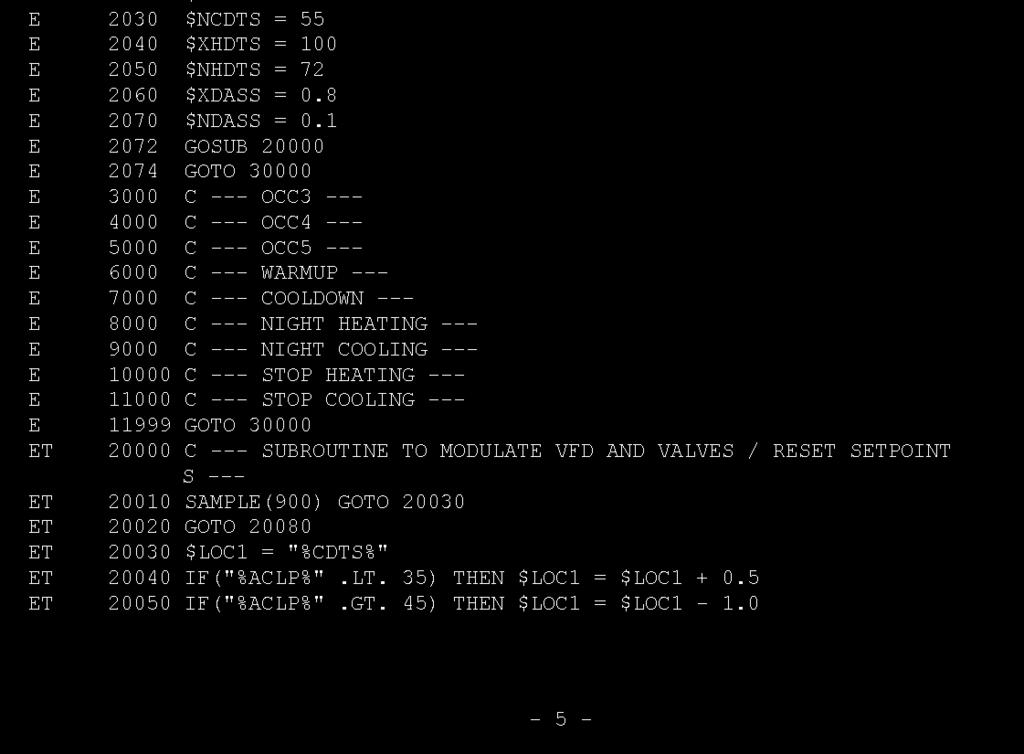
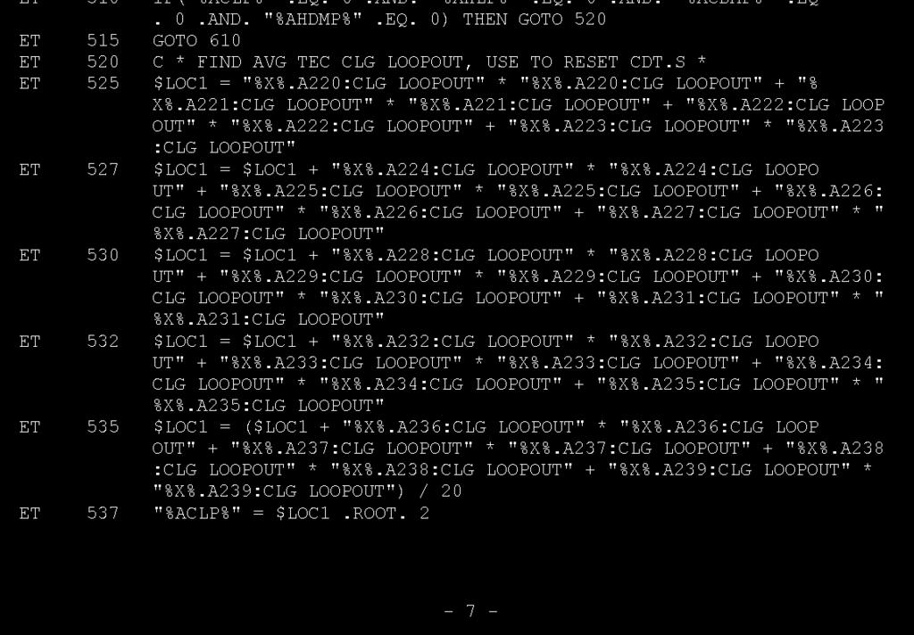
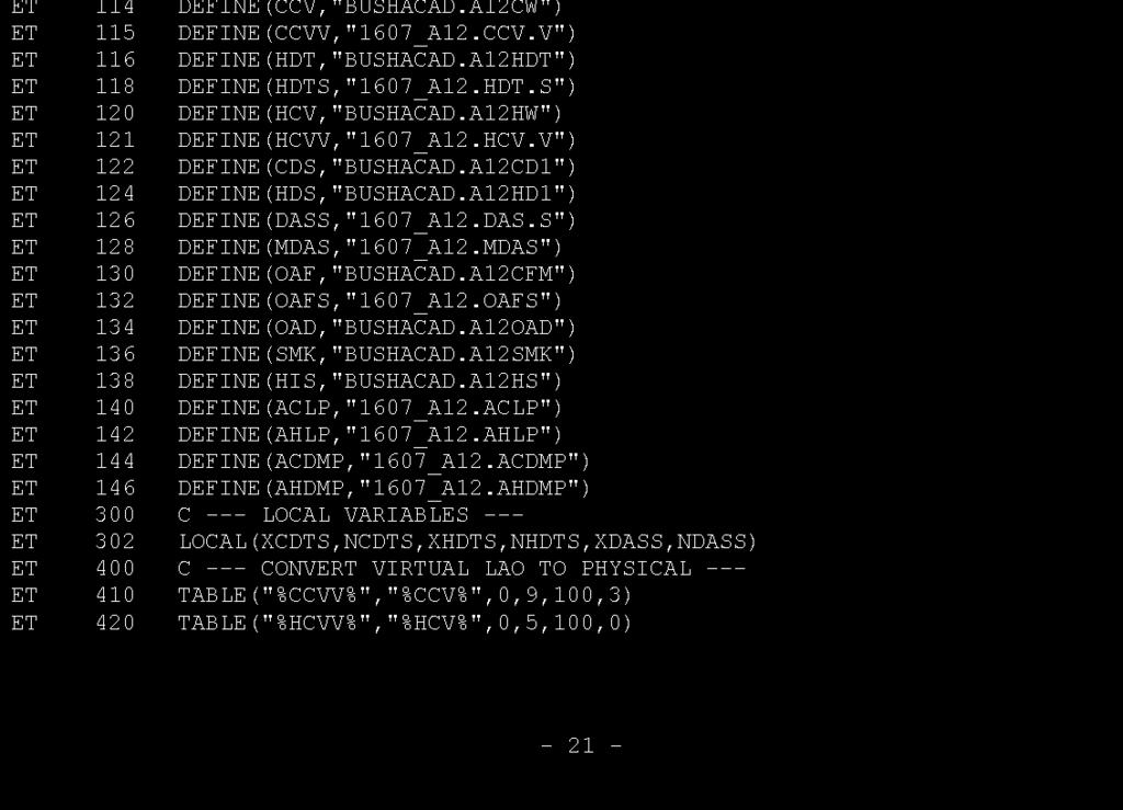
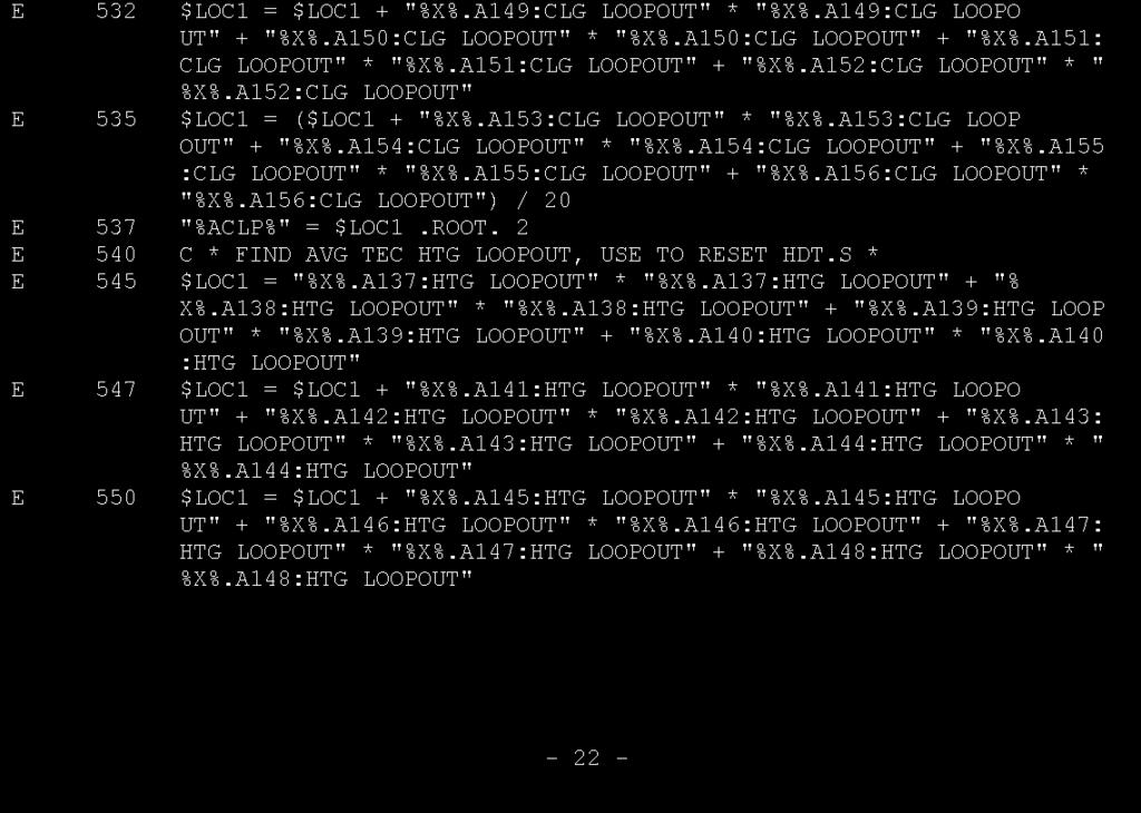
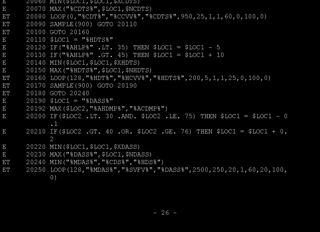
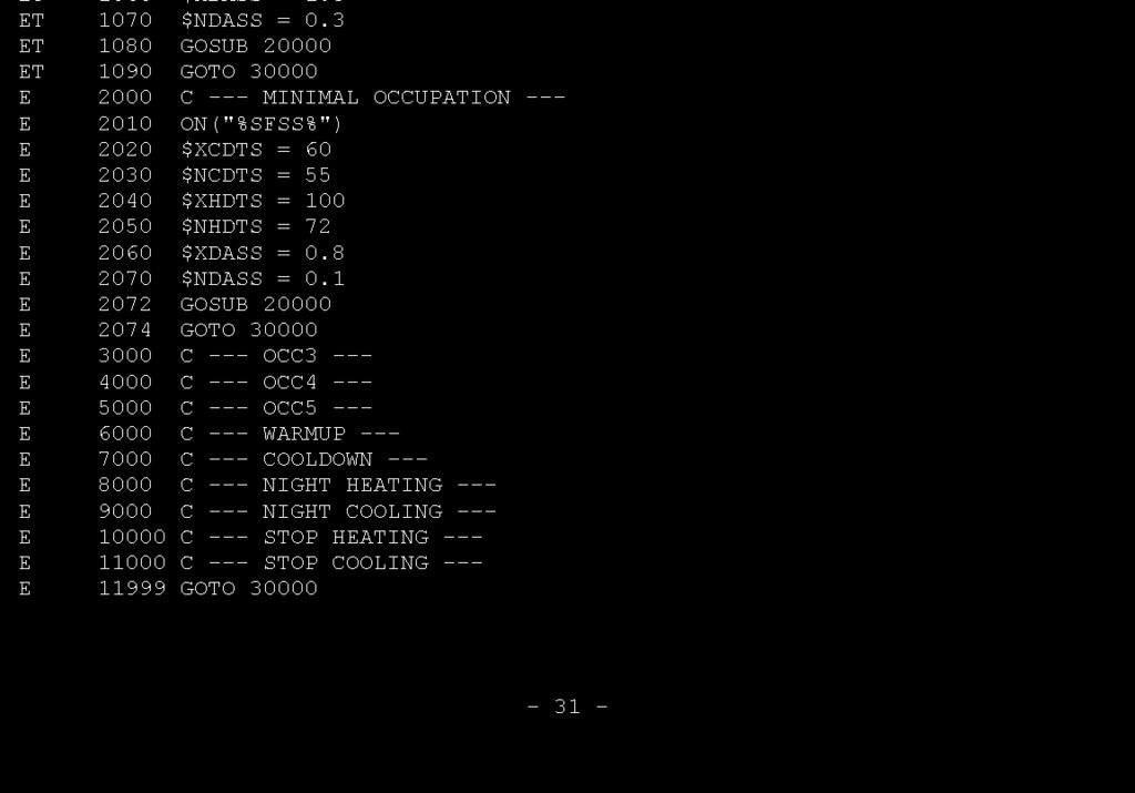
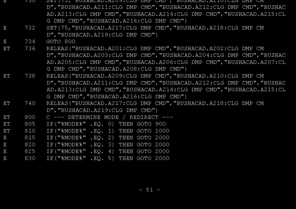
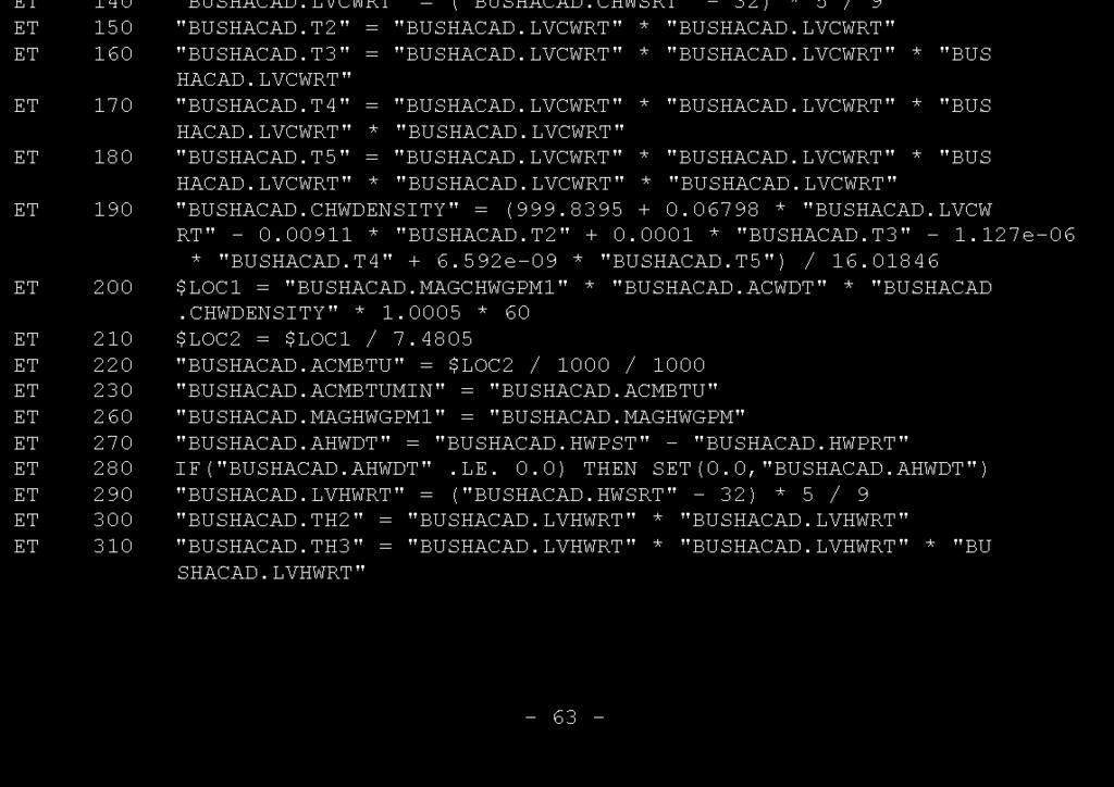
38 APPENDIX D PRE-CC CONTROL PROGRAMMING 31

39 32

40 33

41 34

42 35
43 36
44 37
45 38

46 39

47 40

48 41

49 42

50 43
51 44

52 45
53 46

54 47
55 48
56 49

57 50

58 51

59 52
60 53

61 54

62 55

63 56

64 57
65 58
66 59

67 60

68 61

69 62

70 63
71 64
72 65

73 66

74 67

75 68
76 69

77 70

78 71

79 72
80 73

81 74

82 75

83 76

84 77
85 78

86 79
87 80

88 81

89 82

90 83

91 84

92 85

93 86

94 87
95 88

96 89
97 90

98 91
99 92

100 93

101 94
102 95
103 96

104 97

105 98

106 99

107 100
108 101

109 102

110 103

111 104
Computing Services Center
 Continuous Commissioning Report for the Computing Services Center Building #516 Submitted to: Utilities Energy Office Physical Plant Department Texas A&M University Prepared by: Energy Systems Laboratory
Civil Engineering Building
 Continuous Commissioning Report For the Civil Engineering Building Building 492 Submitted to: Utilities Energy Office Physical Plant Department Texas A&M University Prepared by: Energy Systems Laboratory
Harrington Tower Building
 Continuous Commissioning Report For the Harrington Tower Building Building #435 Submitted to: Utilities Energy Office Physical Plant Department Texas A&M University Prepared by: Energy Systems Laboratory
Physical Plant Complex
 Continuous Commissioning Report For the Physical Plant Complex Building #1156 Submitted to: Utilities Energy Office Physical Plant Department Texas A&M University Prepared by: Energy Systems Laboratory
Continuous Commissioning Report
 ontinuous ommissioning Report for the Price Hobgood Building (Bldg. 1507) Submitted to: Office of Energy Management Physical Plant Department Texas A&M University Prepared by: Energy Systems Laboratory
Retrocommissioning Findings Summary: Building X #1 Priority: Major Comfort/Control Problems
 IMPORTANT NOTICE: This sample document is provided for instructional purposes only. CCC is not rendering advice concerning any commission project or practices. This document is neither approved nor intended
Continuous Commissioning of Commercial Kitchen and Dining Facilities Case Study
 The 7 th International onference for Enhanced Building Operations (IEBO 2007) ontinuous ommissioning of ommercial Kitchen and Dining Facilities ase Study Hui Li, hen Xu, Qiang hen and Song Deng Energy
Submitted to. Texas A&M University-Corpus Christi The Texas A&M University System. Submitted by. Yeqiao Zhu Dan Turner David Claridge
 ESL-TR-99/12-04 Report of Energy Efficiency Study and Metering/Utilities Profile for Electricity Deregulation at the Texas A&M University-Corpus Christi (TAMU-CC) Corpus Christi, Texas Submitted to Texas
Submitted to. Texas A&M University at Galveston The Texas A&M University System. Submitted by. Yeqiao Zhu Dan Turner David Claridge
 ESL-TR-99/12-05 Report of Energy Efficiency Study and Metering/Utilities Profile for Electricity Deregulation at the Texas A&M University at Galveston (TAMU-G) Galveston, Texas Submitted to Texas A&M University
HVAC Controls Upgrades: Requirement Details ( )
") REQUIRED CONTROLS/FEATURES To qualify the upgrade must add or substantially modify 3 or more sequences/system capabilities. Also, all sequences and items listed under the required section are needed in
REQUIRED CONTROLS/FEATURES To qualify the upgrade must add or substantially modify 3 or more sequences/system capabilities. Also, all sequences and items listed under the required section are needed in
AIR HANDLING SYSTEM RETRO-COMMISSIONING TRENDING ANALYSIS
 AIR HANDLING SYSTEM RETRO-COMMISSIONING TRENDING ANALYSIS 1 AIR HANDLING UNIT TRENDS 2 1. The trending charts provided on the following pages prepared as part of a retro-commissioning investigation. The
Continuous Commissioning: A Valuable Partner to Retrofit Projects
 Continuous Commissioning: A Valuable Partner to Retrofit Projects Yeqiao Zhu Aamer Athar Kenneth Banks Ph.D. PE, CEM PE, CEM Energy Systems Laboratory Sempra Energy Solutions Sempra Energy Solutions Charles
Digital Precise Air Control - DPAC
 Digital Precise Air Control - DPAC Mode Enable Sensor Options The temperature of this sensor will determine if the unit is in heating, cooling or vent mode during Occupied operation. The following options
SECTION SEQUENCE OF OPERATIONS FOR HVAC CONTROLS
 SECTION 23 09 93 SEQUENCE OF OPERATIONS FOR HVAC CONTROLS PART 1 - GENERAL 1.1 SUMMARY A. This Section includes control sequences for HVAC systems, subsystems, and equipment. B. See Division 23 Section
Submitted to. Texas A&M University at Commerce The Texas A&M University System. Submitted by. Guanghua Wei Craig Campbell David Claridge Dan Turner
 ESL-TR-99/12-09 Report of Energy Efficiency Study and Metering/Utilities Profile for Electricity Deregulation at the Texas A&M University at Commerce (TAMU-Commerce) Commerce, Texas Submitted to Texas
Impacts of Optimized Cold & Hot Deck Reset Schedules on Dual Duct VAV Systems - Theory and Model Simulation
 Impacts of Optimized Cold & Hot Deck Reset Schedules on Dual Duct VAV Systems - Theory and Model Simulation Mingsheng Liu, Ph.D., P.E. Energy Systems Laboratory Texas A&M University College Station, Texas
Andrea Borowski The Pennsylvania State University University Park, PA November 11, 2002 Consultant: Dr. Bahnfleth Technical Assignment M-3
 Existing System Evaluation Executive Summary The MBNA Career Services Center is a 44,000 square foot, 4-story office type building at Penn State University, University Park Campus. The building is located
UNIVERSITY OF MISSOURI Heating Ventilating and Air-Conditioning (HVAC) 2016 Q1
 2016 Q1") GENERAL: This section provides general standards for overall sizing and design of Heating, Ventilating, and Air Conditioning (HVAC) systems. Other sections contain specific standards for each system per
GENERAL: This section provides general standards for overall sizing and design of Heating, Ventilating, and Air Conditioning (HVAC) systems. Other sections contain specific standards for each system per
REPRODUCTION/DISTRIBUTION IS PROHIBITED. Energy-Savings Strategies for. Rooftop
 Energy-Savings Strategies for Rooftop VAV Systems Occupied set-point temperature Unoccupied set-point temperature Rooftop variable-air-volume (VAV) s are used to provide comfort in a wide range of building
HVAC Controls Upgrades: Requirement Details ( )
") REQUIRED CONTROLS/FEATURES HVAC non CENTRAL PLANT 1) Zone Level Scheduling & Override for all air handlers (supply and exhaust) to match occupied hours by zone DDC or occupancy sensors (OS) allowed. (403.2.4.3,
REQUIRED CONTROLS/FEATURES HVAC non CENTRAL PLANT 1) Zone Level Scheduling & Override for all air handlers (supply and exhaust) to match occupied hours by zone DDC or occupancy sensors (OS) allowed. (403.2.4.3,
Song Deng, P.E. Assistant Director Energy Systems Laboratory Texas A&M University College Station, TX
 Room Temperature ontrol during Season Switchover with Single Duct Variable Air Volume System without Reheat henggang Liu Research Associate Song Deng, P.E. Assistant Director Homer L. Bruner, Jr., EM Mechanical
Design Standard. Thermal Systems (Chilled Water and Hot Water Systems) Detailed specifications follow. CHW AND HHW SUPPLY TEMPERATURE RESET
 Detailed specifications follow. CHW AND HHW SUPPLY TEMPERATURE RESET") Design Standard Detailed specifications follow. PART 1 CHW AND HHW SUPPLY TEMPERATURE RESET 1.1 The Utilities & Energy Services Department (UES) at Texas A&M University is actively identifying and implementing
Design Standard Detailed specifications follow. PART 1 CHW AND HHW SUPPLY TEMPERATURE RESET 1.1 The Utilities & Energy Services Department (UES) at Texas A&M University is actively identifying and implementing
Paul McCown, PE, CEM, LEED AP, CxA Sr. Mechanical Engineer SSRCx, LLC Nashville, TN USA
 Continuous Commissioning of a LEED-EB Gold Certified Office Building Paul McCown, PE, CEM, LEED AP, CxA Sr. Mechanical Engineer SSRCx, LLC Nashville, TN USA KEYWORDS Continuous Commissioning, Retro-Commissioning,
DIGI-VAV APPLICATIONS
 DIGI-VAV DIGI-VAV APPLICATIONS Digi-VAV: An optimization kit for Variable Air Volume Air Handling Units (VAV AHU) that ensures individual zone indoor air quality (IAQ), and minimizes system energy consumption.
Mechanical System Redesign. Dedicated Outdoor Air System. Design Criteria
 Mechanical System Redesign Dedicated Outdoor Air System Design Criteria The outdoor air conditions used were for Philadelphia, Pennsylvania IAP at a 0.4% occurrence. The supply air conditions were developed
SYNOPSIS. Part-Load Control Strategies for Packaged Rooftop Units. In this issue... Bin Hour Profile Charlotte, NC
 VOLUME ONE NUMBER THREE SYNOPSIS A N H V A C N E W S L E T T E R F O R B U I L D I N G O W N E R S A N D M A N A G E R S In this issue... Part-Load Strategies Why they re important.......... 1 What Things
SECTION SEQUENCE OF OPERATIONS FOR HVAC CONTROLS
 PART 1 - GENERAL SECTION 23 09 93 SEQUENCE OF OPERATIONS FOR HVAC CONTROLS 1.1 SUMMARY A. This Section includes control sequences for HVAC systems, subsystems, and other equipment. B. See Division 23 Section
The Creative and Performing Arts High School (CAPA) Pittsburgh, PA 11/11/2002 Andrew Tech Mechanical Option Prof. S. A. Mumma
 Pittsburgh, PA 11/11/2002 Andrew Tech Mechanical Option Prof. S. A. Mumma") Objectives and Requirements For the Creative and Performing Arts High School (CAPA), the main objective of the mechanical design is to provide an energy efficient system that is easily maintainable and
Objectives and Requirements For the Creative and Performing Arts High School (CAPA), the main objective of the mechanical design is to provide an energy efficient system that is easily maintainable and
Continuous Commissioning SM Report. For. Wing 86, Chemistry Complex (Building # 376) Hui Chen Song Deng Homer L. Bruner, Jr., CEM.
 Hui Chen Song Deng Homer L. Bruner, Jr., CEM.") Continuous Commissioning SM Report For Wing 86, Chemistry Complex (Building # 376) By Hui Chen Song Deng Homer L. Bruner, Jr., CEM Contact: Song Deng (979-862-1234) Homer L. Bruner, Jr. (979-862-7185)
Continuous Commissioning SM Report For Wing 86, Chemistry Complex (Building # 376) By Hui Chen Song Deng Homer L. Bruner, Jr., CEM Contact: Song Deng (979-862-1234) Homer L. Bruner, Jr. (979-862-7185)
The Temperature and Relative Humidity Control in Cushing Library
 The Temperature and Relative Humidity Control in Cushing Library Chenggang Liu Research Associate Song Deng Assistant Director Homer L. Bruner, Jr., CEM Mechanical Systems Specialist Utilities Office of
Museum Archive Dehumidification in Hot & Humid Climates
 Museum Archive Dehumidification in Hot & Humid Climates B. K. Browning, PE Principal Engineer KWR Services Austin, Texas ABSTRACT This paper discusses some of the difficulties found with a desiccant dehumidification
The M & V Guided Recommissioning Process. Energy & Water Conservation Program. September 2015 MOO
 The M & V Guided Recommissioning Process MOO Energy & Water Conservation Program September 2015 EWC Agenda MOO EWC Overview Our approach Progress Fault Detection Zone & customer feedback Variance reporting
Verasys System Operation Overview Technical Bulletin
 Contents subject to change. Verasys System Operation Overview Technical Bulletin Code No. LIT-12012370 Issued January 2016 Refer to the QuickLIT Web site for the most up-to-date version of this document.
Improving Control of Dual-Duct Single-Fan Variable Air Volume Systems
 Improving Control of Dual-Duct Single-Fan Variable Air Volume Systems Guanghua Wei, P.E. Joe Martinez Tom Minihan Assistant Research Engineer Research Engineering Associate Graduate Student Tim Brundidge
OSU Alumni Center Phase I Implementation Review. Oregon State University 130 Oak Creek Bldg. Corvallis, Oregon
 OSU Alumni Center Phase I Implementation Review Prepared for Oregon State University 130 Oak Creek Bldg. Corvallis, Oregon 97331 October 31, 2011 Job No. 02.11.00113 Introduction: Glumac was engaged by
Technical Report Three
 Technical Report Three Existing Conditions for Mechanical Systems Contents Executive Summary...2 Building Overview...2 Mechanical Systems Overview...2 Mechanical System...3 Outdoor & Indoor Design Conditions...3
RE: Phase 2 Improvements DATE: July 1, 2016 New Administration Building Wernle Youth & Family Treatment Center 2000 Wernle Road Richmond, Indiana
 ADDENDUM NO. 2 RE: Phase 2 Improvements DATE: July 1, 2016 New Administration Building Wernle Youth & Family Treatment Center 2000 Wernle Road Richmond, Indiana TO: All Bidders Gentlemen: This Addendum
A. Base Bid: 1. Heating Contractor provide: a. Control sequences for HVAC systems, subsystems, and equipment.
 SECTION 23 09 93 - SEQUENCE OF OPERATIONS FOR HVAC CONTROLS PART 1 - GENERAL 1 WORK INCLUDES A. Base Bid: Heating Contractor provide: Control sequences for HVAC systems, subsystems, and equipment. B. Alternate
4. OVERVIEW OF MECHANICAL SYSTEM
 4. OVERVIEW OF MECHANICAL SYSTEM The 87,000 SF SLCC is served by six (6) Trane M-Series Climate Changer Air Handing Units (AHUs). Each unit serves a distinct zone within the facility that is unique in
Auburn University Basketball Arena:
 Auburn University Basketball Arena: How Building Data Analytics Achieved Energy and O&M Savings While Improving Comfort and Sustainability Eric Moore, PE, CEM, Auburn University Hadas Webb, CEM, Cimetrics
DACC Health Sciences Building Air Handler Assessment/Study
 DACC Health Sciences Building Air Handler Assessment/Study NMSU Facilities and Services Department P.O. Box 30001 Las Cruces, NM 88003-8001 June 14, 2016 Final Submittal 1065 S. Main St., Bldg. D, Ste.
IT S HOT UP HERE! A STUDY OF THERMAL COMFORT IN THE LILLIS BUSINESS COMPLEX 4TH FLOOR OFFICES
 IT S HOT UP HERE! A STUDY OF THERMAL COMFORT IN THE LILLIS BUSINESS COMPLEX 4TH FLOOR OFFICES Martha Bohm M.Arch Candidate 2006 University of Oregon Eugene, OR 97403 Will Henderson M.Arch Candidate 2006
B. Use UT Austin specifications and equipment schedule format for HVAC equipment where available.
 PART 1: GENERAL 1.01 General Requirements A. This standard is intended to provide useful information to the Professional Service Provider (PSP) to establish a basis of design. The responsibility of the
BAS Point Trend Data Guidance
 BAS Point Trend Data Guidance Rev. 3, January 2018 Introduction The Building Automation System (BAS also, referred to as a DDC system, or a Direct Digital Control system) at your building has been set-up
CARRIER edesign SUITE NEWS. Modeling 100% OA Constant Volume Air Systems. Volume 6, Issue 1. Page 1 Modeling 100% OA Constant Volume Air Systems
 Volume 6, Issue 1 CARRIER edesign SUITE NEWS Modeling 100% OA Constant Volume Air Systems This article provides an overview of how to model a stand-alone constant air volume (CAV) 100% OA system in HAP.
Dehumidifying with Dedicated Outdoor Air
 Dehumidifying with Dedicated Outdoor Air System Configurations Figure 71. Configurations for dedicated outdoor-air systems A dedicated outdoor-air handler separately filters, cools, dehumidifies, heats,
TEC Controller VAV 0-10V Fan Control with Hot Water Heat, Application Application Note Building Technologies
 TEC Controller VAV 0-10V Fan Control with Hot Water Heat, Application 2236 Application Note 140-1228 Building Technologies Table of Contents Overview... 4 Hardware Inputs... 10 Hardware Outputs... 10
ASHRAE Headquarters Building: GSHP vs. VRF systems
 Jeffrey D. Spitler Oklahoma State University spitler@okstate.edu ASHRAE Headquarters Building: GSHP vs. VRF systems Session C: Technical Learning Objectives Understand how a GSHP system and VRF system
CHAPTER 4. HVAC DELIVERY SYSTEMS
 CHAPTER 4. HVAC DELIVERY SYSTEMS 4.1 Introduction 4.2 Centralized System versus Individual System 4.3 Heat Transfer Fluids 4.4 CAV versus VAV Systems 4.5 Common Systems for Heating and Cooling 4.6 Economizer
CENTRAL KITSAP SCHOOL DISTRICT BOARD PROCEDURE
 MANAGEMENT SUPPORT SERVICES Utilities Management Introduction In support of Central Kitsap School District (CKSD) Utilities Conservation Policy, the following procedure is set forth to establish operating
Improving Performance with a Building Tune-Up. Janice Peterson, P.E. LEED AP Market Manager, Building Operations BetterBricks
 Improving Performance with a Building Tune-Up Janice Peterson, P.E. LEED AP Market Manager, Building Operations BetterBricks How much is too much? Most buildings can cut total energy use by 5-30% while
ASHRAE Region VI CRC Track III: Session 3 Ventilation Energy Recovery. Steven T. Taylor, PE Principal Taylor Engineering
 ASHRAE Region VI CRC Track III: Session 3 Ventilation Energy Recovery Steven T. Taylor, PE Principal Taylor Engineering This program is registered with the AIA/CES for continuing professional education.
University of Iowa Indoor Practice Facility Outside-the-box HVAC OUTLINE AND LEARNING OBJECTIVES:
 University of Iowa Indoor Practice Facility Lincoln Pearce, PE KJWW Engineering David Hahn University of Iowa Chilled Water Plant October 13, 2014 OUTLINE AND LEARNING OBJECTIVES: Project scope Design
7. MECHANICAL SYSTEM DESIGN
 7. MECHANICAL SYSTEM DESIGN The second primary topic of this thesis is to investigate the application of a dedicated outdoor air system (DOAS) to the SLCC. The stated goals for this thesis of improved
SEQUENCE OF OPERATION GUIDELINE. AIR TERMINAL UNITS SINGLE DUCT VARIABLE AIR VOLUME with HOT WATER REHEAT or ELECTRIC HEAT
 SEQUENCE OF OPERATION GUIDELINE AIR TERMINAL UNITS SINGLE DUCT VARIABLE AIR VOLUME with HOT WATER REHEAT or ELECTRIC HEAT Document: VAV-HTG rev1 Revision: 1.0 Rev. Date: July 22, 2011 NOTES: 1. THIS SEQUENCE
SECTION SEQUENCE OF OPERATIONS FOR BUILDING CONTROLS
 PART 1 GENERAL 1.01 SECTION INCLUDES SECTION 23 0993 SEQUENCE OF OPERATIONS FOR BUILDING CONTROLS A. This section defines the manner and method by which controls function. Requirements for each type of
ASHRAE JOURNAL ON REHEAT
 Page: 1 of 7 ASHRAE JOURNAL ON REHEAT Dan Int-Hout Chief Engineer Page: 2 of 7 Overhead Heating: A lost art. March 2007 ASHRAE Journal Article Dan Int-Hout Chief Engineer, Krueger VAV terminals provide
Implementation of the Laboratory Air Handling Unit Systems (LAHU)
") University of Nebraska - Lincoln DigitalCommons@University of Nebraska - Lincoln Architectural Engineering -- Faculty Publications Architectural Engineering 2003 Implementation of the Laboratory Air Handling
University of Nebraska - Lincoln DigitalCommons@University of Nebraska - Lincoln Architectural Engineering -- Faculty Publications Architectural Engineering 2003 Implementation of the Laboratory Air Handling
EarthWise System Seminar
 EarthWise System Seminar Tim Gasper, P.E. Solutions Engineer Brady-Trane Services, Inc. EarthWise Systems? Energy Efficiency Emissions Buildings use 39% of the Primary Energy Consumed in the United States
MID MICHIGAN COMMUNITY COLLEGE HARRISON CAMPUS Harrison, Michigan 2015 MASTER PLAN
 MID MICHIGAN COMMUNITY COLLEGE HARRISON CAMPUS Harrison, Michigan 2015 MASTER PLAN September 30, 2015 PBA Project No. 2015.0140.00 PETER BASSO ASSOCIATES INC. CONSULTING ENGINEERS 5145 LIVERNOIS ROAD,
Technical Report #3 Mechanical Systems Existing Conditions Evaluation
 Mechanical Option Technical Report #3 Technical Report #3 Mechanical Systems Existing Conditions Evaluation Instructor: Dr. Bahnfleth 11.15.04 Building Sponsor: CCG Facilities Integration Table of Contents
TECHNICAL REPORT 3 Mechanical Systems and Existing Conditions Northfield Mental Healthcare Center Northfield, Ohio
 Technical Report 3 Northfield Mental Healthcare Center Dr. Stephen Treado Ji Won Park Mechanical Option Fall 2012 TECHNICAL REPORT 3 Mechanical Systems and Existing Conditions Northfield Mental Healthcare
INTRODUCTION TO: ASHRAE STANDARD 90.1, HVAC System Requirements for Reducing Energy Consumption in Commercial Buildings
 INTRODUCTION TO: ASHRAE STANDARD 90.1, 2013 HVAC System Requirements for Reducing Energy Consumption in Commercial Buildings Rocky Mountain ASHRAE Technical Conference, April 29, 2016 SEAN BEILMAN, P.E.,
Description of All Alternatives Considered-
 Description of All Alternatives Considered- Energy efficiency is an area where the Tubman design can be improved. The design heating load is 1807.8 MBH and the design cooling load is 1702.2 MBH or 142
UNIFIED FACILITIES GUIDE SPECIFICATIONS
 USACE / NAVFAC / AFCEC / NASA UFGS-23 09 93 (November 2015) ----------------------------- Preparing Activity: USACE Superseding UFGS-23 09 23 (May 2011) UNIFIED FACILITIES GUIDE SPECIFICATIONS References
SECTION SEQUENCE OF OPERATION FOR HVAC CONTROLS PART 1 GENERAL
 SECTION 15910 SEQUENCE OF OPERATION FOR HVAC CONTROLS PART 1 GENERAL 1.1 RELATED DOCUMENTS A. Drawings and general provisions of the Contract, including General and Supplementary Conditions and other Division
Case Study: Furman University Charles H. Townes Center for Science. Michael K. Mantai, PE, CCP President System WorCx
 Case Study: Furman University Charles H. Townes Center for Science Michael K. Mantai, PE, CCP President System WorCx AIA Quality Assurance Learning Objectives 1. Case study example of Chilled Beam technology
HAP e-help. Modeling Induction Beams in HAP v4.8 QB TIP 001
 This HAP e-help provides a high-level overview of induction beams, how they work and how to model them in HAP 4.8 (and later versions). The first half of the article explains how induction beams work.
1080 Marina Village Parkway, Suite 501 Alameda, CA (510) Fax (510) HVAC DESIGN INTENT
 Fax (510) HVAC DESIGN INTENT") Taylor Engineering 1080 Marina Village Parkway, Suite 501 Alameda, CA 94501-1142 (510) 749-9135 Fax (510) 749-9136 LLC HVAC DESIGN INTENT PART 1 - GENERAL 1.1 Overview A. The project consists of a 3-story
Taylor Engineering 1080 Marina Village Parkway, Suite 501 Alameda, CA 94501-1142 (510) 749-9135 Fax (510) 749-9136 LLC HVAC DESIGN INTENT PART 1 - GENERAL 1.1 Overview A. The project consists of a 3-story
Selected Laboratory Energy Efficiency Measures
 Selected Laboratory Energy Efficiency Measures These are some of the most effective energy efficiency measures for laboratories 1. Reduce (optimize) air changes per hour in lab space 2. Design to the proper
b.) Technical Information:
 Technical Information:") Section VI- Strategies a.) Summary: It is important for new construction designers to consider the heating, ventilation, and air conditioning needs within a building. There are many different systems,
Section VI- Strategies a.) Summary: It is important for new construction designers to consider the heating, ventilation, and air conditioning needs within a building. There are many different systems,
DEHITMIDlFICATION WITHOUT REHEAT USING FACE AND BYPASS DAMPERS
 DEHITMIDlFICATION WITHOUT REHEAT USING FACE AND BYPASS DAMPERS Dale T. Warila Member Group Technical Staff Texas Instruments Dallas, Texas ABSTRACT: Installations with chill water cooling, needing constant
H3/V3 Series Horizontal and Vertical Indoor Air Handling Units. Engineering Catalog
 H3/V3 Series Horizontal and Vertical Indoor Air Handling Units Engineering Catalog Table of Contents AAON H3/V3 Series Features and Options Introduction... 6 H3/V3 Base Model Description... 7 Unit Size...
INTRODUCTION HVAC BASICS AND HVAC SYSTEM EFFICIENCY IMPROVEMENT SECTION O 4/19/2012
 HVAC BASICS AND HVAC SYSTEM EFFICIENCY IMPROVEMENT SECTION O INTRODUCTION HVAC systems or Heating, Ventilating and Air-Conditioning systems control the environment for people and equipment in our facilities.
Engineering Guide VAV Diffusers. Please refer to the Price Engineer s HVAC Handbook for more information on VAV Diffusers.
 VAV Diffusers lease refer to the rice Engineer s HVAC Handbook for more information on VAV Diffusers. Diffuser Types Ceiling Diffusers Conventional air distribution systems typically group several rooms
FLORIDA A&M UNIVERSITY PERFORMANCE CONTRACT SCOPE OF WORK
 FLORIDA A&M UNIVERSITY PERFORMANCE CONTRACT SCOPE OF WORK ENERGY CONSERVATION MEASURE 1 Partial Steam System Decentralization SIEMENS will Furnish and Install condensing hot water boilers with associated
FACILITY ACTION PLAN
 FACILITY Mary Baker Russell Music Center CURRENT ENERGY USE INDEX (EUI) 293 kbtu/sq Ft 26.83 kwh/sq Ft FACILITY LIASON(S) David Robbins Chair of the Department of Music FACILITY ACTION PLAN TARGET EUI
DX-9100 Applications from Engineering Services
 System 9100 Technical Manual 636.4 Application Examples Section Technical Bulletin Issue Date 0896 DX-9100 Applications from Engineering Services Introduction Page 3 Overview 3 Air Handling Unit Applications
Technical Assignment 3
 0 David H. Koch Institute for Integrative Cancer Research Senior Capstone Mechanical Option Technical Assignment 3 Mechanical Systems and Existing Conditions Report David H. Koch Institute for Integrative
IAQ: Re-tuning Commercial Buildings
 IAQ: Re-tuning Commercial Buildings A low-cost path to improved air quality and energy efficiency. B y S c o t t G o r d o n, C M All images courtesy of Johnson Controls Service. 10 RSES Journal FEBRUARY
DADANCO Technical Paper
 DADANCO Technical Paper 260 North Elm Street Westfield, MA 01085 Phone: (413) 564-5657 Fax: (413) 568-2969 March 2013 CLASSROOM SOLUTION USING ACTIVE CHILLED BEAMS (Note: This technical paper assumes the
Benefits Offered by Passive Dehumidification Wheel Speed Control
 Benefits Offered by Passive Dehumidification Wheel Speed Control White paper By John Fischer Benefits Offered by Passive Dehumidification Wheel Speed Control The most significant advantage of the Pinnacle
Job Name Control Systems Description Date
 Job Name Control Systems Description Date Project Overview The project is a describe the building and its major HVAC systems (e.g. three-story office building, served by a rooftop unit VAV system ). In
Matt Cooper, PE, BEMP, HBDP, Group 14 Engineering Ken Urbanek, PE, HBDP MKK Consulting Engineers, Inc.
 M&V Real Results of High Performance Design Matt Cooper, PE, BEMP, HBDP, Group 14 Engineering Ken Urbanek, PE, HBDP MKK Consulting Engineers, Inc. Overview Measurement & Verification (M&V) Plan for New
Energy Management and Controls
 As with the Chapter Review Tests and the Final Exam, the tests your understanding of the materials underlying the learning objectives. After you ve reviewed your answers to the Chapter Review Tests, try
Designing Energy Efficient Outdoor Air Systems
 Designing Energy Efficient Outdoor Air Systems Joseph Thorndal Applied Products Sales Manager Greenheck, Schofield, Wisconsin 1 Joseph Thorndal BS Industrial Engineering North Dakota State University Work
TAP v2.10 Version Date: 6/12/13. Document Microprocessor Controller for Tempered Air Products
 Document 475595 Microprocessor Controller for Tempered Air Products Reference Guide for the Microprocessor Controller Please read and save these instructions. Read carefully before attempting to operate
November 11, City of Sparks 215 S. 21 st St. Sparks, NV
 November 11, 2014 City of Sparks 215 S. 21 st St. Sparks, NV 89432-0857 Attn: Brian Cason Re: Sparks City Hall HVAC Upgrade Project-Alerton Direct Digital HVAC Control System to Match Existing City of
AIR-CONDITIONING SYSTEMS AND APPLICATIONS. Abdullah Nuhait Ph D. King Saud University
 AIR-CONDITIONING SYSTEMS AND APPLICATIONS Abdullah Nuhait Ph D. King Saud University AIR-CONDITIONING SYSTEMS Earliest air conditioning system used only for heating (winter) Provided heated air for comfort
HONORABLE MENTION: COMMERCIAL BUILDINGS, EXISTING
 ASHRAE s BEST This article was published in ASHRAE Journal, November 2010. Copyright 2010 American Society of Heating, Refrigerating and -Conditioning Engineers, Inc. Reprinted here by permission from
Effect Of Setup Thermostat Schedule On Heat Pump Water Heater Energy Consumption, Coefficient Of Performance And Peak Load
 Effect Of Setup Thermostat Schedule On Heat Pump Water Heater Energy Consumption, Coefficient Of Performance And Peak Load Philip Boudreaux, Roderick Jackson, Jeffrey Munk and Anthony Gehl, Oak Ridge National
APPLICATION GUIDE BEAMS
 BEAMS There is an increasing need for energy efficient air conditioning systems as energy codes become more stringent. Chilled beam systems are one such alternate to traditional all air conditioning systems.
Guide Spec Summary. Option List. Date: 05/21/2001. EarthWise VAV Terminal Units Full Spec. Prepared by: Phone Number: Prepared for:
 Date: 05/21/2001 Time: 02:57:44 PM Job Name: EarthWise VAV Terminal Units Full Spec Location: AnyTown, Earth Prepared by: Phone Number: Prepared for: Guide Spec Summary Option List SINGLE & DUAL DUCT UNIT
Best Practices for Condensing Boilers
 ASHRAE www.ashrae.org. Used with permission from ASHRAE Journal at www.cleaverbrooks.com. This article may not be copied nor distributed in either paper or digital form without ASHRAE s permission. For
Senior Thesis Centre Community Hospital East Wing Addition - Proposal Keith Beidel Mechanical Option 12/05/02 1
 Table of Contents Page Number(s) Executive Summary 2 Project Background 3 Proposed Depth Alternatives 4 Proposed Depth Redesign 5-7 Justification of Proposed Depth Redesign 8 Proposed Breath Redesign 9
York 25-Ton VAV Rooftop Unit
 HVAC PRO for Windows User s Manual 637.5 OEM Section Technical Bulletin Issue Date 0996 York 25-Ton VAV Rooftop Unit Introduction Page 3 Overview *3 Configuration 5 Sequence of Operation 7 Modes of Operation
Energy Savings Potential of Passive Chilled Beam System as a Retrofit Option for Commercial Buildings in Different Climates
 Purdue University Purdue e-pubs International High Performance Buildings Conference School of Mechanical Engineering 2014 Energy Savings Potential of Passive Chilled Beam System as a Retrofit Option for
PINNACLE SERIES DEDICATED OUTDOOR AIR SYSTEM ENERGY EFFICIENT DEHUMIDIFICATION
 ENERGY EFFICIENT DEHUMIDIFICATION PINNACLE SERIES DEDICATED OUTDOOR AIR SYSTEM Provides a very high degree of latent cooling using only a minimal amount of conventional cooling input Substantial energy
Zoned Rooftop Systems. Light commercial packaged rooftop systems from Trane
 Zoned Rooftop Systems Light commercial packaged rooftop systems from Trane Trane Zoned Rooftop Systems Components of Trane Zoned Rooftop Systems p. 3 Zoned Rooftop System Configurations p. 4 Systems comparison
Technical Development Program. COMMERCIAL HVAC PACKAGED EQUIPMENT Split Systems PRESENTED BY: Ray Chow Sigler
 Technical Development Program COMMERCIAL HVAC PACKAGED EQUIPMENT Split Systems PRESENTED BY: Ray Chow Sigler Menu Section 1 Section 2 Section 3 Section 4 Section 5 Section 6 Section 7 Introduction System