User s Manual AZURE COUNTER FLOW HEAT RECOVERY VENTILATION
|
|
|
- Gerald Fowler
- 5 years ago
- Views:
Transcription
1 User s Manual AZURE COUNTER FLOW HEAT RECOVERY VENTILATION
2 CONTENTS 1.0 Important information Warning and safety instructions Warranty claims Exclusion of liability Regulations Guidelines Receipt Storage Transport Intended use Performance data Guideline series VDI Heat systems Technical data Disposal Disassembly and re-assembly... 7 CHAPTER 2 INSTALLATION 2.0 Assembly Ceiling installation Condensation outlet Flange connection / adapter pieces Air ducting, Ventilation circuit Electrical Connection...10 CHAPTER 3 FUNCTIONAL DESCRIPTION 3.0 Unit Description Fuctional Diagram...12 CHAPTER 4 DIMENSIONS - PERFORMANCE CURVE 4.0 Dimensions Performance curves...15 CHAPTER 5 SERVICE AND MAINTENANCE 5.0 Service and maintenance Removing/cleaning cross counter flow heat exchanger Filter change Service and maintenance of fans Service and maintenance of pre-electrical heater Pre-electrical heater reset function Condensate tray Terminal box with isolator/main switch...25 CHAPTER 6 Installations, service and maintenance of accessories 6.1 Accessory list Installation of water after heater Installation of electrical after heater Installation of condensate pump...31 CHAPTER 7 WIRING DIAGRAM OVERVIEW 7.1 AZURE 500 wiring diagram AZURE 700 wiring diagram AZURE 1400 wiring diagram AZURE 2200 wiring diagram AZURE 3200 wiring diagram...44 CHAPTER 8 SPARE PART LIST
3 CHAPTER 1 GENERAL INSTALLATION AND OPERATING INSTRIUCTIONS 1.0 Important information To ensure safety and correct operation please read and observe the following instructions carefully before proceeding. Important information is specified in the maintenance section on filter changes and necessary cleaning and maintenance activities. The user usually carries out maintenance work. The chapter Installation with important installation tips and basic unit adjustments is intended for the specialised installer. The electrical connection must be fully isolated from the supply up to the final assembly! This appliance is not intended for use by persons (including children) with reduced physical, sensory or mental capabilities, or lack of experience and knowledge, unless they have been given supervision or instruction concerning use of the appliance by a person responsible for their safety. Children should be supervised to ensure that they do not play with the appliance. The planning office provides the planning documents necessary for system calculations. Additional information can be requested ex works. Keep the installation and operating instructions as a reference at the device. After the final assembly, the document must be handed out to the operator (tenant/owner). 1.1 Warning and safety instructions The adjacent symbol is a safety-relevant prominent warning symbol. All safety regulations and/or symbols must be absolutely adhered to, so that any dangerous situation is avoided. 1.2 Warranty claims Exclusion of liability If the preceding instructions are not observed, all warranty claims and accommodation treatment are excluded. This also applies to any liability claims extended to the manufacturer. The use of accessories not offered or recommended by AERA is not permitted. Potential damages are not covered by warranty. 1.3 Regulations Guidelines If the product is installed correctly and used to its intended purpose, it conforms to all applicable CE standards at its date of manufacture. The AERA AZURE ventilation units in this series are compliant with Eco-Design A E R A A I R I N N O V A T I O N 3
4 CHAPTER Receipt The delivery contains one of the following unit types: Unit AZURE 500 AZURE 700 AZURE 1400 AZURE 2200 AZURE 3200 The scope of delivery also includes: 4x Vibration pad Please check delivery immediately on receipt for accuracy and damage. If damaged, please notify carrier immediately. In case of delayed notification, any possible claim may be void. 1.5 Storage When storing for a prolonged time the following steps are to be taken to avoid damaging influences: Protection by dry, air- dustproof packing. The storage place must be water protected, vibration-free and free of temperature variations. (Ambient temperature limit, min/max, 0 C/ +40 C) Damages due to improper transportation, storage or putting into operation are not covered by warranty. 1.6 Transport The unit is packed ex works in a timber frame so that it is protected against normal transport strain. Carry out the shipping carefully. It is recommended to leave the unit in the original packaging until installation to avoid possible damages and soiling. The transport must be carried out by trained and experienced personnel and the necessary safety precautions should be taken to prevent overturning and slipping of the device. During transport of the devices it should be ensured that the weight is evenly distributed over the four corners. Danger due to overhead loads risk of grave injuries or death! - Never stand beneath suspended loads, since there is always a risk that the lifting gear, tackle, ropes or slings are faulty or damaged. - Make sure that equipment is firmly seated before lifting it. Risk of injury! Watch out for nails when disassembling the timber frame! Warning! Risk of personal injury and equipment damage! 4
5 CHAPTER 1 Due to a high center of gravity, some equipment can tend to tip over and cause damage to persons and property. - When transporting the unit, carefully observe its behavior and do not get near any possible hazardous areas. 1.7 Intended use AZURE devices are designed in 5 different models to correspond the need of up to 3200 m3/ h air flow. There is a epm1 55% class filter on the fresh air side and a epm10 50% class filter on the exhaust side as standard. The units are produced according to European Union energy criteria. AZURE devices are designed with high energy efficient, low sound pressure and low power consumption plug fans. Plug fans with EC motors can be driven with 3 fixed speeds or steplessly with the help of an air quality sensor thanks to build in smart control system. The AZURE units are equipped with counter flow heat exchangers, in which the heat of the extracted air is recovered and transferred through the plates to the incoming fresh external air, so both air flows remain separated. Through this procedure more than 80 % of the extract air heat is transferred to the external air. The supply air is led by the duct system to the primary (supply air needing) areas. The used air is extracted from the secondary areas (like e.g. social rooms, toilets, showers etc.). It flows back through the ducting to the ventilation unit, transfers the heat and is discharged by the exhaust air duct to the atmosphere. The heat recovery efficiency depends on several factors, which include, among other things, air humidity and the temperature variation of outside air and exhaust air. The fan performance can be adjusted by the controller in scope of delivery. Various sensors e.g. CO2 or humidity sensors (accessory) are available on request, with which automatic fan control is possible. Permissible operating air temperature and humidity is 0/40 C and 95% RH for AZURE units. Electrical pre-heater (accessory) are used for preventing the cross counter flow heat exchanger from freezing at extremely cold outdoor temperatures. The summer bypass is the optimal solution for leading the colder outside air into the building in the warmer seasons. The installed filter optimally filters the air, which guarantees a hygienic unit and simultaneously ensures the service life of the compact unit. Electrical after heater (accessory) used in AZURE devices. The electrical after heater is controlled by the desired supply air temperature. The temperature is chosen by the user. A E R A A I R I N N O V A T I O N 5
6 CHAPTER 1 Water after heater (accessory) are used for increasing the supply air temperature and for bringing the supply air to the desired temperature. Hot water coils can be driven by proportional control via 2 or 3-way valves. Frost protection mechanism is available as standard to prevent the temperature of the supply water from reaching freezing conditions in extreme cold climates. Water cooling coils and DX coils (accessory- not included in scope of delivery) are used for such purposes as lowering the blowing temperature and dehumidifying the air in the units. It can be driven either proportionally or by on / off method. 1.8 Performance data Mechanical connections must be made correctly in order to obtain maximum efficiency from the device. The device s thermal efficiency, sound level and electrical performance may vary depending on the ambient conditions the device is operating. These conditions may affect the measurement result on site and vary from the catalogue data. 1.9 Guideline series VDI 6022 The AERA AZURE ventilation units in this series are produced compliant with VDI The guidelines range from operating regulations and material requirements through to construction regulations, which ensure high air quality. It must be ensured that only original AERA accessories are used for operation compliant with VDI Heat systems The simultaneous use of controlled ventilation (AZURE units) and heat systems which depend on room air (tile oven, gas stove etc.) requires compliance with all applicable regulations. The use of heat systems which depend on room air are only permitted in stateof-the-art dense apartments with separate combustion air supply; only then are AZURE and heat systems decoupled from each other and operable meeting the demands. The relevant applicable regulations on the combined use of heat systems, domestic ventilation and extractor hoods (Federal Association of Chimney Sweeps (ZIV)) must be observed! 6
7 CHAPTER Technical Data MODEL AZURE Air flow (m 3 /h) Rated current ventilation (A) 3 3 4,3 6,8 11,3 Rated current pre-heating (A) 7 3,3 6,5 10,2 15,2 Rated current after-heating (A) 7 3,3 6,5 10,2 15,2 Max. total rated current (A) 10,5 4,9 8,7 13,6 20,8 Power consumption ventilation(kw) 8,2x8,2x7,3 15,2x15,2x13,6 23,8x23,8x21 36x36x30,9 Power consumption pre-heating (kw) 1,6 2,3 4,5 7,05 10,5 Power consumption after-heating (kw) 1,6 2,3 4,5 7,05 10,5 Max. power consumption (kw) 3,7 5,1 10,1 15,8 23,7 Voltage/Frequency 1~230V 50Hz 3~400V 50Hz 3~400V 50Hz 3~400V 50Hz 3~400V 50Hz Filter class (extract / outdoor air) epm10 50% -M5 / epm1 55% - F7 epm10 50% -M5 / epm1 55% - F7 epm10 50% -M5 / epm1 55% - F7 epm10 50% -M5 / epm1 55% - F7 epm10 50% -M5 / epm1 55% - F7 Weight (kg) Sound pressure (db) Standby losses < 1W < 1W < 1W < 1W < 1W IP Class IP20 IP20 IP20 IP20 IP20 Wiring diagram Fig Fig Fig Fig Fig A E R A A I R I N N O V A T I O N 7
8 CHAPTER 1 EcoDesign Points AZURE Declared typology Bidirectional Bidirectional Bidirectional Bidirectional Bidirectional Type of drive Variable Variable Variable Variable Variable Type of HRS Recuperative Recuperative Recuperative Recuperative Recuperative Nominal NRVU flow rate [ m3/h ] / Pressure drop [Pa] 500 / / / / / 250 Max. ecodesign flow rate [ m3/h ] / Pressure drop [Pa] 615 / / / / / 392 Thermal efficiency of heat recovery at nominal airflow [ % ] 82,4 82,4 81,1 82,3 83,1 Thermal efficiency of heat recovery at max. ecodesign point [ % ] 81,1 81,4 80,6 81,8 83 Static efficiency of fans at max. ecodesign point [ % ] 44,3 51,1 57,6 57,6 53,2 Face velocity at nominal airflow [ m/s ] 1,4 1,6 2,2 2,13 2,21 Internal pressure drop at max. ecodesign point [ Pa ] Internal total pressure drop at max. ecodesign point [ Pa ] SFP int at max. ecodesign point [ W/(m3/s) ] SFP int_limit at max. ecodesign point [ W/(m3/s) ] Declared maximum external leakage [ % ] Declared maximum internal leakage [ % ] Description of visual filter warning Pressure controled Pressure controled Pressure controled Pressure controled Pressure controled Casing sound power level (Lwa) [ db(a) ] ErP Compliance Disassembly and re-assembly Mechanical connections must be made correctly in order to obtain maximum efficiency from the device. The device s thermal efficiency, sound level and electrical performance may vary depending on the ambient conditions the device is operating. These conditions may affect the measurement result on site and vary from the catalogue data. WARNING Before starting any disassembly or re-assembly operation, please ensure that the product is isolated from its mains electrical supply, in order to ensure that fans cannot be run. As disassembly and re-assembly are not part of routine maintenance, these should be carried out by qualified personnel. 8
9 CHAPTER 1 Ensure the unit is voltage-free and isolated, earth and short circuit the unit, cover or shield off neighbouring live components. Ensure that the hydraulic circuit is switched off. Close all hydraulic shut-off valves. Isolate all connections and ensure leak-free condition regarding oil, refrigerant As the coil piping diameter is small, waste water can remain in the unit following normal evacuation. For safety reasons, use compressed air to blow through the system in order to remove all remaining water. WARNING Risk of personal injury and equipment damage! Due to a high center of gravity, some equipment can tend to tip over and cause damage to persons and property. When transporting the unit, carefully observe its behaviour and do not get near any possible hazardous areas Disposal WARNING Before starting any operation, please ensure that the product is isolated from its mains electrical supply, in order to ensure that fans cannot be run. Dspose of all components and filters and disused operating materials (e.g. oil, refrigerants) in an environmentally-friendly manner in accordance with the local codes, practices and environmental regulations. An authorized appointed contractor specializing in waste processing must dispose of the unit or its individual components. This appointed contractor must ensure that: the components are separated according to material types the used operating materials are sorted and separated according to their respective properties. A E R A A I R I N N O V A T I O N 9
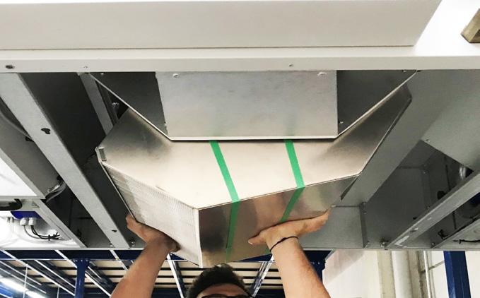
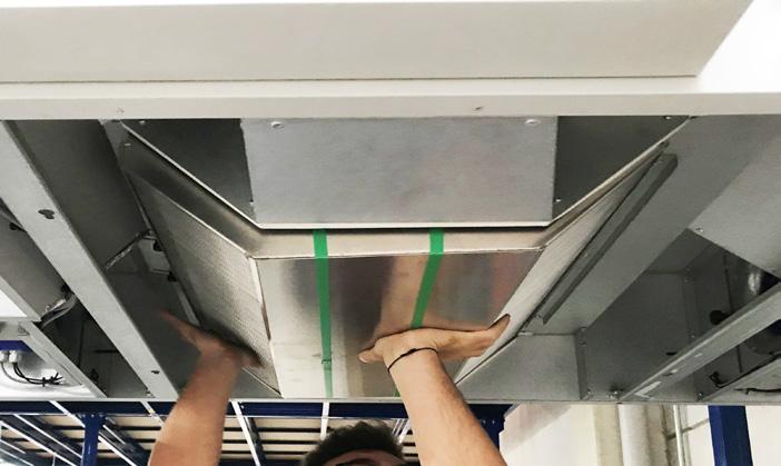
10 CHAPTER 2 INSTALLATION 2.0 Assembly AZURE compact devices are suitable for ceiling mounting thanks to the hanging apparatuses found on. Due to noise level which change according to working conditions, it is recommended to install the AZURE units in the different rooms. Ensure that there is a waste water connection in the installation area. Please consider the information on the condensation outlet! Assembly should take place in such a way to enable preferably short ventilation ducts and their trouble-free connection to the unit. Tight bends in the channel will cause high pressure drops. Important notes: 1. The ventilation ducts must not become kinked. 2. The connections to the connection valves must be firm and tight. 3. Flange connections must be leakproof and firm 4. The terminal box is connected to the side of the casing and maintenance and service space should be left for the doing any work on the device. 5. The assembly of the AZURE compact unit must only take place in rooms that are free of frost, as there is a danger of freezing. The room temperature must not fall below +5 C 6. In order to prevent sound transmission, appropriate acoustic decoupling must be provided on site depending on the building material. 2.1 Ceiling installation DANGER TO LIFE! Before installing the compact unit, it must be ensured that the ceiling and/or the fixing components used can withstand the heavy weight and vibration of the AZURE unit. Unsuitable mounting material can lead to the unit falling uncontrollably from the ceiling. There is danger to life due to the heavy weight! Furthermore, it can also lead to a large amount of property damage! Depending on the mounting, a further safeguard must be implemented to safeguard the AZURE compact unit from falling uncontrollably! Four mounting brackets (with vibration pads (standard unit delivery)) (Fig.1) are mounted to the unit for ceiling installation. Installation to the ceiling takes place e.g. with hanger bolts or suitable mounting accessories. 10
 A is the minimum distance for opening service cover.")
11 CHAPTER 2 Fig.1 When installing to ceiling, it is recommended that the heat exchanger is removed from the unit to reduce the installation weight when lifting. Assembly area Observe the following criteria during installation to ensure that the device service is comfortable. (Fig. 2) A is the minimum distance for opening service cover. C is the minimum distance for servicing the terminal box. ATTENTION In assemblies where the minimum distance A is not available, the service doors can be removed from the hinges. C MODEL A B C D Dimensions (mm) AZURE AZURE AZURE B AZURE AZURE A E R A A I R I N N O V A T I O N 11
12 CHAPTER Condensation outlet The humidity of exhaust air condenses to water during the heating period. A lot of condensate can build up in new buildings with large numbers of people. The condensate water collected in the condensate tub made of stainless steel. (The condensate water can discharge via a ball siphon (accessory). ATTENTION The drainage pipe route must not rise above the siphon! Condensate water can be easily removed from the condensate tube. If the water is to be raised to a certain height, a suitable pump should be used. (7.6 Condensate pump) The condensation outlet must be made frost-proof with proper insulation. 2.3 Flange connection / adapter pieces AZURE flange connection diameters are shown below (Fig. 3) ATTENTION Fixing sheet metal must be used for flange connection in AZURE (included in scope of flange delivery.) Fig.3 12
13 CHAPTER 2 Unit type Dimensions (mm) A B C D n E F AZURE AZURE AZURE AZURE AZURE n : number of drill hole (horizontal) (Except corner holes) Hole/Bolt dimension: M8X20 Adapter pieces for ducts are available from AERA. NOTE The piping must be firmly and tightly connected to the connection valves. Refer to the illustrations for the arrangement of ventilation ducting. 2.4 Air ducting, Ventilation circuit When designing the ductwork, use the shortest possible runs. Airtight connections and changeovers must be ensured for the best possible heat recovery. To avoid pressure losses, dirt build-up and noise, use smooth ducts (plastic or rigid ducting). Exhaust and outside air pipes are to be insulated in an appropriate way to reduce condensation. The minimum insulating thicknesses pursuant to DIN EN , are to be observed. If supply and extract air ductwork runs through unheated rooms, insulation must be provided to reduce heat losses. A filter (accessory) is to be connected for the extraction of polluted extract air. The installation of extractor hoods to the system is not permitted (reasons: dirt, fire danger, hygiene). All fire and building regulations must be observed! WARNING 2.5 Electrical connection The unit must be fully isolated from the mains power supply before any maintenance and installation work or before opening the enclosure! The electrical connection must only be carried out by an authorised qualified electrician in accordance with the following wiring diagrams. The electrical connection must be fully isolated from the mains power supply until the assembly is complete! A E R A A I R I N N O V A T I O N 13
14 CHAPTER 2 The unit is equipped with a main switch and an isolator which can be secured against unauthorized switching with a U-lock. The relevant standards, safety regulations (e.g. DIN VDE 0100) and the technical connection conditions of the local electricity supply companies must be observed. An all-pole mains switch / isolator, with a contact opening of at least 3 mm (VDE 0700 T / EN ) must be provided. The main switch and/or isolator can be secured against unauthorized switching with a U-lock. The surface-mounted controller with touchscreen is connected to the unit by means of a 5 m connecting cable (also available in 10 or 20 m length). The electrical connection of the AZURE takes place directly in the terminal box. If any electronic accessory is added the unit, the electrical connections must be made in the terminal box. These circuit breakers recommended from the manufacturer for the AZURE units below. AZURE Phase Type C C C C C Circuit Breaker (A) For the leakage current protection manufacturer recommended 30mA residual current device. 14
15 CHAPTER 3 FUNCTIONAL DESCRIPTION 3.0 Unit Description (Fig. 4) Supply Fan 2. Exhaust Fan 3. Outdoor Air Filter (epm1 55%) 4. Extract Air Filter (epm10 50%) 5. Electrical Pre-heater (optional) 6. Counter Flow Heat Exchanger 7. Bypass (not visible) 8. Electrical After Heater / water after heater (optional) 9. Mounting Bracket 10. Casing 11. Filter service cover 12. Main switch 13. Terminal box 14. Water after heater outlet 15. Drain pan 16. Condensation outlet (3/8 inch) 17. Drain pump (optional) A E R A A I R I N N O V A T I O N 15
16 CHAPTER Functional Diagram (Fig. 5) 16
17 CHAPTER 4 DIMENSIONS PERFORMANCE CURVE 4.0 Dimensions (Fig. 6) MODEL A B C D E F G K L X Y Dimensions (mm) AZURE AZURE AZURE AZURE AZURE A F G X C D E L K B Y Fig.6 A E R A A I R I N N O V A T I O N 17
18 CHAPTER 4 MODEL AA BB CC DD EE FF GG HH JJ KK LL Dimensions (mm) (Fig. 7) AZURE AZURE AZURE AZURE AZURE MODEL MM NN PP RR SS TT UU YY ZZ XX LL Dimensions (mm) (Fig. 7) AZURE /8 inch 1/2 inch 275 AZURE /8 inch 1/2 inch 277 AZURE /8 inch 1/2 inch 317 AZURE /8 inch 3/4 inch 400 AZURE /8 inch 3/4 inch
19 CHAPTER 4 Fig Performance curves Pressure Drop (Pa) AZURE Airflow (m3/h) AZURE 500 ECODESIGN MAX NOMINAL WORKING POINT Pressure Drop (Pa) AZURE Airflow (m3/h) AZURE 700 NOMINAL WORKING POINT Pressure Drop (Pa) AZURE Airflow (m3/h) AZURE 1400 ECODESIGN MAX NOMINAL WORKING POINT Pressure Drop (Pa) AZURE Airflow (m3/h) AZURE 2200 ECODESGIN MAX NOMINAL WORKING POINT AZURE Pressure Drop (Pa) Airflow (m3/h) AZURE 3200 ECODESIGN MAX NOMINAL WORKING POINT A E R A A I R I N N O V A T I O N 19
20 CHAPTER 5 SERVICE AND MAINTENANCE 5.0 Service and maintenance The filter change is usually carried out by the user. Additional cleaning and maintenance work must only be carried out by qualified electricians. WARNING The unit must be disconnected from the power supply before any maintenance and installation work! Danger of electric shock, moving parts (fan) and hot surfaces. 5.1 Removing/cleaning cross counter flow heat exchanger DANGER OF INJURY!From falling or down-folding covers/inspection openings! Maintenance and service work should always be carried out by two people! Heat exchanger is heavy! RISK OF INJURY! High weight! Two people are required for dismantling the AZURE units. Unit Counter-flow heat exchanger weight (kg) AZURE ,1 AZURE ,6 AZURE ,6 AZURE ,2 AZURE ,2 ATTENTION The heat exchangers of AZURE 2200, AZURE 3200 devices are in two parts. If a drain pump is installed, disconnect the drain pump connections before servicing the heat exchanger. 1. Unlock and open the service covers. Support the panel with your hand while opening (Fig. 8) 2. Unscrew the screws of the middle service cover. (Fig. 9) 3. Remove the service panel by puling towards the electrical box. (The panel will remove after exiting the slots.) (Fig. 10) 4. Unscrew all screws from the heat exchanger sheet metal cover. (Fig. 11) 5. Loosen the heat exchanger star knob from the heat exchanger fixing sheet metal. (Fig. 12) Support heat exchanger with your hand! 6. Carefully pull heat exchanger from the unit. (Fig. 13) 20
 A E R A A I R I N N O V")
21 CHAPTER 5 (Fig. 9) A E R A A I R I N N O V A T I O N 21
")
")

22 CHAPTER 5 (Fig. 10) (Fig. 11) (Fig. 12) (Fig. 13) 22
23 CHAPTER 5 The counter-flow heat exchanger must be inspected regularly for dirt and dust deposits. If there are dirt and dust deposits on the heat exchanger, these can be easily removed, using one of the following methods; Cleaning pressure: up to 5 bar Temperature: 70 C - Aluminium counter-flow heat exchanger can be wet cleaned and up to a pressure of 5 bar working pressure. - The cleaning can be made with cold or warm (up to max. 70 C) water. Household cleaners are allowed. - Clean heat exchanger on both sides! - Do not bend the fins! - Recuperators are corrosion and weather resistant. - When cleaning take care that the exchanger is not damaged, neither mechanically nor chemically. - Allow heat exchanger to dry before installation! 5.2 Filter change Make sure that the power connection is disconnected before doing any work on the device. Danger of electric shock; moving parts (fan) and hot surfaces. The inspection openings on the ventilation unit enable the easy change of outdoor filter and exhaust air filter. Filters can be removed from the side of the device or from service doors under the device. ATTENTION The filters of AZURE 1400, AZURE 2200, AZURE 3200 devices are divided in two parts WARNING RISK OF INJURY! From down-folding covers /inspection openings! 1. Unlock and open the service covers. Support the panel with your hand while opening (Fig. 14) 2. Slide the filter lock to the right (Fig.15) 3. Carefully remove filter (Fig.16) The filter s direction of air flow must be taken into account! A E R A A I R I N N O V A T I O N 23
")
")
24 CHAPTER 5 (Fig. 14) (Fig. 15) (Fig. 16) 24
 4. Pull filter lock (Fig. 19) 5. Remove filter from slides (Fig.")
 Filter The AZURE compact unit is equipped with epm1 55% (F7) class filter on the outdoor air side and epm1 50% (M5) class filter on the extract air side")


25 CHAPTER 5 1. Filter service doors are on the side of the device 2. Loosen the screws of the filter service cover (Fig. 17) 3. Remove the service cover completely (Fig. 18) 4. Pull filter lock (Fig. 19) 5. Remove filter from slides (Fig. 20) The filter s direction of air flow must be taken into account! (Fig. 17) (Fig. 18) (Fig. 19) (Fig. 20) Filter The AZURE compact unit is equipped with epm1 55% (F7) class filter on the outdoor air side and epm1 50% (M5) class filter on the extract air side as standard. Outside/extract air: Filter Name Filter Type Ref. no. AZURE 500 Extract air filter ELF-AZURE500/ePM10 50% - M5/96 No. AZURE 500 Outdoor air filter ELF-AZURE500/ePM1 55% - F7 /96 No. AZURE 700 Extract air filter ELF-AZURE700/ePM10 50% - M5/96 No. AZURE 700 Outdoor air filter ELF-AZURE700/ePM1 55% - F7 /96 No. AZURE 1400 Extract air filter ELF-AZURE1400/ePM10 50% - M5/96 No. AZURE 1400 Outdoor air filter ELF-AZURE1400/ePM1 55% - F7 /96 No. AZURE 2200 Extract air filter ELF-AZURE2200/ePM10 50% - M5/96 No. AZURE 2200 Outdoor air filter ELF-AZURE2200/ePM1 55% - F7 /96 No. AZURE 3200 Extract air filter ELF-AZURE3200/ePM10 50% - M5/96 No. AZURE 3200 Outdoor air filter ELF-AZURE3200/ePM1 55% - F7 /96 No. A E R A A I R I N N O V A T I O N 25
26 CHAPTER 5 The filters must be regularly checked (see controller display factory setting every 6 months) for degree of soiling (danger of mould formation). They must be exchanged for hygiene reasons through one-off extraction or after one year of operation at the latest. If the filters are damp or mouldy, they must be exchanged immediately. Replacement air filters are also available online at Service and maintenance of fans WARNING RISK OF INJURY! Make sure that the power connection is disconnected, and fan is not moving before doing any work on the device. 1. Unlock and open the service covers. Support the panel with your hand while opening (Fig. 21) 2. Unplug the power connector of the fan (Fig. 22) 3. Remove the fan pressure hoses (Fig. 23) 4. Remove the fan star knob (Fig. 24) 5. Remove the fan slowly and carefully (Fig. 25) 6. Be careful to electrical connections when installing the fans back into (Fig. 21) 26
")


27 CHAPTER 5 (Fig. 22) (Fig. 23) A E R A A I R I N N O V A T I O N 27
")


28 CHAPTER 5 (Fig. 24) (Fig. 25) 28
29 CHAPTER Service and maintenance of pre-electrical heater WARNING RISK OF INJURY! Make sure that the power connection is disconnected, and fan is not moving before doing any work on the device. Danger of electric shock; moving parts (fan) and hot surfaces. 1. Unlock and open the service covers. Support the panel with your hand while opening (Fig. 26) 2. Unplug the electrical connections on the electrical heater (Fig. 27) 3. Remove the pre-electrical heater star knob. Support the electrical heater with your hand while removing star knob (Fig. 28) 4. Remove the pre-electrical heater slowly and carefully (Fig. 29) 5. Be careful to electrical connections when installing the pre-electrical heater back into (Fig. 26) A E R A A I R I N N O V A T I O N 29
")
")


30 CHAPTER 5 (Fig. 27) (Fig. 28) (Fig. 29) 30

31 CHAPTER Pre-electrical Heater Reset function Manual reset button is located directly on the electrical pre-heater WARNING RISK OF INJURY! The unit must be must be disconnected from the power supply before any maintenance and installation work or before opening the compartment! 1. Unlock and open the service covers. Support the panel with your hand while opening (Fig. 30) 2. Press the reset button to reset pre-electrical heater (Fig. 31) (Fig. 30) (Fig. 31) Manual reset: 90 o C Automatically reset: 70 o A E R A A I R I N N O V A T I O N 31
32 CHAPTER Condensate tray Cleaning WARNING RISK OF INJURY! The unit must be must be disconnected from the power supply before any maintenance and installation work or before opening the compartment! If a drain pump is installed, disconnect the drain pump connections before removing the service panel. 1. Unlock and open the service covers. Support the panel with your hand while opening (Fig. 32) 2. Unscrew the screws of the middle service cover. (Fig. 33) 3. Remove the service panel by puling towards the electrical box. (The panel will remove after exiting the slots.) (Fig. 34) 4. Clean condensate tray with a cloth (Fig. 35) (Fig. 32) 32


33 CHAPTER 5 (Fig. 33) (Fig. 34) (Fig. 35) 5.7 Terminal box with isolator/main switch The terminal box that is connected to the side of the casing ensures free access to the electronic component. A E R A A I R I N N O V A T I O N 33
34 CHAPTER 6 Installations, service and maintenance of accessories 6.1 Accessory list Accessories Air filter (epm1 80% - F9 / 96mm) Electrical Pre-Heater Electrical After Heater Water After Heater (Right) Cooling Water Coil (Right) Cooling DX Coil (Right) Outdoor Damper Duct Adapter Flexible Connection Sound Attenuator Condensate Pump E3-DSP Display ED-T7 Display Presigo CAP-Modus HMI Connection Cable (10m or 20m) Siphon Heater Siphon for Outside Installation Signal Converter Hydraulic Kit (WHSH) Thermostat - STB 70 (Pre- / Afterheater) Thermostat - STB 90 (Pre- / Afterheater) 34
35 CHAPTER Installation of water after heater Make sure that the power connection is disconnected before doing any work on the device. Danger of electric shock; moving parts (fan) and hot surfaces. Refer to the electrical diagrams for hot water coil signal connections. 1. Unlock and open the service covers. Support the panel with your hand while opening (Fig. 36) 2. Unscrew the screws of the middle service cover. (Fig. 37) 3. Remove the service panel by puling towards the electrical box. (The panel will remove after exiting the slots.) (Fig. 38) 4. Remove the coil pipe fitting. (Fig. 39) 5. Place the hot water coil and attach the star knobs (Fig. 40) 6. Connect the coil water outlet to the pipe fitting (Use contra tightening method to prevent any damage to the piping system) (Fig. 41) 7. Place the temperature sensor on the water outlet pipe with the metal cable tie (metal cable tie is included in scope of hot water coil delivery) (Fig. 42) 8. Connect the coil water inlet to the pipe fitting, (Use contra tightening method to prevent any damage to the piping system) (Fig. 36) A E R A A I R I N N O V A T I O N 35
")
")
36 CHAPTER 6 (Fig. 37) (Fig. 38) (Fig. 39) 36
")


37 CHAPTER 6 (Fig. 40) (Fig. 41) A E R A A I R I N N O V A T I O N 37
")

38 CHAPTER 6 (Fig. 42) 38
39 CHAPTER Installation of electrical after heater WARNING RISK OF INJURY! Make sure that the power connection is disconnected, and fan is not moving before doing any work on the device. Danger of electric shock; moving parts (fan) and hot surfaces. 1. Unlock and open the service covers. Support the panel with your hand while opening (Fig. 43) 2. Remove the support sheet metal (Fig. 44) 3. Place the electrical after heater and attach the star knobs (Fig. 45) 4. Plug the electrical connections on the electrical heater (Fig. 46) (Fig. 43) A E R A A I R I N N O V A T I O N 39
")
")


40 CHAPTER 6 (Fig. 44) (Fig. 45) (Fig. 46) 40

41 CHAPTER 6 Reset function Manual reset lever is located directly on the electrical pre-heater. WARNING RISK OF INJURY! The unit must be must be disconnected from the power supply before any maintenance and installation work or before opening the compartment!e. 1. Unlock and open the service covers. Support the panel with your hand while opening (Fig. 47) 2. Pull the reset button to reset after-electrical heater (Fig. 48) (Fig. 47) (Fig. 48) A E R A A I R I N N O V A T I O N 41
 2.")
 35 Water condensation (kg/h) 30 25 20 15 10 5 0 0 500 1000 1500 2000 2500 3000 3500 Airflow (m3/h) A: Normal condensation ( 80% efficieny, 25 C/ 50RH indoor")
42 CHAPTER Installation of condensate pump: Condensate water can be easily removed from the condensate tube. If the water is to be raised to a certain height, a suitable pump should be used. 1. See figure 49 to determine the amount of condensate water in each AZURE models (Fig. 49) 2. See figure 50 and 51 to determine the height at which the pump can send water. (Fig. 50 for AZURE 500, AZURE 700, AZURE 1400) (Fig. 51 for AZURE 2200, AZURE 3200) 35 Water condensation (kg/h) Airflow (m3/h) A: Normal condensation ( 80% efficieny, 25 C/ 50RH indoor conditions, 0C outdoor conditions) B: High condensation ( 85% efficieny, 25 C/ 60RH indoor conditions, -5C outdoor conditions) (Fig. 49) (Fig. 50) (Fig. 51) 42
43 CHAPTER 7 WIRING DIAGRAM OVERVIEW 7.1 AZURE 500 Wiring Diagram N L PE G1 L2 L1 PE L1 N PE S S L N PE PE L N 0 24V A B PE V 0 A ODA-EHA DAMPER PREHEATER OVER AFTERHEAT OVER EL. AFT PWM MIXING VALVE FROST SENSOR Y3 COOLING VALVE FIRE ALARM EXTERNAL SWITCH EXT RUN REDUCED EXT RUN NORMAL EXT RUN BOOST OPTIONAL ALARM RUN SIGNAL POWER SUPPLY, 5x2.5mm² 230~ L1 N 5x2.5mm², 16 A, 230V~ B HMI 24V HMI HMI A HMI B N L PE G1 L2 L1 PE L1 N PE S S L N PE PE L N 0 B 24V A B PE V 0 A M SUPPLY FAN EXTRACT FAN PRESIGO PDT12C-2 PRESIGO PDT12C-2 RS485 EXOline Modus A B +UI1- +UI2-24V AC/DC + - RS485 EXOline Modus A B +UI1- +UI2- PT1000 PT1000 PT1000 PT N L L N N 1 2 TRIAC GATE 1 EXHAUST AIR FAN SUPPLY AIR FAN DREINAGE PUMP DC SUPPLY 24V DC SUPPLY P1 MODBUS A P1 MODBUS B GROUND CONTACTOR L PUMP WW N PUMP WW PE PUMP WW L PUMP CW N PUMP CW PE PUMP CW POWER SUPPLY ELECTRICAL PRE HEATER POWER SUPPLY ELECTRICAL AFTER HEATER 4x1 POWER 2x3 SIGNAL CONNECTOR CONNECTOR PLUG PLUG 230V~ L M BYPASS DAMPER G1 G A2 PE 24V M 24V M ODA damper EHA damper 24V AC/DC + - PDT-1 1-SUPPLY AIR FAN 2-EXTRACT AIR FILTER 3-SUPPLY AIR TEMP. 4-EXTRACT AIR TEMP. Reset PDT-2 1-EXTRACT AIR FAN 2-SUPPLY AIR FILTER 3-OUTDOOR AIR TEMP. 4-EXHAUST AIR TEMP. S 3 3 L N L BYPASS DAMPER N BYPASS DAMPER AI2/AQS1/room AI3/AQS2 AI4/AQS3 S N L M AZURE 500 STANDART UNIT WIRING DIAGRAM (Fig. 52) A E R A A I R I N N O V A T I O N 43
44 B Main switch N F3 L1 N L L A EXT. DISP. DI2 DI5 DI7 AO1 DI1 DI3 DI4 DI6 DI8 AO4 Agnd AO2 AO3 AO A B C L B A N E F4 K3 K2 K1 DIGITAL INPUTS ANALOGUE OUTPUTS PORT 1 RS 485 B N L A2 21 A2 21 A2 21 CORRIGO E282W-3 24V DC UNIVERSAL INPUTS DIGITAL OUTPUTS ANALOGUE INPUTS 24 3 CHAPTER V AC/DC + - L1 L2 L3 TCP/IP RJ45 Agnd UI1 UI2 Agnd UI4 UI5 DO4 DO5 DO6 Agnd DO3 Agnd AI1 AI2 AI3 AI4 GDO DO1 DO2 DO7 G Gₒ CONTACTOR A2 PULSER-OEMUT/PP PP IN PP IN PRESSURE INTERLOCK F2 F1 A51 B50 41 PE G N PE L N PE N PE N S S L N PE L N PE 0 24V A B V A RUN SIGNAL OPTIONAL ALARM EXT RUN MAX EXT RUN NORM EXT RUN MIN EXTERNAL SWITCH FIRE ALARM PE PUMP CW N PUMP CW L PUMP CW Y3 COOLING VALVE PE PUMP WW N PUMP WW L PUMP WW FROST SENSOR MIXING VALVE CONTACTOR EL. AFT PWM AFTERHEAT OVER PREHEAT OVER N BYPASS DAMPER L BYPASS DAMPER ODA-EHA DAMPER HMI B HMI A HMI HMI 24V GROUND P1 MODBUS B P1 MODBUS A DC SUPPLY DC SUPPLY 24V DREINAGE PUMP SUPPLY AIR FAN POWER SUPPLY EXTRACT AIR FAN POWER SUPPLY 1P AFTERHEATER POWER SUPPLY TRIAC GATE 1 1P PREHEATER POWER SUPPLY A B C DRAWEN BY D CHECKED APPROVED A POWER SUPPLY, 16 A, 5x2.5mm² 230V~ B DATE SIGNATURE TITLE C NAME FATIH UZUN AZURE 500 PANEL WIRING DIAGRAM (1/3) FEHIM KUS AZURE 500 CONTROL PANEL DIAGRAM D MELTEM KOCAK WIRING DIAGRAM NO ALL RIGHTS OF THIS DOCUMENT BELONG TO AERA. COPYING OR REPRODUCING IS NOT ALLOWED WITHOUT WRITTEN PERMISSION. ESAZ001A REVISION NO REVISION DATE REVISION NOTES R&D APPROVE AI4/AQS3 AI3/AQS2 AI2/AQS1/room (Fig. 53) 44
45 1 6 CHAPTER HUMAN MACHINE INTERFACE MIXING VALVE 3TH PRESIGO PRESIGO PDT12 19 MIX VALVE PDT-3 1-CONSTANT PRESSURE HMI CONTROL PANEL 20 RS485 EXOline Modus RUN SIGNAL OPTIONAL ALARM EXTERNAL SWITCH FIRE ALARM FROST SENSOR 24V DC SUPPLY A B +UI1-24V AC/DC + - EXTERNAL SWITCH EXT RUN MAX EXT RUN NORM EXT RUN MIN V A B U 0-10V + 24V 24V A B 0 24V 0 24V DC 0 24V DC 0 DC SUPPLY HMI 24V HMI HMI A HMI B A B (WHSH) P1 MODBUS A P1 MODBUS B PT1000 N.O. N.O. N.O. N.O. Air Quality Sensors ELECTRICAL AFTER HEATER BUS 2x3 SIGNAL CONNECTOR PLUG KWL-CO2 KWL-FTF KWL-VOC JP2 24V A2 Ext. PULSER-OEMUT/PP CONTACTOR PP IN PP IN EL. PRE PWM HEAT OVER V 0 A B AI2/AQS1/room C DC SUPPLY PRESSURE INTERLOCK L PUMP WW/CW A2 G L PUMP CW L PUMP WW CONTACTOR A2 2x2 POWER CONNECTOR PLUG L N PE L1 L' L L2 N' N M Reset L3 PE 1P AFTERHEATER POWER SUPPLY AZURE 500 ACCESSORIES DIAGRAM A E R A A I R I N N O V A T I O N 45 A B C (Fig. 54)
46 CHAPTER AZURE 700 Wiring Diagrams L2 L2 L1 L3 PE G1 G3 L1S L3S L2 L1 L3 PE L1 L3 N PE S S L N PE PE L N 0 24V A B PE V 0 A ODA-EHA DAMPER PREHEATER OVER AFTERHEAT OVER EL. AFT PWM MIXING VALVE FROST SENSOR Y3 COOLING VALVE FIRE ALARM EXTERNAL SWITCH EXT RUN REDUCED EXT RUN NORMAL EXT RUN BOOST OPTIONAL ALARM RUN SIGNAL POWER SUPPLY, 5x1.5mm² 400~ L1 L2 L3 N 5x1.5mm², 8.2/8.2/7.3 A, 400V~ B HMI 24V HMI HMI A HMI B L2 L2 L1 L3 PE G1 G3 L1S L3S L2 L1 L3 PE L1 L3 N PE S S L N PE PE L N 0 B 24V A B PE V 0 A L3 M M PE SUPPLY FAN EXTRACT FAN PRESIGO PDT12C-2 PRESIGO PDT12C-2 RS485 EXOline Modus A B +UI1- +UI2-24V AC/DC + - RS485 EXOline Modus A B +UI1- +UI2- PT1000 PT1000 PT1000 PT N L L N N 1 2 TRIAC GATE 1 TRIAC GATE 3 TRIAC OUT L1 TRIAC OUT L3 EXHAUST AIR FAN SUPPLY AIR FAN DREINAGE PUMP DC SUPPLY 24V DC SUPPLY P1 MODBUS A P1 MODBUS B GROUND CONTACTOR L PUMP WW N PUMP WW PE PUMP WW L PUMP CW N PUMP CW PE PUMP CW POWER SUPPLY ELECTRICAL PRE HEATER POWER SUPPLY ELECTRICAL AFTERHEATER A2 G G1 4x1 POWER 2x3 SIGNAL G3 CONNECTOR CONNECTOR L1S PLUG PLUG L3S 230V~ A2 G M L BYPASS DAMPER L1 L2 24V M 24V M ODA damper EHA damper 24V AC/DC + - PDT-1 1-SUPPLY AIR FAN 2-EXTRACT AIR FILTER 3-SUPPLY AIR TEMP. 4-EXTRACT AIR TEMP. Reset PDT-2 1-EXTRACT AIR FAN 2-SUPPLY AIR FILTER 3-OUTDOOR AIR TEMP. 4-EXHAUST AIR TEMP. S 3 3 L BYPASS DAMPER N BYPASS DAMPER AI2/AQS1/room AI3/AQS2 AI4/AQS3 S N L AZURE 700 STANDART UNIT WIRING DIAGRAM (Fig. 55) 46
47 B A B CHAPTER 7 Main switch 4 L1 L2 N F3 L3 N EXT DISP. DI1 DI2 DI3 DI4 DI5 DI6 DI7 DI8 Agnd AO1 AO2 AO3 AO4 AO B A N E L F4 DIGITAL INPUTS ANALOGUE OUTPUTS PORT 1 RS K3 8 K2 K1 N L A2 21 A2 21 A2 21 CORRIGO E282W-3 A B C D A 24V DC UNIVERSAL INPUTS DIGITAL OUTPUTS ANALOGUE INPUTS V AC/DC + - L1 L2 L3 TCP/IP RJ45 Agnd UI1 UI2 Agnd UI4 UI5 DO4 DO5 DO6 Agnd DO3 Agnd AI1 AI2 AI3 AI4 GDO DO1 DO2 DO7 G Gₒ CONTACTOR A2 B TTC-OEMUT/PP L3 16 L3S PP IN + PP IN - 15 G3 PRESSURE INTERLOCK L2 L1 L1S G1 A51 B50 F2 F1 C 41 L2 PE L2 L1 L3 G3 G1 L1S L3S L2 L1 L3 PE L N PE N PE S S L N PE L1 L3 N PE 0 24V A B V A AI4/AQS3 AI3/AQS2 AI2/AQS1/room RUN SIGNAL OPTIONAL ALARM EXT RUN BOOST EXT RUN NORMAL EXT RUN REDUCED EXTERNAL SWITCH FIRE ALARM PE PUMP CW N PUMP CW L PUMP CW Y3 COOLING VALVE PE PUMP WW N PUMP WW L PUMP WW FROST SENSOR MIXING VALVE CONTACTOR EL. AFT PWM AFTERHEAT OVER PREHEAT OVER N BYPASS DAMPER L BYPASS DAMPER ODA-EHA DAMPER HMI B HMI A HMI HMI 24V GROUND P1 MODBUS B P1 MODBUS A DC SUPPLY DC SUPPLY 24V DREINAGE PUMP SUPPLY AIR FAN POWER SUPPLY EXTRACT AIR FAN POWER SUPPLY 3P AFTERHEATER POWER SUPPLY TRIAC OUT L3 TRIAC OUT L1 TRIAC GATE 3 TRIAC GATE 1 3P PREHEATER POWER SUPPLY 5x1.5mm², 8.2/8.2/7.3 A, 400V~ DATE SIGNATURE TITLE AZURE 700 CONTROL PANEL WIRING DIAGRAM AZURE 700 CONTROL PANEL WIRING DIAGRAM (1/3) (Fig. 56) NAME FATIH UZUN FEHIM KUS DRAWEN BY D CHECKED MELTEM KOCAK APPROVED WIRING DIAGRAM NO REVISION NO REVISION DATE REVISION NOTES R&D APPROVE ESAZ004A ALL RIGHTS OF THIS DOCUMENT BELONG TO AERA. COPYING OR REPRODUCING IS NOT ALLOWED WITHOUT WRITTEN PERMISSION A E R A A I R I N N O V A T I O N 47
48 1 CHAPTER 7 HUMAN MACHINE INTERFACE MIXING VALVE 3TH PRESIGO PRESIGO PDT12 12 MIX VALVE PDT-3 1-CONSTANT PRESSURE HMI CONTROL PANEL 13 RS485 EXOline Modus RUN SIGNAL OPTIONAL ALARM EXTERNAL SWITCH FIRE ALARM 24V A B +UI1-24V AC/DC + - EXT RUN BOOST EXT RUN NORMAL EXT RUN REDUCED FROST SENSOR DC SUPPLY V A B U 0-10V + 24V 24V A B 0 24V 0 24V DC 0 24V DC 0 DC SUPPLY A P1 MODBUS A HMI B HMI A HMI HMI 24V B P1 MODBUS B (WHSH) N.O. N.O. N.O. PT1000 Air Quality Sensors ELECTRICAL AFTER HEATER BUS 2x3 SIGNAL CONNECTOR PLUG KWL-CO2 KWL-FTF KWL-VOC JP2 24V A2 A2 TTC-OEMUT/PP L3 G Ext CONTACTOR L3S 16 G3 PP IN EL. PRE PWM 15 L2 PP IN HEAT OVER L1 36 L1S PRESSURE INTERLOCK A2 G1 24V DC SUPPLY AI2/AQS1/room G 0 L PUMP WW/CW AZURE 700 UNIT HAS NO EXTERNAL MAIN SWITCH AND POWER SUPPLY FOR ELECTRICAL AFTERHEATER. ELECTRICAL AFTERHEATER USE UNIT'S MAIN SWITCH AND POWERED UP WITH PLUG MECHANISM INTERNALLY L PUMP CW L PUMP WW CONTACTOR A2 4x1 POWER CONNECTOR PLUG L N PE L1' L1' L1 M L2' L2' L2 Reset L3' L3' L3 3P AFTERHEATER POWER SUPPLY PE AZURE 700 ACCESSORIES DIAGRAM (Fig. 57) 48
49 CHAPTER AZURE 1400 Wiring Diagramss L2 L2 L1 L3 PE G1 G3 L1S L3S L2 L1 L3 PE L1 L3 N PE L N PE PE L N 0 24V A B PE V 0 A ODA-EHA DAMPER PREHEATER OVER AFTERHEAT OVER EL. AFT PWM MIXING VALVE FROST SENSOR Y3 COOLING VALVE FIRE ALARM EXTERNAL SWITCH EXT RUN MIN EXT RUN NORM EXT RUN MAX OPTIONAL ALARM RUN SIGNAL POWER SUPPLY, 5x2.5mm² 400~ L1 L2 L3 N 5x2.5 mm², 15.2/15.2/13.6 A, 400V~ B HMI 24V HMI HMI A HMI B L2 L2 L1 L3 PE G1 G3 L1S L3S L2 L1 L3 PE L1 L3 N PE L N PE PE L N 0 B 24V A B PE V 0 A SUPPLY FAN EXTRACT FAN L N L N L3 M M PE B B PRESIGO PDT12C-2 PRESIGO PDT12C-2 RS485 EXOline Modus A B +UI1- +UI2-24V AC/DC + - RS485 EXOline Modus A B +UI1- +UI2- PT1000 PT1000 PT1000 PT A 1 2 L L N N A TRIAC GATE 1 TRIAC GATE 3 TRIAC OUT L1 TRIAC OUT L3 EXHAUST AIR FAN SUPPLY AIR FAN DREINAGE PUMP DC SUPPLY 24V DC SUPPLY P1 MODBUS A P1 MODBUS B GROUND CONTACTOR L PUMP WW N PUMP WW PE PUMP WW L PUMP CW N PUMP CW PE PUMP CW POWER SUPPLY ELECTRICAL PRE HEATER POWER SUPPLY ELECTRICAL AFTERHEATER A2 G G1 4x1 POWER 2x3 SIGNAL G3 CONNECTOR CONNECTOR L1S PLUG PLUG L3S 230V~ M BYPASS DAMPER L1 L2 A2 G 24V 24V M M ODA damper EHA damper 24V AC/DC + - PDT-1 1-SUPPLY AIR FAN 2-EXTRACT AIR FILTER 3-SUPPLY AIR TEMP. 4-EXTRACT AIR TEMP. Reset PDT-2 1-EXTRACT AIR FAN 2-SUPPLY AIR FILTER 3-OUTDOOR AIR TEMP. 4-EXHAUST AIR TEMP. 3 3 L BYPASS DAMPER N BYPASS DAMPER AI2/AQS1/room AI3/AQS2 AI4/AQS3 AZURE 1400 STANDART UNIT WIRING DIAGRAM (Fig. 58) A E R A A I R I N N O V A T I O N 49
50 B CHAPTER 7 50 Main switch L1 N L2 F4 B A F3 L3 N EXT DISP. DI1 DI2 DI3 DI4 DI5 DI6 DI7 DI8 Agnd AO1 AO2 AO3 AO4 AO5 L B A N E K3 K2 K1 8 DIGITAL INPUTS ANALOGUE OUTPUTS PORT 1 RS 485 N L A2 21 A2 21 A2 21 CORRIGO E282W-3 24V DC UNIVERSAL INPUTS DIGITAL OUTPUTS ANALOGUE INPUTS 24 A B 24 C D A 24 24V AC/DC + - L1 L2 L3 TCP/IP RJ45 Agnd UI1 UI2 Agnd UI4 UI5 DO4 DO5 DO6 Agnd DO3 Agnd AI1 AI2 AI3 AI4 GDO DO1 DO2 DO7 G Gₒ CONTACTOR A2 B TTC-OEMUT/PP L3 15 L3S PP IN + PP IN - 16 G3 PRESSURE INTERLOCK L2 L1 L1S G1 A51 B50 F2 F1 C 41 L2 PE L2 L1 L3 G3 G1 L1S L3S L2 L1 L3 PE L N PE N PE L N PE L1 L3 N PE 0 24V A B V A AI4/AQS3 AI3/AQS2 AI2/AQS1/room RUN SIGNAL OPTIONAL ALARM EXT RUN MAX EXT RUN NORM EXT RUN MIN EXTERNAL SWITCH FIRE ALARM PE PUMP CW N PUMP CW L PUMP CW Y3 COOLING VALVE PE PUMP WW N PUMP WW L PUMP WW FROST SENSOR MIXING VALVE CONTACTOR EL. AFT PWM AFTERHEAT OVER PREHEAT OVER N BYPASS DAMPER L BYPASS DAMPER ODA-EHA DAMPER HMI B HMI A HMI HMI 24V GROUND P1 MODBUS B P1 MODBUS A DC SUPPLY DC SUPPLY 24V DREINAGE PUMP SUPPLY AIR FAN POWER SUPPLY EXTRACT AIR FAN POWER SUPPLY 3P AFTERHEATER POWER SUPPLY TRIAC OUT L3 TRIAC OUT L1 TRIAC GATE 3 TRIAC GATE 1 3P PREHEATER POWER SUPPLY 5x2.5 mm², 15.2/15.2/13.6 A, 400V~ DATE SIGNATURE TITLE NAME AZURE 1400 CONTROL PANEL WIRING DIAGRAM (1/3) AZURE 1400 CONTROL PANEL WIRING DIAGRAM DRAWEN BY FATIH UZUN D CHECKED FEHIM KUS APPROVED MELTEM KOCAK (Fig. 59) WIRING DIAGRAM NO ESAZ007 REVISION NO REVISION DATE REVISION NOTES R&D APPROVE ALL RIGHTS OF THIS DOCUMENT BELONG TO AERA. COPYING OR REPRODUCING IS NOT ALLOWED WITHOUT WRITTEN PERMISSION
51 1 CHAPTER 7 HUMAN MACHINE INTERFACE MIXING VALVE 3TH PRESIGO PRESIGO PDT12 12 MIX VALVE PDT-3 1-CONSTANT PRESSURE HMI CONTROL PANEL 13 RS485 EXOline Modus RUN SIGNAL OPTIONAL ALARM EXTERNAL SWITCH FIRE ALARM 24V A B +UI1-24V AC/DC + - EXT RUN MAX EXT RUN NORM EXT RUN MIN FROST SENSOR DC SUPPLY V A B U 0-10V + 24V 24V A B 0 24V 0 24V DC 0 24V DC 0 DC SUPPLY A P1 MODBUS A HMI B HMI A HMI HMI 24V B P1 MODBUS B (WHSH) N.O. N.O. N.O. PT1000 Air Quality Sensors ELECTRICAL AFTER HEATER BUS 2x3 SIGNAL CONNECTOR PLUG KWL-CO2 KWL-FTF KWL-VOC JP2 24V A2 A2 TTC-OEMUT/PP L3 G Ext CONTACTOR L3S 15 G3 PP IN EL. PRE PWM 16 L2 PP IN HEAT OVER L1 36 L1S PRESSURE INTERLOCK A2 G1 24V DC SUPPLY AI2/AQS1/room G 0 L PUMP WW/CW AZURE 1400 UNIT HAS NO EXTERNAL MAIN SWITCH AND POWER SUPPLY FOR ELECTRICAL AFTERHEATER. ELECTRICAL AFTERHEATER USE UNIT'S MAIN SWITCH AND POWERED UP WITH PLUG MECHANISM INTERNALLY L PUMP CW L PUMP WW CONTACTOR A2 4x1 POWER CONNECTOR PLUG L N PE L1' L1' L1 M L2' L2' L2 Reset L3' L3' L3 3P AFTERHEATER POWER SUPPLY PE AZURE 1400 ACCESSORIES DIAGRAM (Fig. 60) A E R A A I R I N N O V A T I O N 51
52 CHAPTER AZURE 2200 Wiring Diagrams L2 L2 L1 L3 PE G1 G3 L1S L3S L2 L1 L3 PE N L1 L3 N PE L N PE PE L N 0 24V A B PE V 0 A ODA-EHA DAMPER PREHEATER OVER AFTERHEAT OVER EL. AFT PWM MIXING VALVE FROST SENSOR Y3 COOLING VALVE FIRE ALARM EXTERNAL SWITCH EXT RUN MIN EXT RUN NORM EXT RUN MAX OPTIONAL ALARM RUN SIGNAL POWER SUPPLY, 5x6mm² 400~ L1 L2 L3 N B HMI 24V HMI HMI A HMI B L2 L2 L1 L3 PE G1 G3 L1S L3S L2 L1 L3 PE N L1 L3 N PE L N PE PE L N 0 B 24V A B PE V 0 A SUPPLY FAN EXTRACT FAN L N L N L3 M M PE B B PRESIGO PDT12C-2 PRESIGO PDT12C-2 RS485 EXOline Modus A B +UI1- +UI2-24V AC/DC + - RS485 EXOline Modus A B +UI1- +UI2- PT1000 PT1000 PT1000 PT A 1 2 L L A TRIAC GATE 1 TRIAC GATE 3 TRIAC OUT L1 TRIAC OUT L3 EXHAUST AIR FAN SUPPLY AIR FAN DREINAGE PUMP DC SUPPLY 24V DC SUPPLY P1 MODBUS A P1 MODBUS B GROUND CONTACTOR L PUMP WW N PUMP WW PE PUMP WW L PUMP CW N PUMP CW PE PUMP CW POWER SUPPLY ELECTRICAL PRE HEATER POWER SUPPLY ELECTRICAL AFTERHEATER 5x6 mm², 23.8/23.8/21 A, 400V~ A2 G G1 4x1 POWER 2x3 SIGNAL G3 CONNECTOR CONNECTOR L1S PLUG PLUG L3S 230V~ M BYPASS DAMPER L1 L2 A2 G 24V 24V M M ODA damper EHA damper 24V AC/DC + - PDT-1 1-SUPPLY AIR FAN 2-EXTRACT AIR FILTER 3-SUPPLY AIR TEMP. 4-EXTRACT AIR TEMP. Reset PDT-2 1-EXTRACT AIR FAN 2-SUPPLY AIR FILTER 3-OUTDOOR AIR TEMP. 4-EXHAUST AIR TEMP. 3 3 L BYPASS DAMPER N BYPASS DAMPER AI2/AQS1/room AI3/AQS2 AI4/AQS3 AZURE 2200 STANDARD UNIT WIRING DIAGRAM (Fig. 61) 52
Topvex SR 09, 11, Topvex TR Compact Air Handling Units
 Topvex SR 09, 11, Topvex TR 09-15 Compact Air Handling Units Installation instructions Document in original language 125593 A003 GB Copyright Systemair AB All rights reserved E&OE Systemair AB reserves
Topvex SF02-SF12 Air Handling Unit
 Topvex SF02-SF12 Air Handling Unit Installation instructions Document in original language 130324 A004 GB Copyright Systemair AB All rights reserved E&OE Systemair AB reserves the rights to alter their
ERP PRO VESTA HR. Cross Flow Heat Recovery Unit. User s Manual ÇAPRAZ AKIŞLI IGK
 User s Manual VESTA HR ÇAPRAZ AKIŞLI IGK ERP PRO Cross Flow Heat Recovery Unit CONTENTS Safety... 3 Control List... 4 ERP PRO... 5 Technical Specifications... 7 Dimensions... 7 Performance Curves... 8
290 on. 286 on. Comfortable climate with pre-heated, filtered supply air. Fresh air boxes ALB WW MODEL WITH WARM WATER HEATING
 Fresh air boxes ALB Comfortable climate with pre-heated, filtered supply air. Ingeniously practical: Supply air, heating and filter in a single unit. For direct in-duct mounting. The fresh air boxes ALB
AZURE COUNTER FLOW HEAT RECOVERY VENTILATION. aera.com.tr
 AZURE COUNTER FLOW HEAT RECOVERY VENTILATION aera.com.tr AERA has been founded in 216 by national and international partners to be an important player in HVAC industry with its young but experienced spirit,
AIR HEATING UNIT HEATMASTER ACJB INSTALLATION, OPERATION, MAINTENANCE AND SPARE PARTS
 AIR HEATING UNIT HEATMASTER ACJB INSTALLATION, OPERATION, MAINTENANCE AND SPARE PARTS 2 Air Heating unit ACJB - Technical manual CONTENTS OPERATION AND MAINTENANCE (FOR USER) System, functions, main components...3
PRODUCT DATA COMFORT 450 BY NILAN. Ventilation & passive heat recovery. Passive heat recovery. < 450 m 3 /h
 PRODUCT DATA COMFORT 40 BY NILAN Ventilation & passive heat recovery Domestic Passive heat recovery Ventilation < 40 m /h COMFORT 40 Product description The Comfort 40 is an energy-efficient ventilation
HEAT RECOVERY AIR HANDLING UNIT
 HEAT RECOVERY AIR HANDLING UNIT OPERATION MANUAL KOMFORT_L v2(2)_en.indd 1 07.08.2015 15:0:44 CONTENTS Introduction General Safety regulations Transportation and storage regulations Manufacturer's warranty
SPECIFICATION GUIDE FLEXAIR. Possibility to add auxiliary heaters: Gas, Electrical Heater, Hot Water Coil Possibility to add Heat Recovery Module
 SPECIFICATION GUIDE FLEXAIR Air-cooled packaged Rooftop unit Cooling only or Heat Pump Nominal cooling capacity: 85 to 234 kw Nominal heating capacity: 83 to 226 kw Possibility to add auxiliary heaters:
39HX. High-efficiency dual-flow air handling unit PRODUCT SELECTION DATA. Plug & play unit (built-in control) Class A+ across entire range
 Class A+ across entire range") PRODUCT SELECTION DATA Plug & play unit (built-in control) Class A+ across entire range Classic/Vertical/ceiling-mounted dualflow units High-efficiency heat recovery unit High performance plug fan High-efficiency
PRODUCT SELECTION DATA Plug & play unit (built-in control) Class A+ across entire range Classic/Vertical/ceiling-mounted dualflow units High-efficiency heat recovery unit High performance plug fan High-efficiency
PRODUCT DATA COMFORT 600 BY NILAN. Ventilation & passive heat recovery. Passive heat recovery. < 800 m 3 /h
 PRODUCT DATA COMFORT 00 BY NILAN Ventilation & passive heat recovery Domestic Passive heat recovery Ventilation < 800 m /h COMFORT 00 Product description The Comfort 00 is an energy-efficient ventilation
INFRARED IP55 HEATER INSTRUCTIONS FOR: MODEL:- QZWP45N 1. SAFETY INSTRUCTIONS
 INSTRUCTIONS FOR: INFRARED IP55 HEATER MODEL:- QZWP45N Thank you for purchasing a Consort Claudgen product. Manufactured to a high standard this product will, if used according to these instructions and
HG 675 CX 60 HG 675 CN 60 HG 675 CW 60
 HG 675 X 60 HG 675 CX 60 HG 675 CN 60 HG 675 CW 60 1 2 1. : 93/68: 90/396: 2006/95/CE: 2004/108/CE: - 1935/2004:. 2002/95/CE: RoHS 2.,.,,,,...,. (,..)..,,.,. ( ),,, ;,,.,.....,.,,,,,,...,. (..),,.,..,.,,,,
Air Handling Unit. REC Temovex Blue 4 NEW! Experts on indoor climate in low-energy houses
 NEW! REC Temovex Blue 4 Experts on indoor climate in low-energy houses REC Temovex Blue 4 Third generation of our Temovex units! - Dual counterflow heat exchangers with over 9% efficiency * - SFP < 1,
AC THOR. Assembly Instructions
 AC THOR Photovoltaic-Power-Manager for hot water and space heating Assembly Instructions The Operation Manual of the device is available at www.my-pv.com. The following device key is required for online
PRODUCT DATA COMFORT 5000 BY NILAN. Ventilation & passive heat recovery. Passive heat recovery. < 5300 m 3 /h
 PRODUCT DATA COMFORT 5000 BY NILAN Ventilation & passive heat recovery Commercial Passive heat recovery Ventilation < 5300 m 3 /h COMFORT 5000 The Comfort 5000 is a ventilation unit suitable for central
DC Heat Recovery Unit MVHR Wholehouse heat recovery unit
 DC Heat Recovery Unit MVHR Wholehouse heat recovery unit Stock Ref. N DC Heat Recovery Unit MVHR 443423 Installation, Maintenance & Users Instructions PLEASE READ INSTRUCTIONS IN CONJUNCTION WITH ILLUSTRATIONS.
Instructions for use
 Instructions for use These instructions are also available on the website: www.kitchenaid.eu Important instructions for safety 4 Installation 6 Safeguarding the environment 6 Troubleshooting guide 7 After-sales
PRODUCT DATA COMPACT P - SERIES BY NILAN. Sanitary hot water production. Heating. Ventilation < 300 m 3 /h. Passive heat recovery.
 PRODUCT DATA COMPACT P - SERIES BY NILAN Domestic Passive heat recovery Active heat recovery Ventilation < 300 m 3 /h Comfort heating Comfort cooling Sanitary hot water production Heating THE VENTILATION
INSTALLATION AND OPERATION MANUAL
 INSTALLATION AND OPERATION MANUAL Flow water heaters type PERFECT MIX 3,5-4,0-4,5-5,0-5,5 kw 1. Purpose and description Flow water heaters type PERFECT MIX 3.5-5.5 kw are intended for supplying hot water
User and maintenance manual
 GB User and maintenance manual IMPORTANT SAFETY INSTRUCTIONS These instructions shall also be available on website: docs.whirlpool.eu. YOUR SAFETY AND THAT OF OTHERS IS HIGHLY IMPORTANT. This manual and
Installation Operation Maintenance. Ductable water unit FWD FWD-SVX01D-E4
 Installation Operation Maintenance Ductable water unit FWD 08-12 - 20-30 - 45 General Information Foreword These installation, operation and maintenance instructions are given as a guide to good practice
MODEL: BV400 Part No:
 MODEL: BV400 Part No: 90000312 Mechanical Ventilation with Heat Recovery Installation and Commissioning Manual PLEASE RETAIN THESE INSTRUCTIONS WITH THE PRODUCT INDEX 1. Introduction... 3 2. General Instructions...
WHHR Midi & Midi Lite
 WHHR Midi & Midi Lite Residential Whole House Heat Recovery Units with Low Energy EC Motors Optional - Integral LCD Installation, Operating and Maintenance Instructions Image of model with LCD screen Page
VA 150 A, VA 150 P WINDOW EXTRACT FAN. Installation and Wiring Instructions V/1/50Hz
 VA 150 A, VA 150 P WINDOW EXTRACT FAN Installation and Wiring Instructions VA150 P STOCK Ref: 152110B VA150 A STOCK Ref: 153110B 220-240V/1/50Hz READ INSTRUCTIONS IN CONJUNCTION WITH ILLUSTRATIONS PLEASE
Trimbox Mixed Flow Fans. Product Manual. ventilation systems TP220T TP221T TP222T TP223T
 EN Trimbox Mixed Flow Fans TP220T TP221T TP222T TP223T Product Manual ventilation systems Safety Information Important Information Important: read these instructions fully before the installation of this
Fresh air unit ALB. ALB it s simple and so easy! Air supplied through a heater and filter in a single unit.
 Fresh air unit ALB ALB it s simple and so easy! Air supplied through a heater and filter in a single unit. The ALB fresh air units from Helios provide comfortable room temperatures. Fresh outside air is
eco PREMIUM ENERGY RECOVERY UNIT» Technical instruction
 Air Comfort Air Treatment Energy Recovery eco PREMIUM ENERGY RECOVERY UNIT» Technical instruction eco PREMIUM - Technical Instruction REDA 2 Contents Description Applications... 3 Quality & environment...
RoofVent Design Handbook
 RoofVent Design Handbook Supply and Extract Air Handling Units for Heating and Cooling High Spaces RoofVent RH RC RHC R Content RoofVent RH RC RHC R RoofVent RH Supply and extract air handling unit with
Homepage > Products > Decentralised ventilation systems > Vertical units > Type FSL-V-ZAB/SEK FSL-V-ZAB/SEK
 Homepage > Products > Decentralised ventilation systems > Vertical units > Type FSL-V-ZAB/SEK FSL-V-ZAB/SEK SUPPLY AND EXTRACT AIR UNIT WITH HEAT EXCHANGER AND HEAT RECOVERY, SECONDARY AIR OPTION, FOR
AIR HANDLING UNITS RIS P EKO 3.0. New range - 5 sizes, 20 models! Efficient EC. E f f i c i e n c y up to 94%! E x t r e m e l y low height! fans!
 AIR HANDLING UNITS RIS P EKO 3.0 1 2 3 4 fans! Efficient EC E f f i c i e n c y up to 94%! E x t r e m e l y low height! New range - 5 sizes, 20 models! Contents Basic features 4 RIS P EKO 3.0 full range
MRXBOXAB-ECO-LP1 100% Typical Installation. (including opposite handed versions)
") NUAIRE MVHR (including opposite handed versions) ACHIEVES 100% DUTY IN BYPASS MODE and MRXBOXAB- ECO-LP1-OH are specically designed for apartment applications where space is a premium. The new MRXBOX95-LP1
NUAIRE MVHR (including opposite handed versions) ACHIEVES 100% DUTY IN BYPASS MODE and MRXBOXAB- ECO-LP1-OH are specically designed for apartment applications where space is a premium. The new MRXBOX95-LP1
40LM Hz INSTALLATION, START-UP AND SERVICE INSTRUCTIONS CHILLED WATER FAN COIL UNIT
 Carrier International Sdn. Bhd. Malaysia INSTALLATION, START-UP AND SERVICE INSTRUCTIONS CHILLED WATER FAN COIL UNIT 40LM 120-200 50Hz CONTENTS: Physical Data & Dimension 1-3 Safety Considerations 4 Rigging
MODEL: DV72 R & L. Mechanical Ventilation with Heat Recovery Installation Instructions and User Manual
 90000556/90000557 Issue 10 9/17 MODEL: DV72 R & L Mechanical Ventilation with Heat Recovery Installation Instructions and User Manual Commissioning Data: to be completed by the installer Date of installation:
GB User and maintenance manual
 GB User and maintenance manual IMPORTANT SAFETY INSTRUCTIONS These instructions shall also be available on website: docs.whirlpool.eu. YOUR SAFETY AND THAT OF OTHERS IS VERY IMPORTANT This manual and
Lo-Carbon Quadra Centrifugal Fan
 Lo-Carbon Quadra Centrifugal Fan Installation and Wiring Instructions Stock Ref. N Quadra TP Quadra TM Quadra HTP 439251A 439253A 439181A 220-240V~50Hz IPX4 PLEASE READ INSTRUCTIONS IN CONJUNCTION WITH
Integra. Integra Plus EC MVHR. Installation & Commissioning. Stock Ref. N EC Integra Plus EC PLEASE RETAIN THESE INSTRUCTIONS WITH THE PRODUCT.
 Integra Integra Plus EC MVHR Installation & Commissioning Stock Ref. N 437666EC Integra Plus EC PLEASE RETAIN THESE INSTRUCTIONS WITH THE PRODUCT. Copyright 2009 Vent-Axia Limited. All rights reserved.
TTK 75 ECO OPERATING MANUAL DEHUMIDIFIER TRT-BA-TTK75ECO-TC-002-EN
 TTK 75 ECO EN OPERATING MANUAL DEHUMIDIFIER TRT-BA-TTK75ECO-TC-002-EN Table of contents Notes regarding the operating manual... 01 Information about the device... 02 Safety... 04 Transport...05 Start-up...05
SOUND-INSULATED FAN. Iso-K OPERATION MANUAL. Iso-K_v.1(2)-EN.indd :20:59
-EN.indd :20:59") SOUND-INSULATED FAN OPERATION MANUAL _v.1(2)-en.indd 1 10.08.2015 15:20:59 CONTENT Introduction 3 General 3 Safety rules 3 Transport and storage requirements 3 Manufacturer's warranty 3 Fan design 4 Delivery
SOUND-INSULATED FAN OPERATION MANUAL _v.1(2)-en.indd 1 10.08.2015 15:20:59 CONTENT Introduction 3 General 3 Safety rules 3 Transport and storage requirements 3 Manufacturer's warranty 3 Fan design 4 Delivery
ISCG90SS _03 ISCG90SS
 ISCG90SS 60900355_03 ISCG90SS GB IE [01] x 1 [02] x 1 [03] x 1 [04] x 8 [05] x 1 [06] x 4 [07] x 1 [08] x 1 [09] x 1 [10] x 4 [11] x 4 [12] x 1 [13] x 4 (6x70mm) [14] x 8 (6.3x17x2mm) 1 : 1 [15] x 4 (3.9x18mm)
G Installation Manual (installer & user) QR180MBP Heat Recovery Ventilation Unit
 QR180MBP Heat Recovery Ventilation Unit") G Installation Manual (installer & user) QR180MBP Heat Recovery Ventilation Unit Read this manual carefully before using the product and keep it in a safe place for reference as necessary. This product
G Installation Manual (installer & user) QR180MBP Heat Recovery Ventilation Unit Read this manual carefully before using the product and keep it in a safe place for reference as necessary. This product
DOMEKT ReGO 400VE(W)-B Series Air Handling Units Installation and Maintenance Service Manual
-B Series Air Handling Units Installation and Maintenance Service Manual") DOMEKT ReGO 400VE(W)-B Series Air Handling Units EN Content Safety Requirements...3 Transportation...3 Brief Description of the Unit...5 Installation...6 Maintenance...11 Technical Information......13
DOMEKT ReGO 400VE(W)-B Series Air Handling Units EN Content Safety Requirements...3 Transportation...3 Brief Description of the Unit...5 Installation...6 Maintenance...11 Technical Information......13
European Parliament and of the Council with regard to energy labelling of residential ventilation units. (Text with EEA relevance) (2016/C 416/06)
 (2016/C 416/06)") C 416/16 EN Official Journal of the European Union 11.11.2016 Commission communication in the framework of the implementation of Commission Regulation (EU) No 1253/2014 implementing Directive 2009/125/EC
C 416/16 EN Official Journal of the European Union 11.11.2016 Commission communication in the framework of the implementation of Commission Regulation (EU) No 1253/2014 implementing Directive 2009/125/EC
VEX100 series Air handling units with cross-flow heat exchanger
 Product information - Version 6 VEX100 series Air handling units with cross-flow heat exchanger VEX140: 400-2200 m 3 /h VEX150: 700-3600 m 3 /h VEX160: 1100-5000 m 3 /h VEX170: 1400-8400 m 3 /h Contents
TopVent Design Handbook
 TopVent Design Handbook Recirculation Units and Supply Air Units for Heating and Cooling High Spaces TopVent Content TopVent DHV Recirculation unit for heating high spaces TopVent NHV Recirculation unit
Adsolair 56/58. Comfort air conditioning unit with double plate heat exchanger and adiabatic evaporative cooling system
 Comfort air conditioning 56/58 Comfort air conditioning unit with double plate heat exchanger and adiabatic evaporative cooling system 58 3 0 - simplified illustration Automatically selects the most economical
Silhouette Installation and Wiring Instructions
 Silhouette Installation and Wiring Instructions Stock Ref. N 45 40 55B (100B) 44 51 61 (125B) 45 40 59B (150X) 45 40 56B (100T) 44 51 62 (125T) 45 40 60B (150XT) 45 40 57B (100HT) 44 51 63 (125HT) 45 40
Premium Efficiency Heat Recovery Unit. D-AHU Modular L. Air Handling Units
 Premium Efficiency Heat Recovery Unit D-AHU Modular L Air Handling Units About Daikin Our promise is to ensure that customers can depend on Daikin for the ultimate in comfort, so that they are free to
IMPORTANT SAFETY INSTRUCTIONS DANGER: WARNING:
 IMPORTANT SAFETY INSTRUCTIONS YOUR SAFETY AND THAT OF OTHERS IS PARAMOUNT This manual and the appliance itself provide important safety warnings, to be read and observed at all times. This is the attention
V80-H Multistage Pump Instruction Manual
 V80-H Multistage Pump Instruction Manual PRODUCT OVERVIEW The VADA horizontal multistage centrifugal pumps combine the functional benefits of centrifugal pumps and the practical benefits of self priming
Original instructions AR
 Original instructions SE... 8 GB... 22 NO... 27 FR... DE... 6 ES... 4 NL... 46 IT... 5 RU... 56 Dimensions and connections AR20/AR25 M8 002/52 940/450 494 449 92 20 98 042/552 42 20 AR20/25A/E 40 275 DN5
Pre-programmed room controller with communication
 revision 01 2011 RC-C Pre-programmed room controller with communication RC-C is a complete pre-programmed room controller from the Regio Midi series intended to control heating and cooling in a zone control
G Installation Manual (installer & user) QR350MBP Heat Recovery Ventilation Unit
 QR350MBP Heat Recovery Ventilation Unit") G Installation Manual (installer & user) QR350MBP Heat Recovery Ventilation Unit Read this manual carefully before using the product and keep it in a safe place for reference as necessary. This product
G Installation Manual (installer & user) QR350MBP Heat Recovery Ventilation Unit Read this manual carefully before using the product and keep it in a safe place for reference as necessary. This product
Air Conditioner PORTABLE. Instruction Manual. Your Guarantee. Portable Air Conditioner / Heater. For model WA-7500M
 Portable Air Conditioner / Heater Your Guarantee If this product is found to be faulty as a result of faulty materials or workmanship within one year from date of purchase, it will be repaired or replaced
Installation and Maintenance Instructions for the Installer. Please refer to the User Manual for instructions on how to operate the system
 Heat Recovery Ventilation Applicable to aircycle 1.1/1.2 (Ws - For Wall Mounting with In-built Control & Summer Bypass) Installation and Maintenance Instructions for the Installer. Please refer to the
"WHHR125DC" Whole House Heat Recovery Unit with Low Energy DC Motor. Installation, Operating and Maintenance Instructions domestic and commercial use
 "WHHR125DC" Whole House Heat Recovery Unit with Low Energy DC Motor Installation, Operating and Maintenance Instructions domestic and commercial use Page 2 Contents Section Page Number Introduction 3 How
ART cm Island Curved Glass
 ART28101 90cm Island Curved Glass [01] x 1 [02] x 1 [03] x 1 [04] x 1 [05] x 4 [06] x 1 [07] x 1 [08] x 1 [09] x 4 [10] x 4 [11] x 1 [12] x 4 (6x70mm) [13] x 4 (6.3x17x2mm) [14] x 8 (4x12x1mm) [15] x 4
ELECTRIC WATER HEATER HT382E55
 ELECTRIC WATER HEATER HT382E55 Note: Before operating or installing this electric water heater read this manual and follow all safety rules and operating instructions. 220v 240v 60Hz 30~55 C 6.8 Kw 1.8
Air Conditioner PORTABLE. Instruction Manual. Your Guarantee. Portable Air Conditioner / Heater. For models WA-1010E, WA-1010H, WA-1010M
 Portable Air Conditioner / Heater Your Guarantee If this product is found to be faulty as a result of faulty materials or workmanship within one year from date of purchase, it will be repaired or replaced
VERSAFLOW VORTEX Supplementary instructions
 VERSAFLOW VORTEX Supplementary instructions Vortex flowmeter Equipment category II 2G CONTENTS VERSAFLOW VORTEX 1 Safety instructions 3 1.1 General notes... 3 1.2 EC conformity... 3 1.3 Approval according
Chiltrix 5.1 Thin DC - Inverter Water Fan Coil Unit Floor, Wall or Ceiling Universal Mount Manual
 Chiltrix 5.1 Thin DC - Inverter Water Fan Coil Unit Floor, Wall or Ceiling Universal Mount Manual Version 1.5 1 CONTENTS CHAPTER 1 GENERAL INTRODUCTION...3 1. Preface... 3 2. Product Introduction... 3
OPERATION MANUAL CENTRIFUGAL INLINE FAN WITH ELECTRONICALLY COMMUTATED MOTOR VKM EC SERIES. F88EN-02.indd :07:11
 OPERATION MANUAL CENTRIFUGAL INLINE FAN WITH ELECTRONICALLY COMMUTATED MOTOR VKM EC SERIES F88EN-02.indd 1 04.09.2015 8:07:11 2 VKM ЕС CONTENT Introduction Use Structural designation key Delivery set Main
Installation and Maintenance
 1.0 INTRODUCTION MRXBOXAB-ECO-LP1 (Standard Unit) MRXBOXAB-ECO-LP1-OH (Opposite Hand Unit) Mechanical Ventilation Unit with Heat Recovery for Ceiling Void Mounting Installation and Maintenance The LP1
ECL Comfort 110, application 116
 Operating Guide ECL Comfort 110, application 116 (valid as of software version 1.08) English version www.danfoss.com How to navigate? Adjust temperatures and values. Switch between menu lines. Select /
Decentralised ventilation units
 Notes on installation Decentralised ventilation units FSL / SCHOOLAIR GB/en TROX GmbH Heinrich-Trox-Platz 47504 Neukirchen-Vluyn Germany Phone: +49 (0) 2845 2020 Fax: +49 (0) 2845 202265 E-mail: trox@trox.de
Pre-programmed room controller with communication
 revision 02 2016 RC-C3 Pre-programmed room controller with communication RC-C3 is a complete pre-programmed room controller from the Regio Midi series intended to control heating and cooling in a zone
Installation manual Mori HR
 G G Installation manual Mori HR Read this manual carefully before using the product and keep it in a safe place for reference. This product was constructed up to standard and in compliance with regulations
HR200WK Through the wall Heat Recovery Ventilator
 HR200WK Through the wall Heat Recovery Ventilator Installation and Maintenance Instructions Stock Ref No:- HR200WK 14120020 PLEASE READ INSTRUCTIONS IN CONJUNCTION WITH ILLUSTRATIONS. PLEASE SAVE THESE
INSTALLATION OPERATION & MAINTENANCE INSTRUCTION HEAT RECOVERY UNITS VHR MODELS
 INSTALLATION OPERATION & MAINTENANCE INSTRUCTION HEAT RECOVERY UNITS VHR MODELS TSEK VENCO Havalandırma ve Makina San.ve Tic. A.Ş. 2004. Cad. No:5 45400 OSB Turgutlu MANISA / TURKİYE Tel: +90 (236) 332
LS Condensate Removal Pump INSTRUCTION MANUAL REVISION A
 LS Condensate Removal Pump INSTRUCTION MANUAL 6-71-075-115 REVISION A CAUTION: Combustible liquids may not be pumped! The condensate pump may not be run dry, as this can destroy the bearings in a very
Topvex SR03, SR04, SR06 Compact Air Handling Unit
 Compact Air Handling Unit GB GB Corrigo ver. no. 1.2-1-00 Manufacturer Our products are manufactured in compliance with applicable international standards and regulations. Systemair AB Industrivägen 3
Lo-Carbon SELV Tempra
 Lo-Carbon SELV Tempra THROUGH THE WALL HEAT RECOVERY FAN Installation and Wiring Instructions DRAFT Stock Ref. N 444368 Pullcord. (SVP) 444369 Timer. (SVT) 444370 Humidistat -Timer Pullcord. (SVHTP) 220-240V~50Hz
Corrigo E - User Manual Ventilation
 Corrigo E - User Manual Ventilation DISCLAIMER The information in this manual has been carefully checked and is believed to be correct. Regin however, makes no warranties as regards the contents of this
Verdi 90 & 120 Ceiling Hood Re-Circulating and Ducted Installation & User Instructions
 Verdi 90 & 120 Ceiling Hood Re-Circulating and Ducted Installation & User Instructions Please read these instructions carefully before installing and operating this appliance 1 Contents 1. Introduction
ErP - COMPLIANT TO EUROPEAN DIRECTIVE VENTILATION UNITS (AHU) TECHNICAL DATA RIGHT VIEW TOP VIEW
 TECHNICAL DATA RIGHT VIEW TOP VIEW") BSK 1/5 RIGHT VIEW TOP VIEW GENERAL SPECIFICATIONS Supply Air Flow Return Air Flow Frame Dimensions (mm) 6,000 m³/h 6,000 m³/h 25 steel profile A2608 x H2723 x L4789 Supply Air Velocity Return Air Velocity
BSK 1/5 RIGHT VIEW TOP VIEW GENERAL SPECIFICATIONS Supply Air Flow Return Air Flow Frame Dimensions (mm) 6,000 m³/h 6,000 m³/h 25 steel profile A2608 x H2723 x L4789 Supply Air Velocity Return Air Velocity
Installation and Maintenance
 1.0 INTRODUCTION MRXBOXAB-ECO-LP1SW (Standard Unit) MRXBOXAB-ECO-LP1-OHSW (Opposite Hand Unit) Mechanical Ventilation Unit with Heat Recovery for Ceiling Void Mounting Installation and Maintenance The
FHHT 18 3 PHASE /32A / 400V ELECTRIC HEATER PRODUCT MANUAL P
 FHHT 18 3 PHASE /32A / 400V ELECTRIC HEATER PRODUCT MANUAL P 1 of 13 These instructions should be read by: The specifying engineer. The installation engineer. The user. The service engineer. WARNINGS Failure
OPERATION AND MONTAGE MANUAL ROOF FANS
 NO RFEC/U/2017-1 (EN) (valid since 18.08.2017) ROOF FANS RF/EC...-... / RFV/EC...-... Venture Industries Sp. z o.o. is not responsible for any damage caused by improper use of the fan and reserves the
WINDOW YORK TECHNICAL GUIDE. Single package Cooling only and Heat pump. Models YO-YM R407C YO V6 G YO V7 G
 WINDOW TECHNICAL GUIDE Single package Cooling only and Heat pump Models YO-YM 09-24 R407C YM 09 V6 G YM 09 V7 G YO 12-19-24 V6 G YO 12-19-24 V7 G YORK List of Contents Page 1 - Safety...2 2 - Unit packaging...2
PRODUCT DATA COMFORT 1200 BY NILAN. Ventilation & passive heat recovery. Passive heat recovery. < 1400 m 3 /h
 PRODUCT DATA COMFORT 00 BY NILAN Ventilation & passive heat recovery Commercial Passive heat recovery Ventilation < 00 m /h COMFORT 00 The Comfort 00 is a ventilation unit suitable for central ventilation
CONTENT: VEX308 Decentralised ventilation VEX308
 CONTENT: VEX308 Decentralised ventilation VEX308 VEX308 Decentralised ventilation Download all product data on VEX308 General VEX308 - decentralised ventilation for schools, institutions and offices A
DX SYSTEM HEAT RECOVERY ENHANCED BY DEMAND CONTROLLED VENTILATION
 DX SYSTEM HEAT RECOVERY ENHANCED BY DEMAND CONTROLLED VENTILATION 2 AERECO DX system DX SYSTEM A COMPLETELY NEW HEAT RECOVERY VENTILATION RANGE With the experience of a very innovative room-by-room demand
VERSO Air Handling Units
 Energy efficient solutions for profitable indoor climate VERSO-S air supply units VERSO-R air handling units equipped with regeneration system VERSO-P air handling units equipped with recuperation system
HRV-IP. Ceiling Type Heat Pump Heat Recovery Unit
 HRV-IP Ceiling Type Heat Pump Heat Recovery Unit HRV-IP Ceiling Type Heat Pump Heat Recovery Unit Ceiling type heat pump heat recovery units are energy saving devices thanks to plate type heat exchanger
INSTALLATION, BALANCING & MAINTENANCE
 FORM 10.2 REV 0510 THERMA-FUSER THERMALLY POWERED VAV DIFFUSER INSTALLATION, BALANCING & MAINTENANCE MODULAR VAV SYSTEMS Models: ST-C VAV cooling only. ST-HC VAV cooling and VAV heating. (See Fig. 1 for
Installation, Operating and Servicing Instructions
 Installation, Operating and Servicing Instructions Opus 800 Gas Boiling Tops OG8003, OG8004 & OG8009 Please make a note of your product details for future use: Date Purchased: Model Number: Serial Number:
BHW INSTALLATION, OPERATION AND MAINTENANCE MANUAL MEDIUM STATIC PRESSURE DUCTABLE TYPE. Models:
 INSTALLATION, OPERATION AND MAINTENANCE MANUAL BHW MEDIUM STATIC PRESSURE DUCTABLE TYPE Models: 174 205 358 410 515 720 724 Cooling capacities from 3,1 to 25 KW Heating capacities from 4,5 to 55,5 KW Thank
QAF64.2-J QAF64.6-J. Frost detector. for use on the air side
 s Frost detector for use on the air side QAF64.2-J QAF64.6-J With active capillary tube sensing element for acquiring the lowest temperature within a range of 0 15 C With startup function Operating voltage
USER S MANUAL. Heat (Energy) Recovery Ventilator. Vents Frigate HRV 120 S Vents Frigate ERV 120 S
 Recovery Ventilator. Vents Frigate HRV 120 S Vents Frigate ERV 120 S") USER S MANUAL Heat (Energy) Recovery Ventilator Vents Frigate HRV 120 S Vents Frigate ERV 120 S 2 Frigate HRV(ERV) 120 S CONTENT Introduction... 3 Application... 3 Delivery set... 3 Unit designation key...
USER S MANUAL Heat (Energy) Recovery Ventilator Vents Frigate HRV 120 S Vents Frigate ERV 120 S 2 Frigate HRV(ERV) 120 S CONTENT Introduction... 3 Application... 3 Delivery set... 3 Unit designation key...
Stainless Steel Chimney Extractor
 Stainless Steel Chimney Extractor User & Installation Guide LAM2404 LAMONA Appliances Dear Customer, Congratulations on your choice of a LAMONA domestic appliance which has been designed to give you excellent
Titon HRV1 Q Plus HRV1.5 Q Plus HRV2 Q Plus Heat Recovery Ventilation Units
 Titon HRV1 Q Plus HRV1.5 Q Plus HRV2 Q Plus Heat Recovery Ventilation Units Product Manual ventilation systems 2 PCT Patent Application No PCT/GB2009/000114 Contents Introduction...................................
Operation Manual SCT14B and SCT18B. Inspection. 3 General Description. 3 General Requirements. 3 Standard Features.
 Spot Cooling Systems, Inc. 120 Century Drive Suite 00 Carrollton, TX 7006 00-6-776 Operation Manual SCT1B and SCT1B Warning! Improper installation, adjustment, alteration, service, or maintenance can cause
GLOBAL LP. Ceiling-mounted ventilation unit with plate heat exchanger
 Ceiling-mounted ventilation unit with plate heat exchanger Ventilation unit with plate heat exchanger for commercial applications. Well-suited for both newly constructed buildings and renovation projects
energisava 200 WALL & FLOOR MOUNTED VERSION INSTALLATION GUIDE FOR ENGINEER / INSTALLER
 energisava 200 WALL & FLOOR MOUNTED VERSION INSTALLATION GUIDE FOR ENGINEER / INSTALLER Safety Be sure to have read and understood these instructions before beginning the installation process. PRE-INSTALLATION
INSTALLATION AND USER S MANUAL COOKER HOOD RS-600/A-S
 INSTALLATION AND USER S MANUAL COOKER HOOD RS-600/A-S RS-600 (CHS60SS)-GB-05.indd 1 6/8/2010 9:30:59 AM TABLE OF CONTENTS 1. Introduction 2 2. Safety precaution 2 3. Intended use 3 4. Parts supplied 3
Air handling unit. REC Temovex 400S-EC-RS. Experts on indoor climate in low-energy houses
 REC Temovex 4S-EC-RS Experts on indoor climate in low-energy houses RT 4S-EC-RS REC Temovex 4S-EC-RS ECO2 control system for low-energy and passive houses Comprises: - Air flow boost for warm and cold
AC-12200E Portable Air Conditioner
 AC-12200E Portable Air Conditioner OWNERS MANUAL Read and save these instructions. A Name You Can Trust Trust has to be earned and we will earn yours. Customer happiness is the focus of our business. 2
2CKA001473B System Manual Busch-Infoline. Handicapped toilet signal set 1510 UC
 2CKA001473B9007 19.05.2017 System Manual Busch-Infoline Handicapped toilet signal set 1510 UC-... -101 Table of contents Table of contents 1 Notes on the instruction manual... 3 2 Safety... 4 2.1 Information
FUN I / FUN U FUN I MCP / FUN U MCP FUN V / FUN V MCP
 OPERATION INSTRUCTIONS MANUAL DUCTED FAN COILS UNIT FUN I / FUN U FUN I MCP / FUN U MCP FUN V / FUN V MCP 1 CONTENTS 1. GENERAL... 3 2. INSTALLATION... 4 3. AIR CONNECTIONS... 5 4. WATER CONNECTIONS...
Operating Guide. Termix Solar A+/B+ 1.0 Table of Contents. 1.0 Table of Contents
 1.0 Table of Contents 1.0 Table of Contents... 1........................................................................ 2 2.0 Functional description... 3 3.0 Safety notes... 4 3.1 Safety Notes general............................................