AIRBORNE IRIS-4. Series. Installation and. Hurtigmanual/
|
|
|
- Mariah Murphy
- 5 years ago
- Views:
Transcription


1 AIRBORNE IRIS-4 6DC Series MEDIUM Quick Installation and Hurtigmanual/ Maintenance Snabbguide Guide
2 IRIS-4 6 Series Quick Installation and Maintenance Guide Contents 1. Introduction Product Features Package Contents Board Configuration Before You Start Installing the IRIS-4 6 Series Dialler Mounting Power Connections /3/4G SIM card (IRIS-4 640) Pin Inputs Switch on /3/4G Signal Strength (IRIS-4 640) Configuration Panel configuration Testing Maintenance Confirm Current Status Communication Path Checks and Communication to Monitoring Centre Test Alarm Panel Alarms and Communication to Monitoring Centre Specifications
3 1. Introduction The IRIS-4 6 Series offers cost effective Alarm over IP (AoIP) for the commercial and residential sectors. All IRIS-4 6 Series diallers are certified as suitable for all Grade 4 systems with an Alarm Transmission System (ATS) configuration up to SP6 for single path, or ATS configuration DP4 for dual path (IRIS only). The IRIS-4 6 Series range is based on the successful IRIS Touch NG range of AoIP diallers with the same hardware and software used in all IRIS diallers; with the same level of security and features provided to military, governments, banks and commercial industry markets. Polling and alarm transmission are performed via the Ethernet or 2/3/4G communications to the monitoring centre using the IRIS Secure Apps monitoring software. This manual gives a quick guide to the installation of products from the IRIS-4 6 Series. For the full engineering manual, including multilingual versions, please visit our website Product Features Features Ethernet 2/3/4G Relays Inputs (Pins) Serial RS485 Serial TTL RS232 (Basic) Text messaging Multi language menus IRIS-4 6 Series x Basic 3
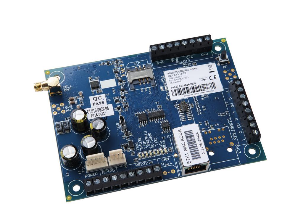
4 IRIS-4 6 Series Quick Installation and Maintenance Guide 3. Package Contents Contents dependent on model type: Dialler board Ethernet cable (IRIS & 640) 2/3/4G antenna (IRIS-4 640) 4. Board Configuration = 2/3/4G antenna 2 = Serial (TTL) 3 = RS485 4 = DC power 5 = S232 x 2 6 = Ethernet 7 = Pin inputs 8 = AP button 9 = Relays 10 = SIM card holder 11 = LEDs 12 = Micro USB
5 LED & Colour Indication SYS On Shows dialler is operational and all systems ok Flashing Shows the dialler has a system trouble On Dialler is seeing the SIM card (IRIS-4 640) Off Dialler not currently seeing the SIM card (IRIS-4 640) SIM GSM On GSM connected/registered (IRIS-4 640) Off GSM Not connected/registered (IRIS-4 640) GPRS/3G On 2/3/4G is attached to the network (IRIS-4 640) Off 2/3/4G is not attached to the network (IRIS-4 640) On ETH connected/synchronized Off ETH disconnected/not synchronized Flashing 0.2s On, 0.2s Off Shows not communicating with panel ETHERNET SERIAL Flashing 1.5s On, 1.5s Off Shows dialler not configured Flashing 0.1s On, 0.9s Off Shows normal communication POLL On Off Successfully polling with monitoring centre Note: Flickers off to show each poll Not polling with monitoring centre 5
6 IRIS-4 6 Series Quick Installation and Maintenance Guide 5. Before You Start Monitoring Centre (ARC) Make sure that the monitoring centre to which the IRIS-4 6 Series device will send alarm signals is equipped with the appropriate IRIS Secure Apps receiving system. The following information should be obtained from the Monitoring Centre. Dialler account number: Monitoring centre IP address: Ethernet Connection Details The customer s Ethernet (LAN) network details are required in order to connect the IRIS-4 6 Series. Obtain the following information from the customer. Fixed IP address or DHCP: Fixed DHCP If using DHCP then the following information will not be required as it will be assigned by the network. IP address: Gateway address: Subnet mask address: 2/3/4G SIM Card and Access Point Name If the installation uses 2/3/4G then a SIM card will be required. The IRIS will also need to be given a 2/3/4G Access Point Name (APN) and other possible configurations as shown below. Obtain these from the SIM card provider. Access Point Name (APN): User name (USR): Password (PWD): SIM Pin: Note: SIM cards with a SIM Pin will require a PC/Laptop connected via USB for configuration. 6
7 6. Installing the IRIS-4 6 Series Dialler 6.1. Mounting Choose a suitable location, taking into consideration the routing of both power and dialler interface cables, within the alarm panel or separate enclosure. Secure the dialler within the enclosure using the fitted standoff or the alternative self-adhesive feet. Note: For EN compliance, you must use the supplied standoff and not the self-adhesive feet Power The IRIS-4 6 Series dialler can be powered using a separate or Aux 9-28V DC power supply specified to deliver a minimum of 1A current using the screw terminals, or receive power directly via the 4 or 5 Pin Molex connector (RS485 or Serial TTL) headers indicated in Section 4 Board Configuration. Note: For Radio Equipment Directive compliance, the power cable must be no longer than 3 meters in length. Fit the power cable. DO NOT APPLY POWER TO THE DIALLER UNTIL INDICATED Connections Connect cables to the PCB for the system as shown on in Section 4 Board Configuration. Ethernet enabled systems: Connect the LAN1 connector using the Ethernet cable to the local IP router/switch or socket that has been allocated for the LAN/WAN network IP connection. 2/3/4G enabled systems (IRIS-4 640): Fit the supplied T-bar 2/3/4G antenna to the Cell Ant connector but do not fix in place until after performing the 2/3/4G network scan. 6 x Pin Inputs (optional for more information see section below). Optional serial connection The following 5 connections are optional and depend on the panel connection method to be used. By default, the IRIS-4 RS485 connection is for Honeywell Galaxy panels and the Serial TTL header is for Texecom Premier Panels. Note: For alternative panel manufacturers selection, you will need a Laptop/PC connected via USB to change the configuration of the IRIS-4 6 Series, please contact AddSecure for further details or download the full panel installation manual available from RS485 currently available for Honeywell Galaxy data bus (Alarms and Upload/download) or Risco ProSys bus (Upload/download) connections (optional). RS485 4pin header (Molex) currently available for Honeywell Galaxy data bus connections (optional). Serial (TTL) currently available for Texecom Com1 connections (optional). RS232 port 1 screw terminal (optional for Hayes command terminal). RS232 port 2 screw terminal (optional for integrated panel connection). For more details on the cable requirements/connections please see detail on next page. 7
8 IRIS-4 6 Series Quick Installation and Maintenance Guide RS485 connections (Honeywell Galaxy or Risco ProSys) You can use the screw terminal blocks or the four Pin headers (Molex). If using the screw terminals the connections are: IRIS-4 6 Series to Honeywell Galaxy panels IRIS RS485 screw terminals to galaxy Data Bus terminal 0V (Power) Galaxy (-) VIN (Power) Galaxy (+) A Galaxy (A) B Galaxy (B) IRIS-4 6 Series to Risco ProSys panels IRIS RS485 screw terminals to Risco Bus1 terminal 0V (Power) COM VIN (Power) AUX A YEL B GRN TTL connections (Texecom Premier Range) Ordered from AddSecure Description = Texecom Serial Cable Part No = TEX600 UL 1007#24 ST. WIRE, BROWN UL 1007#24 ST. WIRE, BLACK UL 1007#24 ST. WIRE, RED UL 1007#24 ST. WIRE, YELLOW 300 mm PEG 8
9 RS232 port 2 connections (HHL and ESPA) IRIS-4 6 Series to HHL panels IRIS RS232 screw terminals to hhl Com Port (X3) TX2 2 (RX) RX2 3 (TX) 0V 1 (GRD) IRIS-4 6 Series to ESPA panels IRIS RS232 screw terminals to DB9 Male connector (possible screw terminals) TX2 Pin 2 (RX) RX2 Pin 3 (TX) 0V Pin 5 (GRD) 9
10 IRIS-4 6 Series Quick Installation and Maintenance Guide /3/4G SIM card (IRIS-4 640) If you are using the 2/3/4G connection then insert the SIM card into the SIM cardholder Pin Inputs The IRIS-4 6 Series dialler has 6 pin inputs that can be used to generate alarm messages, These can be: Text messages via SMS (IRIS /3/4G). SIA, Contact ID or Fast Format alarm messages over IP to the Monitoring Centre. Note: You can also use the Pin alarm inputs when directly connected to an alarm panel via the dial capture, serial or RS485 connections. Via Sense Resistors It is also possible to link the contacts to the IRIS-4 6 Series dialler via sense resistors so that an open or short circuit tamper on the loop is detectable and the Monitoring Centre alerted. In this case, the connections made should be as shown below. Note: For this feature to work correctly it is essential to connect the resistor at the contact end of the loop and not the dialler end. The Monitoring Centre must also enable the monitoring of this facility on the dialler within the IRIS Secure Apps receiving system. Via Open/Close Contact Source Each pin input is designed to be connected in a loop via an open/close contact source from an alarm panel, or other device, to a reference ground pin available on the IRIS-4 6 Series dialler, as shown below. Opening the contact (i.e. loop is open circuit) generates an alarm signal. Closing the contact generates the equivalent restore signal. 10
11 6.6. Switch on 6.8. Configuration To confirm power is applied, look for the indicator SYS LED flashing yellow on. To configure the dialler, use any of the following methods: /3/4G Signal Strength (IRIS-4 640) Alarm panel integration e.g. Honeywell Galaxy (RS485 connection) Texecom Premier range (Serial TTL connection). Please refer to Section 6.9 Panel configuration. With the IRIS using the 2/3/4G communication you will need to perform a signal strength check, to confirm that in the current installation you have the required signal strength for a reliable connection. Press and hold the AP button which will allow you to see the current signal strength indicated across the LEDs. For a reliable 2/3/4G connection it is recommended that you have signal strength of 3 or more LEDs on as shown on the examples below: Signal strength too low Minimum signal strength Maximum signal strength If the signal strength is below or close to minimum then try to reposition the antenna or use an external high gain antenna to improve signal strength (if necessary). Rerun the signal strength test and reposition again if necessary to gain best signal strength possible. Once you have the required 2/3/4G signal strength you can then move onto the configuration. Note: Please configure the alarm panel first for connections to Honeywell Galaxy or Texecom Premier on the serial integration, as these will transmit configuration to the IRIS-4 6 Series dialler. For the Galaxy Flex installation, you will need to change the Bus selection in menu for IRIS and for IRIS and 640. For more details on the alarm panel integration, download the full panel installation manual from Connect the board s Micro USB connector to a laptop/pc running the IRIS Toolbox software. Download the IRIS Toolbox user guide from Note: If you want to use the IRIS-4 6 Series dialler for pin inputs only or HHL/ESPA serial connections then you will need to connect a Laptop/PC and configure the dialler using the IRIS Toolbox software, using the remote Touch screen and Installation Wizard. Defaulting If at any point a complete default of the dialler is required, use the following procedure: 1. Completely power down the IRIS-4 unit. 2. Now Press and hold down the AP button. 3. Reapply power whilst still holding down the AP button pushed down for another 10 seconds. 11
12 IRIS-4 6 Series Quick Installation and Maintenance Guide 6.9. Panel configuration Configurations of the IRIS-4 6 Series dialler with integration with certain panel manufacturers is possible, please find further details below: Configuration on Honeywell Galaxy Intruder Control Panel Range via RS485 The IRIS-4 6 Series dialler can simulate a Galaxy Ethernet Module (Comm s Mod 4) and remote keypad, for both Alarms and Remote Service Suite upload/download connection. Note: If you want to use the SMS messaging function from the Galaxy panel then you will need to emulate the external PSTN module, and setup the Galaxy External PSTN module settings see the IRIS Honeywell Galaxy Installation Manual, or the IRIS-4 6 Series Engineering Manual. For further information on both the Galaxy installation and Remote Service Suite upload/download connection, please refer to the IRIS Honeywell Galaxy Installation Manual, IRIS-4 6 Series Engineering Manual or IRIS Remote Service App Client User Guide for Honeywell Galaxy range available from Note: For 2/3/4G it is not possible to configure the settings (e.g. APN) from the Galaxy keypad as the Galaxy has no entry method. Connect the IRIS-4 dialler to the Galaxy Data bus as indicated in Section 6.3 Connection, then power up the Galaxy control panel, if not already powered up. IRIS with 2/3/4G connection: The 2/3/4G configurations are configurable via an SMS message from any mobile phone. If 2/3/4G is used, you will need to set the 2/3/4G APN at least, and possibly user name and password. Note: SIM cards with a SIM Pin will require a PC/ Laptop connected via USB for configuration. You can do this by sending a text message to the phone number of the SIM card. The text should be in the format: AT%G10= apn %I2= username %I3= password If no username, password required the text format would be as followed: AT%G10= apn %I2= %I3= %G90= Where the apn is the Access Point Name for the SIM, e.g. orangeinternet. The username is the user name and password is the password for the sim card if required. Confirm with SIM card provider if unsure. Note: Configure the 2/3/4G settings before the IRIS-4 6 Series is polling, as SMS configuration are rejected for security once the dialler is polling. Alternatively, the information can be set via the IRIS Toolbox software on a PC/Laptop, which connects via the Micro USB connector. This is available from The configuration menu on the Galaxy panel that will need to be configured are located at menu option 56 (Communications), please enter the required information. Below is an example for the Galaxy Dimension v6.75 and above for other variant in both type e.g. Flex, Classic, G3, G2 or software version please refer to the IRIS-4 6 Series Engineering Manual. You must enter Engineer Mode on the Galaxy to access these options. 12
13 56 = Communication 4 = Ethernet 01 = Module Config 1 = IP Address Program in the IP address for the IRIS e.g = Site Name Leave blank 3 = Gateway IP Enter the network gateway IP address e.g = Network Mask Enter the subnet mask e.g Note: If you are using a DHCP address then leave all Module Config addresses blank 02 = Alarm Reporting 1 = Format Set to SIA level 3 2 = Primary IP 1 = IP Address Set this to the IP address of the Monitoring Centre e.g = Account No. Enter in the account number allocated by the Monitoring Centre Note: Secondary IP address not required as this will be download by the IRIS Secure Apps system 03 = Remote Access 1 = Access Period Set to 4 Any Time 2 = Mode Set to Direct Access if making calls into site from Honeywell Remote Service Suite (RSS) for remote access directly or via the IRIS Remote Service App client. Set to MGR Authorise if making the remote access calls out from site to the Honeywell RSS, and then set the call IP1 IP address to the IP address for the Honeywell RSS communication server e.g Note: Does not support the Honeywell Encryption so please ensure the following 2 options are turned off. 9 = Encrypt 1 = Alarm Report Set to Off 2 = Remote Access Set to Off 13
14 IRIS-4 6 Series Quick Installation and Maintenance Guide After you have entered in the relevant information, exit Engineer Mode and the panel should now detect 2 new RS485 modules (Comms Mod and Remote Keypad (Dimension, G3, G2 and Classic panels)). If the new modules are not detected then you may need to power off the Galaxy panel, check the dialler connections, and power back on. Now go back into Engineer Mode and send an ETHERNET ENGINEER TEST Alarm (refer Galaxy Dimension/Flex Installation Manual). Check to see if the Monitoring Centre has received this test alarm. Note: If you are required to default the IRIS-4 dialler and start again you can do this by setting the primary IP address within the Galaxy menu or Galaxy Flex menu to an IP address of and then send an Engineer test alarm. You can now perform the alarm signals commissioning and sign off required by the Monitoring Centre. Configuration from Texecom Premier panels via Serial TTL The IRIS-4 6 Series has been fully integrated into the Texecom Premier Alarm panel range and most configurations can be configured from the panel keypad. Note: 2/3/4G connections you will need to enter in the 2/3/4G settings (e.g. APN). With the latest integration on the Texecom Premier Elite panel, this configuration is possible via the keypad. For older/different models, it is currently not possible to configure the 2/3/4G settings (e.g. APN) from the keypad, as the Texecom has no entry method. Connect the IRIS-4 6 Series dialler via the TTL header to a free Texecom Com port header as indicated in Section 6.3 Connections, then power up the Texecom panel, if not already powered up. IRIS with 2/3/4G connection: The 2/3/4G configurations are configurable via an SMS message from any mobile phone. If 2/3/4G is used, you will need to set the 2/3/4G APN at least, and possibly user name and password. Note: SIM cards with a SIM Pin will require a PC/ Laptop connected via USB for configuration. You can do this by sending a text message to the phone number of the SIM card being used. The text should be in the format: AT%G10= apn %I2= username %I3= password If no username, password required the text format would be as followed: AT%G10= apn %I2= %I3= %G90= Where the apn is the Access Point Name for the SIM, e.g. orangeinternet. The username is the user name and password is the password for the sim card if required. Confirm with SIM card provider if unsure. Note: Configure the 2/3/4G settings before the IRIS-4 6 Series is polling, as SMS configuration are rejected for security once the dialler is polling. On the next page is a detailed description of the configuration setting for the latest Texecom Premier Elite range. If you have different version of the Texecom Premier Range or want to perform upload/ download connection via Wintex then please refer to the IRIS-4 6 Series Engineering manual, IRIS Texecom Premier Installation manual or IRIS Remote Service App Client User Guide for Texecom range from 14
15 Texecom Premier Elite Series (12, 24, 48, 88, 168, 640) 7 = UDL/DIGI Options 3 = Program Digi Arc 1 Protocol Set to the alarm format requested by the Monitoring Centre or customer i.e. Fast Format, Contact ID, or SIA level 2/3. Primary No Set this to the IP address of the Monitoring Centre in a 12 digit format i.e = Secondary No Leave blank as the IRIS System will receive the secondary number from the Monitoring Centre IRIS Secure Apps system. Account Number Enter in the account number allocated from the Monitoring Centre. Dialler Attempts Leave as the default 3. Report options The reporting options will change depending on the alarm format selected, please set up the various reporting option for the alarm event you wish to send to the Monitoring Centre. Config 1 Enable the Connect via IP (Key press 7). Config 2 Select the Com port the IRIS-4 6 Series dialler is connected to. (version 4 and above) 4 = Digi Options Enable the Digi (key press 1) should now see E on keypad option screen now. 5 = UDL Options 4 = UDL Password Must match the UDL password setup within Wintex. 6 = Ring Count Set to 1 for use with the IRIS Remote Service App. 7 = Setup Modules 2 = Setup IP Data Note: To use DHCP please leave the ComIP Address and Gateway blank/default values. 1 = ComIP Address Program in the IP address for the IRIS in a 12 digit format i.e = = ComIP Port Program the Port number for Wintex connection normally = ComIP Gateway Enter the network gateway IP address in a 12 digit format i.e = = ComIP Netmask Enter the network subnet mask i.e = Polling/SMG IP Set this to the IP address of the Monitoring Centre in a 12 digit format i.e = = Setup GPRS Data 0 = Access Pnt Name Enter the 2/3/4G access point name for the SIM card you are installing. 1 = User Name Enter the user name for the SIM card if assigned. 2 = Password Enter the password for the SIM card if assigned. 8 = Com Port Setup 2 = Com Port 1 Set to IRIS IP Module. You can now perform the alarm signals commissioning and sign off required by the Monitoring Centre. 15
16 IRIS-4 6 Series Quick Installation and Maintenance Guide Testing Once all configurations are complete, perform a full commissioning test with the Monitoring Centre. This will normally involve testing normal alarm transmissions from the alarm panel over all communication paths to the Monitoring Centre. Verifying acknowledgement of these alarms with the operators at the Monitoring Centre. 7. Maintenance There is no requirement for any onsite maintenance on the IRIS-4 6 Series. If engineers want to carry out a maintenance inspection, please perform the following: Confirm the status of the IRIS-4 6 Series unit. Clear any faults on the dialler. Test the configured communication paths (Ethernet and/or 2/3/4G). Perform full test of alarms from the alarm panel and confirm acknowledgement of these by the operators at the monitoring centre. The IRIS-4 6 Series dialler will give a visual indication of the current system status via the SYS LED. If this is yellow constant the current setup of the dialler is reporting OK, yellow flashing means the dialler is reporting some trouble events. SYS LED: Yellow Constant = OK Yellow Flashing = Dialler is reporting some trouble events 7.1. Confirm Current Status The IRIS-4 6 Series will indicate the status via the LEDs as per the information in Section 4 Board Configuration. For further information, please refer to the IRIS-4 6 Series Engineering Manual available from 16
17 7.2. Communication Path Checks and Communication to Monitoring Centre Test communication paths for both polling and alarm communications by using the following procedure: Confirm Poll LED On Test Alarm Panel Alarms and Communication to Monitoring Centre Depending on the Monitoring Centre, engineers will now be required to perform alarm test and possibly other tests to the Monitoring Centre. Before leaving site, the engineer should obtain confirmation from the Monitoring Centre that all is working correctly. For the IRIS dual path only Remove 2/3/4G antenna and confirm after 3 minutes that the GSM & GPRS/3G LED are Off. Confirm Poll LED still On. Send an alarm from the alarm panel and confirm acknowledgement from the Monitoring Centre. This confirms the Ethernet path is functioning correctly. For the IRIS dual path only Reconnect the 2/3/4G antenna and wait approximately 5 minute and then confirm that the GSM & GPRS/3G LED are now On. Disconnect the Ethernet connection to the dialler and confirm after 3 mintues that the Ethernet LED is Off. Send another alarm from the alarm panel and confirm acknowledgement from the Monitoring Centre. This confirms the 2/3/4G path is functioning correctly. Reconnect the Ethernet and wait approximately 5 minutes and confirm the Ethernet LED is now On. If you have an IRIS with dual paths enabled repeat these tests for the other communication path. 17
18 IRIS-4 6 Series Quick Installation and Maintenance Guide 8. Specifications Transmission paths Ethernet Standard UTP 10/100 Base T with auto-negotiation Connection Rj45 socket for CAT5 cabling IP addressing Dynamic (DHCP) or fixed Fault detection Loss of Ethernet synchronisation 2/3/4G Frequencies Penta band LTE (4G) 800/900/1800 MHz 2100/2600 MHz Dual band UMTS (3G) 900/2100 MHz Dual band GSM (2G) 900/1800 MHz Connection SMA socket for antenna Fault detection Loss of registration with network IP TCP ports (outbound) (Alarms & Polling), (Diagnostic & Reflashing), (Upload/Download) 18
19 Transmission paths Alarm transmission Interface to Monitoring Centre IRIS Secure Apps or IRIS Management Suite via EN pass-through mode RS485, TTL, RS232 x 2 Note: RS232 cabling must not exceed 30 meters Serial interface to alarm panel PIN Inputs interface to alarm panel Maximum input voltage range 0V to +24V Input low (alarm) threshold < 1V Input high (restore) threshold > 2V Internal pull-up impedance 10K to 3.3V supply Alarm protocols SIA (level 1 to 3) reference SIA DC (R ) Contact ID reference SIA DC Fast format (Scancom) Tamper detection reporting to Serial interface, Pin inputs Monitoring Centre Fault reporting to Monitoring Centre Transmission interface/path fault Note: Cabling must not exceed 3 meters Relay outputs Maximum operating voltage 24V DC Maximum current rating 100mA DC Power supply Supply voltage 9V to 28V DC Typical current 12V DC 12V DC Maximum current 12V DC Recommended external PSU 12V DC 1A 12 Watt Note: For Radio Equipment Directive the power cable needs to be no longer than 3 meters in length Environmental Operating temperature range -10 C to 55 C Operating humidity range 95% max., non-condensing Weights and dimensions Physical dimensions 12 cm x 9 cm PCB weight 60 grams Fully packaged weight 160 grams 19
20 Safety Care should be taken when connecting telecommunications equipment to ensure only like interfaces are connected to avoid safety hazards. SELV: SELV (Safety Extra-Low Voltage) is defined as a secondary circuit which is so designed and protected that under normal and single fault conditions the voltage between any two accessible parts does not exceed a safe value (42.4V peak or 60V dc maximum) INNEHOLD: INNEHÅLL: The interfaces on the IRIS have the following safety classifications: Airborne DC kretskort Airborne DC kretskort Power Interface: SELV for connection to a DC supply Mål (BxHxD): 58x105x25 mm (BxHxD): Mått 58x105x25mm Inputs: SELV for connection to alarm output pin. Ladekort Laddkort Plastkabinett,sabotasjesikret. Mål (BxHxD): 170x160x60 mm Conformance Plastkapsling,sabotagesäker. Mått (BxHxD): 170x160x60mm 1stk. NiMH 2200 mah batteri 1st. NiMH 2200 mah batteri European Directives Ekstern 15 VDC strømadapter 15 VDC strömadapter The IRIS-4 6 Series complies with the following EuropeanExtern Directives: Integrerat SIM-kort (e-sim) med tillhörande AddSecureabonnemang Integrert SIM-kort (e-sim) med 2014/53/EU (Radio Equipment Directive) tilhørende AddSecure abonnement 2013/35/EU (Electromagnetic Fields) 2004/108/EC (CE directive) Hurtigmanual 2002/96/EC (WEEE) Informasjonog support 2011/65/EC (ROHS) Internantenne Monteringsskruer Monteringsskruvar Dekaler Alarmetikett CONTACT AND SUPPORT Snabbguide Informationoch support Internantenn Installation and Service Engineer Support Telephone: (Calls are charged 13 pence per minute plus your phone company s access charge) Sales enquiries: iris.support@addsecure.com The information contained is supplied without liability for any errors or omissions. No part may be reproduced or used except as authorized by contract or other written permission. The copyright and foregoing restriction on reproduction and use extend to all media in which the information may be embedded AddSecure EN50131, EN50136 (VdS Certified) The dialler is compliant with the requirements of European Standards: GODKJENNELSER/GODKÄNNANDE EN : 2006+A2:2017 & EN :2014 EN : Type & EN : 2013 EN54-21:2006 EN :2011 EN :2012 EN :2011 Security GradeATS: 4 SP4 EN :2013 SBF110:7 ATS-SP6 over Ethernet, ATS-SP5 over 2/3/4G, ATS-DP4 (IRIS-4 640) EN :2006/A1:2009 R2 ECII g SSF114:2 Larmklass 2 Environmental Class II UMTS: ATS CPr -P20727-F03-16
IRIS Touch Quick Installation & Maintenance Guide. Version 1.0
 IRIS Touch Quick Installation & Maintenance Guide Version 1.0 Contents 1. Introduction... 3 2. Product Features... 3 3. Package Contents... 4 4. Board Configuration... 4 5. Before You Start... 5 6. Installing
AIRBORNE IRIS-4. Series. Installation and. Hurtigmanual/
 AIRBORNE IRIS-4 4DC Series MEDIUM Quick Installation and Hurtigmanual/ Maintenance Snabbguide Guide Contents 1. Introduction...3 2. Product Features...3 3. Package Contents...4 4. Board Configuration...4
IRIS Touch Quick Installation & Maintenance Guide. Version 1.0
 IRIS Touch Quick Installation & Maintenance Guide Version 1.0 Page 2 of 16 IRIS Touch Quick Installation & Maintenance Guide Version 1.0 Contents 1. Introduction... 4 2. Product Features... 4 3. Package
IRIS Touch Quick Installation & Maintenance Guide. Version 1.0
 IRIS Touch Quick Installation & Maintenance Guide Version 1.0 Page 2 of 16 IRIS Touch Quick Installation & Maintenance Guide Version 1.0 Contents 1. Introduction...4 2. Product Features...4 3. Package
IRIS Touch Quick Installation & Maintenance Guide. Version 1.6
 IRIS Touch Quick Installation & Maintenance Guide Version 1.6 Page 2 of 16 IRIS Touch Quick Installation & Maintenance Guide Version 1.6 Contents 1. Introduction...4 2. Product Features...4 3. Package
The future of security, secured IP by security professionals, for the professional security industry
 The future of security, secured IP by security professionals, for the professional security industry Installation and Service Engineer Support Telephone: +44 871 977 1133 (Calls are charged at 10p a minute
600 Range Dialer Installation Manual. Version 1.0
 600 Range Dialer Installation Manual Version 1.0 The information contained is supplied without liability for any errors or omissions. No part may be reproduced or used except as authorised by contract
IRIS Touch Engineering Manual. Version 1.2
 IRIS Touch Engineering Manual Version 1.2 Contents 1. Introduction... 3 2. IRIS Communication Mechanism (Polling / Alarms)... 4 3. Product Features... 5 4. Package Contents... 6 5. Board Configuration...
IRIS Touch Engineering Manual. Version 1.2
 IRIS Touch Engineering Manual Version 1.2 Contents 1. Introduction... 3 2. IRIS Communication Mechanism (Polling / Alarms)... 4 3. Product Features... 5 4. Package Contents... 6 5. Board Configuration...
IRIS Connect Series Quick Installation & Maintenance Guide. Version 1.1
 IRIS Connect Series Quick Installation & Maintenance Guide Version 1.1 Contents 1. Introduction... 4 2. Product Features... 4 3. Package Contents... 5 4. Board Configuration... 5 5. Before You Start...
IRIS Touch 400 & 600 Range Installation Manual. Honeywell Galaxy Range. Version 2.0
 IRIS Touch 400 & 600 Range Installation Manual Honeywell Galaxy Range Version 2.0 Table of Contents 1 System Overview... 4 2 IRIS Touch 440 & 640 PCB Layout... 5 3 Connection & Configuration for Honeywell
IRIS Touch 200 Range Dialler Installation Manual. Version 1.4
 IRIS Touch 200 Range Dialler Installation Manual Version 1.4 The information contained is supplied without liability for any errors or omissions. No part may be reproduced or used except as authorised
IRIS Touch Firmware Enhancements and Additions from Version to Version
 Overview IRIS Touch Firmware Enhancements and Additions from Version 1.14.3 to Version 1.19.1 This document details enhancements to the feature set of the IRIS Touch from firmware Version 1.14.3 to Version
SC-F3G User Manual 1.0
 SC-F3G User Manual 1.0 Table of Contents 1. Introduction... 3 2. Functions... 3 3. Features... 3 4. Package Contents... 3 5. Device Configuration... 4 6. Status LED signals... 5 7. Before You Start...
DigiAir QUICK GUIDE & INSTRUCTION MANUAL
 DigiAir QUICK GUIDE & INSTRUCTION MANUAL The most trusted brand in Alarm Signalling www.csldual.com @CSLDualCom CSL DualCom Limited Figure 1 - DigiAir Yellow Comms LED Red Fault LED Yellow Service LED
DualCom GradeShift UDL QUICK GUIDE & INSTRUCTION MANUAL
 DualCom GradeShift UDL QUICK GUIDE & INSTRUCTION MANUAL The most trusted brand in Alarm Signalling www.csldual.com @CSLDualCom CSL DualCom Limited Figure 1 - GradeShift UDL SIM card slot Service LED Aerial
GLOBAL. InstallatIon & operation manual
 InstallatIon & operation manual INDEX 1. INTRODUCTION... 5 2. FEATURES AND FUNCTIONS 2.1 Reporting Options... 2.2 Interfaces... 2.3 Programming... 2.4 Indicators and Controls...... 6 6 6 6 6 3. INSTALLATION...
Remote Service App. Client Installation and Operation Guide V1.1
 Remote Service App Client Installation and Operation Guide V1.1 Table of Contents 1 Background... 1 2 System Overview... 2 3... 4 3.1 Installation... 4 3.2 Set up... 8 3.3 Operation... 11 4 Technical Details...
T4000 Security Communicator
 Inner Range T4000 Security Communicator 1 T4000 Security Communicator by Inner Range P/N: 998530 / 998530NZ 998530LT (Lite Version) Installation & Operation Manual. Rev: 1.5 Inner Range Pty. Ltd. www.innerrange.com
UC-351. Installation, Maintenance and Operational Manual. Model UC-351GH, UC-351-3GH
 UC-351 Installation, Maintenance and Operational Manual Model UC-351GH, UC-351-3GH UltraConnect UC-351 Edition 09 Copyright UHS 2009 Installation Manual Page 1 All rights reserved. TABLE OF CONTENTS 1
Faster and smarter ways to protect what matters most. Our Next Generation portfolio
 Faster and smarter ways to protect what matters most Our Next Generation portfolio 2 Contents 3 Why Redcare 4 Say hello to our Next Generation portfolio 5 How our new products stack up 6 Get to know Essential
PERMACONN PM1030 Includes DI300. Installation Manual
 PERMACONN PM1030 Includes DI300 Installation Manual Radio Data Comms Unit 5/20-30 Stubbs Street Silverwater NSW 2128 Telephone: 02 9352 1777 Facsimile: 02 9352 1700 Introduction The PERMACONN system provides
IP & SMS Alarm Communicator
 Models: WGSMSC You deserve to feel safe, secure & protected IP & SMS Alarm Communicator Quick Start Guide Thank you for purchasing a Watchguard IP & SMS Alarm Communicator This Quick Start Guide covers
GRADESHIFT UDL INSTRUCTION MANUAL 2.5 APPENDIX
 GRADESHIFT UDL INSTRUCTION MANUAL 2.5 APPENDIX GradeShift UDL Instruction Manual 2.5 Appendix 2.5 APPENDIX SPECIFICATIONS Dimensions 21 mm (h), 132mm (w), 94mm (d) Weight 140g including NVM and SIM Temperature
AZWG10200 ABUS PSTN/IP converter
 AZWG10200 ABUS PSTN/IP converter EN Version 1.0 AZWG10200 Preface Dear Customer, Thank you for purchasing this PSTN/IP converter. This device is built with state-of-the-art technology and complies with
PERMACONN PM1048 v3 3G Install Manual Australia
 PERMACONN PM1048 v3 3G Install Manual Australia Radio Data Comms Unit 5/20-30 Stubbs Street Silverwater NSW 2128 Telephone: 61 2 9352 1777 Facsimile: 61 2 9352 1700 Table of Contents Introduction / Features
Fratech Multipath-IP
 Rev 2.0 (May 2013) Installer Manual 1 Current Part Numbers: Fratech Multipath-IP E-Link STU PCB & Accessory Kit only In Metal Enclosure with Power Supply 998325-PK 998325-XS Installer Manual This document
Fratech Multipath-IP STU
 Rev 2.41 (September 2008) Installer Manual 1 Fratech Multipath-IP STU P/Nos: Single SIM: 998304OPT/998304TEL Dual SIM: 998307OPT/998307TEL Installer Manual This document contains a product overview, specifications
Installation, Maintenance and Operation Manual
 Installation, Maintenance and Operation Manual (for Intruder and fire use) Secure Mk3 GPRS and 3G LPS 1277: Issue 3 Cert No. 1270c Cert No. 1270d Table of Contents Introduction 3 Mounting And Wiring 5
Telemetry Communications Device. Installation Guide. Interface for the Emizon managed network. Issue 1: February 2008
 TCD Telemetry Communications Device Installation Guide Interface for the Emizon managed network Issue 1: February 2008 This guide sets out a simple check list together with a step-by-step guide to the
Emizon TCD. INSTRUCTION Manual
 Emizon TCD INSTRUCTION Manual FOR IP/GPRS GPRS/PSTN & IP/PSTN For alarm control panels using up to 16 pins, RS232, RS485 and Dial Capture. For compliance with EN alarm signalling Grade 2, 3, 4, BS 8418
COMMUNICATOR ET08 / ET081
 COMMUNICATOR ET08 / ET081 User Manual v1.2 Safety instructions Please read and follow these safety guidelines in order to maintain safety of operators and people around: GSM communicator ET08 / ET081 (further
BAT WIFI SKU: IPD-BAT--WIFI
 PRODUCT MANUAL BAT WIFI SKU: IPD-BAT--WIFI Wi-Fi & Internet Alarm Communicator www.ipdatatel.com Product Manual BAT WIFI 1 QUICK REFERENCE BAT-WIFI GE Control Panel POS Com Data 6 5 4 3 G / Rx Y / Tx -
Any additional devices linked to the system ET08 (computer, sensors, relays etc.) must be approved by LST EN standard.
 must be approved by LST EN standard.") COMMUNICATOR ET08 User Manual v1.0 Safety instructions Please read and follow these safety guidelines in order to maintain safety of operators and people around: GSM communicator (gateway) ET08 (further
COMMUNICATOR ET08 User Manual v1.0 Safety instructions Please read and follow these safety guidelines in order to maintain safety of operators and people around: GSM communicator (gateway) ET08 (further
Inner Range FE3000S. Serial GSM Modem. P/No: INSTALLATION MANUAL
 Revision 1.0 October. 2014 1 Inner Range FE3000S Serial GSM Modem. P/No: 998306 INSTALLATION MANUAL IMPORTANT NOTE: This Installation Manual is only relevant to Serial GSM Modems utilizing the G-Link PCB.
Centaur TM II Cube Slave Alarm Signalling Equipment INSTALLATION GUIDE
 Centaur TM II Cube Slave Alarm Signalling Equipment INSTALLATION GUIDE General Description This guide provides a summary for installing and configuring the Centaur TM Cube Slave Alarm Signalling Equipment
EC-P Zone Intruder Alarm System
 EC-P10 10-20 Zone Intruder Alarm System Installation Manual Contents 1. System Overview... 4 System Configuration... 4 Control Panel... 5 Remote Keypads... 5 EC-LED Remote Keypad... 5 EC-LCD Remote Keypad...
WEBWA al Y arm 2 sig 4 nall2 in 4
 EBWAY 2424 alarm signalling WebWay 2424 page 3 WebWay 2424 MANAGED SERVICES WebWay 2424 managed alarm signalling improves security and site management using the latest communications technology saving
IndigoVision Alarm Panel. User Guide
 IndigoVision Alarm Panel User Guide THIS MANUAL WAS CREATED ON 2/21/2017. DOCUMENT ID: IU-AP-MAN002-4 Legal considerations LAWS THAT CAN VARY FROM COUNTRY TO COUNTRY MAY PROHIBIT CAMERA SURVEILLANCE. PLEASE
Security Alarm Systems
 eclipse Security Alarm Systems Contents Introduction 2 System Configuration 3 Control Panels 4 Remote Keypads & Expanders 5 Communication Modules 6 Upload/Download 6 Specifications 7 Introduction Zeta
For business, corporate and public sector security. Protected premises, protected network
 WebWay GPRS/PSTN LPS I&HAS ATS4 PLUS For business, corporate and public sector security Reduce costs, not security Protected premises, protected network Certified and compliant to LPS1277 Issue 3; the
GradeShift UDL QUICK GUIDE & INSTRUCTION MANUAL
 GradeShift UDL QUICK GUIDE & INSTRUCTION MNUL This guide contains information taken from the UDL Installation Manual. full copy of the manual can be downloaded from www.csldual.com. Please note that all
Emizon TCD. INSTRUCTION Manual
 Emizon TCD INSTRUCTION Manual FOR IP/GPRS GPRS/PSTN & IP/PSTN For alarm control panels using up to 16 pins, RS232, RS485 and Dial Capture. For compliance with EN alarm signalling Grade 2, 3, 4, BS 8418
Security designed for your lifestyle
 Security designed for your lifestyle The Paradox Insight : The Big Picture A single CAT5 or higher cable can be used to wire a single HD77 camera. Camera Detector Module HD 720p camera Quad PIR with auto
BAT LTE SKU: IPD-BAT-LTE
 PRODUCT MANUAL BAT LTE SKU: IPD-BAT-LTE Universal Internet & Cellular 4G LTE Alarm Communicator Technical Support Information For Technical Support, call toll free: (888) 88-ALULA alula.net www.alarmdealer.com
GRADESHIFT UDL INSTRUCTION MANUAL
 GRADESHIFT UDL INSTRUCTION MANUAL GradeShift UDL Instruction Manual 1. Quick Guide Figure 1 - GradeShift UDL Figure 2 - LED Indications STEP 1. SITE SURVEY Use a Signal Analyser (available from the CSL
EURO 46 V10 User Manual
 EURO 46 V10 User Manual PD6662:2010+IA501:2015 EN50131-1:2008+A1:2009 EN50131-3:2009 Security Grade (SG) 3 - Large Security Grade (SG) 2 - Small Environmental Class (EC) II Software Version >10 RINS1943-1
ibox Modbus Server Gateway for the integration of Notifier ID3000 / ID3002 / ID60 / ID50 fire panels in Modbus enabled monitoring and control systems
 Honeywell Life Safety Iberia C/Pau Vila 15-19; 08911 Badalona Barcelona T. 902 03 05 45; Internacional:+34932424236 www.honeywelllifesafety.es infohlsiberia@honeywell.com ibox Modbus Server Gateway for
Preface. Thank you for purchasing our GSM Security Alarm System ( The System )! The System will keep your home and property safe around the clock.
! The System will keep your home and property safe around the clock.") Preface Thank you for purchasing our GSM Security Alarm System ( The System )! The System will keep your home and property safe around the clock. The GSM Security Alarm ( The Alarm ) adopts the most advanced
Preface Thank you for purchasing our GSM Security Alarm System ( The System )! The System will keep your home and property safe around the clock. The GSM Security Alarm ( The Alarm ) adopts the most advanced
IntesisBox BACnet/IP Server - Notifier ID3000 series
 IntesisBox Server - Notifier ID3000 series Gateway for integration of Notifier ID3000, ID3002, ID50 and ID60 fire panels into enabled control systems. Integrate your Notifier fire panels into your BACnet
DigiPlus INSTRUCTION MANUAL
 DigiPlus INSTRUCTION MANUAL Introduction DigiPlus DigiPlus is a converter for use with Digital Communicators (and Control Panels with built-in Digital Communicators) that use Fast Format DTMF signalling
installation & operation manual
 installation & operation manual TABLE OF CONTENTS INTRODUCTION... 2 FEATURES... 2 PROGRAMMING CONTACT ID... 3 INSTALLATION... 3 OPENING THE HAWK COVER... 3 POWER SUPPLY... 5 CHECK AC... 5 DRY CONTACTS
Instructions manual. By-alarm. By-alarm Manager software
 Instructions manual By-alarm By-alarm Manager software Index 1. Procedure for the complete programming of the By-alarm system 5 Operations to be carried out prior to the programming with By-Alarm Manager
CG500SKE SKYEYE GATEWAY USER MANUAL VERSION OCTOBER Disclaimers and Copyright
 CG500SKE SKYEYE GATEWAY USER MANUAL CG500SKE SkyEYE Gateway VERSION 1.2 26 OCTOBER 2014 Disclaimers and Copyright Nothing contained in this publication is to be construed as granting any right, by implication
English. Doro CareIP Mobile. User Guide
 English Doro CareIP Mobile User Guide 1. Read first: Safety information Always read and follow the safety information accompanied by this symbol. User s should pay particular attention to the potential
Installation Manual. ATS Remote Annunciator Catalog 5350 DANGER WARNING D
 ASCO 5350 The ASCO 5350 ATS Remote Annunciator is listed under the Underwriter s Laboratories Standard UL-1008 for Automatic Transfer Switch accessories. This stand-alone device provides individual status
MiNi Server environment MoNitoriNg SySteM
 enviromux-mini with enviromux-t-3 temperature Sensor Features & Applications Monitors threats: temperature Humidity Water Leakage intrusion The ENVIROMUX Mini Server Environment Monitoring System monitors
Installation Manual. Premier 640. Issue 1
 Installation Manual Premier 640 Issue 1 Contents Contents 1. New Features... 4 Area Profiles... 4 User Profiles... 4 Access Profiles... 4 User Programming... 4 Default Settings... 4 Mandatory Log... 4
HOME MANAGEMENT GATEWAY
 LS-20 The Universal Box HOME MANAGEMENT GATEWAY OPERATION MANUAL V1.00 INTRODUCTION Thank you for purchasing the LS-20 the Universal Home Management Gateway. By adopting modern embedded system and Cloud
Technical Bulletin Bulletin Number: 2012_02 Released: 1 st May 2012
 RX / QX V4.51 and PX V5.00 UTC Climate, Controls and Security Systems is pleased to announce the release of Version 4.51 for the RX / QX (Grade 2) control panels, and Version 5.00 for the PX (Grade 3)
SCR100 User Manual. Version:1.1 Date:Dec 2009
 SCR100 User Manual Version:1.1 Date:Dec 2009 Introduction: This document mainly introduces the installations and connections of SCR100 products, and the brief operations about attendance software. Important
Sentient. Downloader Manual D4854
 Sentient Downloader Manual D4854 Dycon Ltd Tel: +44 (0)1443 471 060 Fax: +44 (0)1443 479 374 Cwm Cynon Business Park Mountain Ash CF45 4ER - UK www.dyconsecurity.com sales@dyconsecurity.com TABLE OF CONTENTS
GSM RFID VOICE Alarm System
 GSM RFID VOICE Alarm System User s Manual For a better understanding of this product, please read this user manual thoroughly before using it. CONTENTS [Function Instruction] [Control Panel] Control Panel
Сontrol panel Contact GSM-9N
 Сontrol panel Contact GSM-9N Data sheet Device identification number 2 1. General Information The Contact GSM-9N control panel (hereinafter referred to as the device) is designed for setting up security
Easy Series ICP-EZM2. System Reference Guide
 Easy Series ICP-EZM2 en System Reference Guide Easy Series Table of Contents en 3 Table of Contents 1 Overview 6 1.1 Installation Workflow 6 1.2 System Components and Wiring 6 1.3 Phone Menus 10 1.3.1
ModBus DE-1 INSTALLATION AND USER MANUAL
 ModBus DE-1 INSTALLATION AND USER MANUAL INTESIS Software, SL Distributed by DURAN ELECTRONICA S.L Tomás Bretón 50 28045 MADRID, España duran@duranelectronica.com www.duranelectronica.com 2 2010 DURAN
ET082 GSM/GPRS COMMUNICATOR
 ET082 GSM/GPRS COMMUNICATOR User Manual v2.2 Valid for ET082 v01.14.00 and up; hardware version: ET082-30 and up. SAFETY INSTRUCTIONS Please read and follow these safety guidelines to safeguard yourself
Technical Manual The Next Generation Nano
 Technical Manual The Next Generation Nano March 2017 Version 1.0 WebWayOne Ltd, Kingfisher Court, Hambridge Road, Newbury, Berkshire. RG14 5SJ. www.webwayone.co.uk www.webwayworld.com Quick start for The
SMS GSM Alarm Messenger
 SMS GSM Alarm Messenger Data Logging Alarm Input Relay Output Voice Temperature Humidity Analog Input Capture and Send Data via SMS Report triggered alarm via SMS Output triggered via SMS Auto pick up
Smart Wireless Sensor
 Smart Wireless Sensor G7 G7 creates the IoT platform of sensor data exchange and integration 64 wireless sensors each station * temperature, humidity, analog sensors, or digital alarm Windows / ios / Android
Ethernet General Purpose
 Ethernet General Purpose Technical Manual Revision 1.03 8 November 2013 Pakton Technologies IO PAE224 Ethernet GPIO Manual.docx Page 1 of 22 Revision 1.03 Last updated 8/11/2013 Table of Contents INTRODUCTION...3
Memcom Emergency Telephone
 Memcom Emergency Telephone Installation Guide Ref No. 450 900 (GB) Version 2 + + Simple wiring for quick installation + + Integrated LCD display shows you what you have programmed + + All code based programming
Revision November 2013 JVA Technologies. Ethernet General Purpose IO Technical Manual
 Revision 1.03 8 November 2013 JVA Technologies Ethernet General Purpose IO Technical Manual www.jva-fence.com.au Table of Contents INTRODUCTION...3 Scope and Purpose...3 Glossary...3 SPECIFICATIONS...4
Monitoring Solutions
 GSM Systems Monitor: Temperature, Humidity, Power, Water, Smoke, Carbon Monoxide and More September 2016 Table of Contents GSM Systems... 3 Argon 100 GSM... 3 Ares 12 & 14 GSM... 4 Poseidon2 4002... 5
Advisor Advanced Mobile Application User Manual
 Advisor Advanced Mobile Application User Manual Content Warnings and Disclaimers 2 Advanced Mobile 2 Contact information 2 Description 2 Screen navigation 4 Gestures 4 Menu 4 Help navigation 4 Login 5
Cold chain monitoring technologies. Facility monitoring
 Cold chain monitoring technologies Facility monitoring Advanced wireless data logging system - Cobalt For various controlled environment facilities, equipments and transport conditions, real time monitoring
Remote switching machines with a SMS text from your mobile phone! Remote Monitoring your assets in the worldwide by your mobile Phone!
 Remote switching machines with a SMS text from your mobile phone! Remote Monitoring your assets in the worldwide by your mobile Phone! GSM SMS Controller DCS-130 User Manual Ver 1.20 Date Issued: 14-9-2010
Smart Hub. User & Installation Guide
 Smart Hub User & Installation Guide Your Tunstall Smart Hub The Tunstall Smart Hub is connected to the mains power supply and has a builtin battery in case of mains power failure. The Smart Hub connects
3G GSM AUTO DIALER. Remote monitoring & Control using your mobile phone. MODEL NUMBER 3GAD1
 3G GSM AUTO DIALER Remote monitoring & Control using your mobile phone www.gsm-activate.co.uk MODEL NUMBER 3GAD1 PAGE 1 Product Information Our 3G GSM Auto Dialer is a versatile unit which can be attached
Instruction manual MTL process alarm equipment. October 2016 CSM 725B rev 2 MTL RTK 725B. Configuration Software Manual
 Instruction manual MTL process alarm equipment October 2016 CSM 725B rev 2 MTL RTK 725B Configuration Software Manual SECTION 1 - INTRODUCTION... 5 Basic Requirements... 5 SECTION 2 - SOFTWARE INSTALLATION...
Universal Monitoring System. Model IMEC8A. User Manual Version 1.10 Software version 2.3.1
 Unit 7/8, Heathrow Causeway Estate, Ariel Way, Hounslow Middlesex, TW4 6JW +44 (0) 208 6302270 www.cpcuk.co.uk Universal Monitoring System Model IMEC8A User Manual Version 1.10 Software version 2.3.1-1
Installation Manual. for D2300 DualCom GPRS
 Installation Manual for D2300 DualCom GPRS Dycon Ltd Tel: +44 (0)1443 471 060 Fax: +44 (0)1443 479 374 www.dyconsecurity.eu sales.en@dyconsecurity.eu D2300 Installation Manual D2300-INST-EU/10D/v2-1 TABLE
GradeShift G2r/G3r INSTallaTIoN MaNUal
 GradeShift G2r/G3r INSTallation MANUAL CONTENTS Description 2 Part Numbers 3 Installation Procedure: Site Survey 4 Installation - Checklist 5 System Testing 6-7 Troubleshooting 8 Technical Support & Web
The system is expanded via the RCC network with each RCC capable of passing information to and from up to 31 detection or output devices.
 FireCell Radio Hub Fully addressable Wireless activation Third party approved (EN54) 2-way radio communication Loop powered Diagnostics port Range in excess of 150 metres Overview The model FCX-500-001
PROTECTION CABINETS SUPERVISION CABINETS FOR AUTOMATIC EXTERNAL DEFIBRILLATORS (AEDs)
") PROTECTION CABINETS SUPERVISION CABINETS FOR AUTOMATIC EXTERNAL DEFIBRILLATORS (AEDs) FEATURES OF AIVIA PROTECTION MODELS H : 423 mm The Aivia range has been designed and manufactured by the French company
PROTECTION CABINETS SUPERVISION CABINETS FOR AUTOMATIC EXTERNAL DEFIBRILLATORS (AEDs) FEATURES OF AIVIA PROTECTION MODELS H : 423 mm The Aivia range has been designed and manufactured by the French company
DATAssure. Laboratory wireless alarm & monitoring system
 DATAssure Laboratory wireless alarm & monitoring system Wireless alarm & monitoring system A new monitoring generation The DATAssure wireless monitoring system is used across a broad range of market sectors
GSM 3G AUTO DIALLER. Remote monitoring & Control using your mobile phone. MODEL NUMBER 3GAD1
 GSM 3G AUTO DIALLER Remote monitoring & Control using your mobile phone www.gsm-activate.co.uk MODEL NUMBER 3GAD1 PAGE 1 Product Information Our GSM 3G Auto Dialer is a versatile unit which can be attached
UNC100 Integra Manual
 UNC100 Integra Manual New Generation Building Security July 30, 2014 V1.2 Copyright Notice Copyright 1995-2014 by All rights reserved Worldwide. Printed in Canada. This publication has been provided pursuant
SMART HOME SECURITY. Dual Network Communicating Alarm System with RFID INVINCIBLE. Instruction Manual. Customer Helpline
 SMART HOME SECURITY Dual Network Communicating Alarm System with RFID INVINCIBLE Instruction Manual Customer Helpline 045 57 500 Table of Contents Kit Contents ---------------------------------------------------------------------
HELPY CONTROLLER QUICK GUIDE
 Alarm system for elevators compliant with the European Standard EN 81-28:2018 HELPY CONTROLLER QUICK GUIDE 05/04/2019 DESCRIPTION Autodialer specifically designed for installation on elevator controller.
ModSync Sequencing System Installation & Operation Manual. For use with Fulton Steam Boilers.
 ModSync Sequencing System Installation & Operation Manual For use with Fulton Steam Boilers. Revision 3.0 8/21/2008 - 2 - Table of Contents Introduction Page 4 Features Page 4 Sequence of Operation Page
EWR2 WIRELESS SIGNAL REPEATER
 SIGNAL REPEATER User manual v1.0 Compatible with: ESIM364 Ver.02.07.11 and up EPIR3 Ver.01.01.00 and up EWP1 Ver.16 and up EKB3W Ver.8 and up EW1 Ver.33 and up EWS1 Ver.16 and up EWD1 Ver.19 and up EWK1
Installation Manual. Premier 24. Issue 3
 Installation Manual Premier 24 Issue 3 Contents Contents Contents... 2 1. History... 4 2. System Overview... 5 System Architecture... 5 Control Panel... 5 Remote Keypads... 5 Zone Expanders... 6 Output
EVO192 v3.0 Fire and Burglary What s New
 EVO192 v3.0 Fire and Burglary What s New Compatibility: EVO192 v3.0 TM50 v1.31 K641 v2.41 Overview: CP-01 Compliancy Wiring Diagram The following sections/options have been added to the EVO192 panel. They
ET083 2G/3G COMMUNICATOR
 ET083 2G/3G COMMUNICATOR EN User Manual v1.0 Valid for ET083 v01.00.00 and up SAFETY INSTRUCTIONS Please read and follow these safety guidelines to safeguard yourself and others: 2G/3G communicator ET083
Other trade names mentioned in this document may be registered trademarks or trademarks of respective product manufacturers or vendor products.
 Attention! Read this user manual carefully. Representative of the company installing the alarm system will explain which security module SP231 functions needs to be activated to ensure proper security
Smart Wireless Sensor
 Smart Wireless Sensor G7 G7 creates the IoT platform of sensor data exchange and integration 64 wireless sensors each station * temperature, humidity, analog sensors, or digital alarm Windows / ios / Android
Healthy. Atmosphere. for Pigs and Poultry. for a
 Healthy Atmosphere for Pigs and Poultry for a m e t s y s Your Climate ll requirements Alarm Energy Our new 3G product range for a healthy climate in stables for pigs and poultry! The 3G product range
Resolution Compatibles Flex GSM IGM is a GSM cellular device that provides
 RE927X 3G Flex GSM Interactive Gateway Module Resolution Compatibles Flex GSM IGM is a GSM cellular device that provides interactive services and home automation to existing security systems. Features
2G & 3G GSM Door Contact Alarm
 2G & 3G GSM Door Contact Alarm www.gsm-activate.co.uk MODEL RF - PIR PAGE 1 Product Information Our 2G/3G GSM Door Contact Alarm is a standalone alarm system for smaller rooms inside properties. It will