CT2211 Aerosol Leak Detection System
|
|
|
- Alisha Cameron
- 6 years ago
- Views:
Transcription

1 User Manual QCL-MAN -CT2211-Aerosol-Leak-Detection-System, Rev F October 2015 CT2211 Aerosol Leak Detection System

2 Preface All possible care has been taken in the preparation of this publication, but Cascade Technologies and its agents and distributors accept no liability for any inaccuracies that may be found. This user manual reflects the state of the product at the issue date below, but further enhancements while in service may mean that the user manual does not reflect your particular system. Cascade Technologies reserves the right to make changes without notice both to this publication and the products which it describes. No part of this publication may be reproduced, stored in a retrieval system, or transmitted in any form or by any means electronic, mechanical, photocopying, recording, or otherwise without the express prior written permission of the copyright holder. Contact Details: Cascade Technologies Limited. Glendevon House Castle Business Park Stirling FK9 4TZ United Kingdom General inquiries about this or other Cascade Technologies products should be sent to qcl.csc@emerson.com. If you require technical assistance with this product that is not covered within this user manual, then help can be requested from Cascade Technical Support (qcl.csc@emerson.com) or Cascade Technologies distribution partners. All trademarks used within this document are the property of their respective owners. Only for EC countries: Do not dispose of measuring tools into household waste! According the European Guideline 2002/96/EC for Waste Electrical and Electronic Equipment and its implementation into national right, measuring tools that are no longer usable must be collected separately and disposed of in an environmentally correct manner.
3 User Manual Table of Contents QCL-MAN- CT2211-Aerosol-Leak-Detection-System-Rev F October 2015 Table of Contents Section 1: Introduction Qualified personnel Safety Certifications and approvals System overview Leak detector overview Detailed system specification Operators system pre startup checklist... 7 Section 2: System Connection... 8 Section 3: System Startup Section 4: Shutdown Section 5: Operation Software screens Home screen aerosol leak detection system User Login screen Program Page Error Status page CT2211 Main Screen CT2211 Graphs Screen Digital IO Status page Optical Gates page Rejector page Line Speed page Errors Overall system healthy Leak detector (CT2211) system healthy Leak detector (CT2211) laser healthy Can lost Can found Too many consecutive rejects Reject verification Encoder error Air sampling healthy Bin full Mirror purge warning Mirror purge error Repeatable reject error Compressed air error Error Flags 14/ Line PLC communication Linestop (in) System shutdown signal (in) Linestop 1 and linestop 2 (out) Heartbeat signal (out) Reject counter pulse (out) Control system programs Add Programs Section 6: Maintenance Schedule Daily Weekly Table of Contents i
4 Table of Contents October 2015 User Manual QCL-MAN- CT2211-Aerosol-Leak-Detection-System-Rev F Monthly Analysis system Venturi Replacement parts Section 7: Troubleshooting and Diagnostics Warning and error messages Table of Contents ii
5 User Manual List of Tables QCL-MAN -CT2211-Aerosol-Leak-Detection-System-Rev F October 2015 List of Tables Table 1-1 Leak detection system specifications... 7 Table 5-1 IO lines Table 6-1 Aerosol leak detection system replacement parts list Table 7-1 Possible problems and solutions List of Tables iii
6 List of Figures August 2015 User Manual QCL-MAN -CT2211-Aerosol-Leak-Detection-System-Rev F List of Figures Figure 1-1 Aerosol leak detection system - Venturi configuration... 3 Figure 1-2 Aerosol leak detection system - blower configuration... 4 Figure 1-3 Monitoring aerosol cans for leaks on a conveyer... 5 Figure 2-1 Schematic of I/O and external connections... 8 Figure 2-2 Filter assembly and archway quick connector... 9 Figure 2-3 Air preparation plate Figure 2-4 Left: Sensor head, Right: Air extraction arch assembly Figure 3-1 Isolation switch Figure 3-2 Control system display Figure 5-1 Control system Home screen Figure 5-2 User login screen Figure 5-3 Program Page screen Figure 5-4 Error Status screen Figure 5-5 CT2211 Main Screen Figure 5-6 CT2211 Graphs Screen Figure 5-7 Digital IO Status screen Figure 5-8 Optical Gates page Figure 5-9 Rejector page Figure 5-10 Line Speed page Figure 5-11 PLC connections Figure 5-12 Program Page Figure 5-13 Add programs screen Figure 7-1 Network status Figure V PSU status Figure 7-3 Circuit breaker Table of Contents iv
7 User Manual Introduction QCL-MAN -CT2211-Aerosol-Leak-Detection-System-Rev F October Introduction The aerosol leak detection system described in this document has been quality control tested and left the manufacturer in pristine condition. To achieve the correct and safe operation of the product, it must be transported, installed, operated, and maintained as described by the manufacturer. This manual contains all the information required to operate the leak detection system, including basic maintenance and troubleshooting information. Please read the manual carefully before you start work on the leak detection system, as it contains important information that must be followed to guarantee the correct operation of the system and the safety of personnel. The manual is divided into sections, which allows you to rapidly find the information you need. Cascade Technologies is committed to continuously improving its products and documentation. Every effort will be made to include any sensor modifications by the manufacturer in the documentation. However, it should be noted that this document reflects the supplied sensor as of the revision number and date on the front cover. Should you require further information or should particular problems arise that are not covered within this user manual, then refer to the Leak Detection System Installation and Service Manual. Additional help can also be requested from Cascade Technical Support (qcl.csc@emerson.com) or Cascade Technologies distribution partners. 1.1 Qualified personnel 1.2 Safety These operating instructions have been prepared for technically qualified personnel who have been specially trained or who possess appropriate knowledge in the field of instrumentation and control. Knowledge of the safety information within this user manual and its technically correct implementation are prerequisites for danger-free installation, commissioning, operation and maintenance of the system. Only qualified persons have the required specific knowledge to correctly interpret the general safety information and warnings given in this user manual and thus apply them to the particular application. During the manufacturing process of the aerosol leak detection system, a rigorous set of safety and quality checks is performed to ensure that the equipment meets and exceeds the safety requirements for the system. In order to maintain the operational performance and safety of the control system, the correct installation, use, and maintenance procedures detailed by the manufacturer must be adhered to. The aerosol leak detection system uses no ionizing radiation. Certain parts of the Leak Detection system carry dangerous voltages. All housings must be closed with covers in place and the sensor head mounted and connected to the air arch before switching on. Death, personal injury, and/or damage to persons and/or property may result if this is not observed. Introduction 1

8 Introduction October 2015 User Manual QCL-MAN-CT2211-Aerosol-Leak-Detection-System-Rev F Use of controls or adjustments or performance of procedures other than those specified herein may result in hazardous radiation exposure. All lasers used within the leak detection system are of class 1. The emitted laser light is invisible (mid-infrared) and the pulse duration so short that the unprotected eye will not be damaged. The nature of the laser beam path and beam width furthers ensures that it should be impossible to cause any eye damage. The leak detection system has warning labels at appropriate positions according to USA 21 CFR Certifications and approvals All in zone parts comply with the ATEX directive (94/9/EC). This leak detector complies with USA 21 CFR It is also designed and manufactured under an approved quality management system to ISO 9001: System overview The aerosol leak detector is used on aerosol production lines in conjunction with a control and reject mechanism, to form the aerosol leak detection system, which is used to manage the interaction with the line and the safe removal of faulty cans at high speed. The system consists of a detector, control console (non-atex), encoder, optical gates, rejecter (air based reject as standard), reject chute, air preparation equipment, and mounting mechanics. Figure 1-1and Figure 1-2 below show the schematic of the leak detection system: Introduction 2
9 User Manual Introduction QCL-MAN -CT2211-Aerosol-Leak-Detection-System-Rev F October 2015 Figure 1-1 Aerosol leak detection system - Venturi configuration D Out of zone Rated components zone 2 A. HMI Micro leak control console components B. System DC power supplies (+12V & +24V). System controlling PC Windows OS. Micro leak and control system software. E National instruments digital O I/O and digital timing card. Line driver and opto F A barrier circuitry. Customer Line PLC interface. Circuit protection. AC power G P control. Console thermal management U and control. H C. AC supply voltage 110V/220V AC, 50-60HZ 13A (customer supplied) Q V D. Line status signals to customer comms (running, waiting, error) E. Encoder signal I F. Rejected can signal R J G. Output gate B signal H. Reject signal K I. CT2211 comms (cat5) L S J. CT2211 I/O and power M T K. Mirror cleaning signal L. Air status signal C M. Input gate signal N Line direction N. Compressed air supply min 5 BAR, max 10 BAR (customer supplied) O. Encoder Max cable run P. Output gate Q. Reject A. HMI M. Input gate signal B. Leak Detection System 1 N. Compressed air supply min 5 BAR, max 10 BAR (customer supplied) C. AC supply voltage 110V/220V AC, Hz 13A (customer supplied) O. Encoder D. Line status signals to customer P. Output gate communications (running, waiting, error) E. Encoder signal Q. Reject F. Rejected can signal R. Micro leak detector G. Output gate signal S. Air status air control H. Reject signal T. Input gate I. CT2211 communications (cat5) U. Rejected can gate J. CT2211 I/O and power V. Reject bin (customer supplied) K. Mirror cleaning signal L. Air status signal 1 The leak detection system components are: DC power supplies (+12V & 24V); system controlling PC with Microsoft Windows operating system; micro leak and control system software; national instruments digital I/O and digital timing card; line driver and opto barrier circuitry; customer line PLC interface; vircuit protection; AC power control; and console thermal management and control. Introduction 3
10 Introduction October 2015 User Manual QCL-MAN-CT2211-Aerosol-Leak-Detection-System-Rev F Figure 1-2 Aerosol leak detection system - blower configuration D Out of zone Micro leak control console components E F A G H Rated components zone 2 P Q X R Y B I J S K L M T U N C O V W Line direction Max cable run A. HMI M. Input gate signal B. Leak detection system 2 N. Compressed air supply min 5 BAR, max 10 BAR (customer supplied) C. AC supply voltage 110V/220V AC, Hz 13A (customer supplied) O. Phase controlled power D. Line status signals to customer P. Encoder communications (running, waiting, error) E. Encoder signal Q. Output gate F. Rejected can signal R. Reject. G. Output gate signal S. Micro Leak detector H. Reject signal T. Air status air control I. CT2211 communications (cat5) U. Input gate J. CT2211 I/O and power V. ATEX zone 2 disconnect switch K. Mirror cleaning signal W. ATEX zone 2 rated blower L. Air status signal X. Rejected can gate Y. Reject bin (customer supplied) 2 The leak detection system components are: DC power supplies (+12V & 24V); system controlling PC with Microsoft Windows operating system; micro leak and control system software; national instruments digital I/O and digital timing card; line driver and opto barrier circuitry; customer line PLC interface; circuit protection; AC power control; and console thermal management and control. Introduction 4

11 User Manual Introduction QCL-MAN -CT2211-Aerosol-Leak-Detection-System-Rev F October Leak detector overview The leak detector identifies aerosol cans that are leaking propellant as they are carried along a conveyor belt at high speed. The leak detector consists of an air extraction arch, air filter/regulator, sample cell, sensor head and either a Venturi or 3-phase blower. Figure 1-3 Monitoring aerosol cans for leaks on a conveyer D B A C E A. Air extraction arch draws the air from around the aerosol can into the sample handling system B. Air filter for the removal of air particles and leaked contents of the aerosol cans C. Sample cell laser light is directed through the air extracted from around the cans and back into the sensor head. D. Sensor head contains the lasers and laser light detector. It is ATEX Category 3 rated for a Zone 2 explosive environment. E. Conveyor belt transporting the aerosol cans Aerosol cans (not shown) are moving along the conveyor belt. The control console (not shown) is located outside the explosive environment and is not ATEX rated. Introduction 5
12 Introduction October 2015 User Manual QCL-MAN-CT2211-Aerosol-Leak-Detection-System-Rev F The power supply (not shown) for the sensor is also mounted outside the explosive environment. The Venturi (not shown) is powered by compressed air and mounted in the exhaust line below the sample cell. It is used to draw air from around the aerosol cans via the air extraction arch. The 3-phase blower (not shown) is powered from the control cabinet and mounted in the exhaust line below the sample cell. It is used to draw air from around the aerosol cans via the air extraction arch. The Venturi air status pressure switch (not shown) signals a third party controller if the air pressure drops below that required by the Venturi. Gas concentrations are measured using mid-infrared optical absorption spectroscopy. The light sources are quantum cascade lasers, which are operated to produce wavelength sweeps that cover the absorption lines of the gases. The lasers are mounted in the leak detector, and light is directed into the sample cell, where it is partially absorbed by the gas from the stack. The reflected light from the cell is detected by a receiver in the leak detector. The variation in the intensity of the light in the vicinity of the absorption lines is measured, and the concentration is determined using a comprehensive spectral fitting routine. Introduction 6
13 User Manual Introduction QCL-MAN -CT2211-Aerosol-Leak-Detection-System-Rev F October Detailed system specification The following table shows the general characteristics of the leak detection system. Table 1-1 Leak detection system specifications Application Leak detection system Measurement technique IR absorption spectroscopy IR source Quantum cascade laser Laser classification Class1 BS EN :2007 Safety of laser products Equipment classification and requirements (identical to IEC ) Sensitivity 2 X 10⁻³ mbar.l -1 Line speed Up to 500 cpm Can dimensions Up to 350 mm (H) by 80 mm (D) Response time 20 ms Temperature range C (50 86 F) Sample gas temperature range Room temperature Leak detector humidity range 10 to 95 % relative humidity (non-condensing) at 35 C (95 F) ATEX Approvals (in zone sensor) Zone 2 Ex II 2G Ex nr II T6 (10 C T amb 30 C) (50 F T amb 86 F) Leak detection system CE approved Protection class IP65 Hazardous area classification Ex II 3G Ex nr II T6 (10 C T amb 30 C) (50 F T amb 86 F) Analog signal out n/a Analog signal in n/a Digital signal out 3 X normally closed contact Digital signal in 10/100 Base T ethernet Inlet gas port connector ¾ in. BSPT Exhaust gas port connector ¾ in. BSPT Power supply 120 VAC 60 Hz/240 VAC 50 Hz 200 W/A Control console size 1,200 x 600 x 560 mm (H x W x D) Control console weight 70 kg Sensor head size 590 x 330 x 330 mm (H x W x D) sensor only Sensor head weight 20 kg (sensor only) Installation On production line System operating voltage V AC Hz, specify on order System power consumption 600 W maximum power requirement Max factory air consumption 25 L/min approximately on regular usage Factory compressed air pressure 8-10 bar, clean, dry, and oil free Line space requirement 1.2 m straight free line (maximum) Air filter particulate filter 2 um, inline filter/regulator required 1.7 Operators system pre startup checklist Remove hose from air line. Check and bleed air line. Check filter condition and color before switching on system. Change filter if more than 60% discolored. Ensure that there are no cans between the input and output gates. Power on system. Power on conveyor; do not let cans though. Clear any error messages, e.g., encoder. Purge air in chamber Let cans through to commence normal working activity. Introduction 7
14 System Connection October 2015 User Manual QCL-MAN-CT2211-Aerosol-Leak-Detection-System-Rev F 2 System Connection The diagram below shows the electrical connections of the aerosol leak detection system: Figure 2-1 Schematic of I/O and external connections System I/O, External Component Connection and Customer Interface SCSI interface from NI PCI6601 card (68 way ribbon cable) 0V +24V DC System interface card SCSI IN 4 OUT 0 IN 2 IN 14 OUT way dtype plug connects to 15 way dtype socket on Cascade opto box. System healthy Laser healthy Venturi healthy Reject signal Return Input gate Output gate Return IN 5 IN 7 IN 6 CASCADE OPTO BOX DC power 9 way dtype plug Connects to 9 way socket Cascade opto box power CT way dtype plug Connects to 15 way socket Cascade CT2210 sensor Interface 15 way dtype socket Connects to 15 way dplug see above Air status 9 way dtype socket Connects to 9 way dsocket Cascade opto box power OUT 1 OUT 4 OUT 3 Connects to Purge valve Connects to Reject valve IN 1 IN 3 Connects to Reject gate Connects to Input gate Connects to Output gate Status lamps Connects to status lamps Encoder O Connects to encoder IN 13 IN 12 IN 11 IN 10 Line stop Shutdown system Spare Spare OUT 10 OUT 7b OUT 9 OUT 8 Spare Return Linestop 1 control system healthy Linestop 2 laser healthy Heartbeat signal Reject pulse count Spare +24V signals to customer PLC Inputs to control system: Outputs to control system: Return System Connection 8

15 User Manual System Connection QCL-MAN -CT2211-Aerosol-Leak-Detection-System-Rev F October 2015 The air arch is connected to the leak detector using the attached quick fit connector: Figure 2-2 Filter assembly and archway quick connector C A B A. Filter assembly B. Air arch C. Leak detector quick fit connector System Connection 9

16 System Connection October 2015 User Manual QCL-MAN-CT2211-Aerosol-Leak-Detection-System-Rev F The filter regulator, pressure switch, and valve shown below are mounted onto the leak detector pedestal stand. Figure 2-3 Air preparation plate B C A A. Filter regulator B. Pressure switch C. Valve D. Water separator D System Connection 10

17 User Manual System Connection QCL-MAN -CT2211-Aerosol-Leak-Detection-System-Rev F October 2015 The leak detector is comprised of the following components: Figure 2-4 Left: Sensor head, Right: Air extraction arch assembly A B A. Sensor head unit B. Air extraction arch System Connection 11

18 System Startup October 2015 User Manual QCL-MAN-CT2211-Aerosol-Leak-Detection-System-Rev F 3 System Startup The aerosol leak detection system must be installed and fully commissioned prior to customer operation. Figure 3-1 Isolation switch Ensure that all cables are correctly terminated and the components on the production line are correctly mounted. The control console must also be securely mounted with clear access around. The shutdown signal from the line PLC must be set to not switch the system off otherwise the system will begin to shutdown straight after booting. The system is activated by turning the isolation switch (shown below) to the ON position. The system must have been off for at least 30 seconds in order to boot correctly. Isolation switch System Startup 12
19 User Manual System Startup QCL-MAN -CT2211-Aerosol-Leak-Detection-System-Rev F October 2015 Figure 3-2 Control system display The Micro Leak Control System initialization takes approximately two minutes after power is applied. The message box at the bottom of the screen indicates any errors or warnings detected during the boot sequence. If the system has successfully booted, the traffic light indicator in the bottom right of the screen goes green. For a full explanation of the control system software, see Section 5 of this manual. System Startup 13
20 Shutdown October 2015 User Manual QCL-MAN-CT2211-Aerosol-Leak-Detection-System-Rev F 4 Shutdown There are three system shutdown methods: ms signal from the System I/O line to the PLC line 2. Press the control system Power button on the Home screen. 3. Turn off the Isolation switch on the Control System front panel. Failure to shut down the system using the correct procedure may damage the system. Only use the isolation switch on its own to shut down the system in an emergency as a last resort to remove power from the system. Once activated, the first two safe shutdown methods follow the same sequence. The screen shows the shutdown of the system and goes blank. Once the screen has gone blank, wait thirty seconds and set the isolation switch to OFF to remove power from the console and from the components of the system on the line. Shutdown 14
21 User Manual Operation QCL-MAN -CT2211-Aerosol-Leak-Detection-System-Rev F October Operation The aerosol leak detection system is designed to run autonomously with minimal user interaction required. The majority of the information on screen is for user information only. Some parts of the software require password access; this is described in the relevant sections. 5.1 Software screens This section describes the elements on each of the different user accessible screens on the control system Home screen aerosol leak detection system The Home screen is the initial screen displayed by the aerosol leak detection system after booting. Figure 5-1 is the Home screen. Figure 5-1 Control system Home screen A H B I E C D F G J K L M N O A. Power button: used to turn the system off safely; generates a prompt to confirm the switch is off. B. Home button: allows navigation back to this screen from any screen. C. User login button: changes the central section of the screen to the User Login screen. H. Title bar: displays the title of the current page. I. Main Screen button: changes the center section of the screen to the main control page for the leak detector J. IO Status Page button changes the center section of the screen to the IO Status page. D. Programs page button: changes the central L. Optical Gates Page button: changes the section of the screen to the Programs page. center section of the screen to the Optical Gates page. E. Error status page button: changes the central M. Rejector Page button: changes the center section of the screen to the error status section of the screen to the Rejector page. Operation 15

22 Operation October 2015 User Manual QCL-MAN-CT2211-Aerosol-Leak-Detection-System-Rev F page. F. Reset can buffer button: resets the cans in the can buffer to 0. G. Message box: displays messages, warnings, and errors for the control system. N. Message box arrows: used to scroll up and down through the messages in the message box. O. Error status indicator: shows the current error status of the control system User Login screen The operation of the aerosol leak detection system requires that some functionality is restricted to authorized users only. The different user login options are available through the User Login screen which is shown in Figure 5-2 below. Figure 5-2 User login screen A C B D A. User Selector: allows the operator to select and log in to the different user levels of the control system. B. User Description: describes the access options available to the currently logged in user level. C. Password change button: prompts the user to change the current password (not available for all access levels). D. Language Selector: allows the user to change the language used for display purposes. The default language of the system is not changed. Operation 16
23 User Manual Operation QCL-MAN -CT2211-Aerosol-Leak-Detection-System-Rev F October Program Page The programs used by the control system store the parameters required by the control system that are variable between different can diameters and products. See Section 5.4: Control system programs for a description of the creation and use of programs. Figure 5-3 below shows the Program Page: Figure 5-3 Program Page screen B A D E C F A. Program Selector: this allows the operator to select from all the programs stored on the control system. B. Config backup: this allows the operator to create a backup of the configuration file on an external USB drive. C. Program Description: this describes the program and when it should be used. This information is entered by the user during the program creation process. D. Add program button: allows the user to add a new program using the current programs parameters as a starting point. E. Save changes button: allows the user to save any changes made to the program, this button is only shown when there are changes to be saved. F. Can Diameter: the diameter of the container to be used with this program. Operation 17

24 Operation October 2015 User Manual QCL-MAN-CT2211-Aerosol-Leak-Detection-System-Rev F Error Status screen This screen displays the current state of the control system. It allows the user to reset any errors once they have cleared. All error signals must be acknowledged by pressing the reset errors button. Figure 5-4 below shows the Error Status screen: Figure 5-4 Error Status screen A B A. Error Status: shows the status of all the configured error checks. For all status flags, green is OK, orange is warning, and red is error. B. Reset errors button: is used to reset the errors in the control system. If an error persists then it cannot be reset and will still appear as red or orange on the Error Status list. Operation 18

25 User Manual Operation QCL-MAN -CT2211-Aerosol-Leak-Detection-System-Rev F October CT2211 Main Screen All of the control system parameters relating to the leak detector are displayed on this page. For all sensor related issues see the Leak Detector manual supplied separately. Figure 5-5 below shows the Main Screen. Figure 5-5 CT2211 Main Screen A B C D H I J E F G K L M A. Graphs page Button: navigates to the leak detector Graphs page. B. System Healthy indicator: displays the health status of the leak detector. C. Laser Healthy indicator: displays the health status of the laser used in the leak detector. D. Venturi Healthy indicator: displays the health status of the air supply to the Venturi. E. IP address Indicator: displays the IP address of the leak detector connected to the control system. F. Input Gate position: is the position relative to the main input gate of the control system of the input gate to the leak detector, which is typically located close to the air archway used to sample gas into the leak detector from the conveyor. G. Output Gate position: is the position relative to the main input gate of the control system of the output gate from the leak detector, which is typically located after the air archway used to sample gas into the leak detector from the conveyor. H. Purge Frequency: is the time duration (in hours) between the required mirror purge cleaning function. After this time durationn the system goes into warning for two hours before going into an error state if the cleaning purge is not performed. I. Purge Length: is the time (in seconds) that the mirror cleaning purge is activated for. J. Mirror purge button: activates the purge function, which should not be carried out when there are cans in the system as the mirror purge function disrupts the normal operation of the leak detector during the purge duration. K. CT2211 IN Counter: provides a running count of cans entering the detection zone since last reset. L. CT2211 OUT Counter: provides a running count of cans exiting the detection zone since last reset. M. CT2211 REJ Counter: provides a running count of cans rejected since last reset. Operation 19

26 Operation October 2015 User Manual QCL-MAN-CT2211-Aerosol-Leak-Detection-System-Rev F CT2211 Graphs Screen This optional screen allows you to view the laser pulse data and the concentration data from the leak detector. The data is read from the sensor at a frequency of approximately 1Hz. The leak detector runs in real time; however, the data displayed on the graphs is not displayed in real time and is for diagnostic purposes only. Figure 5-6 below shows the CT2211 Graphs Screen. Figure 5-6 CT2211 Graphs Screen A C B D E F A. Laser Pulse Graph: displays a laser pulse from the last second of running. B. Laser Threshold: is the voltage that the laser pulse must be above to ensure the laser healthy status signal is OK. C. Concentration Graph: is the output from the concentration calculations on the Leak Detector. A rejected can will show as a spike on this graph above the thresholds. D. Noise: shows the overall noise level of the concentration data. The lower the number the better. E. Lower Threshold: in order to reject a can using the lower threshold the leak detector must see at least two consecutive concentrations above this threshold. F. Upper Threshold: in order to reject a can using the upper threshold the leak detector must see at least a single concentration above this threshold. Operation 20

27 User Manual Operation QCL-MAN -CT2211-Aerosol-Leak-Detection-System-Rev F October Digital IO Status screen This page allows the operator to see in real time the state of any of the digital IO lines to the control system. For some signals that are rapidly changing, the signal change on screen may be too quick to observe. Figure 5-7 below shows the Digital IO Status screen: Figure 5-7 Digital IO Status screen B A A. Digital inputs: displays the current status of the digital inputs to the control system. Green is active, and grey is inactive. B. Digital outputs: displays the current status of the digital outputs from the control system. Green is active, and grey is inactive. Operation 21

28 Operation October 2015 User Manual QCL-MAN-CT2211-Aerosol-Leak-Detection-System-Rev F Optical Gates screen The Optical Gates screen allows the user to see the output gate position and the bin full time for the control system. Figure 5-8 below shows the Optical Gates screen: Figure 5-8 Optical Gates page B A C D E F A. Input Gate Position: displays the position in mm of the input gate of the system. This is always 0. B. Output Gate Position: displays the position in mm of the output gate of the system relative to the input gate. C. Bin Full Time: is the time in seconds that the reject verification gate must be blocked for the bin full error to be displayed. D. Last Output: monitors the canister position as it exits the leak detection system. E. Position Summary Chart: summarizes any deviations in the expected can position when exiting the leak detection system. F. Position Summary Chart Reset: clears the Position summary chart. Operation 22

29 User Manual Operation QCL-MAN -CT2211-Aerosol-Leak-Detection-System-Rev F October Rejector screen The rejector is used by the control system to remove faulty containers from the production line. There are a number of different options for the rejector. This manual assumes that the default air rejector is being used. Figure 5-9 below shows the Rejector screen: Figure 5-9 Rejector page A D B E C F G A. Rejector Description: describes the rejector in use. B. Rejector Position: is the position relative to the main input gate of the rejector. C. Rejector Timing: is the length of time the rejector is active for each faulty container. D. Rejector Type: shows a picture of the particular rejector in use. E. Number of Consecutive Rejects: is the number of consecutive canister rejects required to trigger the Too many consecutive rejects alarm. F. Check mark: is to apply changes made to Number of Consecutive Rejects and Number of Repeatable Rejects to the configuration file. If the changes are not stored, they will be reset to the previously stored values on system reboot. G. Number of Repeatable Rejects: is the number of canister rejects per 100 canisters required to trigger the Repeatable Reject Error alarm. Operation 23

30 Operation October 2015 User Manual QCL-MAN-CT2211-Aerosol-Leak-Detection-System-Rev F Line Speed screen This page shows the line speed of the conveyor. Figure 5-10 below shows the Line Speed screen. Figure 5-10 Line Speed screen A D C B E A. Encoder Description: describes the use of the encoder. B. Line Speed: is the one second average of the line speed. C. Encoder Scaling: is the ratio of pulses of the encoder to mm of travel on the production line. It is used to convert the encoder count from pulses to distance. D. Encoder Count: is the total number of pulses on the encoder since the control system was last switched on. E. Line speed graph: shows the speed of the production line for the last sixty seconds. 5.2 Errors There are a number of errors that the control system monitors for that may occur during the normal operation of the system. If the error status indicator in the bottom right hand side of the screen or if the traffic light indicators change from green then the control system has detected an error. Most errors are easily reset from the Error Status screen of the control system. The errors that are active show as red lights on the Error Status screen. The following errors are detectable by the control system: Overall system healthy The overall system healthy error checks the system parameters on boot. If this error occurs, there will be an explanation of the reason in the message box at the bottom of the screen. The most likely reason for this error is an incorrect parameter in a configuration file or missing configuration file. There files can be reinstalled with the assistance of Cascade Technologies Ltd. Operation 24
31 User Manual Operation QCL-MAN -CT2211-Aerosol-Leak-Detection-System-Rev F October Leak detector (CT2211) system healthy The leak detector provides the control system with a healthy status signal. If this signal becomes too low, it will trigger this error. See Section 7: Troubleshooting and Diagnostics for more information on this error Leak detector (CT2211) laser healthy Can lost Can found The leak detector provides the control system with a healthy status signal for the laser pulse. If this signal becomes too low, it triggers this error. See Section 7: Troubleshooting and Diagnostics for more information on this error. The cans in the system are tracked using a combination of optical gates and a line encoder. This allows the control system to predict when a particular container should reach the output gate of the system (assuming it is not rejected). If a can does not trigger the output gate in a set window, then this error is triggered. The following are the most likely reasons for this error: The output gate is positioned incorrectly. Cans are slipping on the production line. Someone has removed a can from the line inside the system. A can in the system has fallen. The height of the gate output is wrong, causing the gate not to trigger when cans go through. The output gate is not working or disconnected. In order to reset this error all the cans in the system must be removed, and the can buffer must be reset using the can buffer reset button on the Home screen. The cans in the system are tracked using a combination of optical gates and a line encoder. This allows the control system to predict when a particular container should reach the output gate of the system (assuming it is not rejected). If there is a trigger on the output gate that falls outside of the expected window, this error is triggered. The following are the most likely reasons for this error: The output gate is positioned incorrectly. Cans are slipping on the production line. Someone has added a can after the input gate and before the output gate Too many consecutive rejects If a number of cans above a configurable threshold are rejected in a row, this error is triggered. In order to reset this error, a good can must be put through the system. This error may be used as a potential indication of a production fault. Operation 25
32 Operation October 2015 User Manual QCL-MAN-CT2211-Aerosol-Leak-Detection-System-Rev F Reject verification When the rejector removes a can from the line, the reject verification gate expects to see a trigger with in a set time after the rejector is activated. If the reject verification gate does not see this trigger, the reject verification error is triggered. There are a number of reasons this may occur: Encoder error A can has been unsuccessfully rejected. The reject verification gate is disconnected or not working. The trigger is taking too long to activate. The correct operation of the encoder is vital for the control system to function. There is a range of line speeds that the encoder expects to see (from 0m/s to 1.5m/s). If the speed of the line is outside of this range, the error will be triggered. The error is also triggered if the encoder sees that the line is running and the line stop input signal is low, meaning that the control system expects the line to be stopped Air sampling healthy Bin full The Cascade pressure switch is used to monitor the air supply to the system. If the air supply is interrupted, the pressure switch will activate this error. As the number of cans removed from the line increases, the reject bin begins to fill. The reject verification gate is used to detect when the bin is overflowing and trigger the bin full error Mirror purge warning The leak detector requires a mirror purge cleaning at regular intervals to maintain the performance of the sensor. The control system has a timer that is used to ensure that this cleaning purge is performed. Once the timer reaches 0, the warning light is activated for two hours to remind the user to operate the purge Mirror purge error The leak detector requires a mirror purge cleaning at regular intervals to maintain the performance of the sensor. The control system has a timer that is used to ensure that this cleaning purge is performed. Once the mirror purge warning has been active for two hours, the mirror purge error is triggered, forcing you to purge the mirrors before the system continues. In addition to the errors listed above that the control system can detect, there is a hardware watch dog on the system. If the system crashes, the watch dog will cause the system to become unhealthy, and the production line PLC can read the output from this watch dog to ensure that the system remains healthy. In order to reset any of the errors above, press the Reset errors button on the Error Status page. This clears any errors that are no longer affecting the system. If any errors persist, the error status indicator will not turn green, and the reason for the continued error should be investigated. Operation 26

33 User Manual Operation QCL-MAN -CT2211-Aerosol-Leak-Detection-System-Rev F October Repeatable reject error The repeatable reject error reports when the number of rejects per hundred canisters exceeds a configurable threshold. This threshold is set on the Rejector screen and can be saved to the configuration file. This error may be used as an indication of a production fault Compressed air error The compressed air error reports when insufficient pressure on the Venturi/reject/purge air is detected. Insufficient air pressure results in decreased performance of the CT2211 aerosol leak detection system Error flags 14/15 These error flags are currently unassigned. 5.3 Line PLC communication Figure 5-11 PLC connections The aerosol leak detection system communicates to the line PLC via digital IO lines. The input and output lines to the control system are 24 VDC. The connections from the control system to the line PLC are made inside the console as shown below: PLC connections Operation 27
34 Operation October 2015 User Manual QCL-MAN-CT2211-Aerosol-Leak-Detection-System-Rev F Table 5-1 IO lines Terminal number : Line description System input/output See Section number : 20 Linestop Input Shutdown system Input Spare Input N/A 23 Spare Input N/A 24 Spare Input N/A 25 Return Input N/A 26 Linestop 1 Output Linestop 2 Output Heartbeat Signal Output Reject Pulse Count Output Not Available Output N/A 31 Return Output N/A Inputs to Control System : Terminals (+24V), Return Terminal 25 (0V) Outputs From Control System : Terminals (+24V), Return Terminal 31 (0V) The wiring numbers for each of the input and output lines can be found in the system wiring diagram. Each of the individual IO lines is described below: Linestop (in) A positive Linestop voltage input signal from the conveyer to the Control System indicates the conveyer is working within its operational parameters. A 0.0V signals the line is stopped System shutdown signal (in) The system shutdown signal allows the control system to be deactivated remotely. If the signal is high, the control system continues to function. If the signal is low, the control system switches off Linestop 1 and linestop 2 (out) The control system provides two output signals to stop the production line if there are errors on the system. The two outputs can be configured to trigger for different errors. If the linestop signals are high, the system is healthy; if either or both of the linestop signals are low, the production line should be stopped Heartbeat signal (out) The heartbeat signal is the hardware watchdog output. If the signal is high, then the system is running normally. If the system is low, the watchdog has detected an error, and the system should be reset Reject counter pulse (out) For each can removed from the production line by the rejector, a 100ms counter pulse is sent on this output line. This allows the line PLC to know how many cans have been rejected by the control system. Operation 28
35 User Manual Operation QCL-MAN -CT2211-Aerosol-Leak-Detection-System-Rev F October Control system programs The aerosol leak detection system loads parameters from a number of different sources. One of those sources is the program file. The parameters loaded from the program file are: 1. Output gate position 2. Cascade input gate position 3. Cascade output gate position 4. Rejector position 5. Can diameter 6. Bin full time 7. Maximum consecutive rejects line stoppable 8. Maximum repeatable rejects line stoppable Use of an incorrect program may lead to degraded performance of the control system, and the wrong cans may be rejected. Use the Program Page Program Selector to change or load a Control System program. A login security level of Power User or higher is required for an operator to save changes to the program. The save changes button applies the changes to the currently loaded program. The Program Description provides detailed information about the currently loaded Control System program. Figure 5-12 Program Page Operation 29

36 Operation October 2015 User Manual QCL-MAN-CT2211-Aerosol-Leak-Detection-System-Rev F The different programs allow the user to customize the operation of the control systm for different can types and diameters. The program can also be backed up by selecting the down arrow to the left of the Program Selector as seen in Figure 5-12 Program Page Add programs Figure 5-13 Add programs screen If you have a Power user or higher security level, you can add extra programs (up to a maximum of twenty-five). To add a program, press the Add programs button on the Program Page. Figure 5-13 below shows the Add programs screen. There is a description of the program on the Add programs screen that helps inform you about your selection. The values on the right of the Add Programs screen come from the currently loaded program. You can enter the program description with the on screen keyboard, which loads when the Program Description box is touched. The other parameters on the right hand of the screen can be edited in the main control system. When you have finished making your changes, press the Save button. Operation 30
37 User Manual Maintenance QCL-MAN -CT2211-Aerosol-Leak-Detection-System-Rev F October Maintenance The aerosol leak detection system is inherently reliable, reducing the requirement for routine maintenance. This section provides information on the schedule of maintenance to be performed by the user in order to ensure the reliable performance of the system. 6.1 Schedule Daily For all maintenance inside of the control console, the system must be powered off using the shutdown procedure detailed earlier. There are potentially dangerous voltages inside the console. The maintenance activities and their related frequencies are shown below: These are the activities that should be performed once per day: Weekly Perform an air purge of the leak detector s mirrors. Verify the leak detection performance of the sensor by passing a leaking can through the sensor (or equivalent test technique). These are the activities that should be performed once per week: Monthly Inspect and clean the optical gates and reflectors. Check the pressure settings on the filter/regulators. Inspect the rejector and ensure it is operating correctly. Inspect the encoder to ensure the coupling to the line is solid. These are the activities that should be performed once per month: Inspect and clean the air arch filter. Verify that the compressed air supply to the leak detector is within the levels specified in Section 1.6: Detailed system specification. This represents an advanced operation of the leak detector and should only be performed by suitably trained personnel. In order to ensure that the aerosol leak detection system is reliable over the long term, an annual service is recommended. This service should be carried out by a Cascade engineer or a Cascade-trained service engineer. 6.2 Analysis system The leak detector system is inherently tolerant to high levels of contamination without a reduction in performance. The comprehensive filtering undertaken within the air arch ensures that there should be no need to clean any part of the leak detector within the lifetime of the product. Maintenance 31
38 Maintenance October 2015 User Manual QCL-MAN-CT2211-Aerosol-Leak-Detection-System-Rev F 6.3 Venturi The Venturi should require no maintenance other than periodic exterior cleaning to remove surface dust. 6.4 Replacement parts The following parts are available from Cascade as replacement parts for the leak detection system: Table 6-1 Aerosol leak detection system replacement parts list Part description Zone Part number User replaceable? Touchscreen P Yes Control PC and software (DAC P No and controls) I/O board P Yes Fan module P Yes Optical gate Zone 2 P a Yes Optical reflector Zone 2 P b Yes Encoder Zone 2 P Yes Sample flow filters Zone 2 M Yes Sample flow filter housing Zone 2 P Yes Venturi Zone 2 P Yes Pressure switch Zone 2 P Yes Power supply 12 V Zone 2 P Yes Power supply 24 V Zone 2 P Yes Leak generator valve Zone 2 P Yes Filter/regulator Zone 2 P Yes Solenoid valve Zone 2 P Yes Blower Zone 2 P Yes Differential pressure switch Zone 2 P Yes 40 micron filter Zone 2 P Yes 0.01 micron filter Zone 2 P Yes Lens cleaning tissue (Pack of 5) P Yes Fully assembled pneumatic plate Zone 2 M Yes Carbon filter sleeves (enclosure Zone 2 P Yes purge) Precision optical cleaner P Yes Maintenance 32
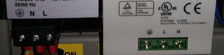
39 User Manual Troubleshooting and Diagnostics QCL-MAN -CT2211-Aerosol-Leak-Detection-System-Rev F October Troubleshooting and Diagnostics The aerosol leak detection system is designed to run unattended and to recover from system issues where possible. This chapter is designed to assist you in the identification and solution of potential problems. If in doubt, contact Cascade Technologies Ltd for clarification on solutions before continuing. 7.1 Warning and error messages There are a number of warning and error messages that the system can generate, which will be displayed in the message box at the bottom of the screen. Table 7-1 Possible problems and solutions Problem Symptom Possible causes Solutions Plots are not updated on the leak detection system Graphs screen. The laser pulse graph and concentration graph are not displayed or do not update on the leak detector Graphs screen. The network connection is not established. The leak detection system network cable must be connected to the network switch in the control console, and the network cable to the PC must be installed into the same switch. Ensure that the indicator lights are flashing on the network switch for both cables. See Figure 7-1. The leak detection system is not powered. See the leak detection systems manual for trouble shooting. Check the LED on the 12V PSU in the control console. See Figure 7-2. Cannot update system settings It is not possible to change any of the parameters, such as output gate position. You are logged in as User. In order to make changes to the settings, you must be logged in as Power User or above. Log in as a Power User or above. The touch screen is not working. Contact the factory. System does not boot up when powered The control system does not power on. The isolation switch on the front of the control system is set to OFF. Turn the isolation switch to the ON position. The circuit breaker on the inside of the control system is tripped. Set the circuit breaker to the ON position. See Figure 7-3. The system was not powered off for long enough. The isolation switch must be off for a minimum of thirty seconds prior to booting the system. Turn the system off. Wait thirty seconds, and then turn the system back on. Troubleshooting and Diagnostics 33

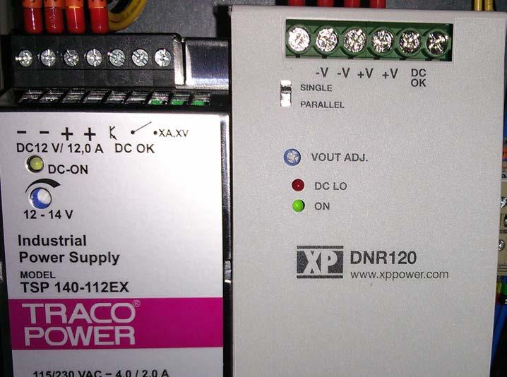
40 Troubleshooting and Diagnostics October 2015 User Manual QCL-MAN-CT2211-Aerosol-Leak-Detection-System-Rev F Figure 7-1 Network status Network status lamps Figure V PSU status 12V PSU status lamp Troubleshooting and Diagnostics 34

41 User Manual Troubleshooting and Diagnostics QCL-MAN -CT2211-Aerosol-Leak-Detection-System-Rev F October 2015 Figure 7-3 Circuit breaker Circuit breaker Troubleshooting and Diagnostics 35
Redefining aerosol leak detection with speed, accuracy & reliability.
 Redefining aerosol leak detection with speed, accuracy & reliability. Cascade Aerosol Micro Leak Detection Systems Achieve unmatched quality and compliance with automated, in-line leak detection. Optimize
Simplex Panel Interface Guide
 Simplex Panel Interface Guide February 2016 SATEON Software Integrations Simplex Panel Interface Guide Issue 1.0, released February 2016 Disclaimer Copyright 2016, Grosvenor Technology. All rights reserved.
Manual# User s Manual. 200E Series. DCU 210E/208E Diesel Engine Control Unit RP 210E Remote Panel
 Manual# 1006494 User s Manual 200E Series DCU 210E/208E Diesel Engine Control Unit RP 210E Remote Panel User's Manual Rev. 1.0 Marine Pro 200E Series ~~~ DCU 210E Diesel Engine Control Unit DCU 208E Diesel
Refrigeration Controller Operator s Manual (HRC) PO Box 6183 Kennewick, WA
 PO Box 6183 Kennewick, WA") Refrigeration Controller Operator s Manual (HRC) PO Box 6183 Kennewick, WA 99336 www.jmcvr.com 1-509-586-9893 Table of Contents TABLE OF FIGURES...1 OVERVIEW OF THE HRC CAPABILITIES...2 INSTALLATION AND
Refrigeration Controller Operator s Manual (HRC) PO Box 6183 Kennewick, WA 99336 www.jmcvr.com 1-509-586-9893 Table of Contents TABLE OF FIGURES...1 OVERVIEW OF THE HRC CAPABILITIES...2 INSTALLATION AND
FIRERAY 5000 range USER GUIDE
 FIRERAY 5000 range USER GUIDE 0044-003-04 IMPORTANT PLEASE NOTE: The beam path MUST be kept clear of obstructions at all times! Failure to comply may result in the Detector initiating a Fire or Fault signal.
Algo-Tec 6500/6600 INTERACTIVE ADDRESSABLE FIRE CONTROL SYSTEM
 Algo-Tec 6500/6600 INTERACTIVE ADDRESSABLE FIRE CONTROL SYSTEM (1-4 LOOPS) USER MANUAL Protec Fire Detection plc, Protec House, Churchill Way, Nelson, Lancashire, BB9 6RT, ENGLAND +44 (0) 1282 717171 www.protec.co.uk
SAFETY MANUAL. Multispectrum IR Flame Detector X3301
 SAFETY MANUAL Multispectrum IR Flame Detector X3301 SAFETY-CERTIFIED MODEL X3301 MULTISPECTRUM INFRARED DETECTOR This manual addresses the specific requirements and recommendations applicable to the proper
Manual# User s Manual. 200 Series. DCU 210/208 Diesel Engine Control Unit RP 210 Remote Panel
 Manual# 1100334 User s Manual 200 Series DCU 210/208 Diesel Engine Control Unit RP 210 Remote Panel Rev. March 2012 User's Manual for the Marine Pro 200 Series ~~~ DCU 210 Diesel Engine Control Unit DCU
Flopurge TS. Operation Manual
 Flopurge TS Operation Manual Part Number 079-0204 Spectron Gas Control Systems United Kingdom Unit 4, Herald Court, University of Warwick Science Park, Coventry, CV4 7EZ +44 (0)24 7641 6234 sales@spectron-gcs.com
Protégé Eclipse LED Keypad User Manual PRT-KLES
 Protégé Eclipse LED Keypad User Manual PRT-KLES The specifications and descriptions of products and services contained in this manual were correct at the time of printing. Integrated Control Technology
SAFETY MANUAL. X2200 UV, X9800 IR, X5200 UVIR SIL 2 Certified Flame Detectors
 SAFETY MANUAL X2200 UV, X9800 IR, X5200 UVIR SIL 2 Certified Flame Detectors SAFETY-CERTIFIED Flame DETECTORs This manual addresses the specific requirements and recommendations applicable to the proper
6100 SINGLE LOOP DIGITAL ADDRESSABLE FIRE ALARM CONTROL PANEL
 6100 SINGLE LOOP DIGITAL ADDRESSABLE FIRE ALARM CONTROL PANEL USER MANUAL Protec Fire Detection plc, Protec House, Churchill Way, Nelson, Lancashire, BB9 6RT. Telephone: +44 (0) 1282 717171 Fax: +44 (0)
Flostop TS D7E and A8E. Operation Manual
 Flostop TS D7E and A8E Operation Manual United Kingdom Spectron Gas Control Systems Ltd, Unit 4, ATU1, University of Warwick science Park, Coventry, +44 (0) 24 7641 6234 sales@spectron-gcs.com Germany
Operations Manual TS400. Test Station for G450/G460 Gas Detector
 TS400 Test Station for G450/G460 Gas Detector Operations Manual 1194 Oak Valley Dr, Ste 20, Ann Arbor MI 48108 USA (800) 959-0329 (734) 769-0573 www.goodforgas.com GfG Products for Increased Safety Congratulations
User s Manual. TIGER S EYE E-Series Mark V Jockey. TIGERFLOW Systems, Inc Mint Way Dallas, Texas
 User s Manual TIGER S EYE E-Series Mark V Jockey TIGERFLOW Systems, Inc. 4034 Mint Way Dallas, Texas 75237 214-337-8780 www.tigerflow.com TABLE OF CONTENTS Introduction... 4 Sequence of Operation... 5
E N G L I S H FIRE ALARM ASPIRATION SENSING TECHNOLOGY QUICK INSTALLATION GUIDE STAND-ALONE FAAST LT MODELS FL0111E FL0112E FL0122E. 367 mm.
 E N G L I S H FIRE ALARM ASPIRATION SENSING TECHNOLOGY QUICK INSTALLATION GUIDE STAND-ALONE FAAST LT MODELS FL0E FL0E FL0E mm mm 0 mm DESCRIPTION The LT FL0 Series is part of the Fire Alarm Aspiration
PROPOINT PLUS ASPIRATING SMOKE DETECTION SYSTEM
 PROPOINT PLUS ASPIRATING SMOKE DETECTION SYSTEM USER MANUAL Protec Fire Detection plc, Protec House, Churchill Way, Nelson, Lancashire, BB9 6RT, ENGLAND +44 (0) 1282 717171 www.protec.co.uk sales@protec.co.uk
ProStar 325 UV-Vis Detector
 Varian, Inc. 2700 Mitchell Drive Walnut Creek, CA 94598-1675/USA Star Chromatography Workstation Version 6 ProStar 325 UV-Vis Detector Control Software Varian, Inc. 2004 Printed in U.S.A. 03-914732-01:Rev.
Design Manual Installation Operation Maintenance
 Design Manual Installation Operation Maintenance Model FT194 UV/IR Portable Flame Detector Test Lamp 23282 Mill Creek Drive, Suite 215 Laguna Hills, CA 92653 USA +1.949.583.1857 Phone +1.949.340.3343 Fax
Instruction manual MTL process alarm equipment. October 2016 CSM 725B rev 2 MTL RTK 725B. Configuration Software Manual
 Instruction manual MTL process alarm equipment October 2016 CSM 725B rev 2 MTL RTK 725B Configuration Software Manual SECTION 1 - INTRODUCTION... 5 Basic Requirements... 5 SECTION 2 - SOFTWARE INSTALLATION...
Dryer Controller M720
 User Manual Dryer Controller M720 Hardware version 2.00 Software version 2.00 Manual M720 Dryer controller Page 1 of 60 Document history Preliminary version: - Created in April, 2009 Hardware Version 2.00,
LaserRobot. Controller s User Manual. Hotline: Add: 1500xinfei Road No.72, Shanghai, China
 LaserRobot Controller s User Manual Hotline: +86 400-670-1510 Email: sales@empower.cn Add: 1500xinfei Road No.72, Shanghai, China Version: V1.0 Date: 2017/12/22 Historical Version: Historical Version Date
HIGH EFFICIENCY FIRETUBE CONDENSING GAS BOILER
 This manual must be left with owner and should be hung on or adjacent to the boiler for reference. US HIGH EFFICIENCY FIRETUBE CONDENSING GAS BOILER MODELS CHS-85 through CHS-399 APPENDIX A CONTROLLER
Covidien Articulating Absorba Tack Foil Pouch Leak Tester Owner s Manual IPE SN Rev 1
 Covidien Articulating Absorba Tack Foil Pouch Leak Tester Owner s Manual IPE SN 12497 Rev 1 MANUFACTURER: INNOVATIVE PRODUCTS & EQUIPMENT, INC. 5 PROGRESS AVE TYNGSBORO, MASSACHUSETTS 01879 U.S.A Revision
SAFETY MANUAL. PointWatch Eclipse Infrared Hydrocarbon Gas Detector Safety Certified Model PIRECL
 SAFETY MANUAL PointWatch Eclipse Infrared Hydrocarbon Gas Detector SIL 2 Certified Model PIRECL Safety Certified Model PIRECL PointWatch Eclipse IR Gas Detector This manual addresses the specific requirements
OPERATING MANUAL Enertronic Control System 2
 OPERATING MANUAL Enertronic Control System 2 The integrated control system for Lennox chillers in the Ecologic range Manufacturer: Lennox Benelux B.V. Postbus 1028, 3860 BA NIJKERK Watergoorweg 87, 3861
TS400. Operating Manual. Test Station for Microtector II Series (G450/G460)
") Operating Manual TS400 Test Station for Microtector II Series (G450/G460) GfG GESELLSCHAFT FÜR GERÄTEBAU MBH KLÖNNESTRASSE 99 44143 DORTMUND, Germany TEL. +49 / (0)2 31 / 5 64 00 0 FAX +49 / (0)2 31 /
Operating Manual TS400 Test Station for Microtector II Series (G450/G460) GfG GESELLSCHAFT FÜR GERÄTEBAU MBH KLÖNNESTRASSE 99 44143 DORTMUND, Germany TEL. +49 / (0)2 31 / 5 64 00 0 FAX +49 / (0)2 31 /
Advisor Advanced Mobile Application User Manual
 Advisor Advanced Mobile Application User Manual Content Warnings and Disclaimers 2 Advanced Mobile 2 Contact information 2 Description 2 Screen navigation 4 Gestures 4 Menu 4 Help navigation 4 Login 5
1. Quick start-up guide
 1. Quick start-up guide This quick guide leads the way to install, start-up and configure necessary parameters in the normal cases. 1. PREPARING INSTALLATION Install fiber optic cable inside conduit. This
Avigilon Control Center System Integration Guide
 Avigilon Control Center System Integration Guide with Velocity INT-HIRSCH-A-Rev3 Copyright 2013 Avigilon. All rights reserved. No copying, distribution, publication, modification, or incorporation of this
Centaur TM II Cube Slave Alarm Signalling Equipment INSTALLATION GUIDE
 Centaur TM II Cube Slave Alarm Signalling Equipment INSTALLATION GUIDE General Description This guide provides a summary for installing and configuring the Centaur TM Cube Slave Alarm Signalling Equipment
Operating & Maintenance Manual. Alert-4 Ethernet LCD Master Alarm
 Operating & Maintenance Manual Alert-4 Ethernet LCD Master Alarm w w w. a m i c o. c o m Contents User Responsibility 4 Introduction 4 Features 5 Description of the Alarm 5 Shipment Details 5 The Alarm
ZERIO PLUS EDA-Z5008, Z5020 & Z5100
 ZERIO PLUS EDA-Z5008, Z5020 & Z5100 USER MANUAL Revision 1.00 EDA-Z5008, Z5020 & Z5100 User Manual 0359 Electro Detectors Limited Electro House Edinburgh Way Harlow, Essex CM20 2EG, UK 14 0359 CPR 00226
Security System. User Guide for the LED Command Center
 Security System User Guide for the LED Command Center National Security Systems Inc (800)457-1999 MY SECURITY COMPANY IS: CALL BEFORE TEST: THIS SECURITY SYSTEM IS CONNECTED TO TELEPHONE NUMBER: THE SECURITY
This is to certify that the optical output of the: SENSORNET LR-DTS Temperature Sensing System: (Variants Mark 1, Mark 2a and Mark 2b)
") Optical Services Ltd. This is to certify that the optical output of the: SENSORNET LR-DTS Temperature Sensing System: (Variants Mark 1, Mark 2a and Mark 2b) Meets the requirements stated in IEC 60825-1:2001
Optical Services Ltd. This is to certify that the optical output of the: SENSORNET LR-DTS Temperature Sensing System: (Variants Mark 1, Mark 2a and Mark 2b) Meets the requirements stated in IEC 60825-1:2001
CONTROL PANEL INTERFACE ACTIVATE THE GENERATOR DISPLAY INTERFACE MENUS. Control Panel USING THE AUTO/OFF/MANUAL SWITCH
 CONTROL PANEL INTERFACE USING THE AUTO/OFF/MANUAL SWITCH With the switch set to AUTO, the engine may crank and start at any time without warning. Such automatic starting occurs when utility power source
HD IR Vari-focal Dome Network Camera. Quick Start Guide. Version 1.0.0
 HD IR Vari-focal Dome Network Camera Quick Start Guide Version 1.0.0 Welcome Thank you for purchasing our network camera! This quick start guide is designed to be a reference tool for your system. Please
Operations Manual TS400. Test Station for G450/G460 Gas Detector
 TS400 Test Station for G450/G460 Gas Detector Operations Manual 1194 Oak Valley Dr, Ste 20, Ann Arbor MI 48108 USA (800) 959-0329 (734) 769-0573 www.gfg-inc.com GfG Products for Increased Safety Congratulations
ModSync Sequencing System Installation & Operation Manual. For use with Fulton Steam Boilers.
 ModSync Sequencing System Installation & Operation Manual For use with Fulton Steam Boilers. Revision 3.0 8/21/2008 - 2 - Table of Contents Introduction Page 4 Features Page 4 Sequence of Operation Page
SAFETY CERTIFIED MODEL FP-700 COMBUSTIBLE GAS DETECTOR
 SAFETY MANUAL SIL 2 Certified Model FP-700 Combustible Hydrocarbon Gas Sensor Version 2.0 1 SAFETY CERTIFIED MODEL FP-700 COMBUSTIBLE GAS DETECTOR This manual addresses the specific requirements and recommendations
IMPORTANT. PLEASE NOTE: The infrared beam path MUST be kept clear of obstructions at all times!
 USER GUIDE English IMPORTANT PLEASE NOTE: The infrared beam path MUST be kept clear of obstructions at all times! Failure to comply may result in the Detector initiating a Fire or Fault signal. Contents
DEEP SEA ELECTRONICS PLC DSE94xx Battery Charger Series Configuration Suite PC Software Manual
 DEEP SEA ELECTRONICS PLC DSE94xx Battery Charger Series Configuration Suite PC Software Manual Document Number: 057-159 Author: Fady Atallah DSE94xx Configuration Suite PC Software Manual ISSUE 15 DSE94xx
Siemens aspirating smoke detector (ASD) for the addressed FDnet/C-NET detector line or for standalone operation
 for the addressed FDnet/C-NET detector line or for standalone operation") Sinteso Cerberus PRO FDA241, FDA221 ASD Aspirating smoke detector Siemens aspirating smoke detector (ASD) for the addressed FDnet/C-NET detector line or for standalone operation Patented technology Early
Sinteso Cerberus PRO FDA241, FDA221 ASD Aspirating smoke detector Siemens aspirating smoke detector (ASD) for the addressed FDnet/C-NET detector line or for standalone operation Patented technology Early
REVO JOB INSTALLATION AREA. REVO Job SELECTION TABLE MAIN FEATURES OF THE PRODUCT PROFESSIONAL. CE marking. Automatic filter cleaning
 REVO JOB Revo Job is the new Sistem Air vacuum unit designed for intensive use in tertiary and professional areas. The main features of this product are simplicity, reliability and a great vacuum power.
[ [ ADMIN PANEL USER GUIDE
 [ [ ADMIN PANEL USER GUIDE ADMIN PANEL USER GUIDE 2 Contents Logging In & Systems Overview 3 System Details 5 Analytics 6 View Alarms 8 Manage Alarms 9 Create Alarms 10 Device Reporting Alarm 11 Monthly
DDS-SSENSOR - INSTALLATION MANUAL. Installation Manual DDS-S SENSOR
 Installation Manual DDS-S SENSOR 1 TRANSLATED DOCUMENT This manual has been compiled according to standard UNE-EN-ISO 12100. INSTALLATION MANUAL DDS-S SENSOR Read thoroughly all of these instructions before
Alarm Monitoring and Management
 CHAPTER 10 This chapter describes Cisco Transport Controller (CTC) alarm management. To troubleshoot specific alarms, refer to the Cisco ONS 15310-MA SDH Troubleshooting Guide. Chapter topics include:
Installation and Operation Manual
 SENTRY Protect Plus QUADPLEX PANEL Installation and Operation Manual For Hardwired Pumps Environment e Corporation Table of Contents 1 Overview...3 2 Sentry Protect Plus Quadplex Menu Flowchart...4 3 Wiring
IMR 5000 IMR 400. CEMS Operating Manual IMR USA S/N: Sample IMR Sensors Inside IMR 400. Gas Dryer Inside. IMR Environmental Equipment Inc.
 CEMS Operating Manual IMR USA S/N: Sample IMR 5000 IMR 400 IMR 400 IMR 5000 Measure MESURE PURGE Purge CALIBRATE Calibrate OFF OFF RESET Measure ON ON Calibrate RESET PUMP Gas Dryer Inside PUMP Sensors
C-Bus Four Channel General Input Unit Installation Instructions
 C-Bus Four Channel General Input Unit Installation Instructions 5504GI Series REGISTERED DESIGN REGISTERED PATENT Table of Contents Section...Page 1.0 Product Range... 3 2.0 Description... 3 3.0 Capabilities...
Diagnostics and Monitoring System WEB Tool 2. User Manual
 Diagnostics and Monitoring System 2 (Translation of the original documentation) User Manual S/N: Valid from: 01.05.2012 Rev.: 2.0 2 Rev. 1.... 1 1.1 General information... 1 1.1.1 Equipment... 1 1.1.2
Added password for IP setup page : Password must be in IP format!
 NETWORK POWER MONITOR Release : 21 August 2014 Hardware Version : Version 7 Firmware version 1.00 PC Application Software : Version (latest)...2 Added password for IP setup page : Password must be in IP
APC BC300 Series 40kW 208/450/480V User Guide
 APC BC300 Series 40kW 208/450/480V User Guide Copyright 2002 APC Denmark ApS This manual is subject to change without notice and does not represent a commitment on the part of the vendor Thank You Thank
725B Configuration Software Manual
 725B Configuration Software Manual REV DATED DESCRIPTION AUTHOR APPROVED 0 09-03-10 First Issue P.Cartmell Page 1 of 80 SECTION 1 - SOFTWARE INSTALLATION... 5 725B ConfigurationSoftware Installation...
THX-DL Data Logger USER & INSTALLATION MANUAL V
 THX-DL Data Logger USER & INSTALLATION MANUAL V1.2012 www.thermomax-refrigeration.com Contents PRESENTATION Summary of Features 2 INSTALLATION Safety Precautions 4 THX Unit 4 Sensors 4 Alarm Relay 4 Power
Ion Gateway Cellular Gateway and Wireless Sensors
 Page 1 of 9 Account & Network Setup If this is your first time using the Ion Gateway online system site you will need to create a new account. If you have already created an account you can skip to the
Operator's Handbook. Interactive Fire Alarm System Release 3. Information Panel, BV-320. Protecting life, environment and property...
 Interactive Fire Alarm System Release 3 Operator's Handbook Information Panel, BV-320 Protecting life, environment and property... ASAFE-IN/FE Rev. A, 010531 COPYRIGHT This publication, or parts thereof,
CIRRUS PRO. User Manual and Responsibilities ASPIRATING FIRE DETECTOR
 CIRRUS PRO ASPIRATING FIRE DETECTOR User Manual and Responsibilities Protec Fire Detection (Export) Ltd, Protec House, Churchill Way, Nelson, Lancashire. BB9 6RT. Telephone: +44 (0) 1282 717171 Fax: +44
FlameGard 5 MSIR HART
 FlameGard 5 MSIR HART Multi-Spectral Infrared Flame Detector HART Communication with the FlameGard 5 Multi-spectral Infrared Detector The information and technical data disclosed in this document may be
Universal Monitoring System. Model IMEC8A. User Manual Version 1.10 Software version 2.3.1
 Unit 7/8, Heathrow Causeway Estate, Ariel Way, Hounslow Middlesex, TW4 6JW +44 (0) 208 6302270 www.cpcuk.co.uk Universal Monitoring System Model IMEC8A User Manual Version 1.10 Software version 2.3.1-1
Alarm Client. Installation and User Guide. NEC NEC Corporation. May 2009 NDA-30364, Revision 9
 Alarm Client Installation and User Guide NEC NEC Corporation May 2009 NDA-30364, Revision 9 Liability Disclaimer NEC Corporation reserves the right to change the specifications, functions, or features,
DOCUMENTATION IPS640
 DOCUMENTATION IPS640 TECHNICAL AND APPLICATION DESCRIPTION Authors: Nebojša Božič, Peter Hauner Last modification: 2017-01-25 2001-2017 Apricum d.o.o. Mažuranićeva 4, 21312 Podstrana, Hrvatska Details,
DOCUMENTATION IPS640
 DOCUMENTATION IPS640 TECHNICAL AND APPLICATION DESCRIPTION Authors: Nebojša Božič, Peter Hauner Last modification: 2018-07-06 2001-2018 Apricum d.o.o. Mažuranićeva 4, 21312 Podstrana, Hrvatska Details,
FlameGard 5 UV/IR HART
 FlameGard 5 UV/IR HART HART Communication Manual The information and technical data disclosed in this document may be used and disseminated only for the purposes and to the extent specifically authorized
RMS-I-DE-01 Smoke Detector
 RMS-I-DE-01 Smoke Detector 2012 CONTEG, spol. s r.o. All rights reserved. No part of this publication may be used, reproduced, photocopied, transmitted or stored in any retrieval system of any nature,
OSA 3. Level alarm for oil separator. Afriso Ema AB. Kilvägen 2 SE Arlöv Sweden T +46-(0) F +46-(0)
 F +46-(0)") Level alarm for oil separator CONTENTS: Functional description... 2 Component parts... 3 Spare parts... 5 Safety regulations... 6 Checklist... 7 Installation... 8 Commissioning... 11 Operation... 14 Maintenance...
Level alarm for oil separator CONTENTS: Functional description... 2 Component parts... 3 Spare parts... 5 Safety regulations... 6 Checklist... 7 Installation... 8 Commissioning... 11 Operation... 14 Maintenance...
User instructions DHP-AT
 User instructions DHP-AT VUGFC202 If these instructions are not followed during installation and service, Danfoss A/S liability according to the applicable warranty is not binding. Danfoss A/S retains
DELOMATIC 400, DM-400 HYDRO
 Delomatic 400 HYDRO controller OPERATOR S MANUAL DELOMATIC 400, DM-400 HYDRO Functional description User interface Log books Alarm handling Document no.: 4189340880A SW version 1.0 or later Table of contents
ECO N DATE DESCRIPTION OF CHANGE CHG
 Model Number: M21E-24-DIN Description: The product is a loop powered device which controls an unsupervised dual pole output channel suitable to manage 24VAC loads. The M21E-24-DIN is micro-controller operated,
Original operating instructions Safety switch with guard locking AC901S AC902S
 Original operating instructions Safety switch with guard locking AC901S AC902S 7390914/03 01/2017 Contents 1 Preliminary note...4 1.1 Explanation of symbols...4 2 Safety instructions...4 3 Items supplied...5
Setting the New Standard in Chiller Technology ±0.1 C ZEROPOINT CHILLER SERIES
 L i t r o n T o t a l L a s e r C a p a b i l i t y Setting the New Standard in Chiller Technology ±0. C ZEROPOINT CHILLER SERIES Litron s Zeropoint Series Setting the New Standard in Advanced Chiller
AquaLynx 200 ADX. Monitoring and Control System. Background. Operation
 AquaLynx 200 ADX Monitoring and Control System The RODI Systems AquaLynx 200 ADX is a unique monitoring system for water treatment applications. The AquaLynx 200 ADX offers a dependable yet affordable
G4 Pulsed Fiber Laser
 G4 Pulsed Fiber Laser OEM Safety and System Integration Manual Module types C1 and C2 Module type C1 - fitted with IBeam1 delivery optic Module type C2 - fitted with IBeam2 delivery optic 1 1 Preface Definition
Operation & Maintenance Manual
 Operation & Maintenance Manual for Model 2100 Fire+Smoke systems from Smoke Guard, Inc. 287 N. Maple Grove - Boise, ID 83704 Phone: (800) 574-0330 Fax: (208) 639-7851 E-Mail: info@smokeguard.com Website:
PACSystems* RX3i. Thermocouple Input Module, 12 Channels, IC695ALG412. GFK-2578B October 2011
 October 2011 PACSystems* RX3i Thermocouple Input Module, 12 Channels, IC695ALG412 The PACSystems * Thermocouple Input module IC695ALG412 provides twelve isolated differential thermocouple input channels.
ISO Acceptance tests for Nd:YAG laser beam welding machines Machines with optical fibre delivery Laser assembly
 INTERNATIONAL STANDARD ISO 22827-1 First edition 2005-10-15 Acceptance tests for Nd:YAG laser beam welding machines Machines with optical fibre delivery Part 1: Laser assembly Essais de réception pour
GigaCore 12. Gigabit Ethernet Switch for the entertainment industry. Quick Start Guide. V2.1.0 Rev5. English
 GigaCore 12 Gigabit Ethernet Switch for the entertainment industry Quick Start Guide V2.1.0 Rev5 English Table of Content Safety Instructions 3 Compliance information 4 Warranty information 5 Registration
Series DCT1000DC Dust Collector Timer Controller Specifications Installation and Operating Instructions
 Series DCT1000DC Dust Collector Timer Controller Specifications Installation and Operating Instructions Bulletin E-97DC Thank you for purchasing the Dwyer DCT1000DC Dust Collector Timer Controller. You
DIESEL ENGINE CONTROL UNIT DCU USER S MANUAL - N-2000 Lillestrøm, Norway Tel: (+47) Fax: (+47)
 Fax: (+47)") DIESEL ENGINE CONTROL UNIT DCU 205 - USER S MANUAL - N-2000 Lillestrøm, Norway Tel: (+47) 64 84 52 00 Fax: (+47) 64 84 52 12 office@auto-maskin.no - 1 - TABLE OF CONTENTS 1. INTRODUCTION TO THE DCU 205...4
DIESEL ENGINE CONTROL UNIT DCU 205 - USER S MANUAL - N-2000 Lillestrøm, Norway Tel: (+47) 64 84 52 00 Fax: (+47) 64 84 52 12 office@auto-maskin.no - 1 - TABLE OF CONTENTS 1. INTRODUCTION TO THE DCU 205...4
3500 CONVENTIONAL FIRE ALARM CONTROL PANEL
 3500 CONVENTIONAL FIRE ALARM CONTROL PANEL USER MANUAL Protec Fire Detection PLC, Protec House, Churchill Way, Nelson, Lancashire, BB9 6RT. Telephone: +44 (0) 1282 717171 Fax: +44 (0) 1282 717273 Web:
Operation Manual Fighter ProVision Software. Version: 0.0 Revision: 1
 Operation Manual Fighter ProVision Software Version: 0.0 Revision: 1 TABLE OF CONTENTS 1. Introduction 5 2. Software Installation 5 3. PC Users 6 3.1 Introduction 6 3.2 Default Code 6 3.3 Edit PC User
Module Features are-configurable, no module jumpers to set
 December 2011 PACSystems* RX3i Isolated Thermocouple Input Module, 6 Channels, IC695ALG306 Isolated Thermocouple Input Module, 12 Channels, IC695ALG312 Isolated Thermocouple Input module IC695ALG306 provides
2000 Series. Program Entry Guide. Control Panels
 2000 Series EN Program Entry Guide Control Panels 2000 Series Program Entry Guide About This Manual EN 2 About This Manual This guide describes the programming parameters available to the 2000 Series Control
TraceNet ECM Series Control System
 TraceNet ECM Series Control System ECM Operating Guide Thermon Manufacturing Company TraceNet is a registered trademark of Thermon Manufacturing Company. ECM Operating Guide 2014, 2015 Thermon Manufacturing
Part 3 Troubleshooting
 Part Troubleshooting What is in this part? This part contains the following chapters: Chapter See page Troubleshooting 2 Error Codes: Hydro-box 7 Error Codes: Outdoor Units Error Codes: System Malfunctions
User Manual. Dryer Controller M720
 User Manual Dryer Controller M720 Hardware version 1.00 Software version 1.00 Preliminary version Manual M720 Dryer controller Page 1 of 42 Document history Preliminary version: - Created in April, 2009
SCAN200E USER S MANUAL
 SCAN200E USER S MANUAL Code No. 2071 1052 rev. 1.4 Code No. 2071 1052 Rev. 1.4 Page 2/16 SCAN200E User s Manual Foreword This manual is for SCAN200E Controller running software version 2.03 or later. We
MPT Electric Fire Pump Controller
 Setup and Operating Instructions MPT Electric Fire Pump Controller This manual provides general information, installation, operation, maintenance, and system setup information for Metron MPT Electric Fire
Tri-Stack Smart System
 Tri-Stack Smart System TM Notes & Warnings - The protection provided by this equipment may be impaired if it is not used in the manner specified herein. - Ensure all wiring meets applicable national and
Thermo Scientific Aerosol Monitor FHT 58 S Technical Specification ZT-221E
 Thermo Scientific Aerosol Monitor FHT 58 S Technical Specification ZT-221E Thermo Fisher Scientific Messtechnik GmbH Frauenauracher Straße 96 91056 Erlangen Germany www.thermo.com info.rmp.erlangen@thermofisher.com
READ AND SAVE THESE INSTRUCTIONS
 XXXXXXX-0 EN 1904 READ AND SAVE THESE INSTRUCTIONS BASIC-PLC CONTROLLER MANUAL For all Condair desiccant dryer with equipped with Basic- PLC valid from version: PLC-35/PLC-45 18.04.03 Dehumidification
CELLTROL II BIOREACTOR CONTROL SYSTEM OPERATIONS MANUAL
 Operation Manual Celltrol II Bioreactor Control System Page 1 of 33 Table of Contents 1) Introduction... 3 1.1) Scope of Document... 3 1.2) Control System Overview... 3 1.3) Introduction to Celltrol II...
RMS/RPX Reader. User Manual
 RMS/RPX Reader User Manual Copyright Disclaimer Trademarks and patents Intended use FCC compliance Copyright 2005, GE Security Inc. All rights reserved. This document may not be copied or otherwise reproduced,
Memcom Emergency Telephone
 Memcom Emergency Telephone Installation Guide Ref No. 450 900 (GB) Version 2 + + Simple wiring for quick installation + + Integrated LCD display shows you what you have programmed + + All code based programming
Apollo Intelligent Auto Aligning Beam Detector. User Guide
 Apollo Intelligent Auto Aligning Beam Detector User Guide EN 1. General Information 50cm 50cm 8-100m Ensure clear line of sight from Detector to Reflector Mount on solid surfaces (structural wall or girder)
Operating principle. Quinto
 Operating principle Quinto All rights reserved. No part of this document may be copied and/or published by means of printing, photocopying, microfilming or by any other means whatsoever without the prior
OTFAMU Fresh Air Make Up System For Chilled Water OPERATOR S MANUAL. Technicold Marine Systems
 OTFAMU Fresh Air Make Up System For Chilled Water OPERATOR S MANUAL Technicold Marine Systems www.technicold.com Technicold by Northern Lights 1419 W. Newport Center Drive Deerfield Beach, FL 33442 Tel:
Dryer Master DM510 Commissioning Guide
 COMMISSIONING GUIDE Dryer Master DM510 Dryer Moisture Systems Inc. 640 Superior Drive Waterloo, Ontario Phone 519.725.4700 Fax 519.885.4300 USA & Canada Toll Free 1-888-318-0009 E-mail: info@dryermaster.com
LZR -I30. max. detection range of 30 ft x 30 ft LASER SCANNERS FOR INDUSTRIAL DOORS LZR-I Page 1 of 12
 EN LZR -I30 LASER SCANNERS FOR INDUSTRIAL DOORS max. detection range of 30 ft x 30 ft 75.5667.07 LZR-I30 0509 Page of SAFETY The device contains IR and visible laser diodes. IR laser: wavelength 905nm;
Manual# User s Manual. DCU 410/408 Engine Control Unit RP 410 Remote Panel FW 2.3
 Manual# 1100268 User s Manual DCU 410/408 Engine Control Unit RP 410 Remote Panel FW 2.3 Table of Content GENERAL INFORMATION... 3 ABOUT THIS MANUAL... 3 400 SERIES OVERVIEW... 3 Available Modules...