Operation Manual. smart-house Controller BH8-CTRLZx
|
|
|
- Thomas King
- 6 years ago
- Views:
Transcription


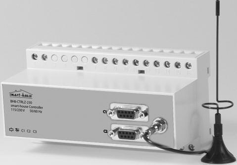
1 Operation Manual smart-house Controller BH8-CTRLZx October 2007
2 smart-house controller BH8-CTRLZx Table of Contents 1. Introduction Start-up Hardware requirements Installation Start-up of program Functions in the main window File menu Edit menu Tools menu Options menu Help menu Configuration of channel functions Basic Setup Objects General Standard objects Blank / Indicator Push-button Toggle switch Timer/Recycler Real-time clock / Night setback Master function Guide Light Light Synch Multigate Thermostat Special objects Analog sensors Motion detector Dimmer functions Light functions Temperature Control Wireless Base Alarm functions Overview General features ISA Alarm Smoke Alarm Intruder Alarm Water Alarm Common Siren Roller blind control Decentralized roller blind up-down function Roller blind master Counter and Multiplexer 74 is not part of the smart-house system and vill not be described in this manual Carlo Gavazzi Industri A/S. All rights reserved
3 smart-house controller BH8-CTRLZx 3. Logic Setup Introduction The dialog - logic functions Setup Application Setups and Functions Inversion and Edge Triggering Using the on-board I/O s Internal processing of the logic setups Notes and Documentation Input definitions Communication Ports General Protocol COM COM RS Setup of Communication Ports GSM Modem functions SMS Setup Event-based SMS messages SMS Control commands and Requests for smart-house data Radio Modem Functions 86 is not part of the smart-house system and vill not be described in this manual Appendix A 87 Appendix B - ModBus Functions 88 Appendix C - RS485 Communications Carlo Gavazzi Industri A/S. All rights reserved 3

4 smart-house controller BH8-CTRLZx 1. Introduction 1.1. Start-up The configuration tool has been designed for configuration of the smart-house controller BH8-CTRLZx. All functions in the smart-house controller are represented by graphic symbols, and all function related parameters and comments are setup locally in the PC, and then transferred to the smart-house controller through RS232. Likewise, data from the smart-house controller can be uploaded and modified. The smart-house controller firmware and configuration tool are subject to changes, as new functions are added continuously Hardware requirements The program operates under Windows 95/98/2000/xp and NT and requires at least: 400Mhz Pentium II processor with 32 Mbytes Ram or higher A free serial port (Com1 or Com2) 10 Mbytes hard disk for installation Screen resolution of 800 x 600 pixels, 256 colours or higher Mouse or other pointing tool desirable, but not necessary Installation Insert the CD rom and run the program Setup.exe. This will guide you through the installation process. After installation, the program can be started by clicking the icon on your desktop Start-up of program When the configuration tool is started, two windows will open: To the left, the main window showing the 128 addresses available in smart-house and the menus. To the right, the properties window, which for each function shows the parameters related to the selected functions. A third window may appear, which also contanis configuration entries, or functions for maintenance and test Carlo Gavazzi Industri A/S. All rights reserved

5 smart-house controller BH8-CTRLZx 1.2. Functions in the main window File menu The file menu contains the usual functions: Menu Item: New: Open: Save: Save As: Write smart-house controller: Read smart-house controller: Export configuration: Print: Input definitions Exit: Explanation Start from the beginning with default data Open existing file Save file Save file under new name Download the present configuration file to the smart-house controller Read the configuration file from the smart-house controller Is not part of the smart-house concept and will not be described in this manual The following options are available: Print-out of: Address Listing Master Channels & multigate Real time Channels Logic Settings SMS Setup External References Exit program 2007 Carlo Gavazzi Industri A/S. All rights reserved 5

6 smart-house controller BH8-CTRLZx Edit menu Menu Item: Basic Setup: Logic Setup: Holiday Setup: SMS Setup Counter and Mux analog Setup: Communication Setup: Analink Log Set-up Mux Counters Log Set-up Mux Analog Log Set-up Input definitions Explanation: Basic setup of the smart-house controller Configuration of logic functions Setup of holiday period. The holiday setup is active when the current date falls within any of the set time intervals. Basic setup of the SMS messaging functions facilitated by the built-in GSM modem. Is not part of the smart-house concept and will not be described in this manual Configuration of the communication functions available for the two RS 232 ports and the RS485 port of the smart-house controller. Is not part of the smart-house concept and will not be described in this manual Is not part of the smart-house concept and will not be described in this manual Is not part of the smart-house concept and will not be described in this manual Entry and management of transmitters and their respective addressing Carlo Gavazzi Industri A/S. All rights reserved

7 smart-house controller BH8-CTRLZx Options menu Menu Item: Language: Explanation: Select between available languages. By using the Select new menu, other languages can be chosen to appear in the language menu. Serial port: Selection of serial communication ports from Com 1 to Com 10, for connection of the smart-house controller Tools menu 2007 Carlo Gavazzi Industri A/S. All rights reserved 7

8 smart-house controller BH8-CTRLZx controller firmware: In this menu it is possible to download a new firmware file to the controller. New firmware files are typically made available when new features are added to the controller. Three steps need to be carried out: 1. Browse to select the desired firmware file. 2. Activate the Download button and follow the emerging dialog-boxes. 3. Activate Close button when done. For firmware version 2,0 and onward, see part : Using the on-board I/Os Carlo Gavazzi Industri A/S. All rights reserved

9 smart-house controller BH8-CTRLZx BGT-TEST-SP Test Tool: These tools are used to display the immediate digital status on the smart-house channels. When enabled, control of the smart-house channels is possible as well. This tool provides a good overview of the activity on the smart-house bus and is particularly good when testing the application On-Line Tool Is not part of the smart-house concept and will not be described in this manual Carlo Gavazzi Industri A/S. All rights reserved 9


10 Help menu Menu Item: Explanation: General information: You can call the Help menu at any time by pressing F1. About program: Shows the opening screen Carlo Gavazzi Industri A/S. All rights reserved

11 Configuration of channel functions When the basic settings have been made under Basic Setup, the functions of the remaining channels to be used are defined as follows: Activate one of the channels, then click on the right mouse button for pop-up menu. Click on the desired channel function with the left mouse button. The channel is thereby assigned a symbol indicating the selected channel function. Click on the symbol with the left mouse button, and the parameters which can be set for that particular channel function can be viewed in the properties window. The arrow keys can also be used to select channel function in the pop-up menu. Furthermore, channel function can be selected by clicking on different letters. To see how to select functions by clicking on letters, select the General information menu under Help. Tool tip When the cursor is positioned on an address button, a so-called "ToolTip" appears. The ToolTip indicates the address function, and the user-defined description. Two "!!" in front of the tool-tip indicates that the adress also is controlled by a logic function Carlo Gavazzi Industri A/S. All rights reserved 11

12 1.3. Basic Setup General description The text window is for entering general information, eg name of user, date of configuration, reference to documentation, etc. No. of adresses For selection of the number of channels desired in the system. The minimum is 16, the maximum is 128 in one smart-house network. Restore Channel Status upon Power-up When this function is selected, the smart-house controller will memorize the channel status on toggle channels and real-time channels in case of a loss of power. The smart-house controller will then restore the output status on these channels when the power comes back. The option can not be selected, unless the controller is connected to the PC. Channel restore Interval (1/10 Seconds) In order to reduce the total in-rush current when using the "Restore Channel Status upon Power-up" function, it is possible to define a delay between the activations of outputs. The delay is entered in 1/10 Seconds. Long Activation time Set-up the time, for how long a 'Long activation' must last, before an activation takes place. Some channel objects, are able to be activated by a long activation from another address. Eg. B2 is a Masterfunction, which reacts on a long activation of B1. B1 may be a toggle switch for normal on/off. Now by holding the B1 for the Long activation time, the Masterfunction on B2 activates, this gives B1 two functions, and saves one push-button Carlo Gavazzi Industri A/S. All rights reserved
13 Enable automatic update of realtime status upon Config-download and System power-up If this box is checked, the controller will automatically set the correct status for realtime channels according to the switch-time settings, provided that the actual Day of the week matches the internal Day of the week of the controller. Also, the controller will only scan the switch times (ON or OFF) for that same day. Enable Automatic Daylight saving. Central European Time standard If this box is checked, the controller will automatically change the time settings 2 times per year according to the European standard for daylight savings. Enable RTC Powerline Autocalibration Selecting Auto-calibrate, will enable the internal Realtime clock to adjust its internal calibration against the Mains-supply frequency. In most countries, the Mains-supply frequency is very accurate, and in that case an improved accuracy on the Realtime clock can be achieved. Syncronize Time to PC date and Time If this button is activated when the controller is connected to the PC, then the PC date and time will be transferred to the realtime clock of the controller Carlo Gavazzi Industri A/S. All rights reserved 13

14 2. Objects 2.1. General The objects are representations of the various functions supported by the smart-house controllers.the functions are assigned to smart-house addresses, and the associated parameters determine the specific operation of the channels Standard objects Blank / Indicator Function: None Application: Activation of output channels through master functions, logic setups or status indicator Insert with mouse ( Blank Indicator ) The use of blank objects in smart-house is based on the circumstance that in- and output are independent of each other. Since this object does not fulfill a function between in- and output, an input on the address configured as blank function will be ineffective. At the same time, it is possible to control the channel - and consequently the functions coded for the address - either through the master function (see chapter 2.2.6) or as output of logic setups (see chapter 3) or as status indicator, where the object's output is configured to be a copy of an address from an external smarthouse network. In addition, a blank channel can be used as a monostable flag. Parameters Configuration window: Parameter Status Indicator When this function is selected, the output of the channel becomes a copy of the output of the address defined in the field Net No / Address Carlo Gavazzi Industri A/S. All rights reserved

15 Push-button Function: Monostable Application: Connection of push-button switches and contacts for load switching Also Normally Closed function The push-button function - the most simple object of the smart-house controller - makes it possible to connect any type of push button switch and contact to the smart-house bus. With this function, outputs can indirectly be controlled with logic functions. In this function, the output follows the input signal: the output is activated as long as the input signal is ON (inverted in Normally Closed function). Parameters Configuration window: Parameter Inverted function When this function is selected, the output signal is inverted. This means that the output is activated as long as the input has not been set. Time characteristics Normally Open Normally Closed IN IN OUT OUT The output follows the input upon a short delay. In the Normally closed function, the output function is the opposite of the input function Carlo Gavazzi Industri A/S. All rights reserved 15

16 Application Example Task: Solution: A lamp is to be switched on and off by means of a switch. Use for example the universal input module to provide the input signal and configure one of the inputs for address A1. Assign the same address to one of the outputs of a relay module. Finally, configure channel A1 in the smart-house controller as push button function. Object Function Channel In-/outputs Relay output Lamp A1 Switch Light switch A1 Configuration Push button function Light control A Toggle switch Function: Bistable Flip-Flop Application: Connection of switches and contacts for load switching Can be used in intruder alarm systems Parameters The toggle switch is used for the basic Light-switching. The status of the address changes to its opposite upon every new activation. Configuration window of the toggle switch function: Parameter Intruder alarm Disable Address React upon Long activation of When this function is selected, the input will send a signal to the intruder alarm system, to cause the siren to start.. This requires that an intruder alarm is configured, and that the Intruder alarm is armoured. When the address here is activated, the signal sent to the Intruder alarm is disabled, in this manner more alarm-zones may be created. When the address here has been activated for the 'Long Activation time', the switch-function will execute Carlo Gavazzi Industri A/S. All rights reserved
17 Time characteristics IN OUT The first triggering of the input switches the output on, the second triggering switches the output off again. Application Example Task: Solution: A lamp is to be switched on and off by means of a conventional switch. Use for example the universal input module to provide the input signal and configure one of the inputs for address A1. Assign the same address to one of the outputs of a relay module. Finally, configure channel A1 in the smart-house controller as switching function. Object Function Address In-/outputs Relay output Lamp A1 Switch Light switch A1 Configuration Toggle switch function Light control A Carlo Gavazzi Industri A/S. All rights reserved 17

18 Timer/Recycler Function: Timer or Recycler Application: Switching with on- or off-delay or recycler Activation by signal or impulse Activation by additional channel or flag This object makes it possible to select between two modes of operation: timer and recycler. In both modes, an input coded to the channel of the timer starts the functions, but the input can also be activated by a different channel or flag. Timer (with on-delay or off-delay) The timer allows the setting of an on-delay and/or an off-delay. When an input coded to this channel is activated, the on-delay starts. After elapse of this delay, the Off time starts. The Off time stops after the set time, if the input is released before expiry of the set time. If the input is not released, the output remains activated. Recycler If the recycler is activated by an input, the recycler continuously generates a square-wave signal. The output is activated after the set On-Time period and de-activated after the set Off-Time period. This process is repeated, as long as the input or the additional trigger is ON. Parameters Depending on the options selected under Timer function, a number of parameters can be selected for Timer and Recycler: Timer (with on-delay or off-delay) Configuration window for timer with on- or off-delay: Parameter Timer function Activation by pulse On delay Off time Select the option On-Off delay in order to use the Timer function Select this option to start the timer by means of a short impulse, eg through a push button switch Enter the time (0 s to 99 h, 59 min, 59 s) which must pass before the channel is activated Enter the time (0 s to 99 h, 59 min, 59 s) for which the channel should be activated Carlo Gavazzi Industri A/S. All rights reserved
19 Parameter Enabled by address Entering of an additional adress (A1..P8) or flag which will also enable the timer function. To prevent locking, the channel assigned to the timer itself must not be used. If the additional signal is an impulse, select the option Activation by pulse. Recycler Configuration window for recycler Parameter Timer function On-time Off-time Enabled by address To select the Recycler function, select Recycler Entering of the time (1 s to 99 h, 59 min, 69 s) for which the output is On during recycling Entering of the time (0 s to 99 h, 59 min, 59 s) for which the output is Off during recycling Entering of an additional channel or flag which will also enable the recycler. To prevent locking, the channel assigned to the recycler itself must not be used. Time characteristics On- Off-delay timer, started by pulse. Delay On Delay Off IN OUT The on-delay starts upon deactivation of the input. After elapse of the On-delay, the Output turns on, and the Off-time is started. After elapse of the Off-time the output switches off again. Repeating the activation-pulse while the output is Off will restart the On-delay. Repeating the activation-pulse while the output in On will restart the Off-time Carlo Gavazzi Industri A/S. All rights reserved 19
20 Recycler IN OUT The impulse is generated upon activation of the input. A pulse cycle consists of the On-time and the Off-time. When the input is switched off, the pulse cycle stops. Application Example Task: Solution: A fan in a bathroom is to start 5 min after the light has been switched on and run for 10 min. The lighting is activated by a push button connected to a sensor module (for example a universal input module) and configured for address A1 as a toggle switch function. An output of a relay module is assigned the same address and activates the lighting. A second channel A2 is configured as Timer and activated by the above-mentioned push button. An additional channel of the output module is also assigned the address A2 and activates the fan. Object Function Address In-/outputs Relay output Bathroom light A1 Switch Light switch A1 Relay output Bathroom fan A2 Configuration Toggle switch function Light control A1 Timer Fan control A2 By use of the additional trigger A1, the timer starts when the light is switched on Carlo Gavazzi Industri A/S. All rights reserved

21 Real-time clock / Night setback Function: Real-time clock with week and holidays Application: Real-time-controlled switching Also applicable as switching function Holiday setting can be performed centrally for all clocks The real-time clock enables on- and off-switching of loads in relation to the internal time setting of the smarthouse controller. It is possible to pre-define up to four switch-on and switch-off times for each clock on freely optional weekdays and holidays. The Night setback is merely another icon to distinguish a specific purpose of the real-time function Parameters Configuration window of real-time clock function: Parameter Switch-on time Switch-off time Days of week Time at which the channel is to switch on Time at which the channel is to switch off Day(s) on which the switching time indicated to the left applies (M: Monday, T: Tuesday, W: Wednesday, T: Thursday, F: Friday, S: Saturday, S: Sunday) If H is activated, the clock also switches on holidays. In this case, the corresponding days must be entered under <Edit><Holiday setup>. React upon Long activation of When the address here has been activated for the 'Long Activation time', the switch-function will execute Carlo Gavazzi Industri A/S. All rights reserved 21
22 Time characteristics IN OUT t 1 : The real-time clock activates the output at the pre-defined time without affecting the input channel. t 2 : By activation of the input, the output switches off directly. t 3 : By activating the input once more, the output switches on again. t 4 : At the set Switch off time, the output is always deactivated. t 5 : The output can always be activated again through the input. Application Example Task: Solution: A lamp is to be switched on and off by means of a real-time clock. Assign address A1 to one of the outputs of a relay module. Then configure A1 in the smart-house controller as a real-time function. Make the settings for Switch on, Switch off and Days of week. Now the lamp is controlled by the real-time function. Object Function Channel In-/outputs Relay output Outdoor lamp A1 Configuration Real-time function Light control A Carlo Gavazzi Industri A/S. All rights reserved

23 Master function Function: Simultaneous on- and off-switching of multiple toggle switch functions, real-time clocks, etc, upon activation of input. Integrated real-time clock with four switch times Application: Simultaneous off- on on-switching of multiple loads, calling lighting scenes in connection with dimmers. Bistable master function The master function allows simultaneous activation of a arbitrary number of channels. When the master function is activated, an on-signal is generated on the channels configured for switching on. Likewise, an off-signal is generated on channels configured for switching off. The objects configured for these channels thus determine the behaviour of the outputs. Note: the following characteristics of the master function: A master function has priority over the individual functions at the time of activation, ie it is not possible to activate the individual channels as long as the master function is on. Upon release of the master function, the decentral functions are accepted again. When several master functions are activated at the same time, and targets the same addresses, the Master-On command will take precedence over the Master-Off command. The master function cannot affect channels with advanced functions, eg alarm channels or analog sensors. A master function cannot activate another master function. Parameters Configuration window of Master function: (In this example, a real-time clock is included and the option Enter Switch times : 2007 Carlo Gavazzi Industri A/S. All rights reserved 23
24 Parameter Address matrix Toggle switch Include Real-time Enter Switch times Real-time clock Mark the addresses to be switched on by the master function with 1 and the addresses to be switched off with 0.* Addresses marked with x are not affected. Addresses which are automatically marked with a red line cannot be controlled by a master function, eg. master functions, roller blind controls, etc. If this function is selected, the master function address behaves like a "Toggle Switch". The addresses controlled by the Masterfunction, will now be able to be turned on and off, by the same Masterfunction. If the Masterfunction addres is off, the next activation will be an ON-command. The ON-command is sent to all addresses marked with a "1" Addresses in the matrix marked with "0" will turn OFF. A real-time clock is included to time-control the master function. The field Enter Switch times appears. Click here to open or close for the entry of switch times Normally, the real-time clock for time-control of the master function behaves in the same way as the object Real-time clock. See chapter Real-time clock for further details. Unlike a separate real-time clock, the built-in real-time clock only generates one switching impulse. This is particularly important to bear in mind when the master function is to control push-button functions, since the switch signal has a very short duration. As a Flip-Flop Master React upon Long activation of The real-time function operates both ON-switching and OFF-switching. This enables simultaneous ON- and OFF-switching of multiple channels. The channels marked with 1 switch on when the master is activated and switch off upon deactivation. The channels marked with 0 behave in the opposite way. When the address here has been activated for the 'Long Activation time', the switch-function will execute. Tip: Entire address groups can be changed by clicking on the right mouse button. Time characteristics (without toggle function selected) IN OUT Switched outputs Toggle switch function Push-button function The master function remains active until the input is switched off. In the above example, the outputs switch on, and - in the case of a push-button function - remain on, until the master function switches off again Carlo Gavazzi Industri A/S. All rights reserved
25 Application Example Task: The master function is to control four lamps in a building - Master on: Switches all lamps on - Master off: Switches all lamps off - Both master functions turn on a surveillance light in the hall Solution: Two push-buttons are configured on addresses A1 to A2 to initiate the master function for the On and The Off. One pushbutton controlls the Light in the Hall Object Function Address In-/outputs Push-button input Master on A1 Push-button input Master off A2 Push-button input Push-button for call C1 Hall light Relay outputs Lamps C1..C4 Configuration Master function Master on A1 turns on C1,C2, C3 and C4 Master function Master off A2 turns on C1 and turns off C2,C3 and C4 Toggle switch function Lamps C1..C Carlo Gavazzi Industri A/S. All rights reserved 25
26 Light Synch * Function: Transfer of light intensity signal * Constant light function * Select with mouse The Light Synch function is needed to synchronize the transfer of the light-intensity signal from the light sensor type BOW-LUX to the dimmer type BH4-DDIOV Guide Light * Function: Guide light. * controllable Indicator, inverse function * Select with mouse The Guide Light object is designed to ease indications for smart-house pushbutton switches with LED indications. The object reads the address of the pushbutton, and output its status to the address of the LED indicator. When inverted function is selected, the Output acts as Guide Light, Led on, when switch is off. The output may be controlled by a disable address, which eases control of the object. Parameters Configuration window of the Guide Light function: Carlo Gavazzi Industri A/S. All rights reserved
27 Parameter Input address Disable address Inverted Function Enter the address to be monitored Entering of an additional channel (A1..P8) or flag (W1..Z8) which will disable the output function. To prevent oscillation, the channel assigned to the Guide Light itself must not be used. When this function is selected, the output signal is inverted. This means that the output is activated as long as the input has not been set. Application Example Task: Solution: A guide light function for a switch. Use for example the universal input module to provide the input signal and configure one of the inputs for address A1. Configure channel A1 in the smart-house controller as push-button function. Assign address A2 to one of the outputs of a relay module. Finally, Configure channel A2 in the smart-house controller as guide Light function. Enter Input Address to A1 and check the Inverted Function. Object Function Channel In-/ outputs Relay Output Lamp A1 Relay Output Guide Light A2 Switch Light switch A1 Configuration Push-button function Light control A1 Guide Light Indication A Carlo Gavazzi Industri A/S. All rights reserved 27

28 Multigate * Function: Multiple input And, Or and Compare * Logic operator * Select with mouse The Multigate object is designed to ease monitoring of multiple channels. The object reads the current status of all address. This actual status is then held against the selected addresses which form its logic inputs. The selected logic operation of the object is executed, and the result hereof is led to the objects output. Parameters Configuration window of the Multigate: Parameter Matrix field AND all 1 s OR all 1 s Equal both 1 s and 0 s Inverted Function Select the Multi-gate input signals All the selected 1 s, must be active, to activate the object s output One or more of the selected 1 s, must be active, to activate the object s output The selected 1 s and 0 s must match exactly, to activate the object s output When this function is selected, the output is inverted. This means that the output will deactivate when the matching condition becomes True Carlo Gavazzi Industri A/S. All rights reserved
29 Application Example Task: A pump needed to be started upon request from 3 different temperature sensors. Solution: Use for example 3 AnaLink temperature transmitter, coded for B1,B2 and B3. Assign address A1 to one of the outputs of a relay module. Configure channel A1 in the smart-house controller as a Multigate with Or function. Set-up One s in the MultiGate matrix B1,B2 and B3. Configure the 3 AnaLink sensors to activate their output when temperature is below eg. 18 degrees. Object Function Channel In-/ outputs Relay Output Pump A1 Temperature AnaLink temperature B1 Temperature AnaLink temperature B2 Temperature AnaLink temperature Configuration B3 AnaLink Temperature 3 temperature measurements B1, B2 and B3 MultiGate Controls the Pump A Thermostat * Function: Monostable * Application: Indicate address used for Digital Thermostat transmitter : The Thermostat operates similar to the Push-button function, but is used to indicate an address occupied by a digital thermostat transmitter. Parameters: None 2007 Carlo Gavazzi Industri A/S. All rights reserved 29
30 2.3. Special objects Analog sensors Function: Transmission and output of analog values (from temperature, light and other sensors) to perform switching functions Application: Display of analog (AnaLink) values on text display/touchscreen: load switching (for example heating elements, lamps, roller blinds) in relation to temperature or outdoor light, etc. Readout at any time of analog values in relation to external values Up to two switching ranges can be defined on each channel Disabling of switching operations through an additional channel or flag Select with mouse Analink Sensor The objects of the analog sensors offer the possibility of integrating analog measuring devices in smart-house and processing their values. It is possible to select among four types of sensor functions. Measuring sensor General sensor object, with which all the other sensor types can be integrated (the following sensors, such as the light sensor, are indicated by different icons and the measuring ranges are partly pre-defined). Since all sensors operate in the same way, their functions are illustrated by means of the general measuring sensor. Light sensor This pre-defined object for the light sensor operates in the same way as the measuring sensor, but has a different icon and the preset measuring range of 0.1 to 100,000 Lux. Wind sensor This sensor object is intended for the integration of a wind meter (anemometer), but requires a conversion module. Apart from that, this object operates like the measuring sensor. Temperature sensor This object also operates in the same way as the measuring sensor, but has its own icon for easy recognition. General information Channels for analog transmission operate in the same way as other switching channels. For example, they cannot be switched with switches that operate on the same channel. This means that an additional channel is needed when for example a sensor only is to be switched manually and only at a certain time. Furthermore, analog values cannot be processed by means of flags. In stead, it is possible to configure any number of analog sensors so that they relate to the same source value Carlo Gavazzi Industri A/S. All rights reserved
31 The following table gives an overview of all parameters: Parameter Function Disable address Control output Select the function of an ordinary measuring sensor, light sensor, wind or temperature sensor. Basically, all functions operate in the same way. When the channel or flag entered here is activated, all switching operations of the sensor are disabled. Select this function if the sensor are used to activate a relay on the same address. If the analog value is to be read by other smart-house modules or interfaces for, then the contol output should be left un-checked. Invert limits Alternative input This option inverts the switching function in relation to the limit values. Select this option to get the Analink value from another adress set by the Net No / Address Sensor input range The upper and lower limit values of the sensor. For example, the lower value could be -30 C, while the upper value could be 60 C. Note: The entry of each value must be confirmed with the Enter-key. Net No / Address Enter the address, from where the object are to fetch its AnaLink value. Off < Limit These are the switching limits of the sensor object. If the option Invert limits is On > Limit not selected, the limit values appear as described, ie if the values 17.0 and or 20.0 are entered, the channel switches off when the actual value is below 17.0 On < Limit and switches on when the actual value is above Off > Limit When the limit values are inverted, the sensor switches on when the actual value is below 17.0 and switches off when the actual value is above This setting is typical for a heating control system. The limit values are only active, when the address enabling a second pair of limit values is not switched on. Note: The entry of each value must be confirmed with the Enter-key. Enable limit 2 Off < Limit On > Limit or On < Limit Off > Limit This option is selected in order to enter a second pair of limit values, for instance for night setback. The second pair of limit values makes it possible to enable a different switching operation through a different address - Enabled by address. If Enabled by address is activated, the second pair of limit values will apply instead of the first pair. The second pair of limit values can also be inverted by the Invert limits option. Note: The entry of each value must be confirmed with the Enter-key. Enabled by address When the selected channel or flag is not active, the first pair of limit values will apply, when it is active, the second pair will apply. The value can be overwritten at any time and deleted by the Delete-key Carlo Gavazzi Industri A/S. All rights reserved 31
32 Time characteristics Sensor for display of measuring values In this application, the displayed value follows the actual value after a short delay. Note: The final measuring value is reached within 30 seconds from power up of the system, or if a new sensor is attached to the smart-house. Sensor as switching channel The time characteristics of the sensors are here illustrated by the example of a temperature sensor: the upper curve shows the room temperature, the curve in the middle shows the Disable address, and the lower curve shows temperature sensor as switching channel. Room temperature: Value for Off > Limit Value for On < Limit t Disable address t Temperature sensor t 1 t 2 t 3 t 4 t 5 t 6 t t 1 : t 2 : t 3 : t 4 : t 5 : t 6 : The room temperature drops to the value entered for On > Limit, eg 21 C. Since no Disable Address is entered, the object Temperature sensor switches the channel on. The temperature reaches the value entered for Off < Limit, eg 17 C. Since a Disable Address is still not entered, the channel assigned to the Temperature sensor object switches off. The room temperature reaches the lower limit value again, and the object switches on. The Disable Address (channel or flag) is activated, for example through a toggle switch. Although the upper limit value is reached, the object does not switch the output on, because the Disable address is active. The temperature sensor switching channel does not switch off, until the Disable address is deactivated Carlo Gavazzi Industri A/S. All rights reserved
33 Application Example Task: A heating element is to keep the room temperature between 19 C and 21 C during daytime. At night, the temperature must be lowered by 4 C. A temperature sensor located in the room is coded for address A2 and displays the temperature on a Touchscreen. Solution: Since the analog sensor value on A2 is already needed for displaying the temperature, we assign the temperature sensor object - and consequently the relay controlled by the heating element - to address A3. For the night setback, we assign a real-time clock to A4 with the desired switching times. The real-time clock serves as an additional address for enabling the second pair of limit values. Object Function Channel In-/outputs Temperature sensor Temperature A2 Relay output Heating valve A3 Configuration Analog sensor: Transmission of A2 Temperature sensor analog value Analog sensor: Analog signal out- A3 Temperature sensor put and switching channel for the relay of the heating valve Real-time clock Timer for night A4 setback 2007 Carlo Gavazzi Industri A/S. All rights reserved 33

34 Motion detector Function: Includes motion detectors or similar input modules in the smart-house system. Application: Control of lamps and integration in the intruder alarm system Off time adjustable from 00 h 00 min 00 s to 99 h 59 min 59 s Variable number of movement impulses helps to avoid false alarms in the intruder alarm Select with mouse ( Motion detector ) The object Motion detector makes it possible to include smart-house Passive Infrared Detector (PIR), eg BSD-PIR90A and conventional motion detectors, which are connected to the smart-house bus via binary inputs. The PIR detector can have an off time defined and be integrated in the intruder alarm system. Thereby it becomes possible to avoid false alarms by setting the number of impulses which must be detected within a 10 s time window before the alarm starts. Note: If you want a PIR detector to generate the off time indepedently, the object Push button function should be used. The off time of BSD-PIR90A can be operated through DIP-switches. Parameters Configuration window of Motion detector: Parameter Off time: Number of pulses The time for which the channel remains activated ( to ) after a motion impulse has occured. Each additional impulse will start the off time again. When entering an off time of 00:00:00, the smart-house controller generates a short output signal indpendently of the duration of the input signal. The value entered here (1..25) determines how many impulses the motion detector may generate within 10 s, before the alarm starts. When an impulse is detected, the smart-house controller checks whether the number of impulses during the past 10 s has exceeded the set number. If this is the case, an alarm is generated in the connected intruder alarm system. This setting thus reduces the risk of false alarms. Note: Since the signal output takes place subsequently, an additional impulse is always needed. This means that when the number of impulses is set to 3, the alarm will go off at the fourth signal. The set off time has no influence on the alarm. Use in Intruder alarm Disable Address Invert PIR input signal Click in the check box in order to include the channel in the intruder alarm system. When the Intruderalarm is armed, it will accept the information from the Motiondetector as well, and cause the alarm to acticvate. The Disable address, when set and active. disables the signal sent to the intruderalarm. The disable address then makes it possible, to use the motion detectors in different alarmzones. If the motion detector has a normally closed output, then this check should be marked, to make the function operate correctly Carlo Gavazzi Industri A/S. All rights reserved
35 Input-Armouring Delay This time is taken over by the intrusion alarm as a Desarmouring time. When the motion detedtor is used in Intruder Alarm and causes an alarm signal, then the alarm siren will go off upon elapse of the Input-Armouring Delay. Time characteristics In the following figure, IN is the input channel of the motion detector or the contact, while OUT is the output signal of the same channel. In addtion, the object Motion detector has been integrated in the intruder alarm system (whose alarm siren can also be seen in the below diagram). The number of impulses has been set to 3. IN OUT T N Alarm siren t P1, t P2, t P3 and t P4 are the points of time at which the motion detector generates a signal. The impulse duration depends on the characteristics of the detector. T N is the set off time retriggered by the impulses t P2 and t P3 and therefore only begins after elapse of the third impulse. Application Example The alarm will not start until after the fourth impulse t P4, and only when the time elapse between t P1 and t P4 is less than 10 s. Task: Solution: A floor lighting is to switch on automatically for 5 minutes with PIR sensor BSD-PIR90A and also serve as intruder alarm when the house is empty. BSD-PIR90A must be connected to the smart-house bus and given an address (here A1). In this example, increase of the signal transmission time through the DIP switch is to be switched out. Configure both the object Motion detector and an output channel of a relay module for address A1 and additional objects needed for the intruder alarm (Manual armouring, Alarm siren). Also in this case, the motion detector activates the output module for the lighting directly on address A1. If the alarm system is activated via the manual armouring, the smart-house controller generates an alarm within 10 s after the third impulse. Additional details about the intruder alarm can be found in chapter Tip: If you want to use the Sabotage protection (Normally closed function) of the BSD-PIR90A, you should configure the object Push-button function for the normally closed function and use the increase of signal transmission time function provided by the module. In order to include the detector with sabotage protection in an intruder alarm system, you must use the object Active detector of the intruder alarm system in stead of the Push-button function Carlo Gavazzi Industri A/S. All rights reserved 35

36 Dimmer functions Function: Setting up Dimmers for both the simple Dim up/down to the more complex scenarios. Application: Setting various light scenes to adapt light setting in rooms, according to activity or moods. Special objects designed to utilize the full functions of the dimmer modules type BH4-D230W2-230 and BH4-D500W-230 From 6 to 8 difrent scenaries from 0% (off) to 100% (full light) Scenarios also enables the Dimmers to be controlled by the normal Master function. Select with mouse. : The Dimmer objects offer the possibility to create advanced light controls using the full potential of the dimmer modules. The dimmer object may consist of merely the Dim up/down or may be expanded to Include Output status,control channels and several scenarios. The two types of Dimmers differs, by the fact that the 2X230W (BH4-D230W2-230) has 6 scenarios The 1x500W (BH4-D500W-230) has 8 scenarios, and hence an extra channel for control. The configuration of a dimmer object progresses in successive steps, to minimize false entries The various Dimmer objects selected under Dimmer functions. (Only the 230W type are shown for simplicity) Dimmer Up/Down: Dimmer Output: Dimmer Controls: Scenario: This is the basic dimmer function, used for manually adjustment of light intensity. This is the Output from the dimmer, indicating that the Dimmer s output is active. 2 or 3 control inputs which in combination with the Dimmer up/down are Used to form the control-function of the Dimmer module. This object is the central control for one or more Dimmermodules. Parameter Carlo Gavazzi Industri A/S. All rights reserved


37 Dual Output Dimmer Dimmer Up/Down Select this when using the 2*230W dimmer type BH4-D230W2-230 The dimmer icons appear in Yellow colors. Deselect this when using the 1*500W dimmer type BH4-D500W-230 The dimmer icons appear in Green colors. The Basic dimmer function The selected address has to match the coding of the Dimmer module s Dim up/down input. Dimmer Output Change the channels function to Dimmer Output This selection also changes the channels icon. The given address has to match the coding of the Dimmer module s Status Output. Setting up a Scenario Step 1 Selecting Dimmer Controls Select "Use in Scenarios", to open the entry of the Dimmer Controls. Enter the channels, to be used for the Dimmer controls. The Dimmer control channels are created by pressing the Ok button. You must select a new set of controls or select an existing set of controls, thus more Dimmers may share the same set of Dimmer control channels. The given addresses has to match the coding of the Dimmer module s control inputs Carlo Gavazzi Industri A/S. All rights reserved 37
 are to be controlled by the scenario. The symbol The symbol The symbols lit lamp, indicates an included dimmer. indicates a dimmer not included.")

38 Step 2 Select a Scenario function Once a set of Dimmer controls is given, the Dimmer function "Dimmer scenario" is available. Step 3 Now select which dimmers (lamps) are to be controlled by the scenario. The symbol The symbol The symbols lit lamp, indicates an included dimmer. indicates a dimmer not included. show the Dimmer controls By selecting the lamp symbol in the table, its corresponding control channels are marked as well. Note: Various dimmers may be controlled by the same Scenario. Note: If several dimmers are to be controlled individually, with more different scenarios, then different set of control channels must be set up. Note: only Dimmers of the same type (2*230W or 1x500W) are shown. Finally select the actual scenario to be performed Carlo Gavazzi Industri A/S. All rights reserved

39 Light functions Function: Setting up various light control functions Application: Automatic light functions depending of any combination including Motion/Proximity switch, Lux meters and Real-time switching, still having the possibility for Manual control. Complex functions without the need for logic programming. Channel efficient, all function integrated in the same object. Manual control by Transmit on same address. : The Light function serves a number of selections to create various control options. The Light functions are pre-programmed and take up just one channel, and its functions are performed from the address input signal to the output signal on the same address. The object may refer to other addresses to include information from a motion/proximity Detector and a Light Sensor. Parameter Motion/Proximity Detector Net No / Address Hour,Minute,Seconds Light Sensor Net No / Address Include Real time clock Switch On/ Switch Off Days of week Select this to include a Motion detector in the Light Function When selected the entries to setup the Motion detector appear. Enter the address, from where the object are to fetch the Motion/Proximity Detector s input signal. The off-delay associated to the Motion detector Select this to include a Light sensor in the Light Function When selected the entries to setup the Light Sensor appears. Enter the address from where the object is to fetch the Light-sensors AnaLink value. Select this to include Real-time switching When selected the entries to setup the Real-time switching appears. The time of day where the on/off-switching is to take place Select the days of the week or holiday, where selected on/off switching takes place Carlo Gavazzi Industri A/S. All rights reserved 39
40 Combinations of light functions On by Off By 1 Motion detector Manual Motion detector Manual and activation of the Motion detector Either Manual or by elapse of the Motion detector time The switch and the Motion detector are located in the same room. The Manual activation switches on or off the function of the Motion detector. 2 Lux Manual Manual or Automatic when the light intensity falls below the On-level Either Manual or Automatic when the light intensity rises above the Off-level Real time Night light function. Eg. surveillance light for orientation during the night. 3 Real-time Manual Manual or Automatic by one of the Switch-On times Either Manual or Automatic by one of the Switch-Off times Real time This function is equivalent to the Real-time clock object, Switching by time of day. 4 Lux and Motion Manual Manual or Automatic when the light intensity falls below the On-level and activation of the Motion detector Either Manual or by elapse of the Motion detector time or Automatic when the light intensity rises above the Off-level Real time LUX Drive way light. Turns on the light in the driveway, when a motion is detected in the dark. 5 Real-time and Lux Manual Manual or Automatic when the light intensity falls below the On-level within the specified real time Either Manual or Automatically when the light intensity rises above the Off-level or Automatically by one of the Switch-Off times Real time LUX The Lux sensor is used to turn on the light. And the Real time turns it off. If the manually turned off, and it is still dark, the Real time may turn light on as well Carlo Gavazzi Industri A/S. All rights reserved
41 Real-time and Motion Manual Manual or Automatic when the Switch-On times and activation of the Motion detector Either Manual or Automatic by one of the Switch-Off times or by elapse of the Motion detector time 6 Real time Motion detector The Motion detector only controls the light within a certain time interval. Real-time and Motion and Lux Manual or Either Manual or 7 Manual Real time LUX Motion detector Automatic when the light intensity falls below the On-level and only when switched on by one of the Switch-On times or Automatic when the light intensity falls below the On-level and when switched off by one of the Switch-Off times, and activation of the Motion detector Automatic when the light intensity rises above the Offlevel or Automatic by one of the Switch-Off times or by elapse of the Motion detector time Drive way light. Operates like 5, but turns on the light outside the specified switch on times when the motion detector is activated Temperature Control Function: Setting up a fully functioned temperature regulation for a single room Accurate PID regulation Integrated economy opeation Heating and Cooling outputs Energy save modes Antifreeze modes Requires SHT-2-FUGA-DATALINK or SHT-2-OPUS-DATALINK display units to operate Output for Heater Output for Cooler DatLink Synk. Control signal for Data-exchange between the smart-house controller and the Display units. This is a common signal for all DataLink channeltypes. : The Temperature Control is designed for operation together with a Display unit, and forms an integrated solution for temperature regulation and adjustments for a single room Carlo Gavazzi Industri A/S. All rights reserved 41

42 Parameters Parameter Heater Output address Cooler Output address Disable address Address of Outdoor Temperature Temperature Range Energy save Temperature range Antifreeze Enable Antifreeze temperature Optional: Set up the output for the heater, this also selects the heater-function to operate. Not necesssary when cooling only. Optional: Set up the output for the Cooler, this also selects the cooler-function to operate. Not necessary when heating only. Optional: When an address is set up, then this address may be used to force the Heat- or Cool- output off. Optional: When Net-Id and Address is set, the temperature from this address is sent to the display-unit for readout. Setup the min and max temperature adjustment range. The display-unit returns the actual set-point temperature, which can only be set within these limits. By selecting the Energy save, an additional temperature Range is to be set up. When the time falls within the real-time switch intervals, the temperature will regulate to the Econ temperature. Optional. When the Antifreeze function is selected, the temperature will be maintained at the set temperature, irrespective of whether the Disable address is active or the heat has been turned off via the Display unit Carlo Gavazzi Industri A/S. All rights reserved

43 Wireless Base Function: Setting up the smart-house wireless output modules DataLink Synk. Control signal for data-exchange between the smart-house controller and the Wireless Base unit : The Wireless Base is the joint-module, between the normal smart-house network and the smart-house Wireless modules. The set up of the wireless base is needed when using wireless output modules. This channel object feeds information of which outputs the Wireless Base has to keep updated. Parameters Select addresses for the wireless output modules 2007 Carlo Gavazzi Industri A/S. All rights reserved 43
44 2.4. Alarm functions Overview This chapter will assist you in using the four different smart-house alarm systems: 1. ISA-alarm (chapter 2.4.3) This general alarm system developed acc. to ISA specifications is very flexible and has formed the basis of the development of the other alarms systems. Application areas include temperature- and level control as well as plants requiring ordinary alarm functions. 2. Smoke alarm (chapter ) The primary purpose of this alarm system is the connection of the smart-house smoke detector. Of course, other smoke detectors can also be used if they provide a Normally closed or Normally open contact. In this case, the connection to the smart-house system can take place through a digital input. 3. Intruder alarm (chapter 2.4.5) This system provides objects which allow monitoring of input signals for the intruder alarm. The inputs can be either floating or non-floating contacts connected to the system through digital smart-house inputs. 4. Water alarm (chapter 2.4.6) The Water alarm was developed as a separate system intended for the connection of water stop sensors. The alarm systems differ in the following ways: In the armouring (manual/door lock) In the type of alarm resetting (Acknowledgement/Reset) In the way of alarming and In the time characteristics The individual systems are described in detail in the following chapters. The object Common siren can be used in all system to allow a centralized alarm General features In-/output on one channel The alarm systems benefit more than any objects fromt he capability of smart-house to differ between in- and outputs on the same adress. Thereby it is possible to use a Normally open contact to reset the system and subsequently switch it in and out alternately. The user should therefore not be surprised when: a channel is activated without an input being activated or a channel is not activated although an input is activated Master functions Alarm objects can generally not be affected by master functions Carlo Gavazzi Industri A/S. All rights reserved
45 ISA Alarm Function: General alarm system with inclusion of Passive detector, Active detector, Acknowledgement, Reset, Lamp test and Alarm siren Application: Monitoring of contacts and other alarm sources. Select with mouse ( ISA alarm ) or short-cut key A The purpose of the ISA-Alarm is to serve as a general alarm system acc. to the ISA specifications. The system supports two operation modes: 1. Standard: An alarm is reset ( Reset ) and switched on again manually by push button. 2. Auto reset: An alarm is reset and switched on again automatically after acknowledgement and removal of the cause of alarm (Normal position of the alarm contacts). Alarm contacts are generally included in the system through the objects Passive detector and Active detector. The alarm system is switched on for the first time after downloading of the application when all alarm contacts are in off-position or the Reset button is activated. The alarm is released when one or several alarm contacts are activated. The system actuates the activated alarm contact approx. every second and switches the alarm output on for the set duration. When the Acknowledgement button has been actuated in the Standard operation mode, the alarm contacts switch from flashing to continuous operation and the alarm output is switched off. At this point of time, renewed actuation of an alarm contact does not trigger off an alarm. Subsequent actuation of the Reset button switches the alarm contact off and releases the alarm system. If the Reset button is actuated before the Acknowledgement button, the system will also switch off the alarm output, but the alarm contacts will continue to flash. A new alarm is caused by renewed activation of an alarm contact. In the operation mode Auto reset, the alarm system is restarted after acknowledgement and with alarm contacts in off-position. The status of the alarm contacts can easily be displayed, eg on a panel. This only requires that the output channels are coded for the same addresses as the alarm contacts. The functionality of the lamps can then be tested by means of the object Lamp test. For giving out alarms, the object Common siren can also be used. Further details can be found in chapter The various ISA objects are selected under Function : Passive detector: Active detector: Acknowledgement: Normally open input. This object makes it possible to include passive detectors. When the contact is activated and a 1 -Signal consequently transmitted on the smart-house bus, an alarm is started. Normally closed input. This object makes it possible to include active detectors. When the contact is activated and a 0 -Signal consequently transmitted on the smart-house bus, an alarm is started. This object makes it possible to include acknowledgement buttons. Upon actuation of an acknowledgement button, the alarm output is reset and the alarm source indication prepared for the resetting (changing from flashing to continuous operation). Note: This object must always be configured. Reset: This object is only needed in the operation mode Standard and makes it possible to include a button for resetting the alarm and restarting the system. This requires prior acknowledgement of the alarm Carlo Gavazzi Industri A/S. All rights reserved 45

46 If a contact is activated during resetting, the system triggers off a new alarm When this object is configured, the operation mode Standard is automatically selected. Lamp test: Alarm siren: This object makes it possible to test the function of lamps indicating the status of the alarm contacts. All alarm channels are activated upon actuation of the lamp test button. The alarm siren indicates the occurence of an alarm. The channel configured for this object can be used for alarm output on a random number of output modules. It usually activates a relay output switching a siren. Parameters: Parameter Operation mode Standard: This setting means that activation of the alarm system takes place upon prior release by the reset button. This entails that the object Reset must be configured. Auto reset: With this setting, the system activates itself automatically upon acknowledgement, when all passive and active detectors are in their normal position (in which they do not trigger off alarms) Note: Operation mode can be selected for any object of the ISA alarm - but applies to the entire system. If the object Reset is selected to include a reset button, the system assumes that the operation mode Standard is to be selected. Simultaneously, the option operation mode is deactivated and can only be re-activated by unclicking the object Reset. If Auto reset is selected, the system prevents configuration of the Reset object. Passive detector Disable address On-delay Enter an address or a flag whose activation ( 1 -signal) will leave out the Passive detector function of the monitoring system whereby it cannot trigger off any further alarms. Enter a time value in seconds (0..255) must persist in order to activate the alarm. Active detector Disable address Enter an address or a flag whose activation ( 1 -signal) will leave out the Passive detector function of the monitoring system whereby it cannot trigger off any further alarms Carlo Gavazzi Industri A/S. All rights reserved
47 On-delay Acknowledge Reset Lamp test Enter a time value in seconds (0..255) for which the alarm signal must persist in order to activate the alarm. No configuration possibilities. No configuration possibilities. No configuration possibilities. Alarm siren Siren time This setting determines for how long the alarm output is to remain activated in case of alarm. The value can be between 0 and 60 min. Note: With the Minus-key (-), the time can be set to an indefinite time. This is indicated by»»». Time characteristics Operation mode Standard Passive detector (IN) Passive detector (OUT) T0n Acknowledgement Reset Alarm siren 2007 Carlo Gavazzi Industri A/S. All rights reserved 47
48 The above illustration shows the normal sequence and reset of an alarm in the operation mode Standard : t 1 : t 2 : t 3 : t 4 : When all contacts are in off-position, the smart-house controller alerts the alarm system automatically upon loading of the application. After elapse of on delay T on, the smart-house controller activates the alarm siren and causes the output of the source channel to flash. By activation of the acknowledgement button, the smart-house controller switches the alarm siren off (provided that the siren time has not elapsed) and transfers the alarm source indication into a continuous signal. By activation of the reset button, the alarm source indication turns off and the system is alert again. Operation mode Auto reset Passive detector (IN) TOn Passive detector (OUT) Acknowledgement T a Alarm siren The above illustration shows the normal sequence and reset of an alarm in the operation mode Auto reset : t 1 : t 2 : t 3 : t 4 : When all contacts are in off-position, the smart-house controller alerts the alarm system automatically upon loading of the application. If a contact is subsequently activated, initially nothing will happen because of entered on delay T on. After elapse of on delay T on, the smart-house controller activates the alarm siren and causes the output of the source channel to flash. After elapse of the siren time T A and reset of the alarm contact, the smart-house controller switches the alarm siren off. Acknowledgement deactivates the Normally open output, and the system at once brings itself in the alert state again. t 5 /t 6 : As t 1 /t 2. t 7 : t 8 : In spite of the acknowledgement of the alarm, the flashing source indication changes to continuous operation, because the alarm source is still activated at this point of time. Since the siren time has not yet elapsed, the alarm siren turns off. Only when the alarm source switches off is the source indication also reset and the alarm system in the alert state again Carlo Gavazzi Industri A/S. All rights reserved
49 Application Example Task: Solution: In a chemical factory, eight laboratories are to be provided with alarm switches. Upon activation of an alarm button, the fire staff of the factory is informed via a siren. When the fire staff has acknowledged the alarm, they go to the lab where the alarm was started. The alarm switches are coded for channels A1 to A8. The source of the alarm is indicated on a panel whose LED is activated via a mimic display. The addresses correspond to those of the alarm contacts. The fire staff uses a button coded for address B1 to acknowledge the alarms. The alarm is reset through a reset button coded for address B2. The alarm is sounded by means of a horn activated through a relay output module coded for address B4. Object Function Channel In-/outputs Alarm switch Alarm contact A1..A8 Push button input Acknowledgement B1 Push button input Reset B2 Push button input Lamp test B3 Semiconductor output LED for source indi- A1..A8 cation on a panel Relay output Alarm siren B4 Configuration ISA alarm: Alarm sources A1.. A8 Passive detector ISA alarm: Alarm B1 Acknowledgement acknowledgement ISA alarm: Reset Alarm reset B2 ISA alarm: Lamp test Activation of all B3 LEDs on the panel ISA alarm: Alarm siren Alarm sounding B Carlo Gavazzi Industri A/S. All rights reserved 49
50 Smoke Alarm Function: Fire alarm system including Passive detector, Active detector, Reset, Alarm Siren and Alarm signal Application: Wiring of smoke/fire indicators to an alarm system Select with mouse ( Smoke alarm ) or short-cut key S The purpose of the Smoke Alarm is an alarm system consisting of smoke and fire indicators integrated as Passive or Active detectors. The wiring makes it possible to replace conventional fire alarm systems. Smoke detectors are generally included in the system through the objects Passive detector or Active detector. The alarm system is automatically alert after elapse of the Reset delay (set with the Reset object), when the Configuration software has been downloaded or the smart-house controller has been switched on. The Reset output switches on within this time. An alarm is triggered off when one or several alarm contacts are activated for more than 10 s. The channel for the activated alarm contacts (alarm source indication) as well as the alarm output start to flash approx. every second. By subsequent activation of the reset key, the smart-house controller switches the channel out of the system. If contacts are still activated, another alarm is triggered off after elapse of the reset delay. Note: Configuration of the object Reset is absolutely necessary to ensure correct function. The status of the alarm contacts can be shown in a simple way on a panel. All that is needed for this purpose is that the output channels are coded to the addresses of the alarm contacts. The Silent Alarm Signal is intended for sending an alarm to a monitoring centre, but also suitable for SMS messages. For alarm purposes, the object Common Siren can also be used. Details can be found in the section describing The alarm siren/common siren. The various smoke alarm objects are set under Channel function : Passive detector: Active detector: Reset: Normally open input. This object makes it possible to include passive detectors. When the contact is activated and a 1 -Signal consequently transmitted on the smart-house bus, an alarm is started. Normally closed input. This object makes it possible to include active detectors. When the contact is activated and a 0 -Signal consequently transmitted on the smart-house bus, an alarm is started. This object makes it possible to include a button to reset the alarm and restart the system. If a contact is activated during reset, a new alarm is started after elapse of the reset delay. Note: This object must be configured in order to achieve correct function of the smoke alarm system. Alarm siren: The siren indicates that an alarm has occurred. The channel configured with this object can be used to output the alarm on any output modules. It usually activates a relay output through which a siren is switched. Note: The alarm output basically flashes. Silent Alarm signal: When an alarm occurs, a channel configured with this object is activated for 10 s and can thus be used to activate a telephone or GSM-modem Carlo Gavazzi Industri A/S. All rights reserved


51 Parameters: Parameter Passive detector Disable address Enter an address or a flag whose activation ( 1 -signal) will leave out the Passive detector function of the monitoring system whereby it cannot trigger off any further alarms. Active detector Disable address Enter an address or a flag whose activation ( 1 -signal) will leave out the Active detector function of the monitoring system whereby it cannot trigger off any further alarms. Reset Reset delay The delay after which the system becomes alert or an alarm is suppressed upon activation of the reset button. This function can be used to ensure that the measuring chambers are completely emptied of smoke. This time is also used in connection with download of the software and switching on of the smart-house Controller Carlo Gavazzi Industri A/S. All rights reserved 51
52 Parameter Alarm siren Siren time With this setting, you determine the duration of the activation of the alarm output upon the occurence of an alarm. The value can lie between 0 and 60 min. The entered value is automatically adopted by the Common Siren. Alarm signal Alarm signal delay With this setting, you determine the time to elapse after switching on of the alarm siren till the alarm signal is activated. The value can lie between 0 and 10 min Carlo Gavazzi Industri A/S. All rights reserved
53 Time characteristics Passive detector (IN) Passive detector (OUT) TO n Reset (IN) T R T R Reset (OUT) Siren T M Alarm signal The above illustration shows the normal sequence and reset of an alarm: t 1 : When power supply is connected, the system becomes alert after elapse of the set reset delay T R, indicated by reset of the reset output. t 2 : t 3 : t 4 : t 5 : t 6 : After a short delay (approx. 3 s) after the occurence of a fire (activation of the Passive detector), the alarm is started. This takes place by the alarm siren flashing and by output of the Passive detector channel, whereby the alarm source is indicated. The smart-house Controller activates the alarm signal channel after elapse of the set alarm signal delay T M. By activation of the reset button, the alarm siren and the alarm source indication are reset, although the alarm source (Passive detector) is activated as before. The reason is that the smart-house controller ignores all alarm sources during the reset delay. By removing the smoke from the smoke detector, the Passive detector opens again and deactivates the alarm channel. After elapse of the reset delay, the system becomes alert again, and the reset output is reset Carlo Gavazzi Industri A/S. All rights reserved 53
54 Application Example Task: Solution: In a residential building, eight rooms are to be equipped with smoke detectors. When an alarm occurs, a siren switches on and the fire authorities are notified. The alarm channels of the smoke detector are assigned to channels C1 to C8. The alarm source is indicated on a panel whose LED is activated by mimic display. The addresses correspond to those of the alarm contacts. The alarm is sounded through a horn which is activated through address D2 of a relay module. The alarm is reset again by a push button on address B Carlo Gavazzi Industri A/S. All rights reserved
55 Intruder Alarm Function: Intruder alarm system including Passive/Active detector contacts, Toggle switch functions, Motion detectors, Manual and Door-lock Armouring, Code lock Armouring, Alarm siren and Alarm signal Application: Wiring of intruder detector contacts to an alarm system Select with mouse ( Intruder alarm ) or short-cut key I The purpose of the Intruder Alarm is an alarm system consisting of various contacts integrated as Passive or Active detectors. Apart from the contacts represented by their own objects (Passive and Active dectector), it is also possible to include toggle switch functions and motion detectors which have already been configured. This is done directly when setting the parameters for these objects. A system which is enabled will then start an alarm when one or several alarm contacts have been activated. The channel for the activated alarm channels (as alarm source indication) as well as the alarm output start to flash after the set time delay. By subsequent activation of the Manual armouring, the Door-lock armouring or Code lock armouring, the smart-house controller switches the channel out of the system and switches the alarm output off. If an alarm is not acknowledged before elapse of the alarm signal delay, the system automatically becomes alert again. Note: For a minimum alarmsystem to operate correctly, according to Human behavior, the following objects must be included: a) means to start/stop the alarm, either Manual armouring, Door-lock armouring or Code lock armouring b) at least one alarm detector. c) the "Silent Alarn Signal" Either the "Door Lock armouring" or "Code Lock Armouring" may be combined with the "Manual armouring". The Door/Code Lock has a priority over the Manual armouring. The Manual armouring allows alarm zones, whereas the Door/Code Lock always include ALL alarm detectors. The status of the alarm detectors can be shown in a simple way on a panel. All that is needed for this purpose is that the output channels are coded to the addresses of the alarm contacts. The object Silent Alarm signal is primarily intended for signalling an alarm-central, but equally important is, that when this signal has been passed, the alarm-system resets the detected alarms, and the surveillance cycle on the detectors is restarted. The object Common Siren may be used as well. The various Intruder alarm objects are selected under Channel function : Passive detector: Active detector: Manual armouring: This object makes it possible to control windows, doors, etc. with Passive detector. If the contact is activated and a 1 -Signal consequently transmitted on the smart-house bus, an alarm is started. This object makes it possible to control windows, doors, etc. with Active detector. When the contact is activated and a 0 -Signal consequently transmitted on the smart-house bus, an alarm is started. The Manual armouring operates like a toggleswitch, and is used to start and stop the Intruder alarm system. The Manual armouring allows the alarm detectors to react upon their respective disable addresses, whereby more alarm zones can be created Carlo Gavazzi Industri A/S. All rights reserved 55
56 Door lock armouring: The Door Lock armoring operates like a push button, and when activated the Intruder alarm system is started. The Door Lock armouring must be kept active as long as the alarm system should be running. The Door Lock armouring prevents the alarm-detectors to react upon their respective disable addresses. The Door Lock armouring thus activates all alarm zones. Code lock armouring: The Code Lock armouring operates like a toggleswitch and is an alternative way to start and stop the Intruder alarm system. The Code Lock armouring also prevents the alarmdetectors to react upon their respective disable addresses. Like the Door Lock, the Code Lock activates all alarm zones. Note: Either Code Lock or Door Lock may be used at one time. Alarm siren: Silent Alarm signal: Warning signal: Toggle switch function: Motion detector: The Alarm siren is used for the local audio alarmsignal. The Alarm sirene also supports 'Visual' effects, as a selection of addresses may be set up to flash while the siren is on. This feature will further stress any intruder The Silent Alarm signal is primarily intended for sending an alarm signal to an alarm-central. Equally important is, that when this signal has been sent, the Intruder alarmsystem resets the detected alarms, and the surveillance cycle on the detectors is restarted. This is an output for a local buzzer or lamp. When the alarm is armed, the Warning Signal will start pulsating slowly and increase pulse-speed until alarm is armed. For this function to operate properly, the armouring delay should be set to a minimum of 10 seconds. Has an option for sending signals to Intruder alarm. See the chapter describing the Toggle Switch function. The motion detector can also be integrated in the intruder alarm. See the chapter describing the Motion detector. Parameters Parameter Passive detector Disable address Enter an address or a flag whose activation ( 1 -signal) will prevent the detector to cause an alarm. This feature may be used to have more alarm zones, when the alarm is armoured by the Manual Armouring Carlo Gavazzi Industri A/S. All rights reserved


57 Parameter Active detector Disable address Enter an address or a flag whose activation ( 1 -signal) will prevent the detector to cause an alarm. This feature may be used to have more alarm zones, when the alarm is armoured by the Manual Armouring. Manual armouring Door-lock armouring Code lock armouring Armouring delay Determines the delay, from start of the alarm, until the the alarm surveillance becomes active. The delay is used to cope with the situation where a detector is activated, while the alarm is switched on. Eg. The Alarm switch for start and stop is located in the hall, and the frontdoor is equipped with an alarmdetector. Time should be set long enough, that a person may start the alarm and leave through the door, without causing an alarm. De-armouring delay Determines how many seconds may pass from an alarm has occured untill the alarm siren is activated. The time is used to cope with the situation, where the rightfull owner actually causes an alarm, by entry. Eg. The Alarm switch for start and stop is located in the hall, and the frontdoor is equipped with an alarm detector. Time should be set long enough, that a person may open the door, walk across the hall, and stop the alarm. Alarm siren Siren time Enter for how long time the alarm output is to remain activated when an alarm occurs. It is limited from 0 and 60 min. The entered value is automatically adopted by the Common siren Carlo Gavazzi Industri A/S. All rights reserved 57
58 Parameter Flash when Alarm Select this to setup the 'Visual' alarm effects. This allows you to select which channels are to flash while the Siren is activated. Only when selected, the "Flash interval" entry and the "Flash addresses" button are visible. Flash Interval Flashing Channels Here you can enter the switch on/off time span of the flashing alarm signals. The option Flash when Alarm must be switched on. The value can lie between 0 and 60 s. Please note that flash intervals below 2 seconds may turn out inaccurately because of the cycle time. When the value 0 is entered, flashing takes place at the fastest possible rate. Click on this button to open the address matrix to select the addresses which are to flash upon an alarm. Only shown when "Flash when alarm" is selected. Alarm signal Alarm signal delay Enable Simulated occupation when Alarm is armed With this setting you can determine the time which is to elapse from the alarm siren is activated till the alarm signal is activated. The value can lie between 0 and 10 min. Select this option to make an automatic Playback of the adresses selected for Record/Playback. Selection of Record/Playback Recording The selection of Record/Playback is available on most of the objects. The recording only takes place when the Intruder-alarm is in active. When selected for Record / Playback, the object s output status will be recorded at every 3 minutes intervals. The recording operates like an endless tapeloop running over one week. The recorded data are stored permanently once every 24 hours just before midnight, to continuously renew the record-history. Playback takes place, when the Intruder-alarm is started and the "Enable Simulated occupation" is selected. The recorded data are used to activate the objects in the same sequence as recorded. If no records have been made for a certain time period while playback, the objects will keep their last set on/off status. The Playback activation of the objects, is a set reset operation sent to the objects, which is similar to a normal Manual activation. When turning off the intruder alarm, the last set status will still remain on the objects Carlo Gavazzi Industri A/S. All rights reserved
59 Time characteristics Passive detector (IN) T FV Passive detector (OUT) T EV Manual armouring (IN) Manual armouring (OUT) T AV T A Alarm siren Alarm signal T M The above illustration shows the normal sequence of an alarm using manual armouring to start and stop the alarm: t 1 : t 2 : t 3 : t 4 : t 5 : t 6 : When the smart-house controller is switched on, the alarm system becomes alert through activation (once) of the Manual Armouring function. An alarm contact is activated, eg by the opening of a secured port. Since the armouring delay T FV in this example has not yet elapsed, nothing happens at first. After elapse of the armouring delay T FV, the alarm is started, ie both the channel of the alarm contact and that of the Manual Armouring start to flash. After elapse of the de-armouring delay T AV, the smart-house controller activates the alarm siren. After elapse of the siren time T A, the alarm siren channel is deactivated. The flashing of the alarm contact and the Manual Armouring output continues. After elapse of the alarm signal delay T M set at the object Alarm signal, the channel is briefly activated. At the same time, the alarm contact is continuously switched off and the Manual Armouring output continuously switched on Carlo Gavazzi Industri A/S. All rights reserved 59
60 t 7 : t 8 : Activation of the Manual Armouring will turn off the alarm, and the Manual Armouring output will be reset. Activating the Manual Armouring once more will bring the system back into the alert state - after the armouring delay T FV. Application Example Task: Solution: In a residential building, eight rooms are to be equipped with window and door contacts. All light switches as well as two motion detectors are to be included in the system. When an alarm occurs, a siren switches on and the police is informed via a telephone modem. A panel shows the source of the alarm. The system should moreover make it possible to disable the alarm contacts on each floor. The alarm contacts are grouped room-wise (switched in series). Each room is assigned to a NO contact within the range E1..E8. The source of the alarm is shown on a panel whose LED is acitvated via a mimic display. The addresses correspond to those of the alarm contacts. The alarm is sounded through a horn, which is activated via a relay on address F3. The alarm can be turned on and off by the Manual Armouring function on F1 in the input range or through the Code Lock Armouring function at the entrance door. Disabling of floors is performed with two switches Carlo Gavazzi Industri A/S. All rights reserved
61 Water Alarm Function: Water alarm system including Passive detector, Active detector, Reset, Siren and Alarm signal Application: Wiring of water indicators, eg the water stop sensor, to an alarm system Select with mouse ( Water alarm ) or short-cut key W The purpose of the Water Alarm is an alarm system consisting of water sensors integrated as Passive or Active detector. The wiring makes it possible to replace conventional water alarm systems. Water detectors are generally included in the system through the objects Passive detector or Active detector. The alarm system is automatically alert after elapse of the Reset delay (set with the reset object), when the Configuration software has been downloaded or the smart-house controller has been switched on. The Reset output switches on within this time. An alarm is triggered off when one or several alarm contacts are activated for more than 10 s. The system steps through the activated alarm contacts (as alarm indication) as well as the alarm output approx. every second. The alarm siren flashes with a pulse-pause ratio of approx. 3 s/57 s. By subsequent activation of the reset key, the smart-house controller resets the stepping through of the alarm contacts and the alarm output. If contacts are still activated, another alarm is triggered off after elapse of the reset delay. Note: Configuration of the object Reset is absolutely necessary to ensure correct function. The status of the alarm contacts can be shown in a simple way on a panel. All that is needed for this purpose is that the output channels are coded to the addresses of the alarm contacts. The Silent Alarm Signal is intended for sending an alarm to a monitoring centre. Also suitable for sending an SMS. For alarm purposes, the object Common Siren can also be used. Details can be found in the chapter describing the alarm siren/common siren. The various water alarm objects are selected under Channel function : Passive detector: Active detector: Reset: Normally open input. This object makes it possible to include passive detectors. When the contact is activated and a 1 -Signal consequently transmitted on the smart-house bus, an alarm is started. Normally closed input. This object makes it possible to include active detectors. When the contact is activated and a 0 -Signal consequently transmitted on the smart-house bus, an alarm is started. This object makes it possible to include a button to reset the alarm and restart the system. If a contact is activated during reset, a new alarm is started after elapse of the Reset delay. Note: This object must be configured in order to achieve correct function of the water alarm system. Alarm siren: The alarm siren indicates the occurrence of an alarm. The channel configured for this object can be used for alarm output on any output modules. It usually activates a relay output switching a siren. In case of alarm, this output flashes with an on-time of approx. 3 s and an offtime of approx. 57 s. Silent Alarm signal: When an alarm occurs, a channel configured for this object is activated for 10 s and can thus be used to activate a telephone or GSM modem Carlo Gavazzi Industri A/S. All rights reserved 61

62 Parameters Parameter Passive detector Disable address Enter an address or a flag whose activation ( 1 -signal) will leave out the Passive detector function of the monitoring system whereby it cannot trigger off any further alarms. Active detector Disable address Enter an address or a flag whose activation ( 1 -signal) will leave out the Active detector function of the monitoring system whereby it cannot trigger off any further alarms. Reset Reset delay The delay after which the system becomes alert or is to remain switched off upon activation of the reset button. The reset delay can be from 2 and 10 min Carlo Gavazzi Industri A/S. All rights reserved

63 Parameter Alarm siren Siren time With this setting, you determine the duration of the activation of the alarm output upon the occurence of an alarm. The value can lie between 0 and 60 min. The entered value is automatically adopted by the Common Siren. Alarm signal Alarm signal delay With this setting, you determine the time to elapse after switching on of the alarm siren till the alarm signal is activated. The value can lie between 0 and 10 min Carlo Gavazzi Industri A/S. All rights reserved 63
64 Time characteristics Passive detector (IN) T EV t Passive detector (OUT) Reset (IN) t T R T R t Reset (OUT) 3s 57s t Siren Alarm signal t 1 t 2 t 3 T M t 4 t 5 t t PMan_TWater_1a The above illustration shows the normal sequence and reset of an alarm: t 1 : When power supply is connected, the system becomes alert after elapse of the set reset delay T R, indicated by reset of the reset output. t 2 : t 3 : t 4 : t 5 : An alarm contact is activated. This starts the switch on delay T EV, which can run for 3-11 s depending on the number of channels. Upon elapse of the switch-on delay T EV, the smart-house controller causes the output of the activated contact as well as the alarm siren to flash. The alarm siren is then switched on for approx. 3 s and switched off for approx. 57 s. Upon elapse of the alarm signal delay T M, the alarm signal is briefly activated. Activation of the reset button starts the reset delay and the siren is switched off Carlo Gavazzi Industri A/S. All rights reserved
65 Application Example Task: Solution: In a residential building, eight rooms are to be protected against water damage. When an alarm occurs, a siren switches on and the house owner is informed by means of an SMS-message. The room in question should be recognizable on a panel. The alarm channels of the water stop sensors are assigned to channels G1 to G8. The alarm source is indicated on a panel, whose LED is activated by a mimic display. The addresses correspond to those of the alarm contacts. The alarm is sounded through a horn which is activated through address D2 of a relay module. The alarm is reset again by a pushbutton on address H Carlo Gavazzi Industri A/S. All rights reserved 65

66 Common Siren Function: Common output of ISA-, Smoke-, Intruder- and Water alarm Application: Output of several alarms on one siren in addition to or in replacement of alarm system specific sirens Select with mouse ( Common Siren ) The Common Siren offers the possibility of transmitting the alarms of all alarm systems on one channel. The alarm of the siren output behaves in the same way as the individual alarm sirens. If several alarms are on, they are indicated wtih the following priority: 1. Smoke alarm 2. Intruder alarm 3. Water alarm 4. ISA alarm The operation of the common siren is independent of whether a siren was configured in the individual alarm system. Note: The signal time entered in the Common siren is automatically adopted by the individual sirens. This also applies to reversed function. If an alarm has been acknowledged or reset, the smart-house controller also resets the signal of the common siren. Parameter Common siren Channel function Siren time Here you select one or several alarm systems whose alarm will also activate this siren. Here you enter the max. time for which this siren is to remain activated. The value can lie between 0 min and 60 min. (The Intruder alarm and ISA alarm allows infinite times, entered by the - (minus) key. Application Example Task: Solution: In a commercial building, different alarm systems (smoke, water, ISA and Intruder) are to activate the siren mounted outside. The alarm systems described in the previous examples are used. The relay for the outdoor siren is configured for address I1. The siren time of each connected alarm is configured Carlo Gavazzi Industri A/S. All rights reserved
67 2.5. Roller blind control Decentralized roller blind up-down function Function: Up-Down control of roller blind motors Application: Control of motors for roller blinds, sun blinds and roof windows through smart-house modules BH4-RO5A2-230 and BH4-RO5ADC Run time and Switch time individually adjustable Tilted blinds for sun blinds and priority control for example for wind sensor. The decentralized roller blind up-down control makes it possible to run smart-house roller blind control modules for roller blind and sun blind motors. By organizing the up- and down-channels, the smart-house controller ensures undisturbed operation by preventing both directions from being activated at the same time and ensuring that the delay time is observed. The up-channel generally overrides the down-channel, ie if both are activated at the same time, the smarthouse controller will execute the up-command. Address configuration The roller blind control can only be configured for an uneven channel number. This means that the up-channel must have an uneven address number assigned to it and the down-channel must have an even address number assigned to it. This reflects the address coding of the roller blind modules. Here the up-channel must also have an uneven output assigned to it, while the down-channel must have an even output channel addressed to it. Note: When, in spite of correct address configuration, the motor runs in the opposite direction, the corresponding connecting cables of the motor are reversed. In this case, correct connection must be ensured - the channels must under no circumstances be reversed. Operation The up- and down-buttons configured for the addresses of the roller blind control allow very simple operation: By pressing the direction key once, the motor runs to the end position or for the duration of the roll time. By pressing the same direction key once more, the motor stops. By pressing in the opposite direction, the motor stops shortly and runs in the opposite direction until it reaches end position or for the duration of the roll time. When the option Tilted blinds is selected, the following options are available: If the direction key is pressed for less than three seconds, the motor stops when the key is no longer pressed. If the direction key is pressed for more than three seconds, the motor runs to the end position or for the duration of the run time. Here it is also possible to stop the motor by pressing the key once more or let it run in the opposite direction by pressing the other direction key. The Tilted blinds function makes it possible to activate the sun blinds shortly, so that instead of causing up- or down-movement it changes the position of the tilting blinds. Automating the roller blind control Surely, many methods of automatic operation of roller blinds exist. Not only wind- and rain sensors, but also light sensors and clock timers increase comfort through automatic functions. Such functions should - if not configured as priority address - usually be made by means of Logic setup, where primarily edge triggering is to be used which prevents continuous signals and allows permanent operator control. Further details can be found in the chapter on Logic Setup. Connection of several motors Simultaneous activation of several motors can be achieved by: 1. connecting all motors to separate outputs and 2. assigning the same address to all up-channels as well as all down-channels. We strongly advise against connecting two or more motors in parallel to one output channel. The flexible way of controlling several motors centrally or group-wise is to use the Roller blind master function. Further details are found in chapter Carlo Gavazzi Industri A/S. All rights reserved 67

68 Parameters Parameter Roller blind control (Decentralized Up-Down) Roll time Reverse delay Tilting blinds Insert the times (seconds) for which the motor is to run in each direction. The value must be within 0 and 255 s. The selected time interval should ensure that the roller blinds can reach the end positions in both directions where an end position contact must switch the motor off. Intermediate values allows shadow, for example. But it should be ensured that the roller blind is in one of the end positions before start. The entered roll time is overwritten by the roll time of the master. Enter the delay time (milliseconds) before the roller blind changes direction. The value should lie between 500 and 2000 ms. This option allows adjustment of tilting blinds. The function stops within the first three seconds after the key is released. The tilting blinds option must be activated if you want to define for how long the roller blinds must run in the opposite direction after expiry of the roll time. Address By activation of the entered channel address, the roller blind runs in the selected direction for the entered roll time. As long as the indicated priority channel is set, input signals on the roller blind channels are ignored. Note: The priority channel also overrides the master control. Priority A channel or flag can be entered by which the up- or down-direction of the roller blinds is given priority Carlo Gavazzi Industri A/S. All rights reserved
69 Time characteristics T V T V Up-button T V t Down-button t Up-channel Down-channel t 1 t 2 t 3 t 4 T U T L t 5 t 6 t 7 t t PMan_TRollerUpD_1a The above illustration is based on a roller blind application with adjustment of tilting blinds (Reverse Up time T V of 3 s). t 1 : t 2 : t 3 : t 4 : t 5 : t 6 : t 7 : The button for the up-direction is activated. Since the impulse is shorter than the Reverse Up time T V (3 s), the motor stops when the button is released. The up-direction is activated again. Since the impulse this time is longer than the Reverse Up time T V, the roller master control attempts to switch the channel on for the total roll time. An additional actuation in the same direction stops the motor. Now the button for the up-direction is activated again and the motor consequently started in the updirection. By activation of the button for the down-direction, the motor is stopped and the Reverse delay T U starts. After elapse of the Reverse delay T U, the motor rolls in the down-direction. After elapse of the roll time TL, the motor is stopped. In order to reach the end of the roll time, the activation of the Down-button must last longer than the Reverse Up time T V Carlo Gavazzi Industri A/S. All rights reserved 69
70 Application Example Task: Solution: Control of several roller blinds as well as a roof window in a building. The system should include groupwise control for two different floors as well as master control of all roller blinds together. To protect the roller blinds, a wind sensor and a rain sensor are installed. The roller blinds are to roll down by rain and up by wind, and wind has priority. The roof window is to close by rain. The roller blinds as well as the roof window are activated through smart-house roller blind control modules. For the group-wise and the master control, roller blind master controls are used. The address of the wind sensor is marked directly in the roller blind controls as priority address. The down-channel of the master control is activated through logic setup via the address of the rain sensor. Further details can be found in chapter Object Function Channel In-/outputs Push button inputs Local activation A1..B4 C1..D4 Push button inputs Group-wise B5/6 Master D5/6 D7/8 Binary inputs for Priority control E1/E2 wind/rain sensors Relay outputs Motors A1..B4 Configuration Decentralized Roller blind/roof A1.. B4 Roller Blind Up-Down window control C1..D4 Roller Blind Master Group-wise control B5/6 ground floor Roller Blind Master Group-wise control D5/6 1st floor Roller Blind Master Master control D7/8 Push button function Connection of E1/E2 With the logic setup below, the rain sensor activates all roller blinds in the Down-direction through the master function. If the wind sensor channel is set, the command of the decentralized up-down control is not executed (priority control at each decentral roller blind object). Output Input 1 Function Input 2 D8 /E2 AND /E Carlo Gavazzi Industri A/S. All rights reserved
71 Roller blind master Function: Group-wise or master control of decentralized roller blinds Application: Group-wise or master control of motors for roller blinds, Roll time with priority over individual roll times adjustable Simultaneous or sequential roller blind start selectable Reverse Up time for tilting blinds when end position reached. Enter with mouse ( Roller blind master ) This object enables group-wise and master control of for example roller blinds, sun blinds and roof windows. The decentralized roller blind channels configured above (chapter ) are included in the Roller blind master by marking them in the channel matrix. The roll time set for the Roller blind master applies to all indiviual controls and overrides their roll times. Entering a Reverse Up Time allows automatic adjustment of tilting blinds at the end of a cycle. After elapse of the set roll time, the smart-house controller switches the motor in the opposite direction for the set Reverse Up time. The Roller blind master offers two operation modes for starting the motors: 1. Simultaneous: All motors are started simultaneously. 2. Sequential: All motors - starting with the lowest address - are started at 1 sec. intervals. Thereby current peaks are avoided. Address configuration The Roller blind master can only be configured for an uneven address number. This means that the Upchannel must lie on an uneven (eg A1, B5 or P7) and the Down-channel must lie on an even address (eg A2, B6 or P8). Operation The Up- and Down-buttons configured for the addresses of the Roller blind master allows very simple operation: By pressing a direction key once, all selected motors roll until end position is reached or the roll time has elapsed. By pressing the same direction key once more, the set roll time starts again. Thus, it cannot be stopped. By pressing the other direction key, the motors stop shortly (decentrally set Reverse Up time) and run in the opposite direction until the end position is reached or the set roll time has elapsed. After elapse of the Down-time, the motors run in the Up-direction, provided that a Reverse Up time has been entered and the Tilting blinds function has been activated at the decentral roller blind control. During the master command, all motors can also be actuated through their individual decentral roller blind control channels. All functions of the decentral roller blind control are available (Stop, reversal of direction, adjustment of tilting blinds). Automation of master command Surely, many methods of automatic operation of roller blinds exist. Not only wind- and rain sensors, but also light sensors and clock timers increase comfort through automatic functions. Such functions should - if not configured as priority address - usually be made by means of Logic setup, where primarily edge triggering is to be used which prevents continuous signals and allows permanent control by the operator. Further details can be found in the chapter describing the logic setup. Hint: Please be aware that in the application of clock timers in particular, only one master command can be executed at a time. When several master commands are activated at the same time, the smart-house controller only executes the command with the highest address number, eg H3/H4 before F7/F Carlo Gavazzi Industri A/S. All rights reserved 71

72 Parameters Parameter Roller blind master Operation mode Roll time Reverse Up time The setting determines whether the roller blinds are started simultaneously or sequentially. With the setting Sequentially, the roller blinds start and stop successively at 1 second intervals. This time interval is also observed in connection with change of direction or tilting blind (Reverse Up time). This time interval does not affect the set roll time. The roll time determines for how long the roller blinds must run. This roll time overrides the roll time set in the Decentral up-down roller blind control. The Reverse Up time determines the time in seconds for which the roller blinds must run in the opposite direction after expiry of the roll time. Applies to tilting blinds. Note: The controller only executes the Reversing function in decentral roller blind controls in which the option adjustment of Tilting blinds has been activated Carlo Gavazzi Industri A/S. All rights reserved
73 Time characteristics Up-button central t Down-button central t T U T L T U T R Up-channel (roller blind 1) t Down-channel (roller blind 1) t T V T V T V TL T U Up-channel (roller blind 2) t 1 t 2 t 3 t 4 t 5 t 6 t 7 t t PMan_TRollerMaster_1a The above illustration is based on a roller blind master application with sequential operation mode and a Reverse Up time T R. t 1 : t 2 : t 3 : t 4 : t 5 : t 6 : t 7 : The button for the up-direction is activated. The up-channel of the first motor is activated. In the operation mode Sequential, the smart-house controller switches the up-channel of the second motor on after a time delay of 1 s. Before elapse fo the master roll time, the Down-button is actuated whereby the roller blind is forced in the opposite direction. The motors stop one by one, and the Reverse delay T U set for the decentral roller blind object begins. After elapse of the Reverse delay T U, the first motor starts in the opposite direction, while the second motor is activated after a delay of 1 s. After the end of the roll time T L, the Reverse delay T U is postponed due to the subsequent Reversing. Based on the set Reverse Up time T R, the roller blinds again run in the opposite direction in order to tilt the blinds. After elapse of the Reverse Up time T R, the motor of the first roller blind stops Application example A detailed example is described in connection with the decentralized up-down roller blind function Carlo Gavazzi Industri A/S. All rights reserved 73
74 2.6. Counter and Multiplexer Is not part of the smart-house concept and will not be described in this manual Carlo Gavazzi Industri A/S. All rights reserved

75 3. Logic Setup 3.1. Introduction The preceding chapters have illustrated the simplicity of configuring channels with the pre-defined objects. Praxis, however, is not always so simple. Many functions cannot be implemented by use of the predefined objects. The smart-house controller offers a splendid tool for solving these tasks: the logic functions, with which any relation can be established between the individual channels. The logic functions are described in the following chapter The dialog - logic functions Setup The processing of logic functions takes place in the Dialog Logic Setup Dialog Logic setup Menu Logic setup Configuration window of the Logic funtions: Each logic block always shows eight setups. The individual blocks are selected by pressing the corresponding block numbers. The selected block is marked by a small bar below the box. Each setup consists of two inputs interconnected by an operand (eg AND). The result of the setup ( True or False ) is then assigned to the output Carlo Gavazzi Industri A/S. All rights reserved 75
76 Designation Values Abb. 1) Output A1..P8 Channel or flag whose status is to be changed A Q1..Z8 Input 1 A1..P8 Channel or flag causing the first part of the E1 Q1..Z8 conditions for the change in output status -,/,\ Function AND, OR, XOR The logic operand connection the two inputs Fkt Input 2 A1..P8 Channel or flag causing the second part of the E2 Q1..Z8 conditions for the change in output status -,/,\ 1) This abbreviation is used in the following to designate the various components. 3.3 Application Setups and Functions Creating Setups Navigating For jumping between the individual fields, press the Tab-key (forward) or the Alt- and Tab-keys (backwards) Adding All fields in a logic setup must be filled in, ie all 4 components must be available. Any number of setups can be selected, and gaps are allowed. To add a function, place the cursor in any field in the row. Depending on the component, press a letter or number key. Changing Changes are made in the same way as additions: place the cursor in the field Function and overwrite the old value with the new value. Deleting The entire logic row can be deleted by placing the cursor in the field Function and press the Delete-key or the space bar Mode of operation The in- and outputs can be channel addresses (A1 to P8) or flags (Q1 to Z8). Depending on the inputs or logic setup (result of the function), the output is set in each bus cycle (max. all 134 ms). This means that the output assumes the value 0 when the setup is not fulfilled and the value 1 when the setup is fulfilled. The three logic functions correspond to the mathematical functions AND, OR and XOR (exclusive of OR). AND The output is always 1, when both inputs are 1. OR The output is always 1, when one or both inputs are 1. XOR The output is 1, when only one of the two inputs is Carlo Gavazzi Industri A/S. All rights reserved
77 The following tables summarize the results of the logic setups: AND E1 E2 A OR E1 E2 A XOR E1 E2 A Example: If in the XOR-function, both input 1 (E1) and input 2 (E2) have the value 1, the output (A) will assume the value Inversion and Edge Triggering A special feature of the logic functions is the possibility of inverting the output: When a - (minus) is added in front of the value, the input value and consequently the output are inverted, ie if the input had the value 0, it gets the value 1 and vice versa. Adding a / (slash) in front of the address leads to triggering on leading edge. Adding a \ (backslash) in front of the address leads to triggering on trailing edge. This change in ouput does not affect the input channels or flags Inversion Inversion can be applied to both channels and flags. The output can be of any type. Example of a logic setup: Output Input 1 Function Input 2 A1 E1 AND -E2 Time characteristics E1 t E2 t A1 t Output A is only active, when input E1 is active and input E2 is not active (range between the dotted lines). The internal processing in the smart-house controller inverts the value of E2 before it is output (ie sees it as active) Example of Edge Triggering Edge triggering can only be used on channels A1 to P8. Since the process is dynamic and lasts only two bus cycles, it is necessary to select an output channel capable of processing impulses, eg channels with toggle switch function, timer function or master function. A push button function can also be generated with this setup, but it should be noted that in this case the output will only be active for one cycle. Example of a logic setup: Output Input 1 Function Input 2 A1 E1 AND /E Carlo Gavazzi Industri A/S. All rights reserved 77

78 Using the on-board I/O s The smart-house controller facilitates 8 on-board I/O s. The 4 Inputs and 4 Outputs are assigned to specific flags, so they can be utilized via the logic functions. I/O Input 1 Input 2 Input 3 Input 4 Output 1 Output 2 Output 3 Output 4 Flag Q1 Q2 Q3 Q4 Q5 Q6 Q7 Q8 Examples: If it is desired that on-board Output number 1 shall follow the status of channel B5, the following line can be entered: Q5 = B5 and B5 If it is desired that on-board Input number 3 shall be transmitted on smart-house address C4, the following line can be entered: C4 = Q3 and Q3. Please notice that Firmware version 2,0 and onward implies changes in the flag adresses for the 8 on-board I/Os of the smart-house controller. In this case the user must manually alter his flag adresses from X, Y to Q: Inputs Outputs Firmware version < 2,0 Y1, Y2, Y3, Y4 X5, X6, X7, X8 Firmware version = > 2,0 Q1, Q2, Q3, Q4 Q5, Q6, Q7, Q Internal processing of the logic setups The smart-house controller processes the setups from the first expression in block 1 and onwards Notes and Documentation For later documentation of the logic setups, it is useful to add comments in the field Notes. When the logic setups are later printed out, the notes appear next to the individual rows so that each individual function is commented on Input definitions The input definitions are used to document the coding of input modules (transmitters). The documentation created is a list of assigned names referring to the input-modules and how their respective I/O s are to be addressed. This information is stored in the controller along with the configuration, and ensures that all documentation is available. To create the list 1) Enter a name for the input in the text entry field 2) Click on the Add button, to copy the name onto the list. 3) To assign I/O addresses to the input, mark the input on the list 4) Either click on the buttons I/O1 to I/O 8 to assign the current selected channel, as seen in the title-bar (A1), or enter the addresses directly in the I/O 1..I/O 8 fields. To modify an item description in the list 1) Mark the item in the list, and the item name will appear in the text entry field 2) Modify the name, and click Replace Name button. To remove an item in the list Mark the item and click on the Remove button Carlo Gavazzi Industri A/S. All rights reserved
79 4. Communication Ports 4.1. General 4.2. Protocol The smart-house controller is equipped with 3 serial communication ports, which can be used for configuration, communication with external devices and for networking of smart-house controllers. The two RS232 ports, COM1 and COM2, are accessible via two DB9 connectors in the front of the module, while the RS485 port is accessible through screw terminals. For pin-outs and technical details, please refer to the smart-house controller datasheet. All three ports can be used simultaneously. The protocol used for all serial communication between the smart-house controller and external devices is the Modbus protocol. The format of this protocol can be found on the homepage By using this protocol, the following functions can be performed: Read the digital output status of smart-house addresses (status of receivers) Read the digital input status of smart-house addresses (status of transmitters) Read the values from AnaLink transmitters (analog) Write data to activate digital smart-house addresses (writing a "1" to an address creates the same result as having an active transmitter on that address). Write data to force smart-house addresses ON (writing a "1" to an address will force the receiver outputs with this address ON, irrespective of the function assigned to that address) Write data to change the set-points of Analink addresses (can eg be used to change the set-point of a temperature control function) Write data to change switching times on smart-house addresses configured for real-time control Issue commands for Reset and Freeze of pulse counts on specific smart-house addresses (Note 1) A Modbus memory map defining which Modbus memory locations are used for the different types of data can be found in Appendix C of this manual. The signal status of a given smart-house address can be read in any location related to that address in the Modbus memory map, but obviously, meaningful data is only achieved from the memory location reflecting the actual use of that address. If eg an AnaLink temperature sensor is connected to channel B5, it does not make sense to read the digital status of address B5, but it is possible COM1 The RS232-port COM1 is typically used for download/upload of smart-house controller configuration files, because it has a fixed baud-rate of 115 kbaud just like the configuration software. But it can also be used for communication with external devices such as PC s, PLC s and Touch Screens COM2 Same as COM1, except that COM2 has an adjustable baudrate in the range Carlo Gavazzi Industri A/S. All rights reserved 79
, coordinates an automatic exchange of data between smart-house controllers, so that each unit is continuously updated with the status of every")
80 4.5. RS485 The RS485 port opens up the possibility to link up to 32 smart-house controllers together via an RS485 twowire bus as shown below. One of the units, configured as RS485 master (#32), coordinates an automatic exchange of data between smart-house controllers, so that each unit is continuously updated with the status of every smart-house address in the entire system. Each smart-house controller controls its own section with 128 addresses, but can be configured to be influenced by signals from other networks (see sec. 2.2). If for example the smart-house network on the top floor of a building has a wind speed sensor connected to it, then the smart-house controllers in all the other smart-house networks will be able to read and use the wind speed in the local roller blind control function. Other examples is the possibility to switch of all lights in the entire building by activating one pushbutton at the ground floor, and the option to collect all alarm signals in one smart-house controller Carlo Gavazzi Industri A/S. All rights reserved

81 This system topology ensures a safe system operation, because in case of a short circuit or interruption of the RS485 network between smart-house controllers, the control functions on each smart-house network will continue to operate, but of course only based on the local signals. Also, if one of the smart-house networks is short circuited or interrupted, the other smart-house networks will continue to operate. In these systems, it is common to have a PC with SCADA software for monitoring the entire system and for changing control parameters like temperature set-points and switching times. In large smart-house systems, this is achieved by connecting the COM-port of the PC to one of the RS232 ports of the smart-house controller operating as RS485 controller. This enables the PC to read and control data in all the smart-house networks, and to read or write a configuration file to any smart-house controller using the Modbus protocol. It is also possible to use a PLC or PC as controller in the RS485 network. In this case there is no automatic data exchange between the smart-house networks, but the reaction time on the RS485 network is slightly faster. For RS485 installation guidelines, please refer to Appendix B of this manual Setup of Communication Ports 2007 Carlo Gavazzi Industri A/S. All rights reserved 81
82 Parameter ID Number RS485 Baudrate Set as RS485 controller Clear slave data upon loss of communication No. of slaves Clear Data after Com2 operation mode smart-house controller, Com2 Baudrate The ID number can be selected in the range 1..32, and must be used when accessing smart-house data via the Modbus protocol. When several smart-house controllers are networked via RS 485, each unit must have a unique ID number. Defines the baudrate used for the RS485 communication. All units in the RS485 network must be configured for the same baudrate. In the network solution described in sec. 4.5, one (and only one) of the smarthouse controllers must be set to operate as RS485 controller to control the automatic data exchange. If Set as RS485 controller is selected, then the module will automatically get ID number 32 assigned to it. Defines how the smart-house controller will operate if it loses the RS485 communication. If Clear slave data upon loss of communication is selected, then the smart-house controller will disregard the data from other smart-house networks in its control function. If not selected, the smart-house controller will use the last received valid data from the other smart-house networks. Defines how many slaves are present in the RS485 network. This only needs to be defined if the smart-house controller is set as RS485 controller. Please note that the slaves must be assigned ID numbers from 1 and onwards. If for example there are 4 smart-house controllers in the RS485 network operating as slaves, then they must be assigned ID numbers 1,2,3 and 4 respectively. This input is only relevant if Clear slave data upon loss of communication is selected. It defines how long time the smart-house controller shall wait to receive valid data from other smart-house networks before it starts disregarding the last received valid data. Same as COM1, Modbus communication Defines the baudrate used for the smart-house controller COM Carlo Gavazzi Industri A/S. All rights reserved

.")
83 5. GSM Modem functions 5.1. SMS Setup The BH8-CTRLZx smart-house controller has a built-in GSM Modem, which can be used in two different Operation Modes. In the mode "Send SMS to smart-house Online", the smart-house controller sends the Log Records to a Central Server using the GSM network. In this operation mode, the smart-house controller can also receive control commands from the Central Server via SMS messages. The alternative operation mode is to use the GSM Modem for monitoring and control of smart-house signals via SMS messages to/from mobile telephones (identical with the standard ope ration mode). In order to make use of the GSM modem, the following is required: A SIM-card with the pin-code 9090 needs to be inserted into the slot in the front of the smart-house controller. The pin-code can be changed, by inserting the SIM-card in a mobile phone and making use of the setting possibilities in the mobile phone. The SIM-card must be a 3V type. A GSM antenna needs to be connected to the FME connector on the smart-house controller. If the unit is installed in a metal enclosure, the antenna must be installed outside the enclosure and connected to the smart-house controller via a cable (an antenna of this type is available, with type number ANT1). A LED in the front of the smart-house controller indicates the status of the GSM modem. By emitting different blink patterns, the LED indicates "connecting", "SIMcard missing", "No network found", "No response from modem", "SMS sent" and "SMS received". See appendix A for further information about the LED indications. In order to set up the basic SMS functions, select "SMS Setup" in the Edit menu. Parameters Parameter 2007 Carlo Gavazzi Industri A/S. All rights reserved 83
84 Parameter SMS message to Max. User Response time Up to 4 telephone numbers to which the SMS messages shall be sent can be entered. In case Send SMS to smart-house Online is selected, only the telephone number of the Central Server needs to be entered. The country code must be included in the numbers (eg ). It can be selected if an event-based SMS message shall be sent out to all the telephone numbers on the list simultaneously, or if it shall be sent to the telephone numbers one by one, until an acknowledgement is received. Acknowledgement is performed by sending either a request or just an empty SMS message to the smart-house controller. Only valid when "one by one to acknowledge" is selected. Here, the maximum time the smart-house controller shall wait for a response from a called number is entered. Otherwise the next number will be called. Acknowledge: Either a request, a command, or an empty SMS (password must be included, if user password is selected). Message Identifying text Delete old SIM Card Messages on Restart Check Caller Numbers SMS permitted from Use Password Password Optional SMS identifier text, that will be included in the SMS messages sent by the smart-house controller. Check this box to erase "old" unread SMS messages on the SimCard, during System power-up. This is to prevent out-dated messages from interfering. Check this box to activate the Dial-In number protection. Any received SMSmessage, contains the original phone-number. This number must exist in the Dial-In numbers list, before any command is accepted by the smart-house controller, when this option is selected. Enter the phone numbers, which are allowed to send control and read commands to the smart-house controller. The country code must be included in the numbers (eg ). Check this box to activate the Password-protection. Any received SMS-message, will then be checked for the correct password, before any command is accepted by the smart-house controller. Type in a password with 4 characters, to be used in case "Use Password" is selected. Dial Out Phone-Numbers Up to 4 telephone numbers to which the SMS messages shall be sent can be entered. The country code must be included in the numbers (e.g ). It can be selected if an event-based SMS message shall be sent out to all the telephone numbers on the list simultaneously, or if it shall be sent to the telephone numbers one by one, until an acknowledgement is received. Acknowledgement is performed by sending either a request or just an empty SMS message to the smart-house controller Carlo Gavazzi Industri A/S. All rights reserved


85 5.2. Event-based SMS messages If the mode "SMS to smart-house Online" is not selected, the GSM modem is used for control and monitoring from mobile phones. There are 3 different ways to use the SMS messaging: If the "SMS by ON" box is checked, the smart-house controller will send an SMS with the time and date, the identifying text, the description text for the channel and the status, whenever E1 becomes active. The recipient of the SMS will see the following message in the display of the GSM phone: IIf more dial-out phone numbers have been defined, an acknowledgement can be sent to the smart-house controller by sending an empty SMS message back. The smart-house controller will then stop sending messages to the following phone numbers. SMS messages for AnaLink channels contain the actual AnaLink value Carlo Gavazzi Industri A/S. All rights reserved 85
Du line. Mastergenerator G3800 X016. Operation Manual. Fieldbus Installationbus
 Du line Fieldbus Installationbus Mastergenerator G3800 X016 Operation Manual Last update: August 2006 Table of Contents Table of Contents 2 1. Introduction 4 1.1. Start-up 4 1.1.1. Hardware requirements
Operation Manual Fighter ProVision Software. Version: 0.0 Revision: 1
 Operation Manual Fighter ProVision Software Version: 0.0 Revision: 1 TABLE OF CONTENTS 1. Introduction 5 2. Software Installation 5 3. PC Users 6 3.1 Introduction 6 3.2 Default Code 6 3.3 Edit PC User
Instruction manual MTL process alarm equipment. October 2016 CSM 725B rev 2 MTL RTK 725B. Configuration Software Manual
 Instruction manual MTL process alarm equipment October 2016 CSM 725B rev 2 MTL RTK 725B Configuration Software Manual SECTION 1 - INTRODUCTION... 5 Basic Requirements... 5 SECTION 2 - SOFTWARE INSTALLATION...
Description of the application programme for KNX occupancy detectors version 3.1
 Contents 1. General...1 1.1 Basics for the KNX/EIB BUS...1 1.2 Application versions...1 1.2 Application versions Switchgear application Version 3.1: BEG_SWI_HKL_V3.1 Part numbers: 1.3 Symbols used...1
Use of the application program. Functional description. instabus EIB Application program description. October CO Touch-Manager wave
 Use of the application program Product family: Product type: Manufacturer: Display Display units Siemens Name: Touch-Manager wave UP 582 silver, with monochrome display Order no.: 5WG3 582-2AB71 Name:
M3092 Programmer. User s Manual. M3096B-33 E Copyright 2017 SELCO
 User s Manual Copyright 2017 SELCO SELCO Betonvej 11 - DK-4000 Roskilde Denmark Phone: 45 7026 1122 - Fax: 45 7026 2522 e-mail: selco@selco.com www.selco.com Table of contents 1 INTRODUCTION...4 2 SOFTWARE
Application description
 Application description Application description Hersteller KNX Touch Control Hager Displays Touch Displays ETS Touch Control Order number Product designation Application programme TP product SWDT03 WDT030
Laptop / PC Programming Manual
 Laptop / PC Programming Manual Doc. # Fire PC Program rev B 01.07 This Document is property of Evax Systems, Inc. The Evax Fire Solutions Programmer Components 2 1.0 System Setup 4 1.1 Interface Setup
ViewMatrix. Software for Online Monitoring & Control of Matrix2000 Conventional Fire Alarm Panels. Version: 2.0 Revision: 0.1
 ViewMatrix Software for Online Monitoring & Control of Matrix2000 Conventional Fire Alarm Panels Version: 2.0 Revision: 0.1 CONTENTS 1. Introduction...3 2. Keyboard...5 2.1 POWER indication - Normal Operation...5
Use of the application program
 Contents overview Use of the application program Use of the application program 1 1. Functional description 2 Switching on / off 2 Dimming brighter / darker 2 Dimming value (8 bit) 3 Status Switching (1
Tebis application software
 5 Tebis application software STCC530E 2-channel presence detector 360 A faire Product reference Description TP device RF devices TCC530E Bi-zone presence detector TCC530E Output module: Dimmer Loads connected
Paradox Integration Module Settings Guide
 Paradox Integration Module Settings Guide List of Terms used in Paradox Integration Module Settings Guide............. 3 Introduction into Paradox Integration Module Settings Guide............... 4 Configuration
Applications and Examples
 Applications and Examples Comat AG Bernstrasse 4 CH-3076 Worb Tel. +41 (0)31 838 55 77 www.comat.ch info@comat.ch Fax +41 (0)31 838 55 99 Contents General remarks to the examples... 3 Applications, Examples
USER MANUAL S203. Controller for three circuits. - control for 2 heating circuits - 1 domestic hot water control. Saving energy, creating comfort
 USER MANUAL S203 Controller for three circuits - control for 2 heating circuits - 1 domestic hot water control Saving energy, creating comfort This user manual consists of two parts. Issues that are intended
B.E.G. LUXOMAT KNX-OCCUPANCY DETECTOR
 B.E.G. LUXOMAT KNX-OCCUPANCY DETECTOR GB Contents 1. GENERAL 1 1.1 KNX bus basics 1 1.2. Overview 1 1.3 Symbols 1 2. OCCUPANCY DETECTOR BASICS 2-3 2.1 Introduction 2 2.2 Motion detection with the B.E.G.
D3D Wi-Fi GSM Smart Alarm System -User Manual
 D3D Wi-Fi GSM Smart Alarm System -User Manual D3D Wi-Fi / GSM Smart Alarm system (Model : D10). Please read all instructions carefully & follow steps for easy home installation. 1 P a g e D3D Wi-Fi / GSM
G4S SMARTalarm User Guide
 G4S SMARTalarm User Guide CONGRATULATIONS WITH YOUR NEW SECURITY SYSTEM! We are glad that you have chosen G4S SMARTalarm. G4S is the largest supplier of security solutions in the world. We have invested
Installer Manual KNX Touchscreen Thermostat
 Installer Manual 02952 KNX Touchscreen Thermostat Index GENERAL FEATURES AND FUNCTIONALITY from page 5 ETS PARAMETERS AND COMMUNICATION OBJECTS from page 7 COMMUNICATION OBJECTS GENERAL FEATURES AND FUNCTIONALITY
User Manual. Dryer Controller M720
 User Manual Dryer Controller M720 Hardware version 1.00 Software version 1.00 Preliminary version Manual M720 Dryer controller Page 1 of 42 Document history Preliminary version: - Created in April, 2009
Remote switching machines with a SMS text from your mobile phone! Remote Monitoring your assets in the worldwide by your mobile Phone!
 Remote switching machines with a SMS text from your mobile phone! Remote Monitoring your assets in the worldwide by your mobile Phone! GSM SMS Controller DCS-130 User Manual Ver 1.20 Date Issued: 14-9-2010
OUMAN EH-800 Heating controller USER MANUAL
 OUMAN EH-800 Heating controller USER MANUAL 1 EH-800 is a heating controller for private homes and business facilities having heating systems with circulating water. An extension unit can be obtained as
SCAN200E USER S MANUAL
 SCAN200E USER S MANUAL Code No. 2071 1052 rev. 1.4 Code No. 2071 1052 Rev. 1.4 Page 2/16 SCAN200E User s Manual Foreword This manual is for SCAN200E Controller running software version 2.03 or later. We
User manual. ABB i-bus EIB. Zone Terminal MT/S Intelligent Installation System ABB STOTZ-KONTAKT
 User manual ABB i-bus EIB Zone Terminal MT/S 4.12.1 Intelligent Installation System ABB STOTZ-KONTAKT 2 Contents Page 1 Device configuration..................................... 4 1.1 Introduction..........................................
BURGLAR ALARM PANEL BS-468
 BURGLAR ALARM PANEL BS-468 Contents 1. Description... 3 2. Instructions for the user... 4 2.1Basic operations... 4 Complete system.... 4 Split system.... 4 2.2 Armed system indication... 5 2.3 Advanced
Operating instructions
 MA00929301 09/2015 Operating instructions ED10429002 ESYLUX GmbH An der Strusbek 40 22926 Ahrensburg Germany info@esylux.com www.esylux.com 1 Table of contents 1 Using the manual 8 2 Safety instructions
PowerRouter application guideline
 PowerRouter application guideline Software installation tool - version 3.4 Before operating the PowerRouter, you may initialize the PowerRouter by using the PowerRouter software installation tool. The
Metasys Integrator TITUS Application
 Metasys Connectivity Technical Manual 629.5 Metasys Integrator Section Application Note Issue Date October 12, 2005 APPLICATION NOTE Metasys Integrator TITUS Application lntroduction Page 3 Application
Sentient. Downloader Manual D4854
 Sentient Downloader Manual D4854 Dycon Ltd Tel: +44 (0)1443 471 060 Fax: +44 (0)1443 479 374 Cwm Cynon Business Park Mountain Ash CF45 4ER - UK www.dyconsecurity.com sales@dyconsecurity.com TABLE OF CONTENTS
Dryer Controller M720
 User Manual Dryer Controller M720 Hardware version 2.00 Software version 2.00 Manual M720 Dryer controller Page 1 of 60 Document history Preliminary version: - Created in April, 2009 Hardware Version 2.00,
CRIME. Manufacturing And Minor Inventions CRIME. Control Room Integrated Monitoring Environment
 Control Room Integrated Monitoring Environment INDEX 1. Requirements for software. 2. Installation Instructions. 3. How to Register your Software. 4. Start Using... 5. Operating Instructions. 6. Screen
1 DOCUMENT REVISION CONTROL ELEMENTS... 9
 CONTENTS Contents 1 DOCUMENT REVISION... 8 2 SOFTWARE VERSION... 8 3 BASIC DESCRIPTION... 8 4 CONTROL ELEMENTS... 9 4.1 BASIC DISPLAYS...10 4.2 CONTROL KEYS...11 4.2.1 Rotary button (Press / Turn)...11
Synco 900 Operating instructions
 Synco 900 Operating instructions Edition 2.0 Controller series B CE1B2707en 05.07.2007 We congratulate you on the selection of the Siemens Synco 900 system and thank you for your purchase of the central
Honeywell Total Connect Remote Services
 Honeywell Total Connect Remote Services Basic User Guide With Honeywell Total Connect Remote Services, you can stay connected and in control of your home or business whenever you want, wherever you are.
High bay PIR presence detector DALI / DSI dimming. PIR Sensor. IR Receiver. Light Level Sensor. Status LEDs. IR Receiver
 EBDSPIR-HB-DD Product Guide High bay PIR presence detector DALI / DSI dimming Overview The EBDSPIR-HB-DD PIR (passive infrared) presence detector provides automatic control of lighting loads with optional
INSTALLATION INSTRUCTIONS and BASIC SYSTEM CONFIGURATION
 INSTALLATION INSTRUCTIONS and BASIC SYSTEM CONFIGURATION 200091-A 2/23 Contents 1. Warnings & Notes... 3 2. Installation of system to electrical cabinet or modular box... 3 3. Powering the system... 7
Ref. 1067/024 Ref. 1067/032A Ref. 1067/052A
 DS1067-062C Mod. 1067 LBT20063 REMOTE CONTROLLABLE ALARM CONTROL PANELS Ref. 1067/024 Ref. 1067/032A Ref. 1067/052A USER MANUAL TABLE OF CONTENTS INTRODUCTION... 6 1 CONTROL DEVICES... 7 1.1 1067/022 keypad
PowerLogic ION Setup Meter Configuration Software Configuration Guide
 PowerLogic ION Setup Meter Configuration Software Configuration Guide 70002-0293-03 12/2010 Conventions Used in this Manual This section describes the symbols and terminology used in this guide. Symbols
Installation Guide. ECL Comfort 210, application A Table of Contents
 1.0 Table of Contents 1.0 Table of Contents... 1 1.1 Important safety and product information..................... 2 2.0 Installation... 4 2.1 Before you start.....................................................
Modbus RTU RS485 Manual
 Modbus RTU RS485 Manual AUTOMATED FUEL MAINTENANCE SYSTEMS FTI-5A, FTI-10A, FTI-20A FUEL TECHNOLOGIES INTERNATIONAL 06/10/2014 Rev B - Fuel Technologies - Modbus The Modbus Communications Setup Button
Technical Manual MDT Motion Detector
 Stand 02/2018 Technical Manual MDT Motion Detector SCN-BWM55.01 SCN-BWM55.G1 Technical Manual Motion Detector SCN-BWM55.x1 1 Content 1 Content... 2 2 Overview... 4 2.1 Overview devices... 4 2.2 Usage &
Version 1.03 January-2002 USER S MANUAL
 Version 1.03 January-2002 1 USER S MANUAL 2 Version 1.03 January-2002 System Details CUSTOMER:...... PHONE:... FAX:... INSTALLED BY:...... PHONE:... FAX:... MAINTENANCE & SERVICE:...... PHONE:... FAX:...
Ceiling PIR presence detector DALI / DSI dimming. PIR Sensor. IR Receiver. Light Level Sensor. Status LEDs. PIR Sensor.
 Product Guide EBDSM-DD Ceiling PIR presence detector DALI / DSI dimming Overview The EBDSM-DD PIR (passive infrared) presence detector provides automatic control of lighting loads with optional manual
Ethernet General Purpose
 Ethernet General Purpose Technical Manual Revision 1.03 8 November 2013 Pakton Technologies IO PAE224 Ethernet GPIO Manual.docx Page 1 of 22 Revision 1.03 Last updated 8/11/2013 Table of Contents INTRODUCTION...3
AK-CS On Board Guide
 MAKING MODERN LIVING POSSIBLE AK-CS On Board Guide electronic controls & sensors About this guide The AK-CS On Board guide highlights the use of the RMT tool, allowing remote software management. Consult
Revision November 2013 JVA Technologies. Ethernet General Purpose IO Technical Manual
 Revision 1.03 8 November 2013 JVA Technologies Ethernet General Purpose IO Technical Manual www.jva-fence.com.au Table of Contents INTRODUCTION...3 Scope and Purpose...3 Glossary...3 SPECIFICATIONS...4
Milestone SMI Intrepid II Perimeter Module 1.1 User s Manual
 Milestone SMI Intrepid II Perimeter Module 1.1 User s Manual Target Audience for this Document This document is aimed at system users and provides descriptions on how to install and maintain the Milestone
IndigoVision Alarm Panel. User Guide
 IndigoVision Alarm Panel User Guide THIS MANUAL WAS CREATED ON 2/21/2017. DOCUMENT ID: IU-AP-MAN002-4 Legal considerations LAWS THAT CAN VARY FROM COUNTRY TO COUNTRY MAY PROHIBIT CAMERA SURVEILLANCE. PLEASE
725B Configuration Software Manual
 725B Configuration Software Manual REV DATED DESCRIPTION AUTHOR APPROVED 0 09-03-10 First Issue P.Cartmell Page 1 of 80 SECTION 1 - SOFTWARE INSTALLATION... 5 725B ConfigurationSoftware Installation...
Synco 900 Operating Instructions. Edition 1.0 Controller series 1 CE1B2707en Building Technologies HVAC Products
 Synco 900 Operating Instructions Edition 1.0 Controller series 1 CE1B2707en 19.07.2006 Building Technologies HVAC Products We congratulate you on the selection of the Siemens Synco 900 system and thank
Contents. Glossary
 Contents Glossary ------------------------------------------------------------------------------------------------------ 6 1. Introduction to the IDS 1632 -------------------------------------------------------------
Manual GPRS Data Logger PCE-GPRS 2
 PCE Americas Inc. 711 Commerce Way Suite 8 Jupiter FL-33458 USA From outside US: +1 Tel: (561) 320-9162 Fax: (561) 320-9176 info@pce-americas.com PCE Instruments UK Ltd. Units 12/13 Southpoint Business
CONTENT version Piccolo Object protection
 CONTENT version 1.14 1: PICCOLO - WIRELESS PROTECTION... 4 HOW THE PICCOLO SYSTEM WORKS... 4 SYSTEM DESCRIPTION... 4 DETECTORS... 4 ALARM RECEIVERS... 4 CENTRAL UNIT & PC... 4 FORWARDING ALARMS (INTERFACES)...
1 Introduction Data transmission Compatibility IPS Analytics configuration... 3
 Configuration Instruction Integration of IPS Video Analytics on Axis Cameras with a Milestone XProtect Video Management System Contents 1 Introduction... 1 2 Data transmission... 2 3 Compatibility... 3
ABOUT THIS DOCUMENT AND THE DOCUMENT STRUCTURE WE USE
 ABOUT THIS DOCUMENT AND THE DOCUMENT STRUCTURE WE USE isocket Smart Relay is a complex Smart House system which is installed in the fuse cabinet (electric cabinet) in the house. We therefore assume that
Rev KNX Technical Reference Manual Busch Präsenz tech 6131/ /11-500
 0073-1-7613 Rev. 01 06.2011 KNX Technical Reference Manual Busch Präsenz tech 6131/10-500 6131/11-500 KNX Technical Reference Manual Busch Präsenz tech 1 Safety instructions Work on the 230 V power supply
0701 CO Light, HVAC, Monitoring, Brightness
 Using the application program Communication objects Product range: Product type: Manufacturer: Name: Order No.: Phys. sensors presence detector Siemens UP 258/21 presence detector 5WG1 258-2AB21 Functional
Halton SAFE / 7.14 user guide and installation instructions
 Halton SAFE / 7.14 user guide and installation instructions VERIFIED SOLUTIONS BY H A LTO N Enabling Wellbeing Table of contents 1 System description 3 2 User Accounts 4 3 Main menu 7 3.1 Main menu - Change
Tebis application software
 5 Tebis application software STG51x Radio smoke detector STG54x Radio heatstroke Electrical / Mechanical characteristics: see product information Product reference Designation ETS version TP device RF
PIR/INT & PIR/INT-D. Batten mount PIR detectors. Product Guide. Overview. Features
 Product Guide PIR/INT & PIR/INT-D Batten mount PIR detectors Overview The PIR/INT & PIR/INT-D miniature PIR (passive infrared) presence detectors provide automatic control of lighting loads with optional
Ontech GSM 9040/50. Reference Manual English -1 -
 Ontech GSM 9040/50 Reference Manual English -1 - Content Welcome... 5 This manual... 5 Text styles... 5 Support... 5 Disclaimer... 5 Overview... 6 Accessories... 6 External temperature sensor 9901... 7
Watchguard WGAP864 User Manual
 Watchguard WGAP864 User Manual v1.0 Issued September 2016 1 2 Table of Contents Glossary... 5 1. Introduction to your Watchguard WGAP864... 6 2. Before Operating your Alarm System... 6 3. Understanding
, ,
 796-2028, 796-2021, 796-2025 Batten mount PIR detectors Overview This series of miniature PIR (passive infrared) presence detectors provide automatic control of lighting loads with optional manual control
V1.0. Smart Home Alarm System. User Manual. APP download via QR Code scanning. Please read the manual carefully before using.
 V1.0 Smart Home Alarm System User Manual APP download via QR Code scanning Please read the manual carefully before using. Content FUNCTION PROFILE 2 THE SCHEMATIC GRAPH OF HOST 3 PROCESS OF BOOTING 6 OPERATION
High bay PIR presence detector 1-10V dimming. PIR Sensor. IR Receiver. Light Level Sensor. Status LEDs. IR Receiver
 Product Guide EBDSPIR-HB-AD High bay PIR presence detector 1-10V dimming Overview The EBDSPIR-HB-AD PIR (passive infrared) presence detector provides automatic control of lighting loads with optional manual
Connections, displays and operating elements C D E G H. Installing the control unit
 1 2 3 GB Control unit 0-10 V REG-K/3-gang with manual mode Operating instructions Art. no. MTN646991 ¼ DANGER Risk of fatal injury from electrical current. All work on the device should only be carried
ocbridge Plus SPECIFICATION 3. COMPONENTS Wireless sensors receiver, battery СR2032, manual, instalation CD.
 1 2 3 4 5 6 7 8 IN OFF ON + T S B J Т1 ocbridge Plus 1. FEATURES Wireless sensors receiver ocbridge is designated for connecting compatible Ajax devices to any third party wired central unit (panel) with
7 USE THE COMMANDS INTERNET VOICE MESSAGES RECORD VOICE MESSAGE DURATION OF VOICE MESSAGES 64
 MANUAL FOR PROFORT GSM DEVICES 1 MANUAL FOR PROFORT GSM DEVICES 2 1.1 SPECIFICATIONS 2 1.2 FUNCTIONS 4 1.3 DESCRIPTION 6 1.4 SYSTEM ILLUSTRATION 7 2 MOUNTING 8 2.1 PREPARE THE UNIT 8 2.2 ELECTRIC MOUNTING
GSM RFID VOICE Alarm System
 GSM RFID VOICE Alarm System User s Manual For a better understanding of this product, please read this user manual thoroughly before using it. CONTENTS [Function Instruction] [Control Panel] Control Panel
LineGuard 2300 Program User Manual (FloBoss 107)
") Form A6251 Part Number D301346X012 November 2012 LineGuard 2300 Program User Manual (FloBoss 107) Remote Automation Solutions Revision Tracking Sheet November 2012 This manual may be revised periodically
Form A6251 Part Number D301346X012 November 2012 LineGuard 2300 Program User Manual (FloBoss 107) Remote Automation Solutions Revision Tracking Sheet November 2012 This manual may be revised periodically
Manual# User s Manual. DCU 410/408 Engine Control Unit RP 410 Remote Panel FW 2.3
 Manual# 1100268 User s Manual DCU 410/408 Engine Control Unit RP 410 Remote Panel FW 2.3 Table of Content GENERAL INFORMATION... 3 ABOUT THIS MANUAL... 3 400 SERIES OVERVIEW... 3 Available Modules...
GSM SMS Controller GSM SMS Alarm Unit S130 S140 S150. User Manual
 Remote switching machines with a SMS text from your mobile phone! Remote Monitoring your assets in the worldwide by your mobile Phone! GSM SMS Controller GSM SMS Alarm Unit S130 S140 S150 User Manual Ver
C - B u s C - T o u c h U s e r s G u i d e C T Series
 C - B u s C - T o u c h U s e r s G u i d e 5 0 0 0 C T Series C-Touch Monochrome Touch Screen User's Guide 5000CT Series REGISTERED PATENT Table of Contents Section...Page 1.0 Product Range... 3 2.0
User Guide. Color Touchscreen Programmable Residential Thermostat. ComfortSense Model: 13H /2015 Supersedes 7/2015
 User Guide Color Touchscreen Programmable Residential Thermostat ComfortSense 7500 Model: 13H14 507503-01 10/2015 Supersedes 7/2015 TABLE OF CONTENTS Features... 2 Temperature Dial Indicator... 3 Home
Owner s Manual. Part Number 33CS250-RC
 CONTENTS Page GENERAL... 1 CONFIGURATION... 1-4 Transmitter Display... 1 Transmitter Indicator... 1 Transmitter Front Panel Buttons... 1 Set Clock... 2 Programming Thermostat Schedules... 3 OPERATION...5
BURGLAR ALARM PANEL BS-468/A
 BURGLAR ALARM PANEL BS-468/A Contents 1. Description... 4 2. User instructions... 5 2.1. Basic operations... 5 Complete System... 5 Split System... 5 2.2. Armed system indication... 6 2.3. Advanced operations...
EBMPIR-MB. Batten mount PIR detectors. Product Guide. Overview. Features
 Product Guide EBMPIR-MB Batten mount PIR detectors Overview The EBMPIR-MB series of miniature PIR (passive infrared) presence detectors provide automatic control of lighting loads with optional manual
CG500SKE SKYEYE GATEWAY USER MANUAL VERSION OCTOBER Disclaimers and Copyright
 CG500SKE SKYEYE GATEWAY USER MANUAL CG500SKE SkyEYE Gateway VERSION 1.2 26 OCTOBER 2014 Disclaimers and Copyright Nothing contained in this publication is to be construed as granting any right, by implication
Summit 3208GLD USER MANUAL. Electronics Line
 Summit 3208GLD USER MANUAL Electronics Line Table of Contents 1: Introduction... 2 2: Overview... 3 3: Keypad Functions... 4 3.1: Keypads... 4 3.2: 3108 LCD Keypad Layout... 4 4: Basic System Operation...
Adaptive CyCLO Technical and HMI User Guide. CyCLO User Guide. Version th December 2017 REV
 CyCLO User Guide Version 2.00 19 th December 2017 REV 2.00 1 Contents 1. Hardware... 3 1.1. Introduction... 3 1.2. Electrical Specification... 3 1.3. Board Overview... 4 1.4. Electrical Installation...
Product Manual SZ1022/SZ1031/SZ1035/
 Product Manual SZ1022/SZ1031/SZ1035/ Conventional Heating & Cooling Thermostats Communicating Thermostats Description The SZ1022, SZ1031, and SZ1035, are microprocessorbased mable thermostats designed
Honeywell Control Panels FOR RESIDENTIAL AND COMMERCIAL INSTALLATIONS. Feature Charts
 Honeywell Control Panels FOR RESIDENTIAL AND COMMERCIAL INSTALLATIONS Feature Charts Control Panels FEATURE CHART LYNX Plus (L3000) (Supported Feature) (Not Supported) N/A (Not Applicable) LYNX Touch (L5210)
Product Guide. Ceiling microwave presence detector DALI / DSI. Microwave Sensor. IR Receiver. Light Level Sensor. Status LEDs.
 MPAD-C-DALI-230V Product Guide Ceiling microwave presence detector DALI / DSI Overview The MPAD-C-DALI-230V microwave presence detector provides automatic control of lighting loads with optional manual
Web Services are based on Apache and Tomcat servers. The html/jsp (tags, beans) are fully customisable and extendable.
 are fully customisable and extendable.") New thinking Sentus Automation is able to control and manipulate data at ease whilst delivering a low cost per point return. XML interface: Information can be exported/viewed by an unlimited number of
New thinking Sentus Automation is able to control and manipulate data at ease whilst delivering a low cost per point return. XML interface: Information can be exported/viewed by an unlimited number of
HERCULES 6 GRAPHICS SYSTEM
 HERCULES 6 GRAPHICS SYSTEM USER MANUAL Protec Fire Detection PLC, Protec House, Churchill Way, Nelson, Lancashire, BB9 6RT. Telephone: +44 (0) 1282 717171 Fax: +44 (0) 1282 717273 Web: www.protec.co.uk
Sensors and Detectors
 12/12/2017 Sensors and Detectors - Clipsal by Schneider Electric Sensors and Detectors Add sensors and detectors to make an environment smarter and more efficient. C-Bus sensors and detectors allow environmental
All-In-One Wireless Security System V1.0. Model #: MG Reference and Installation Manual
 All-In-One Wireless Security System V1.0 Model #: MG-6060 Reference and Installation Manual Table of Contents Introduction... 3 About Magellan and this Manual... 3 Conventions... 3 Specifications... 3
User Manual Doc.Ref : JA-KNX-UM. JA-KNX Jablotron KNX Interface ELAUSYS JA-KNX. KNX Interface for Jablotron alarm system.
 Page : 1 of 17. ELAUSYS JA-KNX KNX Interface for Jablotron alarm system User Manual Document history Version. Date Author Comment 1.00 24-JUN-2017 NDE First issue 1.01 14-NOV-2017 NDE Support for user
RESET + Password Enter (During Auto Speed Procedure) Maintenance Timeout or after TEST + RESET + DISABLE (No Need for Device to Initialize)
 Maintenance Timeout or after TEST + RESET + DISABLE (No Need for Device to Initialize)") FAAST LT FIRE ALARM ASPIRATION SENSING TECHNOLOGY ADVANCED SET-UP AND CONTROL GUIDE CONTENTS Introduction....1 The FAAST LT Functional State Diagram....1 Password Procedure (to enter Maintenance Mode)
FAAST LT FIRE ALARM ASPIRATION SENSING TECHNOLOGY ADVANCED SET-UP AND CONTROL GUIDE CONTENTS Introduction....1 The FAAST LT Functional State Diagram....1 Password Procedure (to enter Maintenance Mode)
To activate using remote control: press [ ] key once. To activate using keyboard: on panel keyboard [ ] keys once.
![To activate using remote control: press [ ] key once. To activate using keyboard: on panel keyboard [ ] keys once.](/thumbs/93/113878877.jpg "To activate using remote control: press [ ] key once. To activate using keyboard: on panel keyboard [ ] keys once.") Table of Content 1.1General Description----------------------------------------------------------------------2 2.2System Setup-----------------------------------------------------------------------------3
Table of Content 1.1General Description----------------------------------------------------------------------2 2.2System Setup-----------------------------------------------------------------------------3
Before you install ProSeries Express Edition software for network use
 Before you install ProSeries Express Edition software for network use The following pages describe system requirements and other information you need to know before installing ProSeries Express Edition
Installation, Start-Up, and Operating Instructions
 Installation, Start-Up, and Operating Instructions CONTENTS Page SAFETY CONSIDERATIONS...1 GENERAL...1 INSTALLATION...1-5 Install Batteries...1 Select Transmitter Location (Optional)...1 Mount Transmitter
USER CODES. User Codes (1-6 digits) Access Levels + Access Levels. Time Control Address Address Address Address User 1 (Master)
 Access Levels + Access Levels. Time Control Address Address Address Address User 1 (Master)") User Codes (1-6 digits) Access Levels Access Levels + Time Control User 1 (Master) 1 1 2 3 25 49 73 0 User 2 2 26 50 74 0 User 3 3 27 51 75 0 User 4 4 28 52 76 0 User 5 5 29 53 77 0 User 6 6 30 54 78 0
User Codes (1-6 digits) Access Levels Access Levels + Time Control User 1 (Master) 1 1 2 3 25 49 73 0 User 2 2 26 50 74 0 User 3 3 27 51 75 0 User 4 4 28 52 76 0 User 5 5 29 53 77 0 User 6 6 30 54 78 0
Table of Contents. Part I SAFETY MESSAGE TO INSTALLERS OF EMERGENCY WARNING EQUIPMENT 2 Part II Vehicle Operation 4. Part III Safety Messages 13
 Manual I SS2000 TouchScreen Installation Guide Table of Contents Foreword 0 Part I SAFETY MESSAGE TO INSTALLERS OF EMERGENCY WARNING EQUIPMENT 2 Part II Vehicle Operation 4 1 Installing the... SS2000 TouchScreen
Burglar Alarm System 12: 30. Fri 03rd March. Partial Armed Disarmed. Technical Manual 03_
 Burglar Alarm System B2 1 2 3 4 5 6 7 8 9 10 12: 30 Fri 03rd March Partial Armed Disarmed Technical Manual 03_09-24848601 1 2 CONTENTS 1- GENERAL SETTING INFORMATION Page 5 Introduction... 6 General Information
Fire Control Panel FS5100
 Fire Control Panel FS5100 INSTRUCTION MANUAL Revision 6/02.11 Contents 1. Introduction... 5 2. Terminology... 5 3. Function... 7 4. Technical data... 7 4.1. Modules... 7 4.1.1. Type of modules... 7 4.1.2.
IDS816 User Manual H Issued January 2009
 1 Contents Glossary-------------------------------------------------------------------------------------------------------------------6 1. Introduction to the IDS 816---------------------------------------------------------------------------7
Sirius Technologies, Inc.
 Model#: ST501 CO2/Temp/RH Indoor Air Quality Meter Users Manual Page 1 TABLE OF CONTENTS FEATURES & SPECIFICATIONS... 3 WHAT S IN THE BOX... 7 START UP AND GENERAL OPERATION... 8 Recording and Datalogging...
Quick Reference Guide
 infinite Prime with Hybrid Connections User Manual - Version 1.00 Catalog Number: ZI0473A (1/07) All data is subject to change without prior notice. Hereby, Electronics Line 3000 Ltd. declares that this
KNX/EIB - Product database - Application description
 KNX/EIB - Product database - pplication description Theben HTS KNX/EIB Product Database V3.2 for Theben HTS presence detectors ECO-IR 360EIB-C ECO-IR 180EIB-C ECO-IR DUL-EIB compact office EIB compact
CAN bus-based I/O module, CIO relays Mounting Terminals and wiring Commissioning, using the utility software
 INSTALLATION AND COMMISSIONING GUIDE CAN bus-based I/O module, CIO 208 8 relays Mounting Terminals and wiring Commissioning, using the utility software DEIF A/S Frisenborgvej 33 DK-7800 Skive Tel.: +45