Master Corridor Study
|
|
|
- Rosamund Melton
- 5 years ago
- Views:
Transcription
1 Master Corridor Study North Industrial/Commercial Park Worthington, MN SEH No. February 4, 2008
2 March 6, 2008 RE: North Industrial/Commercial Park Master Corridor Study Worthington, MN SEH No. Mr. Dwayne Haffield City of Worthington 303 9th St Worthington, MN Dear Mr. Haffield: In accordance with the City s request, we have prepared this Master Corridor Study for the North Industrial/Commercial Park for the City of Worthington. This document will serve as an outline for the development of the tract of land, north of Interstate 90, which is currently designated as Commercial/Industrial Reserve in the City s Land Use Plan. This Study outlines several aspects of developing the area including preliminary street, sanitary sewer, water main, and storm sewer layouts. Necessary improvements to Trunk Highway 59 and relocation of Okabena Creek/County Ditch 12 were also analyzed. We would be pleased to review this draft report with you in detail at your convenience. We also wish to thank you and Brad for your assistance in preparing this report. If you have any questions, or wish to discuss, please contact me at or Respectively submitted, Sincerely, Michael R. Kuno, PE Project Manager mrk p:\uz\w\wortc\080200\4-rprt\seh report.doc
3 North Industrial/Commercial Park Master Corridor Study Worthington, MN SEH No. February 4, 2008 I hereby certify that this report was prepared by me or under my direct supervision, and that I am a duly Licensed Professional Engineer under the laws of the State of Minnesota. Michael R. Kuno, PE Date: 2/4/2008 Lic. No.: Reviewed by: Steve Robinson 2/8/2008 Date Short Elliott Hendrickson Inc.
4 Table of Contents Letter of Transmittal Certification Page Table of Contents Page 1.0 Introduction Corridor Layout and Land Use TH 59 Intersection Improvements Sanitary Sewer Plan Water Distribution Plan Storm Water Plan County Ditch 12 Relocation Estimated Project Costs Recommendations...27 List of Tables Table 1 Maximum Service Areas Based on PVC at Minimum Grage Table 2 Industrial Park Estimated Costs Summary Table 3 Remainder of Master Plan Area Estimated Costs Summary Table 4 Master Plan Area Estimated Costs Summary Table 5 Estimated Annual Costs to Develop Master Plan Area Table 6 -- Sanitary Sewer Structure Schedule (Single Lift Station) Table 7 -- Sanitary Sewer Structure Schedule (Dual Lift Stations) Table 8 Storm Sewer Structure Schedule SEH is a registered trademark of Short Elliott Hendrickson Inc. TMaster Corridor StudyT Page i
5 Table of Contents (Continued) List of Figures Figure 1 Study Areas Corridor Study Figure 2 Corridor Layout/Land Use Master Plan Area Figure 3 Corridor Layout/Land Use Industrial Park Area Figure 4 Highway 59 & Street A Intersection Figure 5 Highway 59 & 27 th Street Intersection Figure 6 Highway 59 Layout Figure 7 Sanitary Sewer Maximum Gravity Service Area Figure 8 Sanitary Sewer Master Plan Area (Single Lift Station) Figure 9 Sanitary Sewer Master Plan Area (Dual Lift Stations) Figure 10 Sanitary Sewer Industrial Park Area Figure 11 Water Distribution System Master Plan Figure 12 Water Distribution System Industrial Park Figure 13 Storm Sewer Master Plan Figure 14 Storm Sewer Industrial Park Figure 15 Storm Sewer Culvert Options Appendix A List of Appendices Table 1 Street Improvements Cost Estimate Table 2 TH 59 Improvements Cost Estimate Table 3 Sanitary Sewer Cost Estimate Table 4 Water Distribution System Cost Estimate Table 5 Stormwater Cost Estimate Table 6 Industrial Park Cost Estimate Table 7 Project Cost Estimate TMaster Corridor StudyT Page ii
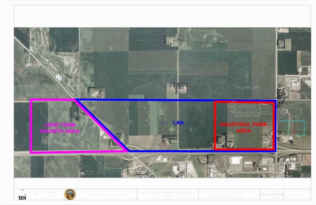
6 March 6, 2008 Master Corridor Study North Industrial/Commercial Park Prepared for the City of Worthington, Minnesota 1.0 Introduction The Worthington City Council authorized the preparation of this Corridor Study for the North Industrial/Commercial Park (NICP). The purpose of this effort is to provide the City of Worthington with a plan that examines the area outlined as future Commercial/Industrial Reserve from the Land Use Plan in the current City of Worthington Comprehensive Plan. This study will provide the City with guidance for systematically developing the area in a practical and rational method. In addition to providing an outline for the improvements, project cost estimates have been determined and provided to help the City prepare for the process. The NICP area examined in this report is generally located north of Interstate 90 and west of Trunk Highway 59. The area includes approximately 750 acres of currently undeveloped land that lies in a one-half mile strip between 27 th Street and I-90. The land in this area is mainly used for agricultural purposes and there is a small amount of elevation change over the area. The Page 1
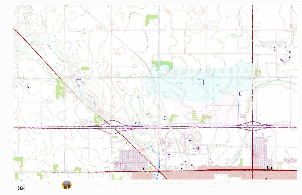
7 entire area included in the study is outlined in Figure 1 - Study Areas Corridor Study. The study area is broken into three regions based on the anticipated development timeline for the region. Sanitary service for the study area will be extended from two existing mains, located on the east end of the study area at the intersection of TH 59 and 27 th Street and the intersection of TH 59 and Bioscience Drive. The City of Worthington recently agreed to purchase approximately 115 acres of undeveloped land located on the east end of the study area. This property is generally located in the section northwest of the intersection of I-90 and TH 59 and provides the City with property adjacent to 27 th Street and TH 59. This property will be referred to as the Industrial Park area for purposes of this study. Utility services will continue to be extended from east to west within the study area so development should generally follow that pattern. The next logical region for the study includes all of the property located within the boundaries of Diagonal Road, 27 th Street, TH 59, and I-90. This area includes the three 160-acre sections of land immediately west of TH 59 and the half section created by Diagonal Road. The region is approximately 2 miles long on the north boundary, 1.5 miles south on the south boundary, and a half mile wide for a total area of approximately 560 acres. This region will be referred to as the Master Plan area for purposes of this report and includes the Industrial Park area referred to on the paragraph above. The third region of land analyzed in this study includes the remainder of the area outlined as Commercial/Industrial Reserve in the current Land Use Plan. TMaster Corridor StudyT Page 2
8 This area lies west of Diagonal Road and will be the last region of the study area to be developed, based on utility extensions. Development of this region may not occur for decades. Due to the lengthy timeline and the fact that many of the variables/conditions outlined in the design for the Industrial Park and Master Plan areas may change prior to the development of this land, much less detail is included for this region. This area will be referred to as the Long Term Growth area for purposes of this report. The City has been working with a local business to develop a site within the Industrial Park area. This business requires a twenty acre site and does not require frontage or visibility to TH 59 or I-90. Based on these considerations, and ease of extending utility services to the proposed site, a location was proposed along 27 th Street, within the property that has already been purchased by the City. The proposed site will be referred to as the 20 Acre Site for purposes of this report. This study provides recommendations on a number of design features related to developing the park including: 1. Corridor Layout and Land Use The study provides a master streets and utilities corridor plan that was developed to maximize the development potential and City s investment in the property with an additional focus on providing a degree of flexibility within the development. 2. TH 59 Intersection Layouts - During the development of the study, SEH met with City and Mn/DOT representatives to develop TMaster Corridor StudyT Page 3
9 conceptual intersection plans for TH 59 at 27 th Street and Bioscience Drive. 3. Sanitary Sewer Plan The study includes a master sanitary sewer plan to guide ultimate development of the Master Plan area in the most feasible manner. 4. Water Distribution Plan - The study includes a master water service plan that is focused on providing a level of service generally regarded as adequate for industrial/commercial service and fire suppression. 5. Storm Water Plan - A conceptual storm water master plan, including necessary detention capacity and basin locations, was developed to provide systematic regional storm water management for the study area. This plan includes a benefit analysis to determine whether a relocation of the Okabena Creek/County Ditch 12 is practical and feasible. Project cost estimates were developed from the recommended layouts and are included in this report to assist the City in planning capital improvements in the future. This plan does not take the place of detailed feasibility studies that are typically prepared prior to the design and construction of improvement projects. Due to the global nature of this study, it is general and less specific than detailed feasibility studies. Recommended improvements should be verified by a detailed feasibility study to confirm existing conditions, sizes, locations, costs, and staging for improvements. TMaster Corridor StudyT Page 4
10 2.0 Corridor Layout and Land Use The Master Plan area is surrounded by Diagonal Road on the west, 27 th Street on the north, TH 59 on the east, and I-90 on the south. There are on and off ramps for I-90 at both Diagonal Road and TH 59. Paul Street is an existing north-south gravel road that connects 27 th Street to Rowe Avenue via an I-90 underpass located between the Diagonal Road and TH 59 underpasses. Paul Street also extends to the east, immediately north of the Rowe Avenue underpass, and acts as a service road to serve a number of residential properties located between Rowe Street and TH 59. The Master Plan Area was analyzed and a number of factors were determined in developing the corridor layout for the Master Plan area, including: 1. The long, linear quality of the Master Plan site. 2. Functionality and traffic flow of proposed routes. 3. Location and mix of land uses. 4. Flexibility in final street and land use layouts. 5. Location of Okabena Creek/County Ditch 12 along the west and east ends of the park. 6. Preserving the few remaining tree windrows within the area. TMaster Corridor StudyT Page 5
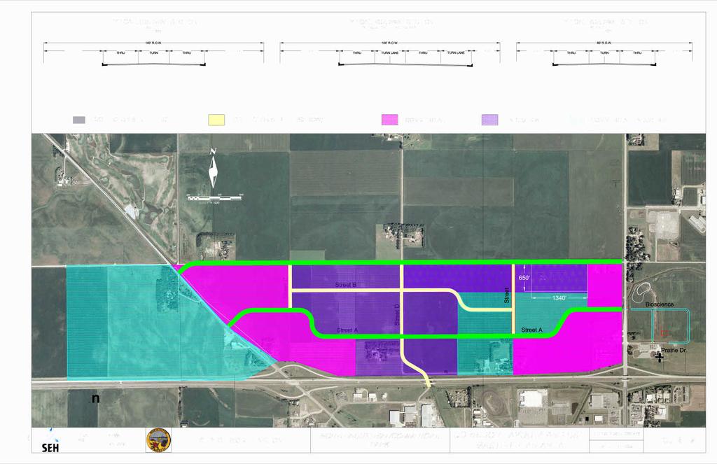
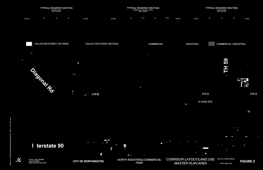
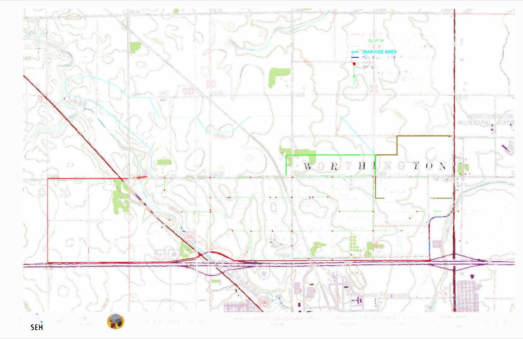
11 The proposed corridor layout and land use recommendation for the Master Plan area are shown in Figure 2 Corridor Layout/Land Use Master Plan Area. The layout recognizes the linear aspect of the site by providing two main east-west thoroughfares that provide two points of access at both Diagonal Road and TH 59. Street A will act as the main arterial for the interior park area sites and provide access to all commercial and industrial sites adjacent to I-90. A new intersection will need to be developed at both Diagonal Road and TH 59 to provide access for Street A. 27 th Street will act as the second arterial for the Master Plan site and will provide access to sites located along the north and south sides of 27 th Street. The existing intersection of 27 th Street and TH 59 will need to be improved to accommodate the increased traffic anticipated from the developed areas. The existing intersection of 27 th Street and Diagonal Road will need to be revised to provide a 90 degree intersection with Diagonal Road. A one hundred foot wide right of way corridor is recommended for both main arterial thoroughfares. This will provide enough space to develop a three lane street section with 16 wide through lanes, a 14 wide center opposing left turn lane, right turn lanes at major intersections, and sidewalk or trail separated from the street by a boulevard section. Streets B, C, D, and E will act as minor arterials for the interior of the park. Street B will serve as a secondary east-west street, providing access to sites that do not front 27 th Street or Street A and directing vehicles to either 27 th Street or Street A for access to Diagonal Road or TH 59. Streets C, D, and E provide the north-south movements necessary to intersect the east-west TMaster Corridor StudyT Page 6
12 streets. The layout proposes construction of the north-south streets at even spacing, located at the property section lines. A fifth access to the Master Plan site will be created by extending Street D south, through the existing I- 90 underpass, and connecting it to Rowe Ave. This access will provide an access point for individuals not wanting to use Diagonal Road or TH 59, as well as function as a natural connection to the businesses along Industrial Lane and Ryans Road. An eighty foot right of way is recommended for the secondary streets. This will allow for the same street section as the major arterials, minus the right turn lanes and wider boulevard sections. The street layouts were developed to provide some degree of flexibility within the Master Plan area. It is recommended that 27 th Street remain on the section line. The intersections of Street A at TH 59 and Diagonal Road are locked with respect to necessary spacing and geographical features, however once the street is constructed beyond Okabena Creek on both sides of the park, the alignment can shift slightly to accommodate specific site requirements as they may arise. Continuous alignment variations to accommodate businesses are discouraged but if the decision is made to shift Street A or Street B one hundred feet north or south of the proposed alignment, this should not greatly affect the general intent of the corridor layout. A review of the proposed utility layouts must be conducted prior to making any final decisions in regards to street alignment revisions as the utility alignments will also need to be revised accordingly. The proposed land use plan includes developing commercial businesses at the outskirts of the Master Plan area and industrial businesses within the TMaster Corridor StudyT Page 7
13 interior of the area. A third designation, Commercial/Industrial, is also included in the land use drawing to provide some degree of flexibility based on the opportunities presented to the City. This layout makes strategic sense for both the businesses and the City as it allows commercial properties frontage/visibility along TH 59, Diagonal Road, and I-90 at the exit/entrance locations while the center of the site retains the feel of an industrial campus. The commercial properties and interstate traffic will benefit from the easy access at the exit/entrance ramps, providing quick, profitable, stops from interstate travelers. The commercial businesses will also benefit from the trip generations provided by employees of the interior industrial campus going to and from work. This layout also provides the City with a good mix of land use in the Industrial Park site that the City already owns. The City can choose to attract additional job growth opportunities within the remaining Industrial and Commercial/Industrial area while generating revenue from the sale of the higher value commercial areas. The City will have to resist the urge to use designated Commercial property for Industrial uses, should the Industrial sites fill quicker than the commercial sites in the Industrial park area. This is to be expected as Commercial businesses may wait for the Industrial base to develop before moving north of the Interstate. Allowing Industrial businesses to set up shop within the designated Commercial area to simply fill the gaps may create a shortage of commercial property and/or create a number of land mix problems within the park if additional commercial property is needed in the future. TMaster Corridor StudyT Page 8
14 One final feature of the proposed corridor layout involves a guiding principle of promoting Okabena Creek and the few remaining tree windrows as amenities for the site. These will be the only remnants of the agricultural heritage and rural farmsteads that populated this area in the first place as there are few other natural features that define this site. It is recommended that the City develop these areas into planned green spaces to provide a recreational element to the Master Plan area. 3.0 TH 59 Intersection Improvements TH 59 reduces from a four-lane divided highway immediately north of I-90 to a two-lane highway as the highway continues north. Based on Mn/DOT s 2006 Traffic Volumes, TH 59 carries approximately 8200 vehicles per day. That number drops to 3800 vehicles per day north of 27 th Street and 2800 vehicles per day north of 230 th Street. Based on these volumes, the existing layout of TH 59 provides adequate capacity. The increase in traffic movements at the intersection of TH 59 and 27 th Street, along with the creation of a new intersection at TH 59 and Street A, will necessitate improvements to TH 59 in this area. A meeting with a Mn/DOT representative was conducted to determine specific requirements in regards to necessary improvements. It was determined that proposed improvements will be required at both intersections on an as needed basis. TH 59 and 27 th Street The existing intersection includes single Northbound (NB) and Southbound (SB) through lanes with a developed right-turn lane for SB traffic. Mn/DOT feels that this layout will be adequate for the increase in traffic movements initially expected by development of TMaster Corridor StudyT Page 9
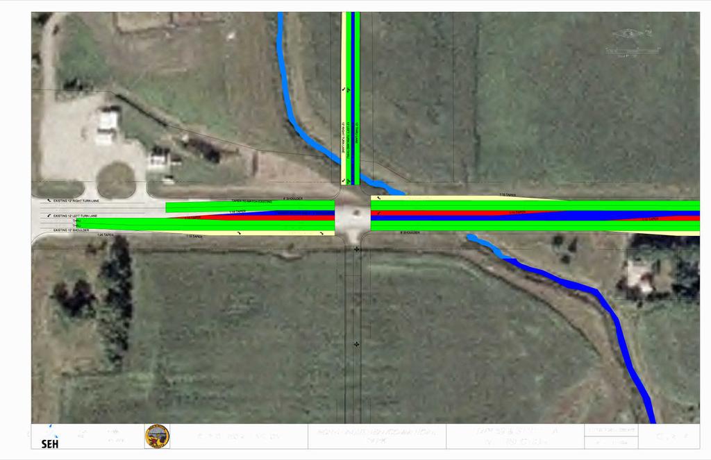
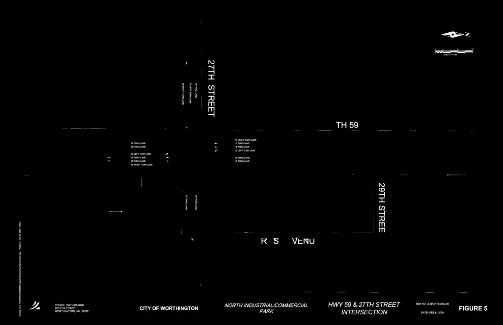
15 the proposed 20 Acre Site and Mn/DOT will not require that any immediate improvements be made at the intersection. Mn/DOT has suggested that both Mn/DOT and the City monitor the increasing traffic generation at the intersection and work together to determine when additional improvements will be needed. Mn/DOT is currently developing a number of warrants that, when triggered, would require the construction of turn lanes but the guidelines are still in draft form. Based on the draft version, some warrants that may trigger additional improvements at 27 th Street include heavyvehicles turning movements, crash history, and total vehicle volume at the intersection. Based on this information, improvements should be staged over a number of years to provide additional capacity on an as needed basis. Based on current Mn/DOT standards, Mn/DOT has to consider roundabouts for intersection control treatments. Due to the fact that improvements at TH 59 and 27 th Street will be made in the future, it is unknown whether a roundabout is the correct intersection control treatment at this time. Mn/DOT is suggesting that the City retain space in the southwest and northwest corners of the intersection to provide enough land for a potential roundabout, should that be needed. The construction of a roundabout at this location would likely require the removal of existing structures east of the intersection. The City should hold additional discussions with Mn/DOT prior to approving developments immediately west of this intersection to make a final determination on the required intersection control treatment at 27 th Street. If it is determined that a traditional intersection is adequate, staging of the improvements on TH 59 at 27 th Street should be made based on the actual traffic movements but the following order is suggested: TMaster Corridor StudyT Page 10
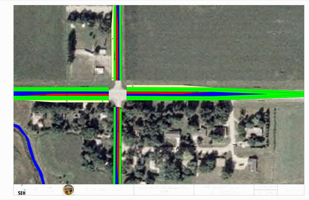
16 1. Introduction of opposing left-turn lanes for NB and SB TH Develop full right-turn lanes for NB and SB TH Develop additional through lane for both NB and SB TH 59, add center raised median in turn lane areas. 27 th Street, west of TH 59, should be improved to a minimum of 36 feet wide to provide enough room for an Eastbound (EB) through/right, EB left, and Westbound (WB) through lanes. 27 th Street, east of TH 59, should be improved on an as needed basis. The ultimate development of this intersection is shown in Figure 5 Hwy 59 and 27 th Street Intersection. TH 59 and Street A/Bioscience Drive Mn/DOT has agreed to allow one new public street intersection on TH 59 between I-90 and 27 th Street. We are proposing to create this intersection at a point that matches the existing alignment stub of Bioscience Drive in the Bioscience Industrial Park. The distance of this intersection from the westbound I-90 ramps should provide adequate spacing for vehicles to make the necessary movements on TH 59 to get into the Master Plan Area. The proposed intersection will be created by extending Street A, the main east-west thoroughfare for the NICP, to meet Bioscience Drive at this location. Street A will act as the southerly east-west thoroughfare and provide access to the properties that are adjacent the interstate. Mn/DOT has determined that expectations have been set and improvements have already been made for a traditional intersection at the proposed location TMaster Corridor StudyT Page 11
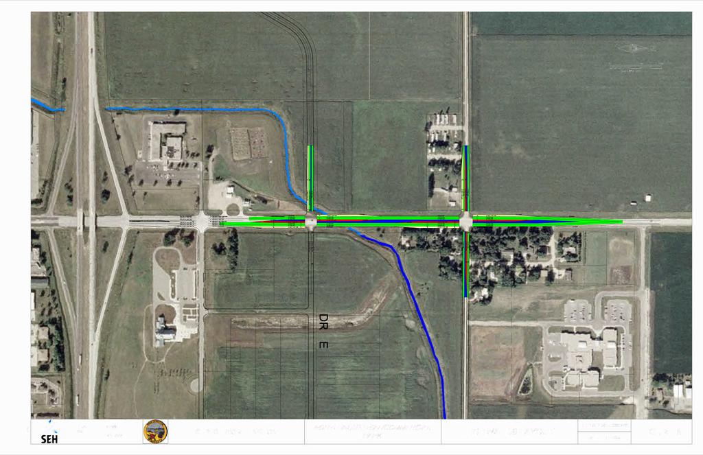
17 of TH 59 and Street A. Based on this, they will not push for consideration of a roundabout at this location. Mn/DOT is requiring that all proposed turn lanes be constructed as part of the initial intersection improvements. This will require the construction of opposing left-turn lanes and right-turn lanes for NB and SB TH 59 traffic. Bioscience Drive will need to be extended to TH 59, creating the east leg of the intersection. Street A should be constructed with a right-turn and through/left-turn lanes for the EB traffic. A raised median should be constructed to separate directional traffic and prevent left-turn access into properties immediately west of TH 59. Raised center medians and a second through-lane for NB and SB TH 59 traffic should be added as traffic counts on TH 59 warrant. The fully developed intersection plan is shown in Figure 4 - Hwy 59 and Street A Intersection. It should be noted that additional property needs to be purchased prior to the construction of this intersection as the City does not currently own the land immediately adjacent to the highway right-of-way (see Figure 15). Figure 6 Highway 59 Layout shows the lane layouts for the entire stretch of TH 59 from I-90 to where the improvements will tie back into the existing two-lane layout, north of 27 th Street. This figure represents the fully developed TH 59, with dual NB and SB through lanes and two fully developed traditional intersections. 4.0 Sanitary Sewer Plan There are currently two sanitary sewer mains located on the east end of the NICP area that are designed to provide service to the NICP area. There is a TMaster Corridor StudyT Page 12
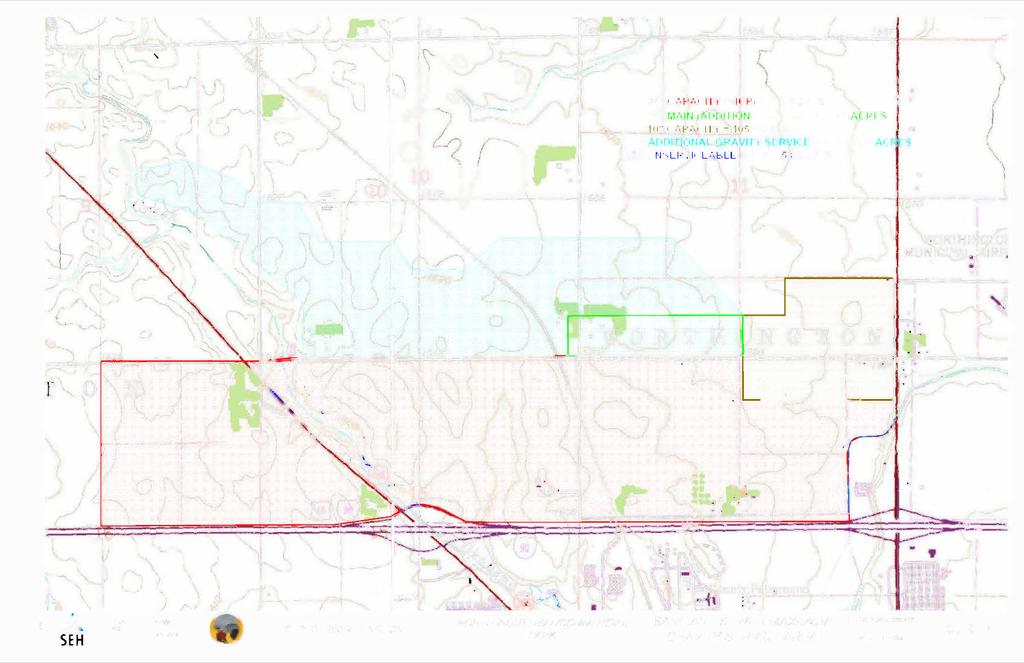
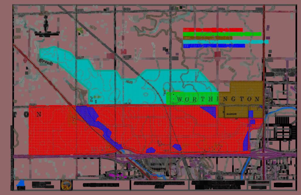
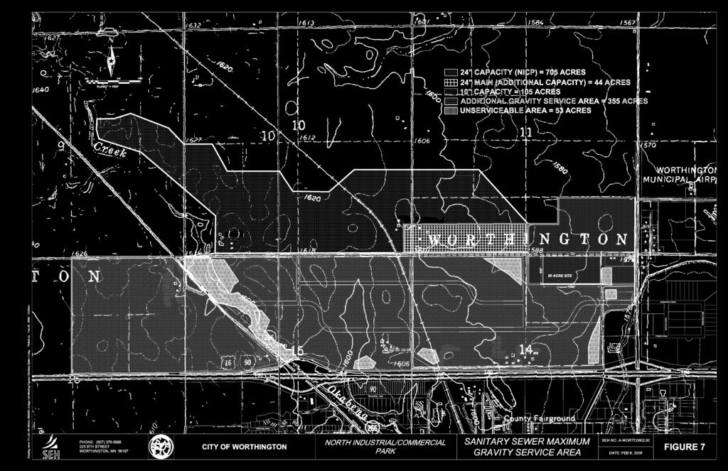
18 10 stub located at the intersection of TH 59 and 27 th Street with enough capacity to provide service for some distance west along 27 th Street. The second main is a 24 stub located at Bioscience Drive, east of TH 59. This main will provide service to the remainder of the NICP area. Anticipated wastewater flows are calculated by applying the unit flow rates for a land use type to the developable acreages associated with that land use. The flow capacities for trunk sewer main facilities are calculated using recommended guidelines based on pipe size and slope. The generally accepted design unit flow rate for Industrial/Commercial land use areas is 2,000 gallons per acre per day. Based on the proposed unit flow rate and recommended pipe guidelines, the following maximum service areas were calculated for PVC pipe installed at minimum grade: Table 1 - Maximum Service Areas Based on PVC at Minimum Grade Pipe Diameter Min Slope, S (ft/ft) 0.08% 0.10% 0.12% 0.15% 0.22% 0.28% 0.40% Flow, Q (cfs) Flow, Q (gpm) Flow, Q (gpd) Design Flow (Gal/Ac/Day) Peak Hour Factor Peak Flow (Gal/Ac/Day) Max Service Area (acres) The NICP area, including the Long Term Growth area, represents roughly 705 acres of developable land. Figure 7 Sanitary Sewer Maximum Gravity Service Area shows the proposed service areas for both existing sewer stubs, based on the service areas calculated above. TMaster Corridor StudyT Page 13
19 The table above shows that the existing 24 main has enough capacity to serve the entire NICP study area. This area is indicated on Figure 7 in red. The areas in dark blue represent unserviceable areas (detention ponds or Okabena Creek) and these areas were removed from the service area total. Based on the design criteria outlined above, the 24 has roughly 40 acres of additional capacity. This additional capacity could serve an area anywhere outside of the proposed 24 Main Capacity area (red) and is represented on Figure 7 by the area labeled 24 Main Additional Capacity (green). Table 1 indicates that a 10 main has 136 acres of Industrial/Commercial capacity. The proposed service area for the 10 main at TH 59 and 27 th Street includes property on both sides of 27 th Street for approximately one half mile and is shown in Figure 7 in brown. A second sanitary main will need to be extended north, along the west side of TH 59, to provide service to a second tier of property (shown north of the property adjacent to 27 th Street). An analysis was performed on the Industrial/Commercial users in the City s existing service area to determine the accuracy of the proposed unit flow rate. The Swift Processing Plant was removed from the analysis due to the extraordinarily large volume of wastewater produced at their facility. The analysis of all remaining Industrial/Commercial users determined that the existing unit flow rate from this land use type averages roughly 1000 gallons per acre per day, or roughly one half of the proposed design unit flow. Based on these details, a master service area was determined based on ground elevation to show the additional property that could be serviced with any excess capacity (shown in light blue). TMaster Corridor StudyT Page 14
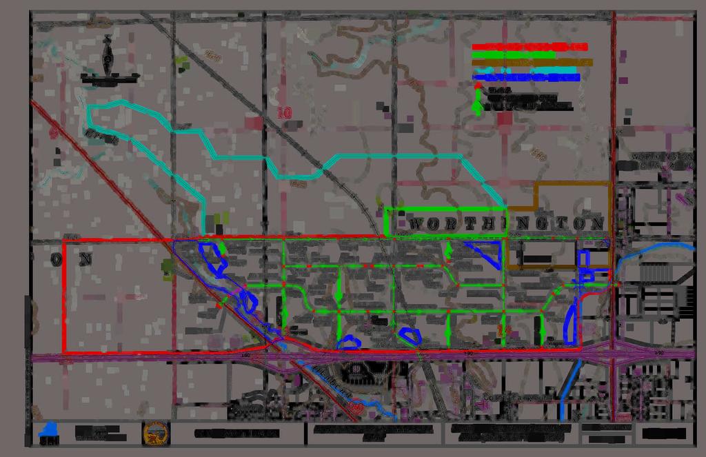
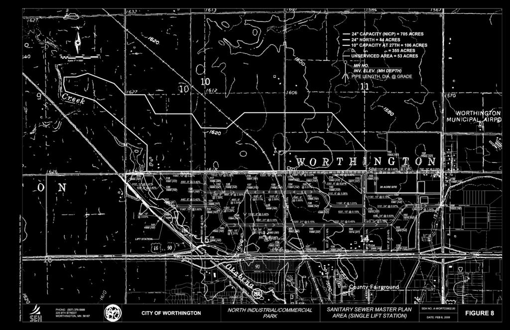
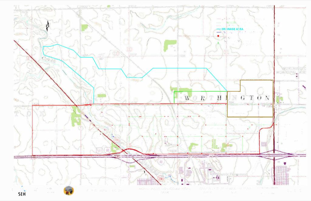
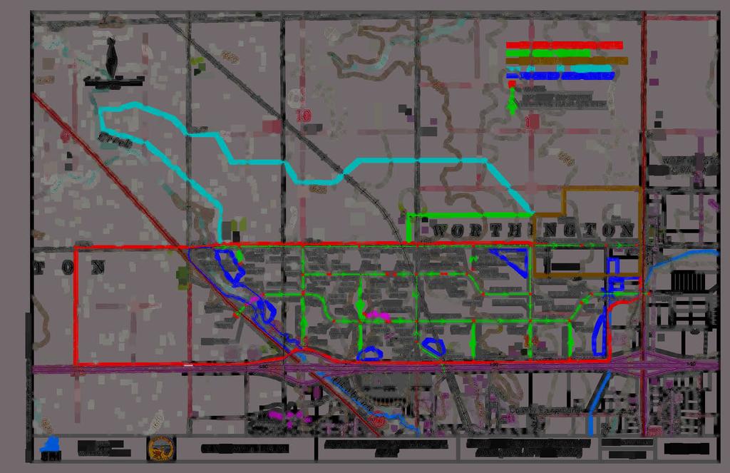
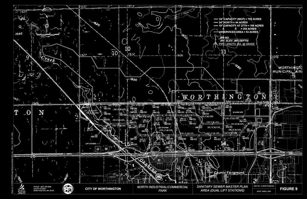
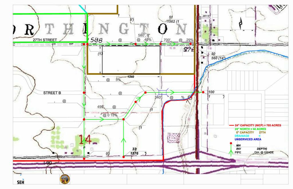
20 The existing ground generally rises in elevation across the NICP site from east to west. The two exceptions to this occurrence include the Okabena Creek area and a second low area that exists within the Master Plan site. An analysis was done to determine whether lift stations were needed at either location. Based on the existing ground elevations and the proposed sanitary sewer grades, a lift station will be required to serve the Long Term Growth area west of Diagonal Road. The analysis also determined that a second lift station within the Master Plan area was not necessary but if installed, would allow the downstream sewer mains to be constructed at shallower elevations, potentially providing a cost savings to the City. Based on this, two sanitary sewer layouts were created and studied. Figures 8, 9, and 10 show the proposed layouts for the sanitary sewer. Generally, the 10 main is shown being extended west along 27 th Street for approximately one half mile. This extension will provide service to the 20 Acre Site currently proposed along 27 th Street. The 24 sanitary main will be extended underneath TH 59 from Bioscience Drive, following Street A in a westerly direction to MH 104 (intersection of Street A and Street E). At this point, one trunk main will continue running west along Street A. This will serve all properties adjacent to and south of Street A, as well as the area west of Diagonal Road. The second trunk main will extend north of out MH 104 and continue running along Street E up to 27 th Street. This main will serve lots adjacent to Street B and 27 th Street, west of Street E. Figure 8 - Sanitary Sewer Master Plan Area (Single Lift Station) shows the sanitary sewer layout with a single lift station located adjacent to Diagonal TMaster Corridor StudyT Page 15
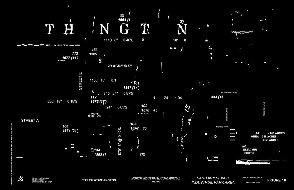
21 Road. This lift station is required to provide service to the area west of Diagonal Road and will pump into the 24 system via a forcemain under Okabena Creek. Figure 9 - Sanitary Sewer Master Plan Area (Dual Lift Stations) shows the same layout with an additional lift station added between MH 107E and MH 108. Comparing the two figures shows that construction of this lift station eliminates the need to install the gravity sewer at a depth to provide service in the low area and allows the sewer main between MH 104 and MH 107 to be constructed at a considerably shallower depth. Figure 10 - Sanitary Sewer East Industrial Park Area shows the sanitary sewer layout within the Industrial Park area. This layout is the same for both of the options outlined above as the depth of MH 104 is necessary to provide service to the west end of 27 th Street. As figure 10 shows, the extension of sanitary service from Bioscience drive must take place prior to any additional development within the Industrial Park area. 5.0 Water Distribution Plan There are a number of potential locations along the south and east sides of the park including tying into the existing water facilities including: 1. Along Diagonal Road, south of I At the intersection of Industrial Lane and Rowe Ave. 3. The existing main stubbed under I-90, west of TH 59. TMaster Corridor StudyT Page 16
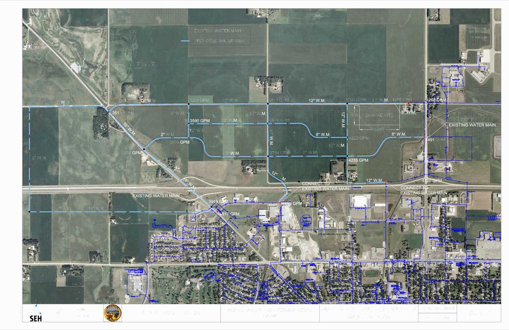
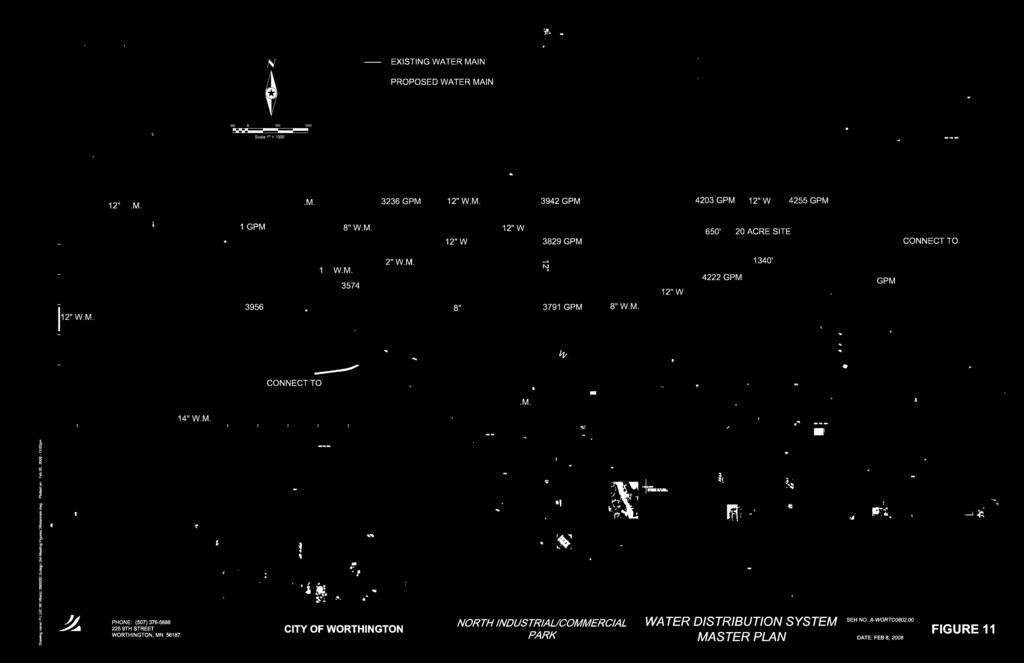
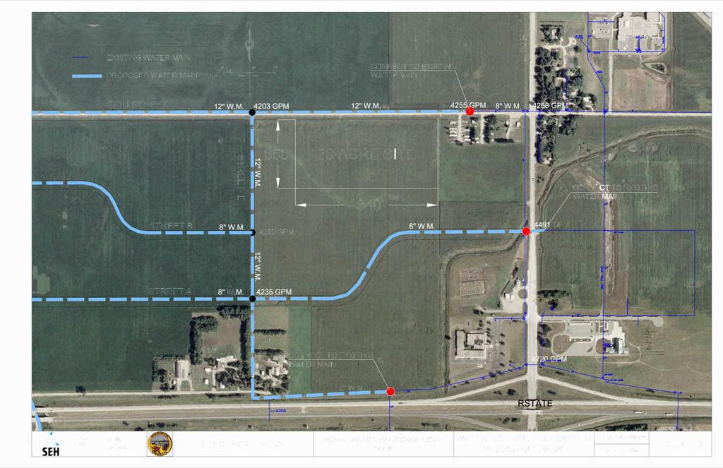
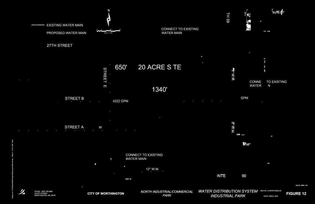
22 4. The 8 main that runs along the west side of TH 59 from I-90 to 27 th Street. The proposed water improvements in this plan have been designed to provide a minimum of 3000 gallons per minute of flow, a level of service generally considered adequate for Industrial/Commercial service and fire protection, throughout the entire NICP system. An analysis of flow data tests, taken at locations in the proximity of the NICP, was performed and a system was modeled based on the data provided. The pipes within the proposed system were sized to provide the target flow levels outlined above. Based on the system as a whole, larger diameter pipes (12 and 16 ) are needed along the outer border of the park, with smaller diameter mains (8 and 12 ) providing loops within the interior of the park. The proposed flows shown in Figure 11 Water Distribution System Master Plan and Figure 12 Water Distribution System Industrial Park are based on the construction of the entire system as a whole. A distribution system that is constructed in a loop provides much greater flows than does a single main extended. Based on this, it is recommended that the City pursue construction of water main loops (connections at both ends) when proceeding with the improvements. It is understood that this may not always be feasible and that main extensions, without secondary connections, may take place during the process. This may be the case in providing service to the 20 Acre Site as looping this main would require a large amount of additional water main construction. Due to these circumstances, it is recommended that the further analysis be conducted to determine TMaster Corridor StudyT Page 17
23 whether extending the recommended pipe size provides adequate flow. If this is not the case, a larger diameter water main may need to be extended. The results of this study were compared to the recommendations provided in the recent water study provided by Banner Engineering. Generally, the water mains recommended in this report are one size larger than the mains recommended in the Banner report. While it s difficult to determine where the difference lies, based on the limited amount of data provided for modeling in this study, a conservative approach was taken in the modeling and associated recommendations for the proposed system. Further testing should be conducted at locations immediately surrounding the park to provide a more accurate model. 6.0 Storm Water Plan All of the existing storm water from the NICP area currently runs overland into Okabena Creek/County Ditch 12, which runs along both the west and east sides of the Master Plan area. There is a small amount of existing impervious surface within the Master Plan area with a majority of the land being used for agricultural purposes. The storm water plan for the Master Plan area was developed to provide systematic regional storm water management for the entire study area. This includes design of regional detention ponds and storm water mains that may serve multiple properties. This design will prevent the need for detention facilities on each separate site. TMaster Corridor StudyT Page 18
24 The storm sewer system was designed using the rational method to calculate hydrology and Manning s equation to calculate the hydraulics based on the Master Plan area being completely developed. The storm sewer was designed for no surcharge conditions in the system during a 10-year design event. A National Pollutant Discharge Elimination System (NPDES) Storm Water Permit is required for all projects that disturb one or more acre(s), or are a part of a common plan of development disturbing more than one acre collectively. Where a project s ultimate development creates one or more acres of impervious surface, a permanent storm water treatment system is required, which is typically accomplished with a wet sedimentation pond. The design criteria for the wet sedimentation pond include a permanent pool volume of 1800 cubic feet (66.7 cubic yards) per acre of contributing watershed, a water quality volume of ½ inch of runoff from the new impervious surfaces created by the project, water quality discharge of no more than 5.66 cfs per acre of surface area of the pond, a stabilized emergency overflow to accommodate storm events in excess of the basin s hydraulic design, and energy dissipation of basin outlets. Additionally, ponds were designed to provide flow attenuation such that peak discharge rates are limited to the existing peak runoff rates of the drainage area for the 10-year (4.2 inch) and 100-year (6.0 inch), 24-hour rainfall events. In addition to the NPDES permit, a Heron Lake Watershed District (HLWD) permit is required. The HLWD has adopted the same rules as the Minnesota Pollution Control Agency s (MPCA) NPDES Construction Storm Water TMaster Corridor StudyT Page 19
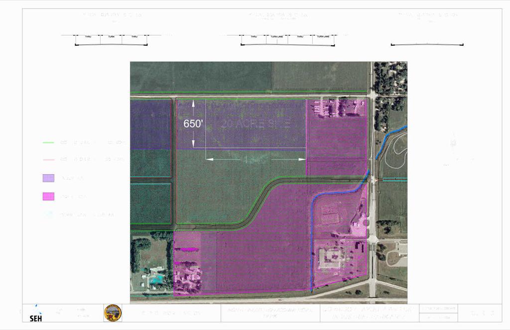
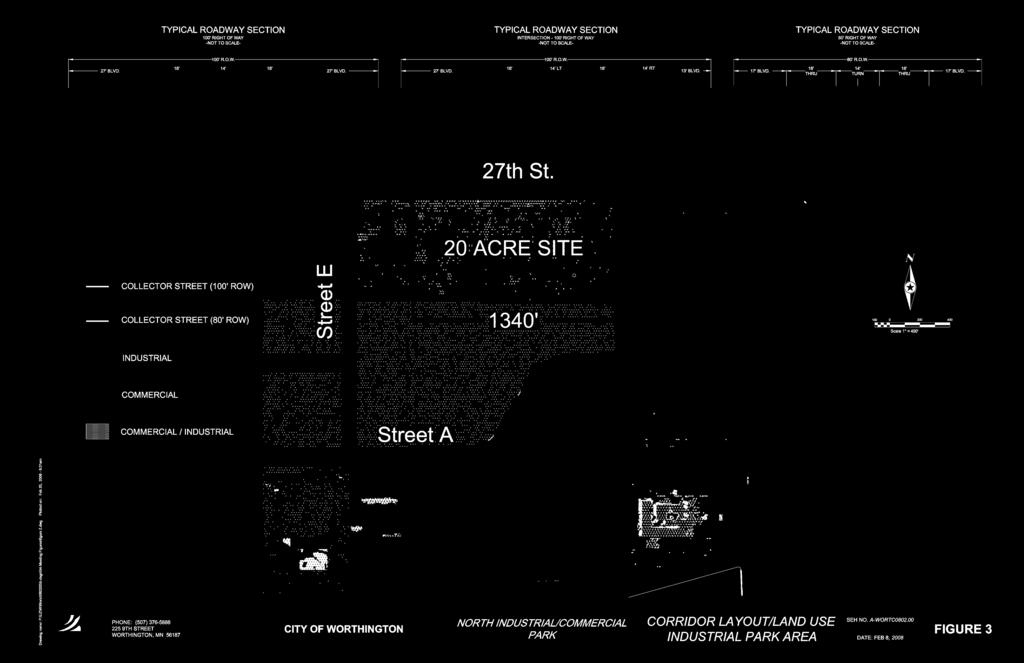
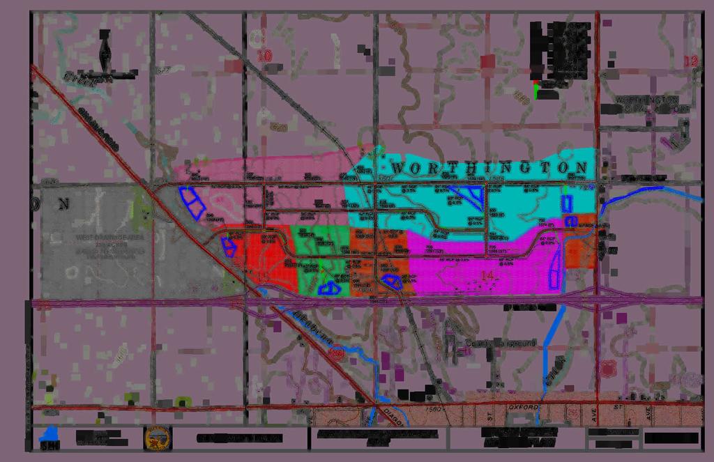
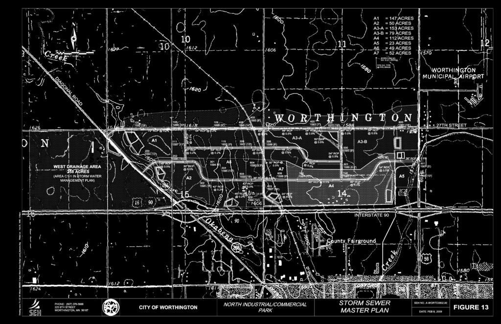
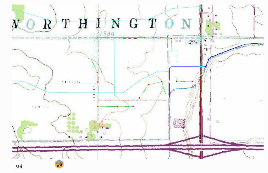
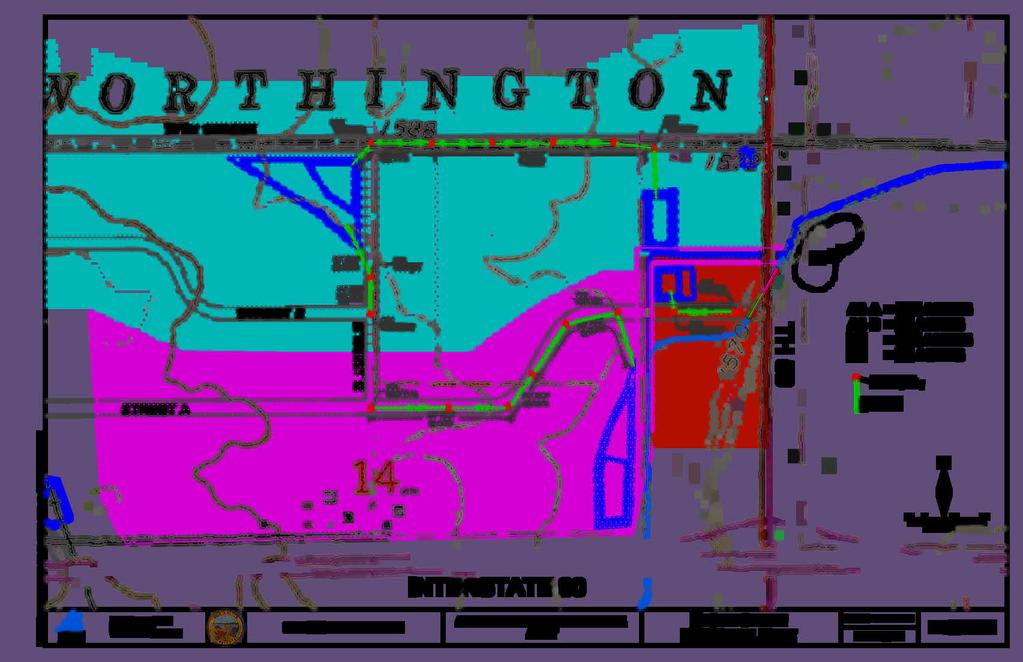
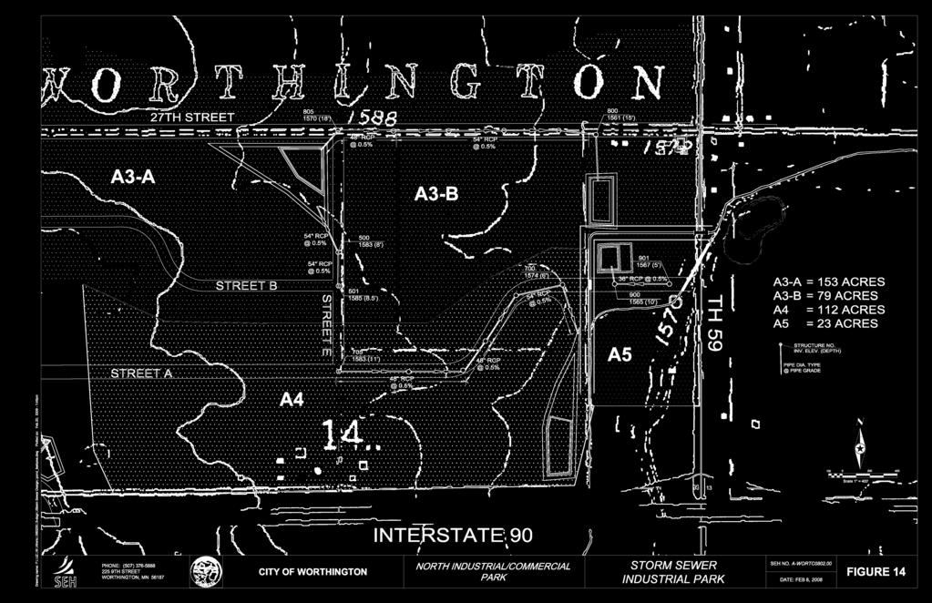
25 Permit. Both permits require temporary erosion and sediment control Best Management Practices (BMP) during construction in order to minimize sediment loss from the site and into downstream water bodies. Figure 13 Storm Sewer Master Plan shows the storm sewer design for the Master Plan area, including drainage basin areas, structure locations, invert depths, pipe sizes, and detention pond locations. The detention ponds were designed based on low points within basin areas and proximity to Okabena Creek. Ponds were also located in low lying, flood prone areas to discourage development in these locations. Figure 14 Storm Sewer Industrial Park shows the improvements that are needed for development within the Industrial Park area. Basin A3-B will transport the storm water runoff from the 27 th Street area, including the proposed 20 Acre Site. Additional property will need to be purchased to create the detention pond, as designed, for Basin A3-B. Alternatives could be pursued; however they would likely require footage along a major street that could be better served with a business. Figure 14 also shows the proposed CR 12 Ditch relocation that will be discussed in more detail in the following section. This is a planning level design based on ten foot USGS contours. Further detailed investigation will need to be conducted during final construction design to provide adequate facilities. TMaster Corridor StudyT Page 20
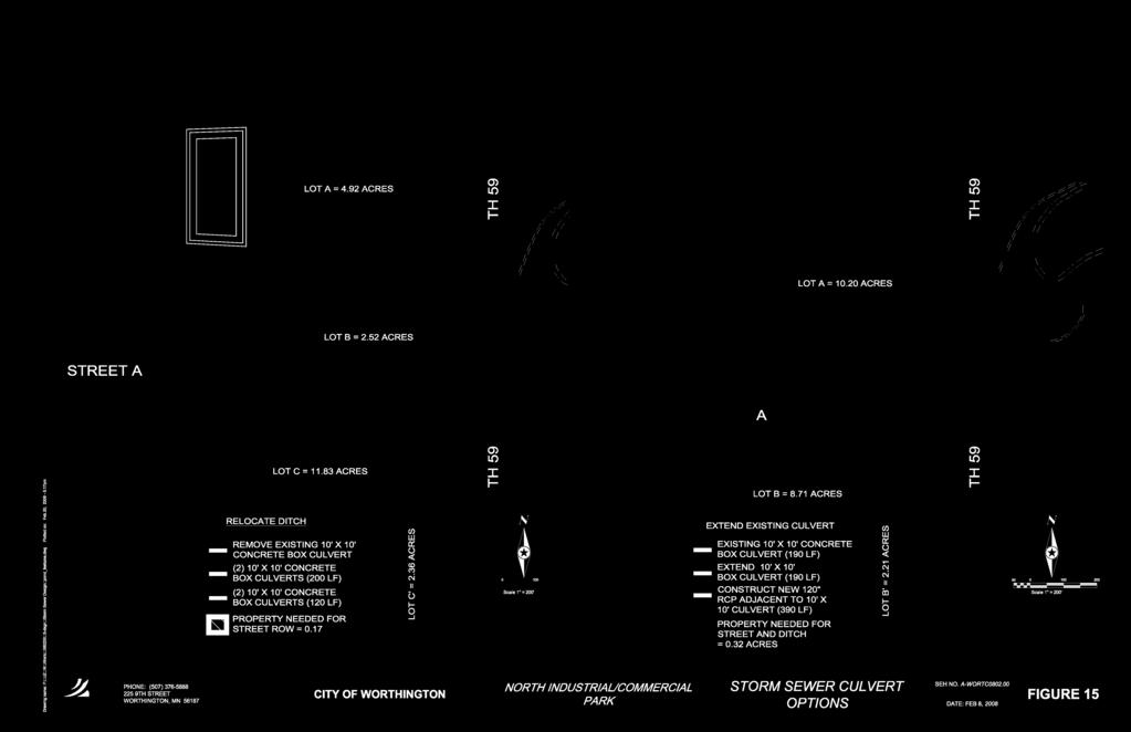
26 7.0 County Ditch 12 Relocation County Ditch (CD) 12 runs under TH 59 immediately north of the proposed intersection of TH 59 and Street A. A recent hydraulic study of the ditch has determined that the existing box culvert located under TH 59 at this location is significantly undersized to handle the flows experienced during large rain events. The study recommended the construction of a 120 concrete culvert that would run alongside the existing 10 box culvert. The existing ditch generally runs in a north-south alignment behind the businesses located west of Prairie Drive and eventually meanders to a southwest to northeast skew in the vicinity of TH 59. The existing alignment will require that the existing concrete box culvert under TH 59 be extended for the construction of Street A at the intersection. The angle of the existing ditch, relative to TH 59 and Street A, requires that additional culvert be installed to provide the necessary roadway area near the intersection. Figure 15 - Storm Sewer Culvert Options shows the proposed improvements for extending the existing culvert and installing the additional parallel culvert. Based on this option, the existing 10 box culvert under TH 59 would need to be extended an additional 190 feet for the construction of Street A. 380 feet of 120 concrete pipe culvert would also need to be installed parallel to the existing and new box culvert extension. As shown in Figure 15, the existing alignment of CD 12 does not provide adequate area to develop any commercial business south of Street A near TH 59. This area could be used as green space however this is potentially very costly real estate for the development of green space. TMaster Corridor StudyT Page 21
27 This alignment provides 10.2 acres of developable Commercial property north of Street A and west of TH 59, labeled Lot A in the Extend Existing Culvert drawing in Figure 15. It also provides 6.5 acres of Commercial property south of CD 12 and west of TH 59, labeled Lot B in Figure 15. Based on the configuration of the property east of Lot B, this lot is does not possess access to Street A or TH 59. A second crossing of CD12 would be required to provide access to Street A. This crossing would be a costly endeavor, requiring a dual set of 10 box culverts at an additional cost of approximately $150,000. A second option would be negotiating with adjacent property owners to purchase enough property to construct an access street from one of the existing TH 59 access points. Even if this street was created at an existing access, this option would not be viewed as favorable by Mn/DOT as this would create additional turning movements between the Street A intersection and the westbound I-90 ramps. The costs associated with providing access to this lot are not included in the cost estimate. A second option would be to relocate the ditch channel to create perpendicular crossings of Street A and TH 59. This would require extensive earthwork and the removal of the existing box culvert under TH 59 but would reduce the total length of new culverts constructed by 250 feet and provide access to all of the lots adjacent to TH 59. Figure 15 shows the proposed ditch relocation in the drawing on the left. The ditch relocation would create Lot A, which would require access from 27 th Street, across property that the City currently owns. Lot B and Lot C would provide nearly 12 acres of commercial property with access to either TH 59 or Street A. TMaster Corridor StudyT Page 22
28 The City has adopted the Federal Emergency Management Agency s (FEMA) National Flood Insurance Program (NFIP) and is required to adopt by ordinance and enforce the floodplain management standards which regulate development and alterations in floodplain areas. The standards set forth by FEMA are the minimum requirements and state and local requirements may be more stringent. FEMA s NFIP requires a Conditional Letter of Map Revision (CLOMR) to comment on whether proposed projects meet floodplain management standards. When any portion of a stream channel is altered or relocated, three forms are required for a CLOMR request including: 1. Overview & Concurrence Form 2. Riverine Hydrology & Hydraulics Form 3. Riverine Structures Form As part of the forms, and CLOMR requests, the following submissions are also required: 1. A project narrative 2. Hydrologic/hydraulic computations and digital model files 3. Floodplain and floodway delineations on a certified topographic map TMaster Corridor StudyT Page 23
29 4. Annotated FEMA Flood Insurance Rate Map (FIRM) to show any changes 5. Channel design criteria 6. Engineering drawings of the channelization/accessory structures 7. A sediment transport analysis Construction of the project cannot begin until the CLOMR is accepted. There are also documentation requirements during construction and once the construction is complete, an as-built survey must be completed. The as-built condition is then built into the modeling and documentation in order to determine that the conditions are consistent with the CLOMR. A LOMR request is then submitted to FEMA to reflect the new conditions. This process can be lengthy and often delays construction. The process normally takes 6 months, and in many cases even longer, as a result of the multiple reviews and processes. Some form of this process will be required to develop the property along TH 59 or relocate the creek channel.. A Minnesota Department of Natural Resources Public Waters Work Permit (PWWP) is required for any work that is done below the Ordinary High Water Level (OHWL) of a Public Water. The PWWP will be required for any relocation of the creek. TMaster Corridor StudyT Page 24
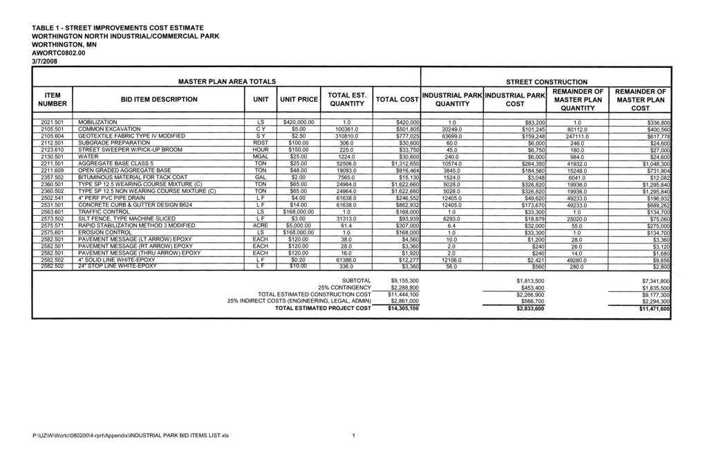
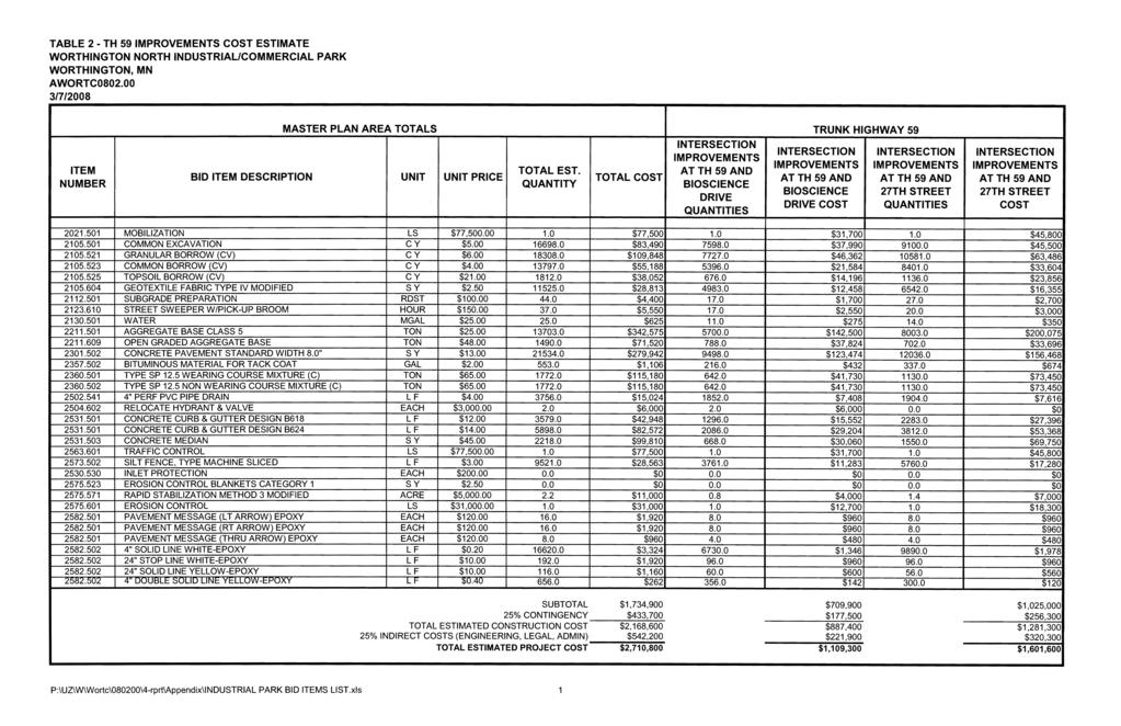
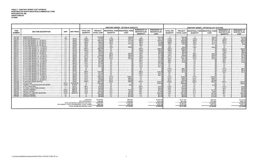
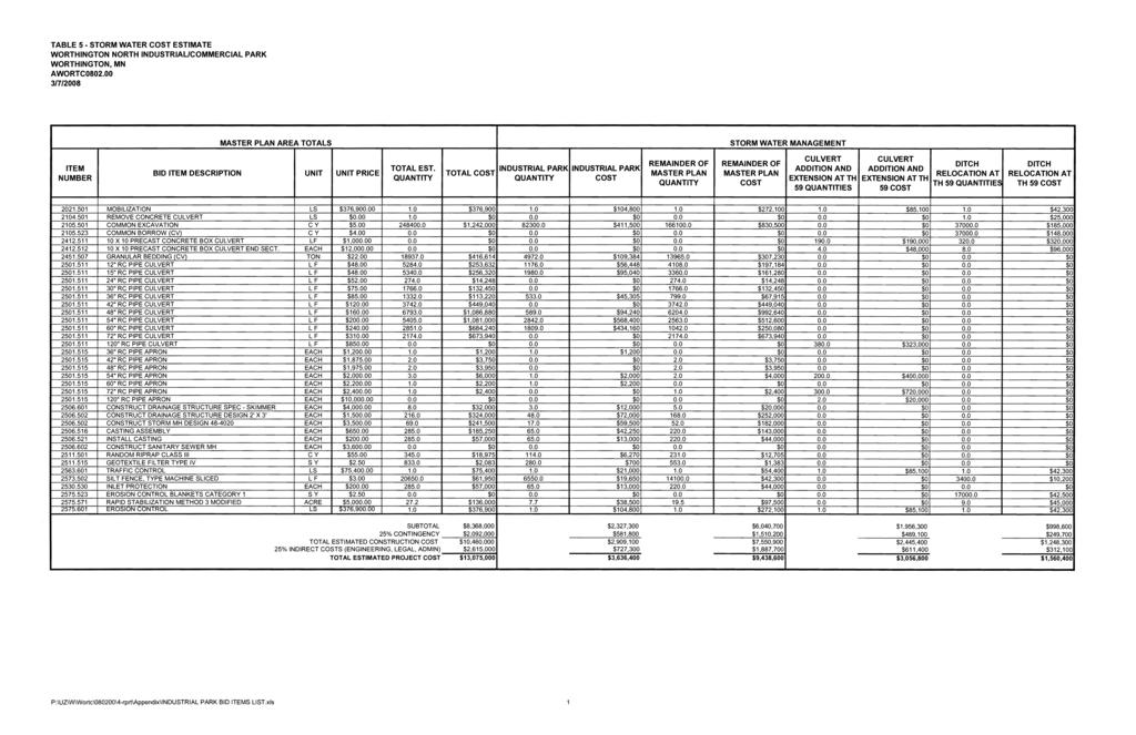
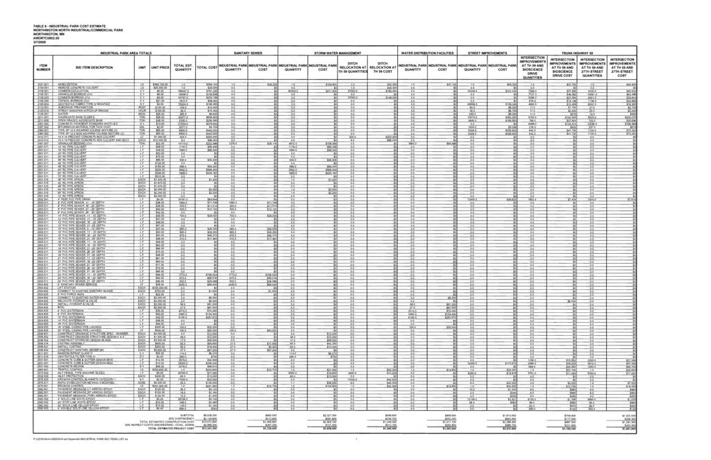
30 8.0 Estimated Project Costs Preliminary cost estimates for the proposed improvements were developed to assist the City in developing financial plans. Detailed estimates for the improvements included in Appendix A. The estimated project costs for the Industrial Park improvements include: Table 2 - Industrial Park Estimated Costs Summary Extend Existing TH 59 Culvert Relocate CD 12 Sanitary Sewer System $1,336,000 $1,336,000 Water Distribution Facilities $1,263,900 $1,263,900 Storm Sewer System $3,636,400 $3,636,400 Street Improvements $2,833,600 $2,833,600 County Ditch 12 $3,056,800 $1,560,400 TH 59 at Street A Intersection $1,109,300 $1,109,300 TH 59 at 27th Street Intersection $1,601,600 $1,601,600 Total Estimated Project Cost $14,837,600 $13,341,200 The estimated project costs for the remainder of the Master Plan Area include: Table 3 - Remainder of Master Plan Area Estimated Costs Summary Sanitary Sewer Single Lift Station Sanitary Sewer Dual Lift Stations Sanitary Sewer System $3,600,600 $3,775,600 Water Distribution Facilities $5,529,400 $5,529,400 Storm Sewer System $9,438,600 $9,438,600 Street Improvements $11,471,600 $11,471,600 Total Estimated Project Cost $30,040,200 $30,215,200 TMaster Corridor StudyT Page 25
31 The estimated project costs for the entire Master Plan Area include: Table 4 - Master Plan Area Estimated Costs Summary Extend Existing TH 59 Culvert Relocate CD 12 Sanitary Sewer System Single Lift Station $4,936,600 $4,936,600 Water Distribution Facilities $6,793,300 $6,793,300 Storm Sewer System $13,075,000 $13,075,000 Street Improvements $14,305,200 $14,305,200 County Ditch 12 $3,056,800 $1,560,400 TH 59 at Street A Intersection $1,109,300 $1,109,300 TH 59 at 27th Street Intersection $1,601,600 $1,601,600 Total Estimated Project Cost $44,877,800 $43,381,400 Based on the estimated project cost for the Master Plan area, the City would anticipate the following annual costs for developing the Master Plan area in the following time frames: Table 5 - Estimated Annual Costs to Develop Master Plan Area 2008 Estimated Project Cost Years to Develop Master Plan Area Average Annual Inflation Rate Estimated Annual Cost $43,381, % $2,354,565 $43,381, % $1,529,544 $43,381, % $1,286,414 $43,381, % $1,184,828 $43,381, % $2,632,125 $43,381, % $1,849,510 $43,381, % $1,642,819 $43,381, % $1,568,640 TMaster Corridor StudyT Page 26
32 These costs are strictly project related construction costs and do not include any considerations for land acquisition or debt interest on the financing. 9.0 Recommendations It is recommended that the Master Corridor Study for the North Industrial/Commercial Park be used as the basis for future development of the Master Plan area. This report identifies proposed improvements necessary to develop the Master Plan area. The following steps are a list of recommendations for the City to pursue to continue the development process moving forward: 1. Construct utility and street improvements along 27 th Street for the proposed 20 Acre Site. 2. Purchase land for the CD 12 Relocation and construction of detention ponds for sub-regions A3-B and A Obtain the 20 strip of land adjacent to TH 59 in the southwest corner of the intersection of TH 59 and 27 th Street. 4. Begin necessary environmental assessment work for development of Master Plan Area. 5. Begin necessary floodplain revisions for development along TH 59 and ditch relocation. 6. Purchase remaining land necessary for the construction of the intersection of TH 59 and Street A. 7. Relocate Okabena Creek/County Ditch Extend utilities from Bioscience Industrial Park. 9. Construct intersection of TH 59 and Street A. 10. Construct remaining Industrial Park area improvements. 11. Construct remaining Master Plan area improvements. TMaster Corridor StudyT Page 27
33 List of Tables Table 6 -- Sanitary Sewer Structure Schedule (Single Lift Station) Table 7 -- Sanitary Sewer Structure Schedule (Dual Lift Stations) Table 8 Storm Sewer Structure Schedule TMaster Corridor StudyT
34 TABLE 6 - SANITARY SEWER STRUCTURE SCHEDULE (SINGLE LIFT STATION) WORTHINGTON NORTH INDUSTRIAL/COMMERCIAL PARK WORTHINGTON, MN 3/6/2008 Structure No. Invert Elevation (ft) Upstream Structure No. Distance to Upstream Structure (ft) Slope (%) Elevation at Existing Grade (ft) Depth of Manhole (ft) Service Area into MH (AC) Minimum Pipe Diameter Based on Flows (in) P:\UZ\W\Wortc\080200\4-rprt\Tables\Table 6.xls
35 TABLE 7 - SANITARY SEWER STRUCTURE SCHEDULE (DUAL LIFT STATIONS) WORTHINGTON NORTH INDUSTRIAL/COMMERCIAL PARK WORTHINGTON, MN 3/6/2008 Structure No. Invert Elevation (ft) Upstream Structure No. Distance to Upstream Structure (ft) Slope (%) Elevation at Existing Grade (ft) Service Area into Depth of MH Manhole (ft) (AC) Minimum Pipe Diameter Based on Flows (in) E E W W P:\UZ\W\Wortc\080200\4-rprt\Tables\Table 7.xls
36 TABLE 8 - STORM SEWER STRUCTURE SCHEDULE WORTHINGTON NORTH INDUSTRIAL/COMMERCIAL PARK WORTHINGTON, MN 3/6/2008 Structure Number Invert Elevation Existing Grade Elevation Depth from Invert to Existing Grade (ft) Upstream Structure No. Distance to Upstream Structure (ft) Slope (%) FES FES FES FES FES FES FES FES FES FES FES P:\UZ\W\Wortc\080200\4-rprt\Tables\Table 8.xls Pipe Size (in)
37 List of Figures Figure 1 Study Areas Corridor Study Figure 2 Corridor Layout/Land Use Master Plan Area Figure 3 Corridor Layout/Land Use Industrial Park Area Figure 4 Highway 59 & Street A Intersection Figure 5 Highway 59 & 27 th Street Intersection Figure 6 Highway 59 Layout Figure 7 Sanitary Sewer Maximum Gravity Service Area Figure 8 Sanitary Sewer Master Plan Area (Single Lift Station) Figure 9 Sanitary Sewer Master Plan Area (Dual Lift Stations) Figure 10 Sanitary Sewer Industrial Park Area Figure 11 Water Distribution System Master Plan Figure 12 Water Distribution System Industrial Park Figure 13 Storm Sewer Master Plan Figure 14 Storm Sewer Industrial Park Figure 15 Storm Sewer Culvert Options
38 Appendix A Table 1 Street Improvements Cost Estimate Table 2 TH 59 Improvements Cost Estimate Table 3 Sanitary Sewer Cost Estimate Table 4 Water Distribution System Cost Estimate Table 5 Stormwater Cost Estimate Table 6 Industrial Park Cost Estimate Table 7 Project Cost Estimate
39
40
41
42
43
44
45
46
47

48

49

50

51

52

53
54
55
56

57

58

59
60
61


62
CHECKLIST FOR PHASE II DRAINAGE REPORT
 I. COVER SHEET CHECKLIST FOR PHASE II DRAINAGE REPORT A. Name of Project B. Address C. Owner D. Developer E. Engineer F. Submittal date and revision dates as applicable II. GENERAL LOCATION AND DESCRIPTION
ARGENTA TRAIL (CSAH 28/63) REALIGNMENT SOUTH PROJECT (CP 63-25)
 REALIGNMENT SOUTH PROJECT (CP 63-25)") ARGENTA TRAIL (CSAH 28/63) REALIGNMENT SOUTH PROJECT (CP 63-25) Preliminary Design Report February 2015 Prepared For: City of Inver Grove Heights Dakota County Prepared By: Kimley-Horn and Associates,
ARGENTA TRAIL (CSAH 28/63) REALIGNMENT SOUTH PROJECT (CP 63-25) Preliminary Design Report February 2015 Prepared For: City of Inver Grove Heights Dakota County Prepared By: Kimley-Horn and Associates,
13. PRELIMINARY PLAT NO MILLS FARM - Vicinity of the southeast corner of 159 th Street and Quivira Road
 13. corner of 159 th Street and Quivira Road 1. APPLICANT: HNTB Corporation is the applicant for this request. 2. REQUESTED ACTION: The applicant is requesting approval of a preliminary plat for a 383-lot
Chapter 4 - Preparation of Stormwater Site Plans
 Chapter 4 - Preparation of Stormwater Site Plans The Stormwater Site Plan is the comprehensive report containing all of the technical information and analysis necessary for the City to evaluate a proposed
MASTER DEVELOPMENT DRAINAGE PLAN FOR MONUMENT HEIGHTS
 MASTER DEVELOPMENT DRAINAGE PLAN FOR MONUMENT HEIGHTS DRAINAGE REPORT STATEMENT ENGINEER'S STATEMENT: The attached drainage plan and report were prepared under my direction and supervision and are correct
MANUAL OF DESIGN, INSTALLATION, AND MAINTENANCE REQUIREMENTS FOR STORMWATER MANAGEMENT PLANS
 MANUAL OF DESIGN, INSTALLATION, AND MAINTENANCE REQUIREMENTS FOR STORMWATER MANAGEMENT PLANS May 2007 SECTION 1 Responsibility of Applicant TABLE OF CONTENTS A. Stormwater Management Plan Required Information
Drexel, Barrell & Co.
 Drexel, Barrell & Co. June 18, 2018 Engineers/Surveyors Boulder Colorado Springs Greeley 3 South 7 th Street Colorado Springs, Colorado 80905-1501 719 260-0887 719 260-8352 Fax El Paso County Planning
When planning stormwater management facilities, the following principles shall be applied where possible.
 2.0 Principles When planning stormwater management facilities, the following principles shall be applied where possible. 2.0.1 Drainage is a regional phenomenon that does not respect the boundaries between
October 7, City of Thornton 9500 Civic Center Drive Thornton, CO (303) RE: Maverik Thornton, CO - Drainage Report
 RE: Maverik Thornton, CO - Drainage Report") October 7, 2016 City of Thornton 9500 Civic Center Drive Thornton, CO 80229 (303) 538-7295 RE: Maverik Thornton, CO - Drainage Report As per your request, we are submitting to you the drainage report and
October 7, 2016 City of Thornton 9500 Civic Center Drive Thornton, CO 80229 (303) 538-7295 RE: Maverik Thornton, CO - Drainage Report As per your request, we are submitting to you the drainage report and
Stormwater Regulations & Considerations Morse Study Area. Pam Fortun, P.E. CFM Senior Stormwater Treatment Engineer Engineering Services Division
 Stormwater Regulations & Considerations Morse Study Area Pam Fortun, P.E. CFM Senior Stormwater Treatment Engineer Engineering Services Division Stormwater Regulations Development Considerations Floodplain
Drexel, Barrell & Co.
 Drexel, Barrell & Co. December 21, 2018 Engineers/Surveyors Boulder Colorado Springs Greeley 3 South 7 th Street Colorado Springs, Colorado 80905-1501 719 260-0887 719 260-8352 Fax El Paso County Planning
PRELIMINARY ENGINEERING REPORT
 PRELIMINARY ENGINEERING REPORT GRAND AVENUE STREET & SIDEWALK EXTENSION WORTHINGTON, MINNESOTA 6-3-15 Project No. 14-16841 Table of Contents Page # Introduction... 1 Project Need... 1 Design... 1 Costs
Figure 1 Cypress Street Study Area Location Map
 July 20, 2016 TO: FROM: Jim Massarelli Director of Engineering Jeff Julkowski, PE Michael Burke, PE SUBJECT: Cypress Street Study Area Stormwater Analysis (CBBEL Project No. 16-0058) At the request of
Draft Rhode Island Stormwater Design and Installation Standards Manual
 Draft Rhode Island Stormwater Design and Installation Standards Manual Summary The May 2009 Public Review Draft version of the RI Stormwater Design and Installation Standards Manual consists of approximately
STORMWATER REPORT FOR WALMART SUPERCENTER STORE # SIOUX FALLS, LINCOLN COUNTY, SOUTH DAKOTA BFA PROJECT NO
 STORMWATER REPORT FOR WALMART SUPERCENTER STORE # 2443-00 SIOUX FALLS, LINCOLN COUNTY, SOUTH DAKOTA BFA PROJECT NO. 3286 March 1, 2012 I hereby certify that this engineering document was prepared by me
Appendix I. Checklists
 Appendix I Checklists Town of Greenwich Drainage Manual Department of Public Works - Engineering Division Town Hall - 101 Field Point Road, Greenwich, CT 06836-2540 Phone 203-622-7767 - Fax 203-622-7747
City of Waco Stormwater Management Regulations
 1.0 Applicability: City of Waco Stormwater Management Regulations These regulations apply to all development within the limits of the City of Waco as well as to any subdivisions within the extra territorial
South Bismarck Watershed Model Update and Stormwater Improvement Project
 Preliminary Engineering Report Bismarck Tribune South Bismarck Watershed Model Update and Stormwater Improvement Project City of Bismarck, ND January 2017 14.105.0046 1.0 Executive Summary The focus of
5. FINAL DEVELOPMENT PLAN APPROVAL MENORAH MEDICAL CENTER OFFICE BUILDING Vicinity of the southwest corner of 119 th Street and Nall Avenue
 5. FINAL DEVELOPMENT PLAN APPROVAL MENORAH MEDICAL CENTER Avenue 1. APPLICANT: Hoefer Wysocki Architects, L.L.C., is the applicant for this request. 2. REQUESTED ACTION: The applicant is requesting final
PRELIMINARY ENGINEERING REPORT
 PRELIMINARY ENGINEERING REPORT GRAND AVENUE STREET & SIDEWALK EXTENSION WORTHINGTON, MINNESOTA 7-25-14 Project No. 14-16841 Signature Sheet I HEREBY CERTIFY THAT THIS REPORT WAS PREPARED BY ME OR UNDER
Overall Drainage Report
 Overall Drainage Report Date: May 3, 2016 Project: Attn: Gateway at Prospect Overall Development Plan Fort Collins, Colorado Mr. Shane Boyle Fort Collins Utilities 700 Wood Street Fort Collins, Colorado
TIRZ 17/Redevelopment Authority Capital Improvements Plan Projects
 Gessner Widening: T-1701 What: Widen the road from a six-lane divided boulevard to an eight-lane divided boulevard street section, increase turn lanes, update traffic signal system, improve drainage by
STORMWATER SITE PLAN INSTRUCTIONS AND SUBMITTAL TEMPLATE Medium and Large Projects
 DEPARTMENT OF COMMUNITY DEVELOPMENT 621 Sheridan Street, Port Townsend, WA 98368 Tel: 360.379.4450 Fax: 360.379.4451 Web: www.co.jefferson.wa.us/communitydevelopment E-mail: dcd@co.jefferson.wa.us STORMWATER
Existing Conditions and Environmental Consequences Floodplains
 3.9 Environmental Consequences 3.8 3.8.1 WHAT ARE FLOODPLAINS? are low-lying areas adjacent to rivers, streams, and other waterbodies that are susceptible to inundation (flooding) during rain events. These
INDEX EXECUTIVE SUMMARY...1 BASIC INFORMATION AND PROCEDURES...3 EXISTING CONDITIONS EXISTING UTILITIES
 INDEX EXECUTIVE SUMMARY...1 INTRODUCTION...2 BASIC INFORMATION AND PROCEDURES...3 EXISTING CONDITIONS... 4-5 EXISTING UTILITIES... 6-7 MEDIAN BREAKS AND TURN LANE STORAGE REQUIREMENTS...8 PRELIMINARY DESIGN
Leduc Industrial Outline Plan SE W4
 Leduc Industrial Outline Plan SE 1-50-25-W4 Within the North Leduc Industrial ASP Prepared for: Leduc Energy Park Ltd. Prepared by: Stantec Consulting Ltd. File No. 1161 104655 V5 Table of Contents 1.0
Chapter 3 Site Planning and Low Impact Development
 CHAPTER 3 Site Planning and Low Impact Development Chapter 3 Site Planning and Low Impact Development 3.0 Introduction The City of Charleston requires that major residential, large commercial (>1 acre),
PCE PRELIMINARY DRAINAGE ANALYSIS REPORT FOR WESTWOOD MIXED USE NEIGHBORHOOD PROJECT 772 NORTH FOREST ROAD TOWN OF AMHERST, ERIE COUNTY, NEW YORK
 PCE PRELIMINARY DRAINAGE ANALYSIS REPORT FOR WESTWOOD MIXED USE NEIGHBORHOOD PROJECT 772 NORTH FOREST ROAD TOWN OF AMHERST, ERIE COUNTY, NEW YORK MAY 19, 2014 Prepared By: Timothy M. Lavocat, P.E., CFM
SITE PLAN REVIEW APPLICATION AND CHECKLIST
 SITE PLAN REVIEW APPLICATION AND CHECKLIST PROJECT SUMMARY: Project Name: City/ETA Location: City ETA (Application fee & number of copies needed are based on location) Property Location (Legal Description
Erosion & Sediment Control Plan Application Form & Checklist
 Erosion & Sediment Control Plan Application Form & Checklist GENERAL INFORMATION Application Date: Project Address: Tax Map / Parcel Number(s): PROPERTY OWNER / DEVELOPER Firm Name: Contact Person: Title:
Please highlight flow chart where applicable and return with Form 2 and Form 3 (tab 1) to the City of St. Charles Engineering Department.
 to the City of St. Charles Engineering Department.") Please highlight flow chart where applicable and return with Form 2 and Form 3 (tab 1) to the City of St. Charles Engineering Department. A $50 Permit Application fee should accompany the Permit Application.
Please highlight flow chart where applicable and return with Form 2 and Form 3 (tab 1) to the City of St. Charles Engineering Department. A $50 Permit Application fee should accompany the Permit Application.
Asbury Chapel Subdivision Sketch Plan
 Asbury Chapel Subdivision Sketch Plan PART 1: PROJECT SUMMARY Applicant: NVR Inc. Project Size: +/- 76.13 acres Parcel Numbers: 02101112,02116101,02116112, 02116113 Current Zoning: Transitional Residential
PHASE III DRAINAGE REPORT
 PHASE III DRAINAGE REPORT FOR Eastlake Assisted Living & Memory Care April 20, 2016 June 3, 2016 August 5, 2016 Prepared for: 3301 E 120 th Ave, LLC. 8200 E. Maplewood Ave., Suite 150 Greenwood Village
PRELIMINARY DRAINAGE REPORT LATHAM 200 MMSCFD GAS PROCESSING PLANT
 PRELIMINARY DRAINAGE REPORT LATHAM 200 MMSCFD GAS PROCESSING PLANT LOTS B, RECORDED EXEMPTION 1211-2-1, RECX13-0096 LOCATED IN THE NORTH 1/2 OF SECTION 2, TOWNSHIP 3 NORTH, RANGE 66 WEST, 6 TH PRINCIPAL
I-494 Rehabilitation Project SP (I-394 to Fish Lake Interchange) June 2014 Section 4(f) De Minimis Determination
 June 2014 Section 4(f) De Minimis Determination") I-494 Rehabilitation Project SP 2785-330 (I-394 to Fish Lake Interchange) June 2014 Section 4(f) De Minimis Determination State Project Number 2785-330 Federal Project No. NHPP-I494 (002) Trunk Highway:
I-494 Rehabilitation Project SP 2785-330 (I-394 to Fish Lake Interchange) June 2014 Section 4(f) De Minimis Determination State Project Number 2785-330 Federal Project No. NHPP-I494 (002) Trunk Highway:
OP Council Resolution June 16, Planning and Development Services
 OP-08-01 Council Resolution June 16, 2008 Planning and Development Services Kingsgate Landing Outline Plan Table of Contents 1.0 Introduction 1 1.1 Purpose of Plan 1 1.2 Plan Area Location 1 1.3 Ownership
New Development Stormwater Guidelines
 New Development Stormwater Guidelines CITY OF MOUNTLAKE TERRACE Table of Contents Introduction... 2 Ecology s Minimum Requirements for stormwater management... 2 Description of the 9 Minimum Requirements...
ST. MARY S SOIL CONSERVATION DISTRICT (SMSCD) AND DPW&T CONCEPT EROSION AND SEDIMENT CONTROL AND STORMWATER MANAGEMENT GUIDELINES AND CHECKLIST
 AND DPW&T CONCEPT EROSION AND SEDIMENT CONTROL AND STORMWATER MANAGEMENT GUIDELINES AND CHECKLIST") St. Mary s Soil Conservation District 26737 Radio Station Way, Suite B Leonardtown, MD 20650 Phone: 301-475-8402 ext. 3 Fax: 301-475-8391 www.stmarysscd.com St. Mary s County Government Department of Public
St. Mary s Soil Conservation District 26737 Radio Station Way, Suite B Leonardtown, MD 20650 Phone: 301-475-8402 ext. 3 Fax: 301-475-8391 www.stmarysscd.com St. Mary s County Government Department of Public
HEALTH SCIENCES BUILDING REDEVELOPMENT PROJECT
 INTRODUCTION In recent years, the University of Cincinnati (University) has demonstrated a commitment to identifying and implementing sustainable goals and objectives throughout University s Uptown Campuses.
INFRASTRUCTURE EXISTING INFRASTRUCTURE A. Circulation B. Signals C. Drainage D. Utilities
 7.01. EXISTING INFRASTRUCTURE A. Circulation B. Signals C. Drainage D. Utilities 7.02. PROPOSED INFRASTRUCTURE A. Overall Concept B. Circulation C. Signals D. Drainage 7.03. INFRASTRUCTURE MAP A. Key Infrastructure
PART 1: PROJECT SUMMARY. Proposed Land Use: 120 single-family lots. The application is Attachment A. The site plan is Attachment B.
 PART 1: PROJECT SUMMARY Applicant: JBH Development, LLC and Hopper Communities, INC Project Size: +/- 80.48 acres Parcel Number: 01513107, 01513108, 01513109, 01513113, 01513120, 01513121, 01513122, 01513124,
Appendix E Preliminary Location Hydraulic Study
 Appendix E Prepared for: State of Alaska Department of Transportation and Public Facilities Prepared by: HDR Alaska, Inc. 2525 C Street, Suite 305 Anchorage, Alaska 99503 February 2014 This page intentionally
STORMWATER MANAGEMENT CODES ANALYSIS RICHLAND COUNTY, SC SITE PLANNING ROUNDTABLE
 STORMWATER MANAGEMENT CODES ANALYSIS RICHLAND COUNTY, SC SITE PLANNING ROUNDTABLE Codes analyses for each subcommittee were completed to assist participants of the Richland County Site Planning Roundtable.
CHAPTER 9 STORM DRAINAGE. Minimum Requirements for New Development and Redevelopment
 CHAPTER 9 STORM DRAINAGE 9.01 General The standards established by this chapter are intended to represent the minimum standards for the design and construction of storm drainage facilities. 9.02 Design
Huntington Stormwater Utility
 Huntington Stormwater Utility Stormwater Management & Sediment and Erosion Control Requirements for Construction Sites Authorized by Huntington City Code Articles: 971, 970, 930, 935, 955, Revised April
Old Mill Community Association Bioretention Facility
 Project Overview This project will install a bioretention facility in a community recreation area owned by the Old Mill Community Association, Inc. Drainage from the area is currently unmanaged and has
City of Elmhurst. City of Elmhurst. Storm Sewer System Workshop November 22, 2010
 City of Elmhurst City of Elmhurst Storm Sewer System Workshop November 22, 2010 1 City of Elmhurst Watershed divide (green dashed line) through Elmhurst Area east of divide drains to Addison Creek Area
Appendix K. Stormwater Management Plan
 Regional Municipality of Halton - Steeles Avenue (Regional Road 8) Class EA - Industrial Drive to Regional Road 25/Martin Street Appendix K Stormwater Management Plan PR226401.001 Rev. 2 PR.DOT, 00/01
Major Subdivision Sketch Plan Checklist
 This checklist provides specific requirements that are apart of the Sketch process. The entire process is described by the Huntersville Subdivision Review Process which details all the submittal and resubmittal
PARISH OF ASCENSION OFFICE OF PLANNING AND DEVELOPMENT PLANNING DEPARTMENT. Joint Planning and Zoning Meeting
 1. Call To Order 2. Roll Call of Members 3. Chairman's Comments PARISH OF ASCENSION OFFICE OF PLANNING AND DEVELOPMENT PLANNING DEPARTMENT Joint Planning and Zoning Meeting January 11, 2017 6:00 PM Courthouse
PRELIMINARY PLAT DESIGN REQUIREMENTS Updated 4/8/2016
 PRELIMINARY PLAT DESIGN REQUIREMENTS Updated 4/8/2016 The following items are required for the preliminary plat. Numbers correspond with those on the example preliminary plat. RENO COUNTY SUBDIVISION REQUIREMENTS
DESIGN CRITERIA PACKAGE
 RFQ: 17-C-00003 DESIGN-BUILD SERVICES FOR THE DESIGN CRITERIA PACKAGE PREPARED BY: JAMES E. JACKSON, JR. AIA CITY ARCHITECT CONTRACT ADMINISTRATION DEPARTMENT and INTERFLOW ENGINEERING, L.L.C DESIGN CRITERIA
STORMWATER GREEN INFRASTRUCTURE AND PLANNING/ZONING BOARDS
 STORMWATER GREEN INFRASTRUCTURE AND PLANNING/ZONING BOARDS Source: Center for Watershed Protection, 2007 Southern Tier Central Regional Planning & Development Board Chemung County Stormwater Team OUTLINE
NAPA COUNTY PUBLIC WORKS Standards & Specifications
 Roadway Design & Construction Manual (Table of Contents) 1. Chapter 1: General Provisions 1.1 Short Title 1.2 Jurisdiction 1.3 Purpose and Effect 1.4 Enactment Authority 1.5 Amendment and Revisions 1.6
Village of Forest Park. July 27, Sewer Separation Evaluation
 Village of Forest Park July 27, 2015 Sewer Separation Evaluation Presentation Overview Study Background Historic Nature of Forest Park Drainage Scale of Flooding Problem Forest Park Sewer System Background
WASHINGTON COUNTY OREGON
 WASHINGTON COUNTY OREGON LONG RANGE PLANNING DIVISION North Bethany Subarea Stream Corridors: Existing Regulations In Oregon, there is a distinct difference between the land use rules that apply in rural
Coffee Creek Park Development Low Impact Development (LID)
") Coffee Creek Park Development Low Impact Development (LID) City of Duluth, St. Louis County, MN Presented By: Christopher J. Rousseau, P.E. February 27, 2008 Developer / Owner Information Trinity Development
Coffee Creek Park Development Low Impact Development (LID) City of Duluth, St. Louis County, MN Presented By: Christopher J. Rousseau, P.E. February 27, 2008 Developer / Owner Information Trinity Development
Review Zone Application for D&R Canal Commission Decision
 Review Zone Application for D&R Canal Commission Decision MEETING DATE: July 20, 2016 DRCC #: 16-4803 Latest Submission Received: June 13, 2016 Applicant: Robert McCarthy, PE PSE&G 4000 Hadley Road, 2
Mitchell Ranch South MPUD Application for Master Planned Unit Development Approval Project Narrative. Introduction
 Mitchell Ranch South MPUD Application for Master Planned Unit Development Approval Project Narrative Introduction Mitchell Ranch South is a proposed single family (detached) residential development on
Pollutant Removal Benefits
 Bioswales Bioswales Similar to biocells, but have a slight, but positive grade toward an outlet Designed to convey the WQv event at very low velocities Promote filtration through native vegetation, infiltration
SEMSWA s Role in the Land Development Process
 SEMSWA s Role in the Land Development Process One of SEMSWA s responsibilities is to ensure that any new development or redevelopment within its service area is designed and constructed in compliance with
Stormwater Retrofitting: The Art of Opportunity. Presented by the Center for Watershed Protection
 Stormwater Retrofitting: The Art of Opportunity Presented by the Center for Watershed Protection What Are Stormwater Retrofits? Retrofits are stormwater management measures inserted in an urban or ultra-urban
1. Project Description
 To: By: Checked By: Jimmy Vilce, E.I. (FOT istrict 1 Project Manager) Jennifer Nunn, P.E. (The Balmoral Group) Lori Stanfill, P.E. (The Balmoral Group) Memorandum ate: July 10, 2018 Subject: In May of
PART 1: PROJECT SUMMARY. The application is Attachment A. The site plan is Attachment B.
 Belleterre Subdivision Sketch Plan Town Board 8.7.17 Belleterre Subdivision Sketch Plan PART 1: PROJECT SUMMARY Applicant: Bowman Development Project Size: +/- 20.85 acres Parcel Number: 01115104 and 01115121
Checklists. Project Name: Location: File Number: Date of Submittal: Reviewer: Date: Applicant: Contact Name: Phone Number:
 Applicant: Contact Name: Phone Number: Email: Project Name: Location: File Number: Date of Submittal: Reviewer: Date: Concept Plan Requirements: I. General Project Information 1. Address or parcel number
S o u t h C e n t r a l O u t l i n e P l a n. Leduc Business Park. North Leduc Industrial Area Structure Plan C it y of Led u c.
 Leduc Business Park North Leduc Industrial Area Structure Plan C it y of Led u c Prepared for Farm Air Properties Inc. January, 2007 Table of Contents Page Number 1.0 Purpose of Plan and Definition of
LOUISIANA STATE UNIVERSITY COMPREHENSIVE & STRATEGIC CAMPUS MASTER PLAN. APPENDIX G - Stormwater Study Findings & Stormwater Solutions
 LOUISIANA STATE UNIVERSITY COMPREHENSIVE & STRATEGIC CAMPUS MASTER PLAN APPENDIX G - Stormwater Study Findings & Stormwater Solutions LSU: MP Narrative July 2017 3.5 Open Space Existing Conditions The
City of Dade City AMEC Project No Dade City Stormwater Master Plan September 2012 Page 32
 Page 32 3.0 MAJOR DRAINAGE SYSTEMS The 1965 Master Plan Report for Storm Drainage Facilities ( 1965 Master Plan ) identified six primary subwatersheds within the Dade City study area. Each of these areas
Storm Water Quality and Shoreline Restoration Improvements - Grant Funding Request City of Mound Carlson Park Bolton & Menk Project No.
 September 15, 2016 Brett Eidem Cost Share Grant Administrator Minnehaha Creek Watershed District 15320 Minnetonka Boulevard Minnetonka, MN 55345 RE: Storm Water Quality and Shoreline Restoration Improvements
STORM WATER UTILITY FREQUENTLY ASKED QUESTIONS
 STORM WATER UTILITY FREQUENTLY ASKED QUESTIONS In 2007, the City Council adopted Ordinance No. 1155 establishing a storm water utility in the City. No fee structure was adopted at that time. The idea of
Pond Siting Report Update
 Pond Siting Report Update Prepared for: Florida Department of Transportation District 5 CR 46A Realignment from SR 46 to North of Arundel Way Lake County, Florida FPID No. 238275-8-32-02 October 2013 (Draft
STAFFORD TRACT NORTH OF US90A 1.0 INTRODUCTION 1.1 OBJECTIVE
 1.0 INTRODUCTION 1.1 OBJECTIVE This report, prepared for submittal to TxDOT, analyzes existing and proposed detention facilities draining into the TxDOT US90A storm sewer system. The results of the detailed
Boston Water and Sewer Commission
 Boston Water and Sewer Commission 980 Harrison Avenue Boston, MA 02119-2540 617-989-7000 March 27, 2017 Michael Rooney Boston Planning & Development One City Hall Square Boston, MA 02201 Re: 159-20 1 Washington
Project: Mooney Lake Preserve Received: Location: 300 Sixth Ave. N., Orono Complete: Noticed:
 Permit Application No.: 15-445 Rules: Erosion Control, Wetland Protection, & Stormwater Management Applicant: BPS Properties, LLC Project: Mooney Lake Preserve Received: 8-24-15 Location: 300 Sixth Ave.
Application Number: SD Project Name: Walton Farms Preliminary Subdivision (acting as Master Plan)
") STAFF REPORT Town of Clayton Planning Department 111 E. Second Street, Clayton, NC 27520 P.O. Box 879, Clayton, NC 27528 Phone: 919-553-5002 Fax: 919-553-1720 Planning Board May 22, 2017 Application Number:
STAFF REPORT Town of Clayton Planning Department 111 E. Second Street, Clayton, NC 27520 P.O. Box 879, Clayton, NC 27528 Phone: 919-553-5002 Fax: 919-553-1720 Planning Board May 22, 2017 Application Number:
City of Elmhurst. Comprehensive Flood Plan. City of Elmhurst. City Council Meeting September 15, 2014
 City of Elmhurst City of Elmhurst Comprehensive Flood Plan City Council Meeting September 15, 2014 City of Elmhurst Presentation Overview Study Background Study Methodology Analysis of Three Additional
Planning Districts INTRODUCTION
 INTRODUCTION To facilitate detailed examination of development prospects for all areas of the community, Delano has been divided into 14 planning districts. The location of these planning districts is
JOB CREATION PROJECTS
 SPRINGDALE INFRASTRUCTURE DEVELOPMENT PLAN JOB CREATION PROJECTS The following pages provide a narrative description, preliminary street alignment and a preliminary construction cost estimate for each
INTRODUCTION PLANNING HISTORY
 INTRODUCTION The Upper Rock Creek Master Plan Area lies in the east central part of Montgomery County. The Master Plan Area is adjacent to the City of Rockville to the south, the Olney Planning Area to
USA Addition of South & East Side Residential Parcels. USA Deletion of a Town of Christiana Parcel. Conversion from USA to Limited Service Area
 Village of Rockdale Village of Rockdale 148 Water Street Cambridge, WI 53523 Phone 608.423.1497 Fax 608.423.9694 Urban Service Area (USA) Amendment USA Addition of South & East Side Residential Parcels
PROPOSED DRAINAGE PATTERNS
 1121 1118.50 Basin Floor 1120 1119 0 N 100 200 PROPOSED DRAINAGE PATTERNS Deroiser Drive Riverwood Drive County 260 0 100 200 Project Name: Riverwood Drive LITTLE FALLS TOWNHOMES Project Location: LITTLE
WELCOME! 8 8:30 6: TH STREET IMPROVEMENTS. Open House. Presentation & Q&A
 WELCOME! 168 TH STREET IMPROVEMENTS 6:30 Open House 7 8 Presentation & Q&A 8 8:30 Open House WELCOME Todd Pfitzer City of Omaha Engineer Bob Stubbe City of Omaha Public Works Director Jon Meyer Project
Request for Statement of Interest in Implementation of the Roosevelt Road Redevelopment Plan
 425 Hillside Avenue Request for Statement of Interest in Implementation of the Roosevelt Road Redevelopment Plan I. INTRODUCTION The is seeking the services of a qualified consulting firm to prepare plans
City of Sun Prairie Wetland Buffer Reduction Request
 City of Sun Prairie Wetland Buffer Reduction Request Westside Development Area January 9, 2017 Prepared by: City of Sun Prairie 300 E. Main Street Sun Prairie, WI 53590 BACKGROUND The City of Sun Prairie
STREAM BUFFERS
 88-415 STREAM BUFFERS 88-415-01 PURPOSE In the Kansas City region and throughout the nation, vegetated stream buffers have been clearly shown to protect stream stability and related infrastructure, improve
PepsiCo R & D Facility Expansion Town of Mount Pleasant, Westchester County, NY Draft Environmental Impact Statement Scoping Outline
 PepsiCo R & D Facility Expansion Town of Mount Pleasant, Westchester County, NY Draft Environmental Impact Statement Scoping Outline 10-17-2016 This document identifies the issues to be addressed in the
PROJECT SCOPE OF WORK CITY OF TOWN AND COUNTRY STORMWATER PROGRAM
 PROJECT SCOPE OF WORK CITY OF TOWN AND COUNTRY STORMWATER PROGRAM Project Name: 362 Featherstone Dr Project ID Number: 27-3 Problem: Anecdotal evidence suggests a natural spring exists in the backyard
REQUEST FOR COUNCIL ACTION 6A AGENDA ITEM ORIGINATING DEPT. AGENDA ITEM CITY ADMINISTRATOR APPROVAL
 DATE REQUEST FOR COUNCIL ACTION 6A AGENDA ITEM ORIGINATING DEPT. AGENDA ITEM CITY ADMINISTRATOR APPROVAL Community Development Territorial Greens PUD Concept Plan Development Stage Plan Subdivision (Preliminary
City of Petersburg, VA Stormwater Utility Frequently Asked Questions
 Q. What is stormwater runoff? A. Stormwater runoff is the water that flows off roofs, driveways, parking lots, streets and other hard surfaces during rain storms. Stormwater runoff is also the rain that
CITY OF VALPARAISO STORMWATER MASTER PLAN
 CITY OF VALPARAISO STORMWATER MASTER PLAN APPROVED BY THE VALPARAISO CITY UTILITIES BOARD OCTOBER, 2016 Prepared by the City of Valparaiso Engineering Department PLAN SUMMARY Major flash flooding in August
Advance Engineering & Surveying PLLC
 Advance Engineering & Surveying, PLLC Consulting in: Civil & Environmental Engineering Land Surveying Land Development 11 Herbert Drive Phone: (518) 698-3772 Latham, N.Y. 12110 Email:ncostape@gmail.com
7.0 SOCIAL, ECONOMIC, AND ENVIRONMENTAL ISSUES
 7.0 SOCIAL, ECONOMIC, AND ENVIRONMENTAL ISSUES The following list of social, economic, and environmental issues have been identified based on a preliminary inventory of resources in the project area, an
PROJECT BACKGROUND. Preliminary Design Scope and Tasks
 PROJECT BACKGROUND Preliminary Design Scope and Tasks The purpose of this Study is the development of preliminary designs for intersection improvements for Trunk Highway (TH) 36 at the intersections of
USF System Campus Master Plan Updates Goals, Objectives and Policies
 2015-2025 USF System Campus Master Plan Updates Goals, Objectives and Policies Tampa Goals, Objectives, and Policies Table of Contents Executive Summary 2015 2025 USF Campus Master Plan Update Introduction
FANSHAWE PARK ROAD/RICHMOND STREET INTERSECTION IMPROVEMENTS. PUBLIC INFORMATION CENTRE 2 June 16, 2016
 FANSHAWE PARK ROAD/RICHMOND STREET INTERSECTION IMPROVEMENTS Municipal Class Environmental Assessment PUBLIC INFORMATION CENTRE 2 June 16, 2016 ACCESSIBILITY Under the Accessibility Standards 2015 for
Swatara Township Stormwater Program. 1. There are no storm sewers on or near my property. Why should I pay a fee?
 1. There are no storm sewers on or near my property. Why should I pay a fee? All properties produce stormwater runoff that must be managed by the Township. Even if your property has never flooded and there
ARTICLE VI: SITE PLAN REVIEW
 Section 6.01 - Site Plan Review (All Districts) ARTICLE VI: SITE PLAN REVIEW Site plans give the Planning commission an opportunity to review development proposals in a concise and consistent manner. The
Red Fox Commercial Outline Plan
 Red Fox Commercial Outline Plan City of Cold Lake, Alberta Prepared by Durrance Projects Ltd and Ross W. Sharp & Associates Ltd October 2014 Rupert 1 Table of Contents 1. PURPOSE...3 1.1. Location...4
WEST HILL BUSINESS PARK AREA STRUCTURE PLAN
 MUNICIPAL DISTRICT OF PEACE NO. 135 WEST HILL BUSINESS PARK AREA STRUCTURE PLAN Prepared by: TABLE OF CONTENTS 1.0 Introduction... 1 1.1 Purpose of Plan........ 1 1.2 Plan Area..... 1 1.3 Existing Conditions...
BRISBANE BAYLANDS INFRASTRUCTURE PLAN FEBRUARY 2011 APPENDIX O DRAFT
 BRISBANE BAYLANDS INFRASTRUCTURE PLAN FEBRUARY 2011 APPENDIX O DRAFT PRELIMINARY STORM DRAIN CALCULATIONS ASSOCIATED WITH BRISBANE BAYLANDS REDEVELOPMENT BRISBANE, CALIFORNIA Prepared by BKF Engineers