Connecticut River Valley Project
|
|
|
- Bathsheba Wiggins
- 6 years ago
- Views:
Transcription

1 Exh. Pet. DAP-22 Connecticut River Valley Project Aesthetic Analysis Report September 4, 2015 Prepared by:
2 Aesthetic Analysis Report
3 Table of Contents Vermont Electric Power Company - Connecticut River Valley Project I. Introduction... 1 II. Project Description... 1 III. Aesthetic Analysis... 2 A. Methodology... 2 B. Description of Study Area... 6 C. Evaluation of Impacts... 6 D. Clear Written Community Standards E. Project Mitigation F. Shocking and Offensive G. Findings and Conclusion IV. References Appendices Structure Replacement Chart... Appendix A Excerpts from Town and Regional Plans... Appendix B Source Documents Evaluation of Impacts Maps and Photos... Exh. Pet. DAP-22a Landscape Mitigation Planting Plans... Exh. Pet. DAP-22b Photographic Simulations... Exh. Pet. DAP-22c Substation GIS Viewshed Maps... Exh. Pet. DAP-22d
4 Aesthetic Analysis Report
5 Connecticut River Valley Project I. Introduction T. J. Boyle Associates, LLC ( TJBA ), a landscape architecture and planning firm located in Burlington, Vermont, was retained by the Vermont Electric Power Company ( VELCO ) to conduct an aesthetic analysis to evaluate potential impacts due to the proposed Connecticut River Valley project ( CRVP or the Project ). The CRVP is a proposed electrical transmission infrastructure upgrade project in east-central Vermont. The Project will include improvements to the K31, 115 kv transmission line between Ascutney and Cavendish and to the Ascutney, Chelsea and Hartford substations. The aesthetic analysis determines whether changes to the landscape s visual character attributable to the proposed Project will be adverse, and if so, whether they will also be undue. This report presents the findings and conclusions of the aesthetic analysis. T. J. Boyle Associates has conducted field investigation, analyzed geographic information system ( GIS ) data, USGS maps, aerial photography, and detailed design plans, and used the latest computer technologies to best understand the Project and how planned improvements will alter the visual character of the landscapes for which they are proposed. II. Project Description Component 1 K31 Line Reconductor approximately 14 miles of VELCO s existing 115 kv transmission line from VELCO s Ascutney substation to VELCO s Coolidge substation, known as the K31 line. In addition, VELCO will be replacing the existing structures with new structures that in general, will have only marginal increases in height to improve the safety and reliability of the line. Purpose allows the line to be operated at a higher temperature which increases the current carrying capacity of the line with little change to the physical appearance of the existing line. Component 2 Ascutney Substation Install one, +50/ 25 MVAr Static Var Compensator (SVC) adjacent to VELCO s existing Ascutney substation. An SVC is an electrical device that uses power electronics to regulate or control system voltage. Add a new bay at VELCO s existing Ascutney substation to connect the new SVC. Purpose corrects the high/low voltage issues and provides voltage support to the system to avoid regional voltage collapse in the event of identified system outage scenarios. Component 3 Chelsea Substation Rebuild VELCO s existing Chelsea substation into a three breaker ring configuration. In a ring configuration, the breakers are looped together so that any breaker in the ring can be opened without interrupting any of the circuits. Perform condition based upgrades to some of the existing components and the protection and control equipment. Purpose allows Chelsea area load to be served from either or both of the two sources that connect to the Chelsea substation. Component 4 Hartford Substation Reconfigure the existing 25 MVAr capacitor bank at VELCO s Hartford substation into two (2) Page 1
6 Aesthetic Analysis Report 12.5 MVAr capacitor banks. Capacitors store electrical charge and are used to address low voltages issues. Perform condition based upgrades to some of the existing components and the protection and control equipment. Purpose allows more operational flexibility and allows optimal use of capacitors and the proposed Ascutney SVC. This report does not address related improvements to be undertaken by Green Mountain Power Corporation, involving reconductoring of 46 kv lines. III. Aesthetic Analysis A. Methodology Section 248(b)(5) of Title 30 of the Vermont Statutes Annotated requires that the Vermont Public Service Board find a proposed project will not have an undue adverse effect on a proposed project site s aesthetics. This requirement is outlined in the Quechee Lakes Decision (Quechee Lakes Corporation, #3EW0411-EB and #30349-EB [1986]). The Vermont Public Service Board applies the Quechee Analysis in Section 248 proceedings according to the following: In order to reach a determination as to whether the project will have undue adverse effect on the aesthetics of the area, the Board employs the two-part test first outlined by the Vermont Environmental Board in Quechee, and further defined in numerous other decisions. Pursuant to this procedure, first a determination must be made as to whether a project will have an adverse impact on aesthetics and the scenic and natural beauty. In order to find that it will have an adverse impact, a project must be out of character with its surroundings. Specific factors used in making this evaluation include the nature of the project s surroundings, the compatibility of the project s design with those surroundings, the suitability of the project s colors and materials with the immediate environment, the visibility of the project, and the impact of the project on open space. The next step in the two part test, once a conclusion as to the adverse effect of the project has been reached, is to determine whether the adverse effect of the project is undue. The adverse effect is considered undue when a positive finding is reached regarding any one of the following factors: 1. Does the project violate a clear, written community standard intended to preserve the aesthetics or scenic beauty of the area? 2. Have the applicants failed to take generally available mitigating steps which a reasonable person would take to improve the harmony of the project with its surroundings? 3. Does the project offend the sensibilities of the average person? Is it offensive or shocking because it is out of character with its surroundings or significantly diminishes the scenic qualities of the area? Our analysis, however, does not end with the results of the Quechee test. Instead, our assessment of whether a particular project will have an undue adverse effect on aesthetics and scenic or natural beauty is significantly informed by overall societal benefits of the project. Page 2
7 Vermont Electric Power Company - Connecticut River Valley Project Petitions of the Vermont Electric Power Company, Inc. (VELCO), Vermont Transco, Docket No. 6860, Vt. Pub. Serv. Bd. (Jan. 28, 2005) at 79 (footnotes omitted). In conducting the Quechee Analysis and preparing this report, the following three methods have been used: (1) background data collection, (2) GIS viewshed analysis mapping (for the converter station), and (3) field investigation. The background data and field investigation are used to characterize the study area. The GIS viewshed mapping and field investigation are used to identify areas with potential visibility of the Project. All three methods are used to evaluate whether there are in fact adverse impacts, and if so, whether those impacts could be considered undue. (1) Background Data Collection. Standard data that can help describe the landscape of the Project site, the surrounding area, and the Project are assembled. These data include available Project plans and details, aerial photography, topographical maps, Geographical Information System ( GIS ) data including digital elevation model data, water and land cover information, transportation data and primary building data (public, commercial, residential), and applicable regulations such as the town plan, zoning ordinances, sub-division regulations, and the regional plan. (2) GIS Viewshed Analysis. Following the background data collection, ESRI ArcView software is used to calculate a GIS viewshed analysis of potential visibility of the Project. Viewshed analysis mapping can identify areas that may have potential views of a project by utilizing a line of sight method from a prescribed point (such as the top of solar equipment), or points, representing the Project to all other locations within a designated study area. Figure 1 illustrates how line of sight is determined in the viewshed analysis. The analysis results (portrayed as two viewshed maps), and background data review form the basis for organizing the field investigation. a. First, a Terrain Viewshed map is created to evaluate how the land form may block views of Project upgrades. The map differentiates potential viewing areas as open areas without forest cover or areas within forest cover. However, this analysis only accounts for intervening landform and does not incorporate how vegetation, buildings, hedgerows, street trees or any other vegetation or buildings will screen visibility of the Project. This map represents the maximum potential area from which the Project could be visible. b. Next, a second map is created to represent a Vegetated Viewshed. This map shows how forest trees, in addition to landform, may block views of the Project. Two data sources where used to represent forested areas. The first data used to identify forested areas is based on the 2012 National Land Cover Database (NLCD) and is used to represent the majority of forested areas within the viewshed. Vegetation height is not provided with this data, so a conservative assumption of 40 feet has been used, even though the canopy in the study area is typically between 50 and 80 high. The screening effect of non-forest land cover (buildings, residential landscaping, hedgerows, street trees, and other roadside vegetation) cannot be incorporated with the NLCD data. The second data source is Lidar data captured specifically for the planning and design of the CRVP. Lidar is used to create a topographic survey for a particular area, but the raw data when captured, also accurately measures the height of all ground based objects, including canopy height. For the area directly around the proposed converter station, the Lidar data was incorporated into the GIS viewshed analysis. Use of the Lidar data significantly increases the accuracy of the vegetated viewshed. This map represents a more likely potential area from which the Project could be visible than the Terrain Viewshed. Page 3
8 Aesthetic Analysis Report Figure 1: Terrain Viewshed and Vegetated Viewshed Diagrams. (Please note this diagram is to illustrate the results of a GIS Viewshed analysis and is not representative of the proposed Project. When properly reviewed, these maps indicate areas most likely to have views, emphasizing areas vulnerable to the greatest impacts while also identifying areas that are unlikely to have views. The assumptions used to calculate these maps are conservative, and tend to over-estimate Project visibility. Rather than serving as a final result, these maps are primarily used in preparation of the field investigation, which more fully evaluates the landscape context, views, and potential impacts based on the visibility indicated on the maps. Therefore it is inappropriate to use these maps as the only basis to evaluate visual extent and impacts. Figure 1 illustrates the difference between the Terrain Viewshed and the Vegetated Viewshed maps. (3) Field Investigation. The viewshed maps are used to focus the field investigation on areas most likely to have views of the Project. The purpose of the field investigation is to: a. Verify potential visibility as indicated on the viewshed maps b. Photograph views toward the Project from these and any other sensitive areas (parks, public facilities, etc.) c. Photographically document the landscape s visual character within the study area d. Record notes concerning each viewpoint where photographs are taken e. Identify location of photograph viewpoints using a global positioning system ( GPS ) unit On completion of the field investigation, the GPS data is transferred to a GIS database and synchronization of the data and photograph locations are verified. Documentation of the field investigation is then prepared, which includes: (1) mapping of the routes traveled and locations of photograph viewpoints, displayed on mapping within Exh. Pet. DAP-22a (Evaluation of Impacts Maps and Photos) and Exh. Pet. DAP-22d (Substation Mapping) and a photographic inventory of existing conditions, also included in Exh. Pet. DAP-22a. Unless otherwise noted, all photos utilize a focal length approximately equivalent to 50mm on a 35mm digital single lens reflex camera, which is considered a normal lens A normal lens reproduces a field of view that generally looks natural to Page 4
9 Vermont Electric Power Company - Connecticut River Valley Project a human observer. Photo viewpoint locations and the actual photos are coordinated through indexed viewpoint numbers. (4) Project Visualization. It is normally helpful to create visualizations as an aid to evaluate visual impacts. In many situations, GIS information prepared with the viewshed analysis can also be used to create a three-dimensional (3D) model. The model can help to better understand the visual relationship of the basic landscape features to the Project elements. The advantage of this approach is the ease in representing the view from any viewpoint; the disadvantage is the relative coarseness of the data and the schematic quality of the image. Photos captured during field investigation can also be used to create realistic photographic quality simulations of a Project. The specific selection of a simulation viewpoint is based on the extent of the Project s visibility, the probable frequency and sensitivity of viewers, and the availability of a suitable photograph from the field investigation. There may be more than one viewpoint for a particular Project component. However, each simulation attempts to illustrate the most visible condition for the area it represents. The following process is used to create the simulation. a. Three-dimensional computer-aided design ( CAD ) drawings of the proposed Project elements and site plan are obtained or created. b. The CAD data is georeferenced to aerial photographs of the area, and reference markers representing fixed landscape elements visible in the photograph are added (i.e. existing buildings, utility poles, etc...) c. A viewpoint or camera view including optical characteristics of the lens used to take the photograph is created within the CAD drawing and a perspective image of the proposed Project is produced that matches the photograph. d. The perspective image is introduced as an independent layer into the digital image file of the simulation photograph. The reference markers are used to evaluate the accuracy of the perspective settings. The settings of the perspective drawing are fine-tuned to ensure the reference markers coincide with the photograph. e. Elements of the perspective drawing that will be visible are rendered into the photograph using texture and colors that occur on the site or are specified in the Project documents or from other similar projects. Photo simulations for the Project are included in Exh. Pet. DAP-22c (Photographic Simulations). TJB evaluates data from the steps above and compares existing conditions with plans for the proposed Project. The following sections of this report describe in detail the collection and evaluation of data and the resulting conclusions. Page 5

10 Aesthetic Analysis Report B. Description of the Study Area The K31 transmission line starts at the Ascutney substation in town of Weathersfield and proceeds west into the town of Cavendish. Weathersfield is located in the Vermont Piedmont physiographic region and within the Connecticut River Valley. This area consists of rolling hills and valleys at the foot of the Green Mountain. Cavendish is located in the Southern Green Mountain Region. The Green Mountains are the backbone of Vermont and in southern Vermont are characterized as a broad high plateau with a few prominent peaks. The area near the Project is predominantly forested with small villages and agricultural fields located in the valleys. Mount Ascutney is north of the eastern portion of the line, closer to the Ascutney Substation. The Project loosely follows along the Route 131 corridor, and crosses the road at three different locations. The two other substations are both located to the north of the K31 line in Hartford and Chelsea, within the Vermont Piedmont region. Figure 2: Physiographic Regions Map Detail with Proposed Project Route C. Evaluation of Adverse Impacts The following section provides an overview of changes to the visual landscape as a result of the project and whether changes will create an adverse impact to a particular area. It is first important to understand how the Project can potentially affect the visual landscape of the areas through which it is located. As previously noted, to assess adverse impacts, changes are compared to existing conditions. Since the Project consists entirely of the expansion of some infrastructure and the replacement of other infrastructure, the level of noticeable change will be limited. The assessment of impacts is based from publicly accessible locations, which primarily consist of nearby roads. A review of all locations assessed for the Project are represented in figure 3, a chart of locations with public visibility. A description of each component with the associated potential impacts is also provided. K kv Transmission Line Rebuild NOT ADVERSE The reconstruction of approximately 14 miles of VELCO s existing 115 kw transmission line from the Ascutney Substation to the Coolidge substation will consist new structures and new conductors. It should be noted that during the recent VELCO Ascutney Substation Project, the portion of the K-31 line between the Ascutney Substation and Vermont Route 131 was rebuilt to meet the standards of the CRVP and will not be changed as part of the current Project. With a few exceptions, new structures will replace existing structures near the same locations and with similar structure design, but within most instances relatively Page 6


11 Vermont Electric Power Company - Connecticut River Valley Project Figure 3: Aesthetic Impact Chart by Location Page 7

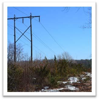
12 Aesthetic Analysis Report Figure 4: View of recent 115 kv replacement structure in foreground, with an existing structure similar to those on the K31 line in the background. Notice the extension of the poles above the cross arm. small height increases. A large portion of the height increase is to raise the shield wire, located above the phase conductors to meet current requirements for a 60 degree angle between the conductors and shield wire. This accounts for approximately 7 feet of the proposed height increase. Additional height increases were necessary to meet current clearance requirements between the phase conductors and ground at specific locations. Appendix A is a table comparing existing and proposed structure heights. This table organizes structures to the nearest road crossing and highlights the structures immediately adjacent to the specific roads. The table includes existing and proposed structure lengths (which consists of both the embedded and above ground portion of the structure). More importantly, it includes existing and proposed above ground heights, and the difference between existing and proposed heights. In general, the increase in structure heights range from less than 1 foot to 19 feet, although two structures will decrease in height and two structures will have height increases of approximately 55 feet. The large increase in height to these structure allow another two other structures located within a significant environmental resource to be eliminated. The proposed average structure height along the entire length of the K31 line is just over 55 ½ feet, which equates to an approximately 8-foot average height increase 1. The current proposal outlines 161 structure replacements plus 10 existing structures to be reused; built during the initial Ascutney Substation construction. A total of four existing structures will be eliminated as part of the reconstruction. Replacement structures will be similar in design to existing structures and will either be of wooden or steel construction. Steel construction would utilize Cor-Ten steel (weathering steel), which forms a rust-like patina and has a similar appearance as wood. The largest difference is that steel structures will retain a more consistent color, while wooden structures will weather from a dark brown to a light gray over time. A recent review of replacement structures found little to no difference in the aesthetic impact between wooden and steel structures. Steel structure would be similar in design, including X-bracing, the diameter of the poles and overall form. Figures 4 and 5 provide a comparison of recent wood and steel structure used 1 Average proposed structure heights and height increase is calculated from only the proposed 161 replacement structures. Page 8

13 Vermont Electric Power Company - Connecticut River Valley Project Figure 5: View of recent 345 kv replacement structure in foreground, with an existing wooden 345 kv structure similar in the background. on other VELCO lines within Vermont. Figure 4 shows a recent wooden structure replacement on a similar 115 kv line. Figure 5 shows a recent Cor-Ten steel replacement structure for a larger 345 kv line. Aesthetic impacts as a result of the K31 reconductoring will be very limited. The existing 115 kv line will simply be replaced with a similar sized and appearing 115 kv line. Simulation 1a and Simulation 1b, within Exh. Pet. DAP-22c, provides typical examples near road crossings to compare existing and proposed conditions. Simulated conditions have been provided for both wooden and steel structure options. Simulation 1a represents the view looking west from Vermont Route 106. The closest visible structure to the road is structure #95, which will be 9.3 feet taller than the existing structure. Structure #94, the second visible structure from the road, is proposed to be 6.3 feet taller than the existing structure. Structure #95 will also have an additional X-brace. Proposed upgrades will be very similar in appearance to the existing conditions at Vermont Route 106. The Project will not add additional transmission infrastructure, but will essentially replace what currently exists. Visual change is limited to the incremental increase in structure heights. Simulation 1b is a view looking east from Greenbush road at the intersection with Tarbell Hill Road. At this location, structure #75, the closest visible structure to the road will be relocated approximately 160 feet further east than the existing structure #75. In this case, the increase in distance from the roadway will slightly reduce the prominence of the structure. Other visible structures further east will be in similar locations as the existing. Again, the Project as viewed from Greenbush road will result in minimal visual change. Structures will be similar in design, materials and size. An average person would not perceive a material increase or substantial change in transmission infrastructure from this location. The assessment found that changes at Route 106 and Greenbush Road will not result in adverse impacts. Similarly, the aesthetic assessment found that the majority of locations along the K31 line will not be adversely impacted by proposed Project improvements. In fact, at a few locations, removal of structures, Page 9
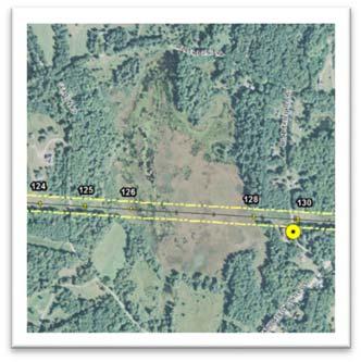
14 Aesthetic Analysis Report and slight relocations will actually decrease the prominence of transmission line infrastructure along the K31 line. Within the chart of assessed locations (Figure 3) slight structure relocations or other minor modifications are noted. At only two road crossings was the Project found to result in adverse impacts. Both of these locations have visibility of structures with large height increases. For the stretch of the K31 line between Gravelin Road and Weatherbee Hill Road, a more substantial change is proposed compared to upgrades for the rest of the line. A large wetland exists between existing structures #125 and #129, known as Beaver Pond. To avoid future impacts to this significant environmental resource, current plans propose the elimination of structures #127 and #128. To remove these structures it is necessary to relocate and substantially increase the heights of structures #126 and #129. Structures #125 and #130 will be upgraded to three-pole, guyed dead end structures. Gravelin Road is categorized as a gravel, class 3 town highway and Weatherbee Hill Road is categorized as a soil or graded and drained earth, class 3 town highway. Views of this section of the K31 line are also possible from Beaver Pond Road, which is categorized as a soil or graded and drained earth, class 3 town highway. All of these roads access rural and low density residential properties within the vicinity of the Project. Views of existing conditions along these roads are shown in Exh. Pet. DAP-22a, pages A2-14 and A3-1 through A3-7. To best understand how proposed Project upgrades will appear from these roads, Simulations 2, 3 and 4 were prepared and included in Exh. Pet. DAP-22c. Simulations 2 illustrates the view from Weatherbee Hill Road approaching the K31 corridor from the south. Views from the road are only possible within the immediate vicinity of the line crossing. An adjacent residential structure and roadside vegetation, immediately south of the corridor, significantly screen views to Structure #129 from the road as seen in simulation 2. Roadside vegetation also screen views when approaching the corridor from the north until entering the corridor crossing on Weatherbee Hill Road. Similarly, roadside vegetation screen views of structure #130 along the opposite side of the road when traveling both north and south. Structure #130 will be relocated approximately 30 feet further east from the road and structure #129 will be relocated approximately 70 feet further west from the road. However, structure #129 will have a height increase of 54.6 feet for a total height of 97 feet. Structure #130 will be converted to a three pole, guyed structure. Although views of these changes will be very brief, both of these improvement will result in an increased presence of the K31 line along Weatherbee Hill Road. Views from Gravelin Road are also very limited until within close proximity of the corridor crossing. Existing mature woods line both side of the road, north and south of the crossing (see viewpoint 40). Views to the west of the road will be very similar to the existing conditions. The closest structure west of the road, #124 will have a height increase of 7.1 feet, more or less the extension of the poles above the existing cross-arm location. However, views to the east will have visibility of structures #125, #126 and #129. Structure #124 will have a modest 7.2 height increase, but will be replaced as a 3-pole, guyed structure. Structure #125 will have a height increase of 55 feet for a total height of 97 feet, similar to structure #129. As illustrated in Simulation 3, within the limited views that are possible from Gravelin Road, upgrades to the K31 line will result in an increase presence of electrical transmission infrastructure. Views of Project upgrades at Beaver Pond can also be seen from Beaver Pond Road. At a limited number of isolated locations, views looking south are possible. Views are generally possible through clearing around a residential property (see viewpoint 37) and near the outlet of the wetland. Simulation 4 illustrates existing and proposed conditions near the outlet of the wetland. Views will be generally over 1,500 feet from Beaver Pond Road and will benefit from the removal of structures #127 and #128. Although structures #126 will be visible, it will remain back-grounded by distant vegetation and landform. The distance at which the structure is visible significantly reduces the effect of the height increase. Changes to the K31 line, as viewed from Beaver Pond Road, will not have a noticeable change to the visual landscape. Page 10
15 Vermont Electric Power Company - Connecticut River Valley Project Overall, it was determined that improvements to the K31 line will not result in adverse impacts to the aesthetics and scenic and natural beauty to the area in which the Project is located. Although it was determined that specific impacts are likely to result on Weatherbee Hill Road and Gravelin Road, these impacts are isolated and will be generally low level. Generally, the Project will replace an existing 115 kv line with a similar size and appearing 115 kv line. Visual change to the surrounding landscape will be minimal and will likely not be noticeable to the average person. Ascutney Substation Upgrade Weathersfield NOT ADVERSE The Ascutney Substation Expansion is proposed within the Town of Weathersfield located on a parcel of land adjacent to and accessed from US Route 5. US Route 5 is a paved class 40, paved US Highway and is also part of the Connecticut Scenic Byway. The site appears to be currently used for storage of construction materials and also for some minor gravel or sand excavation. There is a mix of open and forested areas within the parcel. The parcel is located within two zoning districts per the Town Zoning Bylaws, the Rural Residential district and the Industrial district. Immediately to the south is the existing VELCO Ascutney Substation and transmission line corridor, to the west is the Tenney Hill neighborhood, to the north is wooded areas, including wooded residential lots and to the east is US Route 5. Proceeding further from the substation, the Connecticut River is east of Route 5, Wilgus State Park is to the south and southwest, and Interstate 91 is to the west, beyond the Tenney Hill neighborhood. Wilgus State Park borders both sides of Route 5 south of the VELCO corridor. Proceeding north from the corridor there is a mix of uses along Route 5, including residential and wooded areas, but for approximately one-half mile, there is a predominantly industrial character. Project mapping, including viewshed analysis mapping for the Ascutney substation expansion is included in Exh. Pet. DAP-22d. Proposed upgrades at the Ascutney Substation include expanding the existing fenced yard of the substation and equipment upgrades within the existing substation yard. Expansion of the footprint will be to the north of the existing yard and will be aligned with the western fence line. The expansion will be approximately 236 feet wide by 262 feet wide. For comparison, the existing fenced portion of the substation is approximately 405 feet wide by 325 feet wide. The substation will be enclosed with an eight foot high chain link fence with one foot of barbed wire on top, similar to the fence surrounding the existing substation. There will be similar components as seen in the existing substation fence in the new yard. The project upgrades include another control building on the west side of the yard, filter capacitors east of the yard, and a series of inductors and reactors in the center of the substation yard. The Project will utilize the existing access road with Route 5, but includes a portion of new access road that will turn north of the existing road to access the new fence area to the north. Figure 6 provides an illustration of proposed upgrades for the Ascutney Substation. The existing Ascutney Substation was recently constructed as part of an earlier VELCO Project, which was completed in A portion of the K31 line was reconstructed with the existing Ascutney Substation Project and meets the requirements of the current Project. There was also a significant amount of landscape mitigation plantings installed to screen views from US Route 5 and from the Tenney Hill neighborhood. Upgrades as a result of the CVRP will result in an incremental increase of visible transmission infrastructure. The most open views of Project upgrades will be from US Route 5 near the access road as seen in Viewpoints 2 through 4. South of the Project site, US Route 5 winds through mature forest of Wilgus State Park and views are screened by a combination of landform and vegetation. North of the corridor crossing, Route 5 is characterized mostly by commercial and industrial uses including the facilities of Daniels Construction, the Hodgson Brothers Salvage Yard and the existing high voltage transmission corridor itself. A brief view north of the Project is illustrated through the salvage yard at Viewpoint 5. Page 11


16 Aesthetic Analysis Report Figure 6: Ascutney Substation Expansion Aerial Detail Map. Page 12
17 Vermont Electric Power Company - Connecticut River Valley Project Views of the substation expansion will also be possible west of the Project, from Tenney Hill Road. Tenney Hill Road is a class 3, gravel surface town roadway that provides access to the residential properties in the Tenney Hill neighborhood. Views will be through existing mature vegetation that separates the substation expansion from Tenney Hill Road and the surrounding neighborhood, as shown in photos from viewpoints 6 and 7. The Project will remove a significant portion of the existing vegetation that separates the Project site from Tenney Hill Road. The existing vegetation has a tall canopy height and sparse understory. The existing conditions, in combination with the removal of a large portion of woods is anticipated to result in views of proposed improvements and also potentially increased views of the existing substation. Views will be increased particularly during leaf-off times. Within views from US Route 5 and Tenney Hill Road that the proposed Ascutney substation expansion will be visible from, the Project will result in a noticeable increase in transmission infrastructure and will result in adverse impacts. However, the expansion will be viewed within the context of and will be similar in appearance to the existing substation. Views will also be within context of the existing transmission corridor, which contains several electrical transmission and distribution lines. Views from US Route 5 will be from a section of roadway mostly characterized by industrial and commercial uses. The extent of visibility is limited to a short stretches along both of these roadways. Otherwise, visibility of the proposed expansion will be extremely minor. To help screen and soften views that will be created, landscape mitigation is proposed. A landscape mitigation plan is include as sheet L-1 in Exh. Pet. DAP-22b. Plantings will supplement those previously installed during the construction of the existing Ascutney Substation. Overall, expansion of the Ascutney Substation as a result of the CRVP will not result in adverse impacts to the aesthetic and scenic and natural beauty of the area. Hartford Substation, Hartford NOT ADVERSE As noted in the Project description, the CRVP also includes upgrades of two VELCO substations further north from the K31 line. The Hartford Substation is located north of US Route 5 in Hartford, VT, north of the Village of White River Junction. Route 5 is a class 40, US Highway and runs north-south, generally adjacent to Interstate 91, a paved class 51 divided US interstate highway. Interstate 91 is approximately 600 feet west of the existing substation. Candlelight Terrace, the closest road to the substation, is a class 9 private road that accesses high density, multi-family townhomes. Candlelight Terrace is approximately 300 feet southwest of the substation at the closest location. Immediately surrounding the substation, the area is predominantly wooded with mature vegetation, although several electrical transmission corridors bisect the wooded areas. Further south, although US Route 5, are medium to high density residential neighborhoods in Hartford, north of White River Junction. The Connecticut River is approximately 1,400 feet east of the existing substation. A series of small trails are located in the wooded vegetation east of the substation. Project upgrades at the Hartford Substation will reconfigure the existing capacitor bank into two capacitor banks. In order to reconfigure the substation, a relatively small expansion of the existing substation yard will be necessary. Project plans show the southeastern fence line of the substation yard being relocated approximately 27 feet further to the southeast, for approximately two-thirds of the length of the southeast edge. Plans also show an approximate expansion of the yard 11 feet further to the northwest to relocate the fence off of the control building wall. The proposed expansion is represented by the yellow area in figure 7, which illustrates proposed improvements to the Hartford Substation. Although viewshed mapping, included in Exh. Pet. DAP-22d, indicates visibility of the Hartford Substation is possible from west and south of the substation, field investigation did not observe any visibility of the existing substation during leaf-on conditions. Conservative estimates of the height of surrounding Page 13


18 Aesthetic Analysis Report Figure 7: Aerial detail of the Hartford Substation Expansion. Page 14
19 Vermont Electric Power Company - Connecticut River Valley Project vegetation, as well as omissions in the GIS data, such as smaller stands of vegetation, landscape vegetation, buildings and other obstructions typically result in an over estimation of visibility in GIS viewshed mapping. This is particularly true in areas that are more developed, such as the areas west and south of the Harford substation. Viewpoints H1 through H8 represent views observed during field investigation, looking towards the existing substation. Views towards the Hartford Substation are screened by surrounding vegetation and other obstructions, and will also screen visibility of the substation expansion. Any visibility that may be possible of the expansion will view Project upgrades in the context of the existing substation infrastructure. It is unlikely that the average person would be able to decipher proposed upgrades compared to the existing conditions. Upgraded substation infrastructure will be similar in scale, color and materials as the existing substation, and the expansion of the substation yard is relatively small, compared to the overall size of the existing yard. Project improvements at the Hartford Substation will not result in adverse impacts to the aesthetics and scenic and natural beauty of the area. Chelsea Substation, Chelsea NOT ADVERSE The Chelsea Substation is the second substation to be improved, north of the K31 line. The Chelsea Substation is located off of East Randolph Road in Chelsea, VT, a paved, class 2 Town Highway. Approximately 1,300 feet east of the substation expansion is Vermont Route 110, a class 30 Vermont State Highway, oriented in a north-south direction, which accesses the village of Chelsea, approximately 2 miles to the north. Within the general vicinity of the Chelsea substation are a series of gravel and dirt surfaced, class 3 town roadways, including Brown Place and Brook Road to the north and Moxley Road, Bugbee Road and Bicknell Hill Road to the south. The Project site sits in a valley surrounded by wooded hillsides on all sides, with a mix of open agricultural fields and low density residential along the roads within the valley, as well as the First Branch of the White River and a few commercial properties. The Project is situated in an open field surrounded by dense vegetation on both the west and east side of the substation. Improvements to the Chelsea Substation will significantly expand the existing substation yard to the north and east. The northwestern fence line will be relocated approximately 34 feet to the southeast and a small expansion, approximately 5 feet is width, is proposed for approximately the western half, of the southwestern fence line. The substation will expand approximately 110 feet to the northeast and approximately 210 feet to the southeast. The proposed substation yard will be approximately three times the size of the existing yard. To accommodate the revised location of equipment within the yard, transmission lines immediately outside of the substation will be slightly reconfigured, with replacement structures for one span to the northwest of the substation and two spans to the southeast of the substation. The proposed expansion of the substation yard will occupy what appears to currently be open agricultural fields. Some limited clearing will be necessary, both to the northwest and southeast of the substation, to accommodate the reconfiguration of the transmission lines. The substation yard will be enclosed with an eight foot high chain link fence with one foot of barbed wire on top, similar to the fence surrounding the existing substation. Project upgrades include a new control building on the west side of the yard, filter capacitors east of the yard, and a series of inductors and reactors in the center of the substation yard. The existing control building footprint is 20 by 20 feet and will increase to 32 by 70 feet. The overall mass of equipment in the substation yard will increase, although the materials, colors and general appearance of equipment will be similar to existing equipment. The Project will utilize the existing access road, which will be improved from 11 foot wide to 24 feet wide and will be regraded. The improved access road will split into a horse shoe shape as it approaches the northwestern fence line, to allow separated access points into the revised substation yard. Proposed grading will also be necessary for the southeast expansion of the substation yard. Page 15


20 Aesthetic Analysis Report Figure 8: Aerial detail map of the Chelsea Substation expansion changes. The existing substation yard is shown in the red highlighted area. Page 16
21 Vermont Electric Power Company - Connecticut River Valley Project At its closest point, East Randolph Road is over 550 feet from the Chelsea Substation, which offers the closest potential public views towards the Project site. Although GIS viewshed mapping indicates possible visibility for over a 1,500 foot stretch along East Randolph Road, field investigation found very minimal visibility of the existing substation during leaf-on conditions. The topography and wooded vegetation to the west, east and south of the substation restrict most views, except at the cleared curb cut of the access road, which is over 1,000 feet from the existing substation. Visibility is most pronounced when traveling east near the curb cut, where the traveler s line of sight is directed down the cleared right-of-way and access road at the substation as seen Viewpoint C2. The taller substation components are visible, but are back-grounded by the wooded hillside beyond. This view is very brief for less than 200 feet along East Randolph Road. Traveling west visibility is limited due to the roadside and middle ground vegetation predominantly screening the substation (see Viewpoints C3, C5, and C9) and traveler s lines of sight are oriented away from the substation near the access road curb cut. It is likely that some intermittent views are possible during leaf-off times of year, but any visibility would be highly filtered by the surrounding vegetation and substation components are back-grounded by the wooded hillside. Similarly, field investigation found little to no visibility of the existing substation from Route 110, Brook Road, Moxley Road, Bugbee Road, and Bicknell Hill Road. At most, only a brief glimpses of the tallest existing substation components poke above the vegetation immediately surrounding the substation as illustrated in photos from Bugbee Road and Moxley Road, viewpoints C10, C11 and C12. Views from the south also include visibility of what appears to be an existing quarry, which has a much larger visual magnitude within views than visible electrical transmission infrastructure. From the more traveled Route 110 no visibility of the existing substation was observed. Topography and vegetation along the west side of the road screen potential views as seen in Viewpoint C7 and C8. While proposed upgrades to the Chelsea substation will significantly increase the size of the substation, it is not anticipated that upgrades will significantly increase visibility. Only minimal clearing of the surrounding vegetation will be required. Vegetation and topography will continue to mostly screen views of the substation. Views that will be most impacted include isolated locations that already have views of the substation and will likely see the tops of new infrastructure, including steel support structures and lightening masts. Most of these views already include visibility of the surrounding transmission lines. Substation upgrades will be similar in material, color and form as the existing substation equipment. The Project will not substantially increase visibility of transmission infrastructure within the area. Within views that will exist, the Chelsea Substation and transmission lines are an existing component of the visual landscape. The Project will not significantly increase the visual appearance of transmission infrastructure compared to current conditions. Upgrades to the Chelsea Substation will not result in adverse impacts to the aesthetics or scenic or natural beauty of the area. Summary In conclusion all improvements assessed as part of the CRVP are within areas of the existing transmission infrastructure. Project upgrades will only replace or expand existing facilities. In general, Project changes will result in a minor incremental addition to the size and appearance of transmission infrastructure within the Project area. Potential adverse impacts have been identified at only 4 locations, all of which are consider minor, and these specific locations combined represent an extremely small percentage of the entire Project. Since these impacts are dispersed over a relatively large geographic area, the overall impact caused by the Project are minor. Overall it was determined that the CRVP will not result in adverse impacts to the aesthetics and scenic and natural beauty of the area. Although it is concluded that the Project will not have an adverse impacts, the second prong of the Quechee test in analyzed below in the event in ti concluded that any portion of the Project will have an adverse impact. Page 17
22 Aesthetic Analysis Report D. Clear Written Community Standards Although Section 248 does not require local permitting of projects seeking a Certificate of Public Good, local plans and regulations are reviewed under the second prong of the Quechee analysis (described in Section III of this Report) where it has been determined that a Project may have an adverse visual impact. Under Quechee, this involves an assessment as to whether or not a project violates a clear, written community standard intended to preserve the aesthetics or scenic beauty of the area. The Public Service Board has noted that [i]n order for a provision to be considered a clear, written community standard, it must be "intended to preserve the aesthetics or scenic beauty of the area" where the proposed project is located and must apply to specific resources in the proposed project area. Petition of Georgia Mountain Community Wind, LLC, Docket No. 7508, Order of Vt. Pub. Serv. Bd. (Jun ) at 52. There, the Board clarified that generalized statements and general scenic resource policies that are not focused on a particular scenic resource or that fail to offer specific guidance or measures to protect the resource cannot be considered clear written community standards. Id. at 53. To determine if the CRVP will violate a clear written community standard, available local and regional planning documents were reviewed, including the Cavendish Town Plan, adopted August 28, 2013 (Cavendish Town Plan), the Town of Weathersfield Town Plan, readopted September 17, 2009 (Weathersfield Town Plan), the Chelsea Town Plan, adopted September 26, 2014 (Chelsea Town Plan), the Town of Hartford Master Plan, adopted May 27, 2014 (Hartford Town Plan), the Two Rivers-Ottauquechee Regional Plan, adopted June 27, 2012 (Two Rivers Regional Plan), and the Southern Windsor County Regional Planning Commission 2014 Regional Plan, adopted November 18, 2014 (Southern Windsor Regional Plan). A selection of excerpts from the town and regional plans relating to clear written community standards are provided in Appendix B. Summary When evaluating the CRVP against language and standards in the town and regional plans, the Project will not violate a clear written community standard. As determined by the evaluations of adverse impacts, the Project will result in minimal change to the visual landscape and therefore has little potential to result in adverse impacts to the aesthetics or scenic quality of the areas in which it is located. As is typical with Town Plans within the state of Vermont, Cavendish, Weathersfield, Hartford and Chelsea all acknowledge the importance of scenic quality within their respective town plans. Generalized statements within all the town plans can be found which call for the preservation of the scenic, rural or agricultural character of the area. Much of the language regarding aesthetics and scenic quality could not be considered clear written community standards. These generalized statements do not provide specific view locations or guidance on how to protect scenic quality. However, Cavendish, Weathersfield and Harford do provide specific scenic views within each of their plans. A review of these specific views found that proposed Project upgrades will not be visible or will not result in impacts within any of these views. Overall, the Project is consistent with all of the provisions of the town plans for the communities in which the Project will be located. Even if the Project were within scenic views, the limited visual change that will result from Project upgrades will not create a material change to the existing quality of views. The regional plans cover a wide range of topics for the regions, including land use, housing, economics, cultural resource and other community issues. At the regional level, policies and goals are somewhat broader regarding scenery and aesthetic protections. Although scenic quality is clearly identified and an important resource in both of these plans, as is often true of Regional Plans, encouragement is offered for the constituent towns to review their own needs and desires. There are rarely any specific guidelines for Page 18
23 Vermont Electric Power Company - Connecticut River Valley Project scenic quality control. Even when more specific language is provided, such as within the Southern Windsor Regional Plan, which highlights a limited number of important scenic features, the regional plans fail to provide guidance on how to appropriately protect these resources. In conclusion, the review of community standards found that the Project largely complies with the intent to protect the scenic quality within the communities that the Project is located. The CVRP will not violate any clear written community standard intended to preserve the aesthetic and scenic beauty of the area that the Project is located within. E. Project Mitigation The CRVP employs several forms of mitigation to significantly reduce the aesthetic impacts of the Project including: First and foremost, VELCO evaluated several options to address local and regional system reliability issues. Many of the alternatives included much more visible options, such as additional or much larger transmission lines. The selected alternative will by far have the least aesthetic impact. The entire 15 mile length of upgrades to the K31 transmission line will be located within an existing transmission line corridor. Essentially, proposed upgrades will replace an existing 115 kv transmission line with a new 115 kv transmission line. The K31 Line is an existing high-voltage transmission line and is an established part of the existing landscape. Proposed upgrades consist of in-kind replacement of existing structures and transmission infrastructure. Overall, replacement structures will be of similar design and appearance with minimal height increases. Upgrades to the K31 line will not create additional visibility of transmission infrastructure in the area. Upgrades proposed for three substations as part of the Project, will result in minimal increases to visibility of electrical transmission infrastructure within the areas they are located. Expansions to each of the three substations are located in areas that will result in the least amount of potential visibility. Substation improvements have been designed to minimize required removal of vegetation. Additional landscape mitigation plantings are proposed to screen and soften views that may be created of the Ascutney Substation expansion. Between the design of proposed infrastructure and the careful siting of proposed improvements, the CVRP will result in minimal impacts. Considering all improvements were able to be located within or immediately adjacent to existing infrastructure will significantly diminish potential noticeable changes to the landscape in which the Project is located. The CRVP successfully incorporates reasonable mitigation as part of the Project. Page 19
24 Aesthetic Analysis Report F. Shocking and Offensive When evaluating whether a Project would offend the sensibilities of the average person, the criteria to make this assessment is related back to the first part of the Quechee Test; how the Project fits within its surroundings. An average person is considered a disinterested party, not an affected neighbor. The threshold for a Project to be shocking or offensive is high and a project would need to be entirely inconsistent with the surrounding land uses or exceptionally out of scale with the surroundings. The Project effect on aesthetics as a whole was found not to result in adverse aesthetic impact, even though adverse impacts were identified at four specific locations as described in the Evaluation of Adverse Impacts. The level of these impacts would be very low and represent an extremely small percentage of the entire Project. However, even if it were determined that the Project as a whole resulted in an adverse impact, it would not offend the sensibility of the average person. The CVRP will not be offensive or shocking. This determination is based on a number of factors that were assessed during the aesthetic analysis. The Project will either replace or expand existing electrical transmission infrastructure, which is an established part of the existing visual landscape. As illustrated in Simulations 1a and 1b, upgrades to the K31 line will have a very similar appearance for most of the line as compared to the existing conditions. Proposed substation upgrades will simply expand and reconfigure existing substations. Proposed upgrades in general will utilize similar color, material and form to existing infrastructure within the same location. The Project design will not require any significant removal of vegetation, which will retain the existing screening effect provided by surrounding vegetation. The Project is proposed at a location that does not include unique or protected scenic qualities. Electrical transmission lines and substations are a common element throughout Vermont landscape. Proposed changes as part of the CRVP will have a minimal effect of the aesthetics for the area in which the Project is located. The Project could not be considered offensive or shocking when compared to the existing conditions of these areas. Page 20
25 Vermont Electric Power Company - Connecticut River Valley Project G. Findings and Conclusion Although the Project will result in adverse impacts at 4 specific locations, overall it was determined that the Project will not result in adverse impacts to the aesthetics and scenic and natural beauty of the area that it will be located in. This finding is based on the following facts: The Project will replace or expand existing electrical transmission infrastructure. The replacement of the K kv transmission line will not result in a material change to the extent, form or overall visual appearance of the transmission line. Substation improvements will expand and reconfigure existing substations. Visibility of Project components are limited. Within views that will have visibility of Project upgrades, existing transmission infrastructure is already an established part of the visual landscape within these views. Proposed transmission infrastructure will be similar in color, size and form as existing transmission infrastructure within the same location. Overall, the visual change as a result of the Project will be minimal. However, even if the Project where found to be adverse, it does not violate any of the three criteria in the second part of the Quechee Test. The conformance review found that the Project as proposed meets the generalized goals and objectives of the applicable Regional and Town Plans. The Project will not violate a clear written community standard intended to preserve the aesthetics or scenic beauty of the area. The applicant has taken all reasonable mitigation steps: a. The Project as proposed was selected from a variety of alternatives and results in the least amount of visual change. b. Project is proposed for an area of existing electrical transmission infrastructure, minimizing potential aesthetic impacts. c. Landscape mitigation plantings are proposed to screen and soften limited views that will be created of the Ascutney Substation. The Project would not be offensive or shocking because: a. It will not be a dominant or highly visible feature in the landscape. b. It is not out of character with its surroundings. In conclusion, the CRVP meets the Quechee Test insofar as its impact on aesthetics will NOT be UNDULY ADVERSE. Page 21
26 Aesthetic Analysis Report IV. References Town of Cavendish, Vermont. Cavendish Town Plan. Adopted August 28, (Accessed February 6, 2015) Town of Weathersfield, Vermont. Town of Weathersfield Vermont Town Plan. Re-Adopted September 17, (Accessed February 6, 2015) Town of Hartford, Vermont. Town of Hartford Masterplan. Adopted May 27, (Accessed April 27, 2015) Town of Chelsea, Vermont. Chelsea Town Plan. Adopted September 26, (Accessed April 27, 2015) Southern Windsor County, Vermont. Southern Windsor County Regional Planning Commission 2014 Regional Plan. Adopted November 18, (Accessed February 6, 2015) Two Rivers-Ottauquechee. Two Rivers-Ottauquechee Regional Commission. Adopted June 27, (Accessed April 28, 2015). Page 22
27 Vermont Electric Power Company - Connecticut River Valley Project Appendix A Structure Replacement Chart Page A-1
28 Aesthetic Analysis Report Appendix A Page A-2
29 Vermont Electric Power Company - Connecticut River Valley Project STR # NEW POLE LENGTH EXISTING POLE LENGTH NEW FRAMING EXISTING FRAMING NEW ABOVE GROUND HT. EXISTING ABOVE GROUND HT. ABOVE GROUND HT. INCREASE Coolidge Substation & Nelson Road ' WC 1 50' DA DA ' SP 3 50' A4 STEEL ARM A ' SP 3 55' A4 STEEL ARM A Twenty Mile Stream Road ' SP 3 60' A4 STEEL ARM A ' WC 2 70' A4 STEEL ARM A ' SP 3 60' A4 STEEL ARM A ' SP 3 50' A4 STEEL ARM A ' SP 2 55' E E ' SP 3 55' A4 STEEL ARM A ' SP 3 50' A4 STEEL ARM A ' SP 3 60' A4 STEEL ARM A ' SP 3 55' A4 STEEL ARM A '/1 70' SP 3 55' A4 STEEL ARM A ' SP 3 60' A4 STEEL ARM A ' SP 3 50' A4 STEEL ARM A ' SP 3 55' A4 STEEL ARM A ' SP 3 60' A4 STEEL ARM A Heald Road ' SP 3 50' A4 STEEL ARM A ' SP 3 55' A4 STEEL ARM A ' WC 1 55' DA T E ' SP 3 50' A4 STEEL ARM A ' SP 3 50' A4 STEEL ARM A ' WC 1 55' A4 STEEL ARM A ' SP 2 50' A4 STEEL ARM A Town Farm Road & Saunders Road ' SP 3 50' A4 STEEL ARM A ' SP 3 65' A4 STEEL ARM D ' SP 3 70' A4 STEEL ARM A ' SP 3 55' A4 STEEL ARM A ' SP 3 55' A4 STEEL ARM A '/1 70' SP 2 55' E E ' SP 3 50' A4 STEEL ARM A Brook Road ' SP 3 55' A4 STEEL ARM A ' WC 2 50' A4 STEEL ARM A ' WC 2 65' A4 STEEL ARM A Page A-3
30 Aesthetic Analysis Report Appendix A ', 1 65' WC 2 50' A4 STEEL ARM A Atkinson Road ' SP 3 50' A4 STEEL ARM A ' SP 3 55' A4 STEEL ARM A ' WC 2 55' DA C ' WC 2 55' A4 STEEL ARM A ' SP 3 60' A4 STEEL ARM A ' WC 3 55' A4 STEEL ARM A ' WC 2 55' E E ' SP 3 50' A4 STEEL ARM A ' SP 3 60' A4 STEEL ARM A ' SP 3 50' A4 STEEL ARM A ' SP 3 50' A4 STEEL ARM A Old County Road '/2 55' WC 3 55' C C ' SP 3 50' A4 STEEL ARM A ' SP 3 50' A4 STEEL ARM A ' SP 3 50' A4 STEEL ARM A ' SP 3 50' A4 STEEL ARM A ' SP 2 50' E E ' SP 2 50' A4 STEEL ARM A ' SP 2 50' A4 STEEL ARM A ' SP 3 50' A4 STEEL ARM A ' SP 3 50' A4 STEEL ARM A ' WC 2 55' A4 STEEL ARM A ' SP 2 50' A4 STEEL ARM A ' SP 3 50' A4 STEEL ARM A ' SP 3 50' A4 STEEL ARM A ' SP 3 50' A4 STEEL ARM A ' SP 3 50' A4 STEEL ARM A East Road ' WC 2 50' DA T E ' WC 3 55' B B ' WC 3 55' A4 STEEL ARM A ' SP 3 50' A4 STEEL ARM A ' WC 3 55' A4 STEEL ARM A ' SP 3 60' A4 STEEL ARM A ' SP 3 60' A4 STEEL ARM A ' SP 3 50' A4 STEEL ARM A ' SP 3 50' A4 STEEL ARM A Tarbell Hill Road & Greenbush Road ' WC 3 55' A4 STEEL ARM A Page A-4
31 Vermont Electric Power Company - Connecticut River Valley Project ' SP 3 50' A4 STEEL ARM A ' SP 3 60' A4 STEEL ARM D ' SP 2 55' A4 STEEL ARM D ' WC 2 50' E E ' SP 2 55' A4 STEEL ARM A ' WC 2 50' A4 STEEL ARM A ' SP 3 55' A4 STEEL ARM A ' SP 3 55' A4 STEEL ARM A ' SP 3 50' A4 STEEL ARM A ' WC 3 50' A4 STEEL ARM A ' SP 3 55' A4 STEEL ARM A ' SP 3 60' A4 STEEL ARM A ' WC 2 55' DA T E ' SP 3 50' A4 STEEL ARM A ' SP 3 50' A4 STEEL ARM A ' SP 3 50' A4 STEEL ARM A ' SP 3 50' A4 STEEL ARM A ' SP 3 60' A4 STEEL ARM A ' SP 3 50' A4 STEEL ARM A Route ' SP 3 50' A4 STEEL ARM A '/1 70' WC 2 55' A4 STEEL ARM A ' SP 2 50' A4 STEEL ARM A '/1 90' SP 3 70' A4 STEEL ARM D ' SP 3 60' E E ' SP 3 50' A4 STEEL ARM A ' SP 3 60' A4 STEEL ARM A ' SP 3 50' A4 STEEL ARM A Lottery Lane & Route ' SP 3 60' C C ' SP 3 60' A4 STEEL ARM D ' SP 3 60' A4 STEEL ARM D Eliminated 50' A ' SP 3 50' A4 STEEL ARM A ' SP 3 65' A4 STEEL ARM A ' SP 3 60' DA C ' SP 3 50' A4 STEEL ARM A Plains Road ' SP 3 50' A4 STEEL ARM A ' SP 3 50' A4 STEEL ARM A ' WC 2 50' E E ' WC 3 55' A4 STEEL ARM A Eliminated 60' A 55.4 Page A-5
32 Aesthetic Analysis Report Appendix A ' SP 3 55' A4 STEEL ARM A ' SP 3 55' A4 STEEL ARM A ' WC 3 55' A4 STEEL ARM A '/1 70' SP 3 50' A4 STEEL ARM A ' SP 3 50' A4 STEEL ARM A ' SP 3 50' A4 STEEL ARM A ' SP 3 50' A4 STEEL ARM A Gravelin Road ' WC 3 55' A4 STEEL ARM A ' WC 3 55' A4 STEEL ARM A ' WC 2 50' E E ' WC 2 50' A4 STEEL ARM A ' SP 3 50' A4 STEEL ARM A Weathebee Hill Road (Wetland) ' SP 3 50' DA T A Extra Embed. SP 3 50' 19.5' PHASE SPACING A Eliminated 50' A Eliminated 50' A Extra Embed. SP 3 50' 19.5' PHASE SPACING A ' SP 3 50' DA T D ' WC 2 65' A4 STEEL ARM D Weathersfield Center Road & Little Canada Road ' WC 2 55' A4 STEEL ARM D ' WC 2 55' A4 STEEL ARM A ' WC 2 55' A4 STEEL ARM A ' WC 2 60' E E ' WC 3 55' DA C Route 131 & Thrasher Road ' WC 2 50' A4 STEEL ARM A '/1 65' WC 2 50' A4 STEEL ARM A ' WC 2 50' A4 STEEL ARM A ' SP 3 50' A4 STEEL ARM A ' WC 3 55' A4 STEEL ARM A ' SP 3 60' E D ' WC 3 55' A4 STEEL ARM D '/1 70' WC 3 55' A4 STEEL ARM A Thrasher Road and Victory Drive ' WC 3 50' A4 STEEL ARM A ' SP 2 50' A4 STEEL ARM A ' WC 3 55' DA DA ' SP 3 50' A4 STEEL ARM A Page A-6
33 Vermont Electric Power Company - Connecticut River Valley Project '/1 65' WC 3 50' A4 STEEL ARM A ' SP 3 50' A4 STEEL ARM A ' WC 3 55' A4 STEEL ARM A '/1 70' WC 3 55' A4 STEEL ARM A ' WC 3 55' A4 STEEL ARM A ' WC 3 55' A4 STEEL ARM A ' WC 3 55' A4 STEEL ARM A ' WC 3 55' A4 STEEL ARM A Victory Drive ' WC 3 60' A4 STEEL ARM A ' WC 3 55' E E ' WC 3 55' A4 STEEL ARM A ' WC 3 55' A4 STEEL ARM A ' WC 3 55' A4 STEEL ARM A ' 60' DA DA Route No Change 2 75' D4 D No Change 3 90' DA DA No Change 3 75' DA DA No Change 2 60' Reuse Interstate No Change 2 70' Reuse 169 No Change 2 70' Reuse 170 No Change 2 60' Reuse 171 No Change 85' Reuse 172 No Change 85' Reuse Tenney Hill Road 173 No Change 85' Reuse 174 No Change 75' Reuse 175 No Change 65' Reuse 176 No Change 65' Reuse A4 STEEL ARM A4 STEEL ARM A4 STEEL ARM A4 STEEL ARM WOOD VERTICAL DE DELTA BRACED POST DELTA BRACED POST DELTA BRACED POST STEEL POLE VERTICAL DE STEEL POLE VERTICAL DE Road Crossing Structures (closest to the road) Reuse Structures Built during the initial Ascutney Substation construction Page A-7
34
35 Vermont Electric Power Company - Connecticut River Valley Project Appendix B Excerpts from Town and Regional Plans Page B-1
36 Aesthetic Analysis Report Appendix B Page B-2
37 Vermont Electric Power Company - Connecticut River Valley Project Excerpts from Town and Regional Plans Cavendish Town Plan Introduction Overall Goals and Objectives Goal 5: To protect important natural and historic features of the Cavendish landscape, including woodland, wetlands, scenic sites, significant architecture, villages, wildlife habitats, view sheds, and agricultural land. Objectives: 3. Develop additional policies and plans for the long term protection of significant scenic roads and highways, waterways, and views; cultural and historic resources; important resources and recreation lands. (Cavendish Town Plan at 8) Goal 6: To maintain and improve the quality of air, water, wildlife, and land resources. Objectives: 1. Insure development in areas of natural, cultural, and scenic significance is not detrimental to the resources of the town. (Cavendish Town Plan at 8) Goal 8: To maintain and enhance recreational opportunities. Objectives: 2. Ensure the preservation of and access to important natural and scenic resource areas for recreational use. (Cavendish Town Plan at 9) Natural, Cultural, Historic, and Scenic Resources Water Resources Surface waters are vital to the town, providing scenic beauty, recreational opportunities, and groundwater recharge, as well as fish and wildlife habitat. The Black River is the most prominent body of surface water in the town. The river runs parallel to Route 131 along much of its length, and prompted the road's designation as a State Scenic Highway The Cavendish Gorge, just below the village of Cavendish is an important scenic resource. (Cavendish Town Plan at 13) Policies 4. The Black River is valued as both a scenic and recreational resource; in order to protect that resource, development is prohibited along the Black River corridor when such values will be negatively impacted. Scenic Resources Preservation of scenic resources is of paramount importance to the citizens of Cavendish. Scenic resources are part of our rural character, our history and the reason many people choose to live and visit here. The scenic resources are a combination of natural, cultural, and historic elements in the town. Significant scenic resources have been identified in the Town of Cavendish that require preservation. A threat to our scenic rural countryside is uncontrolled subdivision. Poor planning, rapid changes, and uncontrolled subdivision can drastically affect the rural atmosphere, open space, and scenic values. Page B-3


38 Aesthetic Analysis Report Appendix B Visual Access The Visual Access Map prepared by The Cavendish Partnership in March 1986 shows the location of important visual access and scenic viewpoints in the Town of Cavendish. This map shall be referred to in review of any Act 250 applications. (Town Plan at 18) Scenic Roads A significant and essential scenic resource that runs through the town is the Black River Corridor. The Black River Corridor travels east from the intersection of Route 103 to Weathersfield along the Black River and includes Scenic Route 131 which was designated as one of three State Scenic Highways in The Route 131 Scenic Highway Management Plan, also completed in 1998, provides recommendations for maintenance and construction, and gives the Town a greater role in all work that is done along the route. It is the Town's intention to maintain the scenic values along Route 131 while maintaining high standards of safety. Two other important corridors are Davis Road/20-Mile Stream corridor, and 20-Mile Stream Road/20-Mile Stream corridor. Another valuable town scenic resource is the outlying rural forests and fields and the network of country and local low volume roads that connect our rural neighborhoods. Several town roads have been identified as having important scenic and rural qualities as well. Qualities include canopies over the roadway, scenic views, stonewalls, open fields, and lack of utility poles and streetlights. (Cavendish Town Plan at 18-19) Local Scenic Resources include But are not Limited to the Following: Page B-4

39 Vermont Electric Power Company - Connecticut River Valley Project Policies 3. Maintain overhead canopies of trees on, and stonewalls along, scenic roads wherever possible. 5. Ridgelines, hillsides, and wetlands are all important elements of the scenic views of Cavendish, as well as other bodies of water such as lakes, streams, and ponds and all require protection. 6. Scenic corridors shall be considered as a valuable town resource and shall be protected. 7. Land development such as subdivision shall be done in a manner to maintain or enhance the scenic resources described above. (Cavendish Town Plan at 19-20) Utilities and Facilities Electric Utilities Policies 4. The location or relocation shall not have a negative impact upon aesthetic and natural resources. (Cavendish Town Plan at 23) Recreation The Black River is an important recreational resource, and is a popular designation for fishing, kayaking and canoeing, and enjoyment of its scenic qualities (Cavendish Town Plan at 25) Policies: 2 Maintain and enhance important scenic and natural resource areas for long-term enjoyment by current and future generations. (Cavendish Town Plan at 25) Town of Weathersfield Introdution IV. Goals and Objectives A. Preservation of pleasant living conditions: 4. Preserve historic sites and scenic areas. 5. Preserve open spaces, forests, farm land and wildlife habitats, significant wetlands, bodies of water and streams. 7. Protect the scenic beauty. 10. Improve and maintain an aesthetically pleasing environment. (Weathersfield Town Plan at 8) Page B-5
New England Clean Power Link
 New England Clean Power Link Aesthetic and Orderly Development Analysis Report December 4, 2014 Prepared by: TDI New England Table of Contents I. Introduction... 1 II. Project Description... 1 III. Aesthetic
WATERFRONT PLACE CENTRAL MIXED USE REDEVELOPMENT PROJECT
 WATERFRONT PLACE CENTRAL MIXED USE REDEVELOPMENT PROJECT View Impact Analysis - Summary Narrative The view impact analysis conducted for the Waterfront Place Central mixed-use redevelopment project proposal
The impacts examined herein take into account two attributes of aesthetic values:
 IV. ENVIRONMENTAL IMPACT ANALYSIS This section addresses the potential impacts to views and aesthetics as a result of the proposed Project at the Project Site and the development scenarios analyzed for
Nob Hill Pipeline Improvements Project EIR
 Section 3.1 Aesthetics This section addresses the visual aspects that may affect the views experienced by the public, including the potential to impact the existing character of each area that comprises
3.1 AESTHETICS Background and Methodology
 3.1 AESTHETICS 3.1.1 Background and Methodology 3.1.1.1 Regulatory Context The California Environmental Quality Act (CEQA) requires that project sponsors evaluate the project s potential to cause aesthetic
3.10 LAND USE SETTING PROJECT SITE EXISTING LAND USE DESIGNATIONS AND ZONING. General Plan Land Use Designations.
 This section of the Draft EIR addresses the existing land uses on and adjacent to the project site and discusses the potential impacts of the proposed project on existing land uses. Key issues addressed
Genex Kidston Connection Project: Draf t Environmental Assessment Report Powerlink Queensland
 : Draf t Environmental Assessment Report Powerlink Queensland Chapter 14 \\autsv1fp001\projects\605x\60577456\6. Draft Docs\6.1 Reports\4. Compiled draft 17 September\Covers\Chapters\Ch 14.docx Rev ision
4.1 LAND USE AND HOUSING
 4.1 This section provides a project-level analysis of potential impacts to land use, Shorelines of the State (shorelines), and housing. The study area for the land use and housing analysis in the Final
Visual Impact Rating Form - Instructions
 Visual Impact Rating Form Instructions Project Name: Baron Winds Project EDR Project No: 13039 Date: 05.16.17 Reference: Visual Impact Rating Form - Instructions These instructions are intended to guide
Sherman Pass Project Post-Fire Treatment Scenery Report Barbara Jackson, Landscape Architect, 3/30/2016
 Sherman Pass Project Post-Fire Treatment Scenery Report Barbara Jackson, Landscape Architect, 3/30/2016 Introduction This report updates the 2015 Sherman Pass Project Scenery Report based on changes in
5.8 Visual Resources and Aesthetic Qualities
 I-70 East Supplemental Draft EIS 5.8 Visual Resources and Aesthetic Qualities 5.8 Visual Resources and Aesthetic Qualities This section discusses the visual resources and aesthetic qualities of the study
CHAPTER 10 AESTHETICS
 CHAPTER 10 AESTHETICS CHAPTER 10 AESTHETICS This section identifies and evaluates key visual resources in the project area to determine the degree of visual impact that would be attributable to the project.
IV.B. VISUAL RESOURCES
 IV.B. VISUAL RESOURCES ENVIRONMENTAL SETTING Existing Visual Character Project Site The project site is located at 17331-17333 Tramonto Drive in the Pacific Palisades community of the City of Los Angeles
Institutional Master Plan The Arnold Arboretum of Harvard University
 Institutional Master Plan The Arnold Arboretum of Harvard University Submitted to: Boston Redevelopment Authority One City Hall Square Boston, MA 02201 Submitted by: The Arnold Arboretum of Harvard University
6.3 VISUAL RESOURCES. Landscape Character
 6.3 VISUAL RESOURCES 6.3.1 Affected Environment The DMR discussion is divided into two areas, DMR and Dillingham Trail, which would extend from SBMR to DMR. The ROI includes all areas within the line of
Chapter 2, Section C: Urban Design and Visual Resources A. INTRODUCTION
 Chapter 2, Section C: Urban Design and Visual Resources A. INTRODUCTION This attachment considers the potential of the proposed East River Waterfront Access Project at Peck Slip to effect urban design
Application for Certificate of Environmental Compatibility and Public Need
 Application for Certificate of Environmental Compatibility and Public Need Central Hudson Gas & Electric A and C Lines Towns of Pleasant Valley, LaGrange, Wappinger, and East Fishkill Dutchess County,
Infill Residential Design Guidelines
 Infill Residential Design Guidelines Adopted March 23, 2004 Amended September 10, 2013 City of Orange Community Development Department Planning Division Phone: (714) 744-7220 Fax: (714) 744-7222 www.cityoforange.org
3.1 Aesthetics, Light, and Glare
 3.1 3.1.1 Introduction This section describes the existing aesthetics, light, and glare setting and potential effects from project implementation on visual resources and the site and its surroundings.
4.0 AFFECTED ENVIRONMENT AND ENVIRONMENTAL CONSEQUENCES
 4.0 AFFECTED ENVIRONMENT AND ENVIRONMENTAL CONSEQUENCES The following sections discuss the impacts associated with environmental resources for the tunneling method Alternatives A and B. The construction
Chapter 7: Landscape and Visual Impact Assessment
 Chapter 7: Landscape and Visual Impact Assessment Landscape Character and Visual Impact Assessment 7. Landscape Character and Visual Impact Assessment... 2 7.1 Methodology... 2 7.2 Assessment Findings...
HISTORIC LANDMARK COMMISSION STAFF REPORT
 HISTORIC LANDMARK COMMISSION STAFF REPORT Park Strip Raised Planter Boxes Minor Alteration PLNHLC2014-00603 163 D Street Meeting Date: November 6, 2014 Planning Division Department of Community and Economic
Town of Portola Valley General Plan. Nathhorst Triangle Area Plan
 Town of Portola Valley General Plan Amended December 10, 1997 Table of Contents Introduction... 1 Planning Area... 1 Objectives... 2 Principles... 2 Standards... 4 Description... 4 Community Commercial...
IV. ENVIRONMENTAL IMPACT ANALYSIS B. AESTHETICS 1. VIEWS
 IV. ENVIRONMENTAL IMPACT ANALYSIS B. AESTHETICS 1. VIEWS ENVIRONMENTAL SETTING Existing Visual Character Project Site The project site is located at 10250 Wilshire Boulevard in the Westwood community of
Town of Vershire Road Erosion Inventory Report
 Town of Vershire Road Erosion Inventory Report Taylor Valley Road. Photo taken by TRORC staff. Prepared by: 128 King Farm Road Woodstock, VT 05091 Inventory and report funded by the Vermont Agency of Transportation
RZC Public View Corridors and Gateways
 RZC 21.42 Public View Corridors and Gateways 21.42.010 Purpose 21.42.020 Scope and Authority 21.42.030 Administration 21.42.040 Gateways Design 21.42.050 Unidentified Public Views 21.42.060 Identification
Garden Bridge Planning Application
 Planning Application Additional Verified photomontages and assessment September 2014 Contents Page 1 Visual assessment 2 1.1 Introduction 2 1.2 Baseline 2 1.3 Potential effects and good environmental
I. STAFF POLICY RECOMMENDATIONS. The following RMP policy strategies are proposed by staff in support of a Scenic Resource Protection Program:
 Policy Consideration: Scenic Resource Protection Program Status: For Consideration by the Highlands Council at September 14, 2006 Work session Date: September 12, 2006 I. STAFF POLICY RECOMMENDATIONS The
GENERAL PLAN CONSISTENCY ANALYSIS
 GENERAL PLAN CONSISTENCY ANALYSIS Prepared by Planning Staff 10/28/2013 APPLICABLE GOALS, POLICIES AND PROGRAMS FROM the LAND USE CHAPTER Goal LU-1 Policy LU-1.1 Policy LU-1.2 Goal LU-2 Protect the character
Glenn Highway MP DSR. Landscape Narrative
 Glenn Highway MP 34-42 DSR Landscape Narrative Project Landscape Goals The Glenn Highway MP 34-42 Project extends through a variety of landscape types typical to the Matanuska-Susitna Valley. In general,
COMMUNITY DESIGN. GOAL: Create livable and attractive communities. Intent
 COMMUNITY DESIGN Intent An attractive, well-designed County will attract quality development, instill civic pride, improve the visual character of the community, and create a strong, positive image for
Wisconsin NRCS Direct Volume Method Bank Recession Rate Categorizations
 2 Executive Summary The City of Ramsey contracted the Anoka Conservation District to complete an inventory of riverbank condition along the entire 5.8 miles of City that border the Mississippi River. The
Regency Developments. Urban Design Brief. Holyrood DC2 Rezoning
 Regency Developments Urban Design Brief Holyrood DC2 Rezoning Stantec Consulting Ltd. 7-31-2017 1. Overview Regency Developments intends to rezone the lands located at 8510 and 8511 93 Avenue, within the
Visual Impact Assessment 830 Pratt Avenue St Helena, CA
 Visual Impact Assessment 830 Pratt Avenue St Helena, CA 1. Introduction The following aesthetic visual impact assessment has been prepared pursuant to the California Environmental Quality Act (CEQA). The
-MENDOCINO COUNTY PLANNING AND BUILDING SERVICES- DIVISION II OF TITLE 20--COASTAL ZONING CODE
 CHAPTER 20.504 VISUAL RESOURCE AND SPECIAL TREATMENT AREAS Sec. 20.504.005 Applicability. Sec. 20.504.010 Purpose. Sec. 20.504.015 Highly Scenic Areas. Sec. 20.504.020 Special Communities and Neighborhoods.
Toddington Central Bedfordshire Stage 3 Green Belt Study December 2017
 Toddington Central Bedfordshire Stage 3 Green Belt Study December 2017 Site: ALP086 - Middle Lakes, Toddington Site size (ha): 2.83 Site: ALP086 - Middle Lakes, Toddington Site size (ha): 2.83 Site description
McCormick Pit Category 1 Class A License, Pit Below Water For Blueland Farms Limited. Visual Impact Assessment Report February 2013
 McCormick Pit Category 1 Class A License, Pit Below Water For Blueland Farms Limited Visual Impact Assessment Report February 2013 TABLE OF CONTENTS EXECUTIVE SUMMARY... v 1.0 BACKGROUND... 1 Figure 1.
DRAFT SCOPE FOR THE DRAFT ENVIRONMENTAL IMPACT STATEMENT FOR HUDSON HIGHLANDS RESERVE TOWN OF PHILIPSTOWN, NEW YORK June 5, 2018
 DRAFT SCOPE FOR THE DRAFT ENVIRONMENTAL IMPACT STATEMENT FOR HUDSON HIGHLANDS RESERVE TOWN OF PHILIPSTOWN, NEW YORK June 5, 2018 Project Name: Project Location SEQRA Classification of Project: Lead Agency:
BRIDGECLIMB SYDNEY REDUCING TONAL NOISE FROM SAFETY LATCHES
 BRIDGECLIMB SYDNEY REDUCING TONAL NOISE FROM SAFETY LATCHES Conrad M. Weber Heggies Australia Pty Ltd, Sydney, Australia Abstract Each year, thousands of Sydneysiders and visitors climb Sydney s most prominent
4.1 AESTHETICS AND VISUAL QUALITY
 SCOPE AND METHODOLOGY 4.1 AESTHETICS AND VISUAL QUALITY This section evaluates the potential impacts to aesthetics and visual quality. Aesthetics refers to visual resources and the quality of what can
Visual and Aesthetic Resources
 Visual and Aesthetic Resources 7.1 INTRODUCTION This chapter evaluates the effects of the Modified Design on visual and aesthetic resources, in comparison to the effects of 2004 FEIS Design. The 2004 FEIS
ONTARIO MUNICIPAL BOARD
 PL 120483 ONTARIO MUNICIPAL BOARD Applicant/Appellant: 2124123 Ontario Limited Subject: OPA, Rezoning and Draft Plan of Subdivision Municipal Address: 3940 Highway 7 East Municipality: City of Markham
FOSTER COMPREHENSIVE PLAN UPDATE CIRCULATION
 5.8.1 INTRODUCTION CIRCULATION The Circulation Element of the Comprehensive Plan studies the routes and modes of travel. The circulation network of the town affects the ease of movement through Foster
3.5 VISUAL AND AESTHETIC QUALITIES
 3.5 VISUAL AND AESTHETIC QUALITIES 3.5.1 Introduction to Analysis 3.5.1.1 Summary of Results The Preferred Alternative would represent a minimal change to the visual character of the existing rail corridor.
5.1 AESTHETICS AND VISUAL RESOURCES Physical Setting
 5.1 AESTHETICS AND VISUAL RESOURCES 5.1.1 Physical Setting Aesthetic values are an important aspect in establishing the identity, sense of place, and quality of life in a community. Natural features in
CHAPTER 15 AESTHETICS. Setting. Introduction. Impacts and Mitigation Measures of the 2015 Plan Alternatives
 CHAPTER 15 AESTHETICS Introduction Setting Impacts and Mitigation Measures of the 2015 Plan Alternatives CHAPTER 15 AESTHETICS INTRODUCTION Public acceptance of a project may be strongly influenced by
ARCHITECTURAL DESIGN REVIEW ORDINANCE DESIGN GUIDELINES DECEMBER 2000 PREPARED FOR THE MEREDITH PLANNING BOARD BY CHRISTOPHER P. WILLIAMS, ARCHITECTS
 DESIGN GUIDELINES DECEMBER 2000 PREPARED FOR THE BY CHRISTOPHER P. WILLIAMS, ARCHITECTS PURPOSE STATEMENT Architectural Design Review Design Guidelines provides architectural guidance intended to support
5. Environmental Analysis
 5.1 This section of the Draft Environmental Impact Report (DEIR) describes the existing landform and aesthetic character of the project area and discusses the potential impacts to the visual character
BEST PRACTICE RECOMMENDATION: A Visual Impact Assessment Process for Evaluating Wind-Energy Projects 1
 BEST PRACTICE RECOMMENDATION: A Visual Impact Assessment Process for Evaluating Wind-Energy Projects 1 Aesthetic impacts are often expressed as a primary concern about wind-energy projects. Unfortunately,
I539. Smales 2 Precinct
 I539. Smales 2 Precinct I539.1. Precinct Description The Smales 2 Precinct applies to a 4.8 hectare block of land located on the southern side of Northcote Road and fronting Lake Pupuke, Takapuna. The
2.1 Decision Making Matrix
 2.1 Decision Making Matrix The following decision-making matrix merges the elements of architectural and historical significance and current condition within the over-arching treatment recommendation of
McKay Road Interchange and Salem / Lockhart Crossing
 McKay Road Interchange and Salem / Lockhart Crossing The McKay Road Interchange Class EA has two components: 1. A new MacKay Road Interchange at Highway 400; and 2. A new bridge crossing of Highway 400
SITE SUMMARY REPORT Arlington Dump NONCD Yadkin County
 SITE SUMMARY REPORT Arlington Dump NONCD 0000644 Yadkin County Hurricane Recovery Act of 2005 State of North Carolina State Contract N06009S Schnabel Project No. 06210002.15 July 31, 2009 Prepared for:
7. The Landscape. 7.1 Introduction. Environmental Impact Statement (EIS) Scoping Report
 Scoping Report") 7. The Landscape 7.1 Introduction The purpose of this section of the EIS Scoping Report is to describe the scope of work and methods to be applied in the identification and assessment of landscape and
7. The Landscape 7.1 Introduction The purpose of this section of the EIS Scoping Report is to describe the scope of work and methods to be applied in the identification and assessment of landscape and
3. ENVIRONMENTAL SETTING, IMPACTS, AND MITIGATION MEASURES
 3. ENVIRONMENTAL SETTING, IMPACTS, AND MITIGATION MEASURES Organization of this Chapter This chapter presents the environmental setting of the project for the various impact categories, and then evaluates
4.1 AESTHETICS WATSON INDUSTRIAL PARK ENVIRONMENTAL IMPACT REPORT EXISTING CONDITIONS
 This Subsection describes the aesthetic qualities and visual resources present on the Project site and in the site s vicinity and evaluates the potential effects that the Project may have on these resources.
3.5. Visual and Aesthetic Qualities
 3.5 Visual and Aesthetic Qualities 3.5 Visual and Aesthetic Qualities 3.5.1 Introduction to Analysis 3.5.1.1 Summary of Results Implementation of the Preferred Alternative would involve the installation
Beatties Ford Road & Mt. Holly-Huntersville Road Small Area Plan
 Beatties Ford Road & Mt. Holly-Huntersville Road Small Area Plan Town of Huntersville October 2005 Town of Huntersville Planning Department 101 Huntersville Concord Road Post Office Box 664 Huntersville,
4 January 11, 2012 Public Hearing APPLICANT:
 . 4 January 11, 2012 Public Hearing APPLICANT: MID-ATLANTIC AUTO PROPERTY OWNER: DZR, LLC STAFF PLANNER: Leslie Bonilla REQUEST: Conditional Use Permit (truck rental, automobile service, and automotive/bulk
ESKOM PROPOSED CONSTRUCTION OF A 88KV POWER LINE BETWEEN CLOCOLAN AND FICKSBURG VISUAL IMPACT ASSESSMENT DRAFT REPORT
 ESKOM PROPOSED CONSTRUCTION OF A 88KV POWER LINE BETWEEN CLOCOLAN AND FICKSBURG VISUAL IMPACT ASSESSMENT DRAFT REPORT April 2013 PREPARED BY PO BOX 2122, WESTVILLE, 3630, SOUTH AFRICA FOR ACER Environmental
Planning Commission Staff Report March 15, 2007
 Planning Commission Staff Report Project: Request: Madeira East Tentative Subdivision Map, Design Review for Subdivision Layout & Abandonment of Easements Location: Phase IV of the Laguna Ridge Specific
Planned Development Review Revisions (Project No. PLNPCM )
") Planned Development Review Revisions (Project No. PLNPCM2014-00139) Standard residential development Planned Development Example: Smaller lot sizes than what is allowed to create open space amenity. What
Planned Development Review Revisions (Project No. PLNPCM2014-00139) Standard residential development Planned Development Example: Smaller lot sizes than what is allowed to create open space amenity. What
Section 4 BUILDING THE MASTER PLAN
 The Master Plan 33 Section 4 BUILDING THE MASTER PLAN Figure 4:1. A collaborative effort characterized the two design workshops sponsored by DISC to create hypothetical Master Plans for the Towers Property
MANAGEMENT. Table 7. Forest Scenery Goal and Objectives: Takatz Lake Hydroelectric Project
 Management MANAGEMENT The second phase of Scenic Management Systems is establishing the management requirements including the development of scenery goals and objectives. This phase references the established
Visual Effects Assessment Hapimana Street, Ōrākei. Prepared for Ngāti Whātua Ōrākei
 Xanthe White Design Ltd Studio 29, Level 2, St Kevin s Arcade, 179 Karangahape Rd PO Box 68658, Wellesley Street, Auckland 1141 (09) 300 7135 www.xwd.co.nz Visual Effects Assessment Hapimana Street, Ōrākei
3. Highway Landscaping Assessment
 Guidelines for Highway Landscaping 3-1 3. Highway Landscaping Assessment 3.1 Introduction This section outlines the steps necessary to assess the highway landscaping component of a state highway construction
Staff Report CONDITIONAL USE
 Staff Report PLANNING DIVISION COMMUNITY & ECONOMIC DEVELOPMENT To: From: Salt Lake City Planning Commission Daniel Echeverria, (801) 535-7165, daniel.echeverria@slcgov.com Date: May 21, 2015 Re: PLNPCM2015-00139
Gold Line Bus Rapid Transit Transit Oriented Development (BRTOD) Helmo Station Area Plan
 Helmo Station Area Plan") Appendix F Gold Line Bus Rapid Transit Transit Oriented Development (BRTOD) Helmo Station Area Plan Introduction and Purpose of the Plan The Gold Line Bus Rapid Transit facility is an eleven-mile dedicated
Appendix F Gold Line Bus Rapid Transit Transit Oriented Development (BRTOD) Helmo Station Area Plan Introduction and Purpose of the Plan The Gold Line Bus Rapid Transit facility is an eleven-mile dedicated
Project Analysis and Evaluation. UNIT 10 Project Analysis and Evaluation
 Project Analysis and Evaluation UNIT 10 Project Analysis and Evaluation 1 Objective Provide accurate and complete information to the decision maker. 2 Initial Project Considerations What is your role?
920 BAYSWATER AVENUE PROJECT
 920 BAYSWATER AVENUE PROJECT VISUAL ASSESSMENT Prepared for the City of Burlingame Prepared by Circlepoint 46 S First Street, San Jose, CA 95113 June 2018 This page intentionally left blank. 920 Bayswater
STATE OF VERMONT PUBLIC SERVICE BOARD
 STATE OF VERMONT PUBLIC SERVICE BOARD Petition of Champlain VT, LLC d/b/a TDI New England ) for a Certificate of Public Good, pursuant to 0 V.S.A., ) authorizing the installation and operation of a high
3.7 Aesthetics. A. Setting. 1. Existing Views of the Quarry
 3.7 Aesthetics A. Setting 1. Existing Views of the Quarry The existing quarry is visible from Highway 101 and from locations on the Ridgewood Ranch to the south. It is also possibly visible from distant
APPENDIX D: Visual and Aesthetic Conditions for NCCU Station Refinement. Durham-Orange Light Rail Transit Project
 APPENDIX D: Visual and Aesthetic Conditions for NCCU Station Refinement Durham-Orange Light Rail Transit Project October 2016 1. Introduction The Combined FEIS/ROD summarizes the effects of the D-O LRT
9 CITY OF VAUGHAN OFFICIAL PLAN AMENDMENT NO BOCA EAST INVESTMENTS LIMITED
 9 CITY OF VAUGHAN OFFICIAL PLAN AMENDMENT NO. 631 - BOCA EAST INVESTMENTS LIMITED The Planning and Economic Development Committee recommends the adoption of the recommendations contained in the following
6.8 SCENIC HIGHWAYS Introduction
 6.8 SCENIC HIGHWAYS 6.8.1 Introduction The Scenic Highways Element is an optional General Plan element authorized by Section 65303 of the Government Code. The Scenic Highways Element is intended to establish
TO: Mayor & Council DATE: April 12, The Planning and Development Department and the Engineering Department recommend that Council:
 CORPORATE REPORT NO: R080 COUNCIL DATE: April 12, 2010 REGULAR COUNCIL TO: Mayor & Council DATE: April 12, 2010 FROM: SUBJECT: General Manager, Planning and Development General Manager, Engineering Neighbourhood
Project Title: Deephams Sewage Works Upgrade. Figure Title: Viewpoint 8. For Information Only. Figure 13.4
 Project Title: Deephams Sewage Works Upgrade Figure Title: Viewpoint 8 For Information Only Figure 13.4 June 2014 13.9 Visual Impact Assessment 13.9.1 Likely visual effects are assessed for significance
Urban Design Brief Woodland Cemetery Funeral Home 493 Springbank Drive
 Urban Design Brief Woodland Cemetery Funeral Home The Incorporated Synod of the Diocese of Huron April 15, 2016 Urban Design Brief April 15, 2016 TABLE OF CONTENTS Page No. INTRODUCTION... 1 SECTION 1
Griffin Garage SPECIAL EXCEPTION Petition #PLNBOA Oneida Street Administrative Hearing September 23 rd, 2010
 ADMINISTRATIVE HEARING STAFF REPORT Griffin Garage SPECIAL EXCEPTION Petition #PLNBOA2010-005 1099 Oneida Street Administrative Hearing September 23 rd, 2010 Planning and Zoning Division Department of
Covenant Design Review Committee Supplemental Design Criteria
 Covenant Design Review Committee Supplemental Design Criteria FENCESandWALLS ne of the defining characteristics of Rancho Santa Fe is the open character of its landscape. The Ranch s unique appearance
APPENDIX C. Architectural and Environmental Design Standards. Environmentally sensitive areas should be protected.
 APPENDIX C Architectural and Environmental Design Standards Environmentally Sensitive Areas Goal A. Environmentally sensitive areas should be protected. Development, such as roads, houses, and other structures,
National Character Area 70 Melbourne Parklands
 Summary The are a landscape of rolling farmland, parkland and woodland on the northern flanks of the ridge between Burton upon Trent and Swadlincote. The land slopes down to the River Trent, which borders
6 May 14, 2014 Public Hearing
 6 May 14, 2014 Public Hearing APPLICANT: MICHAEL D. SIFEN, INC. PROPERTY OWNER: GEORGE STREET CORP. STAFF PLANNER: Stephen J. White REQUEST: Conditional Use Permit (Mini-Warehouse / Self Storage) ADDRESS
III. PROJECT DESCRIPTION
 III. PROJECT DESCRIPTION A. PROJECT LOCATION Regional Setting The project site is located in the southeast quadrant of the City of Chico in Butte County, California and is comprised of four parcels totaling
Section Three, Appendix 17C Multiple Unit Housing Design Assessment Criteria
 APPENDIX 17C MULTIPLE UNIT HOUSING DESIGN ASSESSMENT CRITERIA Purpose of Appendix 17C In the Residential 9 Zone the construction and use of multiple household units located within the Multiple Household
Visual Assessment of Scenic Design (SD) Combining Zone Removal and SLU Additions Along Scenic Highway 12 Part Two
 Combining Zone Removal and SLU Additions Along Scenic Highway 12 Part Two") County of Sonoma, Permit and Resource Management Department Visual Assessment of Scenic Design (SD) Combining Zone Removal and SLU Additions Along Scenic Highway 12 Part Two Focusing on the State Designated
County of Sonoma, Permit and Resource Management Department Visual Assessment of Scenic Design (SD) Combining Zone Removal and SLU Additions Along Scenic Highway 12 Part Two Focusing on the State Designated
ARCHITECTURAL REVIEW BOARD STAFF REPORT
 ARCHITECTURAL REVIEW BOARD STAFF REPORT Project #/Name Review Type Parcel Identification Location Zoned Owner/Applicant Magisterial District Proposal Context Visibility ARB-2013-86: Stonefield Blocks F
Visual Impact Assessment - December Figure 5.2: Viewshed analysis of the haul route.
 Visual Assessment - December 2014 Figure 5.2: Viewshed analysis of the haul route. 21 Baobab Resources (Pty) Ltd 5.1.3 Visual Exposure The following can be deduced from the Figure 5.1: the area to the
Appendix 17A Scenic Quality Rating Forms
 1 2 Appendix 17A Scenic Quality Rating Forms UNITED STATES DEPARTMENT OF THE INTERIOR BUREAU OF LAND MANAGEMENT SCENIC QUALITY RATING SUMMARY Date: March 7, 2018 Landscape Character Unit: N/A Key Observation
Lower Don River West Remedial Flood Protection Project TABLE OF CONTENTS. Page. Executive Summary
 TABLE OF CONTENTS Page Executive Summary 1.0 INTRODUCTION...1-1 1.1 Purpose of the Undertaking...1-1 1.2 Study Area Description...1-1 1.3 Description of the Undertaking...1-1 1.4 Rationale for the Undertaking...1-2
PROJECT SITE The Proposed Project includes the Allen and Pike Street malls between Delancey and South Streets (see Figure 2C-1).
.") Chapter 2, Section C: A. INTRODUCTION This chapter considers the potential of the proposed Reconstruction of the Allen and Pike Street Malls project to affect the urban design characteristics and visual
Chapter 2, Section C: A. INTRODUCTION This chapter considers the potential of the proposed Reconstruction of the Allen and Pike Street Malls project to affect the urban design characteristics and visual
CITY OF TIGARD EXPECTED SERVICE AREA
 CITY OF TIGARD EXPECTED SERVICE AREA City overview / Background Incorporated in 1961, the has experienced rapid growth over the years. This growth can be attributed to many factors, primarily the close
ARLINGTON COUNTY, VIRGINIA
 ARLINGTON COUNTY, VIRGINIA County Board Agenda Item Meeting of April 12, 2014 DATE: April 2, 2014 SUBJECT: to the Arlington County Zoning Ordinance, Article 11.1 "CP-FBC" Columbia Pike Form Based Code
ADMINISTRATION RECOMMENDATION(S) 2017 February 09. That Calgary Planning Commission recommends APPROVAL of the proposed Land Use Amendment.
 2017 February 09. That Calgary Planning Commission recommends APPROVAL of the proposed Land Use Amendment.") Page 1 of 10 EXECUTIVE SUMMARY This land use amendment application is to accommodate changes to the location of a stormwater retention pond and land use boundaries adjacent to Environmental Reserve in
Page 1 of 10 EXECUTIVE SUMMARY This land use amendment application is to accommodate changes to the location of a stormwater retention pond and land use boundaries adjacent to Environmental Reserve in
II. SINGLE FAMILY RESIDENTIAL
 II. SINGLE FAMILY RESIDENTIAL Castle Rock is made up of numerous individually built houses and subdivision tracts that have been developed during the past century. Some of the tracts are diverse in architectural
McDonald s Restaurant - Purcellville Town of Purcellville Special Use Permit Statement of Justification July 24, 2014
 Introduction / Written Statement McDonald s Restaurant - Purcellville McDonald s Corporation is proposing to redevelop the existing McDonald s eating establishment with a drive-through located at 121 N
Letter of Notification For East Lima Station Expansion Project
 Letter of Notification For East Lima Station Expansion Project PUCO Case No. 18-0906-EL-BLN Submitted to: The Ohio Power Siting Board Pursuant to Ohio Administrative Code Section 4906-6-05 Submitted by:
14 Visual Amenity 14-1
 Visual Amenity 14 CONTENTS 14 Visual Amenity 14.1 14.1 Introduction Introduction 14.2 14.2 Project Setting Project Setting 14.3 14.3 Project Overview Project Overview 14.4 14.4 Viewing Locations Viewing
East Corridor Final Environmental Impact Statement
 East Corridor Final Environmental Impact Statement Alternatives Considered Operating Plan The requirements for opening day operations versus year 2030 are based on ridership and operations. Opening day
Chapter 14. Aesthetic Considerations in Transportation Systems Evaluation
 466 Chapter 14 Aesthetic Considerations in Transportation Systems Evaluation 467 Topics: Transportation Project Types that Typically Affect Aesthetic Quality, Topological Features of Transportation Systems