Chandler City Hall Chandler, Arizona
|
|
|
- Isaac Leon Floyd
- 5 years ago
- Views:
Transcription

1 Chandler City Hall Chandler, Arizona AE481W: Architectural Engineering Senior Thesis Wednesday October 27 th, 2010 Stephanie Romanias Lighting/Electrical Faculty Consultant Dr. Kevin Houser/Professor Dannerth
2 2 Executive Summary The following is an overview and analysis of the electrical systems design for Chandler City Hall, located in Chandler, Arizona. The 118,000 square foot complex is a multi use facility comprised of an office tower, the Vision Gallery, and the Council Chambers. The building is to accommodate a variety of events therefore the electrical system has provide necessary component for flexibility and control of the building systems. An aim in the design of the project was to respect the historical past of Chandler and Arizona while leaping into the future. The lighting, electrical, communications, and security systems add to the effect acknowledging the future. The build is designed for LEED Gold however; still currently under construction, it is striving to become a LEED Platinum facility. With this in mind, the electrical systems within the building exhibit energy efficiency, while also leaving room for a future photovoltaic design to become an additional power source for the building. The following overview provides information about the electrical, communication, and security systems in more detail.
3 3 Table of Contents Executive Summary. 2 I. Power Distribution Systems Summary Description of Distribution System.. 4 Utility Company Information.. 4 Service Entrance. 5 Voltage Systems.. 5 Emergency Power Systems.. 5 Locations of Switchgear. 6 Over-current Devices.. 8 Transformers 8 Grounding... 9 Special Equipment. 9 Lighting Loads.. 9 Lighting Control 12 Mechanical and Other Loads 12 Service Entrance Size Environmental Stewardship Design 18 Design Issues. 18 II. Communications Systems. 19 III. Security Systems. 19 IV. Fire Protection Systems. 19 V. Appendix A: Single Line Diagrams.. 20 VI. Appendix B: HID Lamps and Ballasts 24
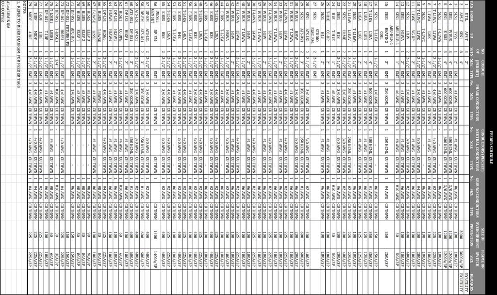
4 4 I. Power Distribution Systems Summary Description of Distribution System The electrical distribution system for Chandler City hall receives its power supply from Arizona Public Service, located in Phoenix, Arizona. Arizona Public Service owns all equipment and feeders through the service entrance up until the main switchboard. At this point the building voltage system is 480Y/277V, 3PH, 4W. Chandler City Hall s responsibility begins at the 3000A three-pole main switchboard which has an AIC rating of 65K which then serves other branch circuits of the electrical system. The building utilizes an uninterrupted power supply, (UPS,) and an emergency diesel generator to supply electricity in the case of a power outage or other failure. Automatic transfer switches are utilized to detect a lack of electricity. From the generator, power first flows through the emergency distribution panel to distribution panels DP-LS1 and DP-OS1 and then on the life safety loads of the building. Utility Company Information Arizona Public Services, located in Phoenix, Arizona is the utility company that supplies Chandler City Hall. Arizona Public Service 400 N. 5 th St. Phoenix, AZ For commercial buildings APS electric plan has three components 1. A monthly service charge a basic service fee that is the same each month 2. A demand charge based on your peak kilowatt demand for the month 3. An energy charge based on your kilowatt-hour usage for the month The rate schedule is as follows: E-32 Medium Basic Service Charge Self-Contained Meters Instrument-Rated Meters Primary Voltage Transmission Voltage $ per day $1.324 per day $ per day $ per day Energy Charge May October Billing Cycles (Summer) November - April Billing Cycles (Winter) $ per kwh for the first 200 kwh, plus $ per kwh for the first 200 kwh, plus $ per kwh for all additional kwh $ per kwh for all additional kwh
5 5 Demand Charge Secondary Service: $9.597 per kw for the first 100 kw, plus $5.105 per kw for all addtional kw Primary Service: $8.905 per kw for the first 100 kw, plus $4.412 per kw for all addtional kw Transmission Service: $6.942 per kw for the first 100 kw, plus $2.450 per kw for all addtional kw Note: Chandler City Hall is currently under construction therefore Electric Utility Load Data for the previous 12 months is not available. Service Entrance APS primary conductors run along Washington St. and enter the east side of the site into the utility yard. The primary voltage is not listed in the construction drawings or specifications. The primary conductors however run to the APS owned pad mounted transformer and are stepped down to a 480Y/277V, 3PH, 4W system. Still owned by APS, these secondary conductors run from the transformer into the building to the main switchboard and are metered by APS equipment. The service entrance feeder is routed into the building into room SES to the main switchboard SES#1. The following electrical components are owned by Arizona Public Service: Primary conductors APS Pad-mounted transformer Secondary Conductors APS Switching Cabinets APS Capacitor Bank Chandler City Hall s responsibility of electrical equipment begins at the main switchboards. Voltage Systems Primary Service: N/A; owned and supplied by Arizona Public Services Secondary Feeder: 480Y/277V, 3 PH, 4W Main switchboard SES#1 : 480Y/277V, 3 PH, 4W Electrical and Lighting Load Panels: HVAC Loads: 480Y/277V, 3 PH, 4W Lighting Loads: 480Y/277V, 3 PH, 4W Receptacle Loads: 208Y/120V, 3PH, 4W Council Chamber/Vision Center Dimming Panels: 208Y/120V, 3PH, 4W Emergency Power System(s) In terms of emergency power systems, a 750kW, kva, 480Y/277V, 3PH, 4W emergency diesel generator is located in the utility yard. This is activated by an automatic transfer switch to supply the
6 6 life safety loads for the building via a distribution panel. Emergency lighting, security, fire alarm, specified receptacles, and elevator motors are serviced by the emergency panels. Locations of Switchgear The main switchgear SES#1 is located on the first floor in Area B, room B135 of electrical plan NE Two 1200A 480V, 3PH, 4W bus ducts are fed from this equipment; one running vertically up through the west side of the building feeding electrical rooms A212, A312, A411, and A516 and the other vertically up through the east side of the building feeding electrical rooms A220, A319, A419, and A525. The automatic transfer switches ATS-LS1 and ATS-OS1 are also located on the first floor in Area B electrical room, room B132 of electrical plan NE Both Level 1 Area A and Area B of Chandler City Hall have electrical rooms where the majority of the lighting and receptacle load panels exist. Additionally on the west side, Area B of Level 1 electrical lighting room where the majority of the lighting panels reside. There are electrical rooms on each the east and west side of the upper floors as well as mechanical rooms. Major Equipment Schedule Tag Type Floor Room # Room Name 1/8" Scale Drawing Enlarged Drawing SES#1 Main Switchboard 1 B135 SES NE2.1.2 N/A DP-EM Emergency Distribution Panel 1 B132 ELEC NE2.1.2 N/A DP-LS1 Distribution Panel 1 B132 ELEC NE2.1.2 N/A DP-OS1 Distribution Panel 1 B132 ELEC NE2.1.2 N/A T-L1WA Transformer 1 A121 ELEC NE2.1.1 N/A T-L1WC Transformer 1 A121 ELEC NE2.1.1 N/A T-L1EA Transformer 1 B132 ELEC NE2.1.2 N/A T-L1EAV Transformer 1 B132 ELEC NE2.1.2 N/A T-H1E Transformer 1 B129 ELEC/LTG NE2.1.2 N/A T-L2WA Transformer 2 A212 ELEC NE2.2.1 N/A T-L2EA Transformer 2 A220 ELEC NE2.2.1 N/A T-L3WA Transformer 3 A312 ELEC NE2.3.1 N/A T-L3EA Transformer 3 A319 ELEC NE2.3.1 N/A T-L4WA Transformer 4 A411 ELEC NE2.4.1 N/A T-L4EA Transformer 4 A419 ELEC NE2.4.1 N/A T-L5WA Transformer 5 A516 ELEC NE2.5.1 N/A T-L5EA Transformer 5 A525 ELEC NE2.5.1 N/A T-LOSE1 Transformer 1 B132 ELEC NE2.1.2 N/A T-IDF Transformer 1 B132 ELEC NE2.1.2 N/A T-LW5E Transformer 5 A525 ELEC NE2.5.1 N/A Generator Generator 1 UTILITY YARD NE2.1.2 N/A UPS UPS 1 B124 DATA NE2.1.2 N/A ATS-LS1 Automatic Transfer Switch 1 B132 ELEC NE2.1.2 N/A ATS-OS1 Automatic Transfer Switch 1 B132 ELEC NE2.1.2 N/A
7 7 PANELBOARD SCHEDULE Tag Voltage System Main Size Floor Room # Room Name 1/8" Scale Drawing H1W 480Y/277V, 3PH, 4W 400A 1 A121 ELEC NE2.1.1 H1WA 480Y/277V, 3PH, 4W 100A 1 A121 ELEC NE2.1.1 L1WA 208Y/120V, 3PH, 4W 225A 1 A121 ELEC NE2.1.1 L1WC 208Y/120V, 3PH, 4W 225A 1 A104 MULTI. NE2.1.1 VG-DP 208Y/120V, 3PH, 4W 125A 1 A102 STORAGE NE2.1.1 CC-DP 208Y/120V, 3PH, 4W 175A 1 B129 ELEC/LTG NE2.1.2 H1E 480Y/277V, 3PH, 4W 225A 1 B129 ELEC/LTG NE2.1.2 H1ME 480Y/277V, 3PH, 4W 400A 1 B132 ELEC NE2.1.2 L1EA 208Y/120V, 3PH, 4W 350A 1 B132 ELEC NE2.1.2 L1EB 208Y/120V, 3PH, 4W 225A 1 B132 ELEC NE2.1.2 L1EC 208Y/120V, 3PH, 4W 225A 1 B132 ELEC NE2.1.2 L1EAV 208Y/120V, 3PH, 4W 225A 1 B132 ELEC NE2.1.2 H1S 480Y/277V, 3PH, 4W 100A 1 B132 ELEC NE2.1.2 LOSE1 208Y/120V, 3PH, 4W 50A 1 B132 ELEC NE2.1.2 HOSE1 480Y/277V, 3PH, 4W 225A 1 B132 ELEC NE IDF 208Y/120V, 3PH, 4W 200A 1 B132 ELEC NE2.1.2 HLSE1 208Y/120V, 3PH, 4W 100A 1 B132 ELEC NE2.1.2 LMK 208Y/120V, 3PH, 4W 100A MEZZ. M107 STORAGE NE2.1.3 HMW 480Y/277V, 3PH, 4W 225A MEZZ. M111 STORAGE NE2.1.3 HLSW1 480Y/277V, 3PH, 4W 225A MEZZ. M111 STORAGE NE2.1.3 MIDF 208Y/120V, 3PH, 4W 200A MEZZ. M111 STORAGE NE2.1.3 H2E 480Y/277V, 3PH, 4W 400A 2 A220 ELEC NE2.2.1 H2W 480Y/277V, 3PH, 4W 100A 2 A212 ELEC NE2.2.1 L2EA 208Y/120V, 3PH, 4W 225A 2 A220 ELEC NE2.2.1 L2WA 208Y/120V, 3PH, 4W 225A 2 A212 ELEC NE2.2.1 H3E 480Y/277V, 3PH, 4W 400A 3 A319 ELEC NE2.3.1 H3W 480Y/277V, 3PH, 4W 100A 3 A312 ELEC NE2.3.1 L3EA 208Y/120V, 3PH, 4W 225A 3 A319 ELEC NE2.3.1 L3WA 208Y/120V, 3PH, 4W 225A 3 A312 ELEC NE2.3.1 H4E 480Y/277V, 3PH, 4W 400A 4 A419 ELEC NE2.4.1 H4W 480Y/277V, 3PH, 4W 100A 4 A411 ELEC NE2.4.1 L4EA 208Y/120V, 3PH, 4W 225A 4 A419 ELEC NE2.4.1 L4WA 208Y/120V, 3PH, 4W 225A 4 A411 ELEC NE IDF 208Y/120V, 3PH, 4W 200A 4 A411 ELEC NE2.4.1 HLSW4 480Y/277V, 3PH, 4W 225A 4 A411 ELEC NE2.4.1 H5E 480Y/277V, 3PH, 4W 400A 5 A525 ELEC NE2.5.1 H5W 480Y/277V, 3PH, 4W 100A 5 A516 ELEC NE2.5.1 L5EA 208Y/120V, 3PH, 4W 225A 5 A525 ELEC NE2.5.1
8 8 PANELBOARD SCHEDULE CONTINUED Tag Voltage System Main Size Floor Room # Room Name 1/8" Scale Drawing L5WA 208Y/120V, 3PH, 4W 225A 5 A516 ELEC NE2.5.1 H5WA 480Y/277V, 3PH, 4W 400A 5 A516 ELEC NE2.5.1 L5WC 208Y/120V, 3PH, 4W 100A 5 A516 ELEC NE2.5.1 HLSE5 480Y/277V, 3PH, 4W 225A 5 A525 ELEC NE2.5.1 LLSE5 208Y/120V, 3PH, 4W 50A 5 A525 ELEC NE2.5.1 Over-current Devices From the service entrance, the main switchboard SES#1 is protected via the 3000A 3P main circuit breaker (MCB) with an AIC rating of 65K. The branch over-current devices within the switchboard range from 50A to 1200A and are all three-pole devices before serving the respective panelboards or transformers. The emergency generator has a 1400A three-pole circuit breaker. The distribution panels DP-EM, DP-LS1, and DP-OS1 are rated with a 1600A, 400A and 600A three-pole circuit breaker respectively with each of the distribution panels having an AIC rating of 42K. Two 1200A bus ducts feed the branch circuit of the upper floors of the building. Each of these branch circuits are protected via fuses. Class RK1, current-limiting, time-delay fuses are generally utilized with Class RK5 current-limiting, time-delay fuses used where the amperage ratio between the panelboard main fuse to the largest feeder fuse is at least 2:1 and for motor starter size 3 or smaller. The fuse protection ratings within the branch circuit range from 100A to 400A, all three-pole devices.. Transformers Chandler City Hall s electrical distribution system utilizes 16 dry-type transformers. Each is located within an electrical room on the respective floor of the panels which it services and steps down the voltage from 480Y/277V, 3PH, 3W to 208Y/120V, 3PH, 4W. Transformer Schedule TAG Primary Voltage Secondary Voltage Size Type Temp. Rise T-L4EA 480Y/277V, 3PH, 3W 208Y/120V, 3PH, 4W 75 DRY 115 C (4) 2.5% Pad-Mounted Taps Mounting T-L1WA 480Y/277V, 3PH, 3W 208Y/120V, 3PH, 4W 75 DRY 115 C (4) 2.5% Pad-Mounted T-L1WC 480Y/277V, 3PH, 3W 208Y/120V, 3PH, 4W 75 DRY 115 C (4) 2.5% Pad-Mounted T-L1EA 480Y/277V, 3PH, 3W 208Y/120V, 3PH, 4W DRY 115 C (4) 2.5% Suspended T-L1EAV 480Y/277V, 3PH, 3W 208Y/120V, 3PH, 4W 75 DRY 115 C (4) 2.5% Pad-Mounted T-H1E 480Y/277V, 3PH, 3W 208Y/120V, 3PH, 4W 30 DRY 115 C (4) 2.5% Pad-Mounted T-L2WA 480Y/277V, 3PH, 3W 208Y/120V, 3PH, 4W 75 DRY 115 C (4) 2.5% Pad-Mounted T-L2EA 480Y/277V, 3PH, 3W 208Y/120V, 3PH, 4W 75 DRY 115 C (4) 2.5% Pad-Mounted T-L3WA 480Y/277V, 3PH, 3W 208Y/120V, 3PH, 4W 75 DRY 115 C (4) 2.5% Pad-Mounted T-L3EA 480Y/277V, 3PH, 3W 208Y/120V, 3PH, 4W 75 DRY 115 C (4) 2.5% Pad-Mounted T-L4WA 480Y/277V, 3PH, 3W 208Y/120V, 3PH, 4W 75 DRY 115 C (4) 2.5% Pad-Mounted
9 9 Transformer Schedule Continued TAG Primary Voltage Secondary Voltage Size Type Temp. Rise Taps Mounting T-L5WA 480Y/277V, 3PH, 3W 208Y/120V, 3PH, 4W 75 DRY 115 C (4) 2.5% Pad-Mounted T-L5EA 480Y/277V, 3PH, 3W 208Y/120V, 3PH, 4W 75 DRY 115 C (4) 2.5% Pad-Mounted T-LOSE1 480Y/277V, 3PH, 3W 208Y/120V, 3PH, 4W 15 DRY 115 C (2) 2.5% Pad-Mounted T-IDF 480Y/277V, 3PH, 3W 208Y/120V, 3PH, 4W 75 DRY 115 C (4) 2.5% Pad-Mounted T-LW5E 480Y/277V, 3PH, 3W 208Y/120V, 3PH, 4W 30 DRY 115 C (4) 2.5% Pad-Mounted Grounding As shown to its extent, the grounding system in the electrical one-line diagrams E7.1-E7.3. The main neutral is bonded to the main ground bar at the service entrance to the grounding electrodes. The main ground bar is also shown connected to the building steel and cold water piping within the building. Special Equipment An 80kVA uninterrupted power supply is utilized by Chandler City Hall. It is energized by automatic transfer switch ATS-OS1 and feeds distribution panel DP-OS1. The UPS is located in Data Room B134 right next to Electrical Room B132 where ATS-OS1 and DP-OS1 are located. Harmonic filtering is specified at a maximum value of 10% THD at 100% non-linear loading and the batteries are to provide 100% power for 15 minutes in this system. Other components that would fall into the category of special equipment within Chandler City Hall include the diesel generator that was previously discussed in Emergency Power Systems. Lighting Loads Keeping energy efficiency in mind, Chandler City Hall has created a lighting design solution reinforcing its architectural concepts from the outside in. A range of sources including fluorescent, metal halide, halogen, and led sources are used in the lighting design of Chandler City Hall. Typical lighting loads are serviced by a 480Y/277V system. However the lighting in the Council Chamber and Vision Gallery utilize power from the 208Y/120V system. With complex lighting and control systems both of these spaces the lower voltage is used as they are fed from dimming panels. There are programmable controls for these spaces in order to have appropriate lighting scheme for a particular event that may occur. The following luminaire schedule depicts the specified luminaires in more detail below. Luminaire Schedule Tag Light Source Lamp Type Individual Lamp Wattage No. of Lamps AC QUAR 35 W MR16 35 W 1 ACB QUAR 35 W MR16 35 W 1 Ballast Type Operating or Input Voltage Fixture Input Watts Ballast Factor Start/ Operating Power Factor@ Start/ Operating INTEGRAL XFMR 277 V 35 W INTEGRAL XFMR 120 V 35 W
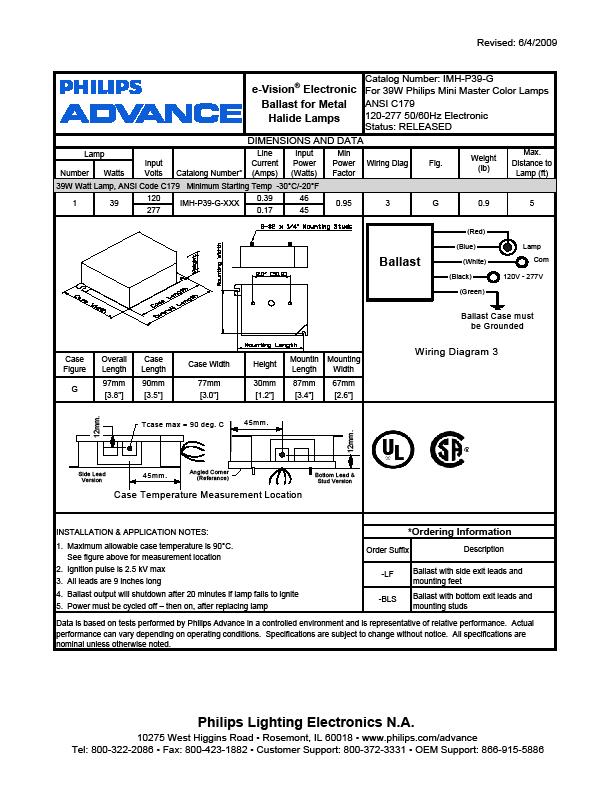
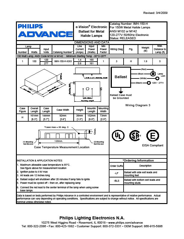
10 10 Luminaire Schedule Tag Light Source Lamp Type Individual Lamp Watt No. of Lamps Ballast Type Operating or Input Voltage Fixture Input Watts Ballast Factor Start/ Operating Power Factor@ Start/ Operating BL FLUOR 24 W T5HO 24 W 1 ELECTRONIC 277 V 27 W CH FLUOR 28 W T5 28 W 2 ELECTRONIC 277 V 58 W CR FLUOR 54 W T5HO 54 W 4 ELECTRONIC 277 V 234 W CY FLUOR 32 W TRT 32 W 1 ELECTRONIC 277 V 38 W F1 FLUOR 32 W TRT 32 W 1 ELECTRONIC 120 V 36 W F2 FLUOR 32 W TRT 32 W 1 ELECTRONIC 277 V 38 W F2 EM FLUOR 32 W TRT 32 W 1 ELECTRONIC 277 V 38 W F3 FLUOR 32 W TRT 32 W 1 ELECTRONIC 277 V 38 W F4 FLUOR 26 W TRT 26 W 1 ELECTRONIC 277 V 31 W F5 FLUOR 26 W TRT 26 W 1 ELECTRONIC 277 V 31 W F6 FLUOR 42 W TRT 42 W 1 ELECTRONIC 120 V 46 W /1. F7 FLUOR 54 W T5HO 54 W 1 ELECTRONIC 120 V W/ DIMMING W F9 FLUOR 24 W T5HO 24 W 1 ELECTRONIC DIMMING F10 FLUOR 17 W T8 17 W 1 ELECTRONIC DIMMING 277 V 27 W V 7 W/24 W 0.05/ F11 FLUOR 32 W TRT 32 W 1 ELECTRONIC 277 V 38 W F11 EM FLUOR 32 W TRT 32 W 1 ELECTRONIC 277 V 38 W F12 FLUOR 32 W T8 32 W 1 ELECTRONIC 277 V 34 W F13 FLUOR 54 W T5HO 54 W 1 ELECTRONIC 277 V 62 W F14 FLUOR 55 W TBX 55 W /0. ELECTRONIC 120 V W/ DIMMING W W/ /1. F15 FLUOR 54 W T5HO 54 W ELECTRONIC V W DIMMING 39 W T5HO 39 W 43 W W T5HO 24 W 27 W FD FLUOR 32 W TRT 32 W 1 ELECTRONIC 277 V 38 W H1 MH 35 W T6 35 W 1 PULSE START 277 V 45 W H2 MH 39 W T6 39 W 2 PULSE START 277 V 45 W H4 MH 39 W T6 39 W 1 PULSE START 277 V 45 W H4A MH 39 W T6 39 W 1 PULSE START 277 V 45 W H4AE MH 39 W T6 39 W 1 PULSE START 277 V 45 W H4E MH 39 W T6 39 W 1 PULSE START 277 V 45 W H5 MH 70 W T6 70 W 1 PULSE START 277 V 79 W
11 11 Luminaire Schedule Continued Tag PGP PGP2 Light Source LED LED Lamp Type Individual Lamp Wattage Number of Lamps Ballast Type Operating or Input Voltage Fixture Input Watts Ballast Factor Start/ Operating Power Factor@ Start/ Operating INTEGRAL LED 104 W N/A 277 V 104 W INTEGRAL LED 104 W N/A 277 V 104 W RF FLUOR 54 W T5HO 54 W 1 ELECTRONIC 277 V 62 W RF2 FLUOR 54 W T5HO 54 W 1 ELECTRONIC 277 V 62 W RF3 FLUOR 26 W TRT 26 W 1 ELECTRONIC 277 V 31 W SA FLUOR 54 W T5HO 54 W 2 ELECTRONIC 277 V 117 W SB FLUOR 54 W T5HO 54 W 1 ELECTRONIC 277 V 62 W SG FLUOR 32 W T8 32 W 2 ELECTRONIC 277 V 63 W SG EM FLUOR 32 W T8 32 W 2 ELECTRONIC 277 V 63 W SH FLUOR 32 W T8 32 W 1 ELECTRONIC 277 V 34 W T FLUOR 24 W T5HO 24 W 2 ELECTRONIC 277 V 52 W T1 QUAR 90 W PAR38HIR NFL 90 W 10 N/A 120 V 900 W T2 QUAR 200 W PAR38HIR WFL 200 W 1 N/A 120 V 200 W T3 QUAR 100 W PAR38HIR SP W 1 N/A 120 V 100 W T4 QUAR 100 W PAR38HIR SP W 1 N/A 120 V 100 W T5 QUAR 100 W PAR38HIR NFL W 1 N/A 120 V 100 W T6 QUAR 100 W PAR38HIR NFL W 1 N/A 120 V 100 W T7 QUAR 100 W PAR38HIR NFL W 1 N/A 120 V 100 W T7A QUAR 100 W PAR38HIR NL W 1 N/A 120 V 100 W TK QUAR 35 W MR16 35 W 1 N/A 277 V 35 W TR QUAR 37 W MR16HIR CG25 37 W 3 N/A 277 V 120 W TZ FLUOR 28 W T5 28 W 2 ELECTRONIC 277 V 58 W UC FLUOR 32 W T8 32 W 1 ELECTRONIC 120 V 34 W VT FLUOR 32 W T8 32 W 2 ELECTRONIC 277 V 63 W VT8 FLUOR 32 W T8 32 W 4 ELECTRONIC 277 V 121 W Z1 QUAR 60 W T4 60 W 1 N/A 120 V 60 W
12 12 Lighting Control Lighting within Chandler City Hall makes use of several different control systems. In the open office spaces in the tower, a daylight harvesting system is used to control and dim the linear fluorescent lighting system. In order to meet ASHRAE/IESNA90.1 standards, two dimming control panels are used in Chandler City Hall. These serve the purpose of controlling the lighting for the Council Chamber and the Vision Gallery. These spaces have numerous luminaires with several settings that are dependent upon the event that will be occurring. There will never be an incident where all the luminaires will be on within these spaces. Mechanical and Other Loads Utilizing a combination of variable air volume and constant volume systems air is circulated throughout Chandler City Hall. A total of thirteen air handling units are used between the north and south buildings of Chandler City Hall. Supplied by a chiller and cooling tower on the south building and parking garage a hydronic system supplies cool air to the building which is distributed by a variable air volume system as the main distribution with a constant air volume as the secondary distribution system for use in only a few spaces within Chandler City Hall. As only one service entrance is being evaluated, only the mechanical equipment on that service entrance is evaluated below. *Note: Tables will be adjusted in Final report to show the headings on each page split Mechanical Equipment Schedule Tag Description Load Mag./Units NEC Motor Amps Voltage Ph Assumed Power Factor Equivalent Load (kva)/ (kw) AHU-1-1 AIR HANDLING UNIT 7.5 HP AHU-A-2-1 AIR HANDLING UNIT 15 HP AHU-A-2-2 AIR HANDLING UNIT 15 HP AHU-A-3-1 AIR HANDLING UNIT 15 HP AHU-A-3-2 AIR HANDLING UNIT 15 HP AHU-A-4-1 AIR HANDLING UNIT 15 HP AHU-A-4-2 AIR HANDLING UNIT 15 HP AHU-A-5-1 AIR HANDLING UNIT 15 HP AHU-A-5-2 AIR HANDLING UNIT 15 HP AHU-A-M-1 AIR HANDLING UNIT 10 HP AHU-A-R-1 AIR HANDLING UNIT 20 HP HEATING COIL HEATING COIL 105 KW AHU-A-R-2 AIR HANDLING UNIT 15 HP HEATING COIL HEATING COIL 70 KW AHU-A-R-3 AIR HANDLING UNIT 20 HP AHU-A-LR-1 AIR HANDLING UNIT 20 HP AHU-B-LR-1 AIR HANDLING UNIT 20 HP TOTAL (kw) 975.4
13 13 Mechanical Equipment Schedule Continued Tag Description Load Mag./Units NEC Motor Amps Voltage Ph Assumed Power Factor Equivalent Load (kva)/ (kw) HEATING COIL HEATING COIL 150 KW AHU-B-LR-2 AIR HANDLING UNIT 15 HP AHU-B-LR-3 AIR HANDLING UNIT 15 HP HEATING COIL HEATING COIL 55 KW PK-A-R-1 PACKAGED A/C UNITS 7.5 KW PK-A-R-2 PACKAGED A/C UNITS 5.4 KW CRAC-A-1-1 COMPUTER ROOM A/C UNITS 7.5 HP CRAC-A-1-2 COMPUTER ROOM A/C UNITS 7.5 HP TU-A TERMINAL UNITS 2 KW TU-B TERMINAL UNITS 3 KW TU-C TERMINAL UNITS 4 KW TU-D TERMINAL UNITS 4.75 KW TU-E TERMINAL UNITS 6.5 KW TU-F TERMINAL UNITS 10 KW TU-G TERMINAL UNITS 12 KW TU-H TERMINAL UNITS 3 KW TU-J TERMINAL UNITS 4.5 KW FCU-A-1-1 FAN COIL UNIT 0.07 KW FCU-A-1-2 FAN COIL UNIT 0.07 KW FCU-A-M-1 FAN COIL UNIT 0.07 KW FCU-A-M-2 FAN COIL UNIT 0.07 KW FCU-A-2-1 FAN COIL UNIT 0.07 KW FCU-A-2-2 FAN COIL UNIT 0.07 KW FCU-A-2-3 FAN COIL UNIT 0.07 KW FCU-A-2-4 FAN COIL UNIT 0.07 KW FCU-A-3-1 FAN COIL UNIT 0.07 KW FCU-A-3-2 FAN COIL UNIT 0.07 KW FCU-A-3-3 FAN COIL UNIT 0.07 KW FCU-A-3-4 FAN COIL UNIT 0.07 KW FCU-A-4-1 FAN COIL UNIT 0.07 KW FCU-A-4-2 FAN COIL UNIT 0.07 KW FCU-A-4-3 FAN COIL UNIT 0.07 KW FCU-A-5-1 FAN COIL UNIT 0.07 KW
14 14 Mechanical Equipment Schedule Continued Tag Description Load Mag./Units NEC Motor Amps Voltage Ph Assumed Power Factor Equivalent Load (kva)/ (kw) FCU-A-5-2 FAN COIL UNIT 0.07 KW FCU-A-5-3 FAN COIL UNIT 0.07 KW FCU-A-5-4 FAN COIL UNIT 0.07 KW FCU-A-1-5 FAN COIL UNIT 0.09 KW FCU-B-1-2 FAN COIL UNIT 0.12 KW FCU-B-1-3 FAN COIL UNIT 0.12 KW FCU-B-1-4 FAN COIL UNIT 0.12 KW FCU-A-1-3 FAN COIL UNIT KW FCU-A-1-4 FAN COIL UNIT KW FCU-B-1-1 FAN COIL UNIT 1.4 KW FCU-B-1-5 FAN COIL UNIT 1.7 KW CU-A-R-1 OUTDOOR UNIT 15.8 KW KW CU-A-R-2 OUTDOOR UNIT 14.2 KW KW CU-A-LR-1 OUTDOOR UNIT 14.2 KW KW CU-B-R-1 OUTDOOR UNIT 20.8 KW KW PT 0.08 CONTROL 10PT CONTROL EUH-A-5-1 EUH-A-5-2 EUH-A-5-3 EUH-A-5-4 EUH-A-5-5 EUH-A-5-6 FCU-A-5-1 CONTROLLER 6 KW CONTROLLER 8 KW ELECTRIC UNIT HEATER 3 KW ELECTRIC UNIT HEATER 3 KW ELECTRIC UNIT HEATER 3 KW ELECTRIC UNIT HEATER 3 KW ELECTRIC UNIT HEATER 3 KW ELECTRIC UNIT HEATER 3 KW CHILLED WATER FAN COIL UNIT 2 KW
15 15 Mechanical Equipment Schedule Continued Tag Description Load Mag./Units NEC Motor Amps Voltage Ph Assumed Power Factor Equivalent Load (kva)/ (kw) EHC-A-M-1 ELECTRIC HEATING COIL 80 KW EF-A-1-1 EXHAUST FAN KW EF-A-LR-1 EXHAUST FAN KW EF-A-R-1 EXHAUST FAN 7.5 HP EF-A-5-1 EXHAUST FAN KW EF-A-5-2 EXHAUST FAN KW EF-A-5-3 EXHAUST FAN KW EF-B-LR-1 EXHAUST FAN 0.5 HP TOTAL (kw) Plumbing Equipment Schedule Tag Description Load Mag/Units NEC Motor Amps Voltage Phase Assumed Power Factor Equivalent Load (kva)/(kw) EWH-A-1-1 WATER HEATER 24 KW EWH-A-1-2 WATER HEATER 24 KW EWH-A-M-1 WATER HEATER 24 KW EWH-A-2-1 WATER HEATER 24 KW EWH-A-3-1 WATER HEATER 24 KW EWH-A-4-1 WATER HEATER 24 KW EWH-A-5-1 WATER HEATER 24 KW EWH-A-1-3 WATER HEATER 18 KW EWH-A-1-4 WATER HEATER 18 KW EWH-A-1-5 WATER HEATER 18 KW EWH-A-2-2 WATER HEATER 18 KW EWH-A-2-3 WATER HEATER 18 KW EWH-A-2-4 WATER HEATER 18 KW EWH-A-3-2 WATER HEATER 18 KW EWH-A-3-3 WATER HEATER 18 KW EWH-A-3-4 WATER HEATER 18 KW EWH-A-4-2 WATER HEATER 18 KW EWH-A-4-3 WATER HEATER 18 KW EWH-A-4-4 WATER HEATER 18 KW
16 16 Plumbing Equipment Schedule Continued Tag Description Load Mag/Units NEC Motor Amps Voltage Phase Assumed Power Factor Equivalent Load (kva)/(kw) EWH-A-5-2 WATER HEATER 18 KW EWH-A-5-3 WATER HEATER 18 KW EWH-A-5-4 WATER HEATER 18 KW EWH-A-M-3 WATER HEATER 18 KW EWH-A-M-2 WATER HEATER 6.5 KW EWH-A-5-5 WATER HEATER 6.5 KW EWH-B-1-1 WATER HEATER 24 KW EWH-B-1-2 WATER HEATER 18 KW EWH-B-1-3 WATER HEATER 6.5 KW DWP WATER PUMP 5 HP TOTAL (kw) Architectural Equipment Schedule Tag Elevator 1 Elevator 2 Elevator 3 Description Load Mag/Units NEC Motor Amps Voltage Phases Assumed Power Factor Equivalent Load (kva)/ (kw) ELECTRIC TRACTION ELEVATOR 25 HP ELECTRIC TRACTION ELEVATOR 25 HP ELECTRIC TRACTION ELEVATOR 30 HP TOTAL (kw) 83.6 Service Entrance Size The following is an analysis summary to size the service entrance. Calculations were performed for the three phases of design: Conceptual/Schematic Design, Design Development, and Working Drawings. The first method uses building areas and a demand load in VA/Sq.Ft. which is associated with the building/occupancy type of which office building was used for the analysis of Chandler City Hall. The second method used is based on NEC building load values and demand factors applied across the appropriate areas of the building. The last method, associated with the final phases of design, is based off the actual loading as indicated on the panelboards from the construction documents. The service entrance size was then computed for each of the analyses; the calculations for each method are shown below:
17 17 Conceptual/Schematic Phase: Load per Sq. Ft. Building Area VA/sq.ft. VA Type (sq.ft.) Office Total KVA: Load- Amps: Service Entracne Size: 2000A Design Development: NEC Loading Load Type Area (sq.ft.) VA/sq.ft. Demand Factor KVA Lighting Receptacles Fans and Pumps HVAC Equipment: Electric Heating Plumbing Equipment: Electric Water Heaters (14) 60kW/heater Architectural Equipment: Elevators (3) 50kW/elev Total KVA: 3002 Load- Amps: Service Entracne Size: 4000A Working Drawings: Actual Loading Load Type Connected Load (kva) Demand Factor Demand Load (kva) Lighting Receptacles Fans and Pumps HVAC Equipment: Plumbing Equipment: Architectural Equipment: Total Demand KVA: Load-Amps: Service Entrance Size: 3000A
18 18 Summary Tables Table 1 Load - kva Voltage System Phase Load - Amps Conceptual/Schematic Design /277V Design Development /277V Working Drawings /277V Actual Conditions /277V 2835 Table 2 Service Entrance Size - Amps Voltage System Capacity - kva Actual Conditions 3000A 480/277V 2493 Summary VA/sq.ft VA/sq.ft. The resulting service entrance size for the conceptual/schematic phase is likely undersized due to the actual mixed use occupancy of the building. It is meant to accommodate a variety of different events as well as the loads from a typical office space. As for the design development phase, the service entrance size is oversized. This however is likely due to the demand of the electric heating component. This is the peak demand over the cooling load, however the building is located in Chandler, Arizona, a rather warm climate where the heating actual heating loads are less than the estimated values computed in the design development phase. The working drawings phase proves to be the most accurate in computing the service entrance size as to what has been computed by the engineers on the project for the sizing of the service entrance for Chandler City Hall. Environmental Stewardship Design Environmental consideration was of high importance in the design of Chandler City Hall. As the building is currently still under construction, it is striving to achieve a LEED gold rating upon completion. A photovoltaic system was considered, but not implemented into the design. Future additional open panels were supplied in the event that a photovoltaic system is implemented. Although not clearly defined, Chandler City Hall in various ways has aimed to create an electrical building system and lighting system that portrays energy efficiency with minimal building loads where appropriate. Design Issues Although not in the current design, Chandler City Hall s electrical distribution system has left room for the potential future design of a photovoltaic system. The photovoltaic system would be located across the street on the top floor of the parking garage and enter the site as a separate service entrance to Chandler City Hall.
19 19 II. Communication Systems Additional systems that run into Chandler City Hall include voice/data, and cable. The building is equipped with audiovisual capabilities in many of its areas but is particularly important in the Council Chambers where a variety of different events could potentially occur. These capabilities are also fed to office conference rooms and the mayor s conference space. III. Security Systems Chandler City Hall has a security system in which surveillance cameras have been installed within several of the corridor and publically accessible spaces. Additionally, for more high security areas, doors are equipped with card readers on accessible to specific personnel. IV. Fire Protection Systems Vital to life safety, Chandler City Hall has a fire protection plan that is laid out through the spaces of Chandler City Hall. Coordinated with all other building systems, a piping system coupled with sprinklers services all spaces within the buildings.
20 20 V. Appendix A Please refer to inserted drawings.
21
22
23
24 24 VI. Appendix B
25 25
26 26
27 27
28 28
29 29
30 30
Building Electrical System Overview
 Philip Mackey L/E Dr. Mistrick Holy Cross Hospital North Addition Silver Spring, MD 0/3/05 Building Electrical System Overview Executive Summary: The following report describes the existing emergency power
Executive Summary. CNBC Global Headquarters Christine Cajilig
 Executive Summary This report contains an analysis and description of the existing electrical distribution of the including the distribution type, emergency power, uninterruptible power system, over current
Technical II Report Electrical Systems
 Technical II Report Electrical Systems Kelly Chan Consultant: Prof T. Dannerth, P.E. Part A Drawings Drawings needed for single-line diagram EE1.01 title sheet (electrical drawings) EE2.09 penthouse/roof
Technical Report #2. Newseum and Freedom Forum Headquarters. Washington, D.C. Ryan Wise Lighting/Electrical Prof. Dannerth November 2, 2007
 Technical Report #2 Ryan Wise Lighting/Electrical Prof. Dannerth November 2, 2007 Newseum and Freedom Forum Headquarters Washington, D.C. Table of Contents Power Distribution Systems Executive Summary
Lindsay Frederick. Lighting + Electrical. Ron Dodson Faculty Advisor. Native American Cultural Center Arizona. Technical Report 2
 Lindsay Frederick Lighting + Electrical Ron Dodson Faculty Advisor Native American Cultural Center Arizona Technical Report 2 Native American Cultural Center Technical Report 2 p. 2 Executive Summary The
ELECTRICAL EXISTING CONDITIONS AND DESIGN ANALYSIS
 Executive Summary ELECTRICAL EXISTING CONDITIONS AND DESIGN ANALYSIS Sara Lappano Ltg./Elec. Corron Cultural Center Middletown, VA Faculty Advisor: Dr. Moeck 11.4.2002 As in the prior lighting technical
Corbin Building. Technical Assignment 2. Matthew Trethaway Lighting/ Electrical AE 481W 10/26/2011 Advisor: Ted Dannerth
 Corbin Building Technical Assignment 2 Matthew Trethaway Lighting/ Electrical AE 481W 10/26/2011 Advisor: Ted Dannerth 10/26/2011 Technical Report II 1 Executive Summary The following report is an overview
Lord Stirling Community School Electrical Systems Existing Conditions & Building Load Summary Technical Assingment#2 Due October 26, 2004
 Electrical Systems Existing Conditions & Building Load Summary Technical Assingment#2 Due October 26, 2004 Table of Content: Page 1 ~ Single Line Diagram 1 2 ~ Electrical System Narrative 2-3 3 ~ Lamp
Brown University Revised June 29, 2012 Facilities Design & Construction Standards SECTION ELECTRICAL DESIGN CRITERIA
 PART 1 - GENERAL 1.1 Background SECTION 26 00 10- ELECTRICAL DESIGN CRITERIA A. Brown University maintains it own campus electrical distribution system which serves the majority of the buildings and facilities
Technical Report Two
 Technical Report Two Yale Sculpture Building Advisors: Ted Dannerth Richard Mistrick Date: October 31, 2006 Electrical Systems Existing Conditions and Building Load Summary Report Executive Summary: This
TONY ESPOSITO LIGHTING/ELECTRICAL TECHNICAL REPORT II SEPTEMBER 15, 2011 HUNTER S POINT SOUTH INTERMEDIATE SCHOOL AND HIGH SCHOOL QUEENS, NY
 LIGHTING/ELECTRICAL TECHNICAL REPORT II SEPTEMBER 15, 2011 HUNTER S POINT SOUTH INTERMEDIATE SCHOOL AND HIGH SCHOOL QUEENS, NY 1 1A. POWER DISTRIBUTION SYSTEMS a. EXECUTIVE SUMMARY b. SUMMARY DESCRIPTION
Technical Assignment #2 Electrical Systems Existing Conditions & Building Load Summary
 Technical Assignment #2 Electrical Systems Existing Conditions & Building Load Summary William H. Gates Hall Seattle, WA Katherine Jenkins Lighting/Electrical Option October 27, 2006 Faculty Advisor: Ted
Electrical Systems Existing Conditions and Building Load Summary Report
 The building was constructed a few years ago to act as both a Headquarters and to be a display of what the product they manufacture can accomplish when put to work. The building features both office and
Technical Report 2: Electrical Systems Criteria and Existing Conditions
 Technical Report 2: Electrical Systems Criteria and Existing Conditions Princeton Theological Seminary Library Princeton, NJ Stephanie Deckard Lighting Electrical Faculty Advisor Dr. Kevin Houser 10/12/2012
Chandler City Hall Chandler, Arizona
 Chandler City Hall Chandler, Arizona Thesis Proposal AE481W: Architectural Engineering Senior Thesis Friday December 10 th, 2010 Stephanie Romanias Lighting/Electrical Faculty Consultants: Dr. Kevin Houser
Division 26 ELECTRICAL TABLE OF CONTENTS
 Division 26 ELECTRICAL TABLE OF CONTENTS 26 1000 GENERAL... 33 A. CODE... 3 B. RELATED SECTIONS... 3 C. ABBREVIATIONS... 3 D. DEFINITIONS... 3 E. DRAWING REQUIREMENTS... 3 F. EQUIPMENT SERVICE ACCESS AND
Newark, Delaware Architectural Engineering Senior Thesis Portfolio. Electrical Analysis
 Electrical Analysis The AstroPower Headquarters building was constructed a few years ago to act as both a Headquarters and to be a display of what the product they manufacture can accomplish when put to
Electrical Design Guidelines Table of Contents
 C: Compliant Rev. 3 Dated June 13 11 NC: Non-Compliant NA: Not Applicable Page1 16.1 General 16.2 Single Line Diagrams 16.3 Electric Motor Equipment and Controls 16.4 Lighting 16.5 Emergency Lighting 16.6
Chang Liu Lighting + Electrical M.A.E./B.A.E. Integrated Degree. Technical Assignment 2 October 12, 2012 Faculty Consultants: Ron Dodson
 M.A.E./B.A.E. Integrated Degree Technical Assignment 2 October 12, 2012 Faculty Consultants: Ron Dodson Renzo Museum of American Art Executive Summary This report provides an analysis of the electrical
Technical Report 2: Electrical Systems Existing Conditions and Building Load Summary Report. 100% Submission. Sherrerd Hall, Princeton University, NJ
 Technical Report 2: Electrical Systems Existing Conditions and Building Load Summary Report 100% Submission Sherrerd Hall, Princeton University, NJ Faculty Consultant: Ted Dannerth 4 November 2009 Table
Electrical Systems Existing Conditions and Building Load Summary Broadway Plaza, Rochester, MN. Appendix A
 Appendix A Single Line Diagram Power Riser Diagram Dimming System Schematic Diagrams Dry-Type Transformer Schedule Primary Lamp and Ballast Table Mechanical Equipment Table Utility Rate Structure Breakdown
DESIGN AND CONSTRUCTION STANDARDS GENERAL DESIGN GUIDELINES
 2.07 ELECTRICAL GENERAL DESIGN AND CONSTRUCTION STANDARDS GENERAL DESIGN GUIDELINES - 2.07 It is expected that the electrical design professional will conform to accepted good engineering design practices.
Currently, all electrical upgrades would be voluntary, but there are situations in which upgrades would be required.
 Executive Summary The current electrical system is functional but requires some understanding in order to avoid overloading circuits. Certain outlets can be used for space heaters while others cannot and
Ho-Chunk Gaming THUNDERBIRD ENGINEERING, INC. MILWAUKEE: (414) MADISON: (608)
 MADISON: (608)") Ho-Chunk Gaming POWER SYMBOLS X ELECTRICAL PANEL - REFER TO DRAWINGS FOR WIDTH AND PANEL SCHEDULES PANEL NAMING: XXP-#X: DENOTES PANEL FUNCTION: L = LIGHTING P = GENERAL POWER E = EMERGENCY S = OPTIONAL
Ho-Chunk Gaming POWER SYMBOLS X ELECTRICAL PANEL - REFER TO DRAWINGS FOR WIDTH AND PANEL SCHEDULES PANEL NAMING: XXP-#X: DENOTES PANEL FUNCTION: L = LIGHTING P = GENERAL POWER E = EMERGENCY S = OPTIONAL
ELECTRIC SERVICE EVALUATIONS ELECTRICAL / BOILER REPLACEMENTS. Clarkstown Central School District. June Arch Proj. #
 ELECTRICAL ELECTRIC SERVICE EVALUATIONS / BOILER REPLACEMENTS Clarkstown Central School District June 2015 CSArch Arch Proj. # 151-1501.00 151 Table of Contents SECTION 1 Executive Summary... 1 SECTION
Computing Services Center
 Continuous Commissioning Report for the Computing Services Center Building #516 Submitted to: Utilities Energy Office Physical Plant Department Texas A&M University Prepared by: Energy Systems Laboratory
Electrical System (N) PANELBOARD "L1" VOLTAGE: 208/120 A, 3P :MAIN C/B PHASE: 3 A :BUSSING WIRE: 4 :MOUNTING
 PANELBOARD L1 VOLTAGE: 208/120 A, 3P :MAIN C/B PHASE: 3 A :BUSSING WIRE: 4 :MOUNTING") Electrical System After re-designing the lighting system for the children s computer, circulation and storytelling areas, the electrical system had to be redesigned as well. These are the new panel board
Electrical System After re-designing the lighting system for the children s computer, circulation and storytelling areas, the electrical system had to be redesigned as well. These are the new panel board
ELECTRICAL Seminar. B A L A Consulting Engineers, Inc. Edward J. Lynch, PE Vice President, Electrical Department Manager.
 B A L A Consulting Engineers, Inc. PECO Line 13.2kV Incoming Service No. 1 Utility/Generator Medium Voltage Switchgear PECO Line 13.2kV Incoming Service No. 2 Unit Substation ELECTRICAL Seminar HVAC Equip.
Senior Thesis Centre Community Hospital East Wing Addition - Proposal Keith Beidel Mechanical Option 12/05/02 1
 Table of Contents Page Number(s) Executive Summary 2 Project Background 3 Proposed Depth Alternatives 4 Proposed Depth Redesign 5-7 Justification of Proposed Depth Redesign 8 Proposed Breath Redesign 9
LIGHT LEVEL REQUIREMENTS MINIMUM ACCEPTABLE FOOT CANDLES
 LIGHT LEVEL REQUIREMENTS LOCATION Classrooms and instrumental areas- Study Halls, Lecture Rooms, Art Rooms, Offices, Libraries, Conference Rooms, Work Rooms, Shops, Laboratories and Secondary School Cafeterias.
MID MICHIGAN COMMUNITY COLLEGE HARRISON CAMPUS Harrison, Michigan 2015 MASTER PLAN
 MID MICHIGAN COMMUNITY COLLEGE HARRISON CAMPUS Harrison, Michigan 2015 MASTER PLAN September 30, 2015 PBA Project No. 2015.0140.00 PETER BASSO ASSOCIATES INC. CONSULTING ENGINEERS 5145 LIVERNOIS ROAD,
SECTION LIGHTING CONTROLS
 PART 1 - GENERAL 1.1 DESCRIPTION SECTION 26 09 23 LIGHTING CONTROLS SPEC WRITER NOTE: 1. Delete between //----// if not applicable to project. Also, delete any other item or paragraph not applicable to
Matt Cooper, PE, BEMP, HBDP, Group 14 Engineering Ken Urbanek, PE, HBDP MKK Consulting Engineers, Inc.
 M&V Real Results of High Performance Design Matt Cooper, PE, BEMP, HBDP, Group 14 Engineering Ken Urbanek, PE, HBDP MKK Consulting Engineers, Inc. Overview Measurement & Verification (M&V) Plan for New
Element D Services Electrical
 PART 1 - GENERAL 1.01 OVERVIEW A. This Section includes design standards and requirements for electrical service and distribution. This is a design standard and is not intended to be used as a Specification.
Franklin Square Hospital Center
 Franklin Square Hospital Center Baltimore, MD Thesis Proposal Cassandra Watson + Electrical Electrical Advisor Professor Dannerth Advisor Dr. Mistrick 16 December 2009 Table of Contents Executive Summary...
Renovate MCRC Facilities Great Lakes, IL
 6. ENGINEERING SYSTEMS REQUIREMENTS D50 ELECTRICAL SYSTEM DESCRIPTION The electrical repair work includes the design and construction of the electrical distribution system for the B3200 Marine Corps Reserve
Job Name Control Systems Description Date
 Job Name Control Systems Description Date Project Overview The project is a describe the building and its major HVAC systems (e.g. three-story office building, served by a rooftop unit VAV system ). In
Technical Report One
 Technical Report One Yale Sculpture Building Lighting Conditions and Design Criteria Report: Technical Report 1 10.05.06 Prepared for: Dr. Richard Mistrick CC: Ted Dannerth Date: October 6, 2006 Executive
Technical Report #3 Mechanical Systems Existing Conditions Evaluation
 Mechanical Option Technical Report #3 Technical Report #3 Mechanical Systems Existing Conditions Evaluation Instructor: Dr. Bahnfleth 11.15.04 Building Sponsor: CCG Facilities Integration Table of Contents
Electrical Program. Electrical Laws & Rules. Electrical RCW WAC B. Permits Inspections Access Description Directions Comments.
 Electrical Laws & Rules Licensing Electrical Work Scope Administrator Duties Certification Supervision RCW 19.28 WAC 296-46B Permits Inspections Access Description Directions Comments Electrical Program
TABLE LIGHTING POWER DENSITIES FOR BUILDING EXTERIORS ASHRAE Uncovered Parking Areas. Building Grounds. Walkways 10 feet wide or greater
 TABLE 9.4.5 LIGHTING POWER DENSITIES FOR BUILDING EXTERIORS ASHRAE 90.1 Uncovered Parking Areas Parking Lots and drives Building Grounds Walkways less that 10 feet wide Walkways 10 feet wide or greater
State College Area School District High School South Building EXISTING CONDITIONS ASSESSMENT
 State College Area School District High School South Building Prepared by CenterPoint Engineering 08 February 2013 FACILITY ASSESSMENT SUMMARY PHYSICAL PLANT General HVAC This report is a snapshot of the
WIRING AND PROTECTION
 5997ch02.qxd_mg_cc 4/6/05 12:42 PM Page 5 2 WIRING AND PROTECTION (Excerpts from Chapter 2) 210.1 Scope ARTICLE 210 BRANCH CIRCUITS I. General Provisions Article 210 applies to all branch circuits except
Old Jail HVAC Replacement Feasibility Report
 Old Jail HVAC Replacement Feasibility Report Madera, CA Prepared by Kitchell for the County of Madera, California Job No. 6168A3 Executive Summary On October 21, 2016, Kitchell conducted a Feasibility
GARCIA GALUSKA DESOUSA Consulting Engineers
 L#57297 /Page 1/July 21, 2017 ELECTRICAL SYSTEMS NARRATIVE REPORT The following is the Electrical Systems narrative, which defines the scope of work and capacities of the Power and Lighting systems, as
Incentive & Measure Specifications
 Incentive & Measure Specifications Commercial Energy Solutions EasySave Program Prescriptive Incentives RETROFIT LIGHTING Incandescent to LED Lighting T12/T8 Fluorescent Tubes to LED Tubes HID to LED Fixtures
Technical Assignment 3 11/15/04. Executive Summary
 Executive Summary This report is an analysis of the existing systems within the Outreach Innovation Building in University Park, PA. One significant design criteria was a lower than average noise criteria
2 Main Office Building BLDG-955A Building Purpose Building Area Administration offices. Training room 7,610 SF Inspection Date August 16, 2016 Inspect
 1 Site Summary Address 7200 Bluff Springs Road Austin, TX 78744 Number of Permanent Campus Facilities 2 Original Year of Construction 2014 Total Campus Building Area (combined) 25,314 SF Introduction The
Building Division 201 SE 3 rd STREET (Second Floor) OCALA, FL Phone: (352) BUILDING CODE GUIDELINES FOR ELECTRICAL INSPECTIONS
 OCALA, FL Phone: (352) BUILDING CODE GUIDELINES FOR ELECTRICAL INSPECTIONS") BUILDING CODE GUIDELINES FOR ELECTRICAL INSPECTIONS Building Code compliance is the obligation of design professionals and/or contractors. Plan Review and Inspection Guidelines are intended to be used
BUILDING CODE GUIDELINES FOR ELECTRICAL INSPECTIONS Building Code compliance is the obligation of design professionals and/or contractors. Plan Review and Inspection Guidelines are intended to be used
UBC Technical Guidelines Section Edition Interior Building Lighting Page 1 of 5
 Page 1 of 5 1.0 GENERAL 1.1 Related UBC Guidelines.1 Section 27 05 05 Communication Rooms Design Guidelines 2.13 1.2 Coordination Requirements.1 UBC Energy & Water Services.2 UBC Building Operations Electrical
AERS. Automatic Energy Reduction System HID lamp control systems for maximum energy savings
 AERS Automatic Energy Reduction System HID lamp control systems for maximum energy savings Holophane has been a leader in energy efficient luminaires and systems for over 100 years. In the late 1960 s,
UltraLITE Model ELU Centralized Emergency Lighting Inverter 4.2 KW- 5 KW
 12/23/16 Rev 9 UltraLITE Model ELU General Specification 4.2 KW to 5 KW UltraLITE Model ELU Centralized Emergency Lighting Inverter 4.2 KW- 5 KW 1.0 General General Specification This specification describes
NATIONAL TRAINING BOARD (ELECTRICIAN) REGULATIONS 2008 BR 54/2008 NATIONAL OCCUPATIONAL CERTIFICATION ACT :38
 REGULATIONS 2008 BR 54/2008 NATIONAL OCCUPATIONAL CERTIFICATION ACT :38") BR 54/ NATIONAL OCCUPATIONAL CERTIFICATION ACT 2004 2004 :38 The National Training Board, with the approval of the Minister responsible for the National Training Board, in exercise of the powers conferred
BR 54/ NATIONAL OCCUPATIONAL CERTIFICATION ACT 2004 2004 :38 The National Training Board, with the approval of the Minister responsible for the National Training Board, in exercise of the powers conferred
Please refer to the drawing and notes for each particular plan view. Site Plan S1-1 Site Drawing. Electrical E1-1 Main Electrical Drawing
 The property that I discuss is an actual property that I helped to build. My position was as the Facility/Project Manager while the building was under construction. I worked very closely with the Senior
IN2 Lighting Control Devices
 Illinois Math and Science Academy DigitalCommons@IMSA Project Manuals IN2 2015 IN2 Lighting Control Devices Illinois Mathematics and Science Academy Follow this and additional works at: http://digitalcommons.imsa.edu/facility_in2_manuals
Proposed Mechanical, Plumbing, and Electrical Systems For the LEDYARD POLICE DEPARTMENT LEDYARD, CT
 DESIGN ASSOCIATES INC MECH/ELEC DESIGN & CONSULTING 422 Highland Ave, Cheshire, CT. 06410 (203) 271-3787, fax (203) 271-2886 Proposed Mechanical, Plumbing, and Electrical Systems For the LEDYARD POLICE
LED Lighting: Technology Selection and System Commissioning Course Number: CXENERGY1519
 AABC Commissioning Group AIA Provider Number: 50111116 LED Lighting: Technology Selection and System Commissioning Course Number: CXENERGY1519 Michael Chow, P.E., CxA, LEED AP BD+C, Metro CD Engineering
FACILITY STANDARDS (FS) 2 TABLE OF CONTENTS
 2 TABLE OF CONTENTS") FACILITY STANDARDS (FS) 2 TABLE OF CONTENTS FS 2 Orientation and Navigation Volume I- Introduction and Principles A. Overview 1. Guideline Compliance 2. Process B. Economic Impact Program 1. Economic Impact
FACILITY STANDARDS (FS) 2 TABLE OF CONTENTS FS 2 Orientation and Navigation Volume I- Introduction and Principles A. Overview 1. Guideline Compliance 2. Process B. Economic Impact Program 1. Economic Impact
Spectron LSN (Life Safety Network) Suggested Specifications
 Suggested Specifications") 1. General 1.1 Scope A Dual-Lite Spectron LSN (Life Safety Network) Series Inverter System shall be furnished to provide a reliable source of power, and shall operate during a utility line deficiency without
1. General 1.1 Scope A Dual-Lite Spectron LSN (Life Safety Network) Series Inverter System shall be furnished to provide a reliable source of power, and shall operate during a utility line deficiency without
A. Shop Drawing submittals shall include, but not be limited to, the following:
 SECTION 26 05 53 IDENTIFICATION FOR ELECTRICAL SYSTEMS PART 1 - GENERAL 1.1 RELATED DOCUMENTS: A. The Conditions of the Contract and applicable requirements of Divisions 0 and 1 and Section 26 00 01, Electrical
NFPA Edition Review
 This is a photographic template your photograph should fit precisely within this rectangle. NFPA 70 & 99 How Recent Code Changes Effect Healthcare Facilities Sam C. Terry, P.E. Application Engineer Eaton
FIRE ALARM: BY OTHERS, IF REQUIRED.
 x x x x x x OS LIGHTING S FLUORESCENT LIGHT FIXTURE, SEE LIGHT FIXTURE SCHEDULE FOR SIZE AND MOUNTING. CAPITAL LETTER DENOTES TYPE, LOWER CASE LETTER DENOTES SWITCH LEG. FLUORESCENT STRIP LIGHT FIXTURE,
Architectural Engineering Senior Thesis Mechanical System Redesign
 Saint Joseph Medical Center Architectural Engineering Senior Thesis Mechanical System Redesign Chris Nicolais Building Description Existing Mechanical System Proposed Redesign Alternative Option Emergency
NORTH CENTRAL MICHIGAN COLLEGE PETOSKEY CAMPUS. Facilities Conditions Assessment Mechanical And Electrical Petoskey, Michigan
 NORTH CENTRAL MICHIGAN COLLEGE PETOSKEY CAMPUS Facilities Conditions Assessment Mechanical And Electrical Petoskey, Michigan PBA Project No. 2014.0137.00 Prepared By: Wayne Kerbelis Terry Cleis September
ILLUMINATOR E & IE CENTRAL INVERTER FOR EMERGENCY LIGHTING
 ILLUMINATOR E & IE CENTRAL INVERTER FOR EMERGENCY LIGHTING ALSO AVAILABLE FROM MYERS POWER PRODUCTS: ILLUMINATOR SERIES CIII 4.8 kva TO 50 kva THREE PHASE ILLUMINATOR CM 500 VA TO 2000 VA SINGLE PHASE
NEW FEATURES IN THE CARRIER HOURLY ANALYSIS PROGRAM v4.80
 NEW FEATURES IN THE CARRIER HOURLY ANALYSIS PROGRAM v4.80 Carrier Software Systems Carrier Corporation Syracuse, New York rev October 10, 2013 Copyright 2013 Carrier Corporation, All Rights Reserved Page
ILLUMINATOR EM. CENTRAL LIGHTING INVERTER 1000 VA/W through 2800 VA/W 98% Efficiency!
 ILLUMINATOR EM CENTRAL LIGHTING INVERTER 1000 VA/W through 2800 VA/W 98% Efficiency! THE ILLUMINATOR SERIES EM The Illuminator Series EM is a fast transfer Emergency Lighting Inverter utilizing Myers Power
SCHOOL DISTRICT PALM BEACH COUNTY BUILDING DEPARTMENT PLAN REVIEW CHECK LIST -- ELECTRICAL
 SCHOOL DISTRICT PALM BEACH COUNTY BUILDING DEPARTMENT PLAN REVIEW CHECK LIST -- ELECTRICAL 3300 SUMMIT BOULEVARD WEST PALM BEACH, FLORIDA 33406 TEL (561) 688-7687 FAX (561) 688-7654 http://www.palmbeach.k12.fl.us/fm/bd/index.htm
NATIONAL ELECTRICAL CODE (NEC) & NFPA 70E ARC FLASH ELECTRICAL SAFETY
 & NFPA 70E ARC FLASH ELECTRICAL SAFETY") A new twist on the National Electrical Code - a practical application workshop. If you sign up in this class, prepare to work! Day 1: Fundamentals of OSHA requirements for performing electrical work -
A new twist on the National Electrical Code - a practical application workshop. If you sign up in this class, prepare to work! Day 1: Fundamentals of OSHA requirements for performing electrical work -
FIRE ALARM: BY OTHERS, IF REQUIRED.
 x x x x x x OS LIGHTING S FLUORESCENT LIGHT FIXTURE, SEE LIGHT FIXTURE SCHEDULE FOR SIZE AND MOUNTING. FLUORESCENT STRIP LIGHT FIXTURE, SEE LIGHT FIXTURE SCHEDULE FOR SIZE AND MOUNTING. WALL BRACKET FLUORESCENT
Submitted to. Texas A&M University-Corpus Christi The Texas A&M University System. Submitted by. Yeqiao Zhu Dan Turner David Claridge
 ESL-TR-99/12-04 Report of Energy Efficiency Study and Metering/Utilities Profile for Electricity Deregulation at the Texas A&M University-Corpus Christi (TAMU-CC) Corpus Christi, Texas Submitted to Texas
The following narrative outlines a conceptual electrical Scope of Work for converting the Phase 2 TRW Building to an Exhibition Hall.
 The following narrative outlines a conceptual electrical Scope of Work for converting the Phase 2 TRW Building to an Exhibition Hall. Demolition: The area of work shall be a complete gut ; removing all
Note: The office/work area is not in the scope of the PER. Existing Condition
 ROBERT G. DASHIELL, JR., P.E., INC. Consulting Engineers 1225 West 26 th Street, Norfolk, Virginia 23508 (757) 623-5012 September 14, 2016 Draft Electrical Portion of the PER Petersburg Main Sanitary Sewage
PART 1. Executive Summary. The Frederick College of Cardiology
 Executive Summary This report will summarize the electrical system of the Frederick College of Cardiology. First, an estimation of the possible building electrical loads will be performed. The actual loads
PANELBOARDS & BUILDING DISTRIBUTION
 262416 PANELBOARDS & BUILDING DISTRIBUTION PART 1 GENERAL 1.01 SUMMARY A. Section Includes: 1. Distribution panelboards 2. Power panelboards B. Related Sections: 1.02 POLICY 1. CU Standard 260500, Basic
LIGHTING LIGHTING. Overhead Electric Distribution Standards INTRODUCTION
 INTRODUCTION 1. MERCURY VAPOR MV luminaires are for removal only. Maintenance of these fixtures will be for the photocontrol, bulb, or the ballast only. Any other work will constitute replacement with
CHAPTER 20 SERVICE EQUIPMENT
 SERVICE EQUIPMENT CHAPTER 20 SERVICE EQUIPMENT Service equipment includes service cabinets and the equipment and materials necessary for installation. 20.1 Signal Service Cabinet For MnDOT traffic control
STATEWIDE CAREER/TECHNICAL EDUCATION COURSE ARTICULATION REVIEW MINUTES
 STATEWIDE CAREER/TECHNICAL EDUCATION COURSE ARTICULATION REVIEW MINUTES Articulation Agreement Identifier: ELT 118 (2005-1) Identifier is the postsecondary course prefix followed by Plan-of-Instruction
Page 1 of General
 Page 1 of 8 16.1 General 1. This section covers items common to sections of CSI s Master Format - Division 16. 2. Dalhousie University is certified by IBEW for new construction and all electrical contractors
SECTION : CAMPUS CENTRAL METERING SYSTEM DESIGN
 Brown University Department of Facilities Management Design & Construction Standards 26 09 01 Campus Central Metering System Design SECTION 26 09 01: CAMPUS CENTRAL METERING SYSTEM DESIGN 1. GENERAL A.
ELECTRICAL SYSTEMS ASSESSMENT Hanover High School
 ELECTRICAL SYSTEMS ASSESSMENT Hanover High School ELECTRICAL DISTRIBUTION SYSTEM:?? The existing electrical service consists of an underground primary service originating at a utility pole on Cedar Street,
2017 Lighting Incentive
 Commercial & Industrial Retrofit 2017 Lighting Section A: CUSTOMER INFORMATION Customer Name Electric Account Number Rate Application Number Facility Address City State Zip Service Location Identification
.4 Do complete installation in accordance with latest Electrical Bulletins of the local inspection authority.
 Fitness Facility Addition Page 1 1.1 CODES AND STANDARDS.1 Do complete installation in accordance with the latest edition of the CSA C22.1 as amended by the latest editions of the National Building Code
State College Area School District High School North Building EXISTING CONDITIONS ASSESSMENT
 State College Area School District High School North Building Prepared by CenterPoint Engineering 08 February 2013 FACILITY ASSESSMENT SUMMARY PHYSICAL PLANT General HVAC This report is a snapshot of the
This fee schedule is for Building Inspection Fees only.
 Building Permit Fees: Minimum Fee, all permits Residential, one- and two-family including additions and.35/total sq. ft. attached garages Residences, Apartments, Three Family and Over, Row.35/total sq.
Submitted to. Texas A&M University at Galveston The Texas A&M University System. Submitted by. Yeqiao Zhu Dan Turner David Claridge
 ESL-TR-99/12-05 Report of Energy Efficiency Study and Metering/Utilities Profile for Electricity Deregulation at the Texas A&M University at Galveston (TAMU-G) Galveston, Texas Submitted to Texas A&M University
Construction Management at Risk Services. New North East Branch Library Project. August 3, 2018
 Construction Management at Risk Services New North East Branch Library Project ADDENDUM 01 August 3, 2018 1. The attendance sheets (4 pages) from the Pre-Bid Conference are attached. 2. The proposals may
Kitchen south wall, living room north and south wall outlets 3. not working properly; no GFCI.
 UNIT # NOTES Receptacle in living room, south wall not working properly; 1 kitchen east, north, west wall receptacles have no power. Living room north wall outlet not working properly; kitchen 2 south
Exterior Façade Lighting Design
 Exterior Façade Lighting Design Duques Hall is located on George Washington campus in downtown Washington DC. It is located amidst some other university buildings, however, the façade is very visible from
MEP Syllabus CAREER DEVELOPMENT CENTRE SHRISTI MEP. Trichy-26
 SHRISTI MEP CAREER DEVELOPMENT CENTRE Trichy-26 MEP Syllabus Contact : dhinesh.shristimep@gmail.com / sangeetha.shristimep@gmail.com +91-80984 49847, 97158 67493 ELECTRICAL DESIGNING AND DRAUGHTING FUNDAMENTALS
ELECTRICAL/MECHANICAL INFRARED INSPECTION REPORT. The Corporate Facility 2001 Freedom Way United City, USA
 ELECTRICAL/MECHANICAL INFRARED INSPECTION REPORT for The Corporate Facility 2001 Freedom Way United City, USA January 01, 2012 Job Number: 1111-12 TABLE OF CONTENTS I - Introduction to the Report Explains
Related Sections: TBD. Effective Date: January 1, 2016
 Description: The purpose of the section is to highlight the current applicable UMCP Design Standards for the design, selection and, installation of lighting fixtures within buildings. Related Sections:
ELECTRICAL CURRICULA OUTLINE CORE CURRICULUM 2015
 ELECTRICAL CURRICULA OUTLINE CORE CURRICULUM 2015 Basic Safety (Construction Site Safety Orientation) (12.5 Hours) (Module ID 00101-15) Presents basic jobsite safety information to prepare workers for
White Paper SPDs for Essential Power Systems in Health Care Facilities
 White Paper s for Essential Power Systems in Health Care Facilities s FOR ESSENTIL POWER SYSTEMS IN HELTH CRE FCILITIES N OVERVIEW OF PROTECTION NEEDS Health care facilities provide critical services to
ILLUMINATOR E & IE CENTRAL INVERTER FOR EMERGENCY LIGHTING
 ILLUMINATOR E & IE CENTRAL INVERTER FOR EMERGENCY LIGHTING THE ILLUMINATOR ILLUMINATOR SERIES IE The Illuminator Series IE is an interruptible lighting inverter. It transfers to inverter mode (battery
PLATTEVILLE MIDDLE SCHOOL
 Architectural The building has aluminum clad wood awning windows in combination with aluminum fixed glass units. They appear to be exterior glazed with insulated glazing. See photo 2. Platteville Middle
TABLE OF CONTENTS CHAPTER 5 SPECIAL OCCUPANCIES CHAPTER 1 GENERAL RULES... 19
 TABLE OF CONTENTS About This Textbook...xiii How to Use the National Electrical Code... 1 Article 90 Introduction to the National Electrical Code... 7 90.1 Purpose of the NEC... 7 90.2 Scope of the NEC...
16620 EMERGENCY POWER SYSTEMS
 16620 EMERGENCY POWER SYSTEMS PART 1: GENERAL 1.01 SUMMARY A. This Section provides the University guidelines for the installation of Emergency Power Systems. B. This standard is developed primarily to
Lobby Lighting Design
 Lobby Lighting Design The main lobby in Duques is hall is located on the first and second floor of the building. It is the main pathway in and out of the building for the more important spaces, such as
2013 Nonresidential Appendices Appendix NA8-1. Appendix NA8 Luminaire Power... 1 NA8.1 Luminaire Power... 1
 2013 Nonresidential Appendices Appendix NA8-1 Nonresidential Appendix NA8... 1 NA8.1 Luminaire Power... 1 NA8.1 Luminaire Power The following tables contain a limited list of lamp and ballast combinations.