Catalogue 2015 AHU N Range: VENTUS VS 10 - VS 650
|
|
|
- Hester Manning
- 5 years ago
- Views:
Transcription

1 Catalogue 2015

2
3 01 VTS GROUP 1.1 VTS: Manufacturer No. 1 in the world constituents of success Water heaters 2.2 Product range 2.3 Technical parameters 2.4 Destratificator VR-D 03 CONTROLS 3.1 Regulators 3.2 Valves and actuators 3.3 Controllers 3.4 Temperature sensors 04 KNOWLEDGE 4.1 FAQ: devices units 4.2 FAQ: controls
4 VTS GROUP is a manufacturer of technically advanced equipment for HVAC branch using innovative technologies in the sphere of project research, production and logistics. ATLANTA LC* 24/7 IMMEDIATE AVAILABILITY * Logistics center
5 1NO. MANUFACTURER IN THE WORLD MOSCOW LC* WARSAW LC* SHANGHAI LC* DUBAI LC* MUMBAI LC*
6 01 Grupa VTS 3 CONSTITUENTS OF SUCCESS Permanently highest quality of products. The best prices in the market. The shortest delivery time. These three constituents of market policy ensure that VTS is always one step ahead, in every single place in the world. Following the best practice in the automotive branch VTS created the network of 6 efficiently functioning logistics centers (Atlanta, Dubai, Moscow, Shanghai, Warsaw, Mumbai) and therefore guarantees the shortest delivery terms in the market regardless of the region in the world. 24/7 IMMEDIATE 6 CENTERS LOGISTICS AVAILABILITY Mass scale of production of reduplicated devices makes it possible for VTS to offer them at the most competitive price and retain their best quality. $competitive PRICE SOLD EQUIPMENT UNITS ANNUALLY Multi-level quality control system enables VTS to offer the longest in the market, i.e. 5-year guarantee of the trouble free operation of equipment in the standard package. THE HIGHEST QUALITY 5 GUARANTEE FOR EACH DEVICE YEAR 6

7
8
9 02

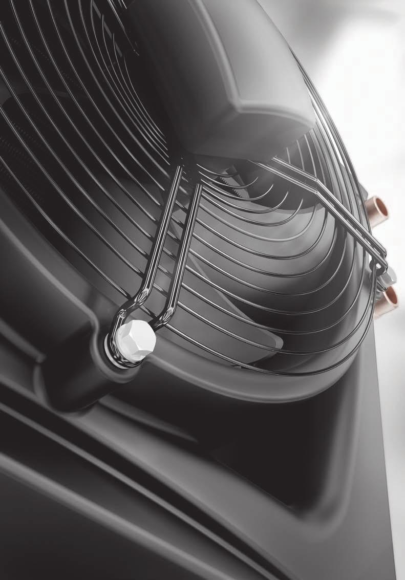
10 02 Water heaters V20 POWER 3-20 kw MAXIMUM AIR FLOW m 3 /h HORIZONTAL COVERAGE: 14 m VERTICAL COVERAGE: 8 m V25 POWER 5-25 kw MAXIMUM AIR FLOW m 3 /h HORIZONTAL COVERAGE: 22 m VERTICAL COVERAGE: 11 m V45 POWER kw MAXIMUM AIR FLOW m 3 /h HORIZONTAL COVERAGE: 22 m VERTICAL COVERAGE: 11 m ADVANTAGES: >> >> >> small weight: 9.8 kg unrivaled correlation of quality and price modern design WIDE RANGE OF APPLICATION: production halls sport facilities workshops 10

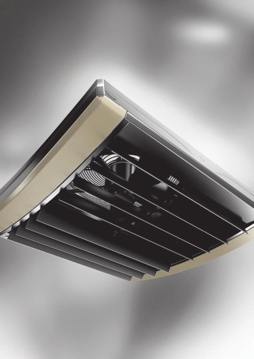
11 02 VR1 POWER kw MAXIMUM AIR FLOW m³/h HORIZONTAL COVERAGE: 25 m VERTICAL COVERAGE: 12 m VR2 POWER kw MAXIMUM AIR FLOW m³/h HORIZONTAL COVERAGE: 25 m VERTICAL COVERAGE: 12 m ADVANTAGES: >> >> >> attractive desing the biggest range of air stream in the market high output with low operation costs objects of worship supermarkets warehouses 11
12 02 Technical parameters 564 mm 585 mm 533 mm 313 mm 330 mm 318 mm 515 mm 640 mm 793 mm 570 mm 715 mm 785 mm Parameter Unit V20 V25 V45 VR1 VR2 number of rows in the heater maximum air consumption m³/h range of heating power kw weight of the device (without water) kg 9,8 17,5 19, size: height mm size: width mm size: depth mm maximum horizontal air coverage maximum vertical air coverage m m water volume dm³ 1,05 1,25 1,95 1,7 3,1 motor power kw 0,124 0,325 0,485 rated current A 0,54 1,43 2,2 maximum temperature of heating agent C maximum operating pressure MPa 1,6 power supply voltage V/ph/Hz ~230/1/50 diameter of connecting nozzles motor rotation revolutions " 3/4 obr/min Motor IP IP
13 02 VERTICAL COVERAGE V20 V25 / V45 VR1 / VR2 8 m 11 m 12 m HORIZONTAL COVERAGE 14 m 22 m 25 m VR1 / VR2 V25 / V45 V20 13
14 02 Technical parameters V20 Ventilator speed with ARW 0,6/1 regulator --- III II I ventilator power consumption m³/h output voltage of the regulator V noise level db(a) 52,3 41,6 28,8 variable power W horizontal coverage m vertical coverage m * reference conditions: room volume 1500m³, measurement taken at a distance of 5m V25 / V45 Ventilator speed with ARW 2,5 regulator --- V IV III II I ventilator power consumption V25 m³/h ventilator power consumption V45 m³/h output voltage of the regulator V noise level db(a) variable power W horizontal coverage m vertical coverage m * reference conditions: room volume 1500m³, measurement taken at a distance of 5m VR1 / VR2 Ventilator speed with ARW 2,5 regulator --- V IV III II I ventilator power consumption VR1 m³/h ventilator power consumption VR1 m³/h output voltage of the regulator V noise level db(a) variable power W horizontal coverage m vertical coverage m * reference conditions: room volume 1500m³, measurement taken at a distance of 5m 14
15 02 Technical parameters V20 Parameter T z /T p 50/30 70/50 80/60 90/70 T p1 Qp ,8 13 0,38 3,3 14,3 21 0,63 7,7 17,0 25 0,75 10,4 19,7 29 0,87 13, ,5 16 0,28 1,9 10,6 26 0,47 4,4 12,6 31 0,56 6,0 14,6 36 0,65 7, ,6 20 0,20 1,0 7,5 32 0,33 2,4 8,9 38 0,39 3,2 10,3 44 0,46 4, ,5 16 0,32 2,4 13,1 25 0,57 6,5 15,8 29 0,70 9,1 18,5 33 0,82 12, ,5 19 0,24 1,4 9,7 29 0,43 3,7 11,7 34 0,52 5,2 13,7 39 0,61 6, ,9 22 0,17 0,8 6,9 34 0,30 2,0 8,3 40 0,37 2,8 9,7 46 0,43 3, ,1 19 0,27 1,7 11,8 28 0,52 5,4 14,5 32 0,64 7,8 17,2 36 0,76 10, ,5 21 0,20 1,0 8,8 32 0,38 3,1 10,8 37 0,48 4,5 12,8 42 0,57 6, ,2 24 0,14 0,5 6,2 37 0,27 1,7 7,6 43 0,34 2,4 9,0 48 0,40 9, ,7 22 0,20 1,1 10,5 31 0,46 4,3 13,2 35 0,58 6,6 16,0 39 0,71 9, ,5 24 0,15 0,6 7,8 34 0,34 2,5 9,8 39 0,43 3,8 11,8 44 0,52 5, ,3 25 0,10 0,2 5,5 39 0,24 1,4 7,0 45 0,31 2,0 8,4 51 0,37 2, ,1 25 0,14 0,5 9,2 34 0,40 3,4 12,0 38 0,53 5,4 14,7 42 0,65 7, ,0 25 0,09 0,2 6,8 37 0,30 2,0 8,9 42 0,39 3,1 10,9 47 0,48 4, ,1 25 0,05 0,1 4,9 41 0,21 1,1 6,3 47 0,28 1,7 7,7 53 0,34 2,4 KEYWORDS: Tz Tp Tp1 Tp2 Pg Qp Qw - water temperature at the inlet to the device - water temperature at the outlet from the device - air temperature at the inlet to the device - air temperature at the outlet from the device - heating power of the device - air flow - water flow - pressure drop in the heat exchanger 15
16 02 V25 Parameter T z /T p 50/30 70/50 80/60 90/70 T p1 Qp ,8 6 0,43 1,2 18,0 10 0,79 3,4 21,8 13 0,96 4,7 25,6 15 1,13 6, ,3 6 0,36 0,9 15,3 12 0,67 2,5 18,5 14 0,82 3,5 21,8 17 0,96 4, ,6 8 0,24 0,4 10,8 15 0,47 1,3 13,1 18 0,57 1,9 15,3 21 0,68 2, ,8 8 0,17 0,2 8,6 17 0,38 0,9 10,5 21 0,46 1,2 12,3 24 0,54 1, ,1 10 0,14 0,2 6,5 20 0,28 0,5 7,9 24 0,35 0,7 9,2 28 0,41 1, ,9 10 0,34 0,8 16,2 15 0,71 2,8 20,1 17 0,88 4,0 23,8 19 1,05 5, ,5 10 0,28 0,6 13,7 16 0,60 2,1 17,0 18 0,75 3,0 20,2 21 0,89 4, ,7 10 0,16 0,2 9,7 19 0,42 1,1 12,0 22 0,53 1,6 14,2 25 0,63 2, ,2 11 0,14 0,2 7,7 21 0,34 0,7 9,6 24 0,42 1,1 11,4 28 0,50 1, ,7 13 0,12 0,1 5,8 23 0,25 0,4 7,2 28 0,32 0,6 8,5 32 0,38 0, ,6 13 0,24 0,4 14,4 19 0,63 2,2 18,2 21 0,80 3,4 22,0 23 0,97 4, ,7 13 0,16 0,2 12,2 20 0,53 1,7 15,5 22 0,68 2,5 18,6 25 0,82 3, ,0 14 0,13 0,2 8,6 22 0,38 0,9 10,9 26 0,48 1,3 13,1 29 0,58 1, ,6 15 0,12 0,1 6,8 24 0,30 0,6 8,7 28 0,38 0,9 10,5 32 0,46 1, ,2 17 0,10 0,1 5,1 26 0,22 0,4 6,5 31 0,29 0,5 7,9 35 0,35 0, ,1 17 0,13 0,2 12,5 23 0,55 1,8 16,4 25 0,72 2,8 20,2 27 0,89 3, ,9 17 0,12 0,1 10,6 24 0,47 1,3 13,9 26 0,61 2,1 17,1 29 0,76 2, ,4 18 0,10 0,1 7,5 26 0,33 0,7 9,8 29 0,43 1,1 12,0 33 0,53 1, ,1 19 0,09 0,1 5,9 27 0,26 0,5 7,8 31 0,34 0,7 9,6 35 0,43 1, ,7 21 0,08 0,1 4,4 29 0,19 0,3 5,9 34 0,26 0,4 7,2 39 0,32 0, ,2 21 0,10 0,1 10,7 27 0,47 1,3 14,6 29 0,64 2,3 18,3 31 0,81 3, ,1 22 0,09 0,1 9,1 28 0,40 1,0 12,4 30 0,54 1,7 15,6 33 0,69 2, ,7 23 0,08 0,1 6,4 29 0,28 0,5 8,7 33 0,38 0,9 11,0 36 0,48 1, ,5 23 0,07 0,1 5,0 31 0,22 0,3 7,0 35 0,31 0,6 8,8 39 0,39 0, ,3 24 0,06 0,1 3,7 32 0,16 0,2 5,2 37 0,23 0,4 6,6 42 0,29 0,5 KEYWORDS: Tz Tp Tp1 Tp2 Pg Qp Qw - water temperature at the inlet to the device - water temperature at the outlet from the device - air temperature at the inlet to the device - air temperature at the outlet from the device - heating power of the device - air flow - water flow - pressure drop in the heat exchanger 16
17 02 V45 Parameter T z /T p 50/30 70/50 80/60 90/70 T p1 Qp ,2 13 0,88 7,8 32,9 21 1,44 17,3 39,0 26 1,72 22,9 45,1 29 1,99 29, ,3 14 0,75 5,9 28,1 23 1,23 13,1 33,3 27 1,47 17,3 38,5 31 1,70 21, ,0 17 0,52 3,1 19,4 28 0,85 6,7 22,9 33 1,01 8,9 26,5 39 1,17 11, ,2 20 0,40 1,9 15,0 32 0,66 4,3 17,7 38 0,78 5,6 20,4 44 0,90 7, ,5 23 0,28 1,0 10,6 37 0,46 2,3 12,5 43 0,55 3,0 15,7 48 0,69 4, ,1 16 0,75 5,8 29,8 24 1,31 14,5 35,9 28 1,58 19,8 42,0 32 1,86 25, ,7 17 0,64 4,4 25,5 26 1,12 11,0 30,7 30 1,35 14,9 35,9 35 1,59 19, ,1 20 0,44 2,3 17,5 31 0,77 5,6 21,1 36 0,93 7,6 24,6 42 1,09 9, ,8 22 0,34 1,4 13,6 34 0,59 3,6 16,3 40 0,72 4,8 19,0 46 0,84 6, ,4 24 0,24 0,8 9,6 39 0,42 1,9 11,5 46 0,51 2,6 14,6 51 0,65 3, ,0 19 0,61 4,0 26,7 27 1,17 12,0 32,9 31 1,45 16,8 38,9 35 1,72 22, ,0 20 0,52 3,1 22,9 29 1,00 9,0 28,1 34 1,23 12,7 33,2 38 1,47 16, ,2 22 0,36 1,6 15,7 34 0,69 4,7 19,3 39 0,85 6,5 22,8 45 1,01 8, ,3 24 0,27 1,0 12,2 37 0,53 2,9 14,9 43 0,66 4,1 17,6 49 0,78 5, ,2 25 0,18 0,5 8,6 41 0,38 1,6 10,5 48 0,46 2,2 13,5 53 0,60 3, ,8 22 0,47 2,6 23,7 31 1,04 9,6 29,8 35 1,31 14,2 35,9 39 1,58 19, ,3 23 0,40 1,9 20,3 32 0,89 7,3 25,5 37 1,12 10,7 30,6 41 1,35 14, ,3 25 0,27 1,0 14,0 36 0,61 3,8 17,5 42 0,77 5,5 21,0 47 0,93 7, ,7 25 0,20 0,6 10,8 39 0,47 2,4 13,5 45 0,59 3,5 16,2 51 0,72 4, ,2 27 0,14 0,3 7,6 43 0,33 1,3 9,6 50 0,42 1,9 12,5 56 0,55 2, ,4 25 0,32 1,3 20,6 34 0,90 7,5 26,8 38 1,18 11,7 32,8 42 1,45 16, ,2 25 0,27 1,0 17,7 35 0,77 5,7 22,9 40 1,01 8,8 28,0 45 1,24 12, ,6 26 0,16 0,4 12,2 39 0,53 2,9 15,7 45 0,69 4,5 19,2 50 0,85 6, ,1 27 0,13 0,3 9,4 42 0,41 1,9 12,2 48 0,53 2,9 14,8 54 0,66 4, ,4 29 0,11 0,2 6,7 45 0,29 1,0 8,6 52 0,38 1,5 11,4 58 0,50 2,5 KEYWORDS: Tz Tp Tp1 Tp2 Pg Qp Qw - water temperature at the inlet to the device - water temperature at the outlet from the device - air temperature at the inlet to the device - air temperature at the outlet from the device - heating power of the device - air flow - water flow - pressure drop in the heat exchanger 17
18 02 VR1 Parameter T z /T p 50/30 70/50 80/60 90/70 T p1 Qp ,1 7 0,6 2,1 23,1 13 1,0 6,2 28,1 15 1,2 9,0 33,1 18 1,5 12, ,3 9 0,5 1,6 19,8 15 0,9 4,6 24,1 18 1,1 7,0 28,3 21 1,2 9, ,8 10 0,6 1,2 17,2 17 0,7 3,5 20,8 21 0,9 5,0 24,4 25 1,1 6, ,0 12 0,3 0,8 14,0 21 0,6 2,4 16,9 25 0,7 3,0 19,8 30 0,9 4, ,9 19 0,2 0,3 8,3 32 0,4 0,9 10,0 38 0,4 1,0 11,6 44 0,1 1, ,8 11 0,5 1,4 20,9 16 0,9 5,1 25,8 19 1,1 8,0 30,8 22 1,4 10, ,4 12 0,4 1,1 17,9 18 0,8 3,8 22,1 22 1,0 6,0 26,3 25 1,2 7, ,2 13 0,4 0,8 15,5 21 0,7 2,9 19,1 24 0,8 4,0 22,7 28 1,0 6, ,7 15 0,3 0,6 12,7 24 0,5 2,0 15,6 28 0,7 3,0 18,5 33 0,8 4, ,2 21 0,2 0,2 7,6 34 0,3 0,7 9,2 40 0,4 1,0 10,9 46 0,1 1, ,6 15 0,4 0,9 18,6 20 0,8 4,1 23,5 23 1,0 6,0 28,5 26 1,3 9, ,5 16 0,3 0,7 16,0 22 0,7 3,0 20,2 25 0,9 5,0 24,3 28 1,1 6, ,6 17 0,3 0,6 13,8 24 0,6 2,3 17,4 28 0,8 4,0 21,0 31 0,9 5, ,4 18 0,2 0,4 11,3 27 0,5 1,6 14,2 31 0,6 2,0 17,1 36 0,8 3, ,4 23 0,1 0,2 6,8 36 0,3 0,6 8,4 42 0,4 1,0 10,1 48 0,1 1, ,4 19 0,3 0,5 16,3 24 0,7 3,2 21,3 27 0,9 5,0 26,2 29 1,2 7, ,6 19 0,2 0,4 14,0 26 0,6 2,4 18,2 29 0,8 4,0 22,4 32 1,0 5, ,9 20 0,2 0,3 12,2 27 0,5 1,8 15,8 31 0,7 3,0 19,4 34 0,9 4, ,1 21 0,2 0,2 10,0 30 0,4 1,2 12,9 34 0,6 2,0 15,8 39 0,7 3, ,6 25 0,1 0,1 6,0 38 0,3 0,5 7,7 44 0,3 1,0 9,3 50 0,1 1, ,2 22 0,2 0,2 14,0 28 0,6 2,4 19,0 30 0,8 4,0 23,9 33 1,1 6, ,7 23 0,2 0,2 12,1 29 0,5 1,8 16,3 32 0,7 3,0 20,4 35 0,9 4, ,3 23 0,1 0,1 10,5 31 0,5 1,4 14,1 34 0,6 2,0 17,7 38 0,8 3, ,8 24 0,1 0,1 8,6 33 0,4 0,9 11,5 37 0,5 2,0 14,4 42 0,6 2, ,8 27 0,1 0,0 5,2 40 0,2 0,4 6,9 46,1 0,3 1,0 8,5 52 0,1 0,9 KEYWORDS: Tz Tp Tp1 Tp2 Pg Qp Qw - water temperature at the inlet to the device - water temperature at the outlet from the device - air temperature at the inlet to the device - air temperature at the outlet from the device - heating power of the device - air flow - water flow - pressure drop in the heat exchanger 18
19 02 VR2 Parameter T z /T p 50/30 70/50 80/60 90/70 T p1 Qp ,9 14 1,0 4,9 40,8 24 1,8 13,0 49,1 28 2,2 18,0 60,5 33 2,5 24, ,4 16 0,8 3,3 33,0 27 1,4 8,8 39,6 32 1,7 12,0 46,2 37 2,0 16, ,3 18 0,7 2,4 27,5 29 1,2 6,3 33,0 35 1,5 9,0 38,4 41 1,7 11, ,3 21 0,5 1,4 20,5 24 0,9 3,6 24,4 41 1,1 5,0 28,4 47 1,3 6, ,4 28 0,3 0,4 10,2 45 0,4 1,0 12,1 53 0,5 1,0 14,0 62 0,6 1, ,1 17 0,9 3,5 36,9 26 1,6 10,9 45,2 31 2,0 16,0 53,5 36 2,4 21, ,3 18 0,7 2,4 29,9 29 1,3 7,3 36,5 35 1,6 11,0 43,1 40 1,9 14, ,7 20 0,6 0,7 25,0 32 1,1 5,3 30,5 38 1,3 8,0 35,9 43 1,6 10, ,5 22 0,5 1,1 18,6 36 0,8 3,0 22,6 43 1,0 4,0 26,5 49 1,2 5, ,4 29 0,2 0,3 9,3 46 0,4 0,9 11,2 54 0,5 1,0 13,1 63 0,6 1, ,2 19 0,7 2,4 33,1 29 1,4 8,8 41,4 34 1,8 13,0 49,6 39 2,2 18, ,3 21 0,6 1,6 26,8 32 1,2 6,0 33,4 37 1,5 9,0 40,0 42 1,8 12, ,2 22 0,5 1,2 22,4 34 1,0 4,3 27,9 40 1,2 7,0 33,3 46 1,5 9, ,6 24 0,4 0,7 16,7 38 0,7 2,5 20,7 45 0,9 4,0 24,6 51 1,1 5, ,5 30 0,2 0,2 8,4 47 0,4 0,7 10,3 55 0,5 1,0 12,2 64 0,5 1, ,4 22 0,5 1,4 29,2 32 1,3 7,0 37,5 37 1,7 11,0 45,7 42 2,0 16, ,2 23 0,4 1,0 23,7 34 1,0 4,8 30,3 40 1,3 8,0 36,9 45 1,6 10, ,6 24 0,4 0,7 19,9 36 0,9 3,4 25,3 42 1,1 5,0 30,7 48 1,4 7, ,7 26 0,3 0,5 14,8 40 0,6 2,0 18,8 46 0,8 3,0 22,8 53 1,0 4, ,6 31 0,2 0,1 7,5 48 0,3 0,6 10,4 61 0,1 1,0 11,3 65 0,5 1, ,5 25 0,4 0,7 25,3 35 1,1 5,4 33,6 39 1,5 9,0 41,8 44 1,8 13, ,1 26 0,3 0,5 20,6 37 0,9 3,7 27,2 42 1,2 6,0 33,8 47 1,5 9, ,0 27 0,3 0,4 17,3 39 0,7 2,7 22,8 44 1,0 4,0 28,2 50 1,2 6, ,7 28 0,2 0,2 12,9 42 0,6 1,6 16,9 48 0,7 3,0 20,9 55 0,9 3, ,6 31 0,1 0,1 6,6 49 0,3 0,5 8,5 57 0,4 1,0 10,4 66 0,5 1,0 KEYWORDS: Tz Tp Tp1 Tp2 Pg Qp Qw - water temperature at the inlet to the device - water temperature at the outlet from the device - air temperature at the inlet to the device - air temperature at the outlet from the device - heating power of the device - air flow - water flow - pressure drop in the heat exchanger 19
 kg 22 power supply voltage V/ph/Hz ~230/1/50 motor power kw 0,485 rated current A 2,2 motor rotation rpm obr/min.")

20 02 VR-D Destratificator VR-D MAXIMUM AIR FLOW m 3 /h COVERAGE HORIZONTAL - 28 m COVERAGE VERTICAL - 15 m PARAMETER Parameter --- VR-D maximum air consumption m 3 /h 6500 maximal horizontal air coverage m 28 maximum vertical air coverage m 15 weight of the device (without water) kg 22 power supply voltage V/ph/Hz ~230/1/50 motor power kw 0,485 rated current A 2,2 motor rotation rpm obr/min The method of selection of the premises: Installation height - not less than 3/4 counting the height of the object height from the floor. Example of specifying the minimum amount Destratifikátora assembly VR: Hmin. = ¾ x H The object of height H = 12m, the minimum mounting height Destratifikátora VR - D: Hmin. = ¾ x 12 m = 9 m Motor IP IP 54 KEYWORDS: H L W - height - length - width Hmin. H L x W 20
21
22
23 03 Controls


24 03 Controls REGULATORS Parameter Model --- ARW0,6/1 ARW2,5/2 ARW3,0/2 ARW3,2/2 ARWE2,5 (0-10V) ARWE3,0 (0-10V) VTS article No power supply voltage V/ph/Hz ~230/1/50 permissible output current A 0,6 2,5 3,0 3,2 2,5 3,0 method of regulation --- manual gearshift switch automatic, signal 0-10V number of regulation levels on / off switch --- yes no maximum ambient temperature C 35 IP proection IP 54 Joint operation with the equipment Model --- ARW0,6/1 ARW2,5/2 ARW3,0/2 ARW3,2/2 ARWE2.5 ARWE3.0 VTS article No V20 pcs V25 pcs V45 pcs VR1 pcs VR2 pcs VALVES AND ACTUATORS CONTROLS PACKAGE Parameter BASIC: Valves and actuators Speed controller ARW 3,0/ Termostat TR Model --- VA-VEH202TA VTS article No power supply voltage V/ph/Hz 230/1/50 CONTROLS PACKAGE power W 1 nozzles " 3/4 kvs m³/h 4,5 opening/closing time p. 180 / 180 IP proection IP 54 PRESTIGE: Valves and actuators Speed controller ARW 3,0/ Programmed thermostat EH


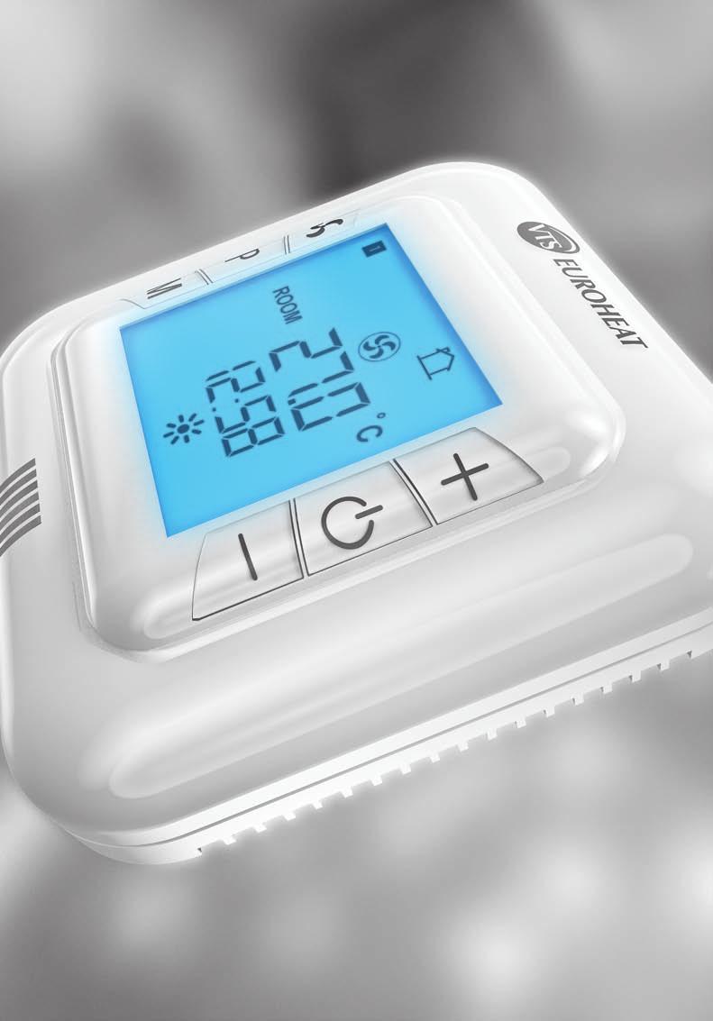
25 03 Controls CONTROLLERS Parameter Model --- Controler HMI VR (0-10V) PROGRAMMED Thermostat EH20.1 THERMOSTAT VTS article No power supply voltage V/ph/Hz ~230/1/50 2 x batteries 1.5 AA --- operating voltage V 230VAC/0-10VDC VAC load current A 1A dla 230VAC 0,02A dla 0-10V 3 setting range C 5 ~ 40 5 ~ ~ 30 modes of operation --- manual/automatic manual manual hour-week calendar --- yes no clock --- yes no measurement of temperature --- integrated to the device possibility to connect a separate temperature sensor pcs. 1 or 4 no output signal VDC on/off IP proectionip IP 30 Joint operation with the equipment Model Controler HMI VR (0-10V) PROGRAMMED Thermostat EH20.1 THERMOSTAT TR010 VTS article No ARW0,6/1; ARW2,5/2; ARW3,0/2; ARW3,2/2 no yes ARWE2,5; ARWE3,0 yes no Room sensor NTC --- to the HMI VR controler resistance measuring element kω NTC 10K installation --- surface maximum signal cable length m 100 ambient work parameters C 0 40 temperature measurement range C IP proection IP 20 25

26
27 04 KNOWLEDGE
28 04 KNOWLEDGE FAQ DEVICES 1. HOW SHOULD THE DIAMETERS OF THE MAIN SUPPLY PIPELINE BE SPACED IN CASE MORE HEATERS ARE CONNECTED? The diameter of the main pipe should be selected in such a way that the water flow rate does not exceed 2.5 m/s. This is caused by the need for a compromise between the investment costs associated with the size of the used tubes and operating costs, associated the water flow resistance in pipelines. We recommend the minimum diameters of the pipeline depending on the amount and type of heater devices connected to the bus line indicated in the following tables: Number heaters V45* Maximum flow Pipeline diameter [ ] 1 2,0 ¾ 2 4, ,0 1 ¼ 4 8,0 1 ¼ 5 10,0 1 ½ 6 11,9 1 ½ 7 13, , , ,9 2 *Heaters connected in series to one bus. Number heaters V20* Maximum flow Pipeline diameter [ ] Number heaters VR1* Maximum flow Pipeline diameter [ ] 1 0,9 ½ 2 1,8 ¾ 3 2,7 ¾ 4 3, , ,4 1 ¼ 7 6,3 1 ¼ 8 7,2 1 ¼ 9 8,1 1 ¼ 10 9,0 1 ½ *Heaters connected in series to one bus. 1 1,5 ¾ 2 3 ¾ 3 4, ¼ 5 7,5 1 ¼ ¼ 7 10,5 1 ¼ ¼ 9 13, *Heaters connected in series to one bus. Number heaters V25* Maximum flow Pipeline diameter [ ] Number heaters VR2* Maximum flow Pipeline diameter [ ] 1 1,1 ¾ 2 2,3 ¾ 3 3, , ,7 1 ¼ 6 6,8 1 ¼ 7 7,9 1 ¼ 8 9,0 1 ¼ 9 10,2 1 ½ 10 11,3 1 ½ *Heaters connected in series to one bus. 1 2,5 ¾ ,5 1 ¼ ½ 5 12,5 1 ½ , ,5 2 ½ ½ *Heaters connected in series to one bus. 28
29 04 KNOWLEDGE 2. HOW CAN I CONNECT THERMOSTAT TO THE VENTILATOR, SO THAT THE VENTILATOR SHUT DOWN TOGETHER WITH THE VALVE SHUTDOWN? The wiring diagrams contained in the technical documentation for unit heaters are included all possible configurations of electrical connections for the selected operating mode. If you are connecting only one heater, the thermostat can be connected in series with the phase wire behind the main switch / fuse installation. In this case, pay attention to the maximum thermostat contact load; load capacity should be at least 10 (3) A per one device. In the case of too little load on the thermostat connectors or more heaters are controlled by the thermostat, use electrical relay with the coil powered by the thermostat (230 V AC), working contact voltage will be 230 V AC, and working contact load will be adjusted to the amount of controlled devices. 3. CAN I CONNECT THE SUPPLY PIPE TO THE UPPER COLLECTOR OF WATER HEATER? Yes, you can, you should just remember to provide adequate space for mounting the valve actuator, which we recommend you to install on the return nozzle. Furthermore, a heat exchanger fed by the top collector will operate less efficiently due to the increased flow resistance of the heating medium. 4. CAN VR1 / VR2 / V20 / V25 / V45I HEATERS BE SUPPLIED WITH ANTI-FREEZE AGENT? 5. CAN VR1 / VR2 / MINI ALSO COOL THE AIR? Theoretically, the effect of device s work depends, inter alia, the medium flowing within the heat exchanger If the device is fed, for example, by a cold solution of water and glycol or ice-cold water, will start to work as the air cooler. Keep in mind, however, the phenomenon of condensation of water vapor on the heat exchanger as a result of lowering the temperature of the heat exchanger below the dew point of the air for given operating conditions. devices are not fitted with a drain, the user of the device needs to provide a drip tray or install a gutter under the device. Moreover, if you use theaters for cooling a phenomenon of dripping of the condensate water on the heat exchanger may occur. To prevent this, you should use the heater at a lower ventilator speed. The heaters are not suitable for cooling if they are installed under the roof. The condensed water dripping from the heat exchanger will drop to the floor. 6. CAN VR1 / VR2 / MINI HEATERS WORK TOGETHER WITH HEAT PUMPS? water heaters can work together with heat pumps. However, heat pumps provide a low parameter of the heating medium, so it is suggested to apply VR2 heater to such installations and V20/V45 due to the higher nominal power and double-breasted exchanger in relation to the single-channel heater VR1 / V25. Yes, you can, the most widely used antifreeze is a solution of water and glycol. However, please note that the fittings on the device may have limited resistance to glycol and make sure exactly what guidance on this topic are provided by the manufacturer of valves, circulating pumps, etc. The concentration of glycol can be up to 50%. 29
30 04 KNOWLEDGE FAQ Controls 1. WHAT ARE THE FUNCTIONS OF HMI VR CONTROL UNIT? The most important function of the control unit is the automatic operation in the heating mode. The controller also has a function of cooling (in summer it helps to air the room). Automatic signal from the controller HMI VR is used for selecting the ventilator speed, in cooperation with ARWE3.0. regulator. The signal is in the range 0-10V which is resulted by temperature difference between the measuring and the target temperature. 2. SHOULD I CONNECT THE ADDITIONAL EXTERNAL DETECTOR TO HMI VR CONTROL UNIT TO MEASURE THE TEMPERATURE? The controller has a built-in detector to measure the temperature of the NTC, so there is no need to connect an external sensor. If the driver is placed in another room, it is recommended that you connect it to an external NTC sensor specified in VTS EUROHEAT offer. When connected to a power supply controller automatically detects the sensor, it becomes the overriding element temperature measurement. 3. HOW CAN YOU TO ENTER THE MAIN DRIVER CONTROL PANEL OF HMI VR? To start the control panel the control unit must be actuated. In this case it is necessary to set the operating mode to OFF (off). In the control unit s mode OFF (OFF) simultaneously press M and + buttons and hold for 5 seconds. This will open the programming mode driver which is described in the table (next page). 4. CAN I PROGRAM THE CALENDAR (AND WHICH ONE) IN HMI VR CONTROL UNIT? The calendar is programmed in a five-day form, which means that the programmed first day (Monday) will be reproduced on consecutive working days (there is no possibility of individual settings for individual days). In the next programming step settings for Saturday and Sunday are entered separately. In both cases it is possible to program up to two heating periods a day. The programming is carried out in terms of hourly schedule with respect to the time in which the function of heating or cooling is supposed to be activated (cooling is a function suggested only in summer). By pressing the P you can switch the heating period to continuous mode (programmed heating periods will be deactivated but saved). Next pressing of P will return to the previous setting of the heating time for 7 days. 5. WHICH POWER SUPPLY IS REQUIRED BY HMI VR CONTROL UNIT? The control unit requires single-phase power: 1~230V +/-10%/50Hz. control unit programming table 1. Temperature sensor calibration calibration +/-8 C 3. Heating, cooling, heating/cooling selection 4. Maximum temperature 5~50 C 5. Minimum temperature 5~50 C 6. Selection of displayed temperature 7. Manual increasing of the value of the output signal (+ 0V - return to default settings) 9. Saving of settings after the power supply shutdown 10. Setting of a second temperature outside the programmed heating period (anti-freezing / economy) 11. The selection of operating for other temperature outside the heating period is set in p. 10 (anti-freezing / economy) ROOM (room) SET (set) 0, +1V, +2V, +3V, +4V 1: Yes 0: No 2~22 C 0 no operation and anti-freeze protection 1 anti-freeze protection, opening of the valve (2~22 C) 2 operating in the economy mode (2~22 C), opening of the valve and operation of the ventilator 12. Setting of clock minutes 0~ Seting of hours 0~ Selection of the weekday 1~7 15. RS485 address 1~ Software version 100E 30
31 04 KNOWLEDGE 6. HOW CAN I ENTER THE CALENDAR PROGRAMMING MODE? Hold P button for 3 seconds in the standard display menu in the ON mode (control unit switched on). 7. WITH HOW MANY DEVICES CAN HMI VR CONTROL UNIT COOPERATE? The control unit can operate with maximum eight rotary speed controllers. 8. DOES THE CONTROL UNIT HAVE AN OPPORTUNITY FOR MANUAL WORK ALONGSIDE WITH AUTOMATIC? Yes the control unit is equipped with M button; using it you can select the operating mode. When selecting the manual mode of operating we specify one of three levels: 30%,60% or 100% of signal. Another switch by pressing M button allows you to switch to automatic control. 9. DOES THE CONTROL UNIT HAVE A POSSIBILITY TO INCREASE OUTPUT SIGNAL DEPENDING ON ROOM VOLUME? Yes, the control unit enables the modulation and adding value to the output signal for different (larger) rooms. This function is useful when the automatic signal cannot achieve the target temperature. This applies mainly to buildings with an area exceeding 150m2. It is recommended to increase the existing 0-10V output signal respectively for the following objects: a) with the area of m²: +1V(+10%) b) with the area of m²: +2V(+20%) c) with the area of m²: +3V(+30%) d) with the area of 600 m² and more: +4V(+40%) e) the possibility to return to the standard settings + 0V 10. DOES THE CONTROL UNIT HAVE AN ANTI-FREEZE FUNCTION AND THE POSSIBILITY OF OPERATION IN ECONOMY MODE FOR ANOTHER TEMPERATURE? Yes. HMI control unit has the ability to select another temperature, which can be used to work in economy mode or as antifreeze protection of the heat exchanger. Both of these functions are available outside the programmed heating period. The selection of the additional temperature range of 2 ~ 22 C takes place in the main control unit settings in p. 10. In the next point of operation configuration, i.e. 11, the operation mode selection takes place. a) 0 means that functions antifreeze protection and work in economy mode are disabled. b) 1 will actuate antifreeze protection of the heater exchanger, open two-way valve when the room temperature drops below the set value in p. 10 (range 2~22 o C) c) 2 activates the work in economy mode outside the programmed heating period. This mode works the same way as a standard heating mode but for a different temperature (ventilator operation, flow opening) in the temperature range 2 ~ 22 o C. Both functions operate even when the controller is turned off or outside working hours set according in the calendar, provided the controller is connected to 230VAC power supply and operating mode 1 or 2 are selected in p. 11 of the main settings. 11. DOES THE CONTROL UNIT HAVE BMS FUNCTION? Yes, the control unit has the function of BMS on RS485 interface and communication by MODBUS RTU protocol. 31

32
1.1 VTS: number 1 in the world pillars of success
 Heating Unit 01 VTS GROUP 1.1 VTS: number 1 in the world 1.2 3 pillars of success 02 2.1 water hearers Modernity Innovativeness Energy efficiency 2.2 Assembly 2.3 VR-D destratifier 2.4 Automation 03 TECHNICAL
Air curtain.
 Air curtain www.wingbyvts.com 01 VTS GROUP 1.1 VTS: Manufacturer No. 1 in the world 1.2 3 constituents of success 02 2.1 air curtains 2.2 Silence and power 2.3 Design and performance 2.4 Quality and design
Carisma Fly Carisma Fly-ECM. Made in. Italy. High Wall Fan Coil. Air Conditioning ENVIRONMENTAL COMFORT
 Made in Italy Air Conditioning High Wall Fan Coil -ECM QUALITY MANAGEMENT SYSTEMS ISO 9001 - Cert. n 0545/5 www.eurovent-certification.com www.certiflash.com ENVIRONMENTAL COMFORT CONTENTS Introduction
0 C to 50 C ( 32 F to 122 F ) 0% to 95% R.H. non-condensing. 30 to 95% R.H. Dry contact across terminal BI1, BI2 & UI3 to Scom
 0% to 95% R.H. non-condensing. 30 to 95% R.H. Dry contact across terminal BI1, BI2 & UI3 to Scom") Viconics VT7350 Series PIR Ready Fan-coil Controllers General The VT7350 series are PIR Ready low-voltage microprocessor-based fan-coil controllers. Models are available controlling single speed and multi-speed
Viconics VT7350 Series PIR Ready Fan-coil Controllers General The VT7350 series are PIR Ready low-voltage microprocessor-based fan-coil controllers. Models are available controlling single speed and multi-speed
Technical documentation
 Technical documentation AIR WATER HEATERS IN STEEL CASING S SERIES MODELS: REVENTON GROUP S1-3S REVENTON GROUP S2-3S REVENTON GROUP S3-3S REVENTON GROUP S4-3S ENG TECHNICAL DOCUMENTATION Table of contents
DUCTLESS VENTILATION WITH HEAT RECOVERY. OXeN ductless ventilation unit
 DUCTLESS VENTILATION WITH HEAT RECOVERY OXeN ductless ventilation unit OXeN DUCTLESS VENTILATION UNIT Simple ventilation solution OXeN ventilation unit is: the easiest way to create mechanical ventilation
High wall fan coils Climmy FHW/FHW-ECM. Technical Catalogue
 High wall fan coils Climmy FHW/FHW-ECM Technical Catalogue Versions and Main components MODELS WITHOUT ELECTRIC HEATER All versions are available without valves, with 2 way valve or with 3 way valve fitted
American.
 American 2018 www.vtsgroup.com 01 VTS Group 02 Designer support 1.1 VTS Group... 05 1.2 The 3 Elements of Success... 08 2.1 ClimaCAD Online 4.0 (CCOL 4)... 12 2.2 VTS BIM... 14 03 Units 04 Technical Parameters
N M AirControl AHU. Control manual
 N 10.63 M 03-2016 AirControl AHU Control manual EN CONTENTS PAGE 1 - MONITORING AND CONTROL 2 1.1 The program 2 1.2 The HMI terminal 2 1.3 The controller 4 1.4 Description of the air handling units 4
OXeN. Ductless ventilation with heat recovery.
 OXeN Ductless ventilation with heat recovery www.flowair.com We are an expert in providing complete heating and ventilation solutions for medium and big cubature buildings. Our offer consists of three
Product is subject to and complies with Regulation (UE) N.327/2011. cert. n Fan Coil Unit Cassette SkyStar Jumbo ECM. technical catalogue
 N.327/2011. cert. n Fan Coil Unit Cassette SkyStar Jumbo ECM. technical catalogue") cert. n. 0545 Product is subject to and complies with Regulation (UE) N.327/2011 Fan Coil Unit Cassette SkyStar Jumbo ECM technical catalogue SkyStar Jumbo ECM Table of contents SkyStar Jumbo ECM TABLE
cert. n. 0545 Product is subject to and complies with Regulation (UE) N.327/2011 Fan Coil Unit Cassette SkyStar Jumbo ECM technical catalogue SkyStar Jumbo ECM Table of contents SkyStar Jumbo ECM TABLE
Series. Suspended air supply units with the air capacity up to 4100 m 3 /h in the sound- and heat-insulated casing with the water heater
 SUPPLY UNITS Series VENTS PA E Series VENTS PA W A13 control panel A13 control panel Suspended air supply units with the air capacity up to 3350 m 3 /h in the sound- and heat-insulated casing with the
ST 53.1 User s manual
 Tech - 1 - ST 53.1 User s manual Table of contents I. Safety... 3 II. Description... 4 III. Installation... 4 IV. Operating the Controller... 6 IV.a) Principle of Operation... 6 IV.b) Control... 6 V. Controller
No. 1 in Europe New on offer air curtain GUARD
 No. 1 in Europe New on offer air curtain H E A T E R S A I R C U R T A I N S No. 1 in Europe SONNIGER IS AN EUROPEAN PRODUCER OF MODERN, ECOLOGICAL/ECO-FRIENDLY AND OPTIMALLY SELECTED UNITS FOR INDUSTRIAL
HEATING AND COOLING DEVICE AGC
 GDYNIA HEATING AND COOLING DEVICE - AGC 2013 1/8 HEATING AND COOLING DEVICE AGC SERVICE phone.: (+48 58) 783 99 50/51 Fax: (+48 58) 783 98 88 mobile: (+48) 510 098 081 E-mail: serwis@klimor.pl GDYNIA,
OEM Alpha Thermostat direct Analog
 OEM Alpha Thermostat direct Analog The OEM Alpha Thermostat direct Analog is a high-quality room thermostat in modern design for the registration and regulation of the desired room temperature, offering
Fire Extinguishing Control Panel INSTRUCTION MANUAL. Revision 8/ Instruction Manual Page 1 Revision 8/01.17 of 63
 Fire Extinguishing Control Panel FS5200Е INSTRUCTION MANUAL Revision 8/01.17 Instruction Manual Page 1 1. 2. 3. 4. 4.1. 4.2. 4.2.1. 4.2.2. 4.2.3. 4.2.4. 4.2.5. 4.2.6. 4.2.7. 4.2.8. 4.2.9. 4.2.10. 4.2.11.
Epsilon Echos kw. General information Air-Water unit with scroll compressors driven by DC inverter. Unique selling points
 Epsilon Echos+ 5 38 kw General information Air-Water unit with scroll compressors driven by DC inverter Configuration /LN: Low noise unit /HP: Reversible heat pump /LE /HP: Reversible condensing unit Unique
XLH210: controller for gas leak detectors
 pag. 1 / 7 XLH210: controller for gas leak detectors Dixell introduces the new digital controllers designed to be combined with 4 20mA gas leak detectors. XLH210 is a microprocessor based controller, designed
Easy-Stat. Wireless Programmable Room Thermostat Pt No
 Easy-Stat Wireless Programmable Room Thermostat Pt No 7.2000050 1 Installing the receiver The receiver must be installed into the boiler control panel, refer to the boiler installation manual for guidance.
NEW. Wall Controls. Air Conditioning Ceiling Air Conditioning Elegant. Cert. n 0545
 NEW Wall Controls Cert. n 0545 Air Conditioning Ceiling Air Conditioning Elegant CONTENTS Page Introduction 3 Main components 4 Dimension, Weight, Water content 5 Main technical figures 6 Working conditions
Gas Detection System TOX ALARM DG2000-Garage
 Gas Detection System TOX ALARM DG2000-Garage Gas Detection System 32 independent programmable channels 2 programmable alarm levels for each gas = up to 6 for each channel LCD alphanumeric display of gas
Technical documentation DTR AIR WATER HEATERS IN EPP CASING HC-3S SERIES
 Technical documentation DTR AIR WATER HEATERS IN EPP CASING HC-S SERIES PL TECHNICAL DOCUMENTATION Table of contents Heating coil: made of aluminum and copper. The temperature of the heating factor is
ErP OPERATIONS MANUAL FOR AIR HEATER PROTON ECO. PROTON ECO Three-speed AC-motor
 05010416 OPERATIOS MAUAL FOR AIR HEATER PROTO ECO ErP 2015 PROTO ECO Three-speed Safety precautions Construction and dimensions Technical parameters Installation E RU www.protongroup.org COTETS Operations
User manual CLIMATIC 200/400 - Controller. Providing indoor climate comfort
 User manual CLIMATIC 2/4 - Controller Providing indoor climate comfort MUL35E-56 9-26 INDEX CONTENTS PAGE INDEX 1 GENERAL DESCRIPTION 2 THE KEYPAD, Climatic 2 3 THE KEYPAD, Climatic 4 4 THE KEYPAD REMOTE
Weekly thermostat for boilers Galan - regulator for management of heating elements and circuit SolarSentinel-DBTW Users guide.
 Weekly thermostat for boilers Galan - regulator for management of heating elements and circuit SolarSentinel-DBTW Users guide. SHORT DESCRIPTION: 1. Device is applicable to: - Burners; - Electric boiler;
OXeN. Ductless ventilation with heat recovery.
 OXeN Ductless ventilation with heat recovery www.flowair.com FLOWAIR System COMPLETE HEATING AND VENTILATION SOLUTIONS FLOWAIR has a complete heating and ventilation system for industrial and public buildings.
LZT High efficiency air to water heat pumps with E.V.I. compressors
 High efficiency air to water heat pumps with E.V.I. compressors -20 C +43 C +65 C E.V.I. C.O.P. 4,1 The series of high efficiency heat pumps has been specifically designed for use with radiant floor heating
BLAUAIR AUTOMATIC CONTROL SYSTEM
 BLAUAIR AUTOMATIC CONTROL SYSTEM S30 (KVENT, TH-TUNE) S31 (KVENT) S32 (KVENT, PGDE) EN USER S MANUAL CONTENTS Safety requirements... 3 Purpose... 4 Technical data... 5 Installation and set-up... 6 Control...
Blue Box Epsilon Echos +
 Blue Box Epsilon Echos + 5 38 kw General information Air-Water unit with scroll compressors driven by DC inverter Packaged version in 5 sizes Nominal cooling capacity (A35;W7): 6 26 kw Nominal heating
1. Product description
 1. Product description Technical data sheet clima DL-110 Available inputs and outputs The clima DL-110 is a universal room controller. It is suitable for controlling static heating/cooling systems (like
Technical documentation DTR
 Technical documentation DTR ENG TECHNICAL DOCUMENTATION Table of contents. INTRODUCTION. PRECAUTIONS. TRANSPORT. PACKAGE CONTENT. USE AND PRINCIPLE OF OPERATION. DEVICE CONSTRUCTION, DIMENSIONS, TECHNICAL
Installer Manual KNX Touchscreen Thermostat
 Installer Manual 02952 KNX Touchscreen Thermostat Index GENERAL FEATURES AND FUNCTIONALITY from page 5 ETS PARAMETERS AND COMMUNICATION OBJECTS from page 7 COMMUNICATION OBJECTS GENERAL FEATURES AND FUNCTIONALITY
GMA 301. Operation Manual. Worldwide Supplier of Safety Solutions. Part Number
 Worldwide Supplier of Safety Solutions GfG Instrumentation 1194 Oak Valley Drive #20 Phone: 734-769-0573 Fax: 734-769-1888 E-Mail: info@gfg-inc.com Internet: www.gfg-inc.com GMA 301 Operation Manual Part
Ocean Breeze Model QU700 Programmable Digital Touchscreen Climate Control
 Ocean Breeze Model QU700 Programmable Digital Touchscreen Climate Control Ocean Breeze 2951 SE Dominica Terrace, Stuart, Florida 34997 Tel: 772 2200038 obr@oceanbreezeac.com http://www.oceanbreezeac.com
TERM-E ELECTRIC HEATING AND VENTILATION UNITS
 ELECTRIC HEATING AND VENTILATION UNITS INTENDED USE The heating units with axial fans, metal casing and electric heaters are designed to heat rooms such as: industrial halls, workshops, warehouses, commercial
DEVIreg Opti Electronic Timer Thermostat fulfilling Eco Design Directive
 DEVIreg Opti Electronic Timer Thermostat fulfilling Eco Design Directive www.devi.com Table of Contents 1. Introduction..................................... 2 2. Technical Specifications.........................
Control solutions Biofloor
 TEF234 Electronic room thermostat with display 230V & 24V COMAP proposes a new control system for heating and cooling underfloor. Consisting of a 6 or 10- channels controller (MCF234), analogic (TAF234)
CZT CZT. High efficiency air to water heat pumps with E.V.I. compressors E.V.I. HP OTHER VERSIONS ACCESSORIES
 High efficiency air to water heat pumps with E.V.I. compressors infolinia: +48 691 262 691-15 C +63 C +43 C E.V.I. HP The series of high efficiency heat pumps has been specifically designed for use with
TopVent Design Handbook
 TopVent Design Handbook Recirculation Units and Supply Air Units for Heating and Cooling High Spaces TopVent Content TopVent DHV Recirculation unit for heating high spaces TopVent NHV Recirculation unit
SERVICE INSTRUCTION R410A. WALL MOUNTEDtype SPLIT TYPE ROOM AIR CONDITIONER INVERTER. Models Indoor unit Outdoor unit AO* R09LECN AO* R12LECN
 SERVICE INSTRUCTION SPLIT TYPE ROOM AIR CONDITIONER WALL MOUNTEDtype INVERTER Models Indoor unit Outdoor unit AS* A09LEC AS* A12LEC AO* R09LECN AO* R12LECN R410A CONTENTS 1. DESCRIPTION OF EACH CONTROL
Ocean Breeze Model QU700 Programmable Digital Touchscreen Climate Control
 Ocean Breeze Model QU700 Programmable Digital Touchscreen Climate Control Ocean Breeze 2951 SE Dominica Terrace, Stuart, Florida 34997 Tel: 772 2200038 obr@oceanbreezeac.com http://www.oceanbreezeac.com
Installation, Service, and Troubleshooting Instructions
 33CS TEMP System Unitary Controller Thermostat Installation, Service, and Troubleshooting Instructions Page GENERAL........................................ 2 TEMP System Components......................
AirTrak. Digital Control System. User Manual. Touchscreen Systems
 AirTrak Digital Control System User Manual Touchscreen Systems Rev. 10-29-15 1 2 Table of Contents OVERVIEW... 8 NETWORKING... 9 AIRTRAK DEFAULT SETTINGS... 9 Unit Operating Modes... 10 MRT Controls...
GreenCon On/Off Room Thermostat
 Description Features: Scandinavian design with white backlight; User-friendly interactive interface; Room temperature display and settings; 12 or 24 hour clock display and settings; Three-speed manual/automatic
SD2. Differential Controller. Operating and Installation Instructions F2 72.3
 SD2 Differential Controller Operating and Installation Instructions F2 72.3 i Please follow the safety information and read these Instructions carefully before putting the system into operation. Safety
ARATON 2100 TX 1 AURATON 2100 TX. Advanced Remote Control Programmable Thermostat
 ARATON 2100 TX 1 AURATON 2100 TX Advanced Remote Control Programmable Thermostat 2 ARATON 2100 TX I. INTRODUCTION This thermostat can replace most common residential thermostat and is designed to be used
REPEATER FS5200R INSTRUCTION MANUAL
 REPEATER FS5200R INSTRUCTION MANUAL Instruction Manual Page1 CONTENTS 1. Introduction... 3 2. Function... 3 3. Technical data... 3 4. Contents of delivery... 4 5. General information... 5 6. Duty Mode...
Control Panel Checklist
 Control Panel Checklist Versatronik -C Panel Checklist Option Selection for Control Panel Quotes Checklist Control Panel Checklist Section 1 General Information Customer name Phone number Fax number Email
POCKET GUIDE 2011 ELECTRICAL BOARDS FOR REFRIGERATING INSTALLATIONS
 POCKET GUIDE 2011 ELECTRICAL BOARDS FOR REFRIGERATING INSTALLATIONS products index 2 expert nano 06 plus200 EXPERT DATALOGGER 24 ecp_ base4 u vd 40 PEV pulse 60 expert nano 200 NANO 1CF 08 Plus300 EXPERT
REMOTE CONTROL FOR CHILLER MYCHILLER
 REMOTE CONTROL FOR CHILLER MYCHILLER GENERAL FEATURES... 3 MAIN FUNCTIONS AND EQUIPMENT:... 3 LCD DISPLAY... 4 KEYBOARD... 5 BOARD CONFIGURATION... 7 LIST OF MAIN PARAMETERS... 7 CONFIGURATION OF MAIN
OJ Waterline control system
 OJ Waterline control system THERMOSTATS FOR COMFORT HEATING AND SNOW MELTING Product presentation Mk3 It s all about Room Temperature Control! The essential main goals are: Comfort Flexibility Reliability
Carisma Fly. Made in. Italy. Wall-mounted Fan Coil. Air Conditioning ENVIRONMENTAL COMFORT.
 Made in Italy Air Conditioning Wall-mounted Fan Coil QUALITY MANAGEMENT SYSTEMS ISO 9001 - Cert. n 0545/5 www.eurovent-certification.com www.certiflash.com ENVIRONMENTAL COMFORT CONTENTS Introduction Version
LZA High efficiency air to water heat pumps with HP compressor
 High efficiency air to water heat pumps with HP compressor -10 C +43 C +60 C HP C.O.P. 4,1 The series of high efficiency heat pumps has been specifically designed for use with radiant floor heating systems
Replaceable LED modules. Sleep or unattended mode. Auto-silence and auto-acknowledge
 Replaceable LED modules 11 Alarm Sequences as per ISA-18.1 standard Each channel/window fully field programmable RS232 or RS485 MODBUS-RTU communication Repeat relay for each window and multifunction relays
Semi flush-mount room thermostat with KNX communications For VAV heating and cooling systems
 s 3 72 Semi flush-mount room thermostat with KNX communications For VAV heating and cooling systems RDU34 KNX bus communications (S-mode and LTE mode) Backlit display PI / P control Outputs for DC 0 0
Honeywell Homes T3, T3M & T3R
 Honeywell Homes T3, T3M & T3R PRODUCT SPECIFICATION SHEET Honeywell T3 & T3M Programmable Thermostat Honeywell T3R Programmable Thermostat The T3, T3M & T3R thermostats are designed to provide automatic
M2500 Engine Controller Installation Manual
 M2500 Engine Controller Installation Manual Revision: 23-04-2012 Page 1 Contents 1 Preface... 4 2 Installation... 5 3 Terminal Connections... 6 4 Inputs... 7 4.1 Power Supply... 7 4.2 Mode/ Control Inputs...
intelligent controls for hydronic floor heating
 intelligent controls for hydronic floor heating FLOOR HEATING HYDRONIC FLOOR HEATING ELECTRIC HVAC CONTROLS & POWER THERMOSTATS FOR HYDRONIC FLOOR HEATING PRODUCT CATALOGUE 2016 MASTER PROGRAMME, SUPPLY
VERSO DOMEKT. Residential ventilation units m³/h. Non residential ventilation units m³/h
 VENTILATION equipment VENTILATION equipment content DOMEKT Residential ventilation units 50 1 000 m³/h 15 VERSO Non residential ventilation units 1000 34 000 m³/h 61 Domekt R 17 Domekt R 200 V 19 Domekt
1.7. Insulation fault evaluators EDS460/490 EDS461/491
 Dipl.-Ing. W. Bender GmbH & Co. KG Londorfer Str. 65 35305 Grünberg Tel.: 06401 807-0 Fax: 06401 807-59 Insulation fault evaluators EDS460/490 EDS461/491 Insulation fault evaluators with display and control
LYRIC T4, T4R& T4M PRODUCT SPECIFICATION SHEET FEATURES
 LYRIC T4, T4R& T4M PRODUCT SPECIFICATION SHEET Honeywell T4 & T4M Programmable Thermostat Honeywell T4R Programmable Thermostat The T4, T4M and T4R thermostats are designed to provide automatic time and
DAP III Zone Master User s Guide
 DAP III Zone Master User s Guide Data Aire, Inc. 230 West BlueRidge Avenue Orange, California 92865 Document Number 600-000-788 March 2010 Revision 1.0 Document # 600-000-788 1 Overview The Data Aire DAP
Series VENTS MPA...W. Supply units with the air capacity up to 6500 m 3 /h in the compact sound- and heat-insulated casing with water heater
 SUPPLY UNITS Series Series LCD control panel SAS908 control panel Supply units with the air capacity up to 3500 m 3 /h in the compact sound- and heat-insulated casing with electric heater Supply units
Multi-Zone Wireless Control Training Systems ( )
") Multi-Zone Wireless Control Training Systems 593306 (3467-00) LabVolt Series Datasheet Festo Didactic en 120 V - 60 Hz 11/2018 Table of Contents General Description 2 Courseware 2 Topic Coverage 3 List
Multi-Zone Wireless Control Training Systems 593306 (3467-00) LabVolt Series Datasheet Festo Didactic en 120 V - 60 Hz 11/2018 Table of Contents General Description 2 Courseware 2 Topic Coverage 3 List
K-Controller Brochure.qxp_ Controller Brochure 2/27/17 3:03 PM Page 4 Versa IC Platform
 Versa IC Platform VERSA IC Integrated Control Platform Raypak s VERSA IC combines modulating temperature control, safety limits, and ignition programming into one user- friendly Integrated Control Platform.
Perfect match for Carrier fan coil units Carrier Thermostats & Valves
 Perfect match for Carrier fan coil units Carrier Thermostats & Valves Carrier Thermostats & Valves The state-of-the-art Carrier TMS LCD Room Thermostats and VLV Motorized Valves are designed to perfectly
WLM3 the 3 rd generation of the OJ Waterline TM Control Systems. Industry leading intelligence, control SLIDE OJ Electronics
 WLM3 the 3 rd generation of the OJ Waterline TM Control Systems Industry leading intelligence, control and operation SLIDE 1 Designed to deliver value for all. Benefits; Reliability - Fit and Forget Flexibility
LSA LSA A + Air cooled water chillers with axial fans VERSIONS ACCESSORIES
 LS ir cooled water chillers with axial fans + LS The LS water chiller range has been designed for small and medium residential and commercial applications. They are suitable for generating chilled water
1.7 A-ISOMETER IRDH575. RoHS. Dipl.-Ing. W. Bender GmbH & Co. KG Londorfer Str Grünberg Tel.: Fax:
 Dipl.-Ing. W. Bender GmbH & Co. KG Londorfer Str. 65 505 Grünberg Tel.: 060 807-0 Fax: 060 807-59 A-ISOMETER IRDH575 Insulation monitoring device for unearthed AC, DC and AC/DC systems (IT systems) with
CLEVER CONTROL Version: V3
 CLEVER CONTROL Version: V3 INSTALLATION AND FUNCTIONING MANUAL USER AND BASIC VERSION Please, read these instructions carefully before attempting installation SECURITY ADVISE SIMBOLS Attention, Danger,
SLS 1202 to With or without total heat recovery. u Air Cooled Screw Chillers. 262 to 916 kw. Engineering Data Manual
 u Air Cooled Screw Chillers SLS 1202 to 4004 With or without total heat recovery 262 to 916 kw Engineering Data Manual EDM SLS407-A.4GB Date : December 2008 Supersedes : TM SLS407-A.3GB/11.06 Specifications
Energy-efficient heat source provides comfort in large rooms
 AIR HEATER NOZ NOZ air heater Energy-efficient heat source provides comfort in large rooms When it comes to providing large, and often high buildings, with the best possible source of efficient heating
ErP OPERATIONS MANUAL FOR AIR HEATER PROTON AST. PROTON AST Air Heater with the anemostat
 05010416 OPERATIOS MAUAL FOR AIR HEATER PROTO AST ErP 2015 PROTO AST Air Heater with the anemostat Safety precautions Construction and dimensions Technical parameters Installation E RU www.protongroup.org
SPECIFICATION GUIDE FLEXAIR. Possibility to add auxiliary heaters: Gas, Electrical Heater, Hot Water Coil Possibility to add Heat Recovery Module
 SPECIFICATION GUIDE FLEXAIR Air-cooled packaged Rooftop unit Cooling only or Heat Pump Nominal cooling capacity: 85 to 234 kw Nominal heating capacity: 83 to 226 kw Possibility to add auxiliary heaters:
REA22 Room Temperature Controller
 REA22 Room Temperature Controller Basic Documentation Issue: 2.0 Controller series: A CE1P2276E 31.03.1999 Siemens Building Technologies Landis & Staefa Division Siemens Building Technologies Ltd. Landis
CWX 6 - CWX 8 - CWX 10 CASSETTE TYPE TERMINAL UNIT
 TECHNICAL INSTRUCTIONS CWX 6 - CWX 8 - CWX 10 CASSETTE TYPE TERMINAL UNIT Cooling Heating CWX 6 2 pipes 6.00 kw 7.70 kw CWX 8 2 pipes 8.00 kw 10.50 kw CWX 10 2 pipes 9.92 kw 13.00 kw November 2008 10 12
Touch Screen Thermostat. MTSC/SUPER, MTSC24/SUPER Series. MTS/SUPER, MTS24/SUPER Series. Owner s manual and technician settings
 Touch Screen Thermostat MTSC/SUPER, MTSC24/SUPER Series MTS/SUPER, MTS24/SUPER Series Owner s manual and technician settings -2 - Index 1. Owner s Manual... 4 1.1 Quick Guide. 4 1.2 Turning the unit ON
Dunham Bush Air Cooled Screw Chiller AFVX B 6SR Series
 Dunham Bush Air Cooled Screw Chiller AFVX B 6SR Series Type of Compressors Compressor Rotary Scroll Reciprocating Screw Centrifugal Air Cooled Chiller 77 ~ 329TR (270 ~ 1156 kw) ACDX Series 100 ~ 520TR
ECL Comfort 300 / V a.c. and 24 V a.c.
 Data sheet ECL Comfort 300 / 301 230 V a.c. and 24 V a.c. Application The ECL Comfort 300 / 301 is an electronic temperature controller which can be loaded with selected applications by means of an ECL
42AM. Air heaters PRODUCT SELECTION DATA
 PRODUCT SELECTION DATA The best solution for heating large spaces Ensures buildings warm up ultra-fast Excellent diffusion via patented JET+ double deflection technology Air heaters 4AM Translation of
T8000 Series T8600 MODBUS Touch Screen Thermostat
 T8 Series T86 MODUS Touch Screen Thermostat T86 MODUS Series Touch Screen Thermostat Application T86 JS/R Touch screen thermostats are designed to control heating, cooling, or air conditioning unit in
NKW. Heater series HEATERS
 HEATERS Heater series Applications Duct electrical heaters are designed for heating of supply air in rectangular ventilating system and are applicable in supply or supply and exhaust units. Design The
LMV52 Control. Specifications. Document No. LV February 3, Product Description. Sample Specification
 LMV52 Control Product Description February 3, 2017 The LMV52 is a microprocessor-based burner management system with matching system components for the control and supervision of forced draft burners.
ETNC24-FC-BAC-PIR-01 Owner s manual & Technician Settings
 ETNC-FC-BAC-PIR- Rev. Index Operating instructions....- Turning the thermostat and OFF Selecting temperature scale Adjusting the Set point temperature (for set point and set points configurations) Selecting
RCS Residential Control Systems Inc.
 RCS Residential Control Systems Inc. Model TZ16 Z-Wave Communicating Thermostat with Rev P HVAC Control Unit INSTALLATION AND OPERATION MANUAL DCN: 141-00882 Rev 02 5/18/06 This manual applies to the following
FPC-02 Series. Installation and Operating manual
 Installation and Operating manual Index Introduction.... 3 FPC-02 Installation notes......... 4 Wiring the FPC-02-120V, FPC-02-120V-MDB. 5 Wiring the FPC-02-240V, FPC-02-240V-MDB. 6 Operating instructions.
Modular Standard HP Chiller 1/4 screw compressor with Carel driver
 Program for pco¹ pco 2 and pcoc Modular Standard HP Chiller 1/4 screw compressor with Carel driver Manual version 1.0 25 September 2003 Program code: FLSTDmMSDE Do we want you to save you time and money?
Project Name: Location: Engineer: Contractor: I. GENERAL
 Part I - General Part II - Product Part III - Installation Project Name: Location: Engineer: Contractor: I. GENERAL I. PRODUCT Rep: Date: A. Supply and install modulating and condensing boiler(s) as specified
Insulation fault evaluator EDS460-DG
 Insulation fault evaluator for localising insulation faults in DC IT systems with a number of branch circuits where high system leakage capacitances are involved Preliminary data sheet TDB108021en/09.2008
Trinity Tft High Efficiency Gas Condensing Boiler & Water Heater
 Part I - General Part II - Product Part III - Installation Project Name: Location: Engineer: Contractor: I. GENERAL Rep: A. Supply and install modulating and condensing boiler(s) as specified herein. Date:
GreenCon On/Off Room Thermostat
 Description Features: Scandinavian design with white backlight; User-friendly interactive interface; Room temperature display and settings; 12 or 24 hour clock display and settings; Three-speed manual/automatic
SCAN200E USER S MANUAL
 SCAN200E USER S MANUAL Code No. 2071 1052 rev. 1.4 Code No. 2071 1052 Rev. 1.4 Page 2/16 SCAN200E User s Manual Foreword This manual is for SCAN200E Controller running software version 2.03 or later. We
ErP OPERATIONS MANUAL FOR AIR HEATER PROTON JET. PROTON JET Air Heater with with AirJet nozzle.
 OPERATIOS MAUAL FOR AIR HEATER PROTO JET ErP 2015 05010516 PROTO JET Air Heater with with AirJet nozzle Safety precautions Construction and dimensions Technical parameters Installation E RU www.protongroup.org
Installation & User s Instructions
 Installation & User s Instructions 8 080 shown Part No. 00 day Wired Digital Programmer & Room Sensor Part No. 080 day Wireless Digital Programmer & Room Sensor Part No. 00 hr Wireless Digital Programmer
Hydronic & HVAC Control Systems
 tekmar 218 Full Line Catalog Hydronic & HVAC Control Systems HVAC Multi-Staging Alternative Energy Zoning Snow Melting Setpoint tekmarcontrols.com tekmarcontrols.com Better Design, Better Control, Better
PRELIMINARY EDITION
 3 131 PRELIMINARY EDITION 14.01.2003 Synco 700 Heating Controllers Heating controller for medium-size and large buildings. The is used as a heating circuit or primary controller. The controller is supplied
HYDROCIAT LW R407C. Water cooled chillers USE RANGE
 Screw compressors CIAT dry direct expansion shell and tubes evaporator HPS equipment (High Power System) cooling or heating Heat recovery ENVIRONMENTALLY HFC R407C PROTECTION DE FRIENDLY L'ENVIRONNEMENT
LDK LDK. Air to water chillers and heat pumps VERSIONS ACCESSORIES
 Air to water chillers and heat pumps The water chillers range is an efficient and low-noise product designed for medium to big applications. The water chillers are suitable for water outlet temperatures
DPC-1 Programmable digital thermostat with communication Versión 2.0. Technical Information. Ref: N
 DPC-1 Programmable digital thermostat with communication Versión 2.0 Ref: N-27360 1108 Technical Information I S O 9 0 0 1 ER-0028/1991 Johnson Controls Manufacturing España, S.L. is participating in the