SMi System. Applications Manual SMI-01AE-06-03
|
|
|
- Dwain Hubbard
- 5 years ago
- Views:
Transcription


1 SMi System Applications Manual SMI-01AE-06-03
2
3 Contents Page Chapter General Information 4 1 Indoor Units General Way Cassette Way Cassette 21 4 Duct 25 5 Slim Duct 31 6 Ceiling 35 7 High Wall 39 8 Chassis 44 9 Low Wall Capacity Correction Outdoor Units/Multi-Controller Piping Design Controls Electrical Wiring Selection Examples

4 General Information 1 Introduction Features Reduced weight, compact design with smaller footprint Optimised for use with the non-ozone depleting refrigerant, R407C Up to 16 individually controlled indoor units to one outdoor unit, with precise temperature control Easy to install and maintain High energy efficiency Unique capability to adjust the sensible heat ratio Latest inverter technology with the Intelligent Power Drive Unit (IPDU) The VRF Heat recovery system (MAR-F-105HTM8-PE) Toshiba Air Conditioning is proud to introduce the SMi system, a three-pipe, heat recovery system operating on R407C, and incorporating the latest inverter drive technology. The letter i stands for the added intelligence of the Intelligent Power Drive Unit (IPDU). SMi delivers the output of the previous Super Multi system in a smaller, quieter, more sophisticated and energy-efficient outdoor unit. The Right Solution The Toshiba SMi is a sophisticated system that suits a broad range of commercial air conditioning applications. It can simultaneously heat and cool different zones in a building to meet occupant requirements. Heat recovery systems allow hot or cold air to be redistributed for increased energy efficiency. The aesthetics of the outdoor unit match the Toshiba MMS 2-pipe range, making any combination of the two systems on-site look attractive. Compatible with RAV indoor units that can operate from 100% down to 10% of maximum rated capacity Up to 160% loading Low noise level Intelligence Toshiba s SMi system now has added intelligence with the Intelligent Power Drive Unit (IPDU), the latest inverter technology. Qualifies for Enhanced Capital Allowance As a variable-speed drive system this product is on DEFRA s Energy Technology Product list and entitles the purchaser to a tax benefit under the ECA scheme (applies to the UK only). For further details refer to the following website: Ozone-friendly refrigerant All products produced at Toshiba s award-winning Plymouth factory use R407C non-ozone-depleting refrigerant. 4

5 General Information Benefits of VRF 1 The Variable Refrigerant Flow (VRF) product segment is one of the fastest growing areas of the air conditioning industry due to the inherent flexibility of the system. Specifiers are selecting this type of air conditioning product because it provides the economy and stability of a network system with the versatility of an independent system. As SMi is a heat recovery system, this allows heat being removed from one indoor unit to be transferred to another indoor unit that has a heating demand, thus improving the overall efficiency of the system. Heat recovery systems offer simultaneous heating and cooling thus providing complete comfort, making the system ideal for variable load situations such as hotels and offices. VRF systems are compact and discreet which makes them ideal for applications when the air conditioning system is being retro-fitted to the existing building. Since the air is conditioned locally there is no need for large ductwork throughout the building for the flow of heated/cooled air. Only small pipes are necessary to carry the refrigerant to the desired location. Because the air is cooled to the desired temperature at the point of use, the end user gets rapid, precise temperature control. When integrated with control systems the performance can be optimised to achieve ultra low energy consumption, particularly when there is high diversity in the capacity demand. The Five Key Benefits of SMi Reliable Environmentally compatible Intelligent Versatile Economical 5

6 General Information Benefits of the SMi System Environmentally Compatible HFC Refrigerant Toshiba is committed to designing and manufacturing products that will not harm our environment. All of our European air conditioning products use HFC refrigerants that have zero ozone depletion potential. THE INVENTOR OF INVERTER-DRIVE AIRCON TECHNOLOGY Energy Efficiency The inverter system reduces the energy consumption by adjusting output to match capacity demands.toshiba s research team has led the way in the development of inverter technology and continues to deliver products that are best in class. Refrigerant Detection and Containment System (RDC) TM As an additional precaution an optional refrigerant detection system is available. This senses the air quality within a room and if refrigerant levels exceed preset limits, it will emit an audible alarm and transmit a signal that can activate auxiliary solenoid valves, isolating the indoor unit from the system and preventing further leakage to the environment. 6
.")
7 General Information Benefits of the SMi System 1 Interactive Controls The system is available with Interactive Intelligence, Toshiba s range of sophisticated controls.the userfriendly software with a Windows based platform allows management of up to 1,024 indoor units (up to 64 zones with 16 units per zone).the entire air conditioning network can be programmed to meet the end user s needs.these controls are interactive; two-way communication enables your system to send you regular updates through the internet via your PC or mobile telephone. Service engineers can be notified of system status and any necessary action can be taken before it becomes evident to the user. Up to 64 zones (allowing up to 16 units per zone) Energy Monitoring The power consumption of each individual indoor unit can be monitored allowing energy bills for shared systems to be sub-divided across multiple occupants. Up to 16 gateway interfaces Building managers can identify high-use systems and investigate potential opportunities for energy savings. An energy meter connected to each outdoor system measures its usage (kw/h) and the energy consumption is proportioned to the indoor units based on their capacity demand. A billing package is already included with the software, which allows billing on a multiple-tariff basis. Internet Access This feature is ideal for building management services with more than one site. Remote monitoring and control is possible for multiple users at any one time using Microsoft Internet Explorer Various levels of access are permitted for security Immediate access to operating conditions and historical performance. Allows rapid response to user enquiries. Diagnostics The network can also be linked to Dyna Doctor II,Toshiba s system interrogation software allows the service engineers to gain access to critical system parameters to monitor the functions of the unit. 7
8 General Information Benefits of the SMi System Applying the SMi System is easy. The following flowchart outlines the basic steps of the process, which are typical for almost all air conditioning applications. This manual is structured with separate chapters focusing on each of the steps along with a separate chapter on each type of indoor unit. We have also included a chapter which outlines an example of an SMi application. Zoning Indoor unit selection Capacity correction Piping design Controls selection Wiring design As with all air conditioning applications, proper zoning is important. To maximise the benefits of heat recovery, indoor units connected to a common system should have opposing loading characteristics. Indoor units are selected based on the predicted heat load as well as the style and layout of the space to be air conditioned. Air distribution and sound level characteristics may also be factors for consideration. Indoor unit capacity will be adjusted based on the expected length and height of pipe runs and environmental conditions. The piping network for the indoor units will be based on the positioning of the Multi Controllers and building layout. The controls selection is dependent on the specification. Toshiba has a wide range of control systems available and has collaborated with customers on the development of unique systems to meet specific application requirements. Each of the indoor units will be powered by the outdoor unit. Control wiring requirements will be determined by the controls selection. 8
9 Indoor Units Model Type Model Capacity Cooling Heating Height Width Depth Weight Name Code Capacity** Capacity** mm mm mm kg kw kw 4-way Cassette* RAV-164UH-PE RAV-264UH-PE RAV-364UH-PE RAV-464UH-PE Concealed Duct RAV-164BH-PE RAV-264BH-PE RAV-364BH-PE RAV-464BH-PE way Cassette RAV-104TUH-1-PE RAV-134TUH-1-PE RAV-164TUH-1-PE High-Wall* RAV-105KH-E RAV-135KH-E RAV-165KH-E RAV-265KH-E RAV-264KH-PE Ceiling* RAV-134CH/CHR-PE RAV-164CH/CHR-PE RAV-264CH/CHR-PE RAV-364CH/CHR-PE RAV-464CH/CHR-PE Floor Low Wall RAV-164SH-PE RAV-264SH-PE Concealed Duct RAV-104NH-PE RAV-134NH-PE RAV-164NH-PE RAV-264NH-PE Slim Duct RAV-104SBH-PE * These units are available with infrared remote control. For the four-way cassette unit a separate infrared panel is required. ** Capacities are based on Eurovent conditions. 9
10 Indoor Units De-rating 1. The SMi indoor units have a de-rating option that can be implemented to match actual load requirements. The full output range including the de-rated units is outlined in the table shown. 2. When an indoor unit is derated the initial opening pulse of the PMV in the Multi Controller is adjusted according to the capacity rating. For corrected ratings please refer to page
11 Indoor Units Part Numbering The indoor unit part numbering system is defined as follows: RAV UH -PE 2 Product Designation RAV - SMi and standard series Size series 5-5 series Unit Type BH CH FH KH NH SH SBH TUH UH Duct Ceiling Floor High Wall Chassis Low Wall Slim Duct 2-way Cassette 4-way Cassette PE - Manufactured in Plymouth E - Manufactured in Asia An R next to the unit designation indicates a unit with an infrared controls option Location Precautions Avoid installing the indoor unit in the following locations: Where there is danger of flammable gas leakages. Where there are high concentrations of oil. Where the atmosphere contains an excess of salt. Where high concentrations of organic solvent are present. Where a machine that generates high frequencies is operated. Where the unit will not be horizontal. Where the floor/wall/ceiling structure is unable to support the weight of the unit. Where it is not possible to fix the unit hangers, e.g. window glass. Locate the unit to ensure uniform circulation of conditioned air. 11

12 Four-Way Cassette Slim design Highly efficient drain pump up to 360 mm lift 2-, 3- and 4-way air distribution Ultra quiet Slim one-piece easy-to-clean panel Threaded drain connection as standard Long-life washable air filter Synchronised motor-driven louvres Fresh air intake facility Branch duct option Easy access to components Infrared controls option via ceiling panel MODEL RAV-164UH-PE RAV-264UH-PE RAV-364UH-PE RAV-464UH-PE Cooling Capacity kw Heating Capacity kw Capacity Code 2* 3* 4 4* 5* 6 6* 7* 8 8* 9* 10 Sensible Cooling kw Airflow Rate H l/s Airflow Rate M l/s Airflow Rate L l/s Unit Weight kg Height mm Width mm Depth mm Air Filter Washable, 500 µm Gas Connection Dia. in 1/2 1/2 1/2 5/8 5/8 5/8 3/4 3/4 3/4 3/4 3/4 3/4 Liquid Connection Dia. in 1/4 1/4 1/4 3/8 3/8 3/8 3/8 3/8 3/8 3/8 3/8 3/8 Drain Connection Dia. in Male 1 BSP PANEL TYPE RBC-U264PG/PGR**(W)-E RBC-U464PG/PGR**(W)-E Air Filter Washable µm Washable µm Panel Weight kg Panel Height mm Panel Width mm Panel Depth mm * Setting shown is de-rated and adjustment must be made during installation/commissioning. ** Panel with R designation has infrared controls 12
13 Four-Way Cassette Acoustic Data RAV-164UH-PE Sound Sound Power Level (SWL) - db Pressure Level 125 Hz 250 Hz 500 Hz 1000 Hz 2000 Hz 4000 Hz 8000 Hz SWL SPL (dba) NC* Low Med High RAV-264UH-PE 125 Hz 250 Hz 500 Hz 1000 Hz 2000 Hz 4000 Hz 8000 Hz SWL SPL (dba) NC* Low Med High RAV-364UH-PE 125 Hz 250 Hz 500 Hz 1000 Hz 2000 Hz 4000 Hz 8000 Hz SWL SPL (dba) NC* Low Med High RAV-464UH-PE 125 Hz 250 Hz 500 Hz 1000 Hz 2000 Hz 4000 Hz 8000 Hz SWL SPL (dba) NC* Low Med High * For all practical purposes NR and NC curves may be regarded as mutually interchangeable. (Ref: CIBSE Guide Vol. B, page12-4. ) Sound Pressure Level db(a) Sound Pressure Level db(a) RAV-164UH-PE MM-U Frequency (Hz) RAV-364UH-PE MM-U NC-40 NC-30 NC-20 NC-10 NC-40 NC-30 NC-20 NC Frequency (Hz) H M L H M L Sound Pressure Level db(a) Sound Pressure Level db(a) RAV-264UH-PE MM-U Frequency (Hz) RAV-464UH-PE MM-U NC-40 NC-30 NC-20 NC-10 NC-40 NC-30 NC-20 NC Frequency (Hz) H M L H M L Microphone 1.5m 13
14 Four-Way Cassette Air Distribution Control Conditioned air can be distributed through 2, 3 or 4 sides of the unit to optimise the flow distribution in a room. Insulation blocks are included with the unit to close off the airflow to certain sides of the unit. The diagram below defines which sides of the unit may be closed for each of the capacities. Choose the number of airflows that are required, depending on the shape of the room and the location of the indoor unit. RAV-16/264UH-PE RAV-36/464UH-PE 3-way 3-way 3-way 3-way 3-way 2-way 3-way 2-way 2-way It is not possible to block the airflow from the longer sides of the unit (RAV 364/464 UH-PE). Insert insulation blocks, which are supplied as accessories, at each side where the airflow is not required as shown in the diagram opposite. Insulation Block In addition, a motorised louvre facility allows the air to be directed in either a pre-set or a sweep pattern. Cassettes also have a branch duct facility for better air distribution in irregular shaped rooms. The combination of these two features gives the occupants total control over air movement within the room, via an easy-to-use remote controller. 14
15 Note: Air velocity data collected at high fan speed. Four-Way Cassette Air Distribution Height (m) 2.7m 2 1 RAV-164UH-PE MM-U056 Air velocity (m/s) Distance (m) 4 5 Height (m) 2.7m 2 1 RAV-264UH-PE MM-U080 Air velocity (m/s) Distance (m) Height (m) 2.7m Design Features 2 RAV-364UH-PE MM-U112 Air velocity (m/s) Distance (m) Height (m) 2.7m 2 1 RAV-464UH-PE MM-U140 Air velocity (m/s) Distance (m) Flexible Air Distribution Conditioned air can be distributed through 2, 3 or 4 sides of the unit. In addition, a motorised louvre facility allows the air to be directed in either a pre-set or a sweep pattern. Cassettes also have a branch duct facility for better air distribution in irregular shaped rooms. The combination of these two features gives the occupants total control over air movement within the room via an easy-to-use remote controller. Fresh Air Facility An additional advantage of Toshiba s 4-way cassettes is that outdoor air, as well as conditioned air, can be introduced into the room. (Tempering to 15 C minimum is recommended.) Quiet Operation Noise levels have been reduced dramatically, thanks to the specially designed fan inlet that smoothes the airstream as it flows into an aerofoil fan and aerodynamic louvres. Easy to Install and Maintain The 4-way cassette can be concealed within most ceiling voids, with an ultra-thin 20 mm grille. This onepiece panel is easy to install. Its surface is easy to wipe clean, a feature it shares with the synchronised louvre blades. The long-life washable filter also minimises maintenance. 15
16 Four-Way Cassette Dimensional Drawings RAV-164UH-PE/RAV-264UH-PE Refrigerant flare connection (Gas øa) Refrigerant flare connection (Liquid øb) Ceiling 940 (P anel dimension) 880 (Ceiling opening) 820 (External cassette dimension) 800 (Hanger bolt pitch) Hanging bolts 4-M Wiring connection (Gland plate 3x ø20 holes) Drain pipe connection (25.4mm BSP threaded connection) 940 Condensate pipe 1 BSP threaded connection Knockout for side ducts ø150 (both sides) Note: All dimensions are in mm ø ø ø144 ø30 ø130 ø ø Fresh air inlet duct size ø6 10 ø ø180 ø200 ø Side outlet duct size Fresh air inlet (Hanger bolt pitch) 820 (External cassette dimension) 880 (Ceiling opening) 940 (Panel dimension) Model (MM-) U056 U (5/8) 6.4(1/4) 12.7(1/2) 6.4(1/4) øa øb Dimensions RAV-164UH-PE RAV-264UH-PE mm ø A 12.7 (1/2 ) 15.9 (5/8 ) ø B 6.4 (1/4 ) 9.5 (3/8 ) 16
17 Four-Way Cassette Dimensional Drawings RAV-364UH-PE/RAV-464UH-PE Refrigerant flare connection (Gas side 19(3/4)) Refrigerant flare connection (Liquid side 9.5(3/8)) Wiring connection (Gland plate 3x ø20 holes) ø6 10 ø180 ø180 ø200 ø Side outlet duct size Drain pipe connection (25.4mm BSP threaded connection) Hanging bolts 4-M Ceiling Ceiling panel 940 (P anel dimension) 880 (Ceiling opening) 820 (External cassette dimension) 800 (Hanger bolt pitch) Condensate pipe 1 BSP threaded connection ø144 ø ø97 Knock out for side ducts ø150 (both sides) Fresh air inlet (Hanger bolt pitch) (External cassette dimension) 1290 (Ceiling opening) 1350 (Panel opening) ø ø6 ø130 ø Fresh air inlet duct size 15 mm or more Ceiling 1000 mm or more Obstacle Note: All dimensions are in mm mm or more 1000 mm or more 17
18 Four-Way Cassette Drain Piping Precautions Ensure that the entire indoor drain piping is correctly heat-insulated otherwise condensation may result. Also, insulate the section which connects it to the indoor unit. If nylon cable ties are used to secure the insulation, take precautions not to over-tighten them because deformation of the heat insulation will reduce its effectiveness. Take care not to apply excessive force or pressure at the unit side where the drain piping exits the indoor unit. The drain piping must be placed on a downward gradient (1/100 or greater) and there should be no upward or downward curves in the pipe which obstruct the drainage, unless a drain pump is employed. The drain pipe should be sufficiently supported to prevent warpage. When one drainage system is used for a multiple of indoor units, install the piping as shown below: Upward curve m Support clamp X Insulator Downward curve Downward gradient 1/100 or greater Make this distance as long as possible approx. 100 mm Downward gradient 1/100 or greater Piping Material and Heat Insulator Heat Insulator* Hard PVC pipe** * Heat Insulator: Polyethylene foam (thickness 6 mm) ** Piping Material: Hard PVC pipe nominal diameter inside Ø20 mm Drain pan Drain hose Hard PVC adhesive Connection to the unit is via a 1 BSP male connection to ensure a waterproof seal, PTFE thread tape should be used. The maximum lift of the condensate pump from the drain outlet is 360 mm and the maximum overall lift from the underside of the ceiling to the centre of the drain piping is 600 mm. These values must not be exceeded, otherwise unit flooding will occur when the drain pump is switched off. 100 mm (max.) 360 mm (max.) 600 mm (max.) Cassette Ceiling 18
19 Four-Way Cassette Fresh Air Inlet These models have a cut out hole in the cabinet to enable outdoor air to enter the indoor unit at a maximum rate of 10% of selected air by volume. Before installing the unit, remove the cut out hole and insulation block and fit a spigot to connect the duct before hanging the unit. (Tempering incoming air to 15 C minimum is recommended.) Details of Cut-Out Hole 3 The cut out hole is a D shape half-cut hole on the side of the indoor unit, located on the side opposite the pipework. Drain Pan Insulation Block Fresh Air Inlet Add a spigot to the side of the indoor unit and attach using the 4 screw holes as shown below: 32 ø100 4-ø ø144 ø130 ø97 ø130 ø Note: All dimensions are in mm. 19

20 Four-Way Cassette Air Outlet Duct A portion of airflow can be redirected via the air outlet duct. Before installing the unit, remove the cut out hole and fit a spigot to connect the duct before hanging the unit. Details of Cut-Out Hole The cut out hole is a rectangular shape half-cut hole located on two sides if the unit. Air outlet duct Add a spigot to the side of the indoor unit and attach using the 6 screw holes as shown: 6-ø ø 180 ø ø150 ø Air Outlet Spigot (ø150) Note: All dimensions are in mm. 20
 Drain pump lift 360 mm MODEL RAV-104TUH-1-PE RAV-134TUH-1-PE RAV-164TUH-1-PE Cooling Capacity kw 1.9 2.5 2.")
21 Two-Way Cassette Designed and developed for use with the nonozone depleting refrigerant, R407C Quiet in operation Adjustable air distribution Compact 190 mm void space required Motorised louvres 4 Ideal for refurbishment and new build Easy to install and maintain Slim-line grille (25 mm) Drain pump lift 360 mm MODEL RAV-104TUH-1-PE RAV-134TUH-1-PE RAV-164TUH-1-PE Cooling Capacity kw Heating Capacity kw Capacity Code 1* 2 2* 3 2* 3* 4 Sensible Cooling kw Airflow Rate H l/s Airflow Rate M l/s Airflow Rate L l/s Weight kg Height mm Width mm Depth mm Air Filter Washable µm Washable µm Washable µm Gas Connection Dia. in 1/2 1/2 1/2 1/2 1/2 1/2 1/2 Liquid Connection Dia. in 1/4 1/4 1/4 1/4 1/4 1/4 1/4 Drain Connection Dia. mm 25.5 OD 25.5 OD 25.5 OD 25.5 OD 25.5 OD 25.5 OD 25.5 OD PANEL TYPE RBC-U134PG(W)-E RBC-U134PG(W)-E RBC-U134PG(W)-E Panel Dimensions Height mm Width mm Depth mm Unit Weight kg Panel Weight kg Panel Depth Below Ceiling mm Panel Colour Air Filter Silky White (Munsell 2.9Y8.9/0.8) Washable * Setting shown is de-rated and adjustment must be made during installation/commissioning. 21
22 Two-Way Cassette Acoustic Data RAV-104TUH-1PE Sound Sound Power Level (SWL) - db Pressure Level 125 Hz 250 Hz 500 Hz 1000 Hz 2000 Hz 4000 Hz 8000 Hz SWL SPL (dba) NC* Low Med High RAV-134TUH-1PE 125 Hz 250 Hz 500 Hz 1000 Hz 2000 Hz 4000 Hz 8000 Hz SWL SPL (dba) NC* Low Med High RAV-164TUH-1PE 125 Hz 250 Hz 500 Hz 1000 Hz 2000 Hz 4000 Hz 8000 Hz SWL SPL (dba) NC* Low Med High * For all practical purposes NR and NC curves may be regarded as mutually interchangeable. (Ref: CIBSE Guide Vol. B page B12-4.) RAV-104TUH-1PE RAV-134TUH-1PE Sound Pressure Level db(a) Sound Pressure Level db(a) MM-TU RAV-164TUH-1PE MM-TU Frequency (Hz) Frequency (Hz) NC-40 NC-30 NC-20 NC-10 NC-40 NC-30 NC-20 NC-10 H M L H M L Sound Pressure Level db(a) MM-TU Frequency (Hz) Microphone NC-40 NC-30 NC-20 NC m H M L 22
23 Two-Way Cassette Dimensional Drawings RAV-104TUH-1PE/RAV-134TUH-1PE/RAV-164TUH-1PE Refrigerant flare connection (Liquid ø6.4(1/4)) Drain pipe joint ø25.5 Hanger bolt (4-M10) Refrigerant flare connection (Gas ø12.7(1/2)) Wiring connection A Panel outer dimension 1050 Ceiling opening 1010 Hang bolt pitch 930 Unit dimension Hang bolt pitch 410 Unit dimension 480 Ceiling opening 510 Panel outer dimension Minimum 600 Minimum 600 Minimum Space required for service and installation 1050 TOSHIBA 4 View A Note: All dimensions are in mm. 23
24 Note: Air velocity data collected at high fan speed. Two-Way Cassette Air Distribution 2-way Cassette Air Distribution MM-TU028, MM-TU042, MM-TU056 Heating mode 23 C Auto Outside temperature = 2 C m m Cooling mode 27 C Auto Outside temperature = 33 C m m Design Features Where ceiling void space is limited, a common problem with retrofit applications, Toshiba has the solution with its range of ultra slim-line 2-way cassettes. Adjustable Air Distribution Conditioned air is distributed through both sides of the unit. A motorised louvre facility allows the air to be directed in either a pre-set or a sweep pattern, giving occupants control over air movement within the room via an easy-to-use remote controller. Quiet Operation A 3-speed fan controls the airflow volume automatically, or can be set manually. Even at the highest fan speed, the unit is quiet in operation. Easy to Install and Maintain The 2-way cassette is only 190 mm in height, so can be concealed within a very shallow ceiling void, exposing a grille of only 25 mm in height. A long-life washable air filter is included for easy maintenance. 24

25 Duct Designed and developed for use with the nonozone depleting refrigerant, R407C Perfect comfort throughout the room Concealed installation Easy to use remote controller Quiet operation Any style of air diffusers can be used Easy to install and maintain 5 High static pressure option available via supplied adaptor. Fresh air knockout Optional long-life filter Optional extended return air sensor (RBC-TA1-PE) MODEL RAV-164BH-PE RAV-264BH-PE RAV-364BH-PE RAV-464BH-PE Cooling Capacity kw Heating Capacity kw Capacity Code 2* 3* 4 4* 5* 6 6* 7* 8 8* 9* 10 Sensible Cooling kw Weight kg Height mm Width mm Depth mm Airflow Rate H l/s Airflow Rate M l/s Airflow Rate L l/s Static Pressure Standard Pa Ultra high speed Pa Spigots Air Filter Option filter available. Washable 500 µm Gas Connection Dia. in 1/2 1/2 1/2 5/8 5/8 5/8 3/4 3/4 3/4 3/4 3/4 3/4 Liquid Connection Dia. in 1/4 1/4 1/4 3/8 3/8 3/8 3/8 3/8 3/8 3/8 3/8 3/8 Drain Connection Dia. in Male 1" BSP * Setting shown is de-rated and adjustment must be made during installation/commissioning. 25
26 Duct Acoustic Data RAV-164BH-PE Sound Sound Power Level (SWL) - db Pressure Level 125 Hz 250 Hz 500 Hz 1000 Hz 2000 Hz 4000 Hz 8000 Hz SWL SPL (dba) NC* Low Med High RAV-264BH-PE 125 Hz 250 Hz 500 Hz 1000 Hz 2000 Hz 4000 Hz 8000 Hz SWL SPL (dba) NC* Low Med High RAV-364BH-PE 125 Hz 250 Hz 500 Hz 1000 Hz 2000 Hz 4000 Hz 8000 Hz SWL SPL (dba) NC* Low Med High RAV-464BH-PE 125 Hz 250 Hz 500 Hz 1000 Hz 2000 Hz 4000 Hz 8000 Hz SWL SPL (dba) NC* Low Med High * For all practical purposes NR and NC curves may be regarded as mutually interchangeable. (Ref: CIBSE Guide Vol. B page B12-4.) Duct Indoor Unit Sound Pressure Level db(a) MM-B RAV-164BH-PE NC-50 NC-40 NC-30 NC-20 H M L Sound Pressure Level db(a) RAV-264BH-PE MM-B NC-50 NC-40 NC-30 NC-20 2m H M L 60mm 1.5m Filter Mic Position Ducting Inlet Sound Pressure Level db(a) Frequency (Hz) MM-B112 RAV-363BH-PE NC-50 NC-40 NC-30 NC H M L Sound Pressure Level db(a) Frequency (Hz) MM-B140 RAV-464BH-PE NC-50 NC-40 NC-30 NC H M L Frequency (Hz) Frequency (Hz)
27 Duct Dimensional Drawings RAV-164BH-PE/RAV-264BH-PE/RAV-364BH-PE/RAV-464BH-PE Rear return Rear air return air inlet knockouts inlet knoc kouts 320 Electrical box Thermal insulator 150 Unit dimension: A Hanging bolt pitch: B J=MxK H Air outlets ø200 See table 'N' for quantity 70 Hanging bolt 4-M10 Provided at site Refrigerant piping joint (Gas øf) Refr igerant piping joint (Liquid øg) Drain pipe connection 1" BSP (Port diameter : nominal for PVC pipes) ø35 Wiring connection port Unit dimension: 800 Hanging bolt pitch: Lower return Air inlet ø4 Mounting screw hole ø ø125 Knockout hole (rear) (Fresh air inlet) Indoor unit Inspection hole 450 Ensure that there is sufficient space around the indoor unit for installation and servicing Provide an inspection hole in this position Model A B øf øg H J K M N MM-B (1/2") 6.4(1/4") Model MM-B080 A B ø F 15.9(5/8") ø G9.5(3/8") 252 H 580J 290 K 2 M 3 N RAV-164BH-PEMM-B RAV-264BH-PE MM-B (1/2 ) 19.0(3/4") (3/8") (1/4 ) (5/8 ) 19.0(3/4") (3/8") (3/8 ) RAV-364BH-PE (3/4 ) 9.5 (3/8 ) RAV-464BH-PE (3/4 ) 9.5 (3/8 ) Note: All dimensions are in mm. 27
28 Duct Flange dimensions Supply flanges Return flanges RAV-164BH RAV-164BH 12 - ø 6 holes 14 - ø 6 holes RAV-264BH 14 - ø 6 holes RAV-264BH 18 - ø 6 holes RAV-364BH, RAV-464BH 14 - ø 6 holes RAV-364BH, RAV-464BH 22 - ø 6 holes 28
29 Air flow Air flow Air flow Duct Filter kit dimensions Part number RBC-RK162BE-PE RBC-RK262BE-PE RBC-RK462BE-PE Filter rack Filters Part No. 43A A A80005 Blanking plate Shelter board Mounting screws and bolts Kit weight, kg Filter size Height, mm Width, mm Depth, mm RBC-RK162BE-PE Filter inspection/ removal access panel RBC-RK262BE-PE Filter inspection/ removal access panel Air flow Air flow Note: The width of these slots varies from the inlet side to the outlet side: Inlet width = 8 mm Outlet width = 6 mm Note: The width of these slots varies from the inlet side to the outlet side: Inlet width = 8 mm Outlet width = 6 mm RBC-RK462BE-PE Air flow Filter inspection/ removal access panel Vertical return air arrangement Filter rack Blanking plate Horizontal return air arrangement Note: The width of these slots varies from the inlet side to the outlet side: Inlet width = 8 mm Outlet width = 6 mm Shelter board Blanking plate Shelter board 29
30 Duct Fan Characteristics MM-B056 RAV-164BH-PE RAV-264BH-PE MM-B m 3 /h m 3 /h Pa L M H 8 mmh 2 O Pa L M H 8 mmh 2 O AIr flow (m 3 /h) H = high M = medium L = low AIr flow (m 3 /h) H = high M = medium L = low 0 MM-B112 RAV-364BH-PE MM-B140 RAV-464BH-PE m 3 /h m 3 /h Pa 60 H 8 mmh 2 O 6 80 Pa 60 M H 8 mmh 2 O L M L AIr flow (m 3 /h) H = high M = medium L = low AIr flow (m 3 /h) H = high M = medium L = low 0 Design Features Whatever the shape of the room, ducted units create uniform temperatures throughout. The unit itself is totally concealed, usually within a ceiling void. Cool or warm air is then ducted into the room through diffusers discreetly positioned in the walls, floor or ceiling. These units can also be connected to an outdoor air supply. (Tempering to 15 C is recommended.) All-round Comfort Operated by an easy-to-use remote controller, Toshiba s ducted units provide perfect comfort throughout the room without leaving cool or hot spots. Design Flexibility Any style of air diffuser can be used, greatly increasing the scope for attractive interior design within the room. Moreover, should the room layout change, the diffuser s position can easily be moved with the very minimum of disruption. Greater design flexibility can be achieved with the option of return air to the underside or rear of the unit. The front spigot plate can be easily removed to allow for the connection of square ductwork. An optional remote sensor, 10 m in length which allows the return air sensor to be located within the room. 30
 BSP threaded drain pipe connection Optional extended return air sensor (RBC-TA1-PE) 6 Model RAV-104SBH-PE Cooling Capacity kw 1.9 2.")
31 Slim Duct Slim only 220 mm deep Quiet yet powerful operation Easy to install and maintain Specifically designed and developed for use with non-ozone depleting R407C refrigerant Internal washable filter supplied Optional air return (rear or lower) BSP threaded drain pipe connection Optional extended return air sensor (RBC-TA1-PE) 6 Model RAV-104SBH-PE Cooling Capacity kw Heating Capacity kw Capacity Code 1* 2 Sensible Cooling kw Weight kg Height mm Width mm Depth mm Airflow Rate H l/s Airflow Rate M l/s Airflow Rate L l/s Static Pressure (standard) Pa Static Pressure (max) Pa Air Filter Integral washable filter Gas Connection Diameter in 1/2 1/2 Liquid Connection Diameter in 1/4 1/4 Drain Connection Diameter in Male 1" BSP Male 1" BSP * Setting shown is de-rated and adjustment must be made during installation/commissioning. 31
32 Slim Duct Acoustic Data RAV-104SBH-PE Sound Power Level (SWL) - db Sound Pressure Level 125 Hz 250 Hz 500 Hz 1000 Hz 2000 Hz 4000 Hz 8000 Hz SWL SPL (dba) NC* Low Med High * For all practical purposes NR and NC curves may be regarded as mutually interchangeable. (Ref: CIBSE Guide Vol. B page B12-4.) Sound Pressure Level db(a) RAV-104SBH-PE MM-SB Frequency (Hz) NC-40 NC-30 NC-20 NC-10 H M L Duct Indoor Unit 2m 60mm Filter Ducting Inlet 1.5m Mic Position 32
33 Slim Duct Dimensional Drawings Washable filter Refrigerant pipe connection (Liquid Ø 6.4) Refrigerant pipe connection (Gas Ø12.7) Unit dimension Hanging bolt pitch Air flow Filter Optional Airflow (Lower air inlet) Shelter board Airflow Air outlet Shelter board Filter Hanging bolt pitch Air inlet Unit dimension Drain pipe connection (1" BSP threaded connection) 6 Electrical box (PCB, Transformer and MF Capacitor) Electrical box Drain pipe connections Air Outlet Note: All dimensions are in mm. 33
34 Slim Duct Fan Characteristics mm H 2 O 3 Pa Static pressure mm H 2 O L M H Air flow (m 3 /h) m 3 /h 0 H = high M = Medium L = Low Design Features At only 220 mm deep, the Slim Duct is ideal for installations in both new buildings and refurbishment projects, particularly where the ceiling void is limited. Design Flexibility Any style of air diffuser can be used and should the room layout or load demands be changed the diffuser s position can be moved with minimal disruption. The unit can be located where most convenient, providing conditioned air throughout the room. Invisible and Quiet Designed to be completely concealed and quiet in operation, the Slim Duct is ideal for use in hotels, luxury apartments and small cellular office applications. Easy to Install and Maintain For easy installation and maintenance the Slim Duct has an external electrical box and T-slotted hanging bolt connectors. The Slim Duct is simple to install. It has been engineered to be smaller and lighter, thus enabling easier installation in almost all types of suspended ceilings. 34
35 Ceiling Designed and developed for use with the nonozone depleting refrigerant, R407C Can be fitted to any standard ceiling Adjustable airflow Fresh air intake Easy to install and maintain Washable air filters Motorised louvre Quiet operation Optional cosmetic panel for applications where the back plate would be exposed 7 MODEL RAV-134 RAV-164 RAV-264 RAV-364 RAV-464 CH/CHR-PE CH/CHR-PE CH/CHR-PE CH/CHR-PE CH/CHR-PE Cooling Capacity kw Heating Capacity kw Capacity Code 2* 3 2* 3* 4 4* 5* 6 6* 7* 8 8* 9* 10 Sensible Cooling kw Airflow Rate H l/s Airflow Rate M l/s Airflow Rate L l/s Weight kg Height mm Width mm Depth mm Air Filter Washable 500 µm Gas Connection ø in 1/2 1/2 1/2 1/2 1/2 5/8 5/8 5/8 3/4 3/4 3/4 3/4 3/4 3/4 Liquid Connection ø in 1/4 1/4 1/4 1/4 1/4 3/8 3/8 3/8 3/8 3/8 3/8 3/8 3/8 3/8 Drain Connection ø mm 20 OD 20 OD 20 OD 20 OD 20 OD * Setting shown is de-rated and adjustment must be made during installation/commissioning. 35
36 Ceiling Acoustic Data RAV-134CH/CHR-PE Sound Sound Power Level (SWL) - db Pressure Level 125 Hz 250 Hz 500 Hz 1000 Hz 2000 Hz 4000 Hz 8000 Hz SWL SPL (dba) NC* Low Med High RAV-164CH/CHR-PE 125 Hz 250 Hz 500 Hz 1000 Hz 2000 Hz 4000 Hz 8000 Hz SWL SPL (dba) NC* Low Med High RAV-264CH/CHR-PE 125 Hz 250 Hz 500 Hz 1000 Hz 2000 Hz 4000 Hz 8000 Hz SWL SPL (dba) NC* Low Med High RAV-364CH/CHR-PE 125 Hz 250 Hz 500 Hz 1000 Hz 2000 Hz 4000 Hz 8000 Hz SWL SPL (dba) NC* Low Med High RAV-464CH/CHR-PE 125 Hz 250 Hz 500 Hz 1000 Hz 2000 Hz 4000 Hz 8000 Hz SWL SPL (dba) NC* Low Med High * For all practical purposes NR and NC curves may be regarded as mutually interchangeable. (Ref: CIBSE Guide Vol. B page B12-4.) Sound Pressure Level db(a) Sound Pressure Level db(a) Sound Pressure Level db(a) RAV-134CH/CHR-PE MM-C/CR Frequency (Hz) MM-C/CR080 RAV-264CH/CHR-PE Frequency (Hz) RAV-464CH/CHR-PE MM-C/CR NC-40 NC-30 NC-20 NC-10 NC-40 NC-30 NC-20 NC-10 NC-40 NC-30 NC-20 NC Frequency (Hz) H M L H M L H M L Sound Pressure Level db(a) Sound Pressure Level db(a) RAV-164CH/CHR-PE MM-C/CR Frequency (Hz) MM-C/CR112 RAV-364CH/CHR-PE NC-40 NC-30 NC-20 NC-10 NC-40 NC-30 NC-20 NC Frequency (Hz) 1.0m H M L H M L 1.0m Microphone 36
37 Ceiling Dimensional Drawings RAV-134CH/CHR-PE/RAV-164CH/CHR-PE/RAV-264CH/CHR-PE/ RAV-364CH/CHR-PE/RAV-464CH/CHR-PE 150 Minimum 150 Minimum minimum 500 Space required for service and installation Minimum Drain piping joint O/D 20 Alternativ e Knock-out hole Right-side panel knock-out f or piping and wiring Refrigerant flare connection (Liquid øf) for drain piping Refrigerant flare connection (Gas øg) Hanging plate (Left) D 130 Hanging plate (Right) Knock-out holes f or piping and wiring Hanging bolt hole 4 - (12x25) Slot Knock-out holes f or piping and wiring B (Hanging bolt pitch) E A 40 Hanging bolt Less than Inner hanging bolt pitch Air inlet with filter B Hanging bolt pitch C Hanging bolt Less than 40 Outer hanging bolt pitch Model A B C D E F G MM-C/CR042 1, , (1/4) 12.7(1/2) MM-C/CR056 1, , (1/4) 12.7(1/2) MM-C/CR080 1,230 1, , (3/8) 15.9(5/8) MM-C/CR112 1,430 1, , (3/8) 19.0(3/4) MM-C/CR140 1,630 1, , (3/8) 19.0(3/4) Model A B C D E F G RAV-134CR/CHR-PE (1/4 ) 12.7 (1/2 ) RAV-164CR/CHR-PE (1/4 ) 12.7 (1/2 ) RAV-264CR/CHR-PE (3/8 ) 15.9 (5/8 ) RAV-364CR/CHR-PE (3/8 ) 19.0 (3/4 ) RAV-464CR/CHR-PE (3/8 ) 19.0 (3/4 ) 7 Note: All dimensions are in mm. 37
38 Ceiling Air Distribution Note: Air velocity data collected at high fan speed (m/s) (m/s) RAV-134CH/CHR-PE/164CH/CHR-PE Ceiling MM-C/CRO42, MM-C/CRO56 Horizontal louvre 4.5m/s Horizontal louvre 4.0m/s (m) RAV-364CH/CHR-PE Ceiling MM-C/CR (m) Design Features Horizontal louvre 5.0m/s Horizontal louvre 4.5m/s (m/s) (m/s) RAV-264CH/CHR-PE Ceiling MM-C/CRO (m) RAV-464CH/CHR-PE Ceiling MM-C/CR140 Horizontal louvre 4.8m/s Horizontal louvre 4.5m/s Horizontal louvre 5.3m/s Horizontal louvre 4.7m/s (m) Adjustable Airflow Motorised louvres can be set horizontally for maximum cooling, or adjusted to a vertical position for heating, via a remote controller. A 3-speed fan controls the air volume automatically, or can be set manually, according to the occupant s needs. Fresh Air Facility A knock-out panel is located in the rear of the unit to allow for up to 10% fresh air. 30mm A Optional Cosmetic Panel The cosmetic panel is available as an option for use in applications, where the back plate would be exposed. It is finished in the same colour as the unit and available as a spare part (see table below). B Ø120mm REAR VIEW Part number Fresh air intake Back panel A B part number RAV-134CH/CHR-PE 290 mm 90 mm - RAV-164CH/CHR-PE 290 mm 90 mm 43A01001 RAV-264CH/CHR-PE 290 mm 90 mm 43A01002 RAV-364CH/CHR-PE 320 mm 110 mm 43A01003 RAV-464CH/CHR-PE 320 mm 110 mm 43A01004 Location Precautions Avoid locating the unit as shown below: Good location Bad location Bad location Evenly cooled Shaded area not well cooled Shaded area not well cooled 38

39 High Wall Designed and developed for use with the nonozone depleting refrigerant, R407C Elegant, slim-line design Adjustable airflow 3 fan speeds Quick and easy to install Washable air filter RAV-105KH-E, 135KH-E, 165KH-E, 265KH-E Easy to use infra-red or wired remote controller RAV-264KH-PE 8 MODEL RAV-105KH-E RAV-135KH-E RAV-165KH-E RAV-265KH-E RAV-264KH-PE Cooling Capacity kw Heating Capacity kw Capacity Code 1* 2 2* 3 2* 3* 4 3* 4* 5 4* 5* 6 Sensible Cooling kw Airflow Rate H l/s Airflow Rate M l/s Airflow Rate L l/s Weight kg Height mm Width mm Depth mm Air Filter Washable 500 µm Gas Connection ø in 1/2 1/2 1/2 1/2 5/8 5/8 5/8 5/8 5/8 5/8 3/8 3/8 3/8 Liquid Connection ø in 1/4 1/4 1/4 1/4 3/8 3/8 3/8 3/8 3/8 3/8 5/8 5/8 5/8 Drain Connection ø mm 20 OD 20 OD 20 OD 20 OD 20 OD * Setting shown is de-rated and adjustment must be made during installation/commissioning. High Wall 39
40 High Wall Acoustic Data Sound RAV105KH Sound Power Level (SWL) - db Pressure Level 125 Hz 250 Hz 500 Hz 1000 Hz 2000 Hz 4000 Hz 8000 Hz SWL SPL (dba) NC* Low Med High RAV135KH 125 Hz 250 Hz 500 Hz 1000 Hz 2000 Hz 4000 Hz 8000 Hz SWL SPL (dba) NC* Low Med High RAV165KH 125 Hz 250 Hz 500 Hz 1000 Hz 2000 Hz 4000 Hz 8000 Hz SWL SPL (dba) NC* Low Med High RAV265KH 125 Hz 250 Hz 500 Hz 1000 Hz 2000 Hz 4000 Hz 8000 Hz SWL SPL (dba) NC* Low Med High RAV264KH 125 Hz 250 Hz 500 Hz 1000 Hz 2000 Hz 4000 Hz 8000 Hz SWL SPL (dba) NC* Low Med High * For all practical purposes NR and NC curves may be regarded as mutually interchangeable. (Ref: CIBSE Guide Vol. B page B12-4.) RAV105KH RAV135KH NC NC NC-30 NC-20 NC H M L NC-30 NC-20 NC H M L RAV165KH 50 RAV265KH NC NC RAV264KH NC-30 NC-20 NC-10 H M L NC-30 NC-20 NC H M L NC-40 NC-30 NC-20 NC-10 H L M Microphone 1.0m 1.0m
41 High Wall Dimensional Drawings RAV-105KH-E, RAV-135KH-E, RAV-165KH-E, RAV-265KH-E 8 Note: All dimensions are in mm. 41
42 High Wall Dimensional Drawings RAV-264KH-PE A Refrigerant flare connection (Liquid øc) Refrigerant flare connection (Gas øb) ø20 (OD) 4-way adjustable Air outlet (Both sides) Piping hole (Knockout hole) Flexible insulated drain pipe 40 Piping hole (Knockout hole) Minimum 30. Service MODEL A øb øc access MODEL A øb øc this side MM-K/KR (1/2) 6.4(1/4) RAV-264KH-PE (5/8 ) 9.5 (3/8 ) MM-K/KR (1/2) 6.4(1/4) MM-K/KR (5/8) 9.5(3/8) Minimum 300 Minimum 300 Space required for service Note: All dimensions are in mm 42
43 High-Wall Air Distribution Note: Air velocity data collected at high fan speed. 3 (m/s) 2 High-Wall RAV105KH-E, RAV135KH-E, RAV165KH-E, RAV265KH-E High Wall MM-K/KR042, MM-K/KR056 Horizontal louvre 4.5m/s Horizontal louvre 4.1m/s (m) 3 (m/s) 2 High-Wall RAV264KH-PE High Wall MM-K/KR Horizontal louvre 4.7m/s Horizontal louvre 4.5m/s (m) Design Features Compact, lightweight and only 208 mm in depth, these elegantly styled, wall-mounted units complement any interior decor and are suitable for a variety of commercial applications. 8 Easy to Install and Maintain Using small bore piping, wall-mounted units are extremely quick and easy to install. A long-life washable air filter makes maintenance speedy and simple. Adjustable Airflow A 3-speed fan controls the air volume manually or automatically through motorised louvres. High Wall Location Precautions Avoid locating the unit as shown below: Good location Bad location Bad location Evenly cooled Shaded area not well cooled Shaded area not well cooled 43

44 Chassis Designed and developed for use with the nonozone depleting refrigerant, R407C Allows interior design flexibility Compact floor-standing, wall-fixed units Designed to be concealed in casings specially built to complement existing decor Top or front air outlet options MODEL RAV-104NH-PE RAV-134NH-PE RAV-164NH-PE RAV-264NH-PE Cooling Capacity kw Heating Capacity kw Capacity Code 1* 2 2* 3 2* 3* 4 3* 4* 5 Sensible Cooling kw Airflow Rate H l/s Airflow Rate M l/s Airflow Rate L l/s Weight kg Height mm Width mm Depth mm Air Filter Washable 500 µm Gas Connection Dia. in 1/2 1/2 1/2 1/2 1/2 1/2 1/2 5/8 5/8 5/8 Liquid Connection Dia. in 1/4 1/4 1/4 1/4 1/4 1/4 1/4 3/8 3/8 3/8 Drain Connection Dia. mm 20 OD 20 OD 20 OD 20 OD * Setting shown is de-rated and adjustment must be made during installation/commissioning. 44
45 Chassis Acoustic Data Sound RAV-104NH-PE Sound Power Level (SWL) - db Pressure Level 125 Hz 250 Hz 500 Hz 1000 Hz 2000 Hz 4000 Hz 8000 Hz SWL SPL (dba) NC* Low Med High RAV-134NH-PE 125 Hz 250 Hz 500 Hz 1000 Hz 2000 Hz 4000 Hz 8000 Hz SWL SPL (dba) NC* Low Med High RAV-164NH-PE 125 Hz 250 Hz 500 Hz 1000 Hz 2000 Hz 4000 Hz 8000 Hz SWL SPL (dba) NC* Low Med High RAV-264NH-PE 125 Hz 250 Hz 500 Hz 1000 Hz 2000 Hz 4000 Hz 8000 Hz SWL SPL (dba) NC* Low Med High * For all practical purposes NR and NC curves may be regarded as mutually interchangeable. (Ref: CIBSE Guide Vol. B page B12-4. ) Sound Pressure Level db(a) RAV-104NH-PE MM-N NC-40 NC-30 NC-20 NC Frequency (Hz) H M L Sound Pressure Level db(a) RAV-134NH-PE MM-N NC-40 NC-30 NC-20 NC Frequency (Hz) H M L Microphone 1.5m 9 Sound Pressure Level db(a) MM-N056 RAV-164NH-PE NC-40 NC-30 NC-20 NC Frequency (Hz) H M L Sound Pressure Level db(a) MM-N080 RAV-264NH-PE NC-40 NC-30 NC-20 NC Frequency (Hz) H M L 1.5m 45
46 Chassis Dimensional Drawings RAV-104NH-PE, RAV-134NH-PE, RAV-164NH-PE, RAV-264NH-PE Space required f or service and installation Centres for fixing holes in backplate and feet A Upper plate / Duct plate Electrical guard Minimum 95 H.ø 4.7 holes at 100 centres Fixing location to floor / base B C D Top air outlet Minimum Flare refrigerant connection Liquid øf Alternative front air outlet 2xø4.7 Hole xø15 holes in backplate for wall fixing Alternative front air outlet (flange details as top air outlet) Flare refrigerant connection Gas øg Electrical box Earth connection inside Air intake with filter Centres for fixing holes in backplate and feet E Model A B C D E øf øg MM-N (1/4) 12.7 (1/2) MM-N042 MM-N056 MM-N (1/4) 9.5 (3/8) 12.7 (1/2) 15.9 (5/8) H 5 8 Drain collection Drain hose connector (OD ø20) Fixing location to floor / base Model A B C D E ø F ø G ø H RAV-104NH-PE (1/4 ) 12.7 (1/2 ) 5 RAV-134NH-PE (1/4 ) 12.7 (1/2 ) 8 RAV-164NH-PE (1/4 ) 12.7 (1/2 ) 8 RAV-264NH-PE (3/8 ) 15.9 (5/8 ) 8 Note: All dimensions are in mm. 46
47 Chassis Fan Characteristics Fan curve RAV-104NH Fan curve RAV-134NH Air flow (m 3 /h) High Medium Low Air flow (m 3 /h) High Medium Low External static pressure (Pa) External static pressure (Pa) Fan curve RAV-164NH Fan curve RAV-264NH Air flow (m 3 /h) External static pressure (Pa) High Medium Low Air flow (m 3 /h) External static pressure (Pa) High Medium Low 9 Design Features These compact floor-standing chassis-only units are particularly suitable for areas such as partitioned offices, where attachment to a ceiling is impracticable. The units occupy minimal floor space, so are ideal for siting against perimeter walls in open plan offices, banking halls, retail sites and similar areas. Design Flexibility Units are supplied in chassis-only form, so they can be concealed in casings specially built to blend unobtrusively with the room decor. They have top or front air outlet options for increased application flexibility. Very Simple to Install Because these are floor-standing, wall-fixed units, installation is not only extremely simple and fast but can also be done without spoiling existing decorations. Airflow A three speed fan controls the air volume automatically, or can be set manually according to the requirements of the room occupants. Easy to Maintain The unit includes easy-clean integral filters. 47

48 Low Wall Designed and developed for use with the nonozone depleting refrigerant, R407C Minimum footprint for maximum lettable/ usable floor space Adjustable louvres Easy to use remote controller 3 fan speeds Efficient cooling and heating Washable air filters Fresh air knockout MODEL RAV-164SH/SHR-PE RAV-264SH/SHR-PE Cooling Capacity kw Heating Capacity kw Capacity Code 2* 3* 4 4* 5* 6 Sensible Cooling kw Airflow Rate H l/s Airflow Rate M l/s Airflow Rate L l/s Weight kg Height mm Width mm Depth mm Air Filter Washable 500 µm Washable 500 µm Gas Connection Diameter in 1/2 1/2 1/2 5/8 5/8 5/8 Liquid Connection Diameter in 1/4 1/4 1/4 3/8 3/8 3/8 Drain Connection Diameter mm 20 OD 20 OD 20 OD 20 OD 20 OD 20 OD * Setting shown is de-rated and adjustment must be made during installation/commissioning. 48
49 Low Wall Acoustic Data Sound RAV-164SH/ Sound Power Level (SWL) - db Pressure Level SHR-PE 125 Hz 250 Hz 500 Hz 1000 Hz 2000 Hz 4000 Hz 8000 Hz SWL SPL (dba) NC* Low Med High RAV-264SH/ SHR-PE 125 Hz 250 Hz 500 Hz 1000 Hz 2000 Hz 4000 Hz 8000 Hz SWL SPL (dba) NC* Low Med High * For all practical purposes NR and NC curves may be regarded as mutually interchangeable. (Ref: CIBSE Guide Vol. B, page12-4.) Sound Pressure Level db(a) MM-S/SR RAV-164SH/SHR-PE Frequency (Hz) NC-40 NC-30 NC-20 NC-10 H M L Sound Pressure Level db(a) MM-S/SR RAV-264SH/SHR-PE Frequency (Hz) NC-40 NC-30 NC-20 NC-10 H M L 10 Microphone 1.5m 1.5m 49
50 Low Wall Dimensional Drawings RAV-164SH/SHR-PE, RAV-264SH/SHR-PE Model A B C D F G RAV-164SH/SHR-PE (1/4 ) 12.7 (1/2 ) RAV-164SH/SHR-PE (3/8 ) 15.9 (5/8 ) Model A B C D F G 30 Hanging bolt pitch B Knock-out holes f or piping and wiring Alternativ e Knock-out hole for drain piping Minimum PLAN VIEW 150 Minimum ø Hard vinyl chloride pipe outer dia. 20mm Refrigerant pipe connection (Liquid A B (Hanging bolt pitch) 145 F) Drain piping joint Refrigerant pipe connection (Gas øg) D Hanging bolt pitch Space required f or service and installation 120 Air filter Air inlet Hanging bolt hole 4 - (12x25) Slot Knock-out holes f or piping and wiring Right-side panel knoc k-out f or piping and wiring Hanging plate (Left) Hanging plate (Right) C Minimum 500 Hanging bolt Less than 40 MM-S/SR056 MM-S/SR080 1, (1/4) 12.7 (1/2) 1, (3/8) 15.9 (5/8) Minimum 500 Minimum 150 Note: All dimensions are in mm. 50
51 Low Wall Design Features These slim floor/low wall fully cased units are especially suitable for areas such as partitioned offices. The units occupy very little floor space, and are ideal for siting against perimeter walls in open-plan offices, banking halls, retail sites and similar areas. The units match the ceiling model to provide the perfect solution where both configurations are required. Elegant Cost-effective Solutions The unit provides efficient cooling or heating and is fitted with an adjustable louvre for uniform air distribution. Very Simple to Install Because these are floor-standing, but wall-fixed units, installation is not only extremely simple but can be done without spoiling existing decorations. Fresh Air Facilities A knock-out panel is located on the bottom of the unit to allow for up to 10% fresh air. 30mm 290mm 90mm Diameter 120mm BOTTOM VIEW 10 51
52 Capacity Correction Once the style and size of indoor unit has been selected, a check must be made to see if expected temperature conditions and estimated piping configuration has an affect on the preliminary choice. Reselection may be required after correcting. De-rating Indoor Units All indoor units have a standard capacity code setting that relates to the maximum amount of cooling available from each indoor unit. Adjusting the capacity code (called de-rating) can reduce the output of the indoor unit, but increases the sensible heat ratio (SHR). The capacity code is set using the rotary switches in the respective Multi-Controller and controls the maximum setting of the pulse-modulating valve (PMV). The available settings and respective rated total cooling duties (in kw) by unit are as follows. Indoor Default Capacity code settings available Unit Size Setting * * RAV-265KH-E and RAV-264NH-PE only Cooling Duty Correction for Temperature Cooling The cooling duties stated so far relate to environmental conditions of 35 C (db) ambient, 27 C (db) internal and approximately 47% relative humidity. This condition is generally known as T1 (or Eurovent) conditions. To give assistance when designing to any global conditions, graphs are provided to correct for the full range of temperatures. For convenience, we have included calculated duties at common design conditions (ambient and internal), with respective sensible duties at all settings (standard & de-rated). See tables C1-C Capacity correction factor Ambient air dry bulb temp. ( C) Ambient Air Dry Bulb Temperature ( C) Capacity correction factor Room Room Air air WetBulb wet bulb Temperature temp. ( C) ( C) Ref.: Psychrometric chart on page 70 52
53 Capacity Correction Cooling Duty Corrected Cooling Performance - Table C1 Up to 100% Indoor/Outdoor Loading at 50% Relative Humidity and High Fan Speed Ambient Temp 27 C Room Temp 21 C 22 C 23 C 24 C 25 C 26 C Indoor Capacity Total Sensible Total Sensible Total Sensible Total Sensible Total Sensible Total Sensible Unit Code, hp kw kw kw kw kw kw kw kw kw kw kw kw RAV RAV RAV RAV-26* RAV RAV RAV *RAV-265KH-E & RAV-264NH-PE only Corrected Cooling Performance - Table C2 Up to 100% Indoor/Outdoor Loading at 50% Relative Humidity and High Fan Speed Ambient Temp 28 C Room Temp 21 C 22 C 23 C 24 C 25 C 26 C Indoor Capacity Total Sensible Total Sensible Total Sensible Total Sensible Total Sensible Total Sensible Unit Code, hp kw kw kw kw kw kw kw kw kw kw kw kw RAV RAV RAV RAV-26* RAV RAV RAV *RAV-265KH-E & RAV-264NH-PE only 11 53
54 Capacity Correction Cooling Duty Corrected Cooling Performance - Table C3 Up to 100% Indoor/Outdoor Loading at 50% Relative Humidity and High Fan Speed Ambient Temp 29 C Room Temp 21 C 22 C 23 C 24 C 25 C 26 C Indoor Capacity Total Sensible Total Sensible Total Sensible Total Sensible Total Sensible Total Sensible Unit Code, hp kw kw kw kw kw kw kw kw kw kw kw kw RAV RAV RAV RAV-26* RAV RAV RAV *RAV-265KH-E & RAV-264NH-PE only Corrected Cooling Performance - Table C4 Up to 100% Indoor/Outdoor Loading at 50% Relative Humidity and High Fan Speed Ambient Temp 30 C Room Temp 21 C 22 C 23 C 24 C 25 C 26 C Indoor Capacity Total Sensible Total Sensible Total Sensible Total Sensible Total Sensible Total Sensible Unit Code, hp kw kw kw kw kw kw kw kw kw kw kw kw RAV RAV RAV RAV-26* RAV RAV RAV *RAV-265KH-E & RAV-264NH-PE only 54
55 Capacity Correction Cooling Duty Corrected Cooling Performance - Table C5 Up to 100% Indoor/Outdoor Loading at 50% Relative Humidity and High Fan Speed Ambient Temp 31 C Room Temp 21 C 22 C 23 C 24 C 25 C 26 C Indoor Capacity Total Sensible Total Sensible Total Sensible Total Sensible Total Sensible Total Sensible Unit Code, hp kw kw kw kw kw kw kw kw kw kw kw kw RAV RAV RAV RAV-26* RAV RAV RAV *RAV-265KH-E & RAV-264NH-PE only Corrected Cooling Performance - Table C6 Up to 100% Indoor/Outdoor Loading at 50% Relative Humidity and High Fan Speed Ambient Temp 31 C Room Temp 21 C 22 C 23 C 24 C 25 C 26 C Indoor Capacity Total Sensible Total Sensible Total Sensible Total Sensible Total Sensible Total Sensible Unit Code, hp kw kw kw kw kw kw kw kw kw kw kw kw RAV RAV RAV RAV-26* RAV RAV RAV *RAV-265KH-E & RAV-264NH-PE only 11 55
56 Capacity Correction Cooling Duty Corrected Cooling Performance - Table C7 Up to 100% Indoor/Outdoor Loading at 50% Relative Humidity and High Fan Speed Ambient Temp 33 C Room Temp 21 C 22 C 23 C 24 C 25 C 26 C Indoor Capacity Total Sensible Total Sensible Total Sensible Total Sensible Total Sensible Total Sensible Unit Code, hp kw kw kw kw kw kw kw kw kw kw kw kw RAV RAV RAV RAV-26* RAV RAV RAV *RAV-265KH-E & RAV-264NH-PE only Corrected Cooling Performance - Table C8 Up to 100% Indoor/Outdoor Loading at 50% Relative Humidity and High Fan Speed Ambient Temp 34 C Room Temp 21 C 22 C 23 C 24 C 25 C 26 C Indoor Capacity Total Sensible Total Sensible Total Sensible Total Sensible Total Sensible Total Sensible Unit Code, hp kw kw kw kw kw kw kw kw kw kw kw kw RAV RAV RAV RAV-26* RAV RAV RAV *RAV-265KH-E & RAV-264NH-PE only 56
57 Capacity Correction Cooling Duty Corrected Cooling Performance - Table C9 Up to 100% Indoor/Outdoor Loading at 50% Relative Humidity and High Fan Speed Ambient Temp 35 C Room Temp 21 C 22 C 23 C 24 C 25 C 26 C Indoor Capacity Total Sensible Total Sensible Total Sensible Total Sensible Total Sensible Total Sensible Unit Code, hp kw kw kw kw kw kw kw kw kw kw kw kw RAV RAV RAV RAV-26* RAV RAV RAV *RAV-265KH-E & RAV-264NH-PE only Corrected Cooling Performance - Table C10 Up to 100% Indoor/Outdoor Loading at 50% Relative Humidity and High Fan Speed Ambient Temp 36 C Room Temp 21 C 22 C 23 C 24 C 25 C 26 C Indoor Capacity Total Sensible Total Sensible Total Sensible Total Sensible Total Sensible Total Sensible Unit Code, hp kw kw kw kw kw kw kw kw kw kw kw kw RAV RAV RAV RAV-26* RAV RAV RAV *RAV-265KH-E & RAV-264NH-PE only 11 57
58 Capacity Correction Cooling Duty Corrected Cooling Performance - Table C11 Up to 100% Indoor/Outdoor Loading at 50% Relative Humidity and High Fan Speed Ambient Temp 37 C Room Temp 21 C 22 C 23 C 24 C 25 C 26 C Indoor Capacity Total Sensible Total Sensible Total Sensible Total Sensible Total Sensible Total Sensible Unit Code, hp kw kw kw kw kw kw kw kw kw kw kw kw RAV RAV RAV RAV-26* RAV RAV RAV *RAV-265KH-E & RAV-264NH-PE only Corrected Cooling Performance - Table C12 Up to 100% Indoor/Outdoor Loading at 50% Relative Humidity and High Fan Speed Ambient Temp 38 C Room Temp 21 C 22 C 23 C 24 C 25 C 26 C Indoor Capacity Total Sensible Total Sensible Total Sensible Total Sensible Total Sensible Total Sensible Unit Code, hp kw kw kw kw kw kw kw kw kw kw kw kw RAV RAV RAV RAV-26* RAV RAV RAV *RAV-265KH-E & RAV-264NH-PE only 58
59 Capacity Correction Cooling Duty Correction for Medium and Low Fan Speeds All cooling duties shown are at High fan speed. For medium and low fan speeds, correction is as follows: Fan speed Total cooling Sensible cooling Med Low Correction for Pipework - Cooling Cooling capacities are affected by pressure losses from pipework, so a correction factor must be considered and applied in the usual manner. We have supplied a table outlining factors with respect to lift and equivalent pipe length. Length (Equivalent) Lift - metres metres Maximum allowed lift (outdoor unit below indoor unit) is 20 m. Correction for length and lift is required. Maximum allowed drop (indoor unit below outdoor unit) is 50 m. Only correction for length is required. These factors should be applied to the cooling (only total, not sensible) obtained from the temperature correction tables or graphs. Pipe runs do not significantly affect the sensible cooling duty, so a longer pipe run gives a reduction in latent cooling and consequently an increase in SHR. However, a reduction in sensible duty may eventually occur, by virtue of the fact that the sensible cooling duty can never exceed the total cooling duty. 59
60 Capacity Correction Cooling Duty Correction for Indoor/Outdoor Loading Cooling If an outdoor unit is overloaded with indoor units that total more than 100% of the outdoor unit capacity, then the indoor units will not be able to achieve their rated capacity. As a simple theoretical example: If ten RAV-105 s (capacity code 2) indoor units are connected to an MAR-F105HTM8 outdoor unit it has 100% indoor/outdoor loading and 2.5kW would be expected from each the indoor units. If twelve RAV-105 s (capacity code 2) indoor units are connected to an MAR-F105HTM8 outdoor unit it has 120% indoor/outdoor loading and consequently, the indoor units would not be able to produce 2.5 kw if they all asked for cooling at the same time (0% system diversity). Only 2.08 kw could be expected from each of the indoor units. In reality the outdoor unit can give more than 100% of its rated capacity when pushed, as shown in the graph below. The graph can be used to determine the output of each indoor unit when the total system capacity code is above 20. When correcting for an indoor unit the correction for total and sensible cooling is given by: Capacity (%) of Outdoor Unit when loaded to X% X% Using the example above, this means than the indoor units will give: 107%/120% = 89%. This equates to 2.23 kw. Outdoor Unit Cooling Capacity Condenser Output (%) % (20) (21) (22) (23) (24) (25) (26) (27) (28) (29) (30) (31) (32) Loading (Capacity Code) 60
61 Capacity Correction Heating Duty Correction for Temperature - Heating The heating duties stated so far relate to ambient conditions of 7 C (db), 6 C (wb) and internal temperature of 20 C (db). Graphs have been provided to correct for all temperatures Capacity correction factor Room Air Dry Bulb Temperature ( C) Room air dry bulb temp. ( C) Capacity correction factor Room Air WetBulb Temperature ( C) Ambient air wet bulb temp. ( C) Correction for medium and low fan speeds All duties shown are at high fan speed. For medium and low fan speeds, correction is as follows: Fan speed Total Heating Med 0.94 Low
62 Correction for Pipework - Heating Capacity Correction Heating Duty Like cooling capacities, heating capacities will be affected by pressure losses from pipework, so a correction factor must be considered and applied in the usual manner. We have supplied a table outlining factors with respect to drop and equivalent pipe length. Length (Equivalent) Drop - metres metres Maximum allowed lift (outdoor unit below indoor unit) is 20 m. Only correction for length is required. Maximum allowed drop (indoor unit below outdoor unit) is 50 m. Correction for length and drop is required. These factors should be applied to the heating figures obtained from the temperature correction graphs. 62
63 Capacity Correction Heating Duty Correction for Indoor/Outdoor Loading - Heating Outdoor Unit Heating Capacity Condenser Output (%) % (20) (21) (22) (23) (24) (25) (26) (27) (28) (29) (30) (31) (32) Loading (Capacity Code) Correction for Frosting - Heating In heating mode the outdoor unit becomes susceptible to frost forming on the heat exchanger. This reduces the efficiency, by inhibiting the amount of heat transfer from the environment to the refrigerant. A graph is supplied to correct for any loss in duty associated with this effect. Capacity correction value by frosting to outdoor heat exchanger 1.0 Capacity correction value Outdoor temperature C 63
64 Capacity Correction Correction for Airflow Variation (ducted and chassis units only) heating & cooling Cooling and heating capacities will be affected by volumetric airflow in ducted units. Resistance in ducting, which is in turn determined by ductwork length and design, affects the airflow. After a resistance has been calculated, the corresponding volumetric flow can be obtained from the fan curves included in the indoor unit section (chapter 5). The airflow variation ratio is given by the corrected flow due to resistance divided by the standard airflow of the unit. The capacity correction Air-flow value variation can then ration be of read indoor off the unit graph. and capacity correction (For concealed duct type only) Capacity correction value Air flow variation ratio (%) 64
65 Capacity Correction Outdoor Unit Selection After all applicable correction factors have been applied to select the correct indoor units; the number of outdoor units can be determined by the sum of the indoor unit capacity codes as follows: One MAR-F105HTM8-PE can be selected under the following conditions: Sum of indoor network No. of Multi Controllers Loading (capacity codes) % 21 to %* 21 to %* * Note: As these loadings exceed the 100% threshold, checks must be made to ensure that the loading of all the indoor units is acceptable for the total requirements of all the areas served by the system as a whole, when assuming the appropriate amount of diversity. Refer to the previous section on Correction for Indoor/Outdoor Loading - Cooling on page 59 and/or Correction for Indoor/Outdoor Loading - Heating on page 62. Diversity As different parts of a building are likely to have their peak heat gains/losses at different times of the day, maximum cooling or heating is rarely required from all units simultaneously; therefore diversity is sometimes applied. The ambient temperature is not constant during a 24-hour period, so invariably a system will never be required to run at full-load for 24 hours a day. Usage is another factor to consider when applying diversity: meeting/conference/interview rooms are rarely all used all day and places like canteens are only used during the lunch period. Obviously when these areas are being used, building occupancy is shifted from room to room, so metabolic and small power gains also change. It follows then that the greater the number of areas served by a particular system, the greater the chances of having some diversity. The potential for diversity and heat recovery is also increased when there is a large geographical spread of areas being served by a system. Guideline estimation of diversity: Type of air conditioned space Diversity Single space with a single aspect 0% Single space (group control) with multiple aspects 10% Multiple spaces (individual control) of similar construction, uses and aspects 20% Multiple spaces (individual control) of similar construction, uses but with different aspects 25% Multiple spaces (individual control) of similar construction, but with different uses and aspects 30% 11 Please note that diversity is difficult to predict and is not an exact science, but can be estimated using heat gain/loss calculation packages. Generally speaking 35% diversity (providing 65% of the maximum cooling/heating requirement) is considered to be the upper limit of diversity to assume in comfort cooling situations. 65

66 CIBSE Psychrometric Chart 66
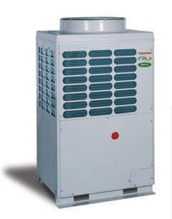
 Twin scroll compressor mounted on sliding tray Individual isolator provided on each unit Model")
67 Outdoor Units Light, compact design with small footprint R407C (HFC) Refrigerant, non-ozone depleting Low sound levels with large diameter stealth fan with streamlined ribs on front edge 20 metre lift capability Energy saving inverter technology with advanced IPDU (Intelligent Power Drive Unit) Twin scroll compressor mounted on sliding tray Individual isolator provided on each unit Model Cooling capacity kw 28.0 Heating capacity kw 31.5 MAR-F 105HTM8-PE Minimum capacity code 2 Maximum capacity code 1 Multi Controller 27 2, 3 or 4 Multi Controllers 32 Power supply V -ph-hz /3/50 Electrical power required at site Three-phase neutral + earth - integral IP 56 isolator Power input, cooling kw 11.8 Power factor, cooling % 98 Running current, cooling A 17.4 Power input, heating kw 10.5 Power factor, heating % 98 Running current, heating A 15.5 Peak demand current A 60 Sound pressure level 1 m 58 Refrigerant type R407C Pipework Suction line O.D. in Brazed - 1-1/8 Liquid line connection, type - O.D. in Flare - 5/8 Discharge line connection, type - O.D. in Flare - 3/4 Maximum equivalent length separation m 120 Maximum actual piping length m 100 Maximum lift Indoor unit above/below m 20/50 Dimensions Footprint mm 990 x 790 Height x width x depth mm 1700 x 990 x 790 Weight kg 285 Finish Silky shade (IY ) Heat exchanger type Finned tube Fan type Sickle-shaped propeller Fan rated air high speed l/s (m 3 /h) 2778 (10000) Compressor type Hermetically-sealed twin scroll Power input kw 7.5 Operating range, cooling/heating C -5 to 43/-15 to
68 Outdoor Units Acoustic Data Sound Power Level Sound Pressure Level k 2 k 4 k 8 k SWL SPL NR Cooling Heating Sound Pressure Level 90 Heating Cooling 80 Sound pressure level (db) NC-60 NC-50 NC-40 NC-30 NC-20 Microphone Position 1m 1.5m Frequency (Hz) 68
69 Outdoor Units Dimensional Drawing MAR-F105HTM8 -PE 4-15 x 20 (Slot) 80 Grounding part of bottom plate Drain opening dimension Fixing bolt positions 80 Grounding part of bottom plate Fixing bolt pitch Foundation dimensions x 150 slot (for transport) Slot pitch Details of piping connections Knock outs on both sides of unit 3-ø 20 cable gland knock outs ø 32 cable gland knock outs ø 25 cable gland knock outs Refrigerant pipe connecting port (Gas suction side) braze connection (ø 28.6) Refrigerant pipe connecting port (Liquid side) flare connection (ø 15.9) Refrigerant pipe connecting port (gas discharge side) flare connection (ø 19.0) Note: All dimensions are in mm
70 Outdoor Units Access and Air Flow to Outdoor Units If the Outer Wall is Higher than the Outdoor Unit If a hole can be made in the wall: Set an aperture ratio so that suction air volume Vs from the hole becomes 1.5 m/s or less 2. Height of discharge duct: HD = H - h 3. Pressure drop of discharge duct to be 15 Pa maximum If a hole cannot be made: (Front side) (Front side) Set a base with 500 to 1000 mm height 2. Height of discharge duct: HD = H - h 3. Pressure drop of discharge duct to be 15 Pa maximum H H HD Discharge duct 1000 Hole in wall Discharge duct h HD h Vs Vs Base Note: All dimensions are in mm
71 Outdoor Units Access and Air Flow to Outdoor Units If the Outer Wall is Lower than the Outdoor Unit 1-line installation (Front side) parallel lines installation * ( 1000) 300 (Front side) parallel lines installation * ( 1000) 300 (Front side) (Front side) * When refrigerant piping is routed from the front of the unit, distance between outdoor unit and connecting piping must be 500 mm or more Note: All dimensions are in mm Connecting Piping Piping 71
72 Outdoor Units Transportation of the Outdoor Unit Fork Lift Front Access insert the forks into the slots on the fixing legs. Side Access see diagram. Front Access Side Access Fork lift Fork lift/ Hand Truck Fixing Leg Crane Check the suitability of the lifting rope (see table). Secure lifting rope through transportation slot. Protect the unit where rope contact could scratch or deform it. Protection Model Number MAR-F-105HTM8-PE Weight 285 kg Rope Protection Transportation Slots 72
73 Multi Controller Installation The three pipes from the outdoor unit are connected to the Multi Controller which then controls the flow of the refrigerant to each of the indoor units. It also acts as a wiring centre for the indoor units, making the provision of a separate power supply unnecessary. The Multi Controllers have three (RBM-Y1034-PE) or four ways ((RBM-Y1044F-PE). Any outlets that are not used can be capped or valved off. Whilst all of the suction pipework within the Multi Controller is insulated to prevent condensation forming, when any unit is cooling, as a precaution a heater element is fitted to the base of the Multi Controller to evaporate any moisture that may collect in the base. This makes the provision of a separate condensate drain unnecessary. As standard, a maximum of two Multi Controllers can be connected to the outdoor unit, however by using the dual interface (RBC-DIF1-PE) this can be increased to a maximum of four. Wiring from two Multi Controllers is taken to the dual interface, and one cable is then taken to the outdoor unit. The location of the Multi Controller should be carefully considered to ensure good all-round access, should any of the valves or sensors require replacing. If the Multi Controllers are to be installed above a false ceiling, then an access panel bigger than the Multi Controller will be required. Precautions Avoid installing the Multi Controller in the following locations: Where rainwater may penetrate the unit. Where the weight of the unit cannot be supported. Where it is not level. Where there is high temperature under the ceiling or where a high-temperature atmosphere may be produced. Where there is equipment that generates high frequencies. Where it is near devices or wiring which may give off electromagnetic interference. The base of the unit will reach temperatures of approximately 50 C. Do not place heat sensitive objects close to the base of the unit. 2 slots for hanging bolts (12 x 52) Electric parts box 2 notches for hanging bolts (12 x 21) 3-pipe: RBM-Y1034F/Y1044F-PE Connection (brazing) Liquid side ø Refrigerant pipe connection (brazing) Liquid side ø 12.7 Wiring knockouts 6 x ø 20 Note: Please instal this way up. Refrigerant pipe connection (brazing) Gas side ø 19 Refrigerant pipe connection (brazing) Suction gas side ø 28.6 Refrigerant pipe connection (brazing) Delivery gas side ø 19 Note: Please instal this way up. Model A B C D E F RBM-Y1034F-PE RBM-Y1044F-PE All dimensions are in mm 73
74 Refrigerant Piping Design Connection to outdoor unit Pipework from the outdoor unit can be routed from the front, side or downwards by removal of the relevant knockout panels. If pipework is routed in front of the outdoor unit, a minimum of 500 mm should be allowed for service access (compressor replacement requires at least 500 mm clearance). Pipework routed forwards Suction valve Shaped pipe section Cut connecting end section Pipework routed downwards Suction valve Cut or debraze L-shaped pipe Braze connecting pipe Remove base plate knock out Pipework routed sideways Suction valve Cut or debraze L-shaped pipe Braze connecting pipe 74
75 Refrigerant Piping Design Allowable Length/Height Difference of Refrigerant Piping Multi Controller Reducer Indoor units SMi outdoor unit T-Piece Multi Controller Indoor units T-Piece Multi Controller Indoor units Type Description Allowable value Reference Length Maximum linear separation - condenser to furthest indoor unit 100 m L1 + L3 + L5 + LI Maximum equivalent resistance - condenser to furthest indoor unit 120 m L1 + L3 + L5 + LI Maximum sub-piping length - from a T-piece to a Multi-Controller or another T-piece 15 m L2, L3, L4, L5 Maximum difference in sub-piping lengths 10 m L2 - L3, L4 - L5 Maximum branch piping length - Multi-Controller to indoor unit 30 m La, Lb, Lc, Ld, Le, Lf, Lg, Lh, L, Lj, Lk, Ll Maximum difference in branch piping lengths from a Multi-Controller 10 m Ld - La, Lh - Le, Ll - Li Height Maximum height difference (drop) - condenser to lowest indoor component 50 m H1 Maximum height difference (lift) - condenser to highest indoor component 20 m H2 Maximum height difference - between any two indoor components 15 m H3 Lm Multi Controller Ln Lo Indoor units Lp Lp1 Lp2 Twinned indoor units H4 13 Type Description Allowable value Reference Length Maximum twinned branch piping length.- Multi-Controller to indoor units 30 m Lp + Lp1 + Lp2 Maximum branch piping length - Multi-Controller to indoor unit 30 m Lm, Ln, Lo Maximum difference in branch piping lengths from a Multi-Controller 10 m (Lp + Lp1 + Lp2) - Lm Maximum side pipe length - T-piece to indoor unit 5 m Lp1, Lp2 Maximum difference in side pipe lengths - T-piece to indoor unit 0.5 m Lp 2 - Lp1 Height Maximum height difference - between twinned indoor units 0.5 m H4 All connections to both outdoor and indoor units are flared except the connections to the outdoor unit and Multi Controller, which are brazed. Oil traps are not required. 75
76 Refrigerant Piping Design Multi-Controller Configurations Number of Multi-Controllers required Dual interfaces required Maximum connected indoor units 3-Way 4-Way capacity code 1 1* * * ** ** ** 12 4 or 3 4 or 3 2 or 1 32** ** ** ** ** * Branches to be capped off as required. ** Any Multi-Controller connected to a Dual Interface has a maximum connected capacity code limit of 13. It may be that site requirements will determine alternative arrangements for a given number of indoor units. For example, if there are four indoor units split across two floors, it may be more convenient for piping purposes to offer a 3-way Multi-Controller for each floor, rather than one 4-way Multi-Controller. Twinning If two identical units are supplying the same space it may be possible to twin the units from one branch of a Multi-Controller. These two units would act as master and slave, sharing control inputs and would therefore both have the same mode, set point, fan speed etc. The capacity code is set using the rotary switches in the respective Multi-Controller as follows: Indoor units Capacity code settings available x RAV-10 No No No No No No No No Yes Yes Yes 2 x RAV-13 No No No No No No Yes Yes Yes No No 2 x RAV-16 No No No No Yes Yes Yes No No No No 2 x RAV-26* No No Yes Yes Yes Yes Yes No No No No 2 x RAV-26 Yes Yes Yes Yes Yes No No No No No No * RAV-265KH & RAV-265NH only Please note that RAV-36 and RAV-46 units cannot be twinned. This is a useful means of reducing the required quantity of Multi-Controllers. For example: If nine indoor units are to be connected to one outdoor unit, but two of those indoor units are supplying the same area, it may be possible to twin the units and install two 4-Way Multi-Controllers, rather than three 3-Way Multi- Controllers. 76
77 Refrigerant Piping Design Pipe Sizes Pipe type Main pipes - P1 Sub-pipes - P2 Branch pipes - P3 RAV-10X = 12.7 mm (1/2 ) ø OD RAV-13X = 12.7 mm (1/2 ) ø OD Gas 28.6 mm (1-1/8 ) ø OD 19 mm (3/4 ) ø OD RAV-16X = 12.7 mm (1/2 ) ø OD RAV-26X = 15.9 mm (5/8 ) ø OD RAV-36X = 19.0 mm (3/4 ) ø OD RAV-46X = 19.0 mm (3/4 ) ø OD RAV-10X = 6.4 mm (1/4 ) ø OD RAV-13X = 6.4 mm (1/4 ) ø OD Liquid 15.9 mm (5/8 ) ø OD 12.7 mm (1/2 ) ø OD RAV-16X = 6.4 mm (1/4 ) ø OD RAV-26X = 9.5 mm (3/8 ) ø OD RAV-36X = 9.5 mm (3/8 ) ø OD RAV-46X = 9.5 mm (3/8 ) ø OD Discharge 19.0 mm (3/4 ) ø OD 15.9 mm (5/8 ) ø OD NOT APPLICABLE Using one Multi Controller SMi outdoor unit P1 Multi Controller P3 P3 Indoor units P3 P3 Using two Multi Controllers SMi outdoor unit P1 Multi Controller P2 P3 P3 Indoor units P3 P3 P2 Multi Controller P3 P3 Indoor units P3 P
78 Refrigerant Piping Design Pipe Sizes Using three Multi Controllers (1 x RBC-16DIF1-PE required) P2 Reducer P1 Multi Controller P3 P3 Indoor units P3 P3 SMi outdoor unit P1 T-Piece Multi Controller P3 P3 P1 P2 Indoor units P3 P3 T-Piece P2 P3 P3 Multi Controller Indoor units P3 P3 Using four Multi Controllers (2 x RBC-16DIF1-PE required) P3 P2 Multi Controller P3 Indoor units P3 P3 P2 T-Piece P3 P3 SMi outdoor unit P1 P1 T-Piece Multi Controller Indoor units P3 P3 P3 P1 Multi Controller P3 Indoor units P3 P2 P3 P2 T-Piece P3 P3 Note: Ensure a minimum of 500 mm of straight piping before any T-piece to ensure equal distribution. 78 Multi Controller Indoor units P3 P3
79 Refrigerant Piping Design Pipe Sizes Twin pipe sizes Pipe type Centre pipes - P4 Side pipes - P5 2 x RAV-10X = 12.7 mm (1/2 ) ø OD RAV-10X = 12.7 mm (1/2 ) ø OD Gas 2 x RAV-13X = 15.9 mm (5/8 ) ø OD RAV-13X = 12.7 mm (1/2 ) ø OD 2 x RAV-16X = 19.0 mm (3/4 ) ø OD RAV-16X = 12.7 mm (1/2 ) ø OD 2 x RAV-26X = 19.0 mm (3/4 ) ø OD RAV-26X = 15.9 mm (5/8 ) ø OD 2 x RAV-10X = 6.4 mm (1/4 ) ø OD RAV-10X = 6.4 mm (1/4 ) ø OD Liquid 2 x RAV-13X = 9.5 mm (3/8 ) ø OD RAV-13X = 6.4 mm (1/4 ) ø OD 2 x RAV-16X = 9.5 mm (3/8 ) ø OD RAV-16X = 6.4 mm (1/4 ) ø OD 2 x RAV-26X = 9.5 mm (3/8 ) ø OD RAV-26X = 9.5 mm (3/8 ) ø OD P3 P3 Multi-Controller P3 Indoor units P4 P5 P5 13 Twinned indoor units 79
80 Refrigerant Piping Design Insulation All piping will need to be thermally insulated with Class O or equivalent, to local regulations and suitable for the ambient temperature experienced. Insulation shall be as follows: Within buildings: Pipe diameter Insulation wall thickness 1/4 to 1/2 9 mm 5/8 to 1-1/8 13 mm Where the discharge pipe is external, a minimum of 25 mm insulation will be required to prevent excessive heat loss through the insulation, resulting in poor heating performance. Where insulated refrigerant pipes penetrate dividing fire-resistant walls and/or ceilings the pipework shall pass through sleeves and the space around the pipes shall be sealed with an approved material to prevent the spread of fire. All external pipework shall be suitably protected from the weather, vermin and UV degradation. Additional Refrigerant The outdoor units are pre-charged with 19 kg of HFC R407C refrigerant. This is suitable for 5 m of main piping (P1). Additional refrigerant will be required as follows - the weight required determined by the length of liquid pipes, in accordance with the table below. Main piping (P1) Sub-piping (P2) Branch piping (P3) 6.4 mm (1/4 ) OD Branch piping (P3) 9.5 mm (3/8 ) OD kg/m kg/m kg/m kg/m For more information on additional refrigerant see the SMi installation manual. 80

81 Controls Introduction The control system that the SMi system is based around, is a serial link that combines communication to the indoor and outdoor units. In the case of SMi system, the network controlling device is connected to the indoor units although existing SMi products can be combined onto the same platform (except for RAV cooling only split systems). The controls may be classified as local or network, and any indoor unit may be controlled by either, or a combination of both (including MMS and RAV 4 and 5 series heat pumps). Local Controls (ABC) Refers to a controller that will normally be used in the conditioned space. Network Controls (XY) These controllers are either centralised for control of a number of indoor units, or a interface which allows connection to the Toshiba Windows control package or another BMS option. For SMi system, the network controls are connected to the indoor units. It is possible to connect the SMi outdoor unit to the network. System Control The system control data is distributed with the power cables from the outdoor unit used in the serial cable, not via a separate network. RBC-SR1 or RBC-SR2 Network control 14 81
82 Controls Local Controls End users can make adjustments to indoor units either individually or in groups of up to 16. Infrared and wired options may be combined with networked controls, to provide local setting, subject to three levels of authority, set from the network. Individual or Group Control All local controls can provide operating instructions to either individual indoor units or groups of up to 16 indoor units. Wired controllers are connected to terminals A-B-C of the appropriate indoor units. RBC-SR1 or RBC-SR2 Up to 16 indoor units When group controlling, terminals B-C are connected throughout the group. All indoor units are provided with the same instructions, however they operate independently to achieve the common set point. Indoor units within a group are addressed by switch 1 (16 position, rotary switch). Jumper CN12 will be removed from slave units. Connected by 3 core cable > 1.0 mm 2. Grouped indoor units, linked by further 2 core cable > 1.0 mm 2. Group wiring can be up to 500 m in length. 82

83 Wired Controller RBC-SR1-PE Controls Local Controls The SR1 allows an interface with a single or a group of up to 16 air conditioners. It allows the user to set all of the operating parameters. It includes a simple lapse timer. It can also be used in conjunction with the RBC-WT1-PE weekly timer. Features: Start/stop control Fan speed (high, medium, low, auto) Set temperature (18 to 29 C) Operating mode fan (cool, heat, auto) Swing louvre (on, off) Filter clean indication Self diagnostic function Group control of 1 to 16 indoor units Elapsed timer on or off function (up to 60 hours) Compatible with RBC-WT1-PE weekly timer 1 or 2 RBC-SR1-PE controllers may serve a group settings changed from either controller Can operate in conjunction with Network controls Network address can be set from controller if required 14 83
 Set temperature (18 to 29 C)")
84 Wired Controller RBC-SR2-PE Controls Local Controls The SR2 allows an interface with a single or a group of up to 16 air conditioners. It allows the user to set all of the operating parameters. It does not contain any timer functionality and is not compatible with the RBC-WT1-PE weekly timer Features: Start/stop control Fan speed (high, medium, low, auto) Set temperature (18 to 29 C) Operating mode fan (cool, heat, auto) Swing louvre (on, off) Filter clean indication Self diagnostic function group control of 1 to 16 indoor units Network address can be set from controller if required Can operate in conjunction with Network controls. 84

85 Weekly Timer RBC-WT1-PE Controls Local Controls The weekly timer is a flexible timer that can be used in a variety of configurations, from connection to the central controllers to the local controllers. The timer is fully-functional and programmable to give flexible time periods as an aid to energy consumption reduction. Manual control functions: Provides up to 2 on/off instructions to RBC-SR1-PE remote or RBC-CR1 64-PE central controller Easy and flexible programming 2 programmes may be set and then selected by a single button Timer enable/disable Local or central override control Auto restart after power failure (if required to operate) 72 hour re-chargeable battery RBC-SR1-PE RBC-WT1-PE 14 Network control Connected to RBC-SR1-PE or RBC-CR64-PE (terminals A-B-D) by 3 core cable >1.0 mm 2. Wiring can be up to 10 m in length. 85

86 Infra-red Controller RBC-IR2-PE Controls Local Controls The infra-red remote controller allows control of all unit functions without the requirement of a wall controller. 4 styles of indoor unit are available with the alternative controller: RAV-UH RAV-KH RAV-SH RAV-CH 4 way cassette high wall low wall ceiling Features: Start/stop control Fan speed (high, medium, low, auto) Set temperature (18 to 29 C) Operating mode (cool, heat, fan only) Swing louvre (on, off) Filter clean indication Self diagnostic function (unit #1) Instructions transmitted to group of between 1 and 16 indoor units Can operate in conjunction with Network controls. Grouped indoor units, linked by 2-core screened cable > 1.0 mm 2. Group wiring can be up to 500 m in length. 86
87 Controls Network Control A group of controls that will generally be located away from the air conditioned environment. Toshiba offers a wide range of products to control the air conditioning. These products are: Central remote controller LonWorks gateway Windows control package Remote monitoring and control via Internet Energy monitoring Refrigerant detection RBC-WT1-PE RBC-SR1-PE Network control 14 87

88 Central Controller RBC-CR64-PE Controls Network Control Provides instructions to a network of up to 64 zones, any of which can include up to 16 grouped indoor units. Up to 1024 indoor units may be controlled in this way. Manual control functions: Zones can be instructed either individually or simultaneously Indoor units may be grouped into zones One or two central controllers may be applied to a network Start/stop control Fan speed (high, medium, low, auto) Set temperature (18 to 29 C) Operating mode (cool, heat, auto) Swing louvre (on, off) Filter clean indication Self diagnostic function Local control can be provided to any or all zones by either RBC-SR1-PE or RBC-SR2-PE wired controllers. Three levels of authority available from central controller: - Last touch priority - Start/stop control only settings only from central controller - Indoor unit locked off Where a wired remote controller is used, a group of up to 16 indoor units may be created. May control indoor units within multiple systems Can operate in conjunction with RBC-WT1-PE weekly timer Indoor unit association with central timer function is optional Indoor unit operation may be terminated collectively by an emergency input (e.g. fire alarm). A normally closed pair of terminals is available for this purpose. Connected to master indoor unit by 2- core screened cable, >1.0 mm 2, which can be up to 1000 m in length. 230 V ac single phase power supply, sourced locally, supplied to external power unit. 88
 Fan speed (high, medium, low, auto) Start/stop control Set temperature (18 to 29 C) Swing louvre (on, off) Self diagnostics Last touch")
89 Windows Gateway RBC-WG1-PE Controls Network Control Allows up to 64 indoor units to be controlled per Windows gateway. Features available: Operating mode (Auto, cool, heat, fan only) Fan speed (high, medium, low, auto) Start/stop control Set temperature (18 to 29 C) Swing louvre (on, off) Self diagnostics Last touch priority RBC-SR1-PE RBC-WG1-PE Network control Computer running RBC-WP1-PE software package Note: Software power supply required for interface. Local control can be provided to any or all zones by either RBC-SR1-PE or RBC-SR2-PE wired controllers. - Last-touch priority - Start/stop control only settings only from administrator - Indoor unit locked off Where a wired remote controller is used, a group of up to 16 indoor units may be created (network can include up to 1024 indoor units) 14 May control indoor units within multiple systems 1 or 2 RBC-SR1-PE controllers may serve a group settings changed from either controller Sensor data sent to gateway Connected to master indoor unit by 2-core screened cable > 1.0 mm 2, which can be up to 1000 m in length. 230 V ac single phase power supply, sourced locally. 89

90 Controls Network Control Analogue BMS Interface RBC-BG1-PE The BG1 allows up to 16 groups or individual indoor units to be controlled under the same operating parameters. The controller will display the fault condition of the connected units locally and alert the BMS of any faults via a volt-free contact. The instructions are provided via 4 analogue, 0 to 10VDC outputs from the Building Management System. Operating mode heat, cool, fan, off Fan speed high, medium, low, auto Louvre control on or off Set temperature 18 to 29 C RBC-SR1-PE RBC-BG1-PE Network control Note: Software power supply required for interface. BMS system Other features All or some inputs can be manually set LCD display Common alarm relay - normally open volt-free contacts LEDs showing operating and communication status 90
91 Controls Network Control Fan Speed Settings Operating mode Volts 4 Volts Auto Low Set temperature Fan speed Med High 0 Off Fan Only Auto Cool Heat Reset Louvre operation Volts 6 4 Volts off on C Louvre setting Connected to inverter outdoor unit by 2-core screened cable >1.0 mm 2, which can be up to 1000 m in length. 230 V ac single phase power supply, sourced locally
92 Controls Network Control Interactive Intelligence The software allows full control of up to 1024 individual indoor units through a maximum of 16 RBC-WG1- PE gateways.there are various further options for energy monitoring and access to the system via the company s intra/extranet. Windows Control RBC-WP1-PE The Windows package is used with all of the options for energy monitoring and internet access. The Windows package consists of a network card, CD and hardware dongle. When the software is installed it recognises the number of RBC-WG1-PEs and the number of indoor units generating standard schematics. The key features are listed below: Automatic configuration Unit locations can be displayed via site specific floor plans All unit settings can be made Diagnostics Alarms transmitted by: Fax SMS Modems Pager Operating data can be stored Multiple time schedules Intelligent optimum start Up to 16 gateways can be connected to the computer Minimum system requirements: Pentium 3 or equivalent processor (700 MHz) 256 MB RAM (500 MB RAM if using energy monitoring) Hard drive with 50MB free space 16 bit High Colour 800 x600 SVGA or greater display Win 95, Release 2 or later Win NT, Version 4.0 or later (service pack 3.0 or greater) 92
.")
93 Controls Network Control Internet Kit RBC-IK1-PE The internet kit is an optional piece of software that can be used with the RBC-WG1-PE and the RBC- WP1-PE (through any PC connected to the Windows gateways and the internet). Ideal for building management with more than one site it provides: Remote control access for multiple users at any one time, using Microsoft Internet Explorer Two levels of control: - Monitoring - Full control Immediate access to operating conditions and historical performance, facilitating rapid response to customer enquiries Five concurrent users (five people can be connected at the same time) Energy Monitoring RBC-EM1-PE The energy monitoring kit is a power meter that monitors the actual power that is consumed by up to two outdoor units. The kit consists of the meter and a set of current transformers that are placed on the supply cables to the outdoor units. RBC-SR1-PE Network control RBC-EM1-PE Power supply V 14 Records power consumption by indoor unit or group The software is included in the Windows package Bill reports can be generated to specific requirements Option to export data to billing software or external site 93
TOSHIBA AIR CONDITIONING
 Digital Inverter Standard Specification R32 Introduction The following specification describes the Toshiba Digital Inverter Heat Pump air conditioning system(s) to be installed at the below site: (ADD
SERVICE MANUAL AIR CONDITIONER SPLIT TYPE
 FILE No. A90-961 SERVICE MANUAL AIR CONDITIONER SPLIT TYPE WAY CASSETTE TYPE RAV-133TU-PE/RAV-13A-PE RAV-163TU-PE/RAV-18A-PE Printed in UK Dec 1996 s CONTENTS 1. SPECIFICATION...3. CONSTRUCTION VIEWS...5
AIR-CONDITIONER TOSHIBA SERVICE MANUAL SPLIT TYPE, HEAT PUMP COOLING ONLY FILE NO. A Tel: Fax:
 Tel: 08 0 www.heronhill.co.uk Fax: 08 80 TOSHIBA Heronhill - for all your Toshiba requirements FILE NO. A90-00 SERVICE MANUAL AIR-CONDITIONER SPLIT TYPE, HEAT PUMP COOLING ONLY WAY CASSETTE TYPE RAV-0TUH--PE
Inventor of the Inverter Digital Inverter System
 Inventor of the Inverter Digital Inverter System Inventor of the Inverter The Digital inverter from Toshiba combines economy and ecology in a smart body. It offers state-of-the-art technology, exceptional
System architecture. Air treatment Index
 System architecture Air treatment Index 88 Index Chilled-water air treatment units Type Range Cooling capacity, kw Heating capacity, kw Air flow, l/s Chilled-water terminal units Cassette Cabinet Concealed
Digital Inverter 4 series 8 & 10HP
 E6-H Digital Inverter 4 series 8 & 0HP High static duct type Indoor unit RAV-SM2244DTP-E RAV-SM2804DTP-E Outdoor unit RAV-SM2244AT8-E RAV-SM2804AT8-E Contents. Line up... 2. Indoor unit (High static duct
Business. The business range. The most advanced solutions for larger buildings.
 Business The business range The most advanced solutions for larger buildings. 81 82 Business VRF. The freedom of choice Variable refrigerant flow offer the advantages of direct expansion linked to inverter
4-Way Cassette type. Contents MMU-AP 2H2UL
 E15-3C1 6 Indoor unit MMU-AP 2H2UL 4-Way Cassette type MMU-AP0072H2UL MMU-AP0092H2UL MMU-AP0122H2UL MMU-AP0152H2UL MMU-AP0182H2UL MMU-AP0212H2UL MMU-AP0242H2UL MMU-AP0302H2UL MMU-AP0362H2UL MMU-AP0422H2UL
Heat Pump Air Conditioning Systems
 Heat Pump Air Conditioning Systems Create your own Utopia. In a climate as diverse as ours air conditioning your premises can make a huge difference to the comfort of your staff, and your customers too.
AIR-CONDITIONER SERVICE MANUAL
 FILE NO. A90-9608 SERVICE MANUAL AIR-CONDITIONER S SPLIT BUILT-IN DUCT TYPE RAV-362B-PE/ RAV-462B-PE/ SPLIT CEILING TYPE RAV-362C-PE/ RAV-462C-PE/ SPLIT CASSETTE TYPE RAV-362U-PE/ RAV-462U-PE/ PRINTED
3 rd Generation of VRV. The professional solution for your professional project
 3 rd Generation of VRV The professional solution for your professional project CONTENT What is VRV? Definition, History, Concept VRVIII Range Outdoor units, indoor units. VRVIII features Piping limits,
INVERTER DUCTED SYSTEMS
 INVERTER DUCTED SYSTEMS What you ll find inside: DC Twin-Rotary Compressor Inverter Ducted advantages Controllers Product Specifications Energy Efficient Powerful Operation Flexible Application 1 About
Artus by. A smarter, more compact approach to air conditioning
 Artus by A smarter, more compact approach to air conditioning There s a way to do it better - find it. Thomas A. Edison Why do we put up with products that don t work properly? The problems with existing
Technical Selection. elevent ceiling diffusers. Swirl, Jet, Louvred and Curved ceiling diffusers
 elevent ceiling diffusers Technical Selection Swirl, Jet, Louvred and Curved ceiling diffusers Paltech elevent Ceiling Diffusers are protected by: Australian Patent 0179430 + other patents pending Australian
SIMPLICITY OR FULL MODULARITY?
 D E S I G N I N G I N N O V A T I V E S O L U T I O N S AIR CONDITIONING & HEATING SOLUTIONS SIMPLICITY OR FULL MODULARITY? IDROFAN, BECAUSE YOU SHOULD NOT HAVE TO CHOOSE. Hydronic ducted fan coils Cooling
Primo Hotel. General. Indoor climate units for hotel rooms
 Indoor climate units for hotel rooms General Primo Hotel indoor climate unit Ceiling-mounted indoor climate units for ventilation, cooling and heating High capacity; occupies little space Dry system without
Fan Coil Unit 1. BOSCH Climate Fan Coil Unit
 Fan Coil Unit 1 BOSCH Climate 000 Fan Coil Unit 2 Fan Coil Unit Introduction to Bosch Thermotechnology Bosch Thermotechnik GmbH is a leading supplier of resourceefficient heating products and hot water
Technology that works fast. Inverter Ducted Systems
 Technology that works fast Ducted Systems About Toshiba s Ducted systems. Combining high power with high efficiency. Toshiba s Ducted systems allows you to air The Toshiba Air Conditioning DC Hybrid. The
AIR HANDLING UNITS ASSET REFERENCE: DESIGN AHU 1 AHU 2
 AIR HANDLING UNITS DESIGN System INFORMATION No off Access Handing Viewed in direction of supply air Finish / Colour Duct Connections Height: Width Velocity: Design Airflow (m3/s) Supply Fan Ability Supply
Technology that works fast. Inverter Ducted Systems
 Technology that works fast Inverter Ducted Systems About Toshiba s Inverter Ducted systems. Toshiba s Inverter Ducted systems allows you to air condition your home without having to install the indoor
Technology that works fast. Inverter Ducted Systems
 Technology that works fast Inverter Ducted Systems About Toshiba s Inverter Ducted systems. Toshiba s Inverter Ducted systems allows you to air condition your home without having to install the indoor
VRF Series. The most advanced commercial air conditioning system
 VRF Series The most advanced commercial air conditioning system 4 The most advanced commercial air conditioning solution As a world-wide leader in electronics Toshiba not only develops new technologies
Installation Operation Maintenance. Ductable water unit FWD FWD-SVX01D-E4
 Installation Operation Maintenance Ductable water unit FWD 08-12 - 20-30 - 45 General Information Foreword These installation, operation and maintenance instructions are given as a guide to good practice
2.0 kw 35 C 65 C AQUAREA AIR RADIATORS
 AQUAREA AIR RADIATORS New line up of Super low temperature radiators for Heat Pump application: Aquarea Air 00/700/900 with radiating effect The slimline Panasonic Aquarea Air radiators deliver high efficiency
TOSHIBA AIR CONDITIONING. TOSHIBA Super Heat Recovery Multi System Standard Specification
 Introduction The following specification describes the Toshiba 3-Pipe Super Heat Recovery Multi air conditioning system(s) to be installed at the below site: (ADD SITE NAME) The system(s) shall consist
technical data air conditioning systems FDKS-CVMB Concealed ceiling, Inverter Controlled Unit Split Sky Air
 technical data FDKS-CVMB Concealed ceiling, Inverter Controlled Unit air conditioning systems Split Sky Air Indoor Units R410A FDKS-CVMB TABLE OF CONTENTS FDKS-CVMB 1 Features.............................................................
Blending Commercial and Residential. MiNi VRF
 Blending Commercial and Residential MiNi VRF Toshiba Solutions Delivering Absolute Comfort Toshiba offers a solution for all applications: residential, light commercial and larger commercial buildings.
Compact 4-way Cassette ( ) Type
 Type") E08-0 Engineering Data Compact 4-way Cassette (600 600) Type Indoor Unit RAV-SM40MUT-E RAV-SM4MUT-E Outdoor Unit RAV-SP404AT-E RAV-SP44AT-E Contents. Specifications. Connecting pipe length and lift difference
E08-0 Engineering Data Compact 4-way Cassette (600 600) Type Indoor Unit RAV-SM40MUT-E RAV-SM4MUT-E Outdoor Unit RAV-SP404AT-E RAV-SP44AT-E Contents. Specifications. Connecting pipe length and lift difference
Concealed ceiling unit with medium ESP
 FXSQ-A Concealed ceiling unit with medium ESP Slimmest yet most powerful medium static pressure unit on the market Slimmest unit in class, only 245mm (3mm built-in height) and therefore narrow ceiling
EHH SERIES DRAW THROUGH FAN COILS CFM
 EHH SERIES DRAW THROUGH FAN COILS 400-5000 CFM TABLE OF CONTENTS TABLE OF CONTENTS 2 INTRODUCTION 3 GUIDE SPECIFICATIONS 4 UNIT OVERVIEW 6 TECHNICAL DATA 8 DIMENSIONS 10 COMPUTER SELECTION 11 GEMCOOL PROFILE
INTRODUCTION Flexibility Is The Key Simple Access For Maintenance
 Cougar Energy efficient slimline 180mm fan coil unit Chilled water cooling & hot water heating Waterside control with variable air volume Commercially quiet with excellent acoustics Programmable communicating
Panther Fan Coil Unit
 Panther Fan Coil Unit Energy Efficient EC Motors 280mm Deep Chassis Horizontal Fan Coil Unit INTRODUCTION The Panther, manufactured by Dunham-Bush is an adaptable, easy to use fan coil unit, that performs
SIMPLICITY FULL MODULARITY?
 D E S I G N I N G I N N O V A T I V E S O L U T I O N S AIR CONDITIONING & HEATING SOLUTIONS OR SIMPLICITY FULL MODULARITY? IDROFAN, BECAUSE YOU SHOULD NOT HAVE TO CHOOSE. Hydronic ducted fan coils Cooling
MODEL: ACWD CEILING CONCEALED Chilled Water Fan Coils Unit
 MODEL: ACW200D ACW300D ACW400D ACW500D ACW600D ACW800D ACW900D ACW1000D ACW1200D ACW1400D ACWD-2006 ACWD_2006_Cover.indd 1 CEILING CONCEALED Chilled Water Fan Coils Unit 2006-5-25 17:24:07 Contents Main
DERV / ERV DEHUMIDIFICATION & ENERGY RECOVERY V E N T I L A T O R U N I T S I N N O V AT I O N W I T H S T Y L E
 DERV / ERV DEHUMIDIFICATION & ENERGY RECOVERY V E N T I L A T O R U N I T S I N N O V AT I O N W I T H S T Y L E INTRODUCTION DERV/ERV Introduction Dehumidification & Energy Recovery Ventilator DERV units
PRODUCT LINEUP VRF. For LIGHT COMMERCIAL & RESIDENTIAL, COMMERCIAL
 PRODUCT LINEUP VRF For LIGHT COMMERCIAL & RESIDENTIAL, COMMERCIAL 100 AIRSTAGE VRF Systems can be designed to create an air conditioning solution to suit most building requirements. AIRSTAGE VRF Systems
SMC DUCTED. High Performance AIR CONDITIONING SYSTEMS
 SMC DUCTED High Performance AIR CONDITIONING SYSTEMS NEW SLIM DUCTED SYSTEM h 220 mm 1 Slim and compact The new SMC Ducted system is just 220mm in height for sizes up to 5.94 kw and 310mm for larger systems,
FUJITSU VRF 2016/17 PRODUCT CATALOGUE VRF MULTI SPLIT VRF VENTILATION
 FUJITSU VRF PRODUCT CATALOGUE 2016/17 VRF VENTILATION SPLIT MULTI SPLIT VRF VENTILATION SUPPORT Design Simulator Automatically create model selection information Each unit can be automatically set by entering
Ducted Air Conditioning
 Ducted Air Conditioning Why Choose Mitsubishi Electric? Whether it is consistent heating and cooling for the home or office, Mitsubishi Electric offers you state-of-the-art technology that is quiet, simple
Inventor of the Inverter
 Inventor of the Inverter MiNi-SMMS WHEN COMMERCIAL MEETS RESIDENTIAL COST SAVING INSTALLATION R410A HIGH EFFICIENCY HIGH RELIABILITY QUIET OPERATION SMALL AND LIGHTWEIGHT Model Type Model Name Capacity
Ducted Air Conditioning
 Ducted Air Conditioning Why Choose Mitsubishi Electric? Whether it is consistent heating and cooling for the home or office, Mitsubishi Electric offers you state-of-the-art technology that is quiet, simple
Advance Product Data. Features/Benefits. 42WKN Hydronic Fan Coil Units
 Advance Product Data 42WKN Hydronic Fan Coil Units 3 4 to 2 1 2 Tons UNIT SIZES 004-010 UNIT SIZES 016,020 The new Carrier Hydronic Cassette offers a modern solution for a wide variety of small and medium
technical data air conditioning systems FDXS-CVMB Concealed Ceiling, Inverter Controlled Unit Split Sky Air
 technical data FDXS-CVMB Concealed Ceiling, Inverter Controlled Unit air conditioning systems Split Sky Air Indoor Units R410A FDXS-CVMB TABLE OF CONTENTS FDXS-CVMB 1 Features.............................................................
Innovative air conditioning
 Innovative air conditioning No external condensers or pipework Easy installation Discreet external grilles Quiet, high efficiency operation In exclusive partnership with Olimpia Splendid, one of Europe
Residential and Light Commercial Ductless Systems Catalog
 Residential and Light Commercial Ductless Systems Catalog May 2018 Table of Contents Midea Global 3 Ductless Benefits 5 Single and Multi-Zone Solutions 9 Single Zone Residential 13 Max Series 15 Advantage
DESIGN & TECHNICAL MANUAL
 AIR CONDITIONER Wall mounted type DESIGN & TECHNICAL MANUAL INDOOR ASYG07KGTA ASYG09KGTA ASYG12KGTA ASYG14KGTA OUTDOOR AOYG07KGCA AOYG09KGCA AOYG12KGCA AOYG14KGCA DR_AS049EF_02 2017.10.11 Notices: Product
Compact Design For Light Commercial Buildings. Benefit Points SMALL OFFICES HOTELS NEW SHOPS, RESTAURANTS. 1. Compact & Quiet design
 VRF system for medium sized buildings SMALL OFFICES Compact Design For Light Commercial Buildings Perfect total air conditioning systems with features of energy saving, low noise, comfortable airflow,
Technical Guide. Multizone: Multi-Split Type Heat Pump Systems
 Technical Guide Multizone: Multi-Split Type Heat Pump Systems 1 Another Hitachi Day 1 Wall Mounted (RAK) Imagine choosing your perfect day then instantly creating it in the comfort of your own home. With
technical data Fan coil unit FWB small duct unit
 technical data Fan coil unit FWB small duct unit TABLE OF CONTENTS FWB 1. Nomenclature ---------------------------------------------------------------------- 2 2. Features -----------------------------------------------------------------------------
MiNi-SMMS Design Manual HFC R-410A. Indoor unit. Outdoor unit
 Ref.-No. SMME06-111-10-06 MiNi-SMMS Design Manual Indoor unit 4-way ceiling cassette MMU-AP0091H, AP0121H, AP0151H, MMU-AP0181H, AP0241H, AP0271H, MMU-AP0301H, AP0361H, AP0481H Compact 4-way ceiling cassette
Modular Air Cooled Scroll Chillers
 Modular Air Cooled Scroll Chillers 65 80 130 Find out more at www.greeonline.com 160 249 High Efficiency Shell and Tube Heat Exchanger The Gree D Series Chillers utilise high efficiency shell and tube
30RB Air-Cooled Liquid Chillers PRODUCT SELECTION DATA. Easy and fast installation. Compact, reliable and efficient
 PRODUCT SELECTION DATA Easy and fast installation Compact, reliable and efficient Class A variable speed circulator available Air-Cooled Liquid Chillers 0RB 008-015 CARRIER participates in the ECP programme
V ~, 50Hz 1Ph. High Wall Split Systems Heat Pump 9K - 12K - 18K - 24K - 28K. Auto. Auto Fan Speed. Auto. Smart LCD Wireless Control.
 HFC4 1 0 A 0-40V ~, 0Hz 1Ph High Wall Split Systems Heat Pump 9K - 1K - 18K - 4K - 8K R-410A Compressor Super Quiet AMS Anti-dust Filters Auto Fan Speed Timer Functions Defrost Protection Smart LCD Wireless
360 round flow, ensuring uniform airflow distribution across the room. Independent louvre control allows each louvre to be set at the desired angle
 AUTO ILLE ELEVATION GR ED CAN BE LOWER UP TO 4M Better Design Super slim design, perfect for tight roof spaces 360 round flow, ensuring uniform airflow distribution across the room Independent louvre control
30RB Air-Cooled Liquid Chillers. Nominal cooling capacity 8-14 kw. Features. Quiet operation
 Air-Cooled Liquid Chillers www.eurovent-certification.com www.certiflash.com Quality Management Systems 0RB 008-05 Nominal cooling capacity 8- The new generation of Aquasnap liquid chillers was designed
A GUIDE TO COMFORT EXCLUSIVELY DISTRIBUTED BY TEMPERZONE AUSTRALIA
 A GUIDE TO COMFORT HITACHI INVERTER SPLIT SYSTEMS Enjoy the Silence with Quiet Mode With Hitachi, noisy air conditioners are a thing of the past. Our modern Full Flat design has ensured efficient yet ultra-quiet
iq Star LYRA II chilled beam cassette
 iq Star LYRA II chilled beam cassette Key features Ventilation Heating and cooling Compact chilled beam Adjustable induction Flow Pattern Control Integrated control In option: Demand Controlled Ventilation,
Index. Toshiba Solutions. Absolute comfort
 2 3 Index Introduction 3 Industry leading energy savings 6 New smart & sensitive VRF control 10 Industry leading layout flexibility 14 Other features 18 Outdoor units Outdoor units line-up 20 Outdoor units
Energy-saving operation
 DC Inverter can attain both comfort a Energy-saving operation All the models of Panasonic FS Inverter Series are equipped with DC inverters for the higher EER operation. The new design attains quiet and
DESIGN & TECHNICAL MANUAL
 AIR CONDITIONER Wall Mounted type DESIGN & TECHNICAL MANUAL INDOOR AS A09LEC AS A12LEC OUTDOOR AO R09LECN AO R12LECN 1.INDOOR UNIT : AS A09LEC AS A12LEC DTR_AS047E_01 2010.10.05 1. INDOOR UNIT CONTENTS
Inverter Ducted Air Conditioners
 Inverter Ducted Air Conditioners About Carrier Inverter Ducted Systems Carrier s Inverter Ducted systems allows you to air condition your home without having to install the indoor units on your wall, making
technical data air conditioning systems FHYCP-B7 4-way Blow Ceiling Mounted Cassette (950x950) Split Sky Air
 Split Sky Air") technical data FHYCP-B7 4-way Blow Ceiling Mounted Cassette (950x950) air conditioning systems Split Sky Air Split - Sky Air ISO400 assures an effective environmental management system in order to help
technical data FHYCP-B7 4-way Blow Ceiling Mounted Cassette (950x950) air conditioning systems Split Sky Air Split - Sky Air ISO400 assures an effective environmental management system in order to help
LIGHT COMMERCIAL RANGE Inverter heat pumps suitable for both homes and commercial premises
 LIGHT COMMERCIAL RANGE Inverter heat pumps suitable for both homes and commercial premises Toshiba Heat Pumps. We care about better air. Toshiba was the first company to incorporate inverter technology
PMFY-P-VBM-E. Ceiling cassette (1-way flow type) R410A Data G8 1. SPECIFICATIONS EXTERNAL DIMENSIONS CENTER OF GRAVITY 1-100
 R410A Data G8 1. SPECIFICATIONS EXTERNAL DIMENSIONS CENTER OF GRAVITY 1-100") Ceiling cassette (-way flow type) RA Data G8 -P-VBM-E. SPECIFICATIONS - 98. EXTERNAL DIMENSIONS - 99 3. CENTER OF GRAVITY -. ELECTRICAL WIRING DIAGRAMS -. SOUND LEVELS -. Sound levels -. NC curve 6. TEMPERATURE/AIRFLOW
Ceiling cassette (-way flow type) RA Data G8 -P-VBM-E. SPECIFICATIONS - 98. EXTERNAL DIMENSIONS - 99 3. CENTER OF GRAVITY -. ELECTRICAL WIRING DIAGRAMS -. SOUND LEVELS -. Sound levels -. NC curve 6. TEMPERATURE/AIRFLOW
BRT C/H Series PACKAGED AIR TO AIR UNITS COOLING / HEATING APPLICATIONS OUTDOOR INSTALLATION. Ver. 1.01
 b cool manufacturers of air-conditioning equipment ltd BRT C/H Series PACKAGED AIR TO AIR UNITS COOLING / HEATING APPLICATIONS OUTDOOR INSTALLATION Ver. 1.01 Ver. 3.02 01_18 BCool# 1 brt c/h r407c / r410a
Part 1 General Information... 1 Part 2 Indoor Units... 7 Part 3 Outdoor Units Part 4 Installation Part 5 Control...
 MCAC-UTSM-2008-11 Contents Part 1 General Information... 1 Part 2 Indoor Units... 7 Part 3 Outdoor Units... 88 Part 4 Installation... 127 Part 5 Control... 136 The specifications, designs, and information
Light commercial range. Passion at work. Light commer
 Light commercial range Passion at work Light commer Index Introduction and technology 4 Outdoor unit 8 Indoor units and controls 10 Product pages Super Digital Inverter 4 outdoor unit 16 Super Digital
Light commercial range. Passion at work
 Light commercial range Passion at work 2 Light Commercial Solutions for professionals, from professionals Toshiba-Carrier Super Digital Inverter systems deliver exceptional operating savings in extremely
Toshiba s new VRF breaks ground for efficiency, Continuous heating and hands-free commissioning
 As a world leader in electronics, Toshiba is committed to delivering the highest standards of quality and innovation. Toshiba set the benchmark in energy efficiency with significant technological advances
MiNi-SMMS WHEN COMMERCIAL MEETS RESIDENTIAL
 MiNi-SMMS WHEN COMMERCIAL MEETS RESIDENTIAL 2 Toshiba solutions residential, light commercial and larger commercial buildings. Residential indoor units are designed to blend perfectly with all interiors
If a peak space temperature to about 28ºC is acceptable to the occupants then a naturally ventilated solution is a viable option.
 Air handling units Aesthetic Not to add significantly to the existing ambient noise levels. Functional requirements If a peak space temperature to about 28ºC is acceptable to the occupants then a naturally
KLIMA Active Chilled Beams
 KLIMA 2 600 Active Chilled Beams Index Subject Page Index 1 Introduction 2 General description 3-4 Product features 5-6 Dimensions 7 Performance data 8-11 Section example Guide specifications 13 1 Introduction
THE CARRIER COMFORT LINE
 SPLIT SYSTEM SPLIT SYSTEM AIR/AIR TECH 2000 38 TUA/38 CKX 38 YCX - FB4 ASX THE CARRIER COMFORT LINE OUTDOOR UNIT THE ROAD TO All the materials used are designed and protected to resist the toughest climates:
DUCTED. SYSTEMS Enhanced for superior comfort and smart energy management by AirTouch 3. fordanddoonan.com.au 1800 AIR CON
 * H E A T I N G & C O O L I N G DUCTED SYSTEMS Enhanced for superior comfort and smart energy management by AirTouch 3. Mobile device not included * Terms and Conditions apply. See back cover for details.
Product Data. 38GJQ MULTI-ZONE DUCTLESS SYSTEM MATCHED WITH 40GRQ / 40GJB / 40GJC / 40GJD / 40GJF Indoor Units Sizes 18, 24, 30, 36, 42, 48 and 56
 38GJQ MULTI-ZONE DUCTLESS SYSTEM MATCHED WITH 40GRQ / 40GJB / 40GJC / 40GJD / 40GJF Indoor Units Sizes 18, 24, 30, 36, 42, 48 and 56 Product Data INDUSTRY LEADING FEATURES / BENEFITS AN INEXPENSIVE AND
SPECIFICATIONS CWC - 2P / 4P CWC 020 CWC 030 CWC 040 CWC 050 CWC 070 CWC
 APPLICATION GUIDE CHILLED WATER CASSETTE CWC - P/4P English/03-005 INDEX Index AGU CWC-P/4P General Description Specifications Performances tables Sound levels Options Dimensions Unit installation Electrical
Commercial Air Conditioners. VRF 60Hz V4+S/V4+R/V4+W/Mini VRF
 2016 Commercial Air Conditioners VRF 60Hz V4+SV4+RV4+WMini VRF OUTDOOR UNIT LINEUP INDOOR UNIT LINEUP 1.8 2.2 2.8 3.6 4.5 5.6 7.1 8.0 9.0 10.0 11.2 12.5 14.0 16.0 20.0 25.0 28.0 40.0 45.0 OUTDOOR UNIT
S Y D. HWP 35, 47, 58 (c/w EC Motor & UC7 Controller) Ducted Water Cooled R410A Packaged Air Conditioner. Installation & Maintenance
 Ducted Water Cooled R410A Packaged Air Conditioner. Installation & Maintenance") HWP 35, 47, 58 (c/w EC Motor & UC7 Controller) Ducted Water Cooled R410A Packaged Air Conditioner Installation & Maintenance Fig. 1 Nomenclature Nomenclature e.g. H W P 3 5 C K Series Size Type S Y D GENERAL
HWP 35, 47, 58 (c/w EC Motor & UC7 Controller) Ducted Water Cooled R410A Packaged Air Conditioner Installation & Maintenance Fig. 1 Nomenclature Nomenclature e.g. H W P 3 5 C K Series Size Type S Y D GENERAL
Multi Air Conditioning System for Buildings
 Multi Air Conditioning System for Buildings Large Capacity Multi VRF System DC Inverter Control Compressor Long Piping System Design High Efficiency Refrigerant R410A All for Comfort Smart and cutting
EREBA ACCESS. Easy and fast installation Hydronic module available Compact, reliable and efficient USE RANGE CONFORMITY
 Easy and fast installation Hydronic module available Compact, reliable and efficient Nominal cooling capacity : 8-40 kw Nominal heating capacity : 17-40 kw 50 410A Cooling or heating USE The air-to-water
TCB-DP22CUL. Drain Pump Kit. Model name : AIR CONDITIONER (SPLIT TYPE) Installation Manual. Installation Manual 2 Air Conditioner (Split type) English
 Installation Manual. Installation Manual 2 Air Conditioner (Split type) English") AIR CONDITIONER (SPLIT TYPE) Model name : TCB-DP22CUL 2 Air Conditioner (Split type) English Manuel D installation Climatiseur (Type split) 12 Français Please read this carefully before installing the
AIR CONDITIONER (SPLIT TYPE) Model name : TCB-DP22CUL 2 Air Conditioner (Split type) English Manuel D installation Climatiseur (Type split) 12 Français Please read this carefully before installing the
The new Xcell EC High Efficiency Range Fresh air pure and simple
 The new Xcell EC High Efficiency Range Fresh air pure and simple The new Xpelair saving energy, saving money 2 www.xpelair.co.uk Introducing the NEW Xpelair Xcell EC High Efficiency range. The Xcell EC
Technical Data ISU Series. Underceiling/Console Split System Air Conditioners kw 15 kw
 Underceiling/Console Split System Air Conditioners Technical Data ISU Series Featuring SAT- Controller & Long Life Epoxy Coated Outdoor Coil Nominal Cooling Capacity 13. kw 15 kw NOVEMBER 0 ISU SERIES
Fully Flat Cassette Design & Genius in one
 ARGUE CARDS Fully Flat Cassette Design & Genius in one Why choose fully flat cassette Unique design in the market that integrates fully flat into the ceiling Advanced technology and top efficiency combined
Air Conditioning For Large Buildings
 Air Conditioning For Large Buildings Index Introduction 2 Line-up 16 Outdoor SMMS-i specifications 20 Indoor 4-way cassette 22 Compact 4-way cassette 24 2-way Air Discharge Cassette Type 26 1-way cassette
Technical Data OPA RKTBG-P. Ducted Three Phase Packaged Air Conditioners. 47 kw 96 kw
 Ducted Three Phase Packaged Air Conditioners Technical Data 96 RKTBG-P Plug Fan with High Efficiency EC Motor and High External Static Economiser Option TZT Controller & Digital Scroll Compressor for close
DESIGN & TECHNICAL MANUAL
 AIR CONDITIONER Wall mounted type DESIGN & TECHNICAL MANUAL INDOOR ASYG18KLCA ASYG24KLCA OUTDOOR AOYG18KLTA AOYG24KLTA DR_AS069EF_01 2018.03.16 Notices: Product specifications and design are subject to
Units for suspended ceilings
 X X testregistrierung Units for suspended ceilings Type, hinged induced air grille, water connections Active chilled beam with two-way air discharge and horizontal heat exchanger, suitable for grid ceilings
Fresh air unit ALB. ALB it s simple and so easy! Air supplied through a heater and filter in a single unit.
 Fresh air unit ALB ALB it s simple and so easy! Air supplied through a heater and filter in a single unit. The ALB fresh air units from Helios provide comfortable room temperatures. Fresh outside air is
Product Data Split System (R-410A) Air Handler for Multi Split Inverter System 9,000 to 24,000 BTU/Hr
 Air Handler for Multi Split Inverter System 9,000 to 24,000 BTU/Hr") Product Data -188-05 Split System (R-10A) Air Handler for Multi Split Inverter System 9,000 to,000 BTU/Hr Ceiling Concealed Type Indoor Unit: MXD8509A10N0 MXD851A10N0 MXD8518A10N0 MXD851A10N0 MXD85A10N0
Product Data -188-05 Split System (R-10A) Air Handler for Multi Split Inverter System 9,000 to,000 BTU/Hr Ceiling Concealed Type Indoor Unit: MXD8509A10N0 MXD851A10N0 MXD8518A10N0 MXD851A10N0 MXD85A10N0
GEA Ultra-Denco. GEA Heat Exchangers / HVAC Systems. Close Climate Control for IT Environments. Reliability with low power consumpstion
 Close Climate Control for IT Environments GEA Ultra-Denco Reliability with low power consumpstion GEA Heat Exchangers / HVAC Systems Numerical Flow simulation Velocity / Pressure field / Turbulence high
CASSETTE UNIT. Comfort Circle
 CASSETTE UNIT Comfort Circle Comfort Circle cassette unit All-round comfort With today's energy prices, building owners are increasingly aware of the need for an efficient climate system to heat or cool
Come home to a warm welcome
 JULY 2011 Ducted Come home to a warm welcome New Zealand s favourite home improvement Fujitsu adds ultimate comfort to your home. Fast, effective heating keeps you warm as toast in winter (even when it
LOW STATIC HYDRONIC DUCTED UNIT
 LOW STATIC HYDRONIC DUCTED UNIT PDWA-~AC SERIES PDWA(4R)-~-V-MEDC PDWA(4R)-~-V-MEEU PDWA(R)-~-V PDWA(R+1)-~-P Model cooling capacity( KW) at Medium Speed cooling capacity (KW) at Medium Speed cooling capacity
TECHNICAL SPECIFICATIONS - CW-80T AUSTRALIAN, EUROPEAN, SOUTH AFRICAN & UK
 GENERAL Climate Wizard coolers operate with a high ratio of energy efficiency and deliver cool fresh air at extremely low energy cost. The CW-80T is characterized by having no additional moisture added
Ductless Series Variable Speed Split Systems
 P r e se n t s Ductless Series Variable Speed Split Systems Ductless Series Variable Speed Split Systems 2 EMI E-verter Ductless Split Systems are an excellent alternative for cooling and heating indoor
Installation Manual PMV Kit RBM-PMV0363E RBM-PMV0903E
 EB99802801-1 Installation Manual RBM-PMV0363E RBM-PMV0903E Installation Manual English OUTDOOR UNIT SIDE UPPER INDOOR UNIT SIDE Thank you very much for purchasing TOSHIBA Air conditioner. Please read this
VARIABLE REFRIGERANT FLOW (VRF) FULL LINE CATALOG
 FULL LINE CATALOG") VARIABLE REFRIGERANT FLOW (VRF) FULL LINE CATALOG Spring 2017 Edition BRYANT VRF ADVANTAGES IT TAKES an Efficient Solution...1 What is Variable Refrigerant Flow (VRF)...1 Simultaneous Heating & Cooling...1
VARIABLE REFRIGERANT FLOW (VRF) FULL LINE CATALOG Spring 2017 Edition BRYANT VRF ADVANTAGES IT TAKES an Efficient Solution...1 What is Variable Refrigerant Flow (VRF)...1 Simultaneous Heating & Cooling...1
TECHNICAL MANUAL CX(E) SPLIT SYSTEMS. Tel: Fax:
 SPLIT SYSTEMS. Tel: Fax:") TECHNICAL MANUAL CX(E) SPLIT SYSTEMS CONTENTS INDEX PART NUMBERS, OPTIONS, UNIT COMBINATIONS, DIMENSIONS & WEIGHTS 3 PERFORMANCE DATA & AIR FLOW 4 SOUND POWER AND SOUND PRESSURE LEVELS 5 ELECTRICAL DATA
TECHNICAL MANUAL CX(E) SPLIT SYSTEMS CONTENTS INDEX PART NUMBERS, OPTIONS, UNIT COMBINATIONS, DIMENSIONS & WEIGHTS 3 PERFORMANCE DATA & AIR FLOW 4 SOUND POWER AND SOUND PRESSURE LEVELS 5 ELECTRICAL DATA
All side discharge units are having high pressure switch (LP switch- Optional) and time delay relay. Compressors are scroll type, Copeland make.
 and time delay relay. Compressors are scroll type, Copeland make.") All outdoor units are designed to perform satisfactorily at 52 C, with the option of either top discharge condensing units, with Copeland reciprocating scroll compressors. All top discharge condensing
All outdoor units are designed to perform satisfactorily at 52 C, with the option of either top discharge condensing units, with Copeland reciprocating scroll compressors. All top discharge condensing