HVAC PROPOSED SYSTEMS SOUTHBOROUGH PUBLIC SAFTEY BUILDING. September 12, 2017
|
|
|
- Jared Underwood
- 6 years ago
- Views:
Transcription

1 HVAC PROPOSED SYSTEMS for SOUTHBOROUGH PUBLIC SAFTEY BUILDING September 12, 2017 PREPARED BY: GARCIA GALUSKA DESOUSA CONSULTING ENGINEERS INC 370 FAUNCE CORNER ROAD, DARTMOUTH, MA TEL FAX
2
3 Product HVAC System Narrative GARCIA GALUSKA DESOUSA Consulting Engineers, Inc.
4
5 Southborough Public Safety Building Southborough, MA J# L#54839/Page 1/September 14, 2017 GARCIA GALUSKA DESOUSA Consulting Engineers Inc. HVAC SYSTEMS NARRATIVE REPORT The following is the HVAC Systems narrative, which defines the proposed scope of work and capacities of the HVAC Systems, as well as, the Basis of Design. 1. CODES All work installed under Section shall comply with the Massachusetts State Building Code and all state, county, and federal codes, laws, statutes, and authorities having jurisdiction. 2. DESIGN INTENT All work is new and consists of furnishing all materials, equipment, labor, transportation, facilities, and all operations and adjustments required for the complete and operating installation of the Mechanical work and all items incidental thereto, including commissioning and testing. 3. PROPOSED HVAC SYSTEM - OPTION 2 CHILLED BEAM SYSTEM A. Summary: 1. For improved thermal comfort and increased energy savings, we propose the application of a four pipe ceiling mounted air induction system utilizing individually circuited chilled water and hot water coils in each induction unit communicating through a four pipe fiberglass insulated copper hot water and chilled water distribution system. Primary air will be generated at a single indoor air handling unit ducted to each induction unit through a central distribution system with 100% outside air. Heating hot water will be generated by two gasfired high-efficiency condensing boilers with hot water distributed by padmounted circulators. Chilled water will be generated by a single grade mounted high-efficiency air cooled liquid chiller with chilled water distributed by in-line circulators. Automatic temperature controls will be of the direct digital lowvoltage type communicating with all HVAC equipment. B. Heating and Cooling Plants: 1. The primary equipment located in the Power Plant will include two (2) highefficiency 1100 MBH gas-fired condensing boilers located in a Mechanical room. The hot water system will be provided with a mixture of propylene glycol and water to prevent freezing at a concentration of approximately 35% by weight. The boiler will be vented by a category four stainless steel breeching which will terminate above the roof. Combustion air for the Boiler room will be ducted directly from the outside through a galvanized inlet duct provided with motor operated dampers. Heating hot water will be distributed throughout the building through a fiberglass insulated copper distribution system which will include a primary and standby pad-mounted circulator, each at approximately 220 GPM. Each pump will be provided with a variable frequency drive or EC motor which will vary flow in the distribution system as control valves modulate open and close resulting in energy savings. TEL FAX info@g-g-d.com
6 Southborough Public Safety Building Southborough, MA J# L#54839/Page 2/September 14, 2017 GARCIA GALUSKA DESOUSA Consulting Engineers Inc. 2. Chilled water will be generated by a 50 ton high-efficiency air cooled chiller proposed to be located on grade. The chilled water system will be provided with a mixture of propylene glycol and water to prevent freezing at a concentration of approximately 35% by weight. Chilled water will be distributed throughout the building through a fiberglass insulated copper distribution system which will include a primary and standby in-line circulator each at approximately 130 GPM. Each pump will be provided with a variable frequency drive or EC motor which will vary flow in the distribution system as control valves open and close resulting in energy savings. C. Ventilation System: 1. The central ventilation system will include an indoor air handling unit of the 100% outside air design with an approximate capacity of 9,000 CFM (430 MBH Chilled Water Cooling Coil capacity & 400 MBH Hot Water Heating Coil capacity). The air handling unit will be provided with MERV 13 filters, chilled water cooling coil discharging (55 F to 60 F adj.) air at approximately 50 grains of moisture per pound of air, supply and exhaust fan with variable frequency drives, hot water coil with modulating control valve, total energy recovery wheel, and a sensible heat recovery wheel for reheat purposes. The unit will provide ventilation air to each induction unit through a fiberglass insulated galvanized sheet-metal distribution system. 100% of the supply air to each space will be returned through a separate galvanized sheet-metal return air system back to the air handling unit where it will pass through an energy recovery wheel which will transfer heat from the exhaust air stream to the outside air intake stream for preheating and vice-versa for pre-cooling. The unit will operate at 100% of its design flow during daytime operation and will be normally off during unoccupied periods. The unit will operate at approximately 50% capacity during the unoccupied periods if unoccupied space set points are not maintained. D. Space Heating and Air Conditioning: 1. Heating and air-conditioning of the individual heated and air-conditioned occupied areas will be through the use of ceiling mounted air induction units. Each unit will be a combination of supply air and return air which through the primary air provided to the induction unit, the air will be induced and mix with room air. The total air will pass through the heating and cooling coils located within the induction unit for redistribution to the space. Control valves located in both supply lines of the hot water and chilled water branch piping system will receive control signals from space mounted thermostats to operate the respective control valve to maintain the space temperature set point. Each induction unit will be provided with a unit mounted drain pan which will collect condensate during dehumidification and through a separate PVC condensate drain system will discharge the condensate to the building exterior. 2. Ceiling mounted return air registers will be installed in each occupied room and will return air back to the ventilation system air handling unit in an amount equal to the primary air provided to each induction unit where it will pass through a unit mounted energy recovery wheel.
7 Southborough Public Safety Building Southborough, MA J# L#54839/Page 3/September 14, 2017 GARCIA GALUSKA DESOUSA Consulting Engineers Inc. 3. The Dispatch area and Head End room shall be equipped with dedicated ceiling mounted ductless split heat pump units which will provide the heating and cooling needs for the space. Ventilation will be provided from the indoor air handling units. 4. Perimeter ceiling-mounted hot water radiant panels will provide supplemental heating to spaces that require additional heating above what the chilled beam induction units can provide. E. Sallyport: 1. Ceiling suspended horizontal unit heaters located in front of each overhead door will be provided with a dedicated wall mounted thermostat, these units will be utilized as the primary source of heating. Heating hot water will be distributed to each unit heater through the central recirculating hot water distribution system. The area will also be provided with a carbon monoxide/carbon dioxide monitoring and control system which will automatically energize a specialized exhaust system as levels rise throughout the space. F. Detention Area, Fitness, Locker Rooms: 1. The Cell-Block area, Fitness, Locker rooms and general Maintenance rooms will be provided with an individual exhaust system due to odors within these spaces. Ventilation air will be provided from the central air handling unit. Heating and cooling along with the AHU ventilation air will be provided through ceiling mounted induction units with the exception of the Cell area. Space temperature will be controlled by a wall mounted thermostat. The exhaust fans will run 100% of the time to maintain adequate ventilation control within each space. G. Apparatus Bay: 1. Ceiling suspended horizontal unit heaters located in front of each overhead door will be provided with a separate wall mounted thermostat, these units will be utilized as the primary heat source for the space. Heating hot water will be distributed to each unit heater through the central recirculating hot water distribution system. The apparatus Bay will also be provided with a carbon monoxide/carbon dioxide monitoring and control system which will automatically energize a specialized exhaust system as levels rise throughout the space. In addition, a vehicle exhaust capture system will also be included which will be the primary source of combustion byproduct collection. This system will include a primary exhaust system located at the ceiling of the apparatus bay with individual flexible tailpipe connections. These flexible ducts will attach to each vehicle s exhaust and then to a specialized centrifugal exhaust fan located at the ceiling of the space where it would be discharging to the exterior. As the vehicles are started and exit the building, the exhaust system will automatically start, and as the vehicles leave the building a specialized breakaway connection from each tailpipe will allow unobstructed exit, this entire system will be provided by the vehicle exhaust system vendor under the mechanical contractor.
8 Southborough Public Safety Building Southborough, MA J# L#54839/Page 4/September 14, 2017 GARCIA GALUSKA DESOUSA Consulting Engineers Inc. H. Automatic Temperature Controls (DDC): 1. Automatic temperature controls will be of the low-voltage direct digital control (DDC) design for the operation of all valves and actuators. A central communication network will be provided for the monitoring of all space temperatures, system set points, and overall control for the entire HVAC system. A central front-end workstation PC will also be provided as a user interface for access to the entire automatic temperature control system. 4. PROPOSED HVAC SYSTEM - OPTION 1 VAV SYSTEM A. Summary: 1. Under this option, we propose the application of a variable air volume (VAV) system with terminal re-heat coils. Primary air will be generated at either of two indoor air-handling units or rooftop air-handling units ducted to ceiling grilles in each space through central distribution duct systems with a mixture of recirculated & outside air. Heating hot water will be generated by two gas-fired high-efficiency condensing boilers with hot water distributed by pad-mounted circulators. Automatic temperature controls will be of the direct digital low voltage type communicating with all HVAC equipment. B. Heating Plant: 1. The primary equipment located in the power plant will include two (2) highefficiency 1100 MBH gas-fired condensing boilers located in a mechanical room. The hot water system will be provided with a mixture of propylene glycol and water to prevent freezing at a concentration of approximately 35% by weight. The boiler will be vented by a category four stainless steel breeching which will terminate above the roof. Combustion air for the Boiler room will be ducted directly from the outside through a galvanized inlet duct provided with motor operated dampers. Heating hot water will be distributed throughout the building through a fiberglass insulated copper distribution system which will include a primary and standby pad-mounted circulator each at approximately 220 GPM. Each pump will be provided with a variable frequency drive or ECM motor which will vary flow in the distribution system as control valves modulate open and close resulting in energy savings. C. Ventilation System: 1. The central ventilation system will include two (2) indoor air handling units of the re-circulation design with an approximate capacity of 10,000 CFM (40 Ton DX Cooling Coil capacity & 220 MBH Hot Water Heating Coil capacity) each. The air handling unit will be provided with MERV 13 filters, direct expansion cooling coil discharging (55 F to 60 F adj.) air at approximately 50 grains of moisture per pound of air, supply and exhaust fan with variable frequency drives, hot water coil with modulating control valve, total energy recovery wheel, and hot gas reheat coil. The unit will provide ventilation and additional tempering air to each space through a fiberglass insulated galvanized sheet-metal distribution system. 100% of the supply air to each space will be returned through a separate galvanized sheet-metal return air system back to the air handling unit where
9 Southborough Public Safety Building Southborough, MA J# L#54839/Page 5/September 14, 2017 GARCIA GALUSKA DESOUSA Consulting Engineers Inc. some of it will be re-circulated to the supply air-stream and some of it will pass through an energy recovery wheel which will transfer heat from the exhaust air stream to the outside air intake stream for preheating and vice-versa depending on the outdoor air conditions. The unit will operate at varying percentages of its design flow during daytime operation based on the sum of the zone loads and will be normally off during unoccupied periods. The unit will operate at approximately 50% capacity during the unoccupied periods if unoccupied space set points are not maintained. D. Space Heating and Air Conditioning: E. Sallyport: 1. Heating and air-conditioning of the individual heated and air-conditioned occupied areas will be through the use of supply air distributed to terminal variable air volume boxes with in-duct heating coils which will module the airflow and supply air temperature to each zone as required to maintain space temperature control. 2. Ceiling mounted return air registers will be installed in each occupied room which will return air back to the ventilation system air handling unit in an amount equal to the supply air provided to each space via ceiling diffusers where it will pass through a unit mounted energy recovery wheel or re-circulate to the supply airstream. 3. The Dispatch area and Head End room shall be equipped with dedicated ceiling mounted ductless split heat pump units which will provide the heating and cooling needs for the space. Ventilation will be provided from the indoor air handling units. 4. Perimeter ceiling-mounted hot water radiant panels will provide supplemental heating to each space. 1. Ceiling suspended horizontal unit heaters located in front of each overhead door will be provided with a dedicated wall mounted thermostat, these units will be utilized as the primary source of heating. Heating hot water will be distributed to each unit heater through the central recirculating hot water distribution system. The area will also be provided with a carbon monoxide/carbon dioxide monitoring and control system which will automatically energize a specialized exhaust system as levels rise throughout the space. F. Detention Area, Fitness, Locker Rooms: 1. The Cell-Block area, Fitness, Locker rooms and general Maintenance rooms will be provided with an individual exhaust system due to odors within these spaces. Ventilation air will be provided from the central air handling unit. Heating and cooling along with the AHU ventilation air will be provided through ceilingmounted induction units with the exception of the Cell area. Space temperature will be controlled by a wall mounted thermostat. The exhaust fans will run 100% of the time to maintain adequate ventilation control within each space.
10 Southborough Public Safety Building Southborough, MA J# L#54839/Page 6/September 14, 2017 G. Apparatus Bay: GARCIA GALUSKA DESOUSA Consulting Engineers Inc. 1. Ceiling suspended horizontal unit heaters located in front of each overhead door will be provided with a separate wall mounted thermostat, these units will be utilized as the primary heat source for the space. Heating hot water will be distributed to each unit heater through the central recirculating hot water distribution system. The apparatus Bay will also be provided with a carbon monoxide/carbon dioxide monitoring and control system which will automatically energize a specialized exhaust system as levels rise throughout the space. In addition, a vehicle exhaust capture system will also be included which will be the primary source of combustion byproduct collection. This system will include a primary exhaust system located at the ceiling of the apparatus bay with individual flexible tailpipe connections. These flexible ducts will attach to each vehicle s exhaust and then to a specialized centrifugal exhaust fan located at the ceiling of the space where it would be discharging to the exterior. As the vehicles are started and exit the building, the exhaust system will automatically start, and as the vehicles leave the building a specialized breakaway connection from each tailpipe will allow unobstructed exit, this entire system will be provided by the vehicle exhaust system vendor under the mechanical contractor. H. Automatic Temperature Controls (DDC): 1. Automatic temperature controls will be of the low-voltage direct digital control (DDC) design for the operation of all valves and actuators. A central communication network will be provided for the monitoring of all space temperatures, system set points, and overall control for the entire HVAC system. A central front-end workstation PC will also be provided as a user interface for access to the entire automatic temperature control system. 5. PROPOSED HVAC SYSTEM - OPTION 3 VRF SYSTEM A. Summary: 1. Under this option, we propose the application of a high-efficiency Variable Refrigerant Flow (VRF) heat recovery system to provide simultaneous heating and cooling capabilities to all regularly-occupied spaces via wall or ceiling mounted terminal units. Heating hot water will be generated by two gas-fired high-efficiency condensing boilers with hot water distributed by in-line circulators. Chilled water will be generated by a single grade mounted high-efficiency air cooled liquid chiller with chilled water distributed by in-line circulators. Automatic temperature controls will be of the direct digital low voltage type communicating with all HVAC equipment.
11 Southborough Public Safety Building Southborough, MA J# L#54839/Page 7/September 14, 2017 B. Heating Plant: GARCIA GALUSKA DESOUSA Consulting Engineers Inc. 1. The primary equipment located in the Power Plant will include two (2) highefficiency 900 MBH gas-fired condensing boilers located in a mechanical room. The hot water system will be provided with a mixture of propylene glycol and water to prevent freezing at a concentration of approximately 35% by weight. The boiler will be vented by a category four stainless steel breeching which will terminate above the roof. Combustion air for the Boiler room will be ducted directly from the outside through a galvanized inlet duct provided with motor operated dampers. Heating hot water will be distributed throughout the building through a fiberglass insulated copper distribution system which will include a primary and standby in-line circulator each at approximately 195 GPM. Each pump will be provided with a variable frequency drive or ECM motor which will vary flow in the distribution system as control valves modulate open and close resulting in energy savings. C. Ventilation System: 1. The central ventilation system will include an indoor air handling unit of the 100% outside air design with an approximate capacity of 9,000 CFM (35 Tons DX Cooling Coil capacity & 330 MBH Hot Water Heating Coil capacity). The air handling unit will be provided with MERV 13 filters, direct expansion cooling coil discharging 68 F (adj.) air at approximately 50 grains of moisture per pound of air, supply and exhaust fan with variable frequency drives, hot water coil with modulating control valve, total energy recovery wheel, and a hot gas re-heat coil. The unit will provide ventilation air to each induction unit through a fiberglass insulated galvanized sheet-metal distribution system. 100% of the supply air to each space will be returned through a separate galvanized sheet-metal return air system back to the air handling unit where it will pass through an energy recovery wheel which will transfer heat from the exhaust air stream to the outside air intake stream for preheating or vice-versa for pre-cooling. The unit will operate at 100% of its design flow during daytime operation and will be normally off during unoccupied periods. The unit will operate at approximately 50% capacity during the unoccupied periods if unoccupied space set points are not maintained. D. Space Heating and Air Conditioning: 1. Heating and air conditioning will be provided by a combination of wall mounted and/or ceiling recessed cassette type ductless DX variable refrigerant flow (VRF) type heat recovery air conditioning units. Multiple interior evaporator units shall be connected via a refrigerant piping distribution system to outdoor condensing units. It is estimated that (5) 15 ton outdoor condensing units will be required & mounted on grade or a flat portion of the roof. Each occupiable space will have individual heating and cooling control through a wired thermostat that will be connected to the room s indoor VRF heat pump unit. The individual thermostats shall be networked to a central manufactured furnished VRF system controller. The VRF controller shall have a BAS (building automation system) interface that will be networked to the main building energy management system. The VRF system shall be equipped with low ambient temperature controls and accessories.
12 Southborough Public Safety Building Southborough, MA J# L#54839/Page 8/September 14, 2017 GARCIA GALUSKA DESOUSA Consulting Engineers Inc. 2. Ceiling mounted return air registers will be installed in each occupied room and will return air back to the ventilation system air handling unit in an amount equal to the supply air provided to each space via ceiling supply diffusers where it will pass through a unit mounted energy recovery wheel. 3. The Dispatch area and Head End room shall be equipped with dedicated ceiling mounted ductless split heat pump units which will provide the heating and cooling needs for the space. Ventilation will be provided from the indoor air handling unit. 4. Perimeter ceiling-mounted hot water radiant panels will provide supplemental heating to each space. E. Sallyport: 1. Ceiling suspended horizontal unit heaters located in front of each overhead door will be provided with a dedicated wall mounted thermostat, these units will be utilized as the primary source of heating. Heating hot water will be distributed to each unit heater through the central recirculating hot water distribution system. The area will also be provided with a carbon monoxide/carbon dioxide monitoring and control system which will automatically energize a specialized exhaust system as levels rise throughout the space. F. Detention Area, Fitness, Locker Rooms: 1. The Cell-Block area, Fitness, Locker rooms and general Maintenance rooms will be provided with an individual exhaust system due to odors within these spaces. Ventilation air will be provided from the central air handling unit. Heating and cooling along with the AHU ventilation air will be provided through ceiling mounted induction units with the exception of the Cell area. Space temperature will be controlled by a wall mounted thermostat. The exhaust fans will run 100% of the time to maintain adequate ventilation control within each space. G. Apparatus Bay: 1. Ceiling suspended horizontal unit heaters located in front of each overhead door will be provided with a separate wall mounted thermostat, these units will be utilized as the primary heat source for the space. Heating hot water will be distributed to each unit heater through the central recirculating hot water distribution system. The apparatus Bay will also be provided with a carbon monoxide/carbon dioxide monitoring and control system which will automatically energize a specialized exhaust system as levels rise throughout the space. In addition, a vehicle exhaust capture system will also be included which will be the primary source of combustion byproduct collection. This system will include a primary exhaust system located at the ceiling of the apparatus bay with individual flexible tailpipe connections. These flexible ducts will attach to each vehicle s exhaust and then to a specialized centrifugal exhaust fan located at the ceiling of the space where it would be discharging to the exterior.
13 Southborough Public Safety Building Southborough, MA J# L#54839/Page 9/September 14, 2017 GARCIA GALUSKA DESOUSA Consulting Engineers Inc. As the vehicles are started and exit the building, the exhaust system will automatically start, and as the vehicles leave the building a specialized breakaway connection from each tailpipe will allow unobstructed exit, this entire system will be provided by the vehicle exhaust system vendor under the mechanical contractor. H. Automatic Temperature Controls (DDC): 1. Automatic temperature controls will be of the low-voltage direct digital control (DDC) design for the operation of all valves and actuators. A central communication network will be provided for the monitoring of all space temperatures, system set points, and overall control for the entire HVAC system. A central front-end workstation PC will also be provided as a user interface for access to the entire automatic temperature control system. PART 2 - PRODUCTS 2.01 GENERAL A. Materials and equipment furnished under this Contract shall be new, unused, first quality of a manufacturer of established reputation PIPING AND FITTINGS A. Hydronic piping shall be Schedule 40 ASTM A-53, black steel pipe with butt welded ends and fittings on 3" and above and threaded ends and fittings on 2-1/2" and smaller. At the contractor option type "L" copper may be used on all 2-1/2" and smaller VALVES A. All valves shall be bronze, brass, or cast iron as system design requires. Locate all valves so as to isolate all parts of the system and as required for normal system operation. 1. Available Manufacturers: Subject to compliance with the requirements of the contract documents provide valves of the following manufacturer: a. Milwaukee b. Stockham c. Nibco d. Or Equal 2.04 SYSTEM IDENTIFICATION A. Provide markers on all piping and equipment. Tag all valves in system with corresponding valve lists.
14 Southborough Public Safety Building Southborough, MA J# L#54839/Page 10/September 14, INSULATION GARCIA GALUSKA DESOUSA Consulting Engineers Inc. A. All piping shall be insulated with snap-on fiberglass insulation with all service jacket. Fittings shall be insulated with snap on pre-molded covers with loose fill fiberglass insulation. B. All supply ductwork shall be insulated with 2" thick fiberglass blanket with a foil vapor barrier. All outside air intake ductwork shall be insulated with 2" rigid fiberglass with foil vapor barrier RADIANT PANELS A. Commercial ceiling mounted radiant panels with copper tubing and heat sinks. The panel face shall be 18 ga. Aluminum painted high emissive powder coat polyester paint. All units shall be provided with 1.5 foil backed fiberglass insulation glued to the back side of the panel, trim pieces, interconnecting piping and headers for a complete installation UNIT HEATERS 1. Available Manufacturers: Subject to compliance with the requirements of the contract documents provide fin-tube radiation of the following manufacturer: a. Sterling b. TWA c. Rittling d. Or Equal A. Horizontal or cabinet type with exact location to be determined. All units shall be provided with fan and aquastat control. 1. Available Manufacturers: Subject to compliance with the requirements of the contract documents provide unit heaters of the following manufacturer: a. Trane b. Sterling c. Ritling d. Or Equal 2.08 INDUCTION UNITS (OPTION 2) A. All units shall be of the ceiling recessed and shall be provided with heating coil, cooling coil, drain pan, induction nozzles and supply and return grill. 1. Available Manufacturers: Subject to compliance with the requirements of the contract documents provide fan coil units of the following manufacturer: a. NuClimate b. M&I d. Dadanco e. Or Equal
15 Southborough Public Safety Building Southborough, MA J# L#54839/Page 11/September 14, VARIABLE AIR VOLUME BOX (OPTION 1) GARCIA GALUSKA DESOUSA Consulting Engineers Inc. A. Provide factory-fabricated and tested air terminals as indicated. Construct casing of diecast aluminum or sheet metal with sound lined inside surfaces. Provide air dampers constructed of materials that cannot corrode, do not require lubrication, nor require periodic servicing. Provide maximum volume dampers, pressure independent that are calibrated in cfm, factory-adjusted. Provide mechanism to vary air volume thru damper from minimum to maximum, in response to signal from thermostat. Provide heating coils constructed of copper tubes and aluminum fins with galvanized steel casing. Provide electric heating coils, with minimum three (3) stages of control, galvanized steel casing with control box and factory-wiring. Provide over-temperature protection and UL-listing as duct heater. 1. Manufacturer: Subject to compliance with requirements, provide variable air volume boxes of one of the following: a. Barb-Air b. Carnes Co. c. Titus Products Div.; Philips Industries, Inc. d. Or Equal 2.08 VARIABLE REFRIGERANT FLOW SYSTEM (OPTION 3) A. The basis of design Heat Recovery Variable Refrigerant Flow system is a three pipe system consisting of a single or multiple outdoor units, multiple indoor units of various types and capacities, multiple zone control boxes, individual or central indoor unit controls with on/off temperature settings, all connected by fully insulated refrigerant lines utilizing factory supplied, fully insulated, branching kits. Indoor units are connected to condensate piping that shall be terminated to the nearest drain point. The system shall be fully capable of simultaneous heating and cooling operation as requested by the individual indoor zones that can consist of single or multiple indoor units. 1. Manufacturer: Subject to compliance with requirements, provide variable air volume boxes of one of the following: a. DXS b. Mitsubishi c. York d. Or Equal
16 Southborough Public Safety Building Southborough, MA J# L#54839/Page 12/September 14, BOILERS 2.10 PUMPS GARCIA GALUSKA DESOUSA Consulting Engineers Inc. A. High efficiency gas fired condensing hot water boilers. Power burners shall be fully modulating. Boiler shall have a minimum efficiency of 90% per DOE 10 CFR testing procedures for commercial packaged boilers 1. Available Manufacturers: Subject to compliance with the requirements of the contract documents provide fan coil units of the following manufacturer: a. Viessman b. Lochinvar c. Aerco d. Or Equal A. Inline bronze fitted with high efficiency electric motor. Provide primary and stand-by pump for each system with manual alternator and pilot lights. 1. Available Manufacturers: Subject to compliance with the contract documents provide pumps of the following manufacturer: a. Bell & Gossett b. Grundfos c. Wilo d. Or Equal 2.11 AIR HANDLING UNITS (AHU & H&V) A. All units shall be of the draw thru design and dependent upon the HVAC system option chosen shall be provided with hot water or gas-fired heating coil, chilled water cooling or DX cooling coil, Sensible re-heat wheel or hot gas bypass, energy recovery wheel, economizer section, filters (MERV-13), dampers, and centrifugal supply and return air fan with motor. 1. Available Manufacturers: Subject to compliance with the requirements of the contract documents provide air handling units of the following manufacturer: a. AAON b. Annex Air c. Innovent d. Valent e. Climate Craft f. Haakon g. Or Equal
17 Southborough Public Safety Building Southborough, MA J# L#54839/Page 13/September 14, AIR COOLED LIQUID CHILLER GARCIA GALUSKA DESOUSA Consulting Engineers Inc. A. Unit shall be of the copper tube aluminum fin design and shall be provided with scroll compressors and chiller barrel. Minimum capacity control of 25% shall be provided DUCTWORK 1. Available Manufacturer: Subject to compliance with the requirements of the contract documents provide liquid chiller unit of the following manufacturer: a. Aaon b. York c. McQuay d. Or Equal A. All ductwork shall be galvanized steel with all seams sealed. Entire ductwork system shall be fabricated and installed per SMACNA LOW PRESSURE DUCT CONSTRUCTION STANDARDS. All high velocity ductwork, between air handling unit and VAV box (where applicable), shall be spiral wound round and flat oval DIFFUSERS, REGISTERS, AND GRILLES A. All devices shall be steel welded construction with diffusing vanes and baked enamel finish EXHAUST FANS 1. Available Manufacturers: Subject to compliance with the requirements of the contract documents provide diffusers, registers, and grilles of the following manufacturer: a. Tuttle & Bailey (RC) b. Price c. Nailor Industries (vaned) d. Metalaire (IV) e. Or Equal A. Exhaust fans shall be galvanized steel construction with centrifugal fan and belt drive motor. Each roof unit shall be provided with 12" high pre-fab curb with motor operated damper in curb. 1. Available Manufacturers: Subject to compliance with the requirements of the contract documents provide exhaust fans of the following manufacturer: a. Greenheck b. Cook c. Twin City d. Or Equal
18 Southborough Public Safety Building Southborough, MA J# L#54839/Page 14/September 14, VEHICLE EXHAUST GARCIA GALUSKA DESOUSA Consulting Engineers Inc. A. Source capture exhaust extraction system including, fan, duct, and connectors to tailpipes. 1. Available Manufacturers: Subject to compliance with the requirements of the contract documents provide automatic temperature controls of the following manufacturer: a. Plymovent b. Magnegrip c. Monoxivent d. Or Equal 2.17 AUTOMATIC TEMPERATURE CONTROLS A. System shall be a direct digital control and building energy management system to provide complete automatic temperature control and monitoring of newly installed HVAC system. 1. Available Manufacturers: Subject to compliance with the requirements of the contract documents provide automatic temperature controls of the following manufacturer: a. Automated Logic Corp. b. Johnson Controls c. Siemens d. Or Equal PART 3 EXECUTION 3.01 TESTING, ADJUSTING, AND BALANCING A. All HVAC systems will be tested, adjusted, and balanced in accordance with nationally recognized standards to ensure that the systems operate per design requirements. The testing, adjusting, and balancing Contractor shall provide a report to the Owner, Architect and Engineer for review and approval. B. OPERATION AND MAINTENANCE MANUALS: When the project is completed, the Mechanical Contractor shall provide operation and maintenance manuals to the Owner. C. RECORD DRAWINGS AND CONTROL DOCUMENTS: When the project is completed, an as-built set of drawings, showing all mechanical system requirements from contract and addendum items, will be provided to the Owner. D. COMMISSIONING: The project shall be commissioned per requirements of the General Conditions Section of the project specifications.
19 IMPROVED INDOOR AIR QUALITY THE VENTILATION AIR IS FILTERED REMOVING 85% OF ALL PARTICLES ONE MICRON AND LARGER. HUMIDITY IS CONTROLLED TO NOT EXCEED 55% RELATIVE HUMIDITY. THERE IS NO CROSS CONTAMINATION OF AIR FROM ROOM TO ROOM. ALL AIR IS DIRECTLY DUCTED ELIMINATING THE SPACE ABOVE THE CEILING AS A PLENUM. THE SUPPLY AIR DUCTWORK HANDLES ONLY CLEAN, FILTERED AND DRY AIR. THE VENTILATION AIR DELIVERED TO EACH SPACE IS MEASURABLE AND CONSISTENT. LOW NOISE/SOUND COMFORT IMPROVES COMMUNICATION IN THE OCCUPIED SPACES. INDUCED AIR TERMINALS HAVE SOUND RATINGS OF LESS THAN NC 35. NO MECHANICAL EQUIPMENT OR MOVING PARTS WITHIN THE OCCUPIED AREAS CREATING NOISE OR DISTURBING OCCUPANTS. BY CONTROLLING MAXIMUM HUMIDITY AND PROVIDING INDIVIDUAL ROOM SENSIBLE TEMPERATURE CONTROL, THIS TOTAL SYSTEM INSURES THE GREATEST COMFORT FOR THE MAXIMUM NUMBER OF OCCUPANTS. EFFECTIVE AIR DISTRIBUTION PROVIDES UNIFORM ROOM CONDITIONS. MOLD CONTROL HUMIDITY IS CONTROLLED TO NOT EXCEED 55% RELATIVE HUMIDITY WITHIN THE BUILDING ENVELOPE. REDUCED MAINTENANCE NO FILTERS TO REPLACE OR OTHER MAINTENANCE REQUIRED IN THE INDUCED AIR DISTRIBUTION UNITS. NO MECHANICAL EQUIPMENT IN THE OCCUPIED SPACES TO MAINTAIN. MAINTENANCE IS LIMITED TO THE CENTRAL EQUIPMENT SUCH AS BOILERS, CHILLERS, PUMPS, AND DEDICATED OUTDOOR AIR SYSTEMS.
20 ENERGY CONSERVATION DOAS RECOVERS THE TOTAL ENERGY OF THE BUILDING EXHAUST AIR. INDUCED AIR TERMINALS REQUIRE ONLY 55 DEGREE CHILLED WATER FOR SENSIBLE COOLING AND 120 DEGREES FOR SENSIBLE HEATING MAKING THE COOLING AND HEATING GENERATION MORE EFFICIENT. EQUIPMENT IS SIZED TO HANDLE ONLY THE VENTILATION AIR. A DOE-2 STUDY ENERGY AND COST ANALYSIS SHOWS THE INTEGRATED INDUCED VENTILATION SYSTEM TO BE ONE OF THE LOWEST ENERGY USERS. INCREASED SECURITY THIS 100 % OUTSIDE AIR CENTRAL SYSTEM REQUIRES FEWER WALL AND ROOF PENETRATIONS. THERE IS NO CROSS CONTAMINATION FROM SPACE TO SPACE WITHIN THE BUILDING. ACCESS TO CENTRAL EQUIPMENT IS LIMITED, WHICH REDUCES VANDALISM AND MAKES IT DIFFICULT TO INTRODUCE CONTAMINANTS AND BW AGENTS. ALLOWS FOR PROPER PLACEMENT OF OUTSIDE AIR INTAKES, AWAY FROM VEHICLE FUMES, GROUND SOURCE CONTAMINANTS, AND OTHER POLLUTANTS. SPACE REDUCTION NO VALUABLE FLOOR SPACE IS REQUIRED FOR MECHANICAL EQUIPMENT. THE DUCTWORK IS SIZED TO HANDLE ONLY THE VENTILATION AIR NEEDED. INITIAL COST SAVINGS AIR HANDLERS, DUCT WORK AND MECHANICAL EQUIPMENT ARE SMALLER, BECAUSE THEY ARE SIZED TO HANDLE ONLY THE VENTILATION AIR. NO ELECTRIC POWER WIRING IS REQUIRED OUTSIDE OF THE MECHANICAL EQUIPMENT ROOMS. CEILING SPACE IS NOT USED AS A PLENUM, ELIMINATING THE NEED FOR PLENUM RATED CABLE. TOTAL ENERGY RECOVERY REDUCES THE CHILLER AND BOILER SIZE NEEDED. HIGHER 55 DEGREE CHILLED WATER TEMPERATURES ENHANCE CHILLER EFFICIENCY AND CAPACITY. SEPARATION OF LATENT AND SENSIBLE CONDITIONING ELIMINATES THE NEED FOR REHEAT ENERGY AND ALLOWS FOR PROPER CONTROL OF BOTH. HELPS EARN OPTIMIZED ENERGY PERFORMANCE POINTS FOR GREEN BUILDING DESIGN.
21 MECHANICAL SYSTEM LIFE CYCLE ANALYSIS EXECUTIVE SUMMARY
22
23 Section 1.0: Executive Summary The Southborough Public Safety Complex is a new facility with an approximate area of 38,000 s.f. located in Southborough, MA. The new facility will house the police and fire departments with bays for vehicles and is intended for 24 hour operation. The goal of the mechanical lifecycle engineering economic analysis is to assess the performance of various mechanical systems in comparison to a baseline mechanical system. Each option is compared to the baseline system to determine the lowest combined savings over a 30 year cycle to determine the most advantageous system considering electrical costs, gas costs, maintenance costs, and initial construction costs. By comparison of each option to the baseline system, the option with the greatest total life-cycle savings is generally recommended. To further enhance controllability and overall system performance, additional options should be considered that will enhance year round temperature control and comfort at a possible marginal increase in capital cost. Section 1.1: Mechanical System Analysis 1.1.A: Baseline Mechanical System ASHRAE Baseline Hot Water Heating/ Split System DX Cooling Variable Air Volume Air Handling Unit Systems (2) 10,000 CFM hot water coil heating/split system direct expansion cooling air handling unit with energy recovery wheel and associated air-cooled condensing unit with terminal variable air volume boxes with hot water reheat coils Overhead fiberglass insulated supply and return air ductwork distribution system Limited use of hot water coil fintube radiation and unit heaters Hot water unit heaters serving the apparatus bays, garage, and sallyport (2) 1,100 MBH standard-efficiency gas-fired condensing boilers Hot water primary pumping with variable frequency drives Direct digital controls throughout 1.1.B: Mechanical System Option One High-Efficiency Hot Water Heating/DX Cooling Variable Air Volume Air Handling Unit Systems (2) 10,000 CFM hot water coil heating/split system direct expansion cooling air handling unit with energy recovery wheel and associated air-cooled condensing unit with terminal variable air volume boxes with hot water reheat coils and demand control ventilation Overhead fiberglass insulated supply and return air ductwork distribution system Limited use of hot water coil fintube radiation and unit heaters Hot water unit heaters serving the apparatus bays, garage, and sallyport
24 (2) 1,100 MBH high-efficiency gas-fired condensing boilers Hot water primary pumping with variable frequency drives Direct digital controls throughout 1.1.C: Mechanical System Option Two Induction Unit System with Dedicated Outside Air Handling Unit Multiple four-pipe induction units 9,000 CFM 100% outside hot water coil heat/chilled water coil cooling indoor air handling unit with energy recovery wheel providing ventilation to the induction units Primary air ducted directly to induction units Overhead fiberglass insulated ventilation distribution system feeding each induction unit Limited use of hot water coil fintube radiation and unit heaters Hot water unit heaters serving the apparatus bays, garage, and sallyport (2) 1,100 MBH high-efficiency gas-fired condensing boilers 50 ton high-efficiency air-cooled chiller plant Chilled and hot water primary pumping with variable frequency drives Direct digital controls throughout 1.1.D: Mechanical System Option Three Variable Refrigerant Flow (VRF) Heat Pump System with Cooling Dedicated Outside Air Handling Unit Split system variable refrigerant terminal heat pump units throughout the building Insulated refrigerant piping and condensate piping system Outdoor air cooled variable refrigerant heat pump condensing units (30 ton total capacity) 8,000 CFM 100% outside air hot water coil heating/split direct expansion cooling air handling unit with energy recovery wheel and associated air-cooled condensing unit providing ventilation to the VRF units Primary air ducted directly to VRF units Overhead fiberglass insulated ventilation distribution system feeding each VRF unit Limited use of hot water coil fintube radiation and unit heaters Hot water unit heaters serving the apparatus bays, garage, and sallyport (2) 900 MBH high-efficiency gas-fired condensing boilers
25 Hot water primary pumping with variable frequency drives Direct digital controls throughout Section 1.2: Mechanical System Analysis Conclusion The variable air volume air handling unit system is selected as the baseline system since it is an ASHRAE Standard 90.1 baseline system that generally results in a low installed cost system. Unfortunately, the selection results in overall ownership costs that in some cases are higher when compared to the alterative systems primarily relating to the increased annual operating costs while also compromising the thermal comfort of the building. The option comparison of each alternative system to the baseline assesses the benefits of improved systems with potentially reduced combined operating costs and improved thermal comfort with the goal of selecting the system with the highest ownership savings over the 30 year study period. Annual electrical and gas consumption is calculated thru the results of a thermal dynamic heat transfer analysis utilizing Department of Energy (DOE-2)/eQuest software with all architectural data provided by Context Architecture. Utility cost data for electricity and natural gas is based on published data by the U.S. Energy Information Administration for the area. The rates are $0.16/kWh for Electricity and $1.20/therm for Natural Gas. The building envelope consists of the following insulation values: The roof has R-30 continuous insulation and the walls have R-15 cavity insulation. Windows have a U-Value of 0.30 and 0.47 S.C. The Building Life-Cycle analysis includes future worth of each system option considered using standard industry discount, inflation, and interest rates. The life cycle analysis program BLCC5 utilizes energy price escalation rates by the D.O.E. Energy Information Administration and the most recent FEMP discount rates. Our observations of the Mechanical System Payback Summary suggests that option two, an induction unit system, represents the most cost effective solution by yielding an approximate $527,876 savings over the 30 year study period with a one year discounted payback in comparison to the baseline system. Note: The values indicated above are based on energy modelling performed for system comparison purposes only. Our office strongly recommends adding a 30% safety factor to the calculated values of this report for budgeting purposes to account for potential variances to the actual operation of the building. Per ASHRAE Standard : Neither the proposed building performance nor the baseline building performance are predictions of actual energy consumption or costs for the proposed design after construction. Actual experience will differ from these calculations due to variations such as occupancy, building operation and maintenance, weather, energy use not covered by this procedure, changes in energy rates between design of the building and occupancy, and the precision of the calculation tool.
 (MBTU) Cost Cost Cost (EUI) Cost Expense Savings** Savings*** Discounted Payback (Years)**** - 1.")
26 Southborough Public Safety - Mechanical System Payback Summary Baseline System Gross Capital Investment* Annual Annual Annual Annual Combined Annual Annual Combined Combined Total Annual Utility Elec. Cons. Gas Cons. Electric Gas Utility kbtu/s.f. Maint. Annual Expense Life-Cycle $/s.f. (kwh) (MBTU) Cost Cost Cost (EUI) Cost Expense Savings** Savings*** Discounted Payback (Years)**** - 1. Hot water coil heating/dx cooling VAV AHU systems with energy recovery wheel serving terminal VAV boxes with hot water reheat coils 2. Standard efficiency gas-fired boiler plant $1,583, ,830 5,944.4 $72,452 $71,333 $143,785 $ $10,000 $153, Option System Gross Capital Investment* Annual Annual Annual Annual Combined Annual Annual Combined Combined Total Annual Utility Elec. Cons. Gas Cons. Electric Gas Utility kbtu/s.f. Maint. Annual Expense Life-Cycle $/s.f. (kwh) (MBTU) Cost Cost Cost (EUI) Cost Expense Savings** Savings*** Discounted Payback (Years)**** 1 1. Hot water coil heating/dx cooling VAV AHU systems with energy recovery wheel serving terminal VAV boxes with hot water reheat coils 2. High efficiency gas-fired condensing boiler plant $1,605, ,070 4,934.7 $70,732 $59,217 $129,949 $ $10,000 $139,949 $13,836 $323, Four-pipe chilled/hot water coil induction units 2. Hot water coil heating/chilled water coil cooling 100% O.A. ventilating unit with energy recovery wheel 3. High efficiency gas-fired condensing boiler plant 4. High efficiency air-cooled chiller $1,588, ,910 4,713.8 $67,985 $56,565 $124,550 $ $7,300 $131,850 $21,935 $527, Variable refrigerant flow (VRF) terminal evaporator units with aircooled condensing units 2. Hot water coil heating/dx cooling 100% O.A. ventilating unit with energy recovery wheels 3. High efficiency gas-fired condensing boiler plant $1,599, ,870 4,078.2 $76,459 $48,939 $125,398 $ $14,025 $139,423 $14,362 $366,001 2 * Gross capital investment based upon in-house cost estimate utilizing cost data from similar past projects and industry standard estimating references. Costs have been estimated for system comparison purposes only and do not necessarily incorporate all supplemental/independent HVAC system costs which would be required for all systems studied (i.e. kitchen exhaust, sallyport HVAC systems, overhead and profit). ** Combined expense savings is the difference between the combined annual expense of the baseline and system in comparison. *** Total life-cycle savings is based on a 30 year study period. **** Discounted payback years is based upon BLCC5 Life Cycle Analysis. ***** Discounted payback never reached within 30 year study period. ****** Discounted payback never reached because system is more efficient and/or less expensive than baseline system. Note 1: All calculated values are for mechanical system comparison purposes only.
27 Product Condensing Boilers GARCIA GALUSKA DESOUSA Consulting Engineers, Inc.
28

29 Gas Condensing Technology VITODENS 200, WB2B


30 Gas Condensing Technology Vitodens 200, WB2B 31 to 370 MBH Industry-leading condensing technology for ultimate performance, reliability and comfort The Vitodens 200 is ENERGY STAR qualified and EcoLogo certified. By choosing the Vitodens 200, you are helping to promote cleaner air and a healthier environment. Intelligent combustion control The Vitodens 200 features the intelligent Lambda Pro combustion management system, which automatically adapts combustion to changing gas qualities and operating conditions. Even if the gas composition fluctuates or the gas type is changed, Lambda Pro quickly adjusts the boiler to the new conditions. This unique function becomes increasingly important as gas supplies vary in quality and heating value. With your new Vitodens 200 boiler, your monthly heating bills will be significantly reduced without compromising your warmth, comfort and reliability. Dependable by design At the core of the Vitodens 200 are the Viessmann made stainless steel Inox- Radial heat exchanger and MatriX cylinder burner. Together, they deliver long lasting performance and optimal operational value (see diagram for more information). Comfort control The Viessmann Vitotronic control provides user-friendly management of the entire heating system and ensures economical performance and maximum comfort at all times. The outdoor reset function automatically adapts the boiler operating temperature to the changing outdoor temperature. This reduces fuel consumption without compromising your warmth and comfort. Plus, with system control for multiple zone space and DHW heating, the Vitotronic offers even greater heating flexibility without additional external controls. Your environmental choice The Vitodens 200 is your environmentally friendly choice for all applications. The lowemission MatriX cylinder burner guarantees clean, low-nox combustion, while Lambda Pro ensures maximum performance. With the Vitodens 200 you can actively contribute to protecting the environment, while protecting your wallet too. Strength in numbers As many as eight Vitodens 200 gas-fired condensing boilers can be combined in a single prefabricated cascade system*, with inputs up to 2960 MBH. A cascade system fires boilers as required to precisely match load during periods of fluctuating heating demand. 1 2 A cascade system can also prevent interruption of heating plant operation, with multiple boilers available as back-up Inox-Radial heat exchanger Modulating MatriX cylinder burner Vitotronic on-board system control


31 316Ti stainless steel Inox-Radial heat exchanger Product may not be exactly as shown. Low-emission fully-modulating cylinder burner What is Lambda Pro? By continuously monitoring the flame quality of the MatriX cylinder burner, the Lambda Pro combustion management system automatically adjusts the gas and combustion air ratio. Without any manual adjustments or conversions, the Vitodens 200 always maintains optimal performance. Specifications Viessmann-made SA Ti stainless steel Inox-Radial heat exchanger constructed to CSA B51 and ASME Section IV Viessmann-made stainless steel MatriX cylinder burner 7 models from 31 to 370 MBH (single-boiler installation) Exceeds Energy Star Efficiency Requirements Suitable for altitude levels of up to 10,000 ft. / 3,000 m. For technical data, see back page Benefits at a glance Outstanding value with advanced technology and the most standard features Gas supply Combustion air MatriX cylinder burner Flame signal Air signal Gas signal Vitotronic control Heat exchanger Fast installation and reduced maintenance with Lambda Pro - Industry-first intelligent combustion management system Lasting performance with proven Viessmann stainless steel Inox-Radial heat exchanger Low-emission combustion with Viessmann stainless steel MatriX cylinder burner for natural gas or propane Powerful and user-friendly Viessmann Vitotronic on-board multifunction outdoor reset boiler and system control Greater venting flexibility with vent length up to 180 and multiple venting options Extremely quiet operation - quieter than most refrigerators Lifetime warranty in residential applications *Third party control required for systems of five to eight boilers.
 Inc. Warwick, RI U.S.A. 1-800-288-0667 www.viessmann.")


32 Viessmann Manufacturing Company Inc. Waterloo, ON Canada Technical Data Viessmann Manufacturing Company (U.S.) Inc. Warwick, RI U.S.A VITODENS 200 WB2B Minimum Input MBH Maximum Input MBH Weight lbs Width in Height in Depth in *CSA thermal efficiency ANSI Z21.13/CSA 4.9. Information subject to change without notice. Diagram illustrates dimensions for WB2B Front view Side view H Technical information subject to change without notice v3.3 10/13 Printed in Canada
33 Product Air Cooled Chiller GARCIA GALUSKA DESOUSA Consulting Engineers, Inc.
34

 60 Hertz R-22, R-407C Engineered for flexibility and")
35 Catalog CAT ACZ-AGZB1-1 Air-Cooled, Scroll Compressor Units ACZ 010BS ACZ 039BS, Condensing Units AGZ 010BS AGZ 034BS Chillers AGZ 010BM AGZ 034BM Chillers with Remote Evaporators 10 to 40 Tons, (35 to 140 kw) 60 Hertz R-22, R-407C Engineered for flexibility and performance.

36 Features and Benefits ACZ-AGZ, Single Circuit Units Great values also come in small packages. The ACZ and AGZ units have a single refrigerant circuit with capacities from 10 to over 34 tons. Customer benefits include high efficiency operation, low sound levels, efficient and reliable scroll compressor technology, and MicroTech II controls. High Efficiency Operation These units operate at high efficiency with IPLVs up to 14.6 EER. Through the use of tandem scroll compressors and the latest control technology, excellent part load performance occurs. With a single compressor running, the entire unit s condenser surface is utilized, lowering condenser pressure and reducing power input. Quiet Operation ACZ and AGZ units have low sound ratings through the use of scroll compressors. These compressors are housed in a sheet metal enclosure to further reduce the levels. All units have a sound power rating of 90 dba or less. For additional sound attenuation, optional acoustic blankets are also available. See page 29 for more information regarding our low sound levels. Superior Control with MicroTech II They have the MicroTech II controller providing control strategies expected of much larger units. Building Automation System Integration The MicroTech II controller allows for easy BAS integration through our Open Choice feature using LONMARK, BACnet or Modbus communications. This is another advanced feature typical of larger units. Figure 1, Model ACZ 033, 30-ton Condensing Unit 4 Catalog ACZ-AGZB1-1
37 Table 34, Physical Data, ACZ 025BS through 039BS, R-22/R-407C PHYSICAL DATA ACZ MODEL NUMBER 025B 028B 033B 039B BASIC DATA Number Of Refrigerant Circuits Operating Charge, R-22/R-407C, Lb. (kg), Note 34.0 (15.4) 36.0 (16.3) 47.0 (21.3) 50.0 (22.7) Cabinet Dimensions, LxWxH, In x 46.3 x x 46.3 x x 46.3 x x 46.3 x 58.8 Cabinet Dimensions, LxWxH, (mm) (2697) x (1176) x (2697) x (1176) x (2697) x (1176) x (2697) x (1176) x (1289) (1289) (1493) (1493) Unit Operating Weight, Lbs. (kg) 1470 (667) 1490 (676) 1760 (799) 1960 (890) Unit Shipping Weight, Lbs. (kg) 1580 (717) 1600 (726) 1890 (858) 2090 (949) Add'l Weight If Copper Finned Coils, Lb. (kg) 350 (159) 426 (194) 435 (197) 435 (197) [426 (194)] [426 (194)] [435 (197)] [435 (197)] COMPRESSORS Type Scroll Scroll Scroll Scroll Nominal Horsepower 12.0 / / / / 20.0 Oil Charge Per Compressor of a Tandem Set, oz. (g) 110 (3119) 110 (3119) 110 (3119) 158 (4479) CAPACITY REDUCTION STEPS - PERCENT OF COMPRESSOR DISPLACEMENT Standard Staging CONDENSERS - HIGH EFFICIENCY FIN AND TUBE TYPE WITH INTEGRAL SUBCOOLING Coil Face Area,Sq. Ft. (M 2 ) 49.0 (4.6) 49.0 (4.6) 58.3 (5.4) 58.3 (5.4) Finned Height x Finned Length, In. 84 x x x x 84 Finned Height x Finned Length, (mm) (2134) x (2134) (2134) x (2134) (2545 ) x (2134) (2545 ) x (2134) Fins Per Inch x Rows Deep: R-22 and R-407C 16 x 2 16 x 2 16 x 3 16 x 3 Pumpdown Capacity lb. (kg) 53.1 (24.0) 53.1 (24.0) 90.7 (41.1) 92.8 (42.0) CONDENSER FANS - DIRECT DRIVE PROPELLER TYPE Number Of Fans - Fan Diameter, In. (mm) 3 26 (660) 3 26 (660) 3 26 (660) 3 26 (660) Number Of Motors - HP (kw) (0.75) (0.75) (0.75) (0.75) Fan And Motor RPM, 60 Hz Total Unit Airflow, CFM (l/s), 60 Hz (9877) (9877) (9346) (9346) Note: Operating charge is for the condensing unit only. Refrigerant lines and evaporator charge must be added. Catalog ACZ-AGZB1-1 45
38 Dimensions & Weights ACZ-BS Dimensions Figure 12, ACZ 010BS - 020BS (See page 52 for additional dimensions and weights) M4 L4 L2 M2 ACCESS PANEL M3 L3 L1 M1 NOTE: ISOLATOR MOUNTING HOLE LOCATIONS ARE ON BOTTOM SURFACE OF BASE RAILS. FORKLIFT SLOTS (FOR LIFTING) ARE LOCATED IN THE BASE RAILS WHICH RUN THE LENGTH OF THE UNIT POWER ENTRY KNOCKOUT (OTHER SIDE) CONTROL BOX ACCESS DOORS HOT GAS BYPASS SUCTION.875 CONTROL ELECTRICAL KNOCKOUT POWER ENTRY ACCESS DOOR Y L3, L L1, L X LIQUID MOUNTING HOLES DIA INCH QTY MOUNTING HOLES Z FAN ACZ-B ALL DIMENSIONS ARE IN DECIMAL INCHES R B 00 DRAWING NUMBER Figure 13, ACZ025BS - 039BS (See page 52 for additional dimensions and weights) M4 L4 M2 L2 REV. SCALE NONE ACCESS PANEL M3 L3 NOTE: ISOLATOR MOUNTING HOLE LOCATIONS ARE ON BOTTOM SURFACE OF BASE RAILS. L1 M1 FORKLIFT SLOTS (FOR LIFTING) ARE LOCATED.875 IN THE BASE RAILS WHICH RUN THE LENGTH OF THE UNIT. POWER ENTRY KNOCKOUT (OTHER SIDE) 5.17 D 2.67 SUCTION 9.19 C HOT GAS BYPASS A CONTROL ELECTRICAL KNOCKOUT B CONTROL PANEL ACCESS DOORS ACCESS DOOR POWER ENTRY Y ACZ =51 ACZ = 59 L3,L L1,L2 X LIQUID DIM. A = ACZ = 24.6" ACZ = 33.0" Z MOUNTING HOLES DIM. B = ACZ = 40.2" ACZ = 48.7" DIM. C = ACZ = 18.8" ACZ039 = 12.6" DIM. D = ACZ = 4.5" ACZ039 = 7.5" 3-FAN ACZ-B ALL DIMENSIONS ARE IN DECIMAL INCHES R B 00 SCALE DRAWING NUMBER REV. NONE 48 Catalog ACZ-AGZB1-1
39 Product Energy Recovery Unit GARCIA GALUSKA DESOUSA Consulting Engineers, Inc.
40


41 100% dedicated outdoor air systems tons People and ideas you can trust.


 are optimized to meet this challenge,")

42 Optimized rooftop systems for DOAS applications One of the most challenging applications of an HVAC system is to provide 100% outdoor air to a space to fulfill ASHRAE 62.1 building design recommendations. It requires a system that is capable of conditioning summer and winter outdoor air to the required indoor comfort conditions on a continuous basis. Whether operating as a stand-alone rooftop system or integrated with a Daikin Applied terminal unit system to provide conditioned outdoor air ventilation, Daikin Applied 100% dedicated outdoor air rooftop systems (DOAS) are optimized to meet this challenge, efficiently and effectively. Daikin Applied rooftop systems provide features and solutions for demanding applications like laboratories, clean-rooms, pharmaceutical buildings, healthcare facilities, and schools that require superior conditioned air for improved indoor air quality and increased occupant comfort.


 requirements.")


 requirements Control solutions Precise discharge temperature control with ambient changeover")
43 100% outdoor air solutions Cooling solutions Excellent multi-stage capacity control and part-load performance for better leaving air temperature and comfort control. Select optional, modulating VFD compressor(s) for precise leaving air temperature control Supply air fans and evaporator coils can be optimally selected for lower cfm per ton (required for 100% OA applications) Modulating hot gas reheat (MHGRH) captures compressor heat to provide industry leading part-load humidity control while meeting ASHRAE 90.1 (2013) requirements. Substitute an optional subcooling coil for increased efficiency Heating solutions Modulating gas furnaces with turn-down options as high as 20:1 meet part-load demands and accurately control discharge air temperature Gas furnaces with a design temperature rise of 60 F 100 F provide sufficient capacity for 100% OA applications Face and bypass, or integral face and bypass steam/hot water coils allow boilers to be used and provide freeze protection for steam/water coils Energy recovery solutions Reduce cooling/heating loads and save energy Factory-installed energy recovery systems eliminate coordination and leakage problems associated with field installation Meet ASHRAE 90.1 (2013) requirements Control solutions Precise discharge temperature control with ambient changeover provides excellent heating, cooling, dehumidification, and comfort control Flexible reheat and reset options provide increased energy savings


44 Make it a complete system for optimum performance 1 Choose a Daikin Applied rooftop unit Rebel Maverick II RoofPak 3 to 15-tons 15 to 75-tons 15 to 150-tons 2 Choose from Daikin Applied supporting units Destiny commercial indoor air handler Vision semi-custom indoor air handler Skyline semi-custom outdoor air handler 600 to 15,000 cfm 900 to 100,000 cfm 900 to 65,000 cfm VAVs Daikin VRVs with cassettes Scroll condensing unit Focused on a sustainable future Daikin Applied is committed to sustainable practices as part of our corporate culture. We believe it is the right thing to do for our customers, our community, the environment and ourselves. As a global leader in HVAC technology, Daikin Applied has a unique opportunity to make a difference in sustainable initiatives and to continue to lead the industry in environmental solutions. For more information about Daikin Applied 100% dedicated outdoor air systems, contact your local Daikin Applied sales office or visit to find an office near you Daikin Applied (800) ASP
45 Product Induction Units GARCIA GALUSKA DESOUSA Consulting Engineers, Inc.
46


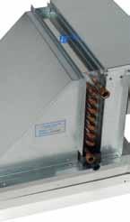
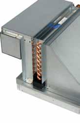


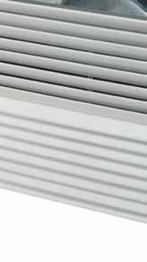
47 For the energy efficient buildings of today and tomorrow Chilled Beam/Induction Unit 1-Way Blow Chilled Beam Technical Specifications American Owned and Operated


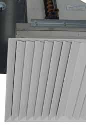
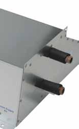
48 Chilled Beam/Induction Unit A Chilled Beam takes a source of primary air at a maximum inlet static pressure of 1 wc. It distributes this air through a bank of specially designed aerodynamic nozzles and discharges the air at a high velocity into a mixing chamber. This creates a differential pressure which enables a draw of room air across a coil. This imparts either sensible cooling or heating to the air as it passes over the coil. The primary air and induced air are mixed and discharged through a grille in a coanda effect air distribution at the ceiling. This air circulates throughout the room and is gently drawn back up through the return section of the Chilled Beam grille. Because the return air to the terminal is located at the ceiling and is moving so gently, dirt is not carried along with it and filters are not required to protect the coils. This eliminates the cost and labor required for this routine maintenance. Chilled Beams are extremely flexible and enhance the savings and effectiveness of primary air systems such as those using dedicated outside air. When using our Chilled Beams, the primary air system, which includes the dedicated outside air unit and the supply and exhaust ductwork, can be sized to handle only the required ventilation air. This reduces the size of the equipment and duct work making it easier to fit into a building space. This also reduces the energy required to supply the ventilation to the building. The total room air circulation is created solely by the induction principle within the terminal; therefore, there is no electric motor requiring an electric power source or maintenance for a fan and motor. As a result, the Chilled Beam is a very quiet and efficient way to provide comfort in a space. Model Q1 and Q1L 1-Way Blow Ceiling Mounted Induction Unit The Q1 and Q1L are ceiling mounted Chilled Beams that blow in one direction and are available in various configurations. They were primarily created for areas that require between 40 CFM to 100 CFM of ventilation air. The Q1 and Q1L units are available in 2- and 4-pipe configurations. The Q1 and Q1L are a perfect fit for office spaces, dormitory rooms, patient rooms, etc. They are also perfect for hallways and corridors and as a supplement to other Chilled Beam units. These units have drain pans and can be designed to handle both sensible and latent loads in the occupied space.
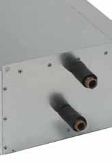
49 to UL 508 and UL 2043 No moving parts Prewired with 6-foot UL CMP cable LED indicator lights when switch cuts equipment Suitable for use in plenum spaces 24 volts AC class 2, 3 amp switching capacity Trap: Supplied in drainable drain pan application Bramec #0357 3/4 schedule 40 PVC R-trap 2 Filters: Cleanable woven aluminum Disposable Height Extension Collar: Available from 1 to 6 to facilitate gravity drainage from drain pan Must be added to overall height dimension shown on drawing 1/2" FNPT HWR 1/2" FNPT CWR " PRIMARY AIR CONNECTION 1/2" FNPT CWS /2" FNPT HWS /4" CPVC DRAIN SUPPLY AIR RETURN AIR The 4-Pipe unit shown above has left hand primary air and left hand chilled water piping connections. On 2-Pipe units the hot water supply and return are eliminated and the chilled water supply and return become common. Q1 and Q1L Installation and Balancing Instructions INSTALLATION 1. Packaging and installation for the Q1 and Q1L are identical. The following instructions are for both models. 2. Before opening the shipping carton that protects the Q1, please inspect the packaging for signs of physical damage. Damage should be noted on Shippers Bill of Lading and report same to the shipper and to NuClimate Air Quality Systems. Photographs of any damage will be helpful when making claims to the shipping company. 3. Open the carton top and cut the carton vertically on the where the duct collar is located. This unit has a 4 round duct collar for connection to the primary air ductwork. The 2-pipe unit has one 1/2 FPT chilled/hot water supply connection and one 1/2 FPT chilled/hot water return connection. 4-pipe units have four 1/2 FPT connections (CWS, HWS, CWR, HWR). The Chilled Water Supply (CWS) and Chilled Water Return (CWR) are on the same side as the duct collar. The Hot Water Supply (HWS) and Hot Water Return (HWR) are on the opposite side. 4. When supplied, the flexible hose connections and valves are shipped separately. It is important to connect the supply water to the supply water connections and return water to the return water connections. Note: The supply is connected to the bottom FPT connector and the return is connected to the top FPT connector. Be sure all air is vented from the coil before making final connections at the return. 5. The Q1 unit design allows for two condensate options. When not piping to a condensate drain, the unit will be supplied with a float switch shipped separately. The float switch should be wired to the room controller to shut off the coil valve if sufficient condensate should build up. If multiple units are used in a single zone, these switches should be wired in series to the room


50 For the energy efficient buildings of today and tomorrow Chilled Beam/Induction Unit 1-Way Blow Chilled Beam Technical Specifications American Owned and Operated


51 Chilled Beam/Induction Unit A Chilled Beam takes a source of primary air at a maximum inlet static pressure of 1 wc. It distributes this air through a bank of specially designed aerodynamic nozzles and discharges the air at a high velocity into a mixing chamber. This creates a differential pressure which enables a draw of room air across a coil. This imparts either sensible cooling or heating to the air as it passes over the coil. The primary air and induced air are mixed and discharged through a grille in a coanda effect air distribution at the ceiling. This air circulates throughout the room and is gently drawn back up through the return section of the Chilled Beam grille. Because the return air to the terminal is located at the ceiling and is moving so gently, dirt is not carried along with it and filters are not required to protect the coils. This eliminates the cost and labor required for this routine maintenance. Chilled Beams are extremely flexible and enhance the savings and effectiveness of primary air systems such as those using dedicated outside air. When using our Chilled Beams, the primary air system, which includes the dedicated outside air unit and the supply and exhaust ductwork, can be sized to handle only the required ventilation air. This reduces the size of the equipment and duct work making it easier to fit into a building space. This also reduces the energy required to supply the ventilation to the building. The total room air circulation is created solely by the induction principle within the terminal; therefore, there is no electric motor requiring an electric power source or maintenance for a fan and motor. As a result, the Chilled Beam is a very quiet and efficient way to provide comfort in a space. Model QLS 1-Way Blow Ceiling Mounted Induction Unit Model QLS units are 1-way blow, ceiling mounted Chilled Beams that are linear in dimension. The model QLS is 24 x 48 and is offered in 3 series: Series 24 is low capacity, Series 31 is medium capacity, and Series 38 is high capacity. These units have a 2-way grille which discharges on one side and returns on the other. They are available in various dimensions and configurations and can be custom designed for a specific job. They were primarily created for areas that require between 25 CFM and 200 CFM of ventilation air. QLS units are available in 2- and 4-pipe configurations. These units are a perfect fit for office spaces, dormitory rooms, labs, etc. They are also perfect as a supplement to other Chilled Beam units. These units have drain pans and can be designed to handle both sensible and latent loads in the occupied space.
52 3.54 Mounting: Bracket for use with wire hanging systems Special accomodations can be made to accommodate most hanging methods (contact the factory for further information) Float Switches: Standard Potted (electrically water sealed) reed/magnet switch design UL 508 Plenum rated Switch components and wire are tested to UL 508 and UL 2043 No moving parts Prewired with 6-foot UL CMP cable LED indicator lights when switch cuts equipment Suitable for use in plenum spaces 24 volts AC class 2, 3 amp switching capacity Trap: Supplied in drainable drain pan application Bramec #0357 3/4 schedule 40 PVC R-trap 2 Filters: Cleanable woven aluminum Disposable Height Extension Collar: Available from 1 to 6 to facilitate gravity drainage from drain pan Must be added to overall height dimension shown on drawing 1/2" FPT HWR /2" HANGING HOLES TYPICAL OF 4 1/2" FPT CWR 1/2" FPT CWS 3/4" CPVC DRAIN " 1/2" FPT HWS RETURN AIR SUPPLY AIR " PRIMARY AIR CONNECTION FRONT FACE The 4-Pipe unit shown above has front face primary air and left hand chilled water piping connections. On 2-Pipe units the hot water supply and return are eliminated and the chilled water supply and return become common. QLS Installation and Balancing Instructions INSTALLATION 1. Before opening the shipping carton that protects these units, please inspect the packaging for signs of physical damage. Damage should be noted on Shippers Bill of Lading and report same to the shipper and to NuClimate Air Quality Systems. Photographs of any damage will be helpful when making claims to the shipping company. 2. Open the carton top and fold the flaps back to gain access to the unit. Two people are required to lift the unit out of the carton. These units are shipped with the grilles attached and when setting it down, care must be taken to put it on a clean, soft surface so as to not scratch the grille face. The QLS has a 6 round duct collar for connection to the primary air ductwork. The 2-pipe units have one 1/2 FPT chilled/hot water supply and return connection on the same end as the 3/4 condensate drain connection. 4-pipe units have two 1/2 FPT connections (CWS and CWR) on the same end as the condensate connection. The two 1/2 FPT hot water connections (HWS and HWR) are on the opposite end of the unit from the chilled water. 3. When supplied, the flexible hose connections and valves are shipped separately. It is important to connect the supply water to the supply water connections and return water to the return water connections. Note: The supply is connected to the bottom FPT connector and the return is connected to the top FPT connector. Be sure all air is vented from the coil before making
53 Product Pumps GARCIA GALUSKA DESOUSA Consulting Engineers, Inc.
54


55 Bulletin B-207G Bell & Gossett Series 1510 Centrifugal Pumps Technical Bulletin For hydronic heating and cooling systems, industrial, pressure boosting and general pumping applications High efficiency, low operating costs Easy maintenance Seal options Part of the Bell & Gossett Equipment Selection Program


56 Take away these seven standard features and you ll have a pump like everyone else s. TRUE BACK PULLOUT A B&G standard in design and construction. Ease in service is assured, while piping and motor remain undisturbed. Extended delays for repairs are virtually eliminated. INTERNALLY SELF-FLUSHING MECHANICAL SEAL This design is way ahead of its time. This unique seal design is proven in many years of service. It requires no special external flushing provisions, since the design provides for constant efficient flushing action internally. This standard feature ensures maximum seal face lubrication, heat dissipation and debris removal without vulnerable, external flush tubing. The internal flushing action passes two and a half to three times the flow over the seal faces compared to a few GPM for conventional, stuffing-box designed pumps. SOLID-FOOT MOUNTED VOLUTE All Series 1510 pumps are provided as standard with an integrally cast volute foot located directly beneath the pump volute. This integrally cast foot ensures that the alignment between the volute and motor assembly is maintained. Without solid support beneath the volute, the piping weight alone will cause distortion which can lead to premature failure of the bearings, shaft and mechanical seal. This feature is equally important on hot water applications. The Series 1510 volute foot provides a solid foundation and eliminates the deflections which would otherwise exist within an unsupported overhung volute during the normal thermal expansion of the system piping against the volute. COMPUTER CONTROLLED IMPELLER BALANCING 1510 impellers are balanced to HI/ANSI section , balance grade G6.3 standards. This method of computer balancing Impellers provides for quiet, efficient, vibration free performance. Diameters are computer selected at the factory to furnish assurance that your capacity requirements will be met. CENTER DROP-OUT SPACER COUPLING Unlike conventional jaw type or rigid style couplings, a center drop-out spacer coupling allows removal of the bearing frame and rotating element without disturbing the pump end pipe alignment or motor electrical connections. HEAVY DUTY, RUGGED BASEPLATE The Bell & Gossett fabricated heavy duty baseplate is supplied as standard on every Series 1510 pump. Unlike rolled steel and C channel baseplates, the Series 1510 baseplate provides a heavy duty saddle assembly, full seam welds, closed baseplate ends and an open top to provide ease of access for proper equipment grouting. ANSI/OSHA-COMPLIANT COUPLING GUARD The coupler guard complies with ANSI B15.1, Section 8 and OSHA The guard offers increased protection against potential injuries and is standard on all 1510 pumps. The guards include slotted viewing windows for easy inspection. 3
 Slinger Slinger 4 Shaft Sleeve 5 Impeller Key 6 Impeller Washer 7 Impeller Lock Washer")
 (OPTIONAL) (OPTIONAL) 11 Shaft Steel SAE 1144 Steel SAE 1144 Steel SAE 1144 12 Volute Cast Iron Cast Iron Cast Bronze ASTM #A159 ASTM #A159")
57 Materials of Construction 1 Gauge Tapping 9 Volute Gasket 10 Seal Assembly Shaft Vent Plug 2 Volute 3 Impeller Gauge Tapping Bronze Casing Wearing Ring (Optional) 1 Packing Packing Gland Shaft 9 Volute Gasket 2 Volute Gauge Tapping Lantern Ring 3 Impeller Gauge Tapping Bronze Casing Wearing Ring (Optional) Slinger Slinger 4 Shaft Sleeve 5 Impeller Key 6 Impeller Washer 7 Impeller Lock Washer Impeller Cap Screw 4 Shaft Sleeve 5 Impeller Key 6 Impeller Washer 7 Impeller Lock Washer Impeller Cap Screw Drain Plug Standard Configuration Optional S Configuration BRONZE FITTED ALL IRON ALL BRONZE PUMP (STANDARD PUMP PUMP* DESCRIPTION CONFIGURATION) (OPTIONAL) (OPTIONAL) 11 Shaft Steel SAE 1144 Steel SAE 1144 Steel SAE Volute Cast Iron Cast Iron Cast Bronze ASTM #A159 ASTM #A159 ASTM #B Impeller Cast Bronze Cast Iron Cast Bronze ASTM #B584 ASTM #A159 ASTM #B Shaft Sleeve Aluminum Bronze #304 Stainless Steel Aluminum Bronze ASTM #B111 ASTM #A312 ASTM #B Impeller Key #304 Stainless Steel #304 Stainless Steel #304 Stainless Steel 16 Impeller Washer 1510 Steel Stainless Steel Brass 17 Impeller Lock Washer #304 Stainless Steel #304 Stainless Steel #304 Stainless Steel 18 Impeller Cap Screw #304 Stainless Steel #304 Stainless Steel #304 Stainless Steel 19 Volute Gasket Cellulose Fiber Cellulose Fiber Cellulose Fiber 10 Seal Assemblies Standard Seal Bellows Buna N Buna N Buna N Faces Carbon-Ceramic Carbon-Ceramic Carbon-Ceramic Metal Parts Brass Stainless Steel Brass Spring Stainless Steel Stainless Steel Stainless Steel For Stuffing Box 10A Flushed Single O-Rings EPR EPR Faces Carbon-Tungsten Carbon-Tungsten Carbide Carbide Metal Parts Stainless Steel Stainless Steel Spring Stainless Steel Stainless Steel Packed Packing Graphited Graphited Impregnated Teflon Impregnated Teflon Gland Bronze Cast Iron Lantern Ring Filled TFE Filled TFE * All Bronze Construction NOT available in following sizes: 1 1 /2AC, 3AC, 3BC, 4AC, 5A, 4BC, 5BC, 6BC, all E, and all G sizes, or stuffing box configuration. ** For operating temperatures above 250 F, a cooled flush is required and is recommended for temperatures above 225 F for optimum seal life. On closed systems, cooling is accomplished by inserting a small heat exchanger in the flush line to cool the fluid. Flush-line Filters and Sediment Separators are available on special request. OPTIONAL FEATURES All Iron Construction All Bronze Construction* Bronze Casing Wear Ring Stainless Steel Shaft Sleeve Stainless Steel Shaft Drip Pan EPT/Tungsten Carbide Seal (Standard Configuration only) Stuffing Box Construction with several seal and packing options SEAL SELECTION GUIDE FOR: A. STANDARD SEALS BUNA-PH Limitations 7-9; Temperature Range 20 F to +225 F EPT-PH Limitations 7-11; Temperature Range 20 F to +250 F For use on open or closed clear water systems. Maximum working pressure 175 psi. B. FLUSHED SINGLE SEALS (Stuffing Box Design) PH Limitations 7-11; Temperature Range 20 F to +300 F** For use on closed or open systems where the temperature or pressure requirements exceed the limitations of the standard seal. Available in 175 psi, or 250 psi working pressures. C. FLUSHED DOUBLE SEALS (Stuffing Box Design) PH Limitations 7-9; Temperature Range 0 F to +250 F For use on closed or open low pressure systems which may contain a high concentration of abrasives. An external flush is required. Maximum working pressure 175 psi. D. PACKING (Stuffing Box Design) PH Limitations 7-9; Temperature Range 0 F to +190 F For use on open or closed systems which require a large amount of make-up water, as well as systems which are subjected to widely varying chemical conditions and solids buildup. 5
58
59 Product VAV Boxes GARCIA GALUSKA DESOUSA Consulting Engineers, Inc.
60
, SDV (digital controls) SEV (electronic controls) single duct VAV assemblies.")
61 Single Duct Terminal Units SPV, SEV, SDV Series Single Duct Controller Type Product Overview TERMINAL UNITS General Information Price has, as a primary component of its terminal unit line, the SPV (pneumatic controls), SDV (digital controls) SEV (electronic controls) single duct VAV assemblies. These units are designed to control the airflow rate of conditioned air into an occupied space in response to a control signal, usually a thermostat. The clean and efficient design of these single duct terminal units result in a system component which has minimal pressure drop reducing fan horsepower requirements, and low noise generation for quiet operation. A compact configuration makes this unit easier to use in today s crowded mechanical spaces or in retrofitting existing systems. Control options for this product line are wide and varied with pneumatic, analog electronic and state of the art direct digital control available to suit most any application. Most of the control options utilize the exclusive Price SP300 multipoint sensor for accurate duct air velocity pressure measure ment. This allows the terminals to monitor the desired flow rate, as dictated by the thermostat, and com pensate instantly for any changes in supply air pressure that might tend to alter the supply volume. In other words, the net result is a pressure indepen dent variable air volume system. In addition to the basic volume control assembly, a complete line of accessories is offered to meet specific job requirements. Sound attenuators, multi-outlet adaptors and heating coils are all available. These are factory assembled to the basic assembly for ship ment as an integrated unit (see page F34). Features: Capacities ranging from cfm in 11 sizes. Pressure independent operation. Can be used for VAV or constant volume applications. Available with pneumatic, electronic or direct digital controls. Factory calibrated to job requirements. Individually adjustable minimum and maximum air volumes easily field adjusted. SP300 multi-point flow sensor designed to maintain control accuracy independent of field installation conditions. Gauge taps for flow measurement and balancing. Conveniently accessible externally mounted controls. Inlet connection bead offers a means for secure flex duct connections. A full 2" inlet connection to secure flex and hard duct connections. Full range of accessories available (i.e. coils, attenuators, etc.) F-10 Model SEV Product Selection Checklist 1] Select Unit Inlet Size based on control and acoustic parameters. 2] Select Control type (Pneumatic, Electronic, Digital) based on system design. 3] Select Accessories (Multi-Outlet Adaptor, Attenuator) as required. 4] Select Reheat Coil, if required. 5] Select Control Sequence based on system design. NEMA1 Protective metal shrouds for elec tronic and digital (by Price) controls. Protective metal cover optional for pneumatic controls. Compact, lightweight design for ease of installation. 22 gauge zinc-coated steel housing (optional 20 gauge available). 1 /2" (13) thick, min. 1.5 lb density fiberglass internal insulation, coated to prevent air erosion meets requirements for NFPA90A and UL /4" (19) and 1" (25) insulation also available as an option. Damper blade constructed of two layers of heavy gauge galvanized steel with a sandwiched peripheral gasket of cross linked polyurethane foam to ensure tight seal and no damper deflection. Plated damper shaft is mounted in selflubricating bearings. Discharge complete with slip and drive cleat duct connections. Special liners and insulations available see pages F39-F42. Certified in accordance with the ARI 880 certification program. Electronic & DDC units are CSA certified. Product Information Index Dimensional Data... F11-F12 Accessories...F13-F14 Control Options...F81 SP300 Sensor...F15-F17 Air Volume Ranges... F18 Selection Guide... F19-F21 Acoustical Data...F22-F25 Coil Selection...F83 Electric Coils...F90-F95 Liners...F39-F42 Low Leakage... F13 Suggested Specification...F347 All Metric dimensions ( ) are soft conversion. Copyright E.H. Price Limited Imperial dimensions are converted to metric and rounded to the nearest millimetre.
62
63 Product Unit Heaters GARCIA GALUSKA DESOUSA Consulting Engineers, Inc.
64

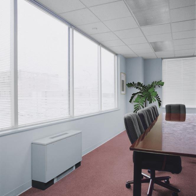
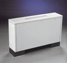
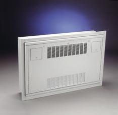
65 HYDRO-AIR COMPONENTS INC. HYDRONIC CABINET UNIT HEATERS
66 Cabinet Unit Heater Models and Airflow Arrangements MODEL ARRANGEMENT NUMBER FLOOR (RF) RF-200 RF % FRESH AIR RF-220 RF % FRESH AIR FLOOR INVERTED FLOW (RFI) RFI-240 RFI-250 WALL (RW) RW-260 RW-270 RW-280 WALL INVERTED FLOW (RWI) RWI-290 RWI-300 RWI-310 PARTIALLY RECESSED WALL (RRW) PARTIALLY RECESSED WALL INVERTED FLOW (RRWI) FULLY RECESSED WALL (RFRW) FULLY RECESSED WALL INVERTED FLOW (RFRWI) RRW-320 RFRW-340 RRWI-330 RFRWI-350 CEILING (RC) RC-360 RC-370 RC-380 RC-390 RC-400 FULLY RECESSED CEILING (RFRC) RFRC-410 RFRC-420 RFRC-430 PARTIALLY RECESSED CEILING (RRC) RRC-440 2
 RFI-FLOOR, INVERTED")
 RFRW - FULLY RECESSED WALL 1 Arrangement")
 RWI - WALL, INVERTED FLOW 3 Arrangements (RWI-290 shown) RFRWI -")
")
 RRC-PARTIALLY RECESSED CEILING 1")
67 Cabinet Unit Heater Models 11 Models in 25 Arrangements to Meet Your Specifications RF-FLOOR 4 Arrangements (RF-200 shown) RFI-FLOOR, INVERTED FLOW 2 Arrangements (RFI-240 shown with optional return grille) RW-WALL 3 Arrangements (RW-260 shown) RFRW - FULLY RECESSED WALL 1 Arrangement (RFRW- 340 shown) RRW-PARTIALLY RECESSED WALL 1 Arrangement (RRW- 320 shown) RWI - WALL, INVERTED FLOW 3 Arrangements (RWI-290 shown) RFRWI - FULLY RECESSED WALL, INVERTED FLOW 1 Arrangement (RFRWI-350 shown) RRWI - PARTIALLY RECESSED WALL, INVERTED FLOW 1 Arrangement (RRWI-330 shown) RC-CEILING 5 Arrangements (RC-360 shown) RFRC- FULLY RECESSED CEILING 3 Arrangements (RFRC-420 shown) RRC-PARTIALLY RECESSED CEILING 1 Arrangement (RRC-440 shown) 3
68 Dimensions and Data MODEL RF & RFI LH PIPING CONNECTIONS SHOWN AS STANDARD, RH OPPOSITE. PIPING HAND DETERMINED WHEN FACING AIR OUTLET. ELECTRICAL OPPOSITE PIPING. See for any recent updates or changes 23
69 Dimensions and Data MODEL RRW & RRWI & RFRW & RFRWI & RRC & RFRC LH PIPING CONNECTIONS SHOWN AS STANDARD, RH OPPOSITE. PIPING HAND DETERMINED WHEN FACING AIR OUTLET. ELECTRICAL OPPOSITE PIPING. 26 See for any recent updates or changes


70 HYDRO-AIR COMPONENTS INC. HYDRO-AIR COMPONENTS INC. UNIT HEATERS FOR STEAM OR HOT WATER
71 RH Dimensional Data B E RH-18 through RH-86 3/8-16 mounting taps G F NPT Pipe Connection A H C D B E RH-108 through RH-340 3/8-16 mounting taps G F NPT Pipe Connection A Table 20-1 MODEL RH DIMENSIONS* MODEL A B C D E F G H J RH-18 RH-24 RH-33 RH-47 RH-63 RH-86 RH-108 RH-121 RH-165 RH-193 RH-258 RH-290 RH /8 16 7/8 19 3/4 19 3/4 25 3/4 25 3/4 25 7/8 25 7/8 31 7/8 31 7/ / / /16 7 1/2 7 1/2 7 1/2 7 1/2 8 1/2 8 1/2 9 1/2 9 1/ /2 4 1/2 4 3/4 4 3/4 4 3/4 4 3/4 6 1/4 6 1/4 6 1/4 8 3/8 8 3/8 8 3/8 8 3/ /8 24 7/8 32 7/8 32 7/8 32 7/8 J 3 1/2 3 1/2 3 1/2 3 1/2 3 1/2 3 1/2 3 1/2 3 1/2 3 1/2 3 1/2 3 1/2 3 1/2 3 1/ /4 5 1/4 6 1/4 6 1/4 6 1/4 6 1/4 7 1/ C /4 2 1/4 2 1/4 D NPT CONNECTIONS 3/4 3/4 3/4 3/4 3/4 3/4 1 1/2 1 1/2 1 1/2 1 1/ FAN DIAMETER APPROX. SHIPPING WT. LB * All dimensions in inches. ** RH-18 through RH-86 have side female NPT pipe connections. RH-108 through RH-340 have top and bottom male NPT pipe connections. *** Units should be mounted a minimum of 5" from wall.
72
73 Product Ductless Cooling Units GARCIA GALUSKA DESOUSA Consulting Engineers, Inc.
74


75 PKFY OVERVIEW (wall mounted) Elegant design and compact dimensions ideal for offices, classrooms, and residential uses. PKFY-P-NAMU-E PKFY-P-NGMU-E PKFY-P-NFMU-E Capacity range: 6,000 to 30,000 Btu/h A wide selection for your design and performance needs Whatever the size or shape of your room, there is a Mitsubishi Electric PKFY unit that is just right, delivering the style and performance you demand and deserve. PKFY units mount high on the wall and blend in beautifully into any space. They are compact and lightweight. In addition, they are extremely quiet with one of the lowest sound ratings available. When it comes to comfort, the PKFY auto-vane feature delivers optimal air distribution and uniform temperatures throughout your space. All of this performance and design flexibility comes in a unit that is remarkably easy to install and maintain. The template and back mounting plate shipped with each unit make installation a snap. Front grille opens for easy filter cleaning The front grille hinges open easily with no tools needed to gain quick access to the filter. The filter can be removed and cleaned as needed. Front grille opens for filter access Operation is among the quietest available The unit incorporates a random-pitch fan to assure quiet operation. The optimal design of the airflow passage features a small fan diameter to allow for a compact installation. Thanks to practical casing configuration, airflow generated by the fan is distributed uniformly. This design also suppresses condensation. Swing vane User selectable vane swing setting with PAR-21MAA and PAR-F27MEA controllers enhances air distribution in the conditioned space. Five-way piping provides flexibility in selecting installation sites Refrigerant and drain piping can be connected from the rear, right, base, and left of the unit, providing much greater flexibility for piping and selecting an installation site. 30
76 PKFY-P-N*MU-E SPECIFICATIONS PKFY-P-NAMU-E PKFY-P-NGMU-E PKFY-P-NFMU-E Model Name PKFY-P06NAMU-E PKFY-P08NAMU-E PKFY-P12NGMU-E PKFY-P15NGMU-E Power Source 208/230V, 1 Phase, 60Hz Cooling Capacity Btu/h *1 6,000 8,000 12,000 15,000 Heating Capacity Btu/h *1 6,700 9,000 13,500 17,000 Power Consumption Cooling W Heating W Current Cooling A Heating A External Finish (Munsell No.) 2.60Y 8.66/ Y 8.66/ Y 8.59/ Y 8.59/0.97 Dimensions Height Inches 11-5/8 11-5/ / /32 Width Inches 32-3/ / Depth Inches 6-1/4 6-1/4 9-9/32 9-9/32 Net Weight Unit Pounds Heat Exchanger Cross Fin (Aluminum Plate Fin and Copper Tube) Fan Type x quantity Line Flow Fan x 1 Airflow Rate *2 CFM Motor Type Single Phase Induction Motor Motor Output W Air Filter Washable Filter Refrigerant Pipe Low Pressure (Flare) Inches 1/2 1/2 1/2 1/2 Dimensions High Pressure (Flare) Inches 1/4 1/4 1/4 1/4 Drain Pipe Dimension Inches I.D. 5/8 I.D. 5/8 I.D. 13/16 I.D. 13/16 Sound Levels *2 Low-Mid1-Mid2-High db(a) Model Name PKFY-P18NFMU-E PKFY-P24NFMU-E PKFY-P30NFMU-E Power Source 208/230V, 1 Phase, 60Hz Cooling Capacity Btu/h *1 18,000 24,000 30,000 Heating Capacity Btu/h *1 20,000 27,000 34,000 Power Consumption Cooling W Heating W Current Cooling A Heating A External Finish (Munsell No.) 3.4Y 7.7/ Y 7.7/ Y 7.7/0.8 Dimensions Height Inches 13-13/ / /32 Width Inches 55-1/8 55-1/8 66-5/32 Depth Inches 9-9/32 9-9/32 9-9/32 Net Weight Unit Pounds Heat Exchanger Cross Fin (Aluminum Plate Fin and Copper Tube) Fan Type x quantity Line Flow Fan x 2 Airflow Rate *2 CFM Motor Type Single Phase Induction Motor Motor Output W Air Filter Washable Filter Refrigerant Pipe Low Pressure (Flare) Inches 1/2 5/8 5/8 Dimensions High Pressure (Flare) Inches 1/4 3/8 3/8 Drain Pipe Dimension Inches I.D. 13/16 I.D. 13/16 I.D. 13/16 Sound Levels *2 Low-High db(a) INDOOR UNITS Note: *1 Cooling / Heating capacity indicates the maximum value at operation under the following conditions: Cooling: Indoor: 80 F (27 C) DB / 67 F (19 C) WB; Outdoor: 95 F (35 C) DB Heating: Indoor: 70 F (21 C) DB; Outdoor: 45 F (7 C) DB / 43 F (6 C) WB *2 Airflow rate / sound levels are at (Low-Mid1-Mid2-High) or (Low-High) Ventilation Air: Providing sufficient ventilation air is an important part of every building design. ASHRAE standard 62 provides the minimum air requirements. Also check local codes. 31


77 PLFY OVERVIEW (ceiling-recessed) Perfect airflow to meet your needs with four-way control. PLFY-NBMU Ceiling applications The PLFY-NBMU has a unit height of only 10-1/4 or 11-3/4, depending on the model, and provides great looking installations in low-ceiling areas with very limited space /4 or 11 3 /4 Capacity range: 12,000 36,000 Btu/h PLFY-NCMU PLFY-Series indoor units offer unequaled flexibility of installation. Their compact ceiling-recessed design makes them easy to install and operate. Their exceptional performance provides excellent air coverage. Two styles are available. High performance and versatility The PLFY looks great and works beautifully. The four-way cassette-type unit is compact and recesses easily into a ceiling space so all you see is an attractive, flush-mounted grille. Beneath that elegant exterior is a powerful, high-performance machine with a built-in drain lift-up mechanism. The fan is engineered to provide optimum air distribution with minimal sound. Both styles can bring in outside air into your space, the PLFY- NBMU can also branch over to air condition an adjacent room. The PLFY-NCMU unit is specifically designed to fit within a ceiling grid for ease of installation. 32 PLFY-P-NBMU 37-7 /16 PLFY-P-NCMU 25-5 /8 Quiet operation These powerful indoor units are whisper-quiet, down to 29 db(a) for the PLFY-NCMU and 27 db(a) for the PLFY-NBMU. At only 8-3/16 in height and only 22-7/16 x 22/7/16 in width, the PLFY- NCMU makes accessing even the tightest of ceiling installations a possibility. The NCMU s grille is color-matched with the NBMU and blends in well with white drop ceiling tiles. Customize the airflow pattern to meet your needs The different airflow patterns provide the best solution for a variety of room layouts and airconditioning requirements. For extra versatility, you can select from two-, three-, or four-way airflow. Built-in condensate lift mechanism The drain piping of the PLFY-NBMU can be positioned anywhere up to 33-1/2 inches from the ceiling s surface, allowing for long piping and versatility. A built-in switch halts operation if an error with the pump occurs, ensuring that no water leaks from the unit. PLFY-NBMU The PLFY-NCMU model has a built-in pump that lifts condensation 20 inches from the ceiling s surface. The unit recognizes when there is a pump failure and safeguards against leaks.


 In the Heating mode on the PLFY-NBMU, each air outlet vane operates independently, distributing warm air in multiple directions for better room heating.")
78 Corner-pocket design simplifies maintenance and installation PLFY-NBMU allows access through the pockets equipped on all four corners of the grille to complete installation, maintenance work, and height adjustment. Easy maintenance, long-life filter The washable filter provides about 2,500 hours of use in a normal office environment before cleaning is needed. The PLFY-NBMU is also available with an optional multi-function casement that allows for additional ventilation air and better filtration. ADDITIONAL FEATURES FOR PLFY-NBMU MODELS Wider air stream Longer air outlets on the PLFY-NBMU unit deliver wider air streams for improved air distribution and energy savings. This feature means quieter air delivery with fewer drafts and great overall cooling and heating coverage. Previous Model Air outlet hole: 16-3/16 In. PLFY-NBMU-E Air outlet hole: 19-11/16 In. Auto Wave airflow feature (Heating Mode) In the Heating mode on the PLFY-NBMU, each air outlet vane operates independently, distributing warm air in multiple directions for better room heating. Independent vane motor control Each of the four vanes on the PLFY-NBMU can be set by the wired remote controller to operate independently to match the room layout. Specific vane settings include five fixed directions plus swing. Auto fan speed feature The PLFY-NBMU unit offers the choice from four set fan speeds, or auto fan speed, to ensure faster achievement of room temperature target. Auto fan speed mode allows the fan to adjust its speed based on the degree of differential between set point and room temperature. The i-see sensor accessory In addition to the return air temperature, the PLFY-NBMU four-way ceiling cassette with the field installed i-see sensor measures the floor temperature in real time, observing the room vertically for better management of sensible temperature (temperature felt by occupant). The i-see sensor measures the infrared rays generated from the surrounding wall and floor surface at an angle of 360. The infrared ray energy is converted into a temperature value. The i-see sensor rotates 90 slowly in five-second intervals for correct measurement of temperature to cover the full floor space. INDOOR UNITS Low Mid1 Mid2 High Auto 33

79 PLFY-P-NBMU-E SPECIFICATIONS 34
COHASSET, MA March 6, The following is the HVAC outline specifications, which defines the scope of work of the HVAC system.
 23 00 00 HEATING, VENTILATING & AIR-CONDITIONING The following is the HVAC outline specifications, which defines the scope of work of the HVAC system. PART 1 GENERAL 1.1 CODES A. All work installed under
GARCIA GALUSKA DESOUSA Consulting Engineers
 L#57295/Page 1/July 21, 2017 HVAC SYSTEMS NARRATIVE REPORT The following is the HVAC system narrative, which defines the scope of work and capacities of the HVAC system as well as the Basis of Design.
SECTION HVAC TABLE OF CONTENTS PART 1 - SYSTEM DESCRIPTION / OUTLINE SPECIFICATIONS FILED SUB BID PROJECT OVERVIEW...
 SECTION 230001 TABLE OF CONTENTS SECTION 230001 PART 1 - SYSTEM DESCRIPTION / OUTLINE SPECIFICATIONS... 1 1.00 FILED SUB BID... 1 1.01 PROJECT OVERVIEW... 2 1.02 DESIGN CRITERIA... 4 1.03 CODE ISSUES...
GARCIA GALUSKA DESOUSA Consulting Engineers
 L#56566/Page 1/May 23, 2017 HVAC Heating Plant The original Town Hall building and Addition building are primarily heated by a gas fired hot water plant that is located in the basement. The boiler plant
SECTION PACKAGED, OUTDOOR, CENTRAL-STATION AIR-HANDLING UNITS
 SECTION 237413 - PACKAGED, OUTDOOR, CENTRAL-STATION AIR-HANDLING UNITS PART 1 - GENERAL 1.1 SUMMARY A. This Section includes packaged, outdoor, central-station air-handling units (rooftop units) with the
A. Base Bid: 1. Heating Contractor provide: a. Control sequences for HVAC systems, subsystems, and equipment.
 SECTION 23 09 93 - SEQUENCE OF OPERATIONS FOR HVAC CONTROLS PART 1 - GENERAL 1 WORK INCLUDES A. Base Bid: Heating Contractor provide: Control sequences for HVAC systems, subsystems, and equipment. B. Alternate
BOOK 1 OVERVIEW RD2XRT INSTALLATION AND OPERATION MANUAL. Table of Contents ABOUT BOOK 1:
 4510 Helgesen Drive, Madison, WI, 53718 608.221.4499, 800.627.4499, Fax: 608.221.2824 support@renewaire.com www.renewaire.com RD2XRT INSTALLATION AND OPERATION MANUAL BOOK 1 OVERVIEW ABOUT BOOK 1: This
HVAC 101. H V A C S y s t e m s
 H V A C 1 0 1 S y s t e m s Introduction & Overview Should you care? Mechanical System Types Components & operation Popular Application Key Issues and Design Considerations System Comparisons First Cost
PINNACLE SERIES DEDICATED OUTDOOR AIR SYSTEM ENERGY EFFICIENT DEHUMIDIFICATION
 ENERGY EFFICIENT DEHUMIDIFICATION PINNACLE SERIES DEDICATED OUTDOOR AIR SYSTEM Provides a very high degree of latent cooling using only a minimal amount of conventional cooling input Substantial energy
Energy-Efficient Makeup Air Units BY HUGH CROWTHER, P.ENG., MEMBER ASHRAE
 This article was published in ASHRAE Journal, March 20145 Copyright 2015 ASHRAE. Posted at www.ashrae.org. This article may not be copied and/or distributed electronically or in paper form without permission
AIR-CONDITIONING SYSTEMS AND APPLICATIONS. Abdullah Nuhait Ph D. King Saud University
 AIR-CONDITIONING SYSTEMS AND APPLICATIONS Abdullah Nuhait Ph D. King Saud University AIR-CONDITIONING SYSTEMS Earliest air conditioning system used only for heating (winter) Provided heated air for comfort
RoofPak Applied Rooftop Systems
 RoofPak Applied Rooftop Systems RoofPak Applied Rooftop Systems Design flexibility, energy efficiency, system performance and reliability make Daikin RoofPak applied rooftop systems the ideal solution
CHAPTER 4. HVAC DELIVERY SYSTEMS
 CHAPTER 4. HVAC DELIVERY SYSTEMS 4.1 Introduction 4.2 Centralized System versus Individual System 4.3 Heat Transfer Fluids 4.4 CAV versus VAV Systems 4.5 Common Systems for Heating and Cooling 4.6 Economizer
DIVISION 15 MECHANICAL
 DIVISION 15 MECHANICAL A. GENERAL DESIGN CONDITIONS 1. Design occupied spaces to maintain 72 F and a space dew point temperature not to exceed 55 F. 2. Design classroom and office space buildings with
BOOK 1 OVERVIEW RD2XIN INSTALLATION AND OPERATION MANUAL. Table of Contents ABOUT BOOK 1:
 4510 Helgesen Drive, Madison, WI, 53718 608.221.4499, 800.627.4499, Fax: 608.221.2824 support@renewaire.com www.renewaire.com RD2XIN INSTALLATION AND OPERATION MANUAL BOOK 1 OVERVIEW ABOUT BOOK 1: This
ENGINEERING BULLETIN. Overview of Chilled Beam Technology. Purpose. Summary. Theory
 Overview of Chilled Beam Technology Purpose Chilled beam technology is new to the United States but has been used in Europe since the 1950 s. Chilled beams can reduce energy costs, improve indoor air quality,
System Components with ` Emphasis on Packaged Rooftop Application and Installation. Jerry Cohen President Jacco & Assoc.
 System Components with ` Emphasis on Packaged Rooftop Application and Installation Jerry Cohen President Jacco & Assoc. Agenda Define and relate in practical terms the following components: System Effect
A. Product Data: Include rated capacities, operating characteristics, furnished specialties, and accessories.
 Page 238219-1 SECTION 238219 - PART 1 - GENERAL 1.1 RELATED DOCUMENTS A. Drawings and general provisions of the Contract, including General and Supplementary Conditions and Division 01 Specification Sections,
Evaluation. ems. Prepared By: Martha. a s Vineyard. Box P.O. Box June 2015
 Martha a s Vineyard Regional High School Vineyard Haven, MA 2 2015 HVAC Syste ems Evaluation Prepared For: Martha s Vineyard Regional School District Box 1385 Oaks Bluff, MA 02557 Prepared By: BLW Engineers,
Modular Supply Make-Up Air Unit
 Modular Supply Make-Up Air Unit Model MSX Flexible Design Factory Assembled Heating Options Hot Water Steam Electric Cooling Options Evaporative Direct Expansion Chilled Water November 2009 Product Features
Topic 2. ME 414/514 HVAC Systems Overview Topic 2. Equipment. Outline
 ME 414/514 HVAC Systems Overview Equipment Outline 2-1 The Complete System 2-2 The Air-Conditioning and Distribution System 2-3 Mechanical Equipment Air-handling Equipment Heating Equipment Boilers Furnaces
PACKAGED ROOFTOP UNITS, AIR-SOURCE HEAT PUMPS, WATER-SOURCE / GEOTHERMAL HEAT PUMPS, & OUTDOOR AIR HANDLING UNTS. RQ Series.
 RN/RQ Series PACKAGED ROOFTOP UNITS, AIR-SOURCE HEAT PUMPS, WATER-SOURCE / GEOTHERMAL HEAT PUMPS, & OUTDOOR AIR HANDLING UNTS RQ Series Features: Air-cooled or water-cooled condenser, with unit capacities
FAST AND ROBUST BUILDING SIMULATION SOFTWARE. Chilled Beam Performance: 1 Shelly Street, Sydney
 FAST AND ROBUST BUILDING SIMULATION SOFTWARE Chilled Beam Performance: 1 Shelly Street, Sydney 3D Model Creation 1 Shelley Street, Sydney 3D Model Creation 1 Shelley Street, Sydney Daylight Analysis 1
The ultimate fresh air solution.
 Fresh Access The ultimate fresh air solution. Introducing Fresh Access TM. Expertly designed, our innovative energy recovery ventilator (ERV) unit, split dedicated outside air system (DOAS), and packaged
SECTION AIR COILS
 PART 1 - GENERAL 1.1 RELATED DOCUMENTS A. Drawings and general provisions of the Contract, including General and Supplementary Conditions and Specification Sections, apply to this Section. B. Related Sections:
KINGS COUNTY JAIL EXPANSION PHASE III COUNTY OF KINGS SECTION
 SECTION 237433, PART 1 - GENERAL 1.1 RELATED DOCUMENTS A. Drawings and general provisions of the Contract, including General and Supplementary Conditions and Division 01 Specification Sections, apply to
The Creative and Performing Arts High School (CAPA) Pittsburgh, PA 11/11/2002 Andrew Tech Mechanical Option Prof. S. A. Mumma
 Pittsburgh, PA 11/11/2002 Andrew Tech Mechanical Option Prof. S. A. Mumma") Objectives and Requirements For the Creative and Performing Arts High School (CAPA), the main objective of the mechanical design is to provide an energy efficient system that is easily maintainable and
Objectives and Requirements For the Creative and Performing Arts High School (CAPA), the main objective of the mechanical design is to provide an energy efficient system that is easily maintainable and
RN/RQ. Series PACKAGED ROOFTOP UNITS, AIR-SOURCE HEAT PUMPS, WATER-SOURCE/ GEOTHERMAL HEAT PUMPS, & OUTDOOR AIR HANDLING UNITS.
 RN/RQ Series PACKAGED ROOFTOP UNITS, AIR-SOURCE HEAT PUMPS, WATER-SOURCE/ GEOTHERMAL HEAT PUMPS, & OUTDOOR AIR HANDLING UNITS RQ Series Features: Air-cooled or water-cooled condenser, with unit capacities
Heat Pumps SB SERIES. Vertical Self-Contained Unit Water-Source Heat Pumps (3-18 tons) Features:
 Features:") Heat Pumps SB SERIES SB Series Vertical Self-Contained Unit Water-Source Heat Pumps (3-18 tons) Features: Vertical self-contained units with capacities from 3-18 tons ECM driven direct drive backward curved
Heat Pumps SB SERIES SB Series Vertical Self-Contained Unit Water-Source Heat Pumps (3-18 tons) Features: Vertical self-contained units with capacities from 3-18 tons ECM driven direct drive backward curved
H3/V3 Series Horizontal and Vertical Indoor Air Handling Units. Engineering Catalog
 H3/V3 Series Horizontal and Vertical Indoor Air Handling Units Engineering Catalog Table of Contents AAON H3/V3 Series Features and Options Introduction... 6 H3/V3 Base Model Description... 7 Unit Size...
State of the art building simulation software... Frenger Radiant chilled beam performance at 1 Shelly St - Sydney
 Frenger Radiant chilled beam performance at 3D Model Creation Daylight Analysis Comparison of the performance of various HVAC systems at 1 Shelly St, Sydney VAV fancoil Active chilled beam Passive chilled
Job Name Control Systems Description Date
 Job Name Control Systems Description Date Project Overview The project is a describe the building and its major HVAC systems (e.g. three-story office building, served by a rooftop unit VAV system ). In
Energy Recovery with Cooling and Heating
 Energy Recovery with Cooling and Heating VersiVent - Model VER Commercial Institutional 2,000-10,000 cfm 3.0 in. wg external static pressure Configurable September 2008 Page The VersiVent Header Model
Dehumidifying with Dedicated Outdoor Air
 Dehumidifying with Dedicated Outdoor Air System Configurations Figure 71. Configurations for dedicated outdoor-air systems A dedicated outdoor-air handler separately filters, cools, dehumidifies, heats,
Energy Management and Controls
 As with the Chapter Review Tests and the Final Exam, the tests your understanding of the materials underlying the learning objectives. After you ve reviewed your answers to the Chapter Review Tests, try
Brown University Revised August 3, 2012 Facilities Design & Construction Standards SECTION AIR HANDLING UNITS
 SECTION 23 70 00 AIR HANDLING UNITS PART 1. GENERAL 1.1 Section includes air-handling units to 15,000 cfm and accessories. 1.2 Related Sections 1 : A. Division 01 - Brown University Standard for Narragansett
UNIVERSITY OF MISSOURI Heating Ventilating and Air-Conditioning (HVAC) 2016 Q1
 2016 Q1") GENERAL: This section provides general standards for overall sizing and design of Heating, Ventilating, and Air Conditioning (HVAC) systems. Other sections contain specific standards for each system per
GENERAL: This section provides general standards for overall sizing and design of Heating, Ventilating, and Air Conditioning (HVAC) systems. Other sections contain specific standards for each system per
SECTION PACKAGED ROOFTOP AIR CONDITIONING UNITS
 SECTION 15732 - PACKAGED ROOFTOP AIR CONDITIONING UNITS PART 1 - GENERAL 1.1 SECTION INCLUDES A. Package roof top unit. B. Heat exchanger. C. Refrigeration components. D. Unit operating controls. E. Roof
SECTION SPLIT-SYSTEM AIR-CONDITIONERS
 SECTION 238126 PART 1 - GENERAL 1.1 RELATED DOCUMENTS A. Drawings and general provisions of the Contract, including General and Supplementary Conditions and Division 01 Specification Sections, apply to
EADQUARTERS. Technical Report One. Stephanie Kunkel Mechanical Option
 EADQUARTERS 707 N. Calvert St. Technical Report One ASHRAE Standard 62.1 Ventilation ASHRAE Standard 90.1 Energy Design Stephanie Kunkel www.engr.psu.edu/ae/thesis/portfolios/2011/slk5061 Mechanical Option
Submittal Data Performance Data Electrical Data
 ERMS Series Submittal Data Submittal Data Unit Designation: Job name: Architect: Engineer: Contractor: Performance Data Revision: 07/01/11 Cooling Capacity: EER: Heating Capacity: COP: Ambient Air Temp:
CONTROLLED CHILLED BEAM PUMP MODULE
 FIRST COST SAVINGS PROACTIVE CONTROL CONTROLLED CHILLED BEAM PUMP MODULE Active condensation control system effectively eliminates chilled beam condensation High efficiency, variable speed pump uses a
INTRODUCTION HVAC BASICS AND HVAC SYSTEM EFFICIENCY IMPROVEMENT SECTION O 4/19/2012
 HVAC BASICS AND HVAC SYSTEM EFFICIENCY IMPROVEMENT SECTION O INTRODUCTION HVAC systems or Heating, Ventilating and Air-Conditioning systems control the environment for people and equipment in our facilities.
EXHAUST FAN SCHEDULE
 DUCTWORK SCHEDULE CONCEALED SUPPLY AIR RECTANGULAR, RTU CONCEALED SUPPLY AIR RECTANGULAR, ERV CONCEALED SUPPLY AIR ROUND, RTU CONCEALED SUPPLY AIR ROUND, ERV EXPOSED SUPPLY AIR ROUND RUNOUTS RETURN AIR
PITTSBURG STATE UNIVERSITY. HVAC and BUILDING AUTOMATION SYSTEM STANDARDS
 PITTSBURG STATE UNIVERSITY HVAC and BUILDING AUTOMATION SYSTEM STANDARDS CHILLERS In new construction, liquid-cooled models are preferred for systems larger than 100 ton. o Trane, York and McQuay brands
APPLICATION GUIDE BEAMS
 BEAMS There is an increasing need for energy efficient air conditioning systems as energy codes become more stringent. Chilled beam systems are one such alternate to traditional all air conditioning systems.
Modular Heating & Ventilating Unit Model IGX-HV
 Modular Heating & Ventilating Unit Model IGX-HV Indirect Gas-Fired Heating Evaporative Chilled Water DX Cooling October 2008 Product Features Model IGX-HV Indirect Gas-Fired Heating and Ventilating Unit
Technical Development Program COMMERCIAL HVAC SYSTEMS. Water Source Heat Pump Systems PRESENTED BY: Ray Chow. Sales Engineer
 Technical Development Program PRESENTED BY: COMMERCIAL HVAC SYSTEMS Water Source Heat Pump Systems Ray Chow Sales Engineer TDP Updates Menu Section 1 Section 2 Section 3 Section 4 Section 5 Section 6 Section
Heat Pumps SA SERIES. Vertical Self-Contained Unit Water-Source Heat Pumps (23-70 tons) Features:
 Features:") Heat Pumps SA SERIES SA Series Vertical Self-Contained Unit Water-Source Heat Pumps (23-70 tons) Features: Vertical self-contained units with capacities from 23 70 tons Direct drive backward curved plenum
Heat Pumps SA SERIES SA Series Vertical Self-Contained Unit Water-Source Heat Pumps (23-70 tons) Features: Vertical self-contained units with capacities from 23 70 tons Direct drive backward curved plenum
Technical Assignment 3 11/15/04. Executive Summary
 Executive Summary This report is an analysis of the existing systems within the Outreach Innovation Building in University Park, PA. One significant design criteria was a lower than average noise criteria
Bring the fresh in. D E D I C A T E D O U T S I D E A I R S Y S T E M
 Bring the fresh in. D E D I C AT E D O U T S I D E A I R S Y S T E M Breathe easier. On average, we breathe in 3,400 gallons of air each day. Ambient indoor air pollution is a major problem, affecting
7. MECHANICAL SYSTEM DESIGN
 7. MECHANICAL SYSTEM DESIGN The second primary topic of this thesis is to investigate the application of a dedicated outdoor air system (DOAS) to the SLCC. The stated goals for this thesis of improved
DARTMOUTH COLLEGE DESIGN March 15, 2003 & CONSTRUCTION GUIDELINES
 SECTION 15830 HEATING & COOLING TERMINAL UNITS PART 1 DESIGN DIRECTIVES 1.1 DESIGN CRITERIA A. All fan coil units shall be sized to meet design load while operating at medium speed. In extreme noise sensitive
Madeira City Schools Madeira, Ohio. HVAC Assessment. December 2011 (Revised February 2012)
") Madeira City Schools Madeira, Ohio HVAC Assessment December 2011 (Revised February 2012) Prepared by: CMTA Engineering Consultants, Inc. 10411 Meeting Street Prospect, KY 40059 www.cmtaegrs.com (502) 326-3085
Madeira City Schools Madeira, Ohio HVAC Assessment December 2011 (Revised February 2012) Prepared by: CMTA Engineering Consultants, Inc. 10411 Meeting Street Prospect, KY 40059 www.cmtaegrs.com (502) 326-3085
Indirect Gas-Fired Make-Up Air
 Indirect Gas-Fired Make-Up Air Model IG 800 to 7,000 cfm Up to 400,000 Btu/hr Multiple Furnace Control Options Optional Evaporative Cooling May 20041 Product Features Model IG Indirect Gas-Fired Make-Up
Mechanical Redesign, Proposal Elizabeth C. Krauss Mechanical Option September 18, 2013
 Mechanical Redesign, Proposal Elizabeth C. Mechanical Option September 18, 2013 State Institute of Rehabilitation T e c h n i c a l R e p o r t I 1 Mechanical Redesign, Proposal... 0 Executive Summary...
Direct Gas-Fired Make-Up Air Models DG and DGX
 Direct Gas-Fired Make-Up Air Models DG and DGX Commercial, Industrial and Kitchen Applications 800-48,000 cfm 4 in. wg External Static Pressure Direct Gas-Fired Heating Optional Cooling - Packaged DX (2.5
COMcheck Software Version Mechanical Compliance Certificate
 COMcheck Software Version 4.0.8.1 Mechanical Compliance Certificate Project Information Energy Code: Location: Climate Zone: Project Type: 90.1 (2013) Standard Buda, Texas 2a New Construction Construction
THE ULTIMATE ROOFTOP SOLUTION
 Configured Packaged Rooftop Solutions Specializing in Dedicated Outdoor Air Systems (DOAS) Capacities from 6 to 90 Tons Available in 208, 230, 460 and 575 Volts THE ULTIMATE ROOFTOP SOLUTION Service Friendly
b.) Technical Information:
 Technical Information:") Section VI- Strategies a.) Summary: It is important for new construction designers to consider the heating, ventilation, and air conditioning needs within a building. There are many different systems,
Section VI- Strategies a.) Summary: It is important for new construction designers to consider the heating, ventilation, and air conditioning needs within a building. There are many different systems,
MT. AIRY MIDDLE SCHOOL CARROLL COUNTY PUBLIC SCHOOLS
 CARROLL COUNTY PUBLIC SCHOOLS LIFE CYCLE COST ANALYSIS SUMMARY DGS PROCEDURES FOR THE IMPLEMENTATION OF LIFE CYCLE COST ANALYSIS AND ENERGY CONSERVATION OCTOBER, 2010 G.A.I.#09090 GIPE ASSOCIATES, INC.
8 5.11: Finned-Tube Coils and Heat Exchangers : Humidifiers and Water Spray Systems : Access for Inspection, Cleaning, and Maintenance
 Table of Contents 3 Executive Summary 4 Building Overview 5 Mechanical Systems Overview 6 ASHRAE Standard 62.1 2013 Evaluation 6 Section 5: Systems and Equipment 6 5.1: Ventilation Air Distribution 6 5.2:
C. ASME Compliance: Fabricate and label water chiller heat exchangers to comply with ASME Boiler and Pressure Vessel Code: Section VIII, Division 1.
 SECTION 236426 - ROTARY-SCREW WATER CHILLERS PART 1 - GENERAL 1.1 SUMMARY A. This Section includes packaged, water cooled or air cooled as scheduled, electric-motor-driven, rotary-screw water chillers
Heat Pumps SB SERIES. Vertical Self-Contained Unit Water-Source Heat Pumps (3-18 tons) Features:
 Features:") Heat Pumps SB SERIES Features: Vertical self-contained units with capacities from 3-18 tons ECM driven direct drive backward curved plenum supply fans for improved energy Double wall rigid polyurethane
Heat Pumps SB SERIES Features: Vertical self-contained units with capacities from 3-18 tons ECM driven direct drive backward curved plenum supply fans for improved energy Double wall rigid polyurethane
ENERGY EFFICIENCY WITH SUPERIOR INDOOR AIR QUALITY
 SUPERIOR IAQ LOW FIRST COST BEST ROI ENERGY EFFICIENCY WITH SUPERIOR INDOOR AIR QUALITY Pinnacle manages 100% of a building s ventilation and indoor humidity load in a single package. Chilled beams have
A. Section includes split-system air-conditioning units consisting of separate evaporator-fan and compressor-condenser components.
 Page 238126-1 SECTION 238126 - This Section includes requirements for the LEED Rating System. However, equipment specified in this Section may not qualify for LEED Rating System prerequisites and credits.
Heat Pumps M2 SERIES. Modular Self-Contained Unit Water-Source Heat Pumps (3-70 tons) Features:
 Features:") Heat Pumps M2 SERIES Modular Self-Contained Unit Water-Source Heat Pumps (3-70 tons) Features: Water-source and geothermal heat pump self-contained units with capacities from 3-70 tons 10%-100% variable
Heat Pumps M2 SERIES Modular Self-Contained Unit Water-Source Heat Pumps (3-70 tons) Features: Water-source and geothermal heat pump self-contained units with capacities from 3-70 tons 10%-100% variable
SECTION DUCTWORK
 PART 1 GENERAL 1.1 REFERENCES SECTION 23 31 00 DUCTWORK A. ASHRAE - Handbook, Duct Design B. ASHRAE - Handbook, Duct Construction C. ASTM A90/A90M - Standard Test Method for Weight (Mass) of Coating on
1080 Marina Village Parkway, Suite 501 Alameda, CA (510) Fax (510) HVAC DESIGN INTENT
 Fax (510) HVAC DESIGN INTENT") Taylor Engineering 1080 Marina Village Parkway, Suite 501 Alameda, CA 94501-1142 (510) 749-9135 Fax (510) 749-9136 LLC HVAC DESIGN INTENT PART 1 - GENERAL 1.1 Overview A. The project consists of a 3-story
Taylor Engineering 1080 Marina Village Parkway, Suite 501 Alameda, CA 94501-1142 (510) 749-9135 Fax (510) 749-9136 LLC HVAC DESIGN INTENT PART 1 - GENERAL 1.1 Overview A. The project consists of a 3-story
Guide Spec Summary. Option List. Date: 05/21/2001. EarthWise VAV Terminal Units Full Spec. Prepared by: Phone Number: Prepared for:
 Date: 05/21/2001 Time: 02:57:44 PM Job Name: EarthWise VAV Terminal Units Full Spec Location: AnyTown, Earth Prepared by: Phone Number: Prepared for: Guide Spec Summary Option List SINGLE & DUAL DUCT UNIT
AHRI Certification Program Scopes - COOLING
 Air-to-Air Energy Recovery Ventilators (AHRI Std. 1060) Automatic Commercial Ice-Cube Machines and Ice Storage Bins (AHRI Stds. 810 & 820) Central Station Air-Handling Units (AHRI Std. 430) Commercial
DADANCO Technical Paper
 DADANCO Technical Paper 260 North Elm Street Westfield, MA 01085 Phone: (413) 564-5657 Fax: (413) 568-2969 March 2013 CLASSROOM SOLUTION USING ACTIVE CHILLED BEAMS (Note: This technical paper assumes the
Improving Performance with a Building Tune-Up. Janice Peterson, P.E. LEED AP Market Manager, Building Operations BetterBricks
 Improving Performance with a Building Tune-Up Janice Peterson, P.E. LEED AP Market Manager, Building Operations BetterBricks How much is too much? Most buildings can cut total energy use by 5-30% while
FAARM-Underground Facility. Conceptual Design Review. Mechanical Systems. Dunham Associates, Inc.
 FAARM-Underground Facility Conceptual Design Review Mechanical Systems Prepared by: Dunham Associates, Inc. April 17, 2012 Dunham Project Number: 0412145-000-00 Dunham Associates Inc. Page 1 of 8 Mechanical
UNIVERSITY OF ROCHESTER DESIGN STANDARDS NOVEMBER 1, 2013
 SECTION 15800 - AIR HANDLING EQUIPMENT 1.1 GENERAL A. All air handlers installed shall conform to the University of Rochester specification Guideline for Semi-Custom and Pre-Engineered Air Handling Units.
1.1 This section applies to air handling units for HVAC Systems.
 AIR HANDLING UNITS GENERAL INFORMATION 1.1 This section applies to air handling units for HVAC Systems. DESIGN REQUIREMENTS 2.1 Design Criteria a. The decision to use modular central station air handling
DESIGN GUIDELINES SECTION HVAC
 3/15/17 Cooling Methodology Chiller Plants Configurations monitoring Preferred DESIGN GUIDELINES SECTION 15700 HVAC Air-cooled chillers < or = 300 tons; water-cooled chillers > 300 tons Variable volume
SECTION SEQUENCE OF OPERATION FOR HVAC CONTROLS PART 1 GENERAL
 SECTION 15910 SEQUENCE OF OPERATION FOR HVAC CONTROLS PART 1 GENERAL 1.1 RELATED DOCUMENTS A. Drawings and general provisions of the Contract, including General and Supplementary Conditions and other Division
Rooftop Ventilator. Models RV and RVE. with Packaged Cooling & Heating
 Rooftop Ventilator with Packaged Cooling & Heating Models RV and RVE Institutional Commercial Industrial 800-1,500 cfm.0 in. wg External Static Pressure Indirect Gas, Hot Water, Electric Heating Packaged
Trane Performance Climate Changer Air Handlers. An air handler for every need.
 Trane Performance Climate Changer Air Handlers An air handler for every need. Trane Performance Climate Changer air handlers: designed to optimize your HVAC system. Trane Performance Climate Changer air
THIS IS A DESIGN GUIDE NOT A SPECIFICATION. Montgomery County Public Schools Facilities Guide DIVISION 15 MECHANICAL
 SECTION 15100 PART 1 GENERAL THIS IS A DESIGN GUIDE NOT A SPECIFICATION Montgomery County Public Schools Facilities Guide DIVISION 15 MECHANICAL HVAC SYSTEMS APPLICATIONS 1.1 SCOPE: The intent of this
Challenges and Methods of Estimating a Conceptual HVAC Design
 Challenges and Methods of Estimating a Conceptual HVAC Design ABSTRACT In any conceptual HVAC design, estimators are faced with the challenge of trying to capture all of the pieces that complete a system.
Retrocommissioning Findings Summary: Building X #1 Priority: Major Comfort/Control Problems
 IMPORTANT NOTICE: This sample document is provided for instructional purposes only. CCC is not rendering advice concerning any commission project or practices. This document is neither approved nor intended
Energy Recovery Ventilation
 Published on Business Energy Advisor (https://oncor.bizenergyadvisor.com) Home > Energy Recovery Ventilation Energy Recovery Ventilation Proper ventilation is essential for maintaining good indoor-air
Mechanical System Redesign. Dedicated Outdoor Air System. Design Criteria
 Mechanical System Redesign Dedicated Outdoor Air System Design Criteria The outdoor air conditions used were for Philadelphia, Pennsylvania IAP at a 0.4% occurrence. The supply air conditions were developed
RT-OA TM Rooftop Outdoor-Air (DOAS)
") RT-OA TM Rooftop Outdoor-Air (DOAS) A/C s & HEAT PUMPS Dedicated Outside-Air System (DOAS) Solutions Office Buildings, Schools, Hospitals, Restaurants, Gyms & Fitness Centers, Hotels, Retail Stores...!
RT-OA TM Rooftop Outdoor-Air (DOAS) A/C s & HEAT PUMPS Dedicated Outside-Air System (DOAS) Solutions Office Buildings, Schools, Hospitals, Restaurants, Gyms & Fitness Centers, Hotels, Retail Stores...!
Economical, Flexible, Advanced Performance. Ventilation and Dehumidification for Healthy IAQ
 Economical, Flexible, Advanced Performance Ventilation and Dehumidification for Healthy IAQ CompleVent the Energy Conserving, Cost-Efficient Way to Meet ASHRAE Standards Today s focus on indoor air quality
1. Product Data for Prerequisite EQ 1: Documentation indicating that units comply with ASHRAE 62.1, Section 5 - "Systems and Equipment.
 Page 238239-1 SECTION 238239 - PART 1 - GENERAL 1.1 RELATED DOCUMENTS A. Drawings and general provisions of the Contract, including General and Supplementary Conditions and Division 01 Specification Sections,
LARGE CAPACITY HEATERS
 250 1,000 Capacities 7.5-12,850 150,000 CFM 200 MBH 250-7,500 MBH - - Tons APPLICATIONS Heating/Cooling/Makeup Air WAREHOUSES / FACTORIES SCHOOLS / UNIVERSITIES COMMERCIAL / RETAIL INDUSTRIAL GYMNASIUMS
AIR HANDLING. B. Section Building Automation and Control System Guidelines. C. Section Air Cleaning Devices and Filters
 237300 AIR HANDLING PART 1: GENERAL 1.01 RELATED SECTIONS A. Section 230530 Clean Steam Generation B. Section 230900 Building Automation and Control System Guidelines C. Section 234100 Air Cleaning Devices
B. Use UT Austin specifications and equipment schedule format for HVAC equipment where available.
 PART 1: GENERAL 1.01 General Requirements A. This standard is intended to provide useful information to the Professional Service Provider (PSP) to establish a basis of design. The responsibility of the
Appendix 13. Categories of Cooling and Heating systems
 EcoShopping - Energy efficient & Cost competitive retrofitting solutions for Shopping buildings Co-funded by the European Commission within the 7 th Framework Programme. Grant Agreement no: 609180. 2013-09-01
RE: Phase 2 Improvements DATE: July 1, 2016 New Administration Building Wernle Youth & Family Treatment Center 2000 Wernle Road Richmond, Indiana
 ADDENDUM NO. 2 RE: Phase 2 Improvements DATE: July 1, 2016 New Administration Building Wernle Youth & Family Treatment Center 2000 Wernle Road Richmond, Indiana TO: All Bidders Gentlemen: This Addendum
CB/CF. Series CONDENSERS AND CONDENSING UNITS. Features:
 CB/CF CONDENSERS AND CONDENSING UNITS CF CB Features: 2-70 ton air-cooled condensing units and remote air-cooled condensers Air-source heat pump configurations for energy efficient heating Variable capacity
DEHUMIDIFICATION: Ice Arena Application & Product Guide. Design, construct and operate to control indoor humidity in ice rinks
 DEHUMIDIFICATION: Ice Arena Application & Product Guide Design, construct and operate to control indoor humidity in ice rinks Munters is the world leader in dehumidification Munters is the largest manufacturer
SECTION SEQUENCE OF OPERATIONS FOR HVAC CONTROLS
 SECTION 23 09 93 SEQUENCE OF OPERATIONS FOR HVAC CONTROLS PART 1 - GENERAL 1.1 SUMMARY A. This Section includes control sequences for HVAC systems, subsystems, and equipment. B. See Division 23 Section
Shippensburg University
 Shippensburg University Horton Hall HVAC Feasibility Study PREPARED FOR: Shippensburg University 1871 Old Main Dr. Shippensburg, PA 17257 SHIPPENSBURG PROJECT: SU-2017/25 RPA PROJECT: 17118.001 DATE: December
CONTENTS. B. System Design and Performance Requirements
 15625 Water Chillers This document provides design standards only, and is not intended for use, in whole or in part, as a specification. Do not copy this information verbatim in specifications or in notes
INTRODUCTION TO: ASHRAE STANDARD 90.1, HVAC System Requirements for Reducing Energy Consumption in Commercial Buildings
 INTRODUCTION TO: ASHRAE STANDARD 90.1, 2013 HVAC System Requirements for Reducing Energy Consumption in Commercial Buildings Rocky Mountain ASHRAE Technical Conference, April 29, 2016 SEAN BEILMAN, P.E.,
Technical Assignment 3
 0 David H. Koch Institute for Integrative Cancer Research Senior Capstone Mechanical Option Technical Assignment 3 Mechanical Systems and Existing Conditions Report David H. Koch Institute for Integrative