Air curtains. For a comfortable indoor climate
|
|
|
- MargaretMargaret Morton
- 5 years ago
- Views:
Transcription

1 Air curtains For a comfortable indoor climate The full range Our complete range of air curtains gives you all possibilities to get comfort and save energy in your entrance or opening, with a modern and smart design. All the data you need Technical tables, wiring diagrams and product keys, we have gathered all our technical information together for all our air curtains. Technical handbook Find everything regarding performance, sound and output calculations. We also explain why our Thermozone technology makes our air curtains so effective.

2 Welcome to the Frico air curtain catalogue! Dear customer, Our ultimate ambition is to give you the best possible support and the finest technical solutions. With this catalogue we offer you our complete range of all products and accessories you need to get the most effective air curtain installations, regarding both comfort and energy savings. To have Frico as a partner is the safe choice. We hope this catalogue will be an effective tool, but never hesitate to contact us. With best regards, Jonas Valentin Managing Director Frico AB


3 Energy efficient products for a comfortable indoor climate Roland Halbe Frico offer total solutions, including both complete heating systems and products for additional heating, that helps you manage the local climate in shops in, industrial buildings, offices, hotels, restaurants and sports arenas. Through our parent company Systemair, we also possess knowledge about ventilation and can provide appropriate solutions. Because we are environmentally aware our products are climate-smart. In our product development, the focus is on achieving the greatest possible function with the least possible energy consumption without compromising on our core values of trust, competence and design. The intelligent products contain control systems which ensures that you never consume more energy than is required. Global business with local roots Frico is the leading supplier of air curtains, radiant heaters and fan heaters in Europe, and we are represented in more than 70 countries by our subsidiaries, sister companies or our distributors. Updated information about our sales channels can be found at The head office is located in Sweden and the company is part of Systemair, one of the leading groups within ventilation. Our production takes place in Sweden and at other ISO approved production units within Europe. We also have strategically located warehouses in several of European locations. 1

4 Contents 10 Select the right air air curtain curtain Entrances Commercial Industry Installation height up to 2,5 m Installation height up to 4,2 m Large doorways 18 PA2200C 28 PA AR Portier 58 ADA 62 Corinte 86 AR AR PA PA AC AGS AGS AGI 162 UF600 air curtains for a com

5 Roland Halbe Specific 168 applications 198 Controls 226 Technical handbook 170 PA1006 Door heater 172 PA1508: Small openings 176 ADA Cool: Cold storage 180 RDS: Revolving doors 190 SFS: Revolving doors 200 SIRe 212 Other controls 214 Thermostats 218 control 228 Thermozone technology fortable indoor climate


6 10 good reasons for choosing Frico Many years of work solving heating problems for our customers has given us great experience. We use this when we develop and produce today's energy efficient products for a comfortable indoor climate. You are welcome to share our knowledge! Eighty years of experience Frico was founded in Sweden in 1932 by the civil engineers D. Eggertz and G. Friberg and the Frico brand was registered in It gives us 80 years experience of products for a pleasant indoor climate and the product groups we offer today, have been introduced subsequently. In the same way we have started up subsidiaries and distributors around the world. Climate-smart solutions The demand for energy saving products increases around the world in pace with increased environmental awareness and the will to conserve the earth's resource. With more than 80 years of combined expertise and Europe s most advanced testing facility at our disposal, we offer climate-smart solutions for the whole world market, regardless of the climate. It is easy to choose Frico We simplify everyday life by giving you relevant product information together with our knowledge within heating. At you will always find updated information, you can receive help to select the correct product and get inspiration from among our references, see our news, manuals, wiring diagram etc. Leading technology and design Today Frico is the leading supplier of air curtains, radiant heaters and fan heaters in Europe, and the products are designed according to good Scandinavian tradition. As market leaders we run development and offer both electrical and water heated products. Thanks to Thermozone technology, performance can be precisely adjusted to obtain an air curtain with efficient separation that is also comfortable to pass through. The products keep our promises To help us we have one of the most modern and advanced air and sound laboratories in Europe. We regularly carry out tests and measurements when developing new products, as well as when improving existing ones. The measurements are carried out according to the AMCA and ISO standards. In our test facility we carry out tests within the following areas: Air Sound Winding temperature Air velocity Heating capacity


7 Trust, competence and design You can feel assured with Frico as a partner. We work according to our core values - trust, competence and design - in all aspects, from product development to contact with you the customer. Most of our products are kept in stock, which gives you short delivery times, and our well developed distribution network gives you access to maintenance, service and support. Our experience and knowledge guarantee the best solution for a comfortable indoor climate. And we offer products that can blend in with your environment or can be a design element that stands out. Qualified local support Frico is present locally in some 70 countries worldwide with a network of wholly-owned subsidiaries and independent distributors. Our highly qualified representatives are carefully chosen and together we are able to provide you with the best possible support. To find your nearest Frico subsidiary or distributor, please visit References Our products create comfortable indoor climates all over the world. Allow yourself to be inspired by different installations that we have carried out to solve our customer's heating problems. Find our references at Warranty and high product quality We offer constant and high product quality and our product warranty is available for your safety. We supply a 3 years product fault warranty on all Frico products that guarantees Frico's liability for faults that occur in a product during a 3 year period counted from the date of purchase. The warranty covers those faults that occur after correct installation (according to the manuals) and with normal wear and tear. Frico is liable for faults that have occurred during manufacture and that the product and its components function over 3 years of operation. Frico's production unit in Skinnskatteberg is environmentally certified in accordance with ISO and quality certified to ISO Through our distribution network we offer service and support and spare parts that are available for at least 10 years. Frico Academy Frico Academy is an important platform for networking and sharing inspiration and knowledge between us and our distributors around the world. Through the Frico Academy we share our knowledge on theory and technology, as well as product knowledge and experience in manufacturing and product development

8 Frico's products With the current rising energy prises the costs for heating are often very high. Frico develops products and energy efficient heating systems that creates better comfort. Preventing energy loss and ensuring that heat is optimally exploited is also important. Air curtains in doorways and radiant heaters or ceiling fans where the ceilings are high are examples of products that contribute to large energy savings. Air curtains It makes sound economic sense to create an efficient and invisible door that keeps the heat inside. Air curtains can be even more effective when used in air conditioned or cold storage buildings. Thermozone technology with its precisely adjusted air velocity gives even protection throughout the opening. Frico air curtains provide the most efficient separation with the lowest possible energy consumption, regardless of whether it is the heat or the cold that you want to keep inside. Radiant heaters Frico radiant heaters imitate the sun, the most comfortable and efficient heat source available. The heat is emitted only when the rays hit a surface and the room temperature can thus be lowered while occupants experience a comfortable environment. This makes radiant heaters well suited not only for total heating but also for zone and spot heating, for example to avoid cold draughts from windows. Radiant heaters are easy to install and require minimum maintenance. They heat directly when switched on and give no air movement. 6


9 Fan heaters We are proud of the worldwide fame Frico fan heaters have gained. They are reliable and are designed for long life. Our range covers all needs. The investment cost is low compared to other heating systems. A great advantage of fan heaters is the option of combining heating and ventilation. Frico fan heaters are compact, silent and light weight. They are available for electrical heating as well as for water heating. Convectors Convection is the term for the rotating air movement where the air is affected by a heat source. The air is heated - rises upwards - cools and comes back to then be reheated. This gives good comfort through good heat distribution and the warm air directed upwards can be used to counteract cold drafts from large glass surfaces. Ceiling fans Ceiling fans force over-heated air from the ceiling down to the occupation zone in premises with high ceilings so that the heat is maximally exploited. Thermostats and controls The key to energy efficient heating and good comfort is the combination of heating products and good controls. Frico offers a wide range of thermostats and controls, read more under each product or in the Frico Catalogues. More information More information about our products can be found on our website, in our product catalogues and our other printed material that can be ordered via the website. You can also find news and more extensive information about reference installations. 7

10 R Air curtains Frico's Thermozone technology optimizes the air curtain Frico air curtains create an invisible barrier at openings and doors which separates different temperature zones without limiting access for people and vehicles. With Thermozone Technology an efficient air separation is created in combination with a low sound level, giving comfortable climate and large energy savings. Frico air curtains are appreciated worldwide for their quality and operating efficiency, and are currently used in over 70 countries. Energy savings and good indoor climate In many premises, for example shops, department stores, industrial premises and goods terminals, doors remain open for a large part of the day. This means discomfort for customers and staff at the same time as there are significant losses of expensively heated or cooled air, especially when the temperature difference between outdoor and indoor air is great. Frico air curtains give a comfortable indoor climate, free from drafts, and the losses of heated or cooled air are significantly reduced with correctly installed air curtains. This means that the pay-off time is reduced, especially for large door openings. The air curtain also keeps out insects and emissions. Thermozone technology Frico s air curtains have optimal curtain effect for doors and entrances. Thanks to Thermozone technology, performance can be precisely adjusted to obtain an air curtain with efficient separation that is also comfortable to pass through. Thermozone air curtains are optimized in: Air geometry Performance Sound level Read more about Thermozone technology in the Technical handbook in this catalogue and at Frico's outlet grilles generate an even air that creates an efficient air barrier. Thermozone technology creates the most efficient air barrier. By reducing the turbulence inside the air curtain, the sound level is reduced. 8


11 Air curtains Intelligent regulation Most of our air curtains are prepared for the SIRe control system, which automatically manages the air curtain operations. The air curtain adapts itself to the present conditions in the entry. By sensing how often the door is opened and closed and measuring the outdoor temperature, the indoor temperature or even the return water temperature, the air curtain can give efficient protection with minimal energy consumption. With SIRe control the air curtain always has optimal operation. You do not even need to remember to turn it on or off. It even adapts itself to the seasons, and with its weekly calendar, the air curtain operates automatically when it is needed. Low sound level and high performance Air curtains with Thermozone technology are developed and manufactured in Frico's facility in Skinnskatteberg. They are tested at one of the most modern and advanced air and sound laboratories in Europe which means that we can guarantee the data stated in our product information. Thanks to the sophisticated equipment and our long experience we can build air curtains with extremely low sound levels and very high air performance. Design Frico collaborates with leading architects and product designs in the product development. The air curtains blends in well in the environment and the designed for fit into both exclusive shop interiors as industrial environments. With recessed installation the air curtains become nearly invisible, only the outlet grille is visible. Air curtain experts Frico knows air curtains. The company was founded in 1932 and we developed our first air curtains 40 year ago. We are happy to share our knowledge and experience and we are always available to help you choose the right product. 9

12 Air curtains Select the right air curtain For optimal air curtain effect, it is important to choose the right air curtain. We have air curtains for all openings from small kiosk hatches to large industrial doors. They blow from above, from the side or from below. Choose between electrical, water heated or unheated versions. To get the most out of the product, the following hints are important to bear in mind. To ensure that the air reaches the floor at the optimal air speed, the installation height (not the height of the opening ) determines the choice of air curtain. The air curtain units should cover the whole width (or height) of the opening. The air curtains can be obtained in different lengths. For wide (high) openings, several units are mounted beside (on top) of each other. The units should be positioned as close to the opening as possible. For optimal performance it is important that the pressure difference between outside and inside is not too big. Our air curtains Recommended Heat Mounting Extra Page installation height Entrances PA2200C 2,2 m Horizontal Remote control. 18 PA2500 2,5 m 3 2 Horizontal SIRe control system. 28 AR200 2,5 m Horizontal Recessed mounting. 38 Portier 2,5 m 3 1 Horizontal Brushed stainless steel. 50 ADA 2,5 m 1 Horizontal Cable and plug. 58 Commercial Corinte 3 m Horizontal/Vertical SIRe control system. Polished, mirror polished or brushed stainless steel. 62 AR300 3,5 m Horizontal Recessed mounting. Built-in control. 86 AR3500 3,5 m 3 2 Horizontal Recessed mounting. SIRe control system. 94 PA3500 3,5 m Horizontal/Vertical SIRe control system. 102 PA4200 4,2 m Horizontal/Vertical SIRe control system. 116 Industry AC500 5 m 1 Horizontal/Vertical 132 AGS m 2 1 Horizontal SIRe control system. Vertical unit is available as special order. 136 Horizontal SIRe control system. Vertical unit is available as special order. 144 AGS m 2 1 AGI Large doorways 2 1 Horizontal/Vertical 152 UF600 Large doorways 1 Vertical Air barrier blown from below 162 Specific applications PA1006 Door heater 3 Horizontal 170 PA1508 Small openings 3 Horizontal Cable and plug. 172 ADA Cool Cold storage 1 Horizontal Special terminales for easy connection of several units. Cable and plug. 176 RDS Revolving doors 3 2 Horizontal For revolving doors. SIRe control system. 180 SFS Revolving doors 3 2 Vertical For revolving doors. SIRe control system Ambient, no heat 3 Electrical heat 2 heat 10
13 Quick selection guide Frico air curtains Air curtains Horizontal mounting The air curtains are mounted horizontally above the opening, creating a vertical air barrier. Surface mounting These air curtains can be mounted on a wall or in the ceiling using threaded bars or cables. Recommended installation height Air curtain Page Classic Many of our models are classic designs that blend in well in most interiors. Design Our stainless steel air curtains are design elements well suitable for prestigious environments. 2,2 m PA2200C ,5 m PA ,5 m ADA ,5 m PA ,2 m PA ,5 m Portier m Corinte Industry These robust and powerful units are specifically designed for large doorways. 4,2 m PA m AGS m AC m AGS Large doorways AGI Recessed mounting These air curtains are installed recessed into suspended ceilings with only the outlet grill visible. 2,5 m AR ,5 m AR AR Vertical mounting The air curtains are mounted vertically next to the opening, creating a horizontal air barrier. Two air curtains are installed, one on each side of the opening. Classic Design Recommended installation width * Air curtain Page 5 m PA m PA m Corinte Industry 6 m PA Large doorways AGI m UF *) Two units, one on each side of the opening. Air curtains for particular use These air curtains are designed for a specific application area such as revolving doors, service hatches or cold storage. Application Air curtain Page 1 Ambient, no heat 3 Electrical heat 2 heat Revolving doors Service hatches Door heater Cold storage RDS SFS PA PA ADA Cool
14 Air curtains Installation examples for air curtains Frico air curtains are available for openings of different sizes and for different application areas. To facilitate your choice of product, you will find some typical cases on the following pages. More detailed information on important factors to consider when choosing an air curtain is found on the previous pages. Please note that it is the installation height that is decisive and not the height of the opening. Basic criterias: 1. of premises: store, warehouse etc. 2. Height: installation height 3. Width: installation width 4. Mounting: horizontal or vertical 5. Connection: ambient, unheated (A), electrical (E), water (W) Entrances Shop 1. of premises: Shop 2. Installation height: 2,1 m 3. Installation width: 1 m 4. Mounting: Horizontal 5. Connection: Electrical 2,1 m 2,2 m Recommendation: A PA2510E05 is recommended for these conditions. 2. Installation height: 2,2 m 3. Installation width: 2 m Recommendation: A shop with a large entrance and a lot of traffic through the opening requires a larger unit to obtain a comfortable climate. For these conditions we recommend a PA3520E16. 1 m 2 m Bank 1. of premises: Bank 2. Installation height: 2.5 m 3. Installation width: 2 m 4. Mounting: Horizontal 5. Connection: 2,5 m Recommendation: Our recessed units are ideal for buildings where a discrete air curtain installation is desired. For these conditions an AR220E18 is recommended. 2 m 12
15 Air curtains Commercial Shopping centre 1. of premises: Shopping centre 2. Installation height: 3 m 3. Installation width: 3 m 4. Mounting: Horizontal 5. Connection: Electrical 3 m Recommendation: Two PA3515E12 are recommended for these conditions, mounted side by side above the opening. 3 m Hotel 1. of premises: Hotel 2. Installation height: 3 m 3. Installation width: 2 m 4. Mounting: Horizontal 5. Connection: 3 m Recommendation: For doors requiring high standards of design and performance 1-2 Corinte units are recommended, depending on the premises. In this case, for example, an ADCS22WL. Corinte can be mounted vertically or horizontally. 2 m 3 m 2 m Goods reception, grocery store 1. of premises: Goods reception, grocery store 2. Installation height: 4 m 3. Installation width: 4 m 4. Mounting: Vertical 5. Connection: 4 m Recommendation: Four vertically mounted PA4220WL beside the opening, two at each side are recommended for these conditions. 4 m 13

16 Air curtains Installation examples for air curtains Industry Warehouse 1. of premises: Warehouse 2. Installation height: 5 m 3. Installation width: 4 m 4. Mounting: Horizontal 5. Connection: Recommendation: Two AGS5020WL are recommended for these conditions, mounted side by side above the opening. 5 m 4 m Car manufacturing facility 1. of premises: Car manufacturing facility 2. Installation height: 5 m 3. Installation width: 5 m 4. Mounting: Vertical 5. Connection: 5 m Recommendation: For these conditions two AGIV4WL units, mounted one on top of the other at one side of the door, are recommended. 5 m Factory, heavy industry 1. of premises: Factory, heavy industry 2. Installation height: 6 m 3. Installation width: 4 m 4. Mounting: Vertical 5. Connection: Ambient 6 m Recommendation: For these conditions we recommend UF600. Air is pressed out at high speed through a narrow slot in the floor inside the opening. UF600 provides nearly 100 % protection against cold draughts along the floor. 4 m 14
17 Air curtains Specific applications Kiosk or service hatch 1. of premises: Kiosk 2. Installation height: 1 m 3. Installation width: 0,8 m 4. Mounting: Horizontal 5. Connection: Electrical 1 m 1 m Recommendation: A PA1508E03 is recommended for these conditions. For the 1,5 metre opening, two units are mounted side by side to cover the whole width. 0,8 m 1,5 m Cold room 1. of premises: Cold room 2. Installation height: 2,5 m 3. Installation width: 2,5 m 4. Mounting: Horizontal 5. Connection: Ambient 2,5 m Recommendation: Two ADA Cool are recommended for these conditions, mounted side by side above the opening. 2,5 m Revolving doors 1. of premises: Premises equipped with revolving doors 2. Installation height: 2.2 m 3. Installation width: 1.8 m 4. Mounting: Vertical 5. Connection: Recommendation: For these conditions a SFS30WL is recommended. SFS has a curved design that follows the shape of the revolving door and is installed vertically to the left of the door. If a solution without a visible air curtain is required, a RDS is recommended, which is installed above the revolving door. 4 m 15

18 Entrances Entrances
19 Frico air curtains create a comfortable indoor climate in various entrances in an attractive way. They add value to the interior when mounted visibly, although concealed mounting is also possible. Together they offer width and flexibility for entrance doors in various environments. The following air curtains are suitable for smaller premises with a relatively low installation height. Entrances Entrances PA2200C The PA2200C is a compact air curtain, suitable for most small entrances. The air curtain has an integrated control system and can also be remotely controlled which makes it very easy to use. m 0,1 0,5 1,0 1,5 6,7 m/s 5,0 m/s 3,7 m/s 3,1 m/s 2,0 2,7 m/s 2,5 2,4 m/s PA2500 The PA2500 creates a temperature dividing air barrier that effectively prevents cold drafts and gives excellent heating comfort in door ways, such as shops, offices and public offices. The air curtain has many intelligent and energy saving features which provide fully automatic protection for the entrance, adaptable to each area of use. m 0,1 0,5 1,0 1,5 2,0 2,5 PA2500E PA2500W 8,0 m/s 6,9 m/s 6,0 m/s 5,2 m/s 4,5 m/s 3,8 m/s 3,7 m/s 3,2 m/s 3,3 m/s 2,8 m/s 3,0 m/s 2,5 m/s AR200 A low height makes it possible to install AR200 where ceiling space is limited. The recessed installation and low sound level makes AR200 very discreet. m 0,1 0,5 1,0 6,0 m/s 4,8 m/s 3,6 m/s 1,5 3,0 m/s 2,0 2,6 m/s 2,5 2,3 m/s Portier Portier is an exclusive air curtain in brushed stainless steel intended for entrance doors in e.g. shops, banks, hotels and restaurants. The elegant design of the air curtain makes it particularly suitable for environments where demands are made on a high standard of design. m 0,1 0,5 1,0 1,5 2,0 6,6 m/s 4,2 m/s 3,8 m/s 3,2 m/s 2,8 m/s 2,5 2,6 m/s ADA ADA is suitable to use, for example, to keep the cold air inside air conditioned premises. The air curtain creates an air barrier that prevents the intrusion of warm air and also insects, exhaust fumes, smoke, dust, etc. The cost of air conditioning will be substantially lower when the loss of conditioned air is reduced. m 0,1 0,5 1,0 1,5 2,0 2,5 7,7 m/s 5,6 m/s 4,2 m/s 3,5 m/s 3,1 m/s 2,8 m/s 17

20 R PA2200C PA2200C Stylish air curtain for entrances, with remote and integrated control Recommended installation height 2,2 m* Horizontal mounting Lengths: 1, 1,5 and 2 m 1 Ambient, no heat 3 Electrical heat: 3 16 kw 2 heat Optimized air with Thermozone technology. Application The PA2200C is a compact air curtain, suitable for most small entrances. The air curtain has an integrated control system and can also be remotely controlled which makes it very easy to use. PA2200C creates a temperature dividing air barrier that effectively prevents cold draughts and gives excellent heating comfort inside the door. Design With its timeless design PA2200C is suitable for all entrances. The air curtain has a control panel discretely integrated in the end, which makes cable routing unnecessary. The front can be finished in any colour to perfectly match the environment. Air velocity profile m 0,1 0,5 1,0 1,5 2,0 6,7 m/s 5,0 m/s 3,7 m/s 3,1 m/s 2,7 m/s Product specifications Remote control and integrated regulation. 3 fan steps and 2 electrical heating steps. Units with 3 kw are equipped with 1,5 m cable and plug. Wall brackets included. The front is easy to remove, which facilitates installation and allows easy maintenance. Corrosion proof housing made of hot zinc-plate and powder enamelled steel panels. Colour front: white, RAL 9016, NCS S 0500-N. Colour grille, rear section, ends and brackets: grey, RAL ,5 2,4 m/s Measurements according to ISO Average values for products in the series. 18 *) Recommended installation height varies depending on the relevant premises.
21 PA2200C Technical specifications 1 Ambient, no heat - PA2200C A Output Air* 1 [m 3 /h] Sound level* 2 [db(a)] Voltage motor [V] Amperage motor [A] Length [mm] Weight [kg] PA2210CA 0 900/ /51 230V~ 0, PA2215CA / /52 230V~ 0, PA2220CA / /53 230V~ 0, Electrical heat - PA2200C E Output steps Air* 1 [m 3 /h] t *3 Sound level* 2 [db(a)] Voltage motor [V] Amperage motor [A] Voltage [V] Amperage [A] (heat) Length [mm] Weight [kg] PA2210CE03 2/3 900/ /7,5 42/51 230V~ 0,45 230V~/ PA2210CE05 3,3/5 900/ /12,5 42/51 230V~ 0,45 400V3~/7, PA2210CE08 5/8 900/ /20 42/51 230V~ 0,45 400V3~/11, PA2215CE08 4/8 1150/ /13 40/52 230V~ 0,5 400V3~/11, PA2215CE12 8/ / /20 40/52 230V~ 0,5 400V3~/17, PA2220CE10 5/ / /12,5 43/53 230V~ 0,9 400V3~/14, PA2220CE16 8/ / /20 43/53 230V~ 0,9 400V3~/23, heat - PA2200C W Output* 4 Air* 1 [m 3 /h] t *3,4 volume [l] Sound level* 2 [db(a)] Voltage motor [V] Amperage motor [A] Length [mm] Weight [kg] PA2210CW 6,9 700/ /17 0,38 39/52 230V~ 0, PA2215CW 11,1 1000/ /18 0,81 37/53 230V~ 0, PA2220CW 14,4 1400/ /18 0,74 40/53 230V~ 0, * 1 ) Lowest/highest air of totally 3 fan steps. * 2 ) Conditions: Distance to the unit 5 metres. Directional factor: 2. Equivalent absorption area: 200 m². At lowest/highest air. * 3 ) t = temperature rise of passing air at maximum heat output and lowest/highest air. * 4 ) Applicable at water temperature 80/60 C, air temperature, in +18 C. Protection class for units with electrical heating: IP20. Protection class for units without heating and units with water heating: IP21. CE compliant. Controls 3 Unit with electrical heating 2 Unit with water heating 1 Unit without heating Remote control. Integrated control panel on end of unit - 3 fan steps, 2 electrical heating steps (electrical), heating on /off (water). Manual regulation of the fan. Automatic heating control. Remote control. Integrated control panel on end of unit - 3 fan steps. Manual regulation of the fan. Design and specifications are subject to change without notice. 19
22 PA2200C Dimensions All models 1026 / 1536 / ,5 min / 1560 / 2050 Cu ø metre units 157 min 500 min
23 PA2200C Mounting and connection Mounting The air curtain is installed horizontally with the supply air grille facing downwards as close to the door as possible. Different installation options are available; brackets for wall mounting (included in delivery) and hanging brackets or threaded bars for ceiling mounting. Minimum distance from outlet to floor for electrically heated units is 1800 mm. Connection Unit without heating Connected via the built-in control board with 1,5 m cord and plug. The front is easy to remove, which facilitates installation and allows easy maintenance. Unit with electrical heating The electrical connection is made on the top of the unit. The 3 kw unit is connected via the integrated control card using a 1,5 m cable and plug. Other units are intended for permanent installation. Control (230V~) and power supply for heat (400V3~) should be connected to a terminal block in the terminal box. 2-metre and longer units require dual power supplies. Unit with water heating Connected via the built-in control board with 1,5 m cord and plug. The water coil is connected on the upper side of the unit with ø15 mm smooth copper pipe with a suitable coupling or soldering. Thanks to a recess on the upper side of units with electrical heating, the wiring to and inside the unit is greatly simplified. min 60 Minimum distances Wall brackets included. 21
24 PA2200C Accessories PA2PF PA34TR PA2P PA2PF, ceiling mounting brackets Mountings for installing the unit in the ceiling using hanging brackets or threaded bars (not included). PA34TR, threaded bars Threaded bars for installing unit on to a ceiling. Length 1 m. Used together with ceiling mounting brackets PA2PF. PA2P, hanging brackets Hanging brackets for installing the unit suspended from the ceiling. Length 1 m. The hanging brackets are covered by a white plastic trim to cover the cables. The brackets may be cut to shorter length, if required. Used together with ceiling mounting brackets PA2PF. Description Quantity included Length PA2PF15 Ceiling mounting brackets for 1 and 1,5 metre units 4 pcs PA2PF20 Ceiling mounting brackets for 2 metre units 6 pcs PA34TR15 Threaded bars for 1 and 1,5 metre units 4 pcs 1 m PA34TR20 Threaded bars for 2 metre units 6 pcs 1 m PA2P15 Hanging brackets for 1 and 1,5 metre units 2 pcs 1 m PA2P20 Hanging brackets for 2 metre units 3 pcs 1 m 22

25 PA2200C Control options The control system is integrated in the air curtain. The air curtain has a control panel discretely integrated in the gable end and can be controlled by a separate remote control. The air speed is set manually. The heat is controlled automatically. Door switch control PA2DR is available as an accessory for a door switch function. Possibility of using external on/off. ~ 20 C Fan step 1/2/3 Heating on/off (W) Half/full power (E) On/off control Controls VOT VOS PA2DR VOT, three way control valve and actuator on/off Used to control the water supply to water heated units. DN15/20/25. VOS, valve kit on/off Two way combined control and adjustment valve with on/off actuator, shut-off valve and bypass. DN15/20/ V. PA2DR, door switch control Contains a door switch for door indication and a special remote control intended to activate auto mode in the unit. PA2DR Description Door switch control Description VOT15 3-way valve and actuator on/off DN15, Kvs 1,7 VOT20 3-way valve and actuator on/off DN20, Kvs 2,5 VOT25 3-way valve and actuator on/off DN25, Kvs 4,5 VOS15LF Valve kit on/off, low, DN15 VOS15NF Valve kit on/off, DN15 VOS20 Valve kit on/off, DN20 VOS25 Valve kit on/off, DN25 For further information and options, see the "Controls" section. 23
26 PA2200C Output charts water Supply water temperature:110 C Outlet air temperature: +35 C* 1 temperature: 110/80 C Fan position Air [m 3 /h] Output Return water temp. [kpa] Output * 2 Outlet air temp. [kpa] PA2210CW max ,9 53,7 0,03 1,1 10,4 43,5 0,09 6,9 min 700 4,0 45,4 0,02 0,4 7,6 50,0 0,06 3,9 PA2215CW max ,4 48,1 0,04 1,1 16,7 45,3 0,14 9,2 min ,8 39,8 0,02 0,3 11,7 52,3 0,10 4,8 PA2220CW max ,9 51,1 0,06 1,0 21,7 44,6 0,18 7,5 min ,1 43,4 0,03 0,3 15,8 51,2 0,13 4,2 Supply water temperature:90 C Outlet air temperature: +35 C* 1 temperature: 90/70 C Fan position Air [m 3 /h] Output Return water temp. [kpa] Output * 2 Outlet air temp. [kpa] PA2210CW max ,9 57,8 0,05 3,1 8,5 38,8 0,10 10,2 min 700 4,0 48,1 0,02 0,8 6,2 44,1 0,08 5,8 PA2215CW max ,4 53,1 0,07 2,9 13,6 40,2 0,17 13,5 min ,8 43,3 0,03 0,7 9,5 45,9 0,12 7,0 PA2220CW max ,9 55,4 0,10 2,7 17,7 39,7 0,22 11,1 min ,1 46,2 0,05 0,7 12,8 45,0 0,16 6,3 Supply water temperature:80 C Outlet air temperature: +35 C* 1 temperature: 80/60 C Fan position Air [m 3 /h] Output Return water temp. [kpa] Output * 2 Outlet air temp. [kpa] PA2210CW max ,9 60,2 0,09 7,3 6,9 35,0 0,08 7,2 min 700 4,0 49,7 0,03 1,4 5,0 39,2 0,06 4,1 PA2215CW max ,4 56,1 0,11 6,2 11,1 36,2 0,14 9,6 min ,8 45,5 0,04 1,2 7,8 40,8 0,10 5,1 PA2220CW max ,9 57,9 0,14 6,2 14,4 35,7 0,18 7,9 min ,1 47,9 0,06 1,2 10,5 40,0 0,13 4,5 Supply water temperature: 60 C Outlet air temperature: +32 C temperature: 60/40 C Fan position Air [m 3 /h] Output Return water temp. [kpa] Output * 2 Outlet air temp. [kpa] PA2210CW max ,7 55,0 0,28 64,4 3,7 27,0 0,05 2,5 min 700 3,3 46,3 0,06 4,0 2,7 29,3 0,03 1,4 PA2215CW max ,6 52,5 0,28 36,5 6,1 28,0 0,07 3,6 min ,8 43,3 0,07 3,1 4,3 30,6 0,05 1,9 PA2220CW max ,4 53,4 0,42 39,7 7,8 27,5 0,09 2,8 min ,7 44,9 0,11 3,5 5,6 29,8 0,07 1,6 * 1 ) Recommended outlet air temperature for good comfort and optimized output. * 2 ) Nominal output at given supply and return water temperature. See for additional calculations. 24
27 C C C PA2200C Wiring diagrams Internal wiring diagram Unit without heating PA2210CA PA2215CA PA2220CA NH1H2 5A 16A PE L PE N L Only 2 m version ~ N N F1 F2 F3 5A x 3 on/off V INTERNAL SENSOR IR On Off 0-10V HEAT ALARM WATER Blue Brown Black Blue Brown Black C1 Mid C2 Lo C3 Run C1 Mid C2 Lo C3 Run M ~ M ~ Left motor Right motor Unit with electrical heating 400V 3N~ 230V~ PA2210CE03 PA2210CE05 L3 L2 L1 PE L N 2210CE05 L3 L2 L1 PE L N 2210CE03 C1 C Over heat cut-out NH1H2 5A 16A ~ PE L PE N L N N F1 F2 F3 5A x 3 on/off V INTERNAL SENSOR IR On Off 0-10V HEAT ALARM WATER Blue Brown Black C1 Mid C2 Lo C3 Run M ~ 25
28 C C PA2200C Wiring diagrams Internal wiring diagram Unit with electrical heating 400V3~ 400V 3N~ PA2215CE08 PA2220CE10 C4 L3 L2 L1 PE C2 L3 L2 L1 PE L N C3 C1 Only 2 m version C Over heat cut-out C Over heat cut-out NH1H2 5A 16A ~ PE L PE N L N N F1 F2 F3 5A x 3 on/off V INTERNAL SENSOR IR On Off 0-10V HEAT ALARM WATER Blue Brown Black Blue Brown Black C1 Mid C2 Lo C3 Run C1 Mid C2 Lo C3 Run M ~ M ~ Left motor Right motor 26
29 C C C C PA2200C Wiring diagrams Internal wiring diagram Unit with electrical heating 400V3~ 400V 3N~ L3L2 L1 PE L3 L2 L1 PE L N C4 = high power C4 C2 = high power C2 C3 = low power C3 C1 = low power C1 Only 2 m version C Over heat cut-out C Over heat cut-out NH1H2 5A 16A PE L PE N L ~ N N F1 F2 F3 5A x 3 on/off V INTERNAL SENSOR IR On Off 0-10V HEAT ALARM WATER Blue Brown Black Blue Brown Black C1 Mid C2 Lo C3 Run C1 Mid C2 Lo C3 Run M ~ M ~ Left motor Right motor PA2210CE08 PA2215CE12 PA2220CE16 Unit with water heating PA2210CW PA2215CW PA2220CW NH1H2 5A 16A PE L PE N L Black Only 2 m version ~ Brown N F1 F2 F3 N Blue 5A x 3 on/off V INTERNAL SENSOR IR On Off 0-10V HEAT ALARM WATER Blue Brown Black Blue Brown Black C1 Mid C2 Lo C3 Run C1 Mid C2 Lo C3 Run M ~ M ~ Left motor Right motor 27

30 R PA2500 PA2500 Stylish air curtain for entrances, with intelligent control Recommended installation height 2,5 m* Horizontal mounting Lengths: 1, 1,5 and 2 m 3 Electrical heat: 5-16 kw 2 heat Optimized air with Thermozone technology. Application The PA2500 creates a temperature dividing air barrier that effectively prevents cold drafts and gives excellent heating comfort in door ways, such as shops, offices and public offices. The air curtain has many intelligent and energy saving features which provide fully automatic protection for the entrance, adaptable to each area of use. Design The PA2500 has a modern and stylish design developed to fit all entrances. A recess on the upper side of the unit with electrical heating simplifies installation and makes it more attractive.the front can be finished in any colour to perfectly match the environment. Air velocity profile Product specifications m 0,1 0,5 1,0 1,5 2,0 2,5 PA2500E 8,0 m/s 6,0 m/s 4,5 m/s 3,7 m/s 3,3 m/s 3,0 m/s PA2500W 6,9 m/s 5,2 m/s 3,8 m/s 3,2 m/s 2,8 m/s 2,5 m/s Prepared for the SIRe control system whose pre-programmed default settings and many features make it easy to install and use the air curtain. Read more about the SIRe controls package in the "Controls" section. 3 fan steps and 3 electrical heating steps, which give more even comfort and extra energy savings. Wall brackets included. The front is easy to remove, which facilitates installation and allows easy maintenance. Corrosion proof housing made of hot zinc-plate and powder enamelled steel panels. Colour front: white, RAL 9016, NCS S 0500-N. Colour grille, rear section, ends and brackets: grey, RAL Measurements according to ISO Average values for products in the series. 28 *) Recommended installation height varies depending on the relevant premises.
31 PA2500 Technical specifications 3 Electrical heat - PA2500 E Output steps Air* 1 [m 3 /h] t *3 Sound level* 2 [db(a)] Voltage motor [V] Amperage motor [A] Voltage [V] Amperage [A] (heat) Length [mm] Weight [kg] PA2510E05 1,7/3,3/5 900/ /10,5 42/51 230V~ 0,5 400V3~/7, PA2510E08 3/5/8 900/ /16,5 42/51 230V~ 0,5 400V3~/11, PA2515E08 2,7/5,4/8 1400/ ,5/11 40/52 230V~ 0,7 400V3~/11, PA2515E12 3,9/8/ / /16,5 40/52 230V~ 0,7 400V3~/17, PA2520E10 3,4/6,7/ / /10,5 43/53 230V~ 1,0 400V3~/14, PA2520E16 6/10/ / /16,5 43/53 230V~ 1,0 400V3~/23, heat - PA2500 W Output* 4 Air* 1 [m 3 /h] t *3,4 volume [l] Sound level* 2 [db(a)] Voltage motor [V] Amperage motor [A] Length [mm] Weight [kg] PA2510W 4,7 900/ /11 0,71 42/53 230V~ 0, ,5 PA2515W 9,2 1250/ /13 1,09 41/54 230V~ 0, PA2520W 11,5 1800/ /13 1,42 43/55 230V~ 0, * 1 ) Lowest/highest air of totally 3 fan steps. * 2 ) Conditions: Distance to the unit 5 metres. Directional factor: 2. Equivalent absorption area: 200 m². At lowest/highest air. * 3 ) t = temperature rise of passing air at maximum heat output and lowest/highest air. * 4 ) Applicable at water temperature 40/30 C, air temperature, in +18 C. Protection class for units with electrical heating: IP20. Protection class for units with water heating: IP21. CE compliant. Design and specifications are subject to change without notice. 29
32 PA2500 Dimensions All models 1026 / 1536 / ,5 min / 1560 / 2050 Cu ø metre units 157 min 500 min
 and hanging brackets or threaded bars for ceiling mounting.")


33 PA2500 Mounting and connection Mounting The air curtain is installed horizontally with the supply air grille facing downwards as close to the door as possible. Different installation options are available; brackets for wall mounting (included in delivery) and hanging brackets or threaded bars for ceiling mounting. For the protection of wider doorways, several units can be mounted next to each other. Minimum distance from outlet to floor for electrically heated units is 1800 mm. Connection The PC board SIRe is built into the air curtain on delivery and is equipped with modular connectors for easy connection of external components. Read more about the SIRe control system in the "Controls" section. The front is easy to remove, which facilitates installation and allows easy maintenance. Unit with electrical heating The electrical connection is made on the top of the unit. Control (230V~) and power supply for heat (400V3~) should be connected to a terminal block in the terminal box. 2-metre and longer units require dual power supplies. Unit with water heating Connected via the built-in control board SIRe with 1,5 m cord and plug. The water coil is connected on the upper side of the unit with ø15 mm smooth copper pipe with a suitable coupling or soldering. Thanks to a recess on the upper side of units with electrical heating, the wiring to and inside the unit is greatly simplified. min 60 Minimum distances Wall brackets included. 31
34 PA2500 Accessories PA2PF PA34TR PA2P PA2PF, ceiling mounting brackets Mountings for installing the unit in the ceiling using hanging brackets or threaded bars (not included). PA34TR, threaded bars Threaded bars for installing unit on to a ceiling. Length 1 m. Used together with ceiling mounting brackets PA2PF. PA2P, hanging brackets Hanging brackets for installing the unit suspended from the ceiling. Length 1 m. The hanging brackets are covered by a white plastic trim to cover the cables. The brackets may be cut to shorter length, if required. Used together with ceiling mounting brackets PA2PF. Description Quantity included Length PA2PF15 Ceiling mounting brackets for 1 and 1,5 metre units 4 pcs PA2PF20 Ceiling mounting brackets for 2 metre units 6 pcs PA34TR15 Threaded bars for 1 and 1,5 metre units 4 pcs 1 m PA34TR20 Threaded bars for 2 metre units 6 pcs 1 m PA2P15 Hanging brackets for 1 and 1,5 metre units 2 pcs 1 m PA2P20 Hanging brackets for 2 metre units 3 pcs 1 m 32
35 PA2500 Controls Advanced Competent Basic Manual operation Automatic mode Flexible mode Open mode Calendar function Filter alarm Simple BMS-system Eco mode Comfort mode Proactive regulation Max limit for return water temperature Advanced BMS-system Ready for gateway BMS This air curtain is supplied with an intregrated PC board SIRe. There are three different levels with different functionality to choose from, Basic, Competent or Advanced. Read more about the SIRe control system in the "Controls" section. SIReB SIReAC SIReAA Description Control system SIRe Basic Control system SIRe Competent Control system SIRe Advanced control VOS VOSP VMO VMOP VOT VMT Valve kit VOS(P), VOT, VMO(P) or VMT is used to control the water. For more information see the "Controls" section. Description Description VOS15LF VOS15NF VOS20 VOS25 VOSP15LF VOSP15NF VOSP20 VOSP25 VOT15 VOT20 VOT25 Valve kit on/off, low, DN15 Valve kit on/off, DN15 Valve kit on/off, DN20 Valve kit on/off, DN25 independent valve kit, low, DN15 independent valve kit, DN15 independent valve kit, DN20 independent valve kit, DN25 Three way control valve and actuator on/off, DN15 Three way control valve and actuator on/off, DN20 Three way control valve and actuator on/off, DN25 VMO15LF VMO15NF VMO20 VMO25 VMOP15LF VMOP15NF VMOP20 VMOP25 VMT15 VMT20 VMT25 Modulating valve kit, low, DN15 Modulating valve kit, DN15 Modulating valve kit, DN20 Modulating valve kit, DN25 independent and modulating valve kit, low, DN15 independent and modulating valve kit, DN15 independent and modulating valve kit, DN20 independent and modulating valve kit, DN25 Three way control valve and modulating actuator, DN15 Three way control valve and modulating actuator, DN20 Three way control valve and modulating actuator, DN25 33
36 PA2500 Output charts water Supply water temperature:110 C Outlet air temperature: +35 C* 1 temperature: 110/80 C Fan position Air [m 3 /h] Output Return water temp. [kpa] Output * 2 Outlet air temp. [kpa] PA2510W max ,4 47 0,03 0,3 13,3 48,1 0,11 3,3 min 900 5,3 46 0,02 0,2 10,6 52,8 0,09 2,2 PA2515W max ,5 39 0,04 0,9 24,4 52,2 0,20 13,3 min ,4 34 0,02 0,3 17,6 59,4 0,15 7,4 PA2520W max ,0 36 0,05 1,5 30,1 52,0 0,25 23,6 min ,2 32 0,03 0,7 23,9 57,0 0,20 15,6 Supply water temperature:90 C Outlet air temperature: +35 C* 1 temperature: 90/70 C Fan position Air [m 3 /h] Output Return water temp. [kpa] Output * 2 Outlet air temp. [kpa] PA2510W max ,4 50 0,04 0,7 10,8 42,5 0,13 4,8 min 900 5,2 46 0,03 0,4 8,7 46,3 0,11 3,2 PA2515W max ,5 43 0,07 1,9 19,8 45,8 0,24 19,6 min ,2 36 0,03 0,6 14,3 51,5 0,18 10,8 PA2520W max ,1 41 0,08 3,1 24,4 45,6 0,30 34,6 min ,6 36 0,05 1,5 19,3 49,6 0,24 22,8 Supply water temperature:80 C Outlet air temperature: +35 C* 1 temperature: 80/60 C Fan position Air [m 3 /h] Output Return water temp. [kpa] Output * 2 Outlet air temp. [kpa] PA2510W max ,4 52,0 0,07 1,4 8,8 38,0 0,11 3,4 min 900 5,2 47,0 0,04 0,6 7,0 41,0 0,09 2,3 PA2515W max ,0 44,0 0,08 3,0 16,3 40,8 0,20 14,1 min ,3 38,0 0,04 1,0 11,7 45,6 0,14 7,8 PA2520W max ,2 44,0 0,10 5,5 20,1 40,8 0,25 25,0 min ,4 38,0 0,06 2,2 16,0 44,1 0,20 16,5 Supply water temperature: 60 C Outlet air temperature: +33 C temperature: 60/40 C Fan position Air [m 3 /h] Output Return water temp. [kpa] Output * 2 Outlet air temp. [kpa] PA2510W max ,4 50 0,16 7,1 4,7 28,6 0,06 1,2 min 900 4,5 45 0,07 1,8 3,7 30,0 0,05 0,8 PA2515W max ,5 45 0,17 11,3 9,2 30,8 0,11 5,4 min ,6 40 0,08 3,0 6,6 33,5 0,08 3,0 PA2520W max ,1 45 0,21 20,3 11,5 31,0 0,14 9,8 min ,1 40 0,11 6,5 9,1 32,9 0,11 6,5 * 1 ) Recommended outlet air temperature for good comfort and optimized output. * 2 ) Nominal output at given supply and return water temperature. See for additional calculations. 34
37 C C PA2500 Wiring diagrams Internal wiring diagram Unit with electrical heating 400V3~ 400V 3N~ PA2510E05 PA2515E08 PA2520E10 C4 L3 L2 L1 PE C2 L3 L2 L1 PE L N C2 = high power C3 C2 = high power C1 C1 = low power C1 = low power SIReB2 L N PE SUPPLY Only 2 m version C Over heat cut-out C Over heat cut-out N H1 H2 N F1 F2 F3 Heating Motor/trafo Motor Internal protection sensor ROOM C1 C 2 ACTUATOR ID. pot. Blue Brown Black Blue Brown Black C1 Mid C2 Lo C3 Run C1 Mid C2 Lo C3 Run M ~ M ~ Left motor Right motor 35
38 C C PA2500 Wiring diagrams Internal wiring diagram Unit with electrical heating 400V 3~ 400V 3N~ PA2510E08 PA2515E12 C2 = high power PA2520E16 C4 L3 L2 L1 PE C2 = high power C2 L3 L2 L1 PE L N C1 = low power C3 C1 = low power C1 SIReB2 L N PE SUPPLY C Over heat cut-out Only 2 m version C Over heat cut-out N H1 H2 N F1 F2 F3 Heating Motor/trafo Motor Internal protection sensor ROOM C1 C 2 ACTUATOR ID. pot. Blue Brown Black Blue Brown Black C1 Mid C2 Lo C3 Run C1 Mid C2 Lo C3 Run M ~ M ~ Left motor Right motor 36
39 C C PA2500 Wiring diagrams Internal wiring diagram Unit with water heating PA2510W PA2515W PA2520W SIReB2 L N PE SUPPLY Only 2 m version N H1 H2 N F1 F2 F3 Heating Motor/trafo Motor Internal protection sensor ROOM C1 C 2 ACTUATOR ID. pot. Blue Brown Black Blue Brown Black C1 Mid C2 Lo C3 Run C1 Mid C2 Lo C3 Run M ~ M ~ Left motor Right motor 37


40 AR200 AR200 Recessed air curtain for smaller entrances Recommended installation height 2,5 m* Recessed mounting Lengths: 1, 1,5 and 2 m 1 Ambient, no heat 3 Electrical heat: 3 18 kw 2 heat Application AR200 is a compact air curtain, suitable for most small entrances. A low height makes it possible to install AR200 where ceiling space is limited. The recessed installation and low sound level makes AR200 very discreet. Design AR200 is designed for recessed installation and the visible bottom plate may be painted to make it blend in even better with the surroundings. Air velocity profile m 0,1 0,5 1,0 1,5 6,0 m/s 4,8 m/s 3,6 m/s 3,0 m/s Product specifications Just one model per length, but electrical units are convertible between several outputs and 230V~/400V3N~ making it simple and flexible to adapt the output to current need. Low unit height (200 mm). Bottom plate in white lacquered aluminium. Colour: RAL 9016, NCS S 0500-N. The bottom plate can easily be removed and painted in an optional colour. Non visible parts made of hot zinc plated steel panels. 2,0 2,6 m/s 2,5 2,3 m/s Measurements according to ISO Average values for products in the series. 38 *) Recommended installation height varies depending on the relevant premises.
41 AR200 Technical specifications 1 Ambient, no heat - AR200 A Output Air* 1 Sound level* 2 Voltage Amperage Length Weight [m 3 /h] [db(a)] [V] [A] [mm] [kg] AR210A 0 650/ /50 230V~ 0, AR215A 0 950/ /50 230V~ 0, AR220A / /54 230V~ 1, Electrical heat - AR200 E Output steps 400V3N~ Output steps 230V~ Air* 1 [m 3 /h] t* 3 Sound level* 2 [db(a)] Voltage [V] Amperage 400V3N~ [A] Amperage 230V~ [A] Length [mm] Weight [kg] AR210E / /7 34/50 400V3N~ 4, /9-650/ /22 34/50 400V3N~ / /7 34/50 230V~ /5 650/ /12 34/50 230V~ AR215E11 4,5-950/ /8 34/50 400V3N~ 6, ,8/11,3-950/ /20 34/50 400V3N~ ,5 950/ /8 34/50 230V~ ,5/6,8 950/ /12 34/50 230V~ AR220E / /7 40/54 400V3N~ 8, / / /22 40/54 400V3N~ / /7 40/54 230V~ / / /12 40/54 230V~ heat - AR200 W Output* 4 Air* 1 [m 3 /h] t* 3,4 volume [l] Sound level* 2 [db(a)] Voltage [V] Amperage [A] Length [mm] Weight [kg] AR210W 6,6 700/ /21 0,5 41/49 230V~ 0, AR215W 10,4 1000/ /20 0,9 37/50 230V~ 0, AR220W 13,0 1400/ /20 1,1 44/53 230V~ 1, * 1 ) Lowest/highest air of totally 3 fan steps. * 2 ) Conditions: Distance to the unit 5 metres. Directional factor: 2. Equivalent absorption area: 200 m². At lowest/highest air. * 3 ) t = temperature rise of passing air at maximum heat output and lowest/highest air. * 4 ) Applicable at water temperature 80/60 C, air temperature, in +18 C. AR200E is delivered as 9 kw, 11 kw and 18 kw (400V3N~) models, but they are convertible to 230V~ and different outputs as shown in above table. Protection class: IP20. CE compliant. Design and specifications are subject to change without notice. 39
42 AR200 Dimensions AR210/AR215 M8 1002/ / / AR210/215A/E DN15 (1/2 ) 92/96 20 AR (W), 1000 (A/E) 980 (W), 940 (A/E) AR220A/E


43 AR200 Mounting and connection Mounting The air curtain is installed horizontally with the supply air grille facing downwards as close to the door as possible, concealed in the false ceiling. The only visible part of the unit is the underside which is level with the ceiling. The bottom plate must be accessible, nothing should prevent it being fully opened. The unit is ready for suspension with threaded rods. For the protection of wider doorways, several units can be mounted next to each other. Minimum distance from outlet to floor for electrically heated units is 1800 mm. Connection Unit without heating The electrical connection is made on the side or on the top of the unit. Control (230V~) should be connected to a terminal block in the terminal box. See wiring diagrams. Unit with electrical heating The electrical connection is made on the side or on the top of the unit. The units are convertible between different output and 230V~/400V3N~. Control (230V~) and power supply for heat (230V~/400V3N~) should be connected to a terminal block in the terminal box. 2-metre and longer units require dual power supplies. See wiring diagrams. Unit with water heating The electrical connection is made on the side or on the top of the unit. Control (230V~) should be connected to a terminal block in the terminal box. See wiring diagrams. The water coil is connected on top of the unit via connections DN15 (1/2 ), internal thread. 41
44 AR200 Control options 1 Unit without heating Level 1 Air is set manually. Control kit: - CB30N, control box, 3 fan steps. Level 2 Air is set manually. The door contact controls the air on/off. Control kit: - CB30N, control box, 3 fan steps - MDC, magnetic door contact with a time relay 3 Unit with electrical heating Level 1 Air is set manually. The room thermostat controls the heat output in two steps. Control kit: - CB32N, control box, 3 fan steps and 2 heating steps. - RTI2, electronic 2-step thermostat Level 2 Air and heat output are controlled automatically based on the opening of the door and the room temperature. When the door is open the fan runs at high speed, when the door closes the fan will continue to run at high speed for the desired time (2s 10 min.) set on MDC. When the door is closed the fan runs at low speed if there is a need for heating, if not the fan is switched off. The room thermostat controls the heat output. E.g. the thermostat is set on 23 C and the difference between the steps 4 C. The thermostat will activate below 19 C when the door is closed. When the door opens, the thermostat will activate below 23 C and normally the heat is switched on. 2 Unit with water heating Level 1 Air is set manually. Room thermostat controls the heat output via actuator/valve on/off. Control kit: - CB30N, control box, 3 fan steps. - T10, room thermostat IP30. Note! A valve set VR20/25 (option: TVV20/25 with SD20) should be added for a complete control kit. Level 2 Air and heat output are controlled automatically based on the opening of the door and the room temperature. When the door is open the fan runs at high speed, when the door closes the fan will continue to run at high speed for the desired time (2s 10 min.) set on MDC. When the door is closed the fan runs at low speed if there is a need for heating, if not the fan is switched off. The room thermostat controls the heat output on/off. E.g. the thermostat is set on 23 C and the difference between the steps 4 C. The thermostat will activate below 19 C when the door is closed. When the door opens, the thermostat will activate below 23 C and normally the heat is switched on. Control kit: - CB30N, control box, 3 fan steps. - MDC, magnetic door contact with a time relay. - RTI2, electronic 2-step thermostat Note! A valve set VR20/25 (option: TVV20/25 with SD20) should be added for a complete control kit. Valve set VR20 is recommended for water rates up to 0.2 l/s. VR25 is recommended for l/s. Control kit: - CB32N, control box, 3 fan steps and 2 heating steps. - MDC, magnetic door contact with a time relay. - RTI2, electronic 2-step thermostat 42
45 AR200 Controls CB30N CB32N RTI2 T10 MDC CK01E, control kit Contains control box CB32N and thermostat RTI2. CK02E, control kit Contains control box CB32N, thermostat RTI2 and door contact MDC. CK01W, control kit Contains control box CB30N and thermostat T10. CK02W, control kit Contains control box CB30N, thermostat TI0 and door contact MDC. CB30N, control box Controls the air in 3 steps. Can control several units. Max input 10 A. IP44. CB32N, control box Controls the air in 3 steps and heat output in 2 steps. Can control several units. Max input 10 A. IP44. For further information and options, see the "Controls" section. Description HxWxD [mm] CK01E Control kit Electric level 1 (CB32N, RTI2) CK02E Control kit Electric level 2 (CB32N, RTI2, MDC) CK01W Control kit level 1 (CB30N, T10) CK02W Control kit level 2 (CB30N, RTI2, MDC) CB30N Control box AR200A/W, IP44 155x87x43 CB32N Control box AR200E, IP44 155x87x43 T10 Electronic thermostat, IP30 80x80x31 RTI2 Electronic 2-step room thermostat, IP44 155x87x43 MDC Magnetic door contact with time relay, IP44 155x87x43 MDCDC Magnetic door contact control VR20/25 AV20/25 JVF20/25 TRV20/25 BPV10 SD20 TVV20/25 SD20 Description VR20 Valve set DN 20 mm VR25 Valve set DN 25 mm TVV20 2-way control valve, DN 20 mm TVV25 2-way control valve, DN 25 mm SD20 Actuator 230V~ For further information and options regarding our water controls, see the "Controls" section. 43
46 AR200 Output charts water Supply water temperature:110 C Outlet air temperature: +35 C* 1 temperature: 110/80 C Fan position Air [m 3 /h] Output Return water temp. [kpa] Output * 2 Outlet air temp. [kpa] AR210W max ,8 44,1 0,02 1,6 9,8 46,9 0,08 15,6 min 700 4,0 38,7 0,01 0,7 7,9 51,3 0,06 10,5 AR215W max ,2 45,8 0,04 0,9 15,6 46,8 0,13 8,3 min ,8 39,6 0,02 0,3 11,7 52,5 0,10 5,0 AR220W max ,5 44,3 0,04 1,4 19,5 46,7 0,16 14,2 min ,1 39,0 0,03 0,7 15,7 51,0 0,13 9,6 Supply water temperature:90 C Outlet air temperature: +35 C* 1 temperature: 90/70 C Fan position Air [m 3 /h] Output Return water temp. [kpa] Output * 2 Outlet air temp. [kpa] AR210W max ,8 49,4 0,03 3,7 8,0 41,5 0,10 23,0 min 700 4,0 43,1 0,02 1,6 6,4 45,0 0,08 15,5 AR215W max ,2 50,5 0,06 2,1 12,7 41,4 0,16 12,3 min ,8 43,1 0,03 0,7 9,5 46,1 0,12 7,3 AR220W max ,5 49,7 0,07 3,4 15,8 41,3 0,19 20,3 min ,1 43,4 0,04 1,4 12,7 44,8 0,16 14 Supply water temperature: 80 C Outlet air temperature: +35 C* 1 temperature: 80/60 C Fan position Air [m 3 /h] Output Return water temp. [kpa] Output * 2 Outlet air temp. [kpa] AR210W max ,8 52,6 0,05 7,6 6,6 37,3 0,08 16,5 min 700 4,0 45,8 0,03 2,7 5,3 40,2 0,06 11,1 AR215W max ,2 53,3 0,08 4,2 10,4 37,2 0,13 8,7 min ,8 45,3 0,04 1,2 7,0 41,0 0,10 5,2 AR220W max ,5 52,9 0,10 7, ,2 0,16 15 min ,1 46,1 0,06 2,5 10,4 40,0 0,13 10,1 Supply water temperature: 60 C Outlet air temperature: +35 C* 1 = at the current water temperatures and airs, the air outlet temperature will be less than 35 C. temperature: 60/40 C Fan position Air [m 3 /h] Output Return water temp. [kpa] Output * 2 Outlet air temp. [kpa] AR210W max ,7 28,8 0,04 6,3 min 700 4,0 52,6 0,01 43,9 3,0 30,5 0,04 4,3 AR215W max ,8 28,6 0,07 3,2 min ,8 50,8 0,15 12,8 4,3 30,7 0,05 1,9 AR220W max ,3 28,8 0,09 5,7 min ,1 53,0 0,28 43,5 5,9 30,4 0,07 3,8 * 1 ) Recommended outlet air temperature for good comfort and optimized output. * 2 ) Nominal output at given supply and return water temperature. See for additional calculations. 44
47 AR200 Wiring diagrams Control options for units without heat Level 1 AR210A AR215A C M ~ M ~ AR220A Blue Brown Black Blue Brown Black L N V~ AR210A AR215A 3µF 4µF 5µF 6µF 7µF 12µF AR220A 3µF 10µF 14µF CB30N, control box CB30N Level 2 AR210A AR215A C M ~ AR220A M ~ Blue Brown Black Blue Brown Black L N CB30N, control box 230V~ N L AR210A AR215A 3µF 4µF 5µF 6µF 7µF 12µF AR220A 3µF 10µF 14µF MDC, magnetic door contact with time delay DC DC MDC CB30N 45
48 AR200 Wiring diagrams Control options for electrically heated units Internal wiring diagram CB32N, control box 46
49 c c AR200 Wiring diagrams Control options for electrically heated units Level 1 CK01E AR200E L1 L2 L3 L N L1 L2 L3 L N 400V3N~ 400V3N~ Only valid for AR220E CB32N, control box N L RTI2 RTI2, electronic 2-step thermostat CB32N Level 2 CK02E AR200E L1 L2 L3 L N L1 L2 L3 L N 400V3N~ 400V3N~ Only valid for AR220E CB32N, control box N L N L RTI2, electronic 2-step thermostat Door contact DC DC MDC RTI2 MDC, magnetic door contact with time delay CB32N 47
50 C AR200 Wiring diagrams Control options for water heated units Level 1 CK01W AR210W AR215W Blue M ~ AR220W 2 Brown Black Blue Brown Black AR200W CB30N, control box SD20 TVV20 3 L N AR200W AR200W 230V~ AR210W AR215W 3µF 4µF 5µF 6µF 7µF 12µF AR220W 3µF 10µF 14µF T10, electronic thermostat T10 CB30N TVV20/25, two way valve SD20, actuator 48
51 AR200 Wiring diagrams Control options for water heated units Level 2 AR210W AR215W C M ~ AR220W Blue 2 Brown Black Blue Brown Black AR200W 230V~ 3 L N AR200W AR200W SD20 MDC N L DC DC AR210W 1 3µF 2 5µF 3 7µF AR215W 4µF 6µF 12µF AR220W 3µF 10µF 14µF TVV20 Door contact N L RTI2 c 0 CB30N CK02W CB30N, control box RTI2, electronic 2-step thermostat MDC, magnetic door contact with time delay TVV20/25, two way valve SD20, actuator 49


52 R Portier Portier Design air curtain for entrances Recommended installation height 2,5 m* Horizontal mounting Lengths: 1 and 1,5 m 1 Ambient, no heat 3 Electrical heat: 3-13,5 kw Application Portier is an exclusive air curtain in brushed stainless steel intended for entrance doors in e.g. shops, banks, hotels and restaurants. The elegant design of the air curtain makes it particularly suitable for environments where demands are made on a high standard of design. Design Portier has a unique symmetrical design in brushed stainless steel with black grille and ends. Optimized air with Thermozone technology. Air velocity profile m 0,1 0,5 6,6 m/s 4,2 m/s Product specifications Low sound level. Adjustable outlet grille makes it possible to direct the air for optimum air curtain effect. Simple suspension using fixing nuts on the upper side for installation with wall brackets, suspension kit or wire/threaded rod. 1,0 3,8 m/s 1,5 3,2 m/s 2,0 2,8 m/s 2,5 2,6 m/s Measurements according to ISO Average values for products in the series. 50 *) Recommended installation height varies depending on the relevant premises.
53 Portier Technical specifications 1 Ambient, no heat - Portier A Typ Output Air [m 3 /h] Sound level[db(a)]* 1 Voltage [V] Amperage [A] Length [mm] PS210A / /54 230V~ 0, PS215A / /56 230V~ 0, Weight [kg] 3 Electrical heat - Portier E Typ Output steps Air [m 3 /h] t* 2 Sound level [db(a)]* 1 Voltage [V] Amperage [A] Length [mm] PS210E03 1,5/3 950/ /8 44/50 230V~/400V3N~* 3 13,4/4, PS210E06 3/6 950/ /15 44/50 400V3N~* 3 9, PS210E09 4,5/9 950/ /23 44/50 400V3N~* 3 13, PS215E09 4,5/9 1200/ /14 39/50 400V3N~* 3 13, PS215E14 6,7/13,5 1200/ /21 39/50 400V3~ + 230V~ 20, Weight [kg] * 1 ) Conditions: Distance to the unit 5 metres. Directional factor: 2. Equivalent absorption area: 200 m². * 2 ) t = temperature rise of passing air at maximum heat output and lowest/highest air. * 3 ) Alternative 400 V3~ V~ (operating supply) if the current is greater than 16 A. Applies when connecting several units. Protection class: IP21. CE compliant. Dimensions PS , PS PS , PS M6 (4x) K-O ø29 K-O ø23 Design and specifications are subject to change without notice. 51

54 Portier Mounting and connection Mounting The air curtain is installed horizontally with the supply air grille facing downwards as close to the door as possible. Numerous installation options are available: wall mounting with the wall mounting kit or ceiling mounting with pendulum mounting kit and suspension bracket. The air curtain can be suspended from wires or threaded rods. Minimum distance from outlet to floor for electrically heated units is 1800 mm. For the protection of wider openings, several units can be mounted next to each other using a joining kit. Connection Unit without heating The electrical connection is made on the top of the unit. Control (230V~) should be connected to a terminal block in the terminal box. See wiring diagrams. Minimum distances Unit with electrical heating The electrical connection is made on the top of the unit. Control (230V~) and power supply for heat (400V3~) should be connected to a terminal block in the terminal box. For units with electrical heating, power and control should be supplied separately. See wiring diagrams. Two units can be installed together with a joining kit to form a continuous air curtain above a wide doorway. 52
55 Portier Accessories P2WB P2JK ADPK1 ADPF1 P2WB, wall mounting kit Used for installing unit horizontally on a wall. Consists of wall brackets and mounting parts. P2JK, joining kit Used to join horizontal units together for a sleek and unified installation. Consists of joint bracket and mounting parts. ADPK1, suspension kit The hanging brackets are covered by a white plastic trim to cover the cables. The brackets may be cut to shorter length, if required. ADPF1, suspension brackets Ceiling brackets for installing the unit from the ceiling using wires or threaded bars (not included). Consists of 4 brackets, 2 for the unit and 2 for the ceiling. Description Quantity included P2WB Wall mounting kit 1 pcs P2JK Joining kit 1 psc ADPK1 Suspension kit 2 pcs ADPF1 Suspension brackets 4 pcs 53

56 Portier Control options 1 Unit without heating Level 1 Air is set manually. Control kit: - CB20, control box, 2 fan steps. Level 2 Air is set manually. The door contact regulates the air on/off. Control kit: - CB20, control box, 2 fan steps. - MDC, magnetic door contact with a time relay. 3 Unit with electrical heating Level 1 Air is set manually. The room thermostat controls the heat output in two steps. Control kit: - CB22, control box, 2 fan steps and 2 heating steps. - RTI2, electronic 2-step thermostat Level 2 Air and heat output are controlled automatically based on the opening of the door and the room temperature. When the door is open the fan runs at high speed, when the door closes the fan will continue to run at high speed for the desired time (2s 10 min.) set on MDC. When the door is closed the fan runs at low speed if there is a need for heating, if not the fan is switched off. The room thermostat controls the heat output. E.g. the thermostat is set on 23 C and the difference between the steps 4 C. The thermostat will activate below 19 C when the door is closed. When the door opens, the thermostat will activate below 23 C and normally the heat is switched on. Control kit: - CB22, control box, 2 fan steps and 2 heating steps. - MDC, magnetic door contact with a time relay. - RTI2, electronic 2-step thermostat 54
57 Portier Controls CB20 CB22 RTI2 MDC CB20, control box Controls the air in 2 steps. Can control several units. Max input 12 A. IP44. CB22, control box Controls the air in 2 steps and heat output in 2 steps. Can control several units. Max input 10 A. IP44. RTI2, electronic 2-step thermostat Processor controlled 2-step thermostat with concealed dial. Setting range C. Connection voltage 230 V (two potential free contacts). Max. breaking current: 16/10 A (230/400 V). IP44. MDC, magnetic door contact with time relay Starts the air curtain or increases from low to high speed when the door is opened. When the door is closed, the fan continues to run for the preset time (2 s 10 min). This prevents the fan from starting/ stopping continuously and is especially suitable for doors that are frequently opened. Three alternating voltfree contacts 10 A, 230 V~ activated when the contacts make. A MDCDC is included in MDC. IP44. Typ Description HxWxD [mm] CB20 Control box Portier A, IP44 155x87x43 CB22 Control box Portier E, IP44 155x87x43 RTI2 Electronic 2-step thermostat, IP44 155x87x43 MDC MDC, magnetic door contact with time relay, IP44 155x87x43 For further information and options, see the "Controls" section. 55
58 Portier Wiring diagrams Control options for units without heat Level 1 Level 2 PS210/215A PS210/215A PS210A PS215A PS210A PS215A CB20, control box 230V~ N L CB20 CB20, control box MDC, magnetic door contact with time delay DC DC MDC CB20 Control options for electrically heated units Level 1 PS210/215E RTI2, electronic 2-step thermostat CB22, control box 56
59 Portier Wiring diagrams Control options for electrically heated units Level 2 PS210/215E RTI2, electronic 2-step thermostat CB22, control box MDC, magnetic door contact with time delay 57

60 R ADA ADA Air curtain for air conditioned premises Recommended installation height 2,5 m* Horizontal mounting Lengths: 0,9 and 1,2 m Application ADA is suitable to use, for example, to keep the cold air inside air conditioned premises. The air curtain creates an air barrier that prevents the intrusion of warm air and also insects, exhaust fumes, smoke, dust, etc. The cost of air conditioning will be substantially lower when the loss of conditioned air is reduced. Optimized air with Thermozone technology. Design Thanks to compact design and air intake at the front, the air curtain can be mounted where space is limited between the ceiling and the upper edge of the doorway. Air velocity profile m 0,1 0,5 7,7 m/s 5,6 m/s Product specifications Built in switch; high/low speed. Compact and easily positioned. Easy installation with 1,8 m cable and plug. Corrosion proof housing made of hot zinc-plate and powder enamelled steel panels. Colour: white, RAL 9016, NCS S 0500-N. 1,0 4,2 m/s 1,5 3,5 m/s 2,0 3,1 m/s 2,5 2,8 m/s Measurements according to ISO Average values for products in the series. 58 *) Recommended installation height varies depending on the relevant premises.
61 ADA Technical specifications 1 Ambient, no heat - ADA Output Air [m 3 /h] Sound level* [db(a)] Voltage [V] Amperage [A] Length [mm] ADA090H 0 800/ /54 230V~ 0, ,5 ADA120H / /51 230V~ 0, ,7 *) Conditions: Distance to the unit 5 metres. Directional factor: 2. Equivalent absorption area: 200 m². At lowest/highest air. Weight [kg] Protection class: IP21. CE compliant. Dimensions 58 L L L [mm] L2 [mm] ADA090H ADA120H Mounting and connection Mounting The air curtain is installed horizontally with the supply air grille facing downwards as close to the door as possible. When the unit is used to protect cold storage or freezer rooms, it must be mounted on the outside of the conditioned space. The unit can be tilted for optimum output. For the protection of wider doorways, several units can be mounted next to each other. Connection The unit is fitted with a 1.8 m cable and plug on delivery. Wiring diagrams Internal wiring diagram ADA M ~ Black Brown Blue C2 NL C L N 230V ~ Design and specifications are subject to change without notice. 59

62 Commercial Commercial 60
63 Commercial Frico air curtains create a comfortable indoor climate in various entrances in an attractive way. They add value to the interior when mounted visibly, although concealed mounting is also possible. Together they offer width and flexibility for entrance doors in various environments and of various sizes. The following air curtains are suitable for wide entrances or relatively high installation heights, such as superstores, shopping malls or similar. Corinte Corinte is intended for exclusive shop entrances and other environments with high demands in respect of design and soundlevel. Mounted with one unit on either side of the opening, thus creating a classic symmetry, the curtain effect and comfort is optimized. m ADCS ACCS 0,1 0,5 1,0 1,5 2,0 2,5 9,6 m/s 6,5 m/s 4,8 m/s 4,1 m/s 3,7 m/s 3,4 m/s 11,0 m/s 6,1 m/s 4,6 m/s 3,9 m/s 3,6 m/s 3,3 m/s Commercial 3,0 3,1 m/s 3,0 m/s AR300 AR300 is very discreet thanks to its concealed appearance in the ceiling and built-in control that requires no wiring. The IR-eye in the Plug & play control detects if the door is opened or closed and controls the air curtain accordingly. m 0,1 1,0 2,0 3,0 10 mm/s 5,4 m/s 4,1 m/s 3,5 m/s 3,5 3,3 m/s AR3500 With its concealed location, AR3500 is very unobtrusive and with that particularly suitable for environments where the design is important. The air curtain has many intelligent and energy saving features which provide fully automatic protection for the entrance, adaptable to each area of use. m 0,1 1,0 2,0 3,0 3,5 10 mm/s 5,4 m/s 4,1 m/s 3,5 m/s 3,3 m/s PA3500 Air curtain PA3500 gives more possibilities than ever before, packed into the same product. There are therefore many areas of use. PA3500 is particularly suitable for entrances to stores and shopping centres for example. m 0,1 1,0 2,0 3,0 11,0 m/s 5,2 m/s 3,8 m/s 3,2 m/s 3,5 3,0 m/s PA4200 With air curtain PA4200 there are more opportunities than ever before, packed into the same product. There are therefore many areas of use. PA4200 is specifically designed for doorways in for example, large commercial installations or industrial and warehouse buildings. m 0,1 1,0 2,0 3,0 4,0 13,0 m/s 6,8 m/s 5,0 m/s 4,2 m/s 3,6 m/s 4,2 3,5 m/s 61
, one on each side - Lengths ADCS: 2,2 and 2,7 m - Lengths ACCS: 2, 2,5 and 3 m 1 Ambient, no heat 3 Electrical heat")

64 R Corinte Corinte Design air curtain for exclusive entrances, with intelligent control Horizontal mounting - Recommended installation height 3 m* - Lengths ADCS: 1,7 and 2,2 m - Lengths ACCS: 1, 1,5, 2, 2,5 and 3 m Vertical mounting - Recommended installation width 5 m* (2 units), one on each side - Lengths ADCS: 2,2 and 2,7 m - Lengths ACCS: 2, 2,5 and 3 m 1 Ambient, no heat 3 Electrical heat ADCS: 15 22,5 kw 3 Electrical heat ACCS: 9 23 kw 2 heat WH, WL Application Corinte is intended for exclusive shop entrances and other environments with high demands in respect of design and soundlevel. Mounted with one unit on either side of the opening, thus creating a classic symmetry, the curtain effect and comfort is optimized. The air curtain has many intelligent and energy saving features which provide fully automatic protection for the entrance, adaptable to each area of use. Design Corinte is a stylish and exclusive, stainless steel air curtain for horizontal or vertical installation. Corinte is available in two models; ADCS and ACCS that have varying dimensions and performance. The product key offers many options for the design and finish of both models. Optimized air with Thermozone technology. Air velocity profile m ADCS ACCS 0,1 0,5 1,0 1,5 2,0 2,5 9,6 m/s 6,5 m/s 4,8 m/s 4,1 m/s 3,7 m/s 3,4 m/s 11,0 m/s 6,1 m/s 4,6 m/s 3,9 m/s 3,6 m/s 3,3 m/s Product specifications Prepared for the SIRe control system whose preprogrammed default settings and many features make it easy to install and use the air curtain. Read more about the SIRe controls package in the "Controls" section. Customised production based on the product key. Available for horizontal or vertical mounting. For vertical mounting, electricity and/or water may be connected from above or below. Available in polished, mirror-polished or brushed stainless steel. Colour intake and outlet grille: black, RAL ,0 3,1 m/s 3,0 m/s Measurements according to ISO Average values for products in the series. 62 *) Recommended installation height and width varies depending on the relevant premises.

65 Corinte ADCS ADCS Horizontal mounting - Recommended installation height 3 m* - Lengths: 1,7 and 2,2 m Vertical mounting - Recommended installation width 5 m* (2 units), one on each side - Lengths: 2,2 and 2,5 m 1 Ambient, no heat 3 Electrical heat: 15 22,5 kw 2 heat WH, WL Corinte is available in two versions; ADCS and ACCS. Read more about ACCS in the end of this section. *) Recommended installation height and width varies depending on the relevant premises. 63
66 Corinte ADCS Technical specifications 1 Ambient, no heat - ADCS A Output Air* 3 Sound Output- Voltage Amperage Length Weight level* 3 motor motor motor [m 3 /h] [db(a)] [W] [V] [A] [mm] [kg] ADCS17A*¹ / / V~ 2, ADCS22A / / V~ 4, ADCS25A*² / / V~ 5, Electrical heat - ADCS E Output Air* 3 t *4 Sound Output- Voltage Amperage Voltage [V] Length Weight steps level* 3 motor motor motor Amperage [A] [m 3 /h] [db(a)] [W] [V] [A] (heat) [mm] [kg] ADCS17E*¹ 7,5/ / /15 40/ V~ 2,9 400V3~/21, ADCS22E 10/ / /15 42/ V~ 3,6 400V3~/28, ADCS25E*² 11,2/22,5 2050/ /15 43/ V~ 4,3 400V3~/32, heat - ADCS WH, coil for high temperature water (580 C) Output* 5 Air* 3 t *4,5 Sound Output- Voltage Amperage Length Weight volume level* 3 motor motor motor [m 3 /h] [l] [db(a)] [W] [V] [A] [mm] [kg] ADCS17WH*¹ 22,5 1400/ /22 2,8 39/ V~ 2, ADCS22WH 29,3 1800/ /22 3,6 42/ V~ 4, ADCS25WH*² 34,3 2050/ /22 4,0 42/ V~ 5, heat - ADCS WL, coil for low water temperature (480 C) Output* 6 Air* 3 t *4,6 Sound Output- Voltage Amperage Length Weight volume level* 3 motor motor motor [m 3 /h] [l] [db(a)] [W] [V] [A] [mm] [kg] ADCS17WL*¹ 17,3 1400/ /17 2,8 39/ V~ 2, ADCS22WL 24,5 1800/ /18 3,6 42/ V~ 4, ADCS25WL*² 28,0 2050/ /18 4,0 42/ V~ 5, * 1 ) Available only for horizontal mounting. * 2 ) Available only for vertical mounting. * 3 ) Lowest/highest air of totally 5 fan steps. * 4 ) Conditions: Distance to the unit 5 metres. Directional factor: 2. Equivalent absorption area: 200 m². At lowest/highest air. * 5 ) t = temperature rise of passing air at maximum heat output and lowest/highest air. * 6 ) Applicable at water temperature 80/60 C, air temperature, in +18 C. * 7 ) Applicable at water temperature 60/40 C, air temperature, in +18 C. CE compliant. Protection class: IP20. Product key - Unit shape - Connections position - Finish / Material Example: ADCS22WL - VL - A - P Connections position A A See technical specifications Unit shape Connections position HL (Horizontal, connections to the left), HR (Horizontal, connections to the right), VL (Vertical Left) or VR (Vertical Right) A or B, see figure. B B Finish / material P = Polished bright annealed B = Brushed stainless steel MP = Mirror polished stainless steel HL HR 64 Design and specifications are subject to change without notice.
67 Corinte ADCS Dimensions Vertical mounting 2200/ Opening Min 180 Upper part of the unit seen from above. Min M8 M VL - CA VR - CA Bottom part of the unit seen from above. 116 Connection hatch VL - CB VR - CB Cu ø22 65
68 Corinte ADCS Dimensions Horizontal mounting 1700/ / ø

69 Corinte ADCS Mounting The air curtain range includes variants for horizontal and vertical installation. Horizontal mounting The air curtain is installed horizontally with the supply air grille facing downwards as close to the door as possible. It must be specified when ordering whether the connections are to be on the left or right hand side (seen from inside the premises). The air curtain may be mounted on the wall or on the ceiling with the enclosed brackets. For suspended mounting from the ceiling, suitable devices (threaded bars, rails etc.) are fixed on the brackets. Minimum distance from outlet to floor for electrically heated units is 1800 mm ADCS E: Min 220 mm ADCS A/W: Min 180 mm Vertical mounting The air curtain is mounted vertically as close as possible to the door. For the best effect air curtains should be placed on both sides of the opening. When ordering, state on which side of the door the unit is to be placed and whether electricity and/or water connections are made from above or below. The air curtain is mounted on a floor frame which is included. The edging is attached horizontal to the floor using fasteners appropriate for the surface. The air curtain must always be secured at the top. By using an extension hood, the gap between the air curtain and the ceiling is filled in. 50 ADCS E: Min 220 mm ADCS A/W: Min 180 mm Minimum distances 67
70 Corinte ADCS Connection The PC board SIRe is built into the air curtain on delivery and is equipped with modular connectors for easy connection of external components. Read more about the SIRe control system in the "Controls" section. Unit without heating The electrical connection may be done from above or below when mounted vertically, and from left or right when mounted horizontally, according to ordering key. Control (230V~) should be connected to a terminal block. Unit with electrical heating The electrical connection may be done from above or below when mounted vertically, and from left or right when mounted horizontally, according to ordering key. Control (230V~) and power supply for heat (400V3~) should be connected to a terminal block. For units with electrical heating, power and control should be supplied separately. SIRe PC board SIRe is built in to the air curtain. Unit with water heating The electrical connection may be done from above or below when mounted vertically, and from left or right when mounted horizontally, according to ordering key. Control (230V~) should be connected to a terminal block. The water connection may be done from above or below when mounted vertically, and from the left or right when mounted horizontally. The smooth Ø22 mm copperpipes is connected by compression fitting or through welding the pipe work to the unit. Accessories ADCSEH, extension hood Fills the space between the unit and the ceiling for vertical mounting and provides a neater installation. Special order to required dimension. Height mm. ADCM P/S, joining kit Used to join horizontal units together for a sleek and unified installation. ADCMP for suspended installation and ADCMS for wall installation. ADCSEH ADCM P/S AXP300, collision protection Floor placed protection against impact from e.g. shopping trolleys. AXP300 Description ADCSEH ADCMP ADCMS AXP300 Extension hood Joining kit for suspended installation Joining kit for wall installation Collision protection 68
71 Corinte ADCS Controls Advanced Competent Basic Manual operation Automatic mode Flexible mode Open mode Calendar function Filter alarm Simple BMS-system Eco mode Comfort mode Proactive regulation Max limit for return water temperature Advanced BMS-system Ready for gateway BMS This air curtain is supplied with an intregrated PC board SIRe. There are three different levels with different functionality to choose from, Basic, Competent or Advanced. Read more about the SIRe control system in the "Controls" section. SIReB SIReAC SIReAA Description Control system SIRe Basic Control system SIRe Competent Control system SIRe Advanced control VOS VOSP VMO VMOP VOT VMT Valve kit VOS(P), VOT, VMO(P) or VMT is used to control the water. For more information see the "Controls" section. Description VOS15LF VOS15NF VOS20 VOS25 VOSP15LF VOSP15NF VOSP20 VOSP25 VOT15 VOT20 VOT25 Description Valve kit on/off, low, DN15 Valve kit on/off, DN15 Valve kit on/off, DN20 Valve kit on/off, DN25 independent valve kit, low, DN15 independent valve kit, DN15 independent valve kit, DN20 independent valve kit, DN25 Three way control valve and actuator on/off, DN15 Three way control valve and actuator on/off, DN20 Three way control valve and actuator on/off, DN25 VMO15LF VMO15NF VMO20 VMO25 VMOP15LF VMOP15NF VMOP20 VMOP25 VMT15 VMOP20 VMOP25 Modulating valve kit, low, DN15 Modulating valve kit, DN15 Modulating valve kit, DN20 Modulating valve kit, DN25 independent and modulating valve kit, low, DN15 independent and modulating valve kit, DN15 independent and modulating valve kit, DN20 independent and modulating valve kit, DN25 Three way control valve and modulating actuator, DN15 Three way control valve and modulating actuator, DN20 Three way control valve and modulating actuator, DN25 69
72 Corinte ADCS Output charts water ADCS WH Supply water temperature: 110 C Outlet air temperature: +35 C* 1 temperature: 110/80 C Fan position Air [m 3 /h] Output Return water temp. Output* 2 Outlet air temp. ADCS17WH max ,3 39,9 0,06 0,4 33,8 51,2 0,28 6,0 min ,1 38,5 0,02 0,1 20,6 61,4 0,17 2,5 ADCS22WH max ,1 38,0 0,08 0,7 43,9 50,3 0,36 10,7 min ,4 33,2 0,03 0,2 26,6 61,5 0,22 4,3 ADCS25WH max ,0 35,2 0,08 1,1 51,4 51,7 0,42 17,6 min ,8 29,7 0,04 0,3 31,0 62,6 0,26 7,1 Supply water temperature: 90 C Outlet air temperature: +35 C* 1 temperature: 90/70 C Fan position Air [m 3 /h] Output Return water temp. Output* 2 Outlet air temp. ADCS17WH max ,3 43,8 0,09 0,9 27,3 44,8 0,34 8,8 min ,1 38,2 0,04 0,2 16,7 53,0 0,20 6,3 ADCS22WH max ,1 43,0 0,12 1,6 35,5 44,1 0,43 15,5 min ,4 34,7 0,05 0,3 21,4 53,0 0,26 6,2 ADCS25WH max ,0 40,2 0,13 2,3 41,5 45,2 0,51 25,6 min ,8 32,1 0,05 0,5 25,0 53,9 0,31 10,2 Supply water temperature: 80 C Outlet air temperature: +35 C* 1 temperature: 80/60 C Fan position Air [m 3 /h] Output Return water temp. Output* 2 Outlet air temp. ADCS17WH max ,3 46,3 0,13 1,6 22,5 40,0 0,27 6,4 min ,1 38,7 0,05 0,3 13,7 46,8 0,17 2,6 ADCS22WH max ,1 46,2 0,17 2,9 29,3 39,6 0,36 11,2 min ,4 36,0 0,06 0,5 17,7 47,0 0,22 4,5 ADCS25WH max ,0 43,6 0,17 4,0 34,3 40,5 0,42 18,6 min ,8 33,8 0,06 0,7 20,7 47,7 0,25 7,5 Supply water temperature: 82 C Outlet air temperature: +35 C* 1 temperature: 82/71 C Fan position Air [m 3 /h] Output Return water temp. Output* 2 Outlet air temp. ADCS17WH max ,3 45,7 0,12 1,4 26,4 43,9 0,59 24,7 min ,1 38,6 0,05 0,3 16,0 51,6 0,36 9,9 ADCS22WH max ,1 45,5 0,15 2,5 34,1 43,1 0,76 43,4 min ,4 35,7 0,05 0,4 20,5 51,5 0,46 17,1 ADCS25WH max ,0 42,8 0,16 3,5 39,8 44,0 0,89 70,7 min ,8 33,4 0,06 0,6 23,8 52,2 0,53 27,8 * 1 ) Recommended outlet air temperature for good comfort and optimized output. * 2 ) Nominal output at given supply and return water temperature. See for additional calculations. 70
73 Corinte ADCS Output charts water ADCS WL Supply water temperature: 80 C Outlet air temperature: +35 C* 1 temperature: 80/60 C Fan position Air [m 3 /h] Output Return water temp. Output* 2 Outlet air temp. ADCS17WL max ,2 35,8 0,09 0,9 30,9 48,4 0,38 10,2 min ,2 33,9 0,04 0,2 18,3 56,6 0,22 4,0 ADCS22WL max ,0 32,6 0,12 1,6 42,6 49,4 0,52 22,1 min ,4 29,2 0,05 0,4 24,4 58,0 0,30 8,1 ADCS25WL max ,0 31,6 0,13 2,1 48,4 49,7 0,59 30,4 min ,8 27,6 0,05 0,5 28,0 58,2 0,34 11,3 Supply water temperature: 70 C Outlet air temperature: +35 C* 1 temperature: 70/50 C Fan position Air [m 3 /h] Output Return water temp. Output* 2 Outlet air temp. ADCS17WL max ,2 37,6 0,13 1,6 24,2 41,8 0,29 6,7 min ,1 33,7 0,05 0,3 14,4 48,3 0,18 2,7 ADCS22WL max ,0 34,9 0,16 2,8 33,6 42,8 0,41 14,8 min ,4 30,0 0,06 0,6 19,4 49,7 0,24 5,5 ADCS25WL max ,0 34,0 0,17 3,6 38,3 43,1 0,47 20,4 min ,8 28,7 0,07 0,7 22,3 50,0 0,27 7,7 Supply water temperature: 60 C Outlet air temperature: +35 C* 1 temperature: 60/40 C Fan position Air [m 3 /h] Output Return water temp. Output* 2 Outlet air temp. ADCS17WL max ,2 39,9 0,21 3,7 17,3 35,0 0,21 3,8 min ,1 34,2 0,08 0,6 10,3 39,8 0,13 1,5 ADCS22WL max ,0 38,0 0,25 6,6 24,5 36,0 0,30 8,6 min ,4 31,4 0,09 1,0 14,2 41,2 0,17 3,3 ADCS25WL max ,0 37,3 0,28 8,4 28,0 36,4 0,34 11,9 min ,8 30,5 0,10 1,3 16,4 41,6 0,20 4,6 Supply water temperature: 55 C Outlet air temperature: +35 C* 1 temperature: 55/35 C Fan position Air [m 3 /h] Output Return water temp. Output* 2 Outlet air temp. ADCS17WL max ,5 41,5 0,31 7,7 13,7 31,5 0,17 2,5 min ,1 34,8 0,10 1,0 8,2 35,0 0,10 1,0 ADCS22WL max ,0 39,9 0,37 12,9 19,8 32,6 0,24 6,0 min ,4 32,5 0,11 1,6 11,5 36,8 0,14 2,3 ADCS25WL max ,0 39,4 0,40 16,5 22,8 32,9 0,28 8,4 min ,8 31,8 0,12 2,0 13,4 37,2 0,16 3,3 * 1 ) Recommended outlet air temperature for good comfort and optimized output. * 2 ) Nominal output at given supply and return water temperature. See for additional calculations. 71
74 Corinte ADCS Wiring diagrams Internal wiring diagram Unit without heating ADCSA SIReB1 C2 C1 ROOM Internal Motor sensor protection 230V 200V 170V 145V 120V 100V N Transformer Yellow Orange Red Brown Black Green Blue 230V 200V 170V 145V 120V 100V N Transformer Blue Black Actuator 230V~ Supply 230V~ N L 230V~ Unit with electrical heating ADCSE 400V3~ SIReB1 C2 C1 ROOM Internal Motor sensor protection 230V 200V 170V 145V 120V 100V N Transformer Yellow Orange Red Brown Black Green Blue 230V 200V 170V 145V 120V 100V N Transformer Blue Black Actuator 230V~ Black Grey Blue Supply 230V~ N L 400V3~ 230V~ 72
75 Corinte ADCS Wiring diagrams Internal wiring diagram Unit with water heating ADCS W 230V~ SIReB1 C2 C1 ROOM Internal Motor sensor protection 230V 200V 170V 145V 120V 100V N Transformer Yellow Orange Red Brown Black Green Blue 230V 200V 170V 145V 120V 100V N Transformer Blue Black Actuator 230V~ Supply 230V~ N L 230V~ 73

76 Corinte ACCS ACCS Horizontal mounting - Recommended installation height 3 m* - Lengths: 1, 1,5, 2, 2,5 and 3 m Vertical mounting - Recommended installation width 5 m* (2 units), one on each side - Lengths: 2, 2,5 and 3 m 3 Electrical heat: 8 23 kw 2 heat WH, WL Corinte is available in two versions; ADCS and ACCS. Read more about ADCS in the beginning of this section. 74 *) Recommended installation height and width varies depending on the relevant premises.
77 Corinte ACCS Technical specifications 3 Electrical heat - ACCS E Outout Air *2 t *4 Sound Voltage Amperage Voltage [V] Length Weight steps level* 3 motor motor Amperage [A] [m 3 /h] [db(a)] [V] [A] (heat) [mm] [kg] ACCS10E08*¹ 2,7/5,4/8,1 950/ /13 44/61 230V~ 2,2 400V3~/11, ACCS15E12*¹ 3,9/7,8/11,7 1350/ /13 45/62 230V~ 2,9 400V3~/16, ACCS20E16 5,4/10,8/16,2 1980/ /13 47/64 230V~ 4,3 400V3~/23, ACCS25E20 6,6/13,2/19,8 2340/ /13 48/65 230V~ 5,1 400V3~/28, ACCS30E23 7,8/15,6/23,4 2660/ /14 48/65 230V~ 5,8 400V3~/33, heat - ACCS WH, coil for high temperature water (580 C) Output* 5 Air *2 t *4,5 volume Sound Voltage Amperage Length Weight H* 7 V* 8 H* 7 V* 8 H* 7 V* 8 level* 3 motor motor [m 3 /h] [l] [l] [db(a)] [V] [A] [mm] [kg] ACCS10WH*¹ 11,1-950/ /17-2,0-44/61 230V~ 2, ACCS15WH*¹ 15,1-1350/ /17-3,2-45/62 230V~ 2, ACCS20WH 22,3 30,3 1980/ /17 30/24 4,3 3,0 47/64 230V~ 4, ACCS25WH 27,1 33,4 2340/ /18 28/22 5,4 3,0 48/65 230V~ 5, ACCS30WH 35,2 51,9 2660/ /21 38/30 6,6 5,6 48/65 230V~ 5, heat - ACCS WL, coil for low water temperature (480 C) Output* 6 Air *2 t *4,6 volume Sound Voltage Amperage Length Weight H* 7 V* 8 H* 7 V* 8 H* 7 V* 8 level* 3 motor motor [m 3 /h] [l] [l] [db(a)] [V] [A] [mm] [kg] ACCS10WL*¹ 9,0-950/ /14-1,1-44/61 230V~ 2, ACCS15WL*¹ 16,8-1350/ /19-1,9-45/62 230V~ 2, ACCS20WL 23,5 23,1 1980/ /18 22/18 2,5 4,4 47/64 230V~ 4, ACCS25WL 29,3 25,8 2340/ /19 21/17 3,3 4,4 48/65 230V~ 5, ACCS30WL 34,6 31,1 2660/ /20 22/18 3,9 5,6 48/65 230V~ 5, * 1 ) Available only for horizontal mounting. * 2 ) Lowest/highest air of totally 5 fan steps. * 3 ) Conditions: Distance to the unit 5 metres. Directional factor: 2. Equivalent absorption area: 200 m². At lowest/highest air. * 4 ) t = temperature rise of passing air at maximum heat output and lowest/highest air. * 5 ) Applicable at water temperature 80/60 C, air temperature, in +18 C. * 6 ) Applicable at water temperature 60/40 C, air temperature, in +18 C. * 7 ) Horizontal mounting * 8 ) Vertical mounting CE compliant. Protection class: IP20. Product key - Unit shape - Connections position - Finish / Material Example: ACCS25WL - VL - A - P Connections position Horizontal Vertical A A Typ Unit shape Connections position Finish / material See technical specifications HL (Horizontal, connections to the left), HR (Horizontal, connections to the right), VL (Vertical Left) or VR (Vertical Right) seen from inside A or B, see figure. P = Polished stainless steel B = Brushed stainless steel MP = Mirror polished stainless steel HL HR B B Design and specifications are subject to change without notice. 75
78 Corinte ACCS Dimensions Vertical mounting L 50 L [mm] ACCS ACCS ACCS Opening M8 M8 Upper part of the unit seen from above VL - CA VR - CA Bottom part of the unit seen from above. VL - CB VR - CB Connection dimensions, inside thread: 1", DN25 76
79 Corinte ACCS Dimensions Horizontal mounting L L [mm] ACCS ACCS ACCS ACCS ACCS Connection dimensions, inside thread: 3/4", DN20 Mounting The air curtain range includes variants for horizontal and vertical installation. Horizontal mounting The air curtain is installed horizontally with the supply air grille facing downwards as close to the door as possible. It must be specified when ordering whether the connections are to be on the left or right hand side (seen from inside the premises). The air curtain may be mounted on the wall or on the ceiling with the enclosed brackets (accessory). The air curtain can also be mounted hanging from the ceiling. Minimum distance from outlet to floor for electrically heated units is 1800 mm. ACCS E: 200 mm ACCS W: 180 mm Vertical mounting The air curtain is mounted vertically as close as possible to the door. For the best effect air curtains should be placed on both sides of the opening. When ordering, state on which side of the door the unit is to be placed and whether electricity and/or water connections are made from above or below. The air curtain is installed on adjustable feet which makes it possible to compensate for any surface undulations. The feet are attached to the floor with fasteners appropriate to the surface and covered by a frame. The air curtain must always be secured at the top. Minimum distances 77

80 Corinte ACCS Connection The PC board SIRe is built into the air curtain on delivery and is equipped with modular connectors for easy connection of external components. Read more about the SIRe control system in the "Controls" section. Unit with electrical heating The electrical connection may be done from above or below when mounted vertically, and from left or right when mounted horizontally, according to ordering key. Control (230V~) and power supply for heat (400V3~) should be connected to a terminal block. For units with electrical heating, power and control should be supplied separately. Unit with water heating The electrical connection may be done from above or below when mounted vertically, and from left or right when mounted horizontally, according to ordering key. Control (230V~) should be connected to a terminal block. The water connection may be done from above or below when mounted vertically, and from the left or right when mounted horizontally, via connections with inside thread. Horizontal units DN20 (3/4"), vertical units DN25 (1"). 78

81 Corinte ACCS Accessories ACCW ACCSEH AXP300 FH1025 ACCW, wall bracket Brackets for installing unit horizontally on a wall. Two are required for 1 and 1.5 metre units, while 2 and 2.5 metre units need three and 3 metre units need four. Available in three designs: - ACCWBB, brushed stainless steel - ACCWBP, polished stainless steel - ACCWBMP, mirror polished stainless steel ACCSEH, extension hood Fills the space between the unit and the ceiling for vertical mounting and provides a neater installation. Special order to required dimension. Height mm. AXP300, collision protection Floor placed protection against impact from e.g. shopping trolleys. FH1025, flexible hose Flexible hose (DN25, 1" inside thread) for easy connection to the pipe system. Description ACCWBB ACCWBP ACCWBMP ACCSEH AXP300 FH1025 Wall bracket, brushed stainless steel Wall bracket, polished stainless steel Wall bracket, mirror polished stainless steel Extension hood mm Collision protection Flexible hoses DN25, inside thread, 1 pcs 79
82 Corinte ACCS Controls Advanced Competent Basic Manual operation Automatic mode Flexible mode Open mode Calendar function Filter alarm Simple BMS-system Eco mode Comfort mode Proactive regulation Max limit for return water temperature Advanced BMS-system Ready for gateway BMS This air curtain is supplied with an intregrated PC board SIRe. There are three different levels with different functionality to choose from, Basic, Competent or Advanced. Read more about the SIRe control system in the "Controls" section. SIReB SIReAC SIReAA Description Control system SIRe Basic Control system SIRe Competent Control system SIRe Advanced control VOS VOSP VMO VMOP VOT VMT Valve kit VOS(P), VOT, VMO(P) or VMT is used to control the water. For more information see the "Controls" section. Description Description VOS15LF VOS15NF VOS20 VOS25 VOSP15LF VOSP15NF VOSP20 VOSP25 VOT15 VOT20 VOT25 Valve kit on/off, low, DN15 Valve kit on/off, DN15 Valve kit on/off, DN20 Valve kit on/off, DN25 independent valve kit, low, DN15 independent valve kit, DN15 independent valve kit, DN20 independent valve kit, DN25 Three way control valve and actuator on/off, DN15 Three way control valve and actuator on/off, DN20 Three way control valve and actuator on/off, DN25 VMO15LF VMO15NF VMO20 VMO25 VMOP15LF VMOP15NF VMOP20 VMOP25 VMT15 VMT20 VMT25 Modulating valve kit, low, DN15 Modulating valve kit, DN15 Modulating valve kit, DN20 Modulating valve kit, DN25 independent and modulating valve kit, low, DN15 independent and modulating valve kit, DN15 independent and modulating valve kit, DN20 independent and modulating valve kit, DN25 Three way control valve and modulating actuator, DN15 Three way control valve and modulating actuator, DN20 Three way control valve and modulating actuator, DN25 80
83 Corinte ACCS Output charts water ACCS WH Horizontal mounting Fan position Air [m 3 /h] Supply water temperature: 110 C Outlet air temperature: +35 C* 1 Output Return water temp. temperature: 110/80 C Output* 2 Outlet air temp. ACCS10WH max ,9 45,7 0,04 2,0 16,6 43,9 0,14 15,9 min 950 5,4 32,7 0,02 0,5 11,1 52,7 0,09 7,7 ACCS15WH max ,9 48,0 0,06 0,8 22,6 43,9 0,19 5,7 min ,7 39,8 0,03 0,2 15,5 52,0 0,13 2,9 ACCS20WH max ,7 45,7 0,08 1,9 33,3 44,0 0,28 14,9 min ,3 33,0 0,04 0,4 22,8 52,2 0,19 7,5 ACCS25WH max ,8 45,0 0,10 1,1 40,6 44,8 0,33 9,9 min ,4 36,0 0,04 0,4 27,6 53,0 0,23 4,9 ACCS30WH max ,2 36,2 0,10 1,6 52,5 48,6 0,43 21,3 min ,2 29,4 0,05 0,4 35,2 57,3 0,29 10,3 Fan position Air [m 3 /h] Supply water temperature: 90 C Outlet air temperature: +35 C* 1 Output Return water temp. temperature: 90/70 C Output* 2 Outlet air temp. ACCS10WH max ,9 53,5 0,07 5,6 13,4 39,0 0,16 23,2 min 950 5,4 37,3 0,02 0,9 8,9 45,9 0,11 11,2 ACCS15WH max ,9 54,7 0,10 2,1 18,3 38,9 0,22 8,3 min ,7 40,7 0,04 0,4 12,5 45,5 0,15 4,2 ACCS20WH max ,7 53,4 0,14 5,1 26,9 39,0 0,33 21,6 min ,3 38,0 0,05 0,9 18,4 45,6 0,23 10,9 ACCS25WH max ,8 52,0 0,17 4,1 32,9 39,7 0,41 21,0 min ,4 37,6 0,06 0,7 22,2 46,3 0,27 10,1 ACCS30WH max ,2 43,0 0,15 3,5 42,5 42,8 0,52 31,1 min ,2 31,7 0,06 0,8 28,4 49,7 0,35 15 Fan position Air [m 3 /h] Supply water temperature: 80 C Outlet air temperature: +35 C* 1 Output Return water temp. temperature: 80/60 C Output* 2 Outlet air temp. ACCS10WH max ,9 58,8 0,13 14,8 11,1 35,4 0,14 16,9 min 950 5,4 41 0,03 1,5 7,4 41,2 0,09 8,2 ACCS15WH max ,9 59,0 0,17 5,4 15,1 35,3 0,18 6,0 min ,7 43,0 0,05 0,6 10,3 40,7 0,13 3,0 ACCS20WH max ,7 58,2 0,24 12,9 22,3 35,4 0,27 15,7 min ,3 41,8 0,07 1,6 15,3 40,9 0,19 8,0 ACCS25WH max ,8 56,5 0,27 7,1 27,1 35,9 0,33 10,4 min ,4 41,2 0,08 0,9 18,5 41,4 0,23 5,2 ACCS30WH max ,2 47,5 0,22 6,9 35,2 38,5 0,43 22,5 min ,2 35 0,08 1,3 23,5 44,3 0,29 10,9 Fan position Air [m 3 /h] Supply water temperature: 82 C Outlet air temperature: +35 C* 1 Output Return water temp. * 1 ) Recommended outlet air temperature for good comfort and optimized output. * 2 ) Nominal output at given supply and return water temperature. temperature: 82/71 C Output* 2 Outlet air temp. ACCS10WH max ,9 57,4 0,11 11,3 12,9 38,2 0,29 64,1 min 950 5,4 40,0 0,03 1,3 8,5 44,7 0,19 30,4 ACCS15WH max ,9 58,0 0,15 4,2 17,7 38,3 0,39 23,3 min ,7 42,6 0,05 0,6 12,0 44,3 0,27 11,4 ACCS20WH max ,7 57,0 0,21 10,1 25,9 38,2 0,58 60,0 min ,3 41,0 0,07 1,4 17,6 44,4 0,39 29,8 ACCS25WH max ,8 55,5 0,24 8,0 31,7 38,9 0,71 40,9 min ,4 40,5 0,08 1,1 21,4 45,1 0,48 28,7 ACCS30WH max ,2 46,4 0,20 5,8 40,5 41,6 0,89 85,4 min ,2 34,0 0,08 1,1 26,9 48,0 0,60 40,4 See for additional calculations. 81
84 Corinte ACCS Output charts water ACCS WH Vertical mounting Supply water temperature: 110 C Outlet air temperature: +35 C* 1 temperature: 110/80 C Fan position Air [m 3 /h] Output Return water temp. Output* 2 Outlet air temp. ACCS20WH max ,9 32,4 0,07 1,5 45,7 53,7 0,38 33,8 min ,4 26,1 0,03 0,4 30,3 63,5 0,25 16,2 ACCS25WH max ,0 34,9 0,09 2,2 50,6 51,4 0,42 40,6 min ,5 27,3 0,04 0,6 33,8 60,8 0,28 19,6 ACCS30WH max ,4 23,6 0,08 1,2 77,9 63,4 0,64 54,5 min ,4 20,6 0,04 0,4 49,6 73,5 0,41 24,3 Supply water temperature: 90 C Outlet air temperature: +35 C* 1 temperature: 90/70 C Fan position Air [m 3 /h] Output Return water temp. Output* 2 Outlet air temp. ACCS20WH max ,9 37,6 0,10 3,1 36,6 46,3 0,45 52,3 min ,4 29,6 0,05 0,7 24,3 54,1 0,30 23,5 ACCS25WH max ,0 40,7 0,13 4,8 40,4 44,4 0,49 63,5 min ,5 31,2 0,06 1,0 27,1 52,1 0,33 29,1 ACCS30WH max ,4 27,0 0,11 2,3 62,3 53,9 0,76 82,3 min ,4 22,5 0,06 0,6 40,6 62,9 0,50 35,6 Supply water temperature: 80 C Outlet air temperature: +35 C* 1 temperature: 80/60 C Fan position Air [m 3 /h] Output Return water temp. Output* 2 Outlet air temp. ACCS20WH max ,9 41,1 0,14 5,5 30,3 41,5 0,37 36,3 min ,4 32,0 0,06 1,1 20,1 47,9 0,25 16,4 ACCS25WH max ,0 44,4 0,18 9,0 33,4 39,9 0,41 44,1 min ,5 33,8 0,07 1,6 22,4 46,2 0,27 20,3 ACCS30WH max ,4 29,5 0,14 3,4 51,9 48,0 0,63 57,8 min ,4 23,8 0,07 1,2 33,9 55,5 0,41 25,3 Supply water temperature: 82 C Outlet air temperature: +35 C* 1 temperature: 82/71 C Fan position Air [m 3 /h] Output Return water temp. Output* 2 Outlet air temp. ACCS20WH max ,9 40,3 0,13 4,8 35,1 45,2 0,78 156,4 min ,4 31,5 0,06 1,0 23,3 52,6 0,52 69,7 ACCS25WH max ,0 43,3 0,16 7,8 38,8 43,4 0,86 190,3 min ,5 33,3 0,07 1,5 26,0 50,7 0,58 86,4 ACCS30WH max ,4 29,0 0,13 3,1 58,9 52,0 1,31 239,4 min ,4 23,7 0,06 0,8 38,1 60,2 0,85 101,6 * 1 ) Recommended outlet air temperature for good comfort and optimized output. * 2 ) Nominal output at given supply and return water temperature. See for additional calculations. 82
85 Corinte ACCS Output charts water ACCS WL Horizontal mounting Supply water temperature: 80 C Outlet air temperature: +35 C* 1 temperature: 80/60 C Fan position Air [m 3 /h] Output Return water temp. Output* 2 Outlet air temp. ACCS10WL max ,9 39,0 0,06 5,4 15,4 42,1 0,19 35,0 min 950 5,4 29,0 0,03 1,1 9,9 49,0 0,12 15,9 ACCS15WL max ,9 27,5 0,07 2,1 27,9 49,9 0,34 33,3 min ,8 25,3 0,03 0,7 17,7 57,0 0,22 14,9 ACCS20WL max ,8 29,5 0,11 1,8 39,7 49,0 0,48 24,7 min ,3 27,1 0,05 0,5 25,3 56,0 0,31 11,1 ACCS25WL max ,9 27,5 0,12 2,8 48,8 50,2 0,60 44,4 min ,4 24,2 0,06 0,8 31,0 57,4 0,38 19,8 ACCS30WL max ,2 25,9 0,13 3,9 57,1 51,2 0,70 70,2 min ,3 22,5 0,06 1,2 36,2 58,4 0,44 31,2 Supply water temperature: 70 C Outlet air temperature: +35 C* 1 temperature: 70/50 C Fan position Air [m 3 /h] Output Return water temp. Output* 2 Outlet air temp. ACCS10WL max ,9 43,5 0,36 11,8 12,3 37,2 0,15 23,8 min 950 5,4 32,0 0,12 1,9 8,0 42,9 0,10 11,1 ACCS15WL max ,9 30,5 0,33 3,5 22,5 43,7 0,28 23,3 min ,7 26,0 0,15 1,0 14,2 49,3 0,17 10,4 ACCS20WL max ,7 32,5 0,51 3,0 31,8 42,8 0,39 17,0 min ,4 27,7 0,23 0,8 20,3 48,4 0,25 7,7 ACCS25WL max ,9 30,5 0,57 4,6 39,4 44,0 0,48 31,1 min ,4 25,1 0,26 1,2 24,9 49,6 0,30 13,8 ACCS30WL max ,2 28,7 0,62 6,3 45,9 44,7 0,56 48,7 min ,3 23,6 0,29 1,7 29,2 50,6 0,36 21,8 Supply water temperature: 60 C Outlet air temperature: +35 C* 1 temperature: 60/40 C Fan position Air [m 3 /h] Output Return water temp. Output* 2 Outlet air temp. ACCS10WL max ,9 49,0 0,24 56,9 9,0 32,1 0,11 14,3 min 950 5,4 36,5 0,06 4,5 5,9 36,4 0,07 6,7 ACCS15WL max ,9 35,0 0,14 8,0 16,8 37,2 0,20 14,3 min ,7 27,5 0,06 1,6 10,7 41,6 0,13 6,5 ACCS20WL max ,7 37,0 0,23 7,2 23,5 36,3 0,28 10,3 min ,4 29,2 0,09 1,4 15,1 40,6 0,18 4,7 ACCS25WL max ,9 34,5 0,24 9,9 29,3 37,3 0,36 18,9 min ,4 27,5 0,10 2,1 18,7 41,8 0,23 8,6 ACCS30WL max ,2 32,8 0,26 13,3 34,6 38,2 0,42 30,5 min ,3 26,3 0,11 3,0 22,0 42,6 0,27 13,7 * 1 ) Recommended outlet air temperature for good comfort and optimized output. * 2 ) Nominal output at given supply and return water temperature. See for additional calculations. 83
86 Corinte ACCS Output charts water ACCS WL Horizontal mounting Supply water temperature: 55 C Outlet air temperature: +35 C* 1 = at the current water temperatures and airs, the air outlet temperature will be less than 35 C. temperature: 55/35 C Fan position Air [m 3 /h] Output Return water temp. Output* 2 Outlet air temp. ACCS10WL max ,17-7,4 29,6 0,09 10,3 min 950 5,5 39,5 0,09 9,3 4,9 33,2 0,06 4,9 ACCS15WL max ,0 38,0 0,21 15,8 13,9 33,8 0,17 10,5 min ,8 30,0 0,08 2,6 8,9 37,5 0,11 4,8 ACCS20WL max ,7 39,5 0,34 14,2 19,4 33,1 0,23 7,5 min ,35 31,4 0,12 2,2 12,5 36,7 0,15 3,5 ACCS25WL max ,8 37,5 0,36 19,4 24,2 34,0 0,29 13,8 min ,4 29,6 0,13 3,3 15,5 37,7 0,19 6,3 ACCS30WL max ,3 35,8 0,37 24,7 28,7 34,7 0,35 22,3 min ,3 28,5 0,14 4,6 18,4 38,5 0,22 10,2 Vertical mounting Supply water temperature: 80 C Outlet air temperature: +35 C* 1 temperature: 80/60 C Fan position Air [m 3 /h] Output Return water temp. Output* 2 Outlet air temp. ACCS20WL max ,8 29,3 0,10 2,0 39,1 48,5 0,48 27,7 min ,3 26,8 0,05 0,6 24,1 55,7 0,57 11,7 ACCS25WL max ,8 31,5 0,13 2,9 43,4 46,7 0,53 33,4 min ,4 26,3 0,06 0,8 27,9 53,4 0,34 15,2 ACCS30WL max ,2 28,7 0,14 4,1 52,1 48,3 0,64 57,6 min ,3 23,9 0,07 1,2 33,3 55,1 0,41 25,8 Supply water temperature: 70 C Outlet air temperature: +35 C* 1 temperature: 70/50 C Fan position Air [m 3 /h] Output Return water temp. Output* 2 Outlet air temp. ACCS20WL max ,8 32,7 0,14 3,5 31,1 42,3 0,38 18,9 min ,3 27,4 0,06 0,9 19,9 47,8 0,24 8,6 ACCS25WL max ,8 35,1 0,18 5,2 34,7 40,9 0,42 23,0 min ,4 27,7 0,08 1,2 22,3 46,3 0,27 10,5 ACCS30WL max ,2 32,2 0,19 7,1 41,7 42,3 0,51 39,7 min ,3 25,5 0,08 1,8 26,7 47,8 0,33 18 * 1 ) Recommended outlet air temperature for good comfort and optimized output. * 2 ) Nominal output at given supply and return water temperature. See for additional calculations. 84 Supply water temperature: 60 C Outlet air temperature: +35 C* 1 temperature: 60/40 C Fan position Air [m 3 /h] Output Return water temp. Output* 2 Outlet air temp. ACCS20WL max ,8 37,2 0,23 8,3 23,1 36,1 0,28 11,6 min ,3 29,2 0,09 1,6 14,9 40,3 0,18 5,3 ACCS25WL max ,8 40,0 0,31 14,0 25,8 35,0 0,31 14,0 min ,4 31,0 0,11 2,1 16,7 39,2 0,20 6,5 ACCS30WL max ,2 37,0 0,31 17,1 31,1 36,1 0,38 24,4 min ,3 28,9 0,12 3,3 20,0 40,4 0,24 11,2
87 Corinte ACCS Wiring diagrams Internal wiring diagram Unit with electrical heating ACCS30E ACCS25E ACCS20E ACCS15E ACCS10E ACCS10E/15E ACCS20E/25E/30E C C C C C C C C White White SIReB1 C2 C1 ROOM Internal Motor sensor protection 230V 200V 170V 145V 120V 100V N Transformer Yellow Orange Red Brown Black Green Blue 230V 200V 170V 145V 120V 100V N Transformer Blue Black Actuator 230V~ Black Grey Blue N N L 400V3~ 230V~ Unit with water heating ACCS30W ACCS25W ACCS20W ACCS15W ACCS10W C C C C C C C C White White C2 C1 ROOM Internal Motor sensor protection SIReB1 230V 200V 170V 145V 120V 100V N Transformer Yellow Orange Red Brown Black Green Blue 230V 200V 170V 145V 120V 100V N Transformer Blue Black Actuator 230V~ Supply 230V~ N L 230V~ 85


88 R AR300 AR300 Recessed air curtain for commercial premises, with built-in control Recommended installation height 3,5 m* Recessed mounting Lengths: 1, 1,5 and 2 m 3 Electrical heat: 9 18 kw 2 heat Application AR300 is very discreet thanks to its concealed appearance in the ceiling and built-in control that requires no wiring. The IR-eye in the Plug & play control detects if the door is opened or closed and controls the air curtain accordingly. Design AR300 is intended for recessed installation and the frame and hatch can be painted in colours that blend well with the premises. Optimized air with Thermozone technology. Air velocity profile m 0,1 1,0 2,0 10 mm/s 5,4 m/s 4,1 m/s Product specifications Intelligent, built-in control, operating both when the door is open and when it is closed gives the air curtain dual functionality. Possibility to integrate the air curtain with a BMS system for on/off control and alarm indication. Corrosion proof housing made of hot zinc-plate and powder enamelled steel panels. Colour frame and hatch: white, RAL 9016, NCS S 0500-N. Colour grille: grey, RAL The frame and hatch can be painted in an optional colour. 3,0 3,5 m/s 3,5 3,3 m/s Measurements according to ISO Average values for products in the series. 86 *) Recommended installation height varies depending on the relevant premises.
![AR300 Technical specifications 3 Electrical heat - AR300 E Output steps Air* 1 [m 3 /h] t* 3 Sound level* 2 [db(a)] Voltage Amperage (control) Voltage Amperage (heat) Length [mm] Weight [kg] AR310E09](/docs-images/82/86400243/images/89-0.jpg "4,5/9 1000/2000 27/14 43/59 230 V~/2,1A 400 V3~/13 A 1057 42 AR315E14 7/13,5 1400/2800 29/15 43/60 230 V~/2,9 A 400 V3~/19,5 A 1567 58 AR320E18 9/18 2000/4000 27/14 46/63 230 V~/4,2 A 400 V3~/26 A")
89 AR300 Technical specifications 3 Electrical heat - AR300 E Output steps Air* 1 [m 3 /h] t* 3 Sound level* 2 [db(a)] Voltage Amperage (control) Voltage Amperage (heat) Length [mm] Weight [kg] AR310E09 4,5/9 1000/ /14 43/ V~/2,1A 400 V3~/13 A AR315E14 7/13,5 1400/ /15 43/ V~/2,9 A 400 V3~/19,5 A AR320E18 9/ / /14 46/ V~/4,2 A 400 V3~/26 A heat - AR300 W, coil for low water temperature (480 C) Output* 4 Air* 1 [m 3 /h] t* 3,4 Sound level* 2 [db(a)] Voltage [V] Amperage [A] Length [mm] Weight [kg] AR310W 8,6 1000/ /13 43/58 230V~ 2, AR315W 12,6 1400/ /13 43/59 230V~ 2, AR320W 18,3 2000/ /14 46/62 230V~ 4, * 1 ) Lowest/highest air of totally 5 fan steps. * 2 ) Conditions: Distance to the unit 5 metres. Directional factor: 2. Equivalent absorption area: 200 m². At lowest/highest air. * 3 ) t = temperature rise of passing air at maximum heat output and lowest/highest air. * 4 ) Applicable at water temperature 60/40 C, air temperature, in +18 C. Protection class, recessed mounting above suspended ceilings: IP44, hanging on rods without suspended ceiling: IP20. Approved by SEMKO and CE compliant. Control The built-in control of AR300 is designed to give the highest level of functionality while minimizing installation and daily operation. No additional wiring or external controls are needed. The air curtain operates at its maximum performance in all situations and is not dependent on day-to-day adjustments. When the door is open the air curtain separates outdoor and indoor air and provides heat if it is needed. When the door is closed the air curtain operates as part of the heating system supplying additional heat if indoor temperature falls below desired temperature. There are also possibilities to connect the air curtain to a BMS system for on/off control and alarm indication. The IR-eye detects when the door is open and closed. The thermostat is located by the air intake and heat or ambient mode is set by a push button. Alarm indication by LED. The thermostat setting and open door fan speed selection is hidden under the cover. Design and specifications are subject to change without notice. 87
![AR300 Dimensions M8 C B 595 523 302 A 638 A [mm] B [mm] C [mm]](/docs-images/82/86400243/images/90-0.jpg "AR310 1057 1016 1067 AR315 1567 1526 1577 AR320 2073 2031 2083")
90 AR300 Dimensions M8 C B A 638 A [mm] B [mm] C [mm] AR AR AR
91 AR300 Mounting and connection Mounting The air curtain is installed horizontally with the supply air grille facing downwards as close to the door as possible, concealed in the false ceiling. The only visible part of the unit is the underside which is level with the ceiling. The service hatch must be accessible, nothing should prevent it being fully opened. The unit is ready for suspension with threaded rods. For the protection of wider doorways, several units can be mounted next to each other. Minimum distance from outlet to floor for electrically heated units is 1800 mm. Adjusting An IR-eye is mounted on AR300. A piece of reflector tape is also supplied. The door sensor can be directed up/down to see the tape, see Fig. The maximum distance between the IR-eye and the reflecting tape is 1,5 m. If a greater angle is needed the reflecting tape may be angled towards the IR-eye. This is easily done with the enclosed cylinder cut to the right angle. When the distance between the eye and the reflector is too great for detection, an alternative external door contact (AR300DS) can be used. 20 Door 50 Reflecting tape Min. 1,8 m Adjustment of the IR-eye downwards/upwards and minimum distance to floor. Connection Unit with electrical heating The electrical connection is made on the side or on the top of the unit. Control (230V~) should be connected to a terminal block in the terminal box. See wiring diagrams. Unit with water heating The unit is is delivered with a 2 m cable and plug. See wiring diagrams. Connection of water pipes to the water heating coil is of type DN20 (3/4 ), inside thread, inside the unit. Cable glands can be made from the back, top or the sides of the unit. There are pre-marked holes for drilling at these locations. connection 89

92 AR300 Control options 3 Unit with electrical heating The IR-eye detects when the door is open and closed. Air and heat output are controlled automatically based upon room temperature and whether the door is open or closed. High speed can be set on 4 different speeds. When the door is open the fan runs at high speed, when the door closes the fan will continue to run at high speed for 60 seconds and then at low speed for 60 seconds. When the door is closed the fan runs at low speed if there is a need for heating, if not the fan will be switched off. If the temperature decreases further, the fan will run at high speed. The built-in room thermostat controls the heat output. E.g. the thermostat is set on 20 C and the difference between the stages 2 C. The thermostat will activate below 20 C when the door is closed. When the door opens, the thermostat will activate below 22 C and normally the heat is switched on. Possibility to choose between heat/ambient mode (summer case). Alarm, door status and heat/ambient mode is indicated with diodes on the IR-unit. Complete control kit: - Built-in control, controls the air and heat output in 2 steps. 2 Unit with water heating The IR-eye detects when the door is open and closed. Air and heat output are controlled automatically based upon room temperature and whether the door is open or closed. High speed can be set on 4 different speeds. When the door is open the fan runs at high speed, when the door closes the fan will continue to run at high speed for 60 seconds and then at low speed for 60 seconds. When the door is closed the fan runs at low speed if there is a need for heating, if not the fan will be switched off. If the temperature decreases further, the fan will run at high speed. The built-in room thermostat controls the heat output. E.g. the thermostat is set on 20 C and the difference between the stages 2 C. The thermostat will activate below 20 C when the door is closed. When the door opens, the thermostat will activate below 22 C and normally the heat is switched on. Possibility to choose between heat/ambient mode (summer case). Alarm, door status and heat/ambient mode is indicated with diodes on the IR-unit. has to be regulated by using the VR20/25 Valve kit, see table below (accessory). Complete control kit: - Built-in control, controls the air and heat output. - VR20/25, valve kit. Recommended valve kits temp. VR20 VR25 AR310W AR315W AR320W 60/40 X 80/60 X 60/40 X 80/60 X 60/40 X 80/60 X 90


93 AR300 control VR20/25 AV20/25 JVF20/25 TRV20/25 BPV10 SD20 VR20 VR25 Description Valve set DN 20 mm Valve set DN 25 mm For further information and options regarding our water controls, see the "Controls" section. Accessories AR300ERS, external room sensor If an external room sensor is needed, use the AR300ERS. The external room sensor is supplied with 7 m cable and a modular connector for easy and quick installation (no other adjustments are needed to get the accessories working). The connection of the room sensor is done on the control box accessible by opening the service hatch of the AR300. AR300DS, external door contact When the distance between the eye and the reflector is too long an external door contact AR300DS is needed. The external door contact is supplied with 7 m cable and a modular connector for easy and quick installation (no other adjustments are needed to get the accessories working). The connection of the door contact is done on the control box accessible by opening the service hatch of the AR300. Description HxWxD [mm] AR300ERS External room sensor 80x80x31 AR300DS External door contact 91
94 AR300 Output charts water Supply water temperature:80 C Outlet air temperature: +35 C* 1 temperature: 80/60 C Fan position Air [m 3 /h] Output Return water temp. [kpa] Output * 2 Outlet air temp. [kpa] AR310W max ,5 44,5 0,08 2,0 14,9 40,1 0,18 11,0 min ,7 33,6 0,03 0,6 9,6 46,4 0,12 5,0 AR315W max ,0 42,2 0,10 2,0 21,9 41,2 0,27 9,0 min ,0 32,4 0,04 0,4 14,0 47,5 0,17 4,0 AR320W max ,0 41,0 0,14 4,0 31,4 41,3 0,37 19,0 min ,5 31,0 0,06 1,0 20,0 47,7 0,24 9,0 Supply water temperature:70 C Outlet air temperature: +35 C* 1 temperature: 70/50 C Fan position Air [m 3 /h] Output Return water temp. [kpa] Output * 2 Outlet air temp. [kpa] AR310W max ,5 48,7 0,13 6,0 11,5 35,4 0,14 7,0 min ,7 37,0 0,04 1,0 7,6 40,5 0,09 3,0 AR315W max ,0 46,2 0,16 4,0 17,3 36,3 0,21 6,0 min ,0 35,5 0,06 1,0 11,1 41,4 0,13 3,0 AR320W max ,0 45,5 0,22 8,0 24,9 36,5 0,29 14,0 min ,5 34,4 0,08 1,0 15,9 41,6 0,19 6,0 Supply water temperature: 60 C Outlet air temperature: +35 C* 1 temperature: 60/40 C Fan position Air [m 3 /h] Output Return water temp. [kpa] Output * 2 Outlet air temp. [kpa] AR310W max ,5 53,7 0,44 53,0 8,6 30,7 0,10 4,0 min ,7 41,2 0,08 2,0 5,6 34,5 0,07 2,0 AR315W max ,0 51,0 0,43 20,0 12,6 31,3 0,15 3,0 min ,0 39,6 0,09 1,0 8,1 35,2 0,10 1,0 AR320W max ,0 51,2 0,63 46,0 18,3 31,6 0,22 8,0 min ,5 38,8 0,13 3,0 11,8 35,5 0,14 4,0 Supply water temperature: 55 C Outlet air temperature: +35 C* 1 = at the current water temperatures and airs, the air outlet temperature will be less than 35 C. temperature: 55/35 C Fan position Air [m 3 /h] Output Return water temp. [kpa] Output * 2 Outlet air temp. [kpa] AR310W max ,9 28,3 0,08 3,0 min ,7 44,0 0,13 6,0 4,5 31,4 0,06 1,0 AR315W max ,2 28,8 0,12 2,0 min ,0 42,2 0,15 3,0 6,6 32,0 0,08 1,0 AR320W max ,0 29,1 0,18 6,0 min ,5 41,7 0,21 7,0 9,7 32,4 0,12 3,0 * 1 ) Recommended outlet air temperature for good comfort and optimized output. * 2 ) Nominal output at given supply and return water temperature. See for additional calculations. 92
95 AR300 Wiring diagrams Internal wiring diagram Unit with electrical heating AR310E09/315E14 AR320E18 AR320E18 AR315E14 AR310E09 400V3N~ Unit with water heating AR320W AR315W AR310EW 93

96 R AR3500 AR3500 Recessed air curtain for commercial premises, with intelligent control Recommended installation height 3,5 m* Recessed mounting Lengths: 1, 1,5 and 2 m 1 Ambient, no heat 3 Electrical heat: 9 18 kw 2 heat W, WLL Application With its concealed location, AR3500 is very unobtrusive and with that particularly suitable for environments where the design is important. The air curtain has many intelligent and energy saving features which provide fully automatic protection for the entrance, adaptable to each area of use. Design AR3500 is intended for recessed installation and the frame and hatch can be painted in colours that blend well with the premises. Optimized air with Thermozone technology. Air velocity profile m 0,1 1,0 2,0 10 mm/s 5,4 m/s 4,1 m/s Product specifications Prepared for the SIRe control system whose pre-programmed default settings and many features make it easy to install and use the air curtain. Read more about the SIRe controls package in the "Controls" section. Possibility to integrate the air curtain with a BMS system. Corrosion proof housing made of hot zinc-plate and powder enamelled steel panels. Colour frame and hatch: white, RAL 9016, NCS S 0500-N. Colour grille: grey, RAL The frame and hatch can be painted in an optional colour. 3,0 3,5 m/s 3,5 3,3 m/s Measurements according to ISO Average values for products in the series. 94 *) Recommended installation height varies depending on the relevant premises.
97 AR3500 Technical specifications 1 Ambient, no heat - AR3500 A Output Air* 1 [m 3 /h] Sound level* 2 [db(a)] Voltage Amperage (control) Length [mm] Weight [kg] AR3510A / / V~/2,1 A AR3515A / / V~/2,9 A AR3520A / / V~/4,3 A Electrical heat - AR3500 E Output steps Air* 1 [m 3 /h] t* 3 Sound level* 2 [db(a)] Voltage Amperage (control) Voltage Amperage (heat) Length [mm] Weight [kg] AR3510E09 4,5/9 1000/ /13 39/ V~/2,1 A 400 V3~/13 A AR3515E14 7/13,5 1400/ /14 40/ V~/2,9 A 400 V3~/19,5 A AR3520E18 9/ / /15 41/ V~/4,3 A 400 V3~/26 A heat - AR3500 W, coil for low water temperature (480 C) Output* 4 Air* 1 [m 3 /h] t* 3,4 Sound level* 2 [db(a)] Voltage [V] Amperage [A] Length [mm] AR3510W 8,6 1000/ /13 39/58 230V~ 2, AR3515W 12,6 1400/ /13 40/58 230V~ 2, AR3520W 18,3 2000/ /14 41/60 230V~ 4, Weight [kg] 2 heat - AR3500 WLL, coil for very low temperature water (460 C) Output* 4 Air* 1 [m 3 /h] t* 3,4 Sound level* 2 [db(a)] Voltage [V] Amperage [A] Length [mm] AR3510WLL 8,0 950/ /12 37/57 230V~ 2, AR3515WLL 11,7 1300/ /13 38/57 230V~ 2, AR3520WLL 16,7 1900/ /13 40/59 230V~ 4, * 1 ) Lowest/highest air of totally 5 fan steps. * 2 ) Conditions: Distance to the unit 5 metres. Directional factor: 2. Equivalent absorption area: 200 m². At lowest/highest air. * 3 ) t = temperature rise of passing air at maximum heat output and lowest/highest air. * 4 ) Applicable at water temperature 60/40 C, air temperature, in +18 C. * 5 ) Applicable at water temperature 40/30 C, air temperature, in +18 C. Weight [kg] Protection class, recessed mounting above suspended ceilings: IP44, hanging on rods without suspended ceiling: IP20. Approved by SEMKO and CE compliant. Design and specifications are subject to change without notice. 95
98 AR3500 Dimensions C B A A [mm] B [mm] C [mm] D [mm] AR AR AR D Mounting The air curtain is installed horizontally with the supply air grille facing downwards as close to the door as possible, concealed in the false ceiling. The only visible part of the unit is the underside which is level with the ceiling. The service hatch must be accessible, nothing should prevent it being fully opened. The unit is ready for suspension with threaded rods on its outside. The threaded rods can also be fixed on the inside of the unit e.g. when mounted on a solid suspended ceiling. For the protection of wider doorways, several units can be mounted next to each other. Minimum distance from outlet to floor for electrically heated units is 1800 mm. Mounting with threaded bars inside the unit. 96
99 AR3500 Connection The PC board SIRe is built into the air curtain on delivery and is equipped with modular connectors for easy connection of external components. Read more about the SIRe control system in the "Controls" section. Unit without heating Connected via the built-in control board with 2 m cord and plug. Unit with electrical heating The electrical connection is made on the side of the unit. Control (230V~) and power supply for heat (400V3~) should be connected to a terminal block in the terminal box. For units with electrical heating, power and control should be supplied separately. PC board SIRe is built in to the air curtain. Unit with water heating Connected via the built-in control board with 2 m cord and plug. Connection of water pipes to the water heating coil is of type DN20 (3/4 ), inside thread, inside the unit. Cable glands can be made from the back, top or the sides of the unit. There are pre-marked holes for drilling at these locations. connection Accessories AR35XTT, extension Outlet/inlet extension for a discreet installation with only the outlet and inlet visible in the ceiling. Description L [mm] AR35XTT10 Outlet/inlet extension AR AR35XTT15 Outlet/inlet extension AR AR35XTT20 Outlet/inlet extension AR
100 AR3500 Controls Advanced Competent Basic Manual operation Automatic mode Flexible mode Open mode Calendar function Filter alarm Simple BMS-system Eco mode Comfort mode Proactive regulation Max limit for return water temperature Advanced BMS-system Ready for gateway BMS This air curtain is supplied with an intregrated PC board SIRe. There are three different levels with different functionality to choose from, Basic, Competent or Advanced. Read more about the SIRe control system in the "Controls" section. SIReB SIReAC SIReAA Description Control system SIRe Basic Control system SIRe Competent Control system SIRe Advanced control VOS VOSP VMO VMOP VOT VMT Valve kit VOS(P), VOT, VMO(P) or VMT is used to control the water. For more information see the "Controls" section. Description Description VOS15LF VOS15NF VOS20 VOS25 VOSP15LF VOSP15NF VOSP20 VOSP25 VOT15 VOT20 VOT25 Valve kit on/off, low, DN15 Valve kit on/off, DN15 Valve kit on/off, DN20 Valve kit on/off, DN25 independent valve kit, low, DN15 independent valve kit, DN15 independent valve kit, DN20 independent valve kit, DN25 Three way control valve and actuator on/off, DN15 Three way control valve and actuator on/off, DN20 Three way control valve and actuator on/off, DN25 VMO15LF VMO15NF VMO20 VMO25 VMOP15LF VMOP15NF VMOP20 VMOP25 VMT15 VMT20 VMT25 Modulating valve kit, low, DN15 Modulating valve kit, DN15 Modulating valve kit, DN20 Modulating valve kit, DN25 independent and modulating valve kit, low, DN15 independent and modulating valve kit, DN15 independent and modulating valve kit, DN20 independent and modulating valve kit, DN25 Three way control valve and modulating actuator, DN15 Three way control valve and modulating actuator, DN20 Three way control valve and modulating actuator, DN25 98
101 AR3500 Output charts water AR3500W Supply water temperature:80 C Outlet air temperature: +35 C* 1 temperature: 80/60 C Fan position Air [m 3 /h] Output Return water temp. [kpa] Output * 2 Outlet air temp. [kpa] AR3510W max ,5 44,5 0,08 2,0 14,9 40,1 0,18 11,0 min ,7 33,6 0,03 0,6 9,6 46,4 0,12 5,0 AR3515W max ,0 42,2 0,10 2,0 21,9 41,2 0,27 9,0 min ,0 32,4 0,04 0,4 14,0 47,5 0,17 4,0 AR3520W max ,0 41,0 0,14 4,0 31,4 41,3 0,37 19,0 min ,5 31,0 0,06 1,0 20,0 47,7 0,24 9,0 Supply water temperature:70 C Outlet air temperature: +35 C* 1 temperature: 70/50 C Fan position Air [m 3 /h] Output Return water temp. [kpa] Output * 2 Outlet air temp. [kpa] AR3510W max ,5 48,7 0,13 6,0 11,5 35,4 0,14 7,0 min ,7 37,0 0,04 1,0 7,6 40,5 0,09 3,0 AR3515W max ,0 46,2 0,16 4,0 17,3 36,3 0,21 6,0 min ,0 35,5 0,06 1,0 11,1 41,4 0,13 3,0 AR3520W max ,0 45,5 0,22 8,0 24,9 36,5 0,29 14,0 min ,5 34,4 0,08 1,0 15,9 41,6 0,19 6,0 Supply water temperature: 60 C Outlet air temperature: +35 C* 1 temperature: 60/40 C Fan position Air [m 3 /h] Output Return water temp. [kpa] Output * 2 Outlet air temp. [kpa] AR3510W max ,5 53,7 0,44 53,0 8,6 30,7 0,10 4,0 min ,7 41,2 0,08 2,0 5,6 34,5 0,07 2,0 AR3515W max ,0 51,0 0,43 20,0 12,6 31,3 0,15 3,0 min ,0 39,6 0,09 1,0 8,1 35,2 0,10 1,0 AR3520W max ,0 51,2 0,63 46,0 18,3 31,6 0,22 8,0 min ,5 38,8 0,13 3,0 11,8 35,5 0,14 4,0 Supply water temperature: 55 C Outlet air temperature: +35 C* 1 temperature: 55/35 C Fan position Air [m 3 /h] Output Return water temp. [kpa] Output * 2 Outlet air temp. [kpa] AR3510W max ,9 28,3 0,08 3,0 min ,7 44,0 0,13 6,0 4,5 31,4 0,06 1,0 AR3515W max ,2 28,8 0,12 2,0 min ,0 42,2 0,15 3,0 6,6 32,0 0,08 1,0 AR3520W max ,0 29,1 0,18 6,0 min ,5 41,7 0,21 7,0 9,7 32,4 0,12 3,0 = at the current water temperatures and airs, the air outlet temperature will be less than 35 C. * 1 ) Recommended outlet air temperature for good comfort and optimized output. * 2 ) Nominal output at given supply and return water temperature. See for additional calculations. 99
102 AR3500 Output charts water AR3500WLL Supply water temperature:55 C Outlet air temperature: +32 C temperature: 55/35 C Fan position Air [m 3 /h] Output Return water temp. [kpa] Output * Outlet air temp. [kpa] AR3510WLL max ,0 26,8 0,08 1,0 12,5 37,5 0,15 3,0 min 950 4,5 23,4 0,03 0,3 7,6 41,6 0,09 1,0 AR3515WLL max ,3 25,1 0,10 1,0 18,4 39,0 0,22 4,0 min ,1 22,1 0,04 0,3 11,0 43,0 0,13 2,0 AR3520WLL max ,0 25,5 0,15 1,0 26,4 38,6 0,32 4,0 min ,0 22,3 0,07 0,4 15,8 42,6 0,19 2,0 Supply water temperature:50 C Outlet air temperature: +32 C temperature: 50/30 C Fan position Air [m 3 /h] Output Return water temp. [kpa] Output * Outlet air temp. [kpa] AR3510WLL max ,0 28,3 0,10 1,0 9,7 33,1 0,12 2,0 min 950 4,5 24,5 0,04 0,4 5,9 36,5 0,07 1,0 AR3515WLL max ,3 26,6 0,13 1,0 14,4 34,4 0,17 3,0 min ,1 23,2 0,06 0,4 8,7 37,8 0,11 1,0 AR3520WLL max ,0 27,0 0,19 2,0 20,6 34,1 0,25 3,0 min ,0 22,3 0,07 0,4 12,5 37,5 0,15 1,0 Supply water temperature: 45 C Outlet air temperature: +32 C temperature: 45/35 C Fan position Air [m 3 /h] Output Return water temp. [kpa] Output * Outlet air temp. [kpa] AR3510WLL max ,9 30,2 0,14 3,0 10,6 34,6 0,26 7,0 min 950 4,5 26,0 0,06 0,3 6,3 37,6 0,15 3,0 AR3515WLL max ,3 28,5 0,18 3,0 15,4 35,5 0,37 9,0 min ,1 24,7 0,07 1,0 9,0 38,4 0,22 4,0 AR3520WLL max ,0 29,0 0,27 4,0 22,1 35,2 0,53 9,0 min ,0 25,0 0,11 1,0 12,9 38,2 0,31 5,0 Supply water temperature: 40 C Outlet air temperature: +32 C temperature: 40/30 C Fan position Air [m 3 /h] Output Return water temp. [kpa] Output * Outlet air temp. [kpa] AR3510WLL max ,0 33,0 0,31 10,0 8,0 30,4 0,19 5,0 min 950 4,5 28,4 0,09 1,0 4,8 32,9 0,11 2,0 AR3515WLL max ,3 31,4 0,34 8,0 11,7 31,3 0,28 6,0 min ,1 27,0 0,11 1,0 6,9 33,7 0,17 2,0 AR3520WLL max ,0 31,9 0,53 9,0 16,7 31,1 0,40 6,0 min ,0 27,4 0,17 2,0 9,9 33,5 0,24 3,0 *) Nominal output at given supply and return water temperature. See for additional calculations. 100
103 AR3500 Wiring diagrams Internal wiring diagram Unit without heating Unit with water heating AR3520A/W AR3515A/W AR3510A/W SIReB1 230V 200V 170V 145V 120V 100V N Transformer Grey Blue Black Blue Black Unit with electrical heating AR3520E18 AR3515E14 AR3510E09 AR3510E09/3515E14 AR3520E18 SIReB1 230V 200V 170V 145V 120V 100V N Transformer Blue Black L N L1 L2 L3 230V~ 400V3~ 101
, one on each side - Lengths: 1,5, 2 and 2,5 m 1 Ambient, no heat 3 Electrical heat: 8-20 kw 2 heat WH, WL, WLL Optimized air with Thermozone technology.")
104 R PA3500 PA3500 Stylish air curtain for commercial premises, with intelligent control Horizontal mounting - Recommended installation height 3,5 m* - Lengths: 1, 1,5, 2 and 2,5 m Vertical mounting - Recommended installation width 5 m* (2 units), one on each side - Lengths: 1,5, 2 and 2,5 m 1 Ambient, no heat 3 Electrical heat: 8-20 kw 2 heat WH, WL, WLL Optimized air with Thermozone technology. Application Air curtain PA3500 gives more possibilities than ever before, packed into the same product. There are therefore many areas of use. PA3500 is particularly suitable for entrances to stores and shopping centres for example. The air curtain has many intelligent and energy saving features which provide fully automatic protection for the entrance, adaptable to each area of use. Design Through its timeless design and its many accessories, it's easy to get PA3500 to blend well into the premises. Front and service hatch can be finished in any colour to perfectly match the environment. The air curtain is available for horizontal, vertical and recessed installation. Air velocity profile m 0,1 1,0 2,0 3,0 3,5 11,0 m/s 5,2 m/s 3,8 m/s 3,2 m/s 3,0 m/s Measurements according to ISO Average values for products in the series. Product specifications Prepared for the SIRe control system whose pre-programmed default settings and many features make it easy to install and use the air curtain. Read more about the SIRe controls package in the "Controls" section. The front is easy to open and lock in the open position, which facilitates installation and allows easy maintenance. The air curtain is complemented with a vertical pack for vertical installation. Outlet extension for recessed installation is available as an accessory. The accessory Design kit enables a neat installation with concealed mountings, pipes and cables. Corrosion proof housing made of hot zinc-plate and powder enamelled steel panels. Colour front and service hatch: white, RAL 9016, NCS S 0500-N. Colour grille, rear section and ends: grey, RAL *) Recommended installation height and width varies depending on the relevant premises.
105 PA3500 Technical specifications 1 Ambient, no heat - PA3500 A Output Air* 1 Sound Output- Voltage Amperage Length Weight level* 2 motor motor motor [m 3 /h] [db(a)] [W] [V] [A] [mm] [kg] PA3510A 0 860/ / V~ 2, PA3515A / ,5/58, V~ 2, PA3520A / /59, V~ 3, PA3525A / /60, V~ 4, Electrical heat - PA3500 E Output Air* 1 t *3 Sound Output- Voltage Amperage Voltage [V] Length Weight step level* 2 motor motor motor Amperage [A] [m 3 /h] [db(a)] [W] [V] [A] (heat) [mm] [kg] PA3510E08 2,7/5,4/8,1 860/ /13 40/ V~ 2,0 400V3~/11, PA3515E12 3,9/7,8/11,7 1240/ /14 40,5/58, V~ 2,8 400V3~/16, PA3520E16 5,4/10,8/16,2 1530/ /13 42/59, V~ 3,5 400V3~/23, PA3525E20 6,6/13,2/19,8 2200/ /14 42/60, V~ 4,9 400V3~/28, heat - PA3500 WH, coil for high temperature water (580 C) Output* 4 Air* 1 t *3,4 Sound Output- Voltage Amperage Length Weight volume level* 2 motor motor motor [m 3 /h] [l] [db(a)] [W] [V] [A] [mm] [kg] PA3510WH 10,2 860/ /17 1,0 40/ V~ 2, PA3515WH 15,3 1240/ /17 1,6 40,5/58, V~ 2, PA3520WH 20,1 1530/ /19 2,2 42/59, V~ 3, PA3525WH 27,4 2200/ /18 2,9 42/60, V~ 4, heat - PA3500 WL, coil for low water temperature (480 C) Output* 5 Air* 1 t *3,5 Sound Output- Voltage Amperage Length Weight volume level* 2 motor motor motor [m 3 /h] [l] [db(a)] [W] [V] [A] [mm] [kg] PA3510WL 11,7 860/ /19 1,5 40/ V~ 2, PA3515WL 18,1 1240/ /21 2,4 40,5/58, V~ 2, PA3520WL 22,8 1530/ /21 3,3 42/59, V~ 3, PA3525WL 32,6 2200/ /21 4,2 42/60, V~ 4, heat - PA3500 WLL, coil for very low temperature water (460 C) Output* 6 Air* 1 t *3,6 Sound Output- Voltage Amperage Length Weight volume level* 2 motor motor motor [m 3 /h] [l] [db(a)] [W] [V] [A] [mm] [kg] PA3510WLL 7,2 830/ /13 2,0 40/ V~ 2, PA3515WLL 10,5 1200/ /12 4,1 40,5/58, V~ 2, PA3520WLL 14,0 1460/ /14 5,6 42/59, V~ 3, PA3525WLL 19,4 2100/ /13 8,3 42/60, V~ 4, * 1 ) Lowest/highest air of totally 5 fan steps. * 2 ) Conditions: Distance to the unit 5 metres. Directional factor: 2. Equivalent absorption area: 200 m². * 3 ) t = temperature rise of passing air at maximum heat output and lowest/highest air. * 4 ) Applicable at water temperature 80/60 C, air temperature, in +18 C. * 5 ) Applicable at water temperature 60/40 C, air temperature, in +18 C. * 6 ) Applicable at water temperature 40/30 C, air temperature, in +18 C. Protection class for units with electrical heating: IP20. Protection class for units without heating and units with water heating: IP21. CE compliant. Design and specifications are subject to change without notice. 103
106 PA3500 Dimensions Horizontal mounting DN20 (3/4"), outside thread L 525 A 127 Electrical connection All models Electrical connection PA 2 m; 2,5 m L [mm] A [mm] PA PA PA PA PC board SIRe connection PA3510/3515: 4 M8 PA3520: 6 M8 PA3525: 8 M8 Vertical mounting The unit can be reversed and placed on either side of the door. Connections and PC Board SIRe are positioned near floor level when the air curtain is placed to the left of the door and at the top when it is placed to the right (seen from the inside). L1 L2 L1 [mm] L2 [mm] PA PA PA
107 PA3500 Mounting The air curtain range can be adapted for vertical or horizontal installation. The units can also be installed recessed into suspended ceilings. Horizontal mounting The air curtain is installed horizontally with the supply air grille facing downwards as close to the door as possible. A variety of installation options are available; brackets for wall mounting, threaded bars or cables for ceiling mounting. An outlet extension is used for recessed installation. The design kit that conceals cables, pipes and mountings is available for both wall and ceiling installations. For the protection of wider openings, several units can be mounted next to each other using a joining kit. Minimum distance from outlet to floor for electrically heated units is 1800 mm. The front is easy to open and lock in the open position, which facilitates installation and allows easy maintenance. Vertical mounting Units from 1,5 metres and longer may be used vertically. The air curtain is mounted vertically as close as possible to the door. For the best effect air curtains should be placed on both sides of the opening. For vertical mounting, each unit must be supplemented with a vertical kit. The design kit for vertical mounting is used to hide pipes and cables. Two units can be mounted directly on top of each other. The unit can be reversed and placed on either side of the door. Connections and PC Board SIRe are positioned near floor level when the air curtain is placed to the left of the door and at the top when it is placed to the right (seen from the inside). The air curtain is mounted on a floor frame that is included in the vertical kit. The edging is attached horizontal to the floor using fasteners appropriate for the surface. The air curtain must always be secured at the top. 100 Minimum distances Outlet extension for recessed installation 105

108 PA3500 Connection The PC board SIRe is built into the air curtain on delivery and is equipped with modular connectors for easy connection of external components. Read more about the SIRe control system in the "Controls" section. Unit without heating Connected via the built-in control board with 2 m cord and plug. Unit with electrical heating The electrical connection is made on the top of the unit (horizontal) or on the reverse (vertical). Control supply is 230V~ and cable is routed from the built-in SIRe control board. Power supply for heating (400V3 ~) is connected to terminal block in the internal connection box. 2-metre and longer units require dual power supplies. PC board SIRe is built in to the air curtain. Unit with water heating Connected via the built-in control board with 2 m cord and plug. The water coil is connected on top of the unit (horizontal mounting) or on the reverse (vertical mounting) via connections DN20 (3/4 ), external thread. Flexible hoses are available as an accessory. 106
109 PA3500 Accessories Horizontal mounting PA34WB PA34CB PA34WS PA34TR PA34VD Joint bracket, included in the joining kit PA34WB, wall brackets Brackets for installing unit horizontally on a wall. PA34CB, ceiling brackets Ceiling brackets for installing the unit from the ceiling using wires or threaded bars (not included). Best combined with vibration dampers (PA34VD) when using threaded bars. PA34WS, wire suspension kit Galvanized wires with wire locks to secure the unit from the ceiling. Length 3 m. Used together with ceiling brackets (PA34CB). PA34TR, threaded bars Threaded bars for installing unit on to a ceiling. Length 1 m. Used together with ceiling brackets (PA34CB). Supplemented with vibration dampers (PA34VD) for reduced vibration. PA34VD, vibration dampers Reduces vibrations for ceiling installations with threaded bars. PA3JK, joining kit Used to join horizontal units together for a sleek and unified installation. Consists of joint bracket and mounting parts. Description Quantity included Length PA34WB15 Wall brackets for 1 and 1,5 metre units 2 pcs 400 mm PA34WB20 Wall brackets for 2 metre units 3 pcs 400 mm PA34WB30 Wall brackets for 2,5 metre units 4 pcs 400 mm PA34CB15 Ceiling brackets for 1 and 1,5 metre units 4 pcs PA34CB20 Ceiling brackets for 2 metre units 6 pcs PA34CB30 Ceiling brackets for 2,5 metre units 8 pcs PA34WS15 Wire suspension kit for 1 and 1,5 metre units 4 pcs 3 m PA34WS20 Wire suspension kit for 2 metre units 6 pcs 3 m PA34WS30 Wire suspension kit for 2,5 metre units 8 pcs 3 m PA34TR15 Threaded bars for 1 and 1,5 metre units 4 pcs 1 m PA34TR20 Threaded bars for 2 metre units 6 pcs 1 m PA34TR30 Threaded bars for 2,5 metre units 8 pcs 1 m PA34VD15 Vibration dampers for 1 and 1,5 metre units 4 pcs PA34VD20 Vibration dampers for 2 metre units 6 pcs PA34VD30 Vibration dampers for 2,5 metre units 8 pcs PA3JK Joining kit 107
110 PA3500 Accessories Horizontal mounting PA3DW PA3DC PA3DW, design kit for wall mounting Used to conceal mountings, cables and pipes. Used together with ceiling brackets PA34WB. PA3DC, design kit for ceiling mounting Used to conceal mountings, cables and pipes. The design kit has a telescope function that can be adapted for the installation. It can also be extended with one or more extension parts. Two design kits are required for 1 and 1.5 metre units, while 2 metre units need three kits and 2.5 metre units needed four kits. Description LxHxW [mm] PA3DW10 Design kit for wall mounting PA x382x1006 PA3DW15 Design kit for wall mounting PA x382x1516 PA3DW20 Design kit for wall mounting PA x382x2006 PA3DW25 Design kit for wall mounting PA x382x2516 PA3DCS PA3DCM PA3DCL PA3DXT Description Design kit for ceiling mounting PA3500, small, mm (1 piece) Design kit for ceiling mounting PA3500, medium, mm (1 piece) Design kit for ceiling mounting PA3500, large, mm (1 piece) Design kit for ceiling mounting PA3500, extension, 420 mm (1 piece) Recessed mounting in suspended ceilings PA3XT, outlet extension Outlet extension with telescopic function. Used for recessed installation of units in suspended ceilings. Description PA3XT10 PA3XT15 PA3XT20 PA3XT25 Outlet extension for PA3510, mm Outlet extension for PA3515, mm Outlet extension for PA3520, mm Outlet extension for PA3525, mm PA3XT 108
111 PA3500 Accessories Vertical mounting PA3JK, vertical kit Used to adapt a horizontal unit for vertical installation. Includes floor frame and mounting parts to support the top. Vertical kit allows two units to be installed on top of each other. One vertical kit is needed per unit. PA3VDW, design kit for vertical mounting Used to conceal cables and pipes. AXP300, collision protection Floor placed protection against impact from e.g. shopping trolleys. Floor edging, included in the vertical kit Description PA3JK PA3VDW15 PA3VDW20 PA3VDW25 AXP300 Vertical kit PA3500 Design kit for vertical mounting PA3515 Design kit for vertical mounting PA3520 Design kit for vertical mounting PA3525 Collision protection AXP300 PA3VDW Unit with water heating PA34EF DTV200S FHDN20 PA34EF, external intake filter Fine mesh filter that prevents ingress of dirt and deposits to water heated units. The filter is easy to attach and remove thanks to the integrated magnetic strips. Makes maintenance easier since the unit does not need to be opened. DTV200S, filter pressure guard Measures the differential pressure, which indicates how dirty the filter is in water heated units. The metering hose is connected to the suction side of the unit (after the filter). Adjustment is performed on site depending on the unit and the environment. Adjustable range Pa. Potential free, changeover alarm contact. FHDN20, flexible hoses Flexible hoses for easy and practical installation of water heated unit. PA34EF10 PA34EF15 PA34EF20 PA34EF25 DTV200S FHDN20 Description External intake filter for 1 metre units External intake filter for 1,5 metre units External intake filter for 2 metre units External intake filter for 2,5 metre units Filter pressure guard Flexible hoses DN20, inside thread, 90 bend, 1 pair 109
112 PA3500 Controls Advanced Competent Basic Manual operation Automatic mode Flexible mode Open mode Calendar function Filter alarm Simple BMS-system Eco mode Comfort mode Proactive regulation Max limit for return water temperature Advanced BMS-system Ready for gateway BMS This air curtain is supplied with an intregrated PC board SIRe. There are three different levels with different functionality to choose from, Basic, Competent or Advanced. Read more about the SIRe control system in the "Controls" section. SIReB SIReAC SIReAA Description Control system SIRe Basic Control system SIRe Competent Control system SIRe Advanced control VOS VOSP VMO VMOP VOT VMT Valve kit VOS(P), VOT, VMO(P) or VMT is used to control the water. For more information see the "Controls" section. Description Description VOS15LF VOS15NF VOS20 VOS25 VOSP15LF VOSP15NF VOSP20 VOSP25 VOT15 VOT20 VOT25 Valve kit on/off, low, DN15 Valve kit on/off, DN15 Valve kit on/off, DN20 Valve kit on/off, DN25 independent valve kit, low, DN15 independent valve kit, DN15 independent valve kit, DN20 independent valve kit, DN25 Three way control valve and actuator on/off, DN15 Three way control valve and actuator on/off, DN20 Three way control valve and actuator on/off, DN25 VMO15LF VMO15NF VMO20 VMO25 VMOP15LF VMOP15NF VMOP20 VMOP25 VMT15 VMT20 VMT25 Modulating valve kit, low, DN15 Modulating valve kit, DN15 Modulating valve kit, DN20 Modulating valve kit, DN25 independent and modulating valve kit, low, DN15 independent and modulating valve kit, DN15 independent and modulating valve kit, DN20 independent and modulating valve kit, DN25 Three way control valve and modulating actuator, DN15 Three way control valve and modulating actuator, DN20 Three way control valve and modulating actuator, DN25 110
113 PA3500 Output charts water PA3500 WH Supply water temperature: 110 C Outlet air temperature: +35 C* 1 temperature: 110/80 C Fan position Air [m 3 /h] Output Return water temp. Output* 2 Outlet air temp. PA3510WH max ,4 51,1 0,04 1,6 15,3 43,0 0,13 10,1 min 860 5,0 39,8 0,02 0,3 9,7 51,0 0,08 4,4 PA3515WH max ,0 50,4 0,06 0,8 23,0 44,0 0,19 5,6 min ,2 41,2 0,03 0,2 14,4 52,2 0,12 2,4 PA3520WH max ,5 45,1 0,07 1,2 30,2 45,7 0,25 11,2 min ,8 36,4 0,03 0,3 18,8 54,2 0,15 4,8 PA3525WH max ,6 48,6 0,11 1,0 41,2 44,2 0,34 8,0 min ,7 39,2 0,04 0,2 25,8 52,6 0,21 3,4 Supply water temperature: 90 C Outlet air temperature: +35 C* 1 temperature: 90/70 C Fan position Air [m 3 /h] Output Return water temp. Output* 2 Outlet air temp. PA3510WH max ,4 57,5 0,08 4,6 12,4 38,3 0,15 14,9 min 860 5,0 43,7 0,03 0,7 7,8 44,8 0,10 6,5 PA3515WH max ,0 55,7 0,11 2,1 18,7 39,2 0,23 8,3 min ,2 44,2 0,04 0,4 11,7 45,8 0,14 3,6 PA3520WH max ,5 51,0 0,12 3,0 24,5 40,5 0,30 16,4 min ,8 39,8 0,04 0,5 15,2 47,3 0,19 7,0 PA3525WH max ,6 54,5 0,18 2,8 33,4 39,4 0,41 11,8 min ,7 42,4 0,07 0,5 21,0 46,0 0,26 5,0 Supply water temperature: 80 C Outlet air temperature: +35 C* 1 temperature: 80/60 C Fan position Air [m 3 /h] Output Return water temp. Output* 2 Outlet air temp. PA3510WH max ,4 61,2 0,14 12,4 10,2 34,7 0,12 10,7 min 860 5,0 46,3 0,04 1,2 6,4 40,0 0,08 4,7 PA3515WH max ,0 58,8 0,17 5,1 15,3 35,3 0,19 5,9 min ,2 46,0 0,05 0,6 9,6 40,8 0,12 2,5 PA3520WH max ,5 54,7 0,18 6,7 20,1 36,5 0,25 11,8 min ,8 42,1 0,06 0,9 12,6 42,4 0,15 5,0 PA3525WH max ,6 58,0 0,29 6,7 27,4 35,6 0,34 8,4 min ,7 44,7 0,09 0,8 17,2 41,0 0,21 3,6 * 1 ) Recommended outlet air temperature for good comfort and optimized output. * 2 ) Nominal output at given supply and return water temperature. See for additional calculations. Supply water temperature: 82 C Outlet air temperature: +35 C* 1 temperature: 82/71 C Fan position Air [m 3 /h] Output Return water temp. Output* 2 Outlet air temp. PA3510WH max ,4 60,4 0,12 9,6 12,1 37,7 0,27 42,1 min 860 5,0 45,7 0,03 1,1 7,6 44,0 0,17 18,1 PA3515WH max ,0 58,2 0,15 4,2 18,2 38,6 0,41 23,8 min ,2 45,6 0,05 0,5 11,4 45,0 0,25 10,1 PA3520WH max ,5 53,9 0,16 5,5 23,7 39,8 0,53 46,5 min ,8 41,6 0,05 0,8 14,7 46,3 0,33 19,5 PA3525WH max ,6 57,3 0,26 5,4 32,4 38,8 0,72 33,6 min ,7 44,2 0,08 0,7 20,3 45,2 0,45 14,2 111
114 PA3500 Output charts water PA3500 WL Supply water temperature: 80 C Outlet air temperature: +35 C* 1 temperature: 80/60 C Fan position Air [m 3 /h] Output Return water temp. Output* 2 Outlet air temp. PA3510WL max ,4 31,5 0,05 1,2 20,3 51,2 0,25 19,0 min 860 5,0 29,2 0,02 0,3 12,1 59,2 0,15 7,4 PA3515WL max ,0 28,8 0,07 1,5 31,0 53,2 0,38 28,5 min ,2 26,6 0,03 0,4 18,1 61,1 0,22 10,8 PA3520WL max ,5 28,8 0,09 0,9 39,4 54,2 0,48 18,6 min ,0 28,2 0,04 0,3 22,9 62,0 0,28 6,9 PA3525WL max ,6 27,7 0,12 2,1 55,4 53,5 0,68 40,9 min ,7 24,9 0,06 0,5 32,4 61,4 0,40 15,4 Supply water temperature: 70 C Outlet air temperature: +35 C* 1 temperature: 70/50 C Fan position Air [m 3 /h] Output Return water temp. Output* 2 Outlet air temp. PA3510WL max ,4 33,5 0,07 2,1 16,0 44,2 0,19 12,7 min 860 5,0 29,8 0,03 0,5 9,6 50,7 0,12 5,0 PA3515WL max ,0 30,9 0,09 2,5 24,6 45,9 0,30 19,2 min ,2 27,4 0,04 0,6 14,5 52,4 0,18 7,4 PA3520WL max ,5 30,6 0,11 1,5 31,2 46,7 0,38 12,5 min ,8 28,4 0,05 0,4 18,2 53,1 0,22 4,8 PA3525WL max ,5 29,8 0,16 3,3 44,1 46,2 0,54 27,6 min ,7 26,0 0,07 0,8 26,0 52,7 0,32 10,6 Supply water temperature: 60 C Outlet air temperature: +35 C* 1 temperature: 60/40 C Fan position Air [m 3 /h] Output Return water temp. Output* 2 Outlet air temp. PA3510WL max ,4 36,0 0,11 4,5 11,7 37,1 0,14 7,4 min 860 5,0 31,0 0,04 0,9 7,0 42,0 0,08 3,0 PA3515WL max ,0 33,7 0,14 5,0 18,1 38,5 0,22 11,3 min ,2 28,9 0,06 1,0 10,7 43,5 0,13 4,5 PA3520WL max ,5 33,1 0,17 3,0 22,8 39,1 0,28 7,4 min ,8 29,2 0,07 0,7 13,5 43,9 0,16 2,9 PA3525WL max ,6 32,9 0,24 6,7 32,6 38,9 0,39 16,5 min ,7 27,8 0,09 1,4 19,3 43,9 0,23 6,5 * 1 ) Recommended outlet air temperature for good comfort and optimized output. * 2 ) Nominal output at given supply and return water temperature. See for additional calculations. 112 Supply water temperature: 55 C Outlet air temperature: +35 C* 1 temperature: 55/35 C Fan position Air [m 3 /h] Output Return water temp. Output* 2 Outlet air temp. PA3510WL max ,4 37,9 0,15 8,1 9,4 33,4 0,11 5,2 min 860 5,0 31,9 0,05 1,3 5,7 37,4 0,07 2,1 PA3515WL max ,0 35,5 0,19 8,6 14,7 34,7 0,18 8,0 min ,1 29,9 0,07 1,5 8,7 38,9 0,10 3,1 PA3520WL max ,5 34,8 0,22 5,0 18,6 35,1 0,23 5,2 min ,9 30,1 0,09 1,0 11,1 39,1 0,13 2,1 PA3525WL max ,6 34,9 0,32 11,6 26,7 35,1 0,32 11,7 min ,7 29,0 0,12 2,0 15,9 39,3 0,19 4,7
115 PA3500 Output charts water PA3500 WLL Supply water temperature: 55 C Outlet air temperature: +32 C temperature: 55/35 C Fan position Air [m 3 /h] Output Return water temp. Output* Outlet air temp. PA3510WLL max ,1 28,3 0,07 1,5 11,2 37,4 0,14 4,3 min 830 3,9 27,9 0,04 0,4 6,5 41,1 0,08 1,7 PA3515WLL max ,9 29,4 0,11 0,7 16,3 37,2 0,20 1,9 min ,7 30,7 0,06 0,2 9,2 40,5 0,11 0,7 PA3520WLL max ,5 26,7 0,12 1,1 21,9 39,2 0,26 4,0 min ,9 27,6 0,11 0,4 12,3 42,8 0,15 1,5 PA3525WLL max ,8 27,5 0,18 1,1 30,3 38,3 0,37 3,6 min ,0 28,1 0,10 0,4 17,1 42,0 0,21 1,3 Supply water temperature: 50 C Outlet air temperature: +32 C temperature: 50/30 C Fan position Air [m 3 /h] Output Return water temp. Output* Outlet air temp. PA3510WLL max ,1 29,2 0,09 2,3 8,4 32,6 0,10 2,7 min 830 3,9 27,7 0,04 0,6 4,8 35,2 0,06 1,0 PA3515WLL max ,9 30,0 0,14 1,1 11,9 32,0 0,14 1,1 min ,7 29,9 0,07 0,3 6,0 32,6 0,07 0,3 PA3520WLL max ,5 27,6 0,16 1,6 16,7 34,2 0,20 2,6 min ,9 27,0 0,07 0,4 9,3 36,8 0,10 0,9 PA3525WLL max ,8 28,4 0,23 1,7 23,0 33,4 0,28 2,3 min ,0 27,4 0,11 0,4 12,9 36,0 0,16 0,8 Supply water temperature: 45 C Outlet air temperature: +32 C temperature: 45/35 C Fan position Air [m 3 /h] Output Return water temp. Output* Outlet air temp. PA3510WLL max ,1 30,6 0,14 4,4 9,7 34,8 0,23 11,6 min 830 3,9 28,0 0,06 1,0 5,6 37,8 0,13 4,4 PA3515WLL max ,9 30,8 0,20 2,1 14,4 34,9 0,35 5,4 min ,7 29,3 0,09 0,5 8,1 37,8 0,19 1,9 PA3520WLL max ,5 28,8 0,22 2,9 18,7 36,0 0,45 10,6 min ,9 27,0 0,09 0,7 10,4 38,9 0,25 3,7 PA3525WLL max ,8 29,7 0,33 3,1 26,0 35,4 0,63 9,7 min ,0 27,5 0,14 0,7 14,6 38,4 0,35 3,4 Supply water temperature: 40 C Outlet air temperature: +32 C temperature: 40/30 C Fan position Air [m 3 /h] Output Return water temp. Output* Outlet air temp. PA3510WLL max ,1 32,6 0,26 14,5 7,2 30,5 0,17 7,0 min 830 3,9 29,0 0,09 2,1 4,2 32,8 0,10 2,7 PA3515WLL max ,9 32,4 0,38 6,3 10,5 30,4 0,25 3,2 min ,7 29,5 0,13 1,0 5,9 32,5 0,14 1,2 PA3520WLL max ,5 30,8 0,38 8,0 14,0 31,5 0,34 6,5 min ,9 27,4 0,05 0,2 7,8 33,8 0,19 2,3 PA3525WLL max ,8 31,6 0,60 9,2 19,4 31,0 0,47 5,9 min ,0 28,4 0,21 1,4 10,9 33,3 0,26 2,1 *) Nominal output at given supply and return water temperature. See for additional calculations. 113
116 PA3500 Wiring diagrams Internal wiring diagram Unit without heating PA3525A PA3520A PA3515A PA3510A C C C C C C C White White SIReB1 C2 C1 ROOM Internal Motor sensor protection 230V 200V 170V 145V 120V 100V N Transformer Yellow Orange Red Brown Black Green Blue 230V 200V 170V 145V 120V 100V N Transformer Blue Black Actuator 230V~ 230V~ Supply 230V~ Unit with electrical heating PA3525E PA3520E PA3515E PA3510E PA3510E/3515E PA3520E/3525E C C C C C C C White White SIReB1 C2 C1 ROOM Internal Motor sensor protection 230V 200V 170V 145V 120V 100V N Transformer Yellow Orange Red Brown Black Green Blue 230V 200V 170V 145V 120V 100V N Transformer Blue Black Actuator 230V~ Black Grey Blue N N 230V~ 400V3~ 400V3~ 114
117 PA3500 Wiring diagrams Internal wiring diagram Unit with water heating PA3525W PA3520W PA3515W PA3510W C C C C C C C White White SIReB1 C2 C1 ROOM Internal Motor sensor protection 230V 200V 170V 145V 120V 100V N Transformer Yellow Orange Red Brown Black Green Blue 230V 200V 170V 145V 120V 100V N Transformer Blue Black Actuator 230V~ 230V~ Supply 230V~ 115
, one on each side - Lengths: 1,5, 2 and 2,5 m 1 Ambient, no heat 3 Electrical heat: 12 30 kw 2 heat WH, WL, WLL Optimized air with")


118 R PA4200 PA4200 Stylish air curtain for commercial and industrial premises, with intelligent control Horizontal mounting - Recommended installation height 4,2 m* - Lengths: 1, 1,5, 2 and 2,5 m Vertical mounting - Recommended installation width 6 m* (2 units), one on each side - Lengths: 1,5, 2 and 2,5 m 1 Ambient, no heat 3 Electrical heat: kw 2 heat WH, WL, WLL Optimized air with Thermozone technology. Application With air curtain PA4200 there are more opportunities than ever before, packed into the same product. There are therefore many areas of use. PA4200 is specifically designed for doorways in for example, large commercial installations or industrial and warehouse buildings. The air curtain has many intelligent and energy saving features which provide fully automatic protection for the entrance, adaptable to each area of use. Design Through its timeless design and its many accessories, it's easy to get PA4200 to blend well into the premises. Front and service hatch can be finished in any colour to perfectly match the environment. The air curtain is available for horizontal, vertical and recessed installation. Air velocity profile m 0,1 1,0 2,0 3,0 4,0 4,2 13,0 m/s 6,8 m/s 5,0 m/s 4,2 m/s 3,6 m/s 3,5 m/s Measurements according to ISO Average values for products in the series. Product specifications Prepared for the SIRe control system whose pre-programmed default settings and many features make it easy to install and use the air curtain. Read more about the SIRe controls package in the "Controls" section. The front is easy to open and lock in the open position, which facilitates installation and allows easy maintenance. The air curtain is complemented with a vertical pack for vertical installation. Outlet extension for recessed installation is available as an accessory. The accessory Design kit enables a neat installation with concealed mountings, pipes and cables. Corrosion proof housing made of hot zinc-plate and powder enamelled steel panels. Colour front and service hatch: white, RAL 9016, NCS S 0500-N. Colour grille, rear section and ends: grey, RAL *) Recommended installation height and width varies depending on the relevant premises.
119 PA4200 Technical specifications 1 Ambient, no heat - PA4200 A Output Air* 1 [m 3 /h] Sound level* 2 [db(a)] Outputmotor [W] Voltage motor [V] Amperage motor [A] Length [mm] Weight [kg] PA4210A / /63, V~ 3, PA4215A / / V~ 5, PA4220A / /64, V~ 7, PA4225A / ,5/ V~ 8, Electrical heat - PA4200 E Output Air* 1 t *3 Sound Output- Voltage Amperage Voltage [V] Length Weight steps level* 2 motor motor motor Amperage [A] [m 3 /h] [db(a)] [W] [V] [A] (heat) [mm] [kg] PA4210E12 3,9/7,8/11,7 1280/ /14 46/63, V~ 3,6 400V3~/16, PA4215E18 6,0/12,0/18,0 1760/ /15 46/ V~ 5,0 400V3~/26, PA4220E24 7,8/15,6/23,4 2520/ /14 47/64, V~ 7,0 400V3~/33, PA4225E30 9,9/19,8/29,7 3020/ /15 48,5/ V~ 8,6 400V3~/42, heat - PA4200 WH, coil for high temperature water (580 C) Output* 4 Air* 1 t *3,4 Sound Output- Voltage Amperage Length Weight volume level* 2 motor motor motor [m 3 /h] [l] [db(a)] [W] [V] [A] [mm] [kg] PA4210WH 14,4 1280/ /16 1,3 46/63, V~ 3, PA4215WH 20,7 1760/ /17 2,0 46/ V~ 5, PA4220WH 29,9 2520/ /17 2,7 47/64, V~ 7, PA4225WH 35,6 3020/ /17 3,8 48,5/ V~ 8, heat - PA4200 WL, coil for low water temperature (480 C) Output* 5 Air* 1 [m 3 /h] t *3,5 volume [l] Sound level* 2 [db(a)] Outputmotor [W] Voltage motor [V] Amperage motor [A] Length [mm] Weight [kg] PA4210WL 16,9 1280/ /18 1,9 46/63, V~ 3, PA4215WL 24,7 1760/ /20 3,0 46/ V~ 5, PA4220WL 34,8 2520/ /19 4,1 47/64, V~ 7, PA4225WL 43,8 3020/ /20 5,2 48,5/ V~ 8, heat - PA4200 WLL, coil for very low temperature water (460 C) Output* 6 Air* 1 t *3,6 Sound Output- Voltage Amperage Length Weight volume level* 2 motor motor motor [m 3 /h] [l] [db(a)] [W] [V] [A] [mm] [kg] PA4210WLL 10,1 1150/ /12 2,5 46/63, V~ 3, PA4215WLL 15,0 1600/ /13 4,7 46/ V~ 5, PA4220WLL 20,6 2320/ /12 7,5 47/64, V~ 7, PA4225WLL 25,8 2820/ /13 9,6 48,5/ V~ 8, * 1 ) Lowest/highest air of totally 5 fan steps. * 2 ) Conditions: Distance to the unit 5 metres. Directional factor: 2. Equivalent absorption area: 200 m². * 3 ) t = temperature rise of passing air at maximum heat output and lowest/highest air. * 4 ) Applicable at water temperature 80/60 C, air temperature, in +18 C. * 5 ) Applicable at water temperature 60/40 C, air temperature, in +18 C. * 6 ) Applicable at water temperature 40/30 C, air temperature, in +18 C. Protection class for units with electrical heating: IP20. Protection class for units without heating and units with water heating: IP21. CE compliant. Design and specifications are subject to change without notice. 117
120 PA4200 Dimensions Horizontal mounting DN20 (3/4"), outside thread L L1 L A 127 Electrical connection All models Electrical connection PA 2 m; 2,5 m L [mm] A [mm] PA PA PA PA PC board SIRe connection PA4210/4215: 4 M8 PA4220: 6 M8 PA4225: 8 M8 Vertical mounting The unit can be reversed and placed on either side of the door. Connections and PC Board SIRe are positioned near floor level when the air curtain is placed to the left of the door and at the top when it is placed to the right (seen from the inside). L1 [mm] L2 [mm] PA PA PA

121 PA4200 Mounting The air curtain range can be adapted for vertical or horizontal installation. The units can also be installed recessed into suspended ceilings. Horizontal mounting The air curtain is installed horizontally with the supply air grille facing downwards as close to the door as possible. A variety of installation options are available; brackets for wall mounting, threaded bars or cables for ceiling mounting. An outlet extension is used for recessed installation. The design kit that conceals cables, pipes and mountings is available for both wall and ceiling installations. For the protection of wider openings, several units can be mounted next to each other using a joining kit. Minimum distance from outlet to floor for electrically heated units is 1800 mm. The front is easy to open and lock in the open position, which facilitates installation and allows easy maintenance. Vertical mounting Units from 1,5 metres and longer may be used vertically. The air curtain is mounted vertically as close as possible to the door. For the best effect air curtains should be placed on both sides of the opening. For vertical mounting, each unit must be supplemented with a vertical kit. The design kit for vertical mounting is used to hide pipes and cables. Two units can be mounted directly on top of each other. The unit can be reversed and placed on either side of the door. Connections and PC Board SIRe are positioned near floor level when the air curtain is placed to the left of the door and at the top when it is placed to the right (seen from the inside). The air curtain is mounted on a floor frame that is included in the vertical kit. The edging is attached horizontal to the floor using fasteners appropriate for the surface. The air curtain must always be secured at the top. 100 Minimum distances Outlet extension for recessed installation 119

122 PA4200 Connection The PC board SIRe is built into the air curtain on delivery and is equipped with modular connectors for easy connection of external components. Read more about the SIRe control system in the "Controls" section. Unit without heating Connected via the built-in control board with 2 m cord and plug. Unit with electrical heating The electrical connection is made on the top of the unit (horizontal) or on the reverse (vertical). Control supply is 230V~ and cable is routed from the built-in SIRe control board. Power supply for heating (400V3 ~) is connected to terminal block in the internal connection box. 2-metre and longer units require dual power supplies. PC board SIRe is built in to the air curtain. Unit with water heating Connected via the built-in control board with 2 m cord and plug. The water coil is connected on top of the unit (horizontal mounting) or on the reverse (vertical mounting) via connections DN20 (3/4 ), external thread. Flexible hoses are available as an accessory. 120
123 PA4200 Accessories Horizontal mounting PA34WB PA34CB PA34WS PA34TR PA34VD Joint bracket, included in the joining kit PA34WB, wall brackets Brackets for installing unit horizontally on a wall. PA34CB, ceiling brackets Ceiling brackets for installing the unit from the ceiling using wires or threaded bars (not included). Best combined with vibration dampers (PA34VD) when using threaded bars. PA34WS, wire suspension kit Galvanized wires with wire locks to secure the unit from the ceiling. Length 3 m. Used together with ceiling brackets (PA34CB). PA34TR, threaded bars Threaded bars for installing unit on to a ceiling. Length 1 m. Used together with ceiling brackets (PA34CB). Supplemented with vibration dampers (PA34VD) for reduced vibration. PA34VD, vibration dampers Reduces vibrations for ceiling installations with threaded bars. PA4JK, joining kit Used to join horizontal units together for a sleek and unified installation. Consists of joint bracket and mounting parts. Description Quantity included Length PA34WB15 Wall brackets for 1 and 1,5 metre units 2 pcs 400 mm PA34WB20 Wall brackets for 2 metre units 3 pcs 400 mm PA34WB30 Wall brackets for 2,5 metre units 4 pcs 400 mm PA34CB15 Ceiling brackets for 1 and 1,5 metre units 4 pcs PA34CB20 Ceiling brackets for 2 metre units 6 pcs PA34CB30 Ceiling brackets for 2,5 metre units 8 pcs PA34WS15 Wire suspension kit for 1 and 1,5 metre units 4 pcs 3 m PA34WS20 Wire suspension kit for 2 metre units 6 pcs 3 m PA34WS30 Wire suspension kit for 2,5 metre units 8 pcs 3 m PA34TR15 Threaded bars for 1 and 1,5 metre units 4 pcs 1 m PA34TR20 Threaded bars for 2 metre units 6 pcs 1 m PA34TR30 Threaded bars for 2,5 metre units 8 pcs 1 m PA34VD15 Vibration dampers for 1 and 1,5 metre units 4 pcs PA34VD20 Vibration dampers for 2 metre units 6 pcs PA34VD30 Vibration dampers for 2,5 metre units 8 pcs PA4JK Joining kit 121


![Description LxHxW [mm] PA4DW10 Design kit for wall mounting PA4210 87x424x1006 PA4DW15 Design kit for wall mounting PA4215 87x424x1516 PA4DW20 Design kit for wall mounting PA4220](/docs-images/82/86400243/images/124-2.jpg "87x424x2006 PA4DW25 Design kit for wall mounting PA4225 87x424x2516 PA4DCS PA4DCM PA4DCL PA4DXT Description Design kit for ceiling mounting PA4200, small, 200-300 mm (1 piece) Design")
 Recessed mounting in suspended ceilings PA4XT, outlet extension Outlet extension with telescopic function. Used for recessed installation of units in suspended ceilings.")
124 PA4200 Accessories Horizontal mounting PA4DW PA4DC PA4DW, design kit for wall mounting Used to conceal mountings, cables and pipes. Used together with ceiling brackets PA34WB. PA4DC, design kit for ceiling mounting Used to conceal mountings, cables and pipes. The design kit has a telescope function that can be adapted for the installation. It can also be extended with one or more extension parts. Two design kits are required for 1 and 1.5 metre units, while 2 metre units need three kits and 2.5 metre units needed four kits. Description LxHxW [mm] PA4DW10 Design kit for wall mounting PA x424x1006 PA4DW15 Design kit for wall mounting PA x424x1516 PA4DW20 Design kit for wall mounting PA x424x2006 PA4DW25 Design kit for wall mounting PA x424x2516 PA4DCS PA4DCM PA4DCL PA4DXT Description Design kit for ceiling mounting PA4200, small, mm (1 piece) Design kit for ceiling mounting PA4200, medium, mm (1 piece) Design kit for ceiling mounting PA4200, large, mm (1 piece) Design kit for ceiling mounting PA4200, extension, 420 mm (1 piece) Recessed mounting in suspended ceilings PA4XT, outlet extension Outlet extension with telescopic function. Used for recessed installation of units in suspended ceilings. Description PA4XT10 PA4XT15 PA4XT20 PA4XT25 Outlet extension for PA4210, mm Outlet extension for PA4215, mm Outlet extension for PA4220, mm Outlet extension for PA4225, mm PA4XT 122
125 PA4200 Accessories Vertical mounting PA4JK, vertical kit Used to adapt a horizontal unit for vertical installation. Includes floor frame and mounting parts to support the top. Vertical kit allows two units to be installed on top of each other. One vertical kit is needed per unit. PA4VDW, design kit for vertical mounting Used to conceal cables and pipes. AXP300, collision protection Floor placed protection against impact from e.g. shopping trolleys. Floor edging, included in the vertical kit Description PA4JK PA4VDW15 PA4VDW20 PA4VDW25 AXP300 Vertical kit PA4200 Design kit for vertical mounting PA4215 Design kit for vertical mounting PA4220 Design kit for vertical mounting PA4225 Collision protection AXP300 PA3VDW Unit with water heating PA34EF DTV200S FHDN20 PA34EF, external intake filter Fine mesh filter that prevents ingress of dirt and deposits to water heated units. The filter is easy to attach and remove thanks to the integrated magnetic strips. Makes maintenance easier since the unit does not need to be opened. DTV200S, filter pressure guard Measures the differential pressure, which indicates how dirty the filter is in water heated units. The metering hose is connected to the suction side of the unit (after the filter). Adjustment is performed on site depending on the unit and the environment. Adjustable range Pa. Potential free, changeover alarm contact. FHDN20, flexible hoses Flexible hoses for easy and practical installation of water heated unit. PA34EF10 PA34EF15 PA34EF20 PA34EF25 DTV200S FHDN20 Description External intake filter for 1 metre units External intake filter for 1,5 metre units External intake filter for 2 metre units External intake filter for 2,5 metre units Filter pressure guard Flexible hoses DN20, inside thread, 90 bend, 1 pair 123
126 PA4200 Controls Advanced Competent Basic Manual operation Automatic mode Flexible mode Open mode Calendar function Filter alarm Simple BMS-system Eco mode Comfort mode Proactive regulation Max limit for return water temperature Advanced BMS-system Ready for gateway BMS This air curtain is supplied with an intregrated PC board SIRe. There are three different levels with different functionality to choose from, Basic, Competent or Advanced. Read more about the SIRe control system in the "Controls" section. SIReB SIReAC SIReAA Description Control system SIRe Basic Control system SIRe Competent Control system SIRe Advanced control VOS VOSP VMO VMOP VOT VMT Valve kit VOS(P), VOT, VMO(P) or VMT is used to control the water. For more information see the "Controls" section. Description Description VOS15LF VOS15NF VOS20 VOS25 VOSP15LF VOSP15NF VOSP20 VOSP25 VOT15 VOT20 VOT25 Valve kit on/off, low, DN15 Valve kit on/off, DN15 Valve kit on/off, DN20 Valve kit on/off, DN25 independent valve kit, low, DN15 independent valve kit, DN15 independent valve kit, DN20 independent valve kit, DN25 Three way control valve and actuator on/off, DN15 Three way control valve and actuator on/off, DN20 Three way control valve and actuator on/off, DN25 VMO15LF VMO15NF VMO20 VMO25 VMOP15LF VMOP15NF VMOP20 VMOP25 VMT15 VMT20 VMT25 Modulating valve kit, low, DN15 Modulating valve kit, DN15 Modulating valve kit, DN20 Modulating valve kit, DN25 independent and modulating valve kit, low, DN15 independent and modulating valve kit, DN15 independent and modulating valve kit, DN20 independent and modulating valve kit, DN25 Three way control valve and modulating actuator, DN15 Three way control valve and modulating actuator, DN20 Three way control valve and modulating actuator, DN25 124
127 PA4200 Output charts water PA4200 WH Supply water temperature: 110 C Outlet air temperature: +35 C* 1 temperature: 110/80 C Fan position Air [m 3 /h] Output Return water temp. Output* 2 Outlet air temp. PA4210WH max ,6 53,6 0,07 4,2 21,6 41,5 0,18 22,9 min ,4 39,4 0,03 0,8 13,7 49,4 0,11 10,0 PA4215WH max ,4 53,0 0,09 1,2 31,1 42,7 0,26 7,4 min ,2 42,5 0,04 0,2 19,6 50,7 0,16 3,2 PA4220WH max ,6 50,7 0,13 2,5 44,7 42,9 0,37 17,0 min ,6 38,6 0,05 0,5 28,2 50,9 0,23 7,3 PA4225WH max ,6 53,7 0,16 0,7 53,5 42,8 0,44 4,3 min ,4 44,4 0,07 0,1 33,7 50,8 0,28 1,8 Supply water temperature: 90 C Outlet air temperature: +35 C* 1 temperature: 90/70 C Fan position Air [m 3 /h] Output Return water temp. Output* 2 Outlet air temp. PA4210WH max ,6 61,0 0,13 14,1 17,5 37,1 0,21 33,6 min ,4 44,5 0,04 1,7 11,1 43,4 0,14 14,7 PA4215WH max ,4 58,7 0,17 3,6 25,3 38,1 0,31 10,9 min ,2 45,5 0,06 0,5 15,9 44,6 0,19 4,7 PA4220WH max ,6 57,5 0,23 7,6 36,3 38,2 0,44 25,0 min ,6 43,0 0,08 1,1 22,8 44,7 0,28 10,7 PA4225WH max ,6 58,8 0,29 2,1 43,6 38,2 0,53 6,3 min ,4 46,5 0,10 0,3 27,4 44,7 0,34 2,7 Supply water temperature: 80 C Outlet air temperature: +35 C* 1 temperature: 80/60 C Fan position Air [m 3 /h] Output Return water temp. Output* 2 Outlet air temp. PA4210WH max ,6 65,4 0,26 48,9 14,4 33,7 0,18 24,2 min ,4 47,8 0,06 3,2 9,1 39,0 0,11 10,6 PA4215WH max ,4 62,0 0,29 9,9 20,7 34,5 0,25 7,7 min ,2 47,6 0,08 0,9 13,0 39,8 0,16 3,3 PA4220WH max ,6 60,6 0,41 21,7 29,9 34,6 0,36 17,9 min ,6 45,9 0,10 1,9 18,8 40,0 0,23 7,7 PA4225WH max ,4 61,7 0,49 5,4 35,6 34,5 0,43 4,5 min ,4 48,2 0,13 0,5 22,4 39,8 0,27 1,9 * 1 ) Recommended outlet air temperature for good comfort and optimized output. * 2 ) Nominal output at given supply and return water temperature. See for additional calculations. Supply water temperature: 82 C Outlet air temperature: +35 C* 1 temperature: 82/71 C Fan position Air [m 3 /h] Output Return water temp. Output* 2 Outlet air temp. PA4210WH max ,6 64,5 0,22 35,1 16,9 36,5 0,38 94,7 min ,4 47,1 0,05 2,8 107,0 42,6 0,24 40,9 PA4215WH max ,4 61,3 0,25 7,6 24,6 37,6 0,55 31,4 min ,2 47,2 0,07 0,8 15,5 43,9 0,34 13,3 PA4220WH max ,6 60,7 0,35 16,5 35,2 37,5 0,78 71,5 min ,6 45,3 0,10 1,7 22,1 43,8 0,49 30,2 PA4225WH max ,6 61,1 0,43 4,3 42,6 37,8 0,95 18,3 min ,4 47,8 0,12 0,5 26,7 44,0 0,59 7,7 125
128 PA4200 Output charts water PA4200 WL Supply water temperature: 80 C Outlet air temperature: +35 C* 1 temperature: 80/60 C Fan position Air [m 3 /h] Output Return water temp. Output* 2 Outlet air temp. PA4210WL max ,6 31,3 0,08 3,0 29,1 49,7 0,35 43,6 min ,4 26,8 0,03 0,7 17,4 57,9 0,21 17,2 PA4215WL max ,4 29,7 0,10 2,1 42,4 51,7 0,52 37,0 min ,2 26,6 0,05 0,5 25,0 59,8 0,31 14,1 PA4220WL max ,6 30,2 0,15 2,0 59,8 51,3 0,73 33,6 min ,6 26,8 0,07 0,5 35,4 59,4 0,43 12,9 PA4225WL max ,6 27,9 0,17 3,1 74,4 52,5 0,91 58,8 min ,4 24,4 0,08 0,8 43,7 60,6 0,53 22,3 Supply water temperature: 70 C Outlet air temperature: +35 C* 1 temperature: 70/50 C Fan position Air [m 3 /h] Output Return water temp. Output* 2 Outlet air temp. PA4210WL max ,6 33,8 0,10 5,2 23,0 43,1 0,28 29,3 min ,4 28,2 0,04 1,1 13,8 49,8 0,17 11,7 PA4215WL max ,4 32,0 0,14 3,5 33,6 44,7 0,41 24,7 min ,1 27,6 0,16 0,8 19,9 51,3 0,24 9,6 PA4220WL max ,6 32,4 0,20 3,4 47,4 44,4 0,58 22,5 min ,6 27,9 0,08 0,8 28,2 51,0 0,34 8,8 PA4225WL max ,7 30,3 0,22 5,0 59,2 45,4 0,72 39,6 min ,4 25,8 0,10 1,1 34,9 52,1 0,42 15,2 Supply water temperature: 60 C Outlet air temperature: +35 C* 1 temperature: 60/40 C Fan position Air [m 3 /h] Output Return water temp. Output* 2 Outlet air temp. PA4210WL max ,6 37,2 0,17 12,0 16,9 36,4 0,20 17,3 min ,4 30,3 0,06 2,0 10,2 41,4 0,12 7,1 PA4215WL max ,4 35,0 0,21 7,6 24,7 37,6 0,30 14,5 min ,2 29,4 0,08 1,4 14,7 42,6 0,18 5,7 PA4220WL max ,6 35,5 0,30 7,3 34,8 37,3 0,42 13,2 min ,5 29,6 0,12 1,4 20,8 42,3 0,25 5,3 PA4225WL max ,6 33,5 0,33 10,4 43,8 38,3 0,53 23,6 min ,4 27,8 0,13 2,0 26,0 43,4 0,32 9,3 * 1 ) Recommended outlet air temperature for good comfort and optimized output. * 2 ) Nominal output at given supply and return water temperature. See for additional calculations. 126 Supply water temperature: 55 C Outlet air temperature: +35 C* 1 temperature: 55/35 C Fan position Air [m 3 /h] Output Return water temp. Output* 2 Outlet air temp. PA4210WL max ,7 39,5 0,24 24,1 13,7 33,0 0,17 12,2 min ,5 31,8 0,08 3,2 8,4 37,1 0,10 5,1 PA4215WL max ,4 37,0 0,29 13,7 20,1 34,0 0,24 10,2 min ,2 30,6 0,10 2,2 12,1 38,1 0,15 4,1 PA4220WL max ,6 37,5 0,42 13,4 28,3 33,7 0,34 9,2 min ,6 30,9 0,15 2,1 17,0 37,9 0,21 3,7 PA4225WL max ,6 35,7 0,46 18,5 35,8 34,7 0,43 16,7 min ,5 29,2 0,16 3,0 21,5 38,9 0,26 6,7
129 PA4200 Output charts water PA4200 WLL Supply water temperature: 55 C Outlet air temperature: +32 C temperature: 55/35 C Fan position Air [m 3 /h] Output Return water temp. Output* Outlet air temp. PA4210WLL max ,9 29,0 0,11 1,9 15,7 36,5 0,19 4,9 min ,5 27,6 0,05 0,5 8,8 40,6 0,11 2,1 PA4215WLL max ,4 27,2 0,29 1,9 23,5 38,0 0,28 6,1 min ,6 26,3 0,06 0,5 13,1 42,1 0,16 2,2 PA4220WLL max ,5 28,8 0,22 1,4 32,0 37,1 0,39 3,9 min ,0 28,7 0,11 0,4 18,1 40,9 0,22 1,2 PA4225WLL max ,5 27,9 0,25 1,3 40,2 37,7 0,49 4,1 min ,2 27,8 0,11 0,4 22,6 41,6 0,27 1,5 Supply water temperature: 50 C Outlet air temperature: +32 C temperature: 50/30 C Fan position Air [m 3 /h] Output Return water temp. Output* Outlet air temp. PA4210WLL max ,9 30,1 0,14 3,1 11,8 31,9 0,14 3,1 min ,5 27,7 0,06 0,8 6,6 34,9 0,08 1,3 PA4215WLL max ,4 28,3 0,18 2,9 18,0 33,3 0,22 3,9 min ,6 26,4 0,08 0,6 10,0 36,4 0,12 1,4 PA4220WLL max ,5 29,7 0,28 2,2 24,0 32,3 0,29 2,4 min ,0 28,2 0,12 0,4 13,3 34,8 0,16 0,7 PA4225WLL max ,5 28,9 0,33 2,1 30,4 33,0 0,37 2,6 min ,2 27,4 0,14 0,5 17,0 35,7 0,20 0,9 Supply water temperature: 45 C Outlet air temperature: +32 C temperature: 45/35 C Fan position Air [m 3 /h] Output Return water temp. Output* Outlet air temp. PA4210WLL max ,9 31,6 0,21 6,3 13,6 34,0 0,33 13,3 min ,5 28,2 0,08 1,2 7,6 37,4 0,18 5,4 PA4215WLL max ,4 29,8 0,26 5,4 20,0 35,1 0,48 16,0 min ,6 26,8 0,10 1,0 11,0 38,3 0,27 5,6 PA4220WLL max ,5 30,9 0,40 4,3 27,9 34,6 0,67 10,7 min ,0 28,3 0,16 0,7 15,5 37,7 0,37 3,2 PA4225WLL max ,5 30,2 0,46 3,9 34,7 35,1 0,84 11,0 min ,2 27,6 0,18 0,8 19,3 38,1 0,46 3,9 Supply water temperature: 40 C Outlet air temperature: +32 C *) Nominal output at given supply and return water temperature. temperature: 40/30 C Fan position Air [m 3 /h] Output Return water temp. Output* Outlet air temp. PA4210WLL max ,9 33,7 0,46 24,2 10,1 29,9 0,24 8,0 min ,5 29,4 0,12 2,8 5,6 32,5 0,14 3,3 PA4215WLL max ,4 32,1 0,50 17,3 15,0 30,8 0,36 9,8 min ,6 28,2 0,16 2,2 8,3 33,3 0,20 3,5 PA4220WLL max ,5 32,9 0,80 14,8 20,6 30,3 0,50 6,4 min ,0 29,2 0,25 1,8 11,6 32,7 0,28 2,3 PA4225WLL max ,5 32,2 0,89 12,4 25,8 30,7 0,62 6,6 min ,2 31,8 0,28 1,6 14,4 33,1 0,35 2,4 See for additional calculations. 127
130 PA4200 Wiring diagrams Internal wiring diagram Unit without heating PA4225A PA4220A PA4215A PA4210A C C C C C C C White White SIReB1 C2 C1 ROOM Internal Motor sensor protection 230V 200V 170V 145V 120V 100V N Transformer Yellow Orange Red Brown Black Green Blue 230V 200V 170V 145V 120V 100V N Transformer Blue Black Actuator 230V~ 230V~ Supply 230V~ Unit with electrical heating PA4225E PA4220E PA4215E PA4210E PA4210E/4215E PA4220E/4225E C C C C C C C White White SIReB1 C2 C1 ROOM Internal Motor sensor protection 230V 200V 170V 145V 120V 100V N Transformer Yellow Orange Red Brown Black Green Blue 230V 200V 170V 145V 120V 100V N Transformer Blue Black Actuator 230V~ Black Grey Blue N N 230V~ 400V3~ 400V3~ 128
131 PA4200 Wiring diagrams Internal wiring diagram Unit with water heating PA4225W PA4220W PA4215W PA4210W C C C C C C C White White SIReB1 C2 C1 ROOM Internal Motor sensor protection 230V 200V 170V 145V 120V 100V N Transformer Yellow Orange Red Brown Black Green Blue 230V 200V 170V 145V 120V 100V N Transformer Blue Black Actuator 230V~ 230V~ Supply 230V~ 129

132 Industry Industry
133 Industry Working in the vicinity of an industrial door is often associated with a cold and draughty working environment. Frico s high-performance air curtains significantly improve the environment. Air curtains are also a profitable investment. The larger the door, the greater the energy losses and the higher the financial saving from an air curtain. AC500 AC500 is a stable air curtain intended for use on high industrial and warehouse doors. The air curtain effectively prevents energy losses and drafts through the open door and gives excellent heating comfort. The working environment is further improved by the air curtain preventing exhaust emissions, dust and insects from entering the premises. m 0,1 1,0 2,0 3,0 4,0 5,0 15,2 m/s 9,1 m/s 6,8 m/s 5,4 m/s 4,8 m/s 4,1 m/s 6,0 3,7 m/s AGS5000 AGS5000 is a powerful air curtain intended for industrial doors but it can also be used for entryways in other large premises such as shopping malls. With its many clever, energy saving functions, the air curtain gives effective protection, specially adapted for your door. m 0,1 1,0 2,0 3,0 4,0 5,0 14,3 m/s 7,7 m/s 5,7 m/s 5,0 m/s 4,4 m/s 3,9 m/s Industry AGS6000 AGS6000 is a powerful air curtain intended for industrial doors but it can also be used for entryways in other large premises such as shopping malls. With its many clever, energy saving functions, the air curtain gives effective protection, specially adapted for your door. m 0,1 1,0 2,0 3,0 4,0 5,0 6,0 16,0 m/s 9,3 m/s 7,0 m/s 5,7 m/s 5,1 m/s 4,4 m/s 4,0 m/s AGI AGI is a robust air curtain intended for vertical or horizontal installation in large doorways. With its powerful fans and high enclosure classification it is specially suitable for industrial environments. m 0,1 1,0 2,0 3,0 4,0 15,0 m/s 9,5 m/s 6,9 m/s 5,9 m/s 5,2 m/s 5,0 4,6 m/s 6,0 4,2 m/s UF600 UF600 creates a very effective air barrier when air at high speed is pushed out through a narrow channel situated in the floor inside the door opening. An air barrier directed upwards from the floor gives the best possible protection against cold air ing into the premises. 131


134 R AC500 AC500 For doors in industrial environments Recommended installation height 5 m* Horizontal and vertical mounting Lengths: 1 and 1,5 m Application AC500 is a stable air curtain intended for use on high industrial and warehouse doors. The air curtain effectively prevents energy losses and drafts through the open door and gives excellent heating comfort. The working environment is further improved by the air curtain preventing exhaust emissions, dust and insects from entering the premises. Design AC500 is a narrow and tall, splash proof air curtain equipped with a honeycomb grille. The air is blown out at high pressure through the grille, which results in a powerful and well defined laminar air. Optimized air with Thermozone technology. Air velocity profile m 0,1 1,0 2,0 3,0 4,0 5,0 6,0 15,2 m/s 9,1 m/s 6,8 m/s 5,4 m/s 4,8 m/s 4,1 m/s 3,7 m/s Product specifications Diagonal fans combine high pressure with high air. The unit or air directors can be angled to achieve optimal effect. Honeycomb grille ensures a powerful and well defined air. Protection class: IP24. Can also be used in the vertical position. Wall brackets included. Corrosion proof housing made of hot zinc-plate and powder enamelled steel panels. Colour: white, RAL 9016, NCS S 0500-N. Measurements according to ISO Average values for products in the series. 132 *) Recommended installation height varies depending on the relevant premises.
135 AC500 Technical specifications 1 Ambient, no heat - AC500 Output Air [m 3 /h] Sound level* [db(a)] Voltage motor [V] Amperage motor [A] Length [mm] Weight [kg] AC V3~ 1, AC V3~ 2, *) Conditions: Distance to the unit 5 metres. Directional factor: 2. Equivalent absorption area: 200 m². Protection class: IP24. CE compliant. Dimensions AC501: c/c 986 AC502: c/c 1506 AC501: c/c 519 AC502: c/c AC501: 1030 AC502: 1550 Design and specifications are subject to change without notice. 133
136 AC500 Mounting and connection Mounting The air curtain is installed horizontally with the supply air grille facing downwards as close to the door as possible. The air curtain is mounted on a beam, wall or in the ceiling using the mounting brackets supplied. The unit or air directors can be tilted for optimum output. For the protection of wider doorways, several units can be mounted next to each other. min 215 Connection Control (400V3~) is connected to the terminal block in the junction box on top of the unit Minimum distances Control options Level 1 Air is set manually. The position limit switch regulates the air on/off. Control kit: - RTRD7, RTRD14, 5-step fan speed control - AGB304, position limit switch. RTRD7 RTRD14 PKDM12 AGB304 Level 2 Suitable speed is set for open/closed doors respectively. A position limit switch can be used to regulate on/off or high/low speed. Control kit: - PKDM12, stepless fan speed control. - AGB304, position limit switch. RTRD7 RTRD14 PKDM12 AGB304 Description 5-step fan speed control, Max 7 A 5-step fan speed control, Max 14 A Stepless fan speed control, high/low speed, IP54 Position limit switch, IP44 134
137 AC500 Wiring diagrams Level 1 AC500 AC500 AC500 RTRD14, 5-step fan speed control RTRD7/14 RTRD7, 5-step fan speed control AGB304 AGB304, position limit switch Level 2 AC500 AC500 AC500 PKDM12 PKDM12, stepless fan speed control AGB304, position limit switch AGB

138 R AGS5000 AGS5000 Air curtain for doors in industrial and large premises, with intelligent control Recommended installation height 5 m* Horizontal mounting Lengths: 1,5, 2, 2,5 and 3 m 1 Ambient, no heat 2 heat WL Application AGS5000 is a powerful air curtain intended for industrial doors but it can also be used for entryways in other large premises such as shopping malls. With its many clever, energy saving functions, the air curtain gives effective protection, specially adapted for your door. Design AGS5000 has a timeless, clean design. The air curtain is intended for horizontal installation, models for vertical and recessed installation are available for special order. Optimized air with Thermozone technology. Air velocity profile m 0,1 1,0 2,0 3,0 4,0 5,0 14,3 m/s 7,7 m/s 5,7 m/s 5,0 m/s 4,4 m/s 3,9 m/s Measurements according to ISO Average values for products in the series. Product specifications Prepared for the SIRe control system whose pre-programmed default settings and many features make it easy to install and use the air curtain. Read more about the SIRe controls package in the "Controls" section. The following models are available for special order: - with electrical heating - with water coil WH for high water temperatures - with alternative water connections - for vertical installation - for recessed installation in suspended ceilings Intake grilles that can be opened make it easy to access the water coil. The grille is easy to clean from the outside. Adjustable outlet grille makes it possible to direct the air for optimum air curtain effect. Corrosion proof housing made of hot zinc-plate and powder enamelled steel panels. Colour: white, RAL 9016, NCS S 0500-N.Colour grille: grey, RAL *) Recommended installation height varies depending on the relevant premises.
139 AGS5000 Technical specifications 1 Ambient, no heat - AGS5000 A Output Air *1 [m 3 /h] Sound level* 2 [db(a)] Voltage motor [V] Amperage motor [A] Length [mm] Weight [kg] AGS5015A / /67 230V~ 5, AGS5020A / /69 230V~ 8, AGS5025A / /71 230V~ 10, AGS5030A / /72 230V~ 13, heat - AGS5000 WL, coil for low water temperature (480 C) Output* 4 Air *1 [m 3 /h] t *3,4 volume [l] Sound level* 2 [db(a)] Voltage motor [V] Amperage motor [A] Length [mm] Weight [kg] AGS5015WL 25,0 2400/ /16 4,0 47/66 230V~ 5, AGS5020WL 41,4 3500/ /18 8,1 49/68 230V~ 7, AGS5025WL 53,7 4700/ /17 9,2 50/69 230V~ 10, AGS5030WL 64,6 5800/ /17 11,0 52/71 230V~ 12, * 1 ) Lowest/highest air of totally 5 fan steps. * 2 ) Conditions: Distance to the unit 5 metres. Directional factor: 2. Equivalent absorption area: 200 m². At lowest/highest air. * 3 ) t = temperature rise of passing air at maximum heat output and lowest/highest air. * 4 ) Applicable at water temperature 60/40 C, air temperature, in +18 C. Protection class: IP23. CE compliant. Design and specifications are subject to change without notice. 137
140 AGS5000 Dimensions L Electrical connection PC board (2 x for AGS5030/6025/6030) connection 40 L/2 AGS5020/5025/6020/6025 AGS5015/6010/6015: 4 x M10 AGS5020/5025/6020/6025: 6 x M10 AGS5030/6030: 8 x M10 Connection dimensions, inside thread L [mm] AGS AGS AGS AGS WL WH AGS5015 DN25 (1") DN20 (3/4") AGS5020 DN32 (1 1/4") DN25 (1") AGS5025 DN32 (1 1/4") DN32 (1 1/4") AGS5030 DN40 (1 1/2") DN32 (1 1/4") 138
141 AGS5000 Mounting and connection Mounting The air curtain is installed horizontally with the supply air grille facing downwards as close to the door as possible. A variety of installation options are available; brackets for wall mounting or threaded bars for ceiling mounting. Design package for an installation with concealed mountings, cables and pipes is available as an option. For the protection of wider doorways, several units can be mounted next to each other. min 80 Connection The PC board SIRe is built into the air curtain on delivery and is equipped with modular connectors for easy connection of external components. Read more about the SIRe control system in the "Controls" section. Minimum distances min 200 Unit without heating Operation (230V~) is connected to terminal block in the junction box on top of the unit. Unit with water heating Operation (230V~) is connected to terminal block in the junction box on top of the unit. The water coil is connected via connections with dimensions as given in the table (see diagram) on top of the unit. 139
142 AGS5000 Accessories GWB640 GP1010 GCO GCSB GWB640, wall bracket Brackets for installing unit horizontally on a wall. Two are required for 1 and 1.5 metre units, while 2 and 2.5 metre units need three and 3 metre units need four. GP1010, threaded bar Threaded bar for mounting in ceilings. Length 1 m. M10. Four are required for 1 and 1.5 metre units, while 2 and 2.5 metre units need six and 3 metre units need eight. GCO, oval design kit Used to conceal mountings, cables and pipes. Special order to required dimension. GCSB, square design kit Used to conceal mountings, cables and pipes. Special order to required dimension. Description Quantity included Length GWB640 Wall bracket 1 pc 400 mm GP1010 Threaded bar 1 pc 1 m GCO Oval design kit GCSB Square design kit 140
143 AGS5000 Controls Advanced Competent Basic Manual operation Automatic mode Flexible mode Open mode Calendar function Filter alarm Simple BMS-system Eco mode Comfort mode Proactive regulation Max limit for return water temperature Advanced BMS-system Ready for gateway BMS This air curtain is supplied with an intregrated PC board SIRe. There are three different levels with different functionality to choose from, Basic, Competent or Advanced. Read more about the SIRe control system in the "Controls" section. SIReB SIReAC SIReAA Description Control system SIRe Basic Control system SIRe Competent Control system SIRe Advanced control VOS VOSP VMO VMOP VOT VMT Valve kit VOS(P), VOT, VMO(P) or VMT is used to control the water. For more information see the "Controls" section. Description Description VOS15LF VOS15NF VOS20 VOS25 VOSP15LF VOSP15NF VOSP20 VOSP25 VOT15 VOT20 VOT25 Valve kit on/off, low, DN15 Valve kit on/off, DN15 Valve kit on/off, DN20 Valve kit on/off, DN25 independent valve kit, low, DN15 independent valve kit, DN15 independent valve kit, DN20 independent valve kit, DN25 Three way control valve and actuator on/off, DN15 Three way control valve and actuator on/off, DN20 Three way control valve and actuator on/off, DN25 VMO15LF VMO15NF VMO20 VMO25 VMOP15LF VMOP15NF VMOP20 VMOP25 VMT15 VMT20 VMT25 Modulating valve kit, low, DN15 Modulating valve kit, DN15 Modulating valve kit, DN20 Modulating valve kit, DN25 independent and modulating valve kit, low, DN15 independent and modulating valve kit, DN15 independent and modulating valve kit, DN20 independent and modulating valve kit, DN25 Three way control valve and modulating actuator, DN15 Three way control valve and modulating actuator, DN20 Three way control valve and modulating actuator, DN25 141
144 AGS5000 Output charts water Supply water temperature: 80 C Outlet air temperature: +35 C* 1 temperature: 80/60 C Fan position Air [m 3 /h] Output Return water temp. Output* 2 Outlet air temp. AGS5015WL max ,4 36,6 0,15 1,0 43,6 45,0 0,53 6,6 min ,8 34,6 0,08 0,3 27,5 52,0 0,34 3,7 AGS5020WL max ,1 30,6 0,19 1,6 70,2 47,8 0,86 20,8 min ,1 28,6 0,09 0,5 43,5 54,9 0,53 8,8 AGS5025WL max ,8 31,5 0,27 3,2 90,5 46,6 1,11 37,3 min ,8 26,0 0,12 0,8 56,6 53,8 0,69 16,1 AGS5030WL max ,4 32,8 0,34 2,6 110,1 46,2 1,34 30,5 min ,2 29,0 0,16 0,7 68,9 53,3 0,84 12,8 Supply water temperature: 70 C Outlet air temperature: +35 C* 1 temperature: 70/50 C Fan position Air [m 3 /h] Output Return water temp. Output* 2 Outlet air temp. AGS5015WL max ,4 39,7 0,22 1,8 34,4 39,3 0,42 5,7 min ,7 34,6 0,09 0,4 21,8 44,9 0,26 2,5 AGS5020WL max ,1 34,0 0,27 2,9 55,9 41,7 0,68 14,2 min ,1 29,0 0,12 0,7 34,8 47,6 0,43 6,1 AGS5025WL max ,7 35,2 0,38 5,8 72,4 40,9 0,88 25,6 min ,8 27,2 0,15 1,2 45,4 46,7 0,55 11,2 AGS5030WL max ,4 36,3 0,48 4,7 87,4 40,4 1,06 20,2 min ,2 29,5 0,20 1,0 54,8 46,1 0,67 8,6 Supply water temperature: 60 C Outlet air temperature: +35 C* 1 temperature: 60/40 C Fan position Air [m 3 /h] Output Return water temp. Output* 2 Outlet air temp. AGS5015WL max ,4 43,7 0,41 5,7 25,0 33,5 0,30 3,3 min ,7 34,6 0,13 0,8 16,1 37,9 0,19 1,5 AGS5020WL max ,1 38,5 0,45 7,2 41,4 35,6 0,50 8,6 min ,1 30,0 0,16 1,2 26,0 40,0 0,31 3,8 AGS5025WL max ,8 40,0 0,65 15,6 53,7 35,0 0,65 15,6 min ,8 30,6 0,22 2,4 33,8 39,4 0,41 6,9 AGS5030WL max ,4 41,1 0,85 13,8 64,6 34,5 0,78 11,8 min ,2 31,7 0,28 1,9 41,0 39,0 0,50 5,2 * 1 ) Recommended outlet air temperature for good comfort and optimized output. * 2 ) Nominal output at given supply and return water temperature. See for additional calculations. 142 Supply water temperature: 55 C Outlet air temperature: +35 C* 1 temperature: 55/35 C Fan position Air [m 3 /h] Output Return water temp. Output* 2 Outlet air temp. AGS5015WL max ,4 46,0 0,74 16,6 20,2 30,5 0,24 2,3 min ,7 36,4 0,18 1,3 13,1 34,2 0,16 1,1 AGS5020WL max ,1 41,5 0,72 16,4 34,1 32,5 0,41 6,2 min ,0 32,2 0,21 2,0 21,7 36,4 0,26 2,8 AGS5025WL max ,7 43,3 1,11 40,5 44,2 32,0 0,53 11,2 min ,8 33,1 0,30 4,0 28,3 35,9 0,34 5,1 AGS5030WL max ,4 44,0 1,46 37,3 53,1 31,6 0,64 8,4 min ,2 34,0 0,38 3,3 34,0 35,4 0,41 3,7
145 143 SIReB1 Actuator 230V~ Transformer 230V 200V 170V 145V 120V 100V N Black Blue C2 C1 ROOM Internal sensor Motor protection C C C C Transformer 230V 200V 170V 145V 120V 100V N Yellow Orange Red Brown Black Green Blue AGS5015 AGS6010 AGS5025 AGS6020 AGS5020 AGS6015 N PE L 230V~ SIReB1 Actuator 230V~ Transformer 230V 200V 170V 145V 120V 100V N Black Blue Supply 230V~ C2 C1 ROOM Internal sensor Motor protection C C C Transformer 230V 200V 170V 145V 120V 100V N Yellow Orange Red Brown Black Green Blue N PE L SIReB1 Actuator 230V~ Transformer 230V 200V 170V 145V 120V 100V N Black Blue Supply 230V~ C2 C1 ROOM Internal sensor Motor protection C C C Transformer 230V 200V 170V 145V 120V 100V N Yellow Orange Red Brown Black Green Blue N PE L AGS6030 AGS5030/ V~ AGS5000 Wiring diagrams AGS5015/5020/5025 AGS5030 Internal wiring diagram

146 R AGS6000 AGS6000 Air curtain for doors in industrial and large premises, with intelligent control Recommended installation height 6 m* Horizontal mounting Lengths: 1, 1,5, 2, 2,5 and 3 m 1 Ambient, no heat 2 heat WL Application AGS6000 is a powerful air curtain intended for industrial doors but it can also be used for entryways in other large premises such as shopping malls. With its many clever, energy saving functions, the air curtain gives effective protection, specially adapted for your door. Design AGS6000 has a timeless, clean design. The air curtain is intended for horizontal installation, models for vertical and recessed installation are available for special order. Optimized air with Thermozone technology. Air velocity profile m 0,1 1,0 2,0 3,0 4,0 5,0 6,0 16,0 m/s 9,3 m/s 7,0 m/s 5,7 m/s 5,1 m/s 4,4 m/s 4,0 m/s Measurements according to ISO Average values for products in the series. Product specifications Prepared for the SIRe control system whose pre-programmed default settings and many features make it easy to install and use the air curtain. Read more about the SIRe controls package in the "Controls" section. The following models are available for special order: - with electrical heating - with water coil WH for high water temperatures - with alternative water connections - for vertical installation - for recessed installation in suspended ceilings Intake grilles that can be opened make it easy to access the water coil. The grille is easy to clean from the outside. Adjustable outlet grille makes it possible to direct the air for optimum air curtain effect. Corrosion proof housing made of hot zinc-plate and powder enamelled steel panels. Colour: white, RAL 9016, NCS S 0500-N.Colour grille: grey, RAL *) Recommended installation height varies depending on the relevant premises.
147 AGS6000 Technical specifications 1 Ambient, no heat - AGS6000 A Output Air *1 [m 3 /h] Sound level* 2 [db(a)] Voltage motor [V] Amperage motor [A] Length [mm] Weight [kg] AGS6010A / /67 230V~ 5, AGS6015A / /69 230V~ 7, AGS6020A / /70 230V~ 9, AGS6025A / /71 230V~ 12, AGS6030A / /73 230V~ 14, heat - AGS6000 WL, coil for low water temperature (480 C) Output* 4 Air *1 [m 3 /h] t *3,4 volume [l] Sound level* 2 [db(a)] Voltage motor [V] Amperage motor [A] Length [mm] Weight [kg] AGS6010WL 24,5 2100/ /17 3,8 47/66 230V~ 4, AGS6015WL 29,9 3250/ /14 4,0 49/68 230V~ 7, AGS6020WL 46,7 4250/ /16 8,1 50/69 230V~ 9, AGS6025WL 57,7 5300/ /16 9,2 51/70 230V~ 11, AGS6030WL 68,0 6300/ /16 11,0 53/72 230V~ 13, * 1 ) Lowest/highest air of totally 5 fan steps. * 2 ) Conditions: Distance to the unit 5 metres. Directional factor: 2. Equivalent absorption area: 200 m². At lowest/highest air. * 3 ) t = temperature rise of passing air at maximum heat output and lowest/highest air. * 4 ) Applicable at water temperature 60/40 C, air temperature, in +18 C. Protection class: IP23. CE compliant. Design and specifications are subject to change without notice. 145
148 AGS6000 Dimensions L Electrical connection PC board (2 x for AGS5030/6025/6030) connection 40 L/2 AGS5020/5025/6020/6025 AGS5015/6010/6015: 4 x M10 AGS5020/5025/6020/6025: 6 x M10 AGS5030/6030: 8 x M10 Connection dimensions, inside thread L [mm] AGS AGS AGS AGS AGS WL WH AGS6010 DN25 (1") DN25 (1") AGS6015 DN25 (1") DN20 (3/4") AGS6020 DN32 (1 1/4") DN25 (1") AGS6025 DN32 (1 1/4") DN32 (1 1/4") AGS6030 DN40 (1 1/2") DN32 (1 1/4") 146

149 AGS6000 Mounting and connection Mounting The air curtain is installed horizontally with the supply air grille facing downwards as close to the door as possible. A variety of installation options are available; brackets for wall mounting or threaded bars for ceiling mounting. Design package for an installation with concealed mountings, cables and pipes is available as an option. For the protection of wider doorways, several units can be mounted next to each other. min 80 Connection The PC board SIRe is built into the air curtain on delivery and is equipped with modular connectors for easy connection of external components. Read more about the SIRe control system in the "Controls" section. Minimum distances min 200 Unit without heating Operation (230V~) is connected to terminal block in the junction box on top of the unit. Unit with water heating Operation (230V~) is connected to terminal block in the junction box on top of the unit. The water coil is connected via connections with dimensions as given in the table (see diagram) on top of the unit. 147
150 AGS6000 Accessories GWB640 GP1010 GCO GCSB GWB640, wall bracket Brackets for installing unit horizontally on a wall. Two are required for 1 and 1.5 metre units, while 2 and 2.5 metre units need three and 3 metre units need four. GP1010, threaded bar Threaded bar for mounting in ceilings. Length 1 m. M10. Four are required for 1 and 1.5 metre units, while 2 and 2.5 metre units need six and 3 metre units need eight. GCO, oval design kit Used to conceal mountings, cables and pipes. Special order to required dimension. GCSB, square design kit Used to conceal mountings, cables and pipes. Special order to required dimension. Description Quantity included Length GWB640 Wall bracket 1 pc 400 mm GP1010 Threaded bar 1 pc 1 m GCO Oval design kit GCSB Square design kit 148
151 AGS6000 Controls Advanced Competent Basic Manual operation Automatic mode Flexible mode Open mode Calendar function Filter alarm Simple BMS-system Eco mode Comfort mode Proactive regulation Max limit for return water temperature Advanced BMS-system Ready for gateway BMS This air curtain is supplied with an intregrated PC board SIRe. There are three different levels with different functionality to choose from, Basic, Competent or Advanced. Read more about the SIRe control system in the "Controls" section. SIReB SIReAC SIReAA Description Control system SIRe Basic Control system SIRe Competent Control system SIRe Advanced control VOS VOSP VMO VMOP VOT VMT Valve kit VOS(P), VOT, VMO(P) or VMT is used to control the water. For more information see the "Controls" section. Description Description VOS15LF VOS15NF VOS20 VOS25 VOSP15LF VOSP15NF VOSP20 VOSP25 VOT15 VOT20 VOT25 Valve kit on/off, low, DN15 Valve kit on/off, DN15 Valve kit on/off, DN20 Valve kit on/off, DN25 independent valve kit, low, DN15 independent valve kit, DN15 independent valve kit, DN20 independent valve kit, DN25 Three way control valve and actuator on/off, DN15 Three way control valve and actuator on/off, DN20 Three way control valve and actuator on/off, DN25 VMO15LF VMO15NF VMO20 VMO25 VMOP15LF VMOP15NF VMOP20 VMOP25 VMT15 VMT20 VMT25 Modulating valve kit, low, DN15 Modulating valve kit, DN15 Modulating valve kit, DN20 Modulating valve kit, DN25 independent and modulating valve kit, low, DN15 independent and modulating valve kit, DN15 independent and modulating valve kit, DN20 independent and modulating valve kit, DN25 Three way control valve and modulating actuator, DN15 Three way control valve and modulating actuator, DN20 Three way control valve and modulating actuator, DN25 149
152 AGS6000 Output charts water Fan position Air [m 3 /h] Supply water temperature: 80 C Outlet air temperature: +35 C* 1 Output Return water temp. temperature: 80/60 C Output* 2 Outlet air temp. AGS6010WL max ,0 32,5 0,12 1,1 42,3 47,9 0,52 13,2 min ,0 31,5 0,06 0,3 26,4 55,3 0,32 5,7 AGS6015WL max ,2 41,7 0,24 2,0 52,4 42,0 0,64 12,1 min ,6 33,8 0,10 0,4 33,9 49,0 0,41 5,5 AGS6020WL max ,6 33,2 0,25 2,5 79,4 45,8 0,97 26,0 min ,4 27,9 0,11 0,6 49,9 52,9 0,61 11,3 AGS6025WL max ,6 33,1 0,31 4,2 97,8 45,4 1,19 42,9 min ,3 26,0 0,14 1,0 61,6 52,5 0,75 18,7 AGS6030WL max ,0 34,0 0,38 3,1 116,2 45,4 1,42 33,7 min ,0 28,7 0,17 0,6 73,0 52,4 0,89 14,2 Fan position Air [m 3 /h] Supply water temperature: 70 C Outlet air temperature: +35 C* 1 Output Return water temp. temperature: 70/50 C Output* 2 Outlet air temp. AGS6010WL max ,0 35,5 0,17 1,9 33,5 41,7 0,41 8,9 min ,0 31,4 0,08 0,8 21,0 47,7 0,26 7,2 AGS6015WL max ,2 45,0 0,36 4,4 41,3 36,9 0,50 8,0 min ,6 34,5 0,13 0,7 26,8 42,5 0,33 3,7 AGS6020WL max ,6 36,8 0,36 4,6 63,1 40,1 0,77 17,6 min ,4 28,8 0,14 1,0 39,7 45,8 0,48 7,7 AGS6025WL max ,6 37,0 0,44 7,8 77,8 39,8 0,95 29,2 min ,3 28,2 0,18 1,6 49,1 45,5 0,60 12,9 AGS6030WL max ,0 37,7 0,54 6,0 92,1 39,7 1,12 22,3 min ,0 29,5 0,21 1,0 58,1 45,4 0,71 7,6 Fan position Air [m 3 /h] Supply water temperature: 60 C Outlet air temperature: +35 C* 1 Output Return water temp. temperature: 60/40 C Output* 2 Outlet air temp. AGS6010WL max ,0 39,4 0,28 4,8 24,5 35,3 0,30 5,3 min ,0 31,6 0,10 1,0 15,5 39,9 0,19 4,1 AGS6015WL max ,2 49,2 0,83 20,2 29,9 31,6 0, min ,6 38,0 0,21 1,7 19,6 35,9 0,24 2,2 AGS6020WL max ,6 41,8 0,65 13,5 46,7 34,3 0,56 10,6 min ,3 31,8 0,21 1,9 29,9 38,9 0,36 4,8 AGS6025WL max ,6 42,2 0,83 23,6 57,7 34,2 0,70 17,6 min ,3 32,0 0,26 3,2 37,1 38,8 0,45 8,1 AGS6030WL max ,0 42,5 1,00 18,4 68,0 34,0 0,82 13,0 min ,0 32,6 0,32 2,0 43,6 38,5 0,53 4,7 = at the current water temperatures and airs, the air outlet temperature will be less than 35 C. * 1 ) Recommended outlet air temperature for good comfort and optimized output. * 2 ) Nominal output at given supply and return water temperature. 150 Fan position Air [m 3 /h] Supply water temperature: 55 C Outlet air temperature: +35 C* 1 Output Return water temp. temperature: 55/35 C Output* 2 Outlet air temp. AGS6010WL max ,0 41,7 0,44 10,6 19,9 32,1 0,24 3,7 min ,0 33,0 0,13 2,2 12,8 36,1 0,16 2,9 AGS6015WL max ,0 29,0 0,29 3,1 min ,6 40,2 0,30 3,4 15,9 32,6 0,19 1,5 AGS6020WL max ,6 45,0 1,18 39,4 38,4 31,4 0,46 7,7 min ,4 34,3 0,28 3,2 24,7 35,3 0,30 3,5 AGS6025WL max ,6 45,7 1,58 75,7 47,6 31,3 0,58 12,8 min ,3 34,5 0,36 5,5 30,7 35,2 0,37 5,9 AGS6030WL max ,0 45,7 1,88 59,6 55,9 31,2 0,68 9,2 min ,0 35,1 0,44 3,4 36,0 35,0 0,44 3,4 See for additional calculations.
153 151 SIReB1 Actuator 230V~ Transformer 230V 200V 170V 145V 120V 100V N Black Blue C2 C1 ROOM Internal sensor Motor protection C C C C Transformer 230V 200V 170V 145V 120V 100V N Yellow Orange Red Brown Black Green Blue AGS5015 AGS6010 AGS5025 AGS6020 AGS5020 AGS6015 N PE L 230V~ SIReB1 Actuator 230V~ Transformer 230V 200V 170V 145V 120V 100V N Black Blue Supply 230V~ C2 C1 ROOM Internal sensor Motor protection C C C Transformer 230V 200V 170V 145V 120V 100V N Yellow Orange Red Brown Black Green Blue N PE L SIReB1 Actuator 230V~ Transformer 230V 200V 170V 145V 120V 100V N Black Blue Supply 230V~ C2 C1 ROOM Internal sensor Motor protection C C C Transformer 230V 200V 170V 145V 120V 100V N Yellow Orange Red Brown Black Green Blue N PE L AGS6030 AGS5030/ V~ AGS6000 Wiring diagrams AGS6010/6015/6020 AGS6025/6030 Internal wiring diagram


154 AGI AGI Robust air curtain for large industrial doors Horizontal and vertical mounting Lengths: 1,2, 1,8, 2,4 and 3 m 1 Ambient, no heat 2 heat WL Application AGI is a robust air curtain intended for vertical or horizontal installation in large doorways. With its powerful fans and high enclosure classification it is specially suitable for industrial environments. Design AGI has a stable and simple design. It is available in four different lengths of up to 3 metres, which makes it easy to create a continuous air curtain for large doors. In vertical installation two units can be put on top of each other. Air velocity profile m 0,1 1,0 2,0 3,0 4,0 5,0 6,0 15,0 m/s 9,5 m/s 6,9 m/s 5,9 m/s 5,2 m/s 4,6 m/s 4,2 m/s Product specifications Simple suspension using fixing nuts on the upper side for installation with threaded rod. Available for horizontal or vertical mounting. Adjustable outlet grille makes it possible to direct the air for optimum air curtain effect. High protection class, IP54. Model with water coil WH for high water temperatures is available for special order. Corrosion proof housing made of hot zinc-plate and powder enamelled steel panels. Colour: grey, RAL9006. Measurements according to ISO Average values for products in the series. 152 Design and specifications are subject to change without notice.
155 AGI Technical specifications Horizontal mounting 1 Ambient, no heat - AGI A Output Air [m 3 /h] Sound level* 1 [db(a)] Voltage motor [V] Amperage motor [A] Length [mm] Weight [kg] AGIH2A V3~ 2, AGIH3A V3~ 3, AGIH4A V3~ 4, AGIH5A V3~ 5, heat - AGI WL, coil for low water temperature (480 C) Output* 3 Air [m 3 /h] t *2,3 volume [l] Sound level* 1 [db(a)] Voltage motor [V] Amperage motor [A] Length [mm] Weight [kg] AGIH2WL /14 6, V3~ 2, AGIH3WL /13 10, V3~ 3, AGIH4WL /14 14, V3~ 4, AGIH5WL /14 17, V3~ 5, * 1 ) Conditions: Distance to the unit 5 metres. Directional factor: 2. Equivalent absorption area: 200 m². * 2 ) t = temperature rise of passing air at maximum heat output and highest air. * 3 ) Applicable at water temperature 60/40 C, air temperature, in +18 C. Vertical mounting 1 Ambient, no heat - AGI A Output Air [m 3 /h] Sound level* 1 [db(a)] Voltage motor [V] Amperage motor [A] Length [mm] Weight [kg] AGIV2A V3~ 2, AGIV3A V3~ 3, AGIV4A V3~ 4, AGIV5A V3~ 5, heat - AGI WL, coil for low water temperature (480 C) Output* 3 Air [m 3 /h] t *2,3 volume [l] Sound level* 1 [db(a)] Voltage motor [V] Amperage motor [A] Length [mm] Weight [kg] AGIV2WL /14 6, V3~ 2, AGIV3WL /13 10, V3~ 3, AGIV4WL /14 14, V3~ 4, AGIV5WL /14 17, V3~ 5, * 1 ) Conditions: Distance to the unit 5 metres. Directional factor: 2. Equivalent absorption area: 200 m². * 2 ) t = temperature rise of passing air at maximum heat output and highest air. * 3 ) Applicable at water temperature 60/40 C, air temperature, in +18 C. Protection class: IP54. CE compliant. 153
156 AGI Dimensions Horizontal mounting L L/ L [mm] AGI AGI AGI AGI M10 25 Connection dimensions, inside thread Ø AGI2 AGI3 AGI4 AGI5 1 DN25 X X X 1 1/4 DN32 X 154
157 AGI Dimensions Vertical mounting L L [mm] AGI AGI AGI AGI Connection dimensions, inside thread Ø AGI2 AGI3 AGI4 AGI5 1 DN25 X X X 1 1/4 DN32 X 155
158 AGI Mounting and connection Mounting The air curtain range includes variants for horizontal and vertical installation. min 300 mm Horizontal mounting The air curtain is installed horizontally with the supply air grille facing downwards as close to the door as possible. The unit is suspended from the ceiling by threaded rods. For the protection of wider doorways, several units can be mounted next to each other. Vertical mounting The air curtain is mounted vertically as close as possible to the door. For the best effect air curtains should be placed on both sides of the opening. The unit can be turned and positioned on either side of the door. Two units can be mounted directly on top of each other. The air curtain is mounted on a floor frame which is included. The edging is attached horizontal to the floor using fasteners appropriate for the surface. The air curtain must always be secured at the top. Connection Unit without heating Control (400V3~) is connected to the terminal block in the junction box on the side of the unit. Minimum distances Unit with water heating Control (400V3~) is connected to the terminal block in the junction box on the side of the unit. The water coil is connected via connections with dimensions as given in the table (see diagram) on the side of the unit. Accessories GP1010, threaded bar Threaded bar for mounting in ceilings. Length 1 m. M10. Four are needed for 1.2 metre units and six are needed for other units. Description GP1010 Threaded bar, 1 m GP

159 AGI Control options 1 Unit without heating Level 1 Air is set manually. The position limit switch regulates the air on/off. Control kit: - RTRD7, RTRD14, 5-step fan speed control - AGB304, position limit switch. 2 Unit with water heating Level 1 Air is set manually. The position limit switch regulates the air on/off. Room thermostat controls the heat output via actuator/valve on/off. Control kit: - RTRD7, RTRD14, 5-step fan speed control - AGB304, position limit switch. - T10, room thermostat IP30. Note! A valve set VR25 (option: TVV25 with SD20) should be added for a complete control kit. Level 2 Air and heat output are controlled automatically based on the opening of the door and the room temperature. When the door is open the fan runs at high speed, when the door closes the fan will continue to run at high speed for the desired time (2s 10 min.) set on MDC. When the door is closed the fan runs at low speed if there is a need for heating, if not the fan is switched off. The room thermostat controls the heat output on/off. E.g. the thermostat is set on 23 C and the difference between the steps 4 C. The thermostat will activate below 19 C when the door is closed. When the door opens, the thermostat will activate below 23 C and normally the heat is switched on. Control kit: - RTRDU, 5-step fan speed control, high/low speed. - MDC, magnetic door contact with a time relay. - RTI2, electronic 2-step thermostat Note! A valve set VR25 (option: TVV25 with SD20) should be added for a complete control kit. 157
160 AGI Controls RTRD7 RTRD14 T10 RTI2 AGB304 Description HxWxD [mm] RTRD7 5-step fan speed control, 7 A 309x262x160 RTRD14 5-step fan speed control, 14 A 290x400x166 T10 Electronic thermostat, IP30 80x80x31 RTI2 Electronic 2-step room thermostat, IP44 155x87x43 AGB304 Position limit switch, IP44 control VR20/25 AV20/25 JVF20/25 TRV20/25 BPV10 SD20 TVV20/25 SD20 Description VR20 Valve set DN 20 mm VR25 Valve set DN 25 mm TVV20 2-way control valve, DN 20 mm TVV25 2-way control valve, DN 25 mm SD20 Actuator 230V~ For further information and options, see the "Controls" section. 158
161 AGI Output charts water Supply water temperature: 80 C Outlet air temperature: +35 C* 1 temperature: 80/60 C Fan position Air [m 3 /h] Output Return water temp. Output* 2 Outlet air temp. AGI2WL max ,0 39,0 0,24 6,4 56,0 42,0 0,69 40,0 min ,0 28,0 0,07 0,7 28,0 52,0 0,35 12,0 AGI3WL max ,7 41,0 0,37 2,9 81,0 40,9 0,99 17,2 min ,7 34,3 0,12 0,4 41,6 50,5 0,51 5,0 AGI4WL max ,7 40,0 0,49 3,5 110,2 41,4 1,35 23,0 min ,3 34,0 0,15 0,4 55,7 51,1 0,68 6,4 AGI5WL max ,0 40,0 0,61 2,6 138,8 41,6 1,70 16,7 min ,9 35,4 0,19 0,3 70,3 51,2 0,86 4,8 Supply water temperature: 70 C Outlet air temperature: +35 C* 1 temperature: 70/50 C Fan position Air [m 3 /h] Output Return water temp. Output* 2 Outlet air temp. AGI2WL max ,0 43,0 0,36 13,0 45,0 37,0 0,55 27,0 min ,0 29,0 0,08 1,1 23,0 45,0 0,28 8,0 AGI3WL max ,0 46,0 0,61 7,2 64,5 36,2 0,78 11,5 min ,7 34,3 0,15 0,6 33,3 44,0 0,41 3,4 AGI4WL max ,2 45,0 0,78 8,5 87,7 36,6 1,07 15,1 min ,5 34,0 0,19 0,7 44,5 44,4 0,54 4,3 AGI5WL max ,9 45,0 0,98 6,3 110,4 36,7 1,34 11,1 min ,1 34,9 0,25 0,5 56,1 44,4 0,68 3,2 Supply water temperature: 60 C Outlet air temperature: +35 C* 1 temperature: 60/40 C Fan position Air [m 3 /h] Output Return water temp. Output* 2 Outlet air temp. AGI2WL max ,0 50,0 0,98 78,0 33,0 32,0 0,40 17,0 min ,0 32,0 0,13 2,1 17,0 39,0 0,21 5,0 AGI3WL max ,5 52,0 1,81 54,3 47,5 31,4 0,58 6,7 min ,6 35,0 0,21 1,1 24,9 37,5 0,30 2,1 AGI4WL max ,7 49,7 1,85 43,3 64,6 31,7 0,78 8,7 min ,2 35,0 0,28 1,4 33,6 38,0 0,41 2,6 AGI5WL max ,6 50,0 2,42 33,6 81,3 31,8 0,98 6,5 min ,9 35,0 0,35 1,0 42,3 38,0 0,51 2,0 Supply water temperature: 55 C Outlet air temperature: +35 C* 1 temperature: 55/35 C Fan position Air [m 3 /h] Output Return water temp. Output* 2 Outlet air temp. AGI2WL max ,64 28,0 30,0 0,33 12,0 min ,0 35,0 0,17 4,0 14,0 35,0 0,17 4,0 AGI3WL max ,8 1,21 38,8 29,0 0,47 4,7 min ,7 37,0 0,29 2,0 20,6 34,1 0,25 1,5 AGI4WL max ,46 53,1 29,3 0,64 6,1 min ,4 36 0,36 2,1 27,8 34,5 0,34 1,9 AGI5WL max ,8 1,65 66,7 29,3 0,81 4,6 min ,8 36,0 0,46 1,6 34,6 34,3 0,42 1,4 = at the current water temperatures and airs, the air outlet temperature will be less than 35 C. * 1 ) Recommended outlet air temperature for good comfort and optimized output. * 2 ) Nominal output at given supply and return water temperature. See for additional calculations. 159
162 AGI Wiring diagrams Control options for units without heat Level 1 400V3N~ AGB Bridge RT-RT if no door contact is used. PE N L1 L2L3 U1 V1 W1 RT RT N L L TK TK FS FS RTRD To terminals L1, L2 and L3 in slave units. To terminals 5-6 in slave units. PE L1 L2 L PE V W U M 3~ Fan 1 TK TK PE V W U M 3~ TK TK PE V W U M 3~ TK TK PE V W U M 3~ TK TK PE V W U M 3~ Fan 2 Fan 3 Fan 4 Fan 5 AGIV5 AGIH5 TK TK Wiring diagram valid for all AGI. Number of motors corresponds with the number in the type label. 160
163 AGI Wiring diagrams Control options for water heated units Level 1 400V3N~ AGB Bridge RT-RT if no door contact is used. PE N L1 L2L3 U1 V1 W1 RT RT N L L TK TK FS FS T >t C TVV20/25 SD20 RTRD KRT1900 A/B To terminals L1, L2 and L3 in slave units. 230V~ To terminals 5-6 in slave units. PE L1 L2 L PE V W U M 3~ Fan 1 TK TK PE V W U M 3~ TK V W U M 3~ TK V W U M 3~ TK V W U M 3~ PE PE PE TK TK TK TK Fan 2 Fan 3 Fan 4 Fan 5 AGIV5 AGIH5 TK Level 2 MDC 230V~ 400V3N~ 230V~ SD20 RTRDU TVV20/25 To terminals L1, L2 and L3 in slave units. RTI2 To terminals 5-6 in slave units. AGIV5 AGIH5 Wiring diagram valid for all AGI. Number of motors corresponds with the number in the type label. 161


164 UF600 UF600 Air curtain for use with under floor outlet in large industrial doorways For doors up to (H x W): 6 x 12 m Vertical mounting Application UF600 creates a very effective air barrier when air at high speed is pushed out through a narrow channel situated in the floor inside the door opening. An air barrier directed upwards from the floor gives the best possible protection against cold air ing into the premises. Design UF600 consists of one or two pillars with inlet hood, silencers and fans, as well as a floor channel with its slot at floor level. The pillars are placed inside or outside the door on either (or both) sides of the opening. The floor channel width and blowing angle is adapted to the specific door. Principle Product specifications UF600 is available in the following models: - UF601 for doors up to 3 x 4 m (H x W) - UF602 for doors up to 3 x 6 m (H x W) - UF603 for doors up to 4 x 5 m (H x W) - UF604 for doors up to 4 x 6 m (H x W) - UF605 for doors up to 6 x 6 m (H x W) - UF606 for doors up to 6 x 12 m (H x W), UF606 corresponds to two UF604 The floor channel is cast in the floor. Outer casing in galvanised steel. 162 Design and specifications are subject to change without notice.
165 UF600 Technical specifications 1 Ambient, no heat - UF600 Output motor *) UF606 corresponds to two UF604. Air Voltage Amperage Length Diameter [m 3 /h] [V] [A] [mm] [mm] UF601 8 (2x4) V3~ 16, x 4 UF (2x5,5) V3~ 22, x 6 UF (2x7,5) V3~ 28, x 5 UF (2x11) V3~ 42, x 6 UF (2x15) V3~ 56, x 6 UF606* 2x22 (4x11) V3~ 2x42, x 12 Max door dimensions HxW [m] Protection class: IPX4. CE compliant. Dimensions For indoor mounting the air intake should be above the door opening, therefore an extension of the column is sometimes necessary. Column extension can be ordered by length from Frico. B C A C D 150 E A [mm] B [mm] C [mm] D [mm] E [mm] UF601-UF x600 UF603-UF x750 UF606 corresponds to two UF
166 UF600 Mounting and connection The fan pillar The fan pillar can be positioned on either side of the door. For large doors, two fan pillars are often required. They should be positioned one on each side. When two units are placed on each side of the doorway, the floor duct has to be divided by a steel wall in the middle to prevent the fans from working against each other. Floor duct The floor channel box is a steel construction that is cast into the concrete floor. The outlet opening is at floor level, as close to the floor opening as possible. The length of the box and the angle and column width is determined at the project planning stage. There is not normally a need for drainage. If there is a risk of large amounts of water running into the floor channel, a drainage pipe should be connected to the existing 1 connection (internal thread). Air curtain slot To compensate for the inward-directed pressure force, the air curtain slot is directed at an outward angle of about 15. The air curtain slot should be at least 200 mm wider than the door opening. Internal door protectors should be mounted next to the door if the distance between the air curtain slot and the door is greater than 150 mm, see fig. Always contact Frico for projections and dimensioning! The positioning of the columns. Connection box Service hatch Floor duct for one column. Steel wall Floor duct box Air curtain slot Floor duct box Concrete Cross section through floor channel for UF min 100 Door opening <150 min 100 Door protector Air curtain slot Air curtain slot 164
167 UF600 Dimensioning The choice of air curtain can be made with the help of the diagram on this page. The diagram applies to a dimensioned underpressure of 8 Pa and an outward angle of 15 for the air curtain slot. The highlighted field shows the normal working area. Door height [m] UF605 5 UF604 4 UF603 3 UF602 UF Door width [m] UF606 corresponds to two UF604. Door width [m] Performance The energy efficiency can be estimated to approximately 75 %. This means that heat losses can be reduced to 25 % of what they would be if the door was unprotected. The diagrams show how the temperature varies over time inside the open door and at different distances into the room, 4 and 20 metres, and at different heights above the floor. Conditions: Door 4 x 4 m Premises 2000 m² Outdoor temperature 0 C Vacuum 4 Pa With UF600 Unprotected door 4 m inside the premises 20 m inside the premises 10 cm above the floor 10 cm above the floor [min] [min] 150 cm above the floor 150 cm above the floor [min] [min] 165
168 UF600 Control options Air curtain UF600 is supplemented with starter kit UFC600. For air curtain UF601 starter kit UFC601 is used, UFC602 is used for UF602 and so on. UF606 corresponds to two UF604s, and must be controlled by two UFC604s. Controls and accessories UFC600 AGB304 UFC601/602, starter kit Time delay between the motors at start up. Possibility of starting via door switch. Integrated motor protection for each fan. UFC , starter kit Star delta start. Possibility of starting via door switch. Integrated motor protection for each fan. AGB304, position limit switch Starts the air curtain when the door is opened and stops it when the door is closed. Alternating contact 4 A, 230 V~. IP44. Pillar extension For indoor mounting the air intake should be above the door opening, therefore an extension of the column is sometimes necessary. This is placed between the inlet hood and the upper silencer. Special order to required dimension. Description UFC601 UFC602 UFC603 UFC604 UFC605 AGB304 Starter kit UF601 Starter kit UF602 Starter kit UF603 Starter kit UF604 Starter kit UF605 Position limit switch, IP44 166
169 UF600 Wiring diagrams UF -connection M ~ Y 400V~ Y-connection -connection M ~Y 400V~ Y-connection W2 U2 V2 W2 U2 V2 W2 U2 V2 W2 U2 V2 U1 V1 W1 U1 V1 W1 TK TK U1 V1 W1 U1 V1 W1 TK TK L1 L2 L3 PE TK TK L1 L2 L3 PE TK TK L1 L2 L3 PE TK TK L1 L2 L3 PE TK TK 167

170 Specific applications Small openings Working behind a service hatch is often associated with cold draughts and poor air quality due to exhaust fumes. PA1508 provides an excellent remedy for these problems. Cold storage Using air curtains without heat to maintain the cold temperature in cold storage is a sensible choice. Energy losses are lowered, delicate products are better protected and accessibility for people and trucks is improved. Revolving doors A revolving door prevents continuous drafts but still lets in a certain amount of cold air at every rotation. The air curtain prevents the cold air from penetrating and gives good heating comfort. Specific applications
171 Specific applications These air curtains are designed for a specific application area such as revolving doors, service hatches or cold storage. Door heater PA1006 PA1006 is a compact door heater that heats the air around the door opening. This increases the comfort in the vicinity and gives personnel close to the opening a better working climate. Small openings PA1508 PA1508, is primarily intended for small openings, such as kiosk and service hatches and cashier benches where a long, narrow air is required. This creates a temperature separating air barrier that prevents cold air from pushing in and hot air from ing out. PA1508 also gives additional heat and in this way also improves the working environment. Cold storage ADA Cool ADA Cool keeps the cold air in cold stores and also makes it possible to have an open cold store area without doors.the air curtain creates an air barrier that prevents the intrusion of warm air and also insects, exhaust fumes, smoke, dust, etc. The cost of cooling is significantly reduced and the cold air stays where it is needed. Specific applications Revolving doors RDS RDS is an ideal air curtain solution for revolving doors. The air curtain is installed above the door and the exhaust duct is adapted to the diameter of the door, which gives a neat and discrete solution. SFS The SFS is an air curtain with many clever functions, specially designed for revolving doors. The air curtain is mounted vertically and its curved design integrates neatly with the door. SFS efficiently protects the exposed area just above the floor. 169

172 Door heater PA1006 Door heater PA1006 For increased comfort inside the door Horizontal mounting Length: 0,6 m 3 Electrical heat: 3 kw Application PA1006 is a compact door heater that heats the air around the door opening. This increases the comfort in the vicinity and gives personnel close to the opening a better working climate. When wall mounted, the unit can act as a high level fan heater. Design With its compact construction and timeless design the unit is easy to place in any doorway. The intuitive controls are easily accessible, placed on the gable end. The front can be finished in any colour to perfectly match the environment. Principle Product specifications Integrated selector for the fan and heating. Compact and easily positioned. Low sound level. The unit is easily angled on the bracket, which is used for both wall and ceiling mounting. Corrosion proof housing made of hot zinc-plate and powder enamelled steel panels. Colour front: white, RAL 9016, NCS S 0500-N. Colour grille, rear section, ends and brackets: grey, RAL Design and specifications are subject to change without notice.
173 Door heater PA1006 Technical specifications 3 Electrical heat - PA1006 Output Air [m 3 /h] t *1 Sound level* 2 [db(a)] Voltage [V] Amperage [A] Length [mm] Weight [kg] PA1006E03 0/1,5/ V~ 12, ,3 * 1 ) t = temperature rise of passing air at maximum heat output and highest air. * 2 ) Conditions: Distance to the unit 5 metres. Directional factor: 2. Equivalent absorption area: 200 m². Protection class: IP20. CE compliant. Dimensions Minimum distances Min 50 mm Min 50 mm Bracket Min 25 mm 548 ø Min 1,8 m Min 25 mm 595 Mounting and connection Mounting The unit is installed horizontally with the supply air grille facing downwards as close to the door as possible. Bracket is supplied for wall or ceiling mounting. When mounted on the wall it is possible to angle the heater up to 30 to give even heat distribution in the room. Wiring diagrams PA1006E03 C C 750W 750W 750W 750W Connection The electrical connection is made via cable supplied on the back of the unit for connection to a fixed supply outlet. 1 2 N b M ~ L 0 OFF 1 + 1,5kW 2 + 3kW b 1 2 Controls The door heater has a built-in switch to set the fan and heating steps. 171


174 PA1508 PA1508 Air curtain for small openings For small openings Horizontal mounting Length: 0,8 m 3 Electrical heat: 2-5 kw Application PA1508, is primarily intended for small openings, such as kiosk and service hatches and cashier benches where a long, narrow air is required. This creates a temperature separating air barrier that prevents cold air from pushing in and hot air from ing out. PA1508 also gives additional heat and in this way also improves the working environment. Design With its compact construction and timeless design the unit is easy to place in any doorway. The intuitive controls are easily accessible, placed on the gable end. The front can be finished in any colour to perfectly match the environment. Principle Product specifications Built-in control. Compact and easily positioned. Low sound level. Units with 2-3 kw are supplied with a 2 m cable and plug. The unit is easily angled on the bracket, which is used for both wall and ceiling mounting. Corrosion proof housing made of hot zinc-plate and powder enamelled steel panels. Colour front: white, RAL 9016, NCS S 0500-N. Colour grille, rear section, ends and brackets: grey, RAL Design and specifications are subject to change without notice.
175 PA1508 Technical specifications 3 Electrical heat - PA1508 Output Air [m 3 /h] t *2 Sound level* 1 [db(a)] Voltage [V] Amperage [A] Length [mm] Weight [kg] PA1508E02 1/2 300/400 20/15 36/48 230V~ 9, PA1508E03 2/3 300/400 30/23 36/48 230V~ 13, PA1508E05 3/5 300/400 50/37 36/48 230V~ 22, * 1 ) Conditions: Distance to the unit 5 metres. Directional factor: 2. Equivalent absorption area: 200 m². At lowest/highest air. * 2 ) t = temperature rise of passing air at maximum heat output and lowest/highest air. Dimensions Bracket 683 Ø
176 PA1508 Mounting and connection Mounting The air curtain is installed horizontally with the supply air grille facing downwards as close to the door as possible. Bracket is supplied for wall or ceiling mounting. The unit can be tilted for optimum output. Connection Units with 2-3 kw are supplied with a 2 m cable and plug. The socket for PA1508E03 must be fused for 16 A. The electrical connection for 5 kw unit is made on the back of the unit. The unit is connected to a terminal block in the terminal box (230V~). Min 50 mm Min 50 mm Min 25 mm Min 1,8 m Min 25 mm Minimum distances Controls The air curtain has a built-in thermostat and switch to set the fan and heating steps. 174
177 PA1508 Wiring diagrams PA1508E02 PA1508E02 C C 1000W 500W 1000W 500W Lo Hi M Lo Hi M C a a OFF + 1kW + 2kW + 2kW N L PA1508E03 PA1508E03 C C 1000W 500W 1000W 500W Lo Hi M Lo Hi M C a a d OFF + 2kW + 2kW + 3kW N L PA1508E05 PA1508E05 C C 1000W 1500W 1000W 1500W C M Lo Hi M Lo Hi a d OFF + 3kW + 3kW + 5kW a d N L 175


178 R ADA Cool ADA Cool Air curtain for cold stores Recommended installation height 2,5 m* Horizontal mounting Lengths: 0,9 and 1,2 m Application ADA Cool keeps the cold air in cold stores and also makes it possible to have an open cold store area without doors.the air curtain creates an air barrier that prevents the intrusion of warm air and also insects, exhaust fumes, smoke, dust, etc. The cost of cooling is significantly reduced and the cold air stays where it is needed. ADA Cool reduces ice formation and condensation by the doorway and improves visibility when compared to plastic strips and fast folding doors. Optimized air with Thermozone technology. Design Thanks to compact design and air intake at the front, the air curtain can be mounted where space is limited between the ceiling and the upper edge of the doorway. ADA Cool has a simple connection making it possible to easily link units together in order to cover wide openings. Air velocity profile m 0,1 0,5 1,0 1,5 2,0 2,5 7,4 m/s 5,2 m/s 3,7 m/s 3,2 m/s 2,6 m/s 2,4 m/s Product specifications Specially designed outlet grilles for optimized performance. Compact and easily positioned. Easy installation with 1,8 m cable and plug. Several units can easily be linked together. Corrosion proof housing made of hot zinc-plate and powder enamelled steel panels. Colour: white, RAL 9016, NCS S 0500-N. Measurements according to ISO Average values for products in the series. 176 *) Recommended installation height varies depending on the relevant premises.
179 ADA Cool Technical specifications 1 Ambient, no heat - ADA Cool Output Air [m 3 /h] Sound level* [db(a)] Voltage [V] Amperage [A] Length [mm] ADAC / /54 230V~ 0, ,6 ADAC / /51 230V~ 0, ,8 *) Conditions: Distance to the unit 5 metres. Directional factor: 2. Equivalent absorption area: 200 m². At lowest/highest air. Weight [kg] Protection class: IP21. CE compliant. Dimensions 58 L L L [mm] L2 [mm] ADAC ADAC Design and specifications are subject to change without notice. 177

180 ADA Cool Mounting and connection Mounting The air curtain is installed horizontally with the supply air grille facing downwards as close to the door as possible. As the unit is to be used to protect cold storage or freezer rooms, it must be mounted on the outside of the conditioned space. Usually the unit must be angled away from the cold storage to prevent hot air from being blown in. For the protection of wider doorways, several units can be mounted next to each other. Connection The unit is delivered with 1,8 m cord and plug and is supplied with sockets that make it easy to link up the units in series. The units should be supplemented with ADACR. Controls ADACR, 5-step fan speed control ADACR is a control and connection set consisting of a 5-step fan speed control, flexible cable and earthed plug. Can control a maximum of 7-9 units (max. 7 units at 60 Hz). Max input: 5 A. Dimensions: 200x105x105 mm. IP30. 2,2 m ADACR 5 A 2,2 m Wiring diagrams Internal wiring diagram ADAC090/120 M ~ Black Brown Blue 4 F V ~

181 ADA Cool Cold storage measurement Manuel Carvalho SA, Portugal replaced plastic strips with Frico air curtain ADA Cool. They measured the temperature rise during a 24 hour period, 4 days before the installation of ADA Cool and 4 days after. The graphs below are based on these figures. ADA Cool proved to be much more efficient in keeping the cold air inside the cold storage. Manuel Carvalho SA found further advantages compared with plastic strips. The risk of accidents is reduced when build-up of ice on the floor is prevented and visibility through the door is improved. Customer: Manuel Carvalho SA City: Gafanha da Nazare, Portugal Cold storage dimension: 23x11x6m Dimension of opening: 2,2x 2,5m Cold storage temperature: -23 C Outside temperature: +20 C Temperature rise over a 24 hour period using plastic strips Defrost Start of working day Lunch break End of working day -13 C Average temp. before noon -17 C Average temp. after noon Temperature rise over a 24 hour period using ADA Cool Defrost Start of working day Lunch break End of working day Average temp. before noon -17 C -19 C Average temp. after noon 179


182 RDS RDS Discreet air curtain for revolving doors, with intelligent control For revolving doors Horizontal mounting Lengths: 1, 1,5, 2 and 2,5 m 3 Electrical heat: 8 30 kw 2 heat WL Application RDS is an ideal air curtain solution for revolving doors. The air curtain is installed above the door and the exhaust duct is adapted to the diameter of the door, which gives a neat and discrete solution. A revolving door prevents continuous drafts but still lets in a certain amount of cold air at every rotation. The air curtain prevents the cold air from penetrating and gives good heating comfort. Design The RDS consists of a unit and an exhaust duct adapted to the shape and colour of the revolving door. The product key offers many options for the design and finish of the air curtain. Product specifications Prepared for the SIRe control system whose pre-programmed default settings and many features make it easy to install and use the air curtain. Read more about the SIRe controls package in the "Controls" section. Customised production based on the product key. The SIRe control system offers the possibility of frost protection for water heated units. The front of the duct is covered by a duct panel that is available in polished high gloss, polished or brushed stainless steel. It is also available in powder coated steel, in any RAL/ NCS colour. Exhaust duct and air curtain in powder coated steel, white, RAL Aluminium louvres. 180 Design and specifications are subject to change without notice.
![RDS Technical specifications 3 Electrical heat - RDS E Output steps Air* 1 [m 3 /h] t *3 Sound level* 2 [db(a)] Voltage [V] Amperage [A] (control) Voltage [V] Amperage [A] (heat) Length [mm] Weight*](/docs-images/82/86400243/images/183-0.jpg "6 [kg] RDS23E08 2,7/5,4/8,1 1050/2300 23/11 60 230V~/2,3 400V3~/11,7 1000 80 RDS29E12 3,9/7,8/11,7 1300/2900 27/12 61 230V~/3,6 400V3~/16,9 1000 100 RDS38E18 6,0/12,0/18,0 1800/3800 30/14 62")
183 RDS Technical specifications 3 Electrical heat - RDS E Output steps Air* 1 [m 3 /h] t *3 Sound level* 2 [db(a)] Voltage [V] Amperage [A] (control) Voltage [V] Amperage [A] (heat) Length [mm] Weight* 6 [kg] RDS23E08 2,7/5,4/8,1 1050/ / V~/2,3 400V3~/11, RDS29E12 3,9/7,8/11,7 1300/ / V~/3,6 400V3~/16, RDS38E18 6,0/12,0/18,0 1800/ / V~/4,8 400V3~/26, RDS56E23 7,8/15,6/23,4 2700/ / V~/7,0 400V3~/33, RDS65E30 9,9/18,8/29,7 3100/ / V~/8,2 400V3~/42, heat - RDS WL, coil for low water temperature (480 C) Typ Output* 4 Output* 5 Air* 1 [m 3 /h] t *3,4 t *3,5 volume [l] Sound level* 1 [db(a)] Voltage [V] Amperage [A] Length [mm] Weight *6 [kg] RDS23WL 10,3 17,9 1050/ /13 31/23 2, V~ 2, RDS29WL 11,7 20,4 1300/ /12 29/21 2, V~ 3, RDS38WL 17,3 29,8 1800/ /13 31/23 3, V~ 4, RDS56WL 25,5 43,3 2700/ /13 30/23 4, V~ 7, RDS65WL 32,0 54,1 3100/ /15 32/25 5, V~ 8, * 1 ) Lowest/highest air of totally 5 fan steps. * 2 ) Conditions: Distance to the unit 5 metres. Directional factor: 2. Equivalent absorption area: 200 m². * 3 ) t = temperature rise of passing air at maximum heat output and lowest/highest air. * 4 ) Applicable at water temperature 60/40 C, air temperature, in +18 C. * 5 ) Applicable at water temperature 80/60 C, air temperature, in +18 C. * 6 ) Approximate weight for air curtain and duct. The data are estimated average values which are affected by the shape of the exhaust duct. Protection class: IP20. CE compliant. 181
184 RDS Dimensions Top view X Y L [mm] RDS RDS L R W RDS RDS RDS Side view Z Z Z Min H

185 RDS Ordering Select air curtain To select which air curtain to order, multiply the width with the height of the opening of the revolving door, to get the surface of the opening. To create comfort in the entrance area between 3,5 and 5 kw heating per square metre of opening, depending on the lowest outdoor temperature, is needed. Product key - R - W - X - Z - Material / colour Example: RDS56WL P Y is variable, depending on the other dimensions in the product key. R W X Z Material/ colour See Technical specifications. The outer radius of the revolving door above the entrance height. The opening width of the revolving door The largest distance between the outer radius R of the revolving door and the wall to the outside The height between the inner ceiling of the revolving door (the position of the outlet of the duct) up to the outer roof of the revolving door (where the air curtain is mounted). P = Polished stainless steel B = Brushed stainless steel MP = Mirror polished stainless steel State RAL-kod = Powder coating RAL State NCS-kod = Powder coating NCS Only valid for duct cover plate. Air curtain and duct are made of powder lacquered steel panels, white, RAL9016. Mounting The air curtain is installed horizontally on the roof of the revolving door on steel plates (100 x 200 mm) that distribute the weight. Make sure that the air curtain fits on top of the revolving door. The distance between the roof of the revolving door and the inside ceiling must not be less than 800 mm, for installation and service to be possible. The distance X between the outer radius of the revolving door and the outer wall would in normal circumstances be at least 1400 mm. Normally the length 'L' of the air curtain should be less than the opening width 'W' of the revolving door. It is a requirement that the length 'L' of the air curtain is larger than the opening width 'W'. Or if there is limited space a special shaped duct can be supplied. Ensure that the ceiling of the revolving door can carry the weight of the air curtain and duct. The total weight of the installation is stated in the Technical specifications. If the revolving door roof cannot take the weight, RDS can be carried on a beam construction. Beam mountings included. Contact Frico before ordering for more information about the product and special adaptations. 183

186 RDS Connection The PC board SIRe is built into the air curtain on delivery and is equipped with modular connectors for easy connection of external components. Read more about the SIRe control system in the "Controls" section. Unit with electrical heating The electrical connection is made on the side of the unit. Control (230V~) and power supply for heat (400V3~) should be connected to a terminal block. For units with electrical heating, power and control should be supplied separately. Unit with water heating Connected via the built-in control board with 2 m cord and plug. The water coil is connected on the side of the unit via DN25 (1 ), internal thread connections. Flexible hoses are available as an accessory. Accessories RDSB, beam If the revolving door roof cannot take the weight, RDS can be carried on a beam construction. Measurements 40x80 mm, state length when ordering. FH1025, flexible hose Flexible hose (DN25, 1" inside thread) for easy connection to the pipe system. FH1025 Description RDSB FH1025 Beam 40x80 mm Flexible hose DN25, inside thread, lenght 1 m 184
187 RDS Controls Advanced Competent Basic Manual operation Automatic mode Flexible mode Open mode Calendar function Filter alarm Simple BMS-system Eco mode Comfort mode Proactive regulation Max limit for return water temperature Advanced BMS-system Ready for gateway BMS This air curtain is supplied with an intregrated PC board SIRe. There are three different levels with different functionality to choose from, Basic, Competent or Advanced. Read more about the SIRe control system in the "Controls" section. SIReB SIReAC SIReAA Description Control system SIRe Basic Control system SIRe Competent Control system SIRe Advanced control VOS VOSP VMO VMOP VOT VMT Valve kit VOS(P), VOT, VMO(P) or VMT is used to control the water. For more information see the "Controls" section. Description VOS15LF VOS15NF VOS20 VOS25 VOSP15LF VOSP15NF VOSP20 VOSP25 VOT15 VOT20 VOT25 Description Valve kit on/off, low, DN15 Valve kit on/off, DN15 Valve kit on/off, DN20 Valve kit on/off, DN25 independent valve kit, low, DN15 independent valve kit, DN15 independent valve kit, DN20 independent valve kit, DN25 Three way control valve and actuator on/off, DN15 Three way control valve and actuator on/off, DN20 Three way control valve and actuator on/off, DN25 VMO15LF VMO15NF VMO20 VMO25 VMOP15LF VMOP15NF VMOP20 VMOP25 VMT15 VMT20 VMT25 Modulating valve kit, low, DN15 Modulating valve kit, DN15 Modulating valve kit, DN20 Modulating valve kit, DN25 independent and modulating valve kit, low, DN15 independent and modulating valve kit, DN15 independent and modulating valve kit, DN20 independent and modulating valve kit, DN25 Three way control valve and modulating actuator, DN15 Three way control valve and modulating actuator, DN20 Three way control valve and modulating actuator, DN25 185
188 RDS Output charts water Supply water temperature: 80 C Outlet air temperature: +35 C* 1 temperature: 80/60 C Fan position Air [m 3 /h] Output Return water temp. Output* 2 Outlet air temp. RDS23WL max ,3 42,7 0,09 1,9 17,9 40,9 0,22 10,8 min ,1 32,7 0,03 0,3 11,0 48,9 0,13 4,3 RDS29WL max ,7 47,7 0,13 3,9 20,4 38,7 0,25 13,9 min ,5 34,1 0,04 0,5 12,6 46,6 0,15 5,6 RDS38WL max ,9 41,9 0,14 2,1 29,8 41,1 0,36 12,4 min ,4 31,5 0,05 0,3 18,8 48,7 0,23 5,1 RDS56WL max ,3 41,5 0,20 5,9 43,4 40,8 0,53 35,5 min ,6 30,3 0,08 1,0 27,8 48,3 0,34 15,1 RDS65WL max ,5 37,4 0,21 8,1 54,1 42,5 0,66 68,9 min ,9 27,9 0,08 1,4 33,9 50,2 0,41 27,7 Supply water temperature: 70 C Outlet air temperature: +35 C* 1 temperature: 70/50 C Fan position Air [m 3 /h] Output Return water temp. Output* 2 Outlet air temp. RDS23WL max ,3 46,8 0,14 4,7 14,1 36,1 0,17 6,9 min ,1 34,5 0,04 0,5 8,7 42,5 0,11 2,8 RDS29WL max ,7 52,3 0,23 12,5 16,1 34,3 0,20 8,9 min ,5 37,0 0,06 0,9 10,0 40,7 0,12 3,6 RDS38WL max ,9 46,1 0,22 5,0 23,6 36,3 0,29 8,0 min ,4 34,1 0,07 0,6 14,9 42,4 0,18 3,4 RDS56WL max ,3 46,3 0,33 14,7 34,5 36,1 0,42 23,0 min ,6 33,4 0,10 1,7 22,1 42,2 0,27 9,9 RDS65WL max ,5 42,0 0,33 17,9 43,2 37,6 0,52 44,6 min ,9 30,8 0,11 2,4 27,1 43,7 0,33 18,2 * 1 ) Recommended outlet air temperature for good comfort and optimized output. * 2 ) Nominal output at given supply and return water temperature. See for additional calculations. 186
189 RDS Output charts water Supply water temperature: 60 C Outlet air temperature: +35 C* 1 temperature: 60/40 C Fan position Air [m 3 /h] Output Return water temp. Output* 2 Outlet air temp. RDS23WL max ,3 51,9 0,40 35,5 10,3 31,3 0,12 3,9 min ,1 37,9 0,07 1,2 6,4 36,0 0,08 1,6 RDS29WL max ,8 46,9 0,26 15,0 11,7 29,9 0,14 5,0 min ,5 40,9 0,10 2,3 7,3 34,6 0,09 2,1 RDS38WL max ,9 51,5 0,63 36,4 17,3 31,4 0,21 4,5 min ,4 37,8 0,11 1,4 11,0 36,0 0,13 1,9 RDS56WL max ,3 52,0 1, ,5 31,4 0,31 13,1 min ,6 37,7 0,17 4,3 16,4 35,9 0,20 5,7 RDS65WL max ,1 48,0 0,72 83,2 32,0 32,5 0,39 25,4 min ,9 34,9 0,17 5,5 20,2 37,2 0,24 10,5 Supply water temperature: 55 C Outlet air temperature: +32 C temperature: 55/35 C Fan position Air [m 3 /h] Output Return water temp. Output* 2 Outlet air temp. RDS23WL max ,2 46,0 0,30 20,9 8,4 28,7 0,10 2,7 min ,2 35,0 0,06 1,1 5,2 32,6 0,06 1,1 RDS29WL max ,1 50,0 0,76 124,2 9,5 27,7 0,11 3,4 min ,4 37,0 0,09 1,9 6,0 31,5 0,07 1,4 RDS38WL max ,7 46,0 0,50 24,0 14,1 28,9 0,17 3,1 min ,6 34,0 0,10 1,1 9,0 32,7 0,11 1,3 RDS56WL max ,2 46,0 0,73 68,5 20,9 29,0 0,25 9,1 min ,5 32,0 0,13 2,8 13,5 32,8 0,16 4,0 RDS65WL max ,0 42,0 0,56 50,8 26,4 30,0 0,32 17,6 min ,4 30,0 0,14 3,8 16,7 33,9 0,20 7,4 * 1 ) Recommended outlet air temperature for good comfort and optimized output. * 2 ) Nominal output at given supply and return water temperature. See for additional calculations. 187
190 RDS Wiring diagrams Internal wiring diagram Unit with electrical heating RDS65E RDS56E RDS38E RDS23/29E RDS23/29E RDS38/56/65E C C C C C C C White White SIReB1 C2 C1 ROOM Internal Motor sensor protection 230V 200V 170V 145V 120V 100V N Transformer Yellow Orange Red Brown Black Green Blue 230V 200V 170V 145V 120V 100V N Transformer Blue Black Actuator 230V~ Black Grey Blue Supply 230V~ N N L 400V3~ 230V~ 188
191 RDS Wiring diagrams Internal wiring diagram Unit with water heating RDS65W RDS56W RDS38W RDS23/29W C C C C C C C White White SIReB1 C2 C1 ROOM Internal Motor sensor protection 230V 200V 170V 145V 120V 100V N Transformer Yellow Orange Red Brown Black Green Blue 230V 200V 170V 145V 120V 100V N Transformer Blue Black Actuator 230V~ 230V~ Supply 230V~ 189


192 SFS SFS Design air curtain for revolving doors, with intelligent control For revolving doors Vertical mounting Height: 2,2 m 3 Electrical heat: 8 23 kw 2 heat WL Application The SFS is an air curtain with many clever functions, specially designed for revolving doors. The air curtain is mounted vertically and its curved design integrates neatly with the door. SFS efficiently protects the exposed area just above the floor. A revolving door prevents continuous drafts but still lets in a certain amount of cold air at every rotation. The air curtain prevents the cold air from penetrating and gives good heating comfort. Design The SFS has a curved design that follows the shape of the revolving door and is available in powder-coat painted or stainless steel. The product key offers many options for the design and finish of the air curtain. Product specifications Prepared for the SIRe control system whose pre-programmed default settings and many features make it easy to install and use the air curtain. Read more about the SIRe controls package in the "Controls" section. Customised production based on the product key. Standard length is 2200 mm. Lengths up to 3 m can be ordered according to the product key (extension without fans). Extension hoods, for heights up to 4 m, are available as an accessory. The air curtain is mounted to the left of the revolving door. Air curtains for installation to the right can be specially ordered. Available in polished high gloss, polished or brushed stainless steel. Also available in powder coated steel, any RAL/ NCS colour. Aluminium louvres. Colour intake grille: grey, RAL Design and specifications are subject to change without notice.
193 SFS Technical specifications 3 Electrical heat - SFS E Output steps Air* 1 [m 3 /h] t* 3 Sound level* 2 [db(a)] Voltage [V] Amperage [A] (control) Voltage [V] Amperage [A] (heat) Length* 6 [mm] Weight [kg] SFS23E08 2,7/5,4/8,1 1050/ / V~/2,3 400V3~/11, SFS30E12 3,9/7,8/11,7 1400/ / V~/3,1 400V3~/16, SFS38E16 5,4/10,8/16,2 1800/ / V~/4,8 400V3~/23, SFS56E23 7,8/15,6/23,4 2700/ / V~/7,0 400V3~/33, heat - SFS WL, coil for low water temperature (480 C) Output* 4 Output* 5 Air [m 3 /h] t* 3,4 t* 4,5 volume [l] Sound level* 2 [db(a)] Voltage [V] Amperage [A] Length* 6 [mm] Weight [kg] SFS23WL 13,3 22,3 1050/ /17 37/29 3, V~ 2, SFS30WL 19,9 33,0 1400/ /20 41/33 4, V~ 3, SFS38WL 23,1 39,1 1800/ /18 38/31 4, V~ 4, SFS56WL 29,4 49,7 2700/ /16 34/26 4, V~ 7, * 1 ) Lowest/highest air of totally 5 fan steps. * 2 ) Conditions: Distance to the unit 5 metres. Directional factor: 2. Equivalent absorption area: 200 m². * 3 ) t = temperature rise of passing air at maximum heat output and lowest/highest air. * 4 ) Applicable at water temperature 60/40 C, air temperature, in +18 C. * 5 ) Applicable at water temperature 80/60 C, air temperature, in +18 C. * 6 ) Standard height. Max. height 3000 mm (extension without fans). Protection class: IP20. CE compliant. Ordering Select air curtain To select which air curtain to order, multiply the width with the height of the opening of the revolving door, to get the surface of the opening. To create comfort in the entrance area between 3,5 and 5 kw heating per square metre of opening, depending on the lowest outdoor temperature, is needed. Product key - Connection position - Total height - Material / colour Connections position Example: SFS30E12 - A mm - P A Connection position Total height Material/colour See Technical specifications. A or B, see fig. Min. height 2200 mm. Max height 3000 mm. Extension without fans. P = Polished stainless steel B = Brushed stainless steel MP = Mirror polished stainless steel State RAL-kod = Powder coating RAL State NCS-kod = Powder coating NCS B 191
194 SFS Dimensions M

195 SFS Mounting and connection Mounting The air curtain is mounted to the left of the door seen from inside. The unit has a curved design which makes it an integrated part of the door. When ordering, state whether electricity and/or water connections are made from above or below. The air curtain is installed on adjustable feet which makes it possible to compensate for any surface undulations. The feet are attached to the floor with fasteners appropriate to the surface and covered by a frame. The air curtain must always be secured at the top. min 120 Connection The PC board SIRe is built into the air curtain on delivery and is equipped with modular connectors for easy connection of external components. Read more about the SIRe control system in the "Controls" section. Minimum distances Unit with electrical heating The electrical connection may be done from above or below, according to ordering key. Control (230V~) and power supply for heat (400V3~) should be connected to a terminal block. For units with electrical heating, power and control should be supplied separately. Unit with water heating The electrical connection may be done from above or below, according to ordering key. Control (230V~) should be connected to a terminal block. connection can be made from above and below, according to the order key, via DN25 (1"), internal thread connections. Flexible hoses are available as an accessory. Accessories SFSEH, extension hood Extends the unit, adapting it to the installation. Height mm. Special order to required dimension. FH1025, flexible hose Flexible hose (DN25, 1" inside thread) for easy connection to the pipe system. Description SFSEH FH1025 Extension hood Flexible hose DN25, inside thread, length 1 m SFSEH FH
196 SFS Controls Advanced Competent Basic Manual operation Automatic mode Flexible mode Open mode Calendar function Filter alarm Simple BMS-system Eco mode Comfort mode Proactive regulation Max limit for return water temperature Advanced BMS-system Ready for gateway BMS This air curtain is supplied with an intregrated PC board SIRe. There are three different levels with different functionality to choose from, Basic, Competent or Advanced. Read more about the SIRe control system in the "Controls" section. SIReB SIReAC SIReAA Description Control system SIRe Basic Control system SIRe Competent Control system SIRe Advanced control VOS VOSP VMO VMOP VOT VMT Valve kit VOS(P), VOT, VMO(P) or VMT is used to control the water. For more information see the "Controls" section. VOS15LF VOS15NF VOS20 VOS25 VOSP15LF VOSP15NF VOSP20 VOSP25 VOT15 VOT20 VOT25 Description Valve kit on/off, low, DN15 Valve kit on/off, DN15 Valve kit on/off, DN20 Valve kit on/off, DN25 independent valve kit, low, DN15 independent valve kit, DN15 independent valve kit, DN20 independent valve kit, DN25 Three way control valve and actuator on/off, DN15 Three way control valve and actuator on/off, DN20 Three way control valve and actuator on/off, DN25 Description VMO15LF Modulating valve kit, low, DN15 VMO15NF Modulating valve kit, DN15 VMO20 Modulating valve kit, DN20 VMO25 Modulating valve kit, DN25 VMOP15LF independent and modulating valve kit, low, DN15 VMOP15NF independent and modulating valve kit, DN15 VMOP20 independent and modulating valve kit, DN20 VMOP25 independent and modulating valve kit, DN25 VMT15 Three way control valve and modulating actuator, DN15 VMT20 Three way control valve and modulating actuator, DN20 VMT25 Three way control valve and modulating actuator, DN25 194
197 SFS Output charts water Supply water temperature: 80 C Outlet air temperature: +35 C* 1 temperature: 80/60 C Fan Air Output Return Output* 2 Outlet position water temp. air temp. [m 3 /h] SFS23WL max ,3 28,2 0,05 1,1 18,9 49,2 0,23 15,2 min 900 5,2 29,5 0,03 0,3 11,6 56,2 0,14 6,4 SFS30WL max ,8 26,3 0,06 0,8 28,4 53,2 0,35 15,7 min ,8 29,2 0,03 0,2 17,1 60,3 0,21 6,4 SFS38WL max ,6 28,7 0,10 1,8 37,6 49,0 0,46 25,8 min ,3 27,0 0,05 0,5 23,2 56,2 0,28 10,9 SFS56WL max ,9 34,0 0,16 4,3 48,6 44,7 0,59 41,0 min ,4 26,3 0,07 1,0 30,8 51,9 0,38 18,1 Supply water temperature: 70 C Outlet air temperature: +35 C* 1 temperature: 70/50 C Fan position Air [m 3 /h] Output Return water temp. Output* 2 Outlet air temp. SFS23WL max ,3 31,,4 0,06 1,8 15,2 43,1 0,19 10,6 min 900 5,1 29,7 0,03 0,5 9,3 48,7 0,11 4,5 SFS30WL max ,7 27,5 0,08 1,3 22,7 46,1 0,28 10,8 min ,9 29,1 0,04 0,4 13,8 52,1 0,17 4,5 SFS38WL max ,6 32,0 0,13 3,1 30,1 42,8 0,37 17,8 min ,3 27,5 0,06 0,8 18,6 48,7 0,23 7,6 SFS56WL max ,9 38,0 0,23 8,3 38,8 39,3 0,47 28,0 min ,5 28,7 0,09 1,6 24,6 45,1 0,30 12,5 Supply water temperature: 60 C Outlet air temperature: +35 C* 1 temperature: 60/40 C Fan position Air [m 3 /h] Output Return water temp. Output* 2 Outlet air temp. SFS23WL max ,3 35,8 0,10 4,0 11,4 36,7 0,14 6,6 min 900 5,2 30,3 0,04 0,9 7,0 41,0 0,08 2,8 SFS30WL max ,7 31,2 0,11 2,5 17,0 39,0 0,21 6,7 min ,9 29,0 0,05 0,7 10,4 43,7 0,13 2,9 SFS38WL max ,6 36,4 0,21 7,1 22,4 36,5 0,27 10,9 min ,3 28,7 0,08 1,3 14,0 41,0 0,17 4,8 SFS56WL max ,9 43,3 0,45 26,4 28,7 33,8 0,35 17,0 min ,5 32,6 0,14 3,3 18,5 38,4 0,23 7,8 Supply water temperature: 55 C Outlet air temperature: +35 C* 1 * 1 ) Recommended outlet air temperature for good comfort and optimized output. * 2 ) Nominal output at given supply and return water temperature. temperature: 55/35 C Fan position Air [m 3 /h] Output Return water temp. Output* 2 Outlet air temp. SFS23WL max ,3 39,0 0,16 8,3 9,4 33,5 0,11 4,8 min 900 5,2 31,1 0,05 1,3 5,8 37,1 0,07 2,1 SFS30WL max ,7 33,8 0,16 4,3 14,2 35,6 0,17 5,0 min ,9 29,3 0,06 0,9 8,7 39,5 0,11 2,1 SFS38WL max ,6 39,5 0,32 15,0 18,5 33,3 0,22 7,9 min ,3 30,7 0,10 2,1 11,6 37,1 0,14 3,5 SFS56WL max ,9 46,8 0,91 94,4 23,7 31,0 0,29 12,3 min ,4 35,2 0,19 5,9 15,3 34,9 0,19 5,7 See for additional calculations. 195
198 SFS Wiring diagrams Unit with electrical heating SFS56E SFS30/38E SFS23E SFS23/30E SFS38/56E C C C C C C White White SIReB1 C2 C1 ROOM Internal Motor sensor protection 230V 200V 170V 145V 120V 100V N Transformer Yellow Orange Red Brown Black Green Blue 230V 200V 170V 145V 120V 100V N Transformer Blue Black Actuator 230V~ Black Grey Blue Supply 230V~ N N L 400V3~ 230V~ 196
199 SFS Wiring diagrams Unit with water heating SFS56W SFS30/38W SFS23W C C C C C C White White SIReB1 C2 C1 ROOM Internal Motor sensor protection 230V 200V 170V 145V 120V 100V N Transformer Yellow Orange Red Brown Black Green Blue 230V 200V 170V 145V 120V 100V N Transformer Blue Black Actuator 230V~ Supply 230V~ 230V~ 197
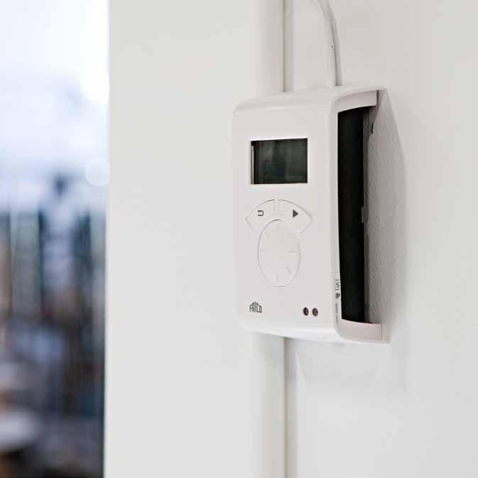
200 Controls Controls


201 Controls 200 SIRe 212 Other controls 214 Thermostats 218 control Controls 199

202 SIRe Control system SIRe Control system The vast majority of our air curtains are supplied with the SIRe intelligent control system, which is built in and controls the air curtain automatically. The air curtain adapts to the existing conditions in the entrance. By sensing how often the door opens/closes, outdoor temperature, indoor temperature or even the return water temperature, the air curtain will give you the most effective protection with the highest energy efficiency. Install and forget With SIRe control system, the air curtain will always perform at its best. You ll never have to think about switching it on or off. It even adapts to the season outside, and with calendar function the air curtain automatically runs during the hours it is needed. Intelligent Automatically adapts to your entrance The air curtain automatically adapts to your entrance conditions. Depending on how often the door is opened/closed, or if it is left open continually, the integrated SIRe controls the air curtain operation so that optimal comfort and energy efficiency is achieved. Proactive Anticipates for quicker reactions By measuring the outdoor temperature, the air curtain is always a step ahead. The integrated regulation ensures that the air curtain is prepared for changes in the outdoor temperature. For example, when a warm spring day turns into a chilly evening. The air speed is adjusted depending on the outdoor temperature change and stops the chill before it penetrates the premises. Adaptive Expert on your entrance SIRe has the capacity to learn precisely what happens at your entrance. The air curtain adapts so that it is always ready to operate fully as soon as the door is opened. It also considers the acoustic comfort by ensuring that the air curtain does not switch between high and low speeds too often. 200
 or completely control all functions and receive indications from your air")
203 SIRe Control system BMS solutions Endless possibilities With our intelligent SIRe control system, the possibilities to control your air curtains via BMS are endless. You can either choose to control your air curtain by 0-10 V signals (controlling on/off, fan speed, heating and alarm) or completely control all functions and receive indications from your air curtain via gateway (two threaded) BUS communication. Calendar function Presets as required SIRe has a calendar function for all the days of the week. The air curtain starts in the morning to ensure that it s always working to create a comfortable climate and save energy. Preset default setting may easily be adjusted by the user. Open/closed door Regulation of air and heat output Outdoor temperature Simple installation Plug and play An air curtain with integrated SIRe control system is easy to install. The different components are supplied together and are easy to assemble. The system selfchecks that everything is correct and that it functions. Thanks to the preset default settings it is easy to start air curtain operation as soon as the system is in place. Room temperature Eco mode Save money and the environment at the same time With SIRe intelligent regulation integrated in your air curtain, you get comfort in your entrance without wasting energy. If you want to increase the energy efficiency further, set SIRe in Eco mode. The air curtain then uses as little energy as possible without compromising too much on comfort. Energy savings of up to 35 percent are possible. 201
204 SIRe Control system Advanced Competent Basic Manual operation Manual regulation of the fan and heat Automatic mode Regulates the fan and heat via thermostat Flexible mode Adapted operation for doors that open/close frequently Open mode Adapted operation for doors that stay open Calendar function Adapted operation according to the day of the week SIRe is an intelligent and well designed low voltage control system which can be customised for each unique application and environment. SIRe is supplied pre-programmed with quick fit plug connections and is very easy to use and install. SIRe learns the requirements in the entrance it is installed in (e.g. opening frequency and outdoor temperature). It has calendar function and selectable switch off at set temperatures for up to nine units. Because the fan speed is adapted, the sound level is optimized and is never higher than is necessary for comfort. With SIRe Advanced it is possible to choose between Eco and Comfort mode dependent on whether energy savings or optimal comfort has been prioritised. The return water temperature can be limited, thus ensuring that the available heat is exploited to the maximum. SIRe can control up to nine units. If more than one air curtain should be controlled by a single SIRe, an additional modular cable SIReCC RJ12 (6p/6c) per unit is needed. Cables between units can easily be joined together by using joint piece SIReCJ6. There are three different levels with different functionality to choose from, Basic, Competent or Advanced. Filter alarm Indicates when the filter needs replacing/ cleaning Simple BMS-system BMS can control on/off, fan speed and alarm functions Eco mode Comfort mode Extra energy-efficient mode Operating mode when comfort is more important Proactive regulation Max limit for return water temperature Exploits the heat that is available to the maximum Measures outdoor temperatures for proactive reaction Advanced BMS-system BMS has advanced control of the air curtain and can receive status indications Functions SIReB Basic Manual regulation of the fan and temperature Automatic control of fan speed and temperature with integrated thermostat. Functions SIReAC Competent All functions for Basic Calendar function Filter alarm Simple BMS control - on/off, fan speed and alarm functions Flexible mode - for doors that open and close frequently Open mode - for doors that stay open Ready for gateway BMS Complete control and indication via BUScommunication Functions SIReAA Advanced All functions for Competent Eco mode - extra energy-efficient mode Comfort mode - when comfort is important Advanced BMS control Proactive regulation measures outdoor temperatures for proactive reaction. Control system SIRe Description SIReB SIReAC SIReAA Control system SIRe Basic Control system SIRe Competent Control system SIRe Advanced 202
205 X5 C2 X5 C2 X5 C2 X4 C1 X4 C1 X4 C1 X3 ROOM X3 ROOM X3 ROOM PE N L SUPPLY 230V ACTUATOR 230V PE N L SUPPLY 230V ACTUATOR 230V PE N L SUPPLY 230V ACTUATOR 230V SIRe Control system Integrated in the air curtain SIReB1/B2, integrated PC Board Base SIReIT, internal temperature sensor SIReUA1 Wall unit cover SIReA1X SIReOTX SIReDC SIReCC Included in SIReAA Advanced: SIReUA1, control unit. Wall unit cover included. SIReA1X, PC board HUB Advanced SIReOTX, outdoor temperature sensor SIReDC, door contact SIReCC, modular cables, RJ12(6p/6c), 3 m resp. 5 m Options: SIReRTX, external room temperature sensor, RJ11 (4p/4c), 10 m SIReUR, kit for recessed installation SIReWTA, clamp-on sensor, RJ11 (4p/4c), 3 m VMO(P), (pressure independent) modulating valve kit or VMT, three way valve and modulating actuator Integrated in the air curtain SIReB1/B2, integrated PC Board Base SIReIT, internal temperature sensor SIReUA1 Wall unit cover SIReC1X SIReDC SIReCC Included in SIReAC Competent: SIReUA1, control unit. Wall unit cover included. SIReC1X, PC board HUB Competent SIReDC, door contact SIReCC, modular cables, RJ12(6p/6c), 3 m resp. 5 m Options: SIReRTX, external room temperature sensor, RJ11 (4p/4c), 10 m SIReUR, kit for recessed installation VOS(P), (pressure independent) valve kit on/off or VOT, three way valve and actuator on/off SIReUA1 IP30 Integrated in the air curtain SIReUB1 IP30 SIReA1X IP10 SIReC1X IP10 SIReOTX SIReIT IP65 IP65 SIReB1/B2, integrated PC Board Base SIReIT, internal temperature sensor SIReUB1 SIReCC SIReRTX SIReUR SIReWTA IP30 IP30 IP65 Included in SIReB Basic: SIReUB1, control unit. Wall unit cover included. SIReCC, modular cable, RJ12(6p/6c), 5 m Options: SIReRTX, external room temperature sensor, RJ11 (4p/4c), 10 m VOS(P), (pressure independent) valve kit on/off or VOT, three way valve and actuator on/off 203
206 SIRe Control system Air conditioner control Building Management System Elevator control Fire alarm system SIReRTX SIReUR SIReCC Entrance control Air curtain control SIReWTA SIReCJ4 SIReCJ6 SIRe control system - options SIReRTX, external room temperature sensor Used to obtain a better measuring point in the premises when the control unit is located so that the internal room temperature sensor does not show a relevant value. 10 m. cable with modular connector RJ11 (4p/4c). SIReUR, kit for recessed installation Kit for installing SIReUA1 recessed in a wall. Only protrudes 11 mm from the wall. SIReWTA, clamp-on sensor Clamp-on sensor for return water temperature control. 3 m. cable with modular connector RJ11 (4p/4c). Should be mounted on the return pipe on the heating coil. SIReCJ4/SIReCJ6, joint piece Used to join two RJ11 (4p/4c) respectively RJ12 (6p/6c). SIReCC, modular cables Modular cables RJ11 (4p/4c) respectively RJ12 (6p/6c). Available in lengths 3, 5, 10 and 15 m. Integration of Frico air curtains in an overall control system (BMS) BMS-control - level 1 With SIRe Competent the air curtains can be integrated in an overall control system (BMS). The air curtain can be started/stopped and the fan speed regulated via the BMS system. A 5-30V control signal is required for starting/stopping. A 0-10V control signal is required to control the fan speed. Potential free contact for buzzer. BMS-control - level 2 With SIRe Advanced the air curtains can be integrated in an overall control system (BMS). The air curtain can be started/stopped, the fan speed and heating regulated smoothly via the BMS system. A 5-30V control signal is required for starting/stopping. A 0-10V control signal is required to control the fan speed and heating. Input for alarm and night reduction via external potential free contact. Potential free contact for buzzer and operation indication. BMS-control - level 3 With SIRe Advanced it is also possible to communicate via Modbus RTU (RS485). Contact Frico for more information. Accessories - SIRe Description SIReRTX SIReUR SIReWTA SIReCJ4 SIReCJ6 SIReCC603 SIReCC605 SIReCC610 SIReCC615 SIReCC403 SIReCC405 SIReCC410 SIReCC415 External room temperature sensor, IP30 Kit for recessed installation, IP30 Clamp-on sensor, IP65 Used to join two RJ11(4/4) Used to join two RJ12(6/6) Modular cable RJ12(6/6) 3 m Modular cable RJ12(6/6) 5 m Modular cable RJ12(6/6) 10 m Modular cable RJ12(6/6) 15 m Modular cable RJ11(4/4) 3 m Modular cable RJ11(4/4) 5 m Modular cable RJ11(4/4) 10 m Modular cable RJ11(4/4) 15 m 204
207 X5 C2 X4 C1 X3 ROOM PE N L SUPPLY 230V ACTUATOR 230V SIRe Control system Wiring diagrams - SIReB Basic Unit without heating SIReB1 SIReB1/B2 C2 Pot. X5 Unit ID C1 X4 ROOM X3 ACTUATOR SUPPLY 230V~ SIReUB1 N L PE PE N L SIReB2 (PA2500) Parallel connection SIReB1/B2 SIReB1/B2 230V~ 230V~ SIReUB1 C2 Pot. X5 Unit ID C1 X4 ROOM X3 ACTUATOR SUPPLY C2 Pot. X5 Unit ID C1 X4 ROOM X3 ACTUATOR SUPPLY N L PE PE N L N L PE PE N L Unit with electrical heating SIReB1/B2 C2 C1 ROOM Pot. X5 X4 X3 Unit ID ACTUATOR SUPPLY 230V~ SIReRTX (optional) SIReUB1 N L PE PE N L Parallel connection SIReB1/B2 C2 C1 ROOM Pot. X5 X4 X3 Unit ID ACTUATOR SUPPLY N L PE PE N L SIReB1/B2 230V~ 230V~ C2 C1 ROOM Pot. X5 X4 X3 Unit ID ACTUATOR SUPPLY N L PE PE N L SIReRTX (optional) SIReUB1 205
208 X5 C2 X4 C1 X3 ROOM PE N L SUPPLY 230V ACTUATOR 230V C SIRe Control system Wiring diagrams - SIReB Basic Unit with water heating SIReB1 SIReB1/B2 C2 C1 ROOM Pot. X5 X4 X3 Unit ID ACTUATOR SUPPLY 230V~ SD230 SIReRTX (optional) SIReUB1 N L PE PE N L SIReB2 (PA2500) Parallel connection SIReB1/B2 SD230 C2 Pot. X5 Unit ID C1 X4 ROOM X3 ACTUATOR SUPPLY 230V~ N L PE PE N L SIReB1/B2 SD230 C2 Pot. X5 Unit ID C1 X4 ROOM X3 ACTUATOR SUPPLY 230V~ N L PE PE N L SIReB1/B2 C2 C1 ROOM Pot. X5 X4 X3 Unit ID ACTUATOR SUPPLY 230V~ SD230 SIReRTX (optional) SIReUB1 N L PE PE N L 206
209 X5 C2 X4 C1 X3 ROOM PE N L SUPPLY 230V ACTUATOR 230V SIRe Control system Wiring diagrams - SIReAC Competent Unit without heating SIReB1 SIReB2 (PA2500) SIReB1/B2 SIReC1X C2 Pot. X5 Unit ID C1 X4 ROOM X3 230V~ COM 1 COM 2 ROOM N L PE PE N L SIReDC SIReUA1 SIReC1X ALARM OUT (BMS) Door contact External ON/OFF Ext. speed ctrl. 0-10V DC IN External alarm IN External night reduction EXTERNAL SETBACK TEMP. ON/OFF (potential free contact) EXTERNAL ALARM IN (potential free contact) EXTERNAL RPM 0-10V DC IN EXTERNAL ON/OFF, 5-30V AC/DC ALARM OUT (BMS) (potential free contact, max 3A, 230V) Parallel connection Pot. Unit ID Pot. Unit ID SIReB1/B2 230V~ SIReC1X COM 1 COM 2 BUS ROOM SIReB1/B SIReUA1 C2 Pot. X5 Unit ID SIReB1/B2 C2 Pot. X5 Unit ID C1 X4 C1 X4 ROOM X3 ROOM X3 ACTUATOR SUPPLY N L PE PE N L ACTUATOR SUPPLY N L PE PE N L 230V~ 230V~ EXTERNAL ALARM IN (potential free contact) EXTERNAL SETBACK TEMP. ON/OFF (potential free contact) EXTERNAL RPM 0-10V DC IN EXTERNAL ON/OFF, 5-30V AC/DC ALARM OUT (BMS) (potential free contact, max 3A, 230V) SIReDC 207
210 X5 C2 X4 C1 X3 ROOM PE N L SUPPLY 230V ACTUATOR 230V SIRe Control system Wiring diagrams - SIReAC Competent Unit with electrical heating SIReB1 SIReB2 (PA2500) SIReRTX (optional) SIReB1/B2 SIReC1X Pot. C2 Unit ID X5 C1 X4 ROOM X3 230V~ COM 1 COM 2 ROOM N L PE PE N L SIReDC SIReUA1 SIReC1X ALARM OUT (BMS) Door contact External ON/OFF Ext. speed ctrl. 0-10V DC IN External alarm IN External night reduction EXTERNAL SETBACK TEMP. ON/OFF (potential free contact) EXTERNAL ALARM IN (potential free contact) EXTERNAL RPM 0-10V DC IN EXTERNAL ON/OFF, 5-30V AC/DC ALARM OUT (BMS) (potential free contact, max 3A, 230V) Parallel connection Pot. Unit ID Pot. Unit ID SIReB1/B2 SIReRTX (optional) 230V~ C2 Pot. X5 Unit ID C1 X4 ROOM X3 ACTUATOR SUPPLY N L PE PE N L SIReC1X COM 1 COM 2 BUS ROOM SIReB1/B SIReUA1 C2 Pot. X5 Unit ID SIReB1/B2 C2 Pot. X5 Unit ID C1 X4 C1 X4 ROOM X3 ROOM X3 ACTUATOR SUPPLY N L PE PE N L ACTUATOR SUPPLY N L PE PE N L 230V~ 230V~ EXTERNAL ALARM IN (potential free contact) EXTERNAL SETBACK TEMP. ON/OFF (potential free contact) EXTERNAL RPM 0-10V DC IN EXTERNAL ON/OFF, 5-30V AC/DC ALARM OUT (BMS) (potential free contact, max 3A, 230V) SIReDC 208
211 X5 C2 X4 C1 X3 ROOM PE N L SUPPLY 230V ACTUATOR 230V SIRe Control system Wiring diagrams - SIReAC Competent Unit with water heating SIReB1 SIReB2 (PA2500) SIReRTX (optional) SIReB1/B2 SD230 SIReC1X C2 Pot. X5 Unit ID C1 X4 ROOM X3 230V~ COM 1 COM 2 ROOM N L L ~ PE N L SIReDC SIReUA1 SIReC1X ALARM OUT (BMS) Door contact External ON/OFF Ext. speed ctrl. 0-10V DC IN External alarm IN External night reduction EXTERNAL SETBACK TEMP. ON/OFF (potential free contact) EXTERNAL ALARM IN (potential free contact) EXTERNAL RPM 0-10V DC IN EXTERNAL ON/OFF 5-30V AC/DC ALARM OUT (BMS) (potential free contact, max 3A, 230V) Parallel connection SIReB1/B2 SD230 C2 Pot. X5 Unit ID C1 X4 ROOM X3 ACTUATOR SUPPLY N L L PE N L ~ 230V~ SIReB1/B2 SD230 SIReRTX (optional) C2 Pot. X5 Unit ID C1 X4 ROOM X3 ACTUATOR SUPPLY N L L PE N L ~ 230V~ SIReC1X COM 1 COM 2 ROOM SIReDC SIReUA1 SIReB1/B2 C2 Pot. X5 Unit ID C1 X4 ROOM X3 ACTUATOR SUPPLY N L L PE N L ~ 230V~ SD230 EXTERNAL SETBACK TEMP. ON/OFF (potential free contact) EXTERNAL ALARM IN (potential free contact) EXTERNAL RPM 0-10V DC IN EXTERNAL ON/OFF, 5-30V AC/DC ALARM OUT (BMS) (potential free contact,max 3A, 230V) 209
212 X5 C2 X4 C1 X3 ROOM PE N L SUPPLY 230V ACTUATOR 230V SIRe Control system Wiring diagrams - SIReAA Advanced Unit with electrical heating SIReB1 SIReB2 (PA2500) SIReB1/B2 SIReUA1 C2 Pot. X5 Unit ID C1 X4 ROOM X3 ACTUATOR SUPPLY N L PE PE N L 230V~ SIReA1X SIReRTX (optional) COM 1 COM 2 BUS ROOM SIReA1X Operation indication OUT (BMS) ALARM OUT (BMS) Door contact External ON/OFF Ext. Heating control 0-10V DC IN Ext. speed ctrl. 0-10V DC IN External alarm IN External night reduction Outdoor temp. sensor Heating indication RPM indication RPM INDICATION 0-10V DC out (max 5 ma) HEAT INDICATION 0-10V DC out (max 5 ma) EXTERNAL SETBACK TEMP. on/off (potential free contact) EXTERNAL ALARM IN (potential free contact) EXTERNAL RPM 0-10V DC IN EXTERNAL HEAT 0-10V DC IN EXTERNAL ON/OFF, 5-30V AC/DC ALARM OUT (BMS) (potential free contact, max 3A, 230V) BMS INDICATION OUT (potential free contact max 3A, 230V) SIReDC SIReOTX Parallel connection Pot. Unit ID Pot. Unit ID SIReUA1 SIReB1/B2 C2 Pot. X5 Unit ID C1 X4 ROOM X3 ACTUATOR SUPPLY N L PE PE N L 230V~ SIReA1X COM 1 COM 2 BUS ROOM SIReRTX (optional) SIReB1/B C2 Pot. X5 Unit ID SIReB1/B2 C2 Pot. X5 Unit ID C1 X4 C1 X4 ROOM X3 ROOM X3 ACTUATOR SUPPLY N L PE PE N L ACTUATOR SUPPLY N L PE PE N L 230V~ 230V~ RPM INDICATION 0-10V DC out (max 5 ma) HEAT INDICATION 0-10V DC out (max 5 ma) EXTERNAL SETBACK TEMP. on/off (potential free contact) EXTERNAL ALARM IN (potential free contact) EXTERNAL RPM 0-10V DC IN EXTERNAL HEAT 0-10V DC IN EXTERNAL ON/OFF, 5-30V AC/DC ALARM OUT (BMS) (potential free contact, max 3A, 230V) BMS INDICATION OUT (potential free contact max 3A, 230V) SIReDC SIReOTX 210
213 X5 C2 X4 C1 X3 ROOM PE N L SUPPLY 230V ACTUATOR 230V SIRe Control system Wiring diagrams - SIReAA Advanced Unit with water heating SIReB1 SIReB2 (PA2500) SIReB1/B2 SIReUA1 C2 Pot. X5 Unit ID C1 X4 ROOM X3 ACTUATOR SUPPLY N L L PE N L ~ 230V~ SIReA1X COM 1 COM 2 BUS ROOM SIReRTX (optional) Blue White SIReDC SIReOTX ST23024 SDM24 Blue White Red Black RPM INDICATION 0-10V DC out (max 5 ma) EXTERNAL SETBACK TEMP. on/off (potential free contact) EXTERNAL ALARM IN (potential free contact) EXTERNAL RPM 0-10V DC IN EXTERNAL HEAT 0-10V DC IN EXTERNAL ON/OFF, 5-30V AC/DC ALARM OUT (BMS) (potential free contact, max 3A, 230V) BMS INDICATION OUT (potential free contact max 3A, 230V) Parallel connection SIReUA1 SIReB1/B2 ST23024 SDM24 C2 Pot. X5 Unit ID C1 X4 ROOM X3 ACTUATOR SUPPLY N L L PE N L ~ 230V~ 24V Blue White Red Black SIReA1X SIReRTX (optional) COM 1 COM 2 BUS ROOM Red Black SIReB1/B2 ST23024 SDM C2 C1 Pot. X5 X4 Unit ID SIReB1/B2 C2 C1 Pot. X5 X4 Unit ID 230V~ ROOM X3 ACTUATOR SUPPLY N L L PE N L ~ 24V ROOM X3 ACTUATOR SUPPLY N L L PE N L ~ 230V~ Red Black ST V Blue White Red Black SDM24 Blue White Red Black RPM INDICATION 0-10V DC out (max 5 ma) Blue White EXTERNAL SETBACK TEMP. on/off (potential free contact) EXTERNAL ALARM IN (potential free contact) EXTERNAL RPM 0-10V DC IN EXTERNAL HEAT 0-10V DC IN EXTERNAL ON/OFF, 5-30V AC/DC ALARM OUT (BMS) (potential free contact, max 3A, 230V) BMS INDICATION OUT (potential free contact max 3A, 230V) SIReDC SIReOTX Red Black 211
214 Other controls ADSR54 PKDM12 RTRD7 RTRD14 RTRDU7 ADSR54, stepless fan speed control For unheated and water heated air curtains (single phase supply 230 V~, max 3 A). Controls the motor without causing disturbing electro magnetic noise. Can be controlled with an external 0 10 V signal. Max. input 3 A, 230 V~. IP54. PKDM12, stepless fan speed control For AC500 and AGI. The appropriate fan speed is set for open and closed door respectively (high/low speed). The fan speed can be controlled with an external 0 10 V signal. Max input 12 A. IP54. RTRD7, 5-step fan speed control For AC500 and AGI. With RTRD7 the air velocity is adjusted in 5 steps for optimum efficiency. The air velocity is set to accommodate different external conditions. Max input 7 A. IP21. RTRD14, 5-step fan speed control For AC500 and AGI. With RTRD14 the air velocity is adjusted in 5 steps for optimum efficiency. The air velocity is set to accommodate different external conditions. Max input 14 A. IP21. RTRDU7, 5-step fan speed control (high/low speed) For AC500 and AGI. With RTRDU7 the air velocity is set in 5 steps for maximum efficiency. When the door is closed the fan runs at a preset low speed to keep the room warm, when the door is open the fan is preset at a high speed to accommodate different external conditions. Max input 7 A. IP21. Description HxWxD [mm] ADSR54 Variable fan speed control 284x240x115 PKDM12 Variable fan speed control, max 12A 316x270x143 RTRD7 5-step fan speed control, max. 7A 309x262x160 RTRD14 5-step fan speed control, max. 14A 290x400x166 RTRDU7 5-step fan speed control (high/low speed), max. 7A 290x400x
215 Other controls MDC MDCDC AGB304 KUR CBT MDC, magnetic door contact with time relay Starts the air curtain or increases from low to high speed when the door is opened. When the door is closed, the fan continues to run for the preset time (2 s 10 min). This prevents the fan from starting/ stopping continuously and is especially suitable for doors that are frequently opened. Three alternating voltfree contacts 10 A, 230 V~ activated when the contacts make. A MDCDC is included in MDC. IP44. MDCDC, magnetic door contact Indicates door status. Extra MDCDC are used when several doors are connected to a MDC. IP44. KUR, digital time switch Digital weekly timer with 8 different program steps (36 memory places) equipped with a changeover contact. Max. breaking current: 10 A. IP55. CBT, electronic timer Electronic timer with alternating contact. Setting range 1/ or hours respectively. The setting range can be limited down to a maximum time of 1/2 hours. IP44. AGB304, position limit switch Starts the air curtain or activates a fan speed control when the door is opened. When the door closes, AGB304 stops the air curtain or changes fan speed through a fan speed control. Alternating contact 4 A, 230 V~. IP44. Description HxWxD [mm] MDC Magnetic door contact with time relay 155x87x43 MDCDC Magnetic door contact AGB304 Position limit switch KUR Digital time switch 175x85x105 CBT Electronic timer 155x87x43 213

216 Thermostats T10 TK10 TKS16(400) TD10 RTI2 RTI2V RTS01 T, TK, TD, basic offer thermostats Processor controlled thermostats for room/floor heating. Available with concealed/visible knob or digital display. Model with visible knob also available with switch and in 400 V. On/off control (for slow systems) or proportional control (for faster systems) in the same thermostat. TD10 has adjustable P-band and time of cycle. Internal and/or external sensors (external sensor RTS01 available as an accessory) give the possibility of selecting the sensor function e.g limiting external sensors (min/max). Save reduction either by built-in manual switch or via external timer. CE compliant. RTI2, electronic 2-step thermostats Processor controlled 2-step thermostats for room heating /cooling. Available with concealed or visible knob. Adjustable temperature difference between the steps (1 10 degrees). Save reduction via external connection timer (1 10 degrees). External sensor (RTS01) available as an accessory. High protection class (IP44). CE compliant. RTS01, external sensor (accessory) External sensor of NTC-type 10 Kohm. 3 m cable included. KRT1900/1901 KRT2800 KRTV19 TBK10 TBKS10 KRT, capillary tube thermostats Capillary tube thermostats for room heating/cooling. Available with concealed and visible knob, and control in 1 or 2 steps. KRT2800 controls in 2 steps and has adjustable temperature difference between the steps (1 4 degrees). KRT1901 has a temperature range of C. High protection class (IP44 resp. IP55). CE compliant. TBK, bimetal thermostats Mechanical bimetal thermostats with acceleration resistance for room heating/cooling. TBKS10 also has a 1-pole switch. CE compliant. 214
217 Thermostats Technical specifications Voltage Max Setting Limit Save Proportional Static Protection Dimensions (supply) [V] input [A] range floor heating reduction [K] control*¹ [K/min] differential [K] class HxWxD [mm] T10 230V~ K/10min 0,5 IP30 80x80x31 TK10 230V~ K/10min 0,5 IP30 80x80x31 TKS16 230V~ K/10min 0,5 IP30 80x80x39 TKS V2~ K/10min 0,5 IP30 80x80x39 TD10 230V~ Adjustable Adjustable 0,3 IP30 80x80x31 RTI2 230V~ 16/10, 230/400V~ Adjustable - 0,5 IP44 155x87x43 RTI2V 230V~ 16/10, 230/400V~ Adjustable - 0,5 IP44 155x87x43 KRT /10, 230/400V~ ,0 IP55 165x57x60 KRT /10, 230/400V~ ,0 IP55 165x57x60 KRTV19-16/10, 230/400V~ ,0 IP44 165x57x60 KRT /10, 230/400V~ ,0 IP55 165x57x60 TBK10 230V~ ,5 IP30 85x82x39 TBKS10 230V~ ,5 IP30 80x80x43 *¹) P-band [K]/time of cycle [min] *²) Only resistive loads, no contactors. Products beginning with T can be read as follows: K=knob, S=switch, D= digital display, B=bimetal. Functions Basic offer Electronic 2-step Capillary tube Bimetal T10 TK10 TKS16(400) TD10 RTI2 RTI2V KRT1900/1901 KRTV19 KRT2800 TBK10 TBKS10 Internal sensor X X X X X X X X X X X External sensor X*¹ X*¹ X*¹ X*¹ X*¹ X*¹ Save reduction X*² X*² X*² X*² X*² X*² 1-pole switch X X X Volt free contact X X X X X X X X X Contact, 1-pole closing X X X Contact, 1-pole alternating X X X X X X X Digital display Advanced extra functions*³ Internal setting X X X X Processor controlled X X X X X X Bimetal acc.resistor X X Capillary tube X X X Fits wall box system X X X X X X Heating or cooling function X X X X X X X X X 2-step X X X Adjustable temp.diff. between the steps *¹) External sensor (RTS01) as accessory. *²) Can be used with an external timer. *³) See manuals on X X X X X 215
218 Thermostats Wiring diagrams T, TK, TD, basic offer thermostats T10/ 10A / 230V~ (AC1) TK10 TD10 10A / 230V~ (AC1) T10 >t C Sensor A/B >t C Sensor A/B TD10 TK10 N L 230V~ LOAD Sensor N L 230V~ LOAD Sensor 2-polig brytning / 2-pole switching TKS16/ 16A / 230V~ (AC1) TKS A / 400V2~ (AC1) TKS16/ 16A / 230V~ (AC1) TKS A / 400V2~ (AC1) >t C >t C TKS16 42o Sensor A/B 42o Sensor A/B TKS16400 TKS16400 N L L1 L2 230V~/ 400V2~ LOAD Sensor N L L1 L2 230V~/ 400V2~ LOAD Sensor TKS16 RTI2, electronic 2-step thermostats RTI2/ RTI2V >t C Hi 16A / 230V~ (AC1) 10A / 400V2~ (AC1) >t C Lo RTI L L N RTI2V Sensor LOAD LOAD L N L N (L2) (L2) 230V~ / 230V~ / 400V2~ 400V2~ L N 230V~ 216
219 15 25 CBT 1 2 ON Thermostats and controls Wiring diagrams KRT, capillary tube thermostats KRT(V) 16A / 230V~ (AC1) 19(00) 10A / 400V2~ (AC1) >t C KRT A / 230V~ (AC1) 10A / 400V2~ (AC1) >t C Hi >t C Lo KRT KRT2800 LOAD LOAD LOAD KRTV19 N (L2) L N L (L2) 230V~ / 400V2~ N L (L2) 230V~ / 400V2~ TBK, bimetal thermostats TBK10 >t C TBKS10 >t C TBK10 TBKS10 LOAD LOAD L N 230VAC L N 230VAC KUR, digital time switch CBT, electronic timer KUR 16A / 230V~ (AC1) CBT 16A / 230V~ 4h 2h 1h KUR L N L N CBT LOAD LOAD L N 230V~ L N 230V~ 217

220 control
221 control Choose valve kit heated units that are controlled by SIRe are supplemented with valve kits. It s easy to choose the right valve kit. Look at the guide for the level of SIRe chosen - Basic, Competent or Advanced and select the valve kit which suits the system requirements and characteristics. SIRe Basic, SIRe Competent VOS, valve kit on/off Complete kit with two way control and adjustment valve, on/off-actuator, shut-off valve and bypass. VOS15LF Kvs 0,90 Max at 10 kpa: 0,079 l/s DN15 VOS15NF Kvs 1,8 Max at 10 kpa: 0,158 l/s DN15 VOS20 Kvs 3,4 Max at 10 kpa: 0,299 l/s DN20 VOS25 Kvs 7,2 Max at 10 kpa: 0,630 l/s DN25 VOSP, pressure independent valve kit on/off Complete kit with two way pressure independent control and adjustment valve, on/off-actuator, shut-off valve and bypass. Two way pressure independent control and adjustment valve ensures that the always is constant. VOSP15LF Flow range 0,004-0,035 l/s DN15 VOSP15NF Flow range 0,021-0,088 l/s DN15 VOSP20 Flow range 0,035-0,175 l/s DN20 VOSP25 Flow range 0,071-0,353 l/s DN25 VOT, three way control valve and actuator on/off Three way control valve and actuator on/ off. VOT15 Kvs 1,7 Max at 10 kpa: 0,149 l/s DN15 VOT20 Kvs 2,5 Max at 10 kpa: 0,220 l/s DN20 VOT25 Kvs 4,5 Max at 10 kpa: 0,395 l/s DN25 SIRe Advanced VMO, modulating valve kit Complete kit with two way control and adjustment valve, modulating (stepless) actuator and shut-off valve. VMO15LF Kvs 0,40 Max at 10 kpa: 0,035 l/s DN15 VMO15NF Kvs 1,0 Max at 10 kpa: 0,088 l/s DN15 VMO20 Kvs 2,1 Max at 10 kpa: 0,185 l/s DN20 VMO25 Kvs 4,0 Max at 10 kpa: 0,352 l/s DN25 VMOP, pressure independent and modulating valve kit Complete kit with two way pressure independent control and adjustment valve, modulating (stepless) actuator and shutoff valve. Two way pressure independent control and adjustment valve ensures that the always is constant. VMOP15LF Flow range 0,004-0,035 l/s DN15 VMOP15NF Flow range 0,021-0,088 l/s DN15 VMOP20 Flow range 0,035-0,175 l/s DN20 VMOP25 Flow range 0,071-0,353 l/s DN25 VMT, three way control valve and modulating actuator Three way control valve and modulating actuator. VMT15 Kvs 1,7 Max at 10 kpa: 0,149 l/s DN15 VMT20 Kvs 2,5 Max at 10 kpa: 0,220 l/s DN20 VMT25 Kvs 4,5 Max at 10 kpa: 0,395 l/s DN25 Design and specifications are subject to change without notice.
222 control VOS TBVC SD230 AV BPV10 SD230 VOS, valve kit on/off Two way combined control and adjustment valve with on/off actuator, shut-off valve and bypass. DN15/20/ V. Used with SIRe Basic and Competent The valve kit consists of the following: TBVC, regulation and adjustment valve SD230, actuator on/off 230V AV, shut off valve BPV10, bypass valve AV, shut off valve The shut off valve consists of a ball valve which is either open or closed and is used to shut off the, when servicing for example. TBVC, regulation and adjustment valve The regulation and adjustment valve can be used to finely adjust or shut off the water manually. The water is set using the adjustment tool (option). The regulation and adjustment valve also has a shut off function, which makes maintenance easier, and a self sealing measurement outlet which allows for easy and fast measurements. TBVC BPV10 BPV10, by-pass valve If the valve is closed, a low passes through the by-pass valve (BPV10) so that there is always hot water in the water coil. This is to provide quick heat supply when a door is opened but also to provide a degree of frost protection. SD230, actuator The actuator controls the heat supply on/off. In unpowered mode SD230 is open. The valve kit is available in three different valve dimensions, DN15 (1/2 ), DN20 (3/4 ) and DN25 (1 ). The by-pass valve is DN10 (3/8"). Used with SIRe Basic and Competent or supplemented with suitable thermostat. Voltage [V] Connection Kvs VOS15LF* 230V DN15 0,90 VOS15NF 230V DN15 1,8 VOS20 230V DN20 3,4 VOS25 230V DN25 7,2 *) Low AV Accessories VAT, adjustment tool for valve kit VOS, VOSP, VMO, VMOP With the adjustment tool the water can be accurately and easily set. VAT
223 control VOSP TBVCMP SD230 AV BPV10 VOSP, pressure independent valve kit on/off Two way pressure independent control and adjustment valve with on/off actuator, shut-off valve and bypass. DN15/20/ V. Used with SIRe Basic and Competent. SD230 TBVCMP BPV10 AV The valve kit consists of the following: TBVCMP, pressure independent regulation and adjustment valve SD230, actuator on/off 230V AV, shut off valve BPV10, bypass valve AV, shut off valve The shut off valve consists of a ball valve which is either open or closed and is used to shut off the, when servicing for example. TBVCMP, regulation and adjustment valve The regulation and adjustment valve can be used to finely adjust or shut off the water manually. TBVCMP is independent of the available differential pressure, which contributes to stable and accurate regulation (ensures the correct to the heater even if the differential pressure in the rest of the pipe system changes). The water is set using the adjustment tool (option). With the regulation and adjustment valve easy flush-through is also possible, which makes for easy and fast maintenance. BPV10, by-pass valve If the valve is closed, a low passes through the by-pass valve (BPV10) so that there is always hot water in the water coil. This is to provide quick heat supply when a door is opened but also to provide a degree of frost protection. SD230, actuator The actuator controls the heat supply on/off. In unpowered mode SD230 is open. The valve kit is available in three different valve dimensions, DN15 (1/2 ), DN20 (3/4 ) and DN25 (1 ). The by-pass valve is DN10 (3/8"). Used with SIRe Basic and Competent or supplemented with suitable thermostat. Voltage [V] Connection VOSP15LF* 230V DN15 VOSP15NF 230V DN15 VOSP20 230V DN20 VOSP25 230V DN25 *) Low Accessories VAT, adjustment tool for valve kit VOS, VOSP, VMO, VMOP With the adjustment tool the water can be accurately and easily set. VAT
224 control VMO TBVCM SDM24 AV ST23024 SDM24 VMO, modulating valve kit Two way combined control and adjustment valve with modulating actuator and shut-off valve. DN15/20/25. 24V. Used with SIRe Advanced. The valve kit consists of the following: SDM24, modulating actuator 24V TBVCM, regulation and adjustment valve AV, shut off valve ST23024, 24V transformer for valve actuator (in valve kit with 24V) AV, shut off valve The shut off valve consists of a ball valve which is either open or closed and is used to shut off the, when servicing for example. TBVCM, regulation and adjustment valve The regulation and adjustment valve can be used to finely adjust or shut off the water manually. The water is set using the adjustment tool (option). The regulation and adjustment valve also has a shut off function, which makes maintenance easier, and a self sealing measurement outlet which allows for easy and fast measurements. TBVCM SDM24, actuator The actuator (SDM24) is modulating and gives the right temperature. SIRe is set to always allow through a small leak in order to provide a fast heat supply ex. when a door is opened and for some frost protection. The valve kit is available in three different valve dimensions, DN15 (1/2 ), DN20 (3/4 ) and DN25 (1 ). Used with SIRe Advanced or supplemented with suitable thermostat. Voltage [V] Connection Kvs VMO15LF* 24V DN15 0,40 VMO15NF 24V DN15 1,0 VMO20 24V DN20 2,0 VMO25 24V DN25 4,0 *) Low AV Accessories VAT, adjustment tool for valve kit VOS, VOSP, VMO, VMOP With the adjustment tool the water can be accurately and easily set. VAT
225 control VMOP TBVCMP SDM24 AV ST23024 VMOP, pressure independent and modulating valve kit Two way pressure independent control and adjustment valve with modulating actuator and shut-off valve. DN15/20/25. 24V. Used with SIRe Advanced. SDM24 TBVCMP AV The valve kit consists of the following: TBVCMP, pressure independent regulation and adjustment valve SDM24, modulating actuator 24V AV, shut off valve ST23024, 24V transformer for valve actuator (in valve kit with 24V) AV, shut off valve The shut off valve consists of a ball valve which is either open or closed and is used to shut off the, when servicing for example. TBVCMP, regulation and adjustment valve The regulation and adjustment valve can be used to finely adjust or shut off the water manually. TBVCMP is independent of the available differential pressure, which contributes to stable and accurate regulation (ensures the correct to the heater even if the differential pressure in the rest of the pipe system changes). The water is set using the adjustment tool (option). With the regulation and adjustment valve easy flush-through is also possible, which makes for easy and fast maintenance. SDM24, actuator The actuator (SDM24) is modulating and gives the right temperature. SIRe is set to always allow through a small leak in order to provide a fast heat supply ex. when a door is opened and for some frost protection. The valve kit is available in three different valve dimensions, DN15 (1/2 ), DN20 (3/4 ) and DN25 (1 ). Used with SIRe Advanced or supplemented with suitable thermostat. Voltage [V] Connection VMOP15LF* 24V DN15 VMOP15NF 24V DN15 VMOP20 24V DN20 VMOP25 24V DN25 *) Low Accessories VAT, adjustment tool for valve kit VOS, VOSP, VMO, VMOP With the adjustment tool the water can be accurately and easily set. VAT
226 control VOT VMT TRVS SD230 SDM24 TRVS ST23024 VOT, three way control valve and actuator on/off 3-way control valve with on/off actuator, DN15/20/ V. The valve kit consists of the following: TRVS, 3-way control valve SD230, actuator on/off 230V TRVS, 3-way control valve The 3-way valve and the actuator controls the water and provides a basic form of water regulation, without the possibility of adjusting or shutting the water off, e.g. when making maintenance. SD230, actuator The actuator controls the heat supply on/off. In unpowered mode SD230 is open. The valve kit is available in three different valve dimensions, DN15 (1/2 ), DN20 (3/4 ) and DN25 (1 ). Used with SIRe Basic and Competent or supplemented with suitable thermostat. VMT, three way control valve and modulating actuator 3-way control valve with modulating actuator. DN15/20/25. 24V. The valve kit consists of the following: TRVS, 3-way control valve SDM24, modulating actuator 24V ST23024, 24V transformer for valve actuator (in valve kit with 24V) TRVS, 3-way control valve The 3-way valve and the actuator controls the water and provides a basic form of water regulation, without the possibility of adjusting or shutting the water off, e.g. when making maintenance. SDM24, actuator The actuator (SDM24) is modulating and gives the right temperature. SIRe is set to always allow through a small leak in order to provide a fast heat supply ex. when a door is opened and for some frost protection. The valve kit is available in three different valve dimensions, DN15 (1/2 ), DN20 (3/4 ) and DN25 (1 ). Used with SIRe Advanced or supplemented with suitable thermostat. SD230 TRVS SDM24 TRVS Connection Kvs Connection Kvs VOT15 DN15 1,7 VOT20 DN20 2,5 VOT25 DN25 4,5 VMT15 DN15 1,7 VMT20 DN20 2,5 VMT25 DN25 4,5
227 control VR20/25 AV20/25 BPV10 SD20 TRV20/25 JVF20/25 TVV20/25 TRV20/25 SD20 VR 20/25, valve kit* For control of water to water heated air curtains. The valve kit consists of the following: AV20/25, stop valve JVF20/25, adjustment valve TRV20/25, on/off 3-way control valve BPV10, by-pass valve SD20, actuator on/off 230V~ The stop valve (AV20/25) consists of a ball valve which is either open or closed. It is used to turn the water off and on. The water can be fine-tuned manually with the adjustment valve and can also be completely turned off. The water may be read off the valve. The kv value for JVF20 is 3,5 and for JVF25 it is 5,5. If the 3-way valve (TRV20/25) is closed, the through the by-pass valve (BPV10) is low to ensure presence of warm water in the heating coil. This leads to instant heat supply when needed and some degree of frost protection. The actuator (SD20) works on/off. The valve kit is available with two different valve dimensions: VR 20 - DN20 (3/4 ) and VR 25 - DN25 (1 ). The by-pass valve dimension is DN10 (3/8 ). To regulate VR20/25, a suitable thermostat has to be added. TVV20/25, valves + SD20, actuator* TVV20/25, 2-way regulation valve and SD20, actuator on/off provides a basic form of water regulation, without the possibility of adjusting or shutting the water off, e.g. when making maintenance. A suitable thermostat is chosen to regulate TVV20/25 and SD20. DN20/25. TVV20/25, 2-way control valve* TVV20 has a pipe dimension of DN20 (3/4 ) and TVV25 of DN25 (1 ). class PN16. Maximum pressure 2 MPa (20 bar). Maximum pressure TVV20: 100 kpa (1 bar) Maximum pressure TVV25: 62 kpa (0,62 bar) The kv-value is adjustable in 3 steps: TVV20: kv 1,6, kv 2,5 and kv 3,5 TVV25: kv 2,5, kv 4,0 and kv 5,5 TRV20/25, 3-way control valve* If a 3-way valve is preferred, TRV20/25 can be used instead of TVV20/25. SD20, actuator on/off 230V~* SD20 regulates the heat supply. Works on/off. A 5 second closing of the valve prevents sudden pressure changes in the pipe system. In unpowered mode SD20 is closed. TE3434 Flexible hose, length 0,8 metres, for water heated units (2 is needed for a unit) with external thread 3/4 (DN20) at one end and coupling nut internal thread 3/4 (DN20), on the other. SD20 TRV20/25 JVF20/25 SD20 TVV20/25 BPV10 AV20/25 *) These products can not be used together with SIRe control system.

228 Technical handbook 229 The invisible door 230 Why is there a draught from an opening? Temperature differential outdoor/indoor differentials indoor/outdoor Wind stress The total air Important to remember 232 Optimized air curtains 233 Right from the start and the whole way 234 Optimized performance 234 Protects the whole door opening not just where it is least needed 235 Air barrier power = impulse 235 The balance between air volume and air velocity gives optimum performance 236 Optimized air geometry Width of the outlet Outlet grille Minimized turbulence 237 Tests - air geometry Frico 238 Create maximum protection at floor level Test - protective effect 239 Dimensioning 239 Air barrier velocity 240 Tests - performance Air curtain efficiency 242 Tests - performance Impulse at the floor 242 Large air volumes cost 243 Minimized sound level 243 Air intake on the top 243 Turbulence - no thanks 243 Optimized amount of air 244 Sound facts What is sound? How is sound measured? Fundamental concepts Sound power level and sound pressure level 245 Testing - sound


229 246 Adjustment 246 Cold storage and freezer rooms 246 Correct air velocity 246 Entrances and doorways 246 Adjustment adapts your installation 246 Controls takes care of the rest 247 Controls 247 SIRe Control system Basic Competent Advanced BMS Simple installation Other controls 248 Valve kits 248 Select the correct valve kits for units with SIRe For SIRe Basic and Competent For SIRe Advanced 251 Other valve kits 252 Energy saving with air curtains 253 Calculation of energy savings 253 Contact us at Frico for advice 254 Just a click away 254 Smart tools Product selection guide Specification text Heating calculations 255 Tables for dimensioning Basic electrical formulas Symbols for model types Enclosure classes for electrical materials Dimensioning table for cables and wiring Dimensioning table Technical handbook

230 Technical handbook 228

231 Technical handbook The invisible door An open door is inviting and easy to pass through, but it also means a poor working environment and energy loss. An air curtain creates a comfortable environment and minimizes energy loss. Frico air curtains effectively separate indoors from outdoors, hot from cold. Air curtains create an air barrier between hot and cold, both to prevent cold outdoor air from entering, while the heated air is kept inside, and to protect air conditioned premises and refrigerated rooms. A correctly installed air curtain reduces draughts, creates a comfortable indoor environment and reduces energy losses at doors and doorways. Air s out of an unprotected opening. With a correctly set air curtain there is a sharp separation between the different temperature zones. 229
232 Technical handbook Why is there a draught from an opening? The amount of air that s out through an open door depends on differences in pressure between the indoor and outdoor air. This pressure differential is dependent on three factors: Different temperatures indoors and outdoors Different pressures indoors and outdoors Incoming wind speed at the door opening Simply put; if the conditions on one side of the door differ in any way from those on the other side, then there will be a draught from the door opening. Air s out through an open door to equalize the differences in pressure and temperature. In heated premises this means that hot air s out and cold air s in. Wind blowing towards the door also affects the air. Temperature differential outdoor/indoor Warm indoor air has a lower density and is lighter than cold outdoor air. Therefore there is a pressure differential at the door opening. The cold air s in through the lower part of the opening and pushes the hot air through the upper section. The size of the air depends on the temperature differential between outdoor and indoor air. The air exchange is thus dependent on thermal pressure differentials. If the indoor and outdoor temperatures are known, then the density of the outdoor and indoor air can be determined and making it possible to calculate the pressure differential and air through the opening. The air (Q T ) can be calculated using the following equation: differentials indoor/outdoor In order for an air curtain to work well, it is important that there is not too great an overpressure or negative pressure in the premises. Nearly all ventilation systems are mechanically adjusted and are based on the prevailing conditions when they were set. When the external conditions are changed, for example by variations in temperature, air pressure, wind influence and humidity, the balance is disturbed and replaced by positive or negative pressure (usually negative pressure). An air curtain can withstand a maximum of 5 Pa, depending on the conditions. But even small differences in pressure can significantly affect the efficiency of the air curtain. The pressure differential between a building and its surroundings can be equalized using balanced ventilation, which increases comfort and reduces energy costs. Balanced ventilation can be achieved by pressure regulation via the ventilation system, but the most efficient way is to continuously measure the pressure differential between indoors and outdoors and use it to control the ventilation. Contact Frico for more information. Air dependent on pressure differential (Q P ) can be calculated using the following equation: Q P = W H P 2 C d ( P< 5 Pa) ρ Opening W = H = door width [m] door height [m] [ [2] ] P = pressure differential W Q T = H C d g ρ ρ m [ [1] ] Opening W = door width [m] H = door height [m] C d = coefficient g = gravity coefficient (9.81 m/s 2 ) ρ = the air masses' density differential ρ m = the air masses' average density ρ = C d = -18 C +18 C air density coefficient Air caused by thermal pressure differentials. 230
233 Wind stress When the wind blows towards an opening, air s through the opening. The air is assumed to be evenly distributed across the whole door opening. The air is then proportional to the wind speed horizontally against the door opening. (After the pressure build up the air is limited to what escapes through leaks in the building.) A wind speed of 3 m/s corresponds to a load pressure of 5 Pa. The air (Q V ) can be calculated using the following equation: Opening Q v = W H C v v W = H = v = C v = door width [m] Q tot = Q T + Q V + Q P [ [3]] door height [m] wind speed wind direction coefficient = of the horizontal wind load towards the opening of the horizontal wind load towards the opening The total air The total air through open doors is the sum of the caused by temperature and pressure differentials and wind stresses. [ [4] ] Important to remember If there is negative pressure in the building, the efficiency of the air curtain is considerably reduced. The ventilation should therefore be balanced. An air curtain cannot prevent a deficit in the amount of air that is due to unbalanced ventilation (negative pressure). If an opening is exposed to wind it affects the efficiency of the air curtain. An air curtain can withstand a wind speed of up to 3 m/s, depending on the conditions. In an existing opening that is exposed to greater wind loads you may supplement with more heating to improve the comfort. Where there are high wind stresses it is appropriate to supplement the air curtain with a revolving door or an air lock, ideally with the openings offset in relation to each other. The design of the building affects the function of the air curtain. In large buildings that are strongly affected by wind, premises with staircases where the chimney effect occurs and premises with draughts, more powerful curtains are required. Normally the air curtain unit is placed on the inside of the opening to the premises it should protect. When used to protect cold storage or a freezer room, the unit must be mounted on the warm side. The air curtains must be as close to the opening as possible and cover the full width of the opening. The direction and speed of the air should be adjusted to the conditions in the opening. Wind pressure and negative pressure affect the function of air curtains and try to bend the air stream inwards. The air stream should therefore be directed outwards to withstand the load. The total air is the sum of the s caused by temperature and pressure differentials and wind stresses. 231
234 Technical handbook Optimized air curtains Separating climate zones is relatively easy if it is only the temperatures that differ. Handling an opening that is exposed to wind, pressure differentials and unbalanced ventilation is more difficult. Frico air curtains reduce the problems by creating an air barrier with the perfect balance between air volume and air velocity. Frico has been developing air curtains for the demanding Scandinavian climate for 40 years. Our experience and knowledge has resulted in Thermozone technology, the theoretical foundation that we base the development of our air curtains on. Thermozone technology gives optimum curtain effect with perfect balance between air volume and air velocity. This balance does not just make the air curtain more effective but also has other advantages. The indoor climate is more comfortable if the sound level and the turbulence are reduced and the energy costs are lower. Air curtains with Thermozone technology have optimized performance and minimized sound levels. Read more about Thermozone technology on the following pages. R 232

235 A Technical handbook B C Right from the start and the whole way When we start to develop a new product the most important factors are performance and sound level. The designers test their way forward step by step to find a level with optimum performance and the lowest sound level. The turbulence in the unit must be minimized to prevent high pressure s and high energy consumption and to give as low a sound level as possible. To minimize the turbulence, the designers follow the path of the air from the intake grille to the outlet. The shape of the fan housing is very important for the performance of the fan and Athe fan's capacity to increase the pressure. The air must be directed to and from the fans in a natural way and finally leave the unit through the important outlet grille. The width and design of the outlet is very important. The throw is at its most effective when the of air leaving the air curtain is laminar and homogenous throughout the width of the outlet. From the very beginning of development, consideration B is taken to make the product easy to assemble, install and service. The designers are involved in the product the whole way through to manufacture and launch to ensure that the design functions in production terms and that it meets our customers' wishes. C 233


236 Technical handbook Optimized performance Independent tests show that a correctly installed air curtain can reduce energy losses at an open door by up to 80%. A correctly installed air curtain covers the width and height of the opening and is adapted for the stresses that it is exposed to. Protects the whole door opening A correctly installed air curtain creates an air barrier that covers the whole opening and is adapted for the stresses that it is exposed to. In addition to the air curtain air volume, when dimensioning you must set requirements for air velocity at floor level, because that is where the stress is the greatest. You then know that you have an air barrier that reaches the whole way down and gives the best possible protection. The opening is affected by the differences in temperature, pressure and wind stress. The effect is greatest at floor level. By setting requirements for the air velocity at floor level, you have an air curtain that covers the whole door opening....not just where it is least needed Many people evaluate air curtains based on the air volume that they produce without considering the range of the air barrier. The air volume is measured closest to the unit, where the stresses are smallest. If you choose an air curtain based purely on air volume you may get an air curtain that only gives good protection close to the outlet. If you choose an air curtain based purely on air volume you may get an air curtain that only gives good protection close to the outlet, where the impact on the door opening is less. 234
237 Technical handbook Air barrier power = impulse To evaluate an air curtain's performance the term impulse is used, which describes what force an air barrier has. Impulse = air volume x density x air velocity 13 m/s 1900 m 3 /h/m m 8 m/s 3100 m 3 /h/m [kgm/s 2 ] = [m 3 /s] x [kg/m 3 ] x [m/s] The unit for impulse is [kgm/s 2 ], that is Newton (N), the SI unit for force. The impulse can be achieved in different ways. A product with high air velocity and small air can have the same impulse as a product with low air velocity and large air. The impulse must be sufficiently large the whole way down to the floor in order to obtain an effective air barrier across the whole opening. It is therefore important to take air velocity into consideration when dimensioning. A product with high air velocity and small air can have the same impulse as a product with low air velocity and large air. The balance between air volume and air velocity gives optimum performance Thermozone technology creates a balance between air volume and air velocity that gives optimum performance. The design of the outlet is a key factor in achieving this balance. To explain it we usually use the analogy of a hose pipe, because air is physically similar to water. With a hose pipe without a nozzle (large water volume and low pressure) you cannot reach far because the velocity of the water leaving the hose is too low. If you connect the hose to a pressure washer (low water volume and high pressure) the water leaves the pressure washer at high speed, but still does not reach further than a few metres, because of the turbulence created in the water by the high pressure washer. If you then connect the hose to a nozzle, the water volume and pressure can be adjusted and the range of the water jet can be optimized and reach a long way. The performance is reduced in the same way in air curtains with low air velocity and large air or high air velocity and small air. They don't reach the floor. Large air volumes also require more heating and unnecessarily large amounts of energy. Thermozone technology creates a balance between air volume and air velocity that saves energy by using the minimum amount of air and gives optimal efficiency over the whole door opening. > < Large volume, low pressure Small volume, high pressure Ideal relationship between pressure and volume 235
238 Technical handbook Optimized air geometry The designs of the outlet and the inside of the unit are key factors in creating an air barrier that protects efficiently and has a minimal sound level. 1 Width of the outlet At any given air volume, it is the width of the outlet that determines the air velocity. Too small an outlet creates turbulence because of an air velocity which is too high, this shortens the range. If the outlet is too wide it reduces the air velocity and shortens the range. In Frico air curtains the air range is optimized via the width of the outlet. 2 Outlet grille Height, width and fin distance all play a part in the design of the outlet grille, so that the air is directed and turbulence minimized. The result is a controlled air stream and an effective air barrier. & Frico's outlet grilles make it easy to direct the air to resist pressure loads in the opening, so that energy losses are minimized. 3 Minimized turbulence Turbulence inside the air curtain gives higher pressure s and higher energy consumption. In Frico air curtains the turbulence is minimized and the energy consumption is limited. 236


239 Technical handbook Tests - air geometry A practical test of Frico's outlet grilles compared to two competitors shows that the same air volume (2000 m 3 /h) gives different throw lengths depending on the characteristics of the outlet grille. In the test the different manufacturer's outlet grilles were mounted on a neutral construction with fans. Competitor I has too high a speed at the outlet, which gives high turbulence, the speed for competitor II is too low. The result is that the competitors' outlet grilles give significantly shorter throw lengths. Speed [m/s] Large difference in performance 3 m 5 m Frico Competitor I Competitor II Distance [m] CFD analysis of Frico outlet grilles compared to a competitor shows that the same air volume (1800 m 3 /h) gives different throw lengths depending on the characteristics of the outlet grille. In the diagram below we have compared the throw length of a Frico unit with a competitor with an air velocity of at least 3 m/s. The CFD analysis shows that the Frico outlet grille provides an air beam with considerably longer throw length at a velocity of >3m/s. CFD-analysis Frico's outlet grilles m/s Frico m/s Competitor Throw length 3 m/s Throw length 3 m/s Large difference in performance 237


240 Technical handbook Create maximum protection at floor level Too low air velocity at floor level gives a curtain that cannot withstand stresses. Too high velocity gives turbulence that reduces the protective capacity of the air barrier and also has loud sound levels. The correct velocity gives good protection. Thermozone technology gives the most effective air barrier by ensuring that the air stream reaches the floor and at optimal air velocity. Thermozone technology solves the problem with the minimum amount of air. Air velocity is too low Air velocity is too high Correct air velocity Test - protective effect The environment replicated in this test is a dairy section directly attached to a room with normal room temperatue. Different operating cases were studied in a cross-sectional temperature measurement and the values were compiled in a diagram showing how the air streams affect the temperature in the areas around the opening. The clear red colour shows normal room temperature and the darkest blue colour shows the cold storage temperature. The values on the X-axis state the distance in centimetres from the unit, the values on the Y-axis state the distance in centimetres from the floor. Opening without air curtain In an unprotected opening the cold air s out and the cold storage room becomes much too warm. Opening with air curtain, wrong angle If the angle is too small the hot air is blown into the cold storage room. Opening with air curtain, too high speed Excessive speed creates turbulence, which causes energy loss and increases the cold storage temperature. Opening with correctly adjusted air curtain With a correctly set air curtain unit there is a sharp separation between the different temperature zones. 238 The test was made with ADA Cool, model ADAC120, and carried out by technicians from Malmö University.

241 Technical handbook Dimensioning Frico has supplied air curtains for over 40 years and our experience of dimensioning can be illustrated in a diagram. The relationship between the size of the door and how powerful the air curtain needs to be is not linear. The higher the door the greater the force required. We have chosen to use the distance to the floor as reference, together with the air velocity measured in accordance with ISO For an installation height less than 2.5 metres it is usually appropriate to select an air curtain with the capacity to deliver approx 2.5 m/s in a laboratory environment at a distance equal to the installation height. For other heights, see the diagram. Please note that the air velocity at dimensioning is not the velocity the air should have at floor level in an actual installation, but the capacity the unit needs to be able to compensate for the wind loads and pressure differentials occurring in an actual doorway. In many cases there are other factors to refer to, see the section "Important to remember" earlier in the handbook. The air stream direction and velocity must be adjusted at installation to obtain an air curtain that works optimally. Read more about adjustment later in the handbook. Air barrier force 4m/s* 3m/s* 3 Industry Air velocity with distance to floor level according to ISO Commercial Stresses Entrances 2,5m/s* Mindre entréer Större entréer <2,5 m 2,5 m < 4,2 m < 4,2 m <2,5 m 2,5 < 4,2 * = ±0,5 m/s Installation height [m] Air barrier velocity There is an ISO standard to measure the air barrier velocity (ISO Laboratory methods of testing for aerodynamic performance rating). Frico measures all air curtains according to the ISO standard, the result is in the air velocity profile of the relevant product. m 0,1 11,0 m/s 1,0 5,2 m/s 2,0 3,8 m/s 3,0 3,2 m/s 3,5 3,0 m/s ISO measurements at our laboratory in Skinnskatteberg, which is one of the most advanced in heating and ventilation in Europe. Air velocity profile PA
242 Technical handbook Tests - performance Air curtain efficiency Frico has developed a method to test air curtain performance. The test is full scale. The idea is to measure the volume of air that passes through a door with an air curtain is installed in comparison to a door without an air curtain. In the test all stresses are converted to a pressure evenly distributed across the door. Outdoor Indoor Air curtain P [Pa] Q [m³/h] The test installation consists of two rooms that correspond to indoors and outdoors. A powerful fan with equipment to measure air is located between the rooms. The air curtain is installed above the opening. When the fan is run an air is created from one room to the other, exactly the same volume of air passes through the fan as through the opening. This gives rise to a pressure differential (DP) between the two rooms. The fan starts to run at low speed that then slowly increases. Information about air and pressure differential is stored on computer. This data is then used to create a curve, see diagram
243 Technical handbook Without air curtain P[Pa] With Frico air curtain Diagram 1: Air through the opening with and without air curtain at different differential pressures. Air [m 3 /h] and over the opening are measured with and without the air curtain. The result is two curves where the air at a particular pressure differential can be compared. Example: At 3 Pa the air through the opening without the air curtain is 4 m³/s and with the air curtain is 1.6 m³/s. The difference in the air shows the perfomance of the air curtain. In this case it is (4 1.6)/4 100 = 60% less with the air curtain compared to without. Frico, impulse = 19.3 kg x m/s 2, air velocity 13 m/s, air 4500 m 3 /h Competitor 1, impulse = 11.9 kg x m/s 2, air velocity 18m/s, air 2000 m 3 /h Competitor 2, impulse = 22.3 kg x m/s 2, air velocity 9m/s, air 7500 m 3 /h Diagram 2: Air curtains mounted at a height of 3 metres, measured efficiency at different differential pressures. Differential pressure [Pa] This also makes it possible to compare the performance of different products under the same conditions. Diagram 2 shows the result of testing three air curtain units that have been designed using different basic concepts. Competitor 1 has a high air velocity and small air and competitor 2 has a medium air velocity and large air. The air curtain from Frico has an optimized air velocity and air that makes it more efficient than competitor 2 despite ( )/22.3 = approx 13% lower impulse. 241
244 Technical handbook Tests - performance Impulse at the floor A practical test of different air curtains at floor level can be carried out by comparing the air barrier range and power using a wind board. X To directly compare the throw length and power of different air curtains you can position them equidistantly on either side of a wind board and see which way the board moves. At the same air volume, air curtains from Frico give a stronger impulse at ground level than competitors, which means greater protection. Frico air curtains maintain the impulse the whole way to the floor, which gives a lower operating cost, because the same strength of air barrier can be achieved using lower air volume. The angle X indicates the air barrier force (impulse). Y = corresponds to the distance to the floor Y Impulse = air volume x density x air velocity Large air volumes cost 13 m/s 1900 m 3 /h/m 8 m/s 3100 m 3 /h/m Low air velocity can be compensated for by higher air volume to reach the floor. Large air volumes require more heating and therefore cost more. As shown by above test, Frico air curtains can give the same strength to the air barrier at floor level with lower air volume. m m Calculation of output on an air curtain from Frico and an air curtain with low air velocity and large air shows that, in this example, Frico air curtain consumes 40% less than the competitors, but achieves the same impulse. A product with high air velocity and small air can have the same impulse as a product with low air velocity and large air. Conditions: Same impulse Desired temperature increase: 15 C Room temperature: 20 C Opening width: 2 m T = 20 C =>ρ = 1,2 Competitor (3100 m 3 /h/m, 8 m/s) P = Q DT ρ c p = / = approx 31 kw Frico (1900 m 3 /h/m, 13 m/s) P = Q DT ρ c p = / = approx 19 kw 242

245 Technical handbook Minimized sound level Sound is important for indoor comfort. At Frico we place great importance on the sound levels of our products. The fans we use, together with optimized air geometry, contribute to the sound levels being kept as low as possible. Air intake on the top With the air intake placed on the top of the air curtain, the sound level experienced is minimized because the walls and ceilings absorb some of the sound before it spreads. Turbulence - no thanks Turbulence inside the air curtain causes higher levels of sound. In Frico air curtains turbulence is minimized and the sound level is limited. Optimized amount of air The sound level originating from the outlet depends on the air volume, a greater air volume increases the sound level. Optimum air in combination with the outlet grille gives a controlled air stream with less air volume and lower sound level. 243
246 Technical handbook Sound facts Sound is an important environmental factor, equally important as good light, fresh air and ergonomics. What we usually call the sound level of a product is actually the sound pressure level. The sound pressure level includes the distance to the sound source, the position of the sound source and acoustics of the room. This means that a silent product is essential, but the whole environment needs to be considered to achieve a comfortable sound level. What is sound? Sound is caused by air pressure fluctuations that evolve when a sound source vibrates. The sound waves that are produced are condensation and dillusion of air particles without the air in itself moving. A sound wave can have different velocities in different media. In air the sound has a velocity of 340 m/s. How is sound measured? Sound level is measured in decibel (db). The db is a logarithmic unit used to describe a ratio. If the sound level is increased by 10 db, the result is twice as loud (matematically it is 6 db, but the way we hear it, it is 10 db). It is also useful to know that two equally strong sound sources give an added sound level of 3 db. Assume you have two entrances with two air curtains in each entrance, all four units with a sound level of 50 db. The total sound level will then be 56 db. The first opening will have a total sound level of 53 db plus an extra 3 db from the other opening. Fundamental concepts Sound pressure develops when pressure waves move, for example in the air. The sound pressure is measured in Pascals (Pa). To clarify sound pressure a logarithmic scale is used which is based on the differences between the actual sound pressure level and the sound pressure at the threshold of hearing. The scale has the units decibels (db), where the threshold of hearing is 0 db and the threshold of pain is 120 db. The sound pressure decreases with the distance from the source and is also affected by the acoustics of the room. Sound power Sound power is the energy per time unit (Watt), which the object emits. Sound power is calculated from the sound pressure and also uses a logarithmic scale. Sound power is not dependent on the sound source nor the acoustics of the room, which therefore simplifies the comparisons of different objects. Frequency A sound source s periodical oscillation is its frequency. Frequency is measured as the number of oscillations per second, where one oscillation per second is 1 Hertz (Hz). Points of reference db 0 The softest sound a person can hear 10 Normal breathing 30 Recommended max. level for bedrooms 40 Quiet office, library 50 Large office 60 Normal conversation 80 Ringing telephone 85 Noisy restaurant 110 Shouting in ear 120 The threshold of pain 244

247 Technical handbook Sound power level and sound pressure level If the sound source emits a certain sound power level, the following will affect the sound pressure level: 1. Direction factor, Q Specifies how the sound is distributed around the sound source. See figure below. 2. Distance from sound source The distance from the sound source in metres. 3. The rooms equivalent absorption area The ability for a surface to absorb sound can be expressed as an absorption factor, α, which has a value between 0 and 1. The value 1 corresponding to a fully absorbing surface and the value 0 to a fully reflective surface. The equivalent absorption area of a room is expressed in m2. This can be calculated by multiplying the room s surface area by the surfaces absorption factor. With these known factors it is possible to calculate the sound pressure if the sound power level is known. Testing - sound Our test facility for air and sound is among the most modern in Europe. We regularly carry out tests and measurements during the development of new products, but also to improve existing products. The measurements are carried out according to the AMCA and ISO standards. This picture shows our acoustic chamber, where we measure the sound levels of our products. The acoustic chamber consists of a sound chamber standing on powerful springs with a background noise that is lower than can be detected by the human ear. The sound levels of our products are stated for each product. Our sound measurements are carried out according to the international standards ISO and ISO3741. The distance to the product is 5 m, directional factor 2 and the equivalent absorption area is 200 m². Q=8 Q=4 Q=2 Q=1 The distribution of sound around the sound source. Q = 1 Middle of room Q = 2 On wall or roof Q = 4 Between wall and roof Q = 8 In corner 245

248 Technical handbook Adjustment Dimensioning should be made according to our recommendations earlier in the handbook. In each case the direction and velocity of the air stream must then be adjusted to this to obtain optimum function in the air curtain. If the air velocity is too high, turbulence will occur which reduces the protective effect and the comfort inside the door. If velocity is too low, the barrier does not reach the floor and cannot protect the opening. Cold storage and freezer rooms Adjustment can be made using an anemometer or a simple adjustment tool. The adjustment tool (or anemometer) is placed approx 0.5 m in on the cold side. The unit should have the outlet pointing straight down to start with and be set to high fan speed. Initially the angle should be adjusted (5-15 outward) and then the fan speed until it does not blow in any direction (or may blow slightly outwards). Entrances and doorways External influences are greater at entrances and doorways, but an anemometer or simple adjustment tool can be used to give an indication that the installation is correct. The adjustment tool (or anemometer) is placed slightly further in than with a cold storage or freezer room. Initially the angle should be adjusted (5-15 outward) and then the fan speed adjusted until the inward air stream is minimal. Tip! There are films showing adjustment at A small adjustment tool consisting of a simple stand and a free hanging piece of tissue paper is placed near the door inside the premises. Example of anemometer. Correct air velocity The air velocity at dimensioning must be correct for the installation environment and height (see diagram under Dimensioning, earlier in the handbook). In an installation outside the laboratory environment, the air velocity at floor level will be affected by wind loads and pressure differentials. Our dimensioning recommendations (for air velocity at floor level) are made to withstand normal wind and pressure differences in a real environment. It is essential that the air curtain is correctly adjusted for the specific opening and the air velocity then adapted to how the conditions change over time. Adjustment adapts your installation Stresses vary between different installations and adjustment ensures that the air curtain functions perfectly in your particular installation. Controls takes care of the rest Adjustment is usually carried out once and when the external influences change the controls are used to compensate. 246
249 Technical handbook Controls How efficient an air curtain is and how much energy can be saved depends to a large part on the control system. Many factors that affect the air curtain vary over time. The variations can be long term, for example seasonal, or more temporary, for example when the sun goes behind clouds, the premises fills with people or when a door is opened. SIRe Control system Most of our air curtains have an integrated intelligent control, SIRe, which automatically manages the air curtain operation, both in summer and winter. The control system can optimize either comfort, energy saving or a combination of these. SIRe is a smart and well designed, low voltage control system available in three different levels with different functionalities. Basic Basic includes basic functions covering manual control of fans and automatic heating with thermostats. Competent Competent is an automatic solution for daily air curtain operation. The included door contact makes it possible to adapt operation of the air curtain to whether the door is open or closed. If the door is open the air curtain operates at high speed. When the door is closed the air curtain runs at low speed, but if there is no heating requirement the air curtain switches off. The air curtain can also be integrated with a heating system and be used for heating. In this way other heating costs can be reduced. From function level Competent and upwards, a calendar function is included. For example, by reducing the temperature at night and weekends energy savings are possible. Each degree of room temperature reduction can save at least 5% of the total heating cost of the premises inside the door. It is also possible to choose the functionality between the air curtain operating best for doors that are always open or for doors that are frequently opened and closed. A common error is to turn the temperature up to max when it is cold, which results in over temperature which in turn impacts on comfort and energy consumption. With Competent it is possible to limit the range of room temperature setting. Advanced Advanced is a fully automatic solution for air curtain operation including all functions from Competent as well as further smart functions. Advanced also includes the possibility of choosing between Eco mode or Comfort mode. Comfort mode prioritises comfort. Eco mode limits the outlet temperature and the energy consumption can be reduced by up to 35%. Advanced measures the outdoor temperature allowing the air curtain to be one step ahead. The fan speed and temperature are always correct and assure optimal protection. The colder it is outdoors the higher the fan speed and vice versa in the summer. The automatic control, including the door contact, ensures that the air curtain operates when it should; you do not have to remember to switch it on. Many people forget that the air curtain is also of benefit when it is hot outdoors and don't switch the curtains on if it is manual, but cooling air is even more expensive than heating it. When a water heated unit is controlled the return water temperature can be restricted. With a sensor on the return pipe more of the energy in the pipe can be utilised and the system that produces the heat - a heat pump or a district heating system - is significantly more efficient at a lower return temperature. In many cases you also pay a lower tariff if you can keep the return temperature down. BMS The air curtain operation can also be controlled via an overall control system. The air curtain can receive signals for fans and heating with voltage signal 0 10 V, but it also possible to control all functions and receive all indications via gateway Modbus RTU (RS485). Functionality for BMS is in Competent (on/off/fan speed and alarm function) and in Advanced (complete control with indication and via gateway). Simple installation The different components are supplied together and are easy to assemble. The system self-checks that everything is correct and that it functions. Thanks to the preset default settings it is easy to start air curtain operation as soon as the system is in place. Read more on the product pages in the catalogue. Other controls Frico offer a wide selection of control panels, speed controls, door switches and thermostats for our other air curtains. Some of our air curtains have integrated controls. See product pages. 247

250 Technical handbook Valve kits heated units must always be supplemented with a valve kit. When heating is not required, the valve restricts the water and only a small amount is allowed through so that there is always hot water in the heating coil. This is to be able to provide quick heat supply when a door is opened but also to provide a degree of frost protection. Without valves the unit gives off maximum heat energy as long as the fan is running, which means energy loss. Select the correct valve kits for units with SIRe Which valve kit should be selected is related to the level of SIRe control (Basic, Competent or Advanced) and what information is available about available pressure and desired output. In Basic and Competent the valves are controlled on/ off and in Advanced a modulating actuator is used that controls the valve. In order to select the correct valve size it is necessary to know what water is desired and what available pressure the pump in the pipe system can deliver to the valve. It is often difficult to know the available pressure and it varies with changes to the system, therefore it is often advantageous to select a pressure independent valve that compensates for variable pressure. In the control chapter there is a guide for selecting valve kit where you can get a quick recommendation of valve kit and valve size. There are diagrams and tables on our website to make selection more exact. For SIRe Basic and Competent If the available pressure is known: VOS - on/off Complete kit with two way control and adjustment valve with on/off actuator, shut off valve and bypass. Controls heat supply on/off. [kpa] Valve size Both water and available pressure need to be known to select the valve size. Select the size of valve, so that the curve at the selected and pressure is at valve setting 6-8. In the example in the diagram, if you want a of 500 l/h and the available pressure is 7.5 kpa, the valve setting is then on 7. VOS20 is therefore a suitable choice. If you instead had selected VOS15NF the valve setting would have been at 10 (fully open). If, on installation, it then transpires that the available pressure is actually lower there is no margin. If you do not know the available pressure you can make an estimate, for example 10 kpa, and select the valve based on that; but if the actual pressure is higher than 10 kpa the water will be higher than required and vice versa [l/h] Example of a diagram for valve size DN20 for VOS, which displays the for different settings and pressure s. 248
251 Technical handbook If available pressure is not known or can vary: VOSP - independent on/off Complete kit with two way pressure independent control and adjustment valve with on/off actuator, shut off valve and bypass. Controls heat supply on/off. The valve is pressure independent and ensures that the to the unit is correct even if the differential pressure in the rest of the pipe system changes, which contributes to stable and accurate control. Valve size To select the valve size the water must be known and available pressure must always lie in the range kpa. Select the smallest possible valve size that can achieve the desired. A valve setting between 6-8 is recommended. In the example in the table a of 500 l/h is desired. VOSP20 is a suitable choice. If you instead had selected VOSP25 the valve setting would have been between 2 and 3, which would have given worse characteristics and an unnecessarily large valve. The valve will compensate for variations in the pipe system, so that the desired water is maintained. LF, DN q max NF, DN q max NF, DN q max NF, DN q max q max = l/h Example of the tables for VOSP, which display the for different settings. In event of requirement of constant return / when only valve and actuator are required: VOT - three way control valve and actuator on/off The 3-way control valve controls the water in combination with the actuator. Used when the adjustment, shut off and bypass valves are supplied in another way. Controls heat supply on/off. If a two way valve is required instead of the 3-way control valve included, the third valve opening can be easily plugged (not included). On markets where there are requirements for a constant return (3-way control valve) this is a suitable choice. Valve size To select the valve size both the water and pressure across the valve need to be known. Select the valve size so that the pressure across the valve provides the required water volume. In the example in the diagram, a of 500 l/h and a pressure of 7.5 kpa is required. VOT15 should be selected. If you do not know the available pressure you can make an estimate, for example 10 kpa, and select the valve based on that; but if the actual pressure is higher than 10 kpa the water will be higher than required and vice versa. [kpa] Kvs 1.7 DN15 Kvs 2.5 DN Kvs 4.5 DN [l/h] 0,7 0,1 [bar] 1 0,01 0,1 1,0 0,01 Example of diagram for VOT, which displays the pressure for different s. 249
252 Technical handbook For SIRe Advanced If the available pressure is known: VMO - modulating Complete package with two way control and adjustment valve with modulating actuator and shut off valve. Controls the heat supply steplessly, modulates and gives the right heating. The actuator is set to always release a small with SIRe Advanced. Valve size Both water and available pressure need to be known to select the valve size. Select the size of the valve, where the pressure over the valve at the recommended valve setting of 6-8 is at least as large as the pressure over the heating coil. In the example, if you want a of 500 l/h, that is 0.14 l/s, the pressure must be at least 7.4 kpa. VMO20 is therefore a suitable choice. For modulated valves it is very important that the regulating valve is the correct size and has authority over the heating coil to prevent oscillation in the radiated heating output. Too large a valve will give a large change in radiated output even at small adjustments. Too small a pressure across the valve compared to the pressure in the coil affects the accuracy of the valve and therefore also increases the risk of oscillations. For good function it is required that the pipe system is balanced, with small variations in available pressure; otherwise use of the pressure independent VMOP is recommended instead. A rule of thumb is that if you know the pump pressure you can work on the basis that the pressure across the valves must be 25% of the total pump pressure. 60/40 C +18 C [m 3 /h] DP PA3510WL ,7 37,1 0,14 7, ,0 42,0 0,08 3,0 PA3515WL ,1 38,5 0,22 11, ,7 43,5 0,13 4,5 PA3520WL ,8 39,1 0,28 7, ,5 43,9 0,16 2,9 PA3525WL ,6 38,9 0,39 16, ,3 43,9 0,23 6,5 Example of dimensioning tables water for PA3500WL with water temperature 60/40 C and room temperature 18 C. p p[kpa] q [l/h] Example of the diagram for valve size DN20 for VMO, which displays the for different settings and pressure s. 250
253 If available pressure is not known or can vary: VMOP - independent and modulating Complete package with two way pressure independent control and adjustment valve with modulating actuator and shut off valve. Controls the heat supply steplessly, modulates and gives the right heating. The actuator is set to always release a small with SIRe Advanced. The valve is pressure independent and ensures that the to the unit is correct even if the differential pressure in the rest of the pipe system changes, which contributes to stable and accurate control. Valve size To select the valve size the water must be known and available pressure must always lie in the range kpa. Select the smallest possible valve size that can achieve the desired. A valve setting between 6-8 is recommended. In the example in the table a of 500 l/h is desired. VMOP20 is a suitable choice. If instead you had selected VMOP25 the valve setting would have been between 2 and 3, which would have given worse circuit characteristics and an unnecessarily large valve. The valve will compensate for variations in the pipe system, so that the desired water is maintained. LF, DN q max NF, DN q max NF, DN q max NF, DN q max q max = l/h Example of the tables for VMOP, which display the for different settings. In event of requirement of constant return / when only valve and actuator are required: VMT - Three way control valve and modulating actuator The 3-way control valve controls the water in combination with the actuator. Used when the adjustment and shut off valves are supplied in another way. Controls the heat supply steplessly, modulates and gives the right heating. The actuator is set to always release a small with SIRe Advanced. If a two way valve is required instead of the 3-way control valve included, the third valve opening can be easily plugged (not included). On markets where there are requirements for a constant return (3-way control valve) this is a suitable choice. For modulated valves it is very important that the regulating valve is the correct size and has authority over the heating coil to prevent oscillation in the radiated heating output. Too large a valve will give a large change in radiated output even at small adjustments. Too small a pressure across the valve compared to the pressure in the coil affects the accuracy of the valve and therefore also increases the risk of oscillations. [kpa] [l/h] [bar] 0,7 Valve size To select the valve size both water and available pressure need to be known. Select the size of the valve, where the pressure over the valve is at least as large as the pressure over the heating coil. In the example, if you want a of 500 l/h, that is 0.14 l/s, the pressure must be at least 7.4 kpa (see table on previous page). VMT15 is therefore a suitable choice Kvs 1.7 DN15 Kvs 2.5 DN20 Kvs 4.5 DN25 0,1 1 0,01 0,1 1,0 Example of diagram for VMT, which displays the pressure for different s. 0,01 Other valve kits For valve kits for our other water heated air curtains, see the chapter about water control and the relevant product pages.

254 Technical handbook Energy saving with air curtains The diagram below illustrates how large energy losses can be from a door without air curtains as protection. Conditions: Large premises Average yearly temperature 6,5 C Annual average wind speed υ 10 4 m/s Opening times 1 hour/day Losses [MWh/year] Door height [m] Energy losses through unprotected doors. Door width [m] 252
255 Technical handbook Calculation of energy savings Door height Door width Number of days per week in operation Time open during a day Average time open per opening Dim. indoor temperature Dim. outdoor temperature Average yearly temperature Wind speed Room volume We will compare energy loss through an open, unprotected door with a similar door where air curtains have been installed. The calculation should only be viewed as an estimate. Calculation of energy savings is not an exact science. It is difficult to determine the impact of cross draughts, building seal, chimney effect, wind speed and direction. But what we can see is that there will be high energy losses if an opening is left completely unprotected. 5 m 4 m 5 days 1 hour 5 minutes 18 C -18 C 5 C 4 m/s 6400 m 3 If we compare the values from the diagram on the previous page with the diagram below, we can see that the air curtain eliminates up to 65 % of the air exchange through the door. Energy loss, unprotected door: 69 MWh/year Energy loss, curtain protected door: 24 MWh/year Energy saving: 45 MWh/year Saving [%] ,5 3 3,5 4 4,5 5 5,5 6 6,5 7 7,5 8 8,5 9 9,5 10 Estimated possible savings (efficiency) in doors of different heights. The comparison applies to doors protected by an air curtain compared to the equivalent without protection. Door height [m] Contact us at Frico for advice You are very welcome to contact us if you want to discuss the requirements for your doors. With some information from you we can give an estimate of the possible energy savings. See the following checklist with useful parameters. Door s width and height Premises type and size Days per week the door is in operation Hours per day that the door is open Indoor and outdoor temperatures Wind influence Any negative pressure 253


256 Technical handbook Just a click away Smart tools Information about all our products can be found on our website. There are also smart tools to help find the right product, make heating calculations and create specification texts. Product selection guide The product selection guide has a basic and an advanced level. What level is used depends on how much information is available about the installation. The product selection program should be used to get an idea of what products are suitable. Specification text Using this tool you can choose accessories for a selected product, make heating calculations and receive all the technical data in a specification sheet. Heating calculations Heating calculations can also be used as a separate tool. Calculations can be made in order to easily compare different water temperatures, fan settings etc. 254
257 Technical handbook Tables for dimensioning Basic electrical formulas Amperage Direct current and 1-phase alternating current at cosϕ=1 I=U/R=P/U I f =I I=I f 3 Voltage Direct current and 1-phase alternating current at cosϕ=1 3-phase alternating current Y-connection 3-phase alternating current Y-connection U=RI U=U f 3 U f =U Output Direct current and 1-phase alternating current at cosϕ=1 3-phase alternating current Y-connection P=UI P= 3UIcosϕ P= 3 UI cosϕ U = operating voltage in volts: with DC and singlephase AC between the two conductors, with 3-phase AC two phases (not between phase and zero). U f = voltage between phase and zero in a 3-phase cable I = amperage in ampere I f = amperage in ampere in phase wire R = resistance in ohm P = output in watt Symbols for model types = normal design (no symbol), IPX0 = drip-proof design, IPX1 = splash-proof design, IPX4 = jet-proof design, IPX5 Enclosure classes for electrical materials IP, first figure Protection against solid objects 3-phase alternating current -connection 3-phase alternating current -connection 3-phase alternating current -connection 0 No protection 1 Protection against solid objects 50 mm 2 Protection against solid objects 12.5 mm 3 Protection against solid objects 2.5 mm 4 Protection against solid objects 1.0 mm 5 Protection against dust 6 Dust-tight IP, second figure Protection against water 0 No protection 1 Protection against vertically dripping water 2 Protection against dripping water max 15 3 Protection against sprinkled water 4 Protection against spraying with water 5 Protection against water jets 6 Protection against heavy seas 7 Protection against short immersion in water 8 Protection against the effects of long-term immersion in water Dimensioning table for cables and wiring Installation wires, Connection wires open or in conduit Area Continuous Fuse Area [mm 2 ] Fuse [A] [mm 2 ] current [A] [A] 1,5 10 0, , , , Dimensioning table Current strength at different outputs and voltages Power Voltage [V] 127/1 230/1 400/1 230/3 400/3 500/3 1,0 7,85 4,34 2,50 2,51 1,46 1,16 1,1 8,65 4,78 2,75 2,76 1,59 1,27 1,2 9,45 5,22 3,00 3,02 1,73 1,39 1,3 10,2 5,65 3,25 3,27 1,88 1,50 1,4 11,0 6,09 3,50 3,52 2,02 1,62 1,5 11,8 6,52 3,75 3,77 2,17 1,73 1,6 12,6 6,96 4,00 4,02 2,31 1,85 1,7 13,4 7,39 4,25 4,27 2,46 1,96 1,8 14,2 7,83 4,50 4,52 2,60 2,08 1,9 15,0 8,26 4,75 4,78 2,75 2,20 2,0 15,8 8,70 5,00 5,03 2,89 2,31 2,2 17,3 9,67 5,50 5,53 3,18 2,54 2,3 18,1 10,0 5,75 5,78 3,32 2,66 2,4 18,9 10,4 6,00 6,03 3,47 2,77 2,6 20,5 11,3 6,50 6,53 3,76 3,01 2,8 22,0 12,2 7,0 0 7,03 4,05 3,24 3,0 23,6 13,0 7,50 7,54 4,34 3,47 3,2 25,2 13,9 8,00 8,04 4,62 3,70 3,4 26,8 14,8 8,50 8,54 4,91 3,93 3,6 28,4 15,7 9,00 9,04 5,20 4,15 3,8 29,9 16,5 9,50 9,55 5,49 4,39 4,0 31,1 17,4 10,0 10,05 5,78 4,62 4,5 35,4 19,6 11,25 11,31 6,50 5,20 5,0 39,4 21,7 12,50 12,57 7,23 5,78 5,5 43,3 23,9 13,75 13,82 7,95 6,36 6,0 47,3 26,1 15,0 15,1 8,67 6,94 6,5 51,2 28,3 16,25 16,3 9,39 7,51 7,0 55,0 30,4 17,50 17,6 10,1 8,09 7,5 59,0 32,6 18,75 18,8 10,8 8,67 8,0 63,0 34,8 20,0 20,1 11,6 9,25 8,5 67,0 37,0 21,25 21,4 12,3 9,83 9,0 71,0 39,1 22,5 22,6 13,0 10,4 9,5 75,0 41,3 23,75 23,9 13,7 11,0 10,0 78,5 43,5 25,0 25,1 14,5 11,6 At outputs between 0.1 and 1 kw the read off current strength is multiplied by 0.1. At outputs between 10 and 100 kw the read off current strength is multiplied by

258 T F Frico AB Box 102, SE Partille Sweden mailbox@frico.se Edition 37 E4140
Air curtains. For a comfortable indoor climate
 Air curtains For a comfortable indoor climate Welcome to the Frico air curtain catalogue! Our ultimate ambition is to give you the best possible support and the finest technical solutions. With this catalogue
AIR CURTAINS. Air curtains with integrated control panel and remote control. Air curtains without heating, with electric heating or water heating
 Air curtains Air curtains The air curtains from VEAB create an effective, separating air trap between two temperature zones, for the entrances of department stores, public spaces, offices, etc. During
Mini catalogue air curtains radiant heaters fan heaters convectors thermostats. Comfortable and energy efficient indoor climate.
 Mini catalogue 2013 air curtains radiant heaters fan heaters convectors thermostats Comfortable and energy efficient indoor climate. Welcome Welcome to the 2013 edition of the Frico Mini Catalogue. We
Mini catalogue air curtains radiant heaters fan heaters convectors thermostats. Comfortable and energy efficient indoor climate.
 Mini catalogue 2014 air curtains radiant heaters fan heaters convectors thermostats Comfortable and energy efficient indoor climate. Welcome to the 2014 edition of the Frico Mini Catalogue. At Frico we
Mini Catalogue air curtains radiant heaters fan heaters convectors controls
 Mini Catalogue 2007 air curtains radiant heaters fan heaters convectors controls 2007 Contents Frico 4 Thermozone Air curtains Introduction 6 Thermozone guidelines 7 Thermozone AD 100, ADA 10 Thermozone
Original instructions AR
 Original instructions SE... 8 GB... 22 NO... 27 FR... DE... 6 ES... 4 NL... 46 IT... 5 RU... 56 Dimensions and connections AR20/AR25 M8 002/52 940/450 494 449 92 20 98 042/552 42 20 AR20/25A/E 40 275 DN5
AC25. Art.nr:
 GB Installation and maintenance instruction for air curtains IMPORTANT: Read these instructions before the product is installed and used. Save the instructions for future use...2 Art.nr: 172785-01 Assembly
Thermozone AD Corinte
 R Thermozone AD Corinte Ambient, no heat Electrical heat 15 22,5 kw Water heat Vertical: 2,2 and 2,5 metres Horizontal: 1,7 and 2,2 metres Thermozone AD Corinte Air curtains for doors with heights of up
Fan heater SWT Ceiling mounted fan heater with water heat
 Fan heater heat 3 models Fan heater Ceiling mounted fan heater with water heat Application The fan heater is used for heating entrances, stores, industrial premises, workshops, sports halls, garages and
Thermozone ADR 200/300 E/W
 R Thermozone ADR 200/300 E/W Electrical heat 9-18 kw Water heat Lengths: 1, 1,5 and 2 metres Thermozone ADR 200/300 E/W Recessed air curtains for doors heights up to 3,5 metres ADR is our air curtain for
Original instructions PA2500
 Original instructions PA2500 SE... 20 GB... 25 DE... 29 ES... 34 FR... 39 IT... 44 NL... 49 NO... 54 PL... 59 RU... 64 SE Introduktionssidorna består huvudsakligen av bilder. För översättning av de engelska
Industrial infrared heater IR For premises with large volumes and high ceilings
 Electrically heated 3000 6000 W 3 models Industrial infrared heater For premises with large volumes and high ceilings Application is suitabe for total or supplementary heating of premises with large volume
Thermozone SF. Air curtains for vertical mounting in curved doorways
 Electrically heated Water heated Thermozone SF Air curtains for vertical mounting in curved doorways Thermozone SF is an ideal solution for any environment with revolving doors or curved sliders. The air
Fan Heater SW02 Quiet fan heater for connection to water in small buildings
 heat model Heater Quiet fan heater for connection to water in small buildings Application is a compact fan heater with very low sound level designed for water connection. It is ideal for use where fan
Thermozone AC 300/WAC 300
 Ambient, no heat Electrical heat 8- kw Hot water heat Lengths: and.7 metres Thermozone AC 00/WAC 00 AIR CURTAINS FOR DOORWAYS BETWEEN.5 AND.5 METRES The Thermozone 00-series consists of the AC variant
Thermozone RD. Air curtains for revolving doors
 Electrical heat 6-36 kw Water heat Thermozone RD Air curtains for revolving doors Thermozone RD is an ideal solution for any environment with revolving doors. The air curtain is mounted on top of the door
Fan heater Panther Powerful fan heater for large premises
 3 20 30 Electrical heat 5 models Fan heater Panther 20-30 Powerful fan heater for large premises Application Panther 20 30 is a range of powerful and quiet fan heaters for stationary use. They are intended
INDUSTRIAL AIR CURTAIN. IndAC 2
 INDUSTRIAL AIR CURTAIN IndAC IndAC industrial air curtain High climate separation efficiency with the IndAC industrial air curtain Optimal climate separation The Biddle IndAC industrial air curtain, is
SIRe Control system. Intelligent Automatically adapts to your entrance. Proactive Anticipates for quicker reactions. Adaptive Expert on your entrance
 SIRe Control system Most of our air curtains are prepared for the intelligent SIRe control system, which automatically manages the air curtain operations. The air curtain adapts itself to the present conditions
Local Climate. Global Comfort. air curtains radiant heaters fan heaters convectors controls
 Local Climate. Global Comfort. air curtains radiant heaters fan heaters convectors controls Welcome to the Frico Mini Catalogue. The Catalogue displays an overview of the Frico range of Commercial Heating
Elztrip EZ100 Single panel radiant heater for offices, shops etc.
 600-1500 W Electrical heat 3 models Single panel radiant heater for offices, shops etc. Application 00 is intended for total and supplementary heating as well as protection against cold draughts from windows
Original instructions PA2500
 Original instructions PA2500 SE... 20 GB... 25 DE... 29 ES... 34 FR... 39 IT... 44 NL... 49 NO... 54 PL... 59 RU... 64 SE Introduktionssidorna består huvudsakligen av bilder. För översättning av de engelska
Elztrip EZ100. Elztrip EZ100. Single panel radiant heater for offices, shops etc. Product specifications
 Single panel radiant heater for offices, shops etc. 3 models 3 600 1500 W Application 00 is intended for total and supplementary heating as well as protection against cold draughts from windows in environments
Original instructions PA2500
 Original instructions PA2500 SE... 21 GB... 26 DE... 30 ES... 35 FR... 40 IT... 45 NL... 50 NO... 55 PL... 60 RU... 65 SE Introduktionssidorna består huvudsakligen av bilder. För översättning av de engelska
Industrial infrared heater IR
 Industrial infrared heater For premises with large volumes and high ceilings 3 models 3 3000 6000 W Application is suitabe for total or supplementary heating of premises with large volume and high ceilings.
Comfortline L Series The appreciated, flexible Design Air curtain for mounting up to 4 metres
 Ambient on request Water heated (WL / WH) Electrically heated (E) Colour customization Lengths,.5, 2, 2.5 and 3 metres ISO 900 Comfortline L Series The appreciated, flexible Design Air curtain for mounting
The green and friendly entrance. Comfort air curtains Model CA 2
 The green and friendly entrance Comfort air curtains Model CA 2 Energy saving and userfriendly air curtain Model CA 2 is the newest addition to the series Biddle comfort air curtains. It is Biddle s conviction
COMFORT AIR CURTAIN. DoorFlow
 COMFORT AIR CURTAIN DoorFlow DoorFlow comfort air curtain Maintenance-friendly air curtain Energy-efficient and comfortable Outside doors of shops and public buildings are often left open for commercial
CASSETTE UNIT. Comfort Circle
 CASSETTE UNIT Comfort Circle Comfort Circle cassette unit All-round comfort With today's energy prices, building owners are increasingly aware of the need for an efficient climate system to heat or cool
INDUSTRIAL AIR CURTAIN. IndAC 2
 INDUSTRIAL AIR CURTAIN IndAC IndAC industrial air curtain High climate separation efficiency with the IndAC industrial air curtain Optimal climate separation The Biddle IndAC industrial air curtain, is
SIRe Competent Air Curtains Water With quick guide. SIReAC. For wiring diagram, please see p Original instructions
 Original instructions SIRe Competent Air Curtains Water With quick guide SIReAC SE... 2 GB... 19 DE... 36 FR... 54 For wiring diagram, please see p.71-73 For more languages, please see www.frico.se SIRe
BTBa. FLUSHLINE Ventilated chilled beam for cooling, heating and ventilation. BTBa
 FLUSHLINE Ventilated chilled beam for cooling, heating and ventilation BTBa CEILING UNIT FLUSHLINE BTBa FLUSHLINE BTBa is a complete climate system offering immense flexibility. Ideal for large areas with
NEW RANGE OF WARM AIR CURTAINS
 NEW RANGE OF WARM AIR CURTAINS stay connected and informed in real time www.france-air.com CONTENTS SELECTION GUIDE 3 HARMONY ONE EVO Compact single-phase warm air curtain 4 REGULATION 5 HARMONY Visible
DX AIR CURTAIN. SensAir
 DX AIR CURTAIN SensAir Biddle and Daikin Complete climate system Since 2006 Biddle and Daikin have joined forces to provide a complete climate system for shops and public buildings. By combining Biddle
Fan heater Panther WALL MOUNTED FAN HEATER
 Electrical heat 6 30 Fan heater WALL MOUNTED FAN HEATER 8 models is a range of silent and efficient fan heaters for fixed installation. is available in two sizes with different outputs. 6 15 is designed
SIRe Advanced Air Curtains Water Ambient, no heat
 Original instructions SIRe Advanced Air Curtains Water Ambient, no heat With quick guide SIReAA SE... 2 GB... 23 DE... 44 FR... 65 ES... 86 IT... 107 NL... 128 NO... 149 PL... 170 RU... 191 For wiring
CHILLED BEAM CASSETTE IQ STAR LYRA
 CHILLED BEAM CASSETTE IQ STAR LYRA TECHNICAL CATALOGUE 2 IQ Star LYRA Chilled beam cassette - Technical catalogue IQ STAR LYRA CHILLED BEAM CASSETTE The LYRA chilled beam cassette is a compact chilled
Air Curtains. For a better working environment. Tel:
 Air Curtains For a better working environment www.sill-line.com Tel: 01327 301922 Email: sales@sill-line.com www.sill-line.com Standard s This elegant slimline range of powerful modular air curtains, built
Infrared - the new way to heat.
 Infrared - the new way to heat. 2 Welcome Welltherm GmbH is one of the leading companies in the field of infrared heating throughout Europe. We manufacture high-quality infrared systems with top quality
Radiant heaters - Offices, shops and public premises
 Radiant heaters - Offices, shops and public premises Comfort Panel SZR recessed, water heated Comfort Panel SZR can be used for heating or cooling in buildings where water is the heating/cooling medium
Easily maintained air curtain. Comfort air curtains Model DoorFlow
 Easily maintained air curtain Comfort air curtains Model DoorFlow Comfort air curtains Comfortable and inviting Outside doors of shops and public buildings are often left open for commercial reasons. n
Metropolitan high output natural and powered trench heaters
 Metropolitan high output natural and powered trench heaters High output trench heaters Typically used in large glazed areas to reduce glazing losses, these units are the perfect way to enhance comfort.
Instruction Manual WARNINGS
 Instruction Manual LARGE COMMERCIAL RECESSED AIR CURTAIN HSACR9000, 12000 & 18000 ELECTRICALLY HEATED RECESSED AIR CURTAINS WITH ENERGY SAVING CONTROLS INSTALLATION AND OPERATING MANUAL INDEX Section General
Optimal work climate with open doors. Industrial air curtains Model IndAC
 Optimal work climate with open doors Industrial air curtains Model IndAC Industrial air curtain Optimal work climate During loading and unloading the door remains open, without the indoor climate being
Primo Hotel. General. Indoor climate units for hotel rooms
 Indoor climate units for hotel rooms General Primo Hotel indoor climate unit Ceiling-mounted indoor climate units for ventilation, cooling and heating High capacity; occupies little space Dry system without
AIR CURTAIN GUIDE WHAT IS AN AIR CURTAIN?
 AIR CURTAIN GUIDE WHAT IS AN AIR CURTAIN? In its simplest form, an air curtain is a continuous broad stream of air circulated across a doorway serving a conditioned space. Air curtains are normally mounted
DOORS P -SERIES. Shop & Business MADE OFAIR. The smart way for Shop & Business TEDDINGTON AIR CURTAIN SYSTEMS FILTERLESS OPERATION
 FILTERLESS OPERATION P -SERIES The smart way for Shop & Business Equipped with the CORRIGO air discharge system Shop & Business DOORS MADE OFAIR The smart way of saving energy. Expensive, heated air often
CHILLED ROOM AIR CURTAIN. IsolAir
 CHILLED ROOM AIR CURTAIN IsolAir IsolAir chilled room air curtain Climate separation without heating Optimal climate separation The Biddle IsolAir chilled room air curtain is the perfect solution for internal
Infrared - the new way to heat.
 Infrared - the new way to heat. 2 Welcome Operating Europe-wide Welltherm GmbH is the technically leading manufacturer of Infrared Heating Systems. We manufacture Infrared Heating Systems of the highest
COR Series AIR CURTAINS. Air curtains. Dimensions (mm) Accessories. Technical characteristics
 Accessories. Technical characteristics") AIR CURTAINS COR Series Designed for wall application in commercial and industrial environments. COR Can be fitted up to a height of 2,5 metres. performance tangential propeller/impeller giving a low sound
AIR CURTAINS COR Series Designed for wall application in commercial and industrial environments. COR Can be fitted up to a height of 2,5 metres. performance tangential propeller/impeller giving a low sound
Polaris-I-60. active chilled beam. the future of space conditioning
 the future of space conditioning Polaris-I-60 active chilled beam Function Cooling and supply air with two-way air distribution Available with heating and integrated controls Application Offices, hotels,
Original instructions PA2200C NO DE ES... 47
 Original instructions PA2200C SE... 20 GB... 27 NO... 33 DE... 40 ES... 47 FR... 54 IT... 61 NL... 68 PL... 75 RU... 82 SE Introduktionssidorna består huvudsakligen av bilder. För översättning av de engelska
Thermocassette HP RADIANT HEAT CASSETTES FOR CEILING MOUNTING
 Electrical heat 300 600 W Thermocassette RADIANT HEAT CASSETTES FOR CEILING MOUNTING 10 models Radiant heater Thermocassette is appropriate for heating of rooms with ceiling heights up to 3 metres where
Comfort Air Curtains with in-built dynamic advertising
 Comfort Air Curtains with in-built dynamic advertising www.stavoklima.eu Li-DR Air Curtains Li-DR Contents Contents: page Introduction... 2 Air Curtains Li with in-built dynamic advertising (DR)... 3 Description
Strong partners in innovative climate technology. Comfort Air Curtains Model CA DK for Daikin VRV-system
 Strong partners in innovative climate technology. Comfort Air Curtains Model CA DK for Daikin VRV-system Partners in innovative climate technology: Biddle and Daikin Biddle, the company For more than 50
CHH - Active Chilled Beam. Halton CHH. Active Chilled Beam
 Halton CHH Active Chilled Beam Combined cooling, heating, and supply air unit for suspended ceiling / bulkhead installation Excellent suitability for hotel guest rooms with high requirements for thermal
WOLF WARM AIR CURTAIN
 TECHNICAL DOCUMENTATION WOLF WARM AIR CURTAIN TL-2 30m 3 /h TL-2 WARM AIR CURTAIN Additional silencer mat in the discharge section Attractive intake grille with rectangular perforations, self-centring
TECHNICAL MANUAL YEFB HIGH PRESSURE DUCTED UNIT
 1. GENERAL INFORMATION 1.1 Applications page 2 1.2 Operation» 2 1.3 Performances» 2 1.4 Product range» 2 1.5 Selection software» 2 2. DIMENSIONS AND WEIGHTS» 3 3. COMPONENTS 3.1 Structure» 4 3.2 Coils»
Recessed. Air Curtain. Fig 1. Recessed air curtain
 the future of space conditioning recessed www.frenger.co.uk an FTF Group Company Recessed Introduction These recessed s create an air barrier, which helps to prevent cold draughts thus creating a comfortable
No. 1 in Europe New on offer air curtain GUARD
 No. 1 in Europe New on offer air curtain H E A T E R S A I R C U R T A I N S No. 1 in Europe SONNIGER IS AN EUROPEAN PRODUCER OF MODERN, ECOLOGICAL/ECO-FRIENDLY AND OPTIMALLY SELECTED UNITS FOR INDUSTRIAL
Energy-efficient heat source provides comfort in large rooms
 AIR HEATER NOZ NOZ air heater Energy-efficient heat source provides comfort in large rooms When it comes to providing large, and often high buildings, with the best possible source of efficient heating
42AM. Air heaters PRODUCT SELECTION DATA
 PRODUCT SELECTION DATA The best solution for heating large spaces Ensures buildings warm up ultra-fast Excellent diffusion via patented JET+ double deflection technology Air heaters 4AM Translation of
8/S1 AIR CURTAINS SONATA, SONATA-V. v 1.0 (en)
") 8/S1 v 1.0 (en) AIR CURTAINS SONATA, SONATA-V www.klimaoprema.hr 1 TABLE OF CONTENTS Air curtain Sonata 3 Technical characteristics 3 Design characteristics 5 Installation 6 Control 6 Accessories 7 Electrical
8/S1 v 1.0 (en) AIR CURTAINS SONATA, SONATA-V www.klimaoprema.hr 1 TABLE OF CONTENTS Air curtain Sonata 3 Technical characteristics 3 Design characteristics 5 Installation 6 Control 6 Accessories 7 Electrical
Galletti IWC THE HYDRONIC CASSETTE UNIT PAR EXCELLENCE A guide to choosing Create value to design better
 www.galletti.it Galletti IWC THE HYDRONIC CASSETTE UNIT PAR EXCELLENCE A guide to choosing 2012 Create value to design better A guide to choosing The group It s 1961 and Galletti with its Jolly copper
PENDER Vario. PENDER Vario Line. PENDER Profi Line. PENDER Air Curtains. PENDER Airquell. Exhaust Technology.
 PENDER Vario PENDER Vario Line PENDER Profi Line PENDER Air Curtains PENDER Airquell Exhaust Technology www.pender.de Our company Your manufacturer of trend-setting and efficient hall heating systems Your
Güntner Info GVX. with microox technology kw. Always a step ahead: microox condenser system with maximum installation flexibility
 Güntner Info GVX with microox technology 6 525 kw Always a step ahead: microox condenser system with maximum installation flexibility The new standard for flexibility, technology Energy-saving operation
MAC-D R410A Series Air-cooled Modular Chiller/Heat pump
 Catalogue MAC-D-2013 (50Hz) MAC-D R410A Series Air-cooled Modular Chiller/Heat pump Model: Refrigerant: Cooling Capacity: Heating Capacity: MAC210D5-MAC1680D5 MAC230D5-MAC1840D5 MAC210DR5-MAC1680DR5 MAC230DR5-MAC1840DR5
SIMPLICITY OR FULL MODULARITY?
 D E S I G N I N G I N N O V A T I V E S O L U T I O N S AIR CONDITIONING & HEATING SOLUTIONS SIMPLICITY OR FULL MODULARITY? IDROFAN, BECAUSE YOU SHOULD NOT HAVE TO CHOOSE. Hydronic ducted fan coils Cooling
VRV The total solution. Integrated Climate Control
 VRV The total solution Integrated Climate Control Total Solution Concept The Daikin VRV Total Solution provides a single point of contact for the design and maintenance of your integrated climate control
SPECIFICATION GUIDE NEOSYS. Air-cooled Liquid Chiller for outdoor installation (NAC) Nominal cooling capacity: 200 to 460 kw
 Nominal cooling capacity: 200 to 460 kw") SPECIFICATION GUIDE NEOSYS Air-cooled Liquid Chiller for outdoor installation (NAC) Nominal cooling capacity: 200 to 460 kw Air-to-water Heat Pump for outdoor installation (NAH) Nominal cooling capacity:
SPECIFICATION GUIDE NEOSYS Air-cooled Liquid Chiller for outdoor installation (NAC) Nominal cooling capacity: 200 to 460 kw Air-to-water Heat Pump for outdoor installation (NAH) Nominal cooling capacity:
AUTOMATIC FIRE CURTAIN FIRE CURTAIN FM 1
 PRODUCT DATA SHEET AUTOMATIC FIRE CURTAIN FM 1 AUTOMATIC FIRE CURTAIN FIRE CURTAIN FM 1 FM-1 fire curtains are used where, if there is a fire, it is necessary to create a temporary barrier within an opening
Aluminium Curtain Tracks
 Aluminium Curtain Tracks Hand-drawn and Corded Tracks The brand for curtain accessories The brand for curtain accessories Your Curtain Tracks and Renaissance Your time is valuable. So you need to choose
TEDDINGTON AIR CURTAIN SYSTEMS L -SERIES. The smart entrance for Shop & Business. Equipped with the CORRIGO air discharge system
 L -SERIES The smart entrance for Shop & Business Equipped with the CORRIGO air discharge system Doors Made ofair The smart energy-saving entrance. An air curtain system which balances moderate output with
TTL Products Exclusiv. TTL-TWISTO Design air curtain systems with energy saving effect and with EC-fan technology
 TTL Products Exclusiv TTL-TWISTO Design air curtain systems with energy saving effect and with EC-fan technology TTL-TWISTO Door air curtain - against cold and draft with proven technology TTL-TWISTO the
energy efficient air curtains technical data and controllers
 energy efficient air curtains technical data and controllers Versatile are delighted to introduce the following door curtains manufactured by LSA. LSA are a market leader in Europe in the manufacture of
Stainless steel range of condensing boilers. Designed to meet carbon reduction targets. Lifetime service and support. Outputs from 50kW to 660kW
 Stainless steel range of condensing boilers Outputs from 50kW to 660kW Designed to meet carbon reduction targets Lifetime service and support Totally dependable. page 1 www.pottertoncommercial.co.uk Contents
Gas condensing boiler UltraGas
 Gas condensing boiler UltraGas Patented alufer for a high efficiency and low emission. 1 UltraGas (15-90) and (125-2000D). Advantages at a glance. The UltraGas condensing boiler with patented alufer heat
SWIMMING POOL SWIMMING POOL DEHUMIDIFICATION
 SWIMMING POOL DEHUMIDIFICATION SWIMMING POOL Dehumidification systems for private indoor swimming pools, Dehumidification for swimming pools, hotels, spas or therapeutic clinics spas and therapeutic clinics
NEW COMFORT UNITS Major Line. Sheer design sustainable innovation NA 09.73A
 NEW COMFORT UNITS Major Line Sheer design sustainable innovation NA 09.73A New comfort units Major Line Ultramodern conception & CIAT s Major Line marks a revolution in comfort units. With its pure lines
The new WAREMA external venetian blind 80 S PROVEN THINGS IN PERFECTION
 The new WAREMA external venetian blind 80 S PROVEN THINGS IN PERFECTION Experience the external venetian blind 80 S in action! www.warema.com/80s The new WAREMA external venetian blind 80 S PROVEN THINGS
SIRe Advanced Air Curtains Electric With quick guide. SIReAA GB DE FR For wiring diagram, please see last pages. ES
 Original instructions SIRe Advanced Air Curtains Electric With quick guide SIReAA SE... 2 GB... 22 DE... 42 FR... 62 ES... 82 IT... 102 NL... 122 NO... 142 PL... 162 RU... 181 For wiring diagram, please
Gas condensing boiler (wall mounted) TopGas
 TopGas") Gas condensing boiler (wall mounted) TopGas Modern gas condensing technology generates up to 15 % more heat from the consumed energy source. TopGas. Advanced technology attractive and compact. TopGas.
Gas condensing boiler (wall mounted) TopGas Modern gas condensing technology generates up to 15 % more heat from the consumed energy source. TopGas. Advanced technology attractive and compact. TopGas.
Original instructions. SIRe Basic Quick guide. SIReB
 Original instructions Quick guide SIReB C SE... 7... 14 DE... 21 ES...28 FR... 35 IT... 42 NL...49 NO... 56 PL... 63 RU... 70 FI... 77 Wiring diagram - Basic SIReB SIReB1/B2/B1EC 230V~ SD230 SIReRTX (optional)
Comfort Ceiling Fan Coil System INDULVENT ec. Draught-free ambient air distribution with cooling capacity up to 2600 W
 Comfort Ceiling Fan Coil System INDULVENT ec NEW Draught-free ambient air distribution with cooling capacity up to 2600 W Low sound power levels Only electrical, cooling water and condensate connections
CAW Ceiling-mounted fan heaters for hot water
 Ceiling-mounted fan heaters for hot Ceiling-mounted fan heaters for hot Ceiling-mounted fan heaters for hot ceiling-mounted fans are used for heating entrances, warehouses, industrial premises, workshops,
Floor convectors. Technical Catalogue
 Floor convectors Technical Catalogue Overview Natural convection floor convectors TK-13 TK-13 Natural convection floor convectors principle of operation is natural air convection. They are designed for
HRV-IP. Ceiling Type Heat Pump Heat Recovery Unit
 HRV-IP Ceiling Type Heat Pump Heat Recovery Unit HRV-IP Ceiling Type Heat Pump Heat Recovery Unit Ceiling type heat pump heat recovery units are energy saving devices thanks to plate type heat exchanger
Original instructions PA3200C NO DE ES
 Original instructions PA3200C SE... 16 GB... 23 NO... 29 DE... 36 ES... 43 FR... 50 IT... 57 NL... 64 PL... 71 RU... 78 SE Introduktionssidorna består huvudsakligen av bilder. För översättning av de engelska
Technical Concept. Plenum Integrated Filter Fan PIFF 3-AC PIFF 3-EC
 Technical Concept Plenum Integrated Filter Fan PIFF 3-AC PIFF 3-EC Technical Concept Plenum Integrated Filter Fan Product Description The Plenum Integrated Filter Fan (PIFF) is a fan filter unit with integrated
Original instructions PA2500
 Original instructions PA2500 SE... 20 GB... 25 DE... 29 ES... 34 FR... 39 IT... 44 NL... 49 NO... 54 PL... 59 RU... 64 SE Introduktionssidorna består huvudsakligen av bilder. För översättning av de engelska
CBC - Active Chilled Beam. Halton CBC. Active Chilled Beam
 Halton CBC Active Chilled Beam Combined cooling, heating, and supply air unit for flush installation within a suspended ceiling Well suited for spaces with high cooling loads and low humidity load Ideal
eco PREMIUM ENERGY RECOVERY UNIT» Technical instruction
 Air Comfort Air Treatment Energy Recovery eco PREMIUM ENERGY RECOVERY UNIT» Technical instruction eco PREMIUM - Technical Instruction REDA 2 Contents Description Applications... 3 Quality & environment...
Refrigerant R407C CW-AR. 2.4 to 3.1kW. Water Source Heat Pumps - Vertical Mounting Version Models 07 to to 2.7kW
 Refrigerant R407C CW-AR Water Source Heat Pumps - Vertical Mounting Version Models 07 to 12 2.4 to 3.1kW 1.9 to 2.7kW Some advantages... RAL 9010 painted cabinet 3-fan speeds G2 filter is supplied as
Cassette units Model Comfort Circle. - heating - cooling - ventilation
 Cassette units Model Comfort Circle - heating - cooling - ventilation Cassette unit: Comfort Circle A comfortable room and climate are pleasant to work in and may also entice visitors to lengthen their
Units for suspended cei lings
 . X X testregistrierung Units for suspended cei lings Type, hinged induced air grille, water connections Chilled Beams No. 09.2.432 Eurovent certification HYGIENISCH GETESTET V DI 6022 Tested to VDI 6022
SIMPLICITY FULL MODULARITY?
 D E S I G N I N G I N N O V A T I V E S O L U T I O N S AIR CONDITIONING & HEATING SOLUTIONS OR SIMPLICITY FULL MODULARITY? IDROFAN, BECAUSE YOU SHOULD NOT HAVE TO CHOOSE. Hydronic ducted fan coils Cooling
b!klimax radiant wall/ceiling system
 b!klimax radiant wall/ceiling system by We have been working in an ideal climate for thirty years. A climate that has brought us to a position of leadership in Italy in the field of radiant heating and
Swegon CASA W130. Ventilation unit with counter-flow plate heat exchanger HOME VENTILATION
 Swegon CASA W130 Ventilation unit with counter-flow plate heat exchanger Ventilation unit for residential houses under 250 m². The unit has counter-flow plate heat exchanger. Suitable also for renovation
Heat Pump Air Curtains
 Heat Pump Air Curtains Heat pump air curtains Index 01 The Heat Pump technology 04 02 Advantages and benefits 05 03 DX Air curtains: Available models 06 04 Heat Pump: Available manufacturers 07 05 Installation
Rapid. Suspended Warm Air Heater. Caring for the environment!
 Rapid Suspended Warm Air Heater Caring for the environment! RAPID The QUICK and ECOLOGICAL Suspended Heater Our RAPID heaters were conceived and designed for the heating of industrial and commercial buildings.