SECTION Pipeline Ancillaries
|
|
|
- Edgar McBride
- 5 years ago
- Views:
Transcription
1 SECTION Pipeline Ancillaries ARMSTRONG PRODUCT CATALOGUE 380

2 Strainers STY085 Y strainer. Suitable for steam, water, air, gas and most non corrosive chemicals Body & cap: Bronze B-62 Strainer: 304 stainless steel, 0.5mm holes End Connections: Screwed BSP Maximum pressure rating 2,100 kpa cold Sizes: 15mm to 80mm 381

3 Strainers STYSD60B Y strainer. Suitable for steam, water, air, gas and most chemicals Body & cap: 316 stainless steel Strainer: 316 stainless steel End Connections: Screwed BSP Maximum pressure rating 4,5 kpa cold Sizes: 15mm to 80mm 382

4 Strainers STYCS15R Y strainer. Suitable for steam, water, air, gas and most non corrosive chemicals Body & cap: ASTM A216 Gr WCB Strainer: 304 stainless steel, 40 mesh Gasket: Flexible graphite End Connections: Flanged ANSI 150 RF Maximum pressure rating 1,964 kpa cold Sizes: 15mm to 300mm 383


5 Strainers STYCS30R Y strainer. Suitable for steam, water, air, gas and most non corrosive chemicals Body & cap: ASTM A216 Gr WCB Strainer: 304 stainless steel, 40 mesh Gasket: Flexible graphite End Connections: Flanged ANSI 300 RF Maximum pressure rating 5,100 kpa cold Sizes: 15mm to 300mm 384
 Strainer: 316 stainless steel, 40 mesh Gasket: Flexible graphite")
6 Strainers STYSS15R Y strainer. Suitable for steam, water, air, gas and most chemicals Body & cap: ASTM A351 Gr CF8M (316 stainless steel) Strainer: 316 stainless steel, 40 mesh Gasket: Flexible graphite End Connections: Flanged ANSI 150 RF Maximum pressure rating 1,964 kpa cold Sizes: 15mm to 300mm 385

7 Strainers STBCDS15R Basket strainer. Suitable for steam, water, air, gas and most non corrosive chemicals Body & cap: ASTM A216 Gr WCB Strainer: 304 stainless steel, 40 mesh Gasket: Flexible graphite End Connections: Flanged ANSI 150 RF Maximum pressure rating 1,964 kpa cold Sizes: 15mm to 300mm 386

 Inlet Orifice Outlet A1 B1 C1 D Weight (kg) 15 D 20 166.7 34.9 57.2 34.9 0.91 20 E 25 181 41.3 58.7 34.9 1. 25 F 32 228.6 47.6 71.4 42.9 1.81 32 G 40 246.")
8 Relief & Safety Relief Valves SPSS32 Safety Relief Valve. Suitable for steam, air and gas applications such as down stream of pressure reducing valves to protect plant integrity. ASME Section 1 certified, in-house setting available. Body & cap: Bronze B62 Seat & disc: 316 stainless steel Lever: Steel (plated) Soft seat available on request End Connections: Screwed BSP Maximum pressure rating 2,100 kpa cold Sizes: 15mm to 50mm A1 C1 B1 SPSS32 Dimensions (mm) Inlet Orifice Outlet A1 B1 C1 D Weight (kg) 15 D E F G H J
9 Relief & Safety Relief Valves SPSS32 Capacity Chart SPSS32 90% of Actual 3% Over Pressure Orifice D E F G H J Valve Size 15 x x x x x x 65 Set kpa Flow in kg/hr Saturated Steam


10 Relief & Safety Relief Valves FGX Relief Valve. All stainless steel construction, enclosed cap design, suitable for air and gas and liquid applications, in-house setting available. Body & cap: 316 stainless steel Seat: 316 stainless steel Disc seal: PTFE End Connections: Screwed BSP Maximum pressure rating 2,000 kpa cold Maximum temperature 185 deg C Sizes: 15mm to 50mm FGX Liquid Capacity Set Pressure Litres / Min 20 Deg C. 25% Pverpressure Kpa Psi 15mm 20mm 25mm 32mm 40mm 50mm


11 Relief & Safety Relief Valves JUR1068 Relief Valve. Suitable for water, air and gas, in-house setting available. Body & cap: Bronze Seat & disc: Bronze End Connections: Screwed BSP Maximum pressure rating 1,000 kpa cold Sizes: 15mm to 50mm 390


12 Relief & Safety Relief Valves JUR1069 Safety Relief Valve. Suitable for low pressure steam, air and gas, in-house setting available. Body & cap: Bronze Seat & disc: Bronze End Connections: Screwed BSP Maximum pressure rating 1,000 kpa cold, 350 kpa steam Sizes: 15mm to 50mm 391
13 Relief & Safety Relief Valves 1069 Unit : Kg/h Steam Size 1/2" 3/4" 1" 1-1/4" 1-1/2" 2" D Area Unit : Kg/h Air Size 1/2" 3/4" 1" 1-1/4" 1-1/2" 2" D Area Pressure Capacity (Kg/H) Kg/cm2 1/2" 3/4" 1" 1-1/4" 1-1/2" 2" Pressure Capacity (Kg/H) Kg/cm2 1/2" 3/4" 1" 1-1/4" 1-1/2" 2" Unit : Kg/h Water Size 1/2" 3/4" 1" 1-1/4" 1-1/2" 2" D Area Pressure Capacity (Kg/H) 44 BAR=44X 1.02 = KG Kg/cm2 1/2" 3/4" 1" 1-1/4" 1-1/2" 2" &

14 Sight Glasses DOUBLE WINDOW SIGHT GLASS DW16SS (Stainless Steel) DESCRIPTION For monitoring the right operation of a steam trap to avoid leakage of live steam and consequently big energy losses, a sight glass is recommended to be installed downstream the steam trap. Double window DW sight glass, has been designed for this particular application. Connections are female screwed or flanged. OPTIONS: USE: AVAILABLE MODELS: SIZES: CONNECTIONS: INSTALLATION: Different glasses and design on request. Condensate pipes downstream steam traps. DW16SS - double window borosilicate glass. ½ to DN 1 - DN15 to DN25. 11/2 and 2 on request. Female screwed ISO 7/1Rp(BS21). NPT (ANSI B1.20.1). Flanged EN or ANSI (welded flanges). Special flanges upon request. Horizontal or vertical installation. See IMI installation and maintenance instructions PMO Max. operating pressure TMO Max. operating temperature How to order: i.e. DW16SS DN ½ BSP bar ºC B D A MATERIALS DIMENSIONS (mm)-screwed EN Flg. POS. Nr. DESIGNATION MATERIAL 1 Body AISI316 / Cover Brass (NickelPl.) 3 * Gasket St.St./Graphite 4 * Glass Borosilicate * Available spare parts SIZE DN A B C WGT. Kgs 1/2" ,3 0 2,4 3/4" ,3 0 3,4 1" ,9 0 4,5 Different face-to-face dimensions on the flanged version,under request. D WGT. Kgs C 393

15 Sight Glasses DOUBLE WINDOW SIGHT GLASS DW12G DW12SS DW12G DW12SS DESCRIPTION For monitoring the right operation of a steam trap to avoid leakage of live steam and consequently big energy losses, a sight glass is recommended to be installed downstream the steam trap. Double window DW sight glass, has been designed for this particular application. Connections are flanged. OPTIONS: USE: AVAILABLE MODELS: SIZES: CONNECTIONS: INSTALLATION: Tempered glass. Condensate pipes downstream steam traps. DW12G PN16 Cast iron DW12SS PN25 Stainless steel DN15 to DN150 Flanged EN /-2 PN16-PN25 Horizontal or vertical installation. See IMI installation and maintenance instructions. LIMITING CONDITIONS DW12G ( Tempered glass ) ALLOWABLE PRESSURES RELATED TEMP. LIMITING CONDITIONS DW12SS (Temp. glass ) ALLOWABLE PRESSURES RELATED TEMP. 16 bar -10 /120º C 25 bar -10 /37º C / / 18 bar 93 ºC / / 17 bar 120 ºC / / / / / / / / LIMITING CONDITIONS DW12G ( Borosilicate) ALLOWABLE PRESSURES RELATED TEMP. LIMITING CONDITIONS DW12SS (Borosilicate) ALLOWABLE RELATED TEMP. PRESSURES 16 bar -10 /120º C 25 bar -10 /37º C 14,4 bar 150 ºC 18 bar 93 ºC 12,8 200 ºC 16 bar 148 ºC 11,8 230 ºC 14 bar 204 ºC 10,5 280 ºC 11 bar 280 ºC CE MARKING (PED-European Directive 97/23/EC) SIZE DN DIMENSIONS (mm) Weight (kgs) A B C DW12G DW12SS , , ,5 7, , , VALSTEAM ADCA PN 16 Category PN 25 Category DN15 to DN50 SEP - art. 3, paragraph3 DN15 to DN40 SEP - art. 3, paragraph3 DN65 to DN150 1 (CE Marked) DN50 to DN125 1 (CE Marked) - - DN150 2 (CE Marked) POS. DESIGNATION MATE RIALS MATERIAL DW12G MATERIAL DW12SS 1 Body GJL-250 / CF8M / Cover GJL-250 / CF8M / * Gasket Graphite Graphite 4 * Window Borosilicate glass Borosilicate glass Tempered glass ** Tempered glass ** 5 Bolts Steel 8.8 A2-70 * Available spare parts.** Option 394

16 Sight Glasses DOUBLE WINDOW SIGHT GLASS DW40S (DN15 DN25) (DN15 DN25) DESCRIPTION For monitoring the right operation of a steam trap to avoid leakage of live steam and consequently big energy losses, a sight glass is recommended to be installed downstream of the steam trap. Double window DW sight glass, has been designed for this particular application. Connections are female screwed or flanged. USE: AVAILABLE MODELS: SIZES: CONNECTIONS: INSTALLATION: Condensate pipes downstream steam traps. DW 40 S DN ½ to DN 1 ; DN 15 to DN 25 Female screwed ISO 7/1Rp(BS21). NPT (ANSI B1.20.1) Flanged EN or ANSI Horizontal or vertical installation. See IMI, installation and maintenance instructions PMO Max. operating pressure TMO Max. operating temperature How to order: i.e. DW40 DN ½ BSP. 40 bar 280 ºC SIZE DN DIMENSIONS (mm)-screw ed A B C WGT. Kgs EN Flanges D WGT. Kgs B , , , , , ,7 C A MATERIALS POS.Nr. DESIGNATION MATERIAL 1 Body P250GH / Glass nut P250GH / * Gasket St.Steel / Graphite 4 * Window glass Borosilicate *Available spare parts. D VALSTEAM ADCA 395

17 Noiseless Heaters Armstrong MS-6 Noiseless Heater The use of hot water is indispensable in food processing, cleaning, and plating operations. Although the simplest and most efficient way to provide the water is by direct steam sparging, such a format often results in vibration and noise caused by steam blowing into the water tank. These problems can be greatly reduced by mounting an MS-6 noiseless heater at the end of the pipe. Features Stainless steel construction for greater durability Mounting is simple and economical Maintenance free Formula for Calculating Steam Load to Heat Water in Tank lbs/hr = Gal x T x 8.3 Lat x T Gal = Gallons of water to be heated T = Temperature rise F Lat = Latent heat of steam (Btu/lb) T = Time in hours A Steam Specifications Fluid Pressure Range Silencing Limit Temperature Material Connection Steam psi (0.5-7 bar) 190 F (90 C) 304 Stainless Steel NPT ØD L Dimensions and Weights Connection Size in mm in mm in mm in mm in mm in mm 1/2 15 3/ / / L 1-15/ / / / / /16 65 D 1-3/ / / / /8 105 A 1-3/ / / / /16 90 Weight, lb (kg) 0.55 (0.25) 0.88 (0.40) 1.15 (0.52) 1.70 (0.77) 2.54 (1.15) 6.59 (2.99) Capacities - Steam, lb/hr (kg/hr) Connection Size Inlet, psi (bar) 1/2 3/ /4 1-1/2 2 lb/hr kg/hr lb/hr kg/hr lb/hr kg/hr lb/hr kg/hr lb/hr kg/hr lb/hr kg/hr 7 (0.50) (0.70) (1.00) (1.38) (2.00) (2.76) (3.45) , (4.14) , (4.83) , (5.52) , , (6.20) , , , (6.90) , , ,

18 Exhaust Heads EXHAUST HEADS - EH DESCRIPTION EH The EH Exhaust Head is designed to protect the personnel from injury and exterior of buildings from the harmful effects of steam ejection to atmosphere. The head is fitted to the end of a vertical exhaust pipe and thus breaks the beat and muffles the noise of escaping steam whilst effectively retaining the moisture for draining. Connections are female screwed or flanged. MAIN FEATURES Stainless steel separating element. Quite operation. Reduces discharge velocity. OPTIONS: USE: CAUTION: AVAILABLE MODELS: SIZES: Corrosion protection (metal abrasive blasted, metalized and painted). Complete stainless steel construction. Opened vertical steam vent pipes in blowdown vessels, boiler feedtanks, etc. Not recommended for safety valves outlets. EH/S - carbon steel body. EH/SZ - metalized and painted. EH/SS - stainless steel body. Screwed: DN1 to DN4. Flanged: DN25 to DN150. CONNECTIONS: I NSTALLATION: How to order: i.e.eh/s PN16 DN 65 Female screwed ISO 7/1Rp(BS21) Flanged EN PN16 or ANSI Class 150. Vertical installation. The drain should be piped to a safe position. The exhaust head should be selected so that it is the same nominal size as the vent pipe. Note: Dimensions are subject to change without notice. Consult factory for certified dimensions. Other sizes and designs can be supplied under request. SIZE DN DIMENSIONS (mm) FLANGED EN A B C WGT Kg /2" /2" /2" /4" /4" /4" " " " /2" /2" 110 LIMITING CONDITIONS PS - Maximum Allow able Pressure 0,5 bar Minimum operating temp.: -10ºC. Design code: AD-Merkblatt Other conditions and CE marking on request. MATERIALS DESIGNATION MATERIAL Body Carbon steel P235GH / Separating element Stainless steel AISI304 /

19 Separators HUMIDITY SEPARATORS - S16/S PN 16 S16/S PN 16 DESCRIPTION S-16 series centrifugal separators remove moisture from steam and compressed air pipelines. Steam and compressed air passing through the separator and as a result of centrifugal forces, impact and swirling effects, separate the particles with a heavier specific gravity, such as water and oil droplets, moisture in suspension, dirt and scale. The condensate collected at the bottom of the separator, must be automatically drained by a suitable steam or compressed air trap. Connections are threaded. MAIN FEATURES Several possibilities of installation. No moving parts. OPTIONS: USE: Zinc plated (compressed air) Condensate flanged connection. Steam, compressed air and other gases (Group 2). AVAILABLE MODELS: S16/S - carbon steel body. SIZES: PIPE CONNECTIONS: INSTALLATION: HOW TO SELECT: DN ½ to DN 2. Screwed BSP or NPT Always with the condensate discharge pointing downwards. See IMI, installation and maintenance instructions. Generally, in an existing plant it is advisable to fit a separator of the same size of the pipe line. Pressure drop is normally negligible. For approximate pressure drop calculation please consult. LIMITING CONDITIONS ** Rating PN16 * *PMO-Max.operating pressure for saturated steam. Minimum operating temp.: -10ºC. Design code: AD-Merkblatt ** Rating according to EN1092:2007. CE MARKING - GROUP 2 GASES CAT. RATING SIZE CAT. PN16 Press. bar Temp. ºC DN 1/2" to DN 1" SEP DN 11/4" to DN 2" 1 CE Marking: This product have been designed for use on water steam, air and other gases which are in Group 2 of the PED-European Pressure Equipment Directive 97/23/EC and it comply with those requirements. The product carries the CE mark when falling in category 1 and above. VALSTEAM ADCA 398

20 Separators HUMIDITY SEPARATORS - S16/S PN 16 MATERIALS DESIGNATION MATERIAL Body EN / P235GH / Heads EN / P265GH / Inlet / Outlet pipes EN / P235GH / Sockets Inlet / Outlet ASTM A105 / Sockets ASTM A105 / Internals EN / S235JR / EN certificate available if requested with the order

21 Separators HUMIDITY SEPARATORS - S25/S PN16 PN40 DESCRIPTION S-25 series centrifugal separators remove moisture from steam and compressed air pipelines. Steam and compressed air passing through the separator and as a result of centrifugal forces, impact and swirling effects, separate the particles with a heavier specific gravity, such as water and oil droplets, moisture in suspension, dirt and scale. The condensate collected at the bottom of the separator, must be automatically drained by a suitable steam or compressed air trap. Connections are flanged. MAIN FEATURES Several possibilities of installation. No moving parts. OPTIONS: Zinc plated (compressed air) Condensate flanged connection. USE: Steam, compressed air and other gases (Group 2). AVAILABLE MODELS: SIZES: PIPE CONNECTIONS: INSTALLATION: HOW TO SELECT: S25/S - carbon steel body. S25/SZ - zinc plated body DN15 to DN300. Flanged EN PN16 and PN40 ANSI Class 150 lbs and Class 300 lbs Female screwed BSP or NPT on request. Always with the condensate discharge pointing downwards. See IMI, installation and maintenance instructions. Generally, in an existing plant it is advisable to fit a separator of the same size of the pipe line. Pressure drop is normally negligible. For approximate pressure drop calculation please consult. VALSTEAM ADCA 400
22 Separators HUMIDITY SEPARATORS - S25/S PN16 PN40 Rating Press. bar Temp. ºC Rating Press. bar LIMITING CONDITIONS ** Temp. ºC Rating Press. bar Temp. ºC Rating Press. bar Temp. ºC PN25 PN ANSI PN16 ANSI ANSI * 195 Cl.150 lbs * 195 CL.300lbs 20 * 216 CL.300lbs 31 * *PMO-Max.operating pressure for saturated steam. Minimum operating temp.: -10ºC. Design code: AD-Merkblatt ** Rating according to EN1092:2007. CE MARKING - GROUP 2 GASES CATEGORIES RATING SIZE CAT. RATING SIZE CAT. RATING SIZE CAT. PN16 DN15 to DN25 SEP DN15 SEP DN15 to DN32 1 DN32 to DN50 1 DN20 to DN40 1 DN40 to DN80 2 DN65 to DN125 2 PN25 DN50 to DN100 2 PN40 DN100 to DN150 3 DN150 to DN200 3 DN125 to DN150 3 DN200 to DN300 4 DN250 to DN300 4 DN200 to DN CE Marking This product have been designed for use on water steam, air and other gases which are in Group 2 of the PED- European Pressure Equipment Directive 97/23/EC and it comply with those requirements. The product carries the CE mark when falling in category 1 and above. SIZE DN A PN16 A PN25 A PN40 A 150 lbs A 300 lbs APPROXIMATE DIMENSIONS (mm) FLANGED EN ANSI B C D E J VOL. * WGT ** /2" /2" 2, /2" /2" /2" 5,7, /2" 10,5 19, /4" 18, /4" /4" 35, " 50 81, " " /2" /2" * Volume correspond to the class PN16 design.classes PN25 and above may have slightly lower volumes. ** Weight correspond to the class PN16 design. F-screwed drain connection as standard.alternatively can be supplied flanged EN or ANSI on the same class of main dimensions. Consult factory for certified dimensions. Dimensions subject to change without notice. Note: the top of separator is supplied with a threaded connection with size not exceding the size of drain one. This connection is always supplied closed with a threaded socket. It can be used for air vent or balancing pipe connection. L PN16 A PN25 L PN40 L 150 lbs L 300 lbs F dm3 Kg 401
23 Separators HUMIDITY SEPARATORS - S25/S PN16 PN40 DESIGNATION MATERIALS MATERIAL FLANGE CONNECTIONS Rating Sep. SIZE EN STD. ANSI STD. Body EN / P235GH / Heads EN / P265GH / Inlet / Outlet pipes EN / P235GH / EN flanges EN / P250GH / ANSI flanges ASTM A105 / Sockets ASTM A105 / Internals EN / S235JR / EN certificate available if requested with the order. PN16 * DN15 to DN50 EN PN40 ANSI B16.5 Cl.150 lbs PN16 DN65 to DN300 EN PN16 ANSI B16.5 Cl.150 lbs PN25 DN15 to DN150 EN PN40 ANSI B16.5 Cl.300 lbs PN25 DN200 to DN300 EN PN25 ANSI B16.5 Cl.300 lbs PN40 DN15 to DN300 EN PN40 ANSI B16.5 Cl.300 lbs * Flanges EN PN16 and PN40 from DN15 to DN50 has the same number and size of holes. EVH-Elbow vertical inlet / horizontal outlet 402
24 Separators HUMIDITY SEPARATORS - S25/SS (Stainless steel) PN16 PN40 DESCRIPTION S-25SS series centrifugal separators remove moisture from steam and compressed air pipelines. Steam and compressed air passing through the separator and as a result of centrifugal forces, impact and swirling effects, separate the particles with a heavier specific gravity, such as water and oil droplets, moisture in suspension, dirt and scale. The condensate collected at the bottom of the separator, must be automatically drained by a suitable steam or compressed air trap. Connections are flanged. MAIN FEATURES Several possibilities of installation. No moving parts. OPTIONS: Condensate flanged connection. USE: Steam, compressed air and other gases (Group 2). AVAILABLE MODELS: S25/SS - Stainless steel body. SIZES: PIPE CONNECTIONS: INSTALLATION: HOW TO SELECT: DN15 to DN300. Flanged EN PN16 and PN40 ANSI Class 150 lbs and Class 300 lbs Female screwed BSP or NPT on request. Always with the condensate discharge pointing downwards. See IMI, installation and maintenance instructions. Generally, in an existing plant it is advisable to fit a separator of the same size of the pipe line. Pressure drop is normally negligible. For approximate pressure drop calculation please consult
25 Separators HUMIDITY SEPARATORS - S25/SS (Stainless steel) PN16 PN40 Rating Press. bar Tem p. ºC Rating Press. bar LIMITING CONDITIONS ** Tem p. ºC Rating Press. bar Temp. ºC Rating Press. bar Temp. ºC PN25 PN ANSI PN16 ANSI ANSI * 195 Cl.150 lbs * 195 CL.300lbs 21 * 217 CL.300lbs 32 * *PMO-Max.operating pressure for saturated steam. Minimum operating temp.: -10ºC. Design code: AD-Merkblatt ** Rating according to EN1092:2007. CE MARKING - GROUP 2 GASES CATEGORIES RATING SIZE CAT. RATING SIZE CAT. RATING SIZE CAT. DN15 to DN25 SEP DN15 SEP DN15 to DN32 1 DN32 to DN50 1 DN20 to DN40 1 DN40 to DN80 2 PN16 DN65 to DN125 2 PN25 DN50 to DN100 2 PN40 DN100 to DN150 3 DN150 to DN200 3 DN125 to DN150 3 DN200 to DN300 4 DN250 to DN300 4 DN200 to DN CE Marking This product have been designed for use on water steam, air and other gases which are in Group 2 of the PED- European Pressure Equipment Directive 97/23/EC and it comply with those requirements. The product carries the CE mark when falling in category 1 and above. SIZE DN A P N16 A PN25 A PN40 A 150lbs APPROXIMATE DIMENSIONS (mm) FLANGED EN ANSI A B C D E 3 00lbs VOL. * WGT ** dm3 Kg /2" /2" 2, /2" /2" /2" 5,7, /2" 10,5 19, /4" 18, /4" /4" 35, " 50 81, " " /2" /2" * Volume correspond to the class PN16 design. Classes PN25 and above may have slightly lower volumes. ** W eight correspond to the class PN16 design. F-screwed drain connection as standard.alternatively can be supplied flanged EN or ANSI on the same class of main dimensions. Consult factory for certified dimensions. Dimensions subject to change without notice. Note: the top of separator is supplied with a threaded connection with size not exceding the size of drain one. This connection is always supplied closed with a threaded socket. It can be used for air vent or balancing pipe connection. F 404
26 Separators HUMIDITY SEPARATORS - S25/SS (Stainless steel) PN16 PN40 DESIGNATION MATERIALS MATERIAL FLANGE CONNECTIONS Rating Sep. SIZE EN STD. ANSI STD. Body EN / ASTM A312TP316L Heads EN / ASTM A403 WP316L Inlet / Outlet pipes EN / ASTM A312TP316L EN flanges EN / ASTM A182 F316/316L ANSI flanges ASTM A182 F316/316L Sockets AISI 304 (1.4301) / AISI316 (1.4401) Internals EN10272 / ASTM A479/A /316L EN certificate available if requested with the order. PN16 * DN15 to DN50 EN PN40 ANSI B16.5 Cl.150 lbs PN16 DN65 to DN300 EN PN16 ANSI B16.5 Cl.150 lbs PN25 DN15 to DN150 EN PN40 ANSI B16.5 Cl.300 lbs PN25 DN200 to DN300 EN PN25 ANSI B16.5 Cl.300 lbs PN40 DN15 to DN300 EN PN40 ANSI B16.5 Cl.300 lbs * Flanges EN PN16 and PN40 from DN15 to DN50 has the same number and size of holes. EVH-Elbow vertical inlet / horizontal outlet 405

27 Sample Coolers SAMPLE COOLERS SC32 SC2 DESCRIPTION ADCA sample coolers are specially designed to cool samples of boiler water or steam for analysis. Sample coolers prevent steam flashing-off from hot pressurised liquid samples, which can be dangerous and will result in an incorrect water sample. This device may be used for boiler water analysis and other sampling or cooling applications compatible with construction materials. MAIN FEATURES Corrosion-resistant body and internals. Self draining sample (inlet top, outlet bottom). OPTIONS: USE: AVAILABLE MODELS: SIZES AND CONNECTIONS : INSTALLATION: OPERATION: PERFORMANCE: Sample inlet valve. Cooling water inlet valve. Temperature indicator Bolted top plate. Different connection sizes and materials under request against extra price. Double coil high pressure design for larger capacities Steam boilers and hot water systems. SC32/SS - SC2/SS - stainless steel body and coil. SC32 SC2 Cooling water inlet/outlet : 1/2 on body (BSP or NPT) Sample tube inlet/outlet : 8 mm O/D Vertical installation. Cooling water must be in its maximum flow before open or close the sample inlet valve, in order to avoid the risk of scalding. The sample valve must also be closed before the cooling water valve. 30 to 60 kg/hr of sample water at 30ºC with 1m3/h -15ºC inlet cooling water (boilers up to 20 bar-220ºc), for other pressures, temperatures and /or certified figures please consult. Model Pressure bar LIMITING CONDITIONS BODY Related Temp. ºC Pressure bar COIL Related Temp. ºC SC32 - SC2 20 Minimum operating temperature : -10ºC Design code : AD - Merkblatt

28 Sample Coolers SAMPLE COOLERS SC32 SC2 DIMENSIONS (mm) MODEL A B C D E WGT Kg SC ,9 SC ,8 MATERIALS DESIGNATION MATERIAL SC32 - SC2 Body AISI 304 / Covers AISI 304 / Coil AISI 316L / Compression fittings * Fe / Zn 12 - ISO Cl. L Discharge tube ASI 316L / Thermometer connector AISI 316 / EN certificate available if requested with the order. * Stainless steel available against extra price TYPICAL INSTALLATION VALSTEAM ADCA 407

29 Sample Coolers SAMPLE COOLERS SC332 SC432 SC532 SC332 SC432 SC532 DESCRIPTION ADCA sample coolers are specially designed to cool samples of boiler water or steam for analysis. Sample coolers prevent steam flashing-off from hot pressurised liquid samples, which can be dangerous and will result in an incorrect water sample. This device may be used for boiler water analysis and other sampling or cooling applications compatible with construction materials. MAIN FEATURES Corrosion-resistant body and internals. Counter-current flow for better performance OPTIONS: USE: AVAILABLE MODELS: SIZES AND CONNECTIONS : INSTALLATION: OPERATION: PERFORMANCE: Sample inlet valve. Cooling water inlet valve. Temperature indicator Bolted top plate. Different connection sizes and materials under request against extra price. Steam boilers and hot water systems. SC332/SS SC432/SS SC532/SS - stainless steel body and coil. SC332 and SC332H Cooling water inlet/outlet : 1/2 (BSP or NPT) Sample tube inlet/outlet : 10 mm O/D SC432 and SC532 ; SC432H and SC532H Cooling water inlet/outlet : 3/4 (BSP or NPT) Sample tube inlet/outlet : 10 mm O/D Vertical installation. Cooling water must be in its maximum flow before open or close the sample inlet valve, in order to avoid the risk of scalding. The sample valve must also be closed before the cooling water valve. 30 to 60 kg/hr of sample water at 30ºC with 15ºC inlet cooling water, for certified figures please consult. Pressure bar SC332 - SC432 - SC532 BODY Related Temp. ºC Pressure bar LIMITING CONDITIONS COIL Related Temp. ºC Pressure bar SC332H - SC432H - SC532H BODY Related Temp. ºC Pressure bar COIL Related Temp. ºC Minimum operating temperature : -10ºC Design code : AD - Merkblatt 408
30 Lifting Pots SAMPLE COOLERS SC332 SC432 SC532 DIMENSIONS (mm) MODEL A B C D E F WGT Kg SC SC ,3 SC ,3 Note: same dimensions for the version "H" (higher temperatre) MATERIALS DESIGNATION MATERIAL SC332 - SC432 - SC532 Body AISI 304 / or AISI 316 / Cover AISI 304 / or AISI 316 / Coil AISI 316Ti / Compression fittings * Fe / Zn 12 - ISO Cl. L Discharge tube AISI 316Ti / EN certificate available if requested with the order. Same materials for the version"h", except the coil thickness. * Stainless steel available against extra price TYPICAL INSTALLATION Pos. Designation 1 Sample Cooler 2 * Sample inlet valve NV Cooling water inlet valve ADCA GV32B 4 **Comp. fitting DN1/4"x 10 (2) Fe/Zn - ISO Cl.L 4 *** **Comp. fitting DN1/4"x 10 (2) Cl. S (316Ti / ) *Check operating conditions, see catalogue **Limited to max. 400 ºC ; *** Option, against extra price


 VB21M-Male screwed ISO 7-1 R (BS21) Vertical installation angled connection. See IMI, installation and maintenance instructions.")
31 Vacuum Breakers VACUUM BREAKER - VB 21 VB 21 DESCRIPTION The VB21 vacuum breakers are simple and reliable devices that automatically relieve or break an unwanted vacuum condition, restoring the atmospheric pressure. This device is particularly suitable for steam heated units of small and medium volume as heat exchangers, heating coils, calorifiers, jacketed kettles, steam boilers, etc. Connections are female screwed. USE: AVAILABLE MODELS: SIZES: CONNECTIONS: INSTALLATION: LIMITING CONDITIONS: Saturated and superheated steam VB21; VB21M ½ x 1/8 Inlet ½ vertical Outlet 1/8 horizontal VB21-Female screwed ISO 7-1 Rp (BS21) VB21M-Male screwed ISO 7-1 R (BS21) Vertical installation angled connection. See IMI, installation and maintenance instructions. bar at 400 ºC 21 bar at 220 ºC CAPACITY CHART MATERIALS POS.Nr. DESIGNATION MATERIAL Flow [dm 3 /s] 1 Body AISI304 / Cover AISI304 / * Ball valve Stainless steel *Available spare parts. ΔP [mm/hg] ΔP required to open vacuum breaker: 4,6mm/Hg. VALSTEAM ADCA 410

32 L I PO40 DN PM O TMO R eg. Yr Pipeline Ancillaries SECTION Lifting Pots LIFTING POTS - LIPO DESCRIPTION AND OPERATION LIPO condensate lifting pots are used for rising condensate pipes eliminating steam and water hammering. When the condensate is elevated to the condensate main in a higher level, the flash steam formed at a steam trap s outlet condenses in contact with colder condensate and steam bubbles implode, reducing its volume while passing to the liquid state. Vacuum is then suddenly formed and when filled again with the incoming condensate, it causes water hammer. The air and flash steam cushion formed in the upper part of the lifting pot absorbs any shock while, in the bottom the condensate operates as a sealing liquid. OPTIONS: USE: SIZES: CONNECTIONS: CONSTRUCTION: Stainless steel construction. Condensate lines where condensate has to be lifted. DN 15 to DN100 Flanged EN or ANSI. Different connections on request. Carbon steel or stainless steel under request. INSTALLATION: Vertical installation (inlet/outlet angle connections) The differential pressure must be enough to overcome the pressure head and pipe friction. LIMITING CONDITIONS Flanged PN16 Flanged PN40 PS - Maximum Allow able Pressure 12 bar 18 bar TS - Maximum Allow able Temperature 250ºC 250ºC Minimum operating temp.: -10ºC. Design code: AD-Merkblatt Other conditions on request. CE MARKING (PED - European Directive 97/23/EC) 12 bar 18 bar Category DN 15 to 50 DN 15 to 50 1 (CE Marked) DN 65 to 100 DN 65 to (CE Marked) VALSTEAM ADCA 411
33 P MO POT 4 0 DN TM O R eg. Yr Pipeline Ancillaries SECTION Lifting Pots LIFTING POTS - LIPO DIMENSIONS (mm) DN H H1 H2 L L1 D D1 D2 D3 WEIGHT * DN15 DN15 DN DN20 DN20 DN DN25 DN25 DN DN32 DN32 DN20 18, DN40 DN40 DN DN50 DN50 DN DN65 DN65 DN DN80 DN80 DN DN100 DN100 DN20 72 * Weight in kgs to be confirmed. TYPICAL INSTALLATION 412
34 Tracing Line Systems Armstrong Simplifies Your Tracing Line Systems Designed to simplify and supply all the components (steam traps, manifolds, valves, etc.) necessary for your drip and tracer line applications, Armstrong s new Steam Distribution and Condensate Collection Manifolds bring all components together to reduce installation costs and provide a compact, easily accessible, centrally located assembly. Armstrong s manifold series includes four different configurations, a Steam Distribution (MSD/SMSD), and a Condensate Collection Assembly (CCA/CCAF). As an option, the condensate manifolds can offer freeze protection. In either case, you will save the expensive headaches of trying to fabricate in-house. What s more, your manifold will be backed by the famous Armstrong quality and a standard three-year limited warranty. Steam Distribution Manifolds As a Steam Distribution Assembly (MSD/SMSD), the manifold places all steam supply valves in one location. Standardizing components and centralizing their location simplifies installation, cutting costs from the beginning. You also save because routine maintenance is faster. Condensate Collection Manifolds To make industry s trapping and valving more efficient, Armstrong combines its stainless steel steam trap valve stations with manifolds into a package called the Condensate Collection Assembly (CCA). This prepackaged assembly offers many great benefits cost savings in installation, design flexibility, and reduced purchasing time. CCAF would also include syphon tube freeze protection. Whatever your condensate collection or steam distribution needs, Armstrong has the manifold for savings over the long term. ASIV Ambient Sensing Isolation Valve Suggested Location Steam Supply From Boiler To Product Lines Tracers Only Service Alley Overhead Condensate Return Line Spares To Condensate Return System CCA-208 Condensate Collection Assembly Shown are typical locations for Armstrong manifolds. The many manifolds in chemical/petrochemical plants consume valuable floor space and often block movement among the units. Operating costs are high, and installation requires expensive custom fabrication on site. Clearly, a prefabricated manifold permitting standardization of components offers substantial savings over conventional units. Shaded products are available from Armstrong. Call or consult your Armstrong Representative if additional product details are required. CSDV Condensate Sensing Drain Valve SMSD Steam Distribution Manifold TVS 4000 Trap Valve Station With 2000 Series Trap 4

35 Tracing Line Systems The Proof Is in the Piston Many of Armstrong s manifolds utilize the piston valve because of its years of excellent performance in steam systems all over the world. The proof of Armstrong s long service life for manifolds is in the piston. All types of valves plug valves, gate valves, piston valves and even ball valves have been summoned for duty in steam service. Due to its excellent sealing characteristics in steam service, and because it has no gland packing, the piston valve is frequently selected for steam systems. Steam system valves, whatever their design, are used to isolate steam and condensate lines or when a faulty steam trap needs to be removed from the line. This means the valves stay in the open position for long periods and are nearly always in contact with the atmosphere. It is not surprising, therefore, that when the valves need to be closed, they can often prove difficult to operate. Our experience and the demands from end users for energy efficiency have led us to a sealing system designed especially for steam service. People who have used it over the past 90 years can testify that leakage to atmosphere is extremely rare, even without any maintenance. The elastic contact between piston and valve sealing rings provides a perfect tightness, both in-line and to atmosphere. The Piston Valve Armstrong Steam Distribution Manifolds (MSD/SMSD) and TVS 4000 Trap Valve Stations incorporate advanced piston sealing technology for safer, longer lasting steam isolation service. Stem Cap Stainless Steel Valve Plug Disc Springs Graphite and Stainless Steel Valve Sealing Rings Lantern Bushing Open Position Dual sealing action. The piston valve is a seatless valve that includes two graphite and stainless steel valve sealing rings that seal the stem and function as a seat. This combination provides long-term protection against leaks to the atmosphere and downstream piping. Self-cleaning action. Stainless steel piston slides without rotating between the two valve sealing rings, preventing dirt from damaging the surfaces. Sealing integrity. Flexible disc springs automatically provide leak tightness by exerting pressure, which keeps the upper and lower valve sealing rings compressed at all times. Sealing tightness is ensured by the compression of the sealing rings against the Closed Position piston and valve body. This combination of disc springs and dual valve seal rings protects against expansion and contraction due to heating and cooling. This ensures dependable operation, even after years of service. Protected valve stem. The valve stem and sealing surfaces are completely protected from dirt and corrosion by the stem cap, whether in an open or closed position. In-line repairability. All sealing valve components may be easily replaced in-line. Long-term operation. Piston valve design ensures actuation even after many years without operation

36 Tracing Line Systems Steam Distribution Manifold (MSD/SMSD) As Steam Distribution Assemblies (MSD/SMSD), the manifolds place all steam supply valves in one location. Standardizing components and centralizing their location simplifies installation while providing cost savings. You also save because routine maintenance is faster. Insulation can also be provided and can be a major savings in most installations. Steam Inlet Cost Savings Reduced design specification costs Prefabrication vs. field assembly for easy installation Reduced shipping and field handling costs Lower long-term maintenance and operating costs 3-year guarantee Design Flexibility Dimensional consistency Space savings Insulation package available SMSD may also be used on systems utilizing glycol, Dowtherm and other heat transfer liquids. Steam Flow Tracer Lines Typical SMSD steam distribution application (shown with optional nipples and TVS 4000 Trap Valve Station with 2000 Series Inverted Bucket Trap.) 415

37 Tracing Line Systems Steam Distribution Manifold (MSD/SMSD) Physical Data MSD Series SMSD Series Model MSD-04 MSD-08 MSD-12 SMSD-04 SMSD-08 SMSD-12 in mm in mm in mm in mm in mm in mm A n (Ope ition) Pos B ight He 11-1/ / / / / /4 743 C CL to CL 6-3/ / / / / /4 120 D Blowdown Connection 3/4 SW 20 3/4 SW 20 3/4 SW 20 3/4 SW 20 3/4 SW 20 3/4 SW 20 E Number of Holes for Mounting (M14) G Inlet 1-1/2 SW /2 SW /2 SW /2 SW /2 SW /2 SW 40 F et* Outl 1/2 15 1/2 15 1/2 15 1/2 15 1/2 15 1/2 15 Weight, lb (kg) 21 (10) 46 (21) 67 (30) 20 (9) 40 (18) 59 (27) Maximum Operating Pressure 464 psi ( F (400 C) *3/4" (20 mm) available contact factory. List of Materials Name Material Manifold Body ASTM A105 forged steel Handwheel Ductile iron Bonnet ASTM A351 Gr. CF8M Spring Washer Stainless steel Bonnet, Bolts DIN 933, Gr. 8.8 per DIN 267 Piston & Stem 17% Chrome stainless steel Valve Sealing Rings Expanded graphite & stainless steel For a fully detailed certified drawing, refer to CD #1097. A G F C E B D Steam Distribution Manifold Steam Distribution Manifold With TVS 4000, Inverted Bucket Drip Trap and Optional Stand 416

38 Tracing Line Systems Pre-Assembled Condensate Collection Assembly (CCA) Armstrong combines its Trap Valve Stations (TVS) with manifolds into a package called the Condensate Collection Assembly (CCA). This prepackaged assembly offers many great benefits cost savings in assembly, design flexibility and reduced purchasing and design time. The CCA with TVS 4000 Trap Valve Station and 2000 Series Inverted Bucket Traps is guaranteed for 3 years. Cost Savings This preassembled concept offers tremendous savings by reducing multiple component purchases that cause additional purchase order monitoring and shipping costs. Other savings include far less labor time required for field assembly. This modular forged steel body design provides quick assembly/delivery, reducing overall project costs. Minimal welding vs complete manifold fabrication Eliminates multiple component purchases Reduced design specification costs Prefabrication vs. field assembly for easy installation Reduced shipping and field handling costs Lower long-term maintenance and operating costs 3-year guarantee Design Flexibility Armstrong can meet virtually any design parameter, including dimensional consistency, with your choice of socketweld or threaded connections. Armstrong inverted bucket, thermostatic, thermostatic wafer, bimetallic or disc steam traps can be provided or any other manufacturer s two-bolt steam trap can be used. If you require a specific piping arrangement, Armstrong can offer the flexibility to meet your specifications. Materials Manifold body: ASTM A105 forged steel Removable Insulation Package A removable insulation package is available for all steam and condensate manifolds. Inexpensive Quick to install Removable for maintenance Reusable after maintenance Weatherproof Formed to cover all manifold elements Strong, durable cover Available to fit all manifold sizes Freeze Protection Package (CCAF) Optional A manifold assembly for more efficient condensate return has another benefit freeze protection. Armstrong s innovative manifold design actually serves as a heat station, heating one or more traps if the steam supply is interrupted or shut off to the traps. The protection is accomplished as long as one trap continues to discharge into the manifold. The manifold s internal syphon tube creates a water seal, which contains the flash steam from the discharge of the live trap. This allows radiant heat to protect shut-off traps from freezing. CCAF 212 Condensate Collection Assembly (Shown with TVS 4000 Trap Valve Station with 2000 Series Inverted Bucket all stainless steel steam traps with optional removable insulation package including nipples, drain valve and stand.) Optional steam-jacketed syphon lift tube adds freeze protection An optional freeze protection valve package senses condensate temperature. When this device opens, it drains condensate from the manifold assembly, thus providing further freeze protection. Optional Armstrong CSDV Valve 417
39 Tracing Line Systems Pre-Assembled Condensate Collection Assembly (CCA) 12-1/2" (318 mm) 9-1/4" (235 mm) 21" (533 mm) 18-1/2" (470 mm) 8" (203 mm) H 8" (203 mm) H Optional steam-jacketed syphon lift tube adds freeze protection Optional 3/4" NPT Drain Valve Optional 3/4" NPT Drain Valve CCAF Condensate Collection Assembly with TVS 4000 Trap Valve Station, Optional Freeze Protection and Drain Valve. Available with Armstrong s inverted bucket, disc, thermostatic, thermostatic wafer or bimetallic steam traps. Any manufacturer s 2-bolt steam trap can also be applied to Armstrong s trap connectors. CCA Condensate Collection Assembly With IS-2 Connectors with Strainer, Blowdown Valve and Optional Drain Valve Available with Armstrong s inverted bucket, disc, thermostatic, thermostatic wafer or bimetallic steam traps. Any manufacturer s 2-bolt steam trap can also be applied to Armstrong s trap connectors. Physical Data Model CCA-204 CCA-206 CCA-208 CCA-210 CCA-212 H in mm in mm in mm in mm in mm 23-1/ / / /8 1, /8 1,400 Maximum Allowable Pressure F ( C) Physical Data Model CCAF-204 CCAF-206 CCAF-208 CCAF-210 CCAF-212 H in mm in mm in mm in mm in mm 27-5/ / /16 1, /16 1, /16 1,506 Maximum Allowable Pressure F ( C) How to Order Manifold Packages CCA 208 2NPT 6PE 3DVN TVS 4000 SCH80 Manifold Model Number of Take-offs Per Manifold Connection Size Take-offs, NPS in (mm) Connection Size Top, NPS in (mm) Connection Bottom, NPS in (mm) Trap Valve Station MSD Steam Distribution Manifold 04 SMSD Small Steam Distribution Manifold CCA Condensate Collection Assembly CCAF Condensate Collection Assembly Freeze Protection NPT = 1/2 (15) NPTF 1 2SW = 1/2 (15) SW 1 3NPT = 3/4 (20) NPTF 3SW = 3/4 (20) Socketweld 6SW = 1-1/2 (40) SW 1 6FW150 = 1-1/2 (40) 150# RF Flange 6FW300 = 1-1/2 (40) 300# RF Flange 8FW150 = 2 (50) 150# RF Flange 8FW300 = 2 (50) 300# RF Flange 6PE = 1-1/2 (40) Plain End 1 6FW150 = 1-1/2 (40) 150# RF Flange 3PE = 3/4 (20) Plain end 1 3NPT = 3/4 (20) NPTM 3FW150 = 3/4 (20) 150# Flange 3SW = 3/4 (20) SW 1 3NPT = 3/4 (20) NPTF 3WD = 3/4 (20) Welded Dripleg 2 3TD = 3/4 (20) Threaded Dripleg 2 TVS 4000 IS2 with BD IS2 Standard None 3NPT = 3/4 (20) NPTM 1 3DVN = 3/4 (20) Drain Valve NPTM/NPTM 3DVS = 3/4 (20) Drain Valve SW/NPTM 1. Armstrong stocks manifold cores (less nipples, drain valves and trap stations) in these connections. 2. Must pick this bottom connection to use trap station (TVS 4000 only choice) and trap on MSD and SMSD. 3. Nipples connecting manifold to trap station can be Schedule 80 (standard) or schedule 160 (optional)


40 Pressure & Temperature Gauges 419

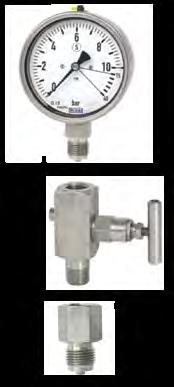
41 Pressure & Temperature Gauges 420

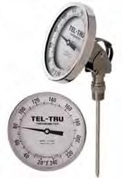
42 Pressure & Temperature Gauges 421
Hydrocarbon & Chemical Processing Solutions
 Hydrocarbon & Chemical Processing Solutions Table of Contents Armstrong Packaged Piping Solutions...3-4 Steam Distribution Manifolds (MSD/SMSD) & Cost Comparison Worksheet...5-7 Condensate Collection Assembly
Armstrong Steam System Solutions for the Hydrocarbon and Chemical Processing Industries
 Bulletin 290-B Armstrong Steam System Solutions for the Hydrocarbon and Chemical Processing Industries Packaged Piping Solutions - Steam Distribution Manifolds - Condensate Collection Assemblies - Trap
Armstrong Steam System Solutions for the Hydrocarbon and Chemical Processing Industries
 Bulletin 290-C Armstrong Steam System Solutions for the Hydrocarbon and Chemical Processing Industries Packaged Piping Solutions - Steam Distribution Manifolds - Condensate Collection Assemblies - Trap
STEAM TRAPS
 STEAM TRAPS 08.2016 info@ayvaz.com www.ayvaz.com SELECTION OF STEAM TRAPS In order to get maximum efficiency and service life from the steam lines and steam related systems, it is crucial to make the correct
STAINLESS STEEL TRAP VALVE STATION
 STAINLESS STEEL TRAP VALVE STATION MAKES A LONG STORY... 36 [914 MM]...SHORT. 4.75 [121 MM] THE INNOVATION IS INTEGRATION Armstrong stainless steel Trap Valve Station (TVS) reduces your costs for installation,
THERMOSTATIC STEAM TRAPS
 THERMOSTATIC STEAM TRAPS Nicholson is the originator of the bellows actuated Thermostatic Steam. Nicholson s thermostatic product range spans applications from critical tracing to high capacity process.
Liquid Drainers LIQUID DRAINERS
 Liquid Drainers 206 Liquid Drainers Model/Series Type Body Material PMO Sizes Connection Page No. (PSIG) WLDE Float Ductile Iron 200 1 1 /2, 2, 2 1 /2 NPT WLDES Float Cast Steel 300 2 1 /2 NPT, SW, FLG
FLOAT AND THERMOSTATIC STEAM TRAPS FLT17 (DN 1/2 to 1 ; DN15 to DN25)
") LOAT AND THERMOSTATIC STEAM TRAPS LT17 (DN 1/2 to 1 ; DN15 to DN25) DESCRIPTION LT17 float and thermostatic (integral air vent) steam traps series are designed for all types of low and high pressure steam
LOAT AND THERMOSTATIC STEAM TRAPS LT17 (DN 1/2 to 1 ; DN15 to DN25) DESCRIPTION LT17 float and thermostatic (integral air vent) steam traps series are designed for all types of low and high pressure steam
YARWAY PROCESS THERMODYNAMIC STEAM TRAPS SERIES 40/40D AND C250/260
 SERIES 40/40D AND C250/260 Designed for a variety of high pressure and high capacity applications found in utility, industrial and marine service FEATURES Designed to fail open. Designed for superheat
STEAM AND CONDENSATE PIPING AND PUMPS DESIGN AND CONSTRUCTION STANDARD
 PART 1: GENERAL 1.01 Purpose: A. This standard is intended to provide useful information to the Professional Service Provider (PSP) to establish a basis of design. The responsibility of the engineer is
LIQUIDATOR UMT-TD Series Thermodynamic
 52 LIQUIDATOR UMT-TD Series Thermodynamic Applications Steam Trap Unit Heaters Steam Tracing Drip Legs Tire Presses Laundry Equipment Plating Tanks Platen Presses Cooking Equipment Pressures To 450 PSIG
THERMODYNAMIC STEAM TRAPS
 53 STEAM TRAPS has a wide variety of Thermodynamic Steam Traps to accommodate applications through 600 psi. Most models utilize s exclusive Celtron Cartridge. The Celtron facilitates inline maintenance
Yarway Repairable Drip and Tracer Steam Traps Series 751/761, 711/721, 731/741, 500/546, 460/515/D3
 Wide range of steam traps that provide consistent performance in less than perfect conditions Features 1 1 Thermostatic Traps Repairable Pressure assisted fail-open design Freeze proof Easy to check cyclic
PT15 MATERIAL : DIMENSIONS - Nominal in inches. AVAILABLE SPARES: Disc (Packet of 5) ORDERING INFORMATION: Refer to "HOW TO ORDER" page.
 ORDERING INFORMATION: Refer to HOW TO ORDER page.") PT5 Thermodynamic Steam Traps MATERIAL : No. PART MATERIAL QTY. (Nos.). BODY ASTM A743 Gr. CA 40 0 (Seat Hardened) (Cast Equiv. AISI 420) 2. DISC CAP ASTM A743 Gr. CA 40 0 (Cast Equiv. AISI 420) 3. DISC
PT5 Thermodynamic Steam Traps MATERIAL : No. PART MATERIAL QTY. (Nos.). BODY ASTM A743 Gr. CA 40 0 (Seat Hardened) (Cast Equiv. AISI 420) 2. DISC CAP ASTM A743 Gr. CA 40 0 (Cast Equiv. AISI 420) 3. DISC
NICHOLSON STEAM TRAP THERMODYNAMIC STEAM TRAPS
 THERMODYNAMIC S has a wide variety of Thermodynamic Steam Traps to accommodate applications through 600 psi. Most models utilize s exclusive Celtron Cartridge. The Celtron facilitates inline maintenance
Mini Pump Trap. Features: n Low maintenance - No leaking seals, impeller or motor problems reducing maintenance and downtime.
 Armstrong Mini Pump Bulletin AFH-223 The Armstrong mini pump trap is the smallest non-electric solution that can move condensate or other liuids from lower to higher points and from lower to higher pressures.
CD-33/CD-33S Controlled Disc Steam Traps
 D-33/D-33S ontrolled Disc Adapts to outdoors Optional rain guard insulating cap available to prevent excessive radiant heat loss in outside applications. Extended life Three discharge port design offers
FT600 & FT601* Steam Traps Float & Thermostatic Steam Trap. Float & Thermostatic STEAM TRAPS
 STEAM TRAPS Steam Traps Steam Trap Model * Sizes 3/4, 1, 1 1 /2, 2, 3, 4 Connections NPT, SW, FLG Body Material Carbon Steel or 316SS Options Live Orifice Air Vent PMO Max. Operating Pressure 450 PSIG
THERMODYNAMIC STEAM TRAPS
 THERMODYNAMIC STEAM TRAPS Nicholson has a wide variety of Thermodynamic Steam Traps to accommodate applications through 600 psi. Most models utilize Nicholson s exclusive Celtron Cartridge. The Celtron
Condensate Pumps Jones Boulevard Limerick Airport Business Center Pottstown PA Tel:
 www.watsonmcdaniel.com 428 Jones Boulevard Limerick Airport Business Center Pottstown PA 19464 Tel: 610-495-5131 129 Return Introduction Return System Shown below is a simplified view of a steam system
STEAM - WATER MIXERS ADCAMIX MX20
 STEAM - WATER MIXERS ADCAMIX MX20 DESCRIPTION The steam/water Adcamix mixers provide cheap, instant source of low pressure hot water by using existing steam and cold water supplies. The mixer incorporates
1 of 127. Unicron Engineering ULTRASONIC TRAP TESTER UTT 100 CONDENSATE DRAIN VALVES CDV 32
 Unicron Engineering ULTRASONIC TRAP TESTER UTT 100 The UTT- Ultrasonic Trap Tester is a battery powered instrument that gives visible and audible indication of ultrasonic frequencies. It provides easy,
Series 1140 and 1141 Temperature Regulators
 Hoffman Specialty Installation & Maintenance Instructions HS-504(E) Series 1140 and 1141 Temperature Regulators! CAUTION FOLLOW ALL INSTALLATION AND OPERATING INSTRUCTIONS. TURN OFF WATER OR STEAM BEFORE
UNIVERSAL STYLE STEAM TRAPS WU450 Series
 Watson McDaniel reserves the 2010 Watson McDaniel Company UNIVERSL STYLE STEM TRPS WU450 Series Universal Connectors for Universal Steam s STEM TRPS Model WU450, WU450S, WU450SB WU450S-LR, WU450SB-LR,
S and SF Inverted Bucket Steam Traps Installation and Maintenance Instructions
 0772150/4 IM-P077-02 ST Issue 4 S and SF Inverted Bucket Steam Traps Installation and Maintenance Instructions 1. General safety information 2. General product information 3. Installation 4. Commissioning
opening trap 30 mm Space required for Space required for opening trap 30 mm MK 45-1 with flanged ends (to DIN)
") Issue Date: 4/06 GESTRA Steam Systems Thermostatic Steam Traps MK 45-, MK 45-2 PN 40, DN 5, 20, 25 (½", ¾", ") Product Range A MK 45- MK 45-2 Description Thermostatic steam trap with membrane regulator.
Issue Date: 4/06 GESTRA Steam Systems Thermostatic Steam Traps MK 45-, MK 45-2 PN 40, DN 5, 20, 25 (½", ¾", ") Product Range A MK 45- MK 45-2 Description Thermostatic steam trap with membrane regulator.
LIQUIDATOR 450 SERIES
 LIQUIDATOR 450 UMT SERIES TRAP AND UMTC CONNECTOR APPLICATIONS Unit Heaters Steam Tracing Drip Legs Tire Presses Cooking Equipment Laundry Equipment Plating Tanks Platen Presses Air Vents OPTIONS SLR -
TDS Conductivity Probe In-Line conductivity measurement
 TDS Conductivity Probe In-Line conductivity measurement (Two-pole cells with ATC Pt 100) SPS-20 DESCRIPTION The TROL SPS-20 conductivity probe is used to measure the conductivity (TDS) of the superheated
Yarway Narvik Steam Desuperheater Series 4300 TempLow
 For precise and economical control of steam temperature Features and benefits Easy installation Installation in straight, vertical or horizontal pipe. Minimal headroom is required for mounting Only standard
Series 151 and AV5. A wide range of process thermostatic steam traps is available to match almost any application need.
 A wide range of process thermostatic steam traps is available to match almost any application need. FEATURES Simple construction Easy to maintain as installed Excellent air handling capability Pressure
The right trap for the right application.
 The right trap for the right application. Whenever you re faced with a process application, it s not enough to just select any steam trap to solve your problem. Instead, remember to match your application
Hoffman Specialty General Catalog
 Hoffman Specialty General Catalog HS-900E ESP-PLUSTM For computer aided selection of Steam Trap and Regulators, please refer to the Steam Specialty Component Selectors in the Hoffman Specialty website
THERMODYNAMIC STEAM TRAP
 THERMODYNAMIC STEAM TRAP Model 041 Model 043 041 043 For the extraction of steam condensates. For use in: steam piping, irons, laundries, tanks and vessels with condensate discharge, multiple plate presses,
THE THERMOSTATIC STEAM TRAP
 THE THERMOSTATIC STEAM TRAP The purpose of any steam trap is to discharge, promptly, all condensate (as well as air and other non-condensible gases) without discharging live steam. Since steam is a vapor
GEM TRAP FITTING & MAINTENANCE INSTRUCTIONS
 GEM TRAP FITTING & MAINTENANCE INSTRUCTIONS IMPORTANT Please read these instructions before fitting any traps. The following pages describe how each type of GEM Trap should be installed. If you are unsure
TABLE OF CONTENTS STEAM TRAPS INVERTED BUCKET SERIES PAGE FLOAT AND THERMOSTATIC SERIES PAGE THERMOSTATIC THERMODISC B0 26. How to Select All 107
 TABLE OF CONTENTS FLOAT AND THERMOSTATIC SERIES PAGE How to Select All 107 C 14 H 8 I 12 X 14 Competitive Changeover 18 THERMOSTATIC 8C 22 9C 2 17C 20 Competitive Changeover 17C 24 Replacement Modules
MFP14 Automatic pumps for condensate and other industrial fluids
 MFP14 Automatic pumps for condensate and other industrial fluids Effective condensate management... an essential part of any steam plant If energy requirements are to be kept to a minimum, then efficient
YARWAY NON-REPAIRABLE DRIP AND TRACER STEAM TRAPS SERIES PB, 29, 129Y AND 29S
 SERIES PB, 29, 129Y AND 29S Economical and simplified solutions that offer quality and optimum steam trap service FEATURES 29S 29 Thermostatic traps Pressure assisted fail-open design Freeze proof Easy
13-1. Temperature Regulator
 -1 Step 0 Type/Structure/Features Please refer to this for type, structure and features of. Step 1 Selection Please look at the ID chart to choose the right products depending on the intended uses. Details
YARWAY PROCESS THERMOSTATIC STEAM TRAPS SERIES 151 AND AV5
 A wide range of process thermostatic steam traps is available to match almost any application need FEATURES Simple construction Easy to maintain as installed Excellent air handling capability Pressure
ESCO. Committed. Group of Companies. to help conserve Steam Energy
 Group of Companies Committed to help conserve Steam Energy Company Profile Group of Industries was established in 1977 as an Energy Conservation as well as Industrial Equipments manufacturing Company concentrating
MFP14 Automatic pumps. for condensate and other industrial fluids
 MFP1 Automatic pumps for condensate and other industrial fluids Effective condensate management... an essential part of any steam plant If energy requirements are to be kept to a minimum, then efficient
Air Vents AV-392. Proven Same proven, free-floating all stainless steel mechanism as used in Armstrong steam traps.
 Proven Same proven, free-floating all stainless steel mechanism as used in Armstrong steam traps. Leak-tight Positive closing, free-floating stainless steel lever ensures leak-tight closing under all conditions.
High Capacity Instantaneous Steam Fired Water Heater
 MODEL F High Capacity Instantaneous Steam Fired Water Heater Features Compact High Capacity Design Packaged System Water heater is factory assembled on an all welded steel mounting frame to save time and
Economical and simplified solutions that offer quality and optimum steam trap service.
 Economical and simplified solutions that offer quality and optimum steam trap service. It All Comes Down To Protection Regardless of the temperature and pressure characteristics of steam line drips or
Essex County College - West Essex Campus Addition And Renovations dib # / SECTION HYDRONIC PIPING SPECIALTIES PART 1- GENERAL
 Essex County College - West Essex Campus Addition And Renovations dib # 54292 / 11-14 SECTION 232116 - HYDRONIC PIPING SPECIALTIES PART 1- GENERAL 1.1 RELATED DOCUMENTS A. Drawings and general provisions
Ball Float Steam Trap with Integral Spiratec Sensor and Flanged Connections
 Page 1 of TI-P615-03 ST Issue IFT57 SG Iron ISO 9001 Ball Float Steam Trap with Integral Spiratec Sensor and Flanged Connections Cert. No. LRQ 0963008 IFT57H DN0 (horizontal shown) DN15 (vertical shown)
Technical Data CONDENSATE COMMANDER PUMP SPENCE ENGINEERING COMPANY, INC. 150 COLDENHAM ROAD, WALDEN, NY SD 9902D
 Technical Data SD 9902D SPENCE ENGINEERING COMPANY, INC. 150 COLDENHAM ROAD, WALDEN, NY 12586-2035 PRINTED IN U.S.A. SD 79902D/9803 Condensate Commander Pump Dimensions Weight Size A B C D E* F Lbs. 1"x
Float & Thermostatic Steam Traps for efficient condensate drainage of industrial process and HVAC equipment
 Float & Thermostatic Steam Traps for efficient condensate drainage of industrial process and HVAC equipment Float & Thermostatic Steam Traps from Spirax Sarco About float & thermostatic steam traps Most
Pamphlet M2404. Mechanical Pump & Pump/ Trap. GP Series GT Series
 Pamphlet M2404 Mechanical Pump & Pump/ Trap GP Series GT Series Effective Processing Improves Plant Efficiency Increased productivity and product quality, plus reduced energy consumption and water treatment
Ball Float Controlled. Thermo Dynamic(TD) Trap Safety Valve Condensate Pump Flash Vessel Moisture Separators Deaerator Head Steam Injector Sight Glass
 Trap Safety Valve Condensate Pump Flash Vessel Moisture Separators Deaerator Head Steam Injector Sight Glass") Product of Quality Best Performance Ball Float Controlled Steam Traps Auto Drain Traps Float Valve Air Vent Valves Feed Control Valve Drain Control Valve Thermo Dynamic(TD) Trap Safety Valve Condensate
Product of Quality Best Performance Ball Float Controlled Steam Traps Auto Drain Traps Float Valve Air Vent Valves Feed Control Valve Drain Control Valve Thermo Dynamic(TD) Trap Safety Valve Condensate
Pamphlet A2404. Mechanical Pump & Pump/ Trap. GP Series GT Series
 Pamphlet A2404 Mechanical Pump & Pump/ Trap GP Series GT Series Effective Processing Improves Plant Efficiency Increased productivity and product quality, plus reduced energy consumption and water treatment
Technical Data TYPE T14 & T14D TEMPERATURE PILOT SPENCE ENGINEERING COMPANY, INC. 150 COLDENHAM ROAD, WALDEN, NY SD 4511A T14 PILOT
 Technical Data SD 4511A SPENCE ENGINEERING COMPANY, INC. 150 COLDENHAM ROAD, WALDEN, NY 12586-2035 TYPE T14 & T14D TEMPERATURE PILOT PRINTED IN U.S.A. SD 4511A/9811 5 13 /16 D 4 7 /8 1 13 /16 T14 PILOT
Noiseless Heater Vacuum Relief Valve
 Noiseless Heater Vacuum Relief Valve -1 Step Type/Structure/Features Please refer to this for structure and feature of Noiseless Heater and Vacuum Relief valve. Step 1 Selection Please look at the ID chart
Pamphlet U2404. Mechanical Pump & Pump/ Trap. GP Series GT Series
 Pamphlet U2404 Mechanical Pump & Pump/ Trap GP Series GT Series Effective Processing Improves Plant Efficiency Increased productivity and product quality, plus reduced energy consumption and water treatment
Silhouette. Feedwater Heater. Boiler Feedwater
 Roth Roth Low Low Silhouette Silhouette TRAY DEAERATORS Boiler Boiler Feedwater Feedwater Heater Heater Capacities Capacities to to 50,000 50,000 lb/hr lb/hr Model RDTV-150-5-1-2 vertical tray type deaerator
Product. Add Efficiency To Your Steam Investment... Steam Traps Drain Traps Air Vents & Eliminators Accessories Piping Assemblies Replacement Kits
 Engineering Products for the Steam Industry Since 985 Product Catalog Steam Traps Drain Traps Air Vents & Eliminators Accessories Piping Assemblies Replacement Kits Add Efficiency To Your Steam Investment...
Steam Traps. . Chambered valves such as; bleeding & venting valves and steam traps. Float Valves using a free fl oat
 s s Function Level control valves control liquid levels without the necessity of an external energy input. There are two types of level controllers including:. Chambered valves such as; bleeding & venting
SECTION COMPRESSED AIR SYSTEM. A. Pipe and pipe fittings, including valves, unions and couplings.
 SECTION 15481 COMPRESSED AIR SYSTEM PART 1 - GENERAL 1.1 SECTION INCLUDES A. Pipe and pipe fittings, including valves, unions and couplings. B. Air compressor. C. After cooler. D. Refrigerated air dryer.
Technical Data. Sizes 2 in. (DN50) to 16 in. (DN400) Approvals UL and ULC Listed FM Approved
 to 16 in. (DN400) Approvals UL and ULC Listed FM Approved") Worldwide Contacts www.tyco-fire.com Model TJR Resilient-Seated Gate Valves Outside Screw and Yoke General Description TYCO Model TJR Resilient-Seated Gate Valves are used in Fire Protection Systems for
Worldwide Contacts www.tyco-fire.com Model TJR Resilient-Seated Gate Valves Outside Screw and Yoke General Description TYCO Model TJR Resilient-Seated Gate Valves are used in Fire Protection Systems for
Inverted Bucket Float & Thermostatic Radiator Traps STEAM CONTROL PRODUCTS STEAM TRAPS
 Inverted Float & Radiator Traps STEAM CONTROL PRODUCTS STEAM TRAPS ABOUT US In 1916, the company, then known as the Sterling Engineering Company, began designing and manufacturing valves, traps, strainers
Armstrong J Series Float, Thermostatic Steam Traps, Condensate Controllers & Liquid Drainers Installation and Maintenance Manual
 Armstrong J Series, Thermostatic Steam Traps, Condensate Controllers & Liquid Drainers Installation and Maintenance Manual This bulletin should be used by experienced personnel as a guide to the installation
Documento Descargado desde:
 Documento Descargado desde: WWW.VAPORISA.CL Pumping Traps Inside Advantages Mechanical condensate pumps operate with a spring-assisted float mechanism, which means the springs themselves are a major wear
STEAM VALVE SUPPLY & SYSTEM DESIGN
 TRAP SURVEYS SYSTEM AUDITS TECHNICAL SUPPORT AND MUCH MORE... STEAM VALVE SUPPLY & SYSTEM DESIGN ISIS Steam; bringing you the expertise and technical knowledge to represent, promote and service the extensive
D-8 OUTLINE SPECIFICATION FOR HTHW HEAT EXCHANGERS
 D-8 OUTLINE SPECIFICATION FOR HTHW HEAT EXCHANGERS GENERAL: This document provides performance requirements and guideline information for Heat Exchanger equipment for Colorado College only, and is not
Catalog. Self-operated Regulators Volume 2 Temperature Regulators
 Catalog Self-operated Regulators Volume 2 Temperature Regulators Self-operated Regulators Temperature Regulators Volume 2 Catalog 2012 Overview Self-operated Temperature Regulators 5 Self-operated Pressure
BOILER HOUSE PRODUCTS GMS
 GMS BOILER HOUSE PRODUCTS Contents Page 2 Introduction 3 Condensate Pumpsets 6 Blowdown Vessels 8 Boiler Feed Tanks Page 10 Chemical Dosing Pots 11 Vent Heads 11 De-Aerator Heads Introduction to Boiler
Installation and Testing of Inverted Bucket Steam Traps Manual
 Installation and Testing of Inverted Bucket Steam Traps Manual 307-EN Please read and save these instructions Armstrong IB Traps Installation Before Installing Run pipe to trap. Before installing the trap,
Inverted Bucket Steam Traps. for efficient condensate drainage of industrial and HVAC equipment
 Inverted ucket Steam Traps for efficient condensate drainage of industrial and HVC equipment Inverted ucket steam traps The proper drainage of condensate is essential to efficient steam system operation.
Bringing Energy Down to Earth
 Bringing Energy Down to Earth Say energy. Think environment. And vice versa. Any company that is energy conscious is also environmentally conscious. Less energy consumed means less waste, fewer emissions
Model: 1200 Model: 1200-G Model: 1200-N Float-Controlled Condensate Trap, PN 40
 1 Safety instructions Model: 1200 Model: 1200-G Model: 1200-N Float-Controlled Condensate Trap, PN 40 1.1 Proper use Any improper use, intervention in the design and deviation from the design data automatically
Steam Traps and Steam Specialties
 Steam Traps and Steam Specialties The new shape in steam traps... Bestobell s Delta Element A sophisticated, yet simple, design that will provide years of trouble-free service with no live steam loss.
heating liquids PENBERTHY JET PUMP TECHNICAL DATA Section 1000 Bulletin 1400 Issued 6/87 Replaces 6/85
 Section 1000 Bulletin 1400 Issued 6/87 Replaces 6/85 PENBERTHY JET PUMP TECHNICAL DATA heating liquids This technical bulleting includes general information about Penberthy Steam Jet Heaters plus specific
Model AV Alarm Valve With and Without Model RC-1 Retard Chamber European Conformity Valve Trim General Description
 Worldwide Contacts www.tyco-fire.com Model AV--00 Alarm Valve With and Without Model RC- Retard Chamber European Conformity Valve Trim General Description The TYCO Model AV--00 Alarm Valves DN, DN0, DN0,
VALVES SECTION 15100
 VALVES SECTION 15100 PART 1 GENERAL 1.1 DESCRIPTION A. The requirements of this SECTION apply to all Work of this DIVISION where applicable. The valves, materials, and methods herein are generally common
AIC Series Float & Thermostatic Steam Trap Installation and Maintenance Instructions
 AIC Series Float & Thermostatic Steam Trap Installation and Maintenance Instructions 138-EN Please read and save these instructions Contents General Safety Information... 3 Product Information...3-5 Product
FT14 Ball Float Steam Trap (Screwed)
") Page 1 of TI-S02-0 ST Issue 9 Cert. No. LRQ 096008 ISO 9001 FT14 Ball Float Steam Trap (Screwed) Description The FT14 is an SG iron bodied ball float steam trap having stainless steel working internals
Page 1 of TI-S02-0 ST Issue 9 Cert. No. LRQ 096008 ISO 9001 FT14 Ball Float Steam Trap (Screwed) Description The FT14 is an SG iron bodied ball float steam trap having stainless steel working internals
Blowdown Separator & Aftercoolers Installation, Operation, & Maintenance
 Blowdown Separator & Aftercoolers Installation, Operation, & Maintenance 750-326 04/2010 Blowdown Separator & Aftercoolers Installation, Operation, & Maintenance INSTALLATION BLOWDOWN SEPARATOR Installation
PIP PNE00004 Steam Trap Guidelines
 July 2016 Piping PIP PNE00004 Steam Trap Guidelines PURPOSE AND USE OF PROCESS INDUSTRY PRACTICES In an effort to minimize the cost of process industry facilities, this Practice has been prepared from
APT and APT14 Automatic Pump Traps. for effective condensate drainage and removal
 APT10-4.5 and Automatic Pump Traps for effective condensate drainage and removal 1 An innovative solution for effective heat User benefits Self contained compact unit. Operates with 8 in. installation
Model: 1413 Model: 1418 Float-Controlled Condensate Trap, PN 100
 1 Safety instructions Model: 1413 Model: 1418 Float-Controlled Condensate Trap, PN 100 1.1 Proper use Any improper use, intervention in the design and deviation from the design data automatically lead
C. B. Trading Corporation
 +91-8048737256 C. B. Trading Corporation http://www.cbtc.in/ C. B. Trading Corporation is an eminent distributor and trader of a wide range of s, Pipe Fittings, Forged Carbon Steel and Water & Steam Flow
Blowdown Separator & Aftercoolers
 Blowdown Separator & Aftercoolers Installation, Operation, & Maintenance Thermaflo Engineering PO Box 473639, Charlotte, NC 28247 Blowdown Separator & Aftercoolers Installation, Operation, & Maintenance
Main Steam Vents. Hoffman Specialty Regulators. How to Select Steam Vents
 Hoffman Specialty Regulators Main Steam How to Select Steam Model Radiator Convector Unit Thermostatlic Number (Angle Type) (Bottom Inlet) Heater Mains Vent (only) Remarks 1A X Adjustable Orifice 70A X
STEAM CONSERVATION GUIDELINES
 STEAM CONSERVATION GUIDELINES FOR CONDENSATE DRAINAGE Designs, materials, weights and performance ratings are approximate and subject to change without notice. Visit for up-to-date information. CG-1 Table
Steam and Condensate Technology. Solutions which are brilliant in their simplicity. combined with a first-class design & consultancy service.
 Steam and Condensate Technology Solutions which are brilliant in their simplicity combined with a first-class design & consultancy service. Steam Traps The Free Float - Principle Free Float Steam Traps
OPERATING AND MAINTENANCE MANUAL FOR PLATE HEAT EXCHANGER INDIRECT FIRED WATER HEATER. Electric Heater Company Base Model "BWXP"
 OPERATING AND MAINTENANCE MANUAL FOR PLATE HEAT EXCHANGER INDIRECT FIRED WATER HEATER Electric Heater Company Base Model "BWXP" HUBBELL ELECTRIC HEATER COMPANY P.O. BOX 288 STRATFORD, CT 06615 PHONE: (203)
TECHNICAL DATA. Wet 26a. February 22, 2009
 February 22, 2009 Wet 26a 1. DESCRIPTION The Viking Alarm Check Valve serves as a check valve by trapping pressurized water above the clapper and preventing reverse flow from sprinkler piping. The valve
Installation and Maintenance Manual Forbes Marshall Tracer Line Trap FMMST63
 Installation and Maintenance Manual Forbes Marshall Tracer Line Trap Energy Conservation Environment Process Efficiency www.forbesmarshall.com Table of Contents 1. Preface...1 2. Important Safety Notes...1
Installation, Operation and Maintenance Instructions for Thermax Semi-Storage Calorifier
 OM001 Installation, Operation and Maintenance Instructions for Thermax Semi-Storage Calorifier These operating and maintenance instructions are for standard semi-storage calorifiers (vessels fitted with
Pumps. Pressured-powered pump catalog. The more reliable and efficient way to pump condensate and other liquids.
 Liqui-Mover Pumps Pressured-powered pump catalog The more reliable and efficient way to pump condensate and other liquids. Liqui-Mover Pumps Efficiently and effectively draining condensate from steam equipment
OPERATING AND MAINTENANCE MANUAL FOR INSTANTANEOUS STEAM FIRED WATER HEATER ELECTRIC HEATER COMPANY BASE MODEL F
 OPERATING AND MAINTENANCE MANUAL FOR INSTANTANEOUS STEAM FIRED WATER HEATER ELECTRIC HEATER COMPANY BASE MODEL F Edition 2013 HUBBELL ELECTRIC HEATER COMPANY P.O. BOX 288 STRATFORD, CT 06615 PHONE: (203)
FLO-RITE-TEMP INSTANTANEOUS WATER HEATER INSTALLATION AND ADJUSTMENT INSTRUCTIONS FOR SINGLE AND DOUBLE WALL UNITS
 FLO-RITE-TEMP INSTANTANEOUS WATER HEATER INSTALLATION AND ADJUSTMENT INSTRUCTIONS FOR SINGLE AND DOUBLE WALL UNITS Bulletin No. AY-780-L This bulletin should be used by experienced personnel as a guide
Disc Type Steam Trap TSD-42
 Disc Type TSD-42 TSD-42 is disc type steam trap for high pressure (maximum pressure: 4.2 MPa). It is compact and lightweight, and can be installed horizontally or vertically. Disc Ring By-Metal Valve seat
F-P, F-L, FT-P AND FT-L SERIES 2/3 JACKETED DIRECT STEAM TILTING & STATIONARY KETTLES PARTS AND SERVICE MANUAL
 F-P, F-L, FT-P AND FT-L SERIES 2/3 JACKETED DIRECT STEAM TILTING & STATIONARY KETTLES PARTS AND SERVICE MANUAL EFFECTIVE NOVEMBER 2, 2015 Superseding All Previous Parts Lists. The Company reserves the
Section H11 BLOWDOWN SEPARATORS CONTENTS FEATURES AND BENEFITS...H11-3 PRODUCT OFFERING...H11-3 SAMPLE SPECIFICATIONS...H11-11 ILLUSTRATIONS
 Section H BLOWDOWN SEPARATORS CONTENTS FEATURES AND BENEFITS...................................................H- PRODUCT OFFERING.......................................................H- SAMPLE SPECIFICATIONS...................................................H-
Inverted bucket steam traps Type OKZ PN6/PN16
 -TERMOENERGETIKA- Inverted bucket steam traps Type OKZ PN6/PN16 We produce the inverted bucket steam traps type OKZ for nominal pressures PN 6 and PN 16 These traps have automatic air vent on the start-up.
Operating Manual. Model: Float-Controlled Condensate Trap, PN Safety instructions. 2 General description and usage
 Model: 1090 1 Safety instructions Float-Controlled Condensate Trap, PN 16 1.1 Proper use Any improper use, intervention in the design and deviation from the design data automatically lead to termination
ø D ø g ø k Max. service [barg] pressure [psig] H 1 96 L BK 45 with butt-weld ends End connections Screwed Socket-weld
![ø D ø g ø k Max. service [barg] pressure [psig] H 1 96 L BK 45 with butt-weld ends End connections Screwed Socket-weld](/thumbs/77/74825443.jpg "ø D ø g ø k Max. service [barg] pressure [psig] H 1 96 L BK 45 with butt-weld ends End connections Screwed Socket-weld") GESTRA Steam Trap RHOMBUSline BK 45 and BK 45U International patents Issue date: /00 BK 45 and BK 45U A Space required for opening trap 70 b Thermostatic steam trap with corrosion-resistant thermostatic
GESTRA Steam Trap RHOMBUSline BK 45 and BK 45U International patents Issue date: /00 BK 45 and BK 45U A Space required for opening trap 70 b Thermostatic steam trap with corrosion-resistant thermostatic
SECTION GENERAL-SERVICE COMPRESSED-AIR SYSTEMS
 PART 1 GENERAL 1.01 SECTION INCLUDES A. Pipe and Pipe Fittings. B. Air compressor. C. Air receiver and accessories. D. Aftercooler. E. Refrigerated air dryer. F. Pressure reducing station. 1.02 RELATED