TECHNICAL DOCUMENTATION OPERATION MANUAL DTR ELIS A/1.0/ /PL
|
|
|
- Denis Roberts
- 5 years ago
- Views:
Transcription


1 TECHNICAL DOCUMENTATION OPERATION MANUAL DTR ELIS A/1./ /PL
2 Table Of Contents 1. GENERAL INFORMATION TECHNICAL DATA CONSTRUCTION DIMENSIONS ACOUSTIC PRESSURE LEVEL AIR VOLUME NOMOGRAM OF AIR FLOW SPEED HEAT OUTPUT DATA ELIS A-W ELIS A-W ELIS A-W INSTALLATION RECOMMENDATION OF MONTAGE DISTANCES MOUNTING BY RODS UNDER THE CEILING MOUNTING ON THE WALLS BY THE BRACKETS BRACKETS STAGES OF INSTALATION CONTROL SYSTEMS CONTROL ELEMENTS CONNECTING GUIDE DRV CONTROL SYSTEM DRV CONTROL SYSTEM ELIS WIRING DIAGRAMS DRV CONTROL SYSTEM WIRING DIAGRAMS DRV CONTROL SYSTEM BMS CONNECTION DRV CONTROL SYSTEM SETTING BMS ADDRESS DRV CONTROL SYSTEM BMS REGISTERS DOOR CONTACT INSTALLATION GUIDELINES FOR CONNECTION WITH POWER SUPPLY GUIDELINES FOR CONNECTION WITH PIPELINE OPERATION FILTERS REPLACEMENT CLEANING AND CONSERVATION SERVICE Thank you for purchasing the ELiS curtain. This operation manual has been issued by the FLOWAIR GŁOGOWSKI I BRZEZIŃSKI SP.J. company. The manufacturer reserves the right to make revisions and changes in the operation manual at any time and without notice, and also to make changes in the device without influencing its operation This manual is an integral part of the device and it must be delivered to the user together with the device. In order to ensure correct operation of the equipment, get thoroughly acquainted with this manual and keep it for the future. The devices may only be installed and operated in conditions for which they have been designed. Any other application, inconsistent with this manual, may lead to the occurrence of accidents with dangerous consequences. Every effort must be made in order to eliminate the possibility of improper use of the device. Access of unauthorized persons to the device should be restricted, and the operating personnel should be trained. The manufacturer bears no responsibility for damage resulting from incorrect installation, improper operating, or not getting acquainted with the guidelines of the manufacturer manual. RECOMMENDATIONS AND REQUIRED SAFETY MEASURES Get acquainted with this operation manual before performing any works at the device. The device may only be installed by qualified personnel with adequate authorisations and skills. In the building where ventilation causes underpressure, air cutrain may have limited efficiency When performing works at the device, remember about your own safety. During installation, electrical connection, connection to the heating medium, start-up, repairs and maintenance of air curtains, observe the commonly recognized safety standards and regulations. 2
; max. range 3 m; ELIS A-E-1 curtain with electrical heat exchanger max.")
; max. range 3 m; ELIS A-E-2 curtain with electrical heat exchanger max.")
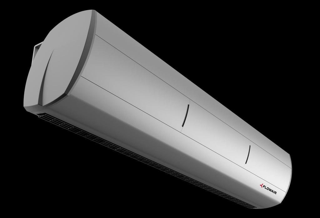
3 1. GENERAL INFORMATION Air Curtain ELiS A is dedicated to install over the door opening, it provides dynamic barrier cutting out external environment from indoor. ELIS types: ELIS A-W-1 curtain with water heat exchanger max. range 3 m; ELIS A-N-1 curtain without heat exchanger (ambient); max. range 3 m; ELIS A-E-1 curtain with electrical heat exchanger max. range 3 m; ELIS A-W-15 curtain with water heat exchanger max. range 3 m; ELIS A-N-15 curtain without heat exchanger (ambient); max. range 3 m; ELIS A-E-15 curtain with electrical heat exchanger max. range 3 m; ELIS A-W-2 curtain with water heat exchanger max. range 3 m; ELIS A-N-2 curtain without heat exchanger (ambient); max. range 3 m; ELIS A-E-2 curtain with electrical heat exchanger max. range 3 m; air inlet; curtain air outlet; 2. TECHNICAL DATA A-W- 1 A-N- 1 A-E- 1 A-W- 15 A-N- 15 A-E- 15 A-W- 2 A-N- 2 A-E- 2 Power supply [V/Hz] 23 / 5 3x4 / 5 23 / 5 3x4 / 5 23 / 5 3x4 / 5 Power consumption [kw],17 7,25 1,7,34 15 Current consumption [A],72 1 1,1 15,5 1,45 21,5 IP / Insulation class 21 / F Connecting stub [ ] ½ - ½ - ½ - Max. water temperature [ o C] Max. water pressure [MPa] - 1,6-1,6-1,6-1,6 - Temperature increase ( T) [ºC]* Weight [kg] 2,9 18,4 21,4 28,3 25,3 28,5 37,1 33,6 39 Weight of unit filled with water [kg] 22, , ,8 - - * T2-W temperature increase at inlet air 1C and heating agent temperature 9/7C / T2-E temperature increase at inlet air 1ºC 2.1. CONSTRUCTION Main construction aluminium; Fan dual inlet radial fan, blades are made of polypropylene, IP2, Heat exchanger copper-aluminium, connecting stub ½ ; electrical heaters PTC; Casing sheet steel RAL 96 or 91, side panels are made of ABS, 96 or 91 inlet grille PA6GF3,RAL 97 or 93 outlet of air curtain PA6GF3, RAL 716 or 93 Brackets steel, RAL 96 or
 56dB(A) 57dB(A) 2 46dB(A) 49dB(A) 51dB(A) 1 42dB(A) 45dB(A) 47dB(A) Acoustic pressure level")
4 2.2. DIMENSIONS ELIS: A-W-1; A-N-1; A-E-1 ELIS: A-W-15; A-N-15; A-E-15 ELIS: A-W-2; A-N-2; A-E ACOUSTIC PRESSURE LEVEL step A-W-1; A-N-1; A-E-1 A-W-15; A-N-15; A-E-15 A-W-2; A-N-2; A-E dB(A) 56dB(A) 57dB(A) 2 46dB(A) 49dB(A) 51dB(A) 1 42dB(A) 45dB(A) 47dB(A) Acoustic pressure level measured in the room of average sound absorption, capacity 5m 3, at the distance of 3 m apart of the unit AIR VOLUME step A-W-1; A-N-1; A-E-1 A-W-15; A-N-15; A-E-15 A-W-2; A-N-2; A-E m 3 /h 25 m 3 /h 35 m 3 /h 2 115m 3 /h 21 m 3 /h 29 m 3 /h 1 8m 3 /h 165 m 3 /h 24 m 3 /h 4
5 85/115/15 85/115/15 85/115/15 Air flow speed [m/s] Air flow speed [m/s] 2.5. NOMOGRAM OF AIR FLOW SPEED ELIS A-W-1; A-N-1; A-E-1 ELIS A-W-15; A-N-15; A-E-15; A-W-2; A-N-2; A-E-2 9, 8, 7, 6, 5, 4, 3, 2, 1,,,5 1 1,5 2 2,5 3 3,5 8, 7, 6, 5, 4, 3, 2, 1,,,5 1 1,5 2 2,5 3 3,5 distance [m] distance [m] step 1 step 2 step 3 3. HEAT OUTPUT DATA 3.1. ELIS A-W-1 PT Qw Δpw Tp2 PT Qw Δpw Tp2 Tp1 V kw l/h kpa C kw l/h kpa C C m 3 /h Tw1 / Tw2 = 9/7 o C Tw1 / Tw2 = 8/6 o C 14,4/17,7/21, 637/781/927 4,4/6,4/8,8 47/43/39 12,4/15,2/18, 545/668/793 3,4/5,/6,8 4/37/ ,3/16,4/19,4 588/721/857 3,8/5,5/7,6 49/45/41 11,3/13,9/16,5 497/61/724 2,9/4,2/5,7 43/39/ ,3/15,/17,9 541/663/788 3,3/4,8/6,5 51/47/44 1,3/12,6/15, 451/553/657 2,4/3,5/4,8 45/41/ ,2/13,7/16,3 494/66/721 2,8/4,/5,5 53/5/47 9,2/11,3/13,5 45/497/591 2,/2,9/4, 47/44/41 2 1,2/12,5/14,8 448/55/654 2,3/3,4/4,6 55/52/49 8,2/1,1/12, 36/442/526 1,6/2,4/3,2 49/46/44 Tw1 / Tw2 = 7/5 o C Tw1 / Tw2 = 7/4 o C 1,4/12,7/15,1 453/555/659 2,5/3,7/5, 34/31/28 8,6/1,5/12,5 249/36/363,9/1,3/1,7 28/25/23 5 9,3/11,4/13,5 47/498/592 2,1/3,/4,1 36/33/3 7,5/9,2/1,9 218/268/319,7/1,/1,4 3/28/26 1 8,3/1,1/12, 361/443/526 1,7/2,4/3,3 38/35/33 6,4/7,9/9,4 186/23/274,5/,8/1,1 31/3/ ,2/8,9/1,5 316/388/461 1,3/1,9/2,6 4/37/35 5,2/6,6/7,9 153/191/229,4/,6/,8 33/32/3 2 6,2/7,6/9,1 271/334/397 1,/1,5/2, 42/4/38 3,9/5,1/6,3 114/15/182,2/,4/,5 34/33/32 Tw1 / Tw2 = 6/4 o C Tw1 / Tw2 = 5/4 o C 8,3/1,1/12, 36/442/525 1,8/2,5/3,4 27/24/22 8,/9,8/11,6 693/85/11 5,8/8,3/11,4 26/24/21 5 7,2/8,9/1,5 315/386/459 1,4/2,/2,7 29/27/25 6,9/8,5/1,1 63/74/88 4,5/6,5/8,9 28/26/24 1 6,2/7,6/9, 269/331/394 1,/1,5/2, 31/29/27 5,9/7,3/8,6 515/633/752 3,4/4,9/6,7 3/28/ ,1/6,3/7,5 224/276/329,8/1,1/1,5 33/31/3 4,9/6,1/7,2 428/526/626 2,4/3,5/4,8 32/3/29 2 4,1/5,1/6,1 177/22/264,5/,7/1, 34/33/32 3,9/4,9/5,8 343/422/52 1,6/2,4/3,2 34/32/31 V air flow PT heating capacity Tp1 inlet air temperature Tp2 outlet air temperature Tw1 inlet water temperature Tw2 outlet water temperature Qw heating water stream Δpw water pressure 5
6 24/29/35 24/29/35 24/29/35 165/21/25 165/21/25 165/21/ ELIS A-W-15 PT Qw Δpw Tp2 PT Qw Δpw Tp2 Tp1 V kw l/h kpa C kw l/h kpa C C m 3 /h Tw1 / Tw2 = 9/7 o C Tw1 / Tw2 = 8/6 o C 17,9/2,7/22,9 791/914/111 5,3/6,9/8,3 32/29/27 15,3/17,7/19,6 672/777/861 4/5,6/6,3 27/25/ ,8/19,4/21,4 74/855/946 4,7/6,1/7,4 35/32/3 14,1/16,3/18,1 621/718/795 3,5/4,5/5,5 3/28/ ,6/18/2 688/795/881 4,1/5,3/6,5 38/35/34 13/15/16,6 569/658/728 3/3,9/4,7 33/31/ ,4/16,7/18,5 636/735/814 3,5/4,6/5,6 41/38/37 11,8/13,6/15 517/597/661 2,5/3,2/3,9 36/34/ ,2/15,3/17 584/674/748 3/3,9/4,8 43/41/4 1,6/12,2/13,5 464/532/593 2/2,7/3,2 39/37/36 Tw1 / Tw2 = 7/5 o C Tw1 / Tw2 = 7/4 o C 12,7/14,6/16,2 554/64/79 2,9/3,8/4,6 23/21/19 1,1/11,7/12,9 294/34/377,9/1,2/1,5 18/16/ ,5/13,3/14,7 52/58/643 2,4/3,2/3,8 26/24/22 8,8/1/11,4 257/299/331,7/1/1,2 21/19/18 1 1,3/11,9/13,2 45/52/576 2/2,6/3,1 28/27/26 7,6/8,8/9,8 22/256/284,6/,7/,9 23/22/ ,1/1,5/11,6 397/459/58 1,6/2,1/2,5 31/3/29 6,2/7,2/8,1 179/211/235,4/,5/,6 26/25/24 2 7,84/9,1/1 343/397/439 1,2/1,6/1,9 34/33/32 2,9/5,5/6,2 83/16/181,1/,3/,4 25/28/27 Tw1 / Tw2 = 6/4 o C Tw1 / Tw2 = 5/4 o C 1/11,5/12,8 434/52/556 1,9/2,5/3 18/16/15 1/11/12,6 857/992/199 6,8/8,9/1,7 18/16/15 5 9/1,1/11,2 381/441/489 1,5/2/2,4 21/19/18 8,7/1/11,1 754/872/967 5,4/7/8,5 21/19/18 1 7,5/8,7/9,7 328/38/421 1,2/1,5/1,8 23/22/21 7,5/8,6/9,6 649/751/832 4/5,3/6,4 23/22/ ,3/7,3/8 273/316/351,8/1,1/1,3 26/25/24 6,3/7,2/8 543/629/696 3/3,9/4,7 26/25/24 2 4,9/5,7/6,4 214/25/279,6/,7/,9 29/28/27 5/5,8/6,4 436/54/559 2/2,6/3,1 29/28/ ELIS A-W-2 PT Qw Δpw Tp2 PT Qw Δpw Tp2 Tp1 V kw l/h kpa C kw l/h kpa C C m 3 /h Tw1 / Tw2 = 9/7 o C Tw1 / Tw2 = 8/6 o C 25,7/29/32,2 1135/1271/ /14,5/18 32/29/27 22/24,7/27,6 97/186/1212 9/11,1/13,6 27/25/ /27/3 163/1191/1329 1,4/13/16 35/32/3 2,4/22,9/25,5 898/16/1122 7,8/9,7/11,8 3/28/ ,5/25,1/28 992/111/124 9,2/11,3/14 38/36/34 18,8/21/23,5 825/924/131 6,7/8,3/1,1 33/31/3 15 2,8/23,3/26 918/127/1147 7,9/9,8/12 4/38/37 17,1/19,1/21,4 751/841/939 5,7/7/8,5 36/34/ /21,4/24 844/945/154 6,8/8,4/1,3 43/42/4 15,4/17,3/19,2 677/758/845 4,7/5,8/7 39/37/36 Tw1 / Tw2 = 7/5 o C Tw1 / Tw2 = 7/4 o C 18,4/2,6/23 85/92/17 6,6/8,1/1 23/21/2 15,2/17/19,5 443/496/554 2,3/2,8/3,4 19/17/ ,8/18,8/21 733/821/916 5,6/6,9/8,4 26/24/23 13,5/15,1/16,9 394/441/492 1,8/2,3/2,8 22/2/ ,1/16,9/18,9 66/739/824 4,6/5,7/6,9 29/27/26 11,8/13,2/14,7 343/384/429 1,4/1,8/2,2 24/23/ ,4/15/16,7 586/655/731 3,7/4,6/5,6 31/3/29 1/11,2/12,5 291/326/364 1,1/1,3/1,6 27/26/ ,7/13/14,6 51/571/637 2,9/3,5/4,3 34/33/32 8,1/9,1/1,2 237/266/297,7/,9/1,1 3/29/28 Tw1 / Tw2 = 6/4 o C Tw1 / Tw2 = 5/4 o C 14,7/16,5/18,4 641/717/81 4,5/5,5/6,7 18/17/16 14,2/16/17,8 1237/1386/ ,2/18,8/23 18/16/ /14,6/16,3 568/636/79 3,6/4,5/5,4 21/2/19 12,5/14/15,7 192/1223/ ,1/14,9/18,3 2/19/ ,3/12,7/14,1 493/552/616 2,8/3,5/4,2 24/23/22 1,9/12,2/13,6 945/159/1182 9,3/11,5/14 23/22/ ,6/11/12 418/468/522 2/2,6/3,1 27/26/25 9,2/1,3/11,5 797/892/996 6,8/8,4/1,3 26/25/24 2 7,8/8,7/9,8 34/381/425 1,4/1,8/2,2 3/29/28 7,4/8,3/9,3 646/724/88 4,7/5,7/7 29/28/27 V air flow PT heating capacity Tp1 inlet air temperature Tp2 outlet air temperature Tw1 inlet water temperature Tw2 outlet water temperature Qw heating water stream Δpw water pressure 6


7 4. INSTALLATION Width of doorway must be equal or lower than width of air curtain outlet (or outlets if air curtains are installed side by side). While mounting ELiS A side by side it is important to start from right side (like is shown below), all electrical conntection should be done before installing following curtain RECOMMENDATION OF MONTAGE DISTANCES 4.2. MOUNTING BY RODS UNDER THE CEILING While mounting curtains under the ceiling, 4 rods M8 should be screwed minimum 2 mm deep. 7

* 4 x washer (M8)* 4 x nut (M8)* 4 x allen screw (M8)")
8 4.3. MOUNTING ON THE WALLS BY THE BRACKETS ELIS: A-W-1; A-N-1; A-E-1; A-W-15; A-N-15; A-E-15; A-W-2; A-N-2; A-E-2; 4.4. BRACKETS Brackets ELiS A 2 x bracket ELiS A 4 x plug (Ø1)* 4 x double threaded screw (M8)* 4 x washer (M8)* 4 x nut (M8)* 4 x allen screw (M8) * not included 8


9 4.5. STAGES OF INSTALATION Curtain Type Distance between brackets [mm] ELiS A-W-1; ELiS A-E-1; ELiS-A-N-1; 97 ELiS A-W-15; ELiS A-E-15; ELiS-A-N-15; 144 ELiS A-W-2; ELiS A-E-2; ELiS-A-N-2;


10 5. CONTROL SYSTEMS L TYPE CONTROL: Continous or Intermittent mode of operating (door contact, thermostat, switch) Connecting curtains controlling up to 5 units with one controller; Connecting to curtain room thermostat*, door contact*, valves with actuator*, speed controller*; *optional equipment 5.1. CONTROL ELEMENTS TS - 3-speed fan switch with room thermostat Temperature range:: o C Operatiing temperature range: +4 o C IP/Insulation class:: IP3 Max current: inductive 2A, resistive 4A Power supply: 23V/5Hz TA - 3-speed fan switch Operating temperature range: +4 o C IP/Insulation class: IP3 Max current: inductive 4A, resistive 6A DCm mechanical door contact Operating temperature range:: o C IP/Insulation class: IP 65 Connectors: 1xNC i 1xNO Max current: resistive 1A inductive 3A Max Power load: 3Vac or 25Vdc DCe magnetic door contact Operating temperature range:: o C IP/Insulation class: IP 64 Connectors: NC Max current:: inductive/resistive,5a Max power Load: 175Vdc Lenght of cabel: 2m Max operating contactors distance: 8mm SRQ3d ½ three-way 1/2 valve with actuator IP/Insulation class: IP2 Power supply: 2 24V 5/6Hz Max water temperature: +93 o C Max water pressure : 2,1MPa Kvs: 3,4 m 3 /h Opening time: 18 s SRQ2d ½ two-way 1/2 valve with actuator IP/Insulation class: IP2 Power supply: 2 24V 5/6Hz Max water temperature: +93 o C Max water pressure : 2,1MPa Kvs: 3, m 3 /h Opening time: 18 s 1

11 5.2 CONNECTING GUIDE While connecting ELiS A dismount left side panel and left front panel, cables protract by glands DRV CONTROL SYSTEM 5 Power supply 23V/5Hz; Connectors for thermostat and fan step switch; Door contact connector; Valve actuator connector ELIS-..-W; heaters contactor connector ELiS-..-E; MASTER-SLAVE connectors; TJACK slot for MASTER-SLAVE curtain connection; BMS system connection; Fans connectors; DRV CONTROL SYSTEM ELIS WIRING DIAGRAMS LED INDICATORS: G1, G2, G3 signalize number of fan speed operating S1, S2, S3 signalize number of set fan speed T signalize of valve set DC signalize of door contact set OPEN, CLOSE signalize valve actuator WORK signalize of software working SW3 operating mode switch (default settings) Device function BMS Address 1 selection adjustment MASTER mode SLAVE mode 2 operating operating 3 Curtain Heater (DUO) 4 ELiS-..-W/N ELiS-..-E 5 K1 Programme* K2 Programme** 6 Operating with thermostat Operating w/o thermostat *K1 programme Signal from door switch or thermostat is main signal for the device to run **K2 programme Signal from door switch is main signal for the device to run and thermostat is in charge of valve/heaters Power supply 23V/5Hz (OMY 3x1mm 2 ) Air curtain step switch with thermostat TS (OMY 5x,5mm 2 ) Door contact DCe/DCm (door closed contacts opened; door opened contacts closed) Valve with actuator SRSQ3d (OMY 3x,5mm 2 ) or SRQ (OMY 3x,5mm 2 ) A Exchanger water supply AB Valve water supply B Return pipe water supply 11
 A Exchanger water supply AB Valve water supply B Return pipe water supply 5.2.2. DRV CONTROL SYSTEM WIRING DIAGRAMS 5.")


12 Power supply 23V/5Hz (OMY 3x1mm 2 ) Door contact DCe/DCm (door closed contacts opened; door opened contact closed) Valve with actuator SRSQ3d (OMY 3x,5mm 2 ) or SRQ (OMY 3x,5mm 2 ) Q1, Q2, Q3 first, second or third curtain fan speed selection (1mm 2 jumper must be made on choosen step) A Exchanger water supply AB Valve water supply B Return pipe water supply DRV CONTROL SYSTEM WIRING DIAGRAMS DRV CONTROL SYSTEM MASTER-SLAVE COMMUNICATION In order to connect the drivers to the curtains with electric heaters use the diagrams in section (not considering single-phase power automation ). Three-phase power for electric curtains should be connected to the terminal block located on the left side of the device shown in the illustration NOTE: Switch 4 on SW3 to the position as shown in the picture (the other switches in accordance with the diagrams shown in section 5.2.1) and then restart the system switching it off for 5 seconds. Each time the device is switched off the heaters are being cooled for next 15 seconds. Electrical air curtain chaining provides control from 1 to 5 devices using one driver. Electrical air curtain chaining might be done in two ways: 1. With wire with modular straight plug 4-contact (RJ12); 2. With OMY 3x,5mm 2 wire. Connecting units among themselves ensure transfer of controlling signals. Whatever each curtain need to be supplied directly with 23V. Switch 4 on SW3 set in position: for MASTER curtain for SLAVE curtain DRV CONTROL SYSTEM BMS CONNECTION DRV driver has a possibility to be connected to integrated Building Management System (BMS). Parameters: Connection must be made using 3-poliges wire to Name Description connectors: IN-A; IN-B; GND (SIGNAL GROUND) Physical layer RS485 Protocol Baud rate Parity Data bits 8 STOP bits 1 MODBUS-RTU 384 [bps] Even 12
13 DRV CONTROL SYSTEM SETTING BMS ADDRESS There is a possibility to set 32 addresses which are set binary on SW3 switch. In order to set address must be made the following steps: 1) Turn off the power supply for driver; 2) Set the SW3 switches in position: SW3 Switch ) Set the device address with SW3 switches: Switch down Switch up B B1 B2 B3 B4 Address 4) Turn on the power supply WORK LED continuous signalization means that driver saves the address (address is saved when WORK LED turns off); 5) Turn off power supply; 6) Set the first switch on SW3 switch in upper position (remaining switches set according to curtain version and work programs): SW3 Switch ) Turn on the power supply, system is ready to run DRV CONTROL SYSTEM BMS REGISTERS Holding Register Data Inputs Register Data 13


14 5.3. DOOR CONTACT INSTALLATION Sample of door contact installation DCm In case of installation in way which is show on drawing below, connectors 21 and 22 need to be used 7. GUIDELINES FOR CONNECTION WITH PIPELINE Hinged doors Dce In case of installation in way which is show on drawing below, cable yellow and green need to be used. Other cables must be isolated. Hinged door Sliding doors The connection should be executed in a way which does not induce stresses. It is recommended to install vent valves at the highest point of the system. The system should be executed so that, in the case of a failure, it is possible to disassemble the device. For this purpose it is best to use shut-off valves just by the device. The system with the heating medium must be protected against an increase of the heating medium pressure above the permissible value (1.6 MPa). While screwing exchanger to pipeline - connecting stubs has to be hold by wrench. 6. GUIDELINES FOR CONNECTION WITH POWER SUPPLY Before connecting the power supply check the correctness of connection of the fan motor and the controllers. These connections should be executed in accordance with their technical documentation. Before connecting the power supply check whether the mains voltage is in accordance with the voltage on the device data shield. The electrical system supplying the fan motor should be additionally protected with a circuit breaker against the effects of a possible short-circuit in the system Starting the device without connecting the ground conductor is forbidden. 6. OPERATION The device is designed for operation inside buildings, at temperatures above o C. In low temperatures (below ºC) there is a danger of freezing of the medium. The manufacturer bears no responsibility for damage of the heat exchanger resulting from freezing of the medium in the exchanger. It is forbidden to place any objects on the heater or to hang any objects on the connecting stubs. The device must be inspected periodically. In the case of incorrect operation of the device it should be switched off immediately. It is forbidden to use a damaged device. The manufacturer bears no responsibility for damage resulting from the use of a damaged device. If it is necessary to clean the exchanger, be careful not to damage the aluminium lamellas. For the time of performing inspection or cleaning the device, the electrical power supply should be disconnected. In case water is drained from the device for a longer period of time, the exchanger tubes should be emptied with compressed air. 14

15 7. FILTERS REPLACEMENT Elis curtains can be equipped with EU2 filters. Filters need to be replaced periodically. Filled filters can causes in Air flow drop. Zbytnie zabrudzenie filtrów może powodować spadek wydajności wentylatora a tym samym zmniejszenie skuteczności wytwarzanej bariery powietrznej. Zabrania się montażu filtrów dla kurtyn z grzałkami elektrycznymi. W przypadku urządzenia z wymiennikiem wodnym montaż filtra EU2 skutkuje spadkiem zasięgu do 2,5 m. Replacing of filters step by step: 1. Dismount inlet grill guard (unscrew the screws). 9. SERVICE In the case of any irregularities in the device operation, please contact the manufacturer s service department. The manufacturer bears no responsibility for operating the device in a manner inconsistent with its purpose, by persons not authorized for this, and for damage resulting from this! Made in Poland Made in EU Manufacturer: FLOWAIR GŁOGOWSKI I BRZEZIŃSKI SP.J. ul. Chwaszczyńska 151E, Gdynia phone , fax.: info@flowair.pl 2. Dismount filters holders by unscrewing screws 3. Install grill guard 8. CLEANING AND CONSERVATION Periodically need to be checked exchanger condition. Exchanger filled with dirt causes in heat output and air flow drop. If cleaning of heat exchanger is needed use listed guidelines. Disconnect power supply of unit. Dismount inlet grill guard It is recommended to use pressured air to clean the exchanger, air stream need to be directed perpendicular to exchanger and moved along lamellas. It is prohibited to use water or sharp items to clean exchanger. Other installed equipment do not need be cleaned. 15
 627 57 21 e-mail: info@flowair.")
16 DEKLARACJA ZGODNOŚCI WE / Declaration of Conformity Producent / Manufacturer: FLOWAIR GŁOGOWSKI I BRZEZIŃSKI SP.J. Biuro / Office: Chwaszczyńska 151E, Gdynia tel. (58) tel./fax: (58) info@flowair.pl deklaruje, że / hereby confirms, that nazwa / device name: Kurtyna powietrzna / Air curtain modele / models: ELIS DUO, ELIS A, typ / types: ELIS A-W-1 ; ELIS A-N-1 ; ELIS A-E-1 ; ELIS A-W-15 ; ELIS A-N-15 ; ELIS A-E-15; ELIS A-W-2; ELIS A-N-2; ELIS A-E-2; ELIS A-W-1/AF ; ELIS A-W-1/L ; ELIS A-N-1/AF ; ELIS A-N-1/L ; ELIS A-E-1/AF ; ELIS A-E-1/L ; ELIS A-W-15/AF ; ELIS A-W-15/L ; ELIS A-N-15/AF ; ELIS A-N-15/L ; ELIS A-E-15/AF ; ELIS A-E-15/L ; ELIS A-W-2/AF ; ELIS A-W-2/L ; ELIS A-N-2/AF ; ELIS A-N-2/L ; ELIS A-E-2/AF ; ELIS A-E-2/L ; ELIS DUO; ELIS DUO EL; ELiS DUO-W-1; ELiS DUO-W-2; ELIS DUO-E-1 data wprowadzenia produktu do obrotu / product launch date: 214 jest zgodna z zasadniczymi wymaganiami / was produced in accordance to the following dyrektywy / directives MD 26/42/WE; dyrektywy / directives EMC 24/18/WE European Directives: oraz zharmonizowanymi z tymi dyrektywami normami / and harmonized norms, with above directives: PN-EN 624-1:21 Bezpieczeństwo maszyn - Wyposażenie elektryczne maszyn Część 1: Wymagania ogólne / Safety of machinery - Electrical equipment of machines - Part 1: General requirements PN-EN :24 + A1:25 + A2:28 + A12:28 + A13:29 + A14:21 + Ap:25 + Ap:26 Elektryczny sprzęt do użytku domowego i podobnego - Bezpieczeństwo użytkowania Część 1: Wymagania ogólne / Household and similar electrical appliances - Safety - Part 1: General requirements PN-EN :27 + A2:29 Elektryczny sprzęt do użytku domowego i podobnego - Bezpieczeństwo użytkowania Część 2-8: Wymagania szczegółowe dotyczące wentylatorów / Household and similar electrical appliances - Safety Part 2-3: Particular requirements for room heaters PN-EN 634-1:29 + Ap1:29 Maszyny elektryczne wirujące Część 1: Dane 16
 Klasyfikacja / Rotating electrical machines Part 5: Degrees of protection provided by the integral design of rotating electrical machines (IP")
17 znamionowe i parametry / Rotating electrical machines Part 1: Rating and performance PN-EN 634-5:24 + A1:29 Maszyny elektryczne wirujące Część 5: Stopnie ochrony zapewniane przez rozwiązania konstrukcyjne maszyn elektrycznych wirujących (kod IP) Klasyfikacja / Rotating electrical machines Part 5: Degrees of protection provided by the integral design of rotating electrical machines (IP code). Classification. PN-EN 634-8:27 Maszyny elektryczne wirujące Część 8: Oznaczanie wyprowadzeń i kierunek wirowania maszyn wirujących / Rotating electrical machines Part 8: Terminal markings and direction of rotation. PN-EN 634-9:29 Maszyny elektryczne wirujące Część 9: Dopuszczalne poziomy hałasu / Rotating electrical machines Part 9: Noise limits. PN-EN :28 Kompatybilność elektromagnetyczna (EMC) Część 6-1: Normy ogólne - Odporność w środowiskach: mieszkalnym, handlowym i lekko uprzemysłowionym / Electromagnetic compatibility (EMC) Part 6-1: Generic standards. Immunity for residential, commercial and light-industrial environments. PN-EN :28 + Ap1:29 + Ap2:29 Kompatybilność elektromagnetyczna (EMC) Część 6-2: Normy ogólne Odporność w środowiskach przemysłowych / Electromagnetic compatibility (EMC) - Part 6-2: Generic standards. Immunity for industrial environments. PN-EN :28 Kompatybilność elektromagnetyczna (EMC) Część 6-3: Normy ogólne Norma emisji w środowiskach: mieszkalnym, handlowym i lekko uprzemysłowionym / Electromagnetic compatibility (EMC) - Part 6-3: Generic standards - Emission standard for residential, commercial and light-industrial environments. PN-EN :28 Kompatybilność elektromagnetyczna (EMC) Część 6-4: Normy ogólne - Norma emisji w środowiskach przemysłowych / Electromagnetic compatibility (EMC) - Part 6-4: Generic standards - Emission standard for industrial environments. Gdynia, Product Manager Dunajski Maciej 17
OXeN. Ductless ventilation with heat recovery.
 OXeN Ductless ventilation with heat recovery www.flowair.com FLOWAIR System COMPLETE HEATING AND VENTILATION SOLUTIONS FLOWAIR has a complete heating and ventilation system for industrial and public buildings.
OXeN. Ductless ventilation with heat recovery.
 OXeN Ductless ventilation with heat recovery www.flowair.com We are an expert in providing complete heating and ventilation solutions for medium and big cubature buildings. Our offer consists of three
DUCTLESS VENTILATION WITH HEAT RECOVERY. OXeN ductless ventilation unit
 DUCTLESS VENTILATION WITH HEAT RECOVERY OXeN ductless ventilation unit OXeN DUCTLESS VENTILATION UNIT Simple ventilation solution OXeN ventilation unit is: the easiest way to create mechanical ventilation
AIR HEATING AND VENTILATION. Fan heaters LEO
 AIR HEATING AND VENTILATION Fan heaters LEO NEW SERIES OF LEO HEATERS Adapted to your needs For us a fan heater is not enough! That s why we have created a new series of LEO fan heaters with greater functionality
Technical documentation WATER HEATED AIR CURTAIN MODELS: REVENTON GROUP AERIS 100WN-1P REVENTON GROUP AERIS 150WN-1P REVENTON GROUP AERIS 200WN-1P
 Technical documentation WATER HEATED AIR CURTAIN MODELS: REVENTON GROUP AERIS 100WN-1P REVENTON GROUP AERIS 150WN-1P REVENTON GROUP AERIS 200WN-1P ENG TECHNICAL DOCUMENTATION Table of contents 1. INTRODUCTION
No. 1 in Europe New on offer air curtain GUARD
 No. 1 in Europe New on offer air curtain H E A T E R S A I R C U R T A I N S No. 1 in Europe SONNIGER IS AN EUROPEAN PRODUCER OF MODERN, ECOLOGICAL/ECO-FRIENDLY AND OPTIMALLY SELECTED UNITS FOR INDUSTRIAL
DPR-145 TEMPERATURE PROTECTION RELAY. DPR-145 User Manual V-2.0 ( ) PT100 INPUTS: 4 RELAY OUTPUTS: 4 RS-485 MODBUS PORT VDC SUPPLY -1-
 PT100 INPUTS: 4 RELAY OUTPUTS: 4 RS-485 MODBUS PORT VDC SUPPLY -1-") DPR-45 User Manual V-2.0 (2..206) DPR-45 TEMPERATURE PROTECTION RELAY PT00 INPUTS: 4 RELAY OUTPUTS: 4 RS-485 MODBUS PORT 9-50VDC SUPPLY DESCRIPTION DPR-45 is a precision unit designed for the temperature
DPR-45 User Manual V-2.0 (2..206) DPR-45 TEMPERATURE PROTECTION RELAY PT00 INPUTS: 4 RELAY OUTPUTS: 4 RS-485 MODBUS PORT 9-50VDC SUPPLY DESCRIPTION DPR-45 is a precision unit designed for the temperature
LINEAR HEAT DETECTION CABLE DURÁN-SAFE
 LINEAR HEAT DETECTION CABLE DURÁN-SAFE Installation & User Manual 2018 DURAN ELECTRONICA S.L. - All rights reserved www.duranelectronica.com I-manSAFECABLE-v05 TABLE OF CONTENTS Pages 1. INTRODUCTION...
TECHNICAL DOCUMENTATION DTR AIR WATER HEATERS IN STEEL CASING S SERIES
 TECHNICAL DOCUMENTATION DTR AIR WATER HEATERS IN STEEL CASING S SERIES ENG Technical documentation Table of contents 1. INTRODUCTION 1.1 PRECAUTIONS 1.2 TRANSPORT 1.3 PACKAGE CONTENT 1.4 USE AND PRINCIPLE
Technical documentation DTR AIR WATER HEATERS IN EPP CASING HC-3S SERIES
 Technical documentation DTR AIR WATER HEATERS IN EPP CASING HC-S SERIES PL TECHNICAL DOCUMENTATION Table of contents Heating coil: made of aluminum and copper. The temperature of the heating factor is
Technical documentation: S1 S2 S3 S4
 Technical documentation: S1 S2 S3 S4 1 Table of contents: 2 1. Introduction 3 1.1 Precautions 3 1.2 Transport 3 1.3 Package content 4 1.4 Use and principle of operation 4 2. Schematic diagram 4 2.1 Construction
Technical documentation DTR
 Technical documentation DTR ENG TECHNICAL DOCUMENTATION Table of contents. INTRODUCTION. PRECAUTIONS. TRANSPORT. PACKAGE CONTENT. USE AND PRINCIPLE OF OPERATION. DEVICE CONSTRUCTION, DIMENSIONS, TECHNICAL
Carisma Fly Carisma Fly-ECM. Made in. Italy. High Wall Fan Coil. Air Conditioning ENVIRONMENTAL COMFORT
 Made in Italy Air Conditioning High Wall Fan Coil -ECM QUALITY MANAGEMENT SYSTEMS ISO 9001 - Cert. n 0545/5 www.eurovent-certification.com www.certiflash.com ENVIRONMENTAL COMFORT CONTENTS Introduction
HEATING AND COOLING DEVICE AGC
 GDYNIA HEATING AND COOLING DEVICE - AGC 2013 1/8 HEATING AND COOLING DEVICE AGC SERVICE phone.: (+48 58) 783 99 50/51 Fax: (+48 58) 783 98 88 mobile: (+48) 510 098 081 E-mail: serwis@klimor.pl GDYNIA,
DIGITAL PANEL METER N20Z TYPE
 DIGITAL PANEL METER N20Z TYPE USER S MANUAL 1 Contents 1. APPLICATION and METER DESIGN... 5 2. METER SET... 5 3. BASIC REQUIREMENTS, OPERATIONAL SAFETY... 6 4. INSTALLATION... 7 5. SERVICE... 9 6. ERROR
Technical documentation
 Technical documentation AIR WATER HEATERS IN STEEL CASING S SERIES MODELS: REVENTON GROUP S1-3S REVENTON GROUP S2-3S REVENTON GROUP S3-3S REVENTON GROUP S4-3S ENG TECHNICAL DOCUMENTATION Table of contents
Miniature Infrared Temperature Sensors with Optional Touch Screen Display. PSC-SSS-PM with touch screen display (-CRT version)
") PSC-SSS-PM Series Miniature Infrared Temperature Sensors with Optional Touch Screen Display PSC-SSS-PM with touch screen display (- version) FEATURES Miniature sensing head and configurable electronics
PSC-SSS-PM Series Miniature Infrared Temperature Sensors with Optional Touch Screen Display PSC-SSS-PM with touch screen display (- version) FEATURES Miniature sensing head and configurable electronics
CWX 3 - CWX 5 CASSETTE TYPE TERMINAL UNIT. Cooling
 TECHNICAL INSTRUCTIONS CWX 3 - CWX 5 CASSETTE TYPE TERMINAL UNIT Cooling Heating CWX 3 pipes.60 3.9 pipes + electric heating.08.96 +.5 pipes.08.5 CWX 5 pipes.70 5.70 pipes + electric heating.3 5.3 +.50
TECHNICAL DOCUMENTATION DTR AIR WATER HEATERS IN STEEL CASING S SERIES
 TECHNICAL DOCUMENTATION DTR AIR WATER HEATERS IN STEEL CASING S SERIES ENG Technical documentation Table of contents. INTRODUCTION. PRECAUTIONS. TRANSPORT.3 PACKAGE CONTENT.4 USE AND PRINCIPLE OF OPERATION.
Instructions for the fan motor control system with integrated wiring terminals SILVER C
 Instructions for the fan motor control system with integrated wiring terminals SILVER C 1. General The motor control system is used for controlling the type EC, 0.41-10 kw fan motors in the SILVER C units.
AIR CURTAIN T SURFACE MOUNTED RANGE
 AIR CURTAIN T SURFACE MOUNTED RANGE INSTALLATION, OPERATION AND MAINTENANCE INSTRUCTIONS English T990009-- UK (v9) Page CONTENTS Page CONTENTS... ELECTRICAL SAFETY... SPECIFICATIONS.... INTRODUCTION...
ErP OPERATIONS MANUAL FOR СOMMERCIAL CURTAINS PROTON HEAT DOOR C2. Safety precautions Construction and dimensions Technical parameters Installation
 OPERATIONS MANUAL FOR СOMMERCIAL CURTAINS PROTON HEAT DOOR C 0506 ErP 05 Water heating Electric heating Without heating Safety precautions Construction and dimensions Technical parameters Installation
DIGITAL PANEL METER N20 type
 DIGITAL PANEL METER N20 type USER S MANUAL 1 2 Contents 1. APPLICATION AND METER DESIGN... 5 2. METER SET... 6 3. BASIC REQUIREMENTS, OPERATIONAL SAFETY... 6 4. INSTALLATION... 7 5. SERVICE... 9 6. ERROR
DMFPM-2R MULTIFUNCTIONAL
 Mounting and operating instructions Table of contents SAFETY AND PRECAUTIONS 3 PRODUCT DESCRIPTION 4 ARTICLE CODES 4 INTENDED AREA OF USE 4 TECHNICAL DATA 4 STANDARDS 4 OPERATIONAL DIAGRAMS 5 WIRING AND
Topvex SF02-SF12 Air Handling Unit
 Topvex SF02-SF12 Air Handling Unit Installation instructions Document in original language 130324 A004 GB Copyright Systemair AB All rights reserved E&OE Systemair AB reserves the rights to alter their
RS485 MODBUS Module 8AI
 Version 1.4 15/04/2013 Manufactured for Thank you for choosing our product. This manual will help you with proper support and proper operation of the device. The information contained in this manual have
Catalogue 2015 AHU N Range: VENTUS VS 10 - VS 650
 Catalogue 2015 01 VTS GROUP 1.1 VTS: Manufacturer No. 1 in the world 1.2 3 constituents of success 02 2.1 Water heaters 2.2 Product range 2.3 Technical parameters 2.4 Destratificator VR-D 03 CONTROLS
Comfort Air Curtains with in-built dynamic advertising
 Comfort Air Curtains with in-built dynamic advertising www.stavoklima.eu Li-DR Air Curtains Li-DR Contents Contents: page Introduction... 2 Air Curtains Li with in-built dynamic advertising (DR)... 3 Description
CWX 6 - CWX 8 - CWX 10 CASSETTE TYPE TERMINAL UNIT
 TECHNICAL INSTRUCTIONS CWX 6 - CWX 8 - CWX 10 CASSETTE TYPE TERMINAL UNIT Cooling Heating CWX 6 2 pipes 6.00 kw 7.70 kw CWX 8 2 pipes 8.00 kw 10.50 kw CWX 10 2 pipes 9.92 kw 13.00 kw November 2008 10 12
High wall fan coils Climmy FHW/FHW-ECM. Technical Catalogue
 High wall fan coils Climmy FHW/FHW-ECM Technical Catalogue Versions and Main components MODELS WITHOUT ELECTRIC HEATER All versions are available without valves, with 2 way valve or with 3 way valve fitted
Operating instructions Safety-monitoring module SRB 302X3. 1. About this document. Content
 8 Appendix 8.1 Wiring examples...4 8.2 Start configuration...4 8.3 Sensor configuration...4 8.4 Actuator configuration...5 Operating instructions.............pages 1 to 6 Original 9 EU Declaration of conformity
Technology for life. Unit heater LH
 Technology for life. Unit heater 1 2 Contents Contents... Page Basic unit: casing, fan, motors... 4 Basic unit: heat exchanger... 5 Performance tables 25...6-7 Performance tables 40...8-9 Performance tables
Instruction Manual WARNINGS
 Instruction Manual LARGE COMMERCIAL RECESSED AIR CURTAIN HSACR9000, 12000 & 18000 ELECTRICALLY HEATED RECESSED AIR CURTAINS WITH ENERGY SAVING CONTROLS INSTALLATION AND OPERATING MANUAL INDEX Section General
Gas heaters and convectors ROBUR
 Gas heaters and convectors ROBUR Table of Contents Robur M general characteristic...3 Robur M dimensions...3 Robur M construction...4 Robur M technical data...5 Robur M installation...6 Robur M accessories...7
CMA CONDENSING UNITS FOR OUTDOOR INSTALLATION INSTALLATION AND OPERATION MANUAL
 CMA CONDENSING UNITS FOR OUTDOOR INSTALLATION ECO-FRIENDLY REFRIGERANT GAS INSTALLATION AND OPERATION MANUAL Dear Customer, Thank you for having purchased a FERROLI product. It is the result of many years
8/S1 AIR CURTAINS SONATA, SONATA-V. v 1.0 (en)
") 8/S1 v 1.0 (en) AIR CURTAINS SONATA, SONATA-V www.klimaoprema.hr 1 TABLE OF CONTENTS Air curtain Sonata 3 Technical characteristics 3 Design characteristics 5 Installation 6 Control 6 Accessories 7 Electrical
8/S1 v 1.0 (en) AIR CURTAINS SONATA, SONATA-V www.klimaoprema.hr 1 TABLE OF CONTENTS Air curtain Sonata 3 Technical characteristics 3 Design characteristics 5 Installation 6 Control 6 Accessories 7 Electrical
F17W44_MFB_F_EN INSTALLATION INSTRUCTIONS
 F17W44_MFB_F_EN INSTALLATION INSTRUCTIONS Contents Page User instructions 3-5 General 3 Fan installation 3-4 Maintenance 3 Electrical installation 5 Troubleshooting 5 Technical description 6-8 General
Topvex SR 09, 11, Topvex TR Compact Air Handling Units
 Topvex SR 09, 11, Topvex TR 09-15 Compact Air Handling Units Installation instructions Document in original language 125593 A003 GB Copyright Systemair AB All rights reserved E&OE Systemair AB reserves
Comfort Ceiling Fan Coil System INDULVENT ec. Draught-free ambient air distribution with cooling capacity up to 2600 W
 Comfort Ceiling Fan Coil System INDULVENT ec NEW Draught-free ambient air distribution with cooling capacity up to 2600 W Low sound power levels Only electrical, cooling water and condensate connections
No. 1 in Europe New on offer air curtain GUARD
 No. 1 in Europe New on offer air curtain H E A T E R S A I R C U R T A I N S No. 1 in Europe SONNIGER IS AN EUROPEAN PRODUCER OF MODERN, ECOLOGICAL/ECO-FRIENDLY AND OPTIMALLY SELECTED UNITS FOR INDUSTRIAL
Product is subject to and complies with Regulation (UE) N.327/2011. cert. n Fan Coil Unit Cassette SkyStar Jumbo ECM. technical catalogue
 N.327/2011. cert. n Fan Coil Unit Cassette SkyStar Jumbo ECM. technical catalogue") cert. n. 0545 Product is subject to and complies with Regulation (UE) N.327/2011 Fan Coil Unit Cassette SkyStar Jumbo ECM technical catalogue SkyStar Jumbo ECM Table of contents SkyStar Jumbo ECM TABLE
cert. n. 0545 Product is subject to and complies with Regulation (UE) N.327/2011 Fan Coil Unit Cassette SkyStar Jumbo ECM technical catalogue SkyStar Jumbo ECM Table of contents SkyStar Jumbo ECM TABLE
Series VENTS VUT R WH ЕС
 AIR HANDLING UNITS WITH HEAT RECOVERY Series VENTS EH ЕС Series VENTS WH ЕС Air handling units with the air capacity up to 1500 m 3 /h in soundand heat-insulated casing with integrated electric heater.
NCU Mounting Details
 Revision Date December 4, 2013 RS-485 Modbus RTU Networking Room Thermostats with LCD for Fan Coil Units Installation and Operation Instructions Dimensions in mm Power Control Unit Display Control Unit
1.1 VTS: number 1 in the world pillars of success
 Heating Unit 01 VTS GROUP 1.1 VTS: number 1 in the world 1.2 3 pillars of success 02 2.1 water hearers Modernity Innovativeness Energy efficiency 2.2 Assembly 2.3 VR-D destratifier 2.4 Automation 03 TECHNICAL
USER MANUAL FOR EXPLOSION PROTECTED FLUORESCENT LIGHT FITTING type PSF 218
 CONTENT 1. Manufacturer 1 2. General safety informations 1 3. Purpose 2 4. Product compliance 2 5. Degree of protection and technical data 2 6. Type 3 7. Mounting and installation 3 8. Dimensions 6 9.
PROCESS & TEMPERATURE UNIVERSAL INPUT DIGITAL METERS
 PROCESS & TEMPERATURE UNIVERSAL INPUT DIGITAL METERS NOVA PD56 Series Thermocouple, RTD, & Process Inputs Universal Power Supply 1-24 VAC Up to 3 Alarm Relays Retransmitting 4-2 ma Output Input Max/Min
DX AIR CURTAIN. SensAir
 DX AIR CURTAIN SensAir Biddle and Daikin Complete climate system Since 2006 Biddle and Daikin have joined forces to provide a complete climate system for shops and public buildings. By combining Biddle
Comfortline L Series The appreciated, flexible Design Air curtain for mounting up to 4 metres
 Ambient on request Water heated (WL / WH) Electrically heated (E) Colour customization Lengths,.5, 2, 2.5 and 3 metres ISO 900 Comfortline L Series The appreciated, flexible Design Air curtain for mounting
Carisma Fly. Made in. Italy. Wall-mounted Fan Coil. Air Conditioning ENVIRONMENTAL COMFORT.
 Made in Italy Air Conditioning Wall-mounted Fan Coil QUALITY MANAGEMENT SYSTEMS ISO 9001 - Cert. n 0545/5 www.eurovent-certification.com www.certiflash.com ENVIRONMENTAL COMFORT CONTENTS Introduction Version
Instruction Manual. Alarm Unit For Low Gas Level # Read manual before use! Observe all safety information! Keep manual for future use!
 Mess-, Regel- und Überwachungsgeräte für Haustechnik, Industrie und Umweltschutz Lindenstraße 20 74363 Güglingen Telefon +49 7135-102-0 Service +49 7135-102-211 Telefax +49 7135-102-147 info@afriso.de
BHW INSTALLATION, OPERATION AND MAINTENANCE MANUAL MEDIUM STATIC PRESSURE DUCTABLE TYPE. Models:
 INSTALLATION, OPERATION AND MAINTENANCE MANUAL BHW MEDIUM STATIC PRESSURE DUCTABLE TYPE Models: 174 205 358 410 515 720 724 Cooling capacities from 3,1 to 25 KW Heating capacities from 4,5 to 55,5 KW Thank
Original instructions AR
 Original instructions SE... 8 GB... 22 NO... 27 FR... DE... 6 ES... 4 NL... 46 IT... 5 RU... 56 Dimensions and connections AR20/AR25 M8 002/52 940/450 494 449 92 20 98 042/552 42 20 AR20/25A/E 40 275 DN5
Process & TeMPerATUre UniversAl input DigiTAl MeTers
 Process & TeMPerATUre UniversAl input DigiTAl MeTers nova PD56 series Thermocouple, rtd, & Process inputs Universal Power supply 1-24 va c Up to 3 Alarm relays retransmitting 4-2 ma output input Max/Min
NGC-40 PANEL MOUNTED ADVANCED MODULAR HEAT-TRACING CONTROL SYSTEM HTC HTC3 PRODUCT OVERVIEW
 NGC-40 PANEL MOUNTED ADVANCED MODULAR HEAT-TRACING CONTROL SYSTEM Local configuration and monitoring with Raychem Touch 1500 touch screen display PRODUCT OVERVIEW The nvent RAYCHEM NGC-40 is a multipoint
Operating instructions Safety-monitoring module SRB 302X3. 1 About this document
 1 About this document Operating instructions... pages 1 to 6 Translation of the original operating instructions 1.1 Function This operating instructions manual provides all the information you need for
Use and Maintenance Manual. WPA-E-N/Ex. II 2 G c Ex e II T3. ATEX marking: Explosion proof stand fans WPA-E-N/Ex
 1 Use and Maintenance Manual Explosion proof stand fans WPA-E-N/Ex ATEX marking: II 2 G c Ex e II T3 18.10.2016 Explosion proof stand fans WPA-E-N/Ex 2 Contents: 1. Introductory Remarks... 3 2. Application...
NGC-40 PANEL MOUNTED ADVANCED MODULAR HEAT-TRACING CONTROL SYSTEM HTC HTC3
 NGC-40 PANEL MOUNTED ADVANCED MODULAR HEAT-TRACING CONTROL SYSTEM Local configuration and monitoring with Raychem Touch 1500 touch screen display PRODUCT OVERVIEW The Raychem NGC-40 is a multipoint electronic
Air curtain.
 Air curtain www.wingbyvts.com 01 VTS GROUP 1.1 VTS: Manufacturer No. 1 in the world 1.2 3 constituents of success 02 2.1 air curtains 2.2 Silence and power 2.3 Design and performance 2.4 Quality and design
Project planning (original) EN. Functional safety. Inverter i550-cabinet kw
 EN. Functional safety. Inverter i550-cabinet kw") Project planning (original) EN Functional safety Inverter i550-cabinet 0.25... 45 kw This page intentionally left blank! Contents Contents Safety instructions 4 Basic safety measures 4 Residual hazards
Project planning (original) EN Functional safety Inverter i550-cabinet 0.25... 45 kw This page intentionally left blank! Contents Contents Safety instructions 4 Basic safety measures 4 Residual hazards
OPERATION AND MONTAGE MANUAL ROOF FANS
 NO RFEC/U/2017-1 (EN) (valid since 18.08.2017) ROOF FANS RF/EC...-... / RFV/EC...-... Venture Industries Sp. z o.o. is not responsible for any damage caused by improper use of the fan and reserves the
Instructions for the fan motor control system, SILVER C
 Instructions for the fan motor control system, SILVER C 1. General The motor control system is used for controlling the type EC, 0.41-10 kw fan motors in the SILVER C units. The motor control system is
LCF Touch Modbus Datasheet Application Security Advice Caution
 LCF Touch Modbus Electronic Fan Coil Thermostat with Touch Display (Flush mounting) Datasheet Subject to technical alteration Issue date: 3.11.214 Application Modern design flush mounting fan coil room
Standard Devices. Electronic Alarm Indication Systems. ME 3011b
 Standard Devices Electronic Alarm Indication Systems ME 3011b Before connecting and powering this device, please read carefully the manual, and refer to it whenever you have any doubts. This brochure is
> ENGLISH VERSION. Instructions HERU 50 HERU / utg 2
 > ENGLISH VERSION Instructions HERU 50 HERU 75 1270100/ utg 2 EC declaration of conformity (as defined by the Machinery Directive 98/37/EEC, appendix 2A) We hereby confirm that HERU 50 and HERU 75 comply
active infrared 875 nm < 250 mw/m² motion & presence 157 in x 157 in (emitting spots**) 2 in/s to activate detection 250 ms 15-45
 2 in/s to activate detection 250 ms 15-45") Please keep for further use Designed for color printing Other use of the device is outside the permitted purpose and can not be guaranteed by the manufacturer. The manufacturer cannot be held responsible
Please keep for further use Designed for color printing Other use of the device is outside the permitted purpose and can not be guaranteed by the manufacturer. The manufacturer cannot be held responsible
GAN Electronic 750W/1000W DE EU
 GAN Electronic 750W/1000W DE EU 1. Introduction Thank you for purchasing the GAN Electronic 750 W / 1000 W DE EU. This manual describes the mounting and installing of the product and also describes how
Aerslim Fancoil unit. Technical information manual. Western Airconditioning B.V. Tel. +31 (0)
") Aerslim Fancoil unit Technical information manual Western Airconditioning B.V. Tel. +31 (0) 33 247 78 00 www.western.nl INDEX 1-INTRODUCTION... 2 2-OPERATING RANGE... 2 3-RADIANT PLATE... 2 4-CODE COMPORISION
Aerslim Fancoil unit Technical information manual Western Airconditioning B.V. Tel. +31 (0) 33 247 78 00 www.western.nl INDEX 1-INTRODUCTION... 2 2-OPERATING RANGE... 2 3-RADIANT PLATE... 2 4-CODE COMPORISION
CHH - Active Chilled Beam. Halton CHH. Active Chilled Beam
 Halton CHH Active Chilled Beam Combined cooling, heating, and supply air unit for suspended ceiling / bulkhead installation Excellent suitability for hotel guest rooms with high requirements for thermal
AIR CURTAIN HX RECESSED RANGE
 AIR CURTAIN HX RECESSED RANGE INSTALLATION, OPERATION AND MAINTENANCE INSTRUCTIONS English 990098-- Page CONTENTS CONTENTS... ELECTRICAL SAFETY... SPECIFICATIONS.... INTRODUCTION... 5. DELIVERY CONTENTS...
Bi2 4tubes * SLR 4T Fan coil radiator for heating and cooling at the same time. FEATURES. Cools, Dehumidifies, Heats and Filters
 Bi2 4tubes * SLR 4T Fan coil radiator for heating and cooling at the same time. FEATURES Cools, Dehumidifies, Heats and Filters Simultaneous Cooling + Heating Double HE Coil AC Motor Version with heating
ErP OPERATIONS MANUAL FOR AIR HEATER PROTON JET. PROTON JET Air Heater with with AirJet nozzle.
 OPERATIOS MAUAL FOR AIR HEATER PROTO JET ErP 2015 05010516 PROTO JET Air Heater with with AirJet nozzle Safety precautions Construction and dimensions Technical parameters Installation E RU www.protongroup.org
Aerosol Inlet Dryer. User s manual. Part Number: AE33-AEDN. User's manual Version 1.5 December /30
 Aerosol Inlet Dryer User s manual Part Number: AE33-AEDN User's manual Version 1.5 December 2015 1/30 Aerosol Inlet Dryer User s manual Version 1.5, December 2015 Copyright 2015 Aerosol d.o.o. Magee Scientific,
Optimal work climate with open doors. Industrial air curtains Model IndAC
 Optimal work climate with open doors Industrial air curtains Model IndAC Industrial air curtain Optimal work climate During loading and unloading the door remains open, without the indoor climate being
CENTRIFUGAL FAN IN SCROLL CASING. Helix S-Vent OPERATION MANUAL
 CENTRIFUGAL FAN IN SCROLL CASING Helix S-Vent EN OPERATION MANUAL Helix / S-Vent www.blaubergventilatoren.de CONTENTS CONTENTS 3 Introduction 3 Use 3 Delivery set 4 Technical data 10 Safety requirements
ATM Lighting sp. z o.o
 INSTALLATION AND MAINTENANCE MANUAL FOR EXPLOSIONPROOF LIGHT FITTING EXL210LED Carefully read the instructions before mounting the light fitting. ATM Lighting sp. z o.o., ul. Budowlanych 31, 80-298 Gdańsk,
Galletti IWC THE HYDRONIC CASSETTE UNIT PAR EXCELLENCE A guide to choosing Create value to design better
 www.galletti.it Galletti IWC THE HYDRONIC CASSETTE UNIT PAR EXCELLENCE A guide to choosing 2012 Create value to design better A guide to choosing The group It s 1961 and Galletti with its Jolly copper
Original operating instructions Safety switch with guard locking AC901S AC902S
 Original operating instructions Safety switch with guard locking AC901S AC902S 7390914/03 01/2017 Contents 1 Preliminary note...4 1.1 Explanation of symbols...4 2 Safety instructions...4 3 Items supplied...5
TERM-E ELECTRIC HEATING AND VENTILATION UNITS
 ELECTRIC HEATING AND VENTILATION UNITS INTENDED USE The heating units with axial fans, metal casing and electric heaters are designed to heat rooms such as: industrial halls, workshops, warehouses, commercial
KPSW CONSOLE TERMINAL UNIT
 TECHNICAL INSTRUCTIONS KPSW CONSOLE TERMINAL UNIT Cooling Heating KPSW.40 kw.75 kw KPSW.9 kw 4.07 kw KPSW 4.60 kw 5.0 kw November 008 0 7 - GB - 0 MARKING This product marked conforms to the essential
ME 3011C / Alarm Indication / Quick Reference Guide
 Tables of Contents Page Application 1 Features 1 Important Safety Information! 2 Note to this Guide 2 Further Information 2 Device Variants 2 General Functions 3 Annunciator Sequences - ISA 18.1 3 Plan
USER S MANUAL. VCU/VCUN Series CENTRIFUGAL FAN IN SCROLL CASING
 USER S MANUAL VCU/ Series CENTRIFUGAL FAN IN SCROLL CASING 2 CONTENTS Introduction Use Delivery set Designation key Technical data Safety requirements Design and operating logic Mounting and set-up Connection
QTS SELECTION TECHNICAL BOOKLET
 EN QTS SELECTION TECHNICAL BOOKLET Bi2 FAN RADIATORS AND FAN COILS Italian company established in 1956 2 Bi2 Bi2 TABLE OF CONTENTS 1 Range of system terminals... 6 1.1 Cabinet system terminals... 6 1.2
 EC Box Fan www.flaktwoods.com/oandm Safety, Installation, Operation and Maintenance Instructions CONTENTS Paragraphs Safety 1 Handling/Storage 2 Installation (Mechanical) 3 Fig. 1: Fig. 2: Tilt Mechanism
Technical documentaton DTR. Farmer
 Technical documentaton DTR Farmer ENG TECHNICAL DOCUMENTATON Table of contents. INTRODUCTION. PRECAUTIONS. TRANSPORT. PACKAGE CONTENT. USE AND PRINCIPLE OF OPERATION. DEVICE CONSTRUCTION, DIMENSIONS, TECHNICAL
Technical documentaton DTR. Farmer
 Technical documentaton DTR Farmer ENG TECHNICAL DOCUMENTATON Table of contents. INTRODUCTION. PRECAUTIONS. TRANSPORT. PACKAGE CONTENT. USE AND PRINCIPLE OF OPERATION. DEVICE CONSTRUCTION, DIMENSIONS, TECHNICAL
INSTALLATION OPERATION & MAINTENANCE INSTRUCTION HEAT RECOVERY UNITS VHR MODELS
 INSTALLATION OPERATION & MAINTENANCE INSTRUCTION HEAT RECOVERY UNITS VHR MODELS TSEK VENCO Havalandırma ve Makina San.ve Tic. A.Ş. 2004. Cad. No:5 45400 OSB Turgutlu MANISA / TURKİYE Tel: +90 (236) 332
General information. Technical data...2 General information...2. Description. Installation
 user manual Table of contents Technical data Technical data...2 General information...2 Installation...3 Navigation...3 First run...4 Main screen...6 Main menu...6 Time...7 Date...7 Calendar...7 Language...10
Application guide FLATAIR - FLCK/FLHK. Providing indoor climate comfort
 Application guide FLATAIR - FLCK/FLHK Providing indoor climate comfort MSL60E-0701 12-2006 Congratulations you have made a wise choice and we feel sure that it will meet your expectation INDEX CONTENTS
SONIC-ANEMO-MODBUS-12VDC Ultrasonic wind vane-anemometer and barometer
 -12VDC Ultrasonic wind vane-anemometer and barometer User Manual 12/01/2018 rev2.0 LCJ Capteurs ZA Le Chêne Ferré 44120 VERTOU (France) Tel : 02 40 05 08 55 http://www.lcjcapteurs.com contacts@lcjcapteurs.com
BC3250. Blowdown Controller
 Local regulations may restrict the use of this product to below the conditions quoted. In the interests of development and improvement of the product, we reserve the right to change the specification without
ModBus DE-1 INSTALLATION AND USER MANUAL
 ModBus DE-1 INSTALLATION AND USER MANUAL INTESIS Software, SL Distributed by DURAN ELECTRONICA S.L Tomás Bretón 50 28045 MADRID, España duran@duranelectronica.com www.duranelectronica.com 2 2010 DURAN
Operating Manual MS220DA
 ZIEHL industrie elektronik GmbH + Co KG Daimlerstraße 13, D 74523 Schwäbisch Hall + 49 791 504-0, info@ziehl.de, www.ziehl.de Temperature Relays and MINIKA Mains Monitoring Digital Panel Meters MINIPAN
NEW. Wall Controls. Air Conditioning Ceiling Air Conditioning Elegant. Cert. n 0545
 NEW Wall Controls Cert. n 0545 Air Conditioning Ceiling Air Conditioning Elegant CONTENTS Page Introduction 3 Main components 4 Dimension, Weight, Water content 5 Main technical figures 6 Working conditions
ErP OPERATIONS MANUAL FOR AIR HEATER PROTON ECO. PROTON ECO Three-speed AC-motor
 05010416 OPERATIOS MAUAL FOR AIR HEATER PROTO ECO ErP 2015 PROTO ECO Three-speed Safety precautions Construction and dimensions Technical parameters Installation E RU www.protongroup.org COTETS Operations
RSMFM-2R MULTIFUNCTIONAL
 MULTIFUNCTIONAL ROOM Mounting and operating instructions Table of contents SAFETY AND PRECAUTIONS 3 PRODUCT DESCRIPTION 4 ARTICLE CODES 4 INTENDED AREA OF USE 4 TECHNICAL DATA 4 STANDARDS 4 OPERATIONAL
Dual Input ph/orp Analyzer
 Instruction Sheet PN 51A-1055pH/rev.I February 2006 Model 1055 SOLU COMP II Dual Input ph/orp Analyzer Model Option 1055-22-32 For additional information, please refer to the Instruction Manuals CD shipped
INSTRUCTION MANUAL DAAB AUTOMATIC CONTROL UNIT EP104. Instruction manual version 1 for Software version 4.05
 INSTRUCTION MANUAL DAAB AUTOMATIC CONTROL UNIT EP104 Instruction manual version 1 for Software version 4.05 Revision: 9 FAAC Nordic AB BOX 125, SE-284 22 PERSTORP SWEDEN TEL. +46 435 77 95 00 FAX +46 435
OH720, OP720, HI720, HI722
 Cerberus PRO OH720, OP720, HI720, HI722 Automatic fire detectors For the automatically addressable detector bus C-NET The ideal fire detector for every application Signal processing with detection algorithms
INSTRUCTIONS. OJ-DV-Relay-Module. OJ Drives A DRIVES PROGRAMME DEDICATED TO VENTILATION SOLUTIONS. Optional module for OJ-DV motor controller
 INSTRUCTIONS OJ-DV-Relay-Module 67439B 10/16 (OSH) 016 OJ Electronics A/S Optional module for OJ-DV motor controller OJ Drives A DRIVES PROGRAMME DEDICATED TO VENTILATION SOLUTIONS Contents 1. Product
ErP OPERATIONS MANUAL FOR AIR HEATER PROTON AST. PROTON AST Air Heater with the anemostat
 05010416 OPERATIOS MAUAL FOR AIR HEATER PROTO AST ErP 2015 PROTO AST Air Heater with the anemostat Safety precautions Construction and dimensions Technical parameters Installation E RU www.protongroup.org