ALE Application Partner Program Inter-Working Report
|
|
|
- Lester Cobb
- 6 years ago
- Views:
Transcription

, or until ALE International issues a new")
1 ALE Application Partner Program Inter-Working Report Partner: ATT (Audio Text Telecom AG) Application type: Alarm server Application name: AMX Alcatel-Lucent Enterprise Platform: OmniPCX Enterprise The product and release listed have been tested with the Alcatel-Lucent Enterprise Communication Platform and the release specified hereinafter. The tests concern only the inter-working between the AAPP member s product and the Alcatel-Lucent Enterprise Communication Platform. The inter-working report is valid until the AAPP member s product issues a new major release of such product (incorporating new features or functionality), or until ALE International issues a new major release of such Alcatel- Lucent Enterprise product (incorporating new features or functionalities), whichever first occurs. ALE INTERNATIONAL MAKES NO REPRESENTATIONS, WARRANTIES OR CONDITIONS WITH RESPECT TO THE APPLICATION PARTNER PRODUCT. WITHOUT LIMITING THE GENERALITY OF THE FOREGOING, ALE INTERNATIONAL HEREBY EXPRESSLY DISCLAIMS ANY AND ALL REPRESENTATIONS, WARRANTIES OR CONDITIONS OF ANY NATURE WHATSOEVER AS TO THE AAPP MEMBER S PRODUCT INCLUDING WITHOUT LIMITATION THE IMPLIED WARRANTIES OF MERCHANTABILITY, NON INFRINGEMENT OR FITNESS FOR A PARTICULAR PURPOSE AND ALE INTERNATIONAL FURTHER SHALL HAVE NO LIABILITY TO AAPP MEMBER OR ANY OTHER PARTY ARISING FROM OR RELATED IN ANY MANNER TO THIS CERTIFICATE. PARTICULAR PURPOSE AND ALE INTERNATIONAL FURTHER SHALL HAVE NO LIABILITY TO AAPP MEMBER OR ANY OTHER PARTY ARISING FROM OR RELATED IN ANY MANNER TO THIS CERTIFICATE.
2 Certification overview Date of the certification September 2016 ALE International representative AAPP member representative Alcatel-Lucent Enterprise Communication Platform Alcatel-Lucent Enterprise Communication Platform release AAPP member application release Application Category Thierry Chevert Mahmut Sarac OmniPCX Enterprise R L b Alarm Server Respus Event monitoring & Alerting Author(s): Karthik Padmarajan Reviewer(s): Thierry Chevert, Krassimira Atanassov, Rachid Himmi Revision History Edition 1: creation of the document September 2016 Test results Passed Refused Postponed Passed with restrictions Refer to the section 6 for a summary of the test results. IWR validity extension None
3 AAPP Member Contact Information Contact name: Title: Address: Mr. Mahmut SARAC Product Manager Unterrietstrasse 2a Zip Code: 8152 City: Glattrbugg Country: Switzerland Phone: Fax: Mobile Phone: Web site: address:
4 TABLE OF CONTEN1 Introduction 6 2 VALIDITY OF THE INTERWORKING REPORT LIMITS OF THE TECHNICAL SUPPORT CASE OF ADDITIONAL THIRD PARTY APPLICATIONS APPLICATION INFORMATION TEST ENVIRONMENT PAGING & ALARMING SETUP HARDWARE CONFIGURATION SOFTWARE CONFIGURATION SUMMARY OF TEST RESULTS SUMMARY OF MAIN FUNCTIONS SUPPORTED Paging interface Alarming Interface Generic calls High availability configuration SUMMARY OF PROBLEMS SUMMARY OF LIMITATIONS NOTES, REMARKS TEST RESULT TEMPLATE PAGING - TEST RESULTS PAGING PROTOCOL OVERVIEW From the application to the OXE From the OXE to the application CONNECTIVITY AND SET-UP DEFENCE / RECOVERY DUPLICATION OF OMNIPCX ENTERPRISE LICENCE TEST (MANDATORY) PAGING ALARM SENDING TO DECT 8262/DECT 8242 /DECT PAGING ALARM SENDING ON OTHER TYPES OF SETS PAGING ALARM DELETION ALARM WHEN OUT OF RADIO COVERAGE / OUT OF SERVICE / OTHER ERRORS ALARMING, NOTIFICATION AND LOCATION SERVICES USING THE SIP TRUNK INTERFACE GENERIC SIP CALLS TESTS SIP Options SIP Authentication and Registrar SIP call set-up and call release SIP calls to various idle phones SIP call to various busy phones SIP calls to IBS-DECT sets out of radio range SIP calls to forwarded phone or Dect sets SIP calls to phone that is forwarded to voice mail SIP call to phone in immediate call forwarding to external destination SIP call to Out of Service phone Conference call with alarm server over SIP VOIP Link SIP call with Special Characters in CLI SIP ALARMING WITH 500 DECT, 8242DECT AND 8262DECT Test cases linked to Status message on 500DECT Test cases linked to Status message on 8242DECT Test cases linked to Status message on 8262DECT Test cases linked to Key events on 500DECT, 8242DECT and 8262DECT Test cases linked to Notification on 500 DECT with "Panic Red button" Test cases linked to Notification on 8242DECT... 41
5 9.2.7 Test cases linked to Notification on 8262 DECT EMBEDDED ALARMS TO 500DECT AND 8262DECT OVER SIP Test cases linked to "Man Down" or "Lost of verticality" on 500 DECT Test cases linked to "No Movement" on 500 DECT Test cases linked to "SHOCKS" detected on 500 DECT Test cases linked to "Man Down" or "Lost of verticality" on 8262DECT Test cases linked to "No Movement" on 8262DECT Test cases linked to "SHOCKS" detected on 8262DECT Test cases linked to "Pull Cord on 8262DECT TEST CASES LINKED TO IBS-DECT AND IP-DECT BASE STATION LOCALIZATION INCOMING ALARMS ON 500DECT, 8242DECT AND 8262DECT HIGH AVAILABILITY CONFIGURATIONS Spatial Redundancy Com Server OXE high availability Alarm server high availability OXE Passive Com Server Configuration TEST CASE OF COMBINED PAGING AND ALARMING APPENDIX A: AAPP MEMBER S APPLICATION DESCRIPTION AMX ALARM MANAGEMENT SERVER PLATFORMS ALARM CONTROL UNIT SWITZERLAND BASIC AMX FEATURES OPTIONAL AMX MODULES APPENDIX B: CONFIGURATION REQUIREMENTS OF THE AAPP MEMBER S APPLICATION APPENDIX C: ALCATEL-LUCENT ENTERPRISE COMMUNICATION PLATFORM: CONFIGURATION REQUIREMENTS PAGING CONFIGURATION ALARMING DESCRIPTION AND CONFIGURATION Site survey before deployment Equipment configuration PARAMETERS MANAGEMENT IN OMNIPCX ENTERPRISE COMSERVER Management of Automatic Call Routing to Main server Management of External SIP Gateway to Alarm server Management of Prefix to call alarm server Management of discriminator Linking ARS with External SIP Gw and protocol Management of External trunk group Internal SIP gateway DECT Creation /8262DECT Creation IBS-DECT MANAGEMENT OF IP-DECT CONFIGURATION OF ALARMING IN 500DECT CONFIGURATION OF ALARMING IN 8242DECT APPENDIX D: AAPP MEMBER S ESCALATION PROCESS APPENDIX E: AAPP PROGRAM ALCATEL-LUCENT APPLICATION PARTNER PROGRAM (AAPP) ENTERPRISE.ALCATEL-LUCENT.COM APPENDIX F: AAPP ESCALATION PROCESS INTRODUCTION ESCALATION IN CASE OF A VALID INTER-WORKING REPORT ESCALATION IN ALL OTHER CASES TECHNICAL SUPPORT ACCESS... 90
6 1 Introduction This document is the result of the certification tests performed between the AAPP member s application and Alcatel-Lucent Enterprise s platform. It certifies proper inter-working with the AAPP member s application. Information contained in this document is believed to be accurate and reliable at the time of printing. However, due to ongoing product improvements and revisions, ALE International cannot guarantee accuracy of printed material after the date of certification nor can it accept responsibility for errors or omissions. Updates to this document can be viewed on: the Technical Support page of the Enterprise Business Portal ( in the Application Partner Interworking Reports corner (restricted to Business Partners) the Application Partner portal ( with free access.
7 2 Validity of the InterWorking Report This InterWorking report specifies the products and releases which have been certified. This inter-working report is valid unless specified until the AAPP member issues a new major release of such product (incorporating new features or functionalities), or until ALE International issues a new major release of such Alcatel-Lucent Enterprise product (incorporating new features or functionalities), whichever first occurs. A new release is identified as following: a Major Release is any x. enumerated release. Example Product 1.0 is a major product release. a Minor Release is any x.y enumerated release. Example Product 1.1 is a minor product release The validity of the InterWorking report can be extended to upper major releases, if for example the interface didn t evolve, or to other products of the same family range. Please refer to the IWR validity extension chapter at the beginning of the report. Note: The InterWorking report becomes automatically obsolete when the mentioned product releases are end of life.
8 3 Limits of the Technical support For certified AAPP applications, Technical support will be provided within the scope of the features which have been certified in the InterWorking report. The scope is defined by the InterWorking report via the tests cases which have been performed, the conditions and the perimeter of the testing and identified limitations. All those details are documented in the IWR. The Business Partner must verify an InterWorking Report (see above Validity of the InterWorking Report) is valid and that the deployment follows all recommendations and prerequisites described in the InterWorking Report. The certification does not verify the functional achievement of the AAPP member s application as well as it does not cover load capacity checks, race conditions and generally speaking any real customer's site conditions. Any possible issue will require first to be addressed and analyzed by the AAPP member before being escalated to ALE International. Access to technical support by the Business Partner requires a valid ALE maintenance contract For details on all cases (3rd party application certified or not, request outside the scope of this IWR, etc.), please refer to Appendix F AAPP Escalation Process. 3.1 of additional Third party applications In case at a customer site an additional third party application NOT provided by ALE International is included in the solution between the certified Alcatel-Lucent Enterprise and AAPP member products such as a Session Border Controller or a firewall for example, ALE International will consider that situation as to that where no IWR exists. ALE International will handle this situation accordingly (for more details, please refer to Appendix F AAPP Escalation Process ).
9 4 Application information Application commercial name: AMX Alarm Management Server Application version: Alarm Server Respus Interface type: Paging Notification SIP Alarming, Notification and Location Services Brief application description: The Alarm Management Server (AMX) centralizes the processing of all events seized by external sources (building/process control, fire alarm, network management, nurse call, etc.) and notifies the alarm organization based on the respective scenario through different communication media like SMS, telephone call (VOIP), , SNMP traps, Paging or text messages on cordless handsets (DECT/WLAN) and smart phones by using data push notification services. More information is available in the appendix A.

10 5 Test environment 5.1 Paging & Alarming setup
11 5.2 Hardware configuration List main hardware equipments used for testing OmniPCX Entreprise: o CS (Call Server Processing Unit) o GD (Gateway driver processing Unit o PRA T2 (ISDN Access) o MIX 2/4/4 (ISDN T0, digital & analog interfaces) o UA digital and analog sets 5.3 Software configuration List main softwares used for testing Alcatel-Lucent Enterprise Communication Platform: OmniPCXEnterprise R11.2 -L b Partner Application : Alarm Server Respus
12 6 Summary of test results 6.1 Summary of main functions supported Paging interface Feature Status Comment Connect the application to OmniPCX Enterprise Defence and recovery Duplication of OmniPCX Enterprise OmniPCX Enterprise licensing (Mandatory) Sending a normal alarm without acknowledgement by the user Sending a normal alarm with acknowledgement by the user Sending an urgent alarm without acknowledgement by the user Sending an urgent alarm with acknowledgement by the user Sending a normal discrete alarm Sending an urgent discrete alarm Deletion of an alarm (stop an alarm) Management Out of Coverage, Out of Service OK OK OK OK OK OK OK OK OK OK OK OK
13 6.1.2 Alarming Interface. Test related to alarm messages sent by DECT sets to External application over the SIP Trunk link. Features IBS-Dect IP-Dect Alarm and notification calls from Dect sets Alarm Server 500DECT 8242DECT 8262DECT 500DECT 8242DECT 8262DECT Live call OK OK OK OK OK OK Status call OK OK OK OK OK OK Notification call OK OK OK OK OK OK (Emergency button) Keys event call OK OK OK OK OK OK Man down call OK NA OK OK NA OK No movement call OK NA OK OK NA OK Shock call OK NA OK OK NA OK Pull Cord call NA NA OK NA NA OK (1): The shock is too sensitive with this version of handset software and hardware PP3, it will be improved in future release and/or hardware. Tests related to alarms sent by external application to DECT sets (Display text and special ringing) IBS-Dect IP-Dect Features Incoming Alarms from Alarm Server Dect sets 500DECT 8242DECT 8262DECT 500DECT 8242DECT 8262DECT Normal alarm (B~) OK OK OK OK OK OK Urgent alarm (C~) OK OK OK OK OK OK Very urgent alarm (D~) OK OK OK OK OK OK Hands free mode alarm (E~) OK OK OK OK OK OK For all the alarms no voice could be heard. This issue was because the testing was done on VPN setup.
14 6.1.3 Generic calls These calls are generated by Alarm Server consequently to an alarm to notify OmniPCX Enterprise users in charge of managing these alarms. Features Generic SIP calls from Alarm server OXE sets Global status SIP Option Keep-Alive SIP Authentication & Registrar SIP call set-up and call release SIP calls to various le phones SIP call to various busy phones SIP calls to DECT sets out of radio range SIP calls to forwarded phone SIP calls to phone that is forwarded to voice mail SIP call to phone forwarded to external destination SIP call to Out of Service phone Multi-party Conference initiated by alarm server OK OK OK OK OK OK OK OK OK OK OK High availability configuration Features High availability Global status Spatial redundancy Com Server OXE Alarm Server High Availability Configuration Passive Com Server OXE OK NA OK
15 6.2 Summary of problems None 6.3 Summary of limitations During switch over in spatial setup there is delay of 5 to 10 seconds to connect to the standby server. But the alarming and paging functionality is working fine after the connection is established. There is no separate screen to show the type of incoming alarm that is triggered but the responses programmed are working. To differentiate the alarms we programmed different paging alarms in response to the type of incoming alarm triggered. 6.4 Notes, remarks The paging and alarming functionality has been combined by the application. The application has to programmed for the responses or alarms received from OXE. The application has a GUI interface to monitor the extensions and there is log for each extension that is added.
16 7 Test Result Template The results are presented as indicated in the example below: Test Test case 1 Action Expected result Test case 2 Action Expected result Test case 3 Action Expected result Test case 4 Action Expected result The application waits for PBX timer or phone set hangs up Relevant only if the CTI interface is a direct CSTA link No indication, no error message Test : a feature testing may comprise multiple steps depending on its complexity. Each step has to be completed successfully in order to conform to the test. Test : describes the test case with the detail of the main steps to be executed the and the expected result N/A: when checked, means the test case is not applicable in the scope of the application OK: when checked, means the test case performs as expected NOK: when checked, means the test case has failed. In that case, describe in the field Comment the reason for the failure and the reference number of the issue either on ALE International side or on AAPP member side Comment: to be filled in with any relevant comment. Mandatory in case a test has failed especially the reference number of the issue.
17 8 Paging - Test Results 8.1 Paging protocol overview From the application to the OXE The following fields and values are sent by the application to the OXE when sending an alarm: PagingRequestType ActiveAlarmCall value 0 - to send an alarm (text message) StopAlarmCall value 1 - to delete a previous alarms AskSotwarePack value 2 - to get current licenses ActiveSndCall value 3 - to send a discrete alarm (Same behavior as type 0) Paging Priority (A character in front of alarm name on display shows the type of alarm) NormalNoAck value 0 NormalAck value 1 UrgentNoAck value 2 UrgentAck value 3 NormalSndCall value 4 UrgentSndCall value From the OXE to the application In response to an alarm, the OXE sends back to the application one of below values: Paging State protocol values : Alert value 0 - the message is stored (ringing state) Process value 1 - the message is read or acknowledged OutOfCoverage value 2 - the destination is out of radio coverage OutOfservice value 4 - the destination is out of service Undefined value 5 - destination not declared as a NS device No Alert value 6 - the alarm cannot be deposit SPNoser value 7 - used for licenses validation Note: The AlertValue 0 is not sent back by OmniPCX Enterprise while receiving a discrete alarm (SndCall) normal or urgent to a compatible DECT set.
.")
18 8.2 Connectivity and set-up These tests shall verify that the different components are properly connected and can communicate together (the external application and the Alcatel-Lucent Communication Platform are connected and the interface link is operational). Test CNX101 CNX102 Application connection Connect the application using IP link checks if there are incident messages using «incvisu» command Check using the http interface of the cstamono (port 2555) that the application is connected Check that only one CSTA link is used. Notification test Application send Normal alarm without ack to check the connection. Note: To monitor the socket connection, we use the web page (rerouted to or http The Web server must be activated in the CS of OmniPCX Enterprise (as root: netadmin -m / security / Web server). We see the Paging/CSTA V1 socket with the remote IP address of the remote application server (or VPN IP address) :
19 8.3 Defence / Recovery Check the behaviour of the application in case of link failure, etc. Test DEF101 DEF102 DEF103 DEF104 IP disconnection Disconnect the IP interface between the OXE and the application server. Verify that CSTA link is broken. Application send alarm Use the application to send an alarm Expected result should be error message and try to reconnect. Connect back the IP link Reconnect the IP interface, and check if the application is connected again. Check if the application reconnect the CSTA link. Check if the previously message is sent to the OXE. IP disconnection during an alarm Place an alarm but don t acknowledge the alarm Disconnect the IP interface and wait for the application detect the reconnection Read the alarm and acknowledge it Reconnect the IP interface and verify what happens on the application side Resend an alarm to the set and verify that the global chain (set + application) behaves as expected.
20 8.4 Duplication of OmniPCX Enterprise Check how the application reacts in case of OXE switchover etc. The test system is configured with spatial redundancy (duplicate call servers on two different IP subnetworks). Spatial redundancy can be configured in two ways: Alternate Proxy method : Specify both CS MAIN addresses as primary and alternative proxy respectively. Requires that on non availability of primary proxy, secondary proxy is used. Requires ability to accept incoming calls from secondary proxy. DNS method : Do not specify a proxy address, only SIP domain. Specify the CS MAIN adresses as first and second DNS server, respectively. Requires that (at least on non availability of current proxy) a new DNS request is issued for every message. Only MAIN CS will respond. Requires ability to accept incoming calls from secondary CS when it becomes new MAIN. For each configuration, check: Can new outgoing calls be made immediately after switchover? Are existing calls maintained after switchover? Are incoming calls (from new MAIN CS) accepted immediately after switchover? Can existing call be modified (transfer, hang-up, etc.) after switchover? Check if a session that has been started before switchover is maintained after switchover, i.e. does the new MAIN CS send session updates and is this accepted by the client? Test DUP101 DUP102 DUP103 Application connects to Main CS using IP@ Spatial redundancy, using Alternate Proxy method Switchover to standby call server. Verify that the application reconnect the CSTA link Verify that SIP calls are working. Application connects to Main CS via DNS query Spatial redundancy, using DNS method Switchover to standby call server. Verify that the application reconnect the CSTA link Verify that SIP calls are working. Application connects to PCS Switchover to Passive Call Server (IP link to main/stdby call servers down) Verify that the application reconnect the CSTA link Verify that the SIP calls are still working.
21 8.5 Licence test (Mandatory) This test shall verify that the application is working using the following rules: If the Notification Server lock on the OmniPCX Enterprise is strictly less than 50, the link is broken, and the application should stop working with PBX. If the Notification Server lock on the OmniPCX Enterprise is more or equal than 50, the application runs normally. Test LIC101 Try to connect application with wrong license in OmniPCX Enterprise Set a Notification Server lock of 10 or 0 in OmniPCX Enterprise Try connect the application Verify that application receive PagingState 7 (SPNoser value) Try to send an alarm from application. Verify that the alarm is not sent to OXE.
22 8.6 Paging Alarm sending to Dect 8262/Dect 8242 /DECT 8232 These tests shall verify that the application is able to send the different types of alarms. The DECT 8232/DECT 8242 / 4068 set is used for these tests. The DECT infrastructure used for these tests is TDM IBS and IP-Dect. The Dect sets behaviors are the same for both infrastructures. Test FTS101 Normal Alarm Without Ack sent to Dect Device Send a normal alarm without ack: Priority 0 Verify that application receives the PagingState 0 (AlertValue) Verify that the alarm read corresponds to the alarm sent FTS102 FTS103 FTS104 FTS105 FTS106 Normal Alarm Without Ack sent to Dect Device Send a normal alarm with ack: Priority 1 Verify that application receives the PagingState 0 (AlertValue) Verify that the alarm is received on phone Read the alarm and acknowledge it. Verify that application receives the PagingState 1 (ProcessValue) Verify that the alarm read corresponds to the alarm sent. Urgent Alarm Without Ack sent to Dect Device Send a normal alarm without ack: Priority 2 Verify that application receives the PagingState 0 (AlertValue) Verify that the alarm read corresponds to the alarm sent. Urgent Alarm With Ack sent to Dect Device Send an urgent alarm with ack; Priority 3 Verify that application receives the PagingState 0 (AlertValue) Verify that the alarm is received on phone Read the alarm and acknowledge it. Verify that application receives the PagingState 1 (ProcessValue) Verify that the alarm read corresponds to the alarm sent. Normal SndCall alarm to Dect Device Send a normal discrete alarm: priority 4 Verify that application receives the PagingState 0 (AlertValue) Read the alarm and acknowledge it. Verify that application receives the PagingState 1 (ProcessValue) Verify that the alarm read corresponds to the alarm sent. Urgent SndCall Alarm to Dect Device Send an urgent discrete alarm: priority 5 Verify that application receives the PagingState 0 (AlertValue) Read the alarm and acknowledge it. Verify that application receives the PagingState 1 (ProcessValue) Verify that the alarm read corresponds to the alarm The Alert Value (Paging State 0) is not sent back by OmniPCX Enterprise while receiving a Discrete alarm (SndCall) normal or urgent. The AlertValue (Paging State 0) is not sent back by OmniPCX Enterprise while receiving a Discrete alarm (SndCall) normal or urgent.
23 sent. FTS107 Urgent Alarm With Ack sent to Busy Dect Device Place a call to the Dect8242 set Send an urgent alarm with ack; Priority 3 Verify that application receives the PagingState 0 (AlertValue) Verify that the alarm is received on phone (behavior to be verified) Read the alarm and acknowledge it. Verify that application receives the PagingState 1 (ProcessValue) Verify that the alarm read corresponds to the alarm sent. 8.7 Paging Alarm sending on other types of sets These tests shall verify the interoperability with other type of sets. Test FTA101 FTA101A FTA102 Urgent Alarm with Ack to Wlan8118/8128 Send a urgent alarm with ack; Priority 3 Verify that application receives the PagingState 0 (AlertValue) Verify that the alarm is received on phone Read the alarm and acknowledge it. Verify that application receives the PagingState 1 (ProcessValue) Verify that the alarm read corresponds to the alarm sent. Urgent Alarm With Ack sent to Busy Wlan8118/8128 Place a call to the WLAN 8118/8128 set Send an urgent alarm with ack; Priority 3 Verify that application receives the PagingState 0 (AlertValue) Verify that the alarm is received on phone (behavior to be verified) Read the alarm and acknowledge it. Verify that application receives the PagingState 1 (ProcessValue) Verify that the alarm read corresponds to the alarm sent. Urgent SndCall Alarm to Wlan8118/8128 Send an urgent discrete alarm: priority 5 Verify that application receives the PagingState 0 (AlertValue) Verify that the alarm is received on phone Read the alarm and acknowledge it. Verify that application receives the PagingState 1 (ProcessValue) Verify that the alarm read corresponds to the alarm sent.
24 FTA103 FTA103A FTA104 FTA105 FTA106 FTA107 Urgent Alarm with Ack to IP Touch 4068 set Send a urgent alarm with ack; Priority 3 Verify that application receives the PagingState 0 (AlertValue) Verify that the alarm is received on phone Read the alarm and acknowledge it. Verify that application receives the PagingState 1 (ProcessValue) Verify that the alarm read corresponds to the alarm sent. Urgent Alarm With Ack sent to Busy IP Touch 4068 set Place a call to the IP Touch 4068 set Send an urgent alarm with ack; Priority 3 Verify that application receives the PagingState 0 (AlertValue) Verify that the alarm is received on phone (behavior to be verified) Read the alarm and acknowledge it. Verify that application receives the PagingState 1 (ProcessValue) Verify that the alarm read corresponds to the alarm sent. Urgent SndCall Alarm to IP Touch 4068 set Send an urgent discrete alarm: priority 5 Verify that application receives the PagingState 0 (AlertValue) Verify that the alarm is received on phone Read the alarm and acknowledge it. Verify that application receives the PagingState 1 (ProcessValue) Verify that the alarm read corresponds to the alarm sent. Urgent Alarm with Ack to OT Connection for 8082 set Send a urgent alarm with ack; Priority 3 Verify that application receives the PagingState 0 (AlertValue) Verify that the alarm is received on phone Read the alarm and acknowledge it. Verify that application receives the PagingState 1 (ProcessValue) Verify that the alarm read corresponds to the alarm sent. Urgent SndCall Alarm to OT Connection for 8082 set Send an urgent discrete alarm: priority 5 Verify that application receives the PagingState 0 (AlertValue) Verify that the alarm is received on phone Read the alarm and acknowledge it. Verify that application receives the PagingState 1 (ProcessValue) Verify that the alarm read corresponds to the alarm sent. Urgent Alarm with Ack to DECT500 set (GAP+ mode) Configured in NOE mode. Specific version of the DECT 500
25 FTA108A FTA108 Send a urgent alarm with ack; Priority 3 Verify that application receives the PagingState 0 (AlertValue) Verify that the alarm is received on phone Read the alarm and acknowledge it. Verify that application receives the PagingState 1 (ProcessValue) Verify that the alarm read corresponds to the alarm sent. Urgent Alarm With Ack sent to Busy DECT500 set (GAP+ mode) Place a call to the DECT 500 set Send an urgent alarm with ack; Priority 3 Verify that application receives the PagingState 0 (AlertValue) Verify that the alarm is received on phone (behavior to be verified) Read the alarm and acknowledge it. Verify that application receives the PagingState 1 (ProcessValue) Verify that the alarm read corresponds to the alarm sent. Urgent SndCall Alarm to DECT500 set (GAP+ mode) Send an urgent discrete alarm: priority 5 Verify that application receives the PagingState 0 (AlertValue) Verify that the alarm is received on phone Read the alarm and acknowledge it. Verify that application receives the PagingState 1 (ProcessValue) Verify that the alarm read corresponds to the alarm sent. binary version for testing..
26 8.8 Paging Alarm deletion These tests shall verify that the application is able to delete alarms sent. Test DEL101 DEL102 Delete an Alarm from Application Use an existing alarm or send a new alarm with ack Delete this alarm by sending a PagingRequestType 1 (StopAlarmCall) Check it has been removed on the set. Delete an Alarm in case of multiple alarms Place several alarms with ack or without Delete one of these alarms alarm by sending a PagingRequestType 1 (StopAlarmCall) Check that this specific alarm has been removed on the set. 8.9 Alarm when Out of Radio Coverage / Out of Service / Other errors These tests shall verify the correct behaviour in specific situations like Out of Radio Coverage, Out of Service, wrong configuration, etc. Test OTH101 OTH102 OTH103 OTH104 Normal Alarm to IPTouch 4068 Out of Service Send a normal alarm to a IPT 4068 out of service Verify that application receives the PagingState 4 (OutOfServiceValue) Verify that the application displays that the phone is Out of Service Normal Alarm to DECT8242 Out of Service Send a normal alarm to Dect8242 out of service Verify that application receives the PagingState 4 (OutOfServiceValue) Verify that the application displays that the phone is Out of Service Normal Alarm to DECT8242 Out Of Coverage Send a normal alarm to Dect8242 out of coverage Verify that application receives the PagingState 2 (OutOfCoverageValue) Verify that the application displays that the phone is out of coverage Normal Alarm to DECT 500 Out of Service Send a normal alarm to Dect 500 out of service
27 Verify that application receives the PagingState 4 (OutOfServiceValue) Verify that the application displays that the phone is Out of Service OTH105 OTH106 OTH107 OTH108 OTH109 Normal Alarm to DECT 500 Out Of Coverage Send a normal alarm to Dect 500 out of coverage Verify that application receives the PagingState 2 (OutOfCoverageValue) Verify that the application displays that the phone is out of coverage Normal Alarm to WLAN 8118/8128 Out of Service Send a normal alarm to 8118/8128 out of service Verify that application receives the PagingState 4 (OutOfServiceValue) Verify that the application displays that the phone is Out of Service Normal Alarm to WLAN 8118/8128 Out Of Coverage Send a normal alarm to 8118/8128 out of coverage Verify that application receives the PagingState 2 (OutOfCoverageValue) Verify that the application displays that the phone is out of coverage Normal Alarm to phone number without NS / Paging right Send a normal alarm to a phone without Paging feature Verify that application receives the PagingState 5 (Undefined value) Verify that the application displays the error Normal alarm to phone with 8 messages already stored Send a normal alarm to a phone which alarm list is full Verify that application receives the PagingState 0 (AlertValue) Verify that the alarm is still received on phone (the oldest existing alarm is overwritten)
28 9 Alarming, Notification and Location services using the SIP trunk interface A SIP trunk is established between the OmniPCX Enterprise and Alarm Server Application (alarm server). OmniPCX Enterprise is a SIP client and Registrar in the Alarm Server application. Nota: TPA stands for Third party Application. 9.1 Generic SIP calls tests SIP Options The Option SIP message is used by the proxy or the end-point server to check the link status by keepalive messages. The OXE SIP External Gateway has a manageable timer (from 0= no Option, to 32000). Test 1 2 SIP Options from Alarm Server to OXE Alarm Server sends a SIP options request Alcatel OmniPCX Enterprise responds with a proper answer 200-OK. SIP Options from OXE to Alarm Server Alcatel OmniPCX Enterprise sends a SIP options request Alarm Server responds with a proper answer 200-OK SIP Authentication and Registrar Test SIP Trunk with authentication: - Setup Alarm Server in trunk mode with authentication - Setup Alcatel-Lucent OXE for Incoming accordingly (see Annex) - Generate a test call from Alarm Server interface. - Check that the call is accepted, that the phone rings and that a voice message is played. SIP Trunk with authentication: - Setup Alarm Server in trunk mode with authentication - Setup Alcatel-Lucent OXE for Outgoing accordingly(see Annex) - Generate an alarm from 500 DECT, - Check that the call is accepted and Alarm Server sends the 200-OK. SIP Trunk without authentication: - Setup Alarm Server in trunk mode without authentication - Setup Alcatel-Lucent OXE accordingly(see Annex) - Generate a test call from Alarm Server Web interface. - Check that the call is accepted, that the phone rings and that a voice message is played.
29 Test 4 SIP Registration from TPA - Setup Alarm Server in trunk mode with SIP registration - Setup Alcatel-Lucent OXE accordingly(see Annex) -- Check that the Register is correctly sent by TPA to OXE SIP call set-up and call release Test SIP call to phone and release from PBX - Generate a call from TPA to phone - Answer the call - Release the call after a few seconds from the phone - Check that a BYE and 200-OK are sent on the SIP signalization. SIP call to phone and release from TPA - Generate a call from TPA to a phone - Answer the call - Wait until call is released by TPA - Check that a BYE and 200-OK are sent on the SIP signalization. SIP call to phone that does no answer - Generate a call from TPA to a phone - Do not answer the call - Wait until call is released by TPA, - Check that a CANCEL and 200-OK are sent on the SIP signalization SIP calls to various idle phones Test : Hand set is in idle mode To send a call, generate a test call from the TPA Accept the call Expected result: call is accepted by PBX phone, The text message of the Alarm Server application is used as caller identifier and displayed (16 characters), On answer a voice message is played by TPA then relase of the call. Test Call to 8128 MIPT in le state Test on Alcatel-Lucent Test defined above Expected result defined above Call to 8242 DECT in idle state Test on Alcatel-Lucent 8242 DECT 2 Test defined above Expected result defined above Call to 500 DECT in idle state Test on Alcatel-Lucent 500 DECT 3 Test defined above Expected result defined above
30 Test Call to 8262 DECT in idle state Test on Alcatel-Lucent Mobile 8232 DECT 4 Test defined above Expected result defined above Call to IPTouch serie 8 in idle state Test on Alcatel-Lucent IP Touch Test defined above Expected result defined above Call to T4034 UA set in idle state Test on Alcatel-Lucent IP Touch Test defined above Expected result defined above Call to Analog Phone in idle state Test on Alcatel-Lucent Analog phone 7 Test defined above Expected result defined above Call to MyIC Phone 8082 (SIP phone) Test on Alcatel-Lucent MyIC Phone 8 Test defined above Expected result defined above Call to Generic SIP Phone Test on Generic SIP phone 9 Test defined above Expected result defined above SIP call to various busy phones Test : Phone is in communication. To send a call, generate a test call from the TPA Expected result: According to the phone configuration in Oxe, behaviors are different: call is rejected if the phone is busy: The phone is set with "Camp On" protected in "Features" options TPA logs call is rejected Test Call to busy 8128 Mobile IPTouch Test on Alcatel-Lucent 8028 Test defined above Expected result defined above Call to busy 8242 IP-DECT (AGAP over SIP) Test on Alcatel-Lucent 8242 DECT Test defined above Expected result defined above Call to busy 500 IBS-DECT (GAP) Test on Alcatel-Lucent Mobile 500 Test defined above Expected result defined above Call to busy 8232 IP-DECT Test on Alcatel-Lucent Mobile 8232 Test defined above Expected result defined above Call to busy IPTouch serie 8 - T4068 Test on Alcatel-Lucent IP Touch 4068 Test defined above
31 Test Expected result defined above Call to busy 8242 IBS-DECT Test on Alcatel-Lucent 8242 DECT Test defined above Expected result defined above Call to busy 500 IP-DECT (SIP Extension) Test on Alcatel-Lucent Mobile 500 Test defined above Expected result defined above Call to busy IPTouch 4038 Test on Alcatel-Lucent IPT4038 Test defined above Expected result defined above Call to busy Analog Phone Test on Alcatel-Lucent Analog phone Test defined above Expected result defined above Call to busy MyIC Phone 8082 Test on 8232 My Ic Phone Test defined above Expected result defined above Call to busy SIP SoftPhone Test on Generic SIP phone Test defined above Expected result defined above SIP calls to IBS-DECT sets out of radio range Test : Hand Set is in idle mode, out of range To send a call, generate a test call from the TPA Expected result: call is rejected SIP Busy Here TPA logs the call rejection reason Test was done by powering-off the Dect handsets. Test Call to 8242 DECT-IBS out of radio range Test on Alcatel-Lucent 8242 DECT Test defined above Expected result defined above Call to 8242 DECT-IP out of radio range Test on Alcatel-Lucent 8232 DECT Test defined above Expected result defined above Call to DECT8242 out of radio range Test on Alcatel-Lucent DECT 8232 Test defined above Expected result defined above Call to 500 DECT-IBS out of radio range Test on Alcatel-Lucent Mobile 500DECT Test defined above Expected result defined above
32 9.1.7 SIP calls to forwarded phone or Dect sets Test : Phone is in idle state, call forwarding is configured, To send a call, generate a test call from the TPA, Accept the call on the forwarding destination Expected result: call is forwarded to the target phone the following behavior should be the same depending on the target phone state Test Call to IPTouch serie 8 Test on Alcatel-Lucent IPTouch Serie 8 Test defined above Expected result defined above Call to IBS-500 DECT in GAP Mode Test on Alcatel-Lucent IPTouch Serie 8 Test defined above Expected result defined above Call to 8242 DECT-IP Test on Alcatel-Lucent 8242 Test defined above Expected result defined above Prefixes are: 51 for immediate forward to destination / 41 for forward cancellation SIP calls to phone that is forwarded to voice mail Test : Phone is in idle mode, immediate call forwarding to voice mail is configured To send a call, generate a test call from the TPA accept the call on the forwarding destination; which is another terminal Expected result: call forwarded to the target voice mail the following behavior should the same depending on the target phone state Test 1 Call to IPTouch 4038 forwarded to Voice Mail Test on IPTouch 4038 Test defined above Expected result defined above
33 9.1.9 SIP call to phone in immediate call forwarding to external destination Test : Phone is in idle mode, call forwarding is configured To send a call, generate a test call from the TPA accept the call on the forwarding destination; which is an external destination Expected result: call forwarded to the target voice mail the following behavior should the same depending on the target phone state Test 1 2 Call to 500 DECT forwarded to public external correspondant Test on Alcatel-Lucent 500 DECT fwd to external. Test defined above Expected result defined above Call to 4068 IPT forwarded to public external correspondant Test on Alcatel-Lucent IP Touch 4068 fwd to external. Test defined above Expected result defined above SIP call to Out of Service phone Test : Phone is out of service To send a call, generate a test call from the TPA Expected result: call is rejected TPA logs call as rejected Test 1 Call to IPTouch serie 8 Out of Service Test on Alcatel-Lucent IPTouch 4038 disconnected from system. Test defined above Expected result defined above
34 Conference call with alarm server over SIP VOIP Link This test will show that alarm server can connect multiple phones into a conference on its own. The resources for calling or be called and for connecting all users are into the Alarm server. In our configuration based on Virtual Machine, the maximum number of DSP (RTP connections) is 16 that is to say 8 conferences. Test 1 2 Alarm server call multiple correspondant to make conferencing. TPA call users that can be directly connected to conference or have to press key 3 DTMF to be connected. Alarm server maintain the conference Release of one Phone SIP call with Special Characters in CLI Test : Phone is in idle mode. To send a call, generate a test call from the TPA with text in CLI containing special accented characters. During test we sent &#$ µàéèêçüöäß as first display message then àéèêçüöäß~&#$ µ while call is answered. Check the displayed information on terminal. Expected result: The characters are displayed as they were configured in the alarm server. the following behavior should the same depending on the target phone state. Warning: The OXE country code is FR and this has been noticed that special characters from German are well displayed if country code is DE. Test Call to IPTouch 4068 (Digital NOE Extension) Alarm server sends Alarm toward the terminal. Check display of terminal. Call to MIPT 8128 (WLAN Extension) Alarm server sends Alarm toward the terminal. Check display of terminal. Call to MyIC Phone 8082 (SIP Extension) Alarm server sends Alarm toward the terminal. Check display of terminal. Call to 8242DECT Alarm server sends Alarm toward the terminal. Check display of terminal. Call to 8262DECT Alarm server sends Alarm toward the terminal. Check display of terminal.
35 9.2 SIP Alarming with 500 DECT, 8242DECT and 8262DECT Test cases linked to Live signal on 500DECT, 8242DECT and 8262DECT Live signal is executed if the appropriate function has been activated in the MMI configuration and the handset is in idle state. Alarm server 1 prefix is 85 for SIP trunking ARS / Live signal Live delay is set to 90sec. If a server 2 is configured the live signal will work alternatively with server 1 and then server2. This alternate mode was designed in the initial specifications. The alarm message is ended by 00 (digits 25 & 26) for live call state Test Live Signal on 8242DECT Put the live delay value at 90 sec. Check that two prefixes are defined (the messages are sent alternately to the first and second alternative with the defined delay between the messages) is in idle mode The! icon will blink each time an alarm is sent. Live Signal on 8262DECT Put the live delay value at 90 sec. Check that two prefixes are defined (the messages are sent alternately to the first and second alternative with the defined delay between the messages) is in idle mode The! icon will blink each time an alarm is sent. Live Signal on 500DECT Put the live delay value at 90 sec. Check that one prefix is defined in the configuration of HS. The alarm messages are sent to server with the defined delay 500 is in idle mode Display shows an outgoing call and dialled digits can be seen.
36 9.2.1 Test cases linked to Status message on 500DECT The status call is aimed to provide information about the handset when the function is active. The functions are activated in the MMI configuration menu. Test Status message on 500DECT In charger Initiate the Status function in the MMI configuration menu. A status call is made when the handset is in the charger. Check the status in the message sent by PBX Check that the notification server receives and decodes the message correctly. Status message on 500DECT Out of charger Initiate the Status function in the MMI configuration menu. A status call is made when the handset is out of charger. Check the status in the message sent by PBX Check that the notification server receives and decodes the message correctly. Status message on 500DECT switched off Step 1: Handset is out of charger Initiate the Status function in the MMI configuration menu. A status call is made when the handset is out of charger and switched-off. Check the status in the message sent by PBX Check that the notification server receives and decodes the message correctly. Step 2: Handset is in charger Initiate the Status function in the MMI configuration menu. A status call is made when the handset is in the charger and switched-off. Check the status in the message sent by PBX Check that the notification server receives and decodes the message correctly. Status message on 500DECT switched on Step 1: Handset is out of charger Initiate the Status function in the MMI configuration menu. A status call is made when the handset is out of charger and switched. Check the status in the message sent by PBX Check that the notification server receives and decodes the message correctly. Step 2: Handset is in charger Initiate the Status function in the MMI configuration menu. A status call is made when the handset is in the charger. Check the status in the message sent by PBX Check that the notification server receives and decodes the message correctly.
37 9.2.2 Test cases linked to Status message on 8242DECT The status call is aimed to provide information about the handset when the function is active. The functions are activated in the MMI configuration menu. Test Status message on 8242DECT In charger Initiate the Status function in the MMI configuration menu. A status call is made when the handset is in the charger. Check the status in the message sent by PBX Check that the notification server receives and decodes the message correctly. Status message on 8242DECT Out of charger Initiate the Status function in the MMI configuration menu. A status call is made when the handset is out of charger. Check the status in the message sent by PBX Check that the notification server receives and decodes the message correctly. Status message on 8242DECT switched off Step 1: Handset is out of charger Initiate the Status function in the MMI configuration menu. A status call is made when the handset is out of charger and switched-off. Check the status in the message sent by PBX Check that the notification server receives and decodes the message correctly. Step 2: Handset is in charger Initiate the Status function in the MMI configuration menu. A status call is made when the handset is in the charger and switched-off. Check the status in the message sent by PBX Check that the notification server receives and decodes the message correctly. Status message on 8242DECT switched on Step 1: Handset is out of charger Initiate the Status function in the MMI configuration menu. A status call is made when the handset is out of charger and switched. Check the status in the message sent by PBX Check that the notification server receives and decodes the message correctly. Step 2: Handset is in charger Initiate the Status function in the MMI configuration menu. A status call is made when the handset is in the charger. Check the status in the message sent by PBX Check that the notification server receives and decodes the message correctly.
38 9.2.3 Test cases linked to Status message on 8262DECT The status call is aimed to provide information about the handset when the function is active. The functions are activated in the MMI configuration menu. Test Status message on 8262DECT In charger Initiate the Status function in the MMI configuration menu. A status call is made when the handset is in the charger. Check the status in the message sent by PBX Check that the notification server receives and decodes the message correctly. Status message on 8262DECT Out of charger Initiate the Status function in the MMI configuration menu. A status call is made when the handset is out of charger. Check the status in the message sent by PBX Check that the notification server receives and decodes the message correctly. Status message on 8262DECT switched off Step 1: Handset is out of charger Initiate the Status function in the MMI configuration menu. A status call is made when the handset is out of charger and switched-off. Check the status in the message sent by PBX Check that the notification server receives and decodes the message correctly. Step 2: Handset is in charger Initiate the Status function in the MMI configuration menu. A status call is made when the handset is in the charger and switched-off. Check the status in the message sent by PBX Check that the notification server receives and decodes the message correctly. Status message on 8262DECT switched on Step 1: Handset is out of charger Initiate the Status function in the MMI configuration menu. A status call is made when the handset is out of charger and switched. Check the status in the message sent by PBX Check that the notification server receives and decodes the message correctly. Step 2: Handset is in charger Initiate the Status function in the MMI configuration menu. A status call is made when the handset is in the
39 Test charger. Check the status in the message sent by PBX Check that the notification server receives and decodes the message correctly Test cases linked to Key events on 500DECT, 8242DECT and 8262DECT Key events is used to signal the notification sever of the progress of tasks that are reported. For example: in an hotel to confirm that a room has been cleaned. The call type must be 2 (Key Event call). The key pressed : 8242DECT & 8262DECT: 500 DECT: Key 0: 0 Key 1: 1 Key 1: 1 Key 2: 2 Key 2: 2 Key 3: 3 Key 3: 3 Key 4: 4 Key 4: 4 Key 5: 5 Key 5: 5 Key 6: 6 Key 6: 6 Key 7: 7 Key 7: 7 Key 8: 8 Test Key events on 500DECT in le state: Initiate the Event function in the MMI configuration menu. 500DECT is in idle mode Make a long press of one of the keys from 1 to 9 to trigger the function. Check that a call is performed, display shows the dialling mode. Check that the notification server receives and decodes the message correctly Key events on 8242DECT in le state: Initiate the Event function in the MMI configuration menu. 8242DECT is in idle mode Make a long press of one of the keys from 0 to 8 to trigger the function. Check that a call is performed,! Is blinking. Check that the notification server receives and decodes the message correctly. Key events on 8262DECT in le state: Initiate the Event function in the MMI configuration menu. 8262DECT is in idle mode Make a long press of one of the keys from 0 to 8 to trigger the function. Check that a call is performed, is blinking. Check that the notification server receives and decodes the message correctly. Nota: We found that sometimes there were no decoding of the Key pressed by the application when server received multiple frames from same terminal.
40 9.2.5 Test cases linked to Notification on 500 DECT with "Panic Red button" The notification function is used to signal emergency situations by end user. Emergency situations can be injury, physical or material damage.this handset performs Notification call with a dedicated Alarm Key (Red button).the OK key is not used as the Key Events are not validated in the alarm settings. Test Notification on 500DECT in le state Activate the Notify function in the MMI configuration menu Define the first and second access prefix in the Alarm configuration. HS is in idle mode. To send a notification call make a long press on "OK" key (then next try with Side key!): Check that the notification server responds in a proper way to the handset. By sending the display message: ID followed by F ~xxxx to the handset (The handset does not display F~ but only xxx). There should be no more call to second server. Check that the notification server decodes well the message. Notification on 500DECT in communication state Activate the Notify function in the MMI configuration menu Define the first and second access prefix in the Alarm configuration. HS is engaged into a communication. To send a notification call make a long press on "OK" key (then next try with Side key!): Check that the notification server responds in a proper way to the handset. By sending the display message: ID followed by F ~xxxx to the handset (The handset does not display F~ but only xxx). There should be no more call to second server. Check that the notification server decodes well the message. Notification on 500DECT in dialling state Activate the Notify function in the MMI configuration menu Define the first and second access prefix in the Alarm configuration. HS is dialling a number. To send a notification call make a long press on "OK" key (then next try with Side key!): Check that the notification server responds in a proper way to the handset. By sending the display message: ID followed by F ~xxxx to the handset (The handset does not display F~ but only xxx). There should be no more call to second server. Check that the notification server decodes well the message. Notification on 500DECT in configuration state Activate the Notify function in the MMI configuration menu Define the first and second access prefix in the
41 Test Alarm configuration. HS is in configuration menu. To send a notification call make a long press on "OK" key (then next try with Side key!): Check that the notification server responds in a proper way to the handset. By sending the display message: ID followed by F ~xxxx to the handset (The handset does not display F~ but only xxx). There should be no more call to second server. Check that the notification server decodes well the message Test cases linked to Notification on 8242DECT The notification function is used to signal emergency situations by end user. Emergency situations can be injury, physical or material damage. This handset performs Notification call with a dedicated Alarm Key (Red button). The OK key is not used as the Key Events are not validated in the alarm settings. Test Notification on 8242DECT in le state Activate the Notify function in the MMI configuration menu Define the first and second access prefix in the Alarm configuration. HS is in idle mode. To send a notification call make a long press on "OK" key (then next try with Side key!): Check that the notification server responds in a proper way to the handset. By sending the display message: ID followed by F ~xxxx to the handset (The handset does not display F~ but only xxx). There should be no more call to second server. Check that the notification server decodes well the message. Notification on 8242DECT in communication state Activate the Notify function in the MMI configuration menu Define the first and second access prefix in the Alarm configuration. HS is engaged into a communication. To send a notification call make a long press on "OK" key (then next try with Side key!): Check that the notification server responds in a proper way to the handset. By sending the display message: ID followed by F ~xxxx to the handset (The handset does not display F~ but only xxx). There should be no more call to second server. Check that the notification server decodes well the message. Notification on 8242DECT in dialling state Activate the Notify function in the MMI configuration menu Define the first and second access prefix in the
42 Test 4 Alarm configuration. HS is dialling a number. To send a notification call make a long press on "OK" key (then next try with Side key!): Check that the notification server responds in a proper way to the handset. By sending the display message: ID followed by F ~xxxx to the handset (The handset does not display F~ but only xxx). There should be no more call to second server. Check that the notification server decodes well the message. Notification on 8242DECT in configuration state Activate the Notify function in the MMI configuration menu Define the first and second access prefix in the Alarm configuration. HS is in configuration menu. To send a notification call make a long press on "OK" key (then next try with Side key!): Check that the notification server responds in a proper way to the handset. By sending the display message: ID followed by F ~xxxx to the handset (The handset does not display F~ but only xxx). There should be no more call to second server. Check that the notification server decodes well the message.
43 9.2.7 Test cases linked to Notification on 8262 DECT The notification function is used to signal emergency situations by end user. Emergency situations can be injury, physical or material damage.this handset performs Notification call with a dedicated Alarm Key (Red button).the OK key is not used as the Key Events are not validated in the alarm settings. Test Notification on 8262DECT in le state Activate the Notify function in the MMI configuration menu Define the first and second access prefix in the Alarm configuration. HS is in idle mode. To send a notification call make a long press on "OK" key (then next try with Side key!): Check that the notification server responds in a proper way to the handset. By sending the display message: ID followed by F ~xxxx to the handset (The handset does not display F~ but only xxx). There should be no more call to second server. Check that the notification server decodes well the message. Notification on 8262DECT in communication state Activate the Notify function in the MMI configuration menu Define the first and second access prefix in the Alarm configuration. HS is engaged into a communication. To send a notification call make a long press on "OK" key (then next try with Side key!): Check that the notification server responds in a proper way to the handset. By sending the display message: ID followed by F ~xxxx to the handset (The handset does not display F~ but only xxx). There should be no more call to second server. Check that the notification server decodes well the message. Notification on 8262DECT in dialling state Activate the Notify function in the MMI configuration menu Define the first and second access prefix in the Alarm configuration. HS is dialling a number. To send a notification call make a long press on "OK" key (then next try with Side key!): Check that the notification server responds in a proper way to the handset. By sending the display message: ID followed by F ~xxxx to the handset (The handset does not display F~ but only xxx). There should be no more call to second server. Check that the notification server decodes well the message. Notification on 8262DECT in configuration state Activate the Notify function in the MMI configuration menu Define the first and second access prefix in the
44 Test Alarm configuration. HS is in configuration menu. To send a notification call make a long press on "OK" key (then next try with Side key!): Check that the notification server responds in a proper way to the handset. By sending the display message: ID followed by F ~xxxx to the handset (The handset does not display F~ but only xxx). There should be no more call to second server. Check that the notification server decodes well the message.
45 9.3 Embedded Alarms to 500DECT and 8262DECT over SIP Test cases linked to "Man Down" or "Lost of verticality" on 500 DECT The notification function is used to signal emergency situations by end user. Emergency situations can be injury, physical or material damage. This handset performs Notification call with a lost of verticality (Man Down) according 500DECT MMI configuration and timers. Test ManDown on 500DECT while in le state Configure "Man Down" function via MMI to 60 degree. Check that the Lock/Unlock is inactive. HS is in idle mode. Move the handset to horizontal position. Alarm is activated after pre-alarm timer. Check that the notification server responds in a proper way to the handset. By sending the display message: ID followed by F ~xxx to the handset (The handset does not display F~ but only xxx). Check that the notification server decodes well the message. Handset rings and need to acknowledge the alarm. While acknowledged, check that message is sent to server. ManDown on 500DECT while in Communication state Configure "Man Down" function via MMI to 60 degree. Check that the Lock/Unlock is inactive. HS is in a communication with other correspondant. Move the handset to horizontal position. Alarm is activated after pre-alarm timer. Check that the notification server responds in a proper way to the handset. By sending the display message: ID followed by F ~xxx to the handset (The handset does not display F~ but only xxx). Check that the notification server decodes well the message. Handset rings and need to acknowledge the alarm. While acknowledged, check that message is sent to server. ManDown on 500DECT while in dialling state Configure "Man Down" function via MMI to 60 degree. Check that the Lock/Unlock is inactive. HS is dialling a phone number. Move the handset to horizontal position. Alarm is activated after pre-alarm timer. Check that the notification server responds in a proper way to the handset. By sending the display message: ID followed by F ~xxx to the handset (The handset does not display F~ but only xxx). Check that the notification server decodes well the message. Not triggered while in conversation
46 Test 4 Handset rings and need to acknowledge the alarm. While acknowledged, check that message is sent to server. ManDown on 500DECT while in configuration state Configure "Man Down" function via MMI to 60 degree. Check that the Lock/Unlock is inactive. HS is in configuration mode. Move the handset to horizontal position. Alarm is activated after pre-alarm timer. Check that the notification server responds in a proper way to the handset. By sending the display message: ID followed by F ~xxx to the handset (The handset does not display F~ but only xxx). Check that the notification server decodes well the message. Handset rings and need to acknowledge the alarm. While acknowledged, check that message is sent to server. Exceptions: Man Down and no movement should be inactive when the handset is charging in or out of charger (UBS cord charger for example), or when user is browsing in Handset screens (not in idle state) or when the user is engaged in a call Test cases linked to "No Movement" on 500 DECT The notification function is used to signal emergency situations by end user. Emergency situations can be injury, physical or material damage. This handset performs Notification call with a "No Movement detection". The function and a timer is programmable in the set 500DECT; when no movement has been detected, the rings with specific rings (timer set to 10 secondes), then alarm is send to the server. Test 1 2 No Movement on 500DECT in le state Configure "No Movement" function via MMI. Check that the Lock/Unlock is inactive. HS is in idle state. Do not move the handset for a time. Alarm is activated after pre-alarm timer. Check that the notification server responds in a proper way to the handset. By sending the display message: ID followed by F ~xxx to the handset (The handset does not display F~ but only xxx). Check that the notification server decodes well the message. Handset rings and need to acknowledge the alarm. While acknowledged, check that message is sent to server. No Movement on 500DECT in communication state Configure "No Movement" function via MMI. Check that the Lock/Unlock is inactive. HS is in idle state. Do not move the handset for a time. Alarm is activated after pre-alarm timer. Not triggered while in conversation
47 Test 3 4 Check that the notification server responds in a proper way to the handset. By sending the display message: ID followed by F ~xxx to the handset (The handset does not display F~ but only xxx). Check that the notification server decodes well the message. Handset rings and need to acknowledge the alarm. While acknowledged, check that message is sent to server. No Movement on 500DECT in dialling state Configure "No Movement" function via MMI. Check that the Lock/Unlock is inactive. HS is in idle state. Do not move the handset for a time. Alarm is activated after pre-alarm timer. Check that the notification server responds in a proper way to the handset. By sending the display message: ID followed by F ~xxx to the handset (The handset does not display F~ but only xxx). Check that the notification server decodes well the message. Handset rings and need to acknowledge the alarm. While acknowledged, check that message is sent to server. No Movement on 500DECT in configuration state Configure "No Movement" function via MMI. Check that the Lock/Unlock is inactive. HS is in idle state. Do not move the handset for a time. Alarm is activated after pre-alarm timer. Check that the notification server responds in a proper way to the handset. By sending the display message: ID followed by F ~xxx to the handset (The handset does not display F~ but only xxx). Check that the notification server decodes well the message. Handset rings and need to acknowledge the alarm. While acknowledged, check that message is sent to server. Not triggered while in conversation Exceptions: Man Down and no movement should be inactive when the handset is charging in or out of charger (UBS cord charger for example), or when user is browsing in Handset screens (not in idle state) or when the user is engaged in a call.
48 9.3.3 Test cases linked to "SHOCKS" detected on 500 DECT The notification function is used to signal emergency situations by end user. Emergency situations can be injury, physical or material damage. This handset performs Notification call when shocks are detected on handset. Generate a Schock then wait 5 seconds without movement, then the alarm is send Test SHOCK on 500DECT in le state Configure "Shock" function via MMI. Check that the Lock/Unlock is inactive. HS is in idle state. Let the HS fall on table. Alarm is activated after pre-alarm timer. Check that the notification server responds in a proper way to the handset. By sending the display message: ID followed by F ~xxx to the handset (The handset does not display F~ but only xxx). Check that the notification server decodes well the message. Handset rings and need to acknowledge the alarm. While acknowledged, check that message is sent to server. SHOCK on 500DECT in communication state Configure "Shock" function via MMI. Check that the Lock/Unlock is inactive. HS is engaged into a conversation. Let the HS fall on table. Alarm is activated after pre-alarm timer. Current conversation is hanged-up. Check that the notification server responds in a proper way to the handset. By sending the display message: ID followed by F ~xxx to the handset (The handset does not display F~ but only xxx). Check that the notification server decodes well the message. Handset rings and need to acknowledge the alarm. While acknowledged, check that message is sent to server. SHOCK on 500DECT in dialling state Configure "Shock" function via MMI. Check that the Lock/Unlock is inactive. HS is dialling a number. Let the HS fall on table. Alarm is activated after pre-alarm timer. Check that the notification server responds in a proper way to the handset. By sending the display message: ID followed by F ~xxx to the handset (The handset does not display F~ but only xxx). Check that the notification server decodes well the message. Handset rings and need to acknowledge the alarm. While acknowledged, check that message is sent to server.
49 Test 4 SHOCK on 500DECT in configuration_state Configure "Shock" function via MMI. Check that the Lock/Unlock is inactive. HS is into the configuration menu.. Let the HS fall on table. Alarm is activated after pre-alarm timer. Check that the notification server responds in a proper way to the handset. By sending the display message: ID followed by F ~xxx to the handset (The handset does not display F~ but only xxx). Check that the notification server decodes well the message. Handset rings and need to acknowledge the alarm. While acknowledged, check that message is sent to server Test cases linked to "Man Down" or "Lost of verticality" on 8262DECT The notification function is used to signal emergency situations by end user. Emergency situations can be injury, physical or material damage. This handset 8262 performs Notification call with a lost of verticality (Man Down) according to configuration into the handset menu. Test 1 2 ManDown on 8262DECT while in le state Configure "Man Down" function via MMI to 60 degree. Check that the Lock/Unlock is inactive. HS is in idle mode. Move the handset to horizontal position. Alarm is activated after pre-alarm timer. Check that the notification server responds in a proper way to the handset. By sending the display message: ID followed by F ~xxx to the handset (The handset does not display F~ but only xxx). Check that the notification server decodes well the message. Handset rings and need to acknowledge the alarm. While acknowledged, check that message is sent to server. ManDown on 8262DECT while in Communication state Configure "Man Down" function via MMI to 60 degree. Check that the Lock/Unlock is inactive. HS is in a communication with other correspondant. Move the handset to horizontal position. Alarm is activated after pre-alarm timer. Check that the notification server responds in a proper way to the handset. By sending the display message: ID followed by F ~xxx to the handset (The handset does not display F~ but only xxx). Check that the notification server decodes well the
50 Test 3 4 message. Handset rings and need to acknowledge the alarm. While acknowledged, check that message is sent to server. ManDown on 8262DECT while in dialling state Configure "Man Down" function via MMI to 60 degree. Check that the Lock/Unlock is inactive. HS is dialling a phone number. Move the handset to horizontal position. Alarm is activated after pre-alarm timer. Check that the notification server responds in a proper way to the handset. By sending the display message: ID followed by F ~xxx to the handset (The handset does not display F~ but only xxx). Check that the notification server decodes well the message. Handset rings and need to acknowledge the alarm. While acknowledged, check that message is sent to server. ManDown on 8262DECT while in configuration state Configure "Man Down" function via MMI to 60 degree. Check that the Lock/Unlock is inactive. HS is in configuration mode. Move the handset to horizontal position. Alarm is activated after pre-alarm timer. Check that the notification server responds in a proper way to the handset. By sending the display message: ID followed by F ~xxx to the handset (The handset does not display F~ but only xxx). Check that the notification server decodes well the message. Handset rings and need to acknowledge the alarm. While acknowledged, check that message is sent to server. The alarm is not triggered when the user is in configuration page. Either the screen lock should happen or we should come out of the configuration menu. Exceptions: Man Down and no movement should be inactive when the handset is charging in or out of charger (UBS cord charger for example), or when user is browsing in Handset screens (not in idle state) or when the user is engaged in a call.
51 9.3.5 Test cases linked to "No Movement" on 8262DECT The notification function is used to signal emergency situations by end user. Emergency situations can be injury, physical or material damage. This handset performs Notification call with a "No Movement detection". The function and a timer is programmable in the 8262DECT; when no movement has been detected, the rings with specific rings (timer set to 10 secondes), then alarm is send to the server. Test No Movement on 8262DECT in le state Configure "No Movement" function via MMI. Check that the Lock/Unlock is inactive. HS is in idle state. Do not move the handset for a time. Alarm is activated after pre-alarm timer. Check that the notification server responds in a proper way to the handset. By sending the display message: ID followed by F ~xxx to the handset (The handset does not display F~ but only xxx). Check that the notification server decodes well the message. Handset rings and need to acknowledge the alarm. While acknowledged, check that message is sent to server. No Movement on 8262DECT in communication state Configure "No Movement" function via MMI. Check that the Lock/Unlock is inactive. HS is in idle state. Do not move the handset for a time. Alarm is activated after pre-alarm timer. Check that the notification server responds in a proper way to the handset. By sending the display message: ID followed by F ~xxx to the handset (The handset does not display F~ but only xxx). Check that the notification server decodes well the message. Handset rings and need to acknowledge the alarm. While acknowledged, check that message is sent to server. No Movement on 8262DECT in dialling state Configure "No Movement" function via MMI. Check that the Lock/Unlock is inactive. HS is in idle state. Do not move the handset for a time. Alarm is activated after pre-alarm timer. Check that the notification server responds in a proper way to the handset. By sending the display message: ID followed by F ~xxx to the handset (The handset does not display F~ but only xxx). Check that the notification server decodes well the message. Handset rings and need to acknowledge the alarm. While acknowledged, check that message is sent to server.
52 Test 4 No Movement on 8262DECT in configuration state Configure "No Movement" function via MMI. Check that the Lock/Unlock is inactive. HS is in idle state. Do not move the handset for a time. Alarm is activated after pre-alarm timer. Check that the notification server responds in a proper way to the handset. By sending the display message: ID followed by F ~xxx to the handset (The handset does not display F~ but only xxx). Check that the notification server decodes well the message. Handset rings and need to acknowledge the alarm. While acknowledged, check that message is sent to server. Exceptions: Man Down and no movement should be inactive when the handset is charging in or out of charger (UBS cord charger for example), or when user is browsing in Handset screens (not in idle state) or when the user is engaged in a call Test cases linked to "SHOCKS" detected on 8262DECT The notification function is used to signal emergency situations by end user. Emergency situations can be injury, physical or material damage. This handset performs Notification call when shocks are detected on handset. Generate a Shock then wait 5 seconds without movement, then the alarm is send With the current version (still Beta Test one) there is a weakness in the sensitivity the acceleration and alarm is triggered too quickly as for the real shock detection. Test 1 2 SHOCK on 8262DECT in le state Configure "Shock" function via MMI. Check that the Lock/Unlock is inactive. HS is in idle state. Let the HS fall on table. Alarm is activated after pre-alarm timer. Check that the notification server responds in a proper way to the handset. By sending the display message: ID followed by F ~xxx to the handset (The handset does not display F~ but only xxx). Check that the notification server decodes well the message. Handset rings and need to acknowledge the alarm. While acknowledged, check that message is sent to server. SHOCK on 8262DECT in communication state Configure "Shock" function via MMI. Check that the Lock/Unlock is inactive. HS is engaged into a conversation. Let the HS fall on table. Alarm is activated after pre-alarm timer. Current conversation is hanged-up.
53 Test 3 4 Check that the notification server responds in a proper way to the handset. By sending the display message: ID followed by F ~xxx to the handset (The handset does not display F~ but only xxx). Check that the notification server decodes well the message. Handset rings and need to acknowledge the alarm. While acknowledged, check that message is sent to server. SHOCK on 8262DECT in dialling state Configure "Shock" function via MMI. Check that the Lock/Unlock is inactive. HS is dialling a number. Let the HS fall on table. Alarm is activated after pre-alarm timer. Check that the notification server responds in a proper way to the handset. By sending the display message: ID followed by F ~xxx to the handset (The handset does not display F~ but only xxx). Check that the notification server decodes well the message. Handset rings and need to acknowledge the alarm. While acknowledged, check that message is sent to server. SHOCK on 8262DECT in configuration_state Configure "Shock" function via MMI. Check that the Lock/Unlock is inactive. HS is into the configuration menu.. Let the HS fall on table. Alarm is activated after pre-alarm timer. Check that the notification server responds in a proper way to the handset. By sending the display message: ID followed by F ~xxx to the handset (The handset does not display F~ but only xxx). Check that the notification server decodes well the message. Handset rings and need to acknowledge the alarm. While acknowledged, check that message is sent to server.
54 9.3.7 Test cases linked to "Pull Cord on 8262DECT The notification function is used to signal emergency situations by end user. Emergency situations can be injury, physical or material damage. This handset performs Notification call when the cord is pulled-out for instance in case of attack by a violent person. Test Pull cord on 8262DECT in le state Configure "Pull Cord" function via MMI. Check that the Lock/Unlock is inactive. HS is in idle state. Pull-out the cord Alarm is activated after pre-alarm timer. Check that the notification server responds in a proper way to the handset. By sending the display message: ID followed by F ~xxx to the handset (The handset does not display F~ but only xxx). Check that the notification server decodes well the message. Handset rings and need to acknowledge the alarm. While acknowledged, check that message is sent to server. Pull cord on 8262DECT in communication state Configure "Pull Cord" function via MMI. Check that the Lock/Unlock is inactive. HS is in idle state. Pull-out the cord Alarm is activated after pre-alarm timer. Current conversation is hanged-up. Check that the notification server responds in a proper way to the handset. By sending the display message: ID followed by F ~xxx to the handset (The handset does not display F~ but only xxx). Check that the notification server decodes well the message. Handset rings and need to acknowledge the alarm. While acknowledged, check that message is sent to server. Pull cord on 8262DECT in dialling state Configure "Pull Cord" function via MMI. Check that the Lock/Unlock is inactive. HS is in idle state. Pull-out the cord Alarm is activated after pre-alarm timer. Check that the notification server responds in a proper way to the handset. By sending the display message: ID followed by F ~xxx to the handset (The handset does not display F~ but only xxx). Check that the notification server decodes well the message. Handset rings and need to acknowledge the alarm. While acknowledged, check that message is sent to server. Pull cord on 8262DECT in configuration menu Configure "Pull Cord" function via MMI. OK
55 Test Check that the Lock/Unlock is inactive. HS is in idle state. Pull-out the cord Alarm is activated after pre-alarm timer. Check that the notification server responds in a proper way to the handset. By sending the display message: ID followed by F ~xxx to the handset (The handset does not display F~ but only xxx). Check that the notification server decodes well the message. Handset rings and need to acknowledge the alarm. While acknowledged, check that message is sent to server. 9.4 Test cases linked to IBS-DECT and IP-DECT base station localization In the message send to the Alarm server, the id of DECT base station is send in order to localize the alarm sender, this id is called RPN for Radio Part Number. Test will be performed with 8242 DECT and 500 DECT generating alarm with Notification key (Side button! for 8242 and Red button for 500). Test Localisation of the 8262DECT in central area of IBS- DECT: Generate an alarm Check that the alarm server decodes well the message with the RPN values and levels. Move the handset and check that values changes. Localisation of the 8262DECT in IP-DECT areas: Generate an alarm Check that the alarm server decodes well the message with the RPN values and levels. Move the handset and check that values changes. Localisation of the 8242 DECT in central area of IBS-DECT: Generate an alarm Check that the alarm server decodes well the message with the RPN values and levels. Move the handset and check that values changes. Localisation of the 500 DECT in remote area of IBS- DECT: Generate an alarm Check that the alarm server decodes well the message with the RPN values and levels. Move the handset and check that values changes. Localisation of the 8242 DECT in IP-DECT areas: Generate an alarm
56 Test 6 Check that the alarm server decodes well the message with the RPN values and levels. Move the handset and check that values changes. Localisation of the 500 DECT in IP-DECT areas: Generate an alarm Check that the alarm server decodes well the message with the RPN values and levels. Move the handset and check that values changes.
57 9.5 Incoming Alarms on 500DECT, 8242DECT and 8262DECT Warning: the 500 and 8242 DECT settings should have forced ringing enabled in order to get different ringing melodies according to alarms. There are four types of Incoming Alarms on 500 DECT and 8242 DECT Handsets: Normal Alarm: CNI1 identifier (B~) Urgent Alarm: CNI2 identifier (C~) Very Urgent Alarm: CNI3 identifier (D~) Hands-free mode Alarm (Loudspeaker & Microphone active): CNI4 identifier (E~) TPA stands for Third Party Application. HS stands for Hand-Set. Test Manual Incoming alarm Normal on 8262DECT in normal mode - Set the handset in silent mode. - Send a CNI signal having a format of B~xxx with the CS (Alarm server) - Check that the handset will with normal alarm ring and volume as programmed in the Alarm settings menu. Manual Incoming alarm Normal on 500DECT in normal mode - Set the handset in silent mode. - Send a CNI signal having a format of B~xxx with the CS (Alarm server) - Check that the handset will with normal alarm ring and volume as programmed in the Alarm settings menu. Manual Incoming alarm Normal on 8242DECT in normal mode - Set the handset in silent mode. - Send a CNI signal having a format of B~xxx with the CS (Alarm server) - Check that the handset will with normal alarm ring and volume as programmed in the Alarm settings menu. Manual Incoming alarm Urgent on 500 DECT in normal mode - Set the handset in normal mode. - Send a CNI signal having a format of C~xxx with the CS (Alarm server) - Check that the handset will ring at maximum level with melody 5 Manual Incoming alarm Urgent on 8262DECT in vibrator mode - Set the handset in vibrator mode. Send a CNI signal having a format of C~xxx with the CS (Alarm server) - Check that the handset will ring at maximum level with melody 5 Manual Incoming alarm Urgent on 500 DECT in normal mode - Set the handset in normal mode. - Send a CNI signal having a format of C~xxx with the CS (Alarm server) - Check that the handset will ring at maximum level with melody 5 Manual Incoming alarm Very Urgent on 500 DECT in silent mode - Set the handset in silent mode.
58 Test Send a CNI signal having a format of D~xxx with the CS (Alarm server) - Check that the handset will with normal alarm ring and volume as programmed in the Alarm settings Manual Incoming alarm Very Urgent on 500 DECT in normal mode - Set the handset in normal mode. Send a CNI signal having a format of D~xxx with the CS (Alarm server) - Check that the handset will with normal alarm ring and volume as programmed in the Alarm settings Manual Incoming alarm Very Urgent on 8262DECT in normal mode - Set the handset in normal mode. Send a CNI signal having a format of D~xxx with the CS (Alarm server) - Check that the handset will with normal alarm ring and volume as programmed in the Alarm settings Manual Incoming alarm Very Urgent on 8242 DECT in silent mode - Set the handset in silent mode. Send a CNI signal having a format of D~xxx with the CS (Alarm server) - Check that the handset will with normal alarm ring and volume as programmed in the Alarm settings Manual Incoming alarm Very Urgent on 8242 DECT in normal mode - Set the handset in normal mode. Send a CNI signal having a format of D~xxx with the CS (Alarm server) - Check that the handset will with normal alarm ring and volume as programmed in the Alarm settings Manual Incoming alarm Loudspeaker on 500 DECT in normal mode - Set the handset in normal mode. Send a CNI signal having a format of E~xxx with the CS (Alarm server) - Check that the handset will with normal alarm ring and volume as programmed in the Alarm settings Manual Incoming alarm Loudspeaker on 500 DECT in vibrator mode - Set the handset in vibrator mode. Send a CNI signal having a format of E~xxx with the CS (Alarm server) - Check that the handset will with normal alarm ring and volume as programmed in the Alarm settings Manual Incoming alarm Loudspeaker on 8242 DECT in normal mode - Set the handset in normal mode. Send a CNI signal having a format of E~xxx with the CS (Alarm server) - Check that the handset will with normal alarm ring and volume as programmed in the Alarm settings Manual Incoming alarm Loudspeaker on 8242 DECT in vibrator mode - Set the handset in vibrator mode. Send a CNI signal having a format of E~xxx with the CS (Alarm server)
59 Test Check that the handset will with normal alarm ring and volume as programmed in the Alarm settings Manual Incoming alarm Loudspeaker on 8262 DECT in normal mode - Set the handset in normal mode. Send a CNI signal having a format of E~xxx with the CS (Alarm server) - Check that the handset will with normal alarm ring and volume as programmed in the Alarm settings Manual Incoming Normal alarm on 8262DECT with accented characters Send a CNI signal having a format of B~&#$ µàéèêçüöäß to the Handset. Check that the handset will ring with alarm ring and volume as programmed in the Alarm settings. Check display of accented characters. Manual Incoming Hands-free alarm on 8262DECT with accented characters Send a CNI signal having a format of E~&#$ µàéèêçüöäß to the Handset. Check that the handset will be in communication with Microphone not muted.. Check display of accented characters. Manual Incoming Normal alarm on 8242DECT with accented characters Send a CNI signal having a format of B~&#$ µàéèêçüöäß to the Handset. Check that the handset will ring with alarm ring and volume as programmed in the Alarm settings. Check display of accented characters. Manual Incoming Hands-free alarm on 8242DECT with accented characters Send a CNI signal having a format of E~&#$ µàéèêçüöäß to the Handset. Check that the handset will be in communication with Microphone not muted.. Check display of accented characters.
60 9.6 High availability configurations Spatial Redundancy Com Server OXE high availability The OmniPCX Enterprise is duplicated and the 2 Com Servers are in different IP subnets. There will be 2 Main IP addresses but only one is active according to status of Com Servers (Main or Stand-By). Test Manual switch-over to Main 2 Main Com Server is (CPU-A) Do manual switch-over with bascul or shutdown Main Com Server is now (CPU-B) Generate an alarm from 8242 and 500 DECT. Manual switch-over to Main 1 Main Com Server is (CPU-B) Do manual switch-over with bascul Main Com Server is now (CPU-A) Generate an alarm from 8242 DECT and 500. Switch-over due to Network failure Main Com Server is (CPU-A) Disconnect the LAN cable on CPU-A Main Com Server is now (CPU-B) Generate an alarm from 8242 DECT and 500 When reconnecting cable, you ll have dual Main configuration. Com server CPU-A will reboot. Nota: During switch-over the Racks or Gateway drivers stays operational and calls are maintains. Only the SIP trunks (External SIP GW) are restarted on the new Main com server Alarm server high availability There are 2 SIP External Gateways for each Alarm server (Main and Slave). The prefix to access server is calling an ARS route list that contain 2 routes (One to Main and second one to Slave). When the handset send an alarm to OXE using this prefix it will go to first route for Main then if down go to second route for Slave. Test 1 2 Alarm Server main and Alarm Server slave are actives the main Alarm Server is running and slave is also running and they are synchronized. Generate an alarm from 8262DECT and 8242DECT. Alarm Server main is down the main Alarm Server (SIP) has the services stopped, it won t answer and the slave is taking over the service for local Dect sets and remote. Generate an alarm from 8262DECT and 8242DECT.
61 Test 3 Alarm Server slave is down and Main is active Main server is back. the Supervisor Alarm Server has all services stopped and it won t answer and Master is taking over the service for remote Dect sets and local. Generate an alarm from 8262DECT and 8242DECT OXE Passive Com Server Configuration The Passive Com Server has the same database as the redundant Com Servers (CPU-A and CPU-B) as this is copied every day from Main CS to PCS. In case changes were done, do a pcscopy from Main CS to update the PCS with the latest database. The command pcsview will show you the PCS configurations currently existing in your system. DNS Delegation could not be used to reach the PCS as it do not have the internal name resolver activated. Into the Alarm servers, we added the Trunk to the PCS Test Switch-over to PCS Main Com Server is (CPU-A) and Stand-By Com Server is (CPU-B) PCS is and is inactive Shutdown both Com servers (shutdown h) All gateways and terminals will stop operation 1 Gateway rack 4 (GD board in IP Domain 11 secured) will reboot to connect to PCS. IBS connected on UA Board of this rack will run properely Generate an alarm from 500 DECT in the secured GD. Switch-back to CS Main PCS is and is active PCS Main is back and active All gateways and terminals will start working Gateway rack 4 (GD board in IP Domain 11 2 secured) will reboot to connect to CS Main. PCS will reboot Generate an alarm from any 8242 DECT/500 Check that it is sent by CS Main and alarm call from server goes also to CS Main and not anymore to PCS IP.
62 9.7 Test case of combined Paging and Alarming Test Trigger an ManDown alarm from the IBS DECT 8262/ Dect 500. Once the alarm is acknowledged by the server, the Alarm server immediately generates an Paging alarm to the IP touch extension for alerting them. Trigger an ManDown alarm from the IP DECT 8262/ Dect 500. Once the alarm is acknowledged by the server, the Alarm server immediately generates an Paging alarm to the IP touch extension for alerting them. Trigger an No movement alarm from the IP DECT 8262/ Dect 500. Once the alarm is acknowledged by the server, the Alarm server immediately generates an Paging alarm to the IP touch extension for alerting them. Trigger an No movement alarm from the IBS DECT 8262/ Dect 500. Once the alarm is acknowledged by the server, the Alarm server immediately generates an Paging alarm to the IP touch extension for alerting them. Trigger an Shock alarm from the IBS DECT 8262/ Dect 500. Once the alarm is acknowledged by the server, the Alarm server immediately generates an Paging alarm to the IP touch extension for alerting them. Trigger an Shock alarm from the IP DECT 8262/ Dect 500. Once the alarm is acknowledged by the server, the Alarm server immediately generates an Paging alarm to the IP touch extension for alerting them.

63 10 Appendix A: AAPP member s Application description 10.1 AMX Alarm Management Server Technical problems, equipment failures, fire or water damage and similar incidents can have costly consequences for a business. In order to guarantee the safety of individuals, groups and infrastructure within an organization, a rapid response to incidents is essential. The AMX (Alarm Management Server) developed by ATT guarantees that the right people can intervene to protect persons and infrastructure at the earliest possible time to minimize any adverse outcomes. If an emergency call, fire alarm or technical alarm is triggered, individuals or entire groups are notified within the shortest possible time frame, according to a pre-defined response scenario. Information about the event is forwarded as a voice message via a telephone call (TDM/VoIP) or in the form of text as an SNMP trap, SMS or pager message. Protection for Persons and Infrastructure Combined text and voice messages via cordless terminals (DECT, Wi-Fi) can be deployed for in-house alarms. This allows entire buildings or parts of buildings to be evacuated quickly and efficiently. These powerful options are especially applicable to the hotel industry, where the AMX, in conjunction with check-in systems, can transmit fully automated messages to the guest s room in their native language. Proven Hard and Software Concept The AMX Alarm Management Server is already in its eighth generation and supports Windows 7 (64 Bit) and Windows Server 2008 (64 Bit). All AMX modules were developed according to international best practice standards and programming conventions using the latest WEB technologies and methods (ASP.NET, MS SQL, AJAX). A combination of rigorously tested software and industry standard hardware components guarantees that the AMX is extremely reliable. ATT s consistent use of industry standards ensures simplified support, compatibility with third party systems and a high degree of investment protection.

64 Universal Deployment Using standardized interfaces, the AMX communicates with fire alarm systems, building and process control systems, check-in and check-out systems, and monitors network management and nurse call systems. In this way, the AMX offers central recording and processing for all occurring events. Due to its flexible configuration, the AMX can be easily tailored to monitor existing infrastructure and seamlessly integrate with customer processes and procedures. The AMX is very versatile: from pure text transmissions to initiating an emergency conference call between several parties and/or groups, simple serial alarms or several nested alarm levels, and all can be carried out simultaneously. Manual ad-hoc alarms (text / voice / TTS) are just as easy as the completely centralised and automated processing of all external alarms. Large Capacity and Constant Monitoring Up to 32,000 dry contacts can be monitored over serial interfaces and/or via a company s internal LAN. One single AMX Server can support up to 270 voice connections, with each individual outgoing line dynamically assigned to an alarm depending on its priority. AMX can not only continuously monitor connected third party systems, but also proprietary modules and messages from the operating system. Return on Investment Thanks to its compatibility with all modern PBXs, the AMX is easily deployed in any organisation and the investment in the AMX is secure, even if the PBX is upgraded or replaced. AMX-Integrations Alcatel 4400 / OXO / OXE, Siemens Hicom / HiPath, Nortel Meridian / CS1000, Avaya Aura & IP Office Communication Manager, Panasonic TDA / TDE/ NCP, Cisco CUCM, Aastra MD110 / MX-ONE/ A400 / A700/A5000/ OpenCom 1000 and Microsoft Lync Platforms
, XML, CSTA Event message processing via telephone call and dry contacts (RS232/IP) Alarm")

65 10.3 Alarm control unit Switzerland ATT Smartphone Alarm 10.4 Basic AMX Features Ready-to-operate, preconfigured alarm server PBX connection over BRI, PRI, VoIP (SIP), XML, CSTA Event message processing via telephone call and dry contacts (RS232/IP) Alarm notifications forwarded to an unlimited number of in-house and external subscribers Alarm text messages sent to cordless DECT and Wi-Fi terminals, or desk terminals with display* Call intrusion and disconnecting existing conversations are definable for each alarm* Overriding call deviation* Confirming alarms with an announcement or password, or via XML, CSTA, DECT SMS* Alarm notification ends if x of y people have already confirmed receipt. Delay issuing an alarm (e.g. filtering brief power interruptions) Call repetition and escalation process Reporting (PDF, CSV, EXCEL, RTF, TIFF, Web Archive) Ad hoc documentation of system configuration Holiday calendar Recording and alarm time windows are definable for each day and event Self-monitoring and self-diagnostics Automated and prescheduled test alarms Import/export tool to change subscriber and interface data SQL database Backup tool Log archiving tool per module Internal watchdog process, Event Watch (OS) Alarm prioritization (e.g. fire alarm before machine alarm)
66 GUI for administration and configuration changes (persons, groups, events, etc.) System access audit trail (data logging) 10.5 Optional AMX Modules Native mobile apps iphone, Android Interface controller Monitoring and controlling interface events Real-time monitoring Monitor all ongoing events Active personnel-monitoring Man-down alarm, emergency call, active callback, customer-specific Watchdog with contact output Hardware platform monitoring Watchdog with SMS or pager or output Monitoring licensed software modules, including hardware Alarm activation mask Customer-specific images, e.g. to simplify an evacuation scenario Protocol interfaces Via IP (SNMP, , OPC, MOD Bus) and RS 232 (ESPA 4.4.4, ESPA Plus, line protocol, SPS, etc.); please ask for the complete list, over 40 different interfaces available Duty plan, including absence calendar Annual plan Revision module Deactivate alarm groups and alarm points for a service window Linking primary and secondary alarms Alarm categories Hotel check-in, check-out Fidelio, Rebag, etc. Nurse call interface Tyco, Gets, Ackermann, etc. SMS (forwarding / monitoring) Alarm notification via SMS Acknowledgement with 2-way SMS Pager (internal or external) Alarm notification via pager (forwarding / monitoring) Alarm notification as an SNMP trap (forwarding / monitoring) Alarm notification as a SNMP trap Alarm via phone call REA (with or without ad hoc announcement), elevator alarm with voice transmission, emergency medical call, etc. Conference call Activating a conference call between persons targeted by an alarm (multi-conference calls) Multi-Tenant Architecture In-house departments or external companies with exclusive database access Sound Notification via audio systems Ad hoc alarms Recording or generating a new alarm message (text, voice, TTS), with password-protected activation and free selection of subscribers and their communication devices Event printer Continuous feed printer for issuing alarm logs Browser interface Intranet or Internet access Redundant architecture RAID I, dual-power supplies, redundant systems (master/slave or hot/hot) Specialized applications Additional customer-specific solutions can be developed

 To configure, click «Program»")
67 11 Appendix B: Configuration requirements of the AAPP member s application APPLICATION PAGING: (CSTAServer.exe -gui) To configure, click «Program» and «Configuration»


68 To make a quick check with any phone number, use Program and Test Buttons. Using ScenarioBuilder you can change Ip adresses of the PBX s.
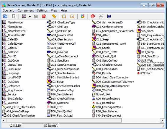
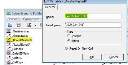
69
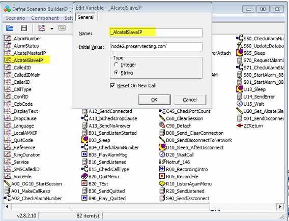
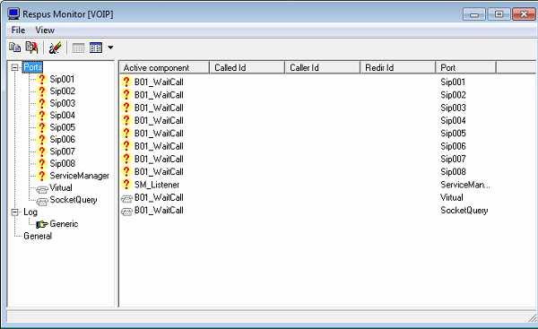
70

71 12 Appendix C: Alcatel-Lucent Enterprise Communication Platform: configuration requirements 12.1 Paging Configuration The notification server parameter has to be enabled supported devices 12.2 Alarming description and configuration Site survey before deployment The site survey is an important step to provide a reliable geo-location service. This step is needed to gather the information about the power level received by the DECT on different places of the site where the solution is deployed. The Alarm server should not only be able to treat the information received by the DECT handsets but also to locate precisely where the alarm has been sent from. The main problem without site survey could be a building having antennas on more than one floor. Without this study it is nearly impossible to locate a DECT handset by pure theoretical calculation. For example if the emergency team is searching someone having a heart attack on the wrong floor, the loss of time is important. The DECT handsets have the possibility to send information by a long press of different button. One way to do a site survey would be to interpret that information and compute it in a system containing the plan of the rooms and floors. There could be many ways to do a site survey but it is a mandatory step to sell a reliable alarm server
72 Equipment configuration General configuration To configure the basic telephonic functions of the 500 DECT please read the following document: - For OmniPCX Enterprise systems: Alcatel-Lucent 500 DECT Handset Alcatel-Lucent OmniPCX Enterprise User manual In the Technical Knowledge Base accessible via the Business Portal at (the Technical Knowledge link is on the right of the window) - For OmniPCX Office systems: Alcatel-Lucent 500 DECT Handset, Alcatel-Lucent OmniPCX Office User manual. In the Technical Knowledge Base accessible via the Business Portal (the Technical Knowledge link is on the right of the window) - Quick guide : Alcatel-Lucent 500 DECT Handset, User Guide. In the Technical Knowledge Base accessible via the Business Portal (the Technical Knowledge link is on the right of the window) To have more information about how to use the 8242 DECT handset, please refer to the following document: - Alcatel-Lucent 8242 DECT Handset, Localisation and notification management, Configuration documentation In the Technical Knowledge Base accessible via the Business Portal (the Technical Knowledge link is on the right of the window) Geolocation and Notification configuration Information about how to configure the geolocation specific parameters of the 500 DECT is contained in the documents: - Alcatel-Lucent 500 DECT Handset User guide Localisation and notification management Configuration guide In the Technical Knowledge Base accessible via the Business Portal (the Technical Knowledge link is on the right of the window) - Alcatel-Lucent 500 DECT Handset User guide Localisation and notification management User guide In the Technical Knowledge Base accessible via the Business Portal (the Technical Knowledge link is on the right of the window) For the 8242 DECT parameters please refer to the document: - Alcatel-Lucent 8242 DECT Handset, Localisation and notification management, User documentation In the Technical Knowledge Base accessible via the Business Portal (the Technical Knowledge link is on the right of the window) OmniPCX Enterprise Licences In order to use the Geolocation and Notification server, licenses to use DECT handsets and SIP trunk are needed on the OmniPCX Enterprise. The licensing has to be done using ACTIS tool and can be checked using spadmin command For DECT feature: 29 DECT/PWT Engine = 1 41 DECT register Max number of Dect handset that can register to CallServer. 175 Mobile users Max number of Dect handsets declared in management 345 SIP extension users Number of IP-Dect handsets like 500Dect 371 IPDect users Max number of IP-Dect handsets For SIP Trunking: 185 SIP gateway = SIP network links Max number of links to SIP networks. 467 ARS Max routing list that can be managed
73 Phones configuration No specific configuration is needed for the 500 DECT. They are declared in the OmniPCX Enterprise as normal DECT phones as every Geolocation and Notification information is handled by the Alarm server OmniPCX Enterprise Trunks configuration In order to configure the trunks needed for the link between the Alarm server and the OmniPCX Enterprise please refer to the expert technical document. This document can be found in the Technical Knowledge Base.
 with command mgr or a Graphical User Interface")

74 12.3 Parameters management in OmniPCX Enterprise ComServer The parameters management could be done using a terminal connection (Console, telnet or ssh) with command mgr or a Graphical User Interface with OmniVista8770 Network Management Center. The following screenshots came from this GUI management center Management of Automatic Call Routing to Main server Created a ARS Route Number command table


75 Management of External SIP Gateway to Alarm server Management of Prefix to call alarm server


76 Management of discriminator Discriminator number according to entities Discriminator link to ARS route list


77 Linking ARS with External SIP Gw and protocol Management of External trunk group


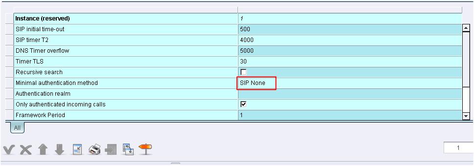
78 Internal SIP gateway.


79 DECT Creation DECT 500 should be created as SIP extension (IPTouch /8262DECT Creation DECT 8242 or 8262 should be created as Gap IBS-DECT To check management of IBS AP into OXE CS.


80 12.4 Management of IP-DECT To configure DAPs we need the DAP configurator (Dect-IP WEB interface for DAP Manager) Below screenshot describes the configuration of the DAP.

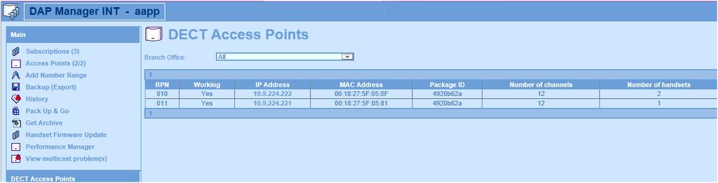
81 Registered Base stations Subscriptions
82 12.5 Configuration of Alarming in 500DECT On 500DECT, go to "Menu", select "settings" go to "Security», then "alarm settings" Enter Alarm Password (default 0000) Go to "Alarm status" Select type of alarms you want to use Go back in previous menu Select «Alarm mode» Select "Enterprise" Go to "Alarm server", "Server 1", then enter in "Number" the Trunk group prefix you ll use. Go back to main menu; the phone is ready Configuration of Alarming in 8242DECT Press the Menu key
83

84 13 Appendix D: AAPP member s escalation process Hotline: hotline@attag.ch
85 14 Appendix E: AAPP program 14.1 Alcatel-Lucent Application Partner Program (AAPP) * The Application Partner Program is designed to support companies that develop communication applications for the enterprise market, based on Alcatel-Lucent Enterprise's product family. The program provides tools and support for developing, verifying and promoting compliant third-party applications that complement Alcatel-Lucent Enterprise's product family. ALE International facilitates market access for compliant applications. The Alcatel-Lucent Application Partner Program (AAPP) has two main objectives: Provide easy interfacing for Alcatel-Lucent Enterprise communication products: Alcatel-Lucent Enterprise's communication products for the enterprise market include infrastructure elements, platforms and software suites. To ensure easy integration, the AAPP provides a full array of standards-based application programming interfaces and fullydocumented proprietary interfaces. Together, these enable third-party applications to benefit fully from the potential of Alcatel-Lucent Enterprise products. Test and verify a comprehensive range of third-party applications: to ensure proper inter-working, ALE International tests and verifies selected third-party applications that complement its portfolio. Successful candidates, which are labelled Alcatel- Lucent Enterprise Compliant Application, come from every area of voice and data communications. The Alcatel-Lucent Application Partner Program covers a wide array of third-party applications/products designed for voice-centric and data-centric networks in the enterprise market, including terminals, communication applications, mobility, management, security, etc.

86 Web site The Application Partner Portal is a website dedicated to the AAPP program and where the InterWorking Reports can be consulted. Its access is free at Enterprise.Alcatel-Lucent.com You can access the Alcatel-Lucent Enterprise website at this URL:

87 15 Appendix F: AAPP Escalation process 15.1 Introduction The purpose of this appendix is to define the escalation process to be applied by the ALE International Business Partners when facing a problem with the solution certified in this document. The principle is that ALE International Technical Support will be subject to the existence of a valid InterWorking Report within the limits defined in the chapter Limits of the Technical support. In case technical support is granted, ALE International and the Application Partner, are engaged as following: (*) The Application Partner Business Partner can be a Third-Party company or the ALE International Business Partner itself
Alcatel-Lucent Application Partner Program Inter-Working Report
 Alcatel-Lucent Application Partner Program Inter-Working Report Partner: EIFFAGE ENERGIE COMMUNICATIONS RESEAUX & SECURITE Application type: Alarm Server Application name: SIALert LOCALISE Alcatel-Lucent
ALCATEL-LUCENT OPENTOUCH NOTIFICATION SERVICE IMPROVE REAL-TIME SITUATIONAL AWARENESS AND PERSONAL SAFETY
 ALCATEL-LUCENT OPENTOUCH NOTIFICATION SERVICE IMPROVE REAL-TIME SITUATIONAL AWARENESS AND PERSONAL SAFETY In healthcare, education, high-risk industries and the hospitality sector, you must know immediately
Application Notes for Configuring NovaLink NovaAlert SIP with Avaya IP Office Issue 1.0
 Avaya Solution & Interoperability Test Lab Application Notes for Configuring NovaLink NovaAlert SIP with Avaya IP Office Issue 1.0 Abstract These Application Notes describe the configuration for connecting
OpenTouch Notification Service solution
 OpenTouch Notification Service solution Remote demo and self-training Lab Ed06 Contents 1 Introduction... 3 2 Set up the simulation environment... 3 2.1. RDP... 3 2.2. OTNS... 4 2.3. Your Phone as simulation
University. NewVoice. San Francisco Paris Geneva Zurich Linz Mainz Shanghai Brisbane Hong Kong São Paulo Dubai
 University Case Study University - Message Broadcast Powerful messaging scenarios to persons and groups, voice and text, dynamic and predefined. Messaging can be triggered via phone or web. With or without
Health Care. NewVoice. San Francisco Paris Geneva Zurich Linz Mainz Shanghai Brisbane Hong Kong São Paulo Dubai
 Health Care Emergency & Medical Services Nurse Call Heart Alarm Emergency Hotline Skill Based Mobilization Emergency Conference Bed Transportation MobiCall Health Care Security & Infrastructure MobiCall
Process alarm. Deliver messag e. Alarm event. Feedbac k. Process feedback
 Messenger@Net Messenger@Net Messenger@Net is a PC based middleware that delivers real-time alerting of significant enterprise events from virtually any input source to virtually any remote notification
Setting up and Managing Alarms in McAfee ESM 10.x
 McAfee SIEM Alarms Setting up and Managing Alarms in McAfee ESM 10.x Introduction McAfee SIEM provides the ability to send alarms on a multitude of conditions. These alarms allow for users to be notified
IndigoVision. GAI-Tronics Integration Module. Administrator's Guide
 IndigoVision GAI-Tronics Integration Module Administrator's Guide GAI-Tronics Integration Module THIS MANUAL WAS CREATED ON 10 APRIL 2013. DOCUMENT ID: IU-IM-MAN019-1 Legal Considerations LAWS THAT CAN
Using ANM Mobile CHAPTER
 CHAPTER 19 Date: 3/22/13 This chapter describes Cisco ANM Mobile, which allows you to access your ANM server or ANM Virtual Appliance and manage your devices using a mobile device such as an iphone or
Candidate APCO/CSAA ANS x: Alarm Monitoring Company to PSAP CAD External Alarm Interface Exchange
 Candidate APCO/CSAA ANS 2.101.1-200x: Alarm Monitoring Company to PSAP CAD External Alarm Interface Exchange Frequently Asked Questions published November 19, 2008 1. Are PSAPs required to adhere to the
Making the Most of Alarms
 Making the Most of Alarms Leverage the alarm management features of MPA to address network performance problems more effectively. Blueprint to Leverage Alarms and Alerts Using Mitel Performance Analytics
"VOICE OF SECURITY: Trends In Intercom, Public Address, and Mass Notification Emergency Communications
 "VOICE OF SECURITY: Trends In Intercom, Public Address, and Mass Notification Emergency Communications ASIS Houston Chapter Luncheon May 21, 2014 Paul Rux Director of Sales Mexico / South Central Region
A1UL PERS. Personal Emergency Response System. For Technical Support Please Contact Your Service Provider Or Distributor
 A1UL PERS Personal Emergency Response System TABLE OF CONTENTS 1. READ THIS FIRST... 1 2. SYSTEM OVERVIEW.. 1 3. COMPONENTS 2 4. UNIT OPERATION! Standby Mode.. 3! Emergency Activation. 3! Answering Incoming
Bosch TCU Integration Module Administrator's Guide
 Bosch TCU Integration Module 1.0 - Administrator's Guide 10 Dec 2008 Rev 1.2 Table of Contents 1 Overview... 3 1.1 Compatibility...3 1.2 References...3 2 Installation... 4 3 Configuration... 5 3.1 System
HELPY QUICK-TL GSM INTL
 Alarm system for elevators HELPY QUICK-TL GSM INTL QUICK GUIDE 04/02/16 DESCRIPTION A B C D E F G H I L M N O Connector for external LEDs Connector for built-in loudspeaker Built-in loudspeaker Connector
Simplex Panel Interface Guide
 Simplex Panel Interface Guide February 2016 SATEON Software Integrations Simplex Panel Interface Guide Issue 1.0, released February 2016 Disclaimer Copyright 2016, Grosvenor Technology. All rights reserved.
Oracle Communications Performance Intelligence Center
 Oracle Communications Performance Intelligence Center System Alarms Guide Release 10.2.1 E77506-01 June 2017 1 Oracle Communications Performance Intelligence Center System Alarms Guide, Release 10.2.1
Ion Gateway Cellular Gateway and Wireless Sensors
 Page 1 of 9 Account & Network Setup If this is your first time using the Ion Gateway online system site you will need to create a new account. If you have already created an account you can skip to the
Alarm Client. Installation and User Guide. NEC NEC Corporation. May 2009 NDA-30364, Revision 9
 Alarm Client Installation and User Guide NEC NEC Corporation May 2009 NDA-30364, Revision 9 Liability Disclaimer NEC Corporation reserves the right to change the specifications, functions, or features,
SimpleComTools, LLC 1
 COM1000-SNMP s Simple Network Management Protocol (SNMP) is a popular network management tool. Traditionally, SNMP was designed and used to gather statistics for network management and capacity planning.
Public Services. NewVoice. San Francisco Paris Geneva Zurich Linz Mainz Shanghai Brisbane Hong Kong São Paulo Dubai
 Public Services NewVoice San Francisco Paris Geneva Zurich Linz Mainz Shanghai Brisbane Hong Kong São Paulo Dubai Public Services - Mobile applications for smart phones - Emergency Call 911 - Municipality
Advisor Advanced Mobile Application User Manual
 Advisor Advanced Mobile Application User Manual Content Warnings and Disclaimers 2 Advanced Mobile 2 Contact information 2 Description 2 Screen navigation 4 Gestures 4 Menu 4 Help navigation 4 Login 5
Alarm Manager Plug-in
 Alarm Manager Plug-in User s Guide While every attempt is made to ensure both accuracy and completeness of information included in this document, errors can occur, and updates or improvements may be implemented
KELTRON LS 7000 ALARM MANAGEMENT SYSTEM Keltron Alarm Monitoring, Dispatch, and Reporting Software
 KELTRON LS 7000 ALARM MANAGEMENT SYSTEM Keltron Alarm Monitoring, Dispatch, and Reporting Software OVERVIEW The Keltron LS 7000 Alarm Management System software and computers make up the dispatch portion
BlackBerry AtHoc Networked Crisis Communication Siemens Indoor Fire Panel Installation and Configuration Guide Release Version 7.
 BlackBerry AtHoc Networked Crisis Communication Siemens Indoor Fire Panel Installation and Configuration Guide Release Version 7.3, October 2017 Copyright 2017 BlackBerry Limited. All Rights Reserved.
Preliminary. SmarteLight v1.2 Manual. Revision: 1.0 Date: 12/4/2012. Revision: 1.0 Page i OmniSite
 Preliminary Revision: 1.0 Date: 12/4/2012 Revision: 1.0 Page i OmniSite Table of Contents Table of Contents... ii Revision History... iii Notice...iv Warning...iv Limited Warranty...iv Contact Information...iv
Version 1.03 January-2002 USER S MANUAL
 Version 1.03 January-2002 1 USER S MANUAL 2 Version 1.03 January-2002 System Details CUSTOMER:...... PHONE:... FAX:... INSTALLED BY:...... PHONE:... FAX:... MAINTENANCE & SERVICE:...... PHONE:... FAX:...
Samsung SDS BMS Ver.2.0. Technical Specification
 Samsung SDS BMS Ver.2.0 Technical Specification Technical Specifications All rights and title, including all intellectual property rights to Samsung SDS BMS" is retained by Samsung SDS Co, Ltd. ("SDS"),
GMS GRAPHICAL MANAGEMENT SYSTEM
 GMS GRAPHICAL MANAGEMENT SYSTEM 1 GMS Security management system for multi-site organizations. PACOM Graphical Management System (GMS) is the modular client-server application that integrates all of PACOM
IndigoVision Alarm Panel. User Guide
 IndigoVision Alarm Panel User Guide THIS MANUAL WAS CREATED ON 2/21/2017. DOCUMENT ID: IU-AP-MAN002-4 Legal considerations LAWS THAT CAN VARY FROM COUNTRY TO COUNTRY MAY PROHIBIT CAMERA SURVEILLANCE. PLEASE
ArchestrA Direct Connect
 Table of Contents ArchestrA Direct Connect... 1 Introduction... 1 ArchestrA Direct Connection... 1 ArchestrA Data Source Definition... 2 Data Source Definition... 2 Importing Alarms from ArchestrA... 6
Operation Manual Fighter ProVision Software. Version: 0.0 Revision: 1
 Operation Manual Fighter ProVision Software Version: 0.0 Revision: 1 TABLE OF CONTENTS 1. Introduction 5 2. Software Installation 5 3. PC Users 6 3.1 Introduction 6 3.2 Default Code 6 3.3 Edit PC User
Certified Solution for Milestone
 Certified Solution for Milestone Araani SmokeCatcher Table of Contents Executive Summary... 4 Certified Products... 4 System Topology:... 5 Integrated Functionality... 7 Conclusion... 8 References... 8
Skyresponse ThingWorx Extension. Version 1.0. User Guide
 Skyresponse ThingWorx Extension Version 1.0 User Guide Software Change Log...1 Introduction...1 About Skyresponse...1 Installation...2 Importing the Skyresponse ThingWorx Extension...2 Configuration and
Quick Reference Guide
 infinite Prime with Hybrid Connections User Manual - Version 1.00 Catalog Number: ZI0473A (1/07) All data is subject to change without prior notice. Hereby, Electronics Line 3000 Ltd. declares that this
1. User features of the GSM dialer
 1. User features of the GSM dialer The JA60GSM dialer offers many useful features described in detail below. The installer should properly demonstrate the use of the system to the user after installation
SOLUTIONS FOR SENIOR CARE FACILITIES BUSINESS COMMUNICATION SERVERS
 SOLUTIONS FOR SENIOR CARE FACILITIES BUSINESS COMMUNICATION SERVERS BETTER CARE AND LOWER COSTS THE PANASONIC SOLUTION When empty beds equal lost revenue, patient satisfaction is more important than ever
Milestone SMI Intrepid II Perimeter Module 1.1 User s Manual
 Milestone SMI Intrepid II Perimeter Module 1.1 User s Manual Target Audience for this Document This document is aimed at system users and provides descriptions on how to install and maintain the Milestone
COMMUNICATOR ET08 / ET081
 COMMUNICATOR ET08 / ET081 User Manual v1.2 Safety instructions Please read and follow these safety guidelines in order to maintain safety of operators and people around: GSM communicator ET08 / ET081 (further
Any additional devices linked to the system ET08 (computer, sensors, relays etc.) must be approved by LST EN standard.
 must be approved by LST EN standard.") COMMUNICATOR ET08 User Manual v1.0 Safety instructions Please read and follow these safety guidelines in order to maintain safety of operators and people around: GSM communicator (gateway) ET08 (further
COMMUNICATOR ET08 User Manual v1.0 Safety instructions Please read and follow these safety guidelines in order to maintain safety of operators and people around: GSM communicator (gateway) ET08 (further
with internal sensor (channel 1) with an external sensor (channel 2) A-Editor software, Professional AK20 version (not for version AK4)
 with an external sensor (channel 2) A-Editor software, Professional AK20 version (not for version AK4)") Examples of use Example Creating an SMS-based alarm with confirmation A project file must first be created using the A-Editor software. This project file is then stored in the alarm modem. The alarm modem
Examples of use Example Creating an SMS-based alarm with confirmation A project file must first be created using the A-Editor software. This project file is then stored in the alarm modem. The alarm modem
Monitoring Solutions
 GSM Systems Monitor: Temperature, Humidity, Power, Water, Smoke, Carbon Monoxide and More September 2016 Table of Contents GSM Systems... 3 Argon 100 GSM... 3 Ares 12 & 14 GSM... 4 Poseidon2 4002... 5
Patriot Systems Limited
 COPYRIGHT 1997 - The Patriot Systems Ltd. Patriot Alarm Monitoring Automation Package is licensed for use on one computer, by the original person, or company, or organization whose name is registered with
MobiCall Silent Alarm
 MobiCall Silent Alarm In circumstances such as threats, MobiCall offers efficient personal security for employees at base and in the field, allowing a rapid alarm transmission in emergency and crisis situations.
SeCom Combining communication and security in retirement- and nursing homes
 SeCom Combining communication and security in retirement- and nursing homes Services Internet Call / Contact Center CTI / CRM Messaging Telephony Networking Whether yours is a medium-sized business or
Alarms for the Cisco ISA 3000
 About s This chapter gives an overview of the alarm system in the ISA 3000, and also describes how to configure and monitor alarms. About s, on page 1 Defaults for s, on page 3 Configure s, on page 3 Monitoring
Monitor Alarms and Events
 What Are Alarms and Events?, page 1 How are Alarms and Events Created and Updated?, page 2 Which Events Are Supported?, page 5 Set Alarm and Event Management Preferences, page 5 Interpret Event and Alarm
Figure 1. Proper Method of Holding the ToolStick. Figure 2. Improper Method of Holding the ToolStick
 CAN OBD READER REFERENCE DESIGN KIT USER GUIDE 1. Standard ToolStick Handling Recommendations The ToolStick Base Adapter and daughter cards are distributed without any protective plastics. To prevent damage
The WAVE Plus Instant Notification System for Schools and Colleges
 Instant Notification System for Schools and Colleges Duress alarm has been activated in the School of Engineering! Schools strive to provide a safe environment for students and teachers. In an emergency,
TELECOMMUNICATION. Telecommunication. Wireless Phone
 TELECOMMUNICATION Telecommunication Wireless Phone Talkback System CCTV PAGA TV Distribution LAN / WAN System 25 Telecommunication Telecommunication projects in the Oil & Gas industry are often large,
FiRe mobile-2 Operation Manual
 FiRe mobile-2 Operation Manual P/N 00-3230-505-0003-01 ISS 07JAN15 Copyright Trademarks and patents Manufacturer Version 2015 UTC Fire & Security. All rights reserved. The FiRe mobile-2 name and logo are
RAy SNMP. Application notes.
 Application notes. RAy SNMP. version 1.0 12/29/2017 RACOM s.r.o. Mirova1283 59231 Nove MestonaMorave CzechRepublic Tel.: +420565659 511 Fax: +420565659 512 E-mail: racom@racom.eu www.racom.eu Table of
ION Meter Alerts TECHNICAL NOTE NOVEMBER In This Document
 70072-0125-01 TECHNICAL NOTE NOVEMBER 2006 ION Meter Alerts A PowerLogic ION meter can send alerts to indicate a user specified power system condition such as a power quality problem (including surges,
Alarm System Example
 Alarm System Example ASD:Suite Copyright 2013 Verum Software Technologies B.V. ASD is licensed under EU Patent 1749264, Hong Kong Patent HK1104100 and US Patent 8370798 All rights are reserved. No part
Ademco Vista Alarm Panel
 System Galaxy Quick Guide CONFIGURATION AND OPERATION Ademco Vista Alarm Panel JAN 2018 SG 10.5.6 System Galaxy Quick Guide For Ademco Vista Panel Configuration & Operation 2nd edition JAN 2018 Information
IRIS Touch Firmware Enhancements and Additions from Version to Version
 Overview IRIS Touch Firmware Enhancements and Additions from Version 1.14.3 to Version 1.19.1 This document details enhancements to the feature set of the IRIS Touch from firmware Version 1.14.3 to Version
Rev C May GE Interlogix. Part No: R. CareGard. User Guide
 g 466-1936 Rev C May 2003 GE Interlogix www.ge-interlogix.com Part No: 60-883-95R CareGard User Guide FCC Notices FCC Part 15 Information to the User Changes or modifications not expressly approved by
Universal Monitoring System. TrapServer Description
 TrapServer Description TrapServer is a centralized or distributed monitoring system used to monitor, assess and control a multi-vendor telecommunications networks. It consists of a server (rack or desk
With Magictrl, you can control MatiGard anytime & anywhere via your smartphone, even without data network.
 MatiGard User Guide 02 Menu Feature-------------------------------------------------------------- 05 Overviews---------------------------------------------------------- 07 Read Before Using-----------------------------------------------
MODEL 5100 BROADBAND ALARM COMMUNICATOR INSTALLATION & USER S GUIDE PRODUCT ID #
 MODEL 5100 BROADBAND ALARM COMMUNICATOR INSTALLATION & USER S GUIDE PRODUCT ID # 19-25133-502 MODEL 5100 2011 Uplink Security LLC. All rights reserved. No part of this publication may be reproduced or
Cisco CallManager. Management Module Guide. Document 5116
 Notice Copyright Notice Copyright 2002-present by Aprisma Management Technologies, Inc. All rights reserved worldwide. Use, duplication, or disclosure by the United States government is subject to the
DATA SHEET BENEFITS CURRENT CHALLENGES SSM INFOTECH S X-FORCE AMS - THE IDEAL SOLUTION
 DATA SHEET BENEFITS Alarm Printers, Report Printer Replacement Better Operator Attention Alarm Rationalization Remote Viewing of Alarms Unlimited Archiving of Alarms\Event Messages Alarm Consolidation
Integration Test Plan
 Integration Test Plan Terminus Security Prepared by: Kai Chan Stephen Krenzel John O Meara Version: 1.0 1 Contents 1 Introduction 3 1.1 Purpose.................................. 3 1.2 Scope...................................
E911 Manual. Empowered by Innovation P/N E911. For additional resources, visit our Technical Support site on the web at
 Empowered by Innovation E911 Manual P/N 1093100E911 August 17, 2015 Printed in U.S.A. For additional resources, visit our Technical Support site on the web at http://www.necdsx.com. This manual has been
Monitor Alarms and Events
 This chapter contains the following topics: What Are Alarms and Events?, page 1 How are Alarms and Events Created and Updated?, page 2 Find and View Alarms, page 3 Set Alarm and Event Management Preferences,
Session VI Smart safety systems
 Session VI Smart safety systems September 09th, 2016 Kolkata Denzil D Enterprise security Building Technologies Siemens Ltd Siemens AG 2011. All rights reserved. Safety every where Hospital Office Residential
Milestone XProtect Alarm Matrix Integration 1.0
 Milestone XProtect Alarm Matrix Integration 1.0 Milestone XProtect Alarm Matrix Integration 1.0 Target Audience This document is aimed at system users and provides descriptions on how to install, configure
Contact Product Manager, with details of the application.
 Eaton Corporation Telecommunications Power Solutions Email: dc.info@eaton.com www.eaton.com/telecompower Application Note AN0100 SC200 SNMP Traps Last updated 14 June 2011 Applicable products Audience
Software Solutions FOR THE TELECOMMUNICATIONS INDUSTRY CTS ALARM SOLUTION
 Software Solutions CTS ALARM SOLUTION Accommodates Multiple Sessions Connects to Leading Switch Manufacturers Long-Term Storage of Data Streams Easy to Use Reports Customizable Notification System With
AGRI-ALERT 9600 ALARM SYSTEM USER MANUAL
 AGRI-ALERT 9600 ALARM SYSTEM USER MANUAL M 890-00279 rev. 14 K 895-00004 rev. 00 Manufacturer: Viatron Electronics 5200, Armand-Frappier St-Hubert (Quebec) Canada J3Z 1G5 WARNINGS The warranty can be void
Notice... 1 Trademarks... 1 US Patent Numbers... 1 Technical Services Contact Information... 2 Document Conventions... 2 Warranty...
 Table of Contents Preface 1 Notice... 1 Trademarks... 1 US Patent Numbers... 1 Technical Services Contact Information... 2 Document Conventions... 2 Warranty... 2 Chapter 1 Radius Overview 6 1.1 About
Lone Worker Duress Security Hazard Zone Remote Area Health Care DURESS & SAFETY TECHNOLOGIES I N T E R N A T I O N A L
 Lone Worker Duress Security Hazard Zone Remote Area Health Care DURESS & SAFETY TECHNOLOGIES www.duressandsafety.com.au Creating safer environments for people Increasingly organisations recognise the need
To activate using remote control: press [ ] key once. To activate using keyboard: on panel keyboard [ ] keys once.
![To activate using remote control: press [ ] key once. To activate using keyboard: on panel keyboard [ ] keys once.](/thumbs/93/113878877.jpg "To activate using remote control: press [ ] key once. To activate using keyboard: on panel keyboard [ ] keys once.") Table of Content 1.1General Description----------------------------------------------------------------------2 2.2System Setup-----------------------------------------------------------------------------3
Table of Content 1.1General Description----------------------------------------------------------------------2 2.2System Setup-----------------------------------------------------------------------------3
INSTRUCTION MANUAL. stay ahead - stay informed 1. THE APP
 INSTRUCTION MANUAL stay ahead - stay informed 1. THE APP This is an app that allows you to received information regarding your alarm system, and will in the near future replace our current sms service.
WIN-911: Advanced Alarm Notification Software
 THE MOST WIDELY USED ALARM NOTIFICATION PLATFORM IN INDUSTRY AND IIoT WIN-911: Advanced Alarm Notification Software Steve Szabo Regional Sales Director EMEA Agenda WIN-911 Background Value Proposition
1. Introduction. 2. Product overview
 1. Introduction The AG400011 GSM Alarm panel is a control panel that is compatible with other H-net security devices from Everspring, such as wireless sensors, remote keyfobs, tags, and keypad. With this
TYDOM 315. * _Rev.2* GSM domotics transmitter. 1. Presentation
 TYDOM 5 GSM domotics transmitter ) Présentation. Presentation Delta Dore hereby declares that the equipment complies with the essential requirements and other relevant provisions of the R&TTE Directive
Platform Services BACnet Alarm Management
 Description: Guide to understanding and setting up BACnet Alarms, visualizing real-time and historical BACnet alarms using AlarmWorX64 Viewer and logging them to SQL database using AlarmWorX64 Logger OS
1. Functions of GPS locator ETLOC-30S 3
 Contents 1. Functions of GPS locator ETLOC-30S 3 1.1 Direct view of the vehicle position on the map 3 1.2 Vehicle security 3 1.2.1 Vehicle protection 3 1.2.1.1 GPS protection 3 1.2.1.2 GPS higher level
User Guide. Contents. About this guide. i-on Style Security System
 i-on Style Security System User Guide Contents About this guide.... 1 About i-on Style... 2 System components.... 2 Control unit... 2 Detectors... 2 External sirens... 3 Remote controls... 3 HUA transmitters...
HikCentral Web Client. User Manual
 HikCentral Web Client User Manual Legal Information User Manual 2018 Hangzhou Hikvision Digital Technology Co., Ltd. About this Manual This Manual is subject to domestic and international copyright protection.
SeCom. Combining communication and security in retirement- and nursing homes
 SeCom OVERVIEW Combining communication and security in retirement- and nursing homes Whether yours is a medium-sized business or a global corporation, Avaya can put together a customized solution comprising
AXIS SNMP MIB. User Manual
 User Manual About this document This document describes how to use the AXIS Video SNMP MIB. Legal considerations Video and audio surveillance can be regulated by laws that vary from country to country.
Contents. Glossary
 Contents Glossary ------------------------------------------------------------------------------------------------------ 6 1. Introduction to the IDS 1632 -------------------------------------------------------------
GSM RFID VOICE Alarm System
 GSM RFID VOICE Alarm System User s Manual For a better understanding of this product, please read this user manual thoroughly before using it. CONTENTS [Function Instruction] [Control Panel] Control Panel
PERMACONN PM1030 Includes DI300. Installation Manual
 PERMACONN PM1030 Includes DI300 Installation Manual Radio Data Comms Unit 5/20-30 Stubbs Street Silverwater NSW 2128 Telephone: 02 9352 1777 Facsimile: 02 9352 1700 Introduction The PERMACONN system provides
Elderly Care Alarm System
 Introduction 24/7 Peace of mind for your family The GSM Elderly Care Alarm System is a new released smart solution for take care of senior, aged, elder or disabled people on their daily life. Big LED display
Basic Installation Manual
 SAR SAR-V.7 Program or Higher Alarm Equipment for Lifts Basic Installation Manual in HIDRA System controllers Revision 0 (EN) NOTES FROM THE MANUFACTURER Carlos Silva SA shall not be responsible for any
HikCentral Web Client. User Manual
 HikCentral Web Client User Manual Legal Information User Manual 2018 Hangzhou Hikvision Digital Technology Co., Ltd. About this Manual This Manual is subject to domestic and international copyright protection.
Patriot Systems Limited
 COPYRIGHT 1997 - The Patriot Systems Ltd. Patriot Alarm Monitoring Automation Package is licensed for use on one computer, by the original person, or company, or organisation whose name is registered with
Alarms Updated 03/26/2018
 Updated 03/26/2018 Table of Contents Alarms Alarms in OneView...1 Types of Alarms...1 Setting up Alarms...2 Alarm Configuration...4 Customize Alarm Parameters...5 List of Configured Alarms...7 Acknowledging
CG500SKE SKYEYE GATEWAY USER MANUAL VERSION OCTOBER Disclaimers and Copyright
 CG500SKE SKYEYE GATEWAY USER MANUAL CG500SKE SkyEYE Gateway VERSION 1.2 26 OCTOBER 2014 Disclaimers and Copyright Nothing contained in this publication is to be construed as granting any right, by implication
PX-iP Operating Manual Gateway
 PX-iP Operating Manual Gateway The original version of this instruction has been prepared in German in accordance with DIN EN 82079-1. Content EN 1 Notes on the operating manual 3 2 Safety instructions
communicall connect solutions sheet What is Communicall Connect? Who is it for? What does it consist of?
 solutions sheet communicall connect What is Communicall Connect? Communicall Connect is Tunstall s most advanced grouped housing communication system. Its innovative design builds upon the success of Tunstall
ETSI TS V1.1.1 ( )
") TS 101 570-3 V1.1.1 (2012-06) Technical Specification Electromagnetic compatibility and Radio spectrum Matters (ERM); Interoperability Testing for Maritime Digital Selective Calling (DSC) Radios; Part
TS 101 570-3 V1.1.1 (2012-06) Technical Specification Electromagnetic compatibility and Radio spectrum Matters (ERM); Interoperability Testing for Maritime Digital Selective Calling (DSC) Radios; Part
Alarm module for leak detection with webserver
 This instruction document consists of 2 parts : one part about the assembly of the components and one part about configuration and starting-up of the system. The assembly is done by the qualified installer
CompleteView Alarm Client User Manual. CompleteView Version 4.6.1
 CompleteView Alarm Client User Manual CompleteView Version 4.6.1 Table of Contents Introduction... 1 Overview...2 System Requirements...2 Configuration... 3 Starting the Alarm Client...3 Menus...3 File
600 Range Dialer Installation Manual. Version 1.0
 600 Range Dialer Installation Manual Version 1.0 The information contained is supplied without liability for any errors or omissions. No part may be reproduced or used except as authorised by contract
MobiCall. Unified Event Communication
 MobiCall Unified Event Communication We offer targeted alerting in case of emergency calls and fire alarms, comprehensive staff security, effi cient and reliable communication in case of emergency, fast