MICRO R SURVEY METER W/TISSUE EQUIVALENT DETECTOR OPERATIONS & MAINTENANCE MANUAL
|
|
|
- Claude Doyle
- 6 years ago
- Views:
Transcription
1 MICRO R W/TISSUE EQUIVALENT DETECTOR OPERATIONS & MAINTENANCE MANUAL SECTION CONTENTS SPECIFICATIONS DESCRIPTION THEORY OF OPERATION OPERATING CONTROLS OPERATING INSTRUCTIONS MAINTENANCE PARTS LIST DSM-501OPERATING INSTRUCTIONS Wm B. Johnson & Associates Inc. PO Box AEI Drive Ronceverte, West Virginia Lewisburg, West Virginia Telephone: johnnuc@access.mountain.net Fax:
2
3 DSM-501 QUICK START OPERATIONS INSTRUCTIONS THESE INSTRUCTIONS ASSUME THE DSM-501 AND PROBE HAVE BEEN CALIBRATED AND ARE READY FOR OPERATION 1. Turn the MAIN SELECTOR SWITCH to RATEMETER 2. LCD display should go through a brief self check cycle and return to Adjust the CPM/DOSE switch to DOSE position DISPLAY SHOULD INDICATE DOSE 4. Adjust the FAST/SLOW switch to FAST 5. If the audible click for each pulse from the detector is required depress the SPEAKER/ZERO Switch towards SPEAKER momentarily. Audible tick for each input pulse should be present 6. NORMAL background readings for the system will vary depending on where the user is located. Generally speaking the background will be 5-12 micro R in and area without elevated radiation levels. Operating with a FAST time constant will likely result in the readings varying over a wider range. Utilizing the SLOW time constant will result in more stable readings BUT WILL REQUIRE THE OPERATOR TO SCAN THE AREA OF INTEREST AT A MUCH SLOWER RATE. 9 The OPERATIONAL ALARM is set at 0 cpm. If a OPERATIONAL ALARM is required refer to 6.9 ADJUSTING THE ALARM SETPOINT 10.TO ZERO THE DISPLAY depress the ZERO switch towards ZERO for at least 3 SECONDS. 11.The DSM-501 system is calibrated in GAMMA DOSE. To use this operating mode simply adjust the CPM/DOSE switch to DOSE and display will display readings in micro R and Milli R. The system is calibrated to indicate up to 25 mr/hr. Readings above 30 mr/hr are likely to be inaccurate and the OVERRANGE ALARM audible and visual alarms will operate until the readings return to less than 30 mr/hr. The OVERRANGE ALARM CANNOT BE DISABLED EXCEPT BY ADJUSTMENT TO THE DSM-501 S INTERNAL COMPONENTS. 1. HIGH VOLTAGE = 810 VDC 2. LCD REFRESH RATE = 2 SECONDS 3. FAST TC = 20 SECONDS 4. SLOW TC= 100 SECONDS 5. CPM RANGE = KCPM 6. CPM ALARM = 0 7. CPM OVERANGE ALARM = NONE 8. DOSE RANGE = 0 25 mr/hr 9. DOSE OVERANGE ALARM = 30 mr/hr 10. DOSE ALARM = NONE DSM-501SETTINGS
4 1.0 SPECIFICATIONS INPUT SENSITIVITY DETECTOR PROBE LINEARIZATION µr/hr TISSUE EQUILIVANT PLASTIC SCINTILLATOR RANGES m R/hr, kcpm cps, msv/hr COUNT TIME RANGE ADJUSTMENT ELECTRICAL LINEARITY RESPONSE TIME FULL SCALE SECONDS IN 10 SECOND INCREMENTS AUTO RANGING ± 5% OF FULL SCALE DRIFT LESS THAN 5% TEMPERATURE COEFFICIENT HIGH VOLTAGE INTERNAL ADJUSTMENTS FOR CALIBRATION AND DEAD TIME FAST = SEC. SLOW = SEC. LESS THAN 0.2%/DEGREE C ADJUSTABLE VDC REGULATION ± 1% LOW VOLTAGE VDC & -5 VDC REGULATION ± 0.5 % BATTERY BATTERY OPERATION "AA" ALKALINE 200 HRS NOMINAL LCD READOUT LCD REFRESH RATE DIGIT.75 (19mm) TALL, µr/hr, mr/hr,cpm, KCPM, CPS, µsv/hr,msv/hr, Sv/HR SECONDS (.2 SEC INCREMENTS LCD BACKLIGHT SECONDS PER ACTIVATION FRONT PANEL BACKLIGHT SWITCH" RS-232 DATA OUTPUT TEMPERATURE RANGE HUMIDITY RANGE PIN MINIATURE SUB-D CONNECTOR. DATA ON LCD READOUT DUMPED WHEN DATA SWITCH IS ACTIVATED ON FRONT PANEL. -20 CENT. TO 50 CENT. 5-95% NON CONDENSING DIMENSIONS ¼"(184mm) X 2 ¾" (70mm) H X 6 5/8"(118mm) DEEP WEIGHT # (1.3kilos) INCLUDING BATTERIES Copyright 2010 Wm B. Johnson & Associates Inc. PAGE 2
5 1.0 SPECIFICATIONS - CONTINUED HOUSING HOUSING FINISH CALIBRATION SECURITY Ga. ALUMINUM WITH HEAVY DUTY CARRYING HANDLE LIGHT GRAY & DARK GRAY CATALYZED POLYURETHANE LATCHES THAT SECURE TOP A ND BOTTOM HOUSING ARE PROVIDED WITH HOLES FOR TAMPER RESISTANCE SEALS 2.0 DESCRIPTION The Model DSM-501is a ruggedized, multi purpose, state of the art, DIGITAL MICRO R RATEMETER/SCALER. The large easy to read digital LCD readout is utilized to display all relevant data from the internal detector in Cpm, Cps, Counts, µr/hr, mr/hr units. The GSM-501 does not require any external pc boards, pc downloads etc. to calibrate and operate. All of the controls necessary to calibrate the DSM-501 are contained in the instrument. Calibration data i.e. HV, dead time, count time, alarm setpoint & over range setpoint, fast tc, slow tc & HV can be displayed on the LCD. Diagnostic circuitry constantly monitors the battery, high voltage and detector condition and automatically indicates when operation is out of tolerance. A FAST/SLOW RESPONSE switch(that is adjustable) is available on the front panel to change the full scale response from seconds for FAST and seconds for SLOW. A speaker that produces a loud AUDIBLE CLICK for each probe pulse can be turned OFF or ON from the front panel. The ALARMS for OVERRANGE & OPERATING ALARM have a visual ALARM indicator in the LCD and a audible indication when the alarm has been activated. The OPERATING ALARM can be temporarily disabled from the front by toggling the ZERO switch. Durability is enhanced by heavy duty, cast aluminum construction and the direct interconnection of the industrial type printed circuit boards. 3.0 THEORY OF OPERATION 3.1 GENERAL: The DSM-501 utilizes the latest field proven, microprocessor circuitry to the internal tissue equivalent scintillation probe. The instrument can function as a regular ratemeter indicating the gamma dose or scaler with counting times from seconds in 10 second increments. The system changes ranges automatically and has separate non interacting controls for dose and dead time compensated cpm or cps calibration. Operation in either the counts/minute or dose mode for each probe is switch selectable from the front panel. The electronic circuitry is located on 2 heavy duty industrial type printed circuit boards that are directly interconnected to improve reliability and durability. All of the internal power is provided by highly regulated -5 vdc & +5 vdc (± 0.5%) low temperature coefficient power supplies. A separate high stability higher voltage power supply is provided,with a low temperature coefficient provides vdc (±1%) to operate probes with different HV requirements. AN OVER RANGE ALARM is available that produces a beeping audible alarm when the usable range of the probe has been exceeded. Diagnostic circuitry constantly monitors the power supply, high voltage supply and indicates out of tolerance operation by indicators on the LCD or by audible alert. A RS-232 data port can be proved by a 9 pin sub-d connector. Data is available at the connector when the DATA switch located on the front panel is depressed. A 9 pin sub-d to USB cable adapted is available as an option. Copyright 2010 Wm B. Johnson & Associates Inc. PAGE - 3
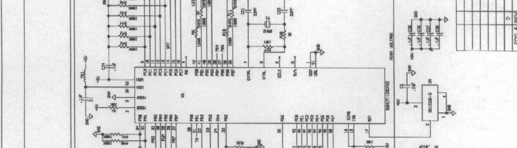
6 3.1 GENERAL- CONTINUED: 3.2 DETECTOR SIGNAL DIAGNOSTICS CALIBRATION CONTROLS A microprocessor meter operates much differently than a analog type meter. Most of the functions i.e. dead time correction, diagnostics etc. are provided by the microprocessor programming (software). The DSM-501contains two micro processors. One processor controls and manipulates the data from the probes and provides the HV and calibration support. The 2 nd processor on the DISPLAY pc board controls the data to the display and provides the RS-232 signal to the DATA OUTPUT CONNECTOR. Switch SW4 is an internal switch on the CPU that controls the CALIBRATION FUNCTIONS of the DSM-501. SW5 is a push button switch located by SW4 that is used to activate the calibration procedure selected and save the settings of the potentiometers utilized to calibrate each particular function. FIGURE 1& 2 shows SW4 and SW5 and their position on the CPU pc board. Calibration of the ALL THE PARAMETERS IN THE SYSTEM is completed by utilizing SW4, SW5, P1, P2 & P3. SW4 is utilized to select the function that will be calibrated or set and P1, P2, & P3 are utilized to adjust the parameters. When a particular function has been set (calibrated) to the desired levels SW5 is depressed to save the readings on P1, P2 & P3. Each position on SW4 represents a function or parameter that is being adjusted. As a result of this system the potentiometers P1, P2 & P3 are utilized over and over again to adjust the parameters. When the calibration procedure has been completed THE INSTRUMENT IS OPERATED WITH SW4 ADJUSTED TO 0 ZERO POSITION. FIGURE 2 & 2A SHOWS THE LOCATION OF SW4, SW5, P1, P2 & P3. FIGURE 3 SHOWS THE COMPONENT LAYOUT OF THE POWER SUPPLY PRINTED CIRCUIT BOARD AND THE LOCATION OF THE MAJOR COMPONENTS. 3.3 HIGH & LOW VOLTAGE POWER SUPPLIES Six "AA" size batteries provides the LOW VOLTAGE power for all of the DSM-501circuitry. The batteries are connected to a positive power regulator on the POWER SUPPLY pc board designated E1. E1 converts the 9 vdc to a very stable +5 vdc. The output of E1 (+5 vdc) is connected to the circuitry requiring +5 vdc and the negative 5 vdc regulator U2. The output of U2 (-5 vdc ) is connected to the circuitry requiring -5 vdc. Both power regulators (E1 & U2) have very good regulation ±.5% and a low temperature coefficient. The HIGH VOLTAGE supply is comprised of a special high efficiency transformer with a feedback winding and oscillator circuitry to generate a low ripple, stable high voltage. The output of the transformer T1 is connected to a voltage doubler circuit comprised of D1-D4 & C3- C7. The output of the doubler circuit is filtered in a pi type filter and connected to the PROBE BNC through R1. R1 is also the load resistor for the detector circuit. The HV oscillator circuit through R4 constantly monitors the high voltage. R4 provides U1 a low voltage signal that represents the high voltage. Any change in the high voltage will result in an appropriate increase or decrease in the power Q1 & Q2 provide the high voltage transformer. This "feedback" is utilized to regulate the high voltage to approximately ±1%. The power supply is designed with two high voltage outputs that can be independently adjusted between vdc. Figure 3 show the power supply pc board s major components and calibration controls opyright 2010 Wm B. Johnson & Associates Inc. PAGE 4
7 4.0 OPERATING CONTROLS & INDICATORS - FRONT PANEL FIGURE 1 SHOWS THE FRONT PANEL OPERATING CONTROLS 4.1 CONTROLS - MAIN FUNCTION SWITCH CONTROL SETTING OFF RATEMETER FUNCTION ALL POWER DISCONNECTED TO THE INSTRUMENT NORMAL OPERATING RATEMETER MODE CPM OR DOSE (BASED ON CS137 CALIBRATION) FOR PROBE 1 COUNT TIMED COUNT (SCALER) MODE FOR PROBE CONTROL DOSE /CPM Selects the operating mode of the ratemeter to measure in either roentgen or sieverts (BASED ON CS 137 CALIBRATION) or counts per minute. Probe response is automatically displayed in the correct (micro, milli or R/hr or sieverts) DOSE mode for the probe that has been selected on the MAIN SELECTION SWITCH. Operation in the CPM mode automatically includes the DEAD TIME correction for the probe that has been selected. 4.3 CONTROL SPEAKER/ZERO Control is a toggle switch with the center neutral. Toggling the switch for at least 3 seconds in ZERO direction instantly zeros the ratemeter. Momentary operation in SPEAKER direction turns speaker producing a tick for each input pulse from the detector on or off. THE AUDIBLE ALARM WILL REMAIN DISABLED UNTIL THE SIGNAL FALLS BELOW THE SETPOINT AT WHICH TIME THE ALARM CIRCUIT WILL RETURN TO NORMAL OPERATION. 4.4 CONTROL DATA/BACKLIGHT Control is momentary toggle switch with the center neutral. Momentary operation in DATA direction provides the data being displayed on the LCD to the RS-232 DATA OUTPUT CONNECTOR. Momentary operation in the BACKLIGHT direction will light the LCD BACKLIGHT FO 30 seconds. BACKLIGHT switch can be operated at the end of each 30 second cycle for another 30 second period for as long as necessary. Continued operation of the BACKLIGHT will greatly reduce the instruments battery life. 4.4 CONNECTORS FRONT PANEL None internal detector Copyright 2010 Wm B. Johnson & Associates Inc.PAGE 5
8 5.0 OPERATING INSTRUCTIONS SEE SPECIFIC INSTRUCTIONS IN THE REAR OF THIS MANUAL. 5.1 BEFORE OPERATION The DSM-501 HIGH VOLTAGE and GAIN are adjusted to the operating characteristics of theinternal probes supplied with the meter. 6.2 for High Voltage adjustment procedure and SECTION 6.3, 6.4 for the calibration of the system. Be sure the R/Sv and the CPM/CPS switch has be set to the proper units before calibrating the system. Figure 4 shows the location of the switch on the LCD pc board NO OTHER CHECKS ARE NECESSARY PRIOR TO OPERATING THE DSM-501 EXCEPT TO OBSERVE THE DIAGNOSTIC INDICATORS IN THE LCD DISPLAY WHEN THE UNIT IS FIRST TURNED ON. The internal microprocessor analyzes the internal parameters for a few seconds when the instrument is first turned on and during the instruments operation. All range, battery & probe diagnostic are turn on momentarily during start-up to show they are working. The display then reverts to NORMAL operation. The diagnostic circuits connected to the BATT & PROBE indicators continuously monitor the Circuitry for out of range operation. Battery voltage below 6.8vdc will light the BATT. Symbol on the LCD. Radiation fields that exceed the normal operating range of a probe in the DOSE mode will result in an audible beep & flashing alarm indication on the LCD every few seconds until the radiation field is reduced within the operating limits for the probe. 5.2 INSTRUMENT OPERATION - RATEMETER Adjust the MAIN SELECTOR switch to RATEMETER for normal ratemeter type operation Select the mode of operation CPM or DOSE(BASED ON CS 137 CALIBRATION) with the CPM/DOSE MODE SWITCH. CPM includes DEAD TIME correction. DOSE includes LINEARIZATION & DEAD TIME for the probe. DOSE CALIBRATION IS REFERED TO Cs The LCD READOUT can display the probe signals in CPM, COUNTS, ROETGEN AND SEIVERTS. When calibrating the system the decision to operate in CPM or CPS and ROETGEN OR SEIVERTS MUST BE MADE AND THE APPROPORIATE SWITCHES ADJUSTED BEFORE THE SYSTEM IS CALIBRATED. FIGURE 4 SHOWS THE LOCATION OF THE R/Sv SWITCH AND THE CPM/CPS SWITCH. Copyright 2010 Wm B. Johnson & Associates Inc PAGE 6
9 DSM INSTRUMENT OPERATION COUNT The count mode will count each individual pulse from the probe and display the count on the LCD. The system will be activated when the MAIN SELECTOR SWITCH is placed in the COUNT position. To start the counter from 0 counting time depress the ZERO SWITCH for at least 3 seconds. The COUNTING will appear and continue until the count cycle is complete. When the counting period is complete the COUNT will appear indicating the cycle is complete. To start another count cycle depress the ZERO switch for at least 3 seconds. If the system is adjusted to 0 seconds counting time then the system will continue to count as long as the MAIN SELECTOR SWITCH IS IN THE COUNT POSITION. See how to set count time. SW4 SW5 P 1 P 2 P 3 HV 1 HV 2 FIGURE 1 DSMDSM-501 FRONT PANEL CONTROLS & LOCATION OF MAJOR CAL CONTROLS Copyright 2010 Wm B. Johnson & Associates Inc.PAGE 7


10 DSM-501 FIGURE 2 DSMDSM-501 FRONT PANEL CONTROLS P/N REV 6 Copyright 2010 Wm B. Johnson & Associates Inc.PAGE 8

11 FIGURE 3 DSM-501 POWER SUPPLY AND MAJOR COMPONENTS P/N REV 1 Copyright 2010 Wm B. Johnson & Associates Inc.PAGE 9

12 FIGURE 4 DSM-501 LCD DIGITAL PC BOARD COMPONENTS AND CONTROLS P/N Copyright 2010 Wm B. Johnson & Associates Inc.PAGE 10
13 6.0 MAINTENANCE GENERAL: The DSM-501Digital Survey Meter can function as a CPM/CPS RATEMETER, DOSE CALIBRATED RATEMETER, SCALER WITH TIMED COUNTING FUNCTIONS Once the input has been calibrated the only operator intervention required is to select the type operation (ratemeter or count) with the MAIN SELECTORS SWITCH ON THE FRONT PANEL. No external devices are required to calibrate the system except a NIST traceable radioactive source and electronic pulse generator ALL CONTROLS NECESSARY TO CALIBRATE THE DSM-501 ARE LOCATED ON THE PC BOARDS OF THE SYSTEM. 6.1 LOCATION AND FUNCTION OF CALIBRATION CONTROLS GENERAL: The calibration procedure for the DSM-501 utilizes only 3 potentiometers and 2 switches to calibrate all of the DSM-501 s function. FIGURE 1 SHOWS THE GENERAL LOCATION OF THESE CONTROLS. SW4 located on the left side of the top pc board selects the function to be calibrated i.e. alarm setpoint, over range setpoint, calibration constant, dead time, count time, fast tc, slow tc, LCD refresh rate and probe high voltage. IMPORTANT: P1,P2,P3 ARE UTILIZED TO COMPLETE ALL CALIBRATIONS AND/0R ADJUSTMENTS. SW5 MUST BE DEPRESSED AFTER EACH ADJUSTMENT OR THE CALIBRATION WILL FAIL FIGURE 1 SHOWS THE GENERAL LOCATION OF THESE CONTROLS. SW4 located on the left side of the top pc board BESIDES SW5 selects the function to be calibrated. SW5 SAVES THE ADJUSTMENTS. These switch positions are as follows: POSITION 0 = NORMAL OPERATING POSITION POSITION 1 = DISPLAY & EDIT COUNT TIME SECONDS (10 SECOND INCREMENTS ADJ P1** POSITION 2 = DISPLAY & EDIT OPERATIONAL ALARM (5% - 95%) ADJ P1 COARSE P2 FINE** POSITION 3 = DISPLAY & EDIT OVER RANGE ALARM ADJ P1 COARSE P2 FINE** POSITION 4 = DISPLAY & EDIT CALIBRATION CONSTANT ADJ P1 COARSE P2 FINE P3 TENTHS** POSITION 5 = DISPLAY & EDIT DEAD TIME - ADJ P3** POSITION 6 = DISPLAY & EDIT HIGH VOLTAGE - MAIN SELECTOR TO #1 PROBE ADJ #1 HV MAIN SELECTOR TO #2 PROBE ADJ #2 HV DISPLAY READS IN VOLTS POSITION 7 = DISPLAYS SOFTWARE NUMBER INSTALLED IN INSTRUMENT POSITION 8 = DISPLAY & EDIT FAST & SLOW TC SET TO FAST ADJ P1 TO ( SECONDS) SET TO SLOW ADJ P1 TO ( SECONDS)** POSITION 9 = DISPLAY & EDIT LCD REFRESH RATE (8 = 0.8 SECONDS TO 30 = 3.0 SECONDS) ADJ P1 TO DESIRED REFRESH RATE** SW5 (located besides SW4) is utilized to activate ( CAL is visible in the upper center of the display when SW5 activates the calibration function) the function selected by SW4 and then save the data once the function has been calibrated. into the meters data base. Once a function has been selected by SW4 and activated by SW5 the potentiometers P1, P2 & P3 are utilized to input the calibration data. Once these potentiometers have calibrated the function SW5 MUST BE depressed OR the data WILL NOT BE SAVED RESULTING IN A FAILED CALIBRATION. This process is repeated for each SW4 position using the same P1, P2, & P3 for all data input. FIGURE 2 SHOWS THE LOCATION OF ALL THE CALIBRATION COMPONENTS. Copyright 2010 Wm B. Johnson & Associates Inc.PAGE 11
14 6.2 ADJUSTING THE METER FOR CPM/CPS AND R/Sv OPERATION The switches that adjust the DSM-501for Roentgen or Sieverts are locate on the LCD pc board. To access these switches remove the DSM-501 from it s housing. Looking at the bottom of the instrument with the LCD at the top the CPM/CPS switch is on the left side of the LCD pc board. The side of the board near the LCD will have CPS and CPM slide the small black switch lever towards the type operation desired The switch that selects the Roentgen or Sieverts is on the right side of the LCD pc board located directly above the push button switch SW5. Slide the small black switch lever in the direction of the desired units of measurement (mr/hr or Sieverts) This completes the adjustment of the DOSE UNITS AND COUNTING UNITS THAT WILL BE DISPLAYED ON THE LCD. 6.3 ADJUSTING THE HV FOR PROBE INPUT. (FIGURE 1, 2 & 3) Remove the DSM-501from it s housing Determine if the HV that is required to operate the #1 probe is correct Adjust the MAIN SELECTOR SWITCH TO RATEMETER POSITION Using a small screwdriver adjust SW4 to position 6. The number displayed will be the HV on the Probe. Adjust the #1 HV potentiometer to read the required HV (810 ±20 vdc) on the display Adjust the MAIN SELECTOR SWITCH TO RATEMETER POSITION Adjust SW4 to the 0 POSITION THIS COMPLETES THE ADJUSTMENT OF THE HV FOR THE PROBE. 6.4 DISABLING THE ALARM & OVERANGE ALARM BEFORE CALIBRATION To disable the OVER RANGE & REGULAR ALARM before calibrating adjust the MAIN SELECTOR switch to RATEMETER OR COUNT depending on which alarms you want disabled To disable the OVER RANGE ALARM adjust SW4 to position 3 and depress SW5 so that CAL is visible on display Adjust P1 & P2 clockwise until the display indicates Depress SW5. This completes disabling the OVERRANGE ALARM To disable the REGULAR ALARM Leave the MAIN SELECTOR SWITCH at the same setting as was used to disable the OVER RANGE ALARM Adjust SW4 to position 2 and depress SW5 until the CAL is visible on the display Adjust P1 & P2 until display indicates 0. Depress SW5 to save the reading. 6.5 ADJUSTING THE CALIBRATION CONSTANT FOR THE#1 & #2 PROBES ( FIGURE 1 & 2) GENERAL: The CALIBRATION CONSTANT adjustment is the CALIBRATION POINT for the LOW END OF THE PROBES OPERATING RANGE. This adjustment is completed utilizing P1, P2&P3. P2 acts as a COURSE adjustment and P1 acts as a FINE adjustment. P3 is utilized to adjust the 0.1 part of the display These potentiometers will become active for the calibration process when SW4 is in the correct position and SW5 is depressed. The CAL on the display will be visible when SW5 has been depress and the meter is in the CALIBRATION MODE. SW5 MUST BE DEPRESSED AT THE END OF THE ADJUSTMENT OR THE DATA WILL NOT BE SAVED Copyright 2010 Wm B. Johnson & Associates Inc. PAGE 12
15 PROBE CC ADJUSTMENT Remove the DSM-501from it s housing Determine the DOSE range of the probe that will be calibrated Adjust the MAIN SELECTOR SWITCH TO THE RATEMETER POSITION Adjust SW4 to the #4 position. Depress SW5 so that CAL is visible GM TYPE PROBE S CALIBRATION CONSTANT MUST BE CALIBRATED IN A RADIATION FIELD THAT PRODUCES LESS THAN 15KCPM (APPROX. 1% FULL SCALE ) TO PREVENT INTERACTION WITH THE DEAD TIME ADJUSTMENT. SCINTILLATION TYPE PROBES CAN BE SET IN FIELDS THAT ARE SOMEWHAT HIGHER DUE TO THE LOWER DEAD TIME OF SCINTILLATION PROBES. HOWEVER SCINTILLATION PROBE SHOULD HAVE THE CC SET IN AS LOW A FIELD AS PRACTICAL Adjust the DOSE/CPM switch to the DOSE POSITION Place the probe in a calibrated radiation field that will produce less than 15kcpm (ABOUT 1% OF FULL SCALE Adjust P1, P2 & P3 until LCD indicates the correct radiation field DEPRESS SW5 UNTIL CAL DISPPEARS THIS COMPLETES THE INITIAL SETTING OF THE CALIBRATION CONSTANT. 6.6 ADJUSTING THE DEAD TIME FOR THE PROBE (FIGURE 1 & 2) GENERAL: The DEAD TIME adjustment is the calibration point for the HIGH END OF THE PROBES OPERATING RANGE. The adjustment is completed utilizing potentiometer P3. The DEAD TIME adjustment will become active when SW4 is adjusted to position 5. P3 Will become active when SW5 is depressed and the CAL is displayed on the readout. #1 PROBE DT ADJUSTMENT Tthe full scale range for the tissue equivalent scintillation probe is 0 25mR/hr Be sure MAIN SELECTOR SWITCH is still in RATEMETER position and DOSE/CPM switch is in the DOSE POSITION Place the probe in a calibrated radiation field that is 70% - 90% of the probes NORMAL operating range Adjust SW4 to the #5 position. (The number that appears before depressing SW5 is the DT in micro seconds that is currently in the system.) Depress SW5 ONCE until CAL is displayed on readout Adjust P3 until the LCD indicates the correct value for the radiation field. Depress SW5 until CAL is not displayed on the readout. THIS SAVES THE DATA Adjust SW4 to 0 position (normal operating position). PANCAKE PROBE THAT HAS A NORMAL OPERATING RANGE OF 0 200mR/hr would be tested as follows to verify the accuracy of the overall calibration. Range 1 = 20% & 80% of 25 mr/hr Range 2 = 20% & 80% of 2.5 mr/hr Range 3 = 20% & 80% of 0.25 mr/hr Range 4 = 20% & 80% of mr/hr This procedure indicates after the CC & DT have been adjusted the meter readings should verified to ±10% at each of the radiation fields calculated for Range 1 Range 4. If the meter does not measure the 8 calibration points then the CC & DT calibration process will have to be repeated. Copyright 2010 Wm B. Johnson & Associates Inc. PAGE 13
16 6.7 ADJUSTING THE OVER RANGE ALARM GENERAL: The OVER RANGE ALARM is utilized to make the person operating the survey meter aware they have exceeded the normal operating limits of the survey meter and that the data is becoming inaccurate. The OVER RANGE ALARM is audible & has a visible blinking ALARM on the LCD panel and is indicated by the audio pulsing approximately 1 once per second. The alarm will stop when the field at the detector returns to normal operating range. In this procedure P1 & P2 are utilized to make the adjustments. P2 acts as a COURSE adjustment and P1 will act as a FINE adjustment. PROBE DOES NOT HAVE TO BE IN RADIATION FIELD FOR THIS ADJUSTMENT Adjust the MAIN SELECTOR switch to the input (RATEMETER 1 OR RATEMETER 2) that requires the OVERRANGE ALARM ADJUSTMENT Adjust SW4 to the #2 position. The number that appears will be the alarm setting that is currently established for the #1 input Depress SW5 (UNTIL CAL APPEARS) &Adjust P1 & P2 until the LCD indicates a reading that is 10% - 15% above the FULL SCALE range of the probe on the #1 input Depress SW5 until CAL disappears to save the data. Adjust SW4 to the NORMAL OPERATION POSITION 0 (ZERO) The survey meter is now ready for NORMAL OPERATION. 6.9 ADJUSTING ALARM SETPOINT GENERAL: THE DSM-501 HAS AN AUDIBLE ALARM THAT CAN BE SET INDEPENDENTLY FOR RATEMETE DOSE, RATEMETER CPM & COUNTS. THE SAME CONTROLS SW4, SW5, P1 & P2 ARE UTILIZED TO MAKE THESE ADJUSTMENTS. ADJUSTING THE ALARM SETPOINT TO R/hr or kcpm DISABLES THE ALARM ALARM SETPOINT RATEMETER DOSE Adjust the MAIN SELECTOR switch to RATEMETER Adjust the DOSE/CPM switch to DOSE Adjust SW4 to position 3. Depress SW5 until CAL appears Adjust P2 & P1 until the readout indicates the correct alarm setting Depress SW5 until CAL disappears to save data Return SW4 to the 0 (ZERO) POSITON FOR NORMAL OPERATION ALARM SETPOINT RATEMETER ADJUST THE MAIN SELECTOR SWITCH TO RATEMETER Adjust the DOSE/CPM switch to CPM Adjust SW4 to position 3. Depress SW5 until CAL appears Adjust P2 & P1 until the readout indicates the correct alarm setting Depress SW5 until CAL disappears to save data Return SW4 to the 0 (ZERO) POSITON FOR NORMAL OPERATION Copyright 2010 Wm B. Johnson & Associates Inc. PAGE 14
17 ALARM SETPOINT COUNTS GENERAL: THE DOSE/CPM SWITCH IS NOT IN SERVICE WHEN THE METER IS IN THE COUNT MODE OF OPERATION ADJUST THE MAIN SELECTOR SWITCH TO COUNT Adjust SW4 to position 3. Depress SW5 until CAL appears Adjust P2 & P1 until the readout indicates the correct alarm setting Depress SW5 until CAL disappears to save data Return SW4 to the 0 (ZERO) POSITON FOR NORMAL OPERATION To set the ALARM for the other position (#1 or #2) repeat the procedure with the MAIN SELECTOR switch in the other COUNT position TIMED COUNT GENERAL: THE DSM-501 HAS A TIMED COUNT FUNCTION WITH A RANGE OF SECONDS IN 10 SECOND INCREMENTS. THE TIME COUNT FUNCTION IS ONLY AVAILABLE FOR IN THE COUNT POSITION OF THE MAIN SELECTOR SWITCH.. THE SAME CONTROLS SW4, SW5, P1 & P2 ARE UTILIZED TO MAKE THE ADJUSTMENTS. FOR THE TIMED COUNT FUNCTION TIMED COUNT FUNCTION ADJUST THE COUNT TIME Adjust the MAIN SELECTOR SWITCH TO COUNT. Adjust SW4 to position 1. This displays the counting time in seconds currently in the system To set the count time to another time Depress SW5 until CAL appears Adjust P3 until readout indicates the correct counting time in seconds Depress SW5 until CAL disappears to save the data OPERATION IN THE TIME COUNT MODE Adjust the MAIN SELECTOR SWITCH to the COUNT position If count time is unknown adjust SW4 to the #1 position and COUNT TIME in seconds for that probe will be displayed. (CAUTION) DO NOT DEPRESS SW5 OR TIME COULD BE CHANGED) Return SW4 to the 0 position and instrument is ready for normal operation To start a time count cycle. Depress the ZERO SWITCH on the front panel When the ZERO switch is depressed the time count cycle will begin and the words COUNTING will appear on the display. When the cycle is complete the COUNTING will disappear and the words COUNT will appear. This indicates the count cycle has been complete The total counts will remain on the display until the ZERO switch is depressed or the instrument is turned OFF If the instrument remains ON a new count cycle can be started by DEPRESSING THE ZERO SWITCH on the front panel Copyright 2010 Wm B. Johnson & Associates Inc. PAGE 15
18 PARTS LIST Copyright 2010 Wm B. Johnson & Associates Inc. PAGE 16
19 7.0 PARTS LIST 7.1 DSM-501 LCD PC BOARD -- P/N JOHNSON P/N DESCRIPTION REFERENCE QUANTITY REQUIRED ****************************************************************************************** LCD DRIVE BRD REV I.C 4Kb FRAM SERIAL MEMORY I.C. 80 PIN FLASH MICRO CONTROLLER SWITCH ON-OFF-ON SW SWITCH TOGGLE SW TERMINAL STRIP 50 PIN J RESISTOR 100 OHM 5% R30, RESISTOR 10 OHM 5% R CAP. 10 PF 50 V C4, CAP. 100PF 50 V C RESISTOR 47K 5% R RESISTOR 10K 5% R9,11,12,13, R14, RESISTOR 1K 5% R CAP 0.1 MF 16 V 10% C1,6,7,8,9,13 C14,15,18,20 C21,22,23, CAP 47 MF 20V 10% C JUMPER 0 OHM R RESISTOR 100 OHM 5% R RESISTOR 100K 5% R2,3,4,5,6,21 R22,23,24,25 R26,27,28, TERM STRIP 50 PIN J TRANS. 60V 500ma Q FERRITE CHIP 2.5 A- 120 OHM FB2, FB CRYSTAL 10 MHZ (SMT) X SLIDE SWITCH SW3,SW DUAL SCHOTTKY DIODE 30V D CAP 2.2µF 25V 10% C2,3,10,12,19 C24, HEADER MALE PIN3 POS J I.C.OP AMP AD8628 U LCD DISPLAY JOHNSON LCD TERM STRIP LOW PROF. 50 PIN I.C. 3V 5.5 RS-232 DRIVER/REC U2 1 Copyright 2010 Wm B. Johnson & Associates Inc. PAGE 17
20 7.1 DSM-501 LOGIC BOARD -- P/N JOHNSON P/N DESCRIPTION REFERENCE QUANTITY REQUIRED ************************************************************************************************ SWITCH ON-OFF-ON SW SWITCH TOGGLE SW X 5/8 STANDOFF SWAGE RF CONN GOLD CONTACT PROBE 1, RESISTOR 2K 5% R RESISTOR 2.2K 5% R6,R CAP.01MF 50 V 20% C32, RESISTOR 20K 5% R RESISTOR 15K 5% R SWITCH RIGHT ANGLE PUSH BUTTON SW SWITCH 2 POL 6 POS SW SPACER #5 X 3/ SWITCH RIGHT ANGLE BCD SW I.C ON TIME PROG 8 BIT U RESISTOR 10K 5% R1,14,15,16,20,21,24 R26,47,59, RESISTOR 4.7K 5% R RESISTOR 100 OHM 5% R DIODE 100V D2,3,12, CAP.22MF 50V 10% C RESISTOR 220K 5% R RESISTOR 1K 5% R29,52,53, RESISTOR 1MEG 5% R22,31,33,55,56, CAP 0.1 MF 50 V 20% C1,3,5,8,14,15,16,17, C20,23,24,25,26,27,28, C29,30,31,33,34,35,36 C37,38,39,40, CAP 10MF 25V 10% C9,10,11, X5/8 SWAG STANDOFF TRAN BIPOLAR NPN 40V Q1,2, CAP 1MF 16V 10% C4, RESISTOR 82K 5% R RESISTOR 56 OHM R ECONORESET U DUAL DIODE D RESISTOR 560K 5% R LP339M I.C. U RESISTOR 1.6K 5% R6,7,8,9,10, I.C U RESISTOR 10 MEG 5% R CAP 22PF 50 V 5% C21,22, CAP 470 PF 16 V 10% C PIN SOCKET U FERRITE 1000 OHM 400ma FB1,FB RESISTOR 91K 5% R CAP 100PF 1KV 10% C12A DIODE SCHOTTKY 30V 30 ma D1,4,6,7,8, RESISTOR 249K 1% R25, RESISTOR 120 OHM 5% R SOCKET 10 PIN J3 1 Copyright 2010 Wm B. Johnson & Associates Inc. PAGE 18
21 7.1 DSM-501LOGIC BOARD -- P/N JOHNSON P/N DESCRIPTION REFERENCE QUANTITY REQUIRED ************************************************************************************************ X2MM RED LIGHT LED 1,2,3,4,5, JUMPER O OHMS J TEST POINTS TP1,2,3,4,5, RF CONN GOLD CONTACT PROBE I.C. 3 mhz OP AMP U RECTIFIER 12V 4.3 AMP Q FORM C 5 V 2 COIL LATCH RELAY RY mhz 18PF FUND Y PIN CONNECTOR J PIN CONNECTOR J V BUZZER 3kc SPK K POT 1 TURN P DIODE SCHOTTKY D K POT 1TURN P K 12TURN POT P1,2,3,4,5, PC BOARD W/LCD SUP SPEAKER GASKET DIE # ROTARY SWITCH MOD DSM-501 POWER SUPPLY BOARD -- P/N JOHNSON P/N DESCRIPTION REFERENCE QUANTITY REQUIRED K 1/8W 1206 PKG R MF 50V 1206 PKG C K 1/8W 1206 PKG R KEPNUT B1, W/MTG STRAP TRANSFORMER T X 2/8 UNDERCUT B1, K 1/8W 1206 PKG R16, 19, /8W 1206 PKG R VDC 200 MW DIODE D5, AA PC MOUNT BL. BAT. HOLDER B1, K 1/ PKG R4, M 1/8W 1206 PKG R K 1/8W 1206 PKG R V 1206P C8, 11, 12, 14, 18, 22, 23, NPN 40V SOT-23 Q MF 16V 1206 PKG C K 1/8W 1206 PKG R SOT-23 60V 150A PNP BIPOLAR Q V REGULATOR E MC33172D I.C. U1, K 1/8W 1206 PKG R 6, MF 16V C K 1/8 W 1206 R MF 50V 6032 PKG TANT. C MF 16V 3528 PKG. TANT C9, 17, A 600V RECTIFIER DIODE D OHM 1/ PKG R MF 20V 7343 PKG ROHS COMP C M ½ W 2010 PKG R1-3 3 Copyright 2010 Wm B. Johnson & Associates Inc. PAGE 19
22 JOHNSON P/N DESCRIPTION REFERENCE QUANTITY REQUIRED CMOS VOLTAGE CONVERTER U PF 3000V 1808 PKG C MF 2KV 2225 PKG C2, 3, 20, K 1/ PKG R MF 1KV 1808 PKG. C OHM JUMPER 1206 PKG R MINIATURE TEST POINTS TPG1, 2 TP M 1/8 W 1206 PKG. R45, K 4MM SQ. SINGLE TURN TRIMMING R7, 15, PIN.25 SQ SINGLE SOCKET J PIN.025 SQ SINGLE SOCKET J M 1/10W 0805 PKG R MUX/DMUX TRI 2CH ANLG. 16 SOTC 1.C. U4 1 Copyright 2010 Wm B. Johnson & Associates Inc. PAGE 20
23 SCHEMATICS Copyright 2010 Wm B. Johnson & Associates Inc. PAGE 21


24 DSM-501 Copyright Wm B. Johnson & Associates Inc. PAGE 22


25 DSM-501 Copyright Wm B. Johnson & Associates Inc. PAGE 23


26 DSM-501 Copyright 2010 Wm B. Johnson & Associates Associates Inc. PAGE 24
AM-806. Waste/Door Radiation Monitor OPERATIONS MANUAL
 AM-806 Waste/Door Radiation Monitor OPERATIONS MANUAL Section Contents 1. SPECIFICATIONS 2. MAIN COMPONENTS 3. THEORY OF OPERATION 4. OPERATING INSTRUCTIONS 5. INSTALLATION Page 2 1.0 SPECIFICATIONS SENSITIVITY
LUDLUM MODEL 44-9 ALPHA, BETA, GAMMA DETECTOR. February 2010 Serial Number PR and Succeeding Serial Numbers
 LUDLUM MODEL 44-9 ALPHA, BETA, GAMMA DETECTOR February 2010 Serial Number PR090405 and Succeeding Serial Numbers LUDLUM MODEL 44-9 ALPHA, BETA, GAMMA DETECTOR February 2010 Serial Number PR090405 and
Victoreen Primalert 35 Area Radiation Monitor
 Victoreen 05-437 Primalert 35 Area Radiation Monitor Operators Manual March 2005 Manual No. 126011 Rev. 3 2003, 2005 Fluke Corporation, All rights reserved. Printed in U.S.A. All product names are trademarks
F PC and AO OUTPUT BOARDS INSTRUCTION MANUAL. Blue-White. Industries, Ltd.
 F-2000 PC and AO OUTPUT BOARDS INSTRUCTION MANUAL Blue-White R Industries, Ltd. 500 Business Drive Huntington Beach, CA 92649 USA Phone: 714-89-8529 FAX: 714-894-9492 E mail: sales@blue-white.com or techsupport@blue-white.com
LUDLUM MODEL ALPHA, BETA, GAMMA HAND DETECTOR. June 2016 Serial Number and Succeeding Serial Numbers
 LUDLUM MODEL 44-25 ALPHA, BETA, GAMMA HAND DETECTOR June 2016 Serial Number 155835 and Succeeding Serial Numbers LUDLUM MODEL 44-25 ALPHA, BETA, GAMMA HAND DETECTOR June 2016 Serial Number 155835 and
LUDLUM MODEL 19A. Micro R Meter. May 2017 Serial No and Succeeding Serial Numbers
 LUDLUM MODEL 19A Micro R Meter May 2017 Serial No. 144020 and Succeeding Serial Numbers LUDLUM MODEL 19A Micro R Meter May 2017 Serial No. 144020 and Succeeding Serial Numbers Model 19A Micro R Meter
RAM GENE / RAM GENE-1
 RAM GENE / RAM GENE-1 Radiation Meters Operating Manual Document #PRIR69N0.DOC Version 6.1 - December 2000 ROTEM INDUSTRIES LTD. ROTEM Industrial Park P.O.Box 9046, Beer-Sheva 84190, ISRAEL Tel: 972-8-6571312/6568652
RAM GENE-1 ERK. Contamination & Radiation Meter. Operating Manual. Document #PRIR90N2.DOC Version 2.2 October 2009
 RAM GENE-1 ERK MK-Ι & MK-ΙΙ Contamination & Radiation Meter Operating Manual Document #PRIR90N2.DOC Version 2.2 October 2009 Version / Revision Log: RAM GENE-1 ERK/ Operating Manual Ver./Rev.# Date Revised
Nuclear Associates
 Nuclear Associates 05-575 MiniMonitor III Multipurpose X and Gamma Ray Survey Meter Operators Manual February 2005 Manual No. 05-575-1 Rev. 2 2004, 2005 Fluke Corporation, All rights reserved. Printed
Dosimeters/Survey meters
 Dosimeters/Survey meters 40 Gracechurch Str., EC3V OBT, London, United Kingdom (24 Hour Customer Line) 0044 208 720 6926 RAD-ION (RI-02) Especially designed for the Detection of Pulsed (Golden Engineering)
LUDLUM MODEL AND LUDLUM MODEL ALPHA, BETA, & GAMMA DETECTORS
 LUDLUM MODEL 44-9-18 AND LUDLUM MODEL 44-9-19 ALPHA, BETA, & GAMMA DETECTORS January 2018 Serial Number PR254331 and Succeeding Serial Numbers LUDLUM MODEL 44-9-18 AND LUDLUM MODEL 44-9-19 ALPHA, BETA,
LUDLUM MODEL 44-2 GAMMA SCINTILLATOR. February 2018 Serial Number PR and Succeeding Serial Numbers
 LUDLUM MODEL 44-2 GAMMA SCINTILLATOR February 2018 Serial Number PR361009 and Succeeding Serial Numbers LUDLUM MODEL 44-2 GAMMA SCINTILLATOR February 2018 Serial Number PR361009 and Succeeding Serial
LUDLUM MODEL 25 AND 25-1 PERSONAL RADIATION MONITOR USER S MANUAL. October 2014 Serial Number and Succeeding Serial Numbers
 LUDLUM MODEL 25 AND 25-1 PERSONAL RADIATION MONITOR USER S MANUAL October 2014 Serial Number 25000100 and Succeeding Serial Numbers LUDLUM MODEL 25 AND 25-1 PERSONAL RADIATION MONITOR USER S MANUAL October
PORTABLE ISOTOPE IDENTIFIER Search Tool / Sample Counting System
 FEATURES: HIGH GAMMA SENSITIVITY MULTI-CHANNEL ANALYZER (MCA) WORKS WITH VARIETY OF PROBES RADIONUCLIDE LIBRARY TAILORED TO CUSTOMER REQUEST SIMULTANEOUSLY MEASURES ; DISPLAYS; ALARMS 1-3 SEPARATE DETECTORS
NUCLEAR INDUSTRY STANDARD PROCESS Radiological Protection. Level 3 Information Use
 NUCLEAR INDUSTRY STANDARD PROCESS Radiological Protection Level 3 Information Use NISP-RP-001 Industry Approval Date: September 14, 2018 This is an industry document for standardizing radiation protection
Ranger EXP RADIATION A L E R T
 RADIATION A L E R T TM Ranger EXP INTERNATIONAL S.E. International, Inc. P.O. Box 39, 436 Farm Rd. Summertown, TN 38483 USA 1.800.293.5759 1.931.964.3561 Fax: 1.931.964.3564 www.seintl.com radiationinfo@seintl.com
LUDLUM MODEL 44-3 LOW ENERGY GAMMA SCINTILLATOR. May 2018 Serial Number PR and Succeeding Serial Numbers
 LUDLUM MODEL 44-3 LOW ENERGY GAMMA SCINTILLATOR May 2018 Serial Number PR134823 and Succeeding Serial Numbers LUDLUM MODEL 44-3 LOW ENERGY GAMMA SCINTILLATOR May 2018 Serial Number PR134823 and Succeeding
Contamination Meter Users Manual
 RDS-80 Contamination Meter U Users Manual Version 1.01 LAURUS Systems, Inc. - Ph: 410-465-5558 - Fax: 410-465-5257 - www.laurussystems.com NOTE This document and the information herewith are copyrighted
Sierra Model 951 Digital Flo-Box. Instruction Manual Part Number IM-951 Revision A 09-05
 Sierra Model 951 Digital Flo-Box Instruction Manual Part Number IM-951 Revision A 09-05 5 Harris Court, Building L Monterey, CA 93940 (831) 373-0200 (800) 866-0200 Fax (831) 373-4402 www.sierrainstruments.com
Portable Survey Instruments NISP-RP-01
 NUCLEAR INDUSTRY STANDARD PROCESS Radiological Protection NISP-RP-01 This is an industry document for standardizing radiation protection processes used by supplemental radiation protection technicians.
LUDLUM MODEL 3276 SERIES FRISKER/AREA MONITOR USER S MANUAL. November 2017 Serial Number: and Succeeding Firmware: 49830n30 and Higher
 LUDLUM MODEL 3276 SERIES FRISKER/AREA MONITOR USER S MANUAL November 2017 Serial Number: 25009185 and Succeeding Firmware: 49830n30 and Higher LUDLUM MODEL 3276 SERIES FRISKER/AREA MONITOR USER S MANUAL
DSGH. Radiation-Based Detector with GEN2000 Electronics for Density Measurement QUICK REFERENCE GUIDE
 DSGH Radiation-Based Detector with GEN2000 Electronics for Density Measurement QUICK REFERENCE GUIDE Revision History Revision History Version of manual Description Date 1.0 Initial release 051025 1.1
RTD TEMPERATURE SENSING SYSTEM
 General Overview RTD TEMPERATURE SENSING SYSTEM The Prime Technology RTD Temperature System 9219-00-0002 is a three-channel temperature measuring system that utilizes two RTD Temperature Sensor inputs
LUDLUM MODEL ALPHA/BETA RATEMETER. April 2018 Serial No and Succeeding Serial Numbers
 LUDLUM MODEL 177-84 ALPHA/BETA RATEMETER April 2018 Serial No. 128600 and Succeeding Serial Numbers LUDLUM MODEL 177-84 ALPHA/BETA RATEMETER April 2018 Serial No. 128600 and Succeeding Serial Numbers STATEMENT
LUDLUM MODEL DIGITAL RADIATION MONITOR WITH INTERNAL SCINTILLATOR. August 2010 Serial Number and Succeeding Serial Numbers
 LUDLUM MODEL 375-600 DIGITAL RADIATION MONITOR WITH INTERNAL SCINTILLATOR August 2010 Serial Number 179939 and Succeeding Serial Numbers 1 LUDLUM MODEL 375-600 DIGITAL RADIATION MONITOR WITH INTERNAL SCINTILLATOR
Carbon Monoxide Transmitter
 Introduction The CO Transmitter uses an electrochemical sensor to monitor the carbon monoxide level and outputs a field-selectable 4-20 ma or voltage signal. The voltage signal may also be set to 0-5 or
LUDLUM MODEL 2360 SCALER/RATEMETER DATA LOGGER. July 2016 Serial Number and Succeeding Serial Numbers
 LUDLUM MODEL 2360 SCALER/RATEMETER DATA LOGGER July 2016 Serial Number 133669 and Succeeding Serial Numbers LUDLUM MODEL 2360 SCALER/RATEMETER DATA LOGGER July 2016 Serial Number 133669 and Succeeding
LUDLUM MODEL RK2 RESPONSE KIT. October 2017 Serial Number and Succeeding Serial Numbers
 LUDLUM MODEL 2241-3RK2 RESPONSE KIT October 2017 Serial Number 238342 and Succeeding Serial Numbers LUDLUM MODEL 2241-3RK2 RESPONSE KIT October 2017 Serial Number 238342 and Succeeding Serial Numbers STATEMENT
Area Monitor/Frisker Count Rate Meter Victoreen
 Area Monitor/Frisker Count Rate Meter Victoreen Model 190F! Adjustable Alarm! Backlit analog/digital display! Interchangeable probe adapter module! Multiple probe use! Redundant power supply! Available
Operating Instructions
 LP D-TEK Vehicle Loop Detector Operating Instructions This product is an accessory or part of a system. Always read and follow the manufacturer s instructions for the equipment you are connecting this
Operating Instructions
 D-TEK Vehicle Loop Detector Operating Instructions This product is an accessory or part of a system. Always read and follow the manufacturer s instructions for the equipment you are connecting this product
Sierra Series 900 Single & Dual Channel System. Instruction Manual
 Series 240/24 Instruction Manual Table of Contents Sierra Series 900 Single & Dual Channel System Instruction Manual Part Number IM-90-07/05 Revision D. 5 Harris Court, Building L Monterey, CA 93940 (83)
LUDLUM MODEL ALARM RATEMETER. June 2017 Serial Number and Succeeding Serial Numbers
 LUDLUM MODEL 177-61 ALARM RATEMETER June 2017 Serial Number 101825 and Succeeding Serial Numbers LUDLUM MODEL 177-61 ALARM RATEMETER June 2017 Serial Number 101825 and Succeeding Serial Numbers STATEMENT
SENSIT HXG-2d. SENSIT TECHNOLOGIES 851 Transport Drive Valparaiso, IN Phone: (219) Fax: (219)
 Fax: (219)") WARRANTY AND REPAIR POLICY Your SENSIT HXG-2d instrument is warranted to be free from defects in materials and workmanship for a period of two years after purchase (excluding sensor, calibration and batteries).
WARRANTY AND REPAIR POLICY Your SENSIT HXG-2d instrument is warranted to be free from defects in materials and workmanship for a period of two years after purchase (excluding sensor, calibration and batteries).
Victoreen 942A-200. Operators Manual. Universal Digital Ratemeter
 Victoreen 942A-200 Universal Digital Ratemeter Operators Manual February 2005 Manual No. 942A-200-1 Rev. 4 2004, 2005 Fluke Corporation, All rights reserved. Printed in U.S.A. All product names are trademarks
Using the GammaRAE II Personal Radiation Detector
 Using the GammaRAE II Personal Radiation Detector GammaRAE II Features Normal Usage Turning Unit On Operating Mode User Screens Advanced Features Programming Mode Training Agenda GammaRAE II Features Detector:
Communications None RS-232C RS-422* RS-485* BCD Transmission output*/** (4 to 20 ma) E5AX- E5AX- L(M)A02 L(M)A03
 E5AX- E5AX- L(M)A02 L(M)A03") Digital Controller A 96 x 96-mm (DIN) Digital Process Controller Optimum PID control with feed-forward control circuitry. High accuracy (+0.3% FS +1 digit max.). Replaceable Output Units. Models with communications
Digital Controller A 96 x 96-mm (DIN) Digital Process Controller Optimum PID control with feed-forward control circuitry. High accuracy (+0.3% FS +1 digit max.). Replaceable Output Units. Models with communications
LUDLUM MODEL RK RESPONSE KIT. January 2016 Serial Number and Succeeding Serial Numbers
 LUDLUM MODEL 2241-2RK RESPONSE KIT January 2016 Serial Number 237627 and Succeeding Serial Numbers LUDLUM MODEL 2241-2RK RESPONSE KIT January 2016 Serial Number 237627 and Succeeding Serial Numbers STATEMENT
LUDLUM MODEL 52 PORTABLE PORTAL MONITOR. November 2011 Serial No and Succeeding Serial Numbers
 LUDLUM MODEL 52 PORTABLE PORTAL MONITOR Serial No. 175872 and Succeeding Serial Numbers LUDLUM MODEL 52 PORTABLE PORTAL MONITOR Serial No. 175872 and Succeeding Serial Numbers TABLE OF CONTENTS 1. GENERAL...
Microprocessor Digital Thermometer
 Microprocessor Digital Thermometer Instruction Manual Models 819A, 820A and 821A This owner s manual was as current as possible when this product was manufactured. However, products are constantly being
DOE 2.17 Contamination Monitoring Instrumentation Study Guide. 00ICP330 Rev. 0 Page 1 of 23
 00ICP330 Rev. 0 Page 1 of 23 Course Title: Radiological Control Technician Module Title: Contamination Monitoring Instrumentation Module Number: 2.17 Objectives: 2.17.01 List the factors which affects
LUDLUM MODEL 26-1 FRISKER USER S MANUAL. April 2017 Serial Number PF and Succeeding Serial Numbers
 LUDLUM MODEL 26-1 FRISKER USER S MANUAL April 2017 Serial Number PF002366 and Succeeding Serial Numbers LUDLUM MODEL 26-1 FRISKER USER S MANUAL April 2017 Serial Number PF002366 and Succeeding Serial Numbers
Troubleshooting Thermo Scientific LevelPRO Gauges
 Troubleshooting Thermo Scientific LevelPRO Gauges Key Words Scintillation detector Current board Relay output Communications Level indication Purpose A chapter in the user guide for the Thermo Scientific
Smoke Check Service Manual
 Contents page ON OFF smoke Safety Precaution 2 Important safeguards 2 Looking after your Smoke Check 2 Introduction 2 Before you begin 2 Smoke Check system overview 3 CO sensor 5 Smoke Check exploded view
MVP-D-TEK Vehicle Loop Detector 9 Volts DC to 240 Volts AC. Operating Instructions
 MVP-D-TEK Vehicle Loop Detector 9 Volts DC to 240 Volts AC Operating Instructions We have designed the new MVP-D-TEK vehicle loop detector with the following objectives in mind: 1. Compact package to allow
Table of Contents SECTION PAGE SECTION 1 INTRODUCTION Description Features Models... SECTION 2 RS-232 COMMUNICATIONS...
 SECTION Table of Contents SECTION 1 INTRODUCTION...................... 1.1 Description............................... 1.2 Features................................. 1.3 Models..................................
HI-3510 RF Radiation Badge Broadband Electromagnetic Radiation Detector User s Manual
 HI-3510 RF Radiation Badge Broadband Electromagnetic Radiation Detector User s Manual Copyright 1996 by Holaday Industries, Inc. Manual #600071 10/97 $20.00 Revision Record Manual #600071 HI-3510 Radiation
DYGIZONE GJD910 Lighting Controller & Enunciator
 DYGIZONE GJD910 Lighting Controller & Enunciator MASTER WIRING IDENTIFICATION Power up to the DygiZone and you will see: All the LED s (red,yellow,green and blue buttons) will flash All the LCD icons will
LUDLUM MODEL 26 FRISKER USER S MANUAL. December 2016 Serial Number PF and Succeeding Serial Numbers
 LUDLUM MODEL 26 FRISKER USER S MANUAL December 2016 Serial Number PF001075 and Succeeding Serial Numbers LUDLUM MODEL 26 FRISKER USER S MANUAL December 2016 Serial Number PF001075 and Succeeding Serial
SENSIT HXG-2d Combustible Gas Detector INSTRUCTION MANUAL Read and understand Instructions before use. PENDING Ex. II3G Ex ic llb T3 IP20
 SENSIT HXG-2d Combustible Gas Detector INSTRUCTION MANUAL Read and understand Instructions before use. PENDING Ex II3G Ex ic llb T3 IP20 PENDING (USA) Class 1, Zone 2, AEx nl llb T3 PENDING (Canada) Class
II 2 G. SENSIT HXG-2d. Ex ib IIB T3 IP20. Suitable for combustible gases such as Methane, Butane, Propane and Natural Gas MADE IN USA
 SENSIT HXG-2d Combustible Gas Detector INSTRUCTION MANUAL Read and understand Instructions before use. PENDING II 2 G Ex ib IIB T3 IP20 PENDING (USA) Class 1, Division 1, Groups C and D, T3 Suitable for
OVEN INDUSTRIES, INC.
 OVEN INDUSTRIES, INC. OPERATING MANUAL Model 5C7-252 TEMPERATURE CONTROLLER With PLC Inputs Introduction Thank you for purchasing our controller. The Model 5C7-252 is an exceptionally versatile unit and
PACSystems* RX3i. Thermocouple Input Module, 12 Channels, IC695ALG412. GFK-2578B October 2011
 October 2011 PACSystems* RX3i Thermocouple Input Module, 12 Channels, IC695ALG412 The PACSystems * Thermocouple Input module IC695ALG412 provides twelve isolated differential thermocouple input channels.
T-32-TS Touchscreen Thermostat. Installation Manual
 T-32-TS Touchscreen Thermostat Installation Manual TABLE OF CONTENTS Introduction...4 Getting Started...5 Installing the Thermostat...6, 8 Disassembly...6 Thermostat Location...6 Mounting the Subbase...6,
Duct and Rough Service Carbon Monoxide Sensor
 Product Identification and Overview Duct and Rough Service Carbon Monoxide Sensor BAPI s Carbon Monoxide Sensor offers enhanced electrochemical sensing with outstanding accuracy at low concentrations.
MODEL 5800A CARBON MONOXIDE (CO) MONITOR AND ALARM SAMPLE-DRAWING TYPE
 MONITOR AND ALARM SAMPLE-DRAWING TYPE") MODEL 5800A CARBON MONOXIDE (CO) MONITOR AND ALARM SAMPLE-DRAWING TYPE 11//07 A153-021500-1 INSTRUCTION MANUAL - MODEL 5800A CO ALARM I INTRODUCTION This MST Model 5800A Carbon Monoxide (CO) Alarm is a
MODEL 5800A CARBON MONOXIDE (CO) MONITOR AND ALARM SAMPLE-DRAWING TYPE 11//07 A153-021500-1 INSTRUCTION MANUAL - MODEL 5800A CO ALARM I INTRODUCTION This MST Model 5800A Carbon Monoxide (CO) Alarm is a
STT 3000 Series STT250 Smart Temperature Transmitters Specifications Models STT25T EN0l-6091 February 2009
 STT 3000 Series STT250 Smart Temperature Transmitters Specifications Models STT25T EN0l-6091 February 2009 Introduction Honeywell s STT 3000 family of microprocessor based transmitters covers the full
Dryer Controller M720
 User Manual Dryer Controller M720 Hardware version 2.00 Software version 2.00 Manual M720 Dryer controller Page 1 of 60 Document history Preliminary version: - Created in April, 2009 Hardware Version 2.00,
tcm100, tcm101 Series Temperature Control Modules and PTS100, PTS100/3 Pipe Temperature Sensors Operations Manual
 tcm100, tcm101 Series Temperature Control Modules and PTS100, PTS100/3 Pipe Temperature Sensors Operations Manual This manual covers operation of the tcm100 and tcm101 Series Temperature Control Modules.
Pump-Down Controller MODEL 4052
 Pump-Down Controller 4-20mA Input/Scalable Output Seal Fail Monitoring Duplex Pump Alternation Hand-Off-Auto Controls Dual Run-time Meters RS-485/Modbus Communications DESCRIPTION The Model 4052 Pump-Down
SENSIT HXG-2d Combustible Gas Detector
 INSTRUCTION MANUAL SENSIT HXG-2d Combustible Gas Detector Read and understand instructions before use. 710183 UL 913 Intrinsically Safe for Use in Class I, Groups C and D, T3 Hazardous Locations For use
300/400 UNITS - MODULAR CONFIGURATION
 300/400 UNITS - MODULAR CONFIGURATION 300/400 UNITS - MODULAR CONFIGURATION TRITIUM MONITORS ESSENTIAL CHARACTERISTICS, FEATURES AND OPTIONS These are line powered tritium monitors for continuous unattended
USER MANUAL Digital CO Monitor Model CO30
 USER MANUAL Digital CO Monitor Model CO30 Additional User Manual Translations available at www.extech.com Introduction Thank you for selecting the Extech Instruments Model CO30. The CO30 is a 3 in one
D-TEK O P E R A T I N G I N S T R U C T I O N S V E HI C L E L O O P DETECTOR Johnston Parkway, Cleveland, Ohio 44128
 O P E R A T I N G I N S T R U C T I O N S D-TEK V E HI C L E L O O P DETECTOR 4564 Johnston Parkway, Cleveland, Ohio 44128 P. 800 426 9912 F. 216 518 9884 Sales Inquiries: salessupport@emxinc.com Technical
PRM470 Portable Monitor Operation and Service Manual D00092 June 02, 2016 Rev. 2
 PRM470 P/N D00092 PRM470 Portable Monitor D00092 June 02, 2016 PRM470 P/N D00092 Foreword Thank You for choosing a Rapiscan Detection product. This manual is intended for the installation and normal daily
Analox 1000 Series. User Manual. Analox Sensor Technology Ltd. 15 Ellerbeck Court, Stokesley Business Park North Yorkshire, TS9 5PT, UK
 Analox 1000 Series User Manual Analox Sensor Technology Ltd. 15 Ellerbeck Court, Stokesley Business Park North Yorkshire, TS9 5PT, UK T: +44 (0)1642 711400 F: +44 (0)1642 713900 W: www.analox.net E: info@analox.net
DIGITAL AREA RADIATION MONITOR
 RADIATION DETECTION AND MONITORS 103 AREAEXPERT DIGITAL AREA RADIATION MONITOR Touch screen LCD Colorful visual and audio indications Network compatible with CenterExpert software PC controllable Easily
Advanced Test Equipment Rentals ATEC (2832) LS-1310/1550 Laser Source. Service Information Sheet.
 LS-1310/1550 Laser Source. Service Information Sheet.") Established 1981 Advanced Test Equipment Rentals www.atecorp.com 800-404-ATEC (2832) LS-1310/1550 Service Information Sheet Introduction This Service Information Sheet provides the following service information
Established 1981 Advanced Test Equipment Rentals www.atecorp.com 800-404-ATEC (2832) LS-1310/1550 Service Information Sheet Introduction This Service Information Sheet provides the following service information
LUDLUM MODEL 35 SERIES DIGITAL SURVEY METER USER S MANUAL
 LUDLUM MODEL 35 SERIES DIGITAL SURVEY METER USER S MANUAL September 2016 LUDLUM MODEL 35 SERIES DIGITAL SURVEY METER USER S MANUAL September 2016 STATEMENT OF WARRANTY Ludlum Measurements, Inc. warrants
MODEL A-316 CARBON MONOXIDE (CO) MONITOR AND ALARM FOR COMPRESSED AIR TESTING
 MONITOR AND ALARM FOR COMPRESSED AIR TESTING") MODEL A-316 CARBON MONOXIDE (CO) MONITOR AND ALARM FOR COMPRESSED AIR TESTING FOR OPERATION FROM 115 AC POWER Andersen Medical Gas 12 Place Lafitte Madisonville, LA 70447 http://www.themedicalgas.com 1-866-288-3783
MODEL A-316 CARBON MONOXIDE (CO) MONITOR AND ALARM FOR COMPRESSED AIR TESTING FOR OPERATION FROM 115 AC POWER Andersen Medical Gas 12 Place Lafitte Madisonville, LA 70447 http://www.themedicalgas.com 1-866-288-3783
OVERVIEW ANNUCIATOR POINTS
 4908 McKenna Ct., Columbus, Ohio, 43221 USA (614) 876-6345 www.aircraftextras.com sales@aircraftextras.com Model: AG6 Aircraft Annunciator, Volt/Amp/Temp Meter, Oil Gauge & Fuel Gauge in one Push Button
Pump-Up Controller MODEL 4062
 Pump-Up Controller 4-20mA Input/Scalable Output Seal Fail Monitoring Duplex Pump Alternation Hand-Off-Auto Controls Dual Run-time Meters RS-485/Modbus Communications DESCRIPTION The Model 4062 Pump-Up
LUDLUM MODEL 44-7 Alpha, Beta, Gamma Detector. July 2012 Serial No. PR and succeeding Serial Numbers
 LUDLUM MODEL 44-7 Alpha, Beta, Gamma Detector July 2012 Serial No. PR090405 and succeeding Serial Numbers LUDLUM MODEL 44-7 Alpha, Beta, Gamma Detector July 2012 Serial No. PR090405 and succeeding Serial
20 Light Remote Annunciator
 Light Remote Annunciator Owner s Manual Surface Mount Flush Mount 94-95- Standard Annunciator 94-, 94-95-, 95-4- 4- Annunciator w/remote Relay Panel 4-, 4-4-, 4-49-, 49-49-, 49- Time Multiplexed Annunciator
MODEL AND MODEL GAS PROPORTIONAL DETECTORS. December 2016 Serial No and Succeeding Serial Numbers
 MODEL 43-37 AND MODEL 43-37-1 GAS PROPORTIONAL DETECTORS Serial No. 086152 and Succeeding Serial Numbers MODEL 43-37 AND MODEL 43-37-1 GAS PROPORTIONAL DETECTORS Serial No. 086152 and Succeeding Serial
POSITRON EMISSION TOMOGRAPHY (PET) CENTER MONITORS
 CENTER MONITORS") RADIATION MONITORING SYSTEMS POSITRON EMISSION TOMOGRAPHY (PET) CENTER MONITORS Featuring: Radiological Assessment Display and Control Software (RADACS) Answers And Reports At Your Fingertips Aptec-NRC
RADIATION MONITORING SYSTEMS POSITRON EMISSION TOMOGRAPHY (PET) CENTER MONITORS Featuring: Radiological Assessment Display and Control Software (RADACS) Answers And Reports At Your Fingertips Aptec-NRC
HGM300/RDM800 PREVENTATIVE MAINTENANCE AND TECHNICAL SUPPORT. SECTION 1 HGM300 CPU reset, RDM800 CPU reset, WARM UP notes and HGM300 Self Test
 HGM300/RDM800 PREVENTATIVE MAINTENANCE AND TECHNICAL SUPPORT SECTION 1 HGM300 CPU reset, RDM800 CPU reset, WARM UP notes and HGM300 Self Test SECTION 2 HGM300/RDM800 Mechanical Room layout SECTION 3 HGM300
ENGINE MONITOR VOTT MODEL: YEAR WARRANTY
 INSTRUCTION MANUAL ENGINE MONITOR VOTT MODEL: 023-4400-0 3 YEAR WARRANTY INTRODUCTION The VOTT meter is an ideal engine monitor, which displays data via the J1939 CAN Bus. The meter utilizes a large LCD
LUDLUM MODELS 375 (INCLUDING SERIES ONE), 375/1, 375/2 AND 375/4 DIGITAL WALL-MOUNT AREA MONITORS
, 375/1, 375/2 AND 375/4 DIGITAL WALL-MOUNT AREA MONITORS") LUDLUM MODELS 375 (INCLUDING SERIES ONE), 375/1, 375/2 AND 375/4 DIGITAL WALL-MOUNT AREA MONITORS April 2018 Serial Number 278020 and Succeeding Serial Numbers LUDLUM MODELS 375 (INCLUDING SERIES ONE),
LUDLUM MODELS 375 (INCLUDING SERIES ONE), 375/1, 375/2 AND 375/4 DIGITAL WALL-MOUNT AREA MONITORS April 2018 Serial Number 278020 and Succeeding Serial Numbers LUDLUM MODELS 375 (INCLUDING SERIES ONE),
Radioactivity dosimeter RD01. User's Manual
 Radioactivity dosimeter RD01 User's Manual 2011 Contents Introduction 2 Technical specifications 4 How does RD01 work? 5 How to use RD01? 7 Power 10 How to carry out measures correctly? 11 Warranty 12
Analog Room Pressure Monitor RPC Series
 Description The Room Pressure Monitor is used to measure differential pressure in the range of 0.125 to 1"wc or 30 to 250 Pa. It combines precision high sensitivity silicon sensing capabilities and the
RK Carbon Monoxide Transmitter Operator s Manual
 65-2432RK Carbon Monoxide Transmitter Operator s Manual Part Number: 71-0070RK Revision: P1 Released: July 8, 2001 RKI Instruments, Inc. 1855 Whipple Road Hayward CA 94544 Phone: 800-754-5165 Fax: 510-441-5650
Web Site: Forums: forums.parallax.com Sales: Technical:
 Web Site: www.parallax.com Forums: forums.parallax.com Sales: sales@parallax.com Technical: support@parallax.com Office: (916) 624-8333 Fax: (916) 624-8003 Sales: (888) 512-1024 Tech Support: (888) 997-8267
Software Version 2.01 LEVEL MONITOR MODEL 220
 Software Version 2.01 LEVEL MONITOR MODEL 220 19 April 2000 CONTENTS 1. Introduction 1 1.1 Model Number Designation 2 1.2 Intrinsic Safety Considerations 3 2. Specification 4 3. Operation 6 3.1 Display
DWYER INSTRUMENTS, INC. P.O. BOX 373 MICHIGAN CITY, INDIANA 46360, U.S.A. Series 670 Hood Monitor. Bulletin AV-670
 Bulletin AV-670 Series 670 Hood Monitor Specifications - Installation and Operating Instructions DWYER INSTRUMENTS, INC. P.O. BOX 373 MICHIGAN CITY, INDIANA 46360, U.S.A. Phone: 219/879-8000 Fax: 219/872-9057
Table of Contents 1. OVERVIEW SYSTEM LAYOUT SPECIFICATIONS FUNCTION... 11
 Table of Contents 1. OVERVIEW... 3 2. SYSTEM LAYOUT... 4 3. SPECIFICATIONS... 8 3.1 SYSTEM COMPONENTS...9 3.2 PLC INPUTS AND OUTPUTS...9 3.3 FUNCTION KEYS...10 3.4 DEFAULT SET POINTS AND TIMERS...10 4.
Analog Input Module IC670ALG630
 1 IC670ALG630 The Thermocouple (IC670ALG630) accepts 8 independent thermocouple or millivolt inputs. Module features include: Self calibration Two data acquisition rates based on 50 Hz and 60 Hz line frequencies
MINI-RADIAC INTRODUCTION
 THE MINI-RADIAC IS A PERSONAL DOSIMETER/RADIATION MONITOR. IT IS USED TO DETECT ACCUMULATED DOSE AND/OR RATE OF RADIATION EXPOSURE. IT IS DESIGNED TO ALERT AND INFORM THE WEARER OF THE PRESENCE OF GAMMA
Ethernet General Purpose
 Ethernet General Purpose Technical Manual Revision 1.03 8 November 2013 Pakton Technologies IO PAE224 Ethernet GPIO Manual.docx Page 1 of 22 Revision 1.03 Last updated 8/11/2013 Table of Contents INTRODUCTION...3
Revision November 2013 JVA Technologies. Ethernet General Purpose IO Technical Manual
 Revision 1.03 8 November 2013 JVA Technologies Ethernet General Purpose IO Technical Manual www.jva-fence.com.au Table of Contents INTRODUCTION...3 Scope and Purpose...3 Glossary...3 SPECIFICATIONS...4
Pioneer-R16 Gas Monitor Operator s Manual
 Pioneer-R16 Gas Monitor Operator s Manual Edition 7/2/97 RKI INSTRUMENTS, INC RKI Instruments, Inc. 33248 Central Ave, Union City, CA 94587 (510) 441-5656 Chapter 1: Description About the Pioneer-R16 Gas
Module Features are-configurable, no module jumpers to set
 December 2011 PACSystems* RX3i Isolated Thermocouple Input Module, 6 Channels, IC695ALG306 Isolated Thermocouple Input Module, 12 Channels, IC695ALG312 Isolated Thermocouple Input module IC695ALG306 provides
User Manual. Dryer Controller M720
 User Manual Dryer Controller M720 Hardware version 1.00 Software version 1.00 Preliminary version Manual M720 Dryer controller Page 1 of 42 Document history Preliminary version: - Created in April, 2009
GasScanner 4C. Four Channel Monitor. Operator s Manual. MINT-0280-XX Rev. A 02/25/08
 GasScanner 4C Four Channel Monitor Operator s Manual MINT-0280-XX Rev. A 02/25/08 Product Warranty Matheson Tri-Gas., warrants gas alarm equipment sold by us to be free from defects in materials, workmanship,
The design of the human body infrared thermometer
 The design of the human body infrared thermometer Chenjie Zhang Changchun University of Science and Technology, Changchun 130022, China Abstract In order to overcome the main shortcoming of the traditional
Advance Optima Module Magnos 17
 Advance Optima Module Magnos 17 Service Manual 43/24-1002-0 EN Table of Contents Page Chapter 1: Description of functions 1-1 Chapter 2: Module variants and components 2-1 Chapter 3: Analyzer variants
OPERATING INSTRUCTIONS FOR
 OPERATING INSTRUCTIONS FOR Model 3190Z Trace Oxygen Analyzer P/N M3190Z 6/09/09 DANGER Toxic gases and or flammable liquids may be present in this monitoring system. Personal protective equipment may be
Web Site: Forums: forums.parallax.com Sales: Technical:
 Web Site: www.parallax.com Forums: forums.parallax.com Sales: sales@parallax.com Technical: support@parallax.com Office: (916) 624-8333 Fax: (916) 624-8003 Sales: (888) 512-1024 Tech Support: (888) 997-8267
Medical Air circulated Refrigerator TC (2 independent temperature ranges), also in accordance with DIN 58345
, also in accordance with DIN 58345") External Dimensions: B = 530 mm D = 640 mm H = 1600 mm Inside Dimension: Useful space on top Useful space at the bottom B = 450 mm B = 450 mm D = 535 mm D = 535 mm H = 530 mm H = 530 mm Capacity: 280 l
External Dimensions: B = 530 mm D = 640 mm H = 1600 mm Inside Dimension: Useful space on top Useful space at the bottom B = 450 mm B = 450 mm D = 535 mm D = 535 mm H = 530 mm H = 530 mm Capacity: 280 l
M2 Rig Monitor Operator s Manual
 M2 Rig Monitor Operator s Manual Part Number: 71-0234RK Revision: D Released: 9/30/14 RKI Instruments, Inc. www.rkiinstruments.com WARNING Read and understand this instruction manual before operating instrument.