Public Input No. 88-NFPA [ New Section after ] Statement of Problem and Substantiation for Public Input
|
|
|
- Imogen Hubbard
- 5 years ago
- Views:
Transcription
1 of 201 1/13/ :51 PM Public Input No. 88-NFPA [ New Section after ] Add New Defination Multiple Stage Multiple Port Pump. A single driver pump with multiple impellers operating in series where the discharge from each impeller except the last impeller is the suction for the next impeller, and a discharge port is provided after each impeller. NFPA 20 does not currently address multiple stage multiple port fire pumps Related Public Inputs for This Document Related Input Public Input No. 83-NFPA [New Section after 6.2.2] Relationship Submitter Full Name: Gayle Pennel Organization: Aon Fire Protection Engineerin Submittal Date: Mon Jun 17 16:07:21 EDT 2013 Resolution: FR-1-NFPA Statement: NFPA 20 does not currently address multiple stage multiple port fire pumps. Add new definition of multiple stage multiple port fire pumps. Within this new definition explain that there may not be an outlet after each impeller. See new annex language A I, Gayle Pennel, hereby irrevocably grant and assign to the National Fire Protection Association (NFPA) all and full rights in copyright in this Public Input (including both the Proposed Change and the Statement of Problem and Substantiation). I understand and intend that I acquire no rights, including rights as a joint author, in any publication of the NFPA in which this Public Input in this or another similar or derivative form is used. I hereby warrant that I am the author of this Public Input and that I have full power and authority to enter into this copyright assignment. By checking this box I affirm that I am Gayle Pennel, and I agree to be legally bound by the above and the terms and conditions contained therein. I understand and intend that, by checking this box, I am creating an electronic signature that will, upon my submission of this form, have the same legal force and effect as a handwritten signature
2 Public Input No. 63-NFPA [ Section No ] Record Drawing. A design, working drawing, or Drawings. Drawings ( as-built drawing ) that is submitted as the final record of documentation for the project. document the location of all devices, appliances, wiring sequences, wiring methods, and connections of the components of the system as installed [72:2016] Paragraph 14.3 refers to record drawings so the definition has been revised to be plural. It would be extremely rare that the design drawings could serve as the record drawings. The record drawings should indicate the as build (installed) condition. In searching for a better definition, it was noted that NFPA 72 already has a definition so it is proposed to extract the definition from NFPA 72. While there may be some text not exactly related to a fire pump installation, the definition still seems to be applicable. Submitter Full Name: William Koffel Organization: Koffel Associates, Inc. Submittal Date: Thu Jun 06 06:20:42 EDT 2013 Resolution: FR-3-NFPA Statement: Paragraph 14.3 refers to record drawings so the definition has been revised to be plural. It would be extremely rare that the design drawings could serve as the record drawings. The record drawings should indicate the as build (installed) condition. In searching for a better definition, it was noted that NFPA 72 already has a definition so it is proposed to extract the definition from NFPA 72. While there may be some text not exactly related to a fire pump installation, the definition still seems to be applicable. Partially extracted revised language from NFPA 72. I, William Koffel, hereby irrevocably grant and assign to the National Fire Protection Association (NFPA) all and full rights in copyright in this Public Input (including both the Proposed Change and the Statement of Problem and Substantiation). I understand and intend that I acquire no rights, including rights as a joint author, in any publication of the NFPA in which this Public Input in this or another similar or derivative form is used. I hereby warrant that I am the author of this Public Input and that I have full power and authority to enter into this copyright assignment. By checking this box I affirm that I am William Koffel, and I agree to be legally bound by the above and the terms and conditions contained therein. I understand and intend that, by checking this box, I am creating an electronic signature that will, upon my submission of this form, have the same legal force and effect as a handwritten signature of 201 1/13/ :51 PM
3 of 201 1/13/ :51 PM Public Input No. 15-NFPA [ Section No ] Low Suction Throttling 2 Suction Pressure Regulating Valve. A pilot-operated valve installed in discharge piping that maintains positive pressure in the suction piping, while monitoring pressure in the suction piping through a sensing line. The proposed term provides consistancy with industry and the FM approval guide. Submitter Full Name: Gayle Pennel Organization: Aon Fire Protection Engineerin Submittal Date: Tue Feb 12 10:16:15 EST 2013 Resolution: FR-4-NFPA Statement: The proposed term provides consistancy with industry and the FM approval guide. I, Gayle Pennel, hereby irrevocably grant and assign to the National Fire Protection Association (NFPA) all and full rights in copyright in this Public Input (including both the Proposed Change and the Statement of Problem and Substantiation). I understand and intend that I acquire no rights, including rights as a joint author, in any publication of the NFPA in which this Public Input in this or another similar or derivative form is used. I hereby warrant that I am the author of this Public Input and that I have full power and authority to enter into this copyright assignment. By checking this box I affirm that I am Gayle Pennel, and I agree to be legally bound by the above and the terms and conditions contained therein. I understand and intend that, by checking this box, I am creating an electronic signature that will, upon my submission of this form, have the same legal force and effect as a handwritten signature
4 of 201 1/13/ :51 PM Public Input No. 133-NFPA [ Section No ] Plans shall be drawn to an indicated scale, on sheets of uniform size, and shall indicate, as a minimum, the items from the following list that pertain to the design of the system: (1) Name of owner and occupant (2) Location, including street address (3) Point of compass (4) Name and address of installing contractor (5) Pump make and model number (6) Pump rating psi rpm (7) Suction main size, length, location, weight, type type of material, and point of connection to water supply, as well as size depth to top of pipe if below grade (8) Size and type of valves, valve indicators regulators, regulators, meters, and valve pits, and depth to top of pipe below grade Water supply capacity information including the (9) if present (10) If a flow test was conducted to determine water supply availability, provide the following: (a) Location and elevation of static and residual test gauge with relation to the riser the elevation reference point (b) Flow location (c) Static pressure, psi (bar) (d) Residual pressure, psi (bar) (e) Flow, gpm (L/min) (f) Date (g) Time (h) Name of person who conducted the test or supplied the information Other (11) Pressure, flow, size and elevation of other sources of water supply, with pressure or elevation (12) (13) Pump driver details including manufacturer, horsepower, voltage, or fuel system details and horsepower (14) Voltage for electric motor driven pumps (15) Fuel system details for diesel driven pumps (16) Controller manufacturer, type, and rating (17) Suction and discharge pipe, fitting, and valve types (18) Test connection piping and valves (19) Flow meter details (if used) (20) Jockey pump If a jockey pump is provided, include jockey pump and controller arrangement, including sensing with sensing line details
5 of 201 1/13/ :51 PM Additional Proposed Changes File Name Description Approved _Plans.tiff This is what the section would look like in legislative text. The intent is to clean up the requirements so that they are applicable to fire pump installations. The following changes were made: 1. The weight of the suction piping was eliminated because that is not important. How many pounds of suction pipe are present is not an aspect of fire pump installations that should be subjected to plan review. 2. The "valves, regulators, meters, and valve pits" were moved to their own line with "if present" added to them because they are not always included in a fire pump installation and they should not be limited to suction piping. The AHJ should get this information about valves regarding the discharge valves as well. 3. The "valve indicators" was removed because the type of valve will be included with the description and size of the valve. We should not also have to described the size of the stem coming out of the valve to indicate that it is open. 4. The water supply information in part (8) (except for item "I" which was dealt with separately) only applies to flow test information, so this portion of the list was clarified to show that it only applies to those situations where a flow test was run. 5. The "riser reference point" was changed to "elevation reference point" because a fire pump installation does not have a riser. 6. Item "I" was moved to its own item in the list because it does not pertain to a flow test. Flow and size information was added because this is an important point for items like tanks. 7. Voltage and fuel system requirements were separated to make them independent. 8. The term "if provided" was added to the jockey pump information because they are not always provided and you should not have to provide information on a jockey pump that is not present. The whole section should look like the following (a legislative version will be provided as an uploaded file because the system messed it up completely): Plans shall be drawn to an indicated scale, on sheets of uniform size, and shall indicate, as a minimum, the items from the following list that pertain to the design of the system: 1. Name of owner and occupant 2. Location, including street address 3. Point of compass 4. Name and address of installing contractor 5. Pump make and model number 6. Pump rating psi rpm 7. Suction main size, length, location, type of material, and point of connection to water supply as well as depth to top of pipe if below grade 8. Size and type of valves, regulators, meters, and valve pits if present 9. If a flow test was conducted to determine water supply availability, provide the following: a) Location and elevation of static and residual test gauge with relation to the elevation reference point b) Flow location c) Static pressure, psi (bar) d) Residual pressure, psi (bar) e) Flow, gpm (L/min) f) Date g) Time h) Name of person who conducted the test or supplied the information
6 of 201 1/13/ :51 PM 10. Pressure, flow, size and elevation of other sources of water supply 11. Pump driver details including manufacturer and horsepower 12. Voltage for electric motor driven pumps 13. Fuel system details for diesel driven pumps 14. Controller manufacturer, type, and rating 15. Suction and discharge pipe, fitting, and valve types 16. Test connection piping and valves 17. Flow meter details (if used) 18. If a jockey pump is provided, include jockey pump and controller arrangement with sensing line details Submitter Full Name: Kenneth Isman Organization: National Fire Sprinkler Association Submittal Date: Mon Jul 08 11:00:52 EDT 2013 Resolution: FR-26-NFPA Statement: The intent is to clean up the requirements so that they are applicable to fire pump installations. The following changes were made: 1. The weight of the suction piping was eliminated because that is not important. How many pounds of suction pipe are present is not an aspect of fire pump installations that should be subjected to plan review. 2. The "valves, regulators, meters, and valve pits" were moved to their own line with "if applicable" added to them because they are not always included in a fire pump installation and they should not be limited to suction piping. The AHJ should get this information about valves regarding the discharge valves as well. 3. The "valve indicators" was removed because the type of valve will be included with the description and size of the valve. We should not also have to described the size of the stem coming out of the valve to indicate that it is open. 4. The water supply information in part (8) (except for item "I" which was dealt with separately) was clarified to show that the list only applies to those situations where a flow test was run. 5. The "riser reference point" was changed to "elevation reference point" because a fire pump installation does not have a riser. 6. Item "I" was moved to its own item in the list because it does not pertain to a flow test. Flow and size information was added because this is an important point for items like tanks. 7. Voltage and fuel system requirements were separated to make them independent. 8. The term "if applicable" was added to the pressure maintenance pump information because they are not always provided and you should not have to provide information on a pressure maintenance pump that is not present. I, Kenneth Isman, hereby irrevocably grant and assign to the National Fire Protection Association (NFPA) all and full rights in copyright in this Public Input (including both the Proposed Change and the Statement of Problem and Substantiation). I understand and intend that I acquire no rights, including rights as a joint author, in any publication of the NFPA in which this Public Input in this or another similar or derivative form is used. I hereby warrant that I am the author of this Public Input and that I have full power and authority to enter into this copyright assignment. By checking this box I affirm that I am Kenneth Isman, and I agree to be legally bound by the above and the terms and conditions contained therein. I understand and intend that, by checking this box, I am creating an electronic signature that will, upon my submission of this form, have the same legal force and effect as a handwritten signature


7 Plans shall be drawn to an indicated scale, on sheets of uniform size, and shall indicate, as a minimum, the items from the following list that pertain to the design of the system: 1. Name of owner and occupant 2. Location, including street address 3. Point of compass 4. Name and address of installing contractor 5. Pump make and model number 6. Pump rating psi rpm 7. Suction main size, length, location, weight, type of material, and point of connection to water supply as well as size and type of valves, valve indicators, regulators, meters, and valve pits and depth to top of pipe lf below grade 8. Size and type of valves, regulators, meters, and valve pits if present 9. Water supply capacity information including If a flow test was conducted to determine water supply availability, provide the following: a) Location and elevation of static and residual test gauge with relation to the fisef elevation reference point b) Flow location c) Static pressure, psi (bar) d) Residual pressure, psi (bar) e) Flow, gpm (L/min) f) Date g) Time h) Name of person who conducted the test or supplied the information 1 0. tf1 Pressure, flow, size and elevation of other sources of water supply 11. Pump driver details including manufacturer and horsepower, voltage or fuel system details 12. Voltage for electric motor driven pumps 13. Fuel system details for diesel driven pumps 14. Controller manufacturer, type, and rating 15. Suction and discharge pipe, fitting, and valve types 16. Test connection piping and valves 17. Flow meter details (if used) 18. If a jockey pump is provided, include jockey pump and controller arrangement including with sensing line details
8 of 201 1/13/ :51 PM Public Input No. 77-NFPA [ New Section after ] Insert New Section after For multiple stage multiple port pump, certified shop test data, including flow, pressure, and horsepower, shall be provided for each impeller. Part of needed changes to add multiple stage multiple port pumps to NFPA 20 Related Public Inputs for This Document Related Input Public Input No. 76-NFPA [New Section after A ] Relationship Part of Multiple Stage Multiple Port Pump Requirements Submitter Full Name: Gayle Pennel Organization: Aon Fire Protection Engineerin Submittal Date: Mon Jun 17 15:02:54 EDT 2013 Resolution: FR-7-NFPA Statement: Part of needed changes to add multiple stage multiple port pumps to NFPA 20. There may not be an outlet after each impeller. I, Gayle Pennel, hereby irrevocably grant and assign to the National Fire Protection Association (NFPA) all and full rights in copyright in this Public Input (including both the Proposed Change and the Statement of Problem and Substantiation). I understand and intend that I acquire no rights, including rights as a joint author, in any publication of the NFPA in which this Public Input in this or another similar or derivative form is used. I hereby warrant that I am the author of this Public Input and that I have full power and authority to enter into this copyright assignment. By checking this box I affirm that I am Gayle Pennel, and I agree to be legally bound by the above and the terms and conditions contained therein. I understand and intend that, by checking this box, I am creating an electronic signature that will, upon my submission of this form, have the same legal force and effect as a handwritten signature
9 of 201 1/13/ :51 PM Public Input No. 32-NFPA [ Section No ] Where a water flow test is used to determine the adequacy of the attached water supply, the test shall have been completed not more than 12 months prior to the submission of working plans and shall represent the highest peak demand on the attached water supply, unless otherwise permitted by the authority having jurisdiction. Currently there is no guidance or requirements regarding the performance of the attached water supply. Fire pump installers can perform fire pump testing when the water supply is under its least demand. There are instances where the water supply may be inadequate because the demand generated by other users. The fire pump test would fail; however, the pump test could be performed when demand for water is significantly less resulting in an adequate supply of water. The purpose of the pump is to supply water for the purposes of fire protection 24/7, 365 days per year, and it should be tested when the water demand is the greatest. This would result in a more accurate performance of the fire protection system and provide more accurate information for fire department pre-planning efforts where the water system may under perform. In the event that the water supply is deemed inadequate the provisions of and would apply. Submitter Full Name: Doug Hohbein Organization: Northcentral Fire Code Develop Submittal Date: Tue Apr 02 22:35:30 EDT 2013 Resolution: Section currently directs the designer to fully determine, with due allowance for its reliability in the future the water supply. I, Doug Hohbein, hereby irrevocably grant and assign to the National Fire Protection Association (NFPA) all and full rights in copyright in this Public Input (including both the Proposed Change and the Statement of Problem and Substantiation). I understand and intend that I acquire no rights, including rights as a joint author, in any publication of the NFPA in which this Public Input in this or another similar or derivative form is used. I hereby warrant that I am the author of this Public Input and that I have full power and authority to enter into this copyright assignment. By checking this box I affirm that I am Doug Hohbein, and I agree to be legally bound by the above and the terms and conditions contained therein. I understand and intend that, by checking this box, I am creating an electronic signature that will, upon my submission of this form, have the same legal force and effect as a handwritten signature
10 of 201 1/13/ :51 PM Public Input No. 73-NFPA [ New Section after ] TITLE OF NEW CONTENT * The effect of the fire pump operation on the water supply shall be reviewed The operation of the fire pump shall not create excessive pressure surges in the water supply. Pressure surge issues that can result in broken pipe and/or system components is currently not addressed by NFPA 20. Submitter Full Name: Gayle Pennel Organization: Aon Fire Protection Engineerin Submittal Date: Fri Jun 07 15:27:08 EDT 2013 Resolution: This is a complex issue that extends well beyond the jurisdiction of NFPA 20. I, Gayle Pennel, hereby irrevocably grant and assign to the National Fire Protection Association (NFPA) all and full rights in copyright in this Public Input (including both the Proposed Change and the Statement of Problem and Substantiation). I understand and intend that I acquire no rights, including rights as a joint author, in any publication of the NFPA in which this Public Input in this or another similar or derivative form is used. I hereby warrant that I am the author of this Public Input and that I have full power and authority to enter into this copyright assignment. By checking this box I affirm that I am Gayle Pennel, and I agree to be legally bound by the above and the terms and conditions contained therein. I understand and intend that, by checking this box, I am creating an electronic signature that will, upon my submission of this form, have the same legal force and effect as a handwritten signature
11 0 of 201 1/13/ :51 PM Public Input No. 89-NFPA [ New Section after ] Add new Section 4.8 Multiple Stage Multiple Port Pump Multiple Stage Multiple Port Fire Pumps shall be installed in accordance with this standard A shutoff valve shall not be required between the impellers of a multiple stage multiple port pump. Part of multiple stage multiple port fire pump requirements Related Public Inputs for This Document Related Input Public Input No. 76-NFPA [New Section after A ] Relationship Part of multiple stage multiple port fire pump requirements Submitter Full Name: Gayle Pennel Organization: Aon Fire Protection Engineerin Submittal Date: Mon Jun 17 16:30:54 EDT 2013 Resolution: FR-9-NFPA Statement: Part of multiple stage multiple port fire pump requirements. I, Gayle Pennel, hereby irrevocably grant and assign to the National Fire Protection Association (NFPA) all and full rights in copyright in this Public Input (including both the Proposed Change and the Statement of Problem and Substantiation). I understand and intend that I acquire no rights, including rights as a joint author, in any publication of the NFPA in which this Public Input in this or another similar or derivative form is used. I hereby warrant that I am the author of this Public Input and that I have full power and authority to enter into this copyright assignment. By checking this box I affirm that I am Gayle Pennel, and I agree to be legally bound by the above and the terms and conditions contained therein. I understand and intend that, by checking this box, I am creating an electronic signature that will, upon my submission of this form, have the same legal force and effect as a handwritten signature
12 1 of 201 1/13/ :51 PM Public Input No. 78-NFPA [ New Section after 4.8 ] Add New Sections 4.8 Multiple Stage Multiple Port Pumps Multiple Stage Multiple Port Fire Pumps shall be installed in accordance with this standard A shutoff valve shall not be required between the impellers of a multiple stage multiple port pump. Part of requirements to add multiple stage multiple port fire pumps to NFPA 20 Related Public Inputs for This Document Related Input Public Input No. 76-NFPA [New Section after A ] Public Input No. 77-NFPA [New Section after ] Relationship Part of multiple stage multiple port fire pump requirements Part of multiple stage multiple port fire pump requirements Submitter Full Name: Gayle Pennel Organization: Aon Fire Protection Engineerin Submittal Date: Mon Jun 17 15:06:59 EDT 2013 Resolution: FR-9-NFPA Statement: Part of multiple stage multiple port fire pump requirements. I, Gayle Pennel, hereby irrevocably grant and assign to the National Fire Protection Association (NFPA) all and full rights in copyright in this Public Input (including both the Proposed Change and the Statement of Problem and Substantiation). I understand and intend that I acquire no rights, including rights as a joint author, in any publication of the NFPA in which this Public Input in this or another similar or derivative form is used. I hereby warrant that I am the author of this Public Input and that I have full power and authority to enter into this copyright assignment. By checking this box I affirm that I am Gayle Pennel, and I agree to be legally bound by the above and the terms and conditions contained therein. I understand and intend that, by checking this box, I am creating an electronic signature that will, upon my submission of this form, have the same legal force and effect as a handwritten signature
13 2 of 201 1/13/ :51 PM Public Input No. 54-NFPA [ Section No ] The dial shall required pressure gauges shall be approved ASME 40.1, Grade B Commercial guages having an accuracy of +/ % of span and the dial shall indicate pressure to at least twice the rated working pressure of the pump but not less than 200 psi (13.8 bar). A specific gauge accurcy needs to be indicated. Submitter Full Name: Tracey Bellamy Organization: Telgian Corporation Submittal Date: Thu May 23 12:33:29 EDT 2013 Resolution: This type of accuracy is not required for fire pump gauges which are not used for performance testing. I, Tracey Bellamy, hereby irrevocably grant and assign to the National Fire Protection Association (NFPA) all and full rights in copyright in this Public Input (including both the Proposed Change and the Statement of Problem and Substantiation). I understand and intend that I acquire no rights, including rights as a joint author, in any publication of the NFPA in which this Public Input in this or another similar or derivative form is used. I hereby warrant that I am the author of this Public Input and that I have full power and authority to enter into this copyright assignment. By checking this box I affirm that I am Tracey Bellamy, and I agree to be legally bound by the above and the terms and conditions contained therein. I understand and intend that, by checking this box, I am creating an electronic signature that will, upon my submission of this form, have the same legal force and effect as a handwritten signature
14 3 of 201 1/13/ :51 PM Public Input No. 55-NFPA [ Section No ] The required pressure gauges shall be approved ASME 40.1, Grade B Commercial gauges having an accuracy of +/-3-2-3% of span and the gauge shall have a pressure range two times the rated maximum suction pressure of the pump. A specific gauge accurcy needs to be specified. Submitter Full Name: Tracey Bellamy Organization: Telgian Corporation Submittal Date: Thu May 23 12:37:02 EDT 2013 Resolution: This type of accuracy is not required for fire pump gauges which are not used for performance testing. I, Tracey Bellamy, hereby irrevocably grant and assign to the National Fire Protection Association (NFPA) all and full rights in copyright in this Public Input (including both the Proposed Change and the Statement of Problem and Substantiation). I understand and intend that I acquire no rights, including rights as a joint author, in any publication of the NFPA in which this Public Input in this or another similar or derivative form is used. I hereby warrant that I am the author of this Public Input and that I have full power and authority to enter into this copyright assignment. By checking this box I affirm that I am Tracey Bellamy, and I agree to be legally bound by the above and the terms and conditions contained therein. I understand and intend that, by checking this box, I am creating an electronic signature that will, upon my submission of this form, have the same legal force and effect as a handwritten signature
15 4 of 201 1/13/ :51 PM Public Input No. 125-NFPA [ New Section after ] Full flow of cooling water to the pump during churn in variable speed pressure limiting controlled fire pumps Where an electric variable speed pressure limiting controller is installed, the automatic relief valve shall be bypassed by a normally-closed, electric solenoid operated valve, permitting full flow of cooling water to the pump when the variable speed pressure limiting controller is running regardless of the discharge output of the pump. Energy to operate the solenoid valve shall be provided by the variable speed pressure limiting controller when operating in variable speed mode only. When the pressure set point is satisfied during churn, the variable speed drive runs at a minimum speed which is often set at 50% of rated motor full-speed. Not enough pressure is developed at this minimum speed to provide adequate water flow for cooling the pump. This is a concern since the pump can be running in churn for a period of time during a weekly or monthly test for example. Outside of the variable speed drive, the problem doesn't exist since the motor is operating at full-speed during churn and is developing adequate pressure for flowing cooling water, unless of course, the relief valve isn't properly set. Submitter Full Name: DOUG STEPHENS Organization: ASCO POWER TECHNOLOGIES Submittal Date: Sun Jul 07 21:46:01 EDT 2013 Resolution: FR-10-NFPA Statement: Add new section and renumber remaining section numbers. When the pressure set point is satisfied during churn, the variable speed drive runs at a minimum speed which is often set at 50% of rated motor full-speed. Not enough pressure is developed at this minimum speed to provide adequate water flow for cooling the pump. This is a concern since the pump can be running in churn for a period of time during a weekly or monthly test for example. Outside of the variable speed drive, the problem doesn't exist since the motor is operating at full-speed during churn and is developing adequate pressure for flowing cooling water, unless of course, the relief valve isn't properly set. Setting the circulation relief valve properly will provide the necessary cooling water without a solenoid valve. Part of multiple stage multiple port fire pump requirements. I, DOUG STEPHENS, hereby irrevocably grant and assign to the National Fire Protection Association (NFPA) all and full rights in copyright in this Public Input (including both the Proposed Change and the Statement of Problem and Substantiation). I understand and intend that I acquire no rights, including rights as a joint author, in any publication of the NFPA in which this Public Input in this or another similar or derivative form is used. I hereby warrant that I am the author of this Public Input and that I have full power and authority to enter into this copyright assignment. By checking this box I affirm that I am DOUG STEPHENS, and I agree to be legally bound by the above and the terms and conditions contained therein. I understand and intend that, by checking this box, I am creating an electronic signature that will, upon my submission of this form, have the same legal force and effect as a handwritten signature
16 5 of 201 1/13/ :51 PM Public Input No. 90-NFPA [ New Section after ] Add New Section A multiple stage multiple port pumps the automatic relief valve shall be installed before the discharge check valve for the last port and set below the minimum discharge pressure from the last port with the highest pressure rated impeller discharging 150% of rated flow. Part of multiple stage multiple port fire pump requirements Related Public Inputs for This Document Related Input Public Input No. 88-NFPA [New Section after ] Relationship Part of multiple stage multiple port fire pump requirements Submitter Full Name: Gayle Pennel Organization: Aon Fire Protection Engineerin Submittal Date: Mon Jun 17 16:35:29 EDT 2013 Resolution: FR-10-NFPA Statement: Add new section and renumber remaining section numbers. When the pressure set point is satisfied during churn, the variable speed drive runs at a minimum speed which is often set at 50% of rated motor full-speed. Not enough pressure is developed at this minimum speed to provide adequate water flow for cooling the pump. This is a concern since the pump can be running in churn for a period of time during a weekly or monthly test for example. Outside of the variable speed drive, the problem doesn't exist since the motor is operating at full-speed during churn and is developing adequate pressure for flowing cooling water, unless of course, the relief valve isn't properly set. Setting the circulation relief valve properly will provide the necessary cooling water without a solenoid valve. Part of multiple stage multiple port fire pump requirements. I, Gayle Pennel, hereby irrevocably grant and assign to the National Fire Protection Association (NFPA) all and full rights in copyright in this Public Input (including both the Proposed Change and the Statement of Problem and Substantiation). I understand and intend that I acquire no rights, including rights as a joint author, in any publication of the NFPA in which this Public Input in this or another similar or derivative form is used. I hereby warrant that I am the author of this Public Input and that I have full power and authority to enter into this copyright assignment. By checking this box I affirm that I am Gayle Pennel, and I agree to be legally bound by the above and the terms and conditions contained therein. I understand and intend that, by checking this box, I am creating an electronic signature that will, upon my submission of this form, have the same legal force and effect as a handwritten signature
17 6 of 201 1/13/ :51 PM Public Input No. 13-NFPA [ New Section after 4.12 ] Fire Pump Accessibility The path to the fire pump shall be clear, obvious, and readily accessible. There is nothing in the standard that specifically states that access to the fire pump must be unobstructed and easy to get to. As an example, if the door to the fire pump room is difficult to open, there is nothing specfici that says one must be able to reach the fire pump easily. Submitter Full Name: Hal Cohen Organization: HCC and Associates, Inc. Submittal Date: Fri Feb 01 14:32:51 EST 2013 Resolution: Language is not enforceable. I, Hal Cohen, hereby irrevocably grant and assign to the National Fire Protection Association (NFPA) all and full rights in copyright in this Public Input (including both the Proposed Change and the Statement of Problem and Substantiation). I understand and intend that I acquire no rights, including rights as a joint author, in any publication of the NFPA in which this Public Input in this or another similar or derivative form is used. I hereby warrant that I am the author of this Public Input and that I have full power and authority to enter into this copyright assignment. By checking this box I affirm that I am Hal Cohen, and I agree to be legally bound by the above and the terms and conditions contained therein. I understand and intend that, by checking this box, I am creating an electronic signature that will, upon my submission of this form, have the same legal force and effect as a handwritten signature
18 7 of 201 1/13/ :51 PM Public Input No. 33-NFPA [ Section No ] Fire Pump Buildings or Rooms with Diesel Engines. Fire pump buildings or rooms enclosing diesel engine pump drivers and day tanks shall rooms shall be protected with an automatic sprinkler system installed in accordance with NFPA 13, Standard for the Installation of Sprinkler Systems. The purpose of this amendment is to require that fire sprinkler protection be provided in all fire pump rooms. The base code already requires this protection for diesel fire pumps. This amendment will extend that protection to electric fire pumps. The intent of this amendment is to provide protection for the fire pump equipment. Submitter Full Name: Kelly Nicolello Organization: Western Regional Fire Code Dev Submittal Date: Tue Apr 16 16:52:23 EDT 2013 Resolution: Covered under I, Kelly Nicolello, hereby irrevocably grant and assign to the National Fire Protection Association (NFPA) all and full rights in copyright in this Public Input (including both the Proposed Change and the Statement of Problem and Substantiation). I understand and intend that I acquire no rights, including rights as a joint author, in any publication of the NFPA in which this Public Input in this or another similar or derivative form is used. I hereby warrant that I am the author of this Public Input and that I have full power and authority to enter into this copyright assignment. By checking this box I affirm that I am Kelly Nicolello, and I agree to be legally bound by the above and the terms and conditions contained therein. I understand and intend that, by checking this box, I am creating an electronic signature that will, upon my submission of this form, have the same legal force and effect as a handwritten signature
19 8 of 201 1/13/ :51 PM Public Input No. 134-NFPA [ Section No ] Fire pump rooms not directly accessible from the outside shall be accessible through an enclosed passageway from an enclosed stairway or exterior exit, which is not part of a required means of egress. Access to a fire pump room should not be allowed to be from a protected exit enclosure. Protected exit enclosures are very important to the means of egress and should not be utilized for this type of equipment access. Any problems associated with equipment failure could jeopardize the integrity of the means of egress, as protected exit enclosures are dedicated egress paths. It appears that the allowance in this section of NFPA 20 conflicts with NFPA 5000, section , and also the IBC. These documents do not allow such openings into protected exit enclosures. NFPA 5000, section * states: Openings in exit enclosures shall be limited to doors from normally occupied spaces and corridors and for egress from the enclosure, unless such openings are in exit passageways in mall buildings, as provided in NFPA 5000, section A states: Means of egress from the level of exit discharge is permitted to pass through an exit stair enclosure or exit passageway serving other floors. Doors for convenience purposes and unrelated to egress also are permitted to provide access to and from exit stair enclosures and exit passageways, provided that such doors are from corridors or normally occupied spaces. It is also the intent of this provision to prohibit exit enclosure windows, other than approved vision panels in doors, that are not mounted in an exterior wall. This revision would require a dedicated and protected access to the fire pump room, if there is no direct access from outside. This will ensure that during a fire, the fire department has good access to the fire pump room without the risk of compromising the protected exit enclosure. If the Technical Committee does not agree with this change, then consideration should be given to adding an exception for fire pump room access in NFPA Submitter Full Name: Jim Muir Organization: Building Safety Division, Clark County, Washington Affilliation: NFPA Building Code Development Committee (BCDC) Submittal Date: Mon Jul 08 12:44:22 EDT 2013 Resolution: If an issue exists, it needs to be resolved at the building code level. Section 54.4 of NFPA 5000 states: 54.4 Openings to Exit Enclosures. Conveyors, elevators, dumbwaiters, and pneumatic conveyors serving various stories of a building shall not open to an exit enclosure. This appears to be the identical issue and if passage to or from an elevator to or from a building exit can be accommodated without the elevator opening into an exit enclosure, it should be possible to access fire pump room without violating the code.
20 9 of 201 1/13/ :51 PM I, Jim Muir, hereby irrevocably grant and assign to the National Fire Protection Association (NFPA) all and full rights in copyright in this Public Input (including both the Proposed Change and the Statement of Problem and Substantiation). I understand and intend that I acquire no rights, including rights as a joint author, in any publication of the NFPA in which this Public Input in this or another similar or derivative form is used. I hereby warrant that I am the author of this Public Input and that I have full power and authority to enter into this copyright assignment. By checking this box I affirm that I am Jim Muir, and I agree to be legally bound by the above and the terms and conditions contained therein. I understand and intend that, by checking this box, I am creating an electronic signature that will, upon my submission of this form, have the same legal force and effect as a handwritten signature
21 0 of 201 1/13/ :51 PM Public Input No. 30-NFPA [ Section No ] Fire pump rooms not directly accessible from the outside shall be accessible through an enclosed passageway from an enclosed stairway or exterior exit passageway. Building and fire codes will typically prohibit openings into normally unoccupied areas such as mechanical equipment spaces where fire pumps are typically located (for example see (9) in NFPA 101). Submitter Full Name: Bill Galloway Organization: Southern Regional Fire Code De Submittal Date: Tue Mar 12 13:13:15 EDT 2013 Resolution: If an issue exists, it needs to be resolved at the building code level. Section 54.4 of NFPA 5000 states: 54.4 Openings to Exit Enclosures. Conveyors, elevators, dumbwaiters, and pneumatic conveyors serving various stories of a building shall not open to an exit enclosure. This appears to be the identical issue and if passage to or from an elevator to or from a building exit can be accommodated without the elevator opening into an exit enclosure, it should be possible to access fire pump room without violating the code I, Bill Galloway, hereby irrevocably grant and assign to the National Fire Protection Association (NFPA) all and full rights in copyright in this Public Input (including both the Proposed Change and the Statement of Problem and Substantiation). I understand and intend that I acquire no rights, including rights as a joint author, in any publication of the NFPA in which this Public Input in this or another similar or derivative form is used. I hereby warrant that I am the author of this Public Input and that I have full power and authority to enter into this copyright assignment. By checking this box I affirm that I am Bill Galloway, and I agree to be legally bound by the above and the terms and conditions contained therein. I understand and intend that, by checking this box, I am creating an electronic signature that will, upon my submission of this form, have the same legal force and effect as a handwritten signature
22 1 of 201 1/13/ :51 PM Public Input No. 64-NFPA [ New Section after ] The minimum average horizontal illumination provided by normal lighting sources in the separate building or room housing the fire pump equipment shall be 32.3 lux (3.0 ft-candles) measured at the floor level, unless otherwise specified by a requirement recognized by the authority having jurisdiction. The level of illumination required by NFPA 101 for emergency light is an average of 1 ft-candle and, at any point, not less than 0.1 ft-candle. While adequate for egress purposes, the level of illumination is not adequate for a person to work in a fire pump room should normal power be lost. The level of illumination recommended in this Public Input is consistent with a Level 1 EPS room (per NFPA 110). The Committee might also want to consider requirement battery-operated emergency light units consistent with the requirements in NFPA 110. The Committee may also want to give consideration to the duration of the emergency lighting system. NFPA 101 would require a minimum of 90 minutes and would the lighting level to degrade from the performance stated above during that time period. Whereas the water supply duration and operation of the fire pump may be in excess of 90 minutes, NFPA 20 may want to require emergency lighting for a longer period of time. Submitter Full Name: William Koffel Organization: Koffel Associates, Inc. Submittal Date: Thu Jun 06 06:35:37 EDT 2013 Resolution: FR-13-NFPA Statement: Add new sections to section , delete existing section The level of illumination required by NFPA 101 for emergency light is an average of 1 ft-candle and, at any point, not less than 0.1 ft-candle. While adequate for egress purposes, the level of illumination is not adequate for a person to work in a fire pump room should normal power be lost. The level of illumination recommended in this Public Input is consistent with a Level 1 EPS room (per NFPA 110). The Committee might also want to consider requirement battery-operated emergency light units consistent with the requirements in NFPA 110. The Committee may also want to give consideration to the duration of the emergency lighting system. NFPA 101 would require a minimum of 90 minutes and would the lighting level to degrade from the performance stated above during that time period. Whereas the water supply duration and operation of the fire pump may be in excess of 90 minutes, NFPA 20 may want to require emergency lighting for a longer period of time. Revised proposed language to be more consistent with NFPA 110.
23 2 of 201 1/13/ :51 PM I, William Koffel, hereby irrevocably grant and assign to the National Fire Protection Association (NFPA) all and full rights in copyright in this Public Input (including both the Proposed Change and the Statement of Problem and Substantiation). I understand and intend that I acquire no rights, including rights as a joint author, in any publication of the NFPA in which this Public Input in this or another similar or derivative form is used. I hereby warrant that I am the author of this Public Input and that I have full power and authority to enter into this copyright assignment. By checking this box I affirm that I am William Koffel, and I agree to be legally bound by the above and the terms and conditions contained therein. I understand and intend that, by checking this box, I am creating an electronic signature that will, upon my submission of this form, have the same legal force and effect as a handwritten signature
24 Public Input No. 6-NFPA [ Section No ] Guards. Couplings and flexible connecting shafts shall be installed with a coupling guard in accordance with Section 8 of ANSI B15.1, Safety Standard for Mechanical Power Transmission Apparatus. ANSI B15.1 is not longer available and is superseding by ANSI B Establish a requirement based on a standard that is no longer available and has been superseded by another. Submitter Full Name: Aldo Restrepo Organization: TIPIEL SA Submittal Date: Tue Jan 15 16:49:06 EST 2013 Resolution: FR-14-NFPA Statement: ANSI B15.1 has been superseded by ANSI B11.19, updated reference to ANSI standard. I, Aldo Restrepo, hereby irrevocably grant and assign to the National Fire Protection Association (NFPA) all and full rights in copyright in this Public Input (including both the Proposed Change and the Statement of Problem and Substantiation). I understand and intend that I acquire no rights, including rights as a joint author, in any publication of the NFPA in which this Public Input in this or another similar or derivative form is used. I hereby warrant that I am the author of this Public Input and that I have full power and authority to enter into this copyright assignment. By checking this box I affirm that I am Aldo Restrepo, and I agree to be legally bound by the above and the terms and conditions contained therein. I understand and intend that, by checking this box, I am creating an electronic signature that will, upon my submission of this form, have the same legal force and effect as a handwritten signature 3 of 201 1/13/ :51 PM
25 4 of 201 1/13/ :51 PM Public Input No. 80-NFPA [ New Section after ] Add New Section For multiple stage multiple port pumps, the suction pipe ends at the pump suction flange. Part of multiple stage multiple port fire pump requirements Related Public Inputs for This Document Related Input Public Input No. 76-NFPA [New Section after A ] Public Input No. 77-NFPA [New Section after ] Public Input No. 78-NFPA [New Section after 4.8] Relationship Part of multiple stage multiple port fire pump requirements Part of multiple stage multiple port fire pump requirements Part of multiple stage multiple port fire pump requirements Submitter Full Name: Gayle Pennel Organization: Aon Fire Protection Engineerin Submittal Date: Mon Jun 17 15:18:27 EDT 2013 Resolution: Suction pipe adequately defined elsewhere. I, Gayle Pennel, hereby irrevocably grant and assign to the National Fire Protection Association (NFPA) all and full rights in copyright in this Public Input (including both the Proposed Change and the Statement of Problem and Substantiation). I understand and intend that I acquire no rights, including rights as a joint author, in any publication of the NFPA in which this Public Input in this or another similar or derivative form is used. I hereby warrant that I am the author of this Public Input and that I have full power and authority to enter into this copyright assignment. By checking this box I affirm that I am Gayle Pennel, and I agree to be legally bound by the above and the terms and conditions contained therein. I understand and intend that, by checking this box, I am creating an electronic signature that will, upon my submission of this form, have the same legal force and effect as a handwritten signature
26 5 of 201 1/13/ :51 PM Public Input No. 91-NFPA [ New Section after ] Add new section For multiple stage multiple port pumps a bypass shall be installed between the pump suction and the first outlet port, and between sequential outlet ports whenever the bypass can provide pressure that is of material value without the impeller. (See Figure A ) Part of multiple stage multiple port fire pump requirements not currently covered by NFPA 20 Related Public Inputs for This Document Related Input Public Input No. 88-NFPA [New Section after ] Relationship Part of multiple stage multiple port fire pump requirements Submitter Full Name: Gayle Pennel Organization: Aon Fire Protection Engineerin Submittal Date: Mon Jun 17 16:42:38 EDT 2013 Resolution: FR-15-NFPA Statement: Part of multiple stage multiple port fire pump requirements not currently covered by NFPA 20 I, Gayle Pennel, hereby irrevocably grant and assign to the National Fire Protection Association (NFPA) all and full rights in copyright in this Public Input (including both the Proposed Change and the Statement of Problem and Substantiation). I understand and intend that I acquire no rights, including rights as a joint author, in any publication of the NFPA in which this Public Input in this or another similar or derivative form is used. I hereby warrant that I am the author of this Public Input and that I have full power and authority to enter into this copyright assignment. By checking this box I affirm that I am Gayle Pennel, and I agree to be legally bound by the above and the terms and conditions contained therein. I understand and intend that, by checking this box, I am creating an electronic signature that will, upon my submission of this form, have the same legal force and effect as a handwritten signature
27 6 of 201 1/13/ :51 PM Public Input No. 92-NFPA [ New Section after ] Add New Section For multiple stage multiple port pumps the discharge components for each port shall consist of pipe, valves, and fittings extending from the pump port discharge flange to the system side of the discharge valve for that port.. Part of multiple stage multiple port fire pump requirements not currently covered in NFPA 20. Related Public Inputs for This Document Related Input Public Input No. 88-NFPA [New Section after ] Relationship Submitter Full Name: Gayle Pennel Organization: Aon Fire Protection Engineerin Submittal Date: Mon Jun 17 16:47:26 EDT 2013 Resolution: FR-16-NFPA Statement: Part of multiple stage multiple port fire pump requirements not currently covered in NFPA 20. I, Gayle Pennel, hereby irrevocably grant and assign to the National Fire Protection Association (NFPA) all and full rights in copyright in this Public Input (including both the Proposed Change and the Statement of Problem and Substantiation). I understand and intend that I acquire no rights, including rights as a joint author, in any publication of the NFPA in which this Public Input in this or another similar or derivative form is used. I hereby warrant that I am the author of this Public Input and that I have full power and authority to enter into this copyright assignment. By checking this box I affirm that I am Gayle Pennel, and I agree to be legally bound by the above and the terms and conditions contained therein. I understand and intend that, by checking this box, I am creating an electronic signature that will, upon my submission of this form, have the same legal force and effect as a handwritten signature
28 7 of 201 1/13/ :51 PM Public Input No. 16-NFPA [ Section No ] Low suction throttling valves Suction pressure regulating valves or variable speed suction limiting controls for pump drivers that are listed for fire pump service and that are suction pressure sensitive shall be permitted where the authority having jurisdiction requires positive pressure to be maintained on the suction piping. Makes the terminology consistant with the FM Approval Guide Related Public Inputs for This Document Related Input Public Input No. 15-NFPA [Section No ] Relationship Align terminology with FM Approval Guide Submitter Full Name: Gayle Pennel Organization: Aon Fire Protection Engineerin Submittal Date: Tue Feb 12 10:25:19 EST 2013 Resolution: FR-98-NFPA Statement: Make terminology consistant with industry and FM Approval Guide. Variable speed pressure limiting components are not installed on the fire pump discharge piping. NFPA 20 requires operation and testing of a fire pump at the higher of the system demand or 100% of rated flow. The throttling valve must be fully open to accomplish this. I, Gayle Pennel, hereby irrevocably grant and assign to the National Fire Protection Association (NFPA) all and full rights in copyright in this Public Input (including both the Proposed Change and the Statement of Problem and Substantiation). I understand and intend that I acquire no rights, including rights as a joint author, in any publication of the NFPA in which this Public Input in this or another similar or derivative form is used. I hereby warrant that I am the author of this Public Input and that I have full power and authority to enter into this copyright assignment. By checking this box I affirm that I am Gayle Pennel, and I agree to be legally bound by the above and the terms and conditions contained therein. I understand and intend that, by checking this box, I am creating an electronic signature that will, upon my submission of this form, have the same legal force and effect as a handwritten signature
29 8 of 201 1/13/ :51 PM ] Public Input No. 20-NFPA [ Sections , , , , Sections , , , , Low suction throttling valves or variable speed suction limiting controls for pump drivers that Suction pressure regulating valves that are listed for fire pump service and that are suction pressure sensitive shall be permitted where the authority having jurisdiction requires positive pressure to be maintained on the suction piping When a low suction throttling valve a suction pressure regulating valve is used, it shall be installed according to manufacturers' recommendations in the piping between the pump and the discharge check valve The size of the low suction throttling the suction pressure regulating valve shall not be less than that given for discharge piping in Section The friction loss through a low suction throttling valve a suction pressure regulating valve in the fully open position shall be taken into account in the design of the fire protection system System design shall be such that the low suction throttling valve the suction pressure regulating valve is in the fully open position at system design point. Make terminology consistant with industry and FM Approval Guide. Variable speed pressure limiting components are not installed on the fire pump discharge piping. Related Public Inputs for This Document Related Input Public Input No. 15-NFPA [Section No ] Relationship Terminology modification Submitter Full Name: Gayle Pennel Organization: Aon Fire Protection Engineerin Submittal Date: Tue Feb 12 11:25:28 EST 2013 Resolution: FR-98-NFPA Statement: Make terminology consistant with industry and FM Approval Guide. Variable speed pressure limiting components are not installed on the fire pump discharge piping. NFPA 20 requires operation and testing of a fire pump at the higher of the system demand or 100% of rated flow. The throttling valve must be fully open to accomplish this.
30 9 of 201 1/13/ :51 PM I, Gayle Pennel, hereby irrevocably grant and assign to the National Fire Protection Association (NFPA) all and full rights in copyright in this Public Input (including both the Proposed Change and the Statement of Problem and Substantiation). I understand and intend that I acquire no rights, including rights as a joint author, in any publication of the NFPA in which this Public Input in this or another similar or derivative form is used. I hereby warrant that I am the author of this Public Input and that I have full power and authority to enter into this copyright assignment. By checking this box I affirm that I am Gayle Pennel, and I agree to be legally bound by the above and the terms and conditions contained therein. I understand and intend that, by checking this box, I am creating an electronic signature that will, upon my submission of this form, have the same legal force and effect as a handwritten signature
31 0 of 201 1/13/ :51 PM Public Input No. 14-NFPA [ Section No ] System design shall be such that the low suction throttling valve is in the fully open position at the system design point and at 100% of rated flow. NFPA 20 requires operation and testing of a fire pump at the higher of the system demand or 100% of rated flow. The throttling valve must be fully open to accomplish this. Submitter Full Name: Gayle Pennel Organization: Aon Fire Protection Engineerin Submittal Date: Mon Feb 11 17:52:32 EST 2013 Resolution: FR-98-NFPA Statement: Make terminology consistant with industry and FM Approval Guide. Variable speed pressure limiting components are not installed on the fire pump discharge piping. NFPA 20 requires operation and testing of a fire pump at the higher of the system demand or 100% of rated flow. The throttling valve must be fully open to accomplish this. I, Gayle Pennel, hereby irrevocably grant and assign to the National Fire Protection Association (NFPA) all and full rights in copyright in this Public Input (including both the Proposed Change and the Statement of Problem and Substantiation). I understand and intend that I acquire no rights, including rights as a joint author, in any publication of the NFPA in which this Public Input in this or another similar or derivative form is used. I hereby warrant that I am the author of this Public Input and that I have full power and authority to enter into this copyright assignment. By checking this box I affirm that I am Gayle Pennel, and I agree to be legally bound by the above and the terms and conditions contained therein. I understand and intend that, by checking this box, I am creating an electronic signature that will, upon my submission of this form, have the same legal force and effect as a handwritten signature
32 1 of 201 1/13/ :51 PM Public Input No. 72-NFPA [ New Section after ] TITLE OF NEW CONTENT 4.18* Protection of System Components Against Pressure Surges The operation of the fire pump shall not result in excessive pressure surges When required to prevent excessive pressure surges, a means of surge suppression shall be installed. NFPA 20 currently does not address the issue of pressure surges that may result in broken pipe and/or system components. Submitter Full Name: Gayle Pennel Organization: Aon Fire Protection Engineerin Submittal Date: Fri Jun 07 15:20:00 EDT 2013 Resolution: This is a complex issue that extends well beyond the jurisdiction of NFPA 20 and cannot be adequate resolved in NFPA 20. Suggest submitter address concerns with NFPA. I, Gayle Pennel, hereby irrevocably grant and assign to the National Fire Protection Association (NFPA) all and full rights in copyright in this Public Input (including both the Proposed Change and the Statement of Problem and Substantiation). I understand and intend that I acquire no rights, including rights as a joint author, in any publication of the NFPA in which this Public Input in this or another similar or derivative form is used. I hereby warrant that I am the author of this Public Input and that I have full power and authority to enter into this copyright assignment. By checking this box I affirm that I am Gayle Pennel, and I agree to be legally bound by the above and the terms and conditions contained therein. I understand and intend that, by checking this box, I am creating an electronic signature that will, upon my submission of this form, have the same legal force and effect as a handwritten signature
33 2 of 201 1/13/ :51 PM Public Input No. 17-NFPA [ Section No ] Where a diesel engine fire pump is installed and where a total of 121 percent of the net rated shutoff (churn) pressure plus the maximum static suction pressure, adjusted for elevation, exceeds 125% of the pressure for which the system components are rated, a pressure relief valve shall be installed. When installed, the pressure relief valve shall be set to operate at a pressure at or below the pressure rating of the system components adjusted for elevation. Under current requirements pressure relief valves are installed to protect against the failure of a variable speed pump or diesel engine overspeed. It is preferrable to subject system components to a limited pressure excess rather than installing a pressure relief valve that introduces another failure mode. Currently systems may be hydrostatically tested to 50 psi over there rated pressure and pressure relief valves are allowed by the testing standards to exceed the set pressure by 25%. 125% of rated pressure is well below the component safety factor and is a reasonable overpressurization to avoid pressure relief valves. Submitter Full Name: Gayle Pennel Organization: Aon Fire Protection Engineerin Submittal Date: Tue Feb 12 10:37:31 EST 2013 Resolution: A fire pump should not subject components to pressure in excess of their rating, even under abnormal conditions. I, Gayle Pennel, hereby irrevocably grant and assign to the National Fire Protection Association (NFPA) all and full rights in copyright in this Public Input (including both the Proposed Change and the Statement of Problem and Substantiation). I understand and intend that I acquire no rights, including rights as a joint author, in any publication of the NFPA in which this Public Input in this or another similar or derivative form is used. I hereby warrant that I am the author of this Public Input and that I have full power and authority to enter into this copyright assignment. By checking this box I affirm that I am Gayle Pennel, and I agree to be legally bound by the above and the terms and conditions contained therein. I understand and intend that, by checking this box, I am creating an electronic signature that will, upon my submission of this form, have the same legal force and effect as a handwritten signature
34 3 of 201 1/13/ :51 PM Public Input No. 135-NFPA [ New Section after ] Pressure relief valve shall be set at 10 psi above system rated pressure Where the variable speed pressure limiting controller or diesel pressure limiting driver allows a pressure rise back to shutoff the pressure relief valve shall be set at 10 psi above the pressure at shutoff. Additional Proposed Changes File Name _ pdf Description Approved Cover Sheet Instability of the variable speed pressure limiting control can occur when the pressure relief valve is set too close to the set pressure of the variable speed pressure limiting control. Submitter Full Name: KEVIN KUNKLER Organization: CLARKE FIRE PROT PRODUCTS Submittal Date: Tue Jul 09 11:25:31 EDT 2013 Resolution: FR-19-NFPA Statement: Add new section Instability of the variable speed pressure limiting control can occur when the pressure relief valve is set too close to the set pressure of the variable speed pressure limiting control. I, KEVIN KUNKLER, hereby irrevocably grant and assign to the National Fire Protection Association (NFPA) all and full rights in copyright in this Public Input (including both the Proposed Change and the Statement of Problem and Substantiation). I understand and intend that I acquire no rights, including rights as a joint author, in any publication of the NFPA in which this Public Input in this or another similar or derivative form is used. I hereby warrant that I am the author of this Public Input and that I have full power and authority to enter into this copyright assignment. By checking this box I affirm that I am KEVIN KUNKLER, and I agree to be legally bound by the above and the terms and conditions contained therein. I understand and intend that, by checking this box, I am creating an electronic signature that will, upon my submission of this form, have the same legal force and effect as a handwritten signature
35 Public Input No. 28-NFPA [ Section No ] Size. The relief valve size shall be determined by one of the methods specified in or * The relief valve shall be permitted to be sized hydraulically to discharge sufficient the minimum size that will flow sufficient water to prevent the pump discharge pressure, adjusted for elevation, from exceeding the pressure rating of the system components If the relief valve is not sized hydraulically, the relief valve size shall not be less than that given in Section (See also and A for conditions that affect size.) Failure of an oversized pressure relief valve will divert all or a substantial amount of water from the fire protection system. Proper sizing of the pressure relief valve would provide more water to the fire protection system with a pressure relief valve failure. In general, pressure relief valve sized in Table 4.26(a) are: 1 size to larger than required for pressure relief valves discharging to atmosphere, the correct size for most pressure relief valves returned to suction, but may be undersized for pressure relief valves returned to suction when the water supply has a high static pressure. Submitter Full Name: Gayle Pennel Organization: Aon Fire Protection Engineerin Submittal Date: Thu Mar 07 13:24:53 EST 2013 Resolution: Having a table to let the user know the correct size without having to do calculations is extremely advantageous for NFPA 20 users. I, Gayle Pennel, hereby irrevocably grant and assign to the National Fire Protection Association (NFPA) all and full rights in copyright in this Public Input (including both the Proposed Change and the Statement of Problem and Substantiation). I understand and intend that I acquire no rights, including rights as a joint author, in any publication of the NFPA in which this Public Input in this or another similar or derivative form is used. I hereby warrant that I am the author of this Public Input and that I have full power and authority to enter into this copyright assignment. By checking this box I affirm that I am Gayle Pennel, and I agree to be legally bound by the above and the terms and conditions contained therein. I understand and intend that, by checking this box, I am creating an electronic signature that will, upon my submission of this form, have the same legal force and effect as a handwritten signature 4 of 201 1/13/ :51 PM
36 5 of 201 1/13/ :51 PM Public Input No. 12-NFPA [ Section No ] Relief valve discharge piping returning water back to the supply source, such as an aboveground storage tank, shall be run independently and not be combined with the discharge from other relief valves. Additional Proposed Changes File Name 20_Yacine.pdf Description Approved Cover sheet We are operating oil & gas onshore based production and processing facilities. We have a firewater system, including fire water main covering different installations and equipments, a firewater tank, and three firewater pumps two electric pumps and one diesel with two jockey pumps for pressure maintenance. The firewater system in its current status is virtually designed in accordance to NFPA 20. First, with regard to NFPA 20, we have no means to close the pressure relief valve in order to conduct fire pump performance test as required by NFPA 25, In fact our relief valves don't have the option to be maintained closed in all flow conditions. Moreover, we cannot see the difference between a closed relief valve and a closed relief valve discharge. So we believe that installing shutoff valves in the discharge side of the relief valves will allow as accomplishing fire pump performance test in accordance to NFPA 20 and NFPA 25. Second, our relief valves discharge lines off of the three main pumps and the two jockey pumps are connected to a common discharge header which goes back to the bottom the storage tank (the supply source) which is not in accordance to NFPA 20, Consequently we are not able to inspect or repair the pressure relief valves without isolating and shutting downt he whole firewater system for an extended period which in turn will compromise the safety of our installations. While it is not cost effective to run discharge piping returning water back tot he storage tank independently from each pump's pressure relief valve, installing shutoff valves in the discharge side of the pressure relief valves will permit us to inspect and maintain them without the need to isolate and shutdown the whole firewater system. We understand that the firewater system (our more important emergency response equipment) should be design engineered in such a way to prevent human errors (such as forgetting the shutoff valve in the closed position) from compromising its integrity nevertheless it is worthy noting that we are installing shutoff valves in the discharge of relief devices within other process equipments involving higher pressures with more hazardous fluids and it is permitted according to ASME Pressure Vessel Code, Section VIII, Appendix M, M-6 Stop Valves on the Discharge Side of a Pressure Relieving Device, and API RP 520, Part II, Section 4 Isolation (Stop) Valves in Pressure Relief Piping while, of course managing valves positions by procedures. So, why are we not allowed, as per NFPA 20, to do this within FW pumps? Submitter Full Name: BENMOUSSA MOHAMED YACINE Organization: SONARCO JV SONATRACH BP Submittal Date: Mon Jan 28 12:46:40 EST 2013 Resolution: The NFPA 20 Committee does not want any valve in the pressure relief valve line that, if inadvertently closed, could prevent the pressure relief valve from operating as intended. Manifolding of pressure relief valve discharge piping is prohibited because of possible back pressure issues, and because this
37 6 of 201 1/13/ :51 PM arrangement require isolating multiple pumps to service a pressure relief valve. It is also noted that inadvertently closed valves are more likely to be discovered in an active production system, than in a standby emergency mode, and a failure because of a closed valve in a production system has different consequences that a failure because of a closed valve in an emergency system. I, BENMOUSSA MOHAMED YACINE, hereby irrevocably grant and assign to the National Fire Protection Association (NFPA) all and full rights in copyright in this Public Input (including both the Proposed Change and the Statement of Problem and Substantiation). I understand and intend that I acquire no rights, including rights as a joint author, in any publication of the NFPA in which this Public Input in this or another similar or derivative form is used. I hereby warrant that I am the author of this Public Input and that I have full power and authority to enter into this copyright assignment. By checking this box I affirm that I am BENMOUSSA MOHAMED YACINE, and I agree to be legally bound by the above Copyright Assignment and the terms and conditions contained therein. I understand and intend that, by checking this box, I am creating an electronic signature that will, upon my submission of this form, have the same legal force and effect as a handwritten signature
38 7 of 201 1/13/ :51 PM Public Input No. 51-NFPA [ Section No ] Relief valve discharge piping returning water back to the supply source, such as an aboveground storage tank, shall be run independently and not be combined with the discharge from other relief valves other discharge piping. Section does not specifically prohibit connection of the relief valve discharge to the discharge of the pump's testing line. Submitter Full Name: Sergio Linan Organization: Zurich Insurance Company Affilliation: Zurich Insurance Comany Submittal Date: Tue May 14 16:29:28 EDT 2013 Resolution: The NFPA 20 Committee does see a problem with tying the pressure relief valve discharge piping into an adequately sized pump test line downstream of all valves I, Sergio Linan, hereby irrevocably grant and assign to the National Fire Protection Association (NFPA) all and full rights in copyright in this Public Input (including both the Proposed Change and the Statement of Problem and Substantiation). I understand and intend that I acquire no rights, including rights as a joint author, in any publication of the NFPA in which this Public Input in this or another similar or derivative form is used. I hereby warrant that I am the author of this Public Input and that I have full power and authority to enter into this copyright assignment. By checking this box I affirm that I am Sergio Linan, and I agree to be legally bound by the above and the terms and conditions contained therein. I understand and intend that, by checking this box, I am creating an electronic signature that will, upon my submission of this form, have the same legal force and effect as a handwritten signature
39 8 of 201 1/13/ :51 PM Public Input No. 27-NFPA [ New Section after ] TITLE OF NEW CONTENT The circulation relief valve shall be set to open between 10 to 20 psi above the maximum fire pump suction pressure. Guidance is needed to assure that the circulation relief valve will operate when the pressure relief valve is open so that a cooling flow will occur. Submitter Full Name: Gayle Pennel Organization: Aon Fire Protection Engineerin Submittal Date: Thu Mar 07 13:14:23 EST 2013 Resolution: FR-21-NFPA Statement: The proposed text update is needed to help clarify the operation of the circulating relief valve. Clarification of legislative language I, Gayle Pennel, hereby irrevocably grant and assign to the National Fire Protection Association (NFPA) all and full rights in copyright in this Public Input (including both the Proposed Change and the Statement of Problem and Substantiation). I understand and intend that I acquire no rights, including rights as a joint author, in any publication of the NFPA in which this Public Input in this or another similar or derivative form is used. I hereby warrant that I am the author of this Public Input and that I have full power and authority to enter into this copyright assignment. By checking this box I affirm that I am Gayle Pennel, and I agree to be legally bound by the above and the terms and conditions contained therein. I understand and intend that, by checking this box, I am creating an electronic signature that will, upon my submission of this form, have the same legal force and effect as a handwritten signature
40 9 of 201 1/13/ :51 PM Public Input No. 98-NFPA [ Section No ] Where a pressure relief valve has been piped back to suction, a circulation relief valve sized in accordance with , Section and A , and discharged to atmosphere shall be provided downstream of the pressure relief valve. The circulating relief valve shall actuate below the opening set point of the pressure relief valve to insure cooling of the pump during churn operation. The proposed text update is needed to help clarify the operation of the circulating relief valve. Submitter Full Name: BILL HARVEY Organization: HARVEY & ASSOCIATES, INC. Affilliation: AFSA Submittal Date: Tue Jun 25 15:40:23 EDT 2013 Resolution: FR-21-NFPA Statement: The proposed text update is needed to help clarify the operation of the circulating relief valve. Clarification of legislative language I, BILL HARVEY, hereby irrevocably grant and assign to the National Fire Protection Association (NFPA) all and full rights in copyright in this Public Input (including both the Proposed Change and the Statement of Problem and Substantiation). I understand and intend that I acquire no rights, including rights as a joint author, in any publication of the NFPA in which this Public Input in this or another similar or derivative form is used. I hereby warrant that I am the author of this Public Input and that I have full power and authority to enter into this copyright assignment. By checking this box I affirm that I am BILL HARVEY, and I agree to be legally bound by the above and the terms and conditions contained therein. I understand and intend that, by checking this box, I am creating an electronic signature that will, upon my submission of this form, have the same legal force and effect as a handwritten signature
41 0 of 201 1/13/ :51 PM Public Input No. 164-NFPA [ Section No ] Where pump discharge water, or pressure relief valve water is piped back to pump suction and the pump is driven by a diesel engine with heat exchanger cooling, a high cooling water temperature signal at 104ºF (40ºC) from the engine inlet of the heat exchanger water supply shall be sent to the fire pump controller, and the controller shall stop the engine provided that there are no active emergency requirements for the pump to run The requirements of shall not apply when pump discharge and the pressure relief valve, if used, water is being piped back to a water storage reservoir. Additional Proposed Changes File Name pdf Description Approved Cover Sheet A pressure relief valve is often adjusted improperly and is the problem allowing premature flow. Sometimes this flow is extremely high volume resulting in high water temperatures. Submitter Full Name: JOHN WHITNEY Organization: CLARK FIRE PROT PRODUCTS INC Submittal Date: Thu Jul 11 09:06:37 EDT 2013 Resolution: Change not needed. Fire pump discharge includes pressure relief valve. I, JOHN WHITNEY, hereby irrevocably grant and assign to the National Fire Protection Association (NFPA) all and full rights in copyright in this Public Input (including both the Proposed Change and the Statement of Problem and Substantiation). I understand and intend that I acquire no rights, including rights as a joint author, in any publication of the NFPA in which this Public Input in this or another similar or derivative form is used. I hereby warrant that I am the author of this Public Input and that I have full power and authority to enter into this copyright assignment. By checking this box I affirm that I am JOHN WHITNEY, and I agree to be legally bound by the above and the terms and conditions contained therein. I understand and intend that, by checking this box, I am creating an electronic signature that will, upon my submission of this form, have the same legal force and effect as a handwritten signature
42 1 of 201 1/13/ :51 PM Public Input No. 179-NFPA [ Section No [Excluding any Sub-Sections] ] Where pump discharge water is piped back to pump suction and the pump is driven by a diesel engine with heat exchanger cooling, a high cooling water temperature signal at 104ºF (40ºC) from the engine inlet of the heat exchanger water supply shall be sent to the fire pump controller, and the controller shall stop the engine provided that there are no active emergency requirements for the pump to run. Additional Proposed Changes File Name _ pdf Description Approved Cover Sheet To provide the requirements of the signal from the engine to support the requirements of (11). We are removing the prescriptive requirement of 104 F (40 C) and making it a performance based requirement of the engine manufacturer. Submitter Full Name: JOHN WHITNEY Organization: CLARK FIRE PROT PRODUCTS INC Submittal Date: Thu Jul 11 10:25:59 EDT 2013 Resolution: FR-75-NFPA Statement: To provide the requirements of the signal from the engine to support the requirements of (11). We are removing the prescriptive requirement of 104 F (40 C) and making it a performance based requirement of the engine manufacturer. I, JOHN WHITNEY, hereby irrevocably grant and assign to the National Fire Protection Association (NFPA) all and full rights in copyright in this Public Input (including both the Proposed Change and the Statement of Problem and Substantiation). I understand and intend that I acquire no rights, including rights as a joint author, in any publication of the NFPA in which this Public Input in this or another similar or derivative form is used. I hereby warrant that I am the author of this Public Input and that I have full power and authority to enter into this copyright assignment. By checking this box I affirm that I am JOHN WHITNEY, and I agree to be legally bound by the above and the terms and conditions contained therein. I understand and intend that, by checking this box, I am creating an electronic signature that will, upon my submission of this form, have the same legal force and effect as a handwritten signature
43 2 of 201 1/13/ :51 PM Public Input No. 7-NFPA [ Section No ] Shutoff Valve. A shutoff valve shall not be installed in the relief valve supply piping. However, a shutoff valve may be placed on the discharge side of the pressure relief valve so that it can be temporarily closed for the purpose of the pump performance test (see NFPA 25, and Annex A, A ). Such a shutoff valve shall have the possibility be locked and sealed in either open or discharge piping closed position, and it shall be controlled by procedure. Furthermore, this shutoff valve can be closed to isolate the pump and its pressure relief valve from a common discharge header which permits the pressure relief device to be inspected, maintained, or repaired without shutting down the whole fire water system. Additional Proposed Changes File Name 20_Yacine.pdf Description Approved Cover Sheet We are operating oil & gas onshore based production and processing facilities. We have a firewater system, including fire water main covering different installations and equipments, a firewater tank, and three firewater pumps two electric pumps and one diesel with two jockey pumps for pressure maintenance. The firewater system in its current status is virtually designed in accordance to NFPA 20. First, with regard to NFPA 20, we have no means to close the pressure relief valve in order to conduct fire pump performance test as required by NFPA 25, In fact our relief valves don't have the option to be maintained closed in all flow conditions. Moreover, we cannot see the difference between a closed relief valve and a closed relief valve discharge. So we believe that installing shutoff valves in the discharge side of the relief valves will allow as accomplishing fire pump performance test in accordance to NFPA 20 and NFPA 25. Second, our relief valves discharge lines off of the three main pumps and the two jockey pumps are connected to a common discharge header which goes back to the bottom the storage tank (the supply source) which is not in accordance to NFPA 20, Consequently we are not able to inspect or repair the pressure relief valves without isolating and shutting downt he whole firewater system for an extended period which in turn will compromise the safety of our installations. While it is not cost effective to run discharge piping returning water back tot he storage tank independently from each pump's pressure relief valve, installing shutoff valves in the discharge side of the pressure relief valves will permit us to inspect and maintain them without the need to isolate and shutdown the whole firewater system. We understand that the firewater system (our more important emergency response equipment) should be design engineered in such a way to prevent human errors (such as forgetting the shutoff valve in the closed position) from compromising its integrity nevertheless it is worthy noting that we are installing shutoff valves in the discharge of relief devices within other process equipments involving higher pressures with more hazardous fluids and it is permitted according to ASME Pressure Vessel Code, Section VIII, Appendix M, M-6 Stop Valves on the Discharge Side of a Pressure Relieving Device, and API RP 520, Part II, Section 4 Isolation (Stop) Valves in Pressure Relief Piping while, of course managing valves positions by procedures. So, why are we not allowed, as per NFPA 20, to do this within FW pumps? Submitter Full Name: BENMOUSSA MOHAMED YACINE Organization: SONATRACH Submittal Date: Thu Jan 24 10:59:52 EST 2013
44 3 of 201 1/13/ :51 PM Resolution: The NFPA 20 Committee does not want any valve in the pressure relief valve line that, if inadvertently closed, could prevent the pressure relief valve from operating as intended. Manifolding of pressure relief valve discharge piping is prohibited because of possible back pressure issues, and because this arrangement require isolating multiple pumps to service a pressure relief valve. It is also noted that inadvertently closed valves are more likely to be discovered in an active production system, than in a standby emergency mode, and a failure because of a closed valve in a production system has different consequences that a failure because of a closed valve in an emergency system. I, BENMOUSSA MOHAMED YACINE, hereby irrevocably grant and assign to the National Fire Protection Association (NFPA) all and full rights in copyright in this Public Input (including both the Proposed Change and the Statement of Problem and Substantiation). I understand and intend that I acquire no rights, including rights as a joint author, in any publication of the NFPA in which this Public Input in this or another similar or derivative form is used. I hereby warrant that I am the author of this Public Input and that I have full power and authority to enter into this copyright assignment. By checking this box I affirm that I am BENMOUSSA MOHAMED YACINE, and I agree to be legally bound by the above Copyright Assignment and the terms and conditions contained therein. I understand and intend that, by checking this box, I am creating an electronic signature that will, upon my submission of this form, have the same legal force and effect as a handwritten signature
45 Public Input No. 141-NFPA [ Section No ] Within 20 seconds after a demand to start, pumps in series shall supply and maintain a stable discharge pressure (±10 percent) throughout the entire range of operation The discharge pressure shall be permitted to be adjusted and restabilized whenever the flow condition changes. Move to section and and renumber accordingly. Additional Proposed Changes File Name 20_Stelter_various.pdf Description Approved Cover Sheet Applies to all uses of variable speed applications, not just series pumping. Submitter Full Name: William Stelter Organization: Master Control Systems, Inc. Submittal Date: Tue Jul 09 13:27:51 EDT 2013 Resolution: FR-22-NFPA Statement: Reworded to allow for changes in pressure associated with changes in pump flow. The requirements need to remain with series pumping but should be repeated in chapters 10 and 11. I, William Stelter, hereby irrevocably grant and assign to the National Fire Protection Association (NFPA) all and full rights in copyright in this Public Input (including both the Proposed Change and the Statement of Problem and Substantiation). I understand and intend that I acquire no rights, including rights as a joint author, in any publication of the NFPA in which this Public Input in this or another similar or derivative form is used. I hereby warrant that I am the author of this Public Input and that I have full power and authority to enter into this copyright assignment. By checking this box I affirm that I am William Stelter, and I agree to be legally bound by the above and the terms and conditions contained therein. I understand and intend that, by checking this box, I am creating an electronic signature that will, upon my submission of this form, have the same legal force and effect as a handwritten signature 4 of 201 1/13/ :51 PM
46 5 of 201 1/13/ :51 PM Public Input No. 8-NFPA [ Section No ] No more than three pumps shall be allowed to operate in series. See uploaded file. Additional Proposed Changes File Name Description Approved 20_PI8_Rec_from_Amendment.pdf ROP & ROC Text from Amendment 20_PI8_Fig_A docx Figure A Note: The following proposal and comments and were returned to Committee at the 2012 Association Technical Meeting and/or subsequent Standards Council Meeting. In accordance with 4.7.1(d) and 4.7.2(c) of the Regulations Governing Committee Projects, it is now being processed as a Proposal for this revision cycle. This proposal and comments and were returned to Committee at the A2012 Association Technical Meeting and/or subsequent Standards Council Meeting. In accordance with 4.7.1(d) and 4.7.2(c) of the Regulations Governing Committee Projects, it is now being processed as a Proposal for this revision cycle. NOTE: This public input was also developed by the Technical Committee on Fire Pumps. Submitter Full Name: Gayle Pennel Organization: Aon Fire Protection Engineering Submittal Date: Fri Jan 25 12:58:57 EST 2013 Resolution: FR-35-NFPA Statement: The revision incorporates the communication and connectivity requirements for pumps in series not located in the same pump room developed during the ROC stage last cycle. Removes the requirement that the pump suction needs to be flooded. I, Gayle Pennel, hereby irrevocably grant and assign to the National Fire Protection Association (NFPA) all and full rights in copyright in this Public Input (including both the Proposed Change and the Statement of Problem and Substantiation). I understand and intend that I acquire no rights, including rights as a joint author, in any publication of the NFPA in which this Public Input in this or another similar or derivative form is used. I hereby warrant that I am the author of this Public Input and that I have full power and authority to enter into this copyright assignment. By checking this box I affirm that I am Gayle Pennel, and I agree to be legally bound by the above and the terms and conditions contained therein. I understand and intend that, by checking this box, I am creating an electronic signature that will, upon my submission of this form, have the same legal force and effect as a handwritten signature
47 Figure A Series Fire Pump Unit with Discharge from First Pump Feeding the Low Zone Fire Protection Systems 20_L3_Figure A Rec & Sub from Amendment
48 6 of 201 1/13/ :51 PM Public Input No. 26-NFPA [ New Section after ] TITLE OF NEW CONTENT Fire pumps that operate in series that are not located in the same room shall comply with the following. 1) No more that two pumps shall operate in series. 2) Each pump shall be arranged so that it can be manually stopped or started from the other pump room. 3) The suction and discharge pressures from each pump shall be displayed in the other pump room. 4) All trouble signals from each pump shall be displayed in the other pump room. Communicating between fire pump rooms is difficult. Operating pumps simultaneously in separate rooms requires one operator to know the conditions at both pumps. Low suction pressure at the remote pump should be responded to immediately to prevent damage to the fire pump. Remote operation capability allows a fire to act when possible, or warn firefighters that are depending on the water supply of abnormal pumping conditions. Submitter Full Name: Gayle Pennel Organization: Aon Fire Protection Engineerin Submittal Date: Thu Mar 07 12:40:37 EST 2013 Resolution: FR-35-NFPA Statement: The revision incorporates the communication and connectivity requirements for pumps in series not located in the same pump room developed during the ROC stage last cycle. Removes the requirement that the pump suction needs to be flooded. I, Gayle Pennel, hereby irrevocably grant and assign to the National Fire Protection Association (NFPA) all and full rights in copyright in this Public Input (including both the Proposed Change and the Statement of Problem and Substantiation). I understand and intend that I acquire no rights, including rights as a joint author, in any publication of the NFPA in which this Public Input in this or another similar or derivative form is used. I hereby warrant that I am the author of this Public Input and that I have full power and authority to enter into this copyright assignment. By checking this box I affirm that I am Gayle Pennel, and I agree to be legally bound by the above and the terms and conditions contained therein. I understand and intend that, by checking this box, I am creating an electronic signature that will, upon my submission of this form, have the same legal force and effect as a handwritten signature
49 7 of 201 1/13/ :51 PM Public Input No. 31-NFPA [ New Section after ] TITLE OF NEW CONTENT Where a metering device is installed in a loop arrangement, a circulation relief valve sized in accordance with that is set to operate between 10 to 20 psi above the maximum fire pump suction pressure and discharged to atmosphere shall be provided downstream of the metering device. A heat buildup will occur in the water when flowing water through a closed test loop and a circulation relief valve that operates at a lower pressure that the fire pump circulation relief valve is needed to provide cooling. Placing the circulation relief valve downstream of the metering device allows the metering device to show the full flow. Submitter Full Name: Gayle Pennel Organization: Aon Fire Protection Engineerin Submittal Date: Fri Mar 15 16:21:50 EDT 2013 Resolution: Heating should not be a problem if the duration of the test is not excessive. I, Gayle Pennel, hereby irrevocably grant and assign to the National Fire Protection Association (NFPA) all and full rights in copyright in this Public Input (including both the Proposed Change and the Statement of Problem and Substantiation). I understand and intend that I acquire no rights, including rights as a joint author, in any publication of the NFPA in which this Public Input in this or another similar or derivative form is used. I hereby warrant that I am the author of this Public Input and that I have full power and authority to enter into this copyright assignment. By checking this box I affirm that I am Gayle Pennel, and I agree to be legally bound by the above and the terms and conditions contained therein. I understand and intend that, by checking this box, I am creating an electronic signature that will, upon my submission of this form, have the same legal force and effect as a handwritten signature
50 8 of 201 1/13/ :51 PM Public Input No. 142-NFPA [ New Section after ] Pressure maintenance pumps are not required. When used, they shall comply with through Additional Proposed Changes File Name 20_Stelter_various.pdf Description Approved Cover Sheet The addition of new clarifies in the standard that the pressure maintenance pump in not required as indicated in A It presently states: A.4.25 Pressure maintenance (jockey or make-up) pumps should be used where it is desirable to maintain a uniform or relatiively high pressure on the fire protection system. Submitter Full Name: William Stelter Organization: Master Control Systems, Inc. Submittal Date: Tue Jul 09 13:29:37 EDT 2013 Resolution: FR-25-NFPA Statement: Add new section and renumber subsequent sections. The addition of new clarifies in the standard that pressure maintenance is required for pressure-actuated fire pumps however, a pressure maintenance pump may not necessarily be required and that other forms of pressure maintenance may be used. This is supported by the annex language of A.4.25 which reads as follows: "Pressure maintenance (jockey or make-up) pumps should be used where it is desirable to maintain a uniform or relatively high pressure on the fire protection system". I, William Stelter, hereby irrevocably grant and assign to the National Fire Protection Association (NFPA) all and full rights in copyright in this Public Input (including both the Proposed Change and the Statement of Problem and Substantiation). I understand and intend that I acquire no rights, including rights as a joint author, in any publication of the NFPA in which this Public Input in this or another similar or derivative form is used. I hereby warrant that I am the author of this Public Input and that I have full power and authority to enter into this copyright assignment. By checking this box I affirm that I am William Stelter, and I agree to be legally bound by the above and the terms and conditions contained therein. I understand and intend that, by checking this box, I am creating an electronic signature that will, upon my submission of this form, have the same legal force and effect as a handwritten signature
51 9 of 201 1/13/ :51 PM Public Input No. 126-NFPA [ Section No ] A check valve and isolation valve shall be installed in the discharge pipe. The check valve shall be installed as close to the discharge side of the pump as possible and as far away from the isolation valve as possible to mitigate water hammer in the discharge piping. The mitigation of water hammer extends the life of pressures sensing devices in the jockey pump controller. Since the pressure sensing line should be connected to the piping as far away as possible from the check valve which is generating the water hammer, it is logical to install the check valve as close to the discharge side of the pump as possible. Submitter Full Name: DOUG STEPHENS Organization: ASCO POWER TECHNOLOGIES Submittal Date: Sun Jul 07 22:15:59 EDT 2013 Resolution: Statement not enforceable and does not represent field conditions I, DOUG STEPHENS, hereby irrevocably grant and assign to the National Fire Protection Association (NFPA) all and full rights in copyright in this Public Input (including both the Proposed Change and the Statement of Problem and Substantiation). I understand and intend that I acquire no rights, including rights as a joint author, in any publication of the NFPA in which this Public Input in this or another similar or derivative form is used. I hereby warrant that I am the author of this Public Input and that I have full power and authority to enter into this copyright assignment. By checking this box I affirm that I am DOUG STEPHENS, and I agree to be legally bound by the above and the terms and conditions contained therein. I understand and intend that, by checking this box, I am creating an electronic signature that will, upon my submission of this form, have the same legal force and effect as a handwritten signature
52 0 of 201 1/13/ :51 PM Public Input No. 127-NFPA [ Section No ] The pressure sensing line for the pressure maintenance pump shall be in accordance with Section 4.30 and shall be connected to the piping as far away as possible from the check valve. Mitigation of water hammer generated by the check valve extends the life of the pressure sensing devices in the controller. The further away the pressure sensing line connection is from the check valve generating the water hammer (or spikes) the better. Submitter Full Name: DOUG STEPHENS Organization: ASCO POWER TECHNOLOGIES Submittal Date: Sun Jul 07 22:30:44 EDT 2013 Resolution: Statement not enforceable and does not represent field conditions. I, DOUG STEPHENS, hereby irrevocably grant and assign to the National Fire Protection Association (NFPA) all and full rights in copyright in this Public Input (including both the Proposed Change and the Statement of Problem and Substantiation). I understand and intend that I acquire no rights, including rights as a joint author, in any publication of the NFPA in which this Public Input in this or another similar or derivative form is used. I hereby warrant that I am the author of this Public Input and that I have full power and authority to enter into this copyright assignment. By checking this box I affirm that I am DOUG STEPHENS, and I agree to be legally bound by the above and the terms and conditions contained therein. I understand and intend that, by checking this box, I am creating an electronic signature that will, upon my submission of this form, have the same legal force and effect as a handwritten signature
53 1 of 201 1/13/ :51 PM Public Input No. 59-NFPA [ New Section after ] Where a backflow prevention device is retroactively installed in the suction piping, all of the following shall be performed: (1) Hydraulic calculations shall be performed to insure conformance with section (2) The location of the backflow device shall comply with (3) Hydraulic calculations shall be performed to insure that the discharge pressure from the fire pump is sufficient to meet the demand(s) of the fire protection system(s) supplied by the pump Where a backflow prevention device is retroactively installed in the discharge piping, hydraulic calculations shall be performed to insure that the discharge pressure from the pump is sufficient to meet the demand(s) of the fire protection system(s) supplied by the pump. Retrofit of backflow preventers is common on fire pump systems. When the backflow device is installed on the suction side, we need to make sure that the backflow device does not impair the fire pump and that the backflow device will not impair the fire protection system. When the backflow device is installed on the discharge side, we need to make sure that it does not impair the fire protection system. These same requriements are in other NFPA standards, but the scope of NFPA 20 keeps the suction and discharge piping out of the scope of other standards, so techncially, they don't apply. Therefore, these requirements need to be included in NFPA 20 so that they apply whenever a backflow device is retrofitted on suction or discharge piping. Submitter Full Name: Kenneth Isman Organization: National Fire Sprinkler Association Affilliation: NFSA E&S Committee Submittal Date: Wed Jun 05 11:58:17 EDT 2013 Resolution: FR-36-NFPA Statement: Retrofit of backflow preventers is common on fire pump systems. When the backflow device is installed on the suction side, we need to make sure that the backflow device does not impair the fire pump and that the backflow device will not impair the fire protection system. When the backflow device is installed on the discharge side, we need to make sure that it does not impair the fire protection system. These same requirements are in other NFPA standards, but the scope of NFPA 20 keeps the suction and discharge piping out of the scope of other standards, so technically, they don't apply. Therefore, these requirements need to be included in NFPA 20 so that they apply whenever a backflow device is retrofitted on suction or discharge piping.
54 2 of 201 1/13/ :51 PM I, Kenneth Isman, hereby irrevocably grant and assign to the National Fire Protection Association (NFPA) all and full rights in copyright in this Public Input (including both the Proposed Change and the Statement of Problem and Substantiation). I understand and intend that I acquire no rights, including rights as a joint author, in any publication of the NFPA in which this Public Input in this or another similar or derivative form is used. I hereby warrant that I am the author of this Public Input and that I have full power and authority to enter into this copyright assignment. By checking this box I affirm that I am Kenneth Isman, and I agree to be legally bound by the above and the terms and conditions contained therein. I understand and intend that, by checking this box, I am creating an electronic signature that will, upon my submission of this form, have the same legal force and effect as a handwritten signature
55 Public Input No. 94-NFPA [ Section No ] 4.31 Break Tanks. Where a break tank is used to provide the pump suction water supply, the installation shall comply with Section Application. Break tanks shall be used for one or more of the following reasons: (1) As a backflow prevention device between the water supply and the fire pump suction pipe (2) To eliminate fluctuations in the water supply pressure and provide a steady suction pressure to the fire pump (3) To provide a quantity of stored water on site where the normal water supply will not provide the required quantity of water required by the fire protection system Break Tank Size. The tank shall be sized for a minimum duration of 15 minutes with the fire pump operating at 150 percent of rated capacity Refill Mechanism. The refill mechanism shall be listed and arranged for automatic operation If the break tank capacity is less than the maximum system demand for 30 minutes, the refill mechanism shall meet the requirements in through Dual automatic refill lines, each capable of refilling the tank at a minimum rate of 150 percent of the fire pump(s) capacity, shall be installed If available supplies do not permit refilling the tank at a minimum rate of 150 percent of the rated pump capacity, each refill line shall be capable of refilling the tank at a rate that meets or exceeds 110 percent of the maximum fire protection system design flow A manual tank fill bypass designed for and capable of refilling the tank at a minimum rate of 150 percent of the fire pump(s) capacity shall be provided If available supplies do not permit refilling the tank at a minimum rate of 150 percent of the rated pump capacity, the manual fill bypass shall be capable of refilling the tank at a rate that meets or exceeds 110 percent of the maximum fire protection system design flow A local visible and audible low liquid level signal shall be provided in the vicinity of the tank fill mechanism If the break tank is sized to provide a minimum duration of 30 minutes of the maximum system demand, the refill mechanism shall meet the requirements in and of 201 1/13/ :51 PM
56 The refill mechanism shall be designed for and capable of refilling the tank at 110 percent of the rate required to provide the total fire protection system demand [110% (total demand - tank capacity) / duration] A manual tank fill bypass shall be designed for and capable of refilling the tank at 110 percent of the rate required to provide the total fire protection system demand [110% (total demand - tank capacity) / duration] The pipe between the municipal connection and the automatic fill valve shall be installed in accordance with NFPA 24, Standard for the Installation of Private Fire Service Mains and Their Appurtenances The automatic filling mechanism shall be maintained at a minimum temperature of 40 F (4.4 C) The automatic filling mechanism shall activate a maximum of 6 in. (152 mm) below the overflow level Installation Standard. The break tank shall be installed in accordance with NFPA 22, Standard for Water Tanks for Private Fire Protection. The requirements for Break Tanks has been picked up in the 2013 edition of NFPA 22 and should be removed from NFPA 20. Submitter Full Name: Gayle Pennel Organization: Aon Fire Protection Engineerin Submittal Date: Tue Jun 18 18:08:30 EDT 2013 Resolution: FR-39-NFPA Statement: The requirements for Break Tanks has been picked up in the 2013 edition of NFPA 22 and should be removed from NFPA 20. I, Gayle Pennel, hereby irrevocably grant and assign to the National Fire Protection Association (NFPA) all and full rights in copyright in this Public Input (including both the Proposed Change and the Statement of Problem and Substantiation). I understand and intend that I acquire no rights, including rights as a joint author, in any publication of the NFPA in which this Public Input in this or another similar or derivative form is used. I hereby warrant that I am the author of this Public Input and that I have full power and authority to enter into this copyright assignment. By checking this box I affirm that I am Gayle Pennel, and I agree to be legally bound by the above and the terms and conditions contained therein. I understand and intend that, by checking this box, I am creating an electronic signature that will, upon my submission of this form, have the same legal force and effect as a handwritten signature 4 of 201 1/13/ :51 PM
57 5 of 201 1/13/ :51 PM Public Input No. 65-NFPA [ Section No. 5.5 ] 5.5 Auxiliary Power. Where electric motors are used and the height of the structure is beyond the pumping capability of the fire department apparatus, a reliable emergency source of power in accordance with Section 9.6 shall be provided for the fire pump installation and pressure maintenance pump installation. NFPA 101 and NFPA 5000 require that fire pumps and pressure maintenance pumps in new high-rise buildings be connected to a standby power system. As such, the PI coordinates NFPA 20 with NFPA 101 and NFPA Submitter Full Name: William Koffel Organization: Koffel Associates, Inc. Submittal Date: Thu Jun 06 06:49:56 EDT 2013 Resolution: FR-44-NFPA Statement: Eliminating the structure height aligns NFPA 20 with 101 and 5000 requirements but the committee did not see a reason to require the pressure maintenance pump to be on auxiliary power as it is not a required system component and therefore is not an essential part of the system. I, William Koffel, hereby irrevocably grant and assign to the National Fire Protection Association (NFPA) all and full rights in copyright in this Public Input (including both the Proposed Change and the Statement of Problem and Substantiation). I understand and intend that I acquire no rights, including rights as a joint author, in any publication of the NFPA in which this Public Input in this or another similar or derivative form is used. I hereby warrant that I am the author of this Public Input and that I have full power and authority to enter into this copyright assignment. By checking this box I affirm that I am William Koffel, and I agree to be legally bound by the above and the terms and conditions contained therein. I understand and intend that, by checking this box, I am creating an electronic signature that will, upon my submission of this form, have the same legal force and effect as a handwritten signature
58 6 of 201 1/13/ :51 PM Public Input No. 84-NFPA [ New Section after ] TITLE OF NEW CONTENT Each impeller in a multiple stage multiple port pump shall l furnish not less than 150 percent of rated capacity at not less than 65 percent of total rated head. (See Figure A.6.2.) Part of multiple stage multiple port fire pump requirements Related Public Inputs for This Document Related Input Public Input No. 83-NFPA [New Section after 6.2.2] Relationship Submitter Full Name: Gayle Pennel Organization: Aon Fire Protection Engineerin Submittal Date: Mon Jun 17 15:41:11 EDT 2013 Resolution: FR-40-NFPA Statement: Part of multiple stage multiple port fire pump requirements I, Gayle Pennel, hereby irrevocably grant and assign to the National Fire Protection Association (NFPA) all and full rights in copyright in this Public Input (including both the Proposed Change and the Statement of Problem and Substantiation). I understand and intend that I acquire no rights, including rights as a joint author, in any publication of the NFPA in which this Public Input in this or another similar or derivative form is used. I hereby warrant that I am the author of this Public Input and that I have full power and authority to enter into this copyright assignment. By checking this box I affirm that I am Gayle Pennel, and I agree to be legally bound by the above and the terms and conditions contained therein. I understand and intend that, by checking this box, I am creating an electronic signature that will, upon my submission of this form, have the same legal force and effect as a handwritten signature
59 7 of 201 1/13/ :51 PM Public Input No. 83-NFPA [ New Section after ] For each impeller in a multiple stage multiple port pump, the shutoff head shall not exceed 140 percent of rated head for any type pump. (See Figure A.6.2.) Part of multiple stage multiple port fire pump requirements Submitter Full Name: Gayle Pennel Organization: Aon Fire Protection Engineerin Submittal Date: Mon Jun 17 15:38:27 EDT 2013 Resolution: FR-41-NFPA Statement: Part of multiple stage multiple port fire pump requirements. Modified to maintain consistent terminology. I, Gayle Pennel, hereby irrevocably grant and assign to the National Fire Protection Association (NFPA) all and full rights in copyright in this Public Input (including both the Proposed Change and the Statement of Problem and Substantiation). I understand and intend that I acquire no rights, including rights as a joint author, in any publication of the NFPA in which this Public Input in this or another similar or derivative form is used. I hereby warrant that I am the author of this Public Input and that I have full power and authority to enter into this copyright assignment. By checking this box I affirm that I am Gayle Pennel, and I agree to be legally bound by the above and the terms and conditions contained therein. I understand and intend that, by checking this box, I am creating an electronic signature that will, upon my submission of this form, have the same legal force and effect as a handwritten signature
60 Public Input No. 165-NFPA [ Sections , ] Sections , Separately coupled type pumps with electric motor or diesel engine drivers shall be connected by a flexible coupling or flexible connecting shaft All coupling types shall be listed for the service referenced in specifically for electric motor or diesel drive or both for fire pumps. Additional Proposed Changes File Name _and_others.pdf Description Approved Cover Sheet There are no new requirements proposed in any of the proposed changes, only relocation of requirements to provide improved clarity and user friendliness. New par. Numbers as shown above Relocation requirements from to provide a single place in the standard defining the coupling requirement for separately coupled pumps Modified to provide more clarity of listing requirements of flexible couplings and flexible connecting shafts for electric motor or diesel pump drivers Relocation of requirements from Chapter 11 to Chapter 7 where other vertical turbine pump drive where other vertical turbine pump drive requirements are located Renumber. Plus change text for clarity Renumber This section now applies to the engine power take-off connection for all types of pumps Provide clarity that this requiremetn does not apply to vertical shaft engines that area are allowed for VT pumps, and add torsional damping coupling which is a requirement of Submitter Full Name: JOHN WHITNEY Organization: CLARK FIRE PROT PRODUCTS INC Submittal Date: Thu Jul 11 09:09:06 EDT 2013 Resolution: FR-67-NFPA Statement: Modified to clarify intent. 8 of 201 1/13/ :51 PM
61 9 of 201 1/13/ :51 PM I, JOHN WHITNEY, hereby irrevocably grant and assign to the National Fire Protection Association (NFPA) all and full rights in copyright in this Public Input (including both the Proposed Change and the Statement of Problem and Substantiation). I understand and intend that I acquire no rights, including rights as a joint author, in any publication of the NFPA in which this Public Input in this or another similar or derivative form is used. I hereby warrant that I am the author of this Public Input and that I have full power and authority to enter into this copyright assignment. By checking this box I affirm that I am JOHN WHITNEY, and I agree to be legally bound by the above and the terms and conditions contained therein. I understand and intend that, by checking this box, I am creating an electronic signature that will, upon my submission of this form, have the same legal force and effect as a handwritten signature
62 0 of 201 1/13/ :51 PM Public Input No. 168-NFPA [ New Section after ] Shafts shall not be listed if motor meets criteria of Additional Proposed Changes File Name pdf Description Approved Cover Sheet Section allows the use of non-listed motor. Section 6.5 states that the coupling between the non-listed motor and the listed pump must be listed. No coupling exists for this connection. Suggestion is to add text to allow pump and coupling to be not listed if the motor meets the exemption listed in Submitter Full Name: JOHN WHITNEY Organization: CLARK FIRE PROT PRODUCTS INC Submittal Date: Thu Jul 11 09:38:02 EDT 2013 Resolution: The committee wants the flexible shaft and flexible coupling to be listed. I, JOHN WHITNEY, hereby irrevocably grant and assign to the National Fire Protection Association (NFPA) all and full rights in copyright in this Public Input (including both the Proposed Change and the Statement of Problem and Substantiation). I understand and intend that I acquire no rights, including rights as a joint author, in any publication of the NFPA in which this Public Input in this or another similar or derivative form is used. I hereby warrant that I am the author of this Public Input and that I have full power and authority to enter into this copyright assignment. By checking this box I affirm that I am JOHN WHITNEY, and I agree to be legally bound by the above and the terms and conditions contained therein. I understand and intend that, by checking this box, I am creating an electronic signature that will, upon my submission of this form, have the same legal force and effect as a handwritten signature
63 1 of 201 1/13/ :51 PM Public Input No. 189-NFPA [ New Section after ] Shafts shall not be listed if motor meets criteria of Additional Proposed Changes File Name 20_Apida.pdf Description Approved Cover Sheet Section allows the use of a non-listed motor. Section 5.5 states that the coupling between the non-listed motor and the listed pump must be listed. No coupling exists for this connection. Suggestion is to add text to allow pump and coupling to be not listed if the motor meets the exemption listed in Submitter Full Name: James Apida Organization: B&V Submittal Date: Fri Jul 12 07:57:03 EDT 2013 Resolution: The committee wants the flexible shaft and flexible coupling to be listed. I, James Apida, hereby irrevocably grant and assign to the National Fire Protection Association (NFPA) all and full rights in copyright in this Public Input (including both the Proposed Change and the Statement of Problem and Substantiation). I understand and intend that I acquire no rights, including rights as a joint author, in any publication of the NFPA in which this Public Input in this or another similar or derivative form is used. I hereby warrant that I am the author of this Public Input and that I have full power and authority to enter into this copyright assignment. By checking this box I affirm that I am James Apida, and I agree to be legally bound by the above and the terms and conditions contained therein. I understand and intend that, by checking this box, I am creating an electronic signature that will, upon my submission of this form, have the same legal force and effect as a handwritten signature
64 2 of 201 1/13/ :51 PM Public Input No. 61-NFPA [ Section No ] * Suitability Application. Where the water supply is located below the discharge flange centerline and the water supply pressure is insufficient for getting the water to the fire pump, a vertical shaft turbine type pump shall be used. Consistency with Section If the Committee prefers "suitability" then revise Section It should be noted that Chapter 8 uses both suitability and application and the statement in Chapter 7 seems to be more closely related to the application statement in Chapter 8. Submitter Full Name: William Koffel Organization: Koffel Associates, Inc. Submittal Date: Thu Jun 06 06:09:37 EDT 2013 Resolution: FR-135-NFPA Statement: Consistency with Section If the Committee prefers "suitability" then revise Section It should be noted that Chapter 8 uses both suitability and application and the statement in Chapter 7 seems to be more closely related to the application statement in Chapter 8. I, William Koffel, hereby irrevocably grant and assign to the National Fire Protection Association (NFPA) all and full rights in copyright in this Public Input (including both the Proposed Change and the Statement of Problem and Substantiation). I understand and intend that I acquire no rights, including rights as a joint author, in any publication of the NFPA in which this Public Input in this or another similar or derivative form is used. I hereby warrant that I am the author of this Public Input and that I have full power and authority to enter into this copyright assignment. By checking this box I affirm that I am William Koffel, and I agree to be legally bound by the above and the terms and conditions contained therein. I understand and intend that, by checking this box, I am creating an electronic signature that will, upon my submission of this form, have the same legal force and effect as a handwritten signature
65 Public Input No. 62-NFPA [ Section No ] Characteristics Factory and Field Performance Pumps shall furnish not less than 150 percent of rated capacity at a total head of not less than 65 percent of the total rated head. (See Figure A.6.2.) The total shutoff head shall not exceed 140 percent of the total rated head on vertical turbine pumps. (See Figure A.6.2.) Consistency with 6.2. If the Committee prefers "Characteristics", then revise 6.2. Submitter Full Name: William Koffel Organization: Koffel Associates, Inc. Submittal Date: Thu Jun 06 06:13:03 EDT 2013 Resolution: FR-136-NFPA Statement: Consistency with 6.2. If the Committee prefers "Characteristics", then revise 6.2. I, William Koffel, hereby irrevocably grant and assign to the National Fire Protection Association (NFPA) all and full rights in copyright in this Public Input (including both the Proposed Change and the Statement of Problem and Substantiation). I understand and intend that I acquire no rights, including rights as a joint author, in any publication of the NFPA in which this Public Input in this or another similar or derivative form is used. I hereby warrant that I am the author of this Public Input and that I have full power and authority to enter into this copyright assignment. By checking this box I affirm that I am William Koffel, and I agree to be legally bound by the above and the terms and conditions contained therein. I understand and intend that, by checking this box, I am creating an electronic signature that will, upon my submission of this form, have the same legal force and effect as a handwritten signature 3 of 201 1/13/ :51 PM
66 Public Input No. 166-NFPA [ Sections , ] Sections , Unless the requirements of are met, engines shall be connected to the right-angle gear drive with a listed flexible connecting shaft that will prevent undue strain on either the engine or gear drive. (mostly from ) The flexible connecting shaft shall be listed for this diesel fire pump service The operating angle for the flexible connecting shaft shall not exceed the limits specified by the manufacturer for the speed and horsepower transmitted under any static or operating conditions. Additional Proposed Changes File Name _and_others.pdf Description Approved Cover Sheet There are no new requirements proposed in any of the proposed changes, only relocation of requirements to provide improved clarity and user friendliness. New par. Numbers as shown above Relocation requirements from to provide a single place in the standard defining the coupling requirement for separately coupled pumps Modified to provide more clarity of listing requirements of flexible couplings and flexible connecting shafts for electric motor or diesel pump drivers Relocation of requirements from Chapter 11 to Chapter 7 where other vertical turbine pump drive where other vertical turbine pump drive requirements are located Renumber. Plus change text for clarity Renumber This section now applies to the engine power take-off connection for all types of pumps Provide clarity that this requiremetn does not apply to vertical shaft engines that area are allowed for VT pumps, and add torsional damping coupling which is a requirement of Submitter Full Name: JOHN WHITNEY Organization: CLARK FIRE PROT PRODUCTS INC Submittal Date: Thu Jul 11 09:27:26 EDT 2013 Resolution: FR-99-NFPA Statement: There are no new requirements proposed in any of the proposed changes, only relocation of requirements to provide improved clarity and user friendliness. New par. Numbers as shown above Relocation requirements from to provide a single place in the standard defining the coupling requirement for separately coupled pumps Modified to provide more clarity of listing requirements of flexible couplings and flexible connecting shafts for electric motor or diesel pump 4 of 201 1/13/ :51 PM
67 5 of 201 1/13/ :51 PM drivers Relocation of requirements from Chapter 11 to Chapter 7 where other vertical turbine pump drive where other vertical turbine pump drive requirements are located Renumber. Plus change text for clarity Renumber This section now applies to the engine power take-off connection for all types of pumps Provide clarity that this requiremetn does not apply to vertical shaft engines that area are allowed for VT pumps, and add torsional damping coupling which is a requirement of I, JOHN WHITNEY, hereby irrevocably grant and assign to the National Fire Protection Association (NFPA) all and full rights in copyright in this Public Input (including both the Proposed Change and the Statement of Problem and Substantiation). I understand and intend that I acquire no rights, including rights as a joint author, in any publication of the NFPA in which this Public Input in this or another similar or derivative form is used. I hereby warrant that I am the author of this Public Input and that I have full power and authority to enter into this copyright assignment. By checking this box I affirm that I am JOHN WHITNEY, and I agree to be legally bound by the above and the terms and conditions contained therein. I understand and intend that, by checking this box, I am creating an electronic signature that will, upon my submission of this form, have the same legal force and effect as a handwritten signature
68 6 of 201 1/13/ :51 PM Public Input No. 104-NFPA [ New Section after ] For foam concentrate pumps, safety relief valves shall be piped to return the valve discharge to the concentrate supply tank or to the pump suction. This new section harmonizes the requirements for pressure relief valves for positive displacement foam concentrate pumps and positive displacement watermist pumps. Section makes allowance for the relief valve discharge to be piped to the pump suction as long as a means of thermal relief is provided. NFPA 11 makes no such restriction on positive displacement foam concentrate pumps and illustrates piping the relief valve to the pump suction in Figures A and A (a). Related Public Inputs for This Document Related Input Public Input No. 103-NFPA [Section No ] Relationship Addressing the same inconsistency Submitter Full Name: Craig Cook Organization: Tyco Fire Protection Products Submittal Date: Mon Jul 01 12:13:23 EDT 2013 Resolution: FR-45-NFPA Statement: Adding allowance for safety relief valve to be piped to tank return line since tank connections are often limited. Revision to annex material required to correlate code material and annex material. See new annex details. I, Craig Cook, hereby irrevocably grant and assign to the National Fire Protection Association (NFPA) all and full rights in copyright in this Public Input (including both the Proposed Change and the Statement of Problem and Substantiation). I understand and intend that I acquire no rights, including rights as a joint author, in any publication of the NFPA in which this Public Input in this or another similar or derivative form is used. I hereby warrant that I am the author of this Public Input and that I have full power and authority to enter into this copyright assignment. By checking this box I affirm that I am Craig Cook, and I agree to be legally bound by the above and the terms and conditions contained therein. I understand and intend that, by checking this box, I am creating an electronic signature that will, upon my submission of this form, have the same legal force and effect as a handwritten signature
69 7 of 201 1/13/ :51 PM Public Input No. 105-NFPA [ New Section after ] A means of preventing overheating shall be provided when the relief valve is plumbed to discharge to the pump suction. Section harmonizes the requirements for relief valves used with positive displacement foam concentrate pumps with those for relief valves used with positive displacement watermist pumps. Related Public Inputs for This Document Related Input Public Input No. 103-NFPA [Section No ] Public Input No. 104-NFPA [New Section after 8.5.3] Relationship Addresses the same inconsistency Addresses the same inconsistency Submitter Full Name: Craig Cook Organization: Tyco Fire Protection Products Submittal Date: Mon Jul 01 12:17:58 EDT 2013 Resolution: FR-45-NFPA Statement: Adding allowance for safety relief valve to be piped to tank return line since tank connections are often limited. Revision to annex material required to correlate code material and annex material. See new annex details. I, Craig Cook, hereby irrevocably grant and assign to the National Fire Protection Association (NFPA) all and full rights in copyright in this Public Input (including both the Proposed Change and the Statement of Problem and Substantiation). I understand and intend that I acquire no rights, including rights as a joint author, in any publication of the NFPA in which this Public Input in this or another similar or derivative form is used. I hereby warrant that I am the author of this Public Input and that I have full power and authority to enter into this copyright assignment. By checking this box I affirm that I am Craig Cook, and I agree to be legally bound by the above and the terms and conditions contained therein. I understand and intend that, by checking this box, I am creating an electronic signature that will, upon my submission of this form, have the same legal force and effect as a handwritten signature
70 8 of 201 1/13/ :51 PM Public Input No. 103-NFPA [ Section No ] * Relief Valves for Foam Concentrate Pumps. For foam concentrate pumps, safety relief valves shall be piped to return the valve discharge to the concentrate supply tank. Section is inconsistent in its requirements with Section for the same type of pump and is also inconsistent with what is required by and illustrated in NFPA 11. Sections and both detail safety relief valve requirements for positive displacement pumps but makes allowance for piping of the relief valve discharge to the suction side of the pump. NFPA 11 states in section that positive displacement pumps shall be provided with a means of pressure relief from the discharge to the supply side of the circuit. No location on the supply side of the circuit is specifically prohibited for the relief valve discharge to be piped to. Figures A and A (a) on page of the 2010 Edition of NFPA 11 both illustrate a positive displacement foam pump with the safety relief valve discharge piped to the pump suction, in direct conflict with Section of NFPA 20. Positive displacement pumps for use with foam and watermist have no substantial differences and, frequently, the same makes and models of pumps are used for both applications. There is no sound technical reason for safety relief valves for positive displacement pumps used with foam concentrate to have different piping requirements than those used for watermist applications. Submitter Full Name: Craig Cook Organization: Tyco Fire Protection Products Submittal Date: Mon Jul 01 12:11:46 EDT 2013 Resolution: FR-45-NFPA Statement: Adding allowance for safety relief valve to be piped to tank return line since tank connections are often limited. Revision to annex material required to correlate code material and annex material. See new annex details. I, Craig Cook, hereby irrevocably grant and assign to the National Fire Protection Association (NFPA) all and full rights in copyright in this Public Input (including both the Proposed Change and the Statement of Problem and Substantiation). I understand and intend that I acquire no rights, including rights as a joint author, in any publication of the NFPA in which this Public Input in this or another similar or derivative form is used. I hereby warrant that I am the author of this Public Input and that I have full power and authority to enter into this copyright assignment. By checking this box I affirm that I am Craig Cook, and I agree to be legally bound by the above and the terms and conditions contained therein. I understand and intend that, by checking this box, I am creating an electronic signature that will, upon my submission of this form, have the same legal force and effect as a handwritten signature
71 Public Input No. 131-NFPA [ Section No ] For fire pump installations using the arrangement of (1), (2), (3), or (5) for the normal source of power, no more than one disconnecting means and associated overcurrent protection device shall be installed in the power supply to the fire pump controller. The overcurrent protection required by (2) and isolating switch required by (4) for an individually listed power transfer switch when provided in the same enclosure as the power transfer switch, shall not be considered the one disconnecting means and associated overcurrent protection device for the purpose of complying with Where the disconnecting means permitted by is installed, the disconnecting means shall meet all of the following: (1) They shall be identified as being suitable for use as service equipment. (2) They shall be lockable in the closed position. (3) (4) * They shall be located remote from other building disconnecting means. * They shall be located remote from other fire pump source disconnecting means. (5) They shall be marked Fire Pump Disconnecting Means in letters that are no less than 1 in. (25 mm) in height and that can be seen without opening enclosure doors or covers Where the disconnecting means permitted by is installed, a placard shall be placed adjacent to the fire pump controller stating the location of this disconnecting means and the location of any key needed to unlock the disconnect Where the disconnecting means permitted by is installed, the disconnect shall be supervised in the closed position by one of the following methods: (1) Central station, proprietary, or remote station signal device (2) Local signaling service that will cause the sounding of an audible signal at a constantly attended location (3) Locking the disconnecting means in the closed position (4) Sealing of disconnecting means and approved weekly recorded inspections where the disconnecting means are located within fenced enclosures or in buildings under the control of the owner Where the overcurrent protection permitted by is installed, the overcurrent protection device shall be rated to carry indefinitely the sum of the locked rotor current of the largest pump motor and the full-load current of all of the other pump motors and accessory equipment Alternately, compliance with shall be based on an assembly listed for fire pump service complying with the following: (1) The overcurrent protection device shall not open within 2 minutes at 600 percent full load current. (2) The overcurrent protection device shall not open with a restart transient of 24 times the full load current. (3) The overcurrent protection device shall not open within 10 minutes at 300 percent full load current. (4) Trip point for circuit breakers not field adjustable. 9 of 201 1/13/ :51 PM
72 0 of 201 1/13/ :51 PM Additional Proposed Changes File Name nfpapublicinputform_kovacik2.docx Description Approved Cover Sheet The term Listed fire pump power transfer switch assembly was added to Appendix A of the 2013 Edition of NFPA 20, but not referred to in the body of the standard. Reference Figure A.10.8, Arrangement II. The intent was to recognize the use of a fire pump power transfer switch assembly which could include an isolating switch and overcurrent protection for the transfer switch in the same enclosure as the transfer switch. As a fire pump transfer switch is required to be located in the pump room, the overcurrent protection and isolating switch, when provided as part of the transfer switch assembly, would not be remote from the fire pump controller. When the subject of a transfer switch assembly was discussed during the last code cycle, it was anticipated that the overcurrent protection and isolating switch, when provided as part of the transfer switch assembly would not be the one disconnecting means and associated overcurrent protection device permitted by In order to allow an additional disconnecting means and associated overcurrent protection device to be remote from the pump room in such installations, the added text is necessary. Submitter Full Name: John Kovacik Organization: UL LLC Submittal Date: Mon Jul 08 10:39:22 EDT 2013 Resolution: FR-146-NFPA Statement: The term Listed fire pump power transfer switch assembly was added to Appendix A of the 2013 Edition of NFPA 20, but not referred to in the body of the standard. Reference Figure A.10.8, Arrangement II. The intent was to recognize the use of a fire pump power transfer switch assembly which could include an isolating switch and overcurrent protection for the transfer switch in the same enclosure as the transfer switch. As a fire pump transfer switch is required to be located in the pump room, the overcurrent protection and isolating switch, when provided as part of the transfer switch assembly, would not be remote from the fire pump controller. When the subject of a transfer switch assembly was discussed during the last code cycle, it was anticipated that the overcurrent protection and isolating switch, when provided as part of the transfer switch assembly would not be the one disconnecting means and associated overcurrent protection device permitted by In order to allow an additional disconnecting means and associated overcurrent protection device to be remote from the pump room in such installations, the added text is necessary. The addition of section reflects NEC CMP-13 Comment actions 13-37, Log #434 pertaining to (695.3 (F)). I, John Kovacik, hereby irrevocably grant and assign to the National Fire Protection Association (NFPA) all and full rights in copyright in this Public Input (including both the Proposed Change and the Statement of Problem and Substantiation). I understand and intend that I acquire no rights, including rights as a joint author, in any publication of the NFPA in which this Public Input in this or another similar or derivative form is used. I hereby warrant that I am the author of this Public Input and that I have full power and authority to enter into this copyright assignment. By checking this box I affirm that I am John Kovacik, and I agree to be legally bound by the above and the terms and conditions contained therein. I understand and intend that, by checking this box, I am creating an electronic signature that will, upon my submission of this form, have the same legal force and effect as a handwritten signature
73 1 of 201 1/13/ :51 PM
74 2 of 201 1/13/ :51 PM Public Input No. 160-NFPA [ Section No ] Where the disconnecting means permitted by is installed, the disconnecting means shall meet all of the following: (1) They shall be identified as being suitable for use as service equipment. (2) They shall be lockable in both the closed position and open positions. (3) (4) * * They shall be located remote from other building disconnecting means. They shall be located remote from other fire pump source disconnecting means. (5) They shall be marked Fire Pump Disconnecting Means in letters that are no less than 1 in. (25 mm) in height and that can be seen without opening enclosure doors or covers. Additional Proposed Changes File Name _2_.pdf Description Approved Cover Sheet The ability to lock a disconnecting switch in the closed position (now a requirement) is to prevent inadvertent disconnection and the ability to lock the isolating switch in the open position is to provide safety when servicing the controller and motor circuits. It is a requirement in 76.4, UL 508 (a Normative reference from UL 218) and will permit lock-out/tag-out as required in NFPA 70E. Submitter Full Name: Richard Schneider Organization: [ Not Specified ] Submittal Date: Thu Jul 11 08:02:16 EDT 2013 Resolution: FR-146-NFPA Statement: The term Listed fire pump power transfer switch assembly was added to Appendix A of the 2013 Edition of NFPA 20, but not referred to in the body of the standard. Reference Figure A.10.8, Arrangement II. The intent was to recognize the use of a fire pump power transfer switch assembly which could include an isolating switch and overcurrent protection for the transfer switch in the same enclosure as the transfer switch. As a fire pump transfer switch is required to be located in the pump room, the overcurrent protection and isolating switch, when provided as part of the transfer switch assembly, would not be remote from the fire pump controller. When the subject of a transfer switch assembly was discussed during the last code cycle, it was anticipated that the overcurrent protection and isolating switch, when provided as part of the transfer switch assembly would not be the one disconnecting means and associated overcurrent protection device permitted by In order to allow an additional disconnecting means and associated overcurrent protection device to be remote from the pump room in such installations, the added text is necessary. The addition of section reflects NEC CMP-13 Comment actions 13-37, Log #434 pertaining to (695.3 (F)).
75 3 of 201 1/13/ :51 PM I, Richard Schneider, hereby irrevocably grant and assign to the National Fire Protection Association (NFPA) all and full rights in copyright in this Public Input (including both the Proposed Change and the Statement of Problem and Substantiation). I understand and intend that I acquire no rights, including rights as a joint author, in any publication of the NFPA in which this Public Input in this or another similar or derivative form is used. I hereby warrant that I am the author of this Public Input and that I have full power and authority to enter into this copyright assignment. By checking this box I affirm that I am Richard Schneider, and I agree to be legally bound by the above and the terms and conditions contained therein. I understand and intend that, by checking this box, I am creating an electronic signature that will, upon my submission of this form, have the same legal force and effect as a handwritten signature
76 4 of 201 1/13/ :51 PM Public Input No. 128-NFPA [ New Section after ] Overcurrent Device Selection. An instantaneous trip circuit breaker shall be permitted in lieu of the overcurrent devices specified in (2) provided it is part of a transfer switch assembly listed for fire pump service. Additional Proposed Changes File Name _2_.pdf Description Approved Cover Sheet This change reflects NEC CMP-13 Comment actions 13-37, Log #434 pertaining to (695.3(F)). Submitter Full Name: James Daly Organization: [ Not Specified ] Submittal Date: Mon Jul 08 08:43:51 EDT 2013 Resolution: FR-146-NFPA Statement: The term Listed fire pump power transfer switch assembly was added to Appendix A of the 2013 Edition of NFPA 20, but not referred to in the body of the standard. Reference Figure A.10.8, Arrangement II. The intent was to recognize the use of a fire pump power transfer switch assembly which could include an isolating switch and overcurrent protection for the transfer switch in the same enclosure as the transfer switch. As a fire pump transfer switch is required to be located in the pump room, the overcurrent protection and isolating switch, when provided as part of the transfer switch assembly, would not be remote from the fire pump controller. When the subject of a transfer switch assembly was discussed during the last code cycle, it was anticipated that the overcurrent protection and isolating switch, when provided as part of the transfer switch assembly would not be the one disconnecting means and associated overcurrent protection device permitted by In order to allow an additional disconnecting means and associated overcurrent protection device to be remote from the pump room in such installations, the added text is necessary. The addition of section reflects NEC CMP-13 Comment actions 13-37, Log #434 pertaining to (695.3 (F)).
77 5 of 201 1/13/ :51 PM I, James Daly, hereby irrevocably grant and assign to the National Fire Protection Association (NFPA) all and full rights in copyright in this Public Input (including both the Proposed Change and the Statement of Problem and Substantiation). I understand and intend that I acquire no rights, including rights as a joint author, in any publication of the NFPA in which this Public Input in this or another similar or derivative form is used. Except to the extent that I may lack authority to make an assignment of content identified above, I hereby warrant that I am the author of this Public Input and that I have full power and authority to enter into this copyright assignment. By checking this box I affirm that I am James Daly, and I agree to be legally bound by the above and the terms and conditions contained therein. I understand and intend that, by checking this box, I am creating an electronic signature that will, upon my submission of this form, have the same legal force and effect as a handwritten signature Origin (from sources other than the submitter) Source of some text is from the NEC 2013 Annual Revision Cycle ROC Comment
78 6 of 201 1/13/ :51 PM Public Input No. 162-NFPA [ New Section after ] Overcurrent Device Selection. An instantaneous trip circuit breaker shall be permitted in lieu of the overcurrent devices specified in (2) provided it is part of a transfer switch assembly listed for fire pump service. Additional Proposed Changes File Name _2_.pdf Description Approved Cover Sheet These changes are to reflect NEC CMP-13 comment actions 13-37, Log #434 pertaining to (695.3(F)). Submitter Full Name: Richard Schneider Organization: [ Not Specified ] Submittal Date: Thu Jul 11 08:12:52 EDT 2013 Resolution: FR-146-NFPA Statement: The term Listed fire pump power transfer switch assembly was added to Appendix A of the 2013 Edition of NFPA 20, but not referred to in the body of the standard. Reference Figure A.10.8, Arrangement II. The intent was to recognize the use of a fire pump power transfer switch assembly which could include an isolating switch and overcurrent protection for the transfer switch in the same enclosure as the transfer switch. As a fire pump transfer switch is required to be located in the pump room, the overcurrent protection and isolating switch, when provided as part of the transfer switch assembly, would not be remote from the fire pump controller. When the subject of a transfer switch assembly was discussed during the last code cycle, it was anticipated that the overcurrent protection and isolating switch, when provided as part of the transfer switch assembly would not be the one disconnecting means and associated overcurrent protection device permitted by In order to allow an additional disconnecting means and associated overcurrent protection device to be remote from the pump room in such installations, the added text is necessary. The addition of section reflects NEC CMP-13 Comment actions 13-37, Log #434 pertaining to (695.3 (F)).
79 7 of 201 1/13/ :51 PM I, Richard Schneider, hereby irrevocably grant and assign to the National Fire Protection Association (NFPA) all and full rights in copyright in this Public Input (including both the Proposed Change and the Statement of Problem and Substantiation). I understand and intend that I acquire no rights, including rights as a joint author, in any publication of the NFPA in which this Public Input in this or another similar or derivative form is used. Except to the extent that I may lack authority to make an assignment of content identified above, I hereby warrant that I am the author of this Public Input and that I have full power and authority to enter into this copyright assignment. By checking this box I affirm that I am Richard Schneider, and I agree to be legally bound by the above and the terms and conditions contained therein. I understand and intend that, by checking this box, I am creating an electronic signature that will, upon my submission of this form, have the same legal force and effect as a handwritten signature Origin (from sources other than the submitter) Source of some text is from the NEC 2013 Annual Revision Cycle ROC comment
80 8 of 201 1/13/ :51 PM Public Input No. 66-NFPA [ Section No ] Except for an arrangement described in 9.3.3, at least one alternate source of power shall be provided where for high-rise buildings or where the height of the structure is beyond the pumping capacity of the fire department apparatus. Coordination with NFPA 101 and NFPA 5000 and the Public Input submitted on Section 5.5. Submitter Full Name: William Koffel Organization: Koffel Associates, Inc. Submittal Date: Thu Jun 06 06:56:42 EDT 2013 Resolution: FR-137-NFPA Statement: Coordination with NFPA 101 and NFPA 5000 and the Public Input submitted on Section 5.5. I, William Koffel, hereby irrevocably grant and assign to the National Fire Protection Association (NFPA) all and full rights in copyright in this Public Input (including both the Proposed Change and the Statement of Problem and Substantiation). I understand and intend that I acquire no rights, including rights as a joint author, in any publication of the NFPA in which this Public Input in this or another similar or derivative form is used. I hereby warrant that I am the author of this Public Input and that I have full power and authority to enter into this copyright assignment. By checking this box I affirm that I am William Koffel, and I agree to be legally bound by the above and the terms and conditions contained therein. I understand and intend that, by checking this box, I am creating an electronic signature that will, upon my submission of this form, have the same legal force and effect as a handwritten signature
81 9 of 201 1/13/ :51 PM Public Input No. 157-NFPA [ Section No ] All motors shall comply with NEMA MG-1, Motors and Generators, shall be marked as complying with NEMA Design B standards for three phase motors, NEMA Desig N or L standards for single phase motors, and shall be specifically listed for fire pump service. (See Table Tables (a) and (b ).) Revise Table and split into two tables as shown in the uploaded file. Table Horsepower and Locked Rotor Current Motor Designation for NEMA Design B Motors Rated Horsepower Locked Rotor Current Three-Phase 460 V (A) Motor Designation ( NFPA 70, Locked Rotor Indicating Code Letter) F to and Including 5 46 J 7 1? 2 64 H H G G G G G G G G G G G G G G G G G G Additional Proposed Changes File Name Description Approved docx Cover Sheet Tables_ _a_and_b_.doc Tables (a) & (b) PI 157
82 0 of 201 1/13/ :51 PM This proposal is summarized as follows; 1. Table is being revised to correct values to represent current motor design and construction. 2. Table is being revised to add motors with three phase horsepower ratings not currently in the table. 3. Table is being revised and split into two tables, Tables (a) and (b). Table (a) will be the existing Table (revised per items 1 and 2 above) and cover three phase motors. Table (b) will be a new table covering single phase motors which are not currently covered by NFPA Clause is being revised to specify and differentiate the NEMA motor designs for three and single phase motors. 5. The source documents for values inserted in the tables are UL for three phase motors and NEMA MG-1 for single phase motors. The following is background information relating to these changes. 1. There are no NEMA Design B standards for single-phase motors. UL does not cover single phase motors. 2. MG1 has tables which lists the maximum limit on locked rotor currents for single phase motors. There are tables for small and medium motors. For the Design N (small) and Design L (medium) types the limit on LRA at 230 volts is NOT one-half of that at 115 volts. 3. The values of locked rotor amps given in the tables in MG1 standards are upper limits. 4. Design B performance standards for 3 phase medium motors in NEMA MG1 begin at a minimum rating of 1/2 hp. However, that is 1/2 hp at 900 RPM synchronous speed (8 poles) and slower speeds at 60 Hz. There are no NEMA Design B 1/2 hp motors in 2, 4, or 6 poles. Similarly, the Design B standard applies to 3/4 hp and higher at 1200 RPM (6 pole) and slower speeds (higher number of poles) 1 Hp and higher at 1800 RPM (4 poles) and slower speeds 1-1/2 Hp and higher at 3600 RPM (2 pole) and slower speeds. If a fire pump application requires the use of a 2, 4, or 6 pole polyphase motor rated 1/2 hp, it cannot be a NEMA Design B motor since such a motor does not exist. 5. NFPA 20, Table Horsepower and Locked Rotor Current Motor Designation for NEMA Design B Motors has errors for certain locked rotor amps and locked rotor code letters. UL has Tables with the correct values and should be used as a guide for revising Table NFPA 20, Table should be revised to add hp ratings below 5 hp. The lower limit should be 1 hp which is the smallest 3 phase NEMA Design B motor. 7. A separate table should be added to NFPA 20 for single phase motors. The range of horsepower ratings for the table could be 1/6 to 10 hp as there are published values of full-load currents for motors in this range. NEMA Design N single phase small motors exist only for 1/6 through 1 hp in 2 poles, 1/8 through 3/4 hp in 4 poles, and 1/8 through 1/2 hp in 6 poles. The upper rating in the range corresponds to the upper limit on hp for small motors. NEMA Design L single phase medium motors exist only for 1-1/2 through 10 hp in 2 poles, 1 through 10 hp in 4 poles, and 3/4 through 3 hp in 6 poles. It should be noted that for the Design N (small) and L (medium) types the limit on LRA at 230 volts is NOT one-half of the LRA at 115 volts. Submitter Full Name: John Kovacik Organization: UL LLC Submittal Date: Wed Jul 10 11:05:42 EDT 2013 Resolution: FR-102-NFPA Statement: Revise section , add new section and insert new tables (a), (b) and (c). Complies with NEMA MG-1. Added HZ and Code letters, LRC values are Maximum.
83 1 of 201 1/13/ :51 PM I, John Kovacik, hereby irrevocably grant and assign to the National Fire Protection Association (NFPA) all and full rights in copyright in this Public Input (including both the Proposed Change and the Statement of Problem and Substantiation). I understand and intend that I acquire no rights, including rights as a joint author, in any publication of the NFPA in which this Public Input in this or another similar or derivative form is used. I hereby warrant that I am the author of this Public Input and that I have full power and authority to enter into this copyright assignment. By checking this box I affirm that I am John Kovacik, and I agree to be legally bound by the above and the terms and conditions contained therein. I understand and intend that, by checking this box, I am creating an electronic signature that will, upon my submission of this form, have the same legal force and effect as a handwritten signature
84 Table (a) Horsepower and Locked Rotor Current Motor Designation for Three Phase NEMA Design B Motors Rated Horsepower Locked Rotor Current Three- Phase V at 60 Hertz (A) Motor Designation (NFPA 70, Locked Rotor Indicating Code Letter) F to and Including 1 30 N 1-1/2 40 M 2 50 L 3 64 K J 7-1/ H H G G G G G G G G G G G G G G G
85 G G G Table (b) Horsepower and Locked Rotor Current Motor Designation for Single Phase NEMA Design N and L Motors Rated Horsepower Locked Rotor Current Single Phase 115 V at 60 Hertz (A) Locked Rotor Current Single Phase 230 V at 60 Hertz (A) Design N Design L Design N Design L 1/ / / / / / /
86 2 of 201 1/13/ :51 PM Public Input No. 115-NFPA [ Section No ] * Protective Devices. Protective devices installed in the on-site power source circuits at the generator shall allow instantaneous pickup of the full pump room load and shall comply with NFPA 70, National Electrical Code, Section New Text - "Circuit Breakers with shunt-trips shall have supervision by remote monitoring". This makes the installation much safer as it is very easy for a shunt-trip breaker to accidentally be placed in the "tripped" condition. Submitter Full Name: DAVID SROKA Organization: N/A Affilliation: None Submittal Date: Tue Jul 02 16:28:16 EDT 2013 Resolution: FR-49-NFPA Statement: This makes the installation much safer as it is very easy for a shunt-trip breaker to accidentally be placed in the "tripped" condition. I, DAVID SROKA, hereby irrevocably grant and assign to the National Fire Protection Association (NFPA) all and full rights in copyright in this Public Input (including both the Proposed Change and the Statement of Problem and Substantiation). I understand and intend that I acquire no rights, including rights as a joint author, in any publication of the NFPA in which this Public Input in this or another similar or derivative form is used. I hereby warrant that I am the author of this Public Input and that I have full power and authority to enter into this copyright assignment. By checking this box I affirm that I am DAVID SROKA, and I agree to be legally bound by the above and the terms and conditions contained therein. I understand and intend that, by checking this box, I am creating an electronic signature that will, upon my submission of this form, have the same legal force and effect as a handwritten signature
87 3 of 201 1/13/ :51 PM Public Input No. 143-NFPA [ Section No ] * Protective Devices. Protective devices installed in the on-site power source circuits at the generator shall allow instantaneous pickup of the full pump room load and shall comply with NFPA 70, National Electrical Code, Section The fire pump circuit breaker is not required to be coordinated with the generator power source protective device provided it is a branch circuit and is coordinated with all other line side protective devices. Additional Proposed Changes File Name 20_Stelter_various.pdf Description Approved Cover Sheet Before the emergency circuit breaker in the fire pump controller was required, there wasn't a breaker to coordinate with. Now that there is, the generator set may be forced to be larger to accomodate the 300% no trip setting of the fire pump controller circuit breaker. Submitter Full Name: William Stelter Organization: Master Control Systems, Inc. Submittal Date: Tue Jul 09 13:32:04 EDT 2013 Resolution: FR-49-NFPA Statement: This makes the installation much safer as it is very easy for a shunt-trip breaker to accidentally be placed in the "tripped" condition. I, William Stelter, hereby irrevocably grant and assign to the National Fire Protection Association (NFPA) all and full rights in copyright in this Public Input (including both the Proposed Change and the Statement of Problem and Substantiation). I understand and intend that I acquire no rights, including rights as a joint author, in any publication of the NFPA in which this Public Input in this or another similar or derivative form is used. I hereby warrant that I am the author of this Public Input and that I have full power and authority to enter into this copyright assignment. By checking this box I affirm that I am William Stelter, and I agree to be legally bound by the above and the terms and conditions contained therein. I understand and intend that, by checking this box, I am creating an electronic signature that will, upon my submission of this form, have the same legal force and effect as a handwritten signature
88 4 of 201 1/13/ :51 PM Public Input No. 144-NFPA [ Section No. 9.7 ] 9.7 Junction Boxes. Where fire pump wiring to or from a fire pump controller is routed through a junction box, the following requirements shall be met: (1) The junction box shall be securely mounted. (2) * Mounting and installation of a junction box shall not violate the enclosure type rating of the fire pump controller(s). (3) * Mounting and installation of a junction box shall not violate the integrity of the fire pump controller(s) and shall not affect the short circuit rating of the controller(s). (4) As a minimum, a Type 2, dripproof enclosure (junction box) shall be used. The enclosure shall be listed to match the fire pump controller enclosure type rating. (5) Terminals, junction blocks, and splices, where used, shall be listed. (6) A fire pump controller or fire pump power transfer switch, where provided, shall not be used as a junction box to supply other equipment, including a pressure maintenance (jockey) pump(s). (See and ) (7) A fire pump controller or fire pump power transfer switch shall not be used as a junction box for wire splices. Additional Proposed Changes File Name 20_Stelter_various.pdf Description Approved Cover Sheet A junction box is the proper location to splice wires, not the fire pump controller or transfer switch controller. There isn't enough wire bending space for this and the additional cables may interfere with the maintenance and repair of the controller. Submitter Full Name: William Stelter Organization: Master Control Systems, Inc. Submittal Date: Tue Jul 09 13:34:54 EDT 2013 Resolution: FR-50-NFPA Statement: A junction box is the proper location to splice wires, not the fire pump controller or transfer switch controller. There isn't enough wire bending space for this and the additional cables may interfere with the maintenance and repair of the controller.
89 5 of 201 1/13/ :51 PM I, William Stelter, hereby irrevocably grant and assign to the National Fire Protection Association (NFPA) all and full rights in copyright in this Public Input (including both the Proposed Change and the Statement of Problem and Substantiation). I understand and intend that I acquire no rights, including rights as a joint author, in any publication of the NFPA in which this Public Input in this or another similar or derivative form is used. I hereby warrant that I am the author of this Public Input and that I have full power and authority to enter into this copyright assignment. By checking this box I affirm that I am William Stelter, and I agree to be legally bound by the above and the terms and conditions contained therein. I understand and intend that, by checking this box, I am creating an electronic signature that will, upon my submission of this form, have the same legal force and effect as a handwritten signature
90 6 of 201 1/13/ :51 PM Public Input No. 130-NFPA [ Section No ] Where the raceway (conduit) between the controller and motor is not capable of conducting ground fault current sufficient to trip the circuit breaker when a ground fault occurs, a separate equipment grounding conductor shall be installed between the controller and motor. Additional Proposed Changes File Name nfpapublicinputform_kovacik1.docx Description Approved Cover Sheet Clause was added to NFPA 2013 at the Comment stage of the process. Subsequently, I submitted a proposal for the 2014 NEC to include this same requirement in Article 695 which covers electrical installation requirements for fire pumps. At the ROP meeting, Code Panel 13 decided this requirement was not enforceable since there is no way for an AHJ to determine when a raceway (conduit) between the controller and motor is not capable of conducting ground fault current sufficient to trip the circuit breaker when a ground fault occurs. The Panel modified the proposal to require an equipment grounding conductor in all installations between the controller and motor (redundant grounding). The panel substantiated that if conducting ground fault current may be a concern with any installation, mandating the use of an equipment grounding conductor will remove that concern. At the ROC meeting, the Panel reversed its position and decided there is insufficient substantiation to require redundant grounding and decided to make no changes to Article 695 for the 2014 NEC. Based on the actions of Code Panel 13, it is proposed to delete Further to this subject, it is questionable whether this requirement belongs in NFPA 20 as NEC Article 695 has responsibility for electrical installation requirements for fire pumps. Submitter Full Name: John Kovacik Organization: UL LLC Submittal Date: Mon Jul 08 10:38:17 EDT 2013 Resolution: FR-51-NFPA Statement: Clause was added to NFPA 2013 at the Comment stage of the process. Subsequently, I submitted a proposal for the 2014 NEC to include this same requirement in Article 695 which covers electrical installation requirements for fire pumps. At the ROP meeting, Code Panel 13 decided this requirement was not enforceable since there is no way for an AHJ to determine when a raceway (conduit) between the controller and motor is not capable of conducting ground fault current sufficient to trip the circuit breaker when a ground fault occurs. The Panel modified the proposal to require an equipment grounding conductor in all installations between the controller and motor (redundant grounding). The panel substantiated that if conducting ground fault current may be a concern with any installation, mandating the use of an equipment grounding conductor will remove that concern. At the ROC meeting, the Panel reversed its position and decided there is insufficient substantiation to require redundant grounding and decided to make no changes to Article 695 for the 2014 NEC. Based on the actions of Code Panel 13, it is proposed to delete Further to this subject, it is questionable whether this requirement belongs in NFPA 20 as NEC Article 695 has responsibility for
91 7 of 201 1/13/ :51 PM electrical installation requirements for fire pumps. I, John Kovacik, hereby irrevocably grant and assign to the National Fire Protection Association (NFPA) all and full rights in copyright in this Public Input (including both the Proposed Change and the Statement of Problem and Substantiation). I understand and intend that I acquire no rights, including rights as a joint author, in any publication of the NFPA in which this Public Input in this or another similar or derivative form is used. I hereby warrant that I am the author of this Public Input and that I have full power and authority to enter into this copyright assignment. By checking this box I affirm that I am John Kovacik, and I agree to be legally bound by the above and the terms and conditions contained therein. I understand and intend that, by checking this box, I am creating an electronic signature that will, upon my submission of this form, have the same legal force and effect as a handwritten signature
92 8 of 201 1/13/ :51 PM Public Input No. 145-NFPA [ New Section after ] Unless approved by the Authority Having Jurisdiction, remote stopping or locking out of the fire pump shall not be allowed. Additional Proposed Changes File Name 20_Stelter_various.pdf Description Approved Cover Sheet This has always been the intent of the committee based on past action, but is not stated anywhere in the standard. Submitter Full Name: William Stelter Organization: Master Control Systems, Inc. Submittal Date: Tue Jul 09 13:37:44 EDT 2013 Resolution: FR-52-NFPA Statement: This has always been the intent of the committee based on past action, but is not stated anywhere in the standard. The acceptance reference, references the newly proposed I, William Stelter, hereby irrevocably grant and assign to the National Fire Protection Association (NFPA) all and full rights in copyright in this Public Input (including both the Proposed Change and the Statement of Problem and Substantiation). I understand and intend that I acquire no rights, including rights as a joint author, in any publication of the NFPA in which this Public Input in this or another similar or derivative form is used. I hereby warrant that I am the author of this Public Input and that I have full power and authority to enter into this copyright assignment. By checking this box I affirm that I am William Stelter, and I agree to be legally bound by the above and the terms and conditions contained therein. I understand and intend that, by checking this box, I am creating an electronic signature that will, upon my submission of this form, have the same legal force and effect as a handwritten signature
93 9 of 201 1/13/ :51 PM Public Input No. 99-NFPA [ Section No ] (new) This pressure-actuated switch or electronic pressure sensor shall be located, and sense pressure, in a vertical pressure sensing line complying with 4.30 with no less than 12 vertical sensing line free from any other devices directly below the sensor The requirements of shall not apply in a nonpressure-actuated controller, where the pressure-actuated switch shall not be required. Additional Proposed Changes File Name 20_Schneider.pdf Description Approved Cover Sheet This 12 (min.) vertical section of un-obstructed sensing pipe will contain air and act as a damper thus mitigating water hammer and also prevent possible deterioration of the diaphragm from water-born contamination thus enhancing transducer life. Submitter Full Name: Richard Schneider Organization: [ Not Specified ] Submittal Date: Thu Jun 27 08:14:59 EDT 2013 Resolution: The change to the requirement is not compatible with variable speed installations. I, Richard Schneider, hereby irrevocably grant and assign to the National Fire Protection Association (NFPA) all and full rights in copyright in this Public Input (including both the Proposed Change and the Statement of Problem and Substantiation). I understand and intend that I acquire no rights, including rights as a joint author, in any publication of the NFPA in which this Public Input in this or another similar or derivative form is used. I hereby warrant that I am the author of this Public Input and that I have full power and authority to enter into this copyright assignment. By checking this box I affirm that I am Richard Schneider, and I agree to be legally bound by the above and the terms and conditions contained therein. I understand and intend that, by checking this box, I am creating an electronic signature that will, upon my submission of this form, have the same legal force and effect as a handwritten signature
94 0 of 201 1/13/ :51 PM Public Input No. 146-NFPA [ New Section after ] * When an electronic pressure sensor is used to automatically control fire pump operation, the fire pump controller shall monitor the transducer during automatic testing * When the lowest pressure reading exceeds 10 psi during any automatic pump start where initiated by the solenoid valve as required by , the controller shall activate a visual and silenceable audible alarm. Additional Proposed Changes File Name 20_Stelter_various.pdf Description Approved Cover Sheet Monitor electric pressure transducers for drifting, which over time which has been a proven problem. Submitter Full Name: William Stelter Organization: Master Control Systems, Inc. Submittal Date: Tue Jul 09 13:39:56 EDT 2013 Resolution: FR-53-NFPA Statement: Monitor electric pressure transducers for drifting, which over time has been a proven problem. Renumber following sections. See attached annex language for further guidance. I, William Stelter, hereby irrevocably grant and assign to the National Fire Protection Association (NFPA) all and full rights in copyright in this Public Input (including both the Proposed Change and the Statement of Problem and Substantiation). I understand and intend that I acquire no rights, including rights as a joint author, in any publication of the NFPA in which this Public Input in this or another similar or derivative form is used. I hereby warrant that I am the author of this Public Input and that I have full power and authority to enter into this copyright assignment. By checking this box I affirm that I am William Stelter, and I agree to be legally bound by the above and the terms and conditions contained therein. I understand and intend that, by checking this box, I am creating an electronic signature that will, upon my submission of this form, have the same legal force and effect as a handwritten signature
95 1 of 201 1/13/ :51 PM Public Input No. 22-NFPA [ New Section after ] TITLE OF NEW CONTENT When an electronic pressure sensor is used to control fire pump operation, the fire pump controller shall monitor for and provide a signal for the following electronic pressure sensor conditions. (1)* For all pressure transducers relating to fire pump operation: Electronic pressure reading exceeding a preset high pressure value (2)* For a transducer in the automatic start pressure sensing line: minimum electronic pressure reading that fails to fall below a preset automatic start low value during automatic pump startup. (3)* For all pressure transducers relating to fire pump operation: Electronic pressure reading below a preset low value at any time except during an automatic startup. (4)* Any tine the transducer output is less than 10% of rated span below its rated zero pressure output. (5)* Any time is more than 10% of it's rated span above its rated full scale output. (6)* For a variable speed motor driven fire pump controller: any time the output from the variable speed control transducer differs from the output of the start/stop transducer by more than 5% of rated transducer span. (7)* For controllers equipped with weekly test start, when the pressure output is more than 5% of rated range above the rated zero output When one of the conditions monitered in occurs, the controller shall either activate a visual and silenceable audible alarm and activate contacts for a remote alarm, or start the pump. Failure of the pressure actuating mechanism can cause failure of the entire fire protection system. The recent transducer recall revealed the potential for failure. Although the recall may have addressed the immediate problem, the potential for future failures remains and can be addressed. Mercoid switches do not have any supervisorable mechanism to verify failures prior to testing. Tranducers are continously interacting with the controller and can be supervised. Submitter Full Name: Gayle Pennel Organization: Aon Fire Protection Engineerin Submittal Date: Thu Mar 07 11:44:19 EST 2013 Resolution: FR-53-NFPA Statement: Monitor electric pressure transducers for drifting, which over time has been a proven problem. Renumber following sections. See attached annex language for further guidance.
96 2 of 201 1/13/ :51 PM I, Gayle Pennel, hereby irrevocably grant and assign to the National Fire Protection Association (NFPA) all and full rights in copyright in this Public Input (including both the Proposed Change and the Statement of Problem and Substantiation). I understand and intend that I acquire no rights, including rights as a joint author, in any publication of the NFPA in which this Public Input in this or another similar or derivative form is used. I hereby warrant that I am the author of this Public Input and that I have full power and authority to enter into this copyright assignment. By checking this box I affirm that I am Gayle Pennel, and I agree to be legally bound by the above and the terms and conditions contained therein. I understand and intend that, by checking this box, I am creating an electronic signature that will, upon my submission of this form, have the same legal force and effect as a handwritten signature
97 3 of 201 1/13/ :51 PM Public Input No. 148-NFPA [ New Section after ] Automatic Testing To ensure dependable operation of the motor and its controller, the controller equipmetn shall be arranged to automatically start and run the motor at the minimum noflow test frequency and duration required by NFPA Performance of the AutomaticTesting shall be recorded as a pressure drop indication on the pressure recorder A solenoid valve drain on the pressure control line shall be the initiating means In a non-pressure-actuated controller, the automatic testing shall be permitted to be initiated by means other than a solenoid valve. Additional Proposed Changes File Name 20_Stelter_various.pdf Description Approved Cover Sheet Monitor electric pressure transducers for drifting, which over time which has been a proven problem. Submitter Full Name: William Stelter Organization: Master Control Systems, Inc. Submittal Date: Tue Jul 09 13:47:59 EDT 2013 Resolution: FR-58-NFPA Statement: Section has been revised to clarify that automatic starting and shutdown are permitted for testing purposes. Monitor electric pressure transducers for drifting, which over time has been a proven problem. I, William Stelter, hereby irrevocably grant and assign to the National Fire Protection Association (NFPA) all and full rights in copyright in this Public Input (including both the Proposed Change and the Statement of Problem and Substantiation). I understand and intend that I acquire no rights, including rights as a joint author, in any publication of the NFPA in which this Public Input in this or another similar or derivative form is used. I hereby warrant that I am the author of this Public Input and that I have full power and authority to enter into this copyright assignment. By checking this box I affirm that I am William Stelter, and I agree to be legally bound by the above and the terms and conditions contained therein. I understand and intend that, by checking this box, I am creating an electronic signature that will, upon my submission of this form, have the same legal force and effect as a handwritten signature
98 4 of 201 1/13/ :51 PM Public Input No. 149-NFPA [ New Section after ] Manual Testing of Automatic Operation The controller shall be arranged to manually start the motor by opening the solenoid valve drain when so initiated by the operator In a non-pressure-actuated controller, the manual test shall be permitted to be initiated by means other than a solenoid valve. Additional Proposed Changes File Name 20_Stelter_various.pdf Description Approved Cover Sheet Monitor electric pressure transducers for drifting, which over time which has been a proven problem. Submitter Full Name: William Stelter Organization: Master Control Systems, Inc. Submittal Date: Tue Jul 09 14:02:20 EDT 2013 Resolution: FR-57-NFPA Statement: Monitor electric pressure transducers for drifting, which over time which has been a proven problem. I, William Stelter, hereby irrevocably grant and assign to the National Fire Protection Association (NFPA) all and full rights in copyright in this Public Input (including both the Proposed Change and the Statement of Problem and Substantiation). I understand and intend that I acquire no rights, including rights as a joint author, in any publication of the NFPA in which this Public Input in this or another similar or derivative form is used. I hereby warrant that I am the author of this Public Input and that I have full power and authority to enter into this copyright assignment. By checking this box I affirm that I am William Stelter, and I agree to be legally bound by the above and the terms and conditions contained therein. I understand and intend that, by checking this box, I am creating an electronic signature that will, upon my submission of this form, have the same legal force and effect as a handwritten signature
99 5 of 201 1/13/ :51 PM Public Input No. 150-NFPA [ Section No ] Automatic Shutdown After Automatic Start. Where provided, automatic shutdown after automatic start shall comply with the following: (1) Unless the requirements of (3) are met, automatic shutdown shall be permitted only where the controller is arranged for automatic shutdown after all starting and running causes have returned to normal. (2) A running period timer set for at least 10 minutes running time shall be permitted to commence at initial operation. (3) The requirements of (1) shall not apply and automatic shutdown shall not be permitted where the pump constitutes the sole supply of a fire sprinkler or standpipe system or where the authority having jurisdiction has required manual shutdown. Additional Proposed Changes File Name 20_Stelter_various.pdf Description Approved Cover Sheet This is the actual practice in the field. Submitter Full Name: William Stelter Organization: Master Control Systems, Inc. Submittal Date: Tue Jul 09 14:05:58 EDT 2013 Resolution: FR-59-NFPA Statement: Section has been revised to clarify that automatic starting and shutdown are permitted for testing purposes. I, William Stelter, hereby irrevocably grant and assign to the National Fire Protection Association (NFPA) all and full rights in copyright in this Public Input (including both the Proposed Change and the Statement of Problem and Substantiation). I understand and intend that I acquire no rights, including rights as a joint author, in any publication of the NFPA in which this Public Input in this or another similar or derivative form is used. I hereby warrant that I am the author of this Public Input and that I have full power and authority to enter into this copyright assignment. By checking this box I affirm that I am William Stelter, and I agree to be legally bound by the above and the terms and conditions contained therein. I understand and intend that, by checking this box, I am creating an electronic signature that will, upon my submission of this form, have the same legal force and effect as a handwritten signature
100 6 of 201 1/13/ :51 PM Public Input No. 129-NFPA [ Section No ] Arrangement II (Individually Listed Fire Pump Controller and Power Transfer Switch). The following shall be provided: (1) A fire pump controller power transfer switch complying with Sections 9.6 and 10.8 and a fire pump controller shall be provided. (2) The transfer switch overcurrent protection for both the normal and alternate sources shall comply with or or (3) The transfer switch overcurrent protection shall be selected or set to indefinitely carry the locked rotor current of the fire pump motor where the alternate source is supplied by a second utility. (4) An isolating switch ahead of the alternate source input terminals of the transfer switch shall meet the following requirements: (a) (b) (c) (d) The isolating switch shall be lockable in the on position. A placard shall be externally installed on the isolating switch stating Fire Pump Isolating Switch, with letters at least 1 in. (25 mm) in height. A placard shall be placed adjacent to the fire pump controller stating the location of the isolating switch and the location of the key (if the isolating switch is locked). The isolating switch shall be supervised to indicate when it is not closed, by one of the following methods: i. Central station, proprietary, or remote station signal service ii. iii. iv. Local signaling service that will cause the sounding of an audible signal at a constantly attended point Locking the isolating switch closed Sealing of isolating switches and approved weekly recorded inspections where isolating switches are located within fenced enclosures or in buildings under the control of the owner (e) This supervision shall operate an audible and visible signal on the transfer switch and permit monitoring at a remote point where required. Additional Proposed Changes File Name _2_.pdf Description Approved Cover Sheet This change reflects NEC CMP-13 Comment actions 13-37, Log #434 pertaining to (695.3(F)). Submitter Full Name: James Daly Organization: [ Not Specified ] Submittal Date: Mon Jul 08 08:47:28 EDT 2013
101 7 of 201 1/13/ :51 PM Resolution: FR-101-NFPA Statement: The added text allows the overcurrent protection and the isolating switch for the stand-alone transfer switch to be provided in separate enclosures. The intent to allow this was added to Appendix A of the 2013 Edition of NFPA 20, but not covered in the body of the standard. Reference Figure A.10.8, Arrangement II. I, James Daly, hereby irrevocably grant and assign to the National Fire Protection Association (NFPA) all and full rights in copyright in this Public Input (including both the Proposed Change and the Statement of Problem and Substantiation). I understand and intend that I acquire no rights, including rights as a joint author, in any publication of the NFPA in which this Public Input in this or another similar or derivative form is used. Except to the extent that I may lack authority to make an assignment of content identified above, I hereby warrant that I am the author of this Public Input and that I have full power and authority to enter into this copyright assignment. By checking this box I affirm that I am James Daly, and I agree to be legally bound by the above and the terms and conditions contained therein. I understand and intend that, by checking this box, I am creating an electronic signature that will, upon my submission of this form, have the same legal force and effect as a handwritten signature Origin (from sources other than the submitter) Source of some text is from the NEC 2013 Annual Revision Cycle ROC Comment
102 8 of 201 1/13/ :51 PM Public Input No. 132-NFPA [ Section No ] Arrangement II (Individually Listed Fire Pump Controller and Power Transfer Switch). The following shall be provided: (1) A fire pump controller power transfer switch complying with Sections 9.6 and 10.8 and a fire pump controller shall be provided. The overcurrent protection required by (2) and the isolating switch required by (4) shall be permitted to be provided in a separate enclosures upstream of the transfer switch. (2) The transfer switch overcurrent protection for both the normal and alternate sources shall comply with or (3) The transfer switch overcurrent protection shall be selected or set to indefinitely carry the locked rotor current of the fire pump motor where the alternate source is supplied by a second utility. (4) An isolating switch ahead of the alternate source input terminals of the transfer switch shall meet the following requirements: (a) (b) (c) (d) The isolating switch shall be lockable in the on position. A placard shall be externally installed on the isolating switch stating Fire Pump Isolating Switch, with letters at least 1 in. (25 mm) in height. A placard shall be placed adjacent to the fire pump controller stating the location of the isolating switch and the location of the key (if the isolating switch is locked). The isolating switch shall be supervised to indicate when it is not closed, by one of the following methods: i. Central station, proprietary, or remote station signal service ii. iii. iv. Local signaling service that will cause the sounding of an audible signal at a constantly attended point Locking the isolating switch closed Sealing of isolating switches and approved weekly recorded inspections where isolating switches are located within fenced enclosures or in buildings under the control of the owner (e) This supervision shall operate an audible and visible signal on the transfer switch and permit monitoring at a remote point where required. Additional Proposed Changes File Name nfpapublicinputform_kovacik3.docx Description Approved Cover Sheet The added text allows the overcurrent protection and the isolating switch for the stand-alone transfer switch to be provided in separate enclosures. The intent to allow this was added to Appendix A of the 2013 Edition of NFPA 20, but not covered in the body of the standard. Reference Figure A.10.8, Arrangement II. Submitter Full Name: John Kovacik Organization: UL LLC
103 9 of 201 1/13/ :51 PM Submittal Date: Mon Jul 08 10:41:27 EDT 2013 Resolution: FR-101-NFPA Statement: The added text allows the overcurrent protection and the isolating switch for the stand-alone transfer switch to be provided in separate enclosures. The intent to allow this was added to Appendix A of the 2013 Edition of NFPA 20, but not covered in the body of the standard. Reference Figure A.10.8, Arrangement II. I, John Kovacik, hereby irrevocably grant and assign to the National Fire Protection Association (NFPA) all and full rights in copyright in this Public Input (including both the Proposed Change and the Statement of Problem and Substantiation). I understand and intend that I acquire no rights, including rights as a joint author, in any publication of the NFPA in which this Public Input in this or another similar or derivative form is used. I hereby warrant that I am the author of this Public Input and that I have full power and authority to enter into this copyright assignment. By checking this box I affirm that I am John Kovacik, and I agree to be legally bound by the above and the terms and conditions contained therein. I understand and intend that, by checking this box, I am creating an electronic signature that will, upon my submission of this form, have the same legal force and effect as a handwritten signature
104 00 of 201 1/13/ :51 PM Public Input No. 161-NFPA [ Section No ] Arrangement II (Individually Listed Fire Pump Controller and Power Transfer Switch). The following shall be provided: (1) A fire pump controller power transfer switch complying with Sections 9.6 and 10.8 and a fire pump controller shall be provided. (2) The transfer switch overcurrent protection for both the normal and alternate sources shall comply with or (3) The transfer switch overcurrent protection shall be selected or set to indefinitely carry the locked rotor current of the fire pump motor where the alternate source is supplied by a second utility. (4) An isolating switch ahead of the alternate source input terminals of the transfer switch shall meet the following requirements: (a) (b) (c) (d) Externally Operable. The isolating switch shall be lockable externally operable and lockable in the on position both the closed and open positions. A placard shall be externally installed on the isolating switch stating Fire Pump Isolating Switch, with letters at least 1 in. (25 mm) in height. A placard shall be placed adjacent to the fire pump controller stating the location of the isolating switch and the location of the key (if the isolating switch is locked). The isolating switch shall be supervised to indicate when it is not closed, by one of the following methods: i. Central station, proprietary, or remote station signal service ii. iii. iv. Local signaling service that will cause the sounding of an audible signal at a constantly attended point Locking the isolating switch closed Sealing of isolating switches and approved weekly recorded inspections where isolating switches are located within fenced enclosures or in buildings under the control of the owner (e) This supervision shall operate an audible and visible signal on the transfer switch and permit monitoring at a remote point where required. Additional Proposed Changes File Name _2_.pdf Description Approved Cover Sheet The ability to lock a disconnecting switch in the closed position (now a requirement) is to prevent inadvertent disconnection and the ability to lock the isolating switch in the open position is to provide safety when servicing the controller and motor circuits. It is a requirement in 76.4, UL 508 (a Normative reference from UL 218) and will permit lock-out/tag-out as required in NFPA 70E. Submitter Full Name: Richard Schneider Organization: [ Not Specified ]
105 01 of 201 1/13/ :51 PM Submittal Date: Thu Jul 11 08:05:38 EDT 2013 Resolution: FR-101-NFPA Statement: The added text allows the overcurrent protection and the isolating switch for the stand-alone transfer switch to be provided in separate enclosures. The intent to allow this was added to Appendix A of the 2013 Edition of NFPA 20, but not covered in the body of the standard. Reference Figure A.10.8, Arrangement II. I, Richard Schneider, hereby irrevocably grant and assign to the National Fire Protection Association (NFPA) all and full rights in copyright in this Public Input (including both the Proposed Change and the Statement of Problem and Substantiation). I understand and intend that I acquire no rights, including rights as a joint author, in any publication of the NFPA in which this Public Input in this or another similar or derivative form is used. I hereby warrant that I am the author of this Public Input and that I have full power and authority to enter into this copyright assignment. By checking this box I affirm that I am Richard Schneider, and I agree to be legally bound by the above and the terms and conditions contained therein. I understand and intend that, by checking this box, I am creating an electronic signature that will, upon my submission of this form, have the same legal force and effect as a handwritten signature
106 02 of 201 1/13/ :51 PM Public Input No. 163-NFPA [ Section No ] Arrangement II (Individually Listed Fire Pump Controller and Power Transfer Switch). The following shall be provided: (1) A fire pump controller power transfer switch complying with Sections 9.6 and 10.8 and a fire pump controller shall be provided. (2) The transfer switch overcurrent protection for both the normal and alternate sources shall comply with or or (3) The transfer switch overcurrent protection shall be selected or set to indefinitely carry the locked rotor current of the fire pump motor where the alternate source is supplied by a second utility. (4) An isolating switch ahead of the alternate source input terminals of the transfer switch shall meet the following requirements: (a) (b) (c) (d) The isolating switch shall be lockable in the on position. A placard shall be externally installed on the isolating switch stating Fire Pump Isolating Switch, with letters at least 1 in. (25 mm) in height. A placard shall be placed adjacent to the fire pump controller stating the location of the isolating switch and the location of the key (if the isolating switch is locked). The isolating switch shall be supervised to indicate when it is not closed, by one of the following methods: i. Central station, proprietary, or remote station signal service ii. iii. iv. Local signaling service that will cause the sounding of an audible signal at a constantly attended point Locking the isolating switch closed Sealing of isolating switches and approved weekly recorded inspections where isolating switches are located within fenced enclosures or in buildings under the control of the owner (e) This supervision shall operate an audible and visible signal on the transfer switch and permit monitoring at a remote point where required. Additional Proposed Changes File Name _2_.pdf Description Approved Cover Sheet These changes are to reflect NEC CMP-13 comment actions 13-37, Log #434 pertaining to (695.3(F)). Submitter Full Name: Richard Schneider Organization: [ Not Specified ] Submittal Date: Thu Jul 11 08:16:23 EDT 2013
107 03 of 201 1/13/ :51 PM Resolution: FR-101-NFPA Statement: The added text allows the overcurrent protection and the isolating switch for the stand-alone transfer switch to be provided in separate enclosures. The intent to allow this was added to Appendix A of the 2013 Edition of NFPA 20, but not covered in the body of the standard. Reference Figure A.10.8, Arrangement II. I, Richard Schneider, hereby irrevocably grant and assign to the National Fire Protection Association (NFPA) all and full rights in copyright in this Public Input (including both the Proposed Change and the Statement of Problem and Substantiation). I understand and intend that I acquire no rights, including rights as a joint author, in any publication of the NFPA in which this Public Input in this or another similar or derivative form is used. Except to the extent that I may lack authority to make an assignment of content identified above, I hereby warrant that I am the author of this Public Input and that I have full power and authority to enter into this copyright assignment. By checking this box I affirm that I am Richard Schneider, and I agree to be legally bound by the above and the terms and conditions contained therein. I understand and intend that, by checking this box, I am creating an electronic signature that will, upon my submission of this form, have the same legal force and effect as a handwritten signature Origin (from sources other than the submitter) Source of some text is from the NEC 2013 Annual Revision Cycle ROC comment
108 Public Input No. 167-NFPA [ Sections , ] Sections , Horizontal Shaft Pumps Engines shall be connected to horizontal shaft pumps by means Horizontal shaft engines shall be provided with means for direct attachment of a flexible coupling adaptor or flexible connecting shaft listed for this service The flexible coupling or flexible connecting shaft shall be directly attached adaptor or stub shaft or a torsional vibration damping type coupling to the engine flywheel adapter or stub shaft. (See Section 6.5 and 7. ) Vertical Shaft Turbine Type Pumps Unless the requirements of are met, engines shall be connected to vertical shaft pumps by means of a right-angle gear drive with a listed flexible connecting shaft that will prevent undue strain on either the engine or gear drive. (See Section ) The requirements of shall not apply to diesel engines and steam turbines designed and listed for vertical installation with vertical shaft turbine type pumps, which shall be permitted to employ solid shafts and shall not require a right-angle drive but shall require a nonreverse ratchet. Additional Proposed Changes File Name _and_others.pdf Description Approved Cover Sheet There are no new requirements proposed in any of the proposed changes, only relocation of requirements to provide improved clarity and user friendliness. New par. Numbers as shown above Relocation requirements from to provide a single place in the standard defining the coupling requirement for separately coupled pumps Modified to provide more clarity of listing requirements of flexible couplings and flexible connecting shafts for electric motor or diesel pump drivers Relocation of requirements from Chapter 11 to Chapter 7 where other vertical turbine pump drive where other vertical turbine pump drive requirements are located Renumber. Plus change text for clarity Renumber This section now applies to the engine power take-off connection for all types of pumps Provide clarity that this requiremetn does not apply to vertical shaft engines that area are allowed for VT pumps, and add torsional damping coupling which is a requirement of Submitter Full Name: JOHN WHITNEY Organization: CLARK FIRE PROT PRODUCTS INC Submittal Date: Thu Jul 11 09:31:10 EDT of 201 1/13/ :51 PM
109 05 of 201 1/13/ :51 PM Resolution: FR-100-NFPA Statement: There are no new requirements proposed in any of the proposed changes, only relocation of requirements to provide improved clarity and user friendliness. New par. Numbers as shown above Relocation requirements from to provide a single place in the standard defining the coupling requirement for separately coupled pumps Modified to provide more clarity of listing requirements of flexible couplings and flexible connecting shafts for electric motor or diesel pump drivers Relocation of requirements from Chapter 11 to Chapter 7 where other vertical turbine pump drive where other vertical turbine pump drive requirements are located Renumber. Plus change text for clarity Renumber This section now applies to the engine power take-off connection for all types of pumps Provide clarity that this requiremetn does not apply to vertical shaft engines that area are allowed for VT pumps, and add torsional damping coupling which is a requirement of I, JOHN WHITNEY, hereby irrevocably grant and assign to the National Fire Protection Association (NFPA) all and full rights in copyright in this Public Input (including both the Proposed Change and the Statement of Problem and Substantiation). I understand and intend that I acquire no rights, including rights as a joint author, in any publication of the NFPA in which this Public Input in this or another similar or derivative form is used. I hereby warrant that I am the author of this Public Input and that I have full power and authority to enter into this copyright assignment. By checking this box I affirm that I am JOHN WHITNEY, and I agree to be legally bound by the above and the terms and conditions contained therein. I understand and intend that, by checking this box, I am creating an electronic signature that will, upon my submission of this form, have the same legal force and effect as a handwritten signature
110 Public Input No. 176-NFPA [ Section No ] Operation. (A) The transition from the primary ECM to the alternate or alternate to primary shall be controlled by a hand/automatic switch without an off position. (B) When the switch required in (A) is in the automatic position, the transition from the primary ECM to the alternate or alternate to primary shall be accomplished automatically upon failure of the either ECM. (C) When the switch required in (A) is in the hand position, the transition from the primary ECM to the alternate or from alternate to primary shall be accomplished manually. Additional Proposed Changes File Name _B_.pdf Description Approved Cover Sheet Editorial. Submitter Full Name: JOHN WHITNEY Organization: CLARK FIRE PROT PRODUCTS INC Submittal Date: Thu Jul 11 10:15:01 EDT 2013 Resolution: FR-68-NFPA Statement: Editorial. I, JOHN WHITNEY, hereby irrevocably grant and assign to the National Fire Protection Association (NFPA) all and full rights in copyright in this Public Input (including both the Proposed Change and the Statement of Problem and Substantiation). I understand and intend that I acquire no rights, including rights as a joint author, in any publication of the NFPA in which this Public Input in this or another similar or derivative form is used. I hereby warrant that I am the author of this Public Input and that I have full power and authority to enter into this copyright assignment. By checking this box I affirm that I am JOHN WHITNEY, and I agree to be legally bound by the above and the terms and conditions contained therein. I understand and intend that, by checking this box, I am creating an electronic signature that will, upon my submission of this form, have the same legal force and effect as a handwritten signature 06 of 201 1/13/ :51 PM
111 07 of 201 1/13/ :51 PM Public Input No. 137-NFPA [ New Section after ] A means shall be provided to indicate the type of trouble. Additional Proposed Changes File Name pdf Description Approved Cover Sheet This allows the operator to interpret the level or severity of the trouble and initiate the proper corrective action. Submitter Full Name: KEVIN KUNKLER Organization: CLARKE FIRE PROT PRODUCTS Submittal Date: Tue Jul 09 11:31:33 EDT 2013 Resolution: FR-69-NFPA Statement: Create new section This allows the operator to interpret the level or severity of the trouble and initiate the proper corrective action. I, KEVIN KUNKLER, hereby irrevocably grant and assign to the National Fire Protection Association (NFPA) all and full rights in copyright in this Public Input (including both the Proposed Change and the Statement of Problem and Substantiation). I understand and intend that I acquire no rights, including rights as a joint author, in any publication of the NFPA in which this Public Input in this or another similar or derivative form is used. I hereby warrant that I am the author of this Public Input and that I have full power and authority to enter into this copyright assignment. By checking this box I affirm that I am KEVIN KUNKLER, and I agree to be legally bound by the above and the terms and conditions contained therein. I understand and intend that, by checking this box, I am creating an electronic signature that will, upon my submission of this form, have the same legal force and effect as a handwritten signature
112 08 of 201 1/13/ :51 PM Public Input No. 138-NFPA [ Section No ] ECM Engine Supervision. A common supervisory signal shall be provided to the controller in for the event of any of the following following events as a minimum : (1) Fuel injection failure trouble (2) Low fuel pressure (3) Any primary sensor failure Additional Proposed Changes File Name pdf Description Approved Cover Sheet The common supervisory signal to the controller typically contains more than just the three events described and is truly a common alarm. Electronic engines typically have a general fault or common fault alarm for all trouble that is experienced on the engine. Submitter Full Name: KEVIN KUNKLER Organization: CLARKE FIRE PROT PRODUCTS Submittal Date: Tue Jul 09 11:33:28 EDT 2013 Resolution: FR-70-NFPA Statement: The common supervisory signal to the controller typically contains more than just the three events described and is truly a common alarm. Electronic engines typically have a general fault or common fault alarm for all trouble that is experienced on the engine. I, KEVIN KUNKLER, hereby irrevocably grant and assign to the National Fire Protection Association (NFPA) all and full rights in copyright in this Public Input (including both the Proposed Change and the Statement of Problem and Substantiation). I understand and intend that I acquire no rights, including rights as a joint author, in any publication of the NFPA in which this Public Input in this or another similar or derivative form is used. I hereby warrant that I am the author of this Public Input and that I have full power and authority to enter into this copyright assignment. By checking this box I affirm that I am KEVIN KUNKLER, and I agree to be legally bound by the above and the terms and conditions contained therein. I understand and intend that, by checking this box, I am creating an electronic signature that will, upon my submission of this form, have the same legal force and effect as a handwritten signature
113 09 of 201 1/13/ :51 PM Public Input No. 177-NFPA [ Section No ] In the event of a failure of the variable speeds control system, the engine shall be fully functional at pump rated speed with the governor defined in Additional Proposed Changes File Name pdf Description Approved Cover Sheet To provide further definition to the existing requirement. Submitter Full Name: JOHN WHITNEY Organization: CLARK FIRE PROT PRODUCTS INC Submittal Date: Thu Jul 11 10:16:20 EDT 2013 Resolution: FR-71-NFPA Statement: To provide further definition to the existing requirement. I, JOHN WHITNEY, hereby irrevocably grant and assign to the National Fire Protection Association (NFPA) all and full rights in copyright in this Public Input (including both the Proposed Change and the Statement of Problem and Substantiation). I understand and intend that I acquire no rights, including rights as a joint author, in any publication of the NFPA in which this Public Input in this or another similar or derivative form is used. I hereby warrant that I am the author of this Public Input and that I have full power and authority to enter into this copyright assignment. By checking this box I affirm that I am JOHN WHITNEY, and I agree to be legally bound by the above and the terms and conditions contained therein. I understand and intend that, by checking this box, I am creating an electronic signature that will, upon my submission of this form, have the same legal force and effect as a handwritten signature
114 10 of 201 1/13/ :51 PM Public Input No. 136-NFPA [ New Section after ] Pressure sensing line shall be installed with a connection that is in a horizontal orientation. Additional Proposed Changes File Name pdf Description Approved Cover Sheet The pressure sensing line can be installed in a vertical orientation in either the top or bottom of the pipe. With it installed in the bottom it has the opportunity to gather debris. With it installed in the top it has the opportunity for an air pocket. Submitter Full Name: KEVIN KUNKLER Organization: CLARKE FIRE PROT PRODUCTS Submittal Date: Tue Jul 09 11:29:09 EDT 2013 Resolution: FR-72-NFPA Statement: The pressure sensing line can be installed in a vertical orientation in either the top or bottom of the pipe. With it installed in the bottom it has the opportunity to gather debris. With it installed in the top it has the opportunity for an air pocket. I, KEVIN KUNKLER, hereby irrevocably grant and assign to the National Fire Protection Association (NFPA) all and full rights in copyright in this Public Input (including both the Proposed Change and the Statement of Problem and Substantiation). I understand and intend that I acquire no rights, including rights as a joint author, in any publication of the NFPA in which this Public Input in this or another similar or derivative form is used. I hereby warrant that I am the author of this Public Input and that I have full power and authority to enter into this copyright assignment. By checking this box I affirm that I am KEVIN KUNKLER, and I agree to be legally bound by the above and the terms and conditions contained therein. I understand and intend that, by checking this box, I am creating an electronic signature that will, upon my submission of this form, have the same legal force and effect as a handwritten signature
115 11 of 201 1/13/ :51 PM Public Input No. 178-NFPA [ New Section after ] Means shall be provided for signaling high cooling water temperature to the controller at a temperature specified by the engine manufacturer coordinated with the sizing of the heat exchanged water supply Means shall be provided on the engine for testing the operation of the high cooling water temperature signal to the controller, resulting in visible and common audible alarm on the controller as required in Instructions for performing the test in shall be included in the engine manual. Additional Proposed Changes File Name _ pdf Description Approved Cover Sheet To provide the requirements of the signal from the engine to support the requirements of (11). We are removing the prescriptive requirement of 104 F (40 C) and making it a performance based requirement of the engine manufacturer. Submitter Full Name: JOHN WHITNEY Organization: CLARK FIRE PROT PRODUCTS INC Submittal Date: Thu Jul 11 10:18:41 EDT 2013 Resolution: FR-73-NFPA Statement: To provide the requirements of the signal from the engine to support the requirements of (11). We are removing the prescriptive requirement of 104 F (40 C) and making it a performance based requirement of the engine manufacturer. I, JOHN WHITNEY, hereby irrevocably grant and assign to the National Fire Protection Association (NFPA) all and full rights in copyright in this Public Input (including both the Proposed Change and the Statement of Problem and Substantiation). I understand and intend that I acquire no rights, including rights as a joint author, in any publication of the NFPA in which this Public Input in this or another similar or derivative form is used. I hereby warrant that I am the author of this Public Input and that I have full power and authority to enter into this copyright assignment. By checking this box I affirm that I am JOHN WHITNEY, and I agree to be legally bound by the above and the terms and conditions contained therein. I understand and intend that, by checking this box, I am creating an electronic signature that will, upon my submission of this form, have the same legal force and effect as a handwritten signature
116 12 of 201 1/13/ :51 PM Public Input No. 180-NFPA [ Section No ] Nickel-cadmium or other kinds of batteries shall be permitted to be installed in lieu of lead-acid batteries, provided they meet the engine manufacturer's requirements and the charging voltage levels of the chargers are matched to the requirements of the specific batteries. Additional Proposed Changes File Name pdf Description Approved Cover Sheet Many times when alternative batteries are being used, chargers with voltage charging levels for lead-acid batteries are being used. Submitter Full Name: JOHN WHITNEY Organization: CLARK FIRE PROT PRODUCTS INC Submittal Date: Thu Jul 11 10:27:14 EDT 2013 Resolution: FR-77-NFPA Statement: Many times when alternative batteries are being used, chargers with voltage charging levels for lead-acid batteries are being used. I, JOHN WHITNEY, hereby irrevocably grant and assign to the National Fire Protection Association (NFPA) all and full rights in copyright in this Public Input (including both the Proposed Change and the Statement of Problem and Substantiation). I understand and intend that I acquire no rights, including rights as a joint author, in any publication of the NFPA in which this Public Input in this or another similar or derivative form is used. I hereby warrant that I am the author of this Public Input and that I have full power and authority to enter into this copyright assignment. By checking this box I affirm that I am JOHN WHITNEY, and I agree to be legally bound by the above and the terms and conditions contained therein. I understand and intend that, by checking this box, I am creating an electronic signature that will, upon my submission of this form, have the same legal force and effect as a handwritten signature
117 13 of 201 1/13/ :51 PM Public Input No. 170-NFPA [ Section No ] Each tank shall have suitable fill, drain, and vent connections connection. Additional Proposed Changes File Name pdf Description Approved Cover Sheet Currently fuel connection requirements are scattered throughout the section. This proposal is provided to provide clarity for the user. The only additional requirements included in this proposal are: - The specification of tank vent connection of 2 in. (508.8 mm) NPT or in proposed The addition of a connection for an active fuel maintenance system in Last cycle this TC determined to leave the implementation decision of an active fuel maintenance system to NFPA 25. However, if NFPA 20 does not install a fuel tank with a suitable connection for the return pipe, the system cannot be appropriately installed if and when the owner decided to implement a system. This proposed requirement is only for a connection and a plug. Submitter Full Name: JOHN WHITNEY Organization: CLARK FIRE PROT PRODUCTS INC Submittal Date: Thu Jul 11 09:54:45 EDT 2013 Resolution: FR-103-NFPA Statement: Currently fuel connection requirements are scattered throughout the section. This proposal is provided to provide clarity for the user. The only additional requirements included in this proposal are: - The specification of tank vent connection of 2 in. (508.8 mm) NPT or in proposed The addition of a connection for an active fuel maintenance system in Last cycle this TC determined to leave the implementation decision of an active fuel maintenance system to NFPA 25. However, if NFPA 20 does not install a fuel tank with a suitable connection for the return pipe, the system cannot be appropriately installed if and when the owner decided to implement a system. This proposed requirement is only for a connection and a plug.
118 14 of 201 1/13/ :51 PM I, JOHN WHITNEY, hereby irrevocably grant and assign to the National Fire Protection Association (NFPA) all and full rights in copyright in this Public Input (including both the Proposed Change and the Statement of Problem and Substantiation). I understand and intend that I acquire no rights, including rights as a joint author, in any publication of the NFPA in which this Public Input in this or another similar or derivative form is used. I hereby warrant that I am the author of this Public Input and that I have full power and authority to enter into this copyright assignment. By checking this box I affirm that I am JOHN WHITNEY, and I agree to be legally bound by the above and the terms and conditions contained therein. I understand and intend that, by checking this box, I am creating an electronic signature that will, upon my submission of this form, have the same legal force and effect as a handwritten signature
119 Public Input No. 169-NFPA [ Sections , ] Sections , Tank Connections Each tank shall have a suitable fill, drain, and vent connections connection Fill pipes that enter the top of the tank shall terminate within 6 in. (152 mm) of the bottom of the tank and shall be installed or arranged so that vibration is minimized Each tank shall have a suitable drain connection Drain connections located in the lowest poitn of the tank shall be 1 in. (25.4 mm) NPT or sized in accordance with ANSI/UL 142, Standard for Steel Aboveground Tanks for Flammable and Combustible Liquids, or other approved standards. Additional Proposed Changes File Name pdf Description Approved Cover Sheet Currently fuel connection requirements are scattered throughout the section. This proposal is provided to provide clarity for the user. The only additional requirements included in this proposal are: - The specification of tank vent connection of 2 in. (508.8 mm) NPT or in proposed The addition of a connection for an active fuel maintenance system in Last cycle this TC determined to leave the implementation decision of an active fuel maintenance system to NFPA 25. However, if NFPA 20 does not install a fuel tank with a suitable connection for the return pipe, the system cannot be appropriately installed if and when the owner decided to implement a system. This proposed requirement is only for a connection and a plug. Submitter Full Name: JOHN WHITNEY Organization: CLARK FIRE PROT PRODUCTS INC Submittal Date: Thu Jul 11 09:41:14 EDT 2013 Resolution: FR-103-NFPA Statement: Currently fuel connection requirements are scattered throughout the section. This proposal is provided to provide clarity for the user. The only additional requirements included in this proposal are: - The specification of tank vent connection of 2 in. (508.8 mm) NPT or in proposed The addition of a connection for an active fuel maintenance system in Last cycle this TC determined to leave the implementation decision of an active fuel maintenance system to NFPA 25. However, if NFPA 20 does not install a fuel tank with a suitable connection for the return pipe, the system cannot be appropriately installed if and when the owner decided to implement a system. This 15 of 201 1/13/ :51 PM
120 16 of 201 1/13/ :51 PM proposed requirement is only for a connection and a plug. I, JOHN WHITNEY, hereby irrevocably grant and assign to the National Fire Protection Association (NFPA) all and full rights in copyright in this Public Input (including both the Proposed Change and the Statement of Problem and Substantiation). I understand and intend that I acquire no rights, including rights as a joint author, in any publication of the NFPA in which this Public Input in this or another similar or derivative form is used. I hereby warrant that I am the author of this Public Input and that I have full power and authority to enter into this copyright assignment. By checking this box I affirm that I am JOHN WHITNEY, and I agree to be legally bound by the above and the terms and conditions contained therein. I understand and intend that, by checking this box, I am creating an electronic signature that will, upon my submission of this form, have the same legal force and effect as a handwritten signature
121 Public Input No. 173-NFPA [ Sections , , ] Sections , , Each tank shall have suitable fill, drain, and vent connections engine return connection Fill pipes that enter the top of the tank shall terminate within 6 in. (152 mm) of the bottom of the tank and shall be installed or arranged so that vibration is minimized The tank connection shall be no smaller than the fuel return piping from the engine Each tank shall have a suitable fuel level switch connection The fuel tank shall have one 2 in. (50.8 mm) NPT threaded port in the top, near the center, of the tank to accommodate the low fuel level switch required in * Each tank shall have a suitable active fuel maintenance return connection The fuel tank shall have one, minimum 1 in. (25.4 mm) NPT threaded port in the top of the tank to accommodate the connection of a line for the return fuel from an active fuel maintenance system allowed NFPA 20, A and NFPA 25, 2014 par When there is not an active fuel system installed a plug shall be installed in this connection. Additional Proposed Changes File Name pdf Description Approved Cover Sheet Currently fuel connection requirements are scattered throughout the section. This proposal is provided to provide clarity for the user. The only additional requirements included in this proposal are: - The specification of tank vent connection of 2 in. (508.8 mm) NPT or in proposed The addition of a connection for an active fuel maintenance system in Last cycle this TC determined to leave the implementation decision of an active fuel maintenance system to NFPA 25. However, if NFPA 20 does not install a fuel tank with a suitable connection for the return pipe, the system cannot be appropriately installed if and when the owner decided to implement a system. This proposed requirement is only for a connection and a plug. Submitter Full Name: JOHN WHITNEY Organization: CLARK FIRE PROT PRODUCTS INC Submittal Date: Thu Jul 11 10:03:21 EDT of 201 1/13/ :51 PM
122 18 of 201 1/13/ :51 PM Resolution: FR-103-NFPA Statement: Currently fuel connection requirements are scattered throughout the section. This proposal is provided to provide clarity for the user. The only additional requirements included in this proposal are: - The specification of tank vent connection of 2 in. (508.8 mm) NPT or in proposed The addition of a connection for an active fuel maintenance system in Last cycle this TC determined to leave the implementation decision of an active fuel maintenance system to NFPA 25. However, if NFPA 20 does not install a fuel tank with a suitable connection for the return pipe, the system cannot be appropriately installed if and when the owner decided to implement a system. This proposed requirement is only for a connection and a plug. I, JOHN WHITNEY, hereby irrevocably grant and assign to the National Fire Protection Association (NFPA) all and full rights in copyright in this Public Input (including both the Proposed Change and the Statement of Problem and Substantiation). I understand and intend that I acquire no rights, including rights as a joint author, in any publication of the NFPA in which this Public Input in this or another similar or derivative form is used. I hereby warrant that I am the author of this Public Input and that I have full power and authority to enter into this copyright assignment. By checking this box I affirm that I am JOHN WHITNEY, and I agree to be legally bound by the above and the terms and conditions contained therein. I understand and intend that, by checking this box, I am creating an electronic signature that will, upon my submission of this form, have the same legal force and effect as a handwritten signature
123 Public Input No. 182-NFPA [ Section No ] Tank Venting. If a double-wall tank is installed, the interstitial space between the shells of the diesel fuel storage tank shall be monitored for leakage and annunciated by the engine drive controller. The signal shall be of the supervisory type Tank Venting Normal vents shall be sized in accordance with ANSI/UL 142, Standard for Steel Aboveground Tanks for Flammable and Combustible Liquids, or other approved standards As an alternate to the requirement in , the normal vent shall be at least as large as the largest filling or withdrawal connection, but in no case shall it be less than 1 1? 4 in. (32 mm) nominal inside diameter Vent Piping. (A) Vent piping shall be arranged so that the vapors are discharged upward or horizontally away from adjacent walls and so that vapors will not be trapped by eaves or other obstructions. (B) Outlets shall terminate at least 5 ft (1.5 m) from building openings. Additional Proposed Changes File Name _etc.pdf Description Approved Cover Sheet Correcting the placement of heading, Tank Venting. Submitter Full Name: JOHN WHITNEY Organization: CLARK FIRE PROT PRODUCTS INC Submittal Date: Thu Jul 11 10:34:45 EDT 2013 Resolution: FR-103-NFPA Statement: Currently fuel connection requirements are scattered throughout the section. This proposal is provided to provide clarity for the user. The only additional requirements included in this proposal are: - The specification of tank vent connection of 2 in. (508.8 mm) NPT or in proposed The addition of a connection for an active fuel maintenance system in Last cycle this TC determined to leave the implementation decision of an active fuel maintenance system to NFPA 25. However, if NFPA 20 does not install a fuel tank with a suitable connection for the return pipe, the 19 of 201 1/13/ :51 PM
124 20 of 201 1/13/ :51 PM system cannot be appropriately installed if and when the owner decided to implement a system. This proposed requirement is only for a connection and a plug. I, JOHN WHITNEY, hereby irrevocably grant and assign to the National Fire Protection Association (NFPA) all and full rights in copyright in this Public Input (including both the Proposed Change and the Statement of Problem and Substantiation). I understand and intend that I acquire no rights, including rights as a joint author, in any publication of the NFPA in which this Public Input in this or another similar or derivative form is used. I hereby warrant that I am the author of this Public Input and that I have full power and authority to enter into this copyright assignment. By checking this box I affirm that I am JOHN WHITNEY, and I agree to be legally bound by the above and the terms and conditions contained therein. I understand and intend that, by checking this box, I am creating an electronic signature that will, upon my submission of this form, have the same legal force and effect as a handwritten signature
125 Public Input No. 171-NFPA [ Sections , ] Sections , Normal vents shall be 2 in. (50.8 mm) NPT or sized in accordance with ANSI/UL 142, Standard for Steel Aboveground Tanks for Flammable and Combustible Liquids, or other approved standards As an alternate to the requirement in , the normal vent shall be at least as large as the largest filling or withdrawal connection, but in no case shall it be less than 1 1? 4 in. (32 mm) nominal inside diameter. Additional Proposed Changes File Name pdf Description Approved Cover Sheet Currently fuel connection requirements are scattered throughout the section. This proposal is provided to provide clarity for the user. The only additional requirements included in this proposal are: - The specification of tank vent connection of 2 in. (508.8 mm) NPT or in proposed The addition of a connection for an active fuel maintenance system in Last cycle this TC determined to leave the implementation decision of an active fuel maintenance system to NFPA 25. However, if NFPA 20 does not install a fuel tank with a suitable connection for the return pipe, the system cannot be appropriately installed if and when the owner decided to implement a system. This proposed requirement is only for a connection and a plug. Submitter Full Name: JOHN WHITNEY Organization: CLARK FIRE PROT PRODUCTS INC Submittal Date: Thu Jul 11 09:56:19 EDT 2013 Resolution: FR-103-NFPA Statement: Currently fuel connection requirements are scattered throughout the section. This proposal is provided to provide clarity for the user. The only additional requirements included in this proposal are: - The specification of tank vent connection of 2 in. (508.8 mm) NPT or in proposed The addition of a connection for an active fuel maintenance system in Last cycle this TC determined to leave the implementation decision of an active fuel maintenance system to NFPA 25. However, if NFPA 20 does not install a fuel tank with a suitable connection for the return pipe, the system cannot be appropriately installed if and when the owner decided to implement a system. This proposed requirement is only for a connection and a plug. 21 of 201 1/13/ :51 PM
126 22 of 201 1/13/ :51 PM I, JOHN WHITNEY, hereby irrevocably grant and assign to the National Fire Protection Association (NFPA) all and full rights in copyright in this Public Input (including both the Proposed Change and the Statement of Problem and Substantiation). I understand and intend that I acquire no rights, including rights as a joint author, in any publication of the NFPA in which this Public Input in this or another similar or derivative form is used. I hereby warrant that I am the author of this Public Input and that I have full power and authority to enter into this copyright assignment. By checking this box I affirm that I am JOHN WHITNEY, and I agree to be legally bound by the above and the terms and conditions contained therein. I understand and intend that, by checking this box, I am creating an electronic signature that will, upon my submission of this form, have the same legal force and effect as a handwritten signature
127 Public Input No. 175-NFPA [ Section No ] Vent Piping. (A) Vent piping shall be arranged so that the vapors are discharged upward or horizontally away from adjacent walls and so that vapors will not be trapped by eaves or other obstructions. (B) Outlets shall terminate at least 5 ft (1.5 m) from building openings. Additional Proposed Changes File Name pdf Description Approved Cover Sheet Currently fuel connection requirements are scattered throughout the section. This proposal is provided to provide clarity for the user. The only additional requirements included in this proposal are: - The specification of tank vent connection of 2 in. (508.8 mm) NPT or in proposed The addition of a connection for an active fuel maintenance system in Last cycle this TC determined to leave the implementation decision of an active fuel maintenance system to NFPA 25. However, if NFPA 20 does not install a fuel tank with a suitable connection for the return pipe, the system cannot be appropriately installed if and when the owner decided to implement a system. This proposed requirement is only for a connection and a plug. Submitter Full Name: JOHN WHITNEY Organization: CLARK FIRE PROT PRODUCTS INC Submittal Date: Thu Jul 11 10:12:54 EDT 2013 Resolution: FR-103-NFPA Statement: Currently fuel connection requirements are scattered throughout the section. This proposal is provided to provide clarity for the user. The only additional requirements included in this proposal are: - The specification of tank vent connection of 2 in. (508.8 mm) NPT or in proposed The addition of a connection for an active fuel maintenance system in Last cycle this TC determined to leave the implementation decision of an active fuel maintenance system to NFPA 25. However, if NFPA 20 does not install a fuel tank with a suitable connection for the return pipe, the system cannot be appropriately installed if and when the owner decided to implement a system. This proposed requirement is only for a connection and a plug. 23 of 201 1/13/ :51 PM
128 24 of 201 1/13/ :51 PM I, JOHN WHITNEY, hereby irrevocably grant and assign to the National Fire Protection Association (NFPA) all and full rights in copyright in this Public Input (including both the Proposed Change and the Statement of Problem and Substantiation). I understand and intend that I acquire no rights, including rights as a joint author, in any publication of the NFPA in which this Public Input in this or another similar or derivative form is used. I hereby warrant that I am the author of this Public Input and that I have full power and authority to enter into this copyright assignment. By checking this box I affirm that I am JOHN WHITNEY, and I agree to be legally bound by the above and the terms and conditions contained therein. I understand and intend that, by checking this box, I am creating an electronic signature that will, upon my submission of this form, have the same legal force and effect as a handwritten signature
129 25 of 201 1/13/ :51 PM Public Input No. 123-NFPA [ New Section after (B) ] (C) Outlets shall terminate at least 12 ft above the finished ground level. This is a requirement from the International Fire Code (IFC). We actually do not know the origin of the 12 ft rule, but we know that many installers of fire pumps are missing this requirement that is buried in section of the IFC. Our goal is to consolidate the rules for the installation of fire pumps in one location so that everyone can find the applicable rules easily. Submitter Full Name: Kenneth Isman Organization: National Fire Sprinkler Association Affilliation: E&S Committee Submittal Date: Fri Jul 05 10:33:34 EDT 2013 Resolution: FR-147-NFPA Statement: This is a requirement from the International Fire Code (IFC). We actually do not know the origin of the 12 ft rule, but we know that many installers of fire pumps are missing this requirement that is buried in section of the IFC. Our goal is to consolidate the rules for the installation of fire pumps in one location so that everyone can find the applicable rules easily. I, Kenneth Isman, hereby irrevocably grant and assign to the National Fire Protection Association (NFPA) all and full rights in copyright in this Public Input (including both the Proposed Change and the Statement of Problem and Substantiation). I understand and intend that I acquire no rights, including rights as a joint author, in any publication of the NFPA in which this Public Input in this or another similar or derivative form is used. I hereby warrant that I am the author of this Public Input and that I have full power and authority to enter into this copyright assignment. By checking this box I affirm that I am Kenneth Isman, and I agree to be legally bound by the above and the terms and conditions contained therein. I understand and intend that, by checking this box, I am creating an electronic signature that will, upon my submission of this form, have the same legal force and effect as a handwritten signature
130 Public Input No. 172-NFPA [ Section No ] Engine Supply Connection 5.4 Each tank shall have a suitable engine supply connection The fuel supply pipe connection shall be located on a side of the tank The engine fuel supply (suction) pipe connection shall be located on the tank so that 5 percent of the tank volume provides a sump volume not usable by the engine The tank connection shall be no smaller than the fuel supply piping to the engine. Additional Proposed Changes File Name pdf Description Approved Cover Sheet Currently fuel connection requirements are scattered throughout the section. This proposal is provided to provide clarity for the user. The only additional requirements included in this proposal are: - The specification of tank vent connection of 2 in. (508.8 mm) NPT or in proposed The addition of a connection for an active fuel maintenance system in Last cycle this TC determined to leave the implementation decision of an active fuel maintenance system to NFPA 25. However, if NFPA 20 does not install a fuel tank with a suitable connection for the return pipe, the system cannot be appropriately installed if and when the owner decided to implement a system. This proposed requirement is only for a connection and a plug. Submitter Full Name: JOHN WHITNEY Organization: CLARK FIRE PROT PRODUCTS INC Submittal Date: Thu Jul 11 09:59:20 EDT 2013 Resolution: FR-103-NFPA Statement: Currently fuel connection requirements are scattered throughout the section. This proposal is provided to provide clarity for the user. The only additional requirements included in this proposal are: - The specification of tank vent connection of 2 in. (508.8 mm) NPT or in proposed The addition of a connection for an active fuel maintenance system in Last cycle this TC determined to leave the implementation decision of an active fuel maintenance system to NFPA 25. However, if NFPA 20 does not install a fuel tank with a suitable connection for the return pipe, the system cannot be appropriately installed if and when the owner decided to implement a system. This proposed requirement is only for a connection and a plug. 26 of 201 1/13/ :51 PM
131 27 of 201 1/13/ :51 PM I, JOHN WHITNEY, hereby irrevocably grant and assign to the National Fire Protection Association (NFPA) all and full rights in copyright in this Public Input (including both the Proposed Change and the Statement of Problem and Substantiation). I understand and intend that I acquire no rights, including rights as a joint author, in any publication of the NFPA in which this Public Input in this or another similar or derivative form is used. I hereby warrant that I am the author of this Public Input and that I have full power and authority to enter into this copyright assignment. By checking this box I affirm that I am JOHN WHITNEY, and I agree to be legally bound by the above and the terms and conditions contained therein. I understand and intend that, by checking this box, I am creating an electronic signature that will, upon my submission of this form, have the same legal force and effect as a handwritten signature
132 Public Input No. 181-NFPA [ Section No ] * Fuel Supply Tank and Capacity * Fuel supply tank(s) shall have a capacity at least equal to 1 gal per hp (5.07 L per kw), plus 5 percent volume for expansion and 5 percent volume for sump Whether larger-capacity fuel supply tanks are required shall be determined by prevailing conditions, such as refill cycle and fuel heating due to recirculation, and shall be subject to special conditions in each case The fuel supply tank and fuel shall be reserved exclusively for the fire pump diesel engine * Fuel Supply Tank Capacity There shall be a separate fuel supply tank for each engine There shall be a separate fuel supply and return line for each engine Tank Level Indication Means other than sight tubes for continuous indicating of the amount of fuel in each storage tank shall be provided A fuel level indicator shall be provided to activate at the two-thirds tank level The low fuel level condition shall initiate a supervisory signal. Additional Proposed Changes File Name pdf Description Approved Cover Sheet Rearranging for clarity and user friendliness. No new requiremetns have been added. Submitter Full Name: JOHN WHITNEY Organization: CLARK FIRE PROT PRODUCTS INC Submittal Date: Thu Jul 11 10:30:28 EDT 2013 Resolution: FR-149-NFPA Statement: These section numbers have been relocated for clarity. Renumber subsequent sections. Section has been relocated to with "and Capacity" removed from the title. Existing sections and have been relocated as subsections to respectively ( and 28 of 201 1/13/ :51 PM
133 29 of 201 1/13/ :51 PM ). A new subheading has been inserted for Fuel Supply Tank Capacity, the existing will need to be renumbered accordingly. Subsection and have been relocated to subsections under the new section subheading for respectively ( and ). Exiting has been relocated as new section I, JOHN WHITNEY, hereby irrevocably grant and assign to the National Fire Protection Association (NFPA) all and full rights in copyright in this Public Input (including both the Proposed Change and the Statement of Problem and Substantiation). I understand and intend that I acquire no rights, including rights as a joint author, in any publication of the NFPA in which this Public Input in this or another similar or derivative form is used. I hereby warrant that I am the author of this Public Input and that I have full power and authority to enter into this copyright assignment. By checking this box I affirm that I am JOHN WHITNEY, and I agree to be legally bound by the above and the terms and conditions contained therein. I understand and intend that, by checking this box, I am creating an electronic signature that will, upon my submission of this form, have the same legal force and effect as a handwritten signature
134 30 of 201 1/13/ :51 PM Public Input No. 124-NFPA [ New Section after ] Tanks shall be prevented from overfilling by one of the following: (A) An automatic mechanism that sends a audible or visible signal to the person filling the tank when it reaches 90% of the tank's capacity and automatically shuts off the flow of liquid to the tank when it reaches 95% of the tank's capacity. (B) A permanent sign is provided at the fill point with the tank calibration chart and the filling procedure, which shall include having the person performing the fill operation determining how full the tank is prior to filling and calculating the quantity of fuel (in gallons or liters) that it will take to get the tank to 90% of the tank's capacity. Where climatic conditions are such that the sign may be obscured by ice or snow, weathered beyond readability, or otherwise rendered unreadable, the prcedures and chart shall be permitted to be located in an office window, lock box, or other location accessible to the person forming the filling of the tank. (C) Any approved procedure for preventing the tank from being overfilled. The tank needs to be protected from overfilling. This is a requirement from the International Fire Code (IFC). Many installers of fire pumps are missing this requirement that is buried in section of the IFC. Our goal is to consolidate the rules for the installation of fire pumps in one location so that everyone can find the applicable rules easily. Submitter Full Name: Kenneth Isman Organization: National Fire Sprinkler Association Affilliation: NFSA E&S Committee Submittal Date: Fri Jul 05 10:42:23 EDT 2013 Resolution: FR-148-NFPA Statement: The tank needs to be protected from overfilling. This is a requirement from the International Fire Code (IFC). Many installers of fire pumps are missing this requirement that is buried in section of the IFC. Our goal is to consolidate the rules for the installation of fire pumps in one location so that everyone can find the applicable rules easily.
135 31 of 201 1/13/ :51 PM I, Kenneth Isman, hereby irrevocably grant and assign to the National Fire Protection Association (NFPA) all and full rights in copyright in this Public Input (including both the Proposed Change and the Statement of Problem and Substantiation). I understand and intend that I acquire no rights, including rights as a joint author, in any publication of the NFPA in which this Public Input in this or another similar or derivative form is used. I hereby warrant that I am the author of this Public Input and that I have full power and authority to enter into this copyright assignment. By checking this box I affirm that I am Kenneth Isman, and I agree to be legally bound by the above and the terms and conditions contained therein. I understand and intend that, by checking this box, I am creating an electronic signature that will, upon my submission of this form, have the same legal force and effect as a handwritten signature
136 Public Input No. 183-NFPA [ Section No ] * Fuel Supply Tank Supply Location Diesel fuel supply tanks shall be located above ground in accordance with municipal or other ordinances and in accordance with requirements of the authority having jurisdiction and shall not be buried In zones where freezing temperatures [32 F (0 C)] are possible, the fuel supply tanks shall be located in the pump room The supply tank shall be located so the fuel supply pipe connection to the engine is no lower than the level of the engine fuel transfer pump The engine manufacturer's fuel pump static head pressure limits shall not be exceeded when the level of fuel in the tank is at a maximum. Additional Proposed Changes File Name pdf Description Approved Cover Sheet Editorial. Submitter Full Name: JOHN WHITNEY Organization: CLARK FIRE PROT PRODUCTS INC Submittal Date: Thu Jul 11 10:37:01 EDT 2013 Resolution: FR-81-NFPA Statement: Editorial. I, JOHN WHITNEY, hereby irrevocably grant and assign to the National Fire Protection Association (NFPA) all and full rights in copyright in this Public Input (including both the Proposed Change and the Statement of Problem and Substantiation). I understand and intend that I acquire no rights, including rights as a joint author, in any publication of the NFPA in which this Public Input in this or another similar or derivative form is used. I hereby warrant that I am the author of this Public Input and that I have full power and authority to enter into this copyright assignment. By checking this box I affirm that I am JOHN WHITNEY, and I agree to be legally bound by the above and the terms and conditions contained therein. I understand and intend that, by checking this box, I am creating an electronic signature that will, upon my submission of this form, have the same legal force and effect as a handwritten signature 32 of 201 1/13/ :51 PM
137 33 of 201 1/13/ :51 PM Public Input No. 101-NFPA [ New Section after ] Where black steel pipe is used for fuel piping, the fittings shall be malleable iron fittings. Many AHJ's want to force the use of cast iron fittings for fuel service. But cast iron fittings can be a problem when they are struck. The brittle nature of the cast iron fitting makes it a poor choice for putting steel pipe together for fuel service. Submitter Full Name: Kenneth Isman Organization: National Fire Sprinkler Association Affilliation: NFSA E&S Committee Submittal Date: Sat Jun 29 13:57:40 EDT 2013 Resolution: FR-82-NFPA Statement: Many AHJ's want to force the use of cast iron fittings for fuel service. But cast iron fittings can be a problem when they are struck. The brittle nature of the cast iron fitting makes it a poor choice for putting steel pipe together for fuel service. I, Kenneth Isman, hereby irrevocably grant and assign to the National Fire Protection Association (NFPA) all and full rights in copyright in this Public Input (including both the Proposed Change and the Statement of Problem and Substantiation). I understand and intend that I acquire no rights, including rights as a joint author, in any publication of the NFPA in which this Public Input in this or another similar or derivative form is used. I hereby warrant that I am the author of this Public Input and that I have full power and authority to enter into this copyright assignment. By checking this box I affirm that I am Kenneth Isman, and I agree to be legally bound by the above and the terms and conditions contained therein. I understand and intend that, by checking this box, I am creating an electronic signature that will, upon my submission of this form, have the same legal force and effect as a handwritten signature
138 34 of 201 1/13/ :51 PM Public Input No. 184-NFPA [ New Section after ] A check valve as specified by the engine manufacture is allowed to be installed in the fuel return line only when required by the engine manufacturer. Additional Proposed Changes File Name pdf Description Approved Cover Sheet To eliminate confusion in the field caused by the reference to a check valve in the fuel return line in Figure A Submitter Full Name: JOHN WHITNEY Organization: CLARK FIRE PROT PRODUCTS INC Submittal Date: Thu Jul 11 10:38:15 EDT 2013 Resolution: FR-83-NFPA Statement: To eliminate confusion in the field caused by the reference to a check valve in the fuel return line in Figure A I, JOHN WHITNEY, hereby irrevocably grant and assign to the National Fire Protection Association (NFPA) all and full rights in copyright in this Public Input (including both the Proposed Change and the Statement of Problem and Substantiation). I understand and intend that I acquire no rights, including rights as a joint author, in any publication of the NFPA in which this Public Input in this or another similar or derivative form is used. I hereby warrant that I am the author of this Public Input and that I have full power and authority to enter into this copyright assignment. By checking this box I affirm that I am JOHN WHITNEY, and I agree to be legally bound by the above and the terms and conditions contained therein. I understand and intend that, by checking this box, I am creating an electronic signature that will, upon my submission of this form, have the same legal force and effect as a handwritten signature
139 35 of 201 1/13/ :51 PM Public Input No. 185-NFPA [ New Section after ] The exhaust pipe and muffler, if used, shall be supported so none of its weight is supported by the engine's flexible connection. Additional Proposed Changes File Name pdf Description Approved Cover Sheet Premature failures of the engine's exhaust flexible connection due to excessive weight being applied to it resulting from inadequate support of the exhaust pipe system. Submitter Full Name: JOHN WHITNEY Organization: CLARK FIRE PROT PRODUCTS INC Submittal Date: Thu Jul 11 10:39:58 EDT 2013 Resolution: FR-86-NFPA Statement: Premature failures of the engine's exhaust flexible connection due to excessive weight being applied to it resulting from inadequate support of the exhaust pipe system. I, JOHN WHITNEY, hereby irrevocably grant and assign to the National Fire Protection Association (NFPA) all and full rights in copyright in this Public Input (including both the Proposed Change and the Statement of Problem and Substantiation). I understand and intend that I acquire no rights, including rights as a joint author, in any publication of the NFPA in which this Public Input in this or another similar or derivative form is used. I hereby warrant that I am the author of this Public Input and that I have full power and authority to enter into this copyright assignment. By checking this box I affirm that I am JOHN WHITNEY, and I agree to be legally bound by the above and the terms and conditions contained therein. I understand and intend that, by checking this box, I am creating an electronic signature that will, upon my submission of this form, have the same legal force and effect as a handwritten signature
140 36 of 201 1/13/ :51 PM Public Input No. 9-NFPA [ Section No ] * Fuel Supply Maintenance The fuel storage tanks shall be designed and installed so that they can be kept as full and maintained as practical at all times but never below 66 percent (two-thirds) of tank capacity The tanks shall be designed and installed so that they can always be filled by means that will ensure removal of all water and foreign material. See uploaded file. Additional Proposed Changes File Name Description Approved 20_PI9_Rec_from_Amendment.pdf ROP/ROC Text from Amendment Note: The following proposal and comment were returned to Committee at the 2012 Association Technical Meeting and/or subsequent Standards Council Meeting. In accordance with 4.7.1(d) and 4.7.2(c) of the Regulations Governing Committee Projects, it is now being processed as a Proposal for this revision cycle. This proposal and comment were returned to Committee at the A2012 Association Technical Meeting and/or subsequent Standards Council Meeting. In accordance with 4.7.1(d) and 4.7.2(c) of the Regulations Governing Committee Projects, it is now being processed as a Proposal for this revision cycle. NOTE: This public input was also developed by Russell B. Leavitt, Telgian Corporation. Submitter Full Name: John Whitney Organization: Clarke Fire Protection Products Submittal Date: Fri Jan 25 13:07:46 EST 2013 Resolution: FR-112-NFPA Statement: New requirements for active fuel maintenance systems has been added providing guidance for the installation of these systems when used. These requirements provide provisions which will allow the active fuel maintenance system to be installed either at the time of construction or at a later date. This coordinates with the changes made to NFPA 25, which currently provides guidance on the inspection, testing and maintenance of such systems. See new annex language to sections and
141 37 of 201 1/13/ :51 PM I, John Whitney, hereby irrevocably grant and assign to the National Fire Protection Association (NFPA) all and full rights in copyright in this Public Input (including both the Proposed Change and the Statement of Problem and Substantiation). I understand and intend that I acquire no rights, including rights as a joint author, in any publication of the NFPA in which this Public Input in this or another similar or derivative form is used. I hereby warrant that I am the author of this Public Input and that I have full power and authority to enter into this copyright assignment. By checking this box I affirm that I am John Whitney, and I agree to be legally bound by the above and the terms and conditions contained therein. I understand and intend that, by checking this box, I am creating an electronic signature that will, upon my submission of this form, have the same legal force and effect as a handwritten signature
142 Report on Proposals June 2015 NFPA Log #4 John Whitney, Clarke Fire Protection Products, Inc., Russell B. Leavitt, Telgian Corporation Revise text to read as follows: Where environmental or fuel quality conditions result in degradation of the fuel while stored in the supply tank, from items such as water, micro-organisms and particulates, or destabilization, a listed active fuel maintenance system shall be installed to maintain fuel quality. Active fuel maintenance system shall be quipped with a visible indicator to indicate when the system is in need of maintenance. Active fuel maintenance system shall be quipped with contact closure for connect to the controller (ref. par ) to indicate when the system is in need of maintenance. When required the listed active fuel maintenance systems shall be permanently connected to the fuel tank as follows: (1) All connections made directly to the tank ((this language is from current par. A )) (2) The supply from the tank to the maintenance system shall be connected to the bottom of the fuel storage tank. (3) The return from the maintenance system to the fuel storage tank shall be installed as directed by the fuel maintenance system manufacturer. (4) No connections are interconnected with the engine or its fuel supply and return piping in any way. ((This language is from current par. A )) (5) No valves or other devices are added to the engine or its fuel supply and fuel return in any way. ((This language is from current par. A )) Commercial distillate fuel oils used in modern diesel engines are subject to various detrimental effects from storage. The origin of the crude oil, refinement processing techniques, time of year, and geographical consumption location all influence the determination of fuel blend formulas. Sulfur, naturally occurring gums, waxes, soluble metallic soaps, water, dirt, blends and temperature all contribute to the degradation of the fuel as it is handled and stored. These effects begin at the time of fuel refinement and continue until consumption. Proper fuel storage is critical for engine operation, efficiency, and longevity. Storage tanks should be kept water-free. Water contributes to steel tank corrosion and the development of microbiological growth where fuel and water interface. This and the metals of the system provide elements that can react with fuel to form certain gels or organic acids, resulting in clogging of filters and system corrosion. Scheduled fuel maintenance helps to reduce fuel degradation. Fuel maintenance filtration can remove contaminants and water and maintain conditions to provide reliability and efficiency for standby fire pump engines. Fuel maintenance and testing should begin the day of installation and first fill. In addition to an active fuel maintenance system a fuel stabilizer or other additives may be necessary to insure quality fuel for engine operation. Consult your active fuel maintenance system supplier or fuel supplier for guidance regarding fuel additives and maintenance requirements for long term storage. Low fuel level. Fuel supply trouble. Signal at two-thirds tank capacity, or when active fuel maintenance system needs maintenance. The characteristics of diesel fuel are changing and proper storage is becoming extremely important to insure reliable operation of engines. Even when the proper fuel has been purchased and put into the fuel storage tank long term reliability can not be assumed. For reasons as explained in the proposed annex text and governmental mandated addition of various blends of bio-fuel, diesel fuel is requiring additional attention to insure reliable use in diesel engines for stand-by service. Revise text to read as follows: Where environmental or fuel quality conditions result in degradation of the fuel while stored in the supply tank from items such as water, micro-organisms and particulates, or destabilization, A listed active fuel maintenance system shall be installed to maintain fuel quality with all fuel storage tanks. When required, The listed active fuel maintenance system shall be permanently connected to the fuel tank as follows: Printed on 1/25/2013 1
143 Report on Proposals June 2015 NFPA 20 This entire section reads as a reactive action. It states that Where environmental or fuel quality conditions result [emphasis added] in degradation... Reactive actions are not appropriate for an installation standard and should be assigned to NFPA 25. If the intent is for the installer to somehow make a determination that the conditions exist from the onset, then how is that determined? The committee must either explain how to determine the conditions exist for degradation and then add the word could before result in degradation of the fuel or require it for all fuel storage tanks. If the problem is as pervasive as the committee seems to believe, then it should be a requirement for all storage tanks. This proposal and comment were returned to Committee at the A2012 Association Technical Meeting and/or subsequent Standards Council Meeting. In accordance with 4.7.1(d) and 4.7.2(c) of the Regulations Governing Committee Projects, it is now being processed as a Proposal for this revision cycle. Printed on 1/25/2013 2
144 38 of 201 1/13/ :51 PM Public Input No. 186-NFPA [ Section No ] The tanks shall be designed and installed so that they can always be filled by means that will ensure removal the introduction of all water and foreign material is minimized. Additional Proposed Changes File Name pdf Description Approved Cover Sheet The current text provides requirements for the design and installation that affect the process of filling the tank with fuel. The filling process will not remove water and foreign material from the tank, but should minimize the introduction of water and foreign material. Once water or foreign material has been introduced into the tank, removal is a another issue. Submitter Full Name: JOHN WHITNEY Organization: CLARK FIRE PROT PRODUCTS INC Submittal Date: Thu Jul 11 10:42:14 EDT 2013 Resolution: FR-112-NFPA Statement: New requirements for active fuel maintenance systems has been added providing guidance for the installation of these systems when used. These requirements provide provisions which will allow the active fuel maintenance system to be installed either at the time of construction or at a later date. This coordinates with the changes made to NFPA 25, which currently provides guidance on the inspection, testing and maintenance of such systems. See new annex language to sections and I, JOHN WHITNEY, hereby irrevocably grant and assign to the National Fire Protection Association (NFPA) all and full rights in copyright in this Public Input (including both the Proposed Change and the Statement of Problem and Substantiation). I understand and intend that I acquire no rights, including rights as a joint author, in any publication of the NFPA in which this Public Input in this or another similar or derivative form is used. I hereby warrant that I am the author of this Public Input and that I have full power and authority to enter into this copyright assignment. By checking this box I affirm that I am JOHN WHITNEY, and I agree to be legally bound by the above and the terms and conditions contained therein. I understand and intend that, by checking this box, I am creating an electronic signature that will, upon my submission of this form, have the same legal force and effect as a handwritten signature
145 39 of 201 1/13/ :51 PM Public Input No. 151-NFPA [ New Section after ] Unless approved by the Authority Having Jurisdiction, remote stopping or lockout of the fire pump shall not be allowed. Additional Proposed Changes File Name 20_Stelter_various.pdf Description Approved Cover Sheet This has always been the intent of the committee based on past action, but is not stated anywhere in the standard. Submitter Full Name: William Stelter Organization: Master Control Systems, Inc. Submittal Date: Tue Jul 09 14:09:35 EDT 2013 Resolution: FR-62-NFPA Statement: This has always been the intent of the committee based on past action, but is not stated anywhere in the standard. The exceptance reference, references the newly proposed I, William Stelter, hereby irrevocably grant and assign to the National Fire Protection Association (NFPA) all and full rights in copyright in this Public Input (including both the Proposed Change and the Statement of Problem and Substantiation). I understand and intend that I acquire no rights, including rights as a joint author, in any publication of the NFPA in which this Public Input in this or another similar or derivative form is used. I hereby warrant that I am the author of this Public Input and that I have full power and authority to enter into this copyright assignment. By checking this box I affirm that I am William Stelter, and I agree to be legally bound by the above and the terms and conditions contained therein. I understand and intend that, by checking this box, I am creating an electronic signature that will, upon my submission of this form, have the same legal force and effect as a handwritten signature
146 40 of 201 1/13/ :51 PM Public Input No. 11-NFPA [ Section No ] Separate visible indicators and a common audible signal capable of being heard while the engine is running and operable in all positions of the main switch except the off position shall be provided to immediately indicate the following conditions: (1) * Battery failure or missing battery. Each controller shall be provided with a separate visible indicator for each battery. The battery failure signal shall initiate at no lower than two-thirds of battery nominal voltage rating (8.0 V dc on a 12 V dc system). Sensing shall be delayed to prevent nuisance signals. (2) Battery charger failure. Each controller shall be provided with a separate visible indicator for battery charger failure and shall not require the audible signal for battery charger failure. (3) Low air or hydraulic pressure. Where air or hydraulic starting is provided (see and ), each pressure tank shall provide to the controller separate visible indicators to indicate low pressure. (4) System overpressure, for engines equipped with variable speed pressure limiting controls, to actuate at 115 percent of set pressure. (5) ECM selector switch in alternate ECM position (for engines with ECM control only). (6) Fuel injection malfunction (for engines with ECM only). (7) Low fuel level. Signal at two-thirds tank capacity. (8) Low air pressure (air-starting engine controllers only). The air supply container shall be provided with a separate visible indicator to indicate low air pressure. (9) Low engine temperature. (10) Supervisory signal for interstitial space liquid intrusion. (11) High cooling water temperature. See uploaded file. Additional Proposed Changes File Name Description Approved 20_PI9_Rec_from_Amendment.pdf ROP/ROC Text from Amendment Note: The following proposal and comment were returned to Committee at the 2012 Association Technical Meeting and/or subsequent Standards Council Meeting. In accordance with 4.7.1(d) and 4.7.2(c) of the Regulations Governing Committee Projects, it is now being processed as a Proposal for this revision cycle. This proposal and comment were returned to Committee at the A2012 Association Technical Meeting and/or subsequent Standards Council Meeting. In accordance with 4.7.1(d) and 4.7.2(c) of the Regulations Governing Committee Projects, it is now being processed as a Proposal for this revision cycle. NOTE: This public input was also developed by Russell B. Leavitt, Telgian Corporation. Submitter Full Name: John Whitney Organization: Clarke Fire Protection Products
147 41 of 201 1/13/ :51 PM Submittal Date: Fri Jan 25 13:18:24 EST 2013 Resolution: FR-87-NFPA Statement: A separate fuel maintenance signal is need if an active fuel maintenance system is installed. See attached annex A language for further guidance. Alarms annunciated on the controller draw immediate concern and phone calls wtihout understanding the true type of trouble. The operator needs to go to the engine to understand the type of trouble or fault. I, John Whitney, hereby irrevocably grant and assign to the National Fire Protection Association (NFPA) all and full rights in copyright in this Public Input (including both the Proposed Change and the Statement of Problem and Substantiation). I understand and intend that I acquire no rights, including rights as a joint author, in any publication of the NFPA in which this Public Input in this or another similar or derivative form is used. I hereby warrant that I am the author of this Public Input and that I have full power and authority to enter into this copyright assignment. By checking this box I affirm that I am John Whitney, and I agree to be legally bound by the above and the terms and conditions contained therein. I understand and intend that, by checking this box, I am creating an electronic signature that will, upon my submission of this form, have the same legal force and effect as a handwritten signature
148 Report on Proposals June 2015 NFPA Log #4 John Whitney, Clarke Fire Protection Products, Inc., Russell B. Leavitt, Telgian Corporation Revise text to read as follows: Where environmental or fuel quality conditions result in degradation of the fuel while stored in the supply tank, from items such as water, micro-organisms and particulates, or destabilization, a listed active fuel maintenance system shall be installed to maintain fuel quality. Active fuel maintenance system shall be quipped with a visible indicator to indicate when the system is in need of maintenance. Active fuel maintenance system shall be quipped with contact closure for connect to the controller (ref. par ) to indicate when the system is in need of maintenance. When required the listed active fuel maintenance systems shall be permanently connected to the fuel tank as follows: (1) All connections made directly to the tank ((this language is from current par. A )) (2) The supply from the tank to the maintenance system shall be connected to the bottom of the fuel storage tank. (3) The return from the maintenance system to the fuel storage tank shall be installed as directed by the fuel maintenance system manufacturer. (4) No connections are interconnected with the engine or its fuel supply and return piping in any way. ((This language is from current par. A )) (5) No valves or other devices are added to the engine or its fuel supply and fuel return in any way. ((This language is from current par. A )) Commercial distillate fuel oils used in modern diesel engines are subject to various detrimental effects from storage. The origin of the crude oil, refinement processing techniques, time of year, and geographical consumption location all influence the determination of fuel blend formulas. Sulfur, naturally occurring gums, waxes, soluble metallic soaps, water, dirt, blends and temperature all contribute to the degradation of the fuel as it is handled and stored. These effects begin at the time of fuel refinement and continue until consumption. Proper fuel storage is critical for engine operation, efficiency, and longevity. Storage tanks should be kept water-free. Water contributes to steel tank corrosion and the development of microbiological growth where fuel and water interface. This and the metals of the system provide elements that can react with fuel to form certain gels or organic acids, resulting in clogging of filters and system corrosion. Scheduled fuel maintenance helps to reduce fuel degradation. Fuel maintenance filtration can remove contaminants and water and maintain conditions to provide reliability and efficiency for standby fire pump engines. Fuel maintenance and testing should begin the day of installation and first fill. In addition to an active fuel maintenance system a fuel stabilizer or other additives may be necessary to insure quality fuel for engine operation. Consult your active fuel maintenance system supplier or fuel supplier for guidance regarding fuel additives and maintenance requirements for long term storage. Low fuel level. Fuel supply trouble. Signal at two-thirds tank capacity, or when active fuel maintenance system needs maintenance. The characteristics of diesel fuel are changing and proper storage is becoming extremely important to insure reliable operation of engines. Even when the proper fuel has been purchased and put into the fuel storage tank long term reliability can not be assumed. For reasons as explained in the proposed annex text and governmental mandated addition of various blends of bio-fuel, diesel fuel is requiring additional attention to insure reliable use in diesel engines for stand-by service. Revise text to read as follows: Where environmental or fuel quality conditions result in degradation of the fuel while stored in the supply tank from items such as water, micro-organisms and particulates, or destabilization, A listed active fuel maintenance system shall be installed to maintain fuel quality with all fuel storage tanks. When required, The listed active fuel maintenance system shall be permanently connected to the fuel tank as follows: Printed on 1/25/2013 1
149 Report on Proposals June 2015 NFPA 20 This entire section reads as a reactive action. It states that Where environmental or fuel quality conditions result [emphasis added] in degradation... Reactive actions are not appropriate for an installation standard and should be assigned to NFPA 25. If the intent is for the installer to somehow make a determination that the conditions exist from the onset, then how is that determined? The committee must either explain how to determine the conditions exist for degradation and then add the word could before result in degradation of the fuel or require it for all fuel storage tanks. If the problem is as pervasive as the committee seems to believe, then it should be a requirement for all storage tanks. This proposal and comment were returned to Committee at the A2012 Association Technical Meeting and/or subsequent Standards Council Meeting. In accordance with 4.7.1(d) and 4.7.2(c) of the Regulations Governing Committee Projects, it is now being processed as a Proposal for this revision cycle. Printed on 1/25/2013 2
150 42 of 201 1/13/ :51 PM Public Input No. 139-NFPA [ Section No ] Separate visible indicators and a common audible signal capable of being heard while the engine is running and operable in all positions of the main switch except the off position shall be provided to immediately indicate the following conditions: (1) * Battery failure or missing battery. Each controller shall be provided with a separate visible indicator for each battery. The battery failure signal shall initiate at no lower than two-thirds of battery nominal voltage rating (8.0 V dc on a 12 V dc system). Sensing shall be delayed to prevent nuisance signals. (2) Battery charger failure. Each controller shall be provided with a separate visible indicator for battery charger failure and shall not require the audible signal for battery charger failure. (3) Low air or hydraulic pressure. Where air or hydraulic starting is provided (see and ), each pressure tank shall provide to the controller separate visible indicators to indicate low pressure. (4) System overpressure, for engines equipped with variable speed pressure limiting controls, to actuate at 115 percent of set pressure. (5) ECM selector switch in alternate ECM position (for engines with ECM control only). (6) Fuel injection malfunction Common alarm for fuel injuection trouble (for engines with ECM only). (7) Low fuel level. Signal at two-thirds tank capacity. (8) Low air pressure (air-starting engine controllers only). The air supply container shall be provided with a separate visible indicator to indicate low air pressure. (9) Low engine temperature. (10) Supervisory signal for interstitial space liquid intrusion. (11) High cooling water temperature. Additional Proposed Changes File Name _6_.pdf Description Approved Cover Sheet The signal from the engine as described in is typically a common or general fault alarm. This creates confusion at the installation as to the degree of the trouble. Submitter Full Name: KEVIN KUNKLER Organization: CLARKE FIRE PROT PRODUCTS Submittal Date: Tue Jul 09 11:36:00 EDT 2013
151 43 of 201 1/13/ :51 PM Resolution: FR-87-NFPA Statement: A separate fuel maintenance signal is need if an active fuel maintenance system is installed. See attached annex A language for further guidance. Alarms annunciated on the controller draw immediate concern and phone calls wtihout understanding the true type of trouble. The operator needs to go to the engine to understand the type of trouble or fault. I, KEVIN KUNKLER, hereby irrevocably grant and assign to the National Fire Protection Association (NFPA) all and full rights in copyright in this Public Input (including both the Proposed Change and the Statement of Problem and Substantiation). I understand and intend that I acquire no rights, including rights as a joint author, in any publication of the NFPA in which this Public Input in this or another similar or derivative form is used. I hereby warrant that I am the author of this Public Input and that I have full power and authority to enter into this copyright assignment. By checking this box I affirm that I am KEVIN KUNKLER, and I agree to be legally bound by the above and the terms and conditions contained therein. I understand and intend that, by checking this box, I am creating an electronic signature that will, upon my submission of this form, have the same legal force and effect as a handwritten signature
152 44 of 201 1/13/ :51 PM Public Input No. 100-NFPA [ Section No ] (new) This pressure-actuated switch or electronic pressure sensor shall be located, and sense the end of a vertical pressure sensing line complying with 4.30 with no less than 12 vertical sensing line free from any other devices directly below the sensor The requirement of shall not apply to a non-pressure-actuated controller, where the pressure-actuated switch or pressure responsive means shall not be required. Additional Proposed Changes File Name 20_Schneider.pdf Description Approved Cover Sheet This 12 (min.) vertical section of un-obstructed sensing pipe will contain air and act as a damper thus mitigating water hammer and also prevent possible deterioration of the diaphragm from water-born contamination thus enhancing transducer life. Submitter Full Name: Richard Schneider Organization: [ Not Specified ] Submittal Date: Thu Jun 27 08:16:54 EDT 2013 Resolution: Not compatible with variable speed installations. I, Richard Schneider, hereby irrevocably grant and assign to the National Fire Protection Association (NFPA) all and full rights in copyright in this Public Input (including both the Proposed Change and the Statement of Problem and Substantiation). I understand and intend that I acquire no rights, including rights as a joint author, in any publication of the NFPA in which this Public Input in this or another similar or derivative form is used. I hereby warrant that I am the author of this Public Input and that I have full power and authority to enter into this copyright assignment. By checking this box I affirm that I am Richard Schneider, and I agree to be legally bound by the above and the terms and conditions contained therein. I understand and intend that, by checking this box, I am creating an electronic signature that will, upon my submission of this form, have the same legal force and effect as a handwritten signature
153 45 of 201 1/13/ :51 PM Public Input No. 152-NFPA [ New Section after ] * When an electronic pressure sensor is used to automatically control fire pump operation, the fire pump controller shall monitor the transducer during automatic testing * When the lowest pressure reading exceeds 10 psi during any automatic pump start where initiated by the solenoid valve as required by , the controller shall activate a visual and silenceable audible alarm. Additional Proposed Changes File Name 20_Stelter_various.pdf Description Approved Cover Sheet Monitor diesel pressure transducers for drifting, which over time which has been a proven problem. Submitter Full Name: William Stelter Organization: Master Control Systems, Inc. Submittal Date: Tue Jul 09 14:11:51 EDT 2013 Resolution: FR-63-NFPA Statement: Monitor diesel pressure transducers for drifting, which over time has been a proven problem. See attached annex A language for further guidance. I, William Stelter, hereby irrevocably grant and assign to the National Fire Protection Association (NFPA) all and full rights in copyright in this Public Input (including both the Proposed Change and the Statement of Problem and Substantiation). I understand and intend that I acquire no rights, including rights as a joint author, in any publication of the NFPA in which this Public Input in this or another similar or derivative form is used. I hereby warrant that I am the author of this Public Input and that I have full power and authority to enter into this copyright assignment. By checking this box I affirm that I am William Stelter, and I agree to be legally bound by the above and the terms and conditions contained therein. I understand and intend that, by checking this box, I am creating an electronic signature that will, upon my submission of this form, have the same legal force and effect as a handwritten signature
154 46 of 201 1/13/ :51 PM Public Input No. 23-NFPA [ New Section after ] TITLE OF NEW CONTENT When an electronic pressure sensor is used to control fire pump operation, the fire pump controller shall monitor for and provide a signal for the following electronic pressure sensor conditions. (1)* For all pressure transducers relating to fire pump operation: Electronic pressure reading exceeding a preset high pressure value (2)* For a transducer in the automatic start pressure sensing line: minimum electronic pressure reading that fails to fall below a preset automatic start low value during automatic pump startup. (3)* For all pressure transducers relating to fire pump operation: Electronic pressure reading below a preset low value at any time except during an automatic startup. (4)* Any tine the transducer output is less than 10% of rated span below its rated zero pressure output. (5)* Any time is more than 10% of it's rated span above its rated full scale output. (6)* For a variable speed motor driven fire pump controller: any time the output from the variable speed control transducer differs from the output of the start/stop transducer by more than 5% of rated transducer span. (7)* For controllers equipped with weekly test start, when the pressure output is more than 5% of rated range above the rated zero output When one of the conditions monitered in occurs, the controller shall either activate a visual and silenceable audible alarm and activate contacts for a remote alarm, or start the pump. The recent recall of Transducers clearly identifies a problem for failure that can be monitered by current technology. While the recall addressed the immediate problem, there is a likelihood of similar issues occurring in future problems. Mercoid switches do not have a mechanism outside of actual testing to identify failures, Transducers communicate continuously with the controller and can and should be monitored for abnormal conditions that may occur outside of testing. Related Public Inputs for This Document Related Input Public Input No. 22-NFPA [New Section after ] Relationship Both section deal with monitoring of tranducers Submitter Full Name: Gayle Pennel Organization: Aon Fire Protection Engineerin Submittal Date: Thu Mar 07 12:09:05 EST 2013 Resolution: FR-63-NFPA Statement: Monitor diesel pressure transducers for drifting, which over time has been a proven problem. See attached annex A language for further guidance.
155 47 of 201 1/13/ :51 PM I, Gayle Pennel, hereby irrevocably grant and assign to the National Fire Protection Association (NFPA) all and full rights in copyright in this Public Input (including both the Proposed Change and the Statement of Problem and Substantiation). I understand and intend that I acquire no rights, including rights as a joint author, in any publication of the NFPA in which this Public Input in this or another similar or derivative form is used. I hereby warrant that I am the author of this Public Input and that I have full power and authority to enter into this copyright assignment. By checking this box I affirm that I am Gayle Pennel, and I agree to be legally bound by the above and the terms and conditions contained therein. I understand and intend that, by checking this box, I am creating an electronic signature that will, upon my submission of this form, have the same legal force and effect as a handwritten signature
156 48 of 201 1/13/ :51 PM Public Input No. 156-NFPA [ Section No ] Automatic shutdown shall not be permitted where the pump constitutes the sole source of supply of a fire sprinkler or standpipe system or where the authority having jurisdiction has required manual shutdown. Additional Proposed Changes File Name 20_Stelter_various.pdf Description Approved Cover Sheet This is the actual practice in the field. Submitter Full Name: William Stelter Organization: Master Control Systems, Inc. Submittal Date: Tue Jul 09 14:22:35 EDT 2013 Resolution: FR-129-NFPA Statement: Section has been integrated into new I, William Stelter, hereby irrevocably grant and assign to the National Fire Protection Association (NFPA) all and full rights in copyright in this Public Input (including both the Proposed Change and the Statement of Problem and Substantiation). I understand and intend that I acquire no rights, including rights as a joint author, in any publication of the NFPA in which this Public Input in this or another similar or derivative form is used. I hereby warrant that I am the author of this Public Input and that I have full power and authority to enter into this copyright assignment. By checking this box I affirm that I am William Stelter, and I agree to be legally bound by the above and the terms and conditions contained therein. I understand and intend that, by checking this box, I am creating an electronic signature that will, upon my submission of this form, have the same legal force and effect as a handwritten signature
157 49 of 201 1/13/ :51 PM Public Input No. 18-NFPA [ Section No ] Automatic shutdown after an automatic demand start shall not be permitted where the pump constitutes the sole source of supply of a fire sprinkler or standpipe system or where the authority having jurisdiction has required manual shutdown. Eliminate conflict languate about an automatic stop after a test start which is permitted Submitter Full Name: Gayle Pennel Organization: Aon Fire Protection Engineerin Submittal Date: Tue Feb 12 11:14:53 EST 2013 Resolution: FR-129-NFPA Statement: Section has been integrated into new I, Gayle Pennel, hereby irrevocably grant and assign to the National Fire Protection Association (NFPA) all and full rights in copyright in this Public Input (including both the Proposed Change and the Statement of Problem and Substantiation). I understand and intend that I acquire no rights, including rights as a joint author, in any publication of the NFPA in which this Public Input in this or another similar or derivative form is used. I hereby warrant that I am the author of this Public Input and that I have full power and authority to enter into this copyright assignment. By checking this box I affirm that I am Gayle Pennel, and I agree to be legally bound by the above and the terms and conditions contained therein. I understand and intend that, by checking this box, I am creating an electronic signature that will, upon my submission of this form, have the same legal force and effect as a handwritten signature
158 50 of 201 1/13/ :51 PM Public Input No. 154-NFPA [ New Section after ] Automatic Testing To ensure dependable operation of hte motor and its controller, the controller equipment shall be arranged to automatically start and run the motor at the minimum noflow test frequency and duration required by NFPA Performance of the Automatic Testing shall be recorded as a pressure drop indication on the pressure recorder A solenoid valve drain on the pressure control line shall be the initiating means In a non-pressure-actuated controller, the automatic testing shall be permitted to be initiated by means other than a solenoid valve The controller shall use the opposite battery bank (every other bank) for cranking on subsequent weeks. Additional Proposed Changes File Name 20_Stelter_various.pdf Description Approved Cover Sheet Monitor diesel pressure transducers for drifting, which over time which has been a proven problem. Submitter Full Name: William Stelter Organization: Master Control Systems, Inc. Submittal Date: Tue Jul 09 14:18:33 EDT 2013 Resolution: FR-130-NFPA Statement: Section has been revised to clarify that automatic starting and shutdown are permitted for testing purposes. I, William Stelter, hereby irrevocably grant and assign to the National Fire Protection Association (NFPA) all and full rights in copyright in this Public Input (including both the Proposed Change and the Statement of Problem and Substantiation). I understand and intend that I acquire no rights, including rights as a joint author, in any publication of the NFPA in which this Public Input in this or another similar or derivative form is used. I hereby warrant that I am the author of this Public Input and that I have full power and authority to enter into this copyright assignment. By checking this box I affirm that I am William Stelter, and I agree to be legally bound by the above and the terms and conditions contained therein. I understand and intend that, by checking this box, I am creating an electronic signature that will, upon my submission of this form, have the same legal force and effect as a handwritten signature
159 51 of 201 1/13/ :51 PM Public Input No. 19-NFPA [ Section No ] Means shall be permitted within the controller to manually to automatically terminate the weekly test, provided a minimum of 30 minutes has expired. Correct the intention of this paragraph Related Public Inputs for This Document Related Input Public Input No. 18-NFPA [Section No ] Relationship corrolate automatic test stop requirements Submitter Full Name: Gayle Pennel Organization: Aon Fire Protection Engineerin Submittal Date: Tue Feb 12 11:18:33 EST 2013 Resolution: FR-130-NFPA Statement: Section has been revised to clarify that automatic starting and shutdown are permitted for testing purposes. I, Gayle Pennel, hereby irrevocably grant and assign to the National Fire Protection Association (NFPA) all and full rights in copyright in this Public Input (including both the Proposed Change and the Statement of Problem and Substantiation). I understand and intend that I acquire no rights, including rights as a joint author, in any publication of the NFPA in which this Public Input in this or another similar or derivative form is used. I hereby warrant that I am the author of this Public Input and that I have full power and authority to enter into this copyright assignment. By checking this box I affirm that I am Gayle Pennel, and I agree to be legally bound by the above and the terms and conditions contained therein. I understand and intend that, by checking this box, I am creating an electronic signature that will, upon my submission of this form, have the same legal force and effect as a handwritten signature
160 52 of 201 1/13/ :51 PM Public Input No. 106-NFPA [ Section No ]
161 53 of 201 1/13/ :51 PM
162 54 of 201 1/13/ :51 PM Suction piping shall be flushed at a flow rate not less than indicated in Table or at the hydraulically calculated water demand rate of the system, whichever is greater. Table Minimum Flow Rates for Flushing Suction Piping Nominal Pipe Size (in.) Flow rate (gpm) Nomina ( 1½ , , , , , , , , , 900
163 55 of 201 1/13/ :51 PM , , This table should match table 4.26 (a) in that the flush rate should be at least 150% of pump allowed to be connected to the pipe sizes. Submitter Full Name: DARRELL UNDERWOOD Organization: K G U LLC Submittal Date: Tue Jul 02 11:59:25 EDT 2013 Resolution: The Suction Piping should be flushed with the maximum available water from the source due to the low pressure available from some sources, such as ground storage tanks. The requested change may cause confusion. Suction piping is required to be flushed prior to connection to the pump. Refer to NFPA , Standard for the Installation of Private Fire Service Mains and Their Appurtenances Paragraph Testing and Acceptance, Section * Flushing of Piping, and Table , Flow Required to Produce a Velocity of 10 ft/sec (3 m/sec) in Pipes. I, DARRELL UNDERWOOD, hereby irrevocably grant and assign to the National Fire Protection Association (NFPA) all and full rights in copyright in this Public Input (including both the Proposed Change and the Statement of Problem and Substantiation). I understand and intend that I acquire no rights, including rights as a joint author, in any publication of the NFPA in which this Public Input in this or another similar or derivative form is used. I hereby warrant that I am the author of this Public Input and that I have full power and authority to enter into this copyright assignment. By checking this box I affirm that I am DARRELL UNDERWOOD, and I agree to be legally bound by the above and the terms and conditions contained therein. I understand and intend that, by checking this box, I am creating an electronic signature that will, upon my submission of this form, have the same legal force and effect as a handwritten signature
164 56 of 201 1/13/ :51 PM Public Input No. 109-NFPA [ Section No [Excluding any Sub-Sections] ] Where the maximum flow available from the water supply cannot provide the flow rate provided in Table , the flushing flow rate shall be the greater of 100 greatest flow possible, as long as it is over 100 percent of rated the rated flow of the connected fire pump or the maximum flow demand of the fire protection system(s). Always flush at a maximum to keep from plugging pump when testing. Submitter Full Name: DARRELL UNDERWOOD Organization: K G U LLC Submittal Date: Tue Jul 02 12:14:38 EDT 2013 Resolution: The guidance presented in the existing satisfies the submitters request. The suction piping is part of the water supply system. The source may be a tank or a domestic supply. The suction piping connected to a tank is flushed annually during the required performance test. After the initial flushing prior to connection to the pump the suction piping should be clear except for possible paint flaking or sand. The suction piping from a public source will be flushed annually during the NFPA-25 required flushing in Chapter 7. This should satisfy the submitters request. Flushing of Piping, and Table , Flow Required to Produce a Velocity of 10 ft/sec (3 m/sec) in Pipes. I, DARRELL UNDERWOOD, hereby irrevocably grant and assign to the National Fire Protection Association (NFPA) all and full rights in copyright in this Public Input (including both the Proposed Change and the Statement of Problem and Substantiation). I understand and intend that I acquire no rights, including rights as a joint author, in any publication of the NFPA in which this Public Input in this or another similar or derivative form is used. I hereby warrant that I am the author of this Public Input and that I have full power and authority to enter into this copyright assignment. By checking this box I affirm that I am DARRELL UNDERWOOD, and I agree to be legally bound by the above and the terms and conditions contained therein. I understand and intend that, by checking this box, I am creating an electronic signature that will, upon my submission of this form, have the same legal force and effect as a handwritten signature
165 57 of 201 1/13/ :51 PM Public Input No. 85-NFPA [ New Section after ] TITLE OF NEW CONTENT For multiple stage multiple port pumps, a copy of the manufacturer s certified shop test data for each impeller shall be available for comparison of the results of the field acceptance test. Part of multiple stage multiple port fire pump requirements Related Public Inputs for This Document Related Input Public Input No. 83-NFPA [New Section after 6.2.2] Relationship Part of multiple stage multiple port fire pump requirements Submitter Full Name: Gayle Pennel Organization: Aon Fire Protection Engineerin Submittal Date: Mon Jun 17 15:46:20 EDT 2013 Resolution: FR-150-NFPA Statement: Part of multiple stage multiple port fire pump requirements. I, Gayle Pennel, hereby irrevocably grant and assign to the National Fire Protection Association (NFPA) all and full rights in copyright in this Public Input (including both the Proposed Change and the Statement of Problem and Substantiation). I understand and intend that I acquire no rights, including rights as a joint author, in any publication of the NFPA in which this Public Input in this or another similar or derivative form is used. I hereby warrant that I am the author of this Public Input and that I have full power and authority to enter into this copyright assignment. By checking this box I affirm that I am Gayle Pennel, and I agree to be legally bound by the above and the terms and conditions contained therein. I understand and intend that, by checking this box, I am creating an electronic signature that will, upon my submission of this form, have the same legal force and effect as a handwritten signature
166 58 of 201 1/13/ :51 PM Public Input No. 116-NFPA [ Section No [Excluding any Sub-Sections] ] A copy of the manufacturer's certified pump test characteristic curve shall be available for comparison of the results of the field acceptance test (Note: manufacture's curves include speed and head velocity corrections). All manufacture's certified curves include speed and head velocity corrections and most are used to check the performance of the pump unit. Submitter Full Name: DARRELL UNDERWOOD Organization: K G U LLC Submittal Date: Wed Jul 03 11:17:20 EDT 2013 Resolution: FR-90-NFPA Statement: The term characteristic curve is normally related to a family or range of pump values available for the various flows and pressures within a given pump and various driver horsepower combinations. I, DARRELL UNDERWOOD, hereby irrevocably grant and assign to the National Fire Protection Association (NFPA) all and full rights in copyright in this Public Input (including both the Proposed Change and the Statement of Problem and Substantiation). I understand and intend that I acquire no rights, including rights as a joint author, in any publication of the NFPA in which this Public Input in this or another similar or derivative form is used. I hereby warrant that I am the author of this Public Input and that I have full power and authority to enter into this copyright assignment. By checking this box I affirm that I am DARRELL UNDERWOOD, and I agree to be legally bound by the above and the terms and conditions contained therein. I understand and intend that, by checking this box, I am creating an electronic signature that will, upon my submission of this form, have the same legal force and effect as a handwritten signature
167 Public Input No. 97-NFPA [ Section No ] Vibrations Vibration of the fire pump assembly shall not be of a magnitude to pose potential damage to any fire conform to the Hydraulic Institute Standards for Centrifugal, Rotary and Reciprocating Pumps. A Vibrations in excess of the limits in the Hydraulic Institue Standards for Centrifugal, Rotary and Reciprocating may pose potential damage to fire pump component. Provides an measurable and enforceable limit on vibration Submitter Full Name: Gayle Pennel Organization: Aon Fire Protection Engineerin Submittal Date: Mon Jun 24 10:22:02 EDT 2013 Resolution: FR-114-NFPA Statement: New guidance is provided in an annex regarding vibrations and the levels of vibrations which may cause damage. I, Gayle Pennel, hereby irrevocably grant and assign to the National Fire Protection Association (NFPA) all and full rights in copyright in this Public Input (including both the Proposed Change and the Statement of Problem and Substantiation). I understand and intend that I acquire no rights, including rights as a joint author, in any publication of the NFPA in which this Public Input in this or another similar or derivative form is used. I hereby warrant that I am the author of this Public Input and that I have full power and authority to enter into this copyright assignment. By checking this box I affirm that I am Gayle Pennel, and I agree to be legally bound by the above and the terms and conditions contained therein. I understand and intend that, by checking this box, I am creating an electronic signature that will, upon my submission of this form, have the same legal force and effect as a handwritten signature 59 of 201 1/13/ :51 PM
168 60 of 201 1/13/ :51 PM Public Input No. 108-NFPA [ Section No [Excluding any Sub-Sections] ] Where the If the maximum flow available from the water supply cannot provide a flow of 150 percent of the pump's rated flow of the pump, the fire pump shall be operated at the greater of greatest flow possible, as long as it is over 100 percent of rated flow or the maximum flow demand of the fire protection system(s) maximum allowable discharge the pump design and meets the system's designed flow, to determine its acceptance. We shall be testing to maximum possible, not just minimum. Submitter Full Name: DARRELL UNDERWOOD Organization: K G U LLC Submittal Date: Tue Jul 02 12:07:52 EDT 2013 Resolution: Although there is a need to test at the maximum flow available the term "100% of the pump design" is ambiguous. I, DARRELL UNDERWOOD, hereby irrevocably grant and assign to the National Fire Protection Association (NFPA) all and full rights in copyright in this Public Input (including both the Proposed Change and the Statement of Problem and Substantiation). I understand and intend that I acquire no rights, including rights as a joint author, in any publication of the NFPA in which this Public Input in this or another similar or derivative form is used. I hereby warrant that I am the author of this Public Input and that I have full power and authority to enter into this copyright assignment. By checking this box I affirm that I am DARRELL UNDERWOOD, and I agree to be legally bound by the above and the terms and conditions contained therein. I understand and intend that, by checking this box, I am creating an electronic signature that will, upon my submission of this form, have the same legal force and effect as a handwritten signature
169 61 of 201 1/13/ :51 PM Public Input No. 110-NFPA [ Section No ] * Water Level Detection. Water level detection shall be required for all vertical turbine pumps installed in wells to, or wet pits, to determine the suction pressure available suction lift at the shutoff, 100 percent flow, and 150 percent flow points, to determine if the pump is operating within its design conditions. A The water depth shall be changed to pressure added to pump discharge pressure. FT/N distance to water x2.31 = Pressure to be added to discharge pressure Vertical pumps do not have suction pressure, it is lift. Submitter Full Name: DARRELL UNDERWOOD Organization: K G U LLC Submittal Date: Tue Jul 02 12:28:53 EDT 2013 Resolution: FR-104-NFPA Statement: Vertical pumps do not have suction pressure, it is lift as determined by the differnce between the water level and the pump discharge flange. I, DARRELL UNDERWOOD, hereby irrevocably grant and assign to the National Fire Protection Association (NFPA) all and full rights in copyright in this Public Input (including both the Proposed Change and the Statement of Problem and Substantiation). I understand and intend that I acquire no rights, including rights as a joint author, in any publication of the NFPA in which this Public Input in this or another similar or derivative form is used. I hereby warrant that I am the author of this Public Input and that I have full power and authority to enter into this copyright assignment. By checking this box I affirm that I am DARRELL UNDERWOOD, and I agree to be legally bound by the above and the terms and conditions contained therein. I understand and intend that, by checking this box, I am creating an electronic signature that will, upon my submission of this form, have the same legal force and effect as a handwritten signature
170 62 of 201 1/13/ :51 PM Public Input No. 87-NFPA [ New Section after ] Multiple Stage Multiple Port Pumps Each impeller on a multiple stage multiple port fire pump shall be tested in accordance with this standard. Part of multiple stage multiple port fire pump requirements Submitter Full Name: Gayle Pennel Organization: Aon Fire Protection Engineerin Submittal Date: Mon Jun 17 15:55:25 EDT 2013 Resolution: FR-106-NFPA Statement: Part of multiple stage multiple port fire pump requirements I, Gayle Pennel, hereby irrevocably grant and assign to the National Fire Protection Association (NFPA) all and full rights in copyright in this Public Input (including both the Proposed Change and the Statement of Problem and Substantiation). I understand and intend that I acquire no rights, including rights as a joint author, in any publication of the NFPA in which this Public Input in this or another similar or derivative form is used. I hereby warrant that I am the author of this Public Input and that I have full power and authority to enter into this copyright assignment. By checking this box I affirm that I am Gayle Pennel, and I agree to be legally bound by the above and the terms and conditions contained therein. I understand and intend that, by checking this box, I am creating an electronic signature that will, upon my submission of this form, have the same legal force and effect as a handwritten signature
171 63 of 201 1/13/ :51 PM Public Input No. 117-NFPA [ Section No ] Engine-driven units shall not show signs of overload or stress (such as change in engine exhaust back pressure). To give an example of stress on the engine rather than guessing. Submitter Full Name: DARRELL UNDERWOOD Organization: K G U LLC Submittal Date: Wed Jul 03 11:20:33 EDT 2013 Resolution: The section does not need revision. The criteria for adjustable governors provides adequate regulation for the engines when matched to the proper equipment. I, DARRELL UNDERWOOD, hereby irrevocably grant and assign to the National Fire Protection Association (NFPA) all and full rights in copyright in this Public Input (including both the Proposed Change and the Statement of Problem and Substantiation). I understand and intend that I acquire no rights, including rights as a joint author, in any publication of the NFPA in which this Public Input in this or another similar or derivative form is used. I hereby warrant that I am the author of this Public Input and that I have full power and authority to enter into this copyright assignment. By checking this box I affirm that I am DARRELL UNDERWOOD, and I agree to be legally bound by the above and the terms and conditions contained therein. I understand and intend that, by checking this box, I am creating an electronic signature that will, upon my submission of this form, have the same legal force and effect as a handwritten signature
172 64 of 201 1/13/ :51 PM Public Input No. 76-NFPA [ New Section after A ] Add New Section A A multiple stage multiple port pump functions similarly to fire pumps arranged in series. The primary difference between multiple stage multiple port pump and fire pumps arranged in series is that individual drivers are required for fire pumps arranged in series, and no shut off valve is provided between the impellers on a multiple stage multiple port pump. NFPA 20 does not currently address multiple stage multiple port fire pumps Submitter Full Name: Gayle Pennel Organization: Aon Fire Protection Engineerin Submittal Date: Mon Jun 17 14:59:25 EDT 2013 Resolution: FR-1-NFPA Statement: NFPA 20 does not currently address multiple stage multiple port fire pumps. Add new definition of multiple stage multiple port fire pumps. Within this new definition explain that there may not be an outlet after each impeller. See new annex language A I, Gayle Pennel, hereby irrevocably grant and assign to the National Fire Protection Association (NFPA) all and full rights in copyright in this Public Input (including both the Proposed Change and the Statement of Problem and Substantiation). I understand and intend that I acquire no rights, including rights as a joint author, in any publication of the NFPA in which this Public Input in this or another similar or derivative form is used. I hereby warrant that I am the author of this Public Input and that I have full power and authority to enter into this copyright assignment. By checking this box I affirm that I am Gayle Pennel, and I agree to be legally bound by the above and the terms and conditions contained therein. I understand and intend that, by checking this box, I am creating an electronic signature that will, upon my submission of this form, have the same legal force and effect as a handwritten signature
173 65 of 201 1/13/ :51 PM Public Input No. 70-NFPA [ New Section after A ] TITLE OF NEW CONTENT A Water surges are a complex phenomenon that require specialize analysis. In general, pressure surges are caused by a rapid change in the flow rate. Dead end water mains are more susceptible to pressure surges than circulating water mains. Some of the conditions where a rapid change in flow rate may occur include: Starting a fire pump Stopping a fire pump Rapid closing of a pressure relief valve Operation of a dry pipe sprinkler systems Rapidly closing a fire hydrant Appendix material to aid in understanding pressure surge issues. Submitter Full Name: Gayle Pennel Organization: Aon Fire Protection Engineerin Submittal Date: Fri Jun 07 15:08:00 EDT 2013 Resolution: This is a complex issue that extends well beyond the jurisdiction of NFPA 20 and cannot be adequate resolved in NFPA 20. I, Gayle Pennel, hereby irrevocably grant and assign to the National Fire Protection Association (NFPA) all and full rights in copyright in this Public Input (including both the Proposed Change and the Statement of Problem and Substantiation). I understand and intend that I acquire no rights, including rights as a joint author, in any publication of the NFPA in which this Public Input in this or another similar or derivative form is used. I hereby warrant that I am the author of this Public Input and that I have full power and authority to enter into this copyright assignment. By checking this box I affirm that I am Gayle Pennel, and I agree to be legally bound by the above and the terms and conditions contained therein. I understand and intend that, by checking this box, I am creating an electronic signature that will, upon my submission of this form, have the same legal force and effect as a handwritten signature
174 66 of 201 1/13/ :51 PM Public Input No. 24-NFPA [ New Section after A ] TITLE OF NEW CONTENT A : The purpose of monitoring pressure reading from a pressure transducer is to detect and correct a transducer that is operating outside of the expected pressure range. A (1). For an electronic pressure sensor on the fire pump discharge, the preset high pressure should be set approximately 10 psi above the maximum anticipated churn discharge pressure. A (2) For an electronic pressure sensor on the fire pump discharge, the preset automatic start low should be set approximately 5 psi above the lowest pressure observed in the pressure sensing line during an automatic pump start. A (3) For an electronic pressure sensor on the fire pump suction, the preset low pressure should be set approximately 5 psi below above the minimum pump suction pressure. For an electronic pressure sensor on the fire pump discharge the preset low pressure value should be set approximately 10 psi below the pump discharge pressure at 150% of rated flow. See substantiation for section proposal Related Public Inputs for This Document Related Input Relationship Public Input No. 22-NFPA [New Section after ] Appendix for section Submitter Full Name: Gayle Pennel Organization: Aon Fire Protection Engineerin Submittal Date: Thu Mar 07 12:18:16 EST 2013 Resolution: FR-53-NFPA Statement: Monitor electric pressure transducers for drifting, which over time has been a proven problem. Renumber following sections. See attached annex language for further guidance. I, Gayle Pennel, hereby irrevocably grant and assign to the National Fire Protection Association (NFPA) all and full rights in copyright in this Public Input (including both the Proposed Change and the Statement of Problem and Substantiation). I understand and intend that I acquire no rights, including rights as a joint author, in any publication of the NFPA in which this Public Input in this or another similar or derivative form is used. I hereby warrant that I am the author of this Public Input and that I have full power and authority to enter into this copyright assignment. By checking this box I affirm that I am Gayle Pennel, and I agree to be legally bound by the above and the terms and conditions contained therein. I understand and intend that, by checking this box, I am creating an electronic signature that will, upon my submission of this form, have the same legal force and effect as a handwritten signature
175 67 of 201 1/13/ :51 PM Public Input No. 52-NFPA [ Section No. A.4.12 ] NOTE: This proposal appeared as Comment (Log #269) which was held from the A12 ROC on Proposal A.4.12 Special consideration needs to be given to fire pump installations installed belowgrade. Light, heat, drainage, and ventilation are several of the variables that need to be addressed. The vertical elevation of both the fire pump and the controller should be coordinated to ensure that both will not be flooded. Some locations or installations might not require a pump house. Where a pump room or pump house is required, it should be of ample size and located to permit short and properly arranged piping. The suction piping should receive first consideration. The pump house should preferably be a detached building of noncombustible construction. A one-story pump room with a combustible roof, either detached or well cut off from an adjoining one-story building, is acceptable if sprinklered. Where a detached building is not feasible, the pump room should be located and constructed so as to protect the pump unit and controls from falling floors or machinery and from fire that could drive away the pump operator or damage the pump unit or controls. Access to the pump room should be provided from outside the building. Where the use of brick or reinforced concrete is not feasible, metal lath and plaster is recommended for the construction of the pump room. The pump room or pump house should not be used for storage purposes. Vertical shaft turbine type pumps might necessitate a removable panel in the pump house roof to permit the pump to be removed for inspection or repair. Proper clearances to equipment should be provided as recommended by the manufacturer's drawings. Additional Proposed Changes File Name Description Approved 20_PI_52_Held_Comment_20-120_Anthony_.pdf Held Comment If a fire pump is on an elevated platform to keep it above a flood level, the bottom of the pump controller should not be below this level. It is recognized that this comment will be held over until the next revision cycle because it presents the committee a new concept. We would like to see this concept tracking in the discussion at any point. Submitter Full Name: Michael Anthony Organization: University of Michigan Affilliation: APPA.ORG - Leadership in Education/Association of Education Facility Executives Submittal Date: Thu May 23 11:25:00 EDT 2013 Resolution: FR-11-NFPA Statement: If a fire pump is on an elevated platform to keep it above a flood level, the bottom of the pump controller should not be below this level. Language revised to eliminate ambiguity
176 68 of 201 1/13/ :51 PM I, Michael Anthony, hereby irrevocably grant and assign to the National Fire Protection Association (NFPA) all and full rights in copyright in this Public Input (including both the Proposed Change and the Statement of Problem and Substantiation). I understand and intend that I acquire no rights, including rights as a joint author, in any publication of the NFPA in which this Public Input in this or another similar or derivative form is used. I hereby warrant that I am the author of this Public Input and that I have full power and authority to enter into this copyright assignment. By checking this box I affirm that I am Michael Anthony, and I agree to be legally bound by the above and the terms and conditions contained therein. I understand and intend that, by checking this box, I am creating an electronic signature that will, upon my submission of this form, have the same legal force and effect as a handwritten signature
177 69 of 201 1/13/ :51 PM Public Input No. 71-NFPA [ New Section after A.4.17 ] TITLE OF NEW CONTENT A See A for a discussion of pressure surges.... Provide aid in understanding pressure surge issues Submitter Full Name: Gayle Pennel Organization: Aon Fire Protection Engineerin Submittal Date: Fri Jun 07 15:15:28 EDT 2013 Resolution: This is a complex issue that extends well beyond the jurisdiction of NFPA 20 and cannot be adequate resolved in NFPA 20. Suggest submitter address concerns with NFPA. I, Gayle Pennel, hereby irrevocably grant and assign to the National Fire Protection Association (NFPA) all and full rights in copyright in this Public Input (including both the Proposed Change and the Statement of Problem and Substantiation). I understand and intend that I acquire no rights, including rights as a joint author, in any publication of the NFPA in which this Public Input in this or another similar or derivative form is used. I hereby warrant that I am the author of this Public Input and that I have full power and authority to enter into this copyright assignment. By checking this box I affirm that I am Gayle Pennel, and I agree to be legally bound by the above and the terms and conditions contained therein. I understand and intend that, by checking this box, I am creating an electronic signature that will, upon my submission of this form, have the same legal force and effect as a handwritten signature
![Public Input No. 96-NFPA 20-2013 [ Section No. A.4.18.2.1 ] Correct Line 27 in Table A. 1.18.2.1 as follows 27. Pressure at Pressure Relief Valve discharge (#1-#25-#26) A. 4.18.2.1 See Figure A.4.18.2.1. Figure A.4.18.2.1 Sample Pressure Relief Valve Calculation.](/docs-images/84/90674952/images/178-0.jpg "Correcting error in original Table Submitter Full Name: Gayle Pennel Organization: Aon Fire Protection Engineerin 70 of 201 1/13/2014 12:51 PM")
178 Public Input No. 96-NFPA [ Section No. A ] Correct Line 27 in Table A as follows 27. Pressure at Pressure Relief Valve discharge (#1-#25-#26) A See Figure A Figure A Sample Pressure Relief Valve Calculation. Correcting error in original Table Submitter Full Name: Gayle Pennel Organization: Aon Fire Protection Engineerin 70 of 201 1/13/ :51 PM
179 71 of 201 1/13/ :51 PM Submittal Date: Mon Jun 24 10:06:14 EDT 2013 Resolution: FR-20-NFPA Statement: Correcting error in original Table I, Gayle Pennel, hereby irrevocably grant and assign to the National Fire Protection Association (NFPA) all and full rights in copyright in this Public Input (including both the Proposed Change and the Statement of Problem and Substantiation). I understand and intend that I acquire no rights, including rights as a joint author, in any publication of the NFPA in which this Public Input in this or another similar or derivative form is used. I hereby warrant that I am the author of this Public Input and that I have full power and authority to enter into this copyright assignment. By checking this box I affirm that I am Gayle Pennel, and I agree to be legally bound by the above and the terms and conditions contained therein. I understand and intend that, by checking this box, I am creating an electronic signature that will, upon my submission of this form, have the same legal force and effect as a handwritten signature
180 72 of 201 1/13/ :51 PM Public Input No. 53-NFPA [ New Section after A.9.2 ] NOTE: This proposal appeared as Comment (Log #110) which was held from the A12 ROC on Proposal N/A. A Fire protection requirements for multi-building campuses may be effectively met with centrally located fire pump facilities. Additional Proposed Changes File Name Description Approved 20_PI_53_Held_Comment_20-125_Anthony_.pdf Held Comment Where environmental conditions permit, modular, pre-packaged fire pump houses driven by diesel generators offer very significant advantages. Among them: 1. Recovery of interior enterprise space in all protected buildings. 2. A diesel generator for an electric fire pump provides an independent source of power. 3. Significantly lower first cost and operations and maintenance cost. There are trade-offs. Despite them, we would like to see centralized, multi-building sprinkler systems tracking more explicitly in this document. It is recognized that this comment will be held over until the next revision cycle because it presents the committee a new concept. Submitter Full Name: Michael Anthony Organization: University of Michigan Affilliation: APPA.ORG - Leadeship in Education/Association of Education Facility Executives Submittal Date: Thu May 23 11:30:52 EDT 2013 Resolution: Incorrect Annex section referenced. I, Michael Anthony, hereby irrevocably grant and assign to the National Fire Protection Association (NFPA) all and full rights in copyright in this Public Input (including both the Proposed Change and the Statement of Problem and Substantiation). I understand and intend that I acquire no rights, including rights as a joint author, in any publication of the NFPA in which this Public Input in this or another similar or derivative form is used. I hereby warrant that I am the author of this Public Input and that I have full power and authority to enter into this copyright assignment. By checking this box I affirm that I am Michael Anthony, and I agree to be legally bound by the above and the terms and conditions contained therein. I understand and intend that, by checking this box, I am creating an electronic signature that will, upon my submission of this form, have the same legal force and effect as a handwritten signature
181 73 of 201 1/13/ :51 PM Public Input No. 60-NFPA [ Section No. A ] A A reliable power source possesses the following characteristics: (1) The source power plant has not experienced any shutdowns longer than 4 continuous hours in the year prior to plan submittal. NFPA 25, Standard for the Inspection, Testing, and Maintenance of Water-Based Fire Protection Systems, requires special undertakings (i.e., fire watches) when a water-based fire protection system is taken out of service for longer than 4 than 10 hours. If the normal source power plant has been intentionally shut down for longer than 4 hours in the past, it is reasonable to require a backup source of power. (2) Power outages have not routinely been experienced in the area of the protected facility caused by failures in generation or transmission. The standard is not intended to require that the normal source of power be infallible to deem the power reliable. NFPA 20 does not intend to require a back-up source of power for every installation using an electric motor driven fire pump. Note that should the normal source of power fail in a rare event, the impairment procedures of NFPA 25 could be followed to mitigate the fire risk. If a fire does occur during the power loss, the fire protection system could be supplied through the fire department connection. (3) The normal source of power is not supplied by overhead conductors outside the protected facility. Fire departments responding to an incident at the protected facility will not operate aerial apparatus near live overhead power lines, without exception. A backup source of power is required in case this scenario occurs and the normal source of power must be shut off. Additionally, many utility providers will remove power to the protected facility by physically cutting the overhead conductors. If the normal source of power is provided by overhead conductors, which will not be identified, the utility provider could mistakenly cut the overhead conductor supplying the fire pump. (4) Only the disconnect switches and overcurrent protection devices permitted by are installed in the normal source of power. Power disconnection and activated overcurrent protection should only occur in the fire pump controller. The provisions of for the disconnect switch and overcurrent protection essentially require disconnection and overcurrent protection to occur in the fire pump controller. If unanticipated disconnect switches or overcurrent protection devices are installed in the normal source of power that do not meet the requirements of 9.2.2, the normal source of power must be considered not reliable and a back-up source of power is necessary. Typical methods of routing power from the source to the motor are shown in Figure A.9.2. Other configurations are also acceptable. The determination of the reliability of a service is left up to the discretion of the authority having jurisdiction. The 2011 Edition of NFPA 25 revised more than 4 hours to more than 10 hours. While I am not sure the Annex note really makes sense as it would appear, at least it would be technically correct. The Committee may want to further revise the Annex note since the duration in NFPA 25 is not consistent with the 4 hour time period in NFPA 20. Submitter Full Name: William Koffel Organization: Koffel Associates, Inc. Submittal Date: Thu Jun 06 06:00:07 EDT 2013
182 74 of 201 1/13/ :51 PM Resolution: FR-108-NFPA Statement: The 2011 Edition of NFPA 25 revised more than 4 hours to more than 10 hours. While I am not sure the Annex note really makes sense as it would appear, at least it would be technically correct. The Committee may want to further revise the Annex note since the duration in NFPA 25 is not consistent with the 4 hour time period in NFPA 20. Added new reference documents. I, William Koffel, hereby irrevocably grant and assign to the National Fire Protection Association (NFPA) all and full rights in copyright in this Public Input (including both the Proposed Change and the Statement of Problem and Substantiation). I understand and intend that I acquire no rights, including rights as a joint author, in any publication of the NFPA in which this Public Input in this or another similar or derivative form is used. I hereby warrant that I am the author of this Public Input and that I have full power and authority to enter into this copyright assignment. By checking this box I affirm that I am William Koffel, and I agree to be legally bound by the above and the terms and conditions contained therein. I understand and intend that, by checking this box, I am creating an electronic signature that will, upon my submission of this form, have the same legal force and effect as a handwritten signature
183 75 of 201 1/13/ :51 PM Public Input No. 147-NFPA [ New Section after A ] A The purpose of monitoring the pressure transducer is to detect if a transducer that has drifted upwardly over time from zero. A transducer that drifts downwardly will automatically cause the fire pump to start when it drifts below the start set point. A When the solenoid valve drain opens, the restricting orifice in the pressure sensing line will keep the pressure at the transducer near zero while the solenoid valve is open. This is the time when the transducer can verified to be less than 10 psi. Additional Proposed Changes File Name 20_Stelter_various.pdf Description Approved Cover Sheet Monitor electric pressure transducers for drifting, which over time which has been a proven problem. Submitter Full Name: William Stelter Organization: Master Control Systems, Inc. Submittal Date: Tue Jul 09 13:43:36 EDT 2013 Resolution: FR-53-NFPA Statement: Monitor electric pressure transducers for drifting, which over time has been a proven problem. Renumber following sections. See attached annex language for further guidance. I, William Stelter, hereby irrevocably grant and assign to the National Fire Protection Association (NFPA) all and full rights in copyright in this Public Input (including both the Proposed Change and the Statement of Problem and Substantiation). I understand and intend that I acquire no rights, including rights as a joint author, in any publication of the NFPA in which this Public Input in this or another similar or derivative form is used. I hereby warrant that I am the author of this Public Input and that I have full power and authority to enter into this copyright assignment. By checking this box I affirm that I am William Stelter, and I agree to be legally bound by the above and the terms and conditions contained therein. I understand and intend that, by checking this box, I am creating an electronic signature that will, upon my submission of this form, have the same legal force and effect as a handwritten signature
184 76 of 201 1/13/ :51 PM Public Input No. 174-NFPA [ New Section after A ] A NFPA 25, 2014 allows the installation of an active fuel maintenance system to continually maintain the quality of fuel. Since the fuel tank connections cannot be added after originally being installed, this connection will allow for the connection of an active fuel maintenance system anytime thereafter and conform to piping code requirements. Additional Proposed Changes File Name pdf Description Approved Cover Sheet Currently fuel connection requirements are scattered throughout the section. This proposal is provided to provide clarity for the user. The only additional requirements included in this proposal are: - The specification of tank vent connection of 2 in. (508.8 mm) NPT or in proposed The addition of a connection for an active fuel maintenance system in Last cycle this TC determined to leave the implementation decision of an active fuel maintenance system to NFPA 25. However, if NFPA 20 does not install a fuel tank with a suitable connection for the return pipe, the system cannot be appropriately installed if and when the owner decided to implement a system. This proposed requirement is only for a connection and a plug. Submitter Full Name: JOHN WHITNEY Organization: CLARK FIRE PROT PRODUCTS INC Submittal Date: Thu Jul 11 10:06:39 EDT 2013 Resolution: FR-110-NFPA Statement: Currently fuel connection requirements are scattered throughout the section. This proposal is provided to provide clarity for the user. The only additional requirements included in this proposal are: - The specification of tank vent connection of 2 in. (508.8 mm) NPT or in proposed The addition of a connection for an active fuel maintenance system in Last cycle this TC determined to leave the implementation decision of an active fuel maintenance system to NFPA 25. However, if NFPA 20 does not install a fuel tank with a suitable connection for the return pipe, the system cannot be appropriately installed if and when the owner decided to implement a system. This proposed requirement is only for a connection and a plug. Correct flow direction of check valve.
185 77 of 201 1/13/ :51 PM I, JOHN WHITNEY, hereby irrevocably grant and assign to the National Fire Protection Association (NFPA) all and full rights in copyright in this Public Input (including both the Proposed Change and the Statement of Problem and Substantiation). I understand and intend that I acquire no rights, including rights as a joint author, in any publication of the NFPA in which this Public Input in this or another similar or derivative form is used. I hereby warrant that I am the author of this Public Input and that I have full power and authority to enter into this copyright assignment. By checking this box I affirm that I am JOHN WHITNEY, and I agree to be legally bound by the above and the terms and conditions contained therein. I understand and intend that, by checking this box, I am creating an electronic signature that will, upon my submission of this form, have the same legal force and effect as a handwritten signature
186 Public Input No. 187-NFPA [ Section No. A ] Revise the figure to show separation of vent and engine return pipe and fill cap. A NFPA 31, Standard for the Installation of Oil-Burning Equipment, can be used as a guide for diesel fuel piping. Figure A shows a suggested diesel engine fuel system. Figure A Fuel System for Diesel Engine Driven Fire Pump. Additional Proposed Changes File Name A pdf Description Approved Cover Sheet Some local codes do not allow for fuel flow through vent pipes. Submitter Full Name: JOHN WHITNEY Organization: CLARK FIRE PROT PRODUCTS INC Submittal Date: Thu Jul 11 10:45:18 EDT 2013 Resolution: FR-110-NFPA Statement: Currently fuel connection requirements are scattered throughout the section. This proposal is provided to provide clarity for the user. The only additional requirements included in this proposal are: - The specification of tank vent connection of 2 in. (508.8 mm) NPT or in proposed The addition of a connection for an active fuel maintenance system in Last cycle this TC determined to leave the implementation decision of an active fuel maintenance system to NFPA 25. However, if NFPA 20 does not install a fuel tank with a suitable connection for the return pipe, the 78 of 201 1/13/ :51 PM
187 79 of 201 1/13/ :51 PM system cannot be appropriately installed if and when the owner decided to implement a system. This proposed requirement is only for a connection and a plug. Correct flow direction of check valve. I, JOHN WHITNEY, hereby irrevocably grant and assign to the National Fire Protection Association (NFPA) all and full rights in copyright in this Public Input (including both the Proposed Change and the Statement of Problem and Substantiation). I understand and intend that I acquire no rights, including rights as a joint author, in any publication of the NFPA in which this Public Input in this or another similar or derivative form is used. I hereby warrant that I am the author of this Public Input and that I have full power and authority to enter into this copyright assignment. By checking this box I affirm that I am JOHN WHITNEY, and I agree to be legally bound by the above and the terms and conditions contained therein. I understand and intend that, by checking this box, I am creating an electronic signature that will, upon my submission of this form, have the same legal force and effect as a handwritten signature
![80 of 201 1/13/2014 12:51 PM Public Input No. 188-NFPA 20-2013 [ Section No. A.11.4.4 ] Revise the figure A.11.4.4 to show the proper connection locations for the allowed active fuel maintenance system.](/docs-images/84/90674952/images/188-0.jpg "A.11.4.4 NFPA 31, Standard for the Installation of Oil-Burning Equipment, can be used as a guide for diesel fuel piping. Figure A.11.4.4 shows a suggested diesel engine fuel system. Figure A.11.4.4 Fuel System for Diesel Engine Driven Fire Pump.")
188 80 of 201 1/13/ :51 PM Public Input No. 188-NFPA [ Section No. A ] Revise the figure A to show the proper connection locations for the allowed active fuel maintenance system. A NFPA 31, Standard for the Installation of Oil-Burning Equipment, can be used as a guide for diesel fuel piping. Figure A shows a suggested diesel engine fuel system. Figure A Fuel System for Diesel Engine Driven Fire Pump. Additional Proposed Changes File Name A _2_.pdf Description Approved Cover Sheet There is confusion in the field as to the correct connection location for the fuel maintenance systems. Submitter Full Name: JOHN WHITNEY Organization: CLARK FIRE PROT PRODUCTS INC Submittal Date: Thu Jul 11 10:47:21 EDT 2013 Resolution: FR-110-NFPA Statement: Currently fuel connection requirements are scattered throughout the section. This proposal is provided to provide clarity for the user. The only additional requirements included in this proposal are: - The specification of tank vent connection of 2 in. (508.8 mm) NPT or in proposed The addition of a connection for an active fuel maintenance system in Last cycle this TC determined to leave the implementation decision of an active fuel maintenance system to NFPA 25.
189 81 of 201 1/13/ :51 PM However, if NFPA 20 does not install a fuel tank with a suitable connection for the return pipe, the system cannot be appropriately installed if and when the owner decided to implement a system. This proposed requirement is only for a connection and a plug. Correct flow direction of check valve. I, JOHN WHITNEY, hereby irrevocably grant and assign to the National Fire Protection Association (NFPA) all and full rights in copyright in this Public Input (including both the Proposed Change and the Statement of Problem and Substantiation). I understand and intend that I acquire no rights, including rights as a joint author, in any publication of the NFPA in which this Public Input in this or another similar or derivative form is used. I hereby warrant that I am the author of this Public Input and that I have full power and authority to enter into this copyright assignment. By checking this box I affirm that I am JOHN WHITNEY, and I agree to be legally bound by the above and the terms and conditions contained therein. I understand and intend that, by checking this box, I am creating an electronic signature that will, upon my submission of this form, have the same legal force and effect as a handwritten signature
190 82 of 201 1/13/ :51 PM Public Input No. 10-NFPA [ Section No. A ] A Active systems that are permanently added to fuel tanks for removing water and particulates from the fuel can be acceptable, provided the following apply: (1) All connections are made directly to the tank and are not interconnected with the engine or its fuel supply and return piping in any way. (2) There are no valves or other devices added to the engine or its fuel supply and return piping in any way. See uploaded file. Additional Proposed Changes File Name Description Approved 20_PI9_Rec_from_Amendment.pdf ROP/ROC Text from Amendment Note: The following proposal and comment were returned to Committee at the 2012 Association Technical Meeting and/or subsequent Standards Council Meeting. In accordance with 4.7.1(d) and 4.7.2(c) of the Regulations Governing Committee Projects, it is now being processed as a Proposal for this revision cycle. This proposal and comment were returned to Committee at the A2012 Association Technical Meeting and/or subsequent Standards Council Meeting. In accordance with 4.7.1(d) and 4.7.2(c) of the Regulations Governing Committee Projects, it is now being processed as a Proposal for this revision cycle. NOTE: This public input was also developed by Russell B. Leavitt, Telgian Corporation. Submitter Full Name: John Whitney Organization: Clarke Fire Protection Products Submittal Date: Fri Jan 25 13:16:41 EST 2013 Resolution: FR-113-NFPA Statement: New requirements for active fuel maintenance systems has been added providing guidance for the installation of these systems when used. These requirements provide provisions which will allow the active fuel maintenance system to be installed either at the time of construction or at a later date. This coordinates with the changes made to NFPA 25, which currently provides guidance on the inspection, testing and maintenance of such systems.
191 83 of 201 1/13/ :51 PM I, John Whitney, hereby irrevocably grant and assign to the National Fire Protection Association (NFPA) all and full rights in copyright in this Public Input (including both the Proposed Change and the Statement of Problem and Substantiation). I understand and intend that I acquire no rights, including rights as a joint author, in any publication of the NFPA in which this Public Input in this or another similar or derivative form is used. I hereby warrant that I am the author of this Public Input and that I have full power and authority to enter into this copyright assignment. By checking this box I affirm that I am John Whitney, and I agree to be legally bound by the above and the terms and conditions contained therein. I understand and intend that, by checking this box, I am creating an electronic signature that will, upon my submission of this form, have the same legal force and effect as a handwritten signature
192 Report on Proposals June 2015 NFPA Log #4 John Whitney, Clarke Fire Protection Products, Inc., Russell B. Leavitt, Telgian Corporation Revise text to read as follows: Where environmental or fuel quality conditions result in degradation of the fuel while stored in the supply tank, from items such as water, micro-organisms and particulates, or destabilization, a listed active fuel maintenance system shall be installed to maintain fuel quality. Active fuel maintenance system shall be quipped with a visible indicator to indicate when the system is in need of maintenance. Active fuel maintenance system shall be quipped with contact closure for connect to the controller (ref. par ) to indicate when the system is in need of maintenance. When required the listed active fuel maintenance systems shall be permanently connected to the fuel tank as follows: (1) All connections made directly to the tank ((this language is from current par. A )) (2) The supply from the tank to the maintenance system shall be connected to the bottom of the fuel storage tank. (3) The return from the maintenance system to the fuel storage tank shall be installed as directed by the fuel maintenance system manufacturer. (4) No connections are interconnected with the engine or its fuel supply and return piping in any way. ((This language is from current par. A )) (5) No valves or other devices are added to the engine or its fuel supply and fuel return in any way. ((This language is from current par. A )) Commercial distillate fuel oils used in modern diesel engines are subject to various detrimental effects from storage. The origin of the crude oil, refinement processing techniques, time of year, and geographical consumption location all influence the determination of fuel blend formulas. Sulfur, naturally occurring gums, waxes, soluble metallic soaps, water, dirt, blends and temperature all contribute to the degradation of the fuel as it is handled and stored. These effects begin at the time of fuel refinement and continue until consumption. Proper fuel storage is critical for engine operation, efficiency, and longevity. Storage tanks should be kept water-free. Water contributes to steel tank corrosion and the development of microbiological growth where fuel and water interface. This and the metals of the system provide elements that can react with fuel to form certain gels or organic acids, resulting in clogging of filters and system corrosion. Scheduled fuel maintenance helps to reduce fuel degradation. Fuel maintenance filtration can remove contaminants and water and maintain conditions to provide reliability and efficiency for standby fire pump engines. Fuel maintenance and testing should begin the day of installation and first fill. In addition to an active fuel maintenance system a fuel stabilizer or other additives may be necessary to insure quality fuel for engine operation. Consult your active fuel maintenance system supplier or fuel supplier for guidance regarding fuel additives and maintenance requirements for long term storage. Low fuel level. Fuel supply trouble. Signal at two-thirds tank capacity, or when active fuel maintenance system needs maintenance. The characteristics of diesel fuel are changing and proper storage is becoming extremely important to insure reliable operation of engines. Even when the proper fuel has been purchased and put into the fuel storage tank long term reliability can not be assumed. For reasons as explained in the proposed annex text and governmental mandated addition of various blends of bio-fuel, diesel fuel is requiring additional attention to insure reliable use in diesel engines for stand-by service. Revise text to read as follows: Where environmental or fuel quality conditions result in degradation of the fuel while stored in the supply tank from items such as water, micro-organisms and particulates, or destabilization, A listed active fuel maintenance system shall be installed to maintain fuel quality with all fuel storage tanks. When required, The listed active fuel maintenance system shall be permanently connected to the fuel tank as follows: Printed on 1/25/2013 1
193 Report on Proposals June 2015 NFPA 20 This entire section reads as a reactive action. It states that Where environmental or fuel quality conditions result [emphasis added] in degradation... Reactive actions are not appropriate for an installation standard and should be assigned to NFPA 25. If the intent is for the installer to somehow make a determination that the conditions exist from the onset, then how is that determined? The committee must either explain how to determine the conditions exist for degradation and then add the word could before result in degradation of the fuel or require it for all fuel storage tanks. If the problem is as pervasive as the committee seems to believe, then it should be a requirement for all storage tanks. This proposal and comment were returned to Committee at the A2012 Association Technical Meeting and/or subsequent Standards Council Meeting. In accordance with 4.7.1(d) and 4.7.2(c) of the Regulations Governing Committee Projects, it is now being processed as a Proposal for this revision cycle. Printed on 1/25/2013 2
194 84 of 201 1/13/ :51 PM Public Input No. 140-NFPA [ New Section after A ] A (6) The signal provided is from a common alarm and the indication of the type of trouble being experienced should be indicated on the engine. Additional Proposed Changes File Name A _6_.pdf Description Approved Cover Sheet Alarms annunciated on the controller draw immediate concern and phone calls wtihout understanding the true type of trouble. The operator needs to go to the engine to understand the type of trouble or fault. Submitter Full Name: KEVIN KUNKLER Organization: CLARKE FIRE PROT PRODUCTS Submittal Date: Tue Jul 09 11:38:31 EDT 2013 Resolution: FR-87-NFPA Statement: A separate fuel maintenance signal is need if an active fuel maintenance system is installed. See attached annex A language for further guidance. Alarms annunciated on the controller draw immediate concern and phone calls wtihout understanding the true type of trouble. The operator needs to go to the engine to understand the type of trouble or fault. I, KEVIN KUNKLER, hereby irrevocably grant and assign to the National Fire Protection Association (NFPA) all and full rights in copyright in this Public Input (including both the Proposed Change and the Statement of Problem and Substantiation). I understand and intend that I acquire no rights, including rights as a joint author, in any publication of the NFPA in which this Public Input in this or another similar or derivative form is used. I hereby warrant that I am the author of this Public Input and that I have full power and authority to enter into this copyright assignment. By checking this box I affirm that I am KEVIN KUNKLER, and I agree to be legally bound by the above and the terms and conditions contained therein. I understand and intend that, by checking this box, I am creating an electronic signature that will, upon my submission of this form, have the same legal force and effect as a handwritten signature
195 85 of 201 1/13/ :51 PM Public Input No. 153-NFPA [ New Section after A.12.7 ] A The purpose of monitoring the pressure transducer is to detect if a transducer that has drifted upwardly over time from zero. A transducer that drifts downwardly will automatically cause the fire pump to start when it drifts below the start set point. A When the solenoid valve drain opens, the restricting orifice in the pressure sensing line will keep the pressure at the transducer near zero while the solenoid valve is open. This is the time when the transducer can be verified to be less than 10 psi. Additional Proposed Changes File Name 20_Stelter_various.pdf Description Approved Cover Sheet Monitor diesel pressure transducers for drifting, which over time which has been a proven problem. Submitter Full Name: William Stelter Organization: Master Control Systems, Inc. Submittal Date: Tue Jul 09 14:15:30 EDT 2013 Resolution: FR-63-NFPA Statement: Monitor diesel pressure transducers for drifting, which over time has been a proven problem. See attached annex A language for further guidance. I, William Stelter, hereby irrevocably grant and assign to the National Fire Protection Association (NFPA) all and full rights in copyright in this Public Input (including both the Proposed Change and the Statement of Problem and Substantiation). I understand and intend that I acquire no rights, including rights as a joint author, in any publication of the NFPA in which this Public Input in this or another similar or derivative form is used. I hereby warrant that I am the author of this Public Input and that I have full power and authority to enter into this copyright assignment. By checking this box I affirm that I am William Stelter, and I agree to be legally bound by the above and the terms and conditions contained therein. I understand and intend that, by checking this box, I am creating an electronic signature that will, upon my submission of this form, have the same legal force and effect as a handwritten signature
196 86 of 201 1/13/ :51 PM Public Input No. 25-NFPA [ New Section after A.12.7 ] TITLE OF NEW CONTENT When one of the conditions monitered in occurs, the controller shall either activate a visual and silenceable audible alarm and activate contacts for a remote alarm, or start the pump. A : The purpose of monitoring pressure reading from a pressure transducer is to detect and correct a transducer that is operating outside of the expected pressure range. A (1). For an electronic pressure sensor on the fire pump discharge, the preset high pressure should be set approximately 10 psi above the maximum anticipated churn discharge pressure. A (2) For an electronic pressure sensor on the fire pump discharge, the preset automatic start low should be set approximately 5 psi above the lowest pressure observed in the pressure sensing line during an automatic pump start. A (3) For an electronic pressure sensor on the fire pump suction, the preset low pressure should be set approximately 5 psi below above the minimum pump suction pressure. For an electronic pressure sensor on the fire pump discharge the preset low pressure value should be set approximately 10 psi below the pump discharge pressure at 150% of rated flow. See substantiation for proposal Related Public Inputs for This Document Related Input Relationship Public Input No. 23-NFPA [New Section after ] Appendix Material for Submitter Full Name: Gayle Pennel Organization: Aon Fire Protection Engineerin Submittal Date: Thu Mar 07 12:22:27 EST 2013 Resolution: FR-63-NFPA Statement: Monitor diesel pressure transducers for drifting, which over time has been a proven problem. See attached annex A language for further guidance.
197 87 of 201 1/13/ :51 PM I, Gayle Pennel, hereby irrevocably grant and assign to the National Fire Protection Association (NFPA) all and full rights in copyright in this Public Input (including both the Proposed Change and the Statement of Problem and Substantiation). I understand and intend that I acquire no rights, including rights as a joint author, in any publication of the NFPA in which this Public Input in this or another similar or derivative form is used. I hereby warrant that I am the author of this Public Input and that I have full power and authority to enter into this copyright assignment. By checking this box I affirm that I am Gayle Pennel, and I agree to be legally bound by the above and the terms and conditions contained therein. I understand and intend that, by checking this box, I am creating an electronic signature that will, upon my submission of this form, have the same legal force and effect as a handwritten signature
198 88 of 201 1/13/ :51 PM Public Input No. 121-NFPA [ Section No. A ]
199 89 of 201 1/13/ :51 PM A
200 90 of 201 1/13/ :51 PM The test procedure is as follows: (1) Make a visual check of the unit. If hose and nozzles are used, see that they are securely tied down. See that the hose valves are closed. If a test meter is used, the valve on the discharge side of the meter should be closed. (2) Start the pump. (3) Partially open one or two hose valves, or slightly open the meter discharge valve. (4) Check the general operation of the unit. Watch for vibration, leaks (oil or water), unusual noises, and general operation. Adjust packing glands. (5) Measure water discharge. The steps to do so are as follows: (a) Where a test valve header is used, regulate the discharge by means of the hose valves and a selection of the nozzle tips. It will be noticed that the play pipe has a removable tip. This tip has a 1 1? 8 in. (28.6 mm) nozzle, and when the tip is removed, the play pipe has a 1 3? 4 in. (44.4 mm) nozzle. Hose valves should be shut off before removing or putting on the 1 1? 8 in. (28.6 mm) tip. (b) Where a test meter is used, regulate the discharge valve to achieve various flow readings. (c) Important test points are at 150 percent rated capacity, rated capacity, and shutoff. Intermediate points can be taken if desired to help develop the performance curve. (6) Record the following data at each test point (see Figure A ): (a) Pump rpm (b) Suction pressure (c) Discharge pressure (d) Number and size of hose nozzles, pitot pressure for each nozzle, and total gpm (L/min); for test meter, simply a record of gpm (L/min) (e) Amperes (each phase) (f) Volts (phase to phase) (7) Calculation of test results is as follows: (a) Rated Speed. Determine that pump is operating at rated rpm. (b) Capacity. For hose valve header, using a fire stream table, determine the gpm (L/min) for each nozzle at each pitot reading. For example, 16 psi (1.1 bar) pitot pressure with 1 3? 4 in. (44.4 mm) nozzle indicates 364 gpm (1378 L/min). Add the gpm for each hose line to determine total volume. For test meter, the total gpm (L/min) is read directly. (c) Total Head for Horizontal Pump. Total head is the sum of the following: i. Pressure measured by the discharge gauge at pump discharge flange ii. Velocity head difference, pump discharge, and pump suction velocity head= h v = V 2 /2g iii. Gauge elevation corrections to pump centerline (plus or minus) iv. Pressure measured by suction gauge at pump suction flange negative value when pressure is above zero (a) Total Head for Vertical Pump. Total head is the sum of the following: i. Pressure measured by the discharge gauge at pump discharge flange ii. Velocity head at the discharge iii. Distance to the supply water level iv. Discharge gauge elevation correction to centerline of discharge
201 91 of 201 1/13/ :51 PM (b) Electrical Input. Voltage and amperes are read directly from the volt/ammeter. This reading is compared to the motor nameplate full-load amperes. The only general calculation is to determine the maximum amperes allowed due to the motor service factor. In the case of 1.15 service factor, the maximum amperes are approximately 1.15 times motor amperes, because changes in power factor and efficiency are not considered. If the maximum amperes recorded on the test do not exceed this figure, the motor and pump will be judged satisfactory. It is most important to measure voltage and amperes accurately on each phase should the maximum amperes logged on the test exceed the calculated maximum amperes. This measurement is important because a poor power supply with low voltage will cause a high ampere reading. This condition can be corrected only by improvement in the power supply. There is nothing that can be done to the motor or the pump. (c) Correction to Rated Speed. For purposes of plotting, the capacity, head, and power should be corrected from the test values at test speed to the rated speed of the pump. The corrections are made as follows. Capacity: where: Q 1 = capacity at test speed in gpm (L/min) Q 2 = capacity at rated speed in gpm (L/min) N 1 = test speed in rpm N 2 = rated speed in rpm Head: where: H 1 = head at test speed in ft (m) H 2 = head at rated speed in ft (m) Horsepower: where: hp 1 = kw (horsepower) at test speed hp 2 = kw (horsepower) at rated speed (d) Conclusion. The final step in the test calculation is generally a plot of test points. A head-capacity curve is plotted, and an ampere-capacity curve is plotted. A study of these curves will show the performance picture of the pump as it was tested. Figure A Centifugal Fire Pump Acceptance Test Form. (Source: National Fire Sprinkler Association, Inc.)
202 92 of 201 1/13/ :51 PM Figure A Continued helpful formula. Submitter Full Name: DARRELL UNDERWOOD Organization: K G U LLC
203 93 of 201 1/13/ :51 PM Submittal Date: Wed Jul 03 14:21:49 EDT 2013 Resolution: Velocity pressure adjustments where applicable are available from the manufacturer. The velocity head formula is currently provided in A I, DARRELL UNDERWOOD, hereby irrevocably grant and assign to the National Fire Protection Association (NFPA) all and full rights in copyright in this Public Input (including both the Proposed Change and the Statement of Problem and Substantiation). I understand and intend that I acquire no rights, including rights as a joint author, in any publication of the NFPA in which this Public Input in this or another similar or derivative form is used. I hereby warrant that I am the author of this Public Input and that I have full power and authority to enter into this copyright assignment. By checking this box I affirm that I am DARRELL UNDERWOOD, and I agree to be legally bound by the above and the terms and conditions contained therein. I understand and intend that, by checking this box, I am creating an electronic signature that will, upon my submission of this form, have the same legal force and effect as a handwritten signature
204 94 of 201 1/13/ :51 PM Public Input No. 159-NFPA [ Section No. A ]
205 95 of 201 1/13/ :51 PM Replace Figure A with the uploaded file. A
206 96 of 201 1/13/ :51 PM The test procedure is as follows: (1) Make a visual check of the unit. If hose and nozzles are used, see that they are securely tied down. See that the hose valves are closed. If a test meter is used, the valve on the discharge side of the meter should be closed. (2) Start the pump. (3) Partially open one or two hose valves, or slightly open the meter discharge valve. (4) Check the general operation of the unit. Watch for vibration, leaks (oil or water), unusual noises, and general operation. Adjust packing glands. (5) Measure water discharge. The steps to do so are as follows: (a) Where a test valve header is used, regulate the discharge by means of the hose valves and a selection of the nozzle tips. It will be noticed that the play pipe has a removable tip. This tip has a 1 1? 8 in. (28.6 mm) nozzle, and when the tip is removed, the play pipe has a 1 3? 4 in. (44.4 mm) nozzle. Hose valves should be shut off before removing or putting on the 1 1? 8 in. (28.6 mm) tip. (b) Where a test meter is used, regulate the discharge valve to achieve various flow readings. (c) Important test points are at 150 percent rated capacity, rated capacity, and shutoff. Intermediate points can be taken if desired to help develop the performance curve. (6) Record the following data at each test point (see Figure A ): (a) Pump rpm (b) Suction pressure (c) Discharge pressure (d) Number and size of hose nozzles, pitot pressure for each nozzle, and total gpm (L/min); for test meter, simply a record of gpm (L/min) (e) Amperes (each phase) (f) Volts (phase to phase) (7) Calculation of test results is as follows: (a) Rated Speed. Determine that pump is operating at rated rpm. (b) Capacity. For hose valve header, using a fire stream table, determine the gpm (L/min) for each nozzle at each pitot reading. For example, 16 psi (1.1 bar) pitot pressure with 1 3? 4 in. (44.4 mm) nozzle indicates 364 gpm (1378 L/min). Add the gpm for each hose line to determine total volume. For test meter, the total gpm (L/min) is read directly. (c) Total Head for Horizontal Pump. Total head is the sum of the following: i. Pressure measured by the discharge gauge at pump discharge flange ii. Velocity head difference, pump discharge, and pump suction iii. Gauge elevation corrections to pump centerline (plus or minus) iv. Pressure measured by suction gauge at pump suction flange negative value when pressure is above zero (d) Total Head for Vertical Pump. Total head is the sum of the following: i. Pressure measured by the discharge gauge at pump discharge flange ii. Velocity head at the discharge iii. Distance to the supply water level iv. Discharge gauge elevation correction to centerline of discharge (e) Electrical Input. Voltage and amperes are read directly from the volt/ammeter. This reading is compared to the motor nameplate full-load amperes. The only general calculation is to determine the maximum amperes allowed due to the motor service factor. In the case of 1.15
207 97 of 201 1/13/ :51 PM service factor, the maximum amperes are approximately 1.15 times motor amperes, because changes in power factor and efficiency are not considered. If the maximum amperes recorded on the test do not exceed this figure, the motor and pump will be judged satisfactory. It is most important to measure voltage and amperes accurately on each phase should the maximum amperes logged on the test exceed the calculated maximum amperes. This measurement is important because a poor power supply with low voltage will cause a high ampere reading. This condition can be corrected only by improvement in the power supply. There is nothing that can be done to the motor or the pump. (f) Correction to Rated Speed. For purposes of plotting, the capacity, head, and power should be corrected from the test values at test speed to the rated speed of the pump. The corrections are made as follows. Capacity: where: Q 1 = capacity at test speed in gpm (L/min) Q 2 = capacity at rated speed in gpm (L/min) N 1 = test speed in rpm N 2 = rated speed in rpm Head: where: H 1 = head at test speed in ft (m) H 2 = head at rated speed in ft (m) Horsepower: where: hp 1 = kw (horsepower) at test speed hp 2 = kw (horsepower) at rated speed (g) Conclusion. The final step in the test calculation is generally a plot of test points. A head-capacity curve is plotted, and an ampere-capacity curve is plotted. A study of these curves will show the performance picture of the pump as it was tested. Figure A Centifugal Fire Pump Acceptance Test Form. (Source: National Fire Sprinkler Association, Inc.)


208 98 of 201 1/13/ :51 PM Figure A Continued Additional Proposed Changes File Name Description Approved Signature_page.pdf Cover Sheet 20_Underwood_Fig_A pdf Figure A
209 99 of 201 1/13/ :51 PM Existing Figure is incorrect. Document should be an NFPA form as is the standard for all other documents. Submitter Full Name: Darrell Underwood Organization: Underwood Fire Equipment, Inc. Submittal Date: Wed Jul 10 14:27:53 EDT 2013 Resolution: The proposed form requires additional review and revision. A task group will be formed to review and prepare a form for submittal at the 2nd draft stage. I, Darrell Underwood, hereby irrevocably grant and assign to the National Fire Protection Association (NFPA) all and full rights in copyright in this Public Input (including both the Proposed Change and the Statement of Problem and Substantiation). I understand and intend that I acquire no rights, including rights as a joint author, in any publication of the NFPA in which this Public Input in this or another similar or derivative form is used. I hereby warrant that I am the author of this Public Input and that I have full power and authority to enter into this copyright assignment. By checking this box I affirm that I am Darrell Underwood, and I agree to be legally bound by the above and the terms and conditions contained therein. I understand and intend that, by checking this box, I am creating an electronic signature that will, upon my submission of this form, have the same legal force and effect as a handwritten signature
210
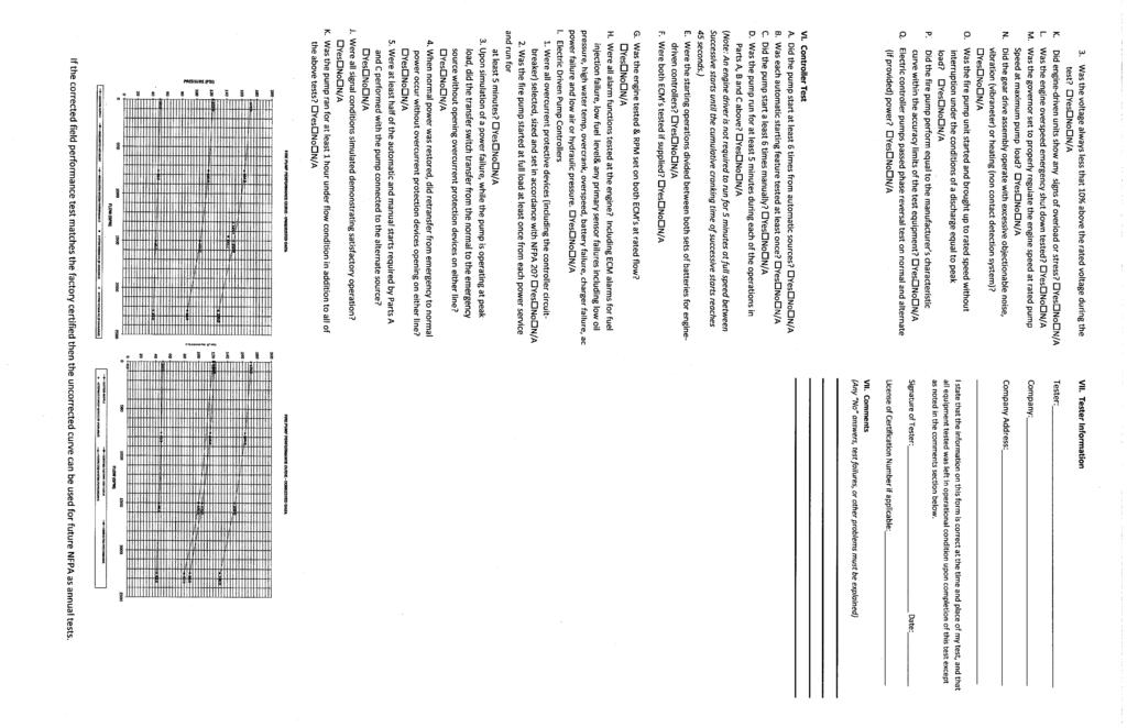
211
 Page 1 of 198 Public Input No. 88-NFPA 20-2013 [ New Section after 3.3.38.10 ] Add New Defination 3.3.28.11 Multiple Stage Multiple Port Pump. A single driver pump with multiple impellers operating in
Resolution: FR-2-NFPA Statement: The new language requires the action completed by NFPA 557 be prepared by a person that is approved.
 Public Input No. 1-NFPA 557-2012 [ New Section after 1.5.3 ] 1.6 Approved Qualifications The design shall be prepared by a person with qualifications acceptable to the AHJ. The term designer is used in
 Page 1 of 46 Public Input No. 17-NFPA 13E-2013 [ New Section after 3.2.4 ] New 3.2.5 Pressure-Reducing Valve. A valve designed for the purpose of reducing the downstream water pressure under both flowing
NFPA 101 SAF-RES PUBLIC COMMENTS
 Page 134 of 195 Public Comment No. 3-NFPA 101-2013 [ Section No. 28.7.6.1 ] 28.7.6.1 New draperies, curtains, and other similar loosely hanging furnishings and decorations shall be flame resistant as demonstrated
Public Comment No. 7-NFPA 30A-2013 [ Section No ]
![Public Comment No. 7-NFPA 30A-2013 [ Section No ]](/thumbs/93/111835478.jpg "Public Comment No. 7-NFPA 30A-2013 [ Section No ]") Page 1 of 13 Public Comment No. 7-NFPA 30A-2013 [ Section No. 6.4.2 ] 6.4.2 Additional Proposed Changes Each pump shall have installed on the discharge side a listed leak detection device that will provide
Page 1 of 13 Public Comment No. 7-NFPA 30A-2013 [ Section No. 6.4.2 ] 6.4.2 Additional Proposed Changes Each pump shall have installed on the discharge side a listed leak detection device that will provide
 Page 1 of 190 Public Input No. 22-NFPA 55-2013 [ Global Input ] Throughout the document, delete ANSI from ANSI/ASME B31.3. Current Text: (multiple locations) ANSI/ASME B31.3 (found in Subsections: 2.3.2
 Page 1 of 37 Public Input No. 1-NFPA 30A-2012 [ New Section after 1.1.2 ] 1.1.3 This code shall not apply to aircraft fuel dispensing facilities. NFPA 30A is commonly referenced, in my opinion, incorrectly,
 Page 1 of 73 Print Reload Page Close Show Cart Public Input No. 13-NFPA 170-2012 [ Global Input ] 3.3.3 Photoluminescent. A type of sign that is self-energized with respect to luminosity and requires no
Public Comment No. 2-NFPA [ Section No ] Statement of Problem and Substantiation for Public Comment. Submitter Information Verification
![Public Comment No. 2-NFPA [ Section No ] Statement of Problem and Substantiation for Public Comment. Submitter Information Verification](/thumbs/94/119830052.jpg "Public Comment No. 2-NFPA [ Section No ] Statement of Problem and Substantiation for Public Comment. Submitter Information Verification") Public Comment No. 2-NFPA 73-2014 [ Section No. 4.1.3 ] 4.1.3 Unused Openings. 4.1.3.1 Unused openings, other than those intended for the operation of equipment, those intended for mounting purposes, or
Public Comment No. 2-NFPA 73-2014 [ Section No. 4.1.3 ] 4.1.3 Unused Openings. 4.1.3.1 Unused openings, other than those intended for the operation of equipment, those intended for mounting purposes, or
Remove the "Exception" text to be consistent with direction provided in the MOS.
 of 37 1/11/2017 7:38 AM Public Input No. 9-NFPA 88A-2015 [ Global Input ] Remove the "Exception" text to be consistent with direction provided in the MOS. The current language in 88A has numerous section
Agenda Technical Committee on Initiating Devices for Fire Alarm and Signaling Systems June 24-25, 2013 Saint Louis, MO
 Agenda Technical Committee on Initiating Devices for Fire Alarm and Signaling Systems June 24-25, 2013 Saint Louis, MO Item No. Subject 13-6-1 Call to Order (8:00 A.M) 13-6-2 Roll Call 13-6-3 Approval
Public Comment No. 22-NFPA [ New Section after 1.4 ] Statement of Problem and Substantiation for Public Comment
![Public Comment No. 22-NFPA [ New Section after 1.4 ] Statement of Problem and Substantiation for Public Comment](/thumbs/96/127508363.jpg "Public Comment No. 22-NFPA [ New Section after 1.4 ] Statement of Problem and Substantiation for Public Comment") of 25 5/14/2015 2:32 PM Public Comment No. 22-NFPA 14-2014 [ New Section after 1.4 ] A.1.4 A.1.4 It is the intent of the Commi ee to recognize that future edi ons of this standard are a further refinement
of 25 5/14/2015 2:32 PM Public Comment No. 22-NFPA 14-2014 [ New Section after 1.4 ] A.1.4 A.1.4 It is the intent of the Commi ee to recognize that future edi ons of this standard are a further refinement
SAF-BCF SECOND REVISIONS WITH STATEMENTS
 Page 196 of 331 32.2.1.3 ] Second Revision No. 153-NFPA 101-2013 [ New Section after 32.2.1.4 Multiple-Level Buildings. For purposes of applying requirements of this chapter that utilize the term level
Page 1 of 5 1/29/2016 4:08 PM. First Correlating Revision No. 3-NFPA [ Section No ] Submitter Information Verification
![Page 1 of 5 1/29/2016 4:08 PM. First Correlating Revision No. 3-NFPA [ Section No ] Submitter Information Verification](/thumbs/87/97398353.jpg "Page 1 of 5 1/29/2016 4:08 PM. First Correlating Revision No. 3-NFPA [ Section No ] Submitter Information Verification") First Correlating Revision No. 3-NFPA 101-2016 [ Section No. 6.1.8.1.1 ] 6.1.8.1.1* Definition One- and Two-Family Dwelling Unit. A building that contains not more than two dwelling units, with independent
First Correlating Revision No. 3-NFPA 101-2016 [ Section No. 6.1.8.1.1 ] 6.1.8.1.1* Definition One- and Two-Family Dwelling Unit. A building that contains not more than two dwelling units, with independent
Technical Committee on Fluidized Bed Boilers
 Technical on Fluidized Bed Boilers AGENDA Web/Teleconference 1. Chair s welcome, call to order, and opening remarks at 1:00 pm EST. 2. Self-Introduction of Members and Guests 3. Approval of Minutes from
TECHNICAL COMMITTEE ON FIRE PUMPS
 TECHNICAL COMMITTEE ON FIRE PUMPS MEMORANDUM TO: FROM: Technical Committee on Fire Pumps Joanne Goyette, on behalf of C. Duffy / R. P. Benedetti DATE: May 2, 2011 SUBJECT: Letter Ballot on Proposals to
Public Comment No. 2-NFPA [ Section No ]
![Public Comment No. 2-NFPA [ Section No ]](/thumbs/93/114140985.jpg "Public Comment No. 2-NFPA [ Section No ]") Page 1 of 13 Public Comment No. 2-NFPA 703-2013 [ Section No. 2.3.1 ] 2.3.1 ASTM Publications. ASTM International, P.O. Box C700, 100 Barr Harbor Drive, West Conshohocken, PA 19428-2959. ASTM D 2898, Standard
Page 1 of 13 Public Comment No. 2-NFPA 703-2013 [ Section No. 2.3.1 ] 2.3.1 ASTM Publications. ASTM International, P.O. Box C700, 100 Barr Harbor Drive, West Conshohocken, PA 19428-2959. ASTM D 2898, Standard
National Fire Protection Association. 1 Batterymarch Park, Quincy, MA Phone: Fax:
 National Fire Protection Association 1 Batterymarch Park, Quincy, MA 02169-7471 Phone: 617-770-3000 Fax: 617-770-0700 www.nfpa.org M E M O R A N D U M TO: FROM: Technical Committee on Standpipes Elena
Second Revision No. 20-NFPA [ Section No. 1.4 ] Supplemental Information. Submitter Information Verification. Committee Statement
![Second Revision No. 20-NFPA [ Section No. 1.4 ] Supplemental Information. Submitter Information Verification. Committee Statement](/thumbs/79/80346596.jpg "Second Revision No. 20-NFPA [ Section No. 1.4 ] Supplemental Information. Submitter Information Verification. Committee Statement") Second Revision No. 20-NFPA 14-2015 [ Section No. 1.4 ] 1.4* Equivalency. Nothing in this standard is intended to prevent the use of systems, methods, or devices of equivalent or superior quality, strength,
Second Revision No. 20-NFPA 14-2015 [ Section No. 1.4 ] 1.4* Equivalency. Nothing in this standard is intended to prevent the use of systems, methods, or devices of equivalent or superior quality, strength,
Public Input No. 16-NFPA [ Section No ] Additional Proposed Changes. Statement of Problem and Substantiation for Public Input
![Public Input No. 16-NFPA [ Section No ] Additional Proposed Changes. Statement of Problem and Substantiation for Public Input](/thumbs/89/99993661.jpg "Public Input No. 16-NFPA [ Section No ] Additional Proposed Changes. Statement of Problem and Substantiation for Public Input") Public Input No. 16-NFPA 211-2014 [ Section No. 2.3.1 ] 2.3.1 ASHRAE Publications. ASHRAE, Inc., 1791 Tullie Circle, NE, Atlanta, GA 30329-2305. ASHRAE Handbook: HVAC Systems and Equipment, 2008 2012.
Public Input No. 16-NFPA 211-2014 [ Section No. 2.3.1 ] 2.3.1 ASHRAE Publications. ASHRAE, Inc., 1791 Tullie Circle, NE, Atlanta, GA 30329-2305. ASHRAE Handbook: HVAC Systems and Equipment, 2008 2012.
Public Input No. 4-NFPA [ Section No. 4.2 ] Statement of Problem and Substantiation for Public Input. Submitter Information Verification
![Public Input No. 4-NFPA [ Section No. 4.2 ] Statement of Problem and Substantiation for Public Input. Submitter Information Verification](/thumbs/95/124845028.jpg "Public Input No. 4-NFPA [ Section No. 4.2 ] Statement of Problem and Substantiation for Public Input. Submitter Information Verification") Public Input No. 4-NFPA 214-2013 [ Section No. 4.2 ] 4.2 * Fire Risk Analysis. A fire risk analysis shall be conducted. The following are some of the factors that shall be considered in determining the
Public Input No. 4-NFPA 214-2013 [ Section No. 4.2 ] 4.2 * Fire Risk Analysis. A fire risk analysis shall be conducted. The following are some of the factors that shall be considered in determining the
Public Input No. 1-NFPA [ Global Input ] Additional Proposed Changes. Statement of Problem and Substantiation for Public Input
![Public Input No. 1-NFPA [ Global Input ] Additional Proposed Changes. Statement of Problem and Substantiation for Public Input](/thumbs/85/92902642.jpg "Public Input No. 1-NFPA [ Global Input ] Additional Proposed Changes. Statement of Problem and Substantiation for Public Input") of 280 2/6/2015 12:06 PM Public Input No. 1-NFPA 58-2013 [ Global Input ] NOTE: This public input originates from Tentative Interim Amendment 58-14-1 (TIA 1079) issued by the Standards Council on August
of 280 2/6/2015 12:06 PM Public Input No. 1-NFPA 58-2013 [ Global Input ] NOTE: This public input originates from Tentative Interim Amendment 58-14-1 (TIA 1079) issued by the Standards Council on August
9/20/2016 2:53 PM. Second Revision No NFPA [ Section No ] Supplemental Information. Submitter Information Verification
![9/20/2016 2:53 PM. Second Revision No NFPA [ Section No ] Supplemental Information. Submitter Information Verification](/thumbs/95/123325533.jpg "9/20/2016 2:53 PM. Second Revision No NFPA [ Section No ] Supplemental Information. Submitter Information Verification") Second Revision No. 2011-NFPA 101-2016 [ Section No. 14.2.2.2.4 ] 14.2.2.2.4* Classroom Door Locking to Prevent Unwanted Entry. Classroom doors shall be permitted to be locked to prevent unwanted entry
Second Revision No. 2011-NFPA 101-2016 [ Section No. 14.2.2.2.4 ] 14.2.2.2.4* Classroom Door Locking to Prevent Unwanted Entry. Classroom doors shall be permitted to be locked to prevent unwanted entry
Public Comment No. 13-NFPA [ Section No ]
![Public Comment No. 13-NFPA [ Section No ]](/thumbs/89/98249010.jpg "Public Comment No. 13-NFPA [ Section No ]") Public Comment No. 13-NFPA 30-2013 [ Section No. 2.3.3 ] 2.3.3 ASTM Publications. ASTM International, 100 Barr Harbor Drive, P.O. Box C700, West Conshohocken, PA 19428-2959. ASTM A 395/A395M, Standard
Public Comment No. 13-NFPA 30-2013 [ Section No. 2.3.3 ] 2.3.3 ASTM Publications. ASTM International, 100 Barr Harbor Drive, P.O. Box C700, West Conshohocken, PA 19428-2959. ASTM A 395/A395M, Standard
Second Revision No. 104-NFPA [ Section No ] Submitter Information Verification. Committee Statement
![Second Revision No. 104-NFPA [ Section No ] Submitter Information Verification. Committee Statement](/thumbs/87/97199093.jpg "Second Revision No. 104-NFPA [ Section No ] Submitter Information Verification. Committee Statement") of 1 9/22/2014 1:38 PM Second Revision No. 104-NFPA 72-2014 [ Section No. 3.3.3 ] 3.3.3 Accessible, Readily (Readily Accessible). Capable of being reached quickly for operation, renewal, or inspections
of 1 9/22/2014 1:38 PM Second Revision No. 104-NFPA 72-2014 [ Section No. 3.3.3 ] 3.3.3 Accessible, Readily (Readily Accessible). Capable of being reached quickly for operation, renewal, or inspections
Throughout standard remove references to the following and replace with the following:
 of 105 1/21/2016 7:49 AM Public Input No. 2-NFPA 30A-2015 [ Global Input ] Throughout standard remove references to the following and replace with the following: (1) ANSI/UL and replace with UL. (2) ANSI
Public Input No. 48-NFPA [ Section No ] Additional Proposed Changes. Statement of Problem and Substantiation for Public Input
![Public Input No. 48-NFPA [ Section No ] Additional Proposed Changes. Statement of Problem and Substantiation for Public Input](/thumbs/89/99821842.jpg "Public Input No. 48-NFPA [ Section No ] Additional Proposed Changes. Statement of Problem and Substantiation for Public Input") of 62 8/4/17, 2:42 PM Public Input No. 48-NFPA 45-2017 [ Section No. 1.1.2 ] 1.1.2 This standard shall apply to all educational laboratory units and instructional laboratory units in which any quantity
of 62 8/4/17, 2:42 PM Public Input No. 48-NFPA 45-2017 [ Section No. 1.1.2 ] 1.1.2 This standard shall apply to all educational laboratory units and instructional laboratory units in which any quantity
Page 1 of 6 10/19/2016 9:49 AM. Public Input No. 4-NFPA [ Section No ] Statement of Problem and Substantiation for Public Input
![Page 1 of 6 10/19/2016 9:49 AM. Public Input No. 4-NFPA [ Section No ] Statement of Problem and Substantiation for Public Input](/thumbs/84/89680532.jpg "Page 1 of 6 10/19/2016 9:49 AM. Public Input No. 4-NFPA [ Section No ] Statement of Problem and Substantiation for Public Input") Public Input No. 4-NFPA 111-2016 [ Section No. 1.1.4.1 ] 1.1.4.1 * This standard shall not cover the following: (1) Application of the SEPSS (2) Distribution wiring (3) Systems having total outputs less
Public Input No. 4-NFPA 111-2016 [ Section No. 1.1.4.1 ] 1.1.4.1 * This standard shall not cover the following: (1) Application of the SEPSS (2) Distribution wiring (3) Systems having total outputs less
TECHNICAL COMMITTEE ON SAFETY AT MOTORSPORTS VENUES. NFPA 610 First Draft Meeting. October 17-18, 2016
 TECHNICAL COMMITTEE ON SAFETY AT MOTORSPORTS VENUES NFPA 610 First Draft Meeting October 17-18, 2016 Westin Kansas City at Crown Center 1 East Pershing Road Kansas City, MO, 64108 Conference Call Access:
Report on First Revisions with Statement June 2014 NFPA 101
 101 FR7040 SAF-MER (36.1.1.4) 36.1.1.4 The provisions of this chapter shall apply to life safety requirements for all new mercantile buildings. Specific requirements shall apply to suboccupancy groups,
Recommended Amendments to the 2015 International Existing Building Code North Central Texas Council of Governments Region
 Recommended Amendments to the 2015 International Existing Building Code North Central Texas Council of Governments Region The following sections, paragraphs, and sentences of the 2015 International Existing
Public Comment No. 16-NFPA 13D-2014 [ Section No ]
![Public Comment No. 16-NFPA 13D-2014 [ Section No ]](/thumbs/90/103297636.jpg "Public Comment No. 16-NFPA 13D-2014 [ Section No ]") of 52 9/22/2014 9:20 AM Public Comment No. 16-NFPA 13D-2014 [ Section No. 2.3.3 ] 2.3.3 ASTM Publications. ASTM International, 100 Barr Harbor Drive, P.O. Box C700, West Conshohocken, PA 19428-2959. ASTM
of 52 9/22/2014 9:20 AM Public Comment No. 16-NFPA 13D-2014 [ Section No. 2.3.3 ] 2.3.3 ASTM Publications. ASTM International, 100 Barr Harbor Drive, P.O. Box C700, West Conshohocken, PA 19428-2959. ASTM
NFPA 37 Public Comment Responses Page 1 of 32
 of 30 11/4/2016 3:05 PM Public Comment No. 6-NFPA 37-2016 [ New Section after 1.6 ] TITLE OF NEW CONTENT Type your content here... 1.7 Pressure Measurement. All pressures expressed in this document are
PROPOSED CODE CHANGES FOR REVIEW BY THE FIRE CODE ACTION COMMITTEE
 PROPOSED CODE CHANGES FOR REVIEW BY THE FIRE CODE ACTION COMMITTEE Developed by the Midwestern Regional Work Group CONTENTS Item 15 Limited area sprinkler systems Item 20 Scope of IFC Ch 7 Item 21 Fire-resistance-rated
The distances in shall be reduced to 130 ft (39.7 m) when manual dry standpipes are installed in open parking garages.
 when manual dry standpipes are installed in open parking garages.") of 123 6/10/2014 9:07 AM First Revision No. 117-NFPA 14-2014 [ Global Input ] 7.3.2.7.5 The distances in 7.3.2.2 shall be reduced to 130 ft (39.7 m) when manual dry standpipes are installed in open parking
of 123 6/10/2014 9:07 AM First Revision No. 117-NFPA 14-2014 [ Global Input ] 7.3.2.7.5 The distances in 7.3.2.2 shall be reduced to 130 ft (39.7 m) when manual dry standpipes are installed in open parking
Delayed Action Closer. Mechanical self-closing device that incorporates an adjustable delay prior to the initiation of closing.
 9/20/2016 2:27 PM Second Revision No. 5006-NFPA 101-2016 [ Section No. 3.3.56 ] 3.3.56 Delayed Action Closer. Self-closing device that incorporates a delay prior to the initiation of closing. Mechanical
TECHNICAL COMMITTEE ON MANUFACTURE OF ORGANIC COATINGS First Draft Meeting Agenda March 19, :00 AM - 5:00 PM EST Web/Teleconference Meeting
 TECHNICAL COMMITTEE ON MANUFACTURE OF ORGANIC COATINGS First Draft Meeting Agenda March 19, 2014 9:00 AM - 5:00 PM EST Web/Teleconference Meeting 1. Welcome. George Seuss, Chair 2. Introductions and Update
Public Input No. 1-NFPA [ Global Input ] Statement of Problem and Substantiation for Public Input. Submitter Information Verification
![Public Input No. 1-NFPA [ Global Input ] Statement of Problem and Substantiation for Public Input. Submitter Information Verification](/thumbs/93/113334715.jpg "Public Input No. 1-NFPA [ Global Input ] Statement of Problem and Substantiation for Public Input. Submitter Information Verification") Public Input No. 1-NFPA 36-2013 [ Global Input ] Revise the document to eliminate the use of "Exception" text. The use of "Exception" text is inconsistent with the Manual of Style. Exception text should
Public Input No. 1-NFPA 36-2013 [ Global Input ] Revise the document to eliminate the use of "Exception" text. The use of "Exception" text is inconsistent with the Manual of Style. Exception text should
SANTA ROSA FIRE DEPARTMENT FIRE PREVENTION BUREAU PLAN REVIEW CHECKLIST
 July 1, 2010 SANTA ROSA FIRE DEPARTMENT FIRE PREVENTION BUREAU PLAN REVIEW CHECKLIST FIRE PUMP REVIEW Address: Permit #: Inspector: Date: Status: Inspector: Date: Status: A-Approved; AC-Approved w/comments;
Report on First Revisions with Statement June 2014 NFPA 101
 101 FR6005 SAF-BCF (32.2.1.1.2) Recommendation: 32.2.1.1.2 Where there are sleeping accommodations for more than 16 residents are provided, the occupancy shall be classified as a large facility in accordance
TECHNICAL COMMITTEE ON STANDPIPES
 TECHNICAL COMMITTEE ON STANDPIPES MEMORANDUM TO: FROM: Technical Committee on Standpipes Elena Carroll, Administrator, Technical Projects DATE: February 28, 2012 SUBJECT: Letter Ballot on NITMAM to NFPA
MEMORANDUM. Technical Committee on Mercantile and Business Occupancies. NFPA 101 Second Draft Technical Committee FINAL Ballot Results (A2017)
") National Fire Protection Association 1 Batterymarch Park, Quincy, MA 02169-7471 Phone: 617-770-3000 Fax: 617-770-0700 www.nfpa.org MEMORANDUM TO: FROM: Technical Committee on Mercantile and Business Occupancies
National Fire Protection Association 1 Batterymarch Park, Quincy, MA 02169-7471 Phone: 617-770-3000 Fax: 617-770-0700 www.nfpa.org MEMORANDUM TO: FROM: Technical Committee on Mercantile and Business Occupancies
 Page 1 of 12 Input No. 62-NFPA 409-2013 [ Section No. 3.3.9 ] 3.3.9 Hangar Building Cluster. A group of buildings with more than one area for the storage and servicing of aircraft and all attached or contiguous
NFPA 101 SAF-AXM PUBLIC COMMENTS
 Page 74 of 195 Public Comment No. 53-NFPA 101-2013 [ New Section after 12.1.4.2 ] TITLE OF NEW CONTENT Type your content here... Aisle Stair. A stair within a seating area of an assembly occupancy that
Agency for Health Care Administration
 Page 1 of 51 FED - K0000 - INITIAL COMMENTS Title INITIAL COMMENTS CFR Type Memo Tag FED - K0130 - MISCELLANEOUS Title MISCELLANEOUS OTHER LSC DEFICIENCY NOT ON 2786 FED - K9999 - FINAL OBSERVATIONS Title
HAWAII ADMINISTRATIVE RULES TITLE 12 DEPARTMENT OF LABOR AND INDUSTRIAL RELATIONS SUBTITLE 7 BOARDS CHAPTER 45.1 STATE FIRE COUNCIL STATE FIRE CODE
 HAWAII ADMINISTRATIVE RULES TITLE 12 DEPARTMENT OF LABOR AND INDUSTRIAL RELATIONS SUBTITLE 7 BOARDS CHAPTER 45.1 STATE FIRE COUNCIL STATE FIRE CODE Subchapter 1 Rules of General Applicability 12-45.1-1
Technical Committee on Multiple Burner Boilers
 Technical Committee on Multiple Burner Boilers AGENDA Salt River Project PERA Club 1 Continential Drive Tempe, AZ January 14-15, 2014 1. Chair s welcome, call to order, and opening remarks at 8:00 a.m.
National Fire Protection Association. 1 Batterymarch Park, Quincy, MA Phone: Fax:
 National Fire Protection Association 1 Batterymarch Park, Quincy, MA 02169-7471 Phone: 617-770-3000 Fax: 617-770-0700 www.nfpa.org M E M O R A N D U M TO: FROM: NFPA Technical Committee on Mercantile and
SANTA ROSA FIRE DEPARTMENT FIRE PREVENTION BUREAU STANDARD
 July 1, 2010 SANTA ROSA FIRE DEPARTMENT FIRE PREVENTION BUREAU STANDARD STANDPIPE SYSTEMS PURPOSE This standard outlines the general requirements for the installation of standpipe systems. CODE REFERENCES
Report on First Revision June 2014 NFPA 101
 101- Log #62 SAF-BSF Final Action: (9.2.3) Submitter: Doug Hohbein, Northcentral Regional Fire Code Development Committee Recommendation: Revise to read: 9.2.3 Commercial Cooking Equipment Operations.
Update all extract references to NFPA documents (including NFPA 72) in Chapter 3 and related annex material to the latest editions.
 in Chapter 3 and related annex material to the latest editions.") 11/16/12 TerraView First Revision No. 15-NFPA 720-2012 [ Global Input ] Update all extract references to NFPA documents (including NFPA 72) in Chapter 3 and related annex material to the latest editions.
11/16/12 TerraView First Revision No. 15-NFPA 720-2012 [ Global Input ] Update all extract references to NFPA documents (including NFPA 72) in Chapter 3 and related annex material to the latest editions.
Public Comment No. 2-NFPA [ Section No ]
![Public Comment No. 2-NFPA [ Section No ]](/thumbs/89/98636858.jpg "Public Comment No. 2-NFPA [ Section No ]") Public Comment No. 2-NFPA 16-2013 [ Section No. 3.3.6 ] 3.3.6* Foam-Water Sprinkler System. A piping network connected to a source of foam concentrate and to a water supply. The piping network is equipped
Public Comment No. 2-NFPA 16-2013 [ Section No. 3.3.6 ] 3.3.6* Foam-Water Sprinkler System. A piping network connected to a source of foam concentrate and to a water supply. The piping network is equipped
Report on First Revision June 2014 NFPA 5000
 5000- Log #12 BLD-BSF Final Action: (55.2 (New) ) NOTE: This proposal appeared as Comment 5000-168 (Log #86) which was held from the A11 ROC on Proposal 5000-239. Submitter: Technical Correlating Committee
Public Input No. 4-NFPA [ Section No ] Statement of Problem and Substantiation for Public Input. Submitter Information Verification
![Public Input No. 4-NFPA [ Section No ] Statement of Problem and Substantiation for Public Input. Submitter Information Verification](/thumbs/82/85532729.jpg "Public Input No. 4-NFPA [ Section No ] Statement of Problem and Substantiation for Public Input. Submitter Information Verification") Public Input No. 4-NFPA 496-2014 [ Section No. 5.2.2 ] 5.2.2 Where When the enclosure has been opened or if the protective gas supply has failed to maintain the required positive pressure, the enclosure
Public Input No. 4-NFPA 496-2014 [ Section No. 5.2.2 ] 5.2.2 Where When the enclosure has been opened or if the protective gas supply has failed to maintain the required positive pressure, the enclosure
M E M O R A N D U M. NFPA Technical Committee on Building Services and Fire Protection Equipment
 M E M O R A N D U M TO: FROM: NFPA Technical Committee on Building Services and Fire Protection Equipment Linda MacKay DATE: November 10, 2009 SUBJECT: NFPA 5000 A2011 ROP Letter Ballot Final Results The
Public Input No. 52-NFPA [ Section No [Excluding any Sub-Sections] ]
![Public Input No. 52-NFPA [ Section No [Excluding any Sub-Sections] ]](/thumbs/81/83983503.jpg "Public Input No. 52-NFPA [ Section No [Excluding any Sub-Sections] ]") 8 of 93 11/6/2015 7:41 AM Public Input No. 52-NFPA 30-2015 [ Section No. 21.2 [Excluding any Sub-Sections] ] For the purpose of this chapter, the term in this section shall have the definitions given.
8 of 93 11/6/2015 7:41 AM Public Input No. 52-NFPA 30-2015 [ Section No. 21.2 [Excluding any Sub-Sections] ] For the purpose of this chapter, the term in this section shall have the definitions given.
Public Comment No. 23-NFPA [ Section No ] Statement of Problem and Substantiation for Public Comment Related Item
![Public Comment No. 23-NFPA [ Section No ] Statement of Problem and Substantiation for Public Comment Related Item](/thumbs/88/116226748.jpg "Public Comment No. 23-NFPA [ Section No ] Statement of Problem and Substantiation for Public Comment Related Item") Public Comment No. 23-NFPA 96-2015 [ Section No. 2.3.1 ] 2.3.1 ASTM Publications. ASTM International, 100 Barr Harbor Drive, P.O. Box C700, West Conshohocken, PA 19428-2959. ASTM E84, Standard Test Method
Public Comment No. 23-NFPA 96-2015 [ Section No. 2.3.1 ] 2.3.1 ASTM Publications. ASTM International, 100 Barr Harbor Drive, P.O. Box C700, West Conshohocken, PA 19428-2959. ASTM E84, Standard Test Method
Second Revision No. 1-NFPA 17A-2016 [ Section No ] Submitter Information Verification. Committee Statement. 1 of 14 6/22/2016 3:15 PM
![Second Revision No. 1-NFPA 17A-2016 [ Section No ] Submitter Information Verification. Committee Statement. 1 of 14 6/22/2016 3:15 PM](/thumbs/91/107420660.jpg "Second Revision No. 1-NFPA 17A-2016 [ Section No ] Submitter Information Verification. Committee Statement. 1 of 14 6/22/2016 3:15 PM") 1 of 14 6/22/2016 3:15 PM Second Revision No. 1-NFPA 17A-2016 [ Section No. 4.3.3 ] 4.3.3 All discharge nozzles shall be provided with caps or other suitable devices to prevent the entrance of grease vapors,
1 of 14 6/22/2016 3:15 PM Second Revision No. 1-NFPA 17A-2016 [ Section No. 4.3.3 ] 4.3.3 All discharge nozzles shall be provided with caps or other suitable devices to prevent the entrance of grease vapors,
MEMORANDUM. NFPA Technical Committee on Solvent Extraction Plants. NFPA 36 First Draft TC FINAL Ballot Results (F2016)
") National Fire Protection Association 1 Batterymarch Park, Quincy, MA 02169-7471 Phone: 617-770-3000 Fax: 617-770-0700 www.nfpa.org MEMORANDUM To: From: NFPA Technical Committee on Solvent Extraction Plants
National Fire Protection Association 1 Batterymarch Park, Quincy, MA 02169-7471 Phone: 617-770-3000 Fax: 617-770-0700 www.nfpa.org MEMORANDUM To: From: NFPA Technical Committee on Solvent Extraction Plants
2015 Recommended Building Code with Amendments. The Executive Committee of the Central Iowa Code Consortium does ordain as follows:
 2015 Recommended with Amendments A resolution of the Central Iowa Code Consortium recommending adoption of the 2015 edition of the International, regulating and governing the conditions and maintenance
Public Input No. 107-NFPA [ Section No ] Statement of Problem and Substantiation for Public Input. Submitter Information Verification
![Public Input No. 107-NFPA [ Section No ] Statement of Problem and Substantiation for Public Input. Submitter Information Verification](/thumbs/92/110051902.jpg "Public Input No. 107-NFPA [ Section No ] Statement of Problem and Substantiation for Public Input. Submitter Information Verification") of 123 7/30/2015 1:48 PM Public Input No. 107-NFPA 96-2014 [ Section No. 1.3.2 ] 1.3.2 The authority having jurisdiction shall determine compliance with this standard and authorize equivalent deviations
of 123 7/30/2015 1:48 PM Public Input No. 107-NFPA 96-2014 [ Section No. 1.3.2 ] 1.3.2 The authority having jurisdiction shall determine compliance with this standard and authorize equivalent deviations
 Page 1 of 15 Second Revision No. 8-NFPA 82-2013 [ Section No. 2.2 ] 2.2 NFPA Publications. National Fire Protection Association, 1 Batterymarch Park, Quincy, MA 02169-7471. NFPA 13, Standard for the Installation
 Page 1 of 19 Committee Input No. 14-NFPA 33-2013 [ Global Input ] Type your content here... Supplemental Information File Name IndoorDraftforCI.docx Description This committee input would be added to new
Committee Input No. 60-NFPA [ Sections , ]
![Committee Input No. 60-NFPA [ Sections , ]](/thumbs/71/66079305.jpg "Committee Input No. 60-NFPA [ Sections , ]") Page 1 of 15 Committee Input No. 60-NFPA 34-2013 [ Sections 3.3.7.1, 3.3.7.2 ] Sections 3.3.7.1, 3.3.7.2 3.3.7.1 Combustible Liquid. A Any liquid that has a closed-cup flash point at or above 100 F (37.8
Page 1 of 15 Committee Input No. 60-NFPA 34-2013 [ Sections 3.3.7.1, 3.3.7.2 ] Sections 3.3.7.1, 3.3.7.2 3.3.7.1 Combustible Liquid. A Any liquid that has a closed-cup flash point at or above 100 F (37.8
Technical Committee on Fundamentals of Combustion Systems Hazards
 Technical Committee on Fundamentals of Combustion Systems Hazards AGENDA Dec 4-6, 2013 Georgia Power Company Headquarters Banquet Room 241 Ralph McGill Blvd Atlanta, GA 1. Chair s welcome, call to order,
INITIAL FIRE SAFETY ASSESSMENT
 INITIAL FIRE SAFETY ASSESSMENT Dhanpur, Chapapur, Kotwali, Comilla COMILLA Chittagong The Alliance for Worker Safety Page 1/16 Introduction to the Report The following report contains a site profile and
First Revision No. 1-NFPA [ Section No ] Submitter Information Verification. Committee Statement 4/15/ :08 AM
![First Revision No. 1-NFPA [ Section No ] Submitter Information Verification. Committee Statement 4/15/ :08 AM](/thumbs/90/103874800.jpg "First Revision No. 1-NFPA [ Section No ] Submitter Information Verification. Committee Statement 4/15/ :08 AM") First Revision No. 1-NFPA 1403-2015 [ Section No. 1.2.1 ] 1.2.1 The purpose of this standard shall be to provide a process for conducting live fire training evolutions to ensure that they are conducted
First Revision No. 1-NFPA 1403-2015 [ Section No. 1.2.1 ] 1.2.1 The purpose of this standard shall be to provide a process for conducting live fire training evolutions to ensure that they are conducted
Public Comment No. 20-NFPA [ Section No ] Statement of Problem and Substantiation for Public Comment Related Item
![Public Comment No. 20-NFPA [ Section No ] Statement of Problem and Substantiation for Public Comment Related Item](/thumbs/75/72069029.jpg "Public Comment No. 20-NFPA [ Section No ] Statement of Problem and Substantiation for Public Comment Related Item") of 27 9/2/2014 9:27 AM Public Comment No. 20-NFPA 24-2014 [ Section No. 2.3.2 ] 2.3.2 ASTM Publications. ASTM International, 100 Barr Harbor Drive, P.O. Box C700, West Conshohocken, PA 19428-2959. ASTM
of 27 9/2/2014 9:27 AM Public Comment No. 20-NFPA 24-2014 [ Section No. 2.3.2 ] 2.3.2 ASTM Publications. ASTM International, 100 Barr Harbor Drive, P.O. Box C700, West Conshohocken, PA 19428-2959. ASTM
WORKING DRAFT OF COMMITTEE MEETING OUTPUT
 WORKING DRAFT OF COMMITTEE MEETING OUTPUT CONTENT NOT FINAL SUBJECT TO REVISION PRIOR TO LETTER BALLOT AND PUBLICATION OF SECOND DRAFT REPORT Document: NFPA 221 Revision Cycle: A2014 Meeting Date: 5/20/2013
Module 3. Water-Based Suppression Systems (WBSS) Part II: Highlights of Code Requirements
 Part II: Highlights of Code Requirements") Module 3 Water-Based Suppression Systems (WBSS) Part II: Highlights of Code Requirements 1 WATER-BASED SUPPRESSION SYSTEMS-PART TWO This module covers: 1. Ohio Building Code requirements and when and why
Module 3 Water-Based Suppression Systems (WBSS) Part II: Highlights of Code Requirements 1 WATER-BASED SUPPRESSION SYSTEMS-PART TWO This module covers: 1. Ohio Building Code requirements and when and why
First Revision No. 49-NFPA 17A-2015 [ Detail ] Submitter Information Verification. Committee Statement 7/30/2015 1:35 PM
![First Revision No. 49-NFPA 17A-2015 [ Detail ] Submitter Information Verification. Committee Statement 7/30/2015 1:35 PM](/thumbs/85/92270546.jpg "First Revision No. 49-NFPA 17A-2015 [ Detail ] Submitter Information Verification. Committee Statement 7/30/2015 1:35 PM") of 25 7/30/2015 1:35 PM First Revision No. 49-NFPA 17A-2015 [ Detail ] Make the following change to 5.2.1.10.2: 5.2.1.10.2* The manual actuation device shall clearly identify the hazard protected and provide
of 25 7/30/2015 1:35 PM First Revision No. 49-NFPA 17A-2015 [ Detail ] Make the following change to 5.2.1.10.2: 5.2.1.10.2* The manual actuation device shall clearly identify the hazard protected and provide
9/23/ :47 AM. Second Revision No NFPA [ New Section after ] Submitter Information Verification. Committee Statement
![9/23/ :47 AM. Second Revision No NFPA [ New Section after ] Submitter Information Verification. Committee Statement](/thumbs/89/99218443.jpg "9/23/ :47 AM. Second Revision No NFPA [ New Section after ] Submitter Information Verification. Committee Statement") Second Revision No. 5501-NFPA 5000-2016 [ New Section after 29.2.1.2 ] 29.2.1.3 Bathtubs, bathtub-shower combinations, and nonemergency showers shall be provided with grab bars in accordance with the provisions
Second Revision No. 5501-NFPA 5000-2016 [ New Section after 29.2.1.2 ] 29.2.1.3 Bathtubs, bathtub-shower combinations, and nonemergency showers shall be provided with grab bars in accordance with the provisions
Single Room Occupancy Hotel Safety & Stabilization Task Force
 Page 1 of 6 Graphics Version Skip to Content Single Room Occupancy Hotel Safety & Stabilization Task Force sfgov residents business government visitors online serviceshelp Single Room Occupancy (SRO) Hotel
Committee Input No NFPA [ Global Input ] Submitter Information Verification. Committee Statement. 1 of /20/ :02 AM
![Committee Input No NFPA [ Global Input ] Submitter Information Verification. Committee Statement. 1 of /20/ :02 AM](/thumbs/75/72631987.jpg "Committee Input No NFPA [ Global Input ] Submitter Information Verification. Committee Statement. 1 of /20/ :02 AM") 1 of 213 10/20/2016 11:02 AM Committee Input No. 2505-NFPA 72-2016 [ Global Input ] Change the term visible to visual where appropriate Submitter Information Verification Submitter Full Name: SIG-NAS Organization:
1 of 213 10/20/2016 11:02 AM Committee Input No. 2505-NFPA 72-2016 [ Global Input ] Change the term visible to visual where appropriate Submitter Information Verification Submitter Full Name: SIG-NAS Organization:
Changes in NFPA
 Changes in NFPA 72-2002 2002 Oregon Fire Code Committee November 25, 2003 Michael B. Baker, SET Automatic Fire Alarm Association MikeBaker@afaa.org 2003 Michael B. Baker 1 Table of Contents 1. Administration
CLARK COUNTY FIRE DEPARTMENT Fire Prevention Bureau
 CLARK COUNTY FIRE DEPARTMENT Fire Prevention Bureau 575 E. Flamingo Road, Las Vegas, NV 89119 (702) 455-7316 FAX (702) 455-7347 Permit Type: 105.7.13 Control Number: A.0 Effective Date: 11/15/11 TITLE:
Alarm. A warning of danger. An indication of the existence of a condition that requires immediate action. (SIG-FUN)
") 4 of 326 11/21/2013 1:03 PM First Revision No. 161-NFPA 72-2013 [ Section No. 3.3.11 ] 3.3.11 Alarm. A warning of danger. An indication of the existence of a condition that requires immediate action. (SIG-FUN)
4 of 326 11/21/2013 1:03 PM First Revision No. 161-NFPA 72-2013 [ Section No. 3.3.11 ] 3.3.11 Alarm. A warning of danger. An indication of the existence of a condition that requires immediate action. (SIG-FUN)
Public Input No. 11-NFPA [ Global Input ] Additional Proposed Changes. Statement of Problem and Substantiation for Public Input
![Public Input No. 11-NFPA [ Global Input ] Additional Proposed Changes. Statement of Problem and Substantiation for Public Input](/thumbs/94/121024521.jpg "Public Input No. 11-NFPA [ Global Input ] Additional Proposed Changes. Statement of Problem and Substantiation for Public Input") of 159 6/10/2014 8:52 AM Public Input No. 11-NFPA 14-2013 [ Global Input ] Include the provision of new design proposal in the code for Fire water system. Additional Proposed Changes File Name NFPA_Public_Input_Form.pdf
of 159 6/10/2014 8:52 AM Public Input No. 11-NFPA 14-2013 [ Global Input ] Include the provision of new design proposal in the code for Fire water system. Additional Proposed Changes File Name NFPA_Public_Input_Form.pdf
Emergency Lighting. This is a free 7 page sample. Access the full version online. Irish Standard I.S. 3217:2008
 Irish Standard I.S. 3217:2008 Emergency Lighting NSAI 2008 No copying without NSAI permission except as permitted by copyright law. Incorporating amendments/corrigenda issued since publication: This document
Public Input No. 1-NFPA 99B-2015 [ Section No. 2.3 ] Statement of Problem and Substantiation for Public Input. Related Public Inputs for This Document
![Public Input No. 1-NFPA 99B-2015 [ Section No. 2.3 ] Statement of Problem and Substantiation for Public Input. Related Public Inputs for This Document](/thumbs/72/66518590.jpg "Public Input No. 1-NFPA 99B-2015 [ Section No. 2.3 ] Statement of Problem and Substantiation for Public Input. Related Public Inputs for This Document") 1 of 19 10/21/2015 1:20 PM Public Input No. 1-NFPA 99B-2015 [ Section No. 2.3 ] 2.3 Other Publications. 2.3.1 ASME Publications. American Society of Mechanical Engineers, Three ASME International, Two
1 of 19 10/21/2015 1:20 PM Public Input No. 1-NFPA 99B-2015 [ Section No. 2.3 ] 2.3 Other Publications. 2.3.1 ASME Publications. American Society of Mechanical Engineers, Three ASME International, Two
We strongly urge NFPA not to adopt future fire sprinkler amendments impacting Category B animals to the NFPA 150.
 of 43 12/4/2013 10:17 AM Public Input No. 41-NFPA 150-2013 [ Global Input ] We strongly urge NFPA not to adopt future fire sprinkler amendments impacting Category B animals to the NFPA 150. Additional
Throughout standard remove references to the following and replace with the following:
 of 35 12/3/2015 7:13 AM Public Input No. 1-NFPA 90A-2015 [ Global Input ] Throughout standard remove references to the following and replace with the following: (1) ANSI/UL and replace with UL. (2) ANSI/ASHRAE
Technical Committee on Fluidized Bed Boilers
 Technical Committee on Fluidized Bed Boilers AGENDA NFPA Headquarters 1 Batterymarch Park Quincy, MA 02169 1. Chair s welcome, call to order, and opening remarks at 1:00 pm EST. 2. Self-Introduction of
SECTION GAS-FIRED RADIANT HEATERS
 SECTION 23 55 23 PART 1 - GENERAL 1.1 DESCRIPTION SPEC WRITER NOTES: 1. Use this section only for NCA projects. 2. Delete between // // if not applicable to project. Also delete any other item or paragraph
Technical Committee on Standpipes (SPI-AAA)
") Technical Committee on Standpipes (SPI-AAA) M E M O R A N D U M DATE: February 13, 2014 TO: FROM: Principal and Alternate Members of the Technical Committee on Standpipes (SPI-AAA) Chad Duffy, NFPA Staff
Technical Committee on Standpipes (SPI-AAA) M E M O R A N D U M DATE: February 13, 2014 TO: FROM: Principal and Alternate Members of the Technical Committee on Standpipes (SPI-AAA) Chad Duffy, NFPA Staff
9/23/ :20 AM. Second Revision No NFPA [ Section No ] Supplemental Information. Submitter Information Verification
![9/23/ :20 AM. Second Revision No NFPA [ Section No ] Supplemental Information. Submitter Information Verification](/thumbs/95/123325589.jpg "9/23/ :20 AM. Second Revision No NFPA [ Section No ] Supplemental Information. Submitter Information Verification") of 4 9/23/2016 10:20 AM Second Revision No. 6501-NFPA 5000-2016 [ Section No. 17.2.2.2.4 ] 17.2.2.2.4* Classroom Door Locking to Prevent Unwanted Entry. Classroom doors shall be permitted to be locked
of 4 9/23/2016 10:20 AM Second Revision No. 6501-NFPA 5000-2016 [ Section No. 17.2.2.2.4 ] 17.2.2.2.4* Classroom Door Locking to Prevent Unwanted Entry. Classroom doors shall be permitted to be locked
First Revision No. 15-NFPA [ Chapter 2 ]
![First Revision No. 15-NFPA [ Chapter 2 ]](/thumbs/76/73953013.jpg "First Revision No. 15-NFPA [ Chapter 2 ]") Page 1 of 28 First Revision No. 15-NFPA 91-2013 [ Chapter 2 ] Chapter 2 Referenced Publications 2.1 General. The documents or portions thereof listed in this chapter are referenced within this standard
Page 1 of 28 First Revision No. 15-NFPA 91-2013 [ Chapter 2 ] Chapter 2 Referenced Publications 2.1 General. The documents or portions thereof listed in this chapter are referenced within this standard
NFPA Technical Committee on Garages and Parking Structures. NFPA 88A Second Draft Web/Teleconference Meeting
 NFPA Technical Committee on Garages and Parking Structures NFPA 88A Second Draft Web/Teleconference Meeting September 30, 2013 2:00 p.m. 3:30 p.m. EDT AGENDA 1. Call to Order: Call meeting to order by
M E M O R A N D U M. NFPA 5000 A2011 ROP Letter Ballot
 M E M O R A N D U M TO: FROM: NFPA Technical Committee on Building Service and Fire Protection Equipment Gregory Harrington, P.E., Staff Liaison DATE: October 1, 2009 SUBJECT: NFPA 5000 A2011 ROP Letter
MEMORANDUM. Technical Committee on Alternative Approaches to Life Safety. NFPA 101A First Draft Technical Committee FINAL Ballot Results (A2018)
") National Fire Protection Association 1 Batterymarch Park, Quincy, MA 02169-7471 Phone: 617-770-3000 Fax: 617-770-0700 www.nfpa.org MEMORANDUM TO: FROM: Technical Committee on Alternative Approaches to
National Fire Protection Association 1 Batterymarch Park, Quincy, MA 02169-7471 Phone: 617-770-3000 Fax: 617-770-0700 www.nfpa.org MEMORANDUM TO: FROM: Technical Committee on Alternative Approaches to
Meeting Agenda Technical Committee on Fire Service Occupational Safety and Health January 8 th -10 th, 2013 San Diego, Ca.
 Meeting Agenda Technical Committee on Fire Service Occupational Safety and Health January 8 th -10 th, 2013 San Diego, Ca. I. Welcome and call to order of the TC by the Chair at 8am. II. Introductions-
Delayed Action Closer. Mechanical self-closing device that incorporates an adjustable delay prior to the initiation of closing.
 Second Revision No. 5006-NFPA 101-2016 [ Section No. 3.3.56 ] 3.3.56 Delayed Action Closer. Self-closing device that incorporates a delay prior to the initiation of closing. Mechanical self-closing device
Life Safety - Means of Egress/Exits NFPA 101
 Life Safety - Means of Egress/Exits NFPA 101 Properly designed exits provide a safe path of escape from a fire or other emergency environment. The means of egress (exits) should be arranged to permit all
First Revision No. 158-NFPA [ Global Input ] Submitter Information Verification. Committee Statement
![First Revision No. 158-NFPA [ Global Input ] Submitter Information Verification. Committee Statement](/thumbs/82/85532588.jpg "First Revision No. 158-NFPA [ Global Input ] Submitter Information Verification. Committee Statement") of 326 11/21/2013 1:03 PM First Revision No. 158-NFPA 72-2013 [ Global Input ] Revise 2.3.1 to update UL 864 to "2003, revised 2012" and upate ANSI/ASME A17 to 2013. Submittal Date: Wed Sep 11 11:08:52
of 326 11/21/2013 1:03 PM First Revision No. 158-NFPA 72-2013 [ Global Input ] Revise 2.3.1 to update UL 864 to "2003, revised 2012" and upate ANSI/ASME A17 to 2013. Submittal Date: Wed Sep 11 11:08:52
Second Revision No. 1-NFPA [ Section No. 2.2 ] Submitter Information Verification. Committee Statement
![Second Revision No. 1-NFPA [ Section No. 2.2 ] Submitter Information Verification. Committee Statement](/thumbs/76/73730261.jpg "Second Revision No. 1-NFPA [ Section No. 2.2 ] Submitter Information Verification. Committee Statement") Second Revision No. 1-NFPA 1410-2014 [ Section No. 2.2 ] 2.2 NFPA Publications. National Fire Protection Association, 1 Batterymarch Park, Quincy, MA 02169-7471. NFPA 1500, Standard on Fire Department
Second Revision No. 1-NFPA 1410-2014 [ Section No. 2.2 ] 2.2 NFPA Publications. National Fire Protection Association, 1 Batterymarch Park, Quincy, MA 02169-7471. NFPA 1500, Standard on Fire Department
1 Batterymarch Park, Quincy, MA Phone: Fax: M E M O R A N D U M
 National Fire Protection Association 1 Batterymarch Park, Quincy, MA 02169-7471 Phone: 617-770-3000 Fax: 617-770-0700 www.nfpa.org M E M O R A N D U M TO: FROM: NFPA Technical Committee on Fire Pumps Patti
First Revision No NFPA [ Global Input ] Submitter Information Verification. Committee Statement
![First Revision No NFPA [ Global Input ] Submitter Information Verification. Committee Statement](/thumbs/80/80445947.jpg "First Revision No NFPA [ Global Input ] Submitter Information Verification. Committee Statement") of 43 10/20/2015 4:02 PM First Revision No. 2035-NFPA 101-2015 [ Global Input ] To 14.3.4.4.1, add an item (4) to read: (4) Carbon monoxide detectors shall be installed centrally located within occupiable
of 43 10/20/2015 4:02 PM First Revision No. 2035-NFPA 101-2015 [ Global Input ] To 14.3.4.4.1, add an item (4) to read: (4) Carbon monoxide detectors shall be installed centrally located within occupiable
Agency for Health Care Administration
 Page 1 of 92 FED - K0000 - INITIAL COMMENTS Title INITIAL COMMENTS Type Memo Tag FED - K9999 - FINAL OBSERVATIONS Title FINAL OBSERVATIONS Type Memo Tag FED - KA100 - General Requirements - Other Title
INITIAL FIRE SAFETY ASSESSMENT - EXPANSION
 INITIAL FIRE SAFETY ASSESSMENT - EXPANSION Factory Plot 47-52 & 68-73, KEPZ North Patenga Chittagong Chittagong 06 Mar 2017 The Alliance for Bangladesh Worker Safety Page 1/23 06 Mar 2017 Introduction
National Fire Protection Association. 1 Batterymarch Park, Quincy, MA Phone: Fax:
 National Fire Protection Association 1 Batterymarch Park, Quincy, MA 02169-7471 Phone: 617-770-3000 Fax: 617-770-0700 www.nfpa.org MEMORANDUM TO: FROM: Technical Committee on Residential Occupancies Kelly