MANUAL FOR PROFORT GSM/LAN DEVICES Ver MANUAL FOR PROFORT GSM/LAN DEVICES 3
|
|
|
- Maximilian Barber
- 5 years ago
- Views:
Transcription
1 MANUAL FOR PROFORT GSM/LAN DEVICES 1 MANUAL FOR PROFORT GSM/LAN DEVICES SPECIFICATIONS FUNCTIONS DESCRIPTION SYSTEM ILLUSTRATION 10 2 MOUNTING PREPARE THE UNIT ELECTRIC MOUNTING INSTALLING A SIM CARD (DOES NOT APPLY FOR UNIT 2) CONNECT THE UNIT (DOES NOT APPLY FOR UNIT 2) CONNECT LAN (ONLY APPLIES FOR UNIT 2) 17 3 PREPARING THE PC MINIMUM REQUIREMENTS FOR THE PC FINDING COM NO INSTALLATION OF THE PROFORT PC PROGRAM 21 5 SET-UP ON PC START SET-UP SETTINGS MAIN PAGE TAB: MODEM (M) TAB: INPUTS (I) COMMANDS IN THE TEXT FIELD TAB: OUTPUTS (O) TAB: CALENDAR (C) TAB: WIRELESS (W) COMMAND EXECUTION IN TEXT FIELD TAB: MORE (V) 41 6 SET-UP VIA MASTERVIEW 44 7 SET-UP VIA DISPLAY ACCESS TO THE UNIT ADD NAME ON DISPLAY SETUP SET CLOCK RESET ALARM HANDLING OF DETECTORS AND REPEATERS SET UP A DETECTOR OR REPEATER INTERRUPT WITHOUT UPDATING EDIT DETECTOR INFORMATION DELETE A DETECTOR MONITOR DETECTORS 49 8 USE THE COMMANDS 50 9 SET-UP WITH (SMS/TEXT MESSAGE) COMMANDS PASSWORD AND ID RECEIVERS INPUTS DIGITAL INPUT ANALOGUE INPUT COMMON FOR DIGITAL AND ANALOGUE INPUTS OUTPUTS VOLTAGE WIRELESS DETECTORS MACRO WITH COMMANDS OR INFRARED INTERNET TIME FEATURES AND CLOCK FUNCTIONS SYSTEM MESSAGES AND -ALARMS RESTORE FACTORY SETTINGS OPERATION CONNECTION AND DISCONNECTION OF THE UNIT CONTROL OF RELAY OUTPUTS INTERRUPT FURTHER ALARMS INQUIRIES TO THE UNIT MACRO EXECUTION TEXT TO AND FROM A SERIAL PORT (RS232) PHOTO CAMERA GPS COMMANDS INTERNET 80
2 Manual for Profort GSM/LAN devices 13 VOICE MESSAGES RECORD VOICE MESSAGE DURATION OF VOICE MESSAGES LOG EVENT LOG DATA LOG IR CODES FREQUENTLY ASKED QUESTIONS SCREENSHOTS 92 2
, 4 modules (unit 4), 9 modules (unit 5), Technic (unit 6), Basic (unit 7), Max (unit 7), Piccolo Light (unit 7) and 6 modules (Unit 8).")

3 Manual for Profort GSM/LAN devices 1 MANUAL FOR PROFORT GSM/LAN DEVICES This manual applies to the Profort GSM units of the type IR remote control (unit 1A and B), IR remote control LAN (unit 2), Technic RF (unit 3), 4 modules (unit 4), 9 modules (unit 5), Technic (unit 6), Basic (unit 7), Max (unit 7), Piccolo Light (unit 7) and 6 modules (Unit 8). Since the manual embraces specifications for units you will not need information on, you can see an overview table below and be aware of the specifications and functions of your particular device. 1.1 Specifications SPECIFICATIONS 1A 1B IR remote control Technic RF 4 modules 9 modules Basic IR remote control IR remote control LAN Basic/Max/ Piccolo Light 6 modules Dimension Design Design box Design box Design box Design box Size (mm) Weight (gram) DIN 4 modules DIN 9 modules Design box Waterproof box/design box, Light DIN 6 modules 130x80x25 130x80x25 130x80x25 130x80x25 69x86x57 157x86x57 130x80x25 225x200x75 114x86x57 Power supply Net 12V DC min. 0,5 A (inclusive) Battery ,6 V rechargeable 12 V DC min. 0,5 A (inclusive) 3,6 V rechargeable (inclusive) 5 V DC min. 0,5 A (inclusive) 12 V DC min. 0,5 A (inclusive) 3,6 V rechargeable (inclusive) V AC/DC min. 0,5 A* 3,6 V rechargeable 230 V AC min. 0,1 A V AC/DC min 0,5 A* 9V rechargeable 12 V DC min. 0,5 A (inclusive) 3,6 V rechargeable (inclusive) 1500 (1250, Basic) 230 V AC min. 0,1 A V AC/DC min 0,5 A* 9V rechargeable V AC min. 0,1 A V AC/DC min 0,5 A* 9V rechargeable 10 V/DC Max. 100 Max. 100 Max V 12V 5V 12V 12V outlet ma ma ma Consumption, approx. standby 30 ma 30 ma 30 ma 40 ma 30 ma 30 ma 30 ma 100 ma 30 ma reloading with battery 150 ma 150 ma 150 ma 150 ma 5 W 150 ma 5 W 5 W emergency 2 ma 2 ma 18 ma 2 ma 2 ma operation Emergency with with 30 min. with 30 min. with with battery with battery supply battery battery battery battery *Supply must not be grounded Antenna Internal, external option 30 minutes with battery 30 minutes with battery Exterior Exterior Exterior (2) Inner Inner Exterior Inner Inner 3
4 Manual for Profort GSM/LAN devices Temperature C C C C C C C C C Digital input Max. 1V, 2 ma (GND) Min. 18 V max. 30 V (24 V DC) Close (NC) / open (NO) Gnd/24V DC GND GND GND GND Galvanic separation Analogue input 0-10 V 0/4-20 ma PT100 Profort temperatur e probe As digital input temperature probe temperature probe + 1 temperature probe Profort PTC input Profort PTC input 4 1 Relay output Number of Max. ampere v/ 230 V AC and 35 V DC Analogue output 0-10 V 1 Camera connection Mini USB Communication GSM modem /optional, 3G (min. 2G) Light Ethernet RJ45 Wireless interface (868 MHz) Wireless digital sensor, up to numbers of Wireless analogue sensor, up to numbers of (optional, Basic) Infrared Sender External sender 1 optional 1 optional 1 optional 1 optional 1 optional 1 optional Receiver
 Quick setup available availabl available available on available on available on available on Available CR-ROM on web on web on web web web web web on web Basis setup optional optional optional")
5 Manual for Profort GSM/LAN devices Display built-in (, Basic) Sound Internal audio Siren Memory for voice 90 sec. 90 sec. Profort PC Program RS232 (9 pol.) Quick setup available availabl available available on available on available on available on Available CR-ROM on web on web on web web web web web on web Basis setup optional optional optional optional optional optional optional CR-ROM optional Pro setup optional optional optional optional optional optional optional optional optional 1.2 Functions FUNCTIONS Receivers of alarms Number of Receive as: text messages (dep. on operator) over the Internet calls with DTMF via RS 232 port to a computer SIA-IP protocol voice messages on the display of the unit and RS232 over the Internet ( Basic) Control of outputs Remote control with text messages, Internet, and DTMF Automatic activation by alarm on input (from 10 sec. till 15 min.) Automatic activation by output follows input Predetermined by Not text message and DTMF 5
6 Manual for Profort GSM/LAN devices timer Predetermined by calendar Via macros and commands in text (simple PLCfunctions) Via the Profort web server and app for smartphones Macro Number of For commands 5 5 For IR codes 5 5 USB/AUX connection Camera GPS Temp.-/humidity sensor Security Password Accepted user(s) (up to 25) User password for the display ( Basic) Log Alarm log (events + commands) Climate log (measurements 2 x per hour) Import and export to.csv file Climate log, export IR codes, import and export Programming Profort PC Program via RS 232 or Internet Internet Text messages Display ( Basic) Functions and facilities Alarm Automatic alarm in case of sabotage and power failure (also in disconnected state) Wait for 30 sec. before alarm is triggered (burglary alarm) Also alarm to the latest user Easy to change order of receivers Calls three times to same recipient in case of no response (voice call and DTMF) (unit only have DTMF calls, unit 2 only ) Acknowledgement of alarm by pressing # during the message (the call list will be interrupted) (not unit 2) Input Input for counting: Input 1 for pulse or minutes. Input for level or pulse. Max. 20 Hz and pulse/minutes Variable filter time for inputs: 10 sec. to 64 hours Input 0 for connecting/disconnecting, possibly with message to receiver 6

 Indication of time in log Calendar function: up to 36")
, e.g.")
 or GPRS/Internet and Profort server Surveillance via the Profort web portal and")
 Macros for execution of more commands simultaneously (max.")
 Wireless alarms, temperature and humidity gauges (unit 4 + 5) (cf.")
 Professional. Profort PC Program for monitoring centre (Profort no.")
 External antenna with 2.5 m cable (Profort no.")
7 Manual for Profort GSM/LAN devices Command execution in texts (simple PLC functions) Synchronisation of outputs if change of value and in case of power failure Time Automatic or manual setting of the clock Time-based connection/disconnection Timer function (with repeat) Control of status messages Status with intervals of minutes, daily, or weekly (Wednesday) Indication of time in log Calendar function: up to 36 activities by date/daily/weekly More Division of alarms into eight zones (areas), e.g. different for open and close Pre-programmed IR codes for heat pumps (not unit 5) Set-up with PC program via RS232 (not unit 1A) or GPRS/Internet and Profort server Surveillance via the Profort web portal and Android/iPhone app/windows WEB Data communication e.g. with PLC via RS 232 (not unit 1A) Macros for execution of more commands simultaneously (max. 10) Scaling of analogue inputs for relevant measurement (0-10V/4-20mA) Some examples of accessories: Temperature probe (Profort no ) Wireless alarms, temperature and humidity gauges (unit 4 + 5) (cf. Profort product catalogue) RS 485 module for extern recipients (unit 5 and 7) (Profort no ) Professional. Profort PC Program for monitoring centre (Profort no ) Disc antenna (Profort no ) Basic. Advanced Profort PC Program (Profort no / ) External antenna with 2.5 m cable (Profort no ) 9V rechargeable battery (unit 5-8) (Profort no ) 3,6V rechargeable Li-ion battery (unit 1, 3, 6 and 8) (Profort no ) IR extension, 2m (unit 1, 2 and 8) (Profort no ) Waterproof box IP-65 (unit 4 + 5) (Profort no ) IR gooseneck (unit 1, 2 and 8) (Profort no ) 7

8 Manual for Profort GSM/LAN devices 1.3 Description All devices from Profort a/s can be set up with many parameters e.g. with own alarm texts. The easiest way is to use the enclosed Profort PC Program. Data is transferred from the computer to the device via a cable in the COM port. If the device contains a GSM modem the set-up can also be affected by means of the Internet, text messages or if your model is with display, the programming can be performed directly on the device's display. Unit 1: IR remote control GSM Unit 2: IR remote control LAN Unit 3: Technic RF Unit 4: 4 modules Monitoring and remote control. The device contains GSM modem and can transfer data and alarms via text messages, Internet, DTMF, SIA-IP or cable. The unit is also able to record and play infrared codes. This model comes with power supply and a temperature sensor. The model exists in two versions: with and without external in-/output and internal battery. Monitoring and remote control. The device is connected to a LAN and communicates via the Profort web server. It transfers alarms via the Internet as s. The unit is also able to record and play infrared codes for e.g. air-toair heat pump. This model comes with a 5V power supply and a temperature sensor. The model has 3 inputs and 1 output. For surveillance and remote control of e.g. diesel tanks. The unit contains of a GSM modem and can transfer data and alarms via text message, the Internet, DTMF, SIA-IP or cable. The unit has a built-in module that receives signals from wireless detectors. Monitoring and remote control. The device contains GSM modem and can transfer data and alarms via text messages, , Internet, DTMF, SIA-IP or cable. Unit 5: 9 modules Monitoring and remote control. The device contains GSM modem and transfers data and alarms via text messages, voice message, , Internet, DTMF, SIA-IP or cable 8


9 Manual for Profort GSM/LAN devices Unit 6: Technic Unit 7: Industry Unit 7: Industry Max Unit 7: Piccolo Light Unit 8: 9 modules For monitoring and remote control of e.g. server rooms. The unit comes with GSM modem and is able to transfer data and alarms via text message, the internet, DTMF, SIA- IP or cable. For measuring, monitoring and remote control. It comes with a display (optional) for operation, showing alarms, and log. It can be expanded with a module that receives signals from your wireless detectors. The device contains a GSM modem and is able to transfer data and alarms via SIA-IP, text message, phone call or the Internet. For object protection, surveillance and remote control. The unit comes with a built-in display for showing alarms, operation, log and a module that receives signals from wireless detectors. The unit can transfer data and alarms via SIA-IP, text message, Internet and as call. Piccolo Light is used for object protection, monitoring and remote control. It has a display for alarm display, operation and log as well as a built-in module which receives signals from wireless detectors. The unit is able to transfer data and alarms via text messages, call or the Internet if mounted with a GSM modem. Monitoring and remote control. The device contains GSM modem and transfers data and alarms via text messages, , Internet, DTMF, SIA-IP or cable. 9
10 Manual for Profort GSM/LAN devices 1.4 System illustration 10

11 Mounting 2 MOUNTING The unit may be mounted in a DIN rail, on a wall, or placed on a table. In order to obtain optimal signal conditions, Profort a/s recommends: Mount the unit vertically and high. The higher it is placed, the better the signals get. Do not put the unit behind metal, reinforced concrete, massive stone or granite. 2.1 Prepare the unit Remember to turn off the unit! Lift off the front cover. 2.2 Electric mounting Figure 2-1 Unit 1A, IR remote control Unit 1B, IR remote control 11
12 Mounting Unit 2, IR remote control LAN Unit 3, Technic RF 12
13 Mounting Unit 4, 4 modules Unit 5, 9 modules 13
14 Mounting Unit 6, Technic Unit 7, Basic, Max and Piccolo Light 14
 or closed (NC) by instructions to the unit. All relay outputs are opened before start-up. Mount digital inputs.")

15 Mounting Unit 8, 6 modules Connect all relay outputs and inputs to the unit. Use at least 0.25 Ø - best even bigger. Mount digital outputs. Relay outputs are potential-free relay switch sets that are opened (NO) or closed (NC) by instructions to the unit. All relay outputs are opened before start-up. Mount digital inputs. Digital inputs are activated by connection by either 0V (gnd) or 24 VDC on the inputs (may be changed via set-up in the enclosed PC program or by SMS/text message). When the connection is removed, the inputs are deactivated. The unit is able to send an alarm both when the connection is turned on and when it is removed. Units 1, 2 and 3 can only be activated through gnd. Units 4-9 have both activation via gnd and 24VDC. NB! Input 0 may be used as connection/disconnection (toggle switch or bell switch). Inputs 1, 2 and 3 may be used as pulse counter or hour counter. Mount analog inputs. As default the analogue inputs function as ordinary digital inputs (all DIP - switches off). Units 1 and 2 have a temperature sensor attached to analog inputs. If the inputs are to have an analogue function, the equipment and probes have to be connected between e.g. gnd and Ain1 or between gnd and Ain2. The figure below is an example of four analog inputs. 15
, the DIP switches in the GSM module are to be adjusted as follows: 0-10 V DC: DIP-switch no.")
16 Mounting Figure 2-2 Each analog input has four DIP switches. Setting of inputs to standard equipment (0-10 VDC, 0/4-20 ma, PT100 probe or Profort probe), the DIP switches in the GSM module are to be adjusted as follows: 0-10 V DC: DIP-switch no. 1 on (others off) 0/4-20 ma: DIP-switch no. 2 on (others off) PT100: DIP-switch no. 3 on (others off) Profort probes: DIP-switch no. 4 on (others off) Digital input: All DIP switches off In case an alarm by power failure is wanted, a 9 V rechargeable battery shall be mounted (except for unit 2). In case of poor GSM reception an external antenna may be mounted (except for unit 2): 1. Remove the internal antenna. 2. Drill a hole in the panel for leading-in a cable. 3. Then mount an extra antenna. Button: Button on units 1A, 1B and 3 has the following features: 1. Press down button and connect supply simultaneously. A beep will sound after 7 secs. Hereby unit is programmed to the default settings. 2. Press button in normal operation and a beep will sound after 7 secs. Let go of the button immediately, and macro 1 will be performed. If there is no function behind macro 1, nothing will happen. 3. If button is held down after 7 secs., another beep will sound after 14 secs. Hereby sabotage is activated. 4. If button is pressed briefly in normal operation, then the unit will sound a series of beeps. It is now ready for the encoding of wireless detectors. If an alarm detector is triggered, the unit will reply by beeping fast and then stop beeping. The first detector is hereby activated. 16
 On models with GSM modem you have to install a SIM card. All common SIM cards may be used except for pure 3G cards.")

17 Mounting You can connect several detectors to the unit by repeating the process (Only applicable for figure 3). 2.3 Installing a SIM card (does not apply for unit 2) On models with GSM modem you have to install a SIM card. All common SIM cards may be used except for pure 3G cards. Profort a/s recommends the use of a SIM card with subscription and not a pre-paid card as the latter often has an expiry date after e.g. six months. 1. Choose the SIM card for the unit 2. Insert the SIM card in an ordinary cell phone 3. Check that the card PIN code is 1234 or deactivate it 4. Check if you can call and send a text message to and from the SIM card in the phone 5. Take the SIM card out of the phone and install it in the GSM unit. If necessary, see Figure 2-1 how to face the card remember to reverse the position of the detected metal down towards the print 2.4 Connect the unit (does not apply for unit 2) 1. Check that inputs and relay outputs have been correctly connected. 2. Place the front on the unit again. 3. Connect the unit to its power supply. Wait app. 10 sec. while the GSM modem gets in touch with the GSM network. If the device has a sound source, four 'beeps' are heard, and the red diode starts blinking. After app. 20 sec., the unit is ready. 4. If necessary, send a text message with "1234 OK" to return the GSM signal strength. It should preferably be above 25%. 2.5 Connect LAN (only applies for unit 2) 1. Connect the unit to the Internet: The unit is connected to the computer network of the house with a normal LAN cable. When the unit can access the Internet, it creates automatic connection to the Profort server. 2. Supply the unit with power: Mount the power supply and switch on power for the LAN unit. The red control diode is lit for approx. 20 sec. After that, the control diode will flash with one single flash every other second. It confirms that the LAN unit is ready and functions correctly. 3. Register the unit on the Profort webportal: Register yourself as a user on our homepage Your username is to be found on the label on the back of the unit. The username is, for instance: ID You choose your own password. Type in your address then we can send your password in case you forget it. Press Register. 17
18 Mounting 4. How to register the unit: a. Give the unit a number. b. Give the unit a name. c. Type in GSM number. It is the same as the username on the label. However, WITHOUT the letters ID. d. The PIN code is always e. The operator is filled in in advance. f. Press Register. 5. Activate the IR codes: The unit is now registered and the IR codes for the heat pump need to be activated. Type in the command: mi(space)(producer name). It is important that you remember to put in a space between mi and the name of the unit. If your heat pump is from, e.g. Panasonic, you write Panasonic in producer name. The unit answers OK if everything functions as it should. If the unit answers??, the heat pump is unknown and the functions need to be encoded manually. 6. Place the LAN unit correctly: The heat pump receives infrared signals from the LAN unit in the exact same way as a television receives signals from its remote control. Therefore it is important that the LAN unit is placed so that the heat pump can see the IR codes of the LAN unit. a. Place the LAN unit in visible distance and max 8 metres from the heat pump. Make sure that there is access to both power supply and a computer network for the unit to be connected. b. One of the two IR diodes needs to point towards the heat pump. c. Test the position by checking whether the heat pump reacts when it is activated from the app. As extra equipment you can purchase an IR gooseneck or an IR cable in order to have more options for placing the LAN unit in visibility of the IR receiver of the heat pump. d. When you are sure that your LAN unit is able to communicate with the heat pump, mount it to wall or ceiling. 18
 serial cable or use a USB to RS232 serial converter. If you use a USB cable, the driver of the cable shall be installed according to the guidelines.")
19 Preparing the PC 3 PREPARING THE PC (Does not apply for unit 1A) Turn on the PC. Connect a serial RS232 cable in the computer's COM port or via a USB adaptor. Use a nine-pin (male/female) serial cable or use a USB to RS232 serial converter. If you use a USB cable, the driver of the cable shall be installed according to the guidelines. Then connect the cable to the unit RS232 port. Figure 3-1 Download the PC program from the Profort homepage and type code M30Gu8. Below is shown the connections required in an RS232 cable. Figure 3-2 male female 3.1 Minimum requirements for the PC Windows Screen resolution 1024 x 768 COM-port or USB-port 3.2 Finding COM No. A PC may have several COM ports, and the assignment of COM No. depends on which COM port is used for the set-up. You therefore have to check which COM No. Windows has assigned to the chosen COM port. Find the number of the chosen COM port (here undergone with Windows XP): 19
 > Communications port or USB-to-Serial Comm. Port 5. Read the number of the COM port.")
20 Preparing the PC Figure Select the Start menu on your PC 2. Select Control Panel > System 3. Select the tab Hardware > Device manager 4. Select Ports (COM & LPS) > Communications port or USB-to-Serial Comm. Port 5. Read the number of the COM port. The figure below illustrates that the COM port is 'COM1' when using the communications port, and 'COM3' when using the USB port. Notice that the next time you mount a cable in the same or another COM port, the assigned COM no. may have changed If you use a USB cable, you have to use the same slot in the computer each time. 20


21 Installation of the Profort PC program 4 INSTALLATION OF THE PROFORT PC PROGRAM When the COM number has been identified start the PC program for set-up of the unit. Installation of Profort PC Program on the computer: Figure Insert CD-ROM in the PC or download it from 2. The program starts with a Welcome Centre, where it is possible to choose to see manuals or to install the program. Press the ' Install ' to begin the installation of the Profort PC application. 3. Select the language to be used during installation 4. The installation program suggests closing all other programs on the computer while installing. 5. Windows suggests a location for installing the set-up program. To change this location, press Browse' (cf. Figure 4-2) and select the required folder. 21


22 Installation of the Profort PC program Figure 4-2 Figure Press ' Next > ' and choose whether to perform additional tasks. Press ' Next > ' again. 7. Check that the settings are satisfactory and press the 'install' to begin installation. The installation runs automatically and takes about 20 sec. 8. Select whether Profort PC application is to open at the end of installation by setting a check mark in the 'Launch Profort' and finish installing Profort PC application by clicking 'Finish'. 9. Figure 4-3 is displayed when the application is started the first time if the Profort PC application has been installed previously for example in a previous version. 22 Select 'Yes' if the existing information such as set-up and log has to be transferred to the new installation. Select 'No' if you want to start with a new, blank application. Note that the previous data will be permanently deleted. 10. Enter the product key the window of the product key opens automatically. The product key is written in front of the cover of the CD or see it on The program is ready and you can now set the units up for use. The program opens automatically after entering the product key. Start to define the settings and continue with the set-up for the rest. Do the Quick Setup or select Basic Setup if you have The Profort Basic PC Program.

23 Set-up on PC 5 SET-UP ON PC The description of set-up on the PC is based on the extended set-up with Basis Setup. It is not all areas or points that can be set up in Quick Setup. In the chapter about Quick Setup you can see on the tabs which functions are available here. Each tab is named with a capital letter: An 'M' symbolizes tab Modem, 'I' indicates tab Inputs, 'O' stands for the tab Outputs, C stands for the tab Calendar, 'W' represents the Wireless tab, and 'V' marks the tab More (Various). Headings (highlighted with bold) at each tab are also numbered with a digit, e.g. the area for the information of the device is numbered with M1 under the heading 'Central unit', and 'Setup' = M3 as in the following figure. The points in an area can similarly be referenced to using a lowercase letter. Example The function 'Send message to receivers on connect/disconnect' has the reference M3-a. It can therefore be found on the tab Modem (M) under 'Setup' (3) as the first point (a). As another example the timer is numbered C3. It is thus on the tab 'Calendar' in the area of number three. Figure 5-1 Tab Modem (M) M1 M2 M3 a d 23
. Open Profort PC program. Depending on the program used, Profort PC Program opens with either a main page for Basis Setup or a window for Quick Setup.")

24 Set-up on PC 5.1 Start set-up Make sure that the device is either connected to the RS 232 port or the USB connector on your pc or that it is set up for the Internet (see Chapter for help to the Internet). Open Profort PC program. Depending on the program used, Profort PC Program opens with either a main page for Basis Setup or a window for Quick Setup. The first time you use the program, you must begin by filling in the settings of the application as described in Chapter 5.2. Continue to define the unit as described in Chapter The settings are stored in the flash memory of the unit and kept, in case of power failure. 5.2 Settings 'Options' applies to all entities that are created in the Profort PC application. If you previously have created units in the program or converted the data from a previous version; you only need to fill in the settings if there are any changes. All changes will take effect on all devices created in the program. After entering the product key the Quick Setup opens directly with a window for the settings (Figure 5-3), while Basis Setup displays a main page, as in Figure 5-4. Enter the settings of the unit, in the Basis Setup choose: Project > Options at the top bar in the left corner of the window. A window as shown in Figure 5-2 opens. Figure 5-2 Figure
25 Set-up on PC Fill in the settings Pin code: If the computer is to operate through a GSM modem, you shall enter the PIN code of the Modem SIM card. Otherwise the field shall be empty. Modem/serial com.port: Enter the number of the COM port to which the unit is connected. Only free COM ports are shown. Do you use the Internet to transfer your set-up, it is not necessary to specify the COM port (remember that the GSM device must then be set up to the Internet with text messages (see Chapter 12)). Connection via the Internet: If you want the opportunity to handle the unit online, the 'Connection via the Internet' shall be marked. In the dropdown menu you must choose which web domain to use. Furthermore, the unit shall have activated and set up the wanted access to the Internet. See how in the section GPRS in Chapter 5.9, if you use the PC Program, or in Chapter 12 Internet if you use text messages. Username on the Internet: Enter a user name if you wish to have access to the Internet. This may consist of letters and numbers and can contain up to 16 characters. Symbols, special characters and spaces are not allowed. The user name is to be used when you log onto State com.port: This feature is only active in Professional Profort PC Program Language: Select language Schedule daily backup: This feature is only active in Professional Profort PC Program Finish by pressing 'Ok'. Down to the left in the display is shown whether the connection to the unit has been made. NB! If 'No connection' is shown; a wrong COM port has been shown, the unit has been turned off, or the RS232 cable has a defect. If the text 'Connection to [product name] is now shown, you shall check whether the correct COM port has been selected. 5.3 Main page The main page is displayed only by set-up with Basis Setup. The unit shall be defined on the main page in the square in the upper left corner (Figure 5-4). You may create several units in the Profort PC Program in case you have to handle more at the same time. Here a unit named Demo is created: 25
 and the outbox (list of sent messages). 3. Enter the GSM No. of the unit (if any). The GSM No.")
26 Set-up on PC Figure 5-4 Create the unit in the upper pane of the window: 1. Enter a number of free choices for the unit. 2. Attach a description of the unit (max. 50 characters). The text is shown in the inbox (list of received messages) and the outbox (list of sent messages). 3. Enter the GSM No. of the unit (if any). The GSM No. is the same as the telephone number of the SIM card. 4. Mark the unit by clicking in the field to the left of the unit no. An arrow is shown in the field and the line is highlighted. The set-up is only valid for the unit indicated. The further set-up of the highlighted unit takes place in six steps: Modem (Chapter 5.4), Input (Chapter 5.5), Output (Chapter 5.6), Calendar (Chapter 5.7), Wireless (Chapter 5.8) and More (Chapter 5.9). Press 'Setup' and continue in the new window. Or choose the Quick Setup by pressing Quick Setup. 26
27 Set-up on PC 5.4 Tab: Modem (M) The Modem tab is only to be completed in case the unit has been mounted with a GSM modem (if necessary see specifications in Chapter 1.1). Central Unit (M1) Create the identification information of the unit. Present password: At start-up, the default unit password is The PIN code of the SIM card shall always be 1234 or deactivated in the telephone the first time the unit is installed or a new SIM card is mounted. If you have lost the password, do as follows: Remove the power from the unit, including possible back-up battery Insert the SIM card in a mobile phone and change the PIN code to (If a PIN code has been activated in the mobile phone, a PUK code may be necessary). Mount the SIM card in the unit and connect the power. The unit may now be coded by text message with password: GSM Number: The SIM card telephone number is indicated here. It is an optional possibility, but a necessity if the watch function is to be used (e.g. in connection with logging of climate data). New password: Enter a new four digit password. May only contain digits - not letters. The SIM card PIN code will then also be changed. You may also choose to deactivate the password so that it is no longer used: Deactivate the SIM card PIN code in your mobile phone and insert it in the unit again. You may want to look in the mobile phone manual for help with deactivation. ID: Here, a possible ID is entered for the unit, consisting of digits or letters (max. 32 characters). The ID will accompany all alarms. If the unit is to send alarms with SIA-IP, the ID number of the central control shall be used as ID (if needed, see Types of alarm below). NB! The password is used to be able to send commands to the unit. The ID follows the alarm from the unit. If this field is not filled in, the ID will be the same as the password. Receivers (M2) Telephone number: A total of 25 telephone numbers may be stored in the unit. They may receive alarms and/or be approved to operate in the system exclusively. A telephone number can be of max. 15 digits. Country code is not necessary. If you wish to use it, you shall enter +'country code', not 00'country code'. Types of alarm: Alarms may be received either as 'SMS', 'Voice', 'DTMF', or SIA-IP. 27
28 Set-up on PC When 'Voice' is chosen, you shall record a message for the alarm (see Chapter 13). (Voice message is only available for units 5-7.) With DTMF, the modem calls a control centre, for example, and plays a tone sequence. Is it a GSM unit and do you wish to receive the alarm as an , then indicate the number which your telephone operator uses for s, e.g. 200=TDC or TDC affiliates (this works in Denmark). Do you use another phone service provider, contact them for help. By marking the option a new field for the address will appear. The address must not exceed 48 characters. If the unit has a LAN interface alarms can only be sent as s. When is pressed, 999 will appear in place of the phone number. Indicate then the preferred address in the space. If you want the alarm dispatched as a SIA IP protocol for a control centre, this shall be indicated at receiver 1. The IP number and port number of the Centre shall be indicated in the field for telephone number. The two numbers shall be separated by a colon. Do not use spaces, and full stops in the IP number shall be maintained. In order for the control centre to recognize the unit, you get an ID number to be defined as the ID of the GSM unit (ID, see p. 27). It is a prerequisite that an agreement has been made with the control centre, who will also give information on relevant numbers. If several types of alarms are wanted, for example both text messages and voice message, it is necessary to create the same number twice. The receiver may acknowledge alarms with voice message or DTMF tones with #. If a receiver acknowledges, the alarm sequence stops and the following receivers on the list are not disturbed. Without acknowledgement, the alarm sequence continues to the end of the list of receivers. Approve: Indicates which numbers are allowed to change the set-up or for example operate relays. If one or more telephone numbers are marked in the field 'Approve', the unit will only accept SMS and calls from these numbers. Only one choice of either 'approve' or 'type of alarm' per line can be approved. If thereafter the approval shall be revoked, this takes place by deleting the receiver in question. If no numbers are created with approval, everybody may contact the unit. NB! In case of a faulty approved telephone number, this has to be corrected in the set-up. It will be necessary to connect a PC with a cable to contact the unit. Zone: 'Zone' can be used for dividing the alarms in "areas" with specific receivers. An input (see Chapter 5.5) in a certain zone will only place an alarm with receivers in the same zone. If 'Zone' is omitted, all alarms are sent to all receivers. 28
29 Set-up on PC Only one zone may be indicated. If the same telephone number is to be called in case of alarm from, for example, two zones, the actual telephone number shall be created twice. If 'Zone' is blank, alarms are received from all zones. System alarms are attached to zone 0 by default. Send: In case of changes in the set-up, the program automatically marks 'Send'. Thus, information on updating of the unit is sent, when the set-up is finished by pressing the button 'Send/Save'. Setup (M3) Send message to receiver when connect/disconnect (M3-a): Message is sent to receivers in zone blank when the unit is disconnected and connected. Optional. Number of seconds before voice message/dtmf tones are sent: Number of seconds that the unit shall wait before it sends a voice message or DTMF tones. This delay secures that the alarm is not delivered in a possible answering service. Optional. (Only some units have voice message) Select possible order of receivers: Receivers are numbered 1-9 and from 10 and up with the letters A-P. The order in the receiver list may be changed, for example 342A. The unit will first send the message to receiver 3, then 4, 2 and 10 (A). The message will only be sent to the receivers that have been listed in this field. Send alarm to the user who has latest contacted the unit (M3-d): If the option is selected, the alarms are sent from the beginning of the receiver list as well as to the person who has had the latest contact with the unit. Choose whether the latest user shall receive the alarms as text message, as voice message, or both as text and voice message (Voice message is only available for units 5-7.) The function makes it possible for more people to operate the unit and get the relevant messages without being created as receivers. At the same time the users avoid getting alarms when they are not using the unit. At a work place it may for example be different people from day to day who shall activate a unit, and only this person benefits from receiving alarms. 5.5 Tab: Inputs (I) The table in Chapter 1.1 shows how many inputs your device has. Digital inputs (I1) Text when input...: Instead of default texts, you may create user-defined texts that are shown on change of state on inputs. The text may be defined for opened and for closed state. The following commands may be sent as SMS/ text message (max. 64 characters). The SMS will be sent in case of alarm (when the state of an input is changed). 29
30 Set-up on PC If you only want an alarm at 'opened' or 'closed', text is only entered in the field for the wanted function. Furthermore, either 'Text' or 'ID + Text' shall be selected in 'Only send alarm if text has been created' under 'Setup' at the bottom of the tab. If the unit has not been coded with user-defined texts, standard messages are sent with alarm: Sx: Close input x (e.g. x = 0-7 if the device has eight digital inputs, x = zero, if the device has one digital input) Bx: Open at input x Zone: Filter: Wait: 'Zone' is optional and may be used to organise alarms in up to eight areas. Alarms in zone 1 are for example only sent to receivers in zone 1. (Remember also to indicate the zone in the call list, see Chapter 5.4, Tab: Modem). If a zone with no corresponding receiver is indicated, no alarm will be sent. Is used where an input only has to control a relay, e.g. a siren. The eight relay outputs follow the zone, i.e. the eight inputs may be put in certain zones that each operates the corresponding relay output. The zone organisation takes place by indicating a digit in the zone field. When working with zones, the central unit reacts by distributing all relay inputs on outputs. NB! The central unit distributes all inputs in zones, i.e. relay 0 is zone 0, relay 1 is zone 1, etc. This means that you cannot move the relays around (see Figure 5-6). If 'Filter' has been selected, the alarm will only be sent where the change of state has been stable during the filter time. Superfluous states lasting only an insignificant number of sec. are discarded and will not produce an alarm. Is used e.g. when a float in a pump well is settling down so that only one alarm is sent. 'Filter' cannot be used together with 'Wait'. If you want the unit to wait half a minute before releasing an alarm, you shall mark 'Wait'. Personnel may then, for example, be able to get out of an alarm area after connection. Send: See 'Send page 29. Analogue ports (I2) (Unit 1 only has a built-in temperature sensor and not a dedicated analogue input). The unit can read analogue values on the analogue inputs (e.g. Ain1). The outputs can be controlled as a reaction on the reading. They can be attached to technical equipment for measuring of an exact value, e.g. temperature. Type: Measurement equipment is chosen (0-10 V, 0/4-20 ma, PT 100, Profort ). Unit 1 does not have an analogue input but instead a built-in temperature sensor. Therefore it must always be set to Profort Is pre-programmed from the factory. 30
31 Set-up on PC If the type field is not completed, the analogue inputs work as digital. Scale min.: + Scale max Point 1: + Point 2 For 0-10 V and 0/4-20 ma you define yourself the wanted values for Volt and Milliampere (from -999 to +999). Decimal places are not allowed. The values for the other measuring equipment are indicated with fixed intervals that may, however, be changed. Example The values for 0 V and 10 V are to be defined. 'min.' corresponds to 0 V, and 'max.' to 10 V (default). You can e.g. define that -20 C corresponds to 0 V and 60 C to 10 V. Define Point 1 and/or Point 2 as limits for allowed values. If the limit values are passed, an alarm is sent. Set e.g. Point 1 to 0 C and Point 2 to 30 C. If the temperature rises to above or falls below 0 C or above or below 30 C, an alarm is released with either Low, Medium or High text (see below). Low, Medium and High text: Low text is sent when e.g. the temperature falls below the value defined in Point 1. Cf. the example above when the temperature falls below freezing. Medium text is the alarm when the temperature rises above the value in Point 1, e.g. above 0 C, or it falls below the value in Point 2, e.g. below 30 C. High text indicates that the value has risen above the indication in Point 2, e.g. that the temperature is above 30 C. The text in the fields can max. be of 64 characters. If, in the meantime, you wish to be informed of a measurement, e.g. a temperature in a room, you send a request to the unit via SMS text with the command V1 R to ask for input 1, V2 R to ask for input 2, etc.. S/F in %: Indicates a maximum allowed deviation at measurement. Alarms at deviation of the interval. The allowed deviation is indicated in percentage by the scale. It needs to be at least 0,5 %. Note a number between 0,5 and 9,9. A positive number alarms at increase while a negative one alarms at decrease in the measurement. X=0,5,..-9,9. Setup (I3) Input 0 is used for connecting/disconnecting: Select how to change the state of an input. Either 'Level' (level control) where closed is disconnected or 'Pulse' (pulse control). When blank, input 0 functions as normal input. Input 1 is used as counting: If you wish to use input 1 as counter you shall mark whether to count pulses or minutes. In the field at input 1, a limit value may be defined, e.g. 500 in closed text. The unit then automatically sends an SMS and resets when the limit value has been reached. When blank, input 1 functions as a normal input. 31
32 Set-up on PC Filter time: Indicates variable filter time for ports. Under 'Digital inputs' (see previous) is marked which inputs that need the given filter time. Choose from 10 sec. up to 64 hours. Inputs 2 and 3 can be used as pulse counter if the boxes are ticked. Only send the alarm if text is entered: If text has been created on inputs (opened and/or closed) and wireless detectors, an alarm is sent (wireless detectors only with unit 3+7). In case of blank text fields, alarm is discarded. In case of 'ID + Text', state, ID and text is sent. In case of 'Text' only text is sent. The alarm text may be adapted to interface to pager systems or CCTV via the serial port. Only send alarm every 15 minutes: Mark the field if you only want to receive one alarm of the same kind each 15 minutes. If input 1 for example alternates between closed and open, the unit will send an alarm when the input closes and one when it opens. The unit will then first send an alarm again after 15 minutes if input 1 closes or opens. The function applies to alarms of the same kind. This means that e.g. an alarm, when input 2 is opened, starts its own time interval of 15 minutes. This function is for example valuable when a PIR sensor is mounted to the device. Send different voice messages on open and close: If so marked, a voice message can be sent in three seconds when the input is opened and another in three seconds when the input is closed. In case of a blank field, the same voice message is sent for opened and closed state. (Voice message is only available for units 5-7.) Activate digital inputs: The inputs shall be set as either GND or 24 VDC mode. Units 1B-3 only have GND. In GND mode, the input is activated by connection to 0 VDC (GND), and the closed state is achieved. If the connection is removed, an open state is reached. In 24 VDC mode, the input is activated by connection to 24 VDC, and the closed state is achieved. If the connection is removed, an open state is reached Commands in the text field It is possible to enter one or more commands in the text field for digital and analog inputs. By this, both a text message can be sent and a command executed when the state of the input is changed. Commands in the front of the text field carries out the command, also when the unit is disconnected. If commands are put last in the text field, the command will not be carried out in disconnected state. In case of more commands, these are separated by semicolons. Commands start with '<' and end with '>'. Example of a command in a text field 32

: Example 5-3 If a person is to receive both an SMS text and a voice message")

33 Set-up on PC Enter, for example, the command <S1;S2;S3> in order to close relays 1, 2 and 3. Example 5-2 In Example 5-2, the unit will send an alarm with the phrase "ALARM" when input 0 is opened. The command '<S1;S2;S3>' in the end of the text field furthermore causes the unit to close output one, two and three, and that an alarm is sent only when the unit is connected. Example of a duty roster The file inputs may also be used to control a duty roster. In the receiver file the call list itself is first created for the duty roster (cf. Chapter 5.4 Tab: Modem): Example 5-3 If a person is to receive both an SMS text and a voice message, the same telephone number is created twice in the call list, e.g. so Peter has position 1+2 ( ), Jens position 3+4 ( ) and Hans position 5+6 ( ). The order of the call list means that the alarm is sent to Peter, first as SMS and then as voice message. Then to Jens as SMS followed by a voice message, and finally to Hans as SMS and voice message. Day 1, Peter and Hans are on duty. Day 2, Jens and Hans are on duty. Day 3, only Peter is on duty. The following is written in the tab inputs: Example
34 Set-up on PC When input 0 closes, alarms will hereafter only be sent to receiver 1+2 and 5+6 (Peter and Hans). By closing input 1, alarm will be sent to receiver 3+4 and 5+6 (Jens and Hans). By closing input 2, alarm is sent to receiver 1+2 (Peter). The last closed input is valid. If e.g. first input 1 and then input 2 are closed, alarm is then sent to no. 1+2 until a closure takes place at another input. Example of a zone connection To connect a single zone following command is sent to the device: Example 5-1 In Example 5-1, zone 1 is connected when input 0 is opened. In order to connect more zones at one time, the zones in question are entered, separated by semicolon: Example 5-2 In Example 5-2, the zones 1 to 3 are connected when input 0 is opened. It is necessary to repeat 'ON' before each zone. A total of seven zones (Z0-Z7) may be connected. 5.6 Tab: Outputs (O) The table in Chapter 1.1 shows how many and which outputs your device has. Output relays may be controlled or activated manually or at change of state on the inputs. The outputs are as default deactivated. They may be automatically activated in several ways (the example shows a device with four outputs): 1. From 10 sec. to 15 min. or constantly. Output 0-3 follow zone Output follows input. Output 0-3 follow input 0-3 including Ain0-Ain3, but only for inputs where texts have been created. NB: This set-up rules out show connection/disconnection. 3. Output shows connection/disconnection. Output 0-3 show connection and disconnection in zone
35 Set-up on PC 4. Combined alarm and connection/disconnection. Output 0-1 follow zone 0-1. Output 2-3 show connection and disconnection in zone Command in the text box on an entry, for example TEXT <S3> closes output 3 on alarm Relay outputs (O1) Opened: Indicates normal state of relays. If outputs are to close by activation of alarm, 'Opened' is marked. Outputs will then be opened at start-up. Closed: Indicates normal state of relays. If outputs are to open by activation of alarm, 'Closed' is marked. Outputs will then be closed at start-up. Send: See 'Send page 29. Analog output (O2): Enter a value for the voltage at the output (0-10 V). (Only unit 5 has an analog output). Setup (O3) Activate relay output on alarms: Indicates whether output shall activate by alarm and for how long. 10 sec., 20 sec., 40 sec., 1 min., 2 min., 4 min. 8 min., 15 min., infinite, reflects inputs. 'Reflects inputs' means that the outputs reflect the corresponding inputs if a text has been created. A blank field indicates that the outputs do not activate. Figure 5-5 If the alarm comes from an input or wireless detector in zone 0, output 0 is activated; zone 1 activates output 1, etc. Figure 5-5 shows how the outputs follow the inputs when the device contains multiple outputs. In case of text for both analog and digital inputs, the analog inputs will have priority to draw outputs one and two. 35
36 Set-up on PC Relay outputs reflect connected/disconnected: If so marked, the outputs are closed when the unit is connected and open when the unit is disconnected. If this field has not been completed, the relay works as normal. If the outputs are to be closed in disconnected state, 'Closed' is to be marked in the box 'Outputs'. NB! If the outputs are defined to display both alarms and disconnected/connected state the distribution is done by this: outputs 0-3 are meant for alarms from zones 0-3, and outputs 4-7 are meant for showing disconnection/connection of zone 0-3. See examples at Figure 5-6 Figure 5-6 Zone 3 active Zone 2 active Zone 1 active Zone 0 active Alarm, zone 3 Alarm, zone 2 Alarm, zone 1 Alarm, zone 0 Output 7 Output 6 Output 5 Output 4 Output 3 Output 2 Output 1 Output Tab: Calendar (C) Calendar is not included in Quick Setup. Calendar (C1) It is possible to create 36 activities. A connection and a disconnection count as two activities. If you replace an old activity with a new one, the program will delete the old activity before it creates the new. Day Indicate time for execution of command: Daily: all weekdays Monday, Tuesday, Wednesday, Thursday, Friday, Saturday, Sunday: specific weekday Date: specific date, select from calendar window or type in date, e.g. June 23, 2012 = blank : activity deleted Time Hour for execution of command, e.g pm = 0930 Command Command for execution on the chosen hour, e.g. ON, OFF, S0, B0 36
37 Set-up on PC Automatic connect/disconnect (C2) Fill in a time for automatic disconnection and connection of the unit. If only automatic connection is wanted, 'Disconnect' is not filled in. To be indicated with HHMM (HH = hours / MM = minutes, e.g Timer (C3) Interval: Choose between 'Weekly', 'daily', ' No. of 15 minutes' and 'No. of minutes' for how often the timer shall activate. Or mark the blank field to deactivate. As default, the timer is programmed to continue till you stop it. This may take place by selecting the blank field as interval or by means of the command Tx (x = 0-9). T + zero stops the timer while 1-9 indicates the no. of times that the timer shall activate, e.g. it starts twice at T2. Use the command TU if the timer shall again run indefinitely (until deactivation). The command may be sent from the field 'Send command' on the main page, via text on an input, with an SMS text or in-built macro. Time: Commands: Indicates the time of activation of the timer. At 'Weekly' (always Wednesday) and 'Daily' is stated the time with HHMM. At 'No. of 15 minutes' is indicated the number of 15 minutes between activations, e.g for each hour. 'Minutes' is stated with no. of minutes between activation, e.g for each 10 minutes. Enter possible commands for the unit to carry out when the timer activates. If you enter e.g. MA D1;MA A1 the unit will send a status update for digital input 1 (MA D1) as well as a status update for analog input 1 (MA A1) when the timer activates. If the command field is empty when the timer is connected, the unit will send status messages on the state of the inputs. Status messages report from the analog and digital inputs that are text defined. May show closed or opened state, an analog value or number of pulses. The unit will also send a status message on connection of the unit. If a status message is sent from an input with a command in the text field, the unit will also carry out the command in question. 5.8 Tab: Wireless (W) Only applies to units which contain features for wireless units 6, 7 and 8. Wireless is not included in Quick Setup. In the tab Wireless, the set-up concerns the wireless detectors. This goes for i.e. the wanted texts and a series of other functions. If the detector is a temperature or humidity meter, further specification is filled in by pressing the button 'Analog', see Figure
. This may be e.g. name or title of the object. The text can be of max. 64 characters. Zone: It may be indicated which zone (0-7) the detector shall belong to.")
38 Set-up on PC Wireless (W1) Detector No.: The six-digit serial number of the detector. Text when detector is activated: Text to be transferred by alarm and shown in the log. (NB: Compulsory when logging data). This may be e.g. name or title of the object. The text can be of max. 64 characters. Zone: It may be indicated which zone (0-7) the detector shall belong to. Remember in this case to indicate the zone in the receiver list (Chapter 5.4 Tab: Modem). Personal alarm: A personal alarm may via attachment to a zone activate an output. If you e.g. create a personal alarm in zone 2, output 2 will be activated by assistance-pressure, while output 3 starts an attack pressure cf. Table below. Figure 5-7 Table 1 Personal alarm belonging to Assistanc e (short pressure) Attack (Long pressure) Activate s output Zone 0 * * 0 Zone 1 * * 1 Zone 2 * 2 * 3 Zone 3 * * 3 Zone 4 * 4 * 5 Zone 5 * * 5 Zone 6 * 6 * 7 Zone 7 * * 7 38
39 Set-up on PC Lev.: Wait: Analog: Here, the sensitivity of a seismic detector is adjusted. The interval goes from zero, which is not activated, to five or blank, which is the highest sensitivity. Default is five. When marking the field, the unit will wait for 30 seconds before an alarm is forwarded. This makes it possible to disconnect the unit before the alarm is released. When connecting, it similarly takes half a minute before the alarm can be released. When you press the button, a new window turns up for set-up: Type: Action: Ok: Alarm text: Ok text: Select type of sensor Select Alarm/Only log Select normal interval Text at alarm Text at normal state NB: If you wish to log data, the unit telephone number or ID number shall be defined so that the unit can get the time from the network, see Chapter 5.4. Setup (W2) Only send the alarm if text is entered: Blank: Alarm is sent from all available detectors with detector number. Text: Alarm consisting of text is only sent from detectors with text attached. ID + text: Alarm containing text, ID and detector number is only sent from detectors with text attached. The alarm text may be adapted to interface to pager systems or CCTV via the serial port. Detector supervision: Detectors send an ok signal with short intervals to the unit. Thus possible faulty detectors are discovered. In case of blank, detectors are not monitored. Battery low warning: If you mark this field, the unit will receive a warning when the battery in the detector should be replaced. The alarm is shown in the display and saved in the log, but is not sent as text or voice message. If this field is not marked, the battery is not monitored. Only send wireless alarm...: If you use GSM, you may indicate whether wireless detectors shall send alarms each or each 15 minutes. If the field is blank, the unit will send an alarm each minute, if the field has been marked, this will take place each 15 minutes. If you do not use GSM/LAN, the unit will receive an alarm each 6 seconds. This time interval cannot be changed. Sound on alarm from wireless detector: The unit will give a sound signal at alarm. There is no sound signal with blank. Send: See 'Send page
40 Set-up on PC Connect/Disconnect (W3) Connect: Select, if required, connection on zone (0-7). If zone is not filled in, the connection is valid for all zones. Remember, if required, to activate 'Send message to receivers on disconnection/connection ' in tab 'Modem'. Disconnect: Select, if required, zone (0-7). If zone is not filled in, the disconnection is valid for all areas. Remember also to activate 'Send message to receivers on disconnection/connection' in tab 'Modem'. Connect after 8 minutes status (changes): When connecting, the unit sends a status of the detectors after 8 minutes. The unit compares the number 'now' with the number at the time when the unit was last disconnected. The purpose is to secure that the unit registers 'the same' detectors after having been disconnected. (Only applies to units which contain features for wireless detectors). Connect after 8 minutes status (active): When connecting, the unit sends a status of the detectors after 8 minutes. Shows which detectors are active. The purpose is to see which detectors, the unit may see, and which have possibly become defective during the disconnection period. (Only applies to units which contain features for wireless detectors). Display (W4) Enter a separate user password, if required. The user password (four digits) is used to log on from the display. (It only works on devices with display). If 1234 is selected as user password, you only have to press OK on the display to log in. If another password than 1234 is selected, this password always shall be entered before pressing OK. The user password allows limited access to the system. With a user password it is only possible to operate a part of the unit display menu while the password of the unit gives full access. Thereby the unit is protected against unauthorised use Command execution in text field It is also possible to enter one or more commands in the text field for detectors. When activating the detector in question, an alarm will be sent, while the command is carried out. As for commands in the text field for inputs: Commands in the front of the text field carries out the command, also when the unit is disconnected. If commands are put last in the text field, the command will not be carried out when disconnecting. In case of more commands, these are separated by semicolons. Commands start with '<' and end with '>'. E.g.: <S1;S2;S3> to close relays 1, 2 and 3. 40

41 Set-up on PC Figure 5-7 The command N1 replaces receiver no. 1 with the telephone number defined in the text field; here Tab: More (V) Setup (V1) Return command: If marked, an acknowledgement for a sent command is sent to the sender. If the field is not marked, there is no acknowledgement. The unit acknowledges with OK>> + sent command when it knows the commands, and??>> + sent command when the unit does not recognize the sent command. The acknowledgement is delivered to the sender. Send also alarm via cable/internet: If marked, an alarm is sent via cable or the Internet Send also sabotage alarm when unit is disconnected: When so marked, a sabotage alarm is sent, also in case the unit is disconnected. If blank, the sabotage alarm is not sent in disconnected state. Send power alarm: When marking ''Immediately' the text 'Power alarm' is sent right away when the external power supply fails. Hereafter the unit runs for 30 minutes where after it closes down. If the supply returns within 30 minutes the unit will send the default text 'Power Ok' If '30 minutes' is marked, the unit will run for 30 minutes while monitoring whether the supply returns. If this does not happen, the unit sends a power alarm and closes down. When the supply returns, the standard text 'Power Ok' will be sent. Power alarm requires the unit to be mounted with a rechargeable battery. Units 1, 3, 4 and 8 do not close down, but continue till the battery is empty. Activate siren on alarms: You can choose if and for how long the unit shall emit a sound signal on alarm. There is no sound signal with blank. Choose between 10 sec., 20 sec., 40 sec., 1 min., 2 min., 4 min., and 8 min. (Unit 7 only). 41
42 Set-up on PC Create clock in unit: The time in the PC will be transferred to the unit. A clock is used for time stamping the log, automatic connection/disconnection and sending of status messages. It is necessary to set the clock, if you wish to log data. Indicate the unit GSM number/telephone number under Tab: Modem, if the unit shall automatically update the time once a week. Even if no battery is used as backup, the power to the unit may be turned off without losing the time. An internal battery saves the time for half an hour (Only valid for unit 7). Set up new text for default texts (V2) Text: Enter, if required, a new text instead of the different default texts. Zone: Select, if required, a zone (0-7) if the text is to be sent from this specific zone to a specific telephone no. Remember to indicate the zone in the call list (Tab: Inputs). GPRS (V3) Phone service provider: Indicate the Internet access of the unit. Either choose not to use the Internet ( GPRS not used ) or activate access by marking the service provider of your SIM card. If your service provider is not on the list, choose: Not listed. Be aware that the fields regarding the Internet under Files Settings also have to be completed (see page 25, if required). APN, User and Password: APN is short for Access Point Name and indicates how the unit obtains connection to the Internet via your telephone operator. Some telephone operators furthermore require user name and password to create the connection. If you choose a service provider from the list, the program will fill in the fields automatically. Contact your telephone operator to obtain APN, user name and password. Macros (V4) Macro name: A macro can collect one or more commands into one super command. Here you enter a name of your choice of up to 16 characters, e.g. 'Start pump'. If the unit receives an SMS with this text, the instructions entered in the field 'Command' are carried out. It is thus not necessary to remember and enter the normal command. You may create a total of 10 macros (M0-M9). They can be activated through the chosen name in a text message or by a call and DTMF tones. Macros are accepted without password. 42
43 Set-up on PC Commands: Here you indicate the instruction/command or instructions/commands (max. 48 characters) to be attached to the macro name chosen. More commands are separated by semicolon. For example P0;T1 to pulse relay 0 and activate the timer once. Have you named a macro, but not inserted a command in the command field, the IR recording function will be activated when you press Save/Send. Hereafter, the red LED light will flash quickly for 30 sec. or turn off when a valid IR code has been received. IR: Units with build-in IR interface can record (only unit 1 + 2) and play (only unit 1+2+7) infrared signals from e.g. a remote control. In the field IR there must be an infrared code from e.g. a remote control. See more about recording or downloading of IR codes in Chapter 15. Get infrared codes from archive: Have IR codes been downloaded or recorded and then archived, they can be found here. See more about archiving of IR codes in Chapter 15. Send infrared codes to archive: Send IR codes, recorded in the Profort PC Program, to the archive. Press the button and type in the manufacturer and unit of the object that fit the IR codes, e.g. Bosch EPH 6.0 heat pump. Send/Save: Or Execute After finishing the set-up, the information is saved on the PC by pressing the button 'Send/Save' in Basic Setup or Execute in Quick Setup below in the window. Basic Setup transfers everything that is marked with Send the Profort PC Program automatically marks the Send when there is made a change. The Quick Setup transfers the entire set-up to the central unit. Remember that the unit has to have a connection, either serial, via modem or over the Internet. In the bottom left corner of the window shall read: connection to <product name> During the transfer of the set-up, the unit 'beeps' three times if it has a sound source. If the transfer is not successful, this message is shown: "Commands not sent". Please try again. In unit 7 the macro 0-4 can be used for IR codes and macro 5-9 for command execution. 43
44 Set-up via masterview 6 SET-UP VIA MASTERVIEW 44

45 Set-up via display 7 SET-UP VIA DISPLAY (This chapter only applies to units with display). The display works as a touch screen. To begin with you press the MENU button on the screen and you are directed to a keypad on which you need to type a password. In order to return to the standby image, press the ESC (short for ESCAPE) button. The display menus are listed as follows: Figure
46 Set-up via display From the display it is possible to manage e.g. the following: Access to the unit (Chapter 7.1) Add a name on the standby image (Chapter 7.2) Setting up the unit (Chapter 7.3) Resetting alarms (Chapter 7.4) Connection/disconnection of the whole central unit or of each of the 0-7 zones (see Chapter 10.1) Handle detectors and repeaters (Chapter 7.5) Monitoring of detectors (Chapter 7.6) See the latest 256 events and analog measurements in the log (see Chapter 14) 7.1 Access to the unit In order to gain access to the menus of the display, you have to log in using an access code. The password is 1234 by default. Log in 1. Press MENU 2. Enter the password of four digits 3. Press ENT (short for ENTER) In PASSWORD: _ it is not necessary to enter 1234, as the unit already knows the default access code Then skip item two and go directly to pressing ENT. Logout 1. Press MENU 2. Press LOGOUT Change password 1. Press MENU 2. Press PROGRAMMING 3. Enter N xxxx (N+zero, the telephone number of the unit, or if the unit has no SIM card mounted, any digit and new password with four digits) 4. Press ENT and the unit acknowledges by 'beep'ing three times. User password In order to limit the access to the display menu list, you may create password number two (user password). 1. Press MENU 2. Press PROGRAMMING 3. Enter TK xxxx (x = user password with four digits) 4. Press ENT and the unit acknowledges by 'beep'ing three times. 46
47 Set-up via display 7.2 Add name on display When the unit is powered, a standby image is shown and after app. 20 sec. four 'beeps' sound. If the front is not on the unit, a red diode may be seen light up as a sign that the unit is connected and ready. If you want a name on the standby image, for instance the name of the museum in question, it can be added to the display as follows: 1. Press PROGRAMMING 2. In COMMAND, the command LA followed by the new text are entered. Always remember a space after a command. 3. Press ENT and the unit acknowledges by 'beep'ing three times. 7.3 Setup The unit may be set up with various commands. See commands under Chapter Select PROGRAMMING 2. In COMMAND: _ use the keypad to enter the desired command 3. Press ENT and the unit acknowledges by 'beep'ing three times. Example Engage battery check of detector: 1. Press PROGRAMMING 2. In COMMAND: _ enter FE 3. Press ENT and the unit acknowledges by 'beep'ing three times Set clock Set the clock in the unit if you want indications of time or to use functions with time control. The unit may be put off without losing the time. An automatic backup saves the time for half an hour. Also functions without backup battery. 1. Press PROGRAMMING 2. In COMMAND: _ enter as follows: TM yy/mm/dd,hh:mm:ss Example TM 12/06/20,11:00: Reset alarm An alarm may only be reset when you have logged in with a password. 1. Select RESET ALARM When resetting an alarm, a possible siren or other alarm equipment, activated by a relay output, is stopped. You may, however, always stop the siren by pressing the clock in the left corner of the screen. 47
48 Set-up via display If you wish to reset an alarm in the display, send command 1234 RS to the unit. 7.5 Handling of detectors and repeaters From the unit display you may set, edit or delete a detector or repeater via the menu point DETECTORS. For monitoring of wireless detectors, see Chapter 14 Log Set up a detector or repeater 1. Start the detector by placing the battery within. 2. Press DETECTORS in the menu 3. Press ADD Activate alarm from the desired detector. Check that the serial number (six digits) of the activated detector is shown in NO. If this is not the case, repeat the procedure. Enter the information identifying each detector: 4. Enter a possible text in TEXT (max. 57 characters), e.g. a title or location. Text may be deselected by pressing ENT and continuing without writing a text. The page then changes to ZONE. 5. Enter a possible zone (with digits from 0-7). Press ENT to jump to LEVEL. 6. Level is only to be set, if the detector is seismic. The setting is valid for sensitivity and indicated with a digit from 0-5 (0 is lowest and = no sensitivity). If no digit has been noted, the default is five for highest sensitivity. 7. Press ENT to finish set-up of the detector. The central unit acknowledges with three 'beeps', and the information is saved Interrupt without updating Entering of detector information may be interrupted without updating the information. Wrong digits or letters may be corrected by one of two procedures: Or Press ESC. You will return to the display menu without updating the information that you were entering. 5. Go to EDIT where you may edit the detector information Edit detector information Go to EDIT to edit detector information. 1. Press DETECTORS. 2. Press EDIT
49 Set-up via display 3. Choose a detector no. and press it Use the UP and DOWN buttons to change pages, if there are more pages with detectors. 4. Use the keypad to write a text. 5. A detector may be attached to another zone (a zone with digits from 0-7). Press ENT to go to LEVEL. 6. Level for sensitivity of a seismic detector may be changed to a higher or lower sensitivity with a digit from Press ENT to finish editing. The unit acknowledges with three 'beeps', and the information is updated Delete a detector 1. Press DETECTORS in the display menu. 2. Press DELETE 3. Select detector no. Use the UP and DOWN buttons to change page. Press the detector no. The text DELETE NO. YES NO is shown in the display. 4. Press NO to cancel the deletion, or press YES to delete. 5. The unit acknowledges with three 'beeps' and the detector has been deleted. Notice: Only one detector may be deleted at a time. If a detector has been deleted by mistake, the information has to be created again. 7.6 Monitor detectors In the menu item SUPERVISION, all wireless detectors may be monitored. Each time the unit receives an OK signal, an alarm or an error message from a detector, the signal strength and a letter code are shown. The display can max. show 6 at a time. If the unit is set to only send alarm if text has been created, you may only see the text defined detectors. Otherwise, all detectors are shown. The detector is shown in the display with serial no., text, signal strength in percentage and type of alarm (A, I or O): Example MONA LISA 25% A A = ordinary alarm I = installation error O = OK The signal strength (in percentage) tells how powerful the signal strength of the detector is. 49
.")

50 Use the commands 8 USE THE COMMANDS Commands are used to operate and set up the device. Commands can be used for set-up and control through the display of the device, with SMS from a mobile phone, or in the command field at the main page in the Profort PC Program (see Figure 8-1). Commands are also used to operate the device automatically. It is done by telling the unit what to do, for example upon an alarm from input, see examples in Chapters and Commands with Profort PC Program Figure 8-1 All commands sent may be seen in the outbox under Files Outbox: Figure Commands with text messages The unit can also be set up with SMS from a GSM mobile phone if the unit has a GSM modem. The set-up then takes place by means of commands. An SMS command consists of the following content: password of four digits * space *
51 Use the commands command of two characters space parameter as text *) may be omitted if the password is deactivated. NB! Each part of the command must be separated by a space. The text can be of max. 64 characters. Spaces count as characters. Example 1234 A1 PUMP OFF PIN code (1234) + [space] + command (A1) + [space] + text (PUMP [space] OFF) The command may be sent by text message to the unit telephone number. 51
52 Set-up with (SMS/text message) commands 9 SET-UP WITH (SMS/TEXT MESSAGE) COMMANDS Note: all commands appear with the password Replace 1234 with your own password or exclude it, if you have deactivated the password on the SIM card. All commands can also be used in the PC software command field and in the set-up on the Internet. Just skip the password You can find a further description of the features under the explanation of Profort PC Program in Chapter 5. The letter and number in the last column shows to which tab and in which region the content behind the command is described. M1 refers to the tab Modem and area Password and id Phone number of the unit: 1234 N0 xxxxxxxx (N0 = N + zero) Password: 1234 N0 xxxxxxxx yyyy (N0 = N + zero) ID code: 1234 N0 xxxxxxxx yyyy TEXT (N0 = N + zero) User password: (Only units with display) 1234 TK xxxx Defines the phone number of the unit and defines it as N0 (N + zero). xxxxxxxx = the phone number of the unit (the number of the SIM card inside the unit) N0 will be created, regardless if you change the password see following. Some functions depend on the unit telephone number to be defined. Changes existing password to the unit is present password, and yyyy = four digits chosen as new password. xxxxxxxx is the unit telephone number and is at the same time defined as such. Set-up of ID code to the unit. If no ID code has been selected, this is the same as the password. The ID code, here called TEXT, may be digits and letters with max. 32 characters. yyyy = four digits chosen as new password. If you do not want a new one, use the old one (here = 1234). xxxxxxxx is the unit telephone number and is at the same time defined as such. Creates user password. xxxx = access code of your choice of four digits. M1 M1 M1 W TK Deletes user password. 9.2 Receivers Create receiver: 1234 Nx yyyyyyyy Creates alarm receiver no. x to receive alarms as text. x = 1-9 og A-P. yyyyyyyy is the telephone number of the alarm receiver. M2 52
53 Set-up with (SMS/text message) commands 1234 Nx yyyyyyyy # (Only units with voice messages) Notice: The code for the first nine receivers is N1 to N9. Receiver 10 to 25 are named NA, NB, NC, etc. through NP. Creates receiver x to receive alarm by voice message. x = 1-9 and A-P. yyyyyyyy is the alarm receiver phone number Nx yyyyyyyy * Creates receiver x to receive alarm by DTMF tones Nx yyy aaaa@bb.com Creates receiver x to receive alarms by . yyy = the number of your telephone service provider for service, e.g. 200 = TDC (in Denmark). Contact your service provider for help. aaa@bb.com = address (max. 48 characters) 1234 N1 xxx.xxx.xxx.xxx:yyyyy N0 qqqqqqqq 1234 zzzz (N0 = N + zero) Delete receiver: 1234 Nx Creates receiver 1 to send alarm as SIA-IP protocol to a control centre. SIA-IP can only be created on receiver 1. (The first SMS: xxx.xxx.xxx.xxx = IP number of the control centre, yyyyy = port number of the control centre. The two numbers shall be separated by a colon. The second SMS: N0 = N + zero, qqqqqqqq = telephone number of the unit, 1234 = password and new password, zzzz = ID when using the SIA-IP, ID has to be stated by the PSAP). Deletes alarm receiver x. x = 1-9 and A-P. Create receivers in zone: 1234 yx zzzzzzzz Creates alarm receiver x to zone y. y = zone 0-7, x = receiver 1-9 and A-P, zzzzzzzz = telephone number. Remember to create zone on input. Ex.: zzzzzzzz Creates alarm receiver 4 to zone 3 = B zzzzzzzz Creates alarm receiver B (11) to zone 2 = 2B. M2 Approve telephone no.: 1234 Nx yyyyyyyy + Order of numbers: 1234 NR xxx... Ex.: Only telephone number yyyyyyyy can contact the unit.. x = 1-9 and A-P for a receiver. More than one receiver can be approved. Changes the order of numbers in the receiver file (x = 0-9 or A-P). Calls will only be made for the indicated receivers and in the listed order. M2 M3 53
54 Set-up with (SMS/text message) commands 1234 NR 3421A The unit will first send the message to receiver 3, then 4, 2, 1 and 10 (A) NR Deletes changed order of numbers in the receiver file. The unit first sends message to receiver no.. 1, then 2, 3, 4, 5, 6, 7, 8, 9 and A, B, C, D P (default setting). Send alarm to latest user: 1234 K1 Latest user gets alarm by text messages K2 Latest user gets alarm as voice message. (Applies for units with voice message) 1234 K3 Latest user gets alarm both by text messages and as voice message. (Voice message only applies for units with voice message) 1234 K0 (K0 = K + zero) Deactivates Send alarm to latest user. (Default setting) M3 9.3 Inputs Digital Input Create digital input Opened: 1234 Ax TEXT Codes the TEXT shown when input x is open. Max. characters are 64 including spaces. E.g. x = 0-7 if the device has eight digital inputs Ax Deletes TEXT for input x in open state. Closed: 1234 Lx TEXT Codes the TEXT shown when input x is closed Lx Deletes TEXT for input x in closed/open state. Zone: 1234 Ax Zy TEXT Creates text on input x (x = 0-7) in zone y (y = 0-7) when input opens Lx Zy TEXT Creates text on input x (x = 0-7) in zone y (y = 0-7) when input closes. Input for connection/disconnection: (Models with only one digital input can either use the input to connection/disconnection or as counter) Sets input 0 (zero) to be used for disconnection/connection of the system (Level). Closed state indicates disconnection RN 1234 RP Sets input 0 (zero) to be used for disconnection/connection of the system (Pulse) RF Deactivates connection and disconnection on input I1 I1 I1 I3 54
55 Set-up with (SMS/text message) commands Create filter and zone: 1234 Ax Xy TEXT 0 (zero) to ordinary alarm input. Default setting. Creates filter on input x in zone y at opening/breaking x = e.g. 0-7 if the unit has eight inputs y = Lx Xy TEXT Creates filter on input x in zone y at closing/joining x = e.g. 0-7 if the unit has eight inputs y = 0-7 Input 1-3 as counter (Models with only one digital input can either use the input to connection/disconnection or as counter) Pulse count: 1234 C C1 xxxxxx 1234 C2 xxxxxx 1234 C3 xxxxxx Minute count: 1234 C1 M Sets input 1-3 to be used for pulse count. Counter is reset at the same time as this instruction (C1 C3). Activates pulse counting. xxxxxx equals a start value between 0 and Enter e.g. 50, and the count will start at 50 pulses. Sets input 1 to be used for minute count C1 M xxxxxx Activates count of minutes. xxxxxx equals a start value of 0 and Enter e.g. 50, and the alarm will go off after 50 minutes. Alarm input: 1234 C2 F 1234 C3 F Pulse count, limit value and alarm text: Deactivates pulse or minute count and sets input to ordinary alarm input. Default setting. When the pulse meter has been created with "UN" a limit value may be set and an alarm sent if the value is exceeded. The counter is reset after alarm. I3 I3 I3 I L1 xxxxxx 1234 A1 TEXT Sets the alarm limit (xxxxxx = ). Alarm text is sent in case of exceeding the limit Analogue input Scale: 1234 Vx S yyyy zzzz Set up of the scale (yyyy = minimum zzzz = maximum) for 0-10 V and for 0-20 ma. x = e.g. 1-2 if there are two analogue inputs. Min. and max. must be between -999 and 999. Decimal places are not allowed. I2 55
56 Set-up with (SMS/text message) commands Points for the normal interval: 1234 Vx M yyyy zzzz Alarm text: 1234 Vx A TEXT Setting up values for the normal interval (Point 1 and Point 2) on analogue input x. x = e.g. 1-2 if there are two analogue inputs. If the value on the input is greater or smaller than yyyy (Point 1) or greater or smaller than zzzz (Point 2), an alarm is sent. E.g. 0 degrees in yyyy and 30 degrees in zzzz. Low alarm TEXT on analogue input x is sent when the value becomes lower than the value defined in Point 1/yyyy (Vx M yyyy zzzz) Vx L TEXT Medium alarm TEXT on analogue input x is sent when the value becomes higher than the value defined in Point 1/yyyy or lower than the value in Point 2/zzzz (Vx M yyyy zzzz) Vx B TEXT High alarm TEXT on analogue input x is sent when the value becomes higher than the value defined in Point 2/zzzz (Vx M yyyy zzzz). Zone on analogue alarms: 1234 Vx A Zy TEXT Low alarm TEXT on analogue input x is sent to zone y when the value becomes lower than the value defined in Point 1. I2 I2 y = 0-7 if the unit has eight inputs Vx L Zy TEXT Medium alarm TEXT on analogue input x is sent to zone y when the value becomes higher than the value defined in Point 1 or lower than the value in Point 2. y = 0-7 if the unit has eight inputs Vx B Zy TEXT High alarm TEXT on analogue input x is sent to zone y when the value becomes higher than the value defined in Point 2. y = 0-7 if the unit has eight inputs Vx Py Alarm when percentage deviation in the interval, e.g. x = 0-3 if the unit has two analogue inputs. Y = -99 0,5 (negative number with one decimal at the most) to reach the allowed percentage, a level may have to decrease. And -0,5-99 (positive number with one decimal at the most) to reach the allowed percentage, a level may have to increase. Create filter and zone: 1234 Vx A Xy TEXT Low Creates filter on analogue input x in zone y at low, middle and high level. x = e.g. 0-3 if the unit has four analogue inputs y = Vx L Xy TEXT Middle 56
57 Set-up with (SMS/text message) commands 1234 Vx B Xy TEKST High Common for digital and analogue inputs Filter time: 1234 Fx Create filter on input in x time. (x = P-V). 1= 10 sec. (default), 2 = 20 sec., 3 = 30 sec., 4 = 1 min., 5 = 2 min.., 6 = 4 min., 7 = 8 min., 8 = 15 min., 9 = 30 min., P = 1 h(our), Q = 2 h., R = 4 h., S = 8., h = 16 h., U = 32 h..,v = 64 h. I3 Voice message/dtmf (Only for units with voice messages) Alarm voice message or DTMF: 1234 W1 Sets the unit to send voice messages with a collective message of six sec. for each input W2 Sets the unit to be able to send voice messages for both opened and closed state. Three sec. for opened state and three sec. for closed state Xy Indicates number of sec. from the establishment of the telephone connection to the first DTMF tone or voice message is sent. y = 0-9 for number of sec. Default setting = 2. If 0 is used, the unit awaits acknowledgement from the control centre before sending DTMF tone. I3 M3 Commands in text Command in text: 1234 Ax TEXT <COMMAND> A command after the text is executed only when the device is connected. (Here COMMAND is carried out when input x is opened when the unit is connected.) I1 + W Ax <COMMAND> TEXT Commands placed in front of the text are executed even if the device is disconnected. (Here COMMAND is carried out when input x is opened when the device is connected as well as when it is disconnected. Examples: 1234 A1 <MA> ALARM Sends the status of inputs with text when input 1 is opened. Command precedes the alarm text and is performed both when the device is connected and disconnected. I1 + W1 57
58 Set-up with (SMS/text message) commands 1234 A1 GENTAG <TP T 0001> Sends the alarm 'repeat' when input 1 is opened (A1), and set the timer to send status every quarter of an hour (< TP T 0001>). The command is placed after the text and is therefore performed only when the device is connected L1 STOP GENTAG <TP> Stops the alert with the message 'STOP REPEAT' when input 1 closes (L1), and deletes the timer settings (<TP>). Thereby sending the status is stopped. Is only performed when the device is connected. Send alarm Alarm only with text: 1234 CT Only sends alarms which text on input and output has been created. Only entered text is sent CN Only sends alarms which text as well as ID on input and output has been created CF Sends alarms even if text has not been created. (Default setting) Delay on connection/disconnection ( wait ): Delays the alarm for 30 sec. for input x at opening in 1234 Ax Wy TEXT zone y. x = for example 0-7 by eight inputs y = 0-7. Zone 0 = all zones ' blank ' Lx Wy TEXT Delays the alarm for 30 sec. for input x at closing in zone y. x = for example 0-7 by eight inputs y = 0-7. Zone 0 = all zones ' blank '. Pool alarms together (Only valid for use of GSM): 1234 DM Collects alarm messages so that more alarms from same digital input or wireless detector only causes one alarm message each 15 min. (Default setting) I3 I1 I3 58
59 Set-up with (SMS/text message) commands 9.4 Outputs Automatic alarm: 1234 Gx Activates (closes) automatic relay outputs at alarm on inputs, and relay is opened again after x time. x = 1-9 (1 = 10 sec., 2 = 20 sec., 3 = 30 sec., 4 = 1 min, 5 = 2 min, 6 = 4 min, 7 = 8 min, 8 = 15 min og 9 = indefinite. O G0 (G0 = G + zero) Show connection and disconnection: 1234 QN If relay outputs are to be opened, the relays are closed before by activation with the command Sx (x = 0-3 if the unit has four outputs). Does not activate automatic relay output 0 at alarm. Default setting. Sets the output to show the state of zones. Output 0 will close when the system is connected and open when the system is disconnected (default). If no zone has been indicated in the set-up only output 0 is activated. If relay outputs are to be opened, the relays are closed before by activation with the command Sx (x = 0-3 if the unit has four outputs). This is also valid for other outputs if there are more than one QF Relays do not show state of zones. Default setting. O1 O3 Alarm and connection/disconnection: 1234 Gx and 1234 QN Combines activation of outputs at alarm on zones with display of connection/disconnection. O3 Outputs follow inputs: 1234 GA Analogue output: (Only applies to units with analog output) 1234 Ux S yy,y Indicates that outputs follow the corresponding inputs if text has been created. Alarm on analogue input activates relay 1. The command 1234 GA may not be used together with 1234 QN ( Outputs show connection/disconnection ). Set analog output x for a voltage of yy, y volts. x = 0 (zero) when the device has one analogue output. y = 00,0-10, Ux R Returns the voltage at the analogue output x. x = 0 (zero) when the device has one analogue output. O3 O2 59
60 Set-up with (SMS/text message) commands 9.5 Voltage Voltage: 1234 WN 1234 WF Power-saving: Sets inputs to activate at 24 V. Sets inputs to activate at GND (default setting). Unit 4 can be set up to run in power saving mode. The device must be supplied with a battery and disconnected from external power. It must not be associated with a serial cable. In the power saving mode the GSM modem will go into hibernation mode and automatically wake of hibernation for one minute each hour. Alarms from inputs and power failure will be sent at once but the device only responds to commands once every hour DN Activates the power saving mode I DF Disable the power saving mode (default setting) 1234 DB Enables enhanced charging to approx. 4,1 V 1234 DE Deactivates enhanced charging. 9.6 Wireless detectors (Only for units with features for wireless) Create detector Create detector: 1234 DT xxxxxx TEXT Create detector no. xxxxxx with the chosen TEXT (max. 57 characters). Detector no. is shown on the detector DT xxxxxx Deletes text for detector no. xxxxxx. Zone: DT xxxxxx Zy TEXT Alarm only if text: 1234 CT Zy in the beginning of the text, indicate that the input belongs to zone y. y = 0-7 Sets the unit to send created text from detectors CN Sets the unit to send ID, detector no. and created text CF Send alarms, although text is not created. Default Setting 1234 CB Send alarms, although text is not created. Stops if an OK-signal is not received after 30 min. W1 W1 W2 60
61 Set-up with (SMS/text message) commands Await alarm ( wait ): 1234 DT xxxxxx Wz TEXT Time interval for alarms (Only valid for use of GSM): 1234 DM Writing Wz before the text indicates that the alarm from detector no. xxxxxx is only sent after 30 sec. z = 0-7 for zones. Collects alarm messages so that more alarms from same wireless detector only cause one alarm message each 15 min. Also affects digital inputs. Default setting DS Collects alarm messages so that more alarms from same wireless detector only cause one alarm message each min. Sound by alarm: Activates sound signal from the central unit when 1234 HN the wireless detector releases alarm. (Default setting) 1234 HF Deactivates sound signal by activation of wireless detector. W1 W2 W2 Sensitivity: 1234 xxxxxx yz TEXT Writing yx before the text specifies the sensitivity of the wireless seismic detector to be y and that it is connected to zone z. y = is the highest sensitivity and default, and 0 means not activated. z = 0-7 for zones. W1 Monitoring Failures to operate: Creates monitoring of detectors and makes sure 1234 FN that failures to operate are communicated to receiver FF Deactivates monitoring of detectors. (Default setting) Battery: 1234 FB Creates monitoring on low battery level on detectors FE Deactivates monitoring of low battery on detectors. (Default setting) W2 Analog detectors Wireless temperature (first create the detector): 1234 D1 xxxxxx S 0 0 Activates temperature measurement in the climaspot with detector no. xxxxxx. W1 61
62 Set-up with (SMS/text message) commands 1234 D1 xxxxxx S Activates temperature measurement in flexspot D1 xxxxxx M z y Activates temperature alarm (if temperature exceeds the limits for normal interval). z = lowest and y = highest limit temperature in the normal interval D1 xxxxxx M Deactivates temperature alarm. Measurements are now solely used for logging D1 xxxxxx Deletes temperature set-up on detector xxxxxx. Text temperature alarm: Creates TEXT to be shown at temperature alarm D1 xxxxxx A TEXT 1234 D1 xxxxxx L TEXT Creates TEXT to be shown when the temperature is again in the normal interval. W1 Wireless humidity and other analogue measurement (first create the detector): 1234 D2 xxxxxx S 0 0 Activates moisture measurement in the climaspot with detector no. xxxxxx. W D2 xxxxxx S z y Activates moisture and other analogue measurement in flexspot z = minimum value and y = maximum value for analogue measuring equipment, e.g. PT100: x = -248 and y = D2 xxxxxx K y Defines factors for volt and mill amperes V: y = ma: y = D2 xxxxxx K Deletes factors for volt and mill amperes D2 xxxxxx M z y Activates moisture and other analogue alarm (if humidity exceeds the limits for the normal interval). z = lowest and y = highest limit for humidity in the normal interval D2 xxxxxx M Deactivates humidity and other analogue alarm. Measurements are now solely used for logging D2 xxxxxx Deletes the setup for humidity and other analogue measurement on detector xxxxxx. Text humidity and other analogue alarms: 1234 D2 xxxxxx A TEXT Creates TEXT to be shown at humidity and other analogue alarm. W D2 xxxxxx L TEXT Creates TEXT to be shown when humidity or other analogue measurements again are within the normal interval. 62
63 Set-up with (SMS/text message) commands 9.7 Macro with commands or infrared Macro: 1234 Mx TEXT <COMMAND> Registers macro number x with the name TEXT (max. 16 characters) and carries out the command. More commands are separated by semicolon ; without space. x = 0-9 and refers to the macro number. Example 1234 M0 PULSE5 < S0;PS 5;B0 > Creates macro no. zero with the name PULSE5 which draws output 0 for 5 sec Mx TEXT (only units 1 + 2) 1234 NAME 1234 Mx Macro number x (x = 0-9) with the name TEXT is now made ready to receive IR codes from a remote control Note that no commands is being set here. When the device's red diode flashes quickly: turn the remote control towards "IR in" and press with the desired functions for 30 sec. The diode lights up briefly and then flashes normally. Now is macro x saved with an infrared code. Activates the macro named TEXT. The macro will now execute commands or play the IR codes. Macros are accepted without password Deletes macro x (x = 0-9). V4 9.8 Internet See more in Chapter 12. Access: 1234 EH USERNAME 1234 EA USERNAME xxxxxxxx Activates the access to the Internet. To get access to the Internet it is required that N0 (N + zero) has been created: (1234 N ) Activates access to the Internet and creates N0. (xxxxxxxx = phone number of the device) 1234 EH Deactivates the access to the Internet. V EG NAME-OF-APN Defines the APN for the Internet connection. internet as APN is default setting. E.g EG INTERNET 63
64 Set-up with (SMS/text message) commands 1234 EG APN USER PASSWORD Defines the APN, user and password for the Internet connection. Own server: 1234 EI SERVERNAME Sets the device for handling on your own server. TCPSERVERPORT 9.9 Time features and clock functions Time Create clock: 1234 TM Creates automatically the clock in the unit. The unit sends an SMS to itself and uses the actual time. It is required that N0 (N + zero) has been defined: (1234 N ) 1234 TM YY/MM/DD,HH:MM:SS Creates clock in the unit manually. The unit uses the time indicated. Enter year/month/date,hour:minute:second all with two digits TR Returns the time of the unit TF Deletes clock from the unit. V1 Timer and status Timer: 1234 TP x yyyy <zz;zz> Codes the timer to execute command zz and command zz with an interval x at the time yyyy. x = W (for weekly), D (for daily), T (for number of 15 min. intervals) and M (for number of minutes). Indicates the interval of activation of the timer. yyyy = At 'Weekly' (always Wednesday) and 'Daily' is indicated with HHMM (time with hour and minutes). At 'No. of 15 minutes' is indicated the number of 15 minutes between activations, e.g for each hour. 'Minutes' is stated with no. of minutes between activation, e.g for each 10 minutes. C3 zz = command. E.g. MA D0;MA A1 to get status at the digital input zero (MA D0) and the analog input 1(MA A1), respectively. Note: the unit phone number and time need to be defined: 1234 N0 xxxxxxxx 1234 TU Sets the timer to run indefinitely (default) 1234 Tx Codes the timer to activate x times (x = 1-9) 64
65 Set-up with (SMS/text message) commands 1234 T0 (T0 = T + zero) Stops/deactivates the timer 1234 TP Deletes timer settings. Status: 1234 TP x yyyy Sets the timer to only send status. Functions as the timer, but without commands. C3 Time control Automatic connection/disconnection: 1234 TI HHMM hhmm Creation of automatic connection and disconnection of system. First parameter indicates time for connection and second parameter the time for disconnection. Notice that time for disconnection is at your choice TI Deletes settings to automatic connection and disconnection. C2 Time control of relay 1234 IU HHMM hhmm Activates time control of output for an interval. Closes relay 2 at 'HH:MM' and opens at: 'hh:mm'. Remember to define which output you need time controlled (1234 IG x) see below IU HHMM hhmm HHMM hhmm Activates time control of output in two intervals. Remember to define which output you need time controlled (1234 IG x) see below IU Deletes time control of all outputs. Define output for time control: 1234 IG x Defines which output time control applies for. Time control can apply for more than one output at a time. (x = 0-3 if the unit has four outputs. Units with more than four outputs can only use time control on output 0-3) IH x Deletes time control of output x. Calendar Specific date: 1234 TS DDMMYY HHMM <COMMAND;COMMAND> Daily: 1234 TS D HHMM <COMMAND;COMMAND> Execute command(s) on date: ddmmyy, time hhmm. NB: The activity can NOT be deleted automatically. It needs to happen subsequently with: TS ddmmyy hhmm when the activity is executed. Execute command(s) every day at hhmm (time). Example C1 65
66 Set-up with (SMS/text message) commands Weekly: 1234 TS M HHMM <COMMAND;COMMAND> 1234 TS T HHMM <COMMAND;COMMAND> 1234 TS O HHMM <COMMAND;COMMAND> 1234 TS R HHMM <COMMAND;COMMAND> 1234 TS F HHMM <COMMAND;COMMAND> 1234 TS L HHMM <COMMAND;COMMAND> 1234 TS S HHMM <COMMAND;COMMAND> Delete activities: 1234 TS DDMMYY HHMM 1234 TS D HHMM 1234 TS x HHMM TS D 0700 <P0> activates output 0 for 10 sec. every day at 7.00 pm. Execute command Mondays at hhmm Execute command Tuesdays at hhmm Execute command Wednesdays (O) at hhmm Execute command Thursdays (R) at hhmm Execute command Fridays at hhmm Execute command Saturdays (L) at hhmm Execute command Sundays at hhmm Delete specific activity Delete daily activity Delete weekly activity (x = M, T, O, R, F, L, S) Delete all calendar settings 1234 P# Read calendar activities: 1234 PR C Returns all activities in the calendar to the requestor System messages and -alarms Messages Message at connection and disconnection: 1234 EN The unit sends a message to alarm receivers at connection/disconnection EF The unit does not send a message to alarm receivers at connection/disconnection. Default setting. Acknowledgement: 1234 KN 1234 KF Cable/Internet: 1234 KB 1234 KE Display: 1234 LA TEXT The unit acknowledges each new command. Default setting. The unit does not acknowledge at new command. The unit sends an alarm via RS232 or GPRS (default setting). The unit does not send an alarm via RS232 or GPRS. Codes the TEXT to be shown on the display of the unit (max. 38 characters). Default text is "NO ALARM". M3 V1 V2 66
67 Set-up with (SMS/text message) commands System alarms Sabotage, system; 1234 YN Sabotage/power alarms are also sent when the system is disconnected YF Sabotage/power alarms are not sent when the system is disconnected. Default setting L9 TEXT Sabotage, zone: 1234 YN Zx Codes the TEXT to be shown at sabotage on the unit (max. 64 characters). Default text is 'SABOTAGE'. Sabotage/power alarms from zone x are also sent when zone x is disconnected. x = YF Zx Sabotage/power alarms from zone x are not sent when zone x is disconnected. Default setting. x = 0-7 Power failure: 1234 JM In case of power failure, the power alarm is sent after 30 min., after which the unit closes down. Default setting JS In case of power failure, the power alarm is sent immediately (after app. 10 sec.), and the unit is supplied by battery for 30 min., after which the unit closes down A8 TEXT Codes the TEXT to be shown at power failure. Default text is 'POWER FAILURE' (max. 64 characters) L8 TEXT Codes the TEXT to be shown when power is present. Default text is 'POWER OK' (max. 64 characters) JF The device does not send alarm in the event of a power failure. V1 V2 V1 V2 V2 V1 Siren 1234 Hx Activates the siren (at alarm on inputs) and the siren stops again after x time. x = = 10 sec., 2 = 20 sec., 3 = 30 sec., 4 = 1 min, 5 = 2 min, 6 = 4 min, 7 = 8 min, 8 = 15 min and 9 = indefinite H0 (H0 = H + zero) Does not activate siren at alarm Default setting V Restore factory settings If it is necessary to delete all settings and voice message in the unit, the following command may be used: 1234 P! BEWARE - Deletes all! And reinstalls original IR codes in units 1 and 2! 67
68 MANUAL FOR PROFORT GSM/LAN DEVICES 10 OPERATION Operation covers the following: Connection and disconnection of the unit. Control of relay outputs Interrupt further alarms Inquiries to the unit Macro execution Text to and from a serial port (PLC) 10.1 Connection and disconnection of the unit In disconnected state the unit will not send alarms, and the outputs are not activated as a consequence of activity on inputs. NB: If the unit has been set with a command in the beginning of text field (see Chapter 5.5.1), instructions will also be carried out during disconnection. Connection and disconnection with text messages 1234 ON Connects the unit. Alarm is sent to the receivers. Four 'beeps' will sound from the unit, and a red diode flashes. Resets all outputs at the same time OF Disconnects the unit. Alarm is not sent to the receivers. Two 'beeps' from the unit and red diode turns off ON Zx (x = zone 0-7). Connects zone x. Alarms in zone x are sent to receivers of zone x. Four 'beeps' from the unit and a red diode flashes OF Zx (x = zone 0-7). Disconnects zone x. Two 'beeps' from the unit and red diode turns off OV (Applies to units with wireless interface) Connects the unit. After eight minutes the status of the detectors is sent. Compares with status of the time, when the central unit was last disconnected OS (Applies to units with wireless interface) Connects the unit. After eight minutes, the unit sends status of the detectors and shows which detectors are active OA mm Activates limited disconnection for 1-30 mins. The unit automatically connects all zones after mm minutes. mm =1-30. mm =0 deactivates the function OA Deactivates limited disconnection. Default setting. Connection and disconnection of zones Connection and disconnection may be used on both the unit itself and on each zone. CONNECTION is the green circles. DISCONNECTION is the red ones.
69 Operation Connect and disconnect the unit: 1. Press MENU 2. Press CONNECTION/DISCONNECTION 3. Select CONNECTION or DISCONNECTION by pressing the green or the red circles on which it says 0-7. Connect and disconnect zone: 1. Press MENU 2. Press CONNECTION/DISCONNECTION 3. Choose to connect or disconnect a zone by pressing the green or red circles. Notice: If e.g. zone 3 is disconnected, this is seen on the display in standby state by a red no. 3 in the row of eight green zones. This is, however, only the case if you are logged in Control of relay outputs The eight outputs are default opened and may be closed or opened by a command, text message or DTMF tones. Exceptions are: 1234 Gx activates outputs when an alarm is released (the relay will change position at alarm) GA where output reflects input (relays will follow inputs). Control of relay outputs with (SMS/ text message) commands 1234 Sx Closes output x (x = e.g. 0-3 if the device has four outputs) 1234 Bx Opens output x 1234 Sx P Closes output x app. 10 sec. (pulse) Bx P Opens output x app. 10 sec. (pulse) Px Output x changes stage (pulses) for app. 10 sec Jx Output x changes state (tilts) PS xx Pauses between commands (1-99 sec.). x = number of sec., e.g. five sec TX TEXT Sends TEXT to serial port. Text string to port is terminated by CR+LF. 69
70 Operation Control of relay outputs with DTMF 1. Call the unit 2. Await 1 tone 3. Enter possible password (e.g. 1234) 4. Await 2 tones 5. Enter no. of the command you wish to carry out (see table to the right) 6. Repeat, if required, items Hang up *0x Pulses output x for 10 sec. (x = e.g. 0-3 if the device has four outputs) *1x Opens output x *2x Closes output x *3x Opens output x for 10 sec. (pulse) *4x Closes output x for 10 sec. (pulse) *5x Changes state on output x x Executes macro x (x = macro 0-9) 10.3 Interrupt further alarms Enter: # during playback of voice message or DTMF tones. Subsequent telephone numbers in the list of receivers are not alerted (Not all models have voice messages) Inquiries to the unit Inquiries are used to gather information from the unit. The response on inquiries is sent to the mobile phone that sent the message. All commands can also be used in the PC software command field and in the set-up on the Internet. Just skip the password Inquiries to the unit by (SMS/ text message) commands 1234 MO States status of all outputs. Only to the mobile telephone that sends the inquiry MR States status for inputs with text created. Only to the mobile telephone that sends the inquiry MA States status and activates commands on inputs with text encoded. Returns to all receivers PL States the last 10 events in the log. I.e. alarms gone in/data and sent commands. NB: Returns with one event in each text message = 10 texts 1234 PL xxx (xxx = ). States the latest x number of events in the log. I.e. alarms gone in/data and sent commands. NB: Returns with one event in each text message = xxx texts 1234 PL A States all events in the log (256 lines). I.e. alarms gone in/data and sent commands. NB: Returns with one event in each text message = 256 texts 1234 Vx R States the latest measurement from analog input x (x = e.g. 1-2 if the unit has two analog inputs) Ux R States the voltage at analog output x. x = 0 (zero) when the device has one analog output 1234 PA States analog measurements PA xx xx = number of days left in time 1234 PA DDMMÅÅ First date is from DATE and second is to DATE which can be DDMMÅÅ excluded D1 xxxxxx R States temperature on detector no. xxxxxx 70

71 Operation 1234 D2 xxxxxx R States humidity or other analog value on detector no. xxxxxx 1234 P% Deletes analog measurements P& Deletes the entire log P/ Deletes all connected wireless remote controls UL,1234 C1 R 1234 C2 R 1234 C3 R States the number of pulses on input 1. States the number of pulses on input 2. States the number of pulses on input UN Resets pulse count OK States signal strength on the GSM net. If the signal strength is below 25%, you should use an extra antenna OM States the version number (model) of the unit OR Inform about status on connection/disconnection. Returns e.g. OR PR States all of the unit set-up. Default texts are not returned PR O States set-up of inputs and outputs. Receivers and texts are not returned PR N States the receiver list PR T States all texts on inputs in the unit. (Digital/analogue). Including default texts PR K States all activities in the calendar. Inquiries to the unit with the PC Program: From the main page, press "Send inquiry" and the following display is shown: Figure
72 Operation Mark the information, you want, and press Send. In case of 'Return value of analog 1 or 2', you ask for the present status. Returns value of a specific detector (6-digit serial number to be written in the field) or a wired analog input (only check mark under 'Send' while the field is empty). On climaspot and climaspot IP65, 'analog 1' is: Temperature, and 'analog 2': Humidity. On flexspot, 'analog 1' is: Temperature and 'analog 2': 0-10 V, 0/4-24 ma, PT At 'Return log' you shall either tick 'Send' and get a log of the 10 latest events, or you may choose how many events you want to be shown by writing the desired number in the field before 'Send'. At 'Return analog data', you shall read the returned information by going to Files Analog measurements. This log may be transferred to MS Excel. All other data is shown in the inbox on the main page. Inquiries to the unit from display (Only units with display) If the unit runs with modem, you may send an inquiry to the unit, e.g. get an answer to the signal strength of the GSM net by the command OK. Example Show GSM signal strength: 1. Press MENU 2. Press PROGRAMMING 3. Type in the letters OK under COMMAND 4. Press ENT and the unit acknowledges by 'beep'ing three times Macro execution A created macro is activated by SMS or by telephone call and DTMF. Example Macro 1 has been created with the name PULSE5 which pulls output 2 for five sec. The macro has been created with the following SMS content: 1234 M1 PULSE5 <S2;PS 5;B2> Activate the macro by SMS/ text message: 1234 PULSE5 Activate macro by call and DTMF: 1. Call the unit 2. Enter password (e.g. 1234) 3. Await 2 tones 4. Enter x (x = macro number 0-9) 10.6 Text to and from a serial port (RS232) The unit can work as a modem and send and receive data from the serial port. In that way the unit can be used for controlling technical equipment, e.g. a PLC. The speed of the data transmission is 9600 baud.
73 Operation Receive text from PLC If an ASCII-text sequence from a PLC ends with CR+LF (max. 160 characters) the text will be sent as SMS to all receivers in zone 0. Receive command from PLC If a text starts with PIN code, e.g. 1234, the following will be perceived as a command N Codes receive no. 1 to Send text to PLC: 1234 TX TRANSFER THIS TEXT A text sequence TRANSFER THIS TEXT which ends with CR+LF will be transferred with 9600 baud to e.g. a PLC on RS232 Data communication with PLC With a GSM modem connected to a PC the unit will be able to send and receive data from a PLC when the call is made as data call. Can be used e.g. with the program Hyper Terminal Photo Camera The camera can take up to five pictures with 10 seconds in between and send it to a computer or a smartphone in case of a robbery or if you are worried about the house in a storm. The camera is connected to the unit via the USB input and it is placed so that it points out into the room. It is also required that you sign up as a user on and register your unit. When you press Download image, the camera takes a picture and sends it to the unit 20 sec. later. Setup with text message: Encode the chosen username and the phone number of the unit, e.g : 1234 EA USERNAME Send this command if you need images to be shown on smartphone (macro #9): 1234 M9 BILLEDE <PB> 10.8 GPS Press Send request in the PC program and a window will appear in which you can press GPS position. When the box is ticked and send is pressed, a map from Google Maps will appear on the screen. It shows the position of the GPS. You can also send the command OG to see the Google Maps image. 73
74 Commands COMMANDS Index: Create receiver of alarm in zone 1 3 A0 Deletes text on input 0 on open/break 5 A0 TEXT Create text for input 0 which will be shown on open/break 5 A0 W2 TEXT Create wait, zone and text for input 0 on open/break 6 A0 X2 TEXT Create filter, zone and text for input 0 on open/break 5 A0 Z2 TEXT Create zone and text for input 0 in zone 2 (0..7) on open/break 5 A1 TEXT Create text when the limit value is exceeded 6 A2 TEKST Create text when limit on input 2 is exceeded 8 A8 POWER FAILURE Text when power failure 28 A9 NO TIME Text when own number is missing and clock is activated B0 Opens output 0 23 B0 P Opens output 0 for approx. 10 sec 23 B8 POWER FAILURE Reply when power failure, send to recipients in zone 0 28 B9 NO TIME Message when no clock in device C1 F Deactivate pulse counting and return to alarm input 6 C1 N Activates pulse counting on Input 6 C1 N Activates pulse counting. Start value = C1 R Returns value on counter 6 CF Send alarm even if no text is entered 9 CF Sets the unit to alarm from all detectors within reach. 12 CN Send position, ID and text from inputs which have a text 9 CN Sets the unit to send ID, detector no. and entered text. 12 CT Send only text from inputs which have a text 9 CT Sets the unit to send only text from specified detectors. 12 D A TEKST Creates TEXT for wireless temperature in alarm interval 16 D L TEKST Creates TEXT for wireless temperature in normal interval 16 D M x y Activates wireless temperature alarm 16 D R Returns internal temperature of wireless detector 18 D S 0 0 Activates climaspot temperature monitor 16 D S Activates flexspot temperature monitor 16 D R Returns internal temperature on wireless detector no D A TEKST Creates TEXT for wireless humidity and other analog in alarm interval 17 D K Deletes volt and milliampere factors on detector 16 D K x Defines volt and milliampere factors on detector 16 D L TEKST Creates TEXT wireless for humidity and other analog in alarm interval 17 D M Deactivates wireless humidity and other analog alarm 16; 17 D M x y Activates wireless humidity and other analog alarm 17 D R Returns external temperature/humidity on wireless detector 18 D R Returns external temperature/humidity on wireless detector no D S 0 0 Activates climaspot humidity monitor D S x y Activates flexspot humidity and other analog measurement
75 Commands DB Enables extended charging to approx. 4.1 V 21 DE Disables expanded charging 21 DF Disables power saving mode (default setting) 21 DM Collects alarm messages DM Sets only alarm each 15. minutes 13 DN Enables power saving mode 20 DS Cancels only alarm each 15. minutes 13 DS Sends alarm immediately 18 DS Sets input to normal alarms 8 DT xxxxxx Deletes detector xxxxxx 12 DT xxxxxx TEXT Creates detector and text 12 DT xxxxxx W1 TEXT Delay alarm for 30 sec. in zone 1 12 DT xxxxxx Xy TEXT Sets sensibility on detector 12 DT xxxxxx Z1 TEXT Sets up text on detector no. xxxxxx in zone1 12 EA BRUGERNAVN nnnnnnnn Encode USERNAME and number af device 30 ED Sets up USERNAME and GSM number in LAN model 31 EF Deactivate send message on connection/disconnection 20 EG APN USER PASSWORD Access Point Name (APN) 22 EH Deactivates the internet traffic 22 EH USERNAME Activates GPRS/internet traffic and sets username 22 EI servername serverport sets parameters to access own TCP/IP-server 22 EN Activate send message on connection/disconnection. 20 F5 Sets up filter time e.g. 2 min. on all inputs with filter 8 F2 Sets up filter time (e.g. 20 secs.) on all inputs with filter 10 F2 A Sets up asymmetric filter time 11 FB Deactivates low battery supervision on detectors. 12 FE Sets up low battery-check on detectors. 12 FF Deactivates detektor supervision. 12 FN Activates detector supervision 12 G0 Cancels relay-outputs to activate by alarm on inputs 10 G1 Sets relay-outputs to activate in case of alarm on inputs. 10 GA Sets output to reflect position on inputs 10 H1 Activates siren/sounder for 10 secs. In case of alarm HEAT22 Plays IR code recorded in the macro named 'HEAT22' 15 HF Deactivates sound signal by activation of wireless detector. 13 HN Activates sound signal by activation of wireless detector 12 J0 Output x shifts state (toggle) 23 JF Do not send alarm in case of power failure 20 JM Sends alarm after ca. 30 sec. in case of power failure 20 JS Sends alarm immediately in case of power failure 20 K0 Do not send alarm to the latest contact 4 K1 Send alarm as SMS to the latest contact 4 K2 Send alarm as voice call to the latest contact 4 K3 Send alarm as SMS and voice call to the latest contact 4 75
76 Commands KB Start sending af alarmbeskeder til web-server og RS KE Stop sending af alarmbeskeder til web-server og RS232 KF Dectivates command acknowledgement 20 KN Activates command acknowledgement. 20 L0 Deletes text on input 0 on close/make 5 L0 TEXT Create text for input 0 which will be shown on close/make 5 L0 W2 TEXT Create wait, zone and text for input 0 on close/make 5 L0 X2 TEXT Create filter, zone and text for input 0 on close/make 5 L0 Z2 TEXT Create zone and text for input 0 in zone 2 (0..7) on close/make 5 L Sets an alarm limit on puls-/minute counting 6 L Sets alarm limit= for alarm on counter on input 2 8 L8 POWER OK Text when power return 28 L9 SABOTAGE Text when sabotage 28 LA INGEN ALARM Codes optional text in display M1 Delete IR code / macro in place 1 15 M1 Delete macro 1 14 M1 NAME <command > Creates a macro with the name NAME 14 MA Returns status and execute commands 24 MA D1Returns status on digital input no 1 24 MI heat pump model Installs a number of functions (v.12.08) 15 MO Returns the position of all outputs. 24 MR Returns the status of inputs with entered text 24 N Deactivate password 2 N yyyy Change the PIN-code and set the units own telephone no. 2 N Create alarm receiver no. 1: SMS 3 N1 Deletes receiver on position no. 1 3 N # Create receiver no. 2: voice call 3 N Create an approved telephone number on position 3 3 N * Create receiver no. 3: tone call (DTMF) 3 N4 200 aaaa@bb.dk Create receiver no. 4, alarm as 4 N Create approved number 4 NR Normal sequence by alarm 5 NR xxx Change sequence by alarm OA mm Activates temporary disconnection OF Deactivate the unit O 23 OF Z1 Deactivate zone 1 23 OG State GPS position OK Returns the signal strength of the GSM-net 24 OM Returns the version number of the unit (model). 24 ON Activate the unit 23 ON Z1 Activate zone 1 23 OP State position (GSM cell-id and distance) 33 OS Returns serial no. on each wireless detector 24 OV Activates wireless device 32 76
77 Commands P- Deletes configuration in device P! A Deletes the entire configuration incl. speach memory. 25 P! Deletes configuration exept InfraRed codes and GRPS information. 25 P# Delete all calendar events 18; 25 P% Delete analog log 25 P& Delete alarm log 25 P/ Delete all remote controls in device P0 Output x shifts state (pulses) for approx. 10 sec 23 PA ddmmyy ddmmyy Returns measurements within specific interval (vers ) 24 PA ddmmyy Returns measurements from specific date (vers ) 24 PA nn Returns number of measurements (vers ) 24 PA Returns all analogue measurements to PC 24 PB 5 Record 5 pictures from camera PB Record a picture from camera 21 PL Returns the latest 10 events from the log 24 PL A Returns all events from the log. 24 PL nnn. Returns the latest nnn number of events from the log 24 PR Returns all settings of the unit. 24 PR I Returnerer IR-koder 34 PR K Returnerer alle aktiveteter i kalenderen 25 PR K Returnerer kalenderindstillinger PR M Returns macros in the unit 24 PR N Returns only the receiver list in the central unit. 24 PR O Returns the settings of inputs and outputs 24 PR T Returns all texts of inputs in the unit 24 PS xx Pause between commands (1-99 sec.) 23 Q2 Sets pulse length (P0) to 20 secs. (vers ) 15 Q2 Sets pulse length on output to 20 secs. (vers ) QF Cancels outputs to show state of zones. 11 QN Sets outputs to show position of zones 11 R1 NAVN <kommando> Creates macro NAME on position 11(fra vers. 13). R1 Execute macro no RF Deactivates connection/disconnection on input 0 6 RN The calling sequence is restored to normal 4 RN nnn Calls are executed only to selected positions and in the listed order 4 RN Sets up connection/disconnection: level switch (toggle switch) 6 RP Sets up connection/disconnection: pulse switch (call switch) 6 S0 Closes output 0 23 S0 P Closes output 0 for approx. 10 sec. 23 S8 POWER OK Responds when power returns 28 S9 SABOTAGE Responds when sabotage, sent to recipients in zone 0 T0 Stop timer. 17 T1 Set timer to activate: once 17 TA 9999 Change password in wireless device 77
78 Commands TF Deletes clock in the device 17 TI Deactivates automatic ON/OFF TI HHMM hhmm Activate automatic ON/OFF 17 TL ALARM Wireless alarm from e.g. detector no TM Creates time and date automatically 17 TM yy / mm / dd hh: mm: ss Creates time manually 17 TP D Status daily 23 TP M Status minutes 23 TP P Daily counting with reset TP Deletes timer settings 17 TP T Status whole 15 mins 23 TP W Status weekly (Wednesday) TP x yyyy <zz;zz> Set timer and execute commands 17 TR Returns the time in the unit 17 TS D hhmm Delete daily event 18 TS D hhmm <command;command> Execute command daily 18 TS ddmmyy hhmm Delete specific event 18 TS ddmmyy hhmm <command;command> Execute command on specific time 18 TS F hhmm <command;command> Execute command each Friday 18 TS L hhmm <command;command> Execute command each Saturday 18 TS M hhmm <command;command> Execute command each Monday 18 TS O hhmm <command;command> Execute command each Wednesday 18 TS R hhmm <command;command> Execute command each Thursday 18 TS S hhmm <command;command> Execute command each Sunday 18 TS T hhmm <command;command> Execute command each Tuesday 18 TS x hhmm Delete weekly event 18 TU Set timer to run indefinitely (default) 17 TX TEXT Sends TEXT to serial port 23 TX TRANSFER THIS TEXT text sequence to PLC 21 U0 R Returns the current voltage on analog output. 11 U0 S xx,x Sets voltage on analog output to xx,x V 11 UF Deactivate pulse-/minute counting 6 UL Reads pulse- and minute counter UL Returns the number of pulses/minutes. 24 UM Activates minute counting 6 UN Activates minute count on input 1 with start value = UN Activates pulse counting = start value 6 UN Activates pulse counting. 6 UN Set pulse-/ minutecounter to zero 23 V1 A TEMP LOW Sets up text for LOW interval on analog 1 8 V1 A X1 TEMP LOW Sets up filter and text for LOW interval on analog 1 in zone 8 V1 A Z1 TEMP LOW Sets up text for LOW interval on analog 1 in zone 1 8 V1 B HØJ TEMPERATUR Sets up text for analog 1 10 V1 B X0 HØJ / BRYDE Sets up filter in zone 0 and text for analog
79 Commands V1 B Z1 HØJ TEMPERATUR Sets up zone 1 and text for analog 1 V1 L TEMP HIGH Sets up text for HIGH interval on analog 1 8 V1 L TEMP MEDIUM Sets up text for MEDIUM interval on analog 1 8 V1 L X1 TEMP HIGH Sets up filter and text for HIGH interval on analog 1 in zone 8 V1 L X1 TEMP MEDIUM Sets up filter and text for MEDIUM interval on analog 1 in zone 1 8 V1 L Z1 TEMP HIGH Sets up text for HIGH interval on analog 1 in zone 1 8 V1 L Z1 TEMP MEDIUM Sets up text for MIDIUM interval on analog 1 in zone 1 8 V1 M 5 20 Sets up alarm limits analog 1 V1 M point1 point2 Sets up values for point1 and point2 on analog 1. 7 V1 P -x,x (from vers.12.11) Alarm by in-/decrease 8 V1 R Returns the value of measuring on analog input 1 24 V1 S min max Sets up minimum and maximum scale on analog 1 7 VF Stops sending of numbers, textsr and signal strength on wireless sensors 18 VT Return numbers, texts and signal strength on wireless sensors W1 Sets the unit to send one single voice message 9 W2 Sets the unit to send split voice message 9 WF Sets inputs to activate by GND. 6 WN Sets inputs to activate by 24 V 6 X9 Delay Voice call and DTMF 9 YN Activates Sabotage and power alarm when the unit is disconnected 20 YN Deactivates Sabotage and power alarm when the unit is disconnected 2 79
80 Internet INTERNET The unit can be handled over the Internet at Here, you may register as user and have an area assigned to your unit(s). In order to use the Internet for monitoring and control it is required that your computer has a connection, and that the GSM unit has been set to the Internet (for Internet settings on the PC see item c and d page 25 and GPRS page 42. For setting up with text messages: Activate by SMS To get access to the Internet it is required that N0 (N + zero) has been created: (1234 N ) EH USERNAME activates the access to the Internet. USER NAME is what you want to log on to the Internet with. This may consist of letters and numbers and can contain up to 16 characters. Symbols, special characters and spaces are not allowed. NB: If you have registered a USER NAME under Files Settings, you shall also use it as user name here EH deactivates the access to the Internet. APN by SMS If nothing else is indicated, the software will try to attach 'internet' as APN. If you use another telephone company with another APN, you have to define APN and possibly also user and password (see APN, User and Password page 42) EG NAME-OF-APN defines the APN for the internet connection. E.g EG INTERNET 1234 EG NAME-OF-APN USER CODE defines the APN, user and password for the Internet connection. Create user at Go to the Internet site and create a user. Fill in: 6. Name/company. Indicate a name, e.g. a company name. This will welcome you to the site. 7. User name. It is important that the user name is the same as given in the set-up under settings in the PC program (see Username on the Internet on page 25) or by text message (1234 EH USERNAME). 8. Access code. Select an access code. This does not have to be the same as the one of the unit. It may consist of letters and numbers and can contain up to 16 characters. Symbols, special characters and spaces are not allowed Indicate an address. If you forget e.g. your access code, you may get information of it in a mail. On the site, you may, among others, get status updates and control certain functions. Log in on for further help for the Internet administration of the unit.
81 Internet NB: In order to function on the Internet, it is required that the unit is version or later, and that the PC software is version or later. 81
82 Voice messages VOICE MESSAGES (Only applies to units 5, 7 and 8) The unit has 90 sec. voice memory and will always first play the general message (six seconds.) followed by the actual alarm message (three or six seconds.). The receiver may acknowledge a voice message with #. If this does not take place, the unit will continue to the next receiver on the list. When a receiver acknowledges with # during the playback of the voice message, the receiver list is interrupted, and further alarms are called off. You may record messages for both digital and analog inputs, system alarms as well as wireless detectors. To get voice messages from the wireless detectors, the detectors must be created in zones. The zones release alarms from corresponding inputs, e.g. zone 1 is the same message as input 1, zone 2 as input 2, etc Record voice message To record the voice message, you have to call the unit and record the desired messages. 1. Call the unit 2. Await 1 tone 3. Enter possible password (e.g. 1234) 4. Await 2 tones 5. Enter no. of the message that you want to record, e.g. #8 (for general message) 6. Await 1 tone 7. Record message 8. Await 2 tones. Call may be ended or a new voice message recorded, e.g.: 9. Enter #x (opens input x) 10. Await 1 tone 11. Record alarm message for input x 12. Repeat item 8-10 for more message, if required 13. Hang up If "send different voice messages at open and close"(tab: Inputs or command 1234 W2) has been selected, items 6-7 are run twice. Record first message for 'open' (3 sec.), await 1 tone, record message for 'close' (3 sec). In case of wrong password, the unit breaks the connection, and you have to call again Duration of voice messages CODES FOR RECORDING OF VOICE MESSAGES #8 General message 6 sec. Digital inputs #0 for input / zone 0 6 sec. #1 for input / zone 1 6 sec. #2 for input / zone 2 6 sec. #3 for input / zone 3 6 sec. #4 for input / zone 4 6 sec. #5 for input / zone 5 6 sec. #6 for input / zone 6 6 sec. #7 for input / zone 7 6 sec. Analog inputs #90: analog input 0 6 sec. #91: analog input 1 6 sec. #92: analog input 2 6 sec. #93: analog input 3 6 sec. System alarm #94: power failure 3 sec. #95: power ok 3 sec. #96: sabotage 3 sec. #97: connection 3 sec. #98: disconnection 3 sec.
. 14.1 Event log The event log keeps 256 events. An event may be e.g. a command given, an alarm or a status message.")
83 Log 14 LOG The unit saves the information from the monitoring in a data log and an event log, respectively. They may be seen in the PC Program (needs as a minimum the Basis Setup or on the unit display (for units with display) Event log The event log keeps 256 events. An event may be e.g. a command given, an alarm or a status message. See event log in the PC Program (Requires the Basis Setup The event log in the PC Program may be read in the inbox on the main page. If the inbox is not visible, you may find it under Files Show inbox. The box contains much different information received by the unit. To see the event log you therefore first have to ask if you can have it sent to you. Press 'Send inquiry' on the main page. Ask for a 'Return log'. This may be done in two ways; either tick 'Send', and get a log of the 10 latest events, or you may choose how many events you want it to show by writing the desired number in the field before 'Send' (see figure 10-1, if required). The event log may now be read in the inbox. Figure 14-1 The inbox may be printed in Files Print inbox. The print may be sorted after date or sender. This way, it is possible to print the event log. The inbox may be hidden again from the main page in Files > Show inbox. See event log on the display (For units with display) The log shows the latest events (up to 256), e.g. alarms, warnings, CONNECTION/DISCONNECTION and programming. 83
84 Log 1. Press MENU 2. Press LOG 3. Press ALARMS Use the UP and DOWN buttons to navigate up and down the list. A whole page changes when you press UP or DOWN. If the unit is not operating with modem, or the timer function activated, the log will not show the time of the alarm (date/time). Only the alarm number in the history, e.g.: 001 B9 SABOTAGE 002 [serial no.] TEXT If the timer function is activated, the display will show the time of the alarm (date/time), e.g.: 01/16/ The history is shown chronologically. Notice, if the unit is set to only send alarm if text has been created, you may only see the text defined detectors. See event log with text messages 1234 PL States the last 10 events in the log. I.e. alarms gone in/data and sent commands. NB: Returns with one event in each text message = 10 texts 1234 PL xxx (xxx = ). States the latest x number of events in the log. I.e. alarms gone in/data and sent commands. NB: Returns with one event in each text message = xxx texts 1234 PL A States all events in the log (256 lines). I.e. alarms gone in/data and sent commands. NB: Returns with one event in each text message = 256 texts 14.2 Data log The data log in the unit holds 24,576 or 73,728 measurements depending on the unit. Data is collected from a wireless detector each 4 minutes, and two measurements per hour are registered. This gives e.g. room for app. four years of measurements from a measuring point, two years for two points, etc. if the unit holds 73,728 measurements. You may create 32 measuring points as a maximum. A climaspot takes up two measuring point when both temperature and humidity are activated. The wired analog inputs count in the number of measuring points, when they are activated. When the log is full, the most ancient posts are overwritten. The clock must be set in the unit before the data log can be used. 84

85 Log See data log in the unit display (For units with display) 1. Press MENU 2. Press LOG 3. Press MEASUREMENTS Use the UP and DOWN buttons to navigate up and down the list. A whole page changes when you press UP or DOWN. Note: Measurements are dynamically updated every minute. Red numbers indicate that the value is outside of the interval. Transfer data log from unit to PC (Requires the Basis Setup In order to transfer the data log from the unit to a PC, they have to be connected by a RS232 cable or via the Internet. 10. Open Profort PC Program 11. Press 'Send inquiry' Mark the field 'Return analog data' (see Figure 14-2). 12. The unit will now transfer all measurements from wireless and wired measuring tools if they have been created with text. 13. When 'Measurements are received' in the bottom of the window disappears, the log has been transferred to the PC. This may take some minutes. Figure

86 Log Read log Select 'Files' 'Analog measurements'. Select search criteria and press 'Show'. Figure 14-3 When you have finished looking at the log, you shall finish with 'Ok' to close the window and return to the main page. Or you may choose to press 'Export' to save the log as a.csv file. A.csv file may e.g. be further processed in MS Excel. If you type Presentation, data will be transferred to Excel and shown in a diagram. However it requires that Excel has been installed in the PC. 86

87 IR codes 15 IR CODES IR remote control (units 1+2) can record and play infrared signals e.g. from a remote control. The infrared code shall be recorded as macro and can be played by phoning the device, sending a text message, activation by login at or as command through the PC Program. Other models with IR sender need to have IR codes transferred via PC Basic from a.csv-file which can be downloaded from the Profort webpage. In unit 7 macro 0-4 can be used for IR codes. Record IR code with Profort PC Program Prepare the remote control of the heat pump to ship the desired function Open the Profort PC Program, click on 'Setup', and select the tab 'More' Navigate to the Macros (V4) Type a name of the function in the 'Macro name' for example: HEAT8 (see Figure 15-1) Tap 'Send/Save' (or Execute in Quick Setup) The red LED lamp of the unit blinks quickly for 30 sec. Point the remote control of the heat pump at the device and activate the desired function. The LED lamp goes off when a valid IR code is received. The IR-code is now stored in the device. In order to save the code in the PC application you must upload the set-up from the device to the program. On the main page press 'Send inquiry' > 'Return setup'. The IR-codes will now be transferred and stored in Profort PC application. Figure 15-1 Record IR code with text messages 1. Set the desired options on the remote control 2. Send a text message with the command 1234 Mx TEXT (x = 0-9) 3. Macro x (x = 0-9) with the name TEXT is now prepared 4. When the red diode of the device flashes quickly: turn the remote control towards "IR-in" at the device and press the desired function within the next 30 sec. 5. The diode lights up briefly and then flashes normally. Now macro x is saved with an infrared code and the name TEXT. The IR code is saved in the device. See above how to transmit the information to Profort PC application. 87
88 IR codes Archive for IR codes Profort PC Program has an archive for infrared codes (Figure 15-2). It requires as a minimum the Profort PC Program with Basis Setup. The archive can be found at the top of the main page (Figure 5-4) under Project > Infrared codes. Figure 15-2 It is possible to archive the IR codes from Profort PC Program or to import external IR codes from a.csv file to the archive. The archive can conversely also be exported to a.csv file, so that the IR codes can be stored for later use. The Profort PC application can either send the codes from the program to archive or you can load codes from the archive into the software so that you don t have to record the code yourself. Send infrared codes to archive Go to the main page of the Profort PC program and press the bottom 'Setup'. Find the tab 'more' and the area of 'Macros' (V4). Press the button 'Send infrared codes to archive' and enter the manufacturer and model of the object that matches the IR codes e.g. Bosch EPH 6.0 heat pump. The codes are now sent from the set-up to the archive in the PC Program. 88
89 IR codes Retrieve infrared codes from archive If any IR codes previously have been archived either by record or download, they can be retrieved from the archive by pressing the button 'Retrieve infrared codes from archive' in territory V4 (see above). Select from which manufacturer and model you want to download IR codes. Manufacturer and model are shown only when IR codes are stored in the archive. When you press 'Send/Save' you pass the set-up to the device and save the codes in there. Export IR-codes IR codes can be pulled out of the Profort PC Program and saved for later use by exporting them to a.csv file. 1. Open the archive with the IR codes (see above about the archive) 2. Press the 'Export to CSV file' 3. Select a location on your computer where you want to save the codes 4. The IR codes from the archive is now stored outside Profort PC Program Import IR-codes If you are in possession of a.csv file with IR codes you can import it into Profort PC Program and transmit it to a device. You hence do not need to record the codes yourselves. Open the archive to the IR codes (see message above about the archive) Press 'Import of CSV file' Locate the desired file on your computer and open it The new IR codes are now retrieved into the archive in Profort PC Program, and can be transferred to a device (see 'Retrieve infrared codes from archive' above if needed). At a.csv file with IR codes to different heat pumps is saved at DOWNLOAD by models with infrared. Save the file on your computer, and it is ready to be imported to the archive in Profort PC Program. 89
90 Frequently asked questions FREQUENTLY ASKED QUESTIONS Fault Cause Solution The unit 'beeps' quickly at startup A wrong PIN code has been used on the SIM card. The unit 'beeps' app. each 15 sec. No connection to the SIM card The red LED of the unit flashes three times After four beeps, the unit flashes twice. The mobile number of the unit itself has not been correctly indicated. The SIM card has not been inserted, or has been inserted incorrectly into the unit. The unit has no contact to the internet. Set the PIN code of the SIM card to 1234 and restart the unit. The SIM card has a defect or has been mounted wrongly Indicate correct mobile no. or remove status or timer functions. Check if the SIM card has been correctly inserted in the unit. Check if the SIM card functions correctly, or if the unit has been set with all parameters to the Internet. The unit cannot send an alarm. The SIM card is not functioning. Put the SIM card in a mobile phone and check if you can send and receive text messages. Disconnection and connection of the central unit does not work from input 0. No voltage on the unit. Wrong receiver number. Text definition Unit is not connected No GSM coverage. Inputs are divided into zones with no texts indicated. Wrong set-up. Check whether the green LED is lit. If this is not the case, a correct power supply shall be used. Check if the correct receiver telephone no. has been used, and if a mobile telephone no. has been used for text message. Check if the unit has been set up to send only alarms whose input is text defined. Check if the red LED flashes. If this is the case, the unit is either connected by input #0 or text. Connect the unit to PC and send the command OK or see bottom of the display. GSM signal strength is returned and shall be higher than 25%. If zone division is used, you always have to indicate a text on the inputs used. If input 0 is to be used for disconnection and connection, the command RP shall be used,
91 Frequently asked questions The unit timer function does not work. The unit status function does not work. Wrong GSM no. Wrong GSM no. if input 0 is activated by a pulse. If input 0 is activated by a level, RN is used. Indicate correct GSM No. on the SIM card to the unit. Same. Sends the text NO TIME. Power alarm is not sent when external power is removed. Cannot get into contact with the unit via PC. Error message Installation error is shown. Wrong or missing GSM number. Same. Battery does not work. Default is Send power alarm after 30 min.. RS232 connection between PC and central unit is defect. Unit does not reply to set-up. Unit busy. LED is constantly on, and SIM card has not been mounted. The detector in question has not been correctly installed. Notice that you have to use rechargeable batteries. Either the battery is defect, or it has not yet been sufficiently charged. Change to Send power alarm immediately with PC Program or text message"1234 JS". Check if the connection between central unit and PC has been correctly mounted. Check if cable is intact and has connection in all nine conductors. Check if the PC software uses the correct COM-port. A wrong password is used for the unit. Take out the SIM card from the unit and change it in a GSM mobile telephone to Remember that the PIN code shall be activated. Check whether the red LED is lit. If this is the case, the unit is busy. Wait till the red led shuts off or restart the unit. Activate alarm on any input. Check if the physical surroundings disturb the performance of the detector (e.g. light, air flows, concrete), battery in detector and possibly adjust sensitivity of the shake detector. 91
 1-9 = The area on the tab with the underlined heading a-d = Points in an area Tab Modem (M) M1 M2 M3 a d")
92 Screenshots 17 SCREENSHOTS M = Tab Modem I = Tab Input O = Tab Output C = Tab Calendar W = Tab Wireless V = Tab More (Various) 1-9 = The area on the tab with the underlined heading a-d = Points in an area Tab Modem (M) M1 M2 M3 a d 92
")
")
")
93 Screenshots Tab Input (I) I1 I2 I3 O1 O3 Tab Output (O) O2 Tab Calendar (C) C1 C3 C2 93
 W1")
 V1 V2")
94 Screenshots Tab Wireless (W) W1 W2 W3 W4 Tab More (V) V1 V2 V3 V4 94


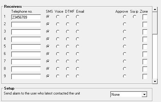
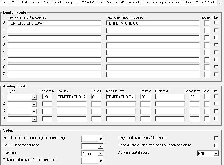
95 Screenshots Quick setup M1 Quick setup 2 M2 M3 d Quick setup 3 I1 I2 I3 95

96 Screenshots Quick setup 4 O3 M3-a V1 V3 V4 C3 C2 O1 96
7 USE THE COMMANDS INTERNET VOICE MESSAGES RECORD VOICE MESSAGE DURATION OF VOICE MESSAGES 64
 MANUAL FOR PROFORT GSM DEVICES 1 MANUAL FOR PROFORT GSM DEVICES 2 1.1 SPECIFICATIONS 2 1.2 FUNCTIONS 4 1.3 DESCRIPTION 6 1.4 SYSTEM ILLUSTRATION 7 2 MOUNTING 8 2.1 PREPARE THE UNIT 8 2.2 ELECTRIC MOUNTING
Manual for multiguard GSM/LAN units from Profort a/s Version 6.02
 Manual for multiguard GSM/LAN units from Profort a/s 1 MANUAL FOR PROFORT MULTIGUARD GSM/LAN UNITS 3 1.1 SPECIFICATIONS WALL-MOUNTED BOXES 3 1.2 FUNCTIONS WALL-MOUNTED BOXES 5 1.3 SPECIFICATIONS DIN/MOUNTING
Ontech GSM 9040/50. Reference Manual English -1 -
 Ontech GSM 9040/50 Reference Manual English -1 - Content Welcome... 5 This manual... 5 Text styles... 5 Support... 5 Disclaimer... 5 Overview... 6 Accessories... 6 External temperature sensor 9901... 7
SC-F3G User Manual 1.0
 SC-F3G User Manual 1.0 Table of Contents 1. Introduction... 3 2. Functions... 3 3. Features... 3 4. Package Contents... 3 5. Device Configuration... 4 6. Status LED signals... 5 7. Before You Start...
BURGLAR ALARM PANEL BS-468
 BURGLAR ALARM PANEL BS-468 Contents 1. Description... 3 2. Instructions for the user... 4 2.1Basic operations... 4 Complete system.... 4 Split system.... 4 2.2 Armed system indication... 5 2.3 Advanced
V1.0. Smart Home Alarm System. User Manual. APP download via QR Code scanning. Please read the manual carefully before using.
 V1.0 Smart Home Alarm System User Manual APP download via QR Code scanning Please read the manual carefully before using. Content FUNCTION PROFILE 2 THE SCHEMATIC GRAPH OF HOST 3 PROCESS OF BOOTING 6 OPERATION
Operation Manual Fighter ProVision Software. Version: 0.0 Revision: 1
 Operation Manual Fighter ProVision Software Version: 0.0 Revision: 1 TABLE OF CONTENTS 1. Introduction 5 2. Software Installation 5 3. PC Users 6 3.1 Introduction 6 3.2 Default Code 6 3.3 Edit PC User
CONTENT version Piccolo Object protection
 CONTENT version 1.14 1: PICCOLO - WIRELESS PROTECTION... 4 HOW THE PICCOLO SYSTEM WORKS... 4 SYSTEM DESCRIPTION... 4 DETECTORS... 4 ALARM RECEIVERS... 4 CENTRAL UNIT & PC... 4 FORWARDING ALARMS (INTERFACES)...
IP & SMS Alarm Communicator
 Models: WGSMSC You deserve to feel safe, secure & protected IP & SMS Alarm Communicator Quick Start Guide Thank you for purchasing a Watchguard IP & SMS Alarm Communicator This Quick Start Guide covers
System. For a better understanding of this product, please read this user manual thoroughly before using it.
 GSM Alarm System User s Manual For a better understanding of this product, please read this user manual thoroughly before using it. Chapter 1. Features Chapter 2. Control Panel Introduction Chapter 3.
GSM Alarm System. User s Manual. Profile. MOBILE CALL GSM Alarm System
 MOBILE CALL GSM Alarm System GSM Alarm System System disarmed 11/26/2013 User s Manual Profile For a better understanding of this product, please read this user manual thoroughly before using it. CONTENTS
With Magictrl, you can control MatiGard anytime & anywhere via your smartphone, even without data network.
 MatiGard User Guide 02 Menu Feature-------------------------------------------------------------- 05 Overviews---------------------------------------------------------- 07 Read Before Using-----------------------------------------------
GLOBAL. InstallatIon & operation manual
 InstallatIon & operation manual INDEX 1. INTRODUCTION... 5 2. FEATURES AND FUNCTIONS 2.1 Reporting Options... 2.2 Interfaces... 2.3 Programming... 2.4 Indicators and Controls...... 6 6 6 6 6 3. INSTALLATION...
ABOUT THIS DOCUMENT AND THE DOCUMENT STRUCTURE WE USE
 ABOUT THIS DOCUMENT AND THE DOCUMENT STRUCTURE WE USE isocket Smart Relay is a complex Smart House system which is installed in the fuse cabinet (electric cabinet) in the house. We therefore assume that
To activate using remote control: press [ ] key once. To activate using keyboard: on panel keyboard [ ] keys once.
![To activate using remote control: press [ ] key once. To activate using keyboard: on panel keyboard [ ] keys once.](/thumbs/93/113878877.jpg "To activate using remote control: press [ ] key once. To activate using keyboard: on panel keyboard [ ] keys once.") Table of Content 1.1General Description----------------------------------------------------------------------2 2.2System Setup-----------------------------------------------------------------------------3
Table of Content 1.1General Description----------------------------------------------------------------------2 2.2System Setup-----------------------------------------------------------------------------3
Remote switching machines with a SMS text from your mobile phone! Remote Monitoring your assets in the worldwide by your mobile Phone!
 Remote switching machines with a SMS text from your mobile phone! Remote Monitoring your assets in the worldwide by your mobile Phone! GSM SMS Controller DCS-130 User Manual Ver 1.20 Date Issued: 14-9-2010
USER S MANUAL. Profile. MOBILE CALL GSM Alarm System
 MOBILE CALL GSM Alarm System USER S MANUAL System disarmed 00/00/00 00:00 ARM STAY CALL 1 2 3 4 5 6 7 8 9 Power Set Signal Alarm SOS ESC 0 ENTER Profile For a better understanding of this product, please
Version 1.03 January-2002 USER S MANUAL
 Version 1.03 January-2002 1 USER S MANUAL 2 Version 1.03 January-2002 System Details CUSTOMER:...... PHONE:... FAX:... INSTALLED BY:...... PHONE:... FAX:... MAINTENANCE & SERVICE:...... PHONE:... FAX:...
HELPY QUICK-TL GSM INTL
 Alarm system for elevators HELPY QUICK-TL GSM INTL QUICK GUIDE 04/02/16 DESCRIPTION A B C D E F G H I L M N O Connector for external LEDs Connector for built-in loudspeaker Built-in loudspeaker Connector
GSM RFID VOICE Alarm System
 GSM RFID VOICE Alarm System User s Manual For a better understanding of this product, please read this user manual thoroughly before using it. CONTENTS [Function Instruction] [Control Panel] Control Panel
1. User features of the GSM dialer
 1. User features of the GSM dialer The JA60GSM dialer offers many useful features described in detail below. The installer should properly demonstrate the use of the system to the user after installation
GSM SMS Controller GSM SMS Alarm Unit S130 S140 S150. User Manual
 Remote switching machines with a SMS text from your mobile phone! Remote Monitoring your assets in the worldwide by your mobile Phone! GSM SMS Controller GSM SMS Alarm Unit S130 S140 S150 User Manual Ver
Elderly Care Alarm System
 Introduction 24/7 Peace of mind for your family The GSM Elderly Care Alarm System is a new released smart solution for take care of senior, aged, elder or disabled people on their daily life. Big LED display
Manual GPRS Data Logger PCE-GPRS 2
 PCE Americas Inc. 711 Commerce Way Suite 8 Jupiter FL-33458 USA From outside US: +1 Tel: (561) 320-9162 Fax: (561) 320-9176 info@pce-americas.com PCE Instruments UK Ltd. Units 12/13 Southpoint Business
D3D Wi-Fi GSM Smart Alarm System -User Manual
 D3D Wi-Fi GSM Smart Alarm System -User Manual D3D Wi-Fi / GSM Smart Alarm system (Model : D10). Please read all instructions carefully & follow steps for easy home installation. 1 P a g e D3D Wi-Fi / GSM
Sentient. Downloader Manual D4854
 Sentient Downloader Manual D4854 Dycon Ltd Tel: +44 (0)1443 471 060 Fax: +44 (0)1443 479 374 Cwm Cynon Business Park Mountain Ash CF45 4ER - UK www.dyconsecurity.com sales@dyconsecurity.com TABLE OF CONTENTS
ocbridge Plus SPECIFICATION 3. COMPONENTS Wireless sensors receiver, battery СR2032, manual, instalation CD.
 1 2 3 4 5 6 7 8 IN OFF ON + T S B J Т1 ocbridge Plus 1. FEATURES Wireless sensors receiver ocbridge is designated for connecting compatible Ajax devices to any third party wired central unit (panel) with
2G & 3G GSM Wireless Beam Alarm
 2G & 3G GSM Wireless Beam Alarm www.gsm-activate.co.uk MODEL RF - BEAM PAGE 1 Product Information Our 2G/3G GSM Wireless Beam Alarm is a standalone alarm system suitable for indoor and outside use. It
DYGIZONE GJD910 Lighting Controller & Enunciator
 DYGIZONE GJD910 Lighting Controller & Enunciator MASTER WIRING IDENTIFICATION Power up to the DygiZone and you will see: All the LED s (red,yellow,green and blue buttons) will flash All the LCD icons will
Mobeye CM2410 GSM fire alarm communicator
 PORTAL USER MANUAL Mobeye CM2410 GSM fire alarm communicator Accessory for Ei Electronics fire detector SW version 5.n Incl. CM2400 Attention! Very important This user manual contains important guidelines
2G & 3G GSM Door Contact Alarm
 2G & 3G GSM Door Contact Alarm www.gsm-activate.co.uk MODEL RF - PIR PAGE 1 Product Information Our 2G/3G GSM Door Contact Alarm is a standalone alarm system for smaller rooms inside properties. It will
2G & 3G GSM Portable PIR Alarm
 2G & 3G GSM Portable PIR Alarm www.gsm-activate.co.uk MODEL RF - PORTABLE-PIR PAGE 1 Product Information Our 2G/3G Portable PIR Alarm is a standalone alarm system suitable for indoors or outside usage.
TURN OFF ALARM AUTO ALARM RESET WRITE A COMMENT DISPLAY THE GUARDS GUARD FUNCTION RELAY INTERFACE:...
 CONTENT version 2.03 1: PICCOLO - WIRELESS PROTECTION... 3 HOW THE PICCOLO SYSTEM WORKS... 3 SYSTEM DESCRIPTION... 3 DETECTORS... 3 ALARM RECEIVERS... 3 PICCOLO SERVER UNIT... 3 FORWARDING ALARMS (INTERFACES)...
IRIS Touch Firmware Enhancements and Additions from Version to Version
 Overview IRIS Touch Firmware Enhancements and Additions from Version 1.14.3 to Version 1.19.1 This document details enhancements to the feature set of the IRIS Touch from firmware Version 1.14.3 to Version
MOBILE CALL GSM Alarm System User s Manual
 MOBILE CALL GSM Alarm System User s Manual Profile For a better understanding of this product, please read this user manual thoroughly before using it. Contents Function Introduction (3) Alarm Host Diagram
CG500SKE SKYEYE GATEWAY USER MANUAL VERSION OCTOBER Disclaimers and Copyright
 CG500SKE SKYEYE GATEWAY USER MANUAL CG500SKE SkyEYE Gateway VERSION 1.2 26 OCTOBER 2014 Disclaimers and Copyright Nothing contained in this publication is to be construed as granting any right, by implication
User s Guide. SUB-MA7240O-0001.OG.Solution doc. Created: 6/05/03. Last Updated: 23/09/03. MA7240AO-0001 Version 1.0
 User s Guide SUB-MA7240O-0001.OG.Solution40-111.doc Created: 6/05/03 Last Updated: 23/09/03 MA7240AO-0001 Version 1.0 2 Table Of Contents User List...6 Quick Reference..7 Features...7 Keypad User's Guide...8
1. Introduction. 2. Product overview
 1. Introduction The AG400011 GSM Alarm panel is a control panel that is compatible with other H-net security devices from Everspring, such as wireless sensors, remote keyfobs, tags, and keypad. With this
TYDOM 315. * _Rev.2* GSM domotics transmitter. 1. Presentation
 TYDOM 5 GSM domotics transmitter ) Présentation. Presentation Delta Dore hereby declares that the equipment complies with the essential requirements and other relevant provisions of the R&TTE Directive
SK642 THE TELEPHONE DIALER REQUIRES A LAND TELEPHONE LINE TO MAKE OUTGOING CALLS AND ELECTRICITY.
 SK642 WIRELESS WATER ALARM SYSTEM WITH AUTO DIALER OWNER'S MANUAL AND SET UP INSTRUCTIONS. Thank you for choosing Ideal Security s Wireless Water Alarm with Telephone Dialer. Please read through complete
Preface. Thank you for purchasing our GSM Security Alarm System ( The System )! The System will keep your home and property safe around the clock.
! The System will keep your home and property safe around the clock.") Preface Thank you for purchasing our GSM Security Alarm System ( The System )! The System will keep your home and property safe around the clock. The GSM Security Alarm ( The Alarm ) adopts the most advanced
Preface Thank you for purchasing our GSM Security Alarm System ( The System )! The System will keep your home and property safe around the clock. The GSM Security Alarm ( The Alarm ) adopts the most advanced
M3092 Programmer. User s Manual. M3096B-33 E Copyright 2017 SELCO
 User s Manual Copyright 2017 SELCO SELCO Betonvej 11 - DK-4000 Roskilde Denmark Phone: 45 7026 1122 - Fax: 45 7026 2522 e-mail: selco@selco.com www.selco.com Table of contents 1 INTRODUCTION...4 2 SOFTWARE
 3i SECURITY with i-mode Welcome to the future of security. Today with your i-mode telephone you have full control of your home and automobile even when you are not present. You may see directly on your
PORTAL USER MANUAL. Mobeye WaterGuard-FS. Float sensor CM2300FS. SW version 5.n
 SW version 5.n PORTAL USER MANUAL Mobeye WaterGuard-FS Float sensor CM2300FS Attention! Very important This user manual contains important guidelines for the installation and usage of the Mobeye device
HELPY CONTROLLER QUICK GUIDE
 Alarm system for elevators compliant with the European Standard EN 81-28:2018 HELPY CONTROLLER QUICK GUIDE 05/04/2019 DESCRIPTION Autodialer specifically designed for installation on elevator controller.
USER S MANUAL HOME ENERGY SAVINGS REMOTE CAMERA INTERNET USER INTERFACE TEMPERATURE ALARMS BURGLARY PROTECTION DOOR SECURITY FIRE SAFETY
 + USER S MANUAL 1.0 HOME ENERGY SAVINGS REMOTE CAMERA INTERNET USER INTERFACE TEMPERATURE ALARMS BURGLARY PROTECTION DOOR SECURITY FIRE SAFETY SECURITY KEYPAD WITH PROXIMITY TAGS PREVENTION OF WATER DAMAGES
Thank you for choosing Ideal Security s Home Security System with Telephone Dialer.
 SK618 WIRELESS ALARM SYSTEM WITH AUTO DIALER OWNER'S MANUAL Thank you for choosing Ideal Security s Home Security System with Telephone Dialer. If at any time during your installation you have any questions
Security System. User Guide for the LED Command Center
 Security System User Guide for the LED Command Center National Security Systems Inc (800)457-1999 MY SECURITY COMPANY IS: CALL BEFORE TEST: THIS SECURITY SYSTEM IS CONNECTED TO TELEPHONE NUMBER: THE SECURITY
GSM Emergency Alarm. User s Manual. For a better understanding of this porduct,please read this user manual thoroughly before using it.
 Version: MS1 GSM Emergency Alarm User s Manual For a better understanding of this porduct,please read this user manual thoroughly before using it. CONTENTS CONTENTS Ⅰ. Introduction Ⅱ. Product Appearance
Advisor Advanced Mobile Application User Manual
 Advisor Advanced Mobile Application User Manual Content Warnings and Disclaimers 2 Advanced Mobile 2 Contact information 2 Description 2 Screen navigation 4 Gestures 4 Menu 4 Help navigation 4 Login 5
DEFA HOME. User Manual Base Unit PRO
 DEFA HOME User Manual Base Unit PRO Table of Contents Overview 5 Logging into the app 9 Home 10 Calendar 13 Adding an event 14 Editing an event 15 Zones 16 Switch mode 17 Thermostat mode 19 Regulator
User Manual. Dryer Controller M720
 User Manual Dryer Controller M720 Hardware version 1.00 Software version 1.00 Preliminary version Manual M720 Dryer controller Page 1 of 42 Document history Preliminary version: - Created in April, 2009
All-In-One Wireless Security System V1.0. Model #: MG Reference and Installation Manual
 All-In-One Wireless Security System V1.0 Model #: MG-6060 Reference and Installation Manual Table of Contents Introduction... 3 About Magellan and this Manual... 3 Conventions... 3 Specifications... 3
SCAN200E USER S MANUAL
 SCAN200E USER S MANUAL Code No. 2071 1052 rev. 1.4 Code No. 2071 1052 Rev. 1.4 Page 2/16 SCAN200E User s Manual Foreword This manual is for SCAN200E Controller running software version 2.03 or later. We
All-In-One Wireless Security System V1.0. Model #: MG-6060
 All-In-One Wireless Security System V1.0 Model #: MG-6060 Reference and Installation Manual DRAFT Table of Contents Introduction... 5 About Magellan and this Manual... 5 Conventions... 5 Specifications...
All-In-One Wireless Security System V3.2 Programming Guide. Model # MG6130 / MG6160
 All-In-One Wireless Security System V3.2 Programming Guide Model # MG6130 / MG6160 We hope this product performs to your complete satisfaction. Should you have any questions or comments, please visit www.paradox.com
Ion Gateway Cellular Gateway and Wireless Sensors
 Page 1 of 9 Account & Network Setup If this is your first time using the Ion Gateway online system site you will need to create a new account. If you have already created an account you can skip to the
Any additional devices linked to the system ET08 (computer, sensors, relays etc.) must be approved by LST EN standard.
 must be approved by LST EN standard.") COMMUNICATOR ET08 User Manual v1.0 Safety instructions Please read and follow these safety guidelines in order to maintain safety of operators and people around: GSM communicator (gateway) ET08 (further
COMMUNICATOR ET08 User Manual v1.0 Safety instructions Please read and follow these safety guidelines in order to maintain safety of operators and people around: GSM communicator (gateway) ET08 (further
GSM PROTECT ANTI-THEFT ALARM WITH GPS TRACKING & MOBILE PHONE ALERTS
 GSM PROTECT ANTI-THEFT ALARM WITH GPS TRACKING & MOBILE PHONE ALERTS Remote monitoring & Control using your mobile phone. www.gsm-activate.co.uk MODEL NUMBER VAN001 PAGE 1 Product Information The GSM Protect
SA 2650 Kit User Manual
 SA 2650 Kit User Manual Table of Contents 1. System Installation Planning 1 2. Device Introduction 3 3. Getting Started 6 4. System Default Setting 10 5. Connect2Home Application 11 6. System Information
USER MANUAL S203. Controller for three circuits. - control for 2 heating circuits - 1 domestic hot water control. Saving energy, creating comfort
 USER MANUAL S203 Controller for three circuits - control for 2 heating circuits - 1 domestic hot water control Saving energy, creating comfort This user manual consists of two parts. Issues that are intended
Thank you for choosing Ideal Security s Home Security System with Telephone Dialer.
 SK618 WIRELESS ALARM SYSTEM WITH AUTO DIALER OWNER'S MANUAL Thank you for choosing Ideal Security s Home Security System with Telephone Dialer. If at any time during your installation you have any questions
AUTODIALER SYSTEM FOR LIFTS MANUAL HELPY 2W-V
 AUTODIALER SYSTEM FOR LIFTS MANUAL HELPY 2W-V 05/06/2018 DESCRIPTION Autodialer to be fitted behind the cop or on top of the car / retrofit. A Connector for Esse-ti power supply (12 Vdc) B Micro SD Card
with internal sensor (channel 1) with an external sensor (channel 2) A-Editor software, Professional AK20 version (not for version AK4)
 with an external sensor (channel 2) A-Editor software, Professional AK20 version (not for version AK4)") Examples of use Example Creating an SMS-based alarm with confirmation A project file must first be created using the A-Editor software. This project file is then stored in the alarm modem. The alarm modem
Examples of use Example Creating an SMS-based alarm with confirmation A project file must first be created using the A-Editor software. This project file is then stored in the alarm modem. The alarm modem
ATSTORM v2. The sensor with FCES technology is connected to the interface with a communication cable.
 ATSTORM v2 ATSTORM v2 is a storm detector that measures the environmental electric field. It is fully automatic, without mobile parts, robust and highly reliable The storm detector ATSTORM v2 basic configuration
EZY SWITCH. SMS-IRR-4 System Monitor Installation Manual
 EZY SWITCH SMS-IRR-4 System Monitor Installation Manual Table of Contents COMMANDS Getting Started Setting Up Initial User 7 Adding a User 8 Removing a User 8 Adding an Administrator 8 Removing the Administrator
Ref.1067/032 Ref.1067/042
 DS1067-033A Mod. 1067 LBT8631 BUS CONTROL PANEL 8/32 INPUTS Ref.1067/032 Ref.1067/042 USER MANUAL TABLE OF CONTENTS 1 PREFACE... 5 2 COMMAND DEVICES... 6 2.1 1067/021 DISPLAY KEYPAD... 6 2.2 ELECTRONIC
Monitoring Solutions
 GSM Systems Monitor: Temperature, Humidity, Power, Water, Smoke, Carbon Monoxide and More September 2016 Table of Contents GSM Systems... 3 Argon 100 GSM... 3 Ares 12 & 14 GSM... 4 Poseidon2 4002... 5
WIRELESS ALARM SYSTEM WITH TELEPHONE AUTO DIALER
 BAT.LOW AC WIRELESS ALARM SYSTEM WITH TELEPHONE AUTO DIALER THE SYSTEM THAT CALLS YOU! Our WIRELESS ALARM SYSTEM WITH TELEPHONE AUTO DIALER is designed to allow you to create your own security system.
 GSM AUTO DIALLER WIRELESS ALARM SYSTEM MODEL AD-SD MODEL AD-SD-W www.gsm-activate.co.uk Model AD-SD & Model AD-SD-W PAGE 1 Product Information Our AD-SD Auto Dialler is a versatile unit which can be attached
Careline Anna Careline GSM
 Careline Anna / Careline GSM Programming and installation manual List of contents 1 Introduction... 3 1.1 General description of Careline Anna/GSM... 3 1.2 General description of Tx4 alarm transmitter...
COMMUNICATOR ET08 / ET081
 COMMUNICATOR ET08 / ET081 User Manual v1.2 Safety instructions Please read and follow these safety guidelines in order to maintain safety of operators and people around: GSM communicator ET08 / ET081 (further
It is necessary to match all peripherals with the EVOLVEO Alarmex main unit before the first use. For safety reasons, they are not factory paired.
 Thank you for purchasing the GSM alarm system EVOLVEO Alarmex. Please, read this user manual carefully and follow strictly the set instructions. This product uses the most modern technology, yet you cannot
GSM Smart Home Alarm Apparatus. [99+4 defense zones] Instruction for Use
![GSM Smart Home Alarm Apparatus. [99+4 defense zones] Instruction for Use](/thumbs/83/87979951.jpg "GSM Smart Home Alarm Apparatus. [99+4 defense zones] Instruction for Use") GSM Smart Home Alarm Apparatus [99+4 defense zones] Instruction for Use Table of content Ⅰ. Introduction to the system... 2 Ⅱ. Introduction to function... 2 Ⅲ. System composition and use method... 3 Ⅳ.
GSM Smart Home Alarm Apparatus [99+4 defense zones] Instruction for Use Table of content Ⅰ. Introduction to the system... 2 Ⅱ. Introduction to function... 2 Ⅲ. System composition and use method... 3 Ⅳ.
Instructions manual. By-alarm. By-alarm Manager software
 Instructions manual By-alarm By-alarm Manager software Index 1. Procedure for the complete programming of the By-alarm system 5 Operations to be carried out prior to the programming with By-Alarm Manager
PERMACONN PM1030 Includes DI300. Installation Manual
 PERMACONN PM1030 Includes DI300 Installation Manual Radio Data Comms Unit 5/20-30 Stubbs Street Silverwater NSW 2128 Telephone: 02 9352 1777 Facsimile: 02 9352 1700 Introduction The PERMACONN system provides
Profile. For a better understanding of this product, please read this user manual thoroughly before using it.
 Intelligent GSM Auto-Dial Alarm System User s Manual Profile For a better understanding of this product, please read this user manual thoroughly before using it. Contents Function Introduction (3) Alarm
ION Meter Alerts TECHNICAL NOTE NOVEMBER In This Document
 70072-0125-01 TECHNICAL NOTE NOVEMBER 2006 ION Meter Alerts A PowerLogic ION meter can send alerts to indicate a user specified power system condition such as a power quality problem (including surges,
Operations Manual TS400. Test Station for G450/G460 Gas Detector
 TS400 Test Station for G450/G460 Gas Detector Operations Manual 1194 Oak Valley Dr, Ste 20, Ann Arbor MI 48108 USA (800) 959-0329 (734) 769-0573 www.goodforgas.com GfG Products for Increased Safety Congratulations
Contents. Glossary
 Contents Glossary ------------------------------------------------------------------------------------------------------ 6 1. Introduction to the IDS 1632 -------------------------------------------------------------
EasyTronic III MANUAL SERVICE
 rev.6 EasyTronic III MANUAL SERVICE General characteristics: Power supply 24 Vac ±15% Max consumption at 24Vac 300mA Relay outputs 6 Maximum relay current 8 A res. Serial standard RS232 2 Serial standard
Wolf Guard Touch Keypad GSM Wireless alarm system User s Manual
 Wolf Guard Touch Keypad GSM Wireless alarm system User s Manual Page 1 Warning Do not remove the front or back cover of the unit and keep it intact. There are no parts inside this unit that can be repaired
PowerLogic ION Setup Meter Configuration Software Configuration Guide
 PowerLogic ION Setup Meter Configuration Software Configuration Guide 70002-0293-03 12/2010 Conventions Used in this Manual This section describes the symbols and terminology used in this guide. Symbols
Security designed for your lifestyle
 Security designed for your lifestyle The Paradox Insight : The Big Picture A single CAT5 or higher cable can be used to wire a single HD77 camera. Camera Detector Module HD 720p camera Quad PIR with auto
Ethernet General Purpose
 Ethernet General Purpose Technical Manual Revision 1.03 8 November 2013 Pakton Technologies IO PAE224 Ethernet GPIO Manual.docx Page 1 of 22 Revision 1.03 Last updated 8/11/2013 Table of Contents INTRODUCTION...3
Security System. User s Guide for the Text Command Center
 User s Guide for the Text Command Center MY ALARM COMPANY IS: CALL BEFORE TEST: THIS SECURITY SYSTEM IS CONNECTED TO TELEPHONE NUMBER: THE SECURITY CONTROL PANEL IS CONNECTED TO THE PHONE JACK LOCATED:
Revision November 2013 JVA Technologies. Ethernet General Purpose IO Technical Manual
 Revision 1.03 8 November 2013 JVA Technologies Ethernet General Purpose IO Technical Manual www.jva-fence.com.au Table of Contents INTRODUCTION...3 Scope and Purpose...3 Glossary...3 SPECIFICATIONS...4
3G GSM AUTO DIALER. Remote monitoring & Control using your mobile phone. MODEL NUMBER 3GAD1
 3G GSM AUTO DIALER Remote monitoring & Control using your mobile phone www.gsm-activate.co.uk MODEL NUMBER 3GAD1 PAGE 1 Product Information Our 3G GSM Auto Dialer is a versatile unit which can be attached
Dryer Controller M720
 User Manual Dryer Controller M720 Hardware version 2.00 Software version 2.00 Manual M720 Dryer controller Page 1 of 60 Document history Preliminary version: - Created in April, 2009 Hardware Version 2.00,
Section 9 System Operation
 Section 9 System Operation Operation of the control panel is simple. Menus guide you step-by-step through operations. This section of the manual is an overview of the operation menus. Please read this
Summit 3208GLD USER MANUAL. Electronics Line
 Summit 3208GLD USER MANUAL Electronics Line Table of Contents 1: Introduction... 2 2: Overview... 3 3: Keypad Functions... 4 3.1: Keypads... 4 3.2: 3108 LCD Keypad Layout... 4 4: Basic System Operation...
HOME MANAGEMENT GATEWAY
 LS-20 The Universal Box HOME MANAGEMENT GATEWAY OPERATION MANUAL V1.00 INTRODUCTION Thank you for purchasing the LS-20 the Universal Home Management Gateway. By adopting modern embedded system and Cloud
Security GSM Alarm System
 Security GSM Alarm System USER MANUAL 4 wired and 6 wireless defense zones; Can preset and store 6 voice phones and 3 message phones; Remote two-way intercom; Telephone (mobile phone) remote control programming;
IndigoVision Alarm Panel. User Guide
 IndigoVision Alarm Panel User Guide THIS MANUAL WAS CREATED ON 2/21/2017. DOCUMENT ID: IU-AP-MAN002-4 Legal considerations LAWS THAT CAN VARY FROM COUNTRY TO COUNTRY MAY PROHIBIT CAMERA SURVEILLANCE. PLEASE
Telemetry Communications Device. Installation Guide. Interface for the Emizon managed network. Issue 1: February 2008
 TCD Telemetry Communications Device Installation Guide Interface for the Emizon managed network Issue 1: February 2008 This guide sets out a simple check list together with a step-by-step guide to the
HRX Technical Manual. Version 1.2
 HRX 5000 Technical Manual Version 1.2 Contents: Specification...2 Connectors...5 RS-485 Network Connectors (J6 and J7)...5 RS-232 to Printer (J19)...6 RS-232 to PC (J8)...7 TCP/IP...8 Power (J21)...9 Fire
IRIS Touch 400 & 600 Range Installation Manual. Honeywell Galaxy Range. Version 2.0
 IRIS Touch 400 & 600 Range Installation Manual Honeywell Galaxy Range Version 2.0 Table of Contents 1 System Overview... 4 2 IRIS Touch 440 & 640 PCB Layout... 5 3 Connection & Configuration for Honeywell
Laptop / PC Programming Manual
 Laptop / PC Programming Manual Doc. # Fire PC Program rev B 01.07 This Document is property of Evax Systems, Inc. The Evax Fire Solutions Programmer Components 2 1.0 System Setup 4 1.1 Interface Setup
Added password for IP setup page : Password must be in IP format!
 NETWORK POWER MONITOR Release : 21 August 2014 Hardware Version : Version 7 Firmware version 1.00 PC Application Software : Version (latest)...2 Added password for IP setup page : Password must be in IP
User manual. Epi-Care mobile. Danish Care Technology ApS Energivej 3, DK-4180 Sorø version 1.15 Phone: Page 1 of 17
 User manual Epi-Care mobile Phone: +45 58 50 05 65 Page 1 of 17 Introduction The purpose of the Epi-Care mobile epilepsy alarm is to ensure severe seizures are not overseen. Epi-Care mobile recognizes