Air Vents AV-406. Proven Same proven, free-floating all stainless steel mechanism as used in Armstrong steam traps.
|
|
|
- Carmel Dorsey
- 5 years ago
- Views:
Transcription
1 Air Vents

2 Air Vents Proven Same proven, free-foating a stainess stee mechanism as used in Armstrong steam traps. Leak-tight Positive cosing, free-foating stainess stee ever ensures eak-tight cosing under a conditions. Air Vents Body options Variety of body materias avaiabe: poysufone, cast iron, forged stee and a stainess stee. A materia for every appication. High pressure Armstrong air/gas vents can hande appications to 186 bar. AV-406
3 Seecting The Armstrong Air/Gas Vent With the desired capacity in m³/h known, find the orifice size required from the tabe on this page. Then find the vent or vents with the correct orifice size on pages AV-410 to AV-419 that wi operate at the required pressure with a iquid of the specific gravity being handed. Exampe Find a mode number that wi vent 88,3 m³/h of air (incuding safety factor of 1,5-2,0) from a iquid with a specific gravity of 0,93 at 17 bar. Using the tabe beow, foow the 17 bar ine across to the number 103. Orifice size is 5/32". Now go to pages AV-410 to AV-419 checking the 5/32" orifice ines to ocate a vent for 17 bar or higher with 0,90 gravity iquid. For Venting During Fiing Ony If a vent is required ony for getting rid of air when a system is started up, such as when starting up a deep we pump or fiing an empty pipe, tank or other vesse, abiity of the vent to open at operating pressure can be ignored. In these cases, a mode number with a arge orifice for fast venting may be seected, but the vent wi not open after air is expeed and the system reaches operating pressure. Note: Since specific gravity fas between 0,95 and 0,90, use 0,90 gravity data. The mode 3-AV on page AV-412 is the one to use. Tabe AV Discharge of Air Through an Orifice in m³/h at a Standard Atmospheric Pressure of 1 bar(a) and 21 C Pressure Orifice Diameter, inch barg 1/16" 5/64" 3/32" #38 7/64" 1/8" 9/64" 5/32" 3/16" 7/32" 1/4" 9/32" 5/16" 11/32" 3/8" 7/16" 1/2" 9/16" 5/8" 3/4" 7/8" 1 1/16" 0,3 1,10 1,72 2,46 2,63 3,36 4,38 5,56 6,85 9,87 13,4 17,5 22,3 27,4 33,1 39,4 53,7 70,2 88, ,4 1,21 1,87 2,70 2,89 3,67 4,79 6,07 7,49 10,8 14,7 19,2 24,3 29,9 36,2 43,2 58,6 76,6 97, ,5 1,29 2,02 2,91 3,11 3,96 5,16 6,54 8,07 11,6 15,8 20,7 26,2 32,3 39,1 46,4 63,2 82, ,6 1,46 2,28 3,28 3,52 4,47 5,83 7,37 9,11 13,1 17,8 23,3 29,6 36,4 44,0 52,5 71,4 93, ,8 1,67 2,62 3,75 4,03 5,11 6,68 8,46 10,4 15,0 20,4 26,7 33,8 41,8 50,5 60,1 81, ,0 1,85 2,91 4,18 4,47 5,67 7,42 9,40 11,6 16,7 22,8 29,7 37,5 46,4 56,1 66,8 90, ,4 2,12 3,31 4,77 5,11 6,49 8,48 10,7 13,3 19,0 26,0 34,0 43,0 53,0 64,1 76, ,7 2,34 3,67 5,28 5,66 7,19 9,40 11,9 14,7 21,1 28,7 37,5 47,6 58,6 71,0 84, ,0 2,62 4,08 5,88 6,29 8,00 10,4 13,2 16,3 23,4 31,9 41,8 52,8 65,2 79,0 94, ,4 2,94 4,60 6,63 7,08 9,02 11,8 14,9 18,3 26,5 36,0 47,1 59,6 73,6 89, ,8 3,28 5,11 7,37 7,88 10,0 13,1 16,6 20,4 29,4 40,1 52,3 66,3 81,9 99, ,1 3,60 5,62 8,10 8,66 11,0 14,4 18,2 22,4 32,5 44,2 57,6 72,9 90, ,5 3,92 6,13 8,83 9,45 12,0 15,7 19,9 24,5 35,3 48,1 62,9 79,5 98, ,1 4,57 7,14 10,3 11,0 14,0 18,3 23,1 28,5 41,1 55,9 73,1 92, ,8 5,20 8,14 11,7 12,5 16,0 20,9 26,3 32,6 46,9 63,7 83, ,5 5,84 9,12 13,2 14,1 17,8 23,4 29,6 36,5 52,7 71,5 93, ,2 6,47 10,1 14,6 15,6 19,9 26,0 32,8 40,4 58,3 79, ,0 7,12 11,1 16,0 17,2 21,7 28,4 36,0 44,5 64,1 87, ,6 7,75 12,1 17,5 18,7 23,8 30,9 39,2 48,4 69,7 94, ,5 8,68 13,6 19,5 20,9 26,7 34,8 44,0 54,4 78, ,3 16,0 23,1 24,8 31,4 41,1 52,0 64,2 92, ,4 20,9 30,2 32,3 41,1 53,7 68,0 83, ,5 25,8 37,2 39,9 50,6 66,3 83, ,7 30,8 44,3 47,4 60,3 78,7 99, ,0 40,6 58,4 62,5 79, ,3 50,3 72,5 77,6 98, ,4 60,1 86,6 92, ,9 74, ,5 99, Air Vents AV-407
4 Air Vent ID Charts Tabe AV Armstrong Air Vents Iustration Type Series 1-AVCW See-thru Free Foating Lever Air Vents for Ozone Appications Fow Direction Connection Type Max. Aow. TMA Body Materia Mode Press. C barg Screwed PBT Cap (Poybutyene Terephthaate) Poysufone Body Max. Oper. Press. barg 1-AVCW 10 Connection Size 1/8" 1/4" 1/2" 3/4" 1" 1 1/2" 2" s ««Located on Page AV-424 Series 1-AVC See-Thru Free Foating Lever Air/Gas Vents Screwed Nyon Cap Poysufone Body 1-AVC 10 ««AV-410 Series 21-AR Fixed Pivot Ba Foat Air/Gas Vents Screwed ASTM A48 Cass 30 Cast Iron 21-AR 17 AV-411 Series Fixed Pivot Ba Foat Air/Gas Vents Screwed Socketwed Fanged 41 or or 399 ASTM A105 Forged Stee AR VAR 4,5 41 AV-411 Series 1, 2, 3, 6 Free Foating Lever Air/Gas Vents Screwed Fanged ASTM A48 Cass 30 Cast Iron 1-AV 21 2-AV 3-AV 6-AV 17 ««AV-412 Series 30 Free Foating Lever Air/Gas Vents Screwed Socketwed Fanged 41 or or or or 399 ASTM A105 Forged Stee 32-AV AV 62 AV-414 Air Vents Series 10 Free Foating Lever Air/Gas Vents Screwed Socketwed (22 and 13 ony) Fanged 69 or or or or or or or or L Stainess Stee 36-AV AV 28 ««22-AV AV 39 AV-418 Series HLAR High Leverage Air/Gas Vents Screwed Socketwed Fanged 69 or or 399 ASTM A105 Forged Stee 2313 HLAR 2315 HLAR 69 11/4" 11/2" 2316 HLAR AV-416 Series HLAR High Leverage Air/Gas Vents Screwed Socketwed Fanged 103 or or or 454 ASTM A or 482 Gr. F22 Forged Stee 2413 HLAR HLAR 2416 HLAR /4" 11/2" AV-416 «1/4" outet connection ««1/2" outet connection Side connection avaiabe s Aternate inet 1/2" Side connection not avaiabe Fange seection may imit pressure and temperature rating. AV-408
5 Air Vent ID Charts Tabe AV Armstrong Air Vents Iustration Type Series HLAR High Leverage Air/Gas Vents Series TTF Thermostatic Air Vents Fow Direction Connection Type Screwed Socketwed Fanged Straight-Thru Right Ange Max. Aow. Press. barg 146 or or or 207 TMA C 38 or or or Body Materia ASTM A182 Gr. F22 Forged Stee 304-L Stainess Stee Mode 25133G- HLAR 25155G- HLAR 26155G- HLAR TTF-1 TTF-1R Max. Oper. Press. barg Connection Size 1/8" 1/4" 1/2" 3/4" 1" 1 1/2" 2" /4" /4" 186 Located on Page AV AV-420 TAVB Thermostatic Beows with Integra Vacuum Breaker Series TV-2 Thermostatic Air Vents Straight-Thru Screwed Screwed L Stainess Stee ASTM B62 Cast Bronze TAVB-2 10 AV-421 TAVB-3 TV-2 8,5 AV-423 Series TS-2 Thermostatic Air Vents Threaded 3,5 149 ASTM B62 Bronze TS-2 3,5 AV-422 AV-11, AV-13 Hydronic System Air Vents Screwed 3, Brass AV-11 AV-13 3,5 10 AV-425 Air Vents «1/4" outet connection ««1/2" outet connection Side connection avaiabe s Aternate inet 1/2" Side connection not avaiabe Fange seection may imit pressure and temperature rating. A modes compy with the Pressure Equipment Directive PED 97/23/EC. For detais, see specific product page or Armstrong PED Certificate. AV-409
6 1-AVC See-Thru Air Vent For Pressures to 10 bar or Specific Gravity Down to 0,80 Aternate Inet Outet 1-AVC Inet Air Vents A See-Thru Body So You Know When It s Working Now, you can iteray see what you ve been missing the eary warning signs of a system probem. Since you know the operating condition of the air vent, you won t have to waste time and money scheduing maintenance that isn t needed. In other words, you wi be abe to react to a condition before it becomes a probem. A simpe ba foat mechanism requiring no eectricity to operate, the new Armstrong 1-AVC discharges automaticay ony when air/gas are present. That means no iquid oss as with manua venting. An Inside Look See-thru body means you can observe changing conditions as they occur. See a probem in the making instead of having to dea with it after the fact. Tabe AV AVC List of Materias Name of Part Materia Cap Reinforced Nyon Body Poysufone* O-Rings (Body Cap and Fitting) Nitrie Eastome Compound Foat Lever and Screws Stainess Stee Vave & Seat Stainess Stee Fitting & Pipe Pug Reinforced Nyon Retainer Ring Zinc Pated Stee * UV sensitive. Efficient Operation Simpe ba foat mechanism discharges ony when air is present so it doesn t waste iquid. Positive Seating Free-foating vave mechanism assures positive seating so it prevents iquid oss. There are no fixed pivots to wear or create friction, and wear points are heaviy reinforced for ong ife. Reduced Maintenance Stainess stee internas mean corrosion resistance and reduced maintenance. Corrosion Resistance Long-asting poysufone body and reinforced nyon cap resist corrosion and provide ong, troube-free service ife. Compare and Save the Difference Seeing is reay beieving especiay when you compare the Armstrong see-thru air vent with manua venting. Measure the differences in the time and money you can save with a more efficient, easier-to-maintain system. For more information or technica assistance, contact your oca Armstrong Representative. Note: The Armstrong 1-AVC shoud not be used in an environment where there are high eves of ketones or chorinated or aromatic hydrocarbons. Tabe AV AVC Physica Data mm Inet Connection Outet Connection 15 A Face-to-Face 89 B Height 171 C Bottom to CL 152 Maximum Aowabe Pressure (Vesse Design) C Maximum Operating Pressure 10 bar Specific Gravity Range 1,00 to 0,80 Weight in kg (screwed) 0,45 A sizes compy with the artice 3.3 of the PED (97/23/EC). Tabe AV AVC Capacity Differentia Pressure bar Orifice size (in) m³/h 1,0 7,3 2,0 11,0 3,5 16,1 5,0 1/8" 22,2 7,0 28,7 8,5 34,8 10,0 41,1 Note: Discharge of air through an orifice in m³/h at a standard atmospheric pressure of 1 bar(a) and 21 C. A dimensions and weights are approximate. Use certified print for exact dimensions. Design and materias are subject to change without notice. AV-410
 N/A 300 305 D 141 K 33 32 L 84 LL (PN100*) N/A 124 129 Weight in kg (screwed & SW) 4 14")
7 Fixed Pivot Ba Foat Air/Gas Vents For Pressures to 41 bar or Specific Gravity Down to 0,83 Mode 21-AR Mode AR/VAR Tabe AV AR Physica Data Mode No. Cast Iron Forged Stee 21-AR AR/VAR Pipe Connections mm mm A B BB (PN100*) N/A D 141 K L 84 LL (PN100*) N/A Weight in kg (screwed & SW) 4 14 Weight in kg (fanged PN100*) N/A 15,8 17,8 Maximum Aowabe Pressure (Vesse Design) C** C C * Other fange sizes, ratings and face-to-face dimensions are avaiabe on request. ** Viton vave seat insert imited to 204 C. A modes compy with the artice 3.3 of the PED (97/23/EC). May be derated depending on fange rating and type. Tabe AV AR Maximum Operating Pressures Minimum Specific Gravity 0,49 0,84 Foat weight in grams Orifice (in) Maximum Operating Pressure in bar 7/32" 1,2 3/16" 1,6 5/32" 2,3 9/64" 2,8 1/8" 3,6 3/32" 6,4 5/64" 9,2 1/16" 14,0 1/16" 17,0 21-AR A sma, high-quaity economica air vent. It empoys a singe ever with a fixed pivot and viton seat, ensuring a tight shut-off AR/VAR Forged stee version of the Mode 21 with a arger foat and higher everage. Avaiabe with screwed, socketwed or fanged connections. Tabe AV AR/VAR Maximum Operating Pressures Minimum Specific Gravity 0,83 Foat weight in grams 143 Mode Maximum Operating Pressure Orifice (in) in bar AR VAR 1/4" 1,5 7/32" 1,9 3/16" 2,7 5/32" 3,8 9/64" 4,7 1/8" 12,0 3/32" 21,0 5/64" 31,0 1/16" 41,0 Air Vents Tabe AV List of Materias Mode No. Vave Seat Leverage System Foat Body & Cap Gasket Boting 21-AR AR VAR Stainess Stee Stainess Stee with *Viton Insert Stainess Stee Stainess Stee ASTM A48 Cass 30 Cast Iron ASTM A105 Forged Stee Non-Asbestos Note: Above vents avaiabe in T-316 SS bodies and caps and a SS internas. Auminum body and cap avaiabe for Mode 21-AR ony. * Other seat insert materias avaiabe. Consut factory. Bots SAE J429 Gr 2 Nuts ASTM A563 Gr A Bots ASTM-A193 Gr. B7 Nuts ASTM-A194 Gr. 2H A dimensions and weights are approximate. Use certified print for exact dimensions. Design and materias are subject to change without notice. AV-411

8 Free Foating Lever Air/Gas Vents Cast Iron For Pressures to 21 bar or Specific Gravity Down to 0,40 Mode 1-AV Mode 2-AV, 3-AV and 6-AV Armstrong free foating ever Air/Gas Vents use the same bodies, caps, ever mechanisms, vaves and seats of Armstrong inverted bucket steam traps that have been proven in years of service. Eiptica foats and high everage make it possibe to open arge orifices to provide adequate capacity for vent size and weight. The hemispherica vave, seat and everage are identica in design, materias and workmanship to those for saturated steam service up to 69 bar, with the exception of the addition of a guidepost to assure a positive, eaktight vave cosing under a conditions. 1-AV A cast iron air vent that uses a positive-cosing free foating ever to ensure eaktight cosing under a conditions. This vent is good for ow capacity air/gas venting up to 21 bar. 2-AV, 3-AV and 6-AV Cast iron vents using the same proven free foating ever mechanisms used in Armstrong steam traps. For appications where high air/gas venting capacity is required up to 17 bar. Air Vents Tabe AV Physica Data Mode No. Cast Iron 1-AV** 2-AV 3-AV 6-AV Pipe Connections mm mm mm mm 15* 20* A B BB (PN40***) N/A D K 21 L LL (PN40***) N/A Weight in kg (screwed) 1, Weight in kg (fanged PN40***) N/A 8,7 9,6 13,6 14,2 42,6 45,0 Maximum Aowabe Pressure (Vesse Design) C C C C C * Outet connection 1/4". ** 1-AV avaiabe with side connection if specified on order. On modes 2-AV, 3-AV and 6-AV, pipe size of side connections is same as that of inet and outet connections. Some foats are oi fied. Consut factory for detais. *** Other fange sizes, ratings and face-to-face dimensions are avaiabe on request. Shade indicates products that are CE Marked according to the PED (97/23/EC). A the other modes compy with the Artice 3.3 of the same directive. May be derated depending on fange rating and type. Tabe AV List of Materias Mode No. Vave & Seat Leverage System Foat Body & Cap Gasket Bots Nuts 1-AV ASTM A193 Gr. B7 ASTM A48 2-AV ASTM A563 Stainess Stee Cass 30 Non-asbestos 3-AV SAE Gr. 2 Gr. A Cast Iron 6-AV A dimensions and weights are approximate. Use certified print for exact dimensions. Design and materias are subject to change without notice. AV-412
9 Free Foating Lever Air/Gas Vents Cast Iron For Pressures to 21 bar or Specific Gravity Down to 0,40 Tabe AV Maximum Operating Pressures Minimum Specific Gravity 0,80 Orifice Size (in) Maximum Operating Pressure in bar 1/8" 10 7/64" 12 # /64" 21 Maximum Operating Pressures of free foating ever vents with weighted foats for different orifice sizes, and the specific gravities on which they can be used. Tabe AV AV Maximum Operating Pressures Specific Gravity* 1,00 0,95 0,90 0,85 0,80 0,75 0,70 0,65 0,60 0,55 0,50 Foat weight in grams Orifice Size (in) Maximum Operating Pressure in bar 5/46" 1,8 1,8 1,7 1,6 1,5 1,4 1,3 1,2 1,1 1,0 0,9 1/4" 3,0 2,9 2,7 2,6 2,4 2,3 2,1 2,0 1,8 1,7 1,5 3/16" 6,7 6,4 6,0 5,7 5,4 5,0 4,7 4,4 4,1 3,7 3,4 5/32" 12,0 11,0 10,4 9,8 9,3 8,7 8,1 7,6 7,0 6,4 5,8 1/8" 17,0 17,0 17,0 17,0 16,0 15,0 14,0 13,0 12,0 11,0 10,0 7/64" 17,0 17,0 17,0 17,0 17,0 17,0 17,0 17,0 15,0 14,0 13,0 #38 17,0 17,0 17,0 17,0 17,0 17,0 17,0 17,0 17,0 17,0 16,0 5/64" 17,0 17,0 17,0 17,0 17,0 17,0 17,0 17,0 17,0 17,0 17,0 Tabe AV AV Maximum Operating Pressures Specific Gravity 1,00 0,95 0,90 0,85 0,80 0,75 0,70 0,65 0,60 Foat weight in grams Orifice Size (in) Maximum Operating Pressure in bar 1/2" 1,5 1,4 1,3 1,3 1,2 1,1 1,0 1,0 0,9 3/8" 3,1 3,0 2,8 2,7 2,5 2,3 2,2 2,0 1,9 5/16" 5,0 4,7 4,5 4,2 4,0 3,8 3,5 3,3 3,0 9/32" 6,6 6,3 6,0 5,6 5,3 5,0 4,7 4,3 4,0 1/4" 9,9 9,4 8,9 8,5 8,0 7,5 7,0 6,5 6,0 7/32" 14,0 13,0 13,0 12,0 11,0 10,7 10,0 9,3 8,6 3/16" 17,0 17,0 17,0 17,0 17,0 16,0 15,0 14,0 13,0 5/32" 17,0 17,0 17,0 17,0 17,0 17,0 17,0 17,0 17,0 Tabe AV AV Maximum Operating Pressures Specific Gravity* 1,00 0,95 0,90 0,85 0,80 0,75 0,70 0,65 0,60 0,55 0,50 0,45 0,40 Foat weight in grams Orifice Size (in) Maximum Operating Pressure in bar 1 1/16" 1,5 1,5 1,4 1,3 1,2 1,2 1,1 1,0 0,9 0,8 0,8 0,7 0,62 7/8" 2,4 2,3 2,2 2,0 1,9 1,8 1,7 1,6 1,5 1,3 1,2 1,1 1,0 3/4" 3,5 3,3 3,1 3,0 2,8 2,6 2,4 2,3 2,1 1,9 1,8 1,6 1,4 5/8" 5,3 5,0 4,8 4,5 4,3 4,0 3,7 3,5 3,2 2,9 2,7 2,4 2,2 9/16" 7,0 6,7 6,3 6,0 5,6 5,3 4,9 4,6 4,2 3,9 3,6 3,2 3,9 1/2" 10,2 9,7 9,2 8,7 8,2 7,7 7,2 6,7 6,2 5,6 5,1 4,6 4,1 7/16" 14,0 14,0 13,0 12,0 12,0 11,0 10,2 9,5 8,7 8,0 7,3 6,6 5,9 3/8" 17,0 17,0 17,0 17,0 17,0 17,0 16,0 15,0 14,0 13,0 12,0 10,4 9,3 11/32" 17,0 17,0 17,0 17,0 17,0 17,0 17,0 17,0 17,0 17,0 15,0 14,0 12,0 5/16" 17,0 17,0 17,0 17,0 17,0 17,0 17,0 17,0 17,0 17,0 17,0 17,0 16,0 9/32" 17,0 17,0 17,0 17,0 17,0 17,0 17,0 17,0 17,0 17,0 17,0 17,0 17,0 1/4" 17,0 17,0 17,0 17,0 17,0 17,0 17,0 17,0 17,0 17,0 17,0 17,0 17,0 * If specific gravity fas between those shown, use next owest: e.g., if actua gravity is 0,73, use 0,70 specific gravity data. Air Vents AV-413

10 Free Foating Lever Air/Gas Vents Forged Stee For Pressures to 69 bar or Specific Gravity Down to 0,40 Mode 32-AV, 33-AV and 36-AV 32-AV, 33-AV and 36-AV Forged stee vents using the same proven free foating ever mechanisms used in Armstrong steam traps. For appications where high air/gas venting capacity is required up to 69 bar. Avaiabe with screwed, socketwed or fanged connections. Tabe AV AV Series List of Materias Mode No. Vave & Seat Leverage System Foat Body & Cap Gasket Boting 32-AV 33-AV 36-AV Stainess Stee ASTM A105 Forged Stee Non-asbestos Bots ASTM A193 Gr. B7 Nuts ASTM A194 Gr. 2H Air Vents Tabe AV AV Series Physica Data Mode No. Forged Stee 32-AV 33-AV 36-AV Pipe Connections A B BB (PN100*) D K L LL (PN100*) Weight in kg (screwed & SW) Weight in kg (fanged PN100*) 15,8 17,8 25,0 26,0 83,2 87,2 Maximum Aowabe Pressure (Vesse Design) C C C C Avaiabe in Type 316 SS. Consut factory. Pipe size of side connections if provided is same as that of inet and outet connections. Some foats are oi fied. Consut factory for detais. May be derated depending on fange rating and type. * Other fange sizes, ratings and face-to-face dimensions are avaiabe on request. Shade indicates products that are CE Marked according to the PED (97/23/EC). A the other modes compy with the Artice 3.3 of the same directive. A dimensions and weights are approximate. Use certified print for exact dimensions. Design and materias are subject to change without notice. AV-414
11 Free Foating Lever Air/Gas Vents Forged Stee For Pressures to 69 bar or Specific Gravity Down to 0,40 High-Temperature Service Maximum aowabe working pressures of foats decrease at temperatures above 38 C. Aow for approximatey: 10% decrease at 93 C 15% decrease at 147 C 20% decrease at 204 C The foat is not aways the imiting factor, however. Consut with Armstrong Appication Engineering if you have a hightemperature appication that aso requires maximum operating pressures. Sour Gas Service Forged stee and stainess stee traps can be modified to resist hydrogen sufide stress corrosion. These modifications invove anneaing the foat, which wi reduce the maximum working pressure of the foat to about haf of its norma vaue. Consut Armstrong Appication Engineering for aowabe working pressures. Maximum Operating Pressures of free foating ever vents with weighted foats for different orifice sizes, and the specific gravities on which they can be used. Tabe AV AV Maximum Operating Pressures Specific Gravity 1,00 0,95 0,90 0,85 0,80 0,75 0,70 0,65 Foat weight in grams Orifice Size (in) Maximum Operating Pressure in bar 5/16" 2,8 2,7 2,6 2,4 2,3 2,1 2,0 1,9 1/4" 4,7 4,4 4,2 4,0 3,7 3,5 3,3 3,0 3/16" 10,3 9,8 9,3 8,8 8,2 7,7 7,2 6,7 5/32" 18,0 17,0 16,0 15,0 14,0 13,0 12,0 12,0 1/8" 30,0 29,0 27,0 26,0 24,0 23,0 21,0 20,0 7/64" 39,0 37,0 35,0 33,0 31,0 29,0 27,0 25,0 #38 41,0 41,0 41,0 41,0 39,0 36,0 34,0 31,0 5/64" 41,0 41,0 41,0 41,0 41,0 41,0 41,0 41,0 Tabe AV AV Maximum Operating Pressures Specific Gravity* 1,00 0,95 0,90 0,85 0,80 0,75 0,70 0,65 0,60 Foat weight in grams Orifice Size (in) Maximum Operating Pressure in bar 1/2" 1,5 1,4 1,3 1,3 1,2 1,1 1,0 1,0 0,9 3/8" 3,1 3,0 2,8 2,7 2,5 2,3 2,2 2,0 1,9 5/16" 5,0 4,7 4,5 4,2 4,0 3,8 3,5 3,3 3,0 9/32" 6,6 6,3 6,0 5,6 5,3 5,0 4,7 4,3 4,0 1/4" 9,9 9,4 8,9 8,5 8,0 7,5 7,0 6,5 6,0 7/32" 14,0 13,0 13,0 12,0 11,0 10,7 10,0 9,3 8,6 3/16" 21,0 20,0 19,0 18,0 17,0 16,0 15,0 14,0 13,0 5/32" 33,0 32,0 30,0 28,0 27,0 25,0 24,0 22,0 20,0 1/8" 62,0 62,0 61,0 58,0 54,0 51,0 48,0 44,0 41,0 7/64" 62,0 62,0 62,0 62,0 62,0 62,0 61,0 57,0 52,0 Tabe AV AV Maximum Operating Pressures Specific Gravity* 1,00 0,95 0,90 0,85 0,80 0,75 0,70 0,65 0,60 0,55 0,50 0,45 0,40 Foat weight in grams Orifice Size (in) Maximum Operating Pressure in bar 1 1/16" 1,5 1,5 1,4 1,3 1,2 1,2 1,1 1,0 0,9 0,8 0,8 0,7 0,62 7/8" 2,4 2,3 2,2 2,0 1,9 1,8 1,7 1,6 1,5 1,3 1,2 1,1 1,0 3/4" 3,5 3,3 3,1 3,0 2,8 2,6 2,4 2,3 2,1 1,9 1,8 1,6 1,4 5/8" 5,3 5,0 4,8 4,5 4,3 4,0 3,7 3,5 3,2 2,9 2,7 2,4 2,2 9/16" 7,0 6,7 6,3 6,0 5,6 5,3 4,9 4,6 4,2 3,9 3,6 3,2 3,9 1/2" 10,2 9,7 9,2 8,7 8,2 7,7 7,2 6,7 6,2 5,6 5,1 4,6 4,1 7/16" 14,0 14,0 13,0 12,0 12,0 11,0 10,2 9,5 8,7 8,0 7,3 6,6 5,9 3/8" 23,0 22,0 21,0 19,0 18,0 17,0 16,0 15,0 14,0 13,0 12,0 10,4 9,3 11/32" 30,0 29,0 27,0 26,0 24,0 23,0 21,0 20,0 18,0 17,0 15,0 14,0 12,0 5/16" 39,0 37,0 35,0 33,0 31,0 29,0 27,0 26,0 24,0 17,0 17,0 17,0 16,0 9/32" 51,0 49,0 46,0 44,0 41,0 39,0 36,0 33,0 31,0 17,0 17,0 17,0 17,0 1/4" 69,0 69,0 67,0 64,0 60,0 56,0 53,0 49,0 45,0 17,0 17,0 17,0 17,0 7/32" 69,0 69,0 69,0 69,0 69,0 69,0 69,0 69,0 64,0 17,0 17,0 17,0 17,0 3/16" 69,0 69,0 69,0 69,0 69,0 69,0 69,0 69,0 69,0 17,0 17,0 17,0 17,0 * If specific gravity fas between those shown, use next owest: e.g., if actua gravity is 0,73, use 0,70 specific gravity data. Air Vents AV-415
12 High Leverage Ba Foat Type Air Reief Traps For Low Fows at Pressures to 186 bar or Specific Gravity Down to 0,49 A K The Armstrong High Leverage Series of Air Reief traps were deveoped especiay for venting gases from ow specific gravity fuids at high pressures. They use standard Armstrong forged stee bodies with very high everage air reief mechanisms. Avaiabe with screwed, socketwed or fanged connections. Inet BB B Note: Modes 2313-HLAR, 2316-HLAR, 2413-HLAR and HLAR are aso avaiabe with cast T-316 stainess stee body and a-stainess stee internas. Consut factory. Aternate Inet LL L D Sour Gas Service Forged stee and stainess stee traps can be modified to resist hydrogen sufide stress corrosion. These modifications invove anneaing the foat, which wi reduce the maximum working pressure of the foat to about haf its norma vaue. Consut Armstrong Appication Engineering for aowabe working pressures. Air Vents Tabe AV Physica Data High Leverage Ba Foat Type Air Reief Traps Mode No HLAR 2315-HLAR 2316-HLAR 2413-HLAR 2415-HLAR 2416-HLAR 25133G-HLAR 25155G-HLAR 26155G-HLAR Pipe mm mm mm mm mm mm mm mm mm Connections A B BB (PN *) D G K L "LL" (PN *) Weight in kg (SW) Weight in kg (fanged PN *) Maximum Aowabe Pressure (Vesse Design) 23,0 25,0 26,0 46,0 50,0 53, C C Tabe AV HLAR Series List of Materias Mode No HLAR 2315-HLAR 2316-HLAR 2413-HLAR 2415-HLAR 2416-HLAR 25133G-HLAR 25155G-HLAR 26155G-HLAR Vave & Seat Leverage System Stainess Stee 84,2 88,2 Foat Body & Cap Gasket ASTM A105 Forged Stee ASTM A182 Grade F22 Forged Stee 35,0 37,0 38, C C Compressed Asbestos-free Spira Wound Stainess Stee non-asbestos 60,6 64,6 67,6 Avaiabe with cast 316 stainess stee body and a stainess stee internas. Consut factory. May be derated depending on fange rating and type. * Other fange sizes, ratings and face-to-face dimensions are avaiabe on request. A standard products are CE Marked according to the PED (97/23/EC). 104,0 108, C C 56,0 57,0 58, C C 101,0 102,0 103, C C ,2 160, C C Tabe AV HLAR Maximum Operating Pressures Specific Gravity 1,00 0,61 0,60 0,49 Foat weight in grams Orifice size (in) Maximum Operating Pressure in bar 3/16" 56 5/32" 1/8" /32" A dimensions and weights are approximate. Use certified print for exact dimensions. Design and materias are subject to change without notice. AV-416
13 High Leverage Ba Foat Type Air Reief Traps For Low Fows at Pressures to 186 bar or Specific Gravity Down to 0,49 Maximum Operating Pressures of free foating ever vents with weighted foats for different orifice sizes, and the specific gravities on which they can be used. Tabe AV HLAR Maximum Operating Pressures Specific Gravity 1,00 0,69 0,68 0,54 Foat weight in grams Orifice size (in) Maximum Operating Pressure in bar 1/8" 7/64" 3/32" 5/64" 1/16" Tabe AV HLAR Maximum Operating Pressures Specific Gravity 1,00 0,61 0,60 0,49 Foat weight in grams Orifice size (in) Maximum Operating Pressure in bar 7/32" 3/16" 5/32" 1/8" 3/32" Tabe AV HLAR Maximum Operating Pressures Specific Gravity 1,00 0,90 0,89 0,69 0,68 0,54 Foat weight in grams Orifice size (in) Maximum Operating Pressure in bar 1/8" 7/64" 3/32" 5/64" 1/16" Tabe AV HLAR Maximum Operating Pressures Specific Gravity 1,00 0,70 0,69 0,55 Foat weight in grams Orifice size (in) Maximum Operating Pressure in bar 7/32" 3/16" 5/32" 1/8" 3/32" Tabe AV HLAR Maximum Operating Pressures Specific Gravity 1,00 0,85 0,84 0,61 0,60 0,49 Foat weight in grams Orifice size (in) Maximum Operating Pressure in bar 3/16" /32" /8" /32" Tabe AV G HLAR Maximum Operating Pressures Specific Gravity 1,00 0,98 0,97 0,90 0,89 0,69 0,68 0,54 Foat weight in grams Orifice size (in) Maximum Operating Pressure in bar 1/8" 7/64" 3/32" 5/64" 1/16" Air Vents Tabe AV G HLAR Maximum Operating Pressures Specific Gravity 1,00 0,95 0,94 0,86 0,85 0,63 0,62 0,50 Foat weight in grams Orifice size (in) Maximum Operating Pressure in bar 3/16" /32" /8" /32" Tabe AV G HLAR Maximum Operating Pressures Specific Gravity 1,00 0,95 0,94 0,86 0,85 0,63 0,62 0,50 Foat weight in grams Orifice size (in) Maximum Operating Pressure in bar 3/16" /32" /8" /32" AV-417

14 Free Foating Lever Air/Gas Vents A Stainess Stee For Pressures to 41 bar or Specific Gravity Down to 0,50 A K A K B BB B BB D Mode 11-AV LL L Mode 22-AV and 13-AV The Armstrong a-stainess stee guided ever air vents have been deveoped to provide positive venting of air/gases under pressure. The body and cap and a working parts of the modes 11-AV, 22-AV and 13-AV are made of high strength, corrosion resistant stainess stee. Body and caps are weded together to form a permanenty seaed, tamperproof unit with no gaskets. Eiptica foats and high everage provide up to 195 m³/h capacity for these compact air/gas vents. Lever action is guided to assure proper seating of the vave under a operating conditions. 11-AV, 22-AV and 13-AV A stainess stee construction where exposure to either interna or externa corrosion is a probem. These air/gas vents have the same proven free foating mechanisms used in other Armstrong steam traps. Pressures to C. Air Vents Tabe AV AV Series Physica Data Mode No. 11-AV 22-AV 13-AV Pipe Connections 15 20** A B BB (PN40*) D K L "LL" (PN40*) Weight in kg (screwed & SW) 0,80 2,3 3,4 Weight in kg (fanged PN40*) 2,9 4,0 5,2 7,3 Maximum Aowabe Pressure (Vesse Design) C C C C C C * Standard fanges are in carbon stee, stainess stee fanges are optiona. Other fange sizes, ratings and face-to-face dimensions are avaiabe on request. ** 1/2" outet. Shade indicates products that are CE Marked according to the PED (97/23/EC). A the other modes compy with the Artice 3.3 of the same directive. May be derated depending on fange rating and type. Tabe AV AV Series List of Materias Mode No. Vave & Seat 11-AV * AV Stainess 13-AV Stee Leverage System 303/304 Stainess Stee Foat 304 Stainess Stee * Type 316 SS vave and seat avaiabe. Consut factory. Body & Cap Seaed Stainess Stee 304-L A dimensions and weights are approximate. Use certified print for exact dimensions. Design and materias are subject to change without notice. AV-418
15 Free Foating Lever Air/Gas Vents A Stainess Stee For Pressures to 41 bar or Specific Gravity Down to 0,50 Maximum Operating Pressures of free foating ever vents with weighted foats for different orifice sizes, and the specific gravities on which they can be used. Tabe AV AV Maximum Operating Pressures Minimum Specific Gravity 0,75 0,50 Foat weight in grams 82 Standard 59 Specia Orifice Size (in) Maximum Operating Pressure in bar 1/8" 12 8 # /64" Tabe AV AV Maximum Operating Pressure Specific Gravity* 1,00 0,95 0,90 0,85 0,80 0,75 0,70 0,65 0,60 0,55 0,50 Foat weight in grams Orifice Size (in) Maximum Operating Pressure in bar 5/16" 2,4 2,3 2,2 2,0 1,9 1,8 1,3 1,2 1,1 1,0 0,9 1/4" 3,9 3,7 3,5 3,4 3,2 3,0 2,1 2,0 1,8 1,7 1,5 3/16" 8,7 8,2 7,8 7,4 7,0 6,5 4,7 4,4 4,1 3,7 3,4 5/32" 14,9 14,2 13,5 12,7 12,0 11,2 8,1 7,6 7,0 6,4 5,8 1/8" 25,6 24,3 23,0 21,8 20,5 19,2 13,9 12,9 12,0 11,0 10,0 7/64" 32,7 31,1 29,5 27,9 26,2 24,6 17,8 16,5 15,3 14,0 12,8 #38 40,7 38,7 36,7 34,7 32,7 30,6 22,1 20,6 19,0 17,5 15,9 5/64" 41,4 41,4 41,4 41,4 41,4 41,4 32,6 30,3 28,1 25,8 23,5 Tabe AV AV Maximum Operating Pressure Specific Gravity* 1,00 0,95 0,90 0,85 0,80 0,75 0,70 0,65 0,60 Foat weight in grams Orifice Size (in) Maximum Operating Pressure in bar 1/2" 1,5 1,4 1,3 1,3 1,2 1,1 1,0 1,0 0,9 3/8" 3,1 3,0 2,8 2,7 2,5 2,3 2,2 2,0 1,9 5/16" 5,0 4,7 4,5 4,2 4,0 3,8 3,5 3,3 3,0 9/32" 6,6 6,3 6,0 5,6 5,3 5,0 4,7 4,3 4,0 1/4" 9,9 9,4 8,9 8,5 8,0 7,5 7,0 6,5 6,0 7/32" 14,0 13,0 13,0 12,0 11,0 10,7 10,0 9,3 8,6 3/16" 21,0 20,0 19,0 18,0 17,0 16,0 15,0 14,0 13,0 5/32" 33,0 32,0 30,0 28,0 27,0 25,0 24,0 22,0 20,0 1/8" 39,0 39,0 39,0 39,0 39,0 39,0 39,0 39,0 39,0 7/64" 39,0 39,0 39,0 39,0 39,0 39,0 39,0 39,0 39,0 * If specific gravity fas between those shown, use next owest: e.g., if actua gravity is 0,73, use 0,70 specific gravity data. Air Vents AV-419

16 Armstrong Stainess Stee Thermostatic Air Vents For Pressures to 20 bar Capacities to 177 m³/h A A B C B H D TTF-1 Straight-Thru TTF-1R Right Ange Armstrong offers Thermostatic Air Vents for positive venting of air and other non-condensabe gases from steam in chamber type heat transfer equipment. Typica appications incude jacketed kettes, retorts, vucanizers, jacketed steriizers or other contained equipment where air coud accumuate in remote areas of the steam chamber and reduce heat transfer capacity. These vents are baanced pressure air vents that respond to the pressure-temperature curve of steam. Air is automaticay vented at sighty beow steam temperature throughout the entire operating pressure range. Features Suitabe for pressures from 0 to 20 bar A 304-L stainess stee bodies seaed, tamper-proof Baanced pressure thermostatic eement vents air at sighty beow steam temperature over the entire pressure range no adjustments required Dependabe, proven phosphor-bronze beows caged in stainess stee with bronze vave and stainess stee seat Avaiabe in straight-thru or right-ange connections Armstrong thermostatic air vents shoud be instaed at the highest point on a steam chamber, with the air vent ocated above the chamber. This wi minimize the possibiity of any iquid carryover, and air can be vented at atmosphere without a drain ine. Air Vents Tabe AV TTF-1 List of Materias Name of Part Body Connections Baanced Pressure Thermostatic Air Vent Gasket Optiona: A stainess stee thermostatic air vent. Materia 304 L Stainess stee 304 Stainess stee Stainess stee and bronze with Phosphor-bronze beows, entire unit caged in stainess stee Copper cad non-asbestos Tabe AV TTF-1 Physica Data Mode No. Straight-thru Connections TTF-1 Right-Ange Connections TTF-1R Pipe Connections mm mm mm mm A Diameter B Height C C L inet to face of outet D C L outet to face of inet H Weight in kg (screwed) 0,4 0,5 0,4 0,5 Maximum Aowabe Pressure (Vesse Design) C Maximum Operating Pressure 20 bar Discharge Orifice Size 3/16" A modes compy with the artice 3.3 of the PED (97/23/EC). A dimensions and weights are approximate. Use certified print for exact dimensions. Design and materias are subject to change without notice. AV-420

17 Stainess Stee Thermostatic Air Vent/Vacuum Breaker For Pressures to 10 bar Capacities to 93 m³/h 58 mm B Vacuum Breaker 3/8" NPT 47 mm 87 mm The Armstrong TAVB is a combination thermostatic air vent/vacuum breaker that is ideay suited for steam-fied vesses with moduating contros. The TAVB wi vent air and other non-condensabes from vesses such as she and tube heat exchangers, jacketed kettes and steam cois during their operation. It wi aso break the vacuum that forms during steam contro moduation. This baanced pressure air vent responds to the pressuretemperature curve of steam, and the soft-seated vacuum breaker responds to 0,0051 bar of vacuum. Features Maximum aowabe pressure: 20 bar Maximum aowabe temperature: 185 C Maximum working pressure: 10 bar A stainess stee weded construction NPT connections Armstrong thermostatic air vents shoud be instaed at the highest point on a steam chamber, with the air vent ocated above the chamber. This wi minimize the possibiity of any iquid carryover, and air can be vented to atmosphere without a drain ine. Tabe AV TAVB Physica Data (dimensions in mm) Mode No. TAVB-2 TAVB-3 Pipe Connections Thermostatic Air Vent Vacuum Breaker 3/8" 3/8" A (Diameter) B (Height) C (C L Inet to Face of Vacuum Breaker) Weight b (kg) 0,45 0,57 Maximum Aowabe Pressure (Vesse Design) C Maximum Operating Pressure 10 bar Discharge Orifice Size 3/16" Air Vents Tabe AV TAVB List of Materias Name of Part Body Connections Baanced Pressure Thermostatic Air Vent Gasket Vacuum Breaker Body Vave Spring "O" Ring Screen A sizes compy with the artice 3.3 of the PED (97/23/EC). Materia 304L Stainess Stee 304 Stainess Stee Stainess stee and bronze with phosphor-bronze beows, entire unit caged in stainess stee Copper cad non-asbestos 303 Stainess Stee Stainess Stee 302 Stainess Stee EPDM Stainess Stee A dimensions and weights are approximate. Use certified print for exact dimensions. Design and materias are subject to change without notice. AV-421

18 TS-2 Thermostatic Air Vent For Pressures to 3,5 bar Capacities to 44 m³/h A D B C TS-2 Air Vent Ange Type A B C TS-2 Air Vent Straight Type D Armstrong TS thermostatic air vent is offered in both ange and straight patterns. The TS-2 has a baanced pressure thermostatic eement with a high quaity mutipe-convoution beows. It s idea for venting air from equipment such as steam radiators and convectors, sma heat exchangers, and unit heaters. The TS-2 comes with a strong, cast bronze body and a stainess stee seat. The vave and seat are renewabe in-ine. Materias Cap: Body: Union Nippe: Vave: Vave Seat: Eement: Bronze, ASTM B62 Bronze, ASTM B62 Brass, ASTM B584 Brass Stainess stee Phosphor-bronze beows Air Vents Tabe AV TS-2 Physica Data Mode TS-2 Pattern Ange Straight Pipe connections mm mm mm mm A Diameter B Height C D Weight in kg (screwed) 0,68 0,79 0,68 0,91 A sizes compy with the artice 3.3 of the PED (97/23/EC). A dimensions and weights are approximate. Use certified print for exact dimensions. Design and materias are subject to change without notice. AV-422

19 TV-2 Thermostatic Air Vent For Pressures to 9 bar Capacities to 78 m³/h TV-2 Thermostatic Air Vent Armstrong offers the Mode TV-2 Baanced Pressure Thermostatic Air Vent for positive venting of air from chamber type heat transfer equipment with no oss of steam. Typica appications incude jacketed kettes, retorts, vucanizers, jacketed steriizers or other contained equipment where air coud accumuate at the top of the steam chamber and reduce heat transfer capacity. The Mode TV-2 is a baanced-pressure thermostatic air vent that responds to the pressure-temperature curve of steam at any pressure from ight vacuum to maximum operating pressure. Air is automaticay vented at sighty beow steam temperature throughout the entire operating pressure range. The thermostatic eement is a charged muti-convoution phosphor bronze beows caged in stainess stee. Vave and seat are aso stainess stee designed to meet the most rigid cycing specifications known for this type of service. Features Stainess stee hemispherica vave and seat Thermostatic eement comprises a muti-convoution phosphor bronze beows caged in stainess stee Thermostatic eement is charged with water to provide positive opening of the vave at sighty beow steam temperature and positive cosing in the presence of steam throughout the operating pressure range ASTM B62 cast bronze body Armstrong Mode TV-2 Thermostatic Air Vents shoud be instaed at the highest points of steam chambers with inet connections to the vents higher than the highest points of the chambers. Thus instaed there is a minimum hazard of any iquid carryover and air can be vented to atmosphere with no drain ine necessary. Air Vents Tabe AV TV-2 Physica Data Pipe Connections mm 15 A (Diameter) 56 B (Height) 89 Weight in kg (screwed) 0,8 Maximum Operating Pressure 9 bar Maximum Temperature 177 C Tabe AV TV-2 Materias Name of Part Body & Cap Gasket Thermostatic Unit Beows Cage and Cover Thermostatic Unit Gasket Materia Cast bronze ASTM B62 Compressed non-asbestos Phosphor bronze Stainess stee Copper cad A sizes compy with the artice 3.3 of the PED (97/23/EC). A dimensions and weights are approximate. Use certified print for exact dimensions. Design and materias are subject to change without notice. AV-423
20 1-AVCW See-Thru Air Vent for Ozone Appications For Pressures to 10 bar or Specific Gravity Down to 0,80 What Is Ozone? Ozone is a gas that forms naturay during thunderstorms when ightning converts norma oxygen moecues (O 2 ) into ozone (O 3 ). The fresh, sweet sme in the air after a storm is the sme of ozone. The unstabe ozone moecue reacts rapidy with most substances and is an extremey strong natura oxidant. How Is Commercia Ozone Produced? Ozone can be formed by exposing air to utravioet ight; however, the most common method of generating ozone is by passing air through an eectrica discharge. Because ozone has strong oxidizing properties, its production requires corrosionresistant equipment. Aternate Inet Outet Air Vents How Is Ozone Used in Water Fitration and Purification? Because ozone is such an effective oxidant, it kis viruses, bacteria, mod, midew, fungus and germs. Passing ozone through water achieves high purification rates without any chemica residue. Oxygen is the ony by-product. Typica Customer Appications: Purifying standing ground water in Third Word countries. Conditioning water for poutry and ivestock. Purifying water in the botted water industry. Fitering and purifying water for process appications. A See-Thru Body Shows You It s Working Now, you can iteray see what you ve been missing. The Armstrong 1-AVCW See-Thru Air Vent ets you easiy check its operating condition. You won t have to waste time and money scheduing maintenance that isn t needed, and you can quicky react to a condition before it becomes a probem. Efficient Operation Simpe ba-foat mechanism doesn t need eectricity to operate. The air vent automaticay discharges ony when air or gas is present. No iquid is ost, as with manua venting. Positive Seating Free-foating vave mechanism ensures positive seating and prevents iquid oss. There are no fixed pivots to wear or create friction. Wear points are heaviy reinforced for ong ife. Corrosion Resistance Long-asting PBT (poybutyene terephthaate) cap provides troube-free operation. Stainess stee interna parts resist corrosion and reduce maintenance. Compare and Save the Difference Seeing reay is beieving especiay when you compare the Armstrong 1-AVCW See-Thru Air Vent with manua venting. Measure the time and money you can save with a more efficient, easier-to-maintain system. For more information or technica assistance, contact your oca Armstrong Representative. Note: The Armstrong 1-AVCW shoud not be used in an environment where there are high eves of ketones or chorinated or aromatic hydrocarbons. 1-AVCW Tabe AV AVCW List of Materias Name of Part Materia Cap PBT (Poybutyene Terephthaate) Body Poysufone* O-Rings (Body Cap and Fitting) Viton Foat Lever and Screws Stainess Stee Vave & Seat Stainess Stee Fitting PBT (Poybutyene Terephthaate) Retainer Ring Zinc Pated Stee * UV sensitive Inet Tabe AV AVCW Physica Data mm Inet Connection (In Body) 20 Inet Connection (Aternate) 15 Outet Connection 15 A Face-to-Face 89 B Height 172 C Bottom to CL 152 Maximum Aowabe Pressure (Vesse Design) C Maximum Operating Pressure 10 bar Specific Gravity Range 1,00 to 0,80 Weight in kg (screwed) 0,5 A sizes compy with the artice 3.3 of the PED (97/23/EC). Tabe AV AVCW Capacity Differentia Pressure bar Orifice Size m³/h 1,0 7,3 2,0 11,0 3,5 16,1 5,0 1/8" 22,2 7,0 28,7 8,5 34,8 10,5 41,1 Note: Discharge of air through an orifice in m³/h at a standard atmospheric pressure of 1 bar(a) and 21 C. A dimensions and weights are approximate. Use certified print for exact dimensions. Design and materias are subject to change without notice. AV-424

21 AV-11/AV-13 Air Vents For Pressures to 10 bar A A H H Mode AV-11 Mode AV-13 For Hot or Cod Water and Non-Viscous Liquids Air vent modes AV-11 and AV-13 are compact foat-type vaves for the remova of air and other gases from hydronic heating and cooing systems, iquid chiing operations and other ight iquid services. Tabe AV AV-11 & AV-13 Physica Data Mode AV-11 AV-13 Connection Size mm mm mm 3 15 Femae 20 Mae A H Weight in kg (screwed) 0,11 0,23 A modes compy with the artice 3.3 of the PED (97/23/EC). Tabe AV AV-11 & AV-13 Capacities AV-11 AV-13 ΔP Capacities ΔP Capacities bar m³/h bar m³/h 0,24 0,84 1,1 1,7 0,69 1,7 3,3 3,4 1,7 2,5 5,8 5,1 2,4 3,2 8,3 6,8 3,4 3,4 10,0 8,3 Tabe AV AV-11 & AV-13 Specifications Working Pressure Maximum Temperature Connection Hydrauic Test Body Mode Appication bar C bar AV-11 0,06-3,4 14 Hot or Cod Water 99 NPT Screwed AV-13 0,06-10,3 24 Tabe AV AV-11 & AV-13 Materias Vave Foat Disc Brass Poypropyene Nitrie Air Vents A dimensions and weights are approximate. Use certified print for exact dimensions. Design and materias are subject to change without notice. AV-425
22

23 Anciary Products

24 Stainess Stee Sump Ejector Armstrong offers a stainess stee sump ejector for use in draining unwanted water from steam pits, steam tunnes or encosed spaces. The Sump Ejector uses a snap-acting Incone X-750 spring-assisted mechanism, which engages a steam motive vave, turning the pump on or off as the foat rises and fas. The a stainess stee design wi ensure ong ife in the rather harsh environment of a steam pit. The Sump Ejector is designed to eiminate maintenance headaches and safety issues surrounding steam pits, tunnes and encosed spaces. Features A stainess stee construction and design guard against corrosion True steam-on, steam-off operation Heavy duty Incone X-750 springs provide a ong, troube-free service ife The sma, compact and unique cast stainess stee design is unike anything on the market today Options 1 1/2" stainess stee sump ejector avaiabe, pease consut factory 3/4" Street Ebow 304 Stainess Stee Body Assemby Pump Discharge 3/4" MNPT Steam Inet 1/2" NPT Foat 3/4" x 356 mm 304 Stainess Stee Nippe 508 mm Anciary Products 3/4" Strainer 178 mm 356 mm A dimensions and weights are approximate. Use certified print for exact dimensions. Design and materias are subject to change without notice. ANC-482
25 Stainess Stee Sump Ejector Tabe CRE Sump Ejector Materias Name of Part Materia Mechanism ASTM A351 CF8M Springs Incone X-750 Springs Ends 304 Stainess Stee Cevis Pins 304 Stainess Stee Body ASTM A351 CF8M Nozze 308 Stainess Stee Seat Retainer 303 Stainess Stee Motive Ba 440-C Stainess Stee Motive Vave 316 Stainess Stee Rod Sea PTFE Sea Spring Hasteoy C-276 Rod Wiper Nitrie O-Ring EPDM Bots 18-8 Stainess Stee Strainer Body Gass fied nyon Strainer Mesh Stainess Stee Fittings 304 Stainess Stee Pipe 304 Stainess Stee Tabe CRE Sump Ejector Capacities in m³/h Water Temperature 16 C Water Temperature 38 C Water Temperature 60 C Discharge Motive Steam Pressure barg Motive Steam Pressure barg Motive Steam Pressure barg Head (cm) ,4 2,12 2,64 2,78 2,92 2,94 1,4 2,05 2,10 1,96 1,82 1,82 1,25 1,21 1,23 1,25 1, ,9 1,66 2,26 2,53 2,71 2,83 0,7 1,62 1,87 1,85 1,78 1,78 1,03 0,98 1,21 1,23 1, ,5 1,19 1,89 2,28 2,51 2,71 1,19 1,64 1,76 1,73 1,73 0,80 0,75 1,19 1,19 1, ,73 1,50 2,03 2,30 2,62 0,75 1,41 1,64 1,66 1,69 0,52 1,16 1,16 1, ,14 1,75 2,10 2,51 1,19 1,53 1,62 1,66 0,30 1,14 1,12 1, ,53 1,89 2,39 1,41 1,55 1,62 1,12 1,09 1, ,28 1,69 2,28 1,30 1,50 1,57 1,09 1,05 1, ,48 2,17 1,46 1,53 1,03 1, ,28 2,07 1,39 1,50 0,98 0, ,96 1,46 0, ,85 1,41 0,91 Note: Maximum operating pressure is 12 bar. No increase in capacity with motive pressure over 10 bar. This mode compy with the artice 3.3 of the PED (97/23/EC). Pump Discharge Steam Inet Optiona Mounting Bracket Trap Discharge to Condensate Return High Water Leve Trip Point Low Water Leve Trip Point Anciary Products Suction Inet A dimensions and weights are approximate. Use certified print for exact dimensions. Design and materias are subject to change without notice. ANC-483
26 CC Series Condensate Cooers Drain Tempering Device A D W Tempered Condensate H B Cod Water Mode CC-5 and CC-12 Vent Vent Hot Condensate C Description Armstrong's Condensate Cooer is a device that mixes hot condensate or hot water with a cod water suppy to reduce the temperature to acceptabe discharge drain temperatures as required by city and state codes. It is a pre-assembed package that is suitabe for any pumbing system. When hot condensate or hot water is drained into the condensate cooer body, the tempering vave opens and aows cod water to enter the chamber and mix with hotter iquid, cooing it to a preset temperature eve of 57 C or to a desired fied set temperature. Capacities (Tota of condensate and cooing water combined) CC-5 19 pm CC pm CC pm CC pm B Hot Condensate To determine condensate oad, use the foowing formua: (B - C) 3,8 x x Mode = iters of hot iquid or condensate (H - C) A H Cod Water C Where: B = Set point of tempering vave (preset to 57 C) C = Cod water temperature H = Hot water temperature or condensate temperature Tempered Condensate Exampe: D W Mode CC-25 and CC-40 (57-10) 3,8 x x 5(CC-5) = 12,4 (82-10) Option A Condensate (greater than 82 C) Vent Fash Tank NOTE : Can aso be used with heat exchangers or any appication that requires the hot water or condensate temperature to be tempered. Hot Condensate NOTE : The condensate receiver shoud not be used as a fash tank. Condensate shoud be fashed prior to entering the condensate cooer. Condensate Cooer Option B Sensing Bub Foor Drain Sanitary Sewer Typica Instaation Condensate or Hot Water (82 C or ess) Vent to Atmosphere (with gooseneck to prevent dirt from getting into cooer body) Cod Water Tempered Condensate 1" Minimum Air Gap Required (to eiminate back siphonage) *In the exampe, Mode CC-5 (19,6 pm) can hande 12,4 pm of 82 C iquid. If cod water temperature or discharge temperature changes, the capacity wi change. Tempered Condensate Range Factory preset 57 C Fied adjustabe range 46 to 82 C Maximum cod water pressure 10 bar Materias Body: CC-5 and CC-12 CC-25 and CC-40 Pipe and Fittings: Body (Controer): Sensing Bub: ASTM A48 cast iron Carbon stee Maeabe iron Brass Bronze For a fuy detaied certified drawing, refer to: CC-5 CDY #1000 CC-25 CDY #1091 CC-12 CDY #1073 CC-40 CDY #10923 Anciary Products Tabe CRE Physica Data Mode CC-5 CC-12 CC-25 CC-40 Pipe Connections mm mm mm mm Vent Air Condensate Outet Tempered Condensate Outet Cod Water Inet "H" "W" "A" "B" "C" "D" Weight kg 6, A dimensions and weights are approximate. Use certified print for exact dimensions. Design and materias are subject to change without notice. ANC-484

27 Armstrong MS-6 Noiseess Heater The use of hot water is indispensabe in food processing, ceaning, and pating operations. Athough the simpest and most efficient way to provide the water is by direct steam sparging, such a format often resuts in vibration and noise caused by steam bowing into the water tank. These probems can be greaty reduced by mounting an MS-6 noiseess heater at the end of the pipe. Features Stainess stee construction for greater durabiity Mounting is simpe and economica Maintenance free Formua for Cacuating Steam Load to Heat Water in Tank kg/hr = Lit x ΔT x 4,186 Lat x T Lit = Liters of water to be heated ΔT = Temperature rise C Lat = Latent heat of steam (kj/kg) T = Time in hours A Steam Tabe WH Specifications Fuid Steam Pressure Range 0,5-7 bar Siencing Limit Temperature 90 C Materia 304 Stainess Stee Connection NPT ØD Tabe WH Dimensions and Weights Connections Size (mm) L D A Weights (kg) 0,25 0,40 0,52 0,77 1,15 2,99 L Tabe WH Capacities Steam (kg/hr) Inet (bar) Connections Size , , , , , , , , , , , , Anciary Products A dimensions and weights are approximate. Use certified print for exact dimensions. Design and materias are subject to change without notice. ANC-485

28
29 Bringing Energy Down to Earth Steam Conservation Guideines Say energy. Think environment. And vice versa. Any company that is energy conscious is aso environmentay conscious. Less energy consumed means ess waste, fewer emissions and a heathier environment. In short, bringing energy and environment together owers the cost industry must pay for both. By heping companies manage energy, Armstrong products and services are aso heping to protect the environment. Armstrong has been sharing know-how since we invented the energy-efficient inverted bucket steam trap in In the years since, customers savings have proven again and again that knowedge not shared is energy wasted. Armstrong s deveopments and improvements in steam trap design and function have ed to countess savings in energy, time and money. This section has grown out of our decades of sharing and expanding what we ve earned. It deas with the operating principes of steam traps and outines their specific appications to a wide variety of products and industries. You find it a usefu compement to other Armstrong iterature and toos, such as the Armstrong Interactive CD-ROM and the Trap-A-Ware sizing and seection software, which can be ordered on Armstrong s European web site This section aso incudes Recommendation Charts that summarize our findings on which type of trap wi give optimum performance in a given situation and why. IMPORTANT: This section is intended to summarize genera principes of instaation and operation of steam traps, as outined above. Actua instaation and operation of steam trapping equipment shoud be performed ony by experienced personne. Seection or instaation shoud aways be accompanied by competent technica assistance or advice. This data shoud never be used as a substitute for such technica advice or assistance. We encourage you to contact Armstrong or its oca representative for further detais. CG-8
30 Instructions for Using the Recommendation Charts A quick reference Recommendation Chart appears throughout the HOW TO TRAP sections of this Handbook, pages CG-24 to CG-50. A feature code system (ranging from A to Q) suppies you with at-a-gance information. The chart covers the type of steam traps and the major advantages that Armstrong fees are superior for each particuar appication. For exampe, assume you are ooking for information concerning the proper trap to use on a gravity drained jacketed kette. You woud: 1. Turn to the How to Trap Jacketed Kettes section, pages CG-42 to CG-43, and ook in the ower right-hand corner of page CG-42. The Recommendation Chart ocated there is reprinted beow for your convenience. (Each section has a Recommendation Chart.) 2. Find Jacketed Kettes, Gravity Drain in the first coumn under Equipment Being Trapped and read to the right for Armstrong s 1st Choice and Feature Code. In this case, the first choice is an IBLV and the feature code etters B, C, E, K, N are isted. 4. Foow the ine for B to the right unti you reach the coumn that corresponds to our first choice, in this case the inverted bucket. Based on tests and actua operating conditions, the energy-conserving performance of the inverted bucket steam trap has been rated Exceent. Foow this same procedure for the remaining etters. Abbreviations IB Inverted Bucket Trap IBLV Inverted Bucket Large Vent F&T Foat and Thermostatic Trap CD Controed Disc or Thermodynamic Trap DC Automatic Differentia Condensate Controer CV Check Vave T Thermic Bucket PRV Pressure Reducing Vave Steam Conservation Guideines 3. Now refer to Chart CG-9-2 beow, tited How Various Types of Steam Traps Meet Specific Operating Requirements and read down the extreme eft-hand coumn to each of the etters B, C, E, K, N. The etter B, for exampe, refers to the trap s abiity to provide energy-conserving operation. Tabe CG-9-1. Recommendation Chart (See chart beow for Feature Code References.) Equipment Being Trapped Jacketed Kettes Gravity Drain Jacketed Kettes Syphon Drain 1st Choice and Feature Code IBLV B, C, E, K, N DC B, C, E, G, H, K, N, P Aternate Choice F&T or Thermostatic IBLV Tabe CG-9-2. How Various types of Steam Traps Meet Specific Operating Requirements Feature Differentia Characteristics Inverted Bucket F&T Disc Thermostatic Code Controer A Method of Operation (1) Intermittent Continuous Intermittent (2) Intermittent Continuous B Energy Conservation (Time in Service) Exceent Good Poor Fair (3) Exceent C Resistance to Wear Exceent Good Poor Fair Exceent D Corrosion Resistance Exceent Good Exceent Good Exceent E Resistance to Hydrauic shock Exceent Poor Exceent (4) Poor Exceent F Vents Air and CO 2 at Steam Temperature Yes No No No Yes G Abiity to Vent Air at Very Low Pressure (0,02 barg) Poor Exceent (5) NR Good Exceent H Abiity to Hande Start-Up Air Loads Fair Exceent Poor Exceent Exceent I Operation Against Back Pressure Exceent Exceent Poor Exceent Exceent J Resistance to Damage From Freezing (6) Good Poor Good Good Good K Abiity to Purge System Exceent Fair Exceent Good Exceent L Performance on Very Light Loads Exceent Exceent Poor Exceent Exceent M Responsiveness to Sugs of Condensate Immediate Immediate Deayed Deayed Immediate N Abiity to Hande Dirt Exceent Poor Poor Fair Exceent O Comparative Physica Size (7) Large Large Sma Sma Large P Abiity to Hande Fash Steam Fair Poor Poor Poor Exceent Q Mechanica Faiure (Open or Cosed) Open Cosed (8) Open (9) Open (1) Drainage of condensate is continuous. Discharge is intermittent. (2) Can be continuous on ow oad. (3) Exceent when "secondary steam" is utiized. (4) Bimetaic and wafer traps good. (5) Not recommended for ow pressure operations. (6) Cast iron traps not recommended. (7) In weded stainess stee construction medium. (8) Can fai cosed due to dirt. (9) Can fai either open or cosed, depending upon the design of the beows. CG-9
31 Steam Tabes Steam Conservation Guideines What They Are How to Use Them The heat quantities and temperature/pressure reationships referred to in this section are taken from the Properties of Saturated Steam tabe. Definitions of Terms Used Saturated Steam is pure steam at the temperature that corresponds to the boiing temperature of water at the existing pressure. Absoute and Gauge Pressures (Coumn 1). Absoute pressure is pressure in bar (bar(a)) above a perfect vacuum. Gauge pressure is pressure in bar (barg) above atmospheric pressure, which is 1 bar absoute. Gauge pressure (barg) pus 1 equas absoute pressure. Or, absoute pressure in bar minus 1 equas gauge pressure. Pressure/Temperature Reationship (Coumns 1 and 2). For every pressure of saturated steam there is a corresponding temperature. Exampe: The temperature of 9 barg saturated steam is aways 179,9 C. Specific Voume of Steam (Coumn 3). The voume per unit of mass in m 3 /kg. Heat of Saturated Liquid (Coumn 4 and 6). This is the amount of heat required to raise the temperature of one kiogram of water from 0 C to the boiing point at the pressure and temperature shown. It is expressed in kiojoues (kj) or kiocaories (kca). Latent Heat or Heat of Vaporization (Coumn 5 and 7). The amount of heat required to change a kiogram of boiing water to a kiogram of steam. This same amount of heat is reeased when a kiogram of steam is condensed back into a kiogram of water. This heat quantity is different for every pressure/temperature combination, as shown in the steam tabe. How the Tabe is Used In addition to determining pressure/temperature reationships, you can compute the amount of steam that wi be condensed by any heating unit of known kj (kca) output. Conversey, the tabe can be used to determine kj (kca) output if steam condensing rate is known. In the appication portion of this section, there are severa references to the use of the steam tabe. Tabe CG Properties of Saturated Steam Steam Pressure (bar abs.) Steam Temp. ( C) Spec. Voume (m³/kg) Heat of Saturated Liquid (kj/kg) Kiojoues Latent Heat (kj/kg) Kiocaories Heat of Saturated Liquid (kca/kg) Latent Heat (kca/kg) Coumn 1 Coumn 2 Coumn 3 Coumn 4 Coumn 5 Coumn 6 Coumn 7 P t SV q r q r 0,01 0,02 0,03 0,04 0,05 0,06 0,07 0,08 0,09 0,10 0,20 0,30 0,40 0,50 0,60 0,70 0,80 0,90 1,00 1,50 2,00 2,50 3,00 3,50 4,00 4,50 5,00 6,00 7,00 8,00 9,00 10,00 11,00 12,00 13,00 14,00 15,00 16,00 17,00 18,00 19,00 20,00 25,00 30,00 40,00 50,00 60,00 70,00 80,00 90,00 100,00 110,00 120,00 130,00 140,00 150,00 200,00 7,0 17,5 24,1 29,0 32,9 36,2 39,0 41,5 43,8 45,8 60,1 69,1 75,9 81,3 86,0 90,0 93,5 96,7 99,6 111,4 120,2 127,4 133,5 138,9 143,6 147,9 151,8 158,8 164,9 170,4 175,4 179,9 184,1 188,0 191,6 195,0 198,3 201,4 204,3 207,1 209,8 212,4 223,9 233,8 250,3 263,9 275,6 285,8 295,0 303,3 311,0 318,1 324,7 330,8 336,6 342,1 365,7 129,20 67,01 45,67 34,80 28,19 23,47 20,53 18,10 16,20 14,67 7,650 5,229 3,993 3,240 2,732 2,365 2,087 1,869 1,694 1,159 0,8854 0,7184 0,6056 0,5240 0,4622 0,4138 0,3747 0,3155 0,2727 0,2403 0,2148 0,1943 0,1774 0,1632 0,1511 0,1407 0,1317 0,1237 0,1166 0,1103 0, , , , , , , , , , , , , , , , , ,0 17,5 24,1 28,9 32,9 36,2 39,0 41,5 43,7 45,8 60,1 69,1 75,8 81,3 85,9 89,9 93,5 96,7 99,7 111,5 120,5 127,8 134,1 139,5 144,4 148,8 152,8 160,1 166,4 172,2 177,3 182,1 186,5 190,7 194,5 198,2 201,7 205,1 208,2 211,2 214,2 217,0 229,7 240,8 259,7 275,7 289,8 302,7 314,6 325,7 336,3 346,5 356,3 365,9 375,4 384,7 436,2 593,5 587,6 583,9 581,2 578,9 577,0 575,5 574,0 572,8 571,8 563,3 558,0 554,0 550,7 547,9 545,5 543,2 541,2 539,3 531,8 525,9 521,0 516,7 512,9 509,5 506,3 503,4 498,0 493,3 488,8 484,8 481,0 477,4 473,9 470,8 467,7 464,7 461,7 459,0 456,3 453,6 451,1 439,3 428,5 409,1 391,7 375,4 359,7 344,6 329,8 315,2 300,6 286,0 271,1 255,7 239,9 141,4 1 kca = 4,186 kj 1 kj = 0,24 kca CG-10

32 Steam Tabes Fash (Secondary) Steam What is fash steam? When hot condensate or boier water, under pressure, is reeased to a ower pressure, part of it is reevaporated, becoming what is known as fash steam. Why is it important? This fash steam is important because it contains heat units that can be used for economica pant operation and which are otherwise wasted. How is it formed? When water is heated at atmospheric pressure (1,013 bar(a)), its temperature rises unti it reaches 100 C, the highest temperature at which water can exist at this pressure. Additiona heat does not raise the temperature, but converts the water to steam. The heat absorbed by the water in raising its temperature to boiing point is caed sensibe heat or heat of saturated iquid. The heat required to convert water at boiing point to steam at the same temperature is caed atent heat. The unit of heat in common use is the kj. The amount of heat required to raise the temperature of one kg of water by 1 C at atmospheric pressure equas 4,186 kj. If water is heated under pressure, however, the boiing point is higher than 100 C, so the sensibe heat required is greater. The higher the pressure, the higher the boiing temperature and the higher the heat content. If pressure is reduced, a certain amount of sensibe heat is reeased. This excess heat wi be absorbed in the form of atent heat, causing part of the water to fash into steam. Condensate at steam temperature and under 10 bar(a) pressure has a heat content of 762 kj/kg. (See Coumn 4 in Steam Tabe.) If this condensate is discharged to atmospheric pressure (1 bar(a)), its heat content instanty drops to 417 kj/kg. The surpus of 345 kj reevaporates or fashes a portion of the condensate. The percentage that wi fash to steam can be computed using the formua: q % fash steam = 1 - q 2 x 100 r q 1 = Sensibe heat in the condensate at the higher pressure before discharge. q 2 = Sensibe heat in the condensate at the ower pressure to which discharge takes pace. r = Latent heat in the steam at the ower pressure to which the condensate has been discharged. % fash steam = x 100 = 15,3% Chart CG-11-1 shows the amount of secondary steam that wi be formed when discharging condensate to different pressures. Other usefu tabes can be found on page CG-63 (Usefu Engineering Tabes). Steam Conservation Guideines Chart CG Percentage of fash steam formed when discharging condensate to reduced pressure. Percentage of Fash Steam CURVE A B C D E G H J BACK PRESS BAR (A) 0,25 0, Pressure in barg from which condensate is discharged CG-11
33 Steam Basic Concepts Steam Conservation Guideines Steam is an invisibe gas generated by adding heat energy to water in a boier. Enough energy must be added to raise the temperature of the water to the boiing point. Then additiona energy without any further increase in temperature changes the water to steam. Steam is a very efficient and easiy controed heat transfer medium. It is most often used for transporting energy from a centra ocation (the boier) to any number of ocations in the pant where it is used to heat air, water or process appications. As noted, additiona kj are required to make boiing water change to steam. These kj are not ost but stored in the steam ready to be reeased to heat air, cook tomatoes, press pants or dry a ro of paper. The heat required to change boiing water into steam is caed the heat of vaporization or atent heat. The quantity is different for every pressure/temperature combination, as shown in the steam tabes. Steam at Work How the Heat of Steam Is Utiized Heat fows from a higher temperature eve to a ower temperature eve in a process known as heat transfer. Starting in the combustion chamber of the boier, heat fows through the boier tubes to the water. When the higher pressure in the boier pushes steam out, it heats the pipes of the distribution system. Heat fows from the steam through the was of the pipes into the cooer surrounding air. This heat transfer changes some of the steam back into water. That s why distribution ines are usuay insuated to minimize this wastefu and undesirabe heat transfer. When steam reaches the heat exchangers in the system, the story is different. Here the transfer of heat from the steam is desirabe. Heat fows to the air in an air heater, to the water in a water heater or to food in a cooking kette. Nothing shoud interfere with this heat transfer. Condensate Drainage Why It s Necessary Condensate is the by-product of heat transfer in a steam system. It forms in the distribution system due to unavoidabe radiation. It aso forms in heating and process equipment as a resut of desirabe heat transfer from the steam to the substance heated. Once the steam has condensed and given up its vauabe atent heat, the hot condensate must be removed immediatey. Athough the avaiabe heat in a kiogram of condensate is negigibe as compared to a kiogram of steam, condensate is sti vauabe hot water and shoud be returned to the boier. Definitions n The kj. 4,186 kj kiojoues is the amount of heat energy required to raise the temperature of one kg of cod water by 1 C. Or, 4,186 kj is the amount of heat energy given off by one kg of water in cooing, say, from 20 C to 19 C. n Temperature. The degree of hotness with no impication of the amount of heat energy avaiabe. n Heat. A measure of energy avaiabe with no impication of temperature. To iustrate, the 4,186 kj that raises one kg of water from 10 C to 11 C coud come from the surrounding air at a temperature of 20 C or from a fame at a temperature of 500 C. 1 kg water at 20 C Steam kj = Condensate 1 kg water at 100 C kj = 1 kg steam at 100 C 1 kg water at 20 C 1 bar(a) 1 kg water kj at 180 C kj = 10 bar(a) 1 kg water at 180 C 10 bar(a) Figure CG These drawings show how much heat is required to generate one kg of steam at atmospheric pressure. Note that it takes 4,186 kj for every 1 C increase in temperature up to the boiing point, but that it takes much more kj to change water at 100 C to steam at 100 C. Figure CG These drawings show how much heat is required to generate one kg of steam at 10 bar(a) pressure. Note the extra heat and higher temperature required to make water boi at 10 bar(a) pressure than at atmospheric pressure. Note, too, the esser amount of heat required to change water to steam at the higher temperature. CG-12
34 Steam Basic Concepts The need to drain the distribution system. Condensate ying in the bottom of steam ines can be the cause of one kind of water hammer. Steam traveing at up to 150 km per hour makes waves as it passes over this condensate (Fig. CG-13-2). If enough condensate forms, high-speed steam pushes it aong, creating a dangerous sug that grows arger and arger as it picks up iquid in front of it. Anything that changes the direction pipe fittings, reguating vaves, tees, ebows, bind fanges can be destroyed. In addition to damage from this battering ram, high-veocity water may erode fittings by chipping away at meta surfaces. The need to drain the heat transfer unit. When steam comes in contact with condensate cooed beow the temperature of steam, it can produce another kind of water hammer known as therma shock. Steam occupies a much greater voume than condensate, and when it coapses suddeny, it can send shock waves throughout the system. This form of water hammer can damage equipment, and it signas that condensate is not being drained from the system. Obviousy, condensate in the heat transfer unit takes up space and reduces the physica size and capacity of the equipment. Removing it quicky keeps the unit fu of steam (Fig. CG-13-3). As steam condenses, it forms a fim of water on the inside of the heat exchanger. Non-condensabe gases do not change into iquid and fow away by gravity. Instead, they accumuate as a thin fim on the surface of the heat exchanger aong with dirt and scae. A are potentia barriers to heat transfer (Fig. CG-13-1) The need to remove air and CO 2. Air is aways present during equipment start-up and in the boier feedwater. Feedwater may aso contain dissoved carbonates, which reease carbon dioxide gas. The steam veocity pushes the gases to the was of the heat exchangers, where they may bock heat transfer. This compounds the condensate drainage probem, because these gases must be removed aong with the condensate. STEAM NON-CONDENSABLE GASES WATER DIRT SCALE METAL FLUID TO BE HEATED COIL PIPE CUTAWAY Figure CG Potentia barriers to heat transfer: steam heat and temperature must penetrate these potentia barriers to do their work. Condensate Steam Vapor Steam Conservation Guideines A B Figure CG Condensate aowed to coect in pipes or tubes is bown into waves by steam passing over it unti it bocks steam fow at point A. Condensate in area B causes a pressure differentia that aows steam pressure to push the sug of condensate aong ike a battering ram. Figure CG Coi haf fu of condensate can t work at fu capacity. 10 bar(a) 180 C PRV 6 bar(a) 159 C Trap Trap Trap Trap Trap Trap Vent Figure CG Note that heat radiation from the distribution system causes condensate to form and, therefore, requires steam traps at natura ow points or ahead of contro vaves. In the heat exchangers, traps perform the vita function of removing the condensate before it becomes a barrier to heat transfer. Hot condensate is returned through the traps to the boier for reuse. CG-13

35 Steam Basic Concepts Steam Conservation Guideines Effect of Air on Steam Temperature When air and other gases enter the steam system, they consume part of the voume that steam woud otherwise occupy. The temperature of the air/steam mixture fas beow that of pure steam. Figure CG-14-1 expains the effect of air in steam ines. Tabe CG-14-1 and Chart CG-14-1 show the various temperature reductions caused by air at various percentages and pressures. Effect of Air on Heat Transfer The norma fow of steam toward the heat exchanger surface carries air and other gases with it. Since they do not condense and drain by gravity, these non-condensabe gases set up a barrier between the steam and the heat exchanger surface. The exceent insuating properties of air reduce heat transfer. In fact, under certain conditions as itte as 1/2 of 1% by voume of air in steam can reduce heat transfer efficiency by 50% (Fig. CG- 15-1). When non-condensabe gases (primariy air) continue to accumuate and are not removed, they may graduay fi the heat exchanger with gases and stop the fow of steam atogether. The unit is then air bound. Corrosion Two primary causes of scae and corrosion are carbon dioxide (CO 2 ) and oxygen (O 2 ). CO 2 enters the system as carbonates dissoved in feedwater and, when mixed with cooed condensate, creates carbonic acid. Extremey corrosive, carbonic acid can eat through piping and heat exchangers (Fig. CG-15-2 ). Oxygen enters the system as gas dissoved in the cod feedwater. It aggravates the action of carbonic acid, speeding corrosion and pitting iron and stee surfaces (Fig. CG- 15-3). Eiminating the Undesirabes To summarize, traps must drain condensate because it can reduce heat transfer and cause water hammer. Traps shoud evacuate air and other non-condensabe gases because they can reduce heat transfer by reducing steam temperature and insuating the system. They can aso foster destructive corrosion. It s essentia to remove condensate, air and CO 2 as quicky and competey as possibe. A steam trap, which is simpy an automatic vave that opens for condensate, air and CO 2 and coses for steam, does this job. For economic reasons, the steam trap shoud do its work for ong periods with minimum attention. Tabe CG Temperature Reduction Caused by Air Pressure (bar(a)) Temp. of Steam, No Air Present ( C) Temp. of steam Mixed with Various Percentages of Air (by Voume) ( C) 10% 20% 30% 2 120,2 116,7 113,0 110, ,6 140,0 135,5 131, ,8 154,5 150,3 145, ,4 165,9 161,3 155, ,9 175,4 170,4 165,0 Figure CG Chamber containing air and steam deivers ony the heat of the partia pressure of the steam, not the tota pressure. % Air 30% Air Pressure barg Steam chamber 100% steam Tota pressure 10 bar(a) Steam pressure 10 bar(a) Steam temperature 180 C Temperature in C Pressure in bar(a) % Air Temperature in C Steam chamber 90% steam and 10% air Tota pressure 10 bar(a) Steam pressure 9 bar(a) Steam temperature 175,4 C Chart CG Air Steam Mixture Temperature reduction caused by various percentages of air at differing pressures. This chart determines the percentage of air with known pressure and temperature by determining the point of intersection between pressure, temperature and percentage of air by voume. As an exampe, assume system pressure of 9 bar(a) with a temperature at the heat exchanger of 160 C. From the chart, it is determined that there is 30% air by voume in the steam. CG-14

36 Steam Basic Concepts What the Steam Trap Must Do The job of the steam trap is to get condensate, air and CO 2 out of the system as quicky as they accumuate. In addition, for overa efficiency and economy, the trap must aso provide: 1. Minima steam oss. Tabe CG-15-1 shows how costy unattended steam eaks can be. 2. Long ife and dependabe service. Rapid wear of parts quicky brings a trap to the point of undependabiity. An efficient trap saves money by minimizing trap testing, repair, ceaning, downtime and associated osses. 3. Corrosion resistance. Working trap parts shoud be corrosion-resistant in order to combat the damaging effects of acidic or oxygen-aden condensate. 4. Air venting. Air can be present in steam at any time and especiay on start-up. Air must be vented for efficient heat transfer and to prevent system binding. 5. CO 2 venting. Venting CO 2 at steam temperature wi prevent the formation of carbonic acid. Therefore, the steam trap must function at or near steam temperature since CO 2 dissoves in condensate that has cooed beow steam temperature. 6. Operation against back pressure. Pressurized return ines can occur both by design and unintentionay. A steam trap shoud be abe to operate against the actua back pressure in its return system. 7. Freedom from dirt probems. Dirt is an ever-present concern since traps are ocated at ow points in the steam system. Condensate picks up dirt and scae in the piping, and soids may carry over from the boier. Even partices passing through strainer screens are erosive and, therefore, the steam trap must be abe to operate in the presence of dirt. Figure CG Steam condensing in a heat transfer unit moves air to the heat transfer surface, where it coects or pates out to form effective insuation. A trap deivering anything ess than a these desirabe operating/design features wi reduce the efficiency of the system and increase costs. When a trap deivers a these features the system can achieve: 1. Fast heat-up of heat transfer equipment 2. Maximum equipment temperature for enhanced steam heat transfer 3. Maximum equipment capacity 4. Maximum fue economy 5. Reduced abor per unit of output 6. Minimum maintenance and a ong troube-free service ife Sometimes an appication may demand a trap without these design features, but in the vast majority of appications the trap which meets a the requirements wi deiver the best resuts. Figure CG CO 2 gas combines with condensate aowed to coo beow steam temperature to form carbonic acid, which corrodes pipes and heat transfer units. Note groove eaten away in the pipe iustrated. Steam Conservation Guideines Figure CG Oxygen in the system speeds corrosion (oxidation) of pipes, causing pitting such as shown here. Figs. CG-15-2 and CG-15-3 courtesy of Dearborn Chemica Company, USA. Condensate Steam Tabe CG Cost of Various Sized steam Leaks at 7 barg (Assuming steam costs 10,00 Per Ton of Steam) Size of Orifice (In.) Tons of Steam Wasted Per Month Tota Cost Per Month ( ) Tota Cost Per Year ( ) 1/2" 379, /16" 289, /8" 213, /16" 147, /4" 95, /16" 53, /8" 23, The steam oss vaues assume cean, dry steam fowing through a sharpedged orifice to atmospheric pressure with no condensate present. Condensate woud normay reduce these osses due to the fashing effect when a pressure drop is experienced. CG-15
37 The Inverted Bucket Steam Trap Steam Conservation Guideines The Armstrong inverted submerged bucket steam trap is a mechanica trap that operates on the difference in density between steam and water. See Fig. CG Steam entering the inverted submerged bucket causes the bucket to foat and cose the discharge vave. Condensate entering the trap changes the bucket to a weight that sinks and opens the trap vave to discharge the condensate. Unike other mechanica traps, the inverted bucket aso vents air and carbon dioxide continuousy at steam temperature. This simpe principe of condensate remova was introduced by Armstrong in Years of improvement in materias and manufacturing have made today s Armstrong inverted bucket traps virtuay unmatched in operating efficiency, dependabiity and ong ife. Long, Energy-Efficient Service Life At the heart of the Armstrong inverted bucket trap is a unique everage system that mutipies the force provided by the bucket to open the vave against pressure. There are no fixed pivots to wear or create friction. It is designed to open the discharge orifice for maximum capacity. Since the bucket is open at the bottom, it is resistant to damage from water hammer. Wearing points are heaviy reinforced for ong ife. An Armstrong inverted bucket trap can continue to conserve energy even in the presence of wear. Gradua wear sighty increases the diameter of the seat and aters the shape and diameter of the ba vave. But as this occurs, the ba merey seats itsef deeper preserving a tight sea. The Armstrong inverted bucket trap owes much of its reiabiity to a design that makes it virtuay free of dirt probems. Note that the vave and seat are at the top of the trap. The arger partices of dirt fa to the bottom, where they are puverized under the up-and-down action of the bucket. Since the vave of an inverted bucket is either cosed or fuy open, there is free passage of dirt partices. In addition, the swift fow of condensate from under the bucket s edge creates a unique sefscrubbing action that sweeps dirt out of the trap. The inverted bucket has ony two moving parts the vave ever assemby and the bucket. That means no fixed points, no compicated inkages nothing to stick, bind or cog. Corrosion-Resistant Parts The vave and seat of Armstrong inverted bucket traps are high chrome stainess stee, ground and apped. A other working parts are wear- and corrosion-resistant stainess stee. Operation Against High Back Pressure High pressure in the discharge ine simpy reduces the differentia across the vave. As back pressure approaches that of inet pressure, discharge becomes continuous just as it does on the very ow pressure differentias. Back pressure has no adverse effect on inverted bucket trap operation other than capacity reduction caused by the ow differentia. There is simpy ess force required by the bucket to pu the vave open, cycing the trap. Figure CG Operation of Inverted Bucket Steam Trap (at pressures cose to maximum) Condensate Steam Air Fashing Condensate Vave Wide Open Vave Cosed Fow Here Picks Up Dirt Reiabe Operation 1. Steam trap is instaed in drain ine between steam-heated unit and condensate return header. On start-up, bucket is down and vave is wide open. As initia food of condensate enters the trap and fows under bottom of bucket, it fis trap body and competey submerges bucket. Condensate then discharges through wide-open vave to return header. 2. Steam aso enters trap under bottom of bucket, where it rises and coects at top, imparting buoyancy. Bucket then rises and ifts vave toward its seat unti vave is snapped tighty shut. Air and carbon dioxide continuay pass through bucket vent and coect at top of trap. Any steam passing through vent is condensed by radiation from trap. CG-16
38 The Inverted Bucket Steam Trap Types of Armstrong Inverted Bucket Traps Avaiabe to Meet Specific Requirements The avaiabiity of inverted bucket traps in different body materias, piping configurations and other variabes permits fexibiity in appying the right trap to meet specific needs. See Tabe CG A-Stainess Stee Traps. Seaed, tamper-proof stainess stee bodies enabe these traps to withstand freeze-ups without damage. They may be instaed on tracer ines, outdoor drips and other services subject to freezing. For pressures to 45 barg and temperatures to 427 C. Steam Conservation Guideines 2. Cast Iron Traps. Standard inverted bucket traps for genera service at pressures to 17 barg and temperatures to 232 C. Offered with side connections, side connections with integra strainers and bottom inet top outet connections. 3. Forged Stee Traps. Standard inverted bucket traps for high pressure, high temperature services (incuding superheated steam) to 186 barg at 560 C. 4. Cast Stainess Stee Traps. Standard inverted bucket traps for high capacity, corrosive service. Repairabe. For pressures to 47 barg and temperatures to 263 C. Tabe CG Typica Design Parameters for Inverted Bucket traps Body and Cap Materias Cast Iron Stainess Stee Forged Stee Cast Stee Cast Stainess Stee Connections (mm) Type Connections Screwed, Fanged Screwed, Socketwed or Fanged Screwed, Socketwed or Fanged Screwed, Socketwed or Fanged Screwed, Socketwed or Fanged Operating Pressure (barg) 0 thru 17 0 thru 45 0 thru thru 40 0 thru 47 Capacity (kg/h) To To To To To Vave Cosed Vave Wide Open Sef Scrubbing Fow 3. As the entering condensate starts to fi the bucket, the bucket begins to exert a pu on the ever. As the condensate continues to rise, more force is exerted unti there is enough to open the vave against the differentia pressure. 4. As the vave starts to open, the pressure force across the vave is reduced. The bucket then sinks rapidy and fuy opens the vave. Accumuated air is discharged first, foowed by condensate. The fow under the bottom of the bucket picks up dirt and sweeps it out of the trap. Discharge continues unti more steam foats the bucket, and the cyce repeats. CG-17
39 The Foat and Thermostatic Steam Trap Steam Conservation Guideines The foat and thermostatic trap is a mechanica trap that operates on both density and temperature principes. The foat vave operates on the density principe: a ever connects the ba foat to the vave and seat. Once condensate reaches a certain eve in the trap the foat rises, opening the orifice and draining condensate. A water sea formed by the condensate prevents ive steam oss. Since the discharge vave is under water, it is not capabe of venting air and non-condensabes. When the accumuation of air and non-condensabe gases causes a significant temperature drop, a thermostatic air vent in the top of the trap discharges it. The thermostatic vent opens at a temperature a few degrees beow saturation so it s abe to hande a arge voume of air through an entirey separate orifice but at a sighty reduced temperature. Armstrong F&T traps provide high air-venting capacity, respond immediatey to condensate and are suitabe for both industria and HVAC appications. High Back Pressure Operation Back pressure has no adverse effect on foat and thermostatic trap operation other than capacity reduction due to ow differentia. The trap wi not fai to cose and wi not bow steam due to the high back pressure. Tabe CG Typica Design Parameters for Foat and Thermostatic Traps Body and Cap Materias Cast Iron Cast Stee Connections (mm) Type Connections Screwed or Fanged Screwed, Socketwed or Fanged Operating Pressure (bar) 0 thru 17 0 thru 32 Capacity (kg/h) To To Reiabe Operation on Moduating Steam Pressure Moduating steam pressure means that the pressure in the heat exchange unit being drained can vary anywhere from the maximum steam suppy pressure down to vacuum under certain conditions. Thus, under conditions of zero pressure, ony the force of gravity is avaiabe to push condensate through a steam trap. Substantia amounts of air may aso be iberated under these conditions of ow steam pressure. The efficient operation of the F&T trap meets a of these speciaized requirements. Figure CG Operation of F&T Steam Trap Condensate Steam Air 1. On start-up, ow system pressure forces air out through the thermostatic air vent. A high condensate oad normay foows air venting and ifts the foat, which opens the main vave. The remaining air continues to discharge through the open vent. 2. When steam reaches the trap, the thermostatic air vent coses in response to higher temperature. Condensate continues to fow through the main vave, which is positioned by the foat to discharge condensate at the same rate that it fows to the trap. 3. As air accumuates in the trap, the temperature drops beow that of saturated steam. The baanced pressure thermostatic air vent opens and discharges air. NOTE: These operationa schematics of the F&T trap do not represent actua trap configuration. CG-18


40 The Controed Disc Steam Trap The controed disc steam trap is a time-deayed device that operates on the veocity principe. It contains ony one moving part, the disc itsef. Because it is very ightweight and compact, the CD trap meets the needs of many appications where space is imited. In addition to the disc trap s simpicity and sma size, it aso offers advantages such as resistance to hydrauic shock, the compete discharge of a condensate when open and intermittent operation for a steady purging action. Figure CG Operation of Controed Disc Traps Unique Heating Chamber The unique heating chamber in Armstrong s controed disc traps surrounds the disc body and contro chamber. A controed beed from the chamber to the trap outet contros the cyce rate. That means that the trap design not ambient conditions contros the cyce rate. Without this controing feature, rain, snow and cod ambient conditions woud upset the cyce rate of the trap. Steam Conservation Guideines Condensate Steam Air Fashing Condensate Heating Chamber Contro Chamber Contro Disc Inet Passage High Veocity Fow Seat Contro Chamber Disc is hed against two concentric faces of seat Outet Passage NOTE: These operationa schematics of the CD trap do not represent actua trap configuration. 1. On start-up, condensate and air entering the trap pass through the heating chamber, around the contro chamber and through the inet orifice. This fow ifts the disc off the inet orifice, and the condensate fows through to the outet passages. Tabe CG Typica Design Parameter of Controed Disc Steam Traps Body and Cap Materias Carbon Stee Stainess Stee Connections (mm) Type Connections Screwed, Socketwed or Fanged Screwed or Fanged Operating Pressure (bar) 0 thru 41 0 thru 41 Capacity (kg/h) To To Steam enters through the inet passage and fows under the contro disc. The fow veocity across the face of the contro disc increases, creating a ow pressure that pus the disc toward the seat. 3. The disc coses against two concentric faces of the seat, cosing off the inet passage and aso trapping steam and condensate above the disc. There is a controed beeding of steam from the contro chamber; fashing condensate heps maintain the pressure in the contro chamber. When the pressure above the disc is reduced, the incoming pressure ifts the disc off the seat. If condensate is present, it wi be discharged, and the cyce repeats. The Bimetaic Steam Trap The bimetaic steam trap operates on the temperature principe, using two ayers of bimetaic eements, which have different expansion coefficients. When cod, the bimetaic eements are fat. When the temperature starts to rise, the eements wi expand differenty and wi curve. The stem connected to these eements moves a vave into either an open or cosed position. Figure CG Operation of Bimetaic Steam Traps 1. On start-up, temperature is ow and the bimetaic eements are fat. The vave is opened and condensate and air are discharged through the trap. Tabe CG Typica Design Parameter for Bimetaic Traps Body and Cap Materias Carbon stee and Stainess stee Connections (mm) Type Connections Screwed, Socketwed or Fanged Operating Pressure (barg) 0 thru 24 Capacity (kg/h) To When steam reaches the trap, the temperature increases and the bimetaic eements are expanding. The vave wi cose and the trap stops discharging unti enough subcooed condensate is accumuated and temperature decreases. CG-19
41 The Thermostatic Steam Trap Steam Conservation Guideines Armstrong thermostatic steam traps are avaiabe with baanced pressure beows or wafer-type eements and are constructed in a wide variety of materias, incuding stainess stee, carbon stee and bronze. These traps are used on appications with very ight condensate oads. Thermostatic Operation Thermostatic steam traps operate on the difference in temperature between steam and cooed condensate and air. Steam increases the pressure inside the thermostatic eement, causing the trap to cose. As condensate and non-condensabe gases back up in the cooing eg, the temperature begins to drop, and the thermostatic eement contracts and opens the vave. The amount of condensate backed up ahead of the trap depends on the oad conditions, steam pressure and size of the piping. It is important to note that an accumuation of noncondensabe gases can occur behind the condensate backup. Tabe CG Design Parameters for Thermostatic Traps Body and Cap Materia Baanced Pressure Beows Stainess Stee Bronze Stainess Stee Baanced Pressure Water Carbon Stee Bronze Connections Type Connections Operating Pressure (barg) Capacity (kg/h) Screwed, Socketwed Screwed, Straight, Ange Screwed, Screwed, Socketwed Socketwed Screwed, Straight, Ange To To 750 To 30 To 40 To 450 NOTE: Thermostatic traps can aso be used for venting air from a steam system. When air coects, the temperature drops and the thermostatic air vent automaticay discharges the air at sighty beow steam temperature throughout the entire operating pressure range. Figure CG Operation of Thermostatic Steam Trap Figure CG Operation of Thermostatic Wafer Steam Condensate Condensate and Air Acoho Vapor Water Acoho Liquid Bukhead Acoho Chamber 1. On start-up, condensate and air are pushed ahead of the steam directy through the trap. The thermostatic beows eement is fuy contracted, and the vave remains wide open unti steam approaches the trap. 2. As the temperature inside the trap increases, it quicky heats the charged beows eement, increasing the vapor pressure inside. When pressure inside the eement becomes baanced with system pressure in the trap body, the spring effect of the beows causes the eement to expand, cosing the vave. When temperature in the trap drops a few degrees beow saturated steam temperature, imbaanced pressure contracts the beows, opening the vave. Baanced Pressure Thermostatic Wafer operation is very simiar to baanced pressure beows described in Fig. CG The wafer is partiay fied with a iquid. As the temperature inside the trap increases, it heats the charged wafer, increasing the vapor pressure inside. When the pressure inside the wafer exceeds the surrounding steam pressure, the wafer membrane is forced down on the vave seat, and the trap is cosed. A temperature drop caused by condensate or non-condensabe gases coos and reduces the pressure inside the wafer, aowing the wafer to uncover the seat. CG-20
42 The Automatic Differentia Condensate Controer Armstrong automatic differentia condensate controers (DC) are designed to function on appications where condensate must be ifted from a drain point or in gravity drainage appications where increased veocity wi aid in drainage. Lifting condensate from the drain point often referred to as syphon drainage reduces the pressure of condensate, causing a portion of it to fash into steam. Since ordinary steam traps are unabe to distinguish fash steam and ive steam, they cose and impede drainage. Increased veocity with gravity drainage wi aid in drawing the condensate and air to the DC. An interna steam by-pass controed by a manua metering vave causes this increased veocity. Therefore, the condensate controer automaticay vents the by-pass or secondary steam. This is then coected for use in other heat exchangers or discharged to the condensate return ine. Capacity considerations for draining equipment vary greaty according to the appication. However, a singe condensate controer provides sufficient capacity for most appications. Condensate Controer Operation Condensate, air and steam (ive and fash) enter through the controer inet. At this point fash steam and air are automaticay separated from the condensate. Then they divert into the integra by-pass at a controed rate, forming secondary steam (See Fig. CG-21-2). The vave is adjustabe so it matches the amount of fash present under fu capacity operation or to meet the veocity requirements of the system. The condensate discharges through a separate orifice controed by the inverted bucket. Because of the dua orifice design, there is a preset controed pressure differentia for the secondary steam system, whie maximum pressure differentia is avaiabe to discharge the condensate. Steam Conservation Guideines Figure CG Tabe CG Typica design Parameters for the Automatic Differentia Condensate Controer Body and Cap Materias Cast Iron Stee Connections (mm) Type Connections Screwed or Fanged Screwed or Fanged Operating Pressure (bar) 0 thru 19 0 thru 41 Capacity (kg/h) To To DC Figure CG Condensate Controer Operation Condensate Return Condensate Discharge Vave Inet To Secondary Steam Header For the most efficient use of steam energy, Armstrong recommends this piping arrangement when secondary steam is coected and reused in heat transfer equipment. DC Bucket Secondary Steam Manua Metering Vave Dotted Lines Indicate Fied Piping Condensate Condensate Return Piping arrangement when fash steam and non-condensabes are to be removed and discharged directy to the condensate return ine. Live and Fash Steam Condensate and Secondary Steam Outet CG-21
43 Trap Seection Steam Conservation Guideines To obtain the fu benefits from the traps described in the preceding section, it is essentia to seect traps of the correct size and pressure for a given job and to insta and maintain them propery. One of the purposes of this section is to suppy the information to make that possibe. Actua instaation and operation of steam trapping equipment shoud be performed ony by experienced personne. Seection or instaation shoud aways be accompanied by competent technica assistance or advice. This section shoud never be used as a substitute for such technica advice or assistance. We encourage you to contact Armstrong or its oca representative for further detais. Basic Considerations Unit trapping is the use of a separate steam trap on each steam-condensing unit incuding, whenever possibe, each separate chest or coi of a singe machine. The discussion under the Short Circuiting heading expains the why of unit trapping versus group trapping. Rey on experience. Seect traps with the aid of experience either yours, the know-how of your Armstrong Representative or what others have earned in trapping simiar equipment. Do-it-yoursef sizing. Do-it-yoursef sizing is simpe with the aid of Armstrong Trap-A-Ware Sizing and Seection software, which can be ordered on Even without this computer program, you can easiy size steam traps when you know or can cacuate: 1. Condensate oads in kg/h 2. The safety factor to use 3. Pressure differentia 4. Maximum aowabe pressure 1. Condensate oad. Each How To portion of this section contains formuas and usefu information on steam condensing rates and proper sizing procedures. 2. Safety factor or experience factor to use. Users have found that they must generay use a safety factor in sizing steam traps. For exampe, a coi condensing 300 kg/h might require a trap that coud hande up to 900 kg/h for best overa performance. This 3:1 safety factor takes care of varying condensate rates, occasiona drops in pressure differentia and system design factors. Safety factors wi vary from a ow of 1,5:1 to a high of 10:1. The safety factors in this book are based on years of user experience. Configuration affects safety factor. More important than ordinary oad and pressure changes is the design of the steam-heated unit itsef. Refer to Figs. CG-22-3, CG-22-4 and CG-22-5 showing three condensing units each producing 300 kg of condensate per hour, but with safety factors of 2:1, 3:1 and 8:1. Wrong Figure CG Two steam-consuming units drained by a singe trap, referred to as group trapping, may resut in short circuiting. Figure CG Short circuiting is impossibe when each unit is drained by its own trap. Higher efficiency is assured. Identica Condensing Rates, Identica Pressures With Differing Safety Factors Right Short Circuiting If a singe trap connects more than one drain point, condensate and air from one or more of the units may fai to reach the trap. Any difference in condensing rates wi resut in a difference in the steam pressure drop. A pressure drop difference too sma to register on a pressure gauge is enough to et steam from the higher pressure unit bock the fow of air or condensate from the ower pressure unit. The net resut is reduced heating, output and fue waste (see Figs. CG-22-1 and CG-22-2). Steam Condensate 10''-12'' 6'' Figure CG Continuous coi, constant pressure gravity fow to trap. 300 kg/h of condensate from a singe copper coi at 3 barg. Gravity drainage to trap. Voume of steam space very sma. 2:1 safety factor. Figure CG Mutipe pipes, moduated pressure gravity fow to trap. 300 kg/h of condensate from unit heater at 5 barg. Mutipe tubes create minor short-circuiting hazard. Use 3:1 safety factor at 2,5 barg. Figure CG Large cyinder, syphon drained. 300 kg/h from a mm diameter, mm ong cyinder dryer with 2,8 m³ of space at 2 barg. The safety factor is 3:1 with a DC and 8:1 with an IB. CG-22
44 Trap Seection Economica steam trap/orifice seection. Whie an adequate safety factor is needed for best performance, too arge a factor causes probems. In addition to higher costs for the trap and its instaation, a needessy oversized trap wears out more quicky. And in the event of a trap faiure, an oversized trap oses more steam, which can cause water hammer and high back pressure in the return system. 3. Pressure differentia. Maximum differentia is the difference between boier or steam main pressure or the downstream pressure of a PRV and return ine pressure. See Fig. CG The trap must be abe to open against this pressure differentia. NOTE: Because of fashing condensate in the return ines, don t assume a decrease in pressure differentia due to static head when eevating. Operating differentia. When the pant is operating at capacity, the steam pressure at the trap inet may be ower than steam main pressure. And the pressure in the condensate return header may go above atmospheric. If the operating differentia is at east 80% of the maximum differentia, it is safe to use maximum differentia in seecting traps. Moduated contro of the steam suppy causes wide changes in pressure differentia. The pressure in the unit drained may fa to atmospheric or even ower (vacuum). This does not prevent condensate drainage if the instaation practices in this handbook are foowed. IMPORTANT: Be sure to read the discussion to the right, which deas with ess common but important reductions in pressure differentia. 4. Maximum aowabe pressure. The trap must be abe to withstand the maximum aowabe pressure of the system or design pressure. It may not have to operate at this pressure, but it must be abe to contain it. As an exampe, the maximum inet pressure is 26 barg and the return ine pressure is 11 barg. This resuts in a differentia pressure of 15 bar; however, the trap must be abe to withstand 26 barg maximum aowabe pressure. See Fig. CG Factors Affecting Pressure Differentia Except for faiures of pressure contro vaves, differentia pressure usuay varies on the ow side of the norma or design vaue. Variations in either the inet or discharge pressure can cause this. Inet pressure can be reduced beow its norma vaue by: 1. A moduating contro vave or temperature reguator. 2. Syphon drainage. Every 1 m of ift between the drainage point and the trap reduces the inet pressure (and the differentia) by 0,1 bar. See Fig. CG Discharge pressure can be increased above its norma vaue by: 1. Pipe friction. 2. Other traps discharging into a return system of imited capacity. 3. Eevating condensate. Every 1 m of ift increases the discharge pressure (and the differentia) by 0,1 bar when the discharge is ony condensate. However, with fash present, the extra back pressure coud be reduced to zero. See Fig. CG-23-3, noting the externa check vave. Steam Conservation Guideines Steam Condensate Differentia Pressure or Maximum Operating Pressure (MOP) 0,9 bar 0,8 bar 0,7 bar 9 m 8 m 7 m Trap 0,6 bar 6 m 0,5 bar 5 m Trap 0,4 bar 4 m Steam Main Inet Pressure or Maximum Aowabe Pressure (MAP) Back Pressure or Vacuum 0,3 bar 0,2 bar Pressure 0,1 bar drop over water sea to ift cod condensate 3 m 2 m 1 m Water Sea Trap Externa Check Vave Lift in meters Figure CG A minus B is Pressure Differentia: If B is back pressure, subtract it from A. If B is vacuum, add it to A. Figure CG Condensate from gravity drain point is ifted to trap by a syphon. Every 1 m of ift reduces pressure differentia by 0,1 bar. Note sea at ow point and the trap s interna check vave to prevent backfow. Figure CG When trap vave opens, steam pressure wi eevate condensate. Every 1 m of ift reduces pressure differentia by 0,1 bar. CG-23
45 How to Trap Steam Distribution Systems Steam Conservation Guideines Steam distribution systems ink boiers and the equipment actuay using steam, transporting it to any ocation in the pant where its heat energy is needed. The three primary components of steam distribution systems are boier headers, steam mains and branch ines. Each fufis certain requirements of the system and, together with steam separators and steam traps, contributes to efficient steam use. Drip egs. Common to a steam distribution systems is the need for drip egs at various intervas (Fig. CG-24-1). These are provided to: 1. Let condensate escape by gravity from the fast-moving steam. 2. Store the condensate unti the pressure differentia can discharge it through the steam trap. Figure CG Drip Leg Sizing The propery sized drip eg wi capture condensate. Too sma a drip eg can actuay cause a venturi piccoo effect where pressure drop pus condensate out of the trap. For proper sizing, see Tabe CG-26-2 on page CG-26. Boier Headers A boier header is a speciaized type of steam main that can receive steam from one or more boiers. It is most often a horizonta ine which is fed from the top and in turn feeds the steam mains. It is important to trap the boier header propery to assure that any carryover (boier water and soids) is removed before distribution into the system. Steam traps that serve the header must be capabe of discharging arge sugs of carryover as soon as they are present. Resistance to hydrauic shock is aso a consideration in the seection of traps. Trap seection and safety factor for boier headers (saturated steam ony). A 1,5:1 safety factor is recommended for virtuay a boier header appications. The required trap capacity can be obtained by using the foowing formua: Required Trap Capacity = Safety Factor x Load Connected to Boier(s) x Anticipated Carryover (typicay 10%). EXAMPLE: What size steam trap wi be required on a connected oad of kg/h with an anticipated carryover of 10%? Using the formua: Required Trap Capacity = 1,5 x x 0,10 = kg/h. The abiity to respond immediatey to sugs of condensate, exceent resistance to hydrauic shock, dirt-handing abiity and efficient operation on very ight oads are features that make the inverted bucket the most suitabe steam trap for this appication. Instaation. If steam fow through the header is in one direction ony, a singe steam trap is sufficient at the downstream end. With a midpoint feed to the header (Fig. CG-24-2), or a simiar two-directiona steam fow arrangement, each end of the boier header shoud be trapped. Tabe CG Recommendation Chart (See Page CG-9 for Feature Code References.) Equipment Being Trapped 1st Choice and Feature Code Aternate Choice IBLV Boier Header *F&T M, E, L, N, B, Q * On superheated steam never use an F&T type trap. Aways use an IB with interna check vave and burnished vave and seat. Figure CG Boier Headers Boier #1 Boier #2 Equipment Being Trapped Steam Mains and Branch Lines Non-freezing Conditions Steam Mains and Branch Lines Freezing Conditions 1st Choice, Feature Code and Aternate Choice(s) 0-2 barg Above 2 barg B, M, N, L, F, E, C, D, Q *IB *IB Aternate Choice F&T **F&T B, C, D, E, F, L, M, N, Q, J *IB *IB Aternate Choice Thermostatic or CD * Provide interna check vave when pressures fuctuate. ** Use IBLV above F&T pressure/temperature imitations. NOTE: On superheated steam, use an IB with interna check vave and burnished vave and seat. Trap Header Leve Trap Typica Takeoffs to System Drip eg same as the header diameter up to 100 mm. Above 100 mm, 1/2 header size, but never ess than 100 mm. CG-24

46 How to Trap Steam Distribution Systems Steam Mains One of the most common uses of steam traps is the trapping of steam mains. These ines need to be kept free of air and condensate in order to keep steam-using equipment operating propery. Inadequate trapping on steam mains often eads to water hammer and sugs of condensate that can damage contro vaves and other equipment. There are two methods used for the warm-up of steam mains supervised and automatic. Supervised warm-up is widey used for initia heating of arge-diameter and/or ong mains. The suggested method is for drip vaves to be opened wide for free bow to the atmosphere before steam is admitted to the main. These drip vaves are not cosed unti a or most of the warmup condensate has been discharged. Then the traps take over the job of removing condensate that may form under operating conditions. Warm-up of principa piping in a power pant wi foow much the same procedure. Automatic warm-up is when the boier is fired, aowing the mains and some or a equipment to come up to pressure and temperature without manua hep or supervision. CAUTION: Regardess of warm-up method, aow sufficient time during the warm-up cyce to minimize therma stress and prevent any damage to the system. Trap seection and safety factor for steam mains (saturated steam ony) Condensate oads on insuated or non-insuated pipe for either supervised or automatic warm-up methods can be cacuated by using the foowing formua: (W p x T 1 ) x c x (t 1 - t 2 ) Q c = r x h x 60 Tabe CG Condensing Rates for Steam Pipes in kg/h/m² Steam Pressure (barg) Pipe with Insuation 1 1 1,5 1,5 2 2,5 3 Pipe without Insuation Tabe CG Pipe Characteristics for Radiation Loss Cacuation Pipe Size Outside Diameter Outside Surface Weight Inches DN mm m²/m kg/m 1/8" 6 10,2 0,03 0,49 1/4" 8 13,5 0,04 0,77 3/8" 10 17,2 0,05 1,02 1/2" 15 21,3 0,07 1,45 3/4" 20 26,9 0,09 1,90 1" 25 33,7 0,11 2,97 1 1/4" 32 42,4 0,13 3,84 1 1/2" 40 48,3 0,15 4,43 2" 50 60,3 0,19 6,17 2 1/2" 65 76,1 0,24 7,90 3" 80 88,9 0,28 10,10 4" ,3 0,36 14,40 5" ,7 0,44 17,80 6" ,1 0,52 21,20 8" ,0 0,69 31,00 10" ,0 0,86 41,60 12" ,0 1,02 55,60 14" ,0 1,12 68,30 16" ,0 1,28 85,90 20" ,0 1,60 135,00 Chart CG Amount of Condensate for 20 m of Pipe Heated From 0 C to Saturated Steam Temperature Steam Conservation Guideines Q c = Amount of condensate in kg/h W p = Weight of pipe in kg/m (see Tabe CG-25-2) T 1 = Tota ength of steam ine in m c = Specific heat of pipe materia in kj/kg/ C (stee pipe = 0,48 kj/kg/ C) t 2 = Fina temperature in C t 1 = Initia temperature in C r = Latent heat in kj/kg (see Steam Tabes, coumn 5 on page CG-10) h = Time in minutes for start-up NOTE: for quick cacuations t 1 can be taken as 0 C and r can be fixed at kj/h. For quicky determining the condensate oad during the warming-up of a steam main, use Chart CG Once the correct figure is found, mutipy by a safety factor of 2 (the recommended safety factor for a traps ocated between the boier and the end of the main ine). For condensing rate on norma operation (after warm-up), use Tabe CG Amount of Condensate in kg Steam Pressure in barg CG-25
47 How to Trap Steam Distribution Systems Steam Conservation Guideines For traps instaed between the boier and the end of the steam main, appy a 2:1 safety factor. Appy a 3:1 safety factor for traps instaed at the end of the main or ahead of reducing and shutoff vaves that are cosed part of the time. The inverted bucket trap is recommended because it can hande dirt and sugs of condensate and resists hydrauic shock. In addition, shoud an inverted bucket fai, it usuay does so in the open position. Instaation. Both methods of warm-up use drip egs and traps at a ow spots or natura drainage points such as: Ahead of risers End of mains Ahead of expansion joints or bends Ahead of vaves or reguators Insta drip egs and drain traps even where there are no natura drainage points (See Figs. CG-26-1, CG-26-2 and CG-26-3). These shoud normay be instaed at intervas of about 50 m and never onger than 75 m. On a supervised warm-up, make drip eg ength at east 1,5 times the diameter of the main, but never ess than 250 mm. Make drip egs on automatic warm-ups a minimum of 700 mm in ength. For both methods, it is a good practice to use a drip eg the same diameter as the main up to 100 mm pipe size and at east 1/2 of the diameter of the main above that, but never ess than 100 mm. See Tabe CG Steam Mains M D H H Drip eg same as the header diameter up to 100 mm. Above 100 mm, 1/2 header size, but never ess than 100 mm. Figure CG Trap draining strainer ahead of PRV. Figure CG Trap draining drip eg on main. Figure CG Trap draining drip eg at riser. Distance H in meters divided by 10 = static head pressure (bar) for forcing water through the trap. Tabe CG Recommendation Chart (See Page CG-9 for Feature Code References.) Equipment Being Trapped Steam Separator 1st Choice and Feature Code IBLV B, M, L, E, F, N, Q Aternate Choice DC Tabe CG Recommended Steam Main and Branch Line Drip Leg Sizing M D H Steam Main Size (mm) Drip Leg Diameter (mm) Drip Leg Length Min. (mm) Supervised Warm-Up (L) Automatic Warm-Up (L) CG-26
48 How to Trap Steam Distribution Systems Branch Lines Branch ines are take-offs from the steam mains suppying specific pieces of steam-using equipment. The entire system must be designed and hooked up to prevent accumuation of condensate at any point. Trap seection and safety factor for branch ines. The formua for computing condensate oad is the same as that used for steam mains. Branch ines aso have a recommended safety factor of 3:1. Instaation. Recommended piping from the main to the contro is shown in Fig. CG-27-1 for runouts under 3 m and Fig. CG-27-2 for runouts over 3 m. See Fig. CG-27-3 for piping when contro vave must be beow the main. Insta a fu pipe-size strainer ahead of each contro vave as we as ahead of the PRV, if used. Provide bowdown vaves, preferaby with IB traps. A few days after starting the system, examine the strainer screens to see if ceaning is necessary. Separators Steam separators are designed to remove any condensate that forms within steam distribution systems. They are most often used ahead of equipment where especiay dry steam is essentia. They are aso common on secondary steam ines, which by their very nature have a arge percentage of entrained condensate. Branch Line 3 m or Less Pitch 50 mm per meter Important factors in trap seection for separators are the abiity to hande sugs of condensate, provide good resistance to hydrauic shock and operate on ight oads. Trap seection and safety factors for separators. Appy a 3:1 safety factor in a cases, even though different types of traps are recommended, depending on condensate and pressure eves. Use the foowing formua to obtain the required trap capacity: Required trap capacity in kg/h = safety factor x steam fow rate in kg/h x anticipated percent of condensate (typicay 10%). EXAMPLE: What size steam trap wi be required on a fow rate of 500 kg/h? Using the formua: Required trap capacity = 3 x 500 x 0,10 = 150 kg/h. The inverted bucket trap with arge vent is recommended for separators. When dirt and hydrauic shock are not significant probems, an F&T type trap is an acceptabe aternative. An automatic differentia condensate controer may be preferred in many cases. It combines the best features of both of the above and is recommended for arge condensate oads that exceed the separating capabiity of the separator. Instaation Connect traps to the separator drain ine 250 mm to 300 mm beow the separator with the drain pipe running the fu size of the drain connection down to the trap take-off (Fig. CG-27-4). The drain pipe and dirt pocket shoud be the same size as the drain connection. Steam Conservation Guideines Runout Oversized One Pipe Size or More Steam Separator Figure CG Piping for runout ess than 3 m. No trap required uness pitch back to suppy header is ess than 50 mm per meter. Steam Separator More than 3 m Shutoff Vave mm Pitch Down 10 mm per meter 150 mm IBLV or DC Figure CG Piping for runout greater than 3 m. Drip eg and trap required ahead of contro vave. Strainer ahead of contro vave can serve as drip eg if bowdown connection runs to an inverted bucket trap. This wi aso minimize the strainer ceaning probem. Trap shoud be equipped with an interna check vave or a swing check instaed ahead of the trap. Figure CG Regardess of the ength of the runout, a drip eg and trap are required ahead of the contro vave ocated beow steam suppy. If coi is above contro vave, a trap shoud aso be instaed at downstream side of contro vave. Figure CG Drain downstream side of separator. Fu-size drip eg and dirt pocket are required to ensure positive and fast fow of condensate to the trap. CG-27
49 How to Trap Superheated Steam Lines Steam Conservation Guideines At first gance, this may seem confusing due to the idea that superheated steam produces no condensate; therefore, the steam ines carrying superheated steam shoud not have any condensate in them. This is true once the system is up to temperature and pressure, but condensate remova is necessary up to this point. This section wi expain what superheated steam is and the appications for its use. The specific heat of any substance (using kj standards) is the quantity of heat required to raise the temperature of 1 kg by 1 C. With this definition, the specific heat of water is 4,186 kj, and the specific heat of superheated steam varies according to temperature and pressure. Specific heat decreases as the temperature rises but increases as the pressure goes up. Superheated steam is customariy made by the addition of an extra set of cois inside the boier or in the exhaust area of the boier so as to use the waste heat from the boier. Or, by the addition of a superheat chamber somewhere after the boier, attached to the steam main. A schematic diagram of a steam generator with a superheated section of coi is shown beow. Properties of Superheated Steam Superheated steam has severa properties that make it unsuitabe as a heat energy exchange medium yet idea for work and mass transfer. Unike saturated steam, the pressure and temperature of superheated steam are independent. As superheat is formed at the same pressure as the saturated steam, the temperature and voume increase. In high heat reease boiers with reativey sma drums, separation of steam from water is extremey difficut. The combination of the sma voume of water in the drums and rapid oad swings produces severe shrink and swe conditions in the drum, which promotes water carryover. Figure CG Steam Generator This water can be removed with separators and traps in the steam outets, but they are not 100% efficient. In appications where dry steam is a necessity, additiona superheating cois are paced in the boier furnace as convection passes. More heat is added to the steam to vaporize the water carryover, which adds a sma amount of superheat to guarantee absoutey dry steam. Because superheated steam can give up so itte heat before it converts back to saturated steam, it is not a good heat-transfer medium. Some processes, such as power pants, require a dry heat in order to do work. Whatever the type of power unit, superheat heps reduce the amount of condensation when starting from cod. Superheat aso increases the power output by deaying condensation during the expansion stages in the equipment. Having drier steam at the exhaust end wi increase the ife of turbine bades. Superheated steam can ose heat without condensing whereas saturated steam cannot. Therefore, superheated steam can be transported through very ong steam ines without osing sufficient heat to condense. This permits the deivery of dry steam throughout the entire steam system. Why Trap Superheated Systems? The primary reason for traps on superheat systems is the startup oad. It can be heavy because of the arge size of the mains. On start-up, manua vaves wi most ikey be used since time is avaiabe to open and to cose the vaves. This is known as supervised start-up. A second reason for steam traps is to hande emergencies such as superheater oss or by-pass, which might require operation on saturated steam. In these unschedued events, there is no time avaiabe for manuay opening vaves; therefore, steam traps are a necessity. These are the situations for which proper trap sizing is a must. Condensate must be removed as it forms in any steam system to keep efficiency high and to minimize damaging water hammer and erosion. Preheated Air Stack Gases Outet Air Inet Superheated Steam (High Pressure) Warm Air Hot Water Turbine Generator Vapor Steam (Low Pressure) Fue Superheater Low-Temperature Water (High Pressure) Condenser Pump Coo Water Pump Coo Water (From Tower or Lake/River) CG-28
50 How to Trap Superheated Steam Lines Sizing Superheat Loads to Traps The condensate oad to a trap used on superheat wi vary widey from severe start-up oads to virtuay no oad during operation. Consequenty, this is a demanding appication for any steam trap. During start-up, very arge ines are being fied with steam from cod conditions. At this time, ony saturated steam at ow pressure is in the ines unti the ine temperature can be increased. This is done sowy over a ong period so the ines are not stressed. Large condensate fow combined with ow pressure is the start-up condition that requires the use of arge capacity traps. These oversized traps are then required to operate at very high pressures with very ow capacity requirements during norma superheat operation. Typica start-up oads can be roughy cacuated as foows: Using: 0,48 W p (t 2 - t 1 ) C = H Where: C = Amount of condensate in kg W p = Tota weight of pipe (from Tabe CG-25-2 on page CG-25) H = Tota heat of X pressure minus Sensibe heat of Y Pressure (Latent heat of steam. For ong warm-up times, use the tota heat of saturated steam at the superheat steam suppy pressure (X) minus the sensibe heat of saturated steam at the average pressure (Y) during the warm-up time invoved.) 0,48 = Specific heat of stee pipe in kj/kg/ C EXAMPLE: Assuming a 50 C/h heat-up 14'' diameter Schedue 80 ine Suppy superheated steam at 83 bar, 577 C Ambient temperature is 21 C 60 m of run between traps For the first two hours: W = 60 m x 68,3 kg/m = kg t 2 - t 1 = = 100 C H = kj/kg (83 barg) kj/kg (0,35 barg) = kj C = 0,48 kj/kg/ C x kg x 100 C kj/kg = 85,6 kg For the second two hours: The ony thing that changes is the sensibe heat (775 kj/kg) of the saturated steam at average pressure during the time invoved. 0,48 kj/kg/ C x kg x 100 C C = = 99,4 kg kj/kg Tabe CG Time Period Tabe Time Period Average Pressure in barg Temperature at End of Time Period in C 14" Line Condensation Rate in kg/h 1 st 2 hours 0, ,9 2 nd 2 hours 9, ,7 3 rd 2 hours ,5 4 th 2 hours ,3 5 th 2 hours ,2 NOTE: For the average pressure of 83 barg, assume H to be the atent heat of 83 barg steam pus superheat at temperature at the end of the period. To ensure the condensate is removed efficienty, proper drip eg sizing and piping recommendations shoud aso be foowed when instaing traps on superheat systems. The Tabe CG-26-2 on page CG-26 ists the proper drip eg size for given pipe sizes. The question arises whether insuation shoud be used on the drip eg, piping eading to the trap, and the trap. The answer is no; uness it is mandatory for safety reasons, this section of the steam system shoud not be insuated. This ensures that some condensate is continuousy being formed ahead of the trap and going to it, thus proonging the trap s ife. Types of Superheat Traps Bimetaic A bimetaic trap is set to not open unti condensate has cooed to a temperature beow saturation. For the existing pressure, it wi remain cosed whenever steam of any temperature is in the trap. As the steam temperature rises, the pu of the bimetaic eement becomes greater, providing a greater seaing force on the vave. Superheated steam tends to sea the vave better. The bimetaic trap aso has the abiity to hande arge start-up oads. For these reasons, this trap is a good choice for superheat. During superheat operation, the condensate in the trap must coo to a temperature beow the saturation temperature before the trap can open. Condensate may back up into the ine and cause damage to the ines, vaves and equipment if drip eg size and ength before the trap are insufficient. Inverted Bucket A water sea prevents steam from getting to the vave, promoting no ive steam oss and ong ife. The vave at the top makes it impervious to dirt and permits remova of air. Large start-up oads can be handed, and the trap can sti accommodate sma running oads. There are probems associated with its appication on superheat, mosty associated with the necessity of maintaining its water sea or prime. Proper piping is necessary to maintain a prime in the IB. For proper inverted bucket piping on superheat, refer to Figure CG-26-3 on page CG-26. When sizing a superheat trap, size for start-up oad with no safety factor. Body materias shoud be seected on the basis of maximum pressure and temperature, incuding superheat. Steam Conservation Guideines CG-29
51 How to Trap Steam Tracer Lines Steam Conservation Guideines Steam tracer ines are designed to maintain the fuid in a primary pipe at a certain uniform temperature. In most cases, these tracer ines are used outdoors, which makes ambient weather conditions a critica consideration. The primary purpose of steam traps on tracer ines is to retain the steam unti its atent heat is fuy utiized and then discharge the condensate and non-condensabe gases. As is true with any piece of heat transfer equipment, each tracer ine shoud have its own trap. Even though mutipe tracer ines may be instaed on the same primary fuid ine, unit trapping is required to prevent short circuiting. See page CG-22. In seecting and sizing steam traps, it s important to consider their compatibiity with the objectives of the system, as traps must: 1. Conserve energy by operating reiaby over a ong period of time. 2. Provide abrupt periodic discharge in order to purge the condensate and air from the ine. 3. Operate under ight oad conditions. 4. Resist damage from freezing if the steam is shut off. The cost of steam makes wastefu tracer ines an exorbitant overhead no industry can afford. Trap Seection for Steam Tracer Lines. The condensate oad to be handed on a steam tracer ine can be determined from the heat oss from the product pipe by using this formua: Q c = k x L x S r Where: Q c = Condensate oad, kg/h k = Heat osses from insuated pipe in kg/h/m² (see Tabe CG-25-1, page CG-25) L = Length of main pipe in meters S = Outside surface of pipe in m²/m (see Tabe CG-25-2, page CG-25) r = Latent heat in kj/kg (see Steam Tabes, coumn 5 on page CG-10) Figure CG Typica Tracer Instaation Vacuum Breaker Tabe CG Recommendation Chart (See Page CG-9 for Feature Code References.) Equipment Being Trapped Tracer Lines 1st Choice and Feature Code *IB A, B, C, L, J, N, I, K Aternate Choice Thermostatic or CD Freeze-Protection Drain Typica Tracer Instaation Figure CG-30-2 Figure CG-30-3 Check Vave Freeze-Protection Drain CG-30
52 How to Trap Steam Tracer Lines EXAMPLE: Three tracer ines at 11 barg steam pressure are used on a 100 mm diameter, 30 m ong insuated pipe to maintain a temperature of 100 C with an outdoor design temperature of -25 C. For such conditions, the recommended pipe insuation thickness is 100 mm (see Tabes CG-31-2 and CG-31-3). What is the condensate oad? Using the formua: 45,7 W/m x 3,6 kj/h/w x 30 m Q c = = 2,5 kg/h kj/kg Now divide by three in order to get the oad per tracer ine 0,84 kg/h. On most tracer ine appications, the fow to the steam trap is surprisingy ow; therefore, the smaest trap is normay adequate. Based on its abiity to conserve energy by operating reiaby over a ong period of time, hande ight oads, resist freezing and purge the system, an inverted bucket trap is recommended for tracer ine service. Safety factor. Use a 2:1 safety factor whether exposure to ambient weather conditions is invoved or not. Do not oversize steam traps or tracer ines. Instaation Insta distribution or suppy ines at a height above the product ines requiring steam tracing. For the efficient drainage of condensate and purging of non-condensabes, pitch tracer ines for gravity drainage and trap a ow spots. This wi aso hep avoid tracer ine freezing. (See Figs. CG-30-1, CG-30-2 and CG-30-3). To conserve energy, return condensate to the boier. Use vacuum breakers immediatey ahead of the traps to ensure drainage on shutdown on gravity drain systems. Freezeprotection drains on trap discharge headers are suggested where freezing conditions prevai. Steam Conservation Guideines Tabe CG Heat Losses in W/m from Insuated Pipes Pipe Insuation Product / Ambient Temperature Difference in C Diameter Thickness ,9 21,8 32,7 43,6 54,5 65,4 DN ,5 16,9 25,4 33,8 42,3 50,7 80 7,2 14,3 21,5 28,7 35,8 43, ,8 21,6 32,3 43,1 53,9 64,7 DN ,0 18,0 26,9 35,9 44,9 53, ,9 15,7 23,6 31,5 39,3 47, ,8 25,6 38,3 51,1 63,9 76,7 DN ,5 21,1 31,6 42,1 52,6 63, ,1 18,3 27,4 36,5 45,7 54, ,2 16,4 24,6 32,7 40,9 49, ,9 33,8 50,6 67,5 84,4 101,3 DN ,7 27,4 41,1 54,8 68,5 82, ,7 23,5 35,2 46,9 58,7 70, ,4 20,8 31,2 41,6 52,0 62, ,6 33,2 49,8 66,3 82,9 99,5 DN ,1 28,2 42,3 56,4 70,5 84, ,4 24,8 37,2 49,6 62,0 74, ,2 22,4 33,5 44,7 55,9 67, ,6 39,2 58,7 78,3 97,9 117,5 DN ,5 33,1 49,6 66,2 82,7 99, ,0 26,0 39,0 51,9 64,9 77, ,4 44,7 67,1 89,5 111,8 134, ,8 37,6 56,5 75,3 94,1 112,9 DN ,4 32,8 49,2 65,6 82,0 98, ,7 29,3 44,0 58,6 73,3 87, ,3 26,7 40,0 53,3 66,6 80, ,1 48,1 72,2 96,3 120,4 144, ,2 40,4 60,6 80,9 101,1 121,3 DN ,6 35,2 52,8 70,4 88,0 105, ,7 31,4 47,1 62,8 78,4 94, ,2 28,5 42,7 57,0 71,2 85, ,4 44,9 67,3 89,7 112,1 134,6 DN ,5 38,9 58,4 77,9 97,3 116, ,3 34,6 52,0 69,3 86,6 103, ,7 31,4 47,1 62,8 78,4 94,1 Tabe CG Recommended Insuation in mm for Pipes at 3,5 barg Product Product Temperature in C Line Diameter DN DN DN DN DN DN DN DN DN DN DN DN DN Tabe CG Recommended Insuation in mm for Pipes at 10 barg Product Product Temperature in C Line Diameter DN DN DN DN DN DN DN DN DN DN DN DN DN CG-31

53 How to Trap Space Heating Equipment Steam Conservation Guideines Space heating equipment such as unit heaters, air handing units, finned radiation and pipe cois is found in virtuay a industries. This type of equipment is quite basic and shoud require very itte routine maintenance. Consequenty, the steam traps are usuay negected for ong periods of time. One of the probems resuting from such negect is residua condensate in the heating coi, which can cause damage due to freezing, corrosion and water hammer. Trap Seection and Safety Factors Different appication requirements invoving constant or variabe steam pressure determine which type and size of trap shoud be used. There are two standard methods for sizing traps for cois. 1. Constant Steam Pressure. INVERTED BUCKET TRAPS AND F&T TRAPS Use a 3:1 safety factor at operating pressure differentias. 2. Moduating Steam Pressure. F&T TRAPS AND INVERTED BUCKET TRAPS WITH THERMIC BUCKETS n 0-1 barg steam 2:1 safety factor at 0,1 bar pressure differentia n n 1-2 barg steam 2:1 at 0,2 bar pressure differentia Above 2 barg steam 3:1 at 1/2 of maximum pressure differentia across the trap. INVERTED BUCKET TRAPS WITHOUT THERMIC BUCKETS Above 2 barg steam pressure ony 3:1 at 1/2 of maximum pressure differentia across the trap. Trap Seection for Unit Heaters and Air Handing Units You may use three methods to compute the amount of condensate to be handed. Known operating conditions wi determine which method to use. 1. kj method. The standard rating for unit heaters and other air cois is kj output with 0,15 barg steam pressure in the heater and entering air temperature of 15 C. To convert from standard to actua rating, use the conversion factors in Tabe CG-34-1 (page CG-34). Once the actua operating conditions are known, mutipy the condensate oad by the proper safety factor. 2. m³/min and air temperature rise method. If you know ony m³/min capacity of fan and air temperature rise, find the actua kj output by using this simpe formua: kj/h = m³/min x 75 x temperature rise in C. EXAMPLE: What size trap wi drain a 100 m³/min heater that produces an 30 C temperature rise? Steam pressure is constant at 5 barg. Using the formua: 100 x 75 x 30 = kj/h. Now divide kj/h by kj/kg (from the Steam Tabes) to obtain 108 kg/h of condensate and then mutipy by the recommended safety factor 3. The appication needs a trap with a 324 kg/h capacity. Derive the 75 factor in the above formua as foows: 1 m³/min x 60 = 60 m³/h 60 m³/h x 1,25 kg/m³ (the specific gravity of air at 5 C) = 75 kg/h of air 75 kg/h x 1 kj/kg/ C (specific heat of air) = 75 kj/h/ C. 3. Condensate method. Once you determine kj output: a. Divide kj output by atent heat of steam at steam pressure used. See Coumn 2 of Tabe CG-34-1 or the Steam Tabes (page CG-10). This wi give the actua weight of steam condensed. For a cose approximation, a rue of thumb coud be appied in which the kj output is simpy divided by b. Mutipy the actua weight of steam condensing by the safety factor to get the continuous trap discharge capacity required. Chart CG Mutipiers for Sizing Traps for Mutipe Cois Mutipier FORCED AIR CIRCULATION DRYING WET CLAY DAMP ATMOSPHERES ORDINARY SPACE HEATING Steam Pressure in barg Tabe CG Recommendation Chart (See Page CG-9 for Feature Code References.) Equipment Being Trapped Unit Heaters Air Handing Units Finned Radiation & Pipe Cois 1st Choice and Feature Code Constant Pressure 1st Choice and Variabe Pressure 0-2 barg Above 2 barg Feature Code 0-2 barg Above 2 barg B, C, E, K, N IBLV IBLV B, C, G, H, L F&T *F&T Aternate Choice F&T *F&T Aternate Choice IBLV IBLV B, C, E, K, N, O IBLV IBLV B, C, G, H, L F&T *F&T Aternate Choice F&T *F&T Aternate Choice IBLV IBLV B, C, E, K, N IBLV IBLV B, C, G, H, L F&T F&T Aternate Choice Thermostatic Thermostatic Aternate Choice IBLV IBLV * Use IBLV above F&T pressure/temperature imitations. PLEASE NOTE: 1. Provide vacuum breaker wherever subatmospheric pressures occur. 2. Do not use F&T traps on superheated steam. CG-32
54 How to Trap Space Heating Equipment Trap Seection for Pipe Cois and Finned Radiation Pipe cois. Insofar as possibe, trap each pipe individuay to avoid short circuiting. Singe pipe cois. To size traps for singe pipes or individuay trapped pipes, find the condensing rate per meter of pipe in Tabe CG-34-2 (page CG-34). Mutipy the condensing rate per meter by the ength in meters to get the norma condensate oad. For quick heating, appy a trap seection safety factor of 3:1 and use an inverted bucket trap with a thermic vent bucket. Where quick heating is not required, use a trap seection safety factor of 2:1 and seect a standard inverted bucket trap. Mutipe pipe cois. To size traps to drain cois consisting of mutipe pipes, proceed as foows: 1. Mutipy the ength in meters of pipe in the coi by the condensing rate given in Tabe CG This gives the norma condensate oad in kg/h. 2. From Chart CG-32-1 (page CG-32), find the mutipier for your service conditions. 3. Mutipy norma condensate oad by mutipier to get trap required continuous discharge capacity. Note that the safety factor is incuded in the mutipier. Finned radiation. When kj output is not known, condensing rates can be computed from Tabes CG-34-3 and CG-34-4 (page CG-34) with sufficient accuracy for trap seection purposes. To enter Tabe CG-34-3, observe size of pipe, size of fins, number of fins and materia. Determine condensing rate per meter under standard conditions from Tabe CG Convert to actua conditions with Tabe CG Figure CG Trapping and Venting Air Heat Coi Safety factor recommendations are to: 1. Overcome the short circuiting hazard created by the mutipe tubes of the heater. 2. Ensure adequate trap capacity under severe operating conditions. In extremey cod weather the entering air temperature is ikey to be ower than cacuated, and the increased demand for steam in a parts of the pant may resut in ower steam pressures and higher return ine pressures a of which cut trap capacity. 3. Ensure the remova of air and other non-condensabes. WARNING: For ow-pressure heating, use a safety factor at the actua pressure differentia, not necessariy the steam suppy pressure, remembering that the trap must aso be abe to function at the maximum pressure differentia it wi experience. Instaation In genera, foow the recommendations of the specific manufacturer. Figs. CG-33-1, CG-33-2, CG-33-3 and CG-33-4 represent the consensus of space heating manufacturers. NOTE: For expanation of safety drain trap, see Fig. CG-56-1 (page CG-56). Steam Conservation Guideines Strainer Moduating Steam Contro Vave Thermostatic Air Vent Overhead Return Main (Aternate) Figure CG Generay approved method of piping and trapping high-pressure (above 1 barg) horizonta discharge heaters. Figs. CG-33-3 and CG-33-4 drip eg shoud be mm minimum. Steam Main Inverted Bucket Trap Air F&T Safety Trap Vacuum Breaker Where Return Is Beow Trap Broken Lines Appy to Overhead Return Pitch Down Suppy To Drain Return Main Primary Trap Figure CG Trapping and Venting Air Heat Coi Dirt Pocket 150 mm Min mm IB Trap Gate Vave Check Vave Return Strainer Steam Main Moduating Steam Contro Vave Inverted Bucket Trap Return Main Air F&T Safety Trap To Drain Thermostatic Air Vent Vacuum Breaker Where Return Is Beow Trap Overhead Return Main (Aternate) Broken Lines Appy to Overhead Return Primary Trap Figure CG Generay approved method of piping and trapping ow-pressure (under 1 barg) vertica discharge heaters. Dirt Pocket 150 mm Min. Pitch Down mm IB Trap Suppy Gate Vave Return CG-33
55 How to Trap Space Heating Equipment Steam Conservation Guideines Tabe CG A Tabe of Constants for determining the kj output of a unit heater with conditions other than standard - standard being with 1,15 barg steam pressure at 15 C entering air temperature. To appy, mutipy the standard kj capacity rating of heater by the indicated constant. (Reprinted from ASHRAE Guide by specia permission.) Steam Pressure in barg 0,15 0,35 0,7 1,0 1,5 2,0 3,5 5,0 5,5 7,0 Latent Heat of Steam in kj/kg Entering Air Temperature C ,64 1,73 1,79 1,86 1,96 2,13 2,25 2,31 2,40-1,45 1,54 1,61 1,67 1,77 1,93 2,05 2,11 2,20-1,28 1,37 1,44 1,49 1,59 1,75 1,87 1,92 2,01 1,07 1,12 1,21 1,27 1,33 1,42 1,58 1,69 1,74 1,83 1,00 1,05 1,31 1,19 1,25 1,33 1,49 1,61 1,66 1,74 0,92 0,97 1,05 1,11 1,17 1,26 1,41 1,52 1,57 1,66 0,78 0,82 0,90 0,97 1,02 1,11 1,26 1,36 1,41 1,50 Tabe CG Condensing Rates in Bare Pipe Carrying Saturated Steam Steam Pressure (barg), Temperature Rise from 21 C Pipe Size (mm) m² per meter of Pipe 1 barg 120 C 2 barg 133 C 4 barg 152 C 8,5 barg 177 C 12 barg 192 C Condensate oad in kg/h per meter of Pipe 15 0,07 0,19 0,22 0,28 0,39 0,45 0, ,09 0,22 0,28 0,36 0,49 0,57 0, ,11 0,28 0,34 0,42 0,58 0,68 0, ,13 0,34 0,42 0,54 0,73 0,85 1, ,15 0,39 0,48 0,61 0,82 0,97 1, ,19 0,49 0,60 0,74 1,01 1,19 1, ,24 0,58 0,70 0,88 1,21 1,41 1, ,28 0,68 0,83 1,04 1,43 1,68 1, ,36 0,86 1,04 1,33 1,80 2,13 2,56 17 barg 207 C Tabe CG Finned Radiation Condensing Rates with 18 C air and 102 C steam (for trap seection purposes ony) Number of Pipes High Pipe Size (mm) Fin Size (mm) Fins per Inch on 150 mm Centers Stee Pipe, Stee Fins Painted Back Copper Pipe, Auminium Fins Unpainted 32 82,6 3 to to to , Condensate in kg/h per meter of pipe 1,64 2,98 3,87 2,38 3,57 4,62 2,23 3,57 4,62 2,38 3,28 4,17 3,28 4,47 5,36 Tabe CG Finned Radiation Conversion Factors for Temperatures other than 18 C air and 102 C Steam Steam Pressure (barg) Steam Temp. ( C) Entering Air Temperature ( C) ,05 101,7 1,22 1,11 1,00 0,95 0,90 0,84 0,75 0,35 108,4 1,34 1,22 1,11 1,05 1,00 0,95 0,81 0,70 115,2 1,45 1,33 1,22 1,17 1,11 1,05 0,91 1,00 120,2 1,55 1,43 1,31 1,26 1,20 1,14 1,00 2,00 133,5 1,78 1,66 1,54 1,48 1,42 1,37 1,21 4,00 151,8 2,10 2,00 1,87 1,81 1,75 1,69 1,51 7,00 170,4 2,43 2,31 2,18 2,11 2,05 2,00 1,81 8,50 177,7 2,59 2,47 2,33 2,27 2,21 2,16 1,96 12,00 191,6 2,86 2,74 2,60 2,54 2,47 2,41 2,21 CG-34
56 How To Trap Process Air Heaters Process air heaters are used for drying paper, umber, mik, starch and other products as we as preheating combustion air for boiers. Common exampes of this type of equipment are process dryers, tunne dryers, and combustion air preheaters. Compared with air heaters for space heating, process air heaters operate at very high temperature, 260 C not being uncommon. These extremey high-temperature appications require high pressure (and occasionay superheated) steam. Trap Seection and Safety Factor Determine the condensate oad for process air heaters with the foowing formua: Q c = V x c x r x 60 min/h x Δt r Where: Q c = Condensate oad in kg/h V = Cubic meters of air per minute c = Specific heat of air in kj/kg/ C (from Tabe CG-62-2, page CG-62) r = Density of air 1,2 kg/m³ at 15 C (air suppy temperature) Δt = Temperature rise in C r = Latent heat of steam in kj/kg (see Steam Tabes, coumn 5 on page CG-10) EXAMPLE: What woud be the condensate oad on a tunne dryer coi handing 60 m³/min of air and requiring a 35 C temperature rise? The steam pressure is 5 barg. Using the formua: 60 x 1 x 1,2 x 60 x 35 Q = Q = 72,5 kg/h Safety Factors For constant steam pressure, use a safety factor of 2:1 at operating pressure differentia. For moduating steam pressure, use a safety factor of 3:1 at 1/2 of maximum pressure differentia across the trap. Instaation Give piping for an entire piece of process air heating equipment incuding a steam trap connections adequate aowance for expansion due to the wide temperature variations. Mount traps mm beow the cois with a dirt pocket of at east 150 mm. On both constant and moduated pressure heaters, insta a vacuum breaker between the coi and the steam trap. Insta an air vent on each coi to remove air and other noncondensabes that can cause rapid corrosion. See Figure CG Consider a safety drain if condensate is eevated after the trap or if back pressure is present. See page CG-56 for piping diagram and expanation. Steam Conservation Guideines Mutipying by a safety factor of 2 which is recommended for a constant pressure process air heaters indicates that a trap with a capacity of 145 kg/h wi be required. This is based on one coi. For higher air temperature rises, additiona cois in series may be required. Figure CG Process Air Heater Moduating Steam Contro Vave Air Vent Inverted Bucket Steam Trap Trap Draining Strainer Ahead of Moduating Steam Contro Vave Vacuum Breaker Air Vent Aternate F&T with Integra Vacuum Breaker Tabe CG Recommendation Chart (See Page CG-9 for Feature Code References.) Equipment Being Trapped Process Air Heaters 1st Choice and Constant Pressure 1st Choice and Variabe Pressure Feature Code 0-2 barg Above 2 barg Feature Code 0-2 barg Above 2 barg A, B, F, I, K, M IB IB B, C, G, H, L F&T *F&T Aternate Choice F&T IBLV Aternate Choice IBLV IBLV * Use IBLV above F&T pressure/temperature imitations. PLEASE NOTE: 1. Provide vacuum breaker wherever subatmospheric pressures occur. 2. Do not use F&T traps on superheated steam. CG-35
57 How to Trap She & Tube Heat Exchangers & Submerged Cois Steam Conservation Guideines Submerged cois are heat transfer eements that are immersed in the iquid to be heated, evaporated or concentrated. This type of coi is found in virtuay every pant or institution that uses steam. Common exampes are water heaters, reboiers, suction heaters, evaporators and vaporizers. These are used in heating water for process or domestic use, vaporizing industria gases such as propane and oxygen, concentrating in-process fuids such as sugar, back iquor and petroeum, and heating fue oi for easy transfer and atomization. Different appication requirements invoving constant or variabe steam pressure determine which type of trap shoud be used. Trap seection factors incude the abiity to hande air at ow differentia pressures, energy conservation and the remova of dirt and sugs of condensate. Three standard methods of sizing hep determine the proper type and size traps for cois. Safety Factor 1. Constant Steam Pressure. INVERTED BUCKET TRAPS OR F&T TRAPS use a 2:1 safety factor at operating pressure differentias. 2. Moduating Steam Pressure. F&T TRAPS OR INVERTED BUCKET TRAPS barg steam 2:1 at 0,1 bar pressure differentia barg steam 2:1 at 0,2 bar pressure differentia. 3. Above 2 barg steam 3:1 at 1/2 of maximum pressure differentia across the trap. 3. Constant or Moduating Steam Pressure with Syphon Drainage. An automatic differentia condensate controer with a safety factor of 3:1 shoud be used. An aternate is an IBLV with a 5:1 safety factor. Appy the safety factor at fu differentia on constant steam pressure. Appy the safety factor at 1/2 maximum differentia for moduating steam pressure. She and Tube Heat Exchangers One type of submerged coi is the she and tube heat exchanger (Fig. CG-36-1). In these exchangers, numerous tubes are instaed in a housing or she with confined free area. This ensures positive contact with the tubes by any fuid fowing in the she. Athough the term submerged coi impies that steam is in the tubes and the tubes are submerged in the iquid being heated, the reverse can aso be true, where steam is in the she and a iquid is in the tubes. Trap Seection for She and Tube Heat Exchangers To determine the condensate oad on she and tube heaters, use the foowing formua when actua rating is known.* (If heating coi dimensions aone are known, use formua shown for embossed cois. Be sure to seect appicabe k factor): Q c = m x Δt x c x 60 x s.g. r Where: Q c = Condensate oad in kg/h m = Liquid fow in /min Δt = Temperature rise in C c = Specific heat of iquid in kj/kg/ C (Tabe CG-62-1, page CG-62) 60 = 60 min/h s.g.= Specific gravity of iquid (Tabe CG-62-1, page CG-62) r = Latent heat of steam in kj/kg (see Steam Tabes, coumn 5 on page CG-10) EXAMPLE: Assume a water fow rate of 30 /min with an entering temperature of 20 C and a eaving temperature of 120 C. Steam pressure is 1 barg. Determine the condensate oad. Using the formua: 30 /min x 100 C x 4,18 kj/kg/ C x 60 x 1 Q c = = 333 kg/h kj/kg * Size steam traps for reboiers, vaporizers and evaporators (processes that create vapor) using the formua for EMBOSSED COILS on page CG-37. Figure CG She And Tube Heat Exchangers (Typica Piping Diagram) Moduating Steam Contro Vave Steam Main By-Pass Strainer Air Vent Drain Cod Water In Hot Water Out Use safety drain F&T trap when going to overhead return. See page CG-54 for expanation. Heat Exchanger (Steam in She) To Drain Aternate To Overhead Return Primary Trap To Low Pressure Return CG-36
58 How to Trap She & Tube Heat Exchangers & Submerged Cois Rue of Thumb for Computing Condensing Rate for Water Heaters: Raising the temperature of 500 iters of water by 1 C wi condense one kiogram of steam. Embossed Cois Very often open tanks of water or chemicas are heated by means of embossed cois (Fig. CG-37-1). Upsetting grooves in the sheet meta of the two haves produce the spaces for the steam. When weded together, the haves form the passages for steam entry, heat transfer and condensate evacuation. Trap Seection for Embossed Cois When two fowing iquids are separated and have two different temperatures, one of them increasing whie the other is decreasing, there is a ogarithmic temperature difference between the two iquids as between steam and a iquid (or the inet and outet of a heat exchanger) in t m. Δt 1 Δt 2 Δt m = where Δt L n x 1 Δt 2 Δt 1 = the greatest temperature difference Δt 2 = the east temperature difference The L n temperature difference can be determined with sighty ess accuracy by using Chart CG-41-1 (page CG-41). EXAMPLE: What is the ogarithmic mean temperature difference of one iquid being heated from 74 C to 95 C and another iquid going from a temperature of 125 C down to 95 C. Δt 1 ( ) Δt2 Tabe CG Pipe Coi k Vaues in kj/h.m². C Circuation Type of Service Natura Forced Steam to Water 1 1/2 Tube Heaters 3/4 Tube Heaters Steam to Oi Steam to Boiing Liquid Steam to Boiing Oi Δt 1 = = 30 C Δt 2 = = 21 C The ogarithmic mean temperature difference is: Δt m = = = 25 C In x 30 0,36 21 To determine the tota heat exchange, utiize the foowing formua: H = A x k x Δt m Where: H = Heat transfer in kj/h A = Area in m² k = Overa rate of heat transfer in kj/h.m². C (Tabe CG-37-2) Δt m = Logarithmic mean temperature difference EXAMPLE: Heating area = 8 m² Heat transfer = kj/h.m². C Logarithmic mean temperature = 25 C Steam pressure is 1,5 125 C which gives a atent heat of kj/kg divided by = 345,7 kg/h. To determine the proper trap required for this particuar situation, mutipy the condensate oad by the appropriate safety factor. Tabe CG Embossed Coi k Vaues in kj/h.m². C Circuation Type of Service Natura Forced Steam to Watery Soutions Steam to Light Oi Steam to Medium Oi Steam to Bunker C Steam to Tar Asphat Steam to Moten Suphur Steam to Moten Paraffin Steam to Moasses or Syrup Downtherm to Tar Asphat Steam Conservation Guideines Figure CG Thermostatic Controed Embossed Coi, Syphon Drained Figure CG Continuous Coi, Syphon Drained DC IB Trap IB Trap Water Sea CG-37
59 How to Trap She & Tube Heat Exchangers & Submerged Cois Steam Conservation Guideines Pipe Cois Pipe cois are heat transfer tubes immersed in vesses that are arge in voume compared to the cois themseves (Fig. CG-37-2, page CG-37). This is their primary difference when compared to she and tube heat exchangers. Like embossed cois, they may be drained by gravity or syphon drained, depending on the conditions prevaiing at the instaation site. Unike embossed cois, most pipe cois are instaed in cosed vesses. Trap Seection for Pipe Cois Determine the condensate oad for pipe cois by appying one of the formuas, depending on known data. If capacity is known, use the formua under she and tube heat exchangers. When physica dimensions of coi are known, use the formua under embossed cois. Instaation When gravity drainage is utiized on she and tube heat exchangers, embossed cois and pipe cois, ocate the steam trap beow the heating coi. Under moduating pressure, use a vacuum breaker. This can be integra in F&T traps or mounted off the inet piping on an inverted bucket trap. Pace an ampe drip eg ahead of the trap to act as a reservoir. This ensures coi drainage when there is a maximum condensate oad and a minimum steam pressure differentia. Avoid ifting condensate from a she and tube heat exchanger, embossed coi or pipe coi under moduated contro. However, if it must be done, the foowing is suggested: 1. Do not attempt to eevate condensate more than 0,2 bar of norma pressure differentia, either before or after the trap. 2. If condensate ift takes pace after the steam trap, insta a ow-pressure safety drain (See page CG-56). 3. If condensate ift takes pace ahead of the steam trap (syphon ift), insta an automatic differentia condensate controer to efficienty vent a fash steam. Tabe CG Recommendation Chart (See Page CG-9 for Feature Code References.) Equipment Being Trapped 1st Choice and Feature Code Constant Pressure 1st Choice and Variabe Pressure 0-2 barg Above 2 barg Feature Code 0-2 barg Above 2 barg She and Tube Heat Exchangers Embossed Cois and Pipe Cois Syphon Drain B, C, E, F, G, I, K, N, Q IBLV IBLV B, C, G, H, I, L F&T F&T Aternate Choice DC F&T DC *F&T Aternate Choice B, C, E, F, G, H, I, K, N, Q DC DC B, C, G, H, I, L DC DC Aternate Choice IBLV IBLV Aternate Choice IBT IBLV DC IBT DC IBLV Embossed Cois and Pipe Cois Gravity Drain B, C, E, F, G, I, K, N, Q IBLV IBLV B, C, G, H, I, L F&T *F&T Aternate Choice DC F&T DC F&T Aternate Choice * Use IBLV above pressure/temperature imitations. If dirt and arge voumes of air must be handed, an inverted bucket trap with an externa thermostatic air vent can be used effectivey. Pease Note: 1. Provide vacuum breaker wherever subatmospheric pressures occur. 2. Provide a safety drain when eevating condensate on moduating service. DC IBT DC IBLV CG-38
60 How to Trap Evaporators Evaporators reduce the water content from a product through the use of heat. They are very common to many industries, especiay paper, food, texties, chemica and stee. An evaporator is a she and tube heat exchanger where the steam is normay in the she and the product is in the tubes and in motion. Depending upon the type of product and the desired resuts, more than one stage or effect of evaporation may be required. The tripe effect is the most common, athough as many as five or six can be found on some appications. Singe Effect Whie the product is being forced through the tubes of the evaporator, heat is added to remove a specific amount of moisture. After this is competed, both the product vapor and the concentrated product are forced into the separating chamber where the vapor is drawn off and may be used esewhere. The concentrate is then pumped off to another part of the process (Fig. CG-31-1). Mutipe Effect In using the mutipe effect method, there is a conservation of heat as steam from the boier is used in the first effect, and then vapor generated from the product is used as the heat source in the second effect. The vapor generated here is then used as the heat source in the third effect and finay heats water for some other process or preheats the incoming feed (Fig. CG-39-2). There are many variabes in the design of evaporators due to their wide appication to many different products. The steam capabiities for evaporators can vary from approximatey 500 kg/h to kg/h, whie steam pressures may vary from a high of 10 barg in the first effect to a ow of 60 cm vacuum in the ast effect. Because evaporators are normay run continuousy, there is a uniform oad of condensate to be handed. It s important to remember that traps must be seected for the actua pressure differentia for each effect. The three major considerations when trapping evaporators are: 1. Large condensate oads. 2. Low pressure differentias in some effects. 3. The evacuation of air and contaminants. Safety Factor n When oad is fairy constant and uniform, a 2:1 safety factor shoud be adequate when appied to an actua condensing oad in excess of kg/h. n Beow kg/h, use a 3:1 safety factor. For singe and mutipe effect evaporators, automatic differentia condensate controers are recommended. In addition to offering continuous operation, DC traps vent air and CO 2 at steam temperature, hande fash steam and respond immediatey to sugs of condensate. Steam Conservation Guideines Figure CG Singe Effect Evaporator System Figure CG Tripe Effect Evaporator System Steam Steam Steam Steam Feed Concentrate Feed Concentrate Tabe CG Recommendation Chart (See Page CG-9 for Feature Code References.) Equipment Being Trapped 1st Choice, Feature Code and Aternate Choice(s) 0-2 barg Above 2 barg Evaporator Singe Effect Evaporator Mutipe Effect A, F, G, H, K, M, P DC DC Aternate Choices IBLV F&T IBLV F&T A, F, G, H, K, M, P DC DC Aternate Choices IBLV F&T IBLV F&T CG-39
61 How to Trap Evaporators Steam Conservation Guideines Instaation Because an evaporator is basicay a she and tube heat exchanger with the steam in the she, there shoud be separate steam air vents on the heat exchanger. Pace these vents at any area where there is a tendency for air to accumuate, such as in the quiet zone of the she. Insta a separate trap on each effect. Whie the condensate from the first effect may be returned to the boier, condensate from each successive effect may not be returned to the boier due to contamination from the product. Trap Seection for Evaporators When cacuating the condensate oad for evaporators, take care in seecting the k vaue (kj/h.m². C). As a genera rue, the foowing k vaues can be used: n for natura circuation evaporators with ow pressure steam (up to 2 barg) n on natura circuation with high pressure (up to 3 barg) n with forced circuation evaporators Use the foowing formua to compute heat transfer for constant steam pressure continuous fow heat exchangers. H = A x k x Δt m Where: H = Tota heat transferred in kj per hour A = Area of outside surface of coi in m² k = Overa rate of heat transfer in kj/h.m². C (See Tabes CG-37-1 and CG-37-2) Δt m = Logarithmic mean temperature difference between steam and iquid (as between inet and outet of a heat exchanger) in C Δt m = Δt 1 - Δt 2 L n x Δt 1 Δt 2 Where: Δt 1 = Greatest temperature difference Δt 2 = Least temperature difference Logarithmic mean temperature difference can be estimated by using the nomograph, Chart CG EXAMPLE: A = Heat transfer tubes: eight 3/4" OD tubes 3,6 m ong 8 x 3,6 = 1,7 m² 16,7 (from Tabe CG-22) k = kj/h.m². C Conditions: Water in: 4,5 C Water out: 65,5 C 8,5 barg steam or 178,3 C steam temperature: Δt 1 = 178,3 C - 4,5 C = 173,8 C Δt 2 = 178,3 C - 65,5 C = 112,8 C Dividing by 4 to get within range of Chart CG-41-1, we have: Δt 1 = 43,5 C Δt 2 = 28,2 C Mean difference from chart is 35 C. Mutipying by 4, the mean temperature difference for the origina vaue is 140 C. Substituting in the equation: H = 1,7m² x kj/h.m². C x 140 C = kj/h Latent heat of steam at 8,5 barg = kj/kg kj/h = kg/h kj/kg To determine trap capacity required, mutipy the condensing rate by the recommended safety factor. CG-40
62 How to Trap Evaporators Tabe CG Pipe Coi k Vaues in kj/h.m². C Circuation Type of Service Natura Forced Steam to Water 1 1/2 Tube Heaters 3/4 Tube Heaters Steam to Oi Steam to Boiing Liquid Steam to Boiing Oi Chart CG Mean Temperature Difference Chart for Heat Exchange Equipment Δt 1 Δt m Δt 2 Steam Conservation Guideines Tabe CG Embossed Coi k Vaues in kj/h.m². C Circuation Type of Service Natura Forced Steam to Watery Soutions Steam to Light Oi Steam to Medium Oi Steam to Bunker C Steam to Tar Asphat Steam to Moten Suphur Steam to Moten Paraffin Steam to Moasses or Syrup Downtherm to Tar Asphat Tabe CG Pipe Size Conversion Tabe (Divide inea meters of pipe by factor given for size and type of pipe to get square meters of surface). Pipe size (mm) Iron Pipe Copper or Brass Pipe 15 14,92 25, ,94 16, ,51 12, ,54 10, ,59 8, ,28 6, ,36 4, ,58 4, ,78 3,13 LOGARITHMIC MEAN TEMPERATURE DIFFERENCE Δt 1 Δt m Δt 2 Connect greatest temperature difference on scae D 1 with east temperature difference on scae D 2 to read ogarithmic mean temperature difference on center scae. CG-41
63 How to Trap Jacketed Kettes Steam Conservation Guideines Steam jacketed kettes are essentiay steam jacketed cookers or concentrators. They are found in a parts of the word and in amost every kind of appication: meat packing, paper and sugar making, rendering, fruit and vegetabe processing and food preparation to name a few. There are basicay two types of steam jacketed kettes fixed gravity drain and titing syphon drain. Each type requires a speciaized method for trapping steam, athough the major probems invoved are common to both. The most significant probem encountered is air trapped within the steam jacket, which adversey affects the temperature. Jacketed kettes usuay perform batch operations, and maintaining a uniform or cooking temperature is critica. With an excessive amount of air, wide variations in temperature occur and may resut in burnt product and/or sow production. To be more specific, under certain conditions as itte as 1/2 of 1% by voume of air in steam can form an insuating fim on the heat transfer surface and reduce efficiency as much as 50%. See pages CG-14 and CG-15. A second basic concern in the use of steam jacketed kettes is the need for a steady, thorough remova of condensate. Accumuation of condensate in the jacket eads to unreiabe temperature contro, reduces the output of the kette and causes water hammer. Trap Seection for Jacketed Kettes The required trap capacity for kettes can be determined through use of the foowing formua: Q c = k x A x Δt r Where: Q c = Condensate oads in kg/h k = Heat transfer rate in kj/h.m². C A = Area in m² Δt = Temperature rise of the iquid C r = Latent heat of the steam in kj/kg EXAMPLE: What woud be the recommended trap capacity for a gravity drained kette with an inside diameter of 800 mm and an operating steam pressure of 7 barg heating a iquid from 20 C to 80 C? Using the formua: Q c x 1,18 x 60 = = 123 kg/h k = kj/h.m². C assumed k factor for stainess stee. A = 1,18 m² (given by kette manufacturer) Now simpy mutipy by a safety factor of 3 to get 369 kg/h of condensate and seect the proper type and capacity trap. EXAMPLE: Seect a trap for a 1000 iters kette using 0,5 barg steam to heat a product (mik) with a specific gravity of 1,03 and a specific heat of 3,77 kj/kg/ C (Tabe CG-62-1, page CG-62). Starting at room temperature of 20 C, the product wi be heated to 80 C in 30 minutes. Using the formua: x 1,03 kg/m³ x 3,77 kj/kg/ C x 60 C Q c = = 211 kg/h kj/kg x 0,5 h Now simpy mutipy by a safety factor of 3 to get 633 kg/h of condensate and seect the proper type and capacity trap. Based on the standard requirements and probems invoved with fixed gravity drained kettes, the most efficient type trap to use is the inverted bucket. The inverted bucket trap vents air and CO 2 at steam temperature and provides tota efficiency against back pressure. The primary recommendation for titing syphon drained kettes is the automatic differentia condensate controer. In addition to providing the same features as the IB, the DC offers exceent air venting abiity at very ow pressure and exceent fash steam handing abiity. If an IB trap is seected for syphon drained service, use a trap one size arger. Genera Recommendations for Maximum Efficiency Desirabe Cooking Speed. Because the product cooked has such an important bearing on trap seection, a pant with many jacketed kettes shoud conduct experiments using different sizes of traps to determine the size giving best resuts. Steam Suppy. Use steam ines of ampe size to suppy steam to the kettes. Locate the inet nozze high up on the jacket for best resuts. It shoud be sotted so as to give steam fow around the entire jacket area. Instaation Insta traps cose to the kette. You can further increase the dependabiity and air-handing capabiity by instaing a thermostatic air vent at high points in the jacket. See Figs. CG and CG Never drain two or more kettes with a singe trap. Group drainage wi invariaby resut in short circuiting. For an aternative method of determining condensate, use the foowing formua: Q c = V x s.g. x c x Δt r x h x 60 Where: Q c = Condensate oads in kg/h V = Liters of iquid to heated s.g.= Specific gravity of the iquid in kg/m³ c = Specific heat of the iquid in kj/kg/ C Δt = Temperature rise of the iquid C r = Latent heat of the steam in kj/kg (see Steam Tabes, coumn 5 on page CG-10) h = Time in hours for product heating Tabe CG Recommendation Chart (See Page CG-9 for Feature Code References.) Equipment Being Trapped Jacketed Kettes Gravity Drain Jacketed Kettes Syphon Drain 1st Choice and Feature Code IBLV B, C, E, H, K, N DC B, C, E, G, H, K, N, P Aternate Choice F&T or Thermostatic IBLV CG-42
64 How to Trap Jacketed Kettes Figure CG Fixed Gravity Drained Kette Figure CG Titing Syphon Drained Kette Air Discharge to Drain or Return Line Thermostatic Air Vent Contro Vave Strainer Steam In Reief Vave Joint Rotary Joint Steam Conservation Guideines Steam Trap Steam In DC To Return Line Product Drain Line Condensate to Return Line Tabe CG Condensate Rates in kg/h for Jacketed Kettes - Hemispherica condensing surface Safety factor 3:1 is incuded. Assume k = kj/h.m². C, 10 C starting temperature Kette Diameter (mm) Heat Transfer Surface (m²) 0,33 0,36 0,40 0,49 0,59 0,69 0,79 0,91 1,04 1,17 1,31 1,46 1,62 1,78 1,96 2,14 2,35 2,94 3,64 5,24 Liters of Water in Hemisphere 26,5 30,3 34,1 45,4 60,6 75,7 94,6 117,4 140,1 170,3 200,6 234,7 276,3 318,0 367,2 416,4 465,6 673,8 927, ,2 Liters of Water per mm of height above Hemisphere 0,16 0,18 0,20 0,25 0,29 0,34 0,39 0,45 0,52 0,59 0,66 0,73 0,81 0,89 0,98 1,07 1,17 1,48 1,83 1,89 0, C ,7 115 C C Steam Pressure (barg) 1,7 130 C ,5 139 C C C C ,5 178 C CG-43
65 How to Trap Cosed, Stationary Steam Chamber Equipment Steam Conservation Guideines Cosed, stationary steam chamber equipment incudes paten presses for the manufacture of pywood and other sheet products, steam jacketed mods for rubber and pastic parts, autocaves for curing and steriizing and retorts for cooking. Product Confined in Steam Jacketed Press Moded pastic and rubber products such as battery cases, toys, fittings and tires are formed and cured, and pywood is compressed and gue-cured in equipment of this type. Laundry fatwork ironers are a speciaized form of press with a steam chamber on one side of the product ony. Trap Seection and Safety Factor The condensate oad for cosed, stationary steam chamber equipment is determined by use of the foowing formua: Q c = A x R x SF Where: Q c = Condensate oad in kg/h A = Tota area of paten in contact with product in m² R = Condensing rate in kg/h/m² (For purposes of sizing steam traps, a 35 kg/h/m² condensing rate may be used) SF = Safety factor EXAMPLE: What is the condensate oad for a mid paten on a press with a 600 x 900 mm paten? Using the formua: Q c = 0,54 m² x 35 kg/h/m² x 3 = 56,7 kg/h End patens woud have haf this oad. The safety factor recommended for a equipment of this type is 3:1. The inverted bucket trap is the recommended first choice on steam jacketed chambers, dryers and ironers because it can purge the system, resist hydrauic shock and conserve energy. Disc and thermostatic type traps may be acceptabe aternatives. Instaation Athough the condensate oad on each paten is sma, individua trapping is essentia to prevent short circuiting, Fig. CG Individua trapping ensures maximum and uniform temperature for a given steam pressure by efficienty draining the condensate and purging the non-condensabes. Direct Steam Injection Into Product Chamber This type of equipment combines steam with the product in order to cure, steriize or cook. Common exampes are autocaves used in the production of rubber and pastic products, steriizers for surgica dressings and gowns, and retorts for cooking food products aready seaed in cans. Trap Seection and Safety Factor Cacuate the condensate oad using the foowing formua: Q c = W x c x Δt r x h Where: Q c = Condensate oad in kg/h W = Weight of the product in kg c = Specific heat of the product in kj/kg/ C (Tabe CG-62-1, page CG-62) Δt = Product temperature rise in C r = Latent heat of steam in kj/kg (see Steam Tabes, coumn 5 on page CG-10) h = Time in hours EXAMPLE: What wi be the condensate oad on an autocave containing 100 kg of rubber product which must be raised to a temperature of 150 C from a starting temperature of 20 C? The autocave operates at 8 barg steam pressure and the heat-up process takes 20 minutes. Using the formua: 100 kg x 2,1 kj/kg/ C x 130 C Q = = 41 kg/h kj/kg x 0,33 Mutipy by a recommended safety factor of 3:1 to get the required capacity kg/h. Figure CG Product Confined In Steam Jacketed Press Strainer Vave Steam Trap Steam Trap Condensate Discharge CG-44
66 How to Trap Cosed, Stationary Steam Chamber Equipment Since steam is in contact with the product, you can anticipate dirty condensate. In addition, the vesse is a arge voume chamber that requires specia consideration in the purging of condensate and non-condensabes. For these reasons, an inverted bucket trap with an auxiiary thermostatic air vent instaed at the top of the chamber is recommended. Where no remote thermostatic air vent can be instaed, incorporate the arge voume air purging capabiities in the steam trap itsef. An automatic differentia condensate controer shoud be considered a possibe first choice on arge chambers. As an aternative, an F&T or thermostatic trap shoud be used and be preceded by a strainer, the atter receiving reguar checks for free fow. Instaation Because the steam and condensate is in contact with the product, the trap discharge shoud amost aways be disposed of by some means other than return to the boier. In virtuay a cases this equipment is gravity drained to the trap. However, very often there is a condensate ift after the trap. Because steam pressure is usuay constant, this does not present a probem. For thorough air remova and quicker warm-up, insta a thermostatic air vent at a high point of the vesse. See Fig. CG Product in Chamber Steam in Jacket Autocaves, retorts and steriizers are aso common exampes of this equipment; however, the condensate is not contaminated from actua contact with the product and can be returned directy to the boier. Steam traps with purging abiity and arge voume air venting are sti necessary for efficient performance. Trap Seection and Safety Factor Size steam traps for product in chamber steam in jacket equipment by using the same formua outined for direct steam injection. The safety factor is aso 3:1. The inverted bucket trap is recommended because it conserves steam, purges the system and resists hydrauic shock. Use the IB trap in combination with a thermostatic air vent at the top of the chamber for greater air-handing capabiity. As an aternative, an F&T or thermostatic trap coud be used. On arge chambers, where it s not possibe to insta the air vent, an automatic differentia condensate controer shoud be considered a possibe first choice. Instaation With product in chamber steam in jacket equipment, the steam and condensate do not come in contact with the product and can be piped to the condensate return system. Where possibe, insta an auxiiary thermostatic air vent at a remote high point on the steam chamber. See Fig. CG Tabe CG Recommendation Chart (See Page CG-9 for Feature Code References.) Equipment Being Trapped Product Confined Steam Jacketed Press Direct Steam Injection into Product Chamber Product in Chamber - Steam in Jacket 1st Choice and Feature Code IB A, B, E, K *IB A, B, E, H, K, N, Q *IB A, B, E, H, K * An auxiiary air vent is recommended. ** First choice on arge voume vesses. Aternate Choices CD and Thermostatic **DC Thermostatic and F&T and **DC Steam Conservation Guideines Figure CG Direct Steam Injection Into Product Chamber Figure CG Product in Chamber - Steam in Jacket Steam Contro Vave Strainer Air Vent Steam Contro Vave Air Vent Door Strainer Door Steam Jacket Steam Trap Steam Trap CG-45
67 How to Trap Rotating Dryers Requiring Syphon Drainage Steam Conservation Guideines There are two cassifications of rotating dryers which vary significanty in both function and method of operation. The first dries a product by bringing it into contact with the outside of a steam-fied cyinder. The second hods the product inside a rotating cyinder where steam-fied tubes are used to dry it through direct contact. In some appications a steam jacket surrounding the cyinder is aso used. Safety Factor The safety factor for both kinds of dryers depends on the type of drainage device seected. n n If an automatic differentia condensate controer (DC) is instaed, use a safety factor of 3:1 based on the maximum oad. This wi aow sufficient capacity for handing fash steam, arge sugs of condensate, pressure variations and the remova of non-condensabes. The DC performs these functions on both constant and moduated pressure. If an inverted bucket trap with arge vent is used, increase the safety factor in order to compensate for the arge voume of non-condensabe and fash steam that wi be present. Under constant-pressure conditions, use a safety factor of 8:1. On moduated pressure increase it to 10:1. Rotating Steam Fied Cyinder with Product Outside These dryers are used extensivey in the paper, textie, pastic and food industries, where common exampes are dry cans, drum dryers, aundry ironers and paper machine dryers. Their speed of operation varies from 1 or 2 rpm to surface veocities as high as rpm. Operating steam pressure ranges from subatmospheric to more than 14 barg. Diameters can vary from 150 mm or 200 mm to mm more. In a cases syphon drainage is required and fash steam wi accompany the condensate. Trap Seection Condensate oads can be determined by use of the foowing formua: Q c = πd x R x W Where: Q c = Condensate oad in kg/h d = Diameter of the dryer in m R = Rate of condensation in kg/h/m² W = Width of dryer in m EXAMPLE: Determine the condensate oad of a dryer mm in diameter, mm in width and a condensing rate of 35 kg/h/m². Using the formua: Condensate oad = π(1,5) x 35 x 3 = 495 kg/h Based on its abiity to hande fash steam, sugs of condensate and purge the system, a DC is the recommended first choice. An IBLV may be adequate if proper sizing procedures are foowed. Tabe CG Recommendation Chart (See Page CG-9 for Feature Code References.) Equipment Being Trapped Rotating Dryers 1st Choice and Feature Code DC A, B, K, M, P, N Aternate Choices IBLV* * On constant pressure use 8:1 safety factor, and on moduated pressure use 10:1 Figure CG Product Outside Dryer Rotary Joint mm 150 mm Steam Trap A revoving cyinder drained with a syphon - an interna syphon surrounded by steam. Some condensate fashes back to steam due to the steam jacketed syphon pipe and syphon ifting during evacuation. CG-46
68 How to Trap Rotating Dryers Requiring Syphon Drainage Product Inside a Rotating Steam Heated Dryer This type of dryer finds wide appication in meat packing as we as food processing industries. Common exampes are grain dryers, rotary cookers and bean conditioners. Their speed of rotation is reativey sow, usuay imited to a few rpm, whie steam pressure may range from 0-10 barg. These sower rotating speeds permit the condensate to accumuate in the bottom of the coection chamber in practicay a cases. Again, syphon drainage is required and fash steam is generated during condensate remova. Trap Seection The condensate oad generated by these dryers can be determined through use of the foowing formua: Q c = N x L x R x S Where: Q c = Condensate in kg/h N = Number of tubes L = Length of tubes in m R = Condensing rate in kg/h/m² (typica kg/h/m²) S = Outside surface of the pipe in m²/m (see Tabe CG-47-1) EXAMPLE: What wi be the condensate oad on a rotary cooker containing /4" stee pipes 3 m in ength with a condensing rate of 40 kg/h/m²? Using the formua: Q = 30 x 3 m x 40 kg/h/m² x 0,13 m²/m = 468 kg/h A differentia controer is recommended on these dryers for its purging and fash steam handing abiity. The IBLV again requires proper sizing for certain appications. Instaation In a cases, condensate drainage is accompished through a rotary joint, Figs. CG-46-1 and CG The DC shoud then be ocated mm beow the rotary joint with an extended 150 mm dirt pocket. These provide a reservoir for surges of condensate and aso a pocket for entrained scae. Tabe CG Pipe characteristics for Radiation Loss Cacuation Pipe Size Outside Diameter Outside Surface Weight Inches DN mm m²/m kg/m 1/8" 6 10,2 0,03 0,49 1/4" 8 13,5 0,04 0,77 3/8" 10 17,2 0,05 1,02 1/2" 15 21,3 0,07 1,45 3/4" 20 26,9 0,09 1,90 1" 25 33,7 0,11 2,97 1 1/4" 32 42,4 0,13 3,84 1 1/2" 40 48,3 0,15 4,43 2" 50 60,3 0,19 6,17 2 1/2" 65 76,1 0,24 7,90 3" 80 88,9 0,28 10,10 4" ,3 0,36 14,40 5" ,7 0,44 17,80 6" ,1 0,52 21,20 8" ,0 0,69 31,00 10" ,0 0,86 41,60 12" ,0 1,02 55,60 14" ,0 1,12 68,30 16" ,0 1,28 85,90 20" ,0 1,60 135,00 Steam Conservation Guideines Figure CG Product Inside Dryer Rotary Joint mm 150 mm DC A revoving cyinder drained with a syphon an interna syphon surrounded by steam. Some condensate fashes back to steam due to the steam jacketed syphon pipe and syphon ifting during evacuation. CG-47
69 How to Trap Fash Tanks Steam Conservation Guideines When hot condensate or boier water, under pressure, is reeased to a ower pressure, part of it is re-evaporated, becoming what is known as fash steam. The heat content of fash is identica to that of ive steam at the same pressure, athough this vauabe heat is wasted when aowed to escape through the vent in the receiver. With proper sizing and instaation of a fash recovery system, the atent heat content of fash steam may be used for space heating; heating or preheating water, oi and other iquids; and ow pressure process heating. If exhaust steam is avaiabe it may be combined with the fash. In other cases, the fash wi have to be suppemented by ive make-up steam at reduced pressure. The actua amount of fash steam formed varies according to pressure conditions. The greater the difference between initia pressure and pressure on the discharge side, the greater the amount of fash that wi be generated. To determine the exact amount, as a percentage, of fash steam formed under certain conditions, refer to page CG-11 for compete information. Trap Seection The condensate oad can be cacuated using the foowing formua: Q c = L - L x P 100 Where: Q c = Condensate oad in kg/h (to be handed by steam trap) L = Condensate fow into fash tank in kg/h P = Percentage of fash EXAMPLE: Determine the condensate oad of a fash tank with kg/h of 7 barg condensate entering the fash tank hed at 0,7 barg. From page CG-11, the fash percentage is P = 10,5%. Using the formua: Q = = kg/h Due to the importance of energy conservation and operation against back pressure, the trap best suited for fash steam service is the inverted bucket type with arge bucket vent. In addition, the IB operates intermittenty whie venting air and CO 2 at steam temperature. In some cases, the foat and thermostatic type trap is an acceptabe aternative. One particuar advantage of the F&T is its abiity to hande heavy start-up air oads. Refer to Chart CG-11-1 (page CG-11) for percentage of fash steam formed when discharging condensate to reduced pressure. Tabe CG Recommendation Chart (See Page CG-9 for Feature Code References.) Equipment Being Trapped (2 300 x 10,5) 100 1st Choice and Feature Code Aternate Choice IBLV Fash Tanks F&T or *DC B, E, M, L, I, A, F * Recommended where condensate oads exceed the separating capabiity of the fash tank. A third type of device that may be the preferred seection in many cases is the automatic differentia condensate controer. It combines the best features of both the IB and F&T and is recommended for arge condensate oads that exceed the separating capabiity of the fash tank. Safety Factor The increased amount of condensate at start-up and the varying oads during operation accompanied by ow pressure differentia dictates a safety factor of 3:1 for trapping fash tanks. Figure CG Typica Fash Tank Piping Sketch Make-up Vave Strainer Aternate Vent Location Reief Vave Fash Tank Gauge Reducing Vave To Low Pressure Steam Use Fash steam tank with ive steam make-up, showing recommended fittings and connections. The check vaves in the incoming ines prevent waste of fash when a ine is not in use. The by-pass is used when fash steam cannot be used. Reief vaves prevent pressure from buiding up and interfering with the operation of the high pressure steam traps. The reducing vave reduces the high pressure steam to the same pressure as the fash, so they can be combined for process work or heating. CV To Drain IBLV Steam Trap Air Vent High Pressure Condensate Return Line To Low Pressure Condensate Return CG-48

70 How to Trap Fash Tanks Instaation Condensate return ines contain both fash steam and condensate. To recover the fash steam, the return header runs to a fash tank, where the condensate is drained, and steam is then piped from the fash tank to points of use, Fig. CG-58. Since a fash tank causes back pressure on the steam traps discharging into the tank, these traps shoud be seected to ensure their capabiity to work against back pressure and have sufficient capacity at the avaiabe differentia pressures. Condensate ines shoud be pitched toward the fash tank, and where more than one ine feeds into a fash tank, each ine shoud be fitted with a swing check vave. Then, any ine not in use wi be isoated from the others and wi not be fed in reverse with resutant wasted fash steam. If the trap is operating at ow pressure, gravity drainage to the condensate receiver shoud be provided. Generay, the ocation chosen for the fash tank shoud meet the requirement for maximum quantity of fash steam and minimum ength of pipe. Condensate ines, the fash tank, and the ow pressure steam ines shoud be insuated to prevent waste of fash through radiation. The fitting of a spray nozze on the inet pipe inside the tank is not recommended. It may become choked, stop the fow of condensate, and produce a back pressure to the traps. Low pressure equipment using fash steam shoud be individuay trapped and discharged to a ow pressure return. Large voumes of air need to be vented from the fash tank; therefore, a thermostatic air vent shoud be used to remove the air and keep it from passing through the ow pressure system. Fash Tank Dimensions The fash tank can usuay be convenienty constructed from a piece of arge diameter piping with the bottom ends weded or boted in position. The tank shoud be mounted verticay. A steam outet is required at the top and a condensate outet at the bottom. The condensate inet connection shoud be mm above the condensate outet. The important dimension is the inside diameter. This shoud be such that the upward veocity of fash to the outet is ow enough to ensure that the amount of water carried over with the fash is sma. If the upward veocity is kept ow, the height of the tank is not important, but good practice is to use a height of mm. It has been found that a steam veocity of about 3 m per second inside the fash tank wi give good separation of steam and water. On this basis, proper inside diameters for various quantities of fash steam have been cacuated; the resuts are potted in Chart CG This curve gives the smaest recommended interna diameters. If it is more convenient, a arger tank may be used. Chart CG-49-1 does not take into consideration pressure - ony weight. Athough voume of steam and upward veocity are ess at a higher pressure, because steam is denser, there is an increased tendency for priming. Thus it is recommended that, regardess of pressure, Chart CG-49-1 be used to find the interna diameter. For additiona information on Armstrong fash tanks, see page CRE-256. Steam Conservation Guideines Figure CG Fash Steam Recovery from an Air Heater Battery Fash is taken from the fash tank and combined with ive steam, the pressure of which is reduced to that of the fash by a reducing vave. Chart CG Determination of Interna Diameter of Fash Tank to Hande a Given Quantity of Fash Steam Find amount of avaiabe fash steam (in kg/h) on bottom scae, read up to curve and across to vertica scae, to get diameter in mm. Fash Tank Low Pressure Section Heater Battery High Pressure Steam Air Fow Interna Diameter of Fash Tank in mm Condensate Kg Fash Steam per Hour CG-49
71 How to Trap Absorption Machines Steam Conservation Guideines An absorption refrigeration machine chis water for air conditioning or process use by evaporating a water soution, usuay ithium bromide. Steam provides the energy for the concentration part of the cyce and, except for eectric pumps, is the ony energy input during the entire cyce. A steam trap instaed on a steam absorption machine shoud hande arge condensate oads and purge air at ow pressure, moduated conditions. Trap Seection and Safety Factor Determine the condensate oad in kg/h produced by a ow pressure (normay 1 barg or ess) singe-stage steam absorption machine by dividing its rating in kj/h of refrigeration by (the amount of steam in kg/h required to produce a ton of refrigeration). This represents the consumption at the rated capacity of the machine. EXAMPLE: How much condensate wi a singe-stage steam absorption machine with a rated capacity of kj/h produce? Divide the kj/h machine capacity rating by to get the condensate oad kg/h. A 2:1 safety factor shoud be appied to the fu capacity condensate oad, and the steam trap must be capabe of draining this oad, at a 0,1 bar differentia. In other words, the machine in the exampe woud require a trap capabe of handing kg/h of condensate at 0,1 bar, and the capabiity of functioning at the maximum pressure differentia, usuay 1 bar. In comparison, two-stage absorption machines operate at a higher steam pressure of 10 barg. They have an advantage over singe-stage units in that their energy consumption per kj of refrigeration is ess. EXAMPLE: How much condensate wi a two-stage steam absorption machine with a rated capacity of kj/h produce? Divide the kj/h machine capacity rating by to get the condensate oad kg/h. On two-stage steam absorption machines, a 3:1 safety factor shoud be used. Therefore, the exampe requires a steam trap with a capacity of kg/h. At pressures above 2 barg, the trap capacity must be achieved at 1/2 maximum pressure differentia, which in the exampe is 5 bar. At pressures beow 2 barg, the trap capacity must be achieved at 0,15 bar differentia pressure. However, the trap must sti be capabe of operating at a maximum inet pressure of 10 barg. The F&T trap with an integra vacuum breaker is ideay suited for draining both singe- and doube-stage steam absorption machines. It provides an even, moduated condensate fow and energy-conserving operation. An inverted bucket trap with an externa thermostatic air eiminator may aso be acceptabe. Instaation Mount the steam trap beow the steam coi of the absorption machine with a drip eg height of at east 400 mm (Fig. CG-50-1). This ensures a minimum differentia pressure across the trap of 0,1 bar. Whichever trap is used, a standby trapping system is recommended for this service. In the event that a component in the drainage system needs maintenance, the absorption machine can operate on the standby system whie the repairs are being made. This ensures continuous, uninterrupted service. In some cases, very heavy condensate oads may require the use of two traps operating in parae to hande the norma oad. Figure CG Generay approved method of piping steam absorption machine with standby trapping system. H 2 O Vapor Steam Suppy 1 barg Singe Stage 10 barg Two Stage Steam LB Mixture & H 2 O 400 mm Tabe CG Recommendation Chart (See Page CG-9 for Feature Code References.) Equipment Being Trapped Steam Absorption Machine 1st Choice and Feature Code F&T A, B, G Aternate Choice NOTE: Vacuum breaker and standby system shoud be provided. * With externa thermostatic air vent. *IB F&T Trap w/integra Vacuum Breaker Draining to Gravity Return CG-50
72 Trap Seection and Safety Factors This tabe provides recommendations for traps ikey to be most effective in various appications. The recommended safety factors ensure proper operation under varying conditions. For more specific information on recommended traps and safety factors, contact your Armstrong Representative. Tabe CG-51-1 Appication 1st Choice 2nd Choice Safety Factor Boier Header IBLV F&T 1,5:1 IBCV (Superheat) Burnished Wafer Star-Up Load Steam Mains & Branch Lines (Non-Freezing) (Freezing) Steam Separator Steam quaity 90% or ess IB (CV if pressure varies) F&T 2:1, 3:1 if at and of main ahead of vave, or on branch IB Thermostatic or Disc Same as above IBLV DC DC 3:1 Steam Conservation Guideines Trace Lines IB Thermostatic or Disc 2:1 Unit Heaters and air Handers (Content Pressure) (0-1 barg Variabe Pressure) (1-2 barg Variabe Pressure) (> 2 barg Variabe Pressure) Finned Radiation & Pipe Cois (Constant Pressure) (Variabe Pressure) Process Air Heaters (Constant Pressure) (Variabe Pressure) IBLV F&T 3:1 F&T IB F&T IBLV Thermostatic IB 2:1 at 0,1 bar Differentia 2:1 at 0,2 bar Differentia 3:1 at 1/2 Max. Pressure Differentia 3:1 for quick heating 2:1 normay IB F&T 2:1 F&T IBLV 3:1 at 1/2 Max. Pressure Differ. Steam Absorption Machine (Chier) F&T IB Ext. Air Vent 2:1 at 0,1 bar Differentia She & Tube Heat Exchangers, Pipe & Embossed Cois (Constant Pressure) (Variabe Pressure) Evaporator Singe Effect & Mutipe Effect Jacketed Kettes (Gravity Drain) (Syphon Drain) IB DC or F&T 2:1 F&T DC or IBT (if > 2 barg IBLV) < 1 barg 2:1 at 0,1 bar 1-2 barg 2:1 at 0,2 bar > 2 barg 3:1 at 1/2 Max. Pressure Differentia DC IBLV or F&T 2:1, if oad kg/h use 3:1 IBLV F&T or Thermostatic 3:1 DC IBLV Rotating Dryers DC IBLV 3:1 for DC, 8:1 for IB constant pressure, 10:1 for IB variabe pressure Fash Tanks IBLV DC or F&T 3:1 IBLV = Inverted Bucket Large Vent IBCV = Inverted Bucket Interna Check Vave IBT = Inverted Bucket Thermic Vent F&T = Foat & Thermostatic DC = Differentia Condensate Controer Use an IB with externa air vent above the F&T pressure imitations or if the steam is dirty. A safety factors are at the operating pressure differentia uness otherwise noted. CG-51
73 Fanges Seection on Stainess Stee Steam Traps and Liquid Drainers - List of PMA, TMA and Deta PMX Operating pressure and temperature may be imited depending on the cass of fange seected. Steam Conservation Guideines Tabe CG PMA-TMA --10 / AV/LD 180/181LD 22AV/LD 13AV/LD SW, NPT and BSPT C C C C C C 150SS C C C C C C 150CS C C C C C C PN40SS C C C C C C PN40CS C C C C C C 300SS C C C C C C 300CS C C C C C C 600SS C C C C C C 600CS C C C C C C PN63SS C C C C C C PN63CS C C C C C C Tabe CG ΔPMX Orifice ΔPMX (bar) Orifice ΔPMX (bar) Orifice ΔPMX (bar) Orifice ΔPMX (bar) Orifice ΔPMX (bar) Orifice ΔPMX (bar) Orifice ΔPMX (bar) 3/16 1,4 1/4 1 5/16 1 3/16 1,8 1/4 1 1/4 2,8 1/2 1 1/8 5,5 3/16 2 1/4 2 5/32 3,5 3/16 2 3/16 5,5 3/8 2 7/64 8,5 5/32 5 3/16 5 1/8 8 5/32 5 5/32 8,5 5/16 4 # /8 8,5 5/32 8,5 7/64 10,5 1/8 8,5 1/8 17 9/32 5,5 7/ /8 14 # / / /4 8,5 # /64 21 #38 17 # /32 12,5 5/64 28 # / / /32 31 CG-52
74 Notes Steam Conservation Guideines CG-53
75 Instaation and Testing of Armstrong Steam Traps Steam Conservation Guideines Before Instaing Run pipe to trap. Before instaing the trap, cean the ine by bowing down with steam or compressed air. (Cean any strainer screens after this bowdown.) Trap Location ABCs Accessibe for inspection and repair. Beow drip point whenever possibe. Cose to drip point. Trap Hookups. For typica hookups, see Figs. CG-54-1 (beow) through CG-57-3, pages CG-56 through CG-57. Shutoff Vaves ahead of traps are needed when traps drain steam mains, arge water heaters, etc., where system cannot be shut down for trap maintenance. They are not needed for sma steam-heated machines a aundry press, for exampe. Shutoff vave in steam suppy to machine is usuay sufficient. Shutoff Vaves in trap discharge ine are needed when trap has a by-pass. It is a good idea when there is high pressure in discharge header. See aso Check Vaves. By-passes (Figs. CG-55-3 and CG-55-4) are not recommended as, if eft open, they wi defeat the function of the trap. If continuous service is absoutey required, use two traps in parae, one as a primary, one as a standby. Unions. If ony one is used, it shoud be on discharge side of trap. With two unions, avoid horizonta or vertica in-ine instaations. The best practice is to insta at right anges as in Figs. CG-56-1 and CG-55-3, or parae as in Fig. CG Standard Connections. Servicing is simpified by keeping engths of inet and outet nippes identica for traps of a given size and type. A spare trap with identica fittings and haf unions can be kept in storeroom. In the event a trap needs repair, it is a simpe matter to break the two unions, remove the trap, put in the spare and tighten the unions. Repairs can then be made in the shop and the repaired trap, with fittings and haf unions, put back in stock. Test Vaves (Fig. CG-54-1) provide an exceent means of checking trap operation. Use a sma pug vave. Provide a check vave or shutoff vave in the discharge ine to isoate trap whie testing. Figure CG Typica IB Hookup Figure CG Typica IB Bottom Inet Top Outet Hookup Shutoff Vave Test Vave Check Vave Union Union Dirt Pocket Shutoff Vave CG-54
76 Instaation and Testing of Armstrong Steam Traps Strainers. Insta strainers ahead of traps if specified or when dirt conditions warrant their use. Some types of traps are more susceptibe to dirt probems than others see Recommendation Chart on page CG-9. Some traps have buit-in strainers. When a strainer bowdown vave is used, shut off steam suppy vave before opening strainer bowdown vave. Condensate in trap body wi fash back through strainer screen for thorough ceaning. Open steam vave sowy. Dirt Pockets are exceent for stopping scae and core sand, and eiminating erosion that can occur in ebows when dirt pockets are not provided. Cean periodicay. Syphon Instaations require a water sea and, with the exception of the DC, a check vave in or before the trap. Syphon pipe shoud be one size smaer than nomina size of trap used but not ess than DN15 pipe size. Eevating Condensate. Do not oversize the vertica riser. In fact, one pipe size smaer than norma for the job wi give exceent resuts. Check Vaves are frequenty needed. They are a must if no discharge ine shutoff vave is used. Fig. CG-55-2 shows three possibe ocations for externa check vaves Armstrong inverted bucket traps are avaiabe with interna check vaves, whie disc traps act as their own check vave. Recommended ocations are given in Fig. CG Discharge Line Check Vaves prevent backfow and isoate trap when test vave is opened. Normay instaed at ocation B, Fig. CG When return ine is eevated and trap is exposed to freezing conditions, insta check vave at ocation A. Inet Line Check Vaves prevent oss of sea if pressure shoud drop suddeny or if trap is above drip point in IB traps. Armstrong Stainess Stee Check Vave in trap body, ocation D, Fig. CG-55-2, is recommended. If swing check is used, insta at ocation C. Steam Conservation Guideines Figure CG Typica IB Bottom Inet Side Outet Hookup Figure CG Possibe Check Vave Locations A Test Vave Pug Check Vave B C D Figure CG Typica IB By-pass Hookup Figure CG Typica IB By-pass Hookup, Bottom Inet Top Outet Vave Vave Vave Test Vave Union Union Test Vave Dirt Pocket CG-55
77 Instaation and Testing of Armstrong Steam Traps Steam Conservation Guideines A Safety Drain Trap shoud be used whenever there is a ikeihood that the inet pressure wi fa beow the outet pressure of a primary steam trap, especiay in the presence of freezing air. One such appication woud be on a moduated pressure heating coi that must be drained with an eevated return ine. In the event of insufficient drainage from the primary trap, condensate rises into the safety drain and is discharged before it can enter the heat exchanger. An F&T trap makes a good safety drain because of its abiity to hande arge amounts of air and its simpicity of operation. Safety drain trap shoud be same size (capacity) as primary trap. Figure CG Typica Safety Drain Trap Hookup The proper appication of a safety drain is shown in Fig. CG The inet to the safety drain must be ocated on the heat exchanger drip eg, above the inet to the primary trap. It must discharge to an open sewer. The drain pug of the safety drain is piped to the inet of the primary trap. This prevents the oss of condensate formed in the safety drain by body radiation when the primary trap is active. The safety drain has an integra vacuum breaker to maintain operation when pressure in the heat exchanger fas beow atmospheric. The inet of the vacuum breaker shoud be fitted with a gooseneck to prevent dirt from being sucked in when it operates. The vacuum breaker inet shoud be provided with a riser equa in eevation to the bottom of the heat exchanger to prevent water eakage when the vacuum breaker is operating, but the drip eg and trap body are fooded. Figure CG mm Typica Protection Against Freezing A propery seected and instaed trap wi not freeze as ong as steam is coming to the trap. If the steam suppy shoud be shut off, the steam condenses, forming a vacuum in the heat exchanger or tracer ine. This prevents free drainage of the condensate from the system before freezing can occur. Therefore, insta a vacuum breaker between the equipment being drained and the trap. If there is not gravity drainage through the trap to the return ine, the trap and discharge ine shoud be drained manuay or automaticay by means of a freeze protection drain. Aso, when mutipe traps are instaed in a trap station, insuating the traps can provide freeze protection. A Check Vave Anti-Freeze Precautions. 1. Do not oversize trap. 2. Keep trap discharge ines very short. 3. Pitch trap discharge ines down for fast gravity discharge. 4. Insuate trap discharge ines and condensate return ines. 5. Where condensate return ines are exposed to ambient weather conditions, tracer ines shoud be considered. 6. If the return ine is overhead, run vertica discharge ine adjacent to drain ine to top of return header and insuate drain ine and trap discharge ine together. See Fig. CG NOTE: A ong horizonta discharge ine invites troube. Ice can form at the far end, eventuay seaing off the pipe. This prevents the trap from operating. No more steam can enter the trap, and the water in the trap body freezes. Outdoor instaation to permit ground eve trap testing and maintenance when steam suppy and return ines are high overhead. Drain ine and trap discharge ine are insuated together to prevent freezing. Note ocation of check vave in discharge ine and bowdown vave A that drains the steam main when trap is opened for ceaning or repair. Figure CG Typica F&T Hookup CG-56
78 Instaation and Testing of Armstrong Steam Traps Testing Armstrong Steam Traps Testing Schedue. For maximum trap ife and steam economy, a reguar schedue shoud be set up for trap testing and preventive maintenance. Trap size, operating pressure and importance determine how frequenty traps shoud be checked. Tabe CG Suggested Yeary Trap Testing Frequency Operating Pressure (barg) and above Appication Drip Tracer Coi Process Figure CG Typica DC Hookup Steam Conservation Guideines How to Test The test vave method is best. Fig. CG-54-1 (page CG-54) shows correct hookup, with shutoff vave in return ine to isoate trap from return header. Here is what to ook for when test vave is opened: 1. Condensate Discharge Inverted bucket and disc traps shoud have an intermittent condensate discharge. F&T traps shoud have a continuous condensate discharge, whie thermostatic traps can be either continuous or intermittent, depending on the oad. When an IB trap has an extremey sma oad it wi have a continuous condensate discharge which causes a dribbing effect. This mode of operation is norma under this condition. 2. Fash Steam Do not mistake this for a steam eak through the trap vave. Condensate under pressure hods more heat units kiojoues (kj) per kiogram than condensate at atmospheric pressure. When condensate is discharged, these extra heat units re-evaporate some of the condensate. See description of fash steam on page CG-11 How to Identify Fash: Trap users sometimes confuse fash steam with eaking steam. Here s how to te the difference: If steam bows out continuousy, in a bue stream, it s eaking steam. If steam foats out intermittenty (each time the trap discharges) in a whitish coud, it s fash steam. 3. Continuous Steam Bow Troube. Refer to page CG No Fow Possibe troube. Refer to page CG-58. Listening Device Test. Use a istening device or hod one end of a stee rod against the trap cap and the other end against your ear. You shoud be abe to hear the difference between the intermittent discharge of some traps and the continuous discharge of others. This correct operating condition can be distinguished from the higher veocity sound of a trap bowing through. Considerabe experience is required for this method of testing, as other noises are teegraphed aong the pipe ines. Pyrometer Method of Testing. This method may not give accurate resuts, depending on the return ine design and the diameter of the trap orifice. Aso, when discharging into a common return, another trap may be bowing through, causing a high temperature at the outet of the trap being tested. Better resuts can be obtained with a istening device. Request Armstrong Buetin 310. Figure CG Typica Disc Trap Hookup Figure CG Typica Thermostatic Hookup Test Vave Test Vave CG-57
79 Troubeshooting Armstrong Steam Traps Steam Conservation Guideines The foowing summary wi prove hepfu in ocating and correcting neary a steam trap troubes. Many of these are actuay system probems rather than trap troubes. More detaied troubeshooting iterature is avaiabe for specific products and appications consut factory. Whenever a trap fais to operate and the reason is not readiy apparent, the discharge from the trap shoud be observed. If the trap is instaed with a test outet, this wi be a simpe matter otherwise, it wi be necessary to break the discharge connection. Cod Trap No Discharge If the trap fais to discharge condensate, then: A. Pressure may be too high. 1. Wrong pressure originay specified. 2. Pressure raised without instaing smaer orifice. 3. PRV out of order. 4. Pressure gauge in boier reads ow. 5. Orifice enarged by norma wear. 6. High vacuum in return ine increases pressure differentia beyond which trap may operate. B. No condensate or steam coming to trap. 1. Stopped by pugged strainer ahead of trap. 2. Broken vave in ine to trap. 3. Pipe ine or ebows pugged. C. Worn or defective mechanism. Repair or repace as required. D. Trap body fied with dirt. Insta strainer or remove dirt at source. E. For IB, bucket vent fied with dirt. Prevent by: 1. Instaing strainer. 2. Enarging vent sighty. 3. Using bucket vent scrubbing wire. F. For F&T traps, if air vent is not functioning propery, trap wi ikey air bind. G. For thermostatic traps, the beows eement may rupture from hydrauic shock, causing the trap to fai cosed. H. For disc traps, trap may be instaed backward. Hot Trap No Discharge A. No condensate coming to trap. 1. Trap instaed above eaky by-pass vave. 2. Broken or damaged syphon pipe in syphon drained cyinder. 3. Vacuum in water heater cois may prevent drainage. Insta a vacuum breaker between the heat exchanger and the trap. Steam Loss If the trap bows ive steam, the troube may be due to any of the foowing causes: A. Vave may fai to seat. 1. Piece of scae odged in orifice. 2. Worn parts. B. IB trap may ose its prime. 1. If the trap is bowing ive steam, cose the inet vave for a few minutes. Then graduay open. If the trap catches its prime, chances are the trap is a right. 2. Prime oss is usuay due to sudden or frequent drops in steam pressure. On such jobs, the instaation of a check vave is caed for ocation D or C in Fig. CG-55-2 (page CG-55). If possibe, ocate trap we beow drip point. C. For F&T and thermostatic traps, thermostatic eements may fai to cose. Continuous Fow If an IB or disc trap discharges continuousy, or an F&T or thermostatic trap discharges at fu capacity, check the foowing: A. Trap too sma. 1. A arger trap, or additiona traps, shoud be instaed in parae. 2. High pressure traps may have been used for a ow pressure job. Insta right size of interna mechanism. B. Abnorma water conditions. Boier may foam or prime, throwing arge quantities of water into steam ines. A separator shoud be instaed or ese the feed water conditions shoud be remedied. Suggish Heating When trap operates satisfactoriy, but unit fais to heat propery: A. One or more units may be short-circuiting. The remedy is to insta a trap on each unit. See page CG-22. B. Traps may be too sma for job even though they may appear to be handing the condensate efficienty. Try next arger size trap. C. Trap may have insufficient air-handing capacity, or the air may not be reaching trap. In either case, use auxiiary air vents. Mysterious Troube If trap operates satisfactoriy when discharging to atmosphere, but troube is encountered when connected with return ine, check the foowing: A. Back pressure may reduce capacity of trap. 1. Return ine too sma trap hot. 2. Other traps may be bowing steam trap hot. 3. Atmospheric vent in condensate receiver may be pugged trap hot or cod. 4. Obstruction in return ine trap hot. 5. Excess vacuum in return ine trap cod. Imaginary Troubes If it appears that steam escapes every time trap discharges, remember: Hot condensate forms fash steam when reeased to ower pressure, but it usuay condenses quicky in the return ine. See Chart CG-11-1 on page CG-11. CG-58
80 Pipe Sizing Steam Suppy and Condensate Return Lines Definitions Steam mains or mains carry steam from the boier to an area in which mutipe steam-using units are instaed. Steam branch ines take steam from steam main to steamheated unit. Trap discharge ines move condensate and fash steam from the trap to a return ine. Condensate return ines receive condensate from many trap discharge ines and carry the condensate back to the boier room. Pipe Sizing Two principa factors determine pipe sizing in a steam system: 1. The initia pressure at the boier and the aowabe pressure drop of the tota system. The tota pressure drop in the system shoud not exceed 20% of the tota maximum pressure at the boier. This incudes a drops - ine oss, ebows, vaves, etc. Remember, pressure drops are a oss of energy. 2. Steam veocity. Erosion and noise increase with veocity. Reasonabe veocities for process steam are 30 to 60 m/sec, but ower pressure heating systems normay have ower veocities. Another consideration is future expansion. Size your ines for the foreseeabe future. If ever in doubt, you wi have ess troube with oversized ines than with ones that are margina. EXAMPLE: What is the maximum oad capacity of a steam ine with a pressure of 4 bar and a diameter of 50 mm? Reading down the eft hand coumn of Tabe CG-60-1 "Steam Pressure in bar(a)" to 4 and then to the direct right to the coumn for a steam pipe 50 mm in diameter, it is determined that the pipe wi hande 505 kg/h of steam. Tabe CG Steam Veocity in m/sec Pipe Diameter Steam Pressure in barg Inch mm /2" " " " To determine the capacities of superheated steam use the mutipier correction factors in Tabe CG Steam Conservation Guideines Tabe CG Inside and Outside Pipe Diameters According to DIN 2448 Pipe Connection Size (In.) Pipe Connection DN Outside Diameter in mm Wa Thikness in mm Inside Diameter in mm 1/2" 15 21,3 2,0 17,3 3/4" 20 26,9 2,3 22,3 1" 25 33,7 2,6 28,5 1 1/4" 32 42,4 2,6 37,2 1 1/2" 40 48,3 2,6 43,1 2" 50 60,3 2,9 60,1 2 1/2" 65 76,1 2,9 70,3 3" 80 88,9 3,2 82,5 4" ,3 3,6 107,1 5" ,7 4,0 131,7 6" ,3 4,5 159,3 8" ,1 5,9 207,3 10" ,0 6,3 260,4 Tabe CG Capacity Factors for Superheated Steam Pipe Size 32 Steam Temperature Pressure barg 1 1,06 1,02 1,04 1,04 1,05 1,06 3 1,11 1,17 1,17 1,17 1,17 1,15 8 1,20 1,14 1,09 1,06 1,06 1, ,20 1,14 1,09 1,06 1,06 1, ,27 1,19 1,11 1,06 1,06 1, ,30 1,17 1,10 1,04 1, ,52 1,17 1,06 0,98 Pipe Size 100 Steam Temperature Pressure barg 1 1,10 1,08 1,12 1,13 1,13 1,15 3 1,30 1,08 1,00 1,11 1,30 1,30 8 1,15 1,09 1,08 1,10 1,09 1, ,18 1,15 1,09 1,09 1,10 1, ,28 1,19 1,11 1,09 1,09 1, ,25 1,14 1,11 1,05 1, ,47 1,14 1,06 0,97 Pipe Size 200 Steam Temperature Pressure barg 1 1,18 1,19 1,20 1,20 1,19 1,30 3 1,20 1,20 1,20 1,17 1,16 1,16 8 1,26 1,23 1,18 1,14 1,12 1, ,28 1,23 1,16 1,11 1,10 1, ,29 1,21 1,13 1,04 1,06 1, ,23 1,13 1,06 1,00 1, ,40 1,01 0,98 0,95 CG-59
81 Pipe Sizing Steam Suppy and Condensate Return Lines Steam Conservation Guideines Tabe CG-60-1 can aso be used to determine the pressure necessary to hande a known quantity of steam. If a 80 mm steam pipe must hande kg/h of steam, how much pressure wi be needed? Reading down the coumn for a steam pipe measuring DN80 unti the figure is reached and then directy to the eft, it is determined that a steam pressure of 16 barg wi be necessary to hande the oad. For quick steam veocity determination, see Tabe CG For an exact measurement, the foowing formua may be used: V = Q x S Where: V = Veocity in m/sec Q = Steam oad in m³/h S = Inside area of pipe in m² (see Tabe CG-59-1). When necessary we can find the pressure drop in a steam ine by using Chart CG EXAMPLE: How much of a pressure drop wi be present in a straight steam ine DN80, 150 m in ength with a oad of kg/h and a pressure of 6 barg, and what wi be the pressure at the end of the ine? Assume an average pressure in the ine of 5,5 barg. From the tabes we find a pressure drop of 38 mm WC/m so the tota pressure drop wi be 150 x 38 = mm WC/m 0,57 bar. Pressure at the end of the main wi then be 6-0,57 = 5,43 barg. Trap Discharge Lines Trap discharge ines are usuay short. Assuming the trap is propery sized for the job, use a trap discharge ine the same size as the trap connections. At very ow pressure differentia between trap and condensate return pipe, trap discharge ines can be increased one pipe size advantageousy. Condensate Return Lines For medium and arge-sized pants, the services of a consutant shoud be empoyed to engineer the condensate return pipe or pipes. Usuay it is considered good practice to seect return pipe one or two sizes arger to aow for 1) increase in pant capacity and 2) eventua fouing of pipe with rust and scae. EXAMPLE: What is the pressure drop in a DN40 condensate return ine with a capacity of 400 kg/h, when the steam pressure is 2 barg and the condensate return ine to atmosphere of 150 m ength? From Tabe CG-61-1 take the capacity factor corresponding to 2 barg = 0,256 and then divide the given oad by this factor: 400 0,256 = kg/h. This is corresponding to a pressure drop of about 2 mm WC/m in a DN 40 pipe. If the condensate ine is 150 m ong, the tota pressure drop is 150 x 2 = 300 mm WC (0,3 barg). Traps and High Back Pressure Back pressures excessive by norma standards may occur due to fouing of return ines, increase in condensate oad or fauty trap operation. Depending on the operation of the particuar trap, back pressure may or may not be a probem. See ine I in Recommendation Chart on page CG-9. If a back pressure is ikey to exist in the return ines, be certain the trap seected wi work against it. Back pressure does ower the pressure differentia and, hence, the capacity of the trap is decreased. In severe cases, the reduction in capacity coud make it necessary to use traps one size arger to compensate for the decrease in operating pressure differentia. Tabe CG Capacity Chart in kg/h for Steam Lines (Veocity 30 m/sec) Steam Pressure STEAM PIPE DIAMETER in bar(a) , , , CG-60

82 How to Size Condensate Return Lines Tabe CG Capacity Chart for Condensate Lines Pressure drop in mm Pipe Diameter in mm WC per running m pipe Capacity of Condensate in kg/h Capacity of fashing condensate in kg/h in a condensate return at atmospheric pressure. The above capacities have been cacuated with primary pressure = 0,35 barg. Chart CG Pressure Drop in Saturated Steam Lines For other pressures mutipy the above capacities by the foowing factors: 1 barg: 0, barg: 0,09 2 barg: 0, barg: 0,07 4 barg: 0, barg: 0,06 7 barg: 0, barg: 0,055 9 barg: 0,108 Steam Conservation Guideines Steam pressure in barg Pressure drop of Steam in mm WC/m Quantity of Steam in kg/h CG-61
83 Specific Heat Specific Gravity Tabe CG Physica Properties of Liquids and Soids Steam Conservation Guideines Acetic acid 100% Acetic acid 100% Acetone, 100% Acoho, ethy, 95% Acoho, methy, 90% Auminium Ammonia, 100% Ammonia, 26% Arocor Asbestos board Asphat Asphat, soid Benzene Brickwork & Masonry Brine - cacium choride, 25% Brine - sodium choride, 25% Cay, dry Coa Coa tars Coke, soid Copper Cork Cotton, coth Cottonseed oi Downtherm A Downtherm C Ethyene gyco Fatty acid - pamitic Fatty acid - stearic Fish, fresh, average Fruit, fresh, average Gasoine Gass, Pyrex Gass, woo Gue, 2 parts water 1 part dry gue Gycero, 100% (gycerin) Honey Hydrochoric acid, 31,5% (muriatic) Hydrochoric acid, 10% (muriatic) Ice Ice cream Lard Lead Leather Linseed oi Magnesia, 85% Mape syrup Meat, fresh, average Mik Liquid (L) or Soid (S) L L L L L S L L L S L S L S L L S S S S S S S L L L L L L S S L S S L L L L L S S S S S L L L S L sp C 1,05 1,01 0,78 0,81 0,82 2,64 0,61 0,90 1,44 0,88 1,00 1,1-1,5 0,84 1,6-2,0 1,23 1,19 1,9-2,4 1,2-1,8 1,20 1,0-1,4 8,82 0,25 1,50 0,95 0,99 1,10 1,11 0,85 0,84 0,73 2,25 0,072 1,09 1,26 1,15 1,05 0,90 0,92 11,34 0,86-1,0 0,93 0,208 1,03 sp. 20 C kj/kg/ C 2,01 4,02 2,152 2,51 2,72 0,96 4,61 4,19 1,17 0,80 1,76 0,92-1,7 1,72 0,92 2,885 3,291 0,938 1,09-1,5 1,5@40 C 1,11 0,42 2,01 1,34 1,97 2,64 1,47-2,7 2,43 2,734 2,303 3,14-3,4 3,35-3,7 2,22 0,84 0,657 3,73 2,43 1,42 2,51 3,14 2,09 2,93 2,68 0,13 1,51 1,84 1,13 2,01 3,266 3,77-3,9 Nicke Nitric acid, 95% Nitric acid, 60% Nitric acid, 10% No.1 Fue Oi (kerosene) No.2 Fue Oi No.3 Fue Oi No.4 Fue Oi No.5 Fue Oi No.6 Fue Oi API Mid-continent crude API gas oi Paper Paraffin Paraffin, meted Pheno (carboic acid) Phosphoric acid, 20% Phosphoric acid, 10% Phthaic anhydride Rubber, vucanized SAE - SW (#8 machine ube oi) SAE - 20 (#20 machine ube oi) SAE - 30 (#30 machine ube oi) Sand Sea water Sik Sodium hydroxide, 50% (caustic acid) Sodium hydroxide, 30% Soybean oi Stee, 21 C Stee, stainess, 300 series Sucrose, 60% sugar syrup Sucrose, 40% sugar syrup Sugar, cane & beet Sufur Sufuric acid, 110% (fuming) Sufuric acid, 98% Sufuric acid, 60% Sufuric acid, 20% Titanium (commercia) Touene Trichoroethyene Tetrachoride carbon Turpentine, spirits of Vegetabes, fresh, average Water Wines, tabe, dessert, average Woods, vary from Woo Zinc Liquid (L) or Soid (S) S L L L L L L L L L L L S S L L L L L S L L L S L S L L L S S L L S S L L L L S L L L L S L L S S S sp C 8,90 1,50 1,37 1,05 0,81 0,86 0,88 0,90 0,93 0,95 0,085 0,88 1,7-1,15 0,86-0,9 0,90 1,07 1,11 1,05 1,53 1,10 0,88 0,89 0,89 1,4-1,76 1,03 1,25-1,4 1,53 1,33 0,92 7,90 8,04 1,29 1,18 1,66 2,00 1,84 1,50 1,14 4,50 0,86 1,62 1,58 0,86 1,00 1,03 0,35-0,9 1,32 7,05 sp. 20 C kj/kg/ C 0,46 2,09 2,68 3,77 1,97 1,84 1,80 1,76 1,72 1,67 1,84 1,76 1,88 2,60 2,89 2,34 3,56 3,89 0,971 1,738 0,795 3,94 1,38 3,27 3,52 1,0-1,38 0,46 0,50 3,10 2,76 1,26 0,85 1,13 1,47 2,18 3,52 0,54 1,76 0,90 0,88 1,76 3,06-3,9 4,19 3,77 3,77 1,361 0,398 Tabe CG Physica Properties of Gases sp C sp. 20 C kj/kg/ C sp C sp. 20 C kj/kg/ C Air Ammonia Benzene Butane Carbon dioxide Carbon monoxide Chorine Ethane Ethyene 1,00 0,60 2,00 1,50 0,97 2,50 1,10 0,97 1,00 2,26 1,361 1,905 0,88 1,068 0,494 2,09 1,88 Freon - 12 Hydrogen Hydrogen sufide Methane Nitrogen Oxygen Propane Sufur dioxide Water vapor (steam) 0,069 1,20 0,55 0,97 1,10 1,50 2,30 0,67 14,32 1,05 2,51 1,059 0,942 1,93 0,678 1,897 CG-62
84 Usefu Engineering Tabes Tabe CG Pipe According to DIN 2440 Diameter (Inches) mm Outside Diameter mm Wa Thickness mm Weight kg/m 1/8" 6 10,2 2,00 0,407 1/4" 8 13,5 2,35 0,650 3/8" 10 17,2 2,35 0,852 1/2" 15 21,3 2,65 1,22 3/4" 20 26,9 2,65 1,58 1" 25 33,7 3,25 2,44 1 1/4" 32 42,4 3,25 3,14 1 1/2" 40 48,3 3,25 3,61 2" 50 60,3 3,65 5,10 2 1/2" 65 76,1 3,65 6,51 3" 80 88,9 4,05 8,47 4" ,3 4,50 12,1 5" ,7 4,85 16,2 6" ,1 4,85 19,2 Tabe CG Pipe According to DIN 2441 Diameter (Inches) mm Outside Diameter mm Wa Thickness mm Weight kg/m 1/8" 6 10,2 2,65 0,493 1/4" 8 13,5 2,90 0,769 3/8" 10 17,2 2,90 1,02 1/2" 15 21,3 3,25 1,45 3/4" 20 26,9 3,25 1,90 1" 25 33,7 4,05 2,97 1 1/4" 32 42,4 4,05 3,84 1 1/2" 40 48,3 4,05 4,43 2" 50 60,3 4,50 6,17 2 1/2" 65 76,1 4,50 7,90 3" 80 88,9 4,85 10,1 4" ,3 5,40 14,4 5" ,7 5,40 17,8 6" ,1 5,40 21,2 Tabe CG Pipe According to DIN Diameter (Inches) mm Outside Diameter mm Wa Thickness mm Weight kg/m 1/8" 6 10,2 1,6 0,344 1/4" 8 13,5 1,8 0,522 3/8" 10 17,2 1,8 0,688 1/2" 15 21,3 2,0 0,962 3/4" 20 26,9 2,3 1,41 1" 25 33,7 2,6 2,01 1 1/4" 32 42,4 2,6 2,57 1 1/2" 40 48,3 2,6 2,95 2" 50 60,3 2,9 4,14 2 1/2" 65 76,1 2,9 5,28 3" 80 88,9 3,2 6,81 4" ,3 3,6 9,90 5" ,7 4,0 13,5 6" ,3 4,5 18,1 Steam Conservation Guideines Tabe CG Fange Dimension According to DIN DN PN 6 PN 10 PN 16 PN 25 PN 40 D k z M D k z M D k z M D k z M D k z M Conversion Factors Metric to Ango-American Units LENGTH PRESSURE 1 mm = 0,0394 inch 1 inch = 25,4 mm 1 kg/cm² = 14,22 psi 1 m = 3,28 feet 1 foot = 0,305 m 1 kg/m² = 0,205 psf 1 bar = 14,5 psi SURFACE 1 psi = 0,0689 bar 1 cm² = 0,155 sq. inch 1 sq. inch = 6,45 cm² 1 m² = 10,764 sq. feet 1 sq. foot = 0,0929 cm² HEAT VOLUME 1 kj = Joues 1 dm³ = 61,02 cu. inch 1 cu. inch = 16,39 cm³ 1 kiowatt-hour (KWh) = kj 1 m³ = 35,31 cu. feet 1 cu. foot = 28,32 dm³ 1 Btu/Ft².h. F = 20,44 kj/h.m². C VELOCITY TEMPERATURE 1 m/sec = 3,281 feet/sec 1 foot/sec = m/s Δt c = 5/9 Δt f t c = 5/9 (t f - 32) MASS Δt f = 9/5 Δt c 1 kg = 2,205 pound (b.) 1 pound (b.) = 0,452 kg t f = 9/5 t c + 32 CG-63

85 Condensate Recovery Equipment


86 Pumping Traps Inside Advantages Mechanica condensate pumps operate with a spring-assisted foat mechanism, which means the springs themseves are a major wear point. Armstrong pumping traps have arge-diameter Incone X-750 springs, which provide superior corrosion resistance and onger service ife than those in competitive modes. For other inside advantages, see beow. Notice the difference in spring design from the industry standard spring set (eft) and the Armstrong Incone spring set. Condensate Recovery Equipment Non-eectric and no cavitation Utiizes inexpensive steam, air or gas for operation and has no seas, motors, impeers or eectric components, which frequenty fai due to cavitation. Externay repaceabe vave and seat assemby Maintenance is a snap with hardened stainess stee vaves that can be ceaned or repaced without cap remova. Exposion proof Intrinsicay safe due to astainess stee construction of mechanism. Wear and corrosion resistance Mechanism frame assemby is constructed of rugged investmentcast stainess stee components. Stress choride corrosion resistance Incone X-750 springs have higher resistance to the stress that causes ower-grade stainess stee springs to fai. Corrosion resistance Entire foat mechanism is stainess stee. Foat is Heiarc weded to avoid the introduction of dissimiar metas, which coud ead to gavanic corrosion and foat faiure. Long ife and dependabe service Simpe foat/spring operation and rugged astainess stee construction aow for ong, troube-free service ife. Compact, ow-profie design Low-profie design aows for maximum pump capacity with minima fi head and foor space requirements. EPT-300 Series horizonta tank design provides the highest capacity with the owest profie on the market. CRE-210
87 Effective Condensate Management = Energy Savings The most basic part of energy management is utiizing a vauabe kj within the steam system. Depending on the pressure, condensate exiting a trap contains approximatey 20% of the heat energy transferred at the boier in the form of sensibe heat. Effective recovery of condensate reduces four tangibe costs of producing steam: Fue/energy costs and CO 2 emissions associated with producing steam Boier water make-up and sewage treatment Boier water chemica treatment Boier bow-down rate These savings can be cacuated using the attached savings form. Returning condensate saves money, energy and the environment. Pour money and energy savings back into your pant not down the drain. Condensate Recovery Savings Anaysis Location Buiding Energy costs wi vary from pant to pant and regions of the word. Vaues shown are conservative. Compete this form using your faciities numbers to determine annua savings in your pant by returning condensate. If some costs are not known, use the figures beow for conservative estimates. A) Condensate Load = 2 m³/h B) Annua Hours of Operation = h/year F) Annua Water Savings = (A)2 x (B)5 000 x (C)1,0 Condensate Recovery Equipment C) Tota Water and Sewage Cost = 1,0 per m³ c1) Untreated water and sewage = 0,5 per m³ c2) Water treatment chemicas = 0,5 per m³ D) Make-Up Water Preheating Requirements. = 314 kj/kg d1) Condensate Return Temperature = 90 C d2) Make-Up Water Temperature = 15 C E) Steam Cost = 15 per ton e1) Steam Pressure = 3 bar e2) Enthapy at 3 bar = kj/kg G) Savings for Preheating Make-Up Water....= (A)2 x (B)5 000 x (D)314 x (E)15 (e2) ((d2)15 x 4,186) H) Cost of Steam to Operate Armstrong Pump Trap = kg steam/m³ x (A)2 x (B)5 000 x (E) I) Tota Euro Saved Annuay (F + G - H).... = J) Payback Period in Years = 67 Days **(cost of equipment/instaation)5 000 (I) ** Estimated equipment and instaation cost Cost to operate in exampe assumes an open vented system. If pump trap is used in cosed oop appication, energy of motive steam is competey used in the system. Pumping Trap Operation Steam/Air In Cosed Steam/Air Out Open Steam/Air In Open Steam/Air Out Cosed Steam/Air In Cosed Steam/Air Out Open Steam/Air In Cosed Steam/Air Out Open Open Check Vave Cosed Check Vave Cosed Check Vave Open Check Vave Cosed Check Vave Open Check Vave Cosed Check Vave Cosed Check Vave Fiing 1. During fiing, the steam or air inet and check vave on pumping trap outet are cosed. The vent and check vave on the inet are open. Begin Pumping 2. Foat rises with eve of condensate unti it passes trip point, and then snap action reverses the positions shown in step one. End Pumping 3. Foat is owered as eve of condensate fas unti snap action again reverses positions. Repeat Fiing 4. Steam or air inet and trap outet are again cosed whie vent and condensate inet are open. Cyce begins anew. CRE-211
88 Condensate Recovery Equipment ID Charts Condensate Recovery Equipment Tabe CRE Armstrong Condensate Recovery Equipment Iustration Type Connection Type Mode EPT-104 Pumping Trap Series EPT-200 Pumping Trap Mode EPT- 2064/14 Pumping Trap Series EPT-400 Pumping Trap Max. Aow. TMA Press. C barg PN40 Fanged PN40 Fanged Fanged Body Materia ASTM A48 Cass 30 Cast Iron Fabricated Stee P265GH / P275H SA-414-G Stee Mechanism Materia Stainess Stee Incone X-750 Spring Stainess Stee Incone X-750 Spring Stainess Stee Incone X-750 Spring Mode Max. Oper. Press. barg Capacity Range (condensate) kg/h Connection Size 1" 1 1/2" 2" 3" x 2" Located on Page EPT CRE-218 EPT-204 EPT-206 EPT- 2046/ CRE /2" x 1" CRE-222 Fabricated EPT PN40 Fanged Stee Stainess EPT CRE P265GH / Stee Incone 9 P275H AD- X-750 Spring EPT PT-400LL 150# ANSI Fanged Merkbätter EPT CRE-232 Series EPT-300 Pumping Trap PN40 Fanged Fabricated Stee 10 bar ASME Sec. VIII U Stamped Stainess Stee Incone X-750 Spring EPT CRE-226 PT-300LL 300# ANSI Fanged 260 PT CRE-232 Mode EPT-516 Pumping Trap Doube Duty 4 Doube Duty 6 Open System Packages Cosed System Packages Series EAFT Fash Tanks 150# ANSI Fanged Fabricated Stee 10 bar ASME Sec. VIII Design U Stamped Screwed Ductie Iron Fanged Carbon Stee PN40 Fanged 150# ANSI Fanged PN40 Fanged 150# ANSI Fanged PN40 Fanged Fabricated Stee P265GH / P275H Fabricated Stee P265GH / P275H Fabricated Stee P265GH / P275H AD- Merkbätter Stainess Stee with Stainess Stee Springs Stainess Stee Stainess Stee Incone X-750 Spring Stainess Stee Incone X-750 Spring Stainess Stee Incone X-750 Spring Tabe CRE Posi-Pressure Draining System & MTS - Thermosiphon Mixer Iustration Type Fuid GD-22 Posi-Pressure Reguator Connection Type Max. Aow. Press. barg TMA C EPT " x 4" CRE-228 EDD-4 5 EDD-6 14 Open System Packages Cosed System Packages EAFT-6 EAFT-8 EAFT-12 EAFT-16 Body Materia Mode Pumping Capa - cities 159 kg/h Trapping Capacities kg/h Pumping Capa - cities kg/h Trapping Capacities kg/h Maximum Operating Pressure barg CRE /2" x 1" CRE-236 Inet: 50 - Vent: 65 Inet: 80 - Vent: 100 Inet: Vent: 150 Inet: Vent: 150 Connection Size CRE-238 CRE-246 CRE-256 Located on Page Air Screwed Cast Iron GD /2" CRE-258 MTS Thermosiphon Mixer Stainess Stee or P265GH A106B MTS-300 MTS /4" x 1" CRE-260 A modes compy with the Pressure Equipment Directive PED 97/23/EC. For detais, see specific product page or Armstrong PED Certificate. CRE-212

89 Sizing and Seection PT-100/200/300/3500/400 Series The Armstrong non-eectric pump trap is sized based on actua condensate oad (kg/h) being pumped. The foowing steps are used to size the pump. 1. Determine the tota condensate oad to be pumped in kg/h. See conversion factors tabes on specific product page. 2. Determine the tota back pressure the pump wi operate against. Tota back pressure is the sum of the foowing: Vertica ift expressed in barg (10 m ift = 1 barg). Existing pressure in condensate return ine or D.A. tank Frictiona oss from pipe, vaves and fittings 3. Determine type of motive gas to be used (steam, air or other inert gas) and pressure avaiabe. Exampe: Condensate oad = kg/h. Tota back pressure = 1,5 barg (5 m vertica ift = 0,5 barg, 1 barg in condensate return ine). Motive pressure is steam at 3,5 barg. Soution: Mode EPT-206 Find 1,5 barg tota ift or back pressure in coumn two of EPT-200 Pumping Trap Capacities tabe on page CRE-221. Then find 3,5 barg motive pressure in coumn one. Move across the capacity tabe unti you reach a mode number with the correct capacity. An EPT-206 has been highighted above for this exampe. Either a cosed reservoir pipe or a vented receiver is required for proper condensate storage during the pump-down cyce of the pumping trap. For vented / open system receiver sizing: Determine the pressure from where the condensate is being discharged. Determine condensate oad. Reference Percentage of Fash Steam chart on page CRE-230 to find the pressure that corresponds with the discharge condensate pressure. For this exampe, use 1,0 barg. Foow 1,0 barg on the horizonta axis where it intersects the curve. Move eft from the intersecting ines to the vertica axis for the percentage of fash steam that is created. For this exampe it wi be 3% (see shaded area on Percentage of Fash Steam chart). Mutipy 3% by the condensate oad. Using exampe above: kg/h x 0,03 = 33 kg/h fash steam Using the Vented Receiver Sizing tabe CRE on page CRE-230, find the amount of fash steam in coumn one. Foow the tabe across to determine the size of the vented receiver. (See shaded area on Vented Receiver Sizing tabe CRE for this exampe.) For cosed reservoir piping: Determine condensate oad (using exampe above kg/h). Reference the inet reservoir pipe sizing tabe CRE for cosed systems on page CRE-230. Find kg/h in coumn one. Move horizontay across to find proper pipe size. (Note ength or diameter may be sighty enarged when capacity fas between given condensate oads in coumn one.) Seection is shaded. Condensate Recovery Equipment Accessories Use of externa check vaves required for operation of pumping trap. Insuation Jacket Features Lower risk of injury Higher energy efficiency Deays potentia freezing Gauge Gass Assemby Features: Condensate oad monitoring Aows troubeshooting not ony of the pump, but aso of the instaation upward Note: The above appies to a modes. Digita Cyce Counter Features Totaizer is UL recognized, CSA certified 5-year ithium battery ife Eight-digit counter readout Both totaizer and housing are Nema 4 rated, for protection against dust partices and water Easiy instaed on pumping traps Optiona auxiiary contacts avaiabe upon request Push-button reset on face or key ock reset for security Reference Buetin No. AFH-237. Rated for temperatures up to 178 C Cosed oop option avaiabe CRE-213
90 Genera Appications Vent to Atmosphere Cod Water In Air Vent Hot Water Out Heat Exchanger Steam Suppy Vacuum Breaker Vent Line Condensate Return Main Motive Steam Suppy Lift OPEN SYSTEMS For the majority of appications, a steam trap is recommended on each piece of heat exchange equipment. The steam trap, or traps, discharge to a vented receiver where fash steam wi be vented to the atmosphere. The pump trap is ocated downstream and beow the vented receiver, aowing for proper fi head height. See tabe CRE for vented receiver and vent sizing for an open system. Note: Drip trap on pump motive ine may be discharged into the receiver, the return ine or to the drain. Condensate Recovery Equipment Thermostatic Air Vent Cod Water In Hot Water Out Thermostatic Air Vent Fi Head Heat Exchanger Fi Head Moduating Steam Suppy Vacuum Breaker Equaizing Line See Note 1 Mutipe or singe traps discharging to vented receiver. Condensate Return Main Steam Suppy Steam Trap Draining steam coi or heat exchanger when pressure is ower than return ine pressure. Note that a steam trap is not required in this appication, as differentia pressure is aways negative. For more detais, see instaation and operation manuas. Lift CLOSED SYSTEMS Appications exist where it is desirabe to tie the vent ine back into the heat exchange space, equaizing the pressure in the heat exchanger, reservoir/piping and the pump trap. This aows water to fow by gravity down to the pump where it can be returned. Vauabe kj remain within the system due to no fash steam oss to the atmosphere through the vent. Cosed system appications can aso be used to drain iquid from the equipment under a vacuum. See tabe CRE for reservoir pipe sizing. Note 1: If steam motive is used, the drip trap may be discharged into the return ine or to the drain. Note 2: Vent piping from the pump trap can be connected to the inet side of the equipment being drained if the pressure drop across the equipment is ess than 0,03 bar and there is a minimum of 600 mm of fi head present. Note 3: A vacuum breaker might be instaed to protect the heat exchanger if the vent piping from the pump trap is connected to the receiver. If the equipment moduated down to a subatmospheric condition, the vacuum breaker wi open to equaize the system and provide adequate drainage. CRE-214
91 Doube Duty Typica Appication Moduating Contro Vave Vacuum Breaker Safety Reied Vave Steam Main Strainer with Bowdown Condensate Main IB Steam Trap Condensate Main Equaizing Line Thermostatic Air Vent Vacuum Breaker Thermostatic Air Vent Thermostatic Air Vent Coi Aternate Equaizing Line High Pressure Steam Condensate Recovery Equipment Reservoir Fi Head DoubeDuty Common Appications for Condensate Armstrong Pump Traps Air Heating Cois Pate and Frame Heaters Jacketed Kettes Vacuum Space Fash Tanks She and Tube Heat Exchangers Absorption Chiers Low Pressure Appications Any appication using moduated contro. CRE-215
92 Condensate Drainage From Temperature Controed Equipment Condensate Recovery Equipment Probem: Sta Condition on Moduated Steam Contro Moduated steam contros are required to change steam pressure in the heat exchanger to contro accurate product output temperature. Due to these varying steam pressure changes, a sta condition exists in a heat exchangers where condensate cannot fow through the steam trap due to insufficient or even negative pressure differentia. Under the sta condition, partia or compete fooding wi occur. Reference figure above noting the sta conditions and probems that can occur. Armstrong Soution The combination of Armstrong pump trap and Armstrong steam trap is the tota soution to the sta condition by removing condensate under a system conditions. When the steam system pressure is sufficient to overcome the back pressure, the steam trap operates normay. When the system pressure fas to the sta condition, the pump trap operates and pumps condensate through the steam trap. Temperature contro and condensate drainage are assured under a system conditions. Note: The pump trap is sized for the sta conditions. Probems 1. Sta condition no condensate drainage due to insufficient pressure to move condensate through the steam trap 2. Heat exchange equipment foods causing equipment damage from: Water hammer due to steam and condensate occupying the same space Corrosion due to carbonic acid forming from sub-cooed condensate reabsorbing trapped carbon dioxide and non-condensabe gases 3. Inaccurate temperature contro Sta Cacuation Use of the sta chart on right wi determine the point where fooding wi occur. Appication information required: Exampe Ps = Max. Steam Pressure in heat exchanger 1 barg ts = Maximum Steam Temperature 120 C Qs = Maximum Steam Fow kg/h or Qs = Tota Power of Heat Exchanger (kw) Pb = Back Pressure 0,3 barg tb = Corresponding temperature 107 C t1 = Inet Product Temperature 15 C t2 = Outet Product Temperature 60 C Qcr= Critica (Sta) Load Sta Cacuation: t b - Δt Q cr = x Q s t s - Δt 107 C - 37,5 C = x 1000 kg/h 120 C - 37,5 C 62 C = x 1000 kg/h 75 C = 826 kg/h Sta Information: - When the contro vave aows more than 826 kg/h of steam to enter into the heat exchanger, differentia pressure wi be positive. Steam trap shoud be abe to discharge 826 kg/h at 0,1 bar differentia pressure. - When the contro vave aows ess than 826 kg/h of steam to enter into the heat exchanger, differentia pressure wi be negative. Condensate pump shoud be abe to discharge 826 kg/h with 1 barg motive pressure and 0,3 barg back pressure. - If the heat exchanger is oversized by 20%, it woud be abe to hande up to kg of steam per hour. The sta wi appear at 84,25%, which means kg/h. As ony kg/h are needed to heat the maximum product oad at the maximum differentia temperature, the pressure differentia wi aways be negative. In that case, the steam trap is not needed (see cosed systems on page CRE-214). CRE-216
93 Notes Condensate Recovery Equipment CRE-217

94 EPT-104 Series Low Profie Pumping Trap Cast Iron, In-Line or Same Side Connections For capacities up to 900 kg/h (steam motive)... Discharge per cyce 7 iters The patented Armstrong EPT-104 Mini Pump Trap is one of the smaest non-eectric soution that can move condensate or other iquids from ower to higher points and from ower to higher pressures. Condensate can be returned at temperatures we above the 99 C imit of conventiona eectric centrifuga pumps without the headaches of eaking seas or cavitation probems. The EPT-104 Mini Pump Trap is the sma soution for a big probem. Features Non-eectric Operates using inexpensive steam, air or inert gas Low maintenance No eaking seas, impeer or motor probems, reducing maintenance and downtime Sma and compact Low profie body fits in tight space requirements whie aowing minima fi head Reduced instaation cost Singe trade required for instaation and maintenance Exposion proof Standard unit intrinsicay safe A stainess stee internas Corrosion resistant with ong service ife Long-asting Incone X-750 springs Condensate Recovery Equipment D C Z V G T H U Tabe CRE EPT-104 Pumping Trap Physica Data Mode Number EPT-104 mm C 273 D 470 G 125 H 400 T 256 U 32 V 435 Z 570 Cap Remova 150 Weight (kg) 66 Number of Cap Bots 12 Maximum Operating Pressure 6 bar Maximum Aowabe Pressure (vesse design) C This mode is CE Marked according to the PED (97/23/EC). Tabe CRE EPT-104 Pumping Trap Materias Body and Cap Cast Iron ASTM A48 c.30 Motive / Vent Vaves Stainess Stee Mechanism Assemby Cast Stainess Stee Spring Incone X-750 Bots SA 449 Nuts ASTM A194 Gr. 2H Pug Cast Iron Gasket Compresses Non-Asbestos Tabe CRE EPT-104 Pumping Trap Connection Sizes Inet DN 25 Inet Check Vave DN 25 Outet DN 25 Outet Check Vave DN 25 Motive Vave 1/2" NPT Vent Vave 1/2" NPT Gauge Gass 1" NPT Cyce Counter 1" NPT A dimensions and weights are approximate. Use certified print for exact dimensions. Design and materias are subject to change without notice. CRE-218
95 EPT-104 Series Low Profie Pumping Trap Cast Iron, In-Line or Same Side Connections For capacities up to 900 kg/h (steam motive)... Discharge per cyce 7 iters Big Probem = Maintenance Headache! 1. Space constraints Heat exchanger equipment being ow to the foor. 2. No condensate drainage Back pressure exceeds system pressure. 3. Heat exchanger equipment foods, causing equipment damage from: Water hammer Steam and condensate occupying the same space Corrosion Non-condensabe gases are reabsorbed into the condensate, forming carbonic acid 4. Production oss Due to inaccurate temperature contro. Sma Soution = Long, troube-free service ife for heat exchanger equipment due to condensate and noncondensabe gas evacuation. 1. Sma and compact EPT-104 Mini Pump Trap fits in tight spaces. 2. Condensate drainage Motive pressure to EPT-104 Mini Pump Trap provides enough pressure to ift condensate to return ines. 3. Heat exchanger is free and cear of condensate due to proper drainage, provided by the EPT-104 Mini Pump Trap. 4. Accurate temperature contro providing ess product oss. Condensate Recovery Equipment Tabe CRE EPT-104 Capacity Conversion Factors for Other Fi Heads Fiing Head (mm) or greater EPT-104 0,7 1,0 1,2 Consut factory Note: Fiing head is measured from drain of receiver to top of pump's cap. Options Gauge Gass Assemby with Guards (Brass or Cadium Pated Carbon Stee) Digita Cyce Counter (Open or Cosed Systems; with or without Auxiiary contacts) Insuation Jacket This pump might be suitabe for specia appications. Pease consut factory Tabe CRE E PT-104 Pumping Trap Capacities (150 mm Fiing Head) Motive Pressure Tota Lift or Back Pressure Steam Motive Air Motive bar bar kg/h kg/h 1, , ,35 3, , , ,5 1, , , ,5 1, , , ,0 5, Notes: Above capacities are the resuts of actua steam testing using a minimum 93 C condensate. Pubished capacities are based on the use of externa check vaves suppied by Armstrong. Fi head measured from drain point to top of pump case. Discharge per cyce 7 iters. CRE-219

96 EPT-200 Series Pumping Trap Carbon Stee, Same Side Connections For capacities up to kg/h (steam motive)... Discharge per cyce 19 iters U H T M Condensate Recovery Equipment Z A C The Armstrong EPT-200 Series Vertica Pumping Trap is a ow maintenance, non-eectric soution to move condensate or other iquids from ow points, ow pressures or vacuum spaces to an area of higher eevation or pressure. Condensate can be returned we above the 99 C imit of conventiona eectric condensate pumps without the headaches of eaking seas or cavitation probems. Features Non-eectric Uses inexpensive steam, air or gas to operate the pump trap Low profie For tight space requirements (min. 550 mm) Exposion proof Intrinsicay safe Durabe carbon stee body for ong service ife Low maintenance No eaking seas, impeer or motor probems A stainess stee internas with durabe Incone X-750 springs Externay removabe/repaceabe seats Vave and seats can be repaced or ceaned without removing pump cap from body Tabe CRE EPT-200 Pumping Trap Physica Data Mode Number EPT-204 EPT-206 mm mm C H T U M A Z Cap Remova Weight (kg) Number of Cap Bots 8 8 Maximum Aowabe Pressure (Vesse Design) C. Maximum Operating Pressure 9 barg. A modes are CE Marked according to the PED (97/23/EC). A dimensions and weights are approximate. Use certified print for exact dimensions. Design and materias are subject to change without notice. CRE-220
97 EPT-200 Series Pumping Trap Carbon Stee, Same Side Connections For capacities up to kg/h (steam motive)... Discharge per cyce 19 iters Tabe CRE EPT-200 Pumping Trap Materias Body and Cap Fabricated Stee P265GH/P275H Cap Gasket Compressed Non-Asbestos Bots SA gr B7 Inet Vave Assemby Stainess Stee Vent Vave Assemby Stainess Stee Vave Assemby Washers Zinc-Pated Stee Mechanism Assemby Cast Stainess Stee Pug Stee Springs Incone X-750 Tabe CRE EPT-200 Pumping Trap Connection Sizes EPT-204 EPT-206 Inet DN 25 DN 40 Inet Check Vave DN 25 DN 40 Outet DN 25 DN 40 Outet Check Vave DN 25 DN 40 Motive Vave 1/2" BSPT Vent Vave 1" BSPT Body Drain 1/2" NPT Gauge Gass 1/2" BSPT Cyce Counter 1/2" BSPT Tabe CRE EPT-200 Pumping Trap Capacities (300 mm Fiing Head) Motive Pressure EPT-204 EPT-206 Tota Lift or DN 25 x DN 25 DN 40 x DN 40 Back Pressure Steam Air Steam Air bar bar kg/h kg/h kg/h kg/h 1, , , ,35 5, , On request On request 8, On request On request 1, , ,0 1, , On request On request 8, On request On request 2, , ,0 1, , On request On request 8, On request On request 3, , ,0 3, ,0 980 On request On request 8, On request On request 4, , ,0 7,0 900 On request On request 8,5 935 On request On request Notes: Above capacities are the resuts of actua steam testing using a minimum 93 C condensate. Pubished capacities are based on the use of externa check vaves suppied by Armstrong. Fi head measured from drain point to top of pump cap. Discharge per cyce: 19 iters. Shadow shows ces used for the seection exampe on page CRE-213. Condensate Recovery Equipment Tabe CRE EPT-200 Capacity Conversion Factors for other Fi Heads Mode Fiing Head (mm) EPT-204 0,65 0,90 1,00 1,20 1,30 EPT-206 0,65 0,90 1,00 1,20 1,30 Note: Fiing head is measured from drain of receiver to top of pump's cap. Options Gauge Gass Assemby with Guards (Brass or Cadium Pated Carbon Stee) Digita Cyce Counter (Open or Cosed Systems; with or without Auxiiary contacts) Insuation Jacket This pump might be suitabe for specia appications. Pease consut factory A dimensions and weights are approximate. Use certified print for exact dimensions. Design and materias are subject to change without notice. CRE-221

98 EPT-2064/14 Series Pumping Trap Fabricated Stee In-Line Connections, Hight motive pressure pump For capacities up to kg/h (steam motive) Discharge per cyce 13 iters The Armstrong EPT-2064/14 Series Horizonta Pumping Trap is a ow maintenance, non-eectric soution to move condensate or other iquids from ow points, ow pressures or vaccum spaces to an area of higher eevation or pressure. Condensate can be returned we above the 99 C imit of conventiona eectric condensate pumps without the headaches of eaking seas or cavitation probems. Condensate Recovery Equipment Features Non-eectric Uses inexpensive steam, air or gas to operate the pump trap Low profie For tight space requirements (min. 427 mm) Exposion proof Intrinsicay safe Durabe fabricated stee body for ong service ife Low maintenance No eaking seas, impeer or motor probems A stainess stee internas with durabe Incone X-750 springs Externay removabe/repaceabe seats Vave and seats can be repaced or ceaned without removing pump cap from body. EPT-2064/14 Series Tabe CRE EPT-200 Pumping Trap Physica Data Mode Number EPT-2064/14 DIN ANSI A B DN40 1-1/2" C DN25 1" D 1" BSPT 1" NPT E 1/2" BSPT 1/2" NPT Maximum Aowabe Pressure (Vesse Design) C (May be derated depending on fange rating and type). Maximum Operating Pressure: 14 barg. A modes are CE marked according to the PED (97/23/EC). E Motive Inet D Vent 72 C B 83 A A A ,2 22, ,2 x 26,7 Sot 4PLCS CRE-222
99 EPT-2064/14 Series Pumping Trap Fabricated Stee In-Line Connections, Hight motive pressure pump For capacities up to kg/h (steam motive) Discharge per cyce 13 iters Tabe CRE EPT-2064/14 Pumping Trap Materias Body & Cap SA-414-G Stee Cap Gasket Compressed non-asbestos Cover Pate & Ring Support SA Stee Inet Vave Assemby Stainess Stee Vent Vave Assemby Stainess Stee Vave Assemby Washer Zinc Pated Stee Mechanism and Foat Stainess Stee Spring Incone X-750 Pug ASTM-A105N Boting Stee/B7/2H Tabe CRE Capacity Conversion Factors for Other Fiing Heads Fiing Head mm * 600 or greater EPT-2064/14 0,7 1,0 1,08 * 620 or greater Consut factory Note: Fiing head is measured from drain of receiver to top of pum s cap. Options Gauge Gass Assemby with Guards (Brass or Cadium Pated Carbon Stee) Digita Cyce Counter (Open or Cosed Systems; with or without Auxiiary contacts) Insuation Jacket This pump might be suitabe for specia appications. Pease consut factory. Tabe CRE EPT-2064/14 Pump Capacities Motive Back Pressure Capacity bar bar kg/hr 1 1,7 3, ,5 10, ,7 3, ,5 10, ,5 3, ,5 10, ,34 1 1, Condensate Recovery Equipment 3, ,5 10, ,5 10, Note: Pubished capacities are based on the use of externa check vaves suppied by Armstrong. Fi head measured from drain point to top of pump case. Fi head measured from drain point to top of pump cap. Discharge per cyce: 13 iters. CRE-223

100 EPT-400 Series Pumping Trap Carbon Stee, In-Line Connections For capacities up to kg/h (steam motive)... Discharge per cyce 29 iters T H Condensate Recovery Equipment G V Z C R U The Armstrong EPT-400 Series Vertica Pump Trap is the ow maintenance, non-eectric soution to move condensate or other iquids from ow points, ow pressures or vacuum spaces to an area of higher eevation or pressure. Condensate can be returned at temperatures we above the 99 C imit of conventiona eectric condensate pumps without the headaches of eaking seas or cavitation probems. Features Non-eectric Uses inexpensive steam, air or gas to operate the pump trap Exposion proof Intrinsicay safe AD-Merkbätter carbon stee or stainess stee body vesse Low maintenance No eaking seas, impeer or motor probems A stainess stee internas with durabe Incone X-750 springs Externay removabe/repaceabe seats Vave and seats can be repaced or ceaned without removing pump cap from body Tabe CRE EPT-400 Pumping Trap Physica Data Mode Number EPT-404 EPT-406 EPT-408 EPT-412 mm mm mm mm C (diameter) G H R T U V Z Cap Remova Weight (kg) Number of Cap Bots Maximum Aowabe Pressure (Vesse Design) C. Maximum Operating Pressure 9 barg. A modes are CE Marked according to the PED (97/23/EC). A dimensions and weights are approximate. Use certified print for exact dimensions. Design and materias are subject to change without notice. CRE-224
101 EPT-400 Series Pumping Trap Carbon Stee, In-Line Connections For capacities up to kg/h (steam motive)... Discharge per cyce 29 iters Tabe CRE EPT-400 Pumping Trap Connection Sizes EPT-404 EPT-406 EPT-408 EPT-412 Inet DN 25 DN 40 DN 50 DN 80 Inet Check Vave DN 25 DN 40 DN 50 DN 80 Outet DN 25 DN 40 DN 50 DN 50 Outet Check Vave DN 25 DN 40 DN 50 DN 50 Motive Vave 1/2" BSPT Vent Vave 1" BSPT Body Drain 1/2" NPT Gauge Gass 1/2" BSPT Cyce Counter 1/2" BSPT Tabe CRE EPT-400 Pumping Trap Materias Body and Cap Fabricated Stee P265GH/P275H AD-Merkbätter Cap Gasket Compressed Non-Asbestos Bots SA gr B7 Inet Vave Assemby Stainess Stee Vent Vave Assemby Stainess Stee Vave Assemby Washers Zinc-Pated Stee Mechanism Assemby Cast Stainess Stee Pug Stee Springs Incone X-750 Tabe CRE EPT-400 Pumping Trap Capacities (300 mm Fiing Head) Motive Pressure Tota Lift or Back Pressure EPT-404 EPT-406 EPT-408 EPT-412 DN 25 x DN 25 DN 40 x DN 40 DN 50 x DN 50 DN 80 x DN 50 Steam Air Steam Air Steam Air Steam Air bar bar kg/h kg/h kg/h kg/h kg/h kg/h kg/h kg/h 1, , , ,35 5, , On request On request On request On request 8, On request On request On request On request 1, , ,0 1, , On request On request On request On request 8, On request On request On request On request 2, , ,0 1, , On request On request On request On request 8, On request On request On request On request 3, , ,0 3, , On request On request On request On request 8, On request On request On request On request 4, , ,0 7, On request On request On request On request 8, On request On request On request On request Notes: Above capacities are the resuts of actua steam testing using a minimum 93 C condensate. Pubished capacities are based on the use of externa check vaves suppied by Armstrong. Fi head measured from drain point to top of pump cap. Discharge per cyce: 29 iters. Condensate Recovery Equipment Tabe CRE EPT-400 Capacity Conversion Factors for Other Fi Heads Mode Fiing Head (mm) EPT-404 0,70 0,85 1,00 1,30 1,40 EPT-406 0,70 0,85 1,00 1,20 1,35 EPT-408 0,70 0,70 1,00 1,20 1,35 EPT-412 0,70 0,85 1,00 1,08 1,20 Note: Fiing head is measured from drain of receiver to top of pump's cap. Options Stainess 316L Body and Cap Gauge Gass Assemby with Guards (Brass or Cadium Pated Carbon Stee) Digita Cyce Counter (Open or Cosed Systems; with or without Auxiiary contacts) Insuation Jacket This pump might be suitabe for specia appications. Pease consut factory A dimensions and weights are approximate. Use certified print for exact dimensions. Design and materias are subject to change without notice. CRE-225

102 EPT-300 Series Pumping Trap Carbon Stee, In-Line Connections For capacities up to kg/h (steam motive)... Discharge per cyce 45 iters U T H Condensate Recovery Equipment G The Armstrong EPT-300 Series Horizonta, Low Profie Pump Trap is the ow maintenance non-eectric soution to move condensate or other iquids from ow points, ow pressures or vacuum spaces to an area of higher eevation or pressure. Condensate can be returned at temperatures we above the 99 C imit of conventiona eectric condensate pumps without the headaches of eaking seas or cavitation probems. V Z R C Features Non-eectric Uses inexpensive steam, air or gas to operate the pump trap Low profie For tight space requirements High capacity Provides highest capacity in the industry, moving 45 iters per pump cyce Exposion proof Intrinsicay safe ASME code stamped 150/300 carbon stee or stainess stee body vesse Low maintenance No eaking seas, impeer or motor probems A stainess stee internas with durabe Incone X-750 springs Externay removabe/repaceabe seats Vave and seats can be repaced or ceaned without removing pump cap from body Tabe CRE EPT-300 Pumping Trap Physica Data Mode Number EPT-308 EPT-312 mm mm C (diameter) G H R T U V Z Cap Remova Weight (kg) Number of Cap Bots 8 8 Maximum Aowabe Pressure (Vesse Design) C. Maximum Operating Pressure 9 barg. A modes are CE Marked according to the PED (97/23/EC). A dimensions and weights are approximate. Use certified print for exact dimensions. Design and materias are subject to change without notice. CRE-226
103 EPT-300 Series Pumping Trap Carbon Stee, In-Line Connections For capacities up to kg/h (steam motive)... Discharge per cyce 45 iters Tabe CRE EPT-300 Pumping Trap Materias Body and Cap Fabricated Stee 1O bar ASME Sec. VIII, Design U Stamp Cap Gasket Compressed Non-Asbestos Bots SA gr B7 Inet Vave Assemby Stainess Stee Vent Vave Assemby Stainess Stee Vave Assemby Washers Zinc-Pated Stee Mechanism Assemby Cast Stainess Stee Pug Stee Springs Incone X-750 Tabe CRE EPT-300 Pumping Trap Connection Sizes EPT-308 EPT-312 Inet DN 50 DN 80 Inet Check Vave DN 50 DN 80 Outet DN 50 DN 50 Outet Check Vave DN 50 DN 50 Motive Vave 1/2" BSPT Vent Vave 1" BSPT Gauge Gass 1/2" NPT Cyce Counter 1/2" NPT Tabe CRE EPT-300 Pumping Trap Capacities (300 mm Fiing Head) Motive Pressure EPT-308 EPT-312 Tota Lift or DN 50 x DN 50 DN 80 x DN 50 Back Pressure Steam Air Steam Air bar bar kg/h kg/h kg/h kg/h 1, , , ,35 5, , On request On request 8, On request On request 1, , ,0 1, , On request On request 8, On request On request 2, , ,0 1, , On request On request 8, On request On request 3, , ,0 3, , On request On request 8, On request On request 4, , ,0 7, On request On request 8, On request On request Notes: Above capacities are the resuts of actua steam testing using a minimum 93 C condensate. Pubished capacities are based on the use of externa check vaves suppied by Armstrong. Fi head measured from drain point to top of pump cap. Discharge per cyce: 45 iters. Condensate Recovery Equipment Tabe CRE EPT-300 Capacity Conversion Factors for Other Fi Heads Mode Fiing Head (mm) EPT-308 0,70 0,90 1,00 1,20 1,30 EPT-312 0,70 0,85 1,00 1,08 1,20 Note: Fiing head is measured from drain of receiver to top of pump's cap. Options Gauge Gass Assemby with Guards (Brass or Cadium Pated Carbon Stee) Digita Cyce Counter (Open or Cosed Systems; with or without Auxiiary contacts) Insuation Jacket This pump might be suitabe for specia appications. Pease consut factory A dimensions and weights are approximate. Use certified print for exact dimensions. Design and materias are subject to change without notice. CRE-227

104 EPT-516 High Capacity Pumping Trap Carbon Stee, In-Line Connections For capacities up to kg/h (steam motive)... Discharge per cyce 475 iters Effective recovery and return of hot condensate are essentia to overa pant efficiency whie conserving energy. Large amounts of condensate provide the best opportunities to save energy. The Armstrong EPT-516 High Capacity Pump Trap is the ow maintenance, non-eectric soution to moving arge amounts of condensate and other iquids from ow points, ow pressures or vacuum spaces to an area of higher eevation or pressure. Condensate can be returned at temperatures we above the 99 C imit of conventiona eectric pumps without the headaches of eaking seas or cavitation. Condensate Recovery Equipment 1/4" NPT B C Features Non-eectric Uses inexpensive steam, air or gas to operate the pump trap No eaking seas/packings, impeer wear, eectrica or motor probems Reduces maintenance and downtime Singe trade instaation or repair reduces instaation and maintenance costs Direct spring/foat actuated mechanism No maintenance intensive diaphragm operated vave mechanism Compression spring design Reduces downtime, ensures performance and reiabiity Rugged stainess stee internas Durabe and corrosion resistant for enhanced service ife Cosed oop No motive steam or fash steam oss, therefore capturing and returning a vauabe kj back to the system (see Genera Appications on page CRE-214) Safety Pump can be paced in fooded pits without fear of eectrocution or circuit breaker defauts Exposion proof Standard unit intrinsicay safe without additiona cost Motive Vent U Withdrawa Length 457 mm F 1 1/2" NPT Inet 3/4" Drain D P H T 2" NPT R Outet Tabe CRE EPT-516 Pumping Trap Physica Data mm Inet Connection 4" 150# ANSI Fg. - DN100 PN40 Outet Connection 4" 150# ANSI Fg. - DN100 PN40 Motive Connection 2" NPT Vent Connection 2" NPT Gauge Gass Connection 1/2" NPT B C 914 D 484 E 508 F 559 H P 44 R 222 T 711 U 100 Weight 366 Number of Bots 12 Maximum Operating Pressure on standard unit: 10 barg. For higher pressure, pease consut factory. Maximum Aowabe Pressure (standard vesse design): C. 21 barg vesse avaiabe upon request. This mode is CE Marked according to the PED (97/23/EC). E 3/4" Hoe 8 Paces A dimensions and weights are approximate. Use certified print for exact dimensions. Design and materias are subject to change without notice. CRE-228
105 EPT-516 High Capacity Pumping Trap Carbon Stee, In-Line Connections For capacities up to kg/h (steam motive)... Discharge per cyce 475 iters Typica Appications Low pressure heating systems Process heat exchanger or cois with moduating steam contro Remote instaations (tracing, tank farms or remote cois) Systems under vacuum Hazardous (exposion proof) areas Caustic environments Sumps or submersed areas Tabe CRE EPT-516 Pumping Trap Materias Name of Part Description Cap, Body, Boting Fabricated Stee 10 bar ASME Sec. VIII Design U Stamp Coded Cap Gasket Compressed Non-Asbestos Inet Vave Assemby Stainess Stee Vent Vave Assemby Stainess Stee Mechanism Assemby: Frame, Foat & Spring Stainess Stee Notes: 21 bar ASME vesse avaiabe upon request. EPT-516 avaiabe in a stainess stee. Consut factory. Armstrong EPT-516 Pump Trap Sizing and Seection Tabe CRE EPT-516 Pumping Trap Capacities (600 mm Fiing Head) Motive Pressure Tota Lift or Back Pressure Steam EPT-516 4" x 4" bar bar kg/h kg/h 1, , , ,35 5, , , On request 1, , ,0 1, , , On request 2, , ,0 1, , , On request 3, , ,0 3, , , On request 4, , ,0 7, , On request Notes: Above capacities are the resuts of actua steam testing using a minimum 93 C condensate. Pubished capacities are based on the use of externa check vaves suppied by Armstrong. Discharge per cyce: 475 iters. Receiver H Lift Return Line Air Tabe CRE EPT-516 Capacity Conversion Factors for Other Fi Heads Fiing Head (mm) Mode EPT-516 0,7 0,75 0,8 0,85 1,0 1,08 Note: Fiing head is measured from drain of receiver to top of pump's cap. Options Gauge Gass Assemby with Guards (Brass or Carbon Stee, Cadium Pated) Digita Cyce Counter (Open or Cosed Systems; with or without Auxiiary contacts) Insuation Jacket This pump might be suitabe for specia appications. Pease consut factory Appication Data 1. Fuid to be pumped: Temperature of fuid to be pumped: q C 3. Specific gravity: Required fow rate: q m³/h q kg/h 5. Equipment pressure: q Moduation Min... to Max q bar 6. Fi head distance (A): q mm 7. Discharge condensate return ine size: q mm 8. Motive gas: q Steam q Air q Gas 9. Motive pressure avaiabe:.....q bar q Other Return ine pressure: q bar q Other Vertica ift (H): q m 12. Can pump be vented to atmosphere? q Yes q No 13. Is there a condensate reservoir? q Yes q No If yes, what size? Is reservoir vented? q Yes q No 15. Woud you ike Armstrong to quote on a packaged pre-piped engineered system?..q Yes q No Condensate Recovery Equipment Vent Inet A Fiing Head Check Vave Pumping Trap Check Vave A dimensions and weights are approximate. Use certified print for exact dimensions. Design and materias are subject to change without notice. CRE-229
106 Reservoir and Vented Receiver Sizing EPT-200/400/300, EPT-104 Condensate Recovery Equipment Tabe CRE Inet Reservoir Pipe Sizing for Cosed Systems Condensate Load Reservoir Pipe Diameter kg/h 2" 3" 4" 6" 8" 10" Length of Pipe mm mm mm mm mm mm Note: When draining condensate from a singe piece of equipment in a cosed system, to achieve maximum energy efficiency a reservoir shoud be instaed horizontay above and ahead of the pump trap. Sufficient reservoir voume is required above the fiing head eve to hod condensate during the pump trap discharge cyce. The chart above shows the minimum reservoir sizing, based on the condensate oad, to prevent equipment fooding during the pump trap discharge cyce Tabe CRE Vented Receiver Sizing for Open Systems Fash Steam Receiver Diameter Receiver Length Vent Line Diameter kg/h in mm in 35 4" /2" " 9" 2" 2 1/2" " 3" " 4" " 20" 6" 8" Note: When draining from singe or mutipe pieces of equipment in an open system, a vented receiver shoud be instaed horizontay above and ahead of the pump trap. In addition to sufficient hoding voume of the condensate above the fi head of the pump trap to hod the condensate during the pump trap cyce, the receiver must aso be sized to aow enough area for fash steam and condensate separation. An overfow coud aso be added when required. The minimum recommended water sea is 300 mm. This tabe shows proper receiver tank sizing based on fash steam present. See the chart at right to cacuate the percentage of fash steam at a given pressure drop. Percentage of Fash Steam Percentage of Fash Steam Formed When Discharging Condensate to Reduce Pressure 3% ,5 6, Bar from which condensate is discharged Note: Back pressure = 0 barg A dimensions and weights are approximate. Use certified print for exact dimensions. Design and materias are subject to change without notice. CRE-230
107 Reservoir and Vented Receiver Sizing EPT-516 Series High Capacity Either a cosed reservoir pipe or a vented receiver is required for proper condensate storage during the pump-down cyce of the pumping trap. Refer to the tabes for sizing. For Cosed Reservoir Piping 1. Determine condensate oad. Exampe kg/h: Reference the Inet Reservoir Pipe tabe top right. Find the kg/h condensate oad in coumn one. Move across the coumns to find the proper pipe sizing. For Vented Receiver Sizing 1. Determine the pressure from where the condensate is being discharged. 2. Determine condensate oad. Reference the chart beow to find the pressure that corresponds with the discharge condensate pressure. For this exampe, use 1 barg. Foow 1 barg to where it intersects the 0 barg curve. Move to the eft from intersecting ines for the percentage of fash that wi be created. For this exampe, it wi be 3%. Mutipy the 3% by the condensate oad. For this exampe, it is kg/h. Thus, x 0,03 = 405 kg/h of fash steam. Using the Vented Receiver tabe bottom right, find the amount of fash steam in coumn one. Foow the tabe across to determine the sizing of the vented receiver. Percentage of Fash Steam Percentage of Fash Steam Formed When Discharging Condensate to Reduce Pressure 3% Tabe CRE EPT-516 Inet Reservoir Pipe Sizing for Cosed Systems Condensate Load kg/h Reservoir Pipe Diameter (in) 8" 10" 12" 16" 20" 24" up to Length of Pipe (meter) ,8 1,5 0,9 0, ,6 3,5 3,0 2,1 1, ,6 3,2 2,7 1,8 1, ,2 4,3 3,6 2,4 1, ,9 4,0 2,7 1, ,6 3,3 2, ,6 3,0 Note: When BP/MP is ess than 50%, the reservoir diameters above can be reduced by 1/2". When draining condensate from a singe piece of equipment in a cosed system, to achieve maximum energy efficiency (see Cosed System figure on page CRE-214) a reservoir shoud be instaed horizontay above and ahead of the pump trap. Sufficient reservoir voume is required above the fiing head eve to hod condensate during the pump trap discharge cyce. The tabe above shows the minimum reservoir sizing, based on the condensate oad, to prevent equipment fooding during the pump trap discharge cyce. Tabe CRE EPT-516 Vented Receiver for an Open System Fash Steam kg/h Receiver Receiver Length Vent Line Diameter (in) (mm) Diameter (in) up to " 150 6" " 24" 26" 28" 30" 32" 36" " 8" 10" 10" 12" 12" 14" Note: When draining from singe or mutipe pieces of equipment in an open system, a vented receiver shoud be instaed horizontay above and ahead of the pump trap (see Open System figure on page CRE-214). In addition to sufficient hoding voume of the condensate above the fi head of the pump trap to hod the condensate during the pump trap cyce, the receiver must aso be sized to aow enough area for fash steam and condensate separation. An overfow coud aso be added when required. The minimum recommended water sea is 300 mm. The tabe above shows proper receiver tank sizing based on fash steam present. See chart eft to cacuate the percentage (%) of fash steam at a given pressure drop. Condensate Recovery Equipment ,5 6, Bar from which condensate is discharged Note: Back pressure = 0 barg CRE-231


108 PT-300LL/PT-400LL Light Liquid Pump Traps Features Non-eectric uses nitrogen or inert gas to operate Standard unit intrinsicay safe Carbon stee Low maintenance No eaking seas, impeer or motor probems A stainess stee internas with durabe Incone X-750 springs Externay removabe/repaceabe seats seats can be repaced or ceaned without removing pump cap from body For specific gravity down to 0,65 CE marked according to directive 97/23/EC Condensate Recovery Equipment Typica Appications Hydrocarbon knockout drum/separator Fare header drain Appications where the specific gravity of the iquid coud be as ow as 0,65 Appications where hydrocarbons may be present Technica Data Back Pressure Maximum back pressure for the PT-300LL or PT-400LL is 4 bar Motive Pressure Maximum motive pressure (Nitrogen or Inert Gas) is 7 bar Capacities PT-300LL wi discharge approximatey 45 iters per cyce PT-400LL wi discharge approximatey 29 iters per cyce PT-300LL Light Liquid Pump Trap NOTE: To determine the kg/hr of iquid being pumped, use the foowing formua: kg/hr of iquid = capacities x specific gravity of iquid To size the Light Liquid Pumps, use the sizing charts on pages CRE-213 and CRE-215. Consut Armstrong for engineered pre-piped receiver packages. Gas Outet Gas Inet PT-400LL Light Liquid Pump Trap Separation Chamber Gas Gas Vapor Liquid Expanded Reservoir Piping Equaizing Vent Line Nitrogen or Inert Gas Motive Suppy NOTE : If needed add iquid drainer for nitrogen motive suppy Pump Trap To Recamation Destination Hydrocarbon Knockout Drum Separator CRE-232
109 Notes Condensate Recovery Equipment CRE-233

110 Doube Duty 4 Steam Trap/Pump Combination Description Armstrong s Doube Duty Series steam trap/pump combination offers a ow profie soution to draining heat exchangers in various appications. The Doube Duty 4 is a ow profie pump that offers you the versatiity of combining a pump within a steam trap to aide in condensate drainage from a heat exchanger under a operating conditions. Condensate Recovery Equipment Features Economica. non-eectric operation Low-maintenance operation. No eaking seas, impeer or motor probems. No NPSH issues. Space-saving size. Low-profie body fits in tight spaces whie aowing minima fi head. Lower instaation costs. Singe trade instaation. Peace of mind. Intrinsicay safe. Ductie iron durabiity. Rugged construction materia means ong service ife. Efficiency. A cosed oop means no motive or fash steam is ost. A vauabe heat is captured and returned to the system. Safety. The trap/pump can be used in pits or sumps without fear of eectrocution or circuit breaker defauts. G Doube Duty 4 A Maximum Operating Conditions Maximum aowabe pressure: EDD C D E F Maximum operating pressure: EDD C Materias Body: Mechanism: Springs: Foat: Ductie iron A stainess stee 304 Stainess stee A stainess stee Tabe CRE Doube Duty 4 Physica Data mm A 284 B 274 C 1" D 203 E 61 F 25 G 76 H 155 J 41 K 140 L 251 Weight kg 17 J C H 1" BSPT Outet 1/2" BSPT Vent B 3/8" BSPT 1/2" BSPT Motive L 3/8" BSPT K 1/2" Hoes (2 Paces) A dimensions and weights are approximate. Use certified print for exact dimensions. Design and materias are subject to change without notice. CRE-234
111 Doube Duty 4 Steam Trap/Pump Combination Tabe CRE Doube Duty 4 Pump Capacities Motive Back Pressure Capacity bar bar kg/hr 1 1,7 3,5 4,5 1,7 3,5 4,5 2,5 3,5 4,5 3,5 4 4,5 0,34 1 1, , Note : Pubished capacities are based on the use of externa check vaves suppied by Armstrong. Fi head measured from drain point to top of pump case. Tabe CRE Doube Duty 4 Trap Capacities Differentia Pressure Capacity bar kg-hr 0, , , , , , , Condensate Recovery Equipment Tabe CRE Capacity Conversion Factors for Other Fiing Heads Fiing Head mm Doube Duty EDD-4 0,65 1,0 1,10 Note : Fi head measured from drain to top of cap. CRE-235
112 Doube Duty 6 Steam Trap/Pump Combination Description Armstrong s Doube Duty Series steam trap/pump combination offers a ow profie soution to draining heat exchangers in various appications. The Doube Duty 6 is a CE marked carbon stee vesse according to PED 97/23 EC. The Doube Duty 6 offers you the versatiity of combining a pump within a steam trap to aide in condensate drainage under a operating conditions. Condensate Recovery Equipment Features Economica. non-eectric operation Low-maintenance operation. No eaking seas, impeer or motor probems. No NPSH issues. Space-saving size. Low-profie body fits in tight spaces whie aowing minima fi head. Lower instaation costs. Singe trade instaation. Peace of mind. Intrinsicay safe. Carbon Stee durabiity. Rugged construction materia means ong service ife. Efficiency. A cosed oop means no motive or fash steam is ost. A vauabe heat is captured and returned to the system. Safety. The trap/pump can be used in pits or sumps without fear of eectrocution or circuit breaker defauts. Maximum Operating Conditions Maximum aowabe pressure: EDD C Maximum operating pressure: EDD C Doube Duty 6 Tabe CRE EDD-6 Pumping Trap Physica Data Mode Number EDD-6 DIN ANSI A B DN40 1-1/2" C DN25 1" D 1" BSPT 1" NPT E 1/2" BSPT 1/2" NPT Materias Body: Carbon Stee Springs: Incone X-750 Internas: A stainess stee E Motive Inet D Vent 72 C B 83 A A A 57, , ,2 x 26,7 Sot 4PLCS A dimensions and weights are approximate. Use certified print for exact dimensions. Design and materias are subject to change without notice. CRE-236
113 Doube Duty 6 Steam Trap/Pump Combination Tabe CRE Doube Duty 6 Pump Capacities Motive Back Pressure Capacity bar bar kg/hr 1 1,7 3, ,5 10, ,7 3, ,5 10, ,5 3, ,5 10, ,34 1 1, Tabe CRE Doube Duty 6 Trap Capacities Differentia Pressure Capacity bar kg-hr 0, , , , , , , , , Tabe CRE Capacity Conversion Factors for Other Fiing Heads Fiing Head mm * 600 or greater Doube Duty EDD-6 0,7 1,0 1,08 * Discharge per cyce typicay 13,6 itres for EDD-6 Note : Fi head measured from drain to top of cap. * 620 or greater Consut factory Condensate Recovery Equipment 3, ,5 10, ,5 10, Note : Pubished capacities are based on the use of externa check vaves suppied by Armstrong. Fi head measured from drain point to top of pump case. CRE-237
114 Armstrong Open system Pump Trap Packages From institutiona ow pressure steam heating to industria process critica heat transfer, Amrstrong s engineered condensate pump trap package provide the most efficient and cost-effective soution to customer s condensate recovery requirements. Condensate Recovery Equipment Armstrong Engineered Condensate Pump trap Package provides the foowing benefits : Reduce piping ayout, detaied engineering and procurement Minimize fied abor Prevent instaation errors and safety mishaps Shorten overa project ead times Singe Source Responsibiity Lower tota cost of ownership for the customer To optimize the return on your condensate investment, consider Armstrong Engineered Pump Trap Package Soutions. Tabe CRE Open System Pump Trap Package - List of Materias Pump s Body and Cap Fabricated Stee Pump s Inet Vave Assemby Stainess Stee Pump s Outet Vave Assemby Stainess Stee Pump s Mechanism Assemby Cast Stainess Stee Pump s Springs Icone X-750 Wafer Check Vave Stainess Stee Vented Receiver Carbon Stee Steam Motive Line Drain Trap Cast Iron Isoation Ba Vave Carbon Stee Piping and Fanges Carbon Stee Maximum Aowabe Pressure : C Maximum Operating Pressure 9 bar A modes are CE marked according to the PED (97/23/EC) Options on Pump Gauge gass Assemby with guards (Brass or Cadium Pated Carbon Stee) Digita Cyce Counter (with or without auxiiary contact) Insuation Jacket Options on Package Pressure reducing vave to reduce the motive pressure Stainess stee Trap Vave Station on steam motive ine Steam trap in carbon stee Manometers This package might be suitabe for specia appications. Pease consut factory. This package might be designed with EPT-2064/14 series, consut factory. CRE-238
115 Armstrong Open system Pump Trap Packages Tabe CRE Pumping Trap Receiver Packages Capacities Motive Back Pressure Pressure SEPT-206* DEPT-206* SEPT-412 DEPT-412 TEPT-412 SEPT-308 DEPT-308 Steam Air Steam Air Steam Air Steam Air Steam Air Steam Air Steam Air bar bar kg/h kg/h kg/h kg/h kg/h kg/h kg/h kg/h kg/h kg/h kg/h kg/h kg/h kg/h 1, , ,5 0, , , , , , , , , ,5 5, , , , , , , ,0 4, , * This package might be designed with EPT-2064/14 series, consut factory. Notes: Athough motive pressure are shown at high pressure differentias (difference between motive inet pressure and tota ift or back pressure), it is preferabe to use a motive pressure of 0,65 1,0 bar above discharge (outet) pressure. This ensure ongevity of check vaves and reduces both venting time and temperature differentia (on steam) Condensate Recovery Equipment Tabe CRE Pumping Trap Receiver Packages Capacities Motive Pressure Back Pressure TEPT-308 QEPT-308 SEPT-312 DEPT-312 TEPT-312 QEPT-312 Steam Air Steam Air Steam Air Steam Air Steam Air Steam Air bar bar kg/h kg/h kg/h kg/h kg/h kg/h kg/h kg/h kg/h kg/h kg/h kg/h 1, , ,5 0, , , , , , , , , ,5 5, , , , , , , ,0 4, , Notes: Athough motive pressure are shown at high pressure differentias (difference between motive inet pressure and tota ift or back pressure), it is preferabe to use a motive pressure of 0,65 1,0 bar above discharge (outet) pressure. This ensure ongevity of check vaves and reduces both venting time and temperature differentia (on steam) CRE-239
116 Armstrong Package Soutions Condensate Recovery Equipment SEPT-206-OS DEPT-206-OS Note: SEPT-206-OS and DEPT-206-OS packages might be designed with EPT-200/14 series, consut factory. CRE-240
117 Armstrong Package Soutions Condensate Recovery Equipment SEPT-412-OS DEPT-412-OS CRE-241
118 Armstrong Package Soutions Condensate Recovery Equipment TEPT-412-OS SEPT-308-OS CRE-242
119 Armstrong Package Soutions DEPT-308-OS Condensate Recovery Equipment TEPT-308-OS QEPT-308-OS CRE-243
120 Armstrong Package Soutions Condensate Recovery Equipment SEPT-312-OS DEPT-312-OS CRE-244
121 Armstrong Package Soutions Condensate Recovery Equipment TEPT-312-OS QEPT-312-OS CRE-245
122 Armstrong Cosed system Pump Trap Packages From institutiona ow pressure steam heating to industria process critica heat transfer, Amrstrong s engineered condensate pump trap package provide the most efficient and cost-effective soution to customer s condensate recovery requirements. Condensate Recovery Equipment Armstrong Engineered Condensate Pump trap Package provides the foowing benefits : Reduce piping ayout, detaied engineering and procurement Minimize fied abor Prevent instaation errors and safety mishaps Shorten overa project ead times Singe Source Responsibiity Lower tota cost of ownership for the customer To optimize the return on your condensate investment, consider Armstrong Engineered Pump Trap Package Soutions. Tabe CRE Cosed System Pump Trap Package - List of Materias Pump s Body and Cap Fabricated Stee Pump s Inet Vave Assemby Stainess Stee Pump s Outet Vave Assemby Stainess Stee Pump s Mechanism Assemby Cast Stainess Stee Pump s Springs Icone X-750 Wafer Check Vave Stainess Stee Cosed Receiver Carbon Stee Steam Trap at Pump Outet Cast Iron Steam Motive Line Drain Trap Cast Iron Isoation Ba Vave Carbon Stee Piping and Fanges Carbon Stee Maximum Aowabe Pressure : C Maximum Operating Pressure 9 bar A modes are CE marked according to the PED (97/23/EC) Options on Pump Gauge gass Assemby with guards (Brass or Cadium Pated Carbon Stee) Digita Cyce Counter (with or without auxiiary contact) Insuation Jacket Options on Package Pressure reducing vave to reduce the motive pressure Stainess stee Trap Vave Station on steam motive ine Steam trap in carbon stee Manometers This package might be suitabe for specia appications. Pease consut factory. This package might be designed with EPT-2064/14 series, consut factory. CRE-246
123 Armstrong Cosed system Pump Trap Packages Tabe CRE Cosed System Pumping Trap Receiver Packages Capacities (steam ony as motive) Motive Pressure Back Pressure SEPT-206* DEPT-206* SEPT-412 DEPT-412 TEPT-412 SEPT-308 DEPT-308 bar bar kg/h kg/h kg/h kg/h kg/h kg/h kg/h 1, , ,5 0, , , , , , , , , ,5 5, , , , , , , ,0 4, , * This package might be designed with EPT-2064/14 series, consut factory. Notes : Athough motive pressure are shown at high pressure differentias (difference between motive inet pressure and tota ift or back pressure), it is preferabe to use a motive pressure of 0,65 1,0 bar above discharge (outet) pressure. This ensure ongevity of check vaves and reduces both venting time and Condensate Recovery Equipment Tabe CRE Cosed System Pumping Trap Receiver Packages Capacities (steam ony as motive) Motive Pressure Back Pressure TEPT-308 QEPT-308 SEPT-312 DEPT-312 TEPT-312 QEPT-312 bar bar kg/h kg/h kg/h kg/h kg/h kg/h 1, , ,5 0, , , , , , , , , ,5 5, , , , , , , ,0 4, , Notes : Athough motive pressure are shown at high pressure differentias (difference between motive inet pressure and tota ift or back pressure), it is preferabe to use a motive pressure of 0,65 1,0 bar above discharge (outet) pressure. This ensure ongevity of check vaves and reduces both venting time and temperature differentia (on steam) CRE-247
124 Armstrong Package Soutions Condensate Recovery Equipment SEPT-206-CS DEPT-206-CS Note: SEPT-206-CS and DEPT-206-CS packages might be designed with EPT-200/14 series, consut factory. CRE-248
125 Armstrong Package Soutions Condensate Recovery Equipment SEPT-412-CS DEPT-412-CS CRE-249
126 Armstrong Package Soutions Condensate Recovery Equipment TEPT-412-CS SEPT-308-CS CRE-250
127 Armstrong Package Soutions Condensate Recovery Equipment DEPT-308-CS TEPT-308-CS CRE-251
128 Armstrong Package Soutions Condensate Recovery Equipment QEPT-308-CS DEPT-312-CS CRE-252
129 Armstrong Package Soutions Condensate Recovery Equipment SEPT-312-CS TEPT-312-CS CRE-253
130 Armstrong Package Soutions Condensate Recovery Equipment QEPT-312-CS CRE-254
131 Notes Condensate Recovery Equipment CRE-255
132 EAFT Series Fash Tanks Carbon Stee For condensate capacities up to kg/h... Fash steam up to kg/h NPT Vent (H) F J Condensate Recovery Equipment K Inet (G) Outet (I) B C E A D Features CE marked vesses Standard pressure rating 10 bar (other pressure ratings avaiabe upon request) Standard modes are designed and sized to cover a wide range of appications and oads Fash vesses are designed to provide ow veocity fash steam with no water carryover Quick payback for fash recovery investment Specia tanks avaiabe upon request Fash Steam Savings Anaysis Part I: Determining the amount of fash steam produced A. Condensate Load A = kg/h B. Annua hours of operation B = h/year C. Steam Cost C = /ton D. Fash steam percentage from chart (on page CRE-257) D = % E. Fash steam produced: D x A = fash steam produced E = kg/h Part II: Determining vaue of the fash steam F. Annua fash steam savings: F = E x B x C F = /year Tabe CRE EAFT Dimensions and Weights (in mm) Mode No. EAFT-6 EAFT-8 EAFT-12 EAFT-16 A B C D E F G 2" 150# 3" 150# 4" 150# 6" 150# H 2 1/2" 150# 4" 150# 6" 150# 6" 150# I 1 1/2" 1 1/2" 2" 2" J 3/4" 1" 1 1/2" 2" K 1/2" 1/2" 1/2" 1/2" Note: Standard connections G and H are fanged ANSI 150#, a others are NPT. Avaiabe aso with DIN fanged PN40 G and H connections, a others being BSPT. Specia sizes avaiabe upon request. Tabe CRE EAFT Capacities Mode No. Maximum Condensate Load Maximum Fash Load kg/h kg/h EAFT EAFT EAFT EAFT Maximum Aowabe Pressure (Vesse Design): 10 bar. Maximum Aowabe Temperature: 260 C. Maximum Operating Pressure: 10 bar. A modes are CE Marked according to the PED (97/23/EC). A dimensions and weights are approximate. Use certified print for exact dimensions. Design and materias are subject to change without notice. CRE-256
133 EAFT Series Fash Tanks Carbon Stee For condensate capacities up to kg/h... Fash steam up to kg/h How much fash steam is avaiabe? 1. Foow horizonta axis right to primary discharge pressure. 2. Foow verticay up to secondary pressure curve. 3. Move eft to Percentage of fash steam. Exampe: Condensate oad = kg/h Primary pressure = 4,5 bar Secondary pressure = 0,6 bar Percentage of fash = 10,6% Secondary steam oad = 464 kg/h (4 500 kg/h x 0,106 = 464 kg/h) Seection: Mode EAFT-12 Percentage of Fash Steam Percentage of Fash Steam formed when discharging Condensate to Reduced Pressure G ,5 4, A B C D E F G Curve Pressure in bar from which Condensate Is discharged A B C D EF Back Press. bar -0,6-0,3 0 0,6 1,2 2,0 2,6 Condensate Recovery Equipment Appication Information A. Condensate Load to Fash Tank: kg/h B. Pressure of Incoming Condensate: 6,5 bar C. Fash Tank Pressure: 1,2 barg D. Fash Percentage: 9,5% E. Fash Amount = A x (D/100) = 257 kg/h F. Low Pressure Steam Required: kg/h G. High Pressure Steam (used as Motive): 5 bar H. Back Pressure: 2 bar Fash tank wi accommodate (A) kg/h of condensate at (B) 6,5 bar, resuting in (E) 257 kg/h of fash steam at (C) 1,2 barg. The fash tank sha be Armstrong Mode EAFT-12. The pressure reducing vave sha pass (F) kg/h of steam from (G) 14 barg to (C) 1,2 barg. Pressure reducing vave sha be GP-2000 in DN20. Considering that back pressure (4) is 2 bar, it wi aways be higher than the Fash Tank Pressure (C), which is 1,2 bar. That is why, a Pumping Trap is necessary. The Pumping Trap sha be an Armstrong EPT-408 as it shoud discharge (A - E) kg/h with a motive pressure of 5 bar. Low Pressure Steam High Pressure Condensate High Pressure Steam A dimensions and weights are approximate. Use certified print for exact dimensions. Design and materias are subject to change without notice. CRE-257

134 GD-22 Posi-Pressure Draining System For Heat Exchangers up to 500 kg/h of Steam Forget About Fooded Heat Exchangers The major cause of fooded heat exchangers is a ack of sufficient pressure differentia across the steam trap under moduated steam conditions. With Armstrong s Posi-Pressure Contro System, there is aways a minimum preset differentia pressure between the heat exchanger and the condensate return system. Even if the pressure in the condensate return changes, the Posi-Pressure Controer automaticay adjusts to maintain the preset differentia. Condensate Recovery Equipment Forget About Water Hammer When heat exchangers food, steam and cod condensate frequenty come in contact with each other. When this happens, the steam rapidy condenses, causing water hammer. This water hammer condition can cause damage to heat exchangers, piping and fittings. By eiminating heat exchanger fooding, the Posi-Pressure Contro System wi sove the probem. Forget About Frozen Steam Cois Most steam cois freeze because they are fooded with condensate. Costy buky and high maintenance face and by-pass coi systems were created to sove this probem by maintaining a positive differentia steam pressure. Now, with Armstrong s Posi-Pressure Contro System, simpe and inexpensive moduated contro systems can do the same job. However, we must caution that proper steam coi design, steam trapping and venting practices are aso required for freeze protection. If assistance is needed, Armstrong s Representatives are trained to anayze your tota steam system and offer you soutions to your probems. Vacuum Breaker Posi-Pressure Coi Controer Condensate Return Check Vave Temperature Contro Vave Pant or Instrument Air Airfow Meter Steam Main Steam Coi Airfow 300 mm Min. 300 mm Min. Pressure Sensing Line Safety Drain Armstrong Steam Trap CRE-258
135 GD-22 Posi-Pressure Draining System For Heat Exchangers up to 500 kg/h of Steam How Does the Posi-Pressure Contro System Work? A norma steam system may moduate into a vacuum to contro temperature. A vacuum breaker is often instaed to prevent this condition. Once the vacuum breaker opens, temperature contro is accompished by mixing the air with the steam. The steam/air mixture resuts in a ower temperature. However, even a vacuum breaker wi not work if condensate has to be eevated to an overhead return, or if the return system is pressurized. The Posi-Pressure Contro System acts as a vacuum breaker. Instead of introducing air at atmospheric pressure, the controer injects air at an eevated pressure into the heat exchanger. The user presets the eve of eevated air pressure at the time of instaation. Rather than a specific pressure, the controer maintains a specific differentia pressure across the steam trap. Even if a steam trap fais or other causes change the condensate return pressure, the controer wi sense this difference and maintain the preset differentia. How Much Air Wi Be Used? The Posi-Pressure Contro System uses very itte air. The amount depends upon the size of the steam trap seected. Air usage can vary from as itte as 0,3 to 2,5 Nm³/h or more on arge systems. Once the initia air is introduced, ony the eakage through the arge vent bucket in the steam trap must be added. This air voume is so ow that it is practicay undetectabe in a deaerator. Are There Any Other Advantages? Yes! It is generay recommended that foat and thermostatic traps be used on moduated steam systems because they drain better when there is no motive pressure other than the static head of condensate. With a positive pressure aways being maintained by the Posi-Pressure Contro System, an inverted bucket steam trap with its inherent onger ife expectancy can, and must, be used. Since air is injected at a positive pressure, carbon dioxide (the rea cause of corrosion) is diuted and swept cear of the heat exchanger. Tabe CRE Dimensions (in mm) Size L A H H1 Cv Weight 1/2" ,5 8,4 kg Note : L Dimension does not incude companion fanges. Add 25 mm for companion fanges. This mode compy with the artice 3.3 of the PED (97/23/EC). Tabe CRE Materias Body Main Vave Vave Seat Diaphragm Connection Cast Iron ASTM A48 NBP 304 Stainess Stee NBR ANSI 125 b. Fange with 1/2" NPT companion fange Condensate Recovery Equipment Tabe CRE Specifications Appication Inet Pressure Reduced Pressure Maximum Temperature Minimum Differentia Air 10 bar 0,5-2,5 bar 79 C 0,5 bar A dimensions and weights are approximate. Use certified print for exact dimensions. Design and materias are subject to change without notice. CRE-259
136 MTS Thermosiphon Mixer For pressures to 20 bar Capacities to 500 kg/h Description The MTS aows you to mix very hot condensate with condensate at a ower temperature, whie avoiding the water hammers that woud usuay occur. An interna coi sowy raises the temperature of the condensate coming out of the steam trap, unti it reaches the mixing temperature. The thermosiphon effect created at the outet of the coi sends the mix of condensate at homogeneous temperature back to the condensate return ine. Condensate Recovery Equipment Maximum Condensate Fow Maximum Aowabe Pressure : 20 bar Maximum Aowabe Temperature : 250 C Maximum Operating Pressure : 20 bar Connections Socketwed Advantages Eiminates water hammers Fu stainess stee coi to avoid any corrosion Sef-reguating (operates ony when the steam-trap is discharging hot condensate) The system aready reacts from a differentia temperature of 3 C. Seria or Parae instaations are possibe Options Universa Connector Steam Trap Specifications The MTS is designed to work in an optima way combined with an Armstrong F&T steam trap. Consut factory for any other steam trap type utiization. 2 Ø d L MTS-500 Tabe CRE MTS 300 Series Thermosiphon Mixer (dimensions in mm) L Face to Face 444 d Externa Diameter of the body Cod Condensate Inet 1" 2 Hot Condensate Inet 3/4" 3 Outet Mixed-Condensate 1" Tabe CRE MTS 500 Series Thermosiphon Mixer (dimensions in mm) L Face to Face 572 d Externa Diameter of the body Cod Condensate Inet 2" 4 Cod Condensate Outet 1 1/4" 6 or 6 Cod Condensate Inet 2" 7 Drain 2" 8 Hot Condensate Inet 1 1/4" 9 Cod Condensate Outet 2" A dimensions and weights are approximate. Use certified print for exact dimensions. Design and materias are subject to change without notice. CRE-260
137 MTS Thermosiphon Mixer For pressures to 20 bar Capacities to 500 kg/h Tabe CRE Materias Rep MTS-300 MTS-500 MTS-300 MTS-500 Description Eements Materias Body 304L STN. STL. P265GH A106B Coi 316L STN STL. 316L STN STL Coupet 304L STN. STL. C Coupet 304L STN. STL. 304L STN. STL Identification Tag Auminium Auminium 6 ou 6 N/A 2 Coupet N/A C N/A 1 Drain 304L STN. STL. N/A 8 N/A 1 Hot Condensate Inet 304L STN. STL. N/A 9 N/A 1 Cod Condensate Outet 304L STN. STL. N/A Note : MTS-300 has common condensate outets and can be deivered with universa connector and steam trap as options. Condensate Recovery Equipment 1 Steam 8" 3" condensate 3" condensate 3 1 m mini m mini Typica Instaation 1. Stream ine 2. Drip eg 3. Drip eg isoation vave 4. Thermosiphon mixer 5. Low temperature condensate inet 6. Low temperature condensate outet 7. Hot condensate inet 8. Cooed condensate outet 9. Armstrong steam trap F&T 2000 mounted on universa connector For bigger size instaation, pease contact Armstrong or your oca Representative. CRE-261
138
, B-4040 Hersta BELGIUM (: +32 (0)4 240 90 90 Fax: +32 (0)4 240 40 33 ARMSTRONG INTERNATIONAL Inc 816 Mape Street, P.")
139 Soution Source for Steam Air and Hot Water Systems Engineering system soutions by providing products, packaged systems, education, anaysis and turn-keys services Edition Buetin No A/EN 10/ Armstrong Internationa, SA. ARMSTRONG INTERNATIONAL S.A. Parc Industrie des Hauts-Sarts (2 e Avenue), B-4040 Hersta BELGIUM (: +32 (0) Fax: +32 (0) ARMSTRONG INTERNATIONAL Inc 816 Mape Street, P.O. Box 408, Three Rivers, Michigan USA (: (269) Fax: (269) Printed in EU Armstrong products are shown in white This edition is vaid unti the pubishing of a new version

140 Liquid Drainers Liquid Drainers LD-454
141 Liquid Drainers ID Charts Tabe LD Armstrong Liquid Drainers Iustration Type Series 1-LDC See-Thru Free Foating Lever Drain Traps Capacities to 690 kg/h Series 200 BVSW Inverted Bucket Drain Traps Capacities to kg/h Series 800 BVSW Inverted Bucket Drain Traps Capacities to kg/h Series 880 BVSW Inverted Bucket Drain Traps Capacities to kg/h Series 300 BVSW Inverted Bucket Drain Traps Capacities to kg/h Series 900 BVSW Inverted Bucket Drain Traps Capacities to kg/h Series 1, 2, 3, 6 Free Foating Lever Drain Traps Capacities to kg/h Series 10 Free Foating Lever Drain Traps Capacities to kg/h Series 180 Free Foating Lever Drain Traps Capacities to 500 kg/h Max. Fow Connection Aow. Direction Type Press. barg TMA C Screwed Screwed Fanged Screwed Fanged Screwed Fanged Screwed Socketwed Fanged Screwed Socketwed Fanged Screwed Fanged Screwed Socketwed Fanged Screwed Socketwed «1/4" outet connection. ««1/2" outet connection. Fange seection may imit pressure and temperature rating. Side connection not avaiabe or or or or or or or or 260 Body Materia Nyon Cap Poysufone Body ASTM A48 Cass 30 Cast Iron ASTM A48 Cass 30 Cast Iron ASTM A48 Cass 30 Cast Iron ASTM A105 Forged Stee ASTM A216 WCB Cast Stee ASTM A48 Cass 30 Cast Iron 304L Stainess Stee 304L Stainess Stee Mode Max. Oper. Press. barg 1-LDC Connection Size 1/2" 3/4" 1" 1 1/4" 1 1/2" 2" «« , LD 21 2-LD 3-LD 6-LD LD 28 ««22-LD LD LD 181-LD «Located on Page LD-458 LD-462 LD-462 LD-462 LD-465 LD-466 LD-467 Liquid Drainers LD-455
142 Liquid Drainers ID Charts Liquid Drainers Tabe LD Armstrong Liquid Drainers Iustration Type Series 30 Free Foating Lever Drain Traps Capacities to kg/h Series 21 Fixed Pivot Drain Trap Capacities to kg/h Series Fixed Pivot Drain Trap Capacities to kg/h Series 71-A Snap Action Drain Trap Capacities to 885 kg/h Series Snap Action Drain Trap Capacities to 885 kg/h Series 2300 High Leverage Spring-Loaded Foat Type Drain Trap Capacities to kg/h Series 2400 High Leverage Spring-Loaded Foat Type Drain Trap Capacities to kg/h Series 2500/2600 High Leverage Spring-Loaded Foat Type Drain Trap Capacities to kg/h Fow Direction Connection Type Max. Aow. Press. barg Screwed Socketwed Fanged 41 or or or 41 TMA C 38 or or or 400 Screwed Screwed Socketwed Fanged 41 or or 400 Screwed Screwed Socketwed Fanged Screwed Socketwed Fanged Screwed Socketwed Fanged Screwed Socketwed Fanged Fange seection may imit pressure and temperature rating. 69 or or or or or or or or or or or or or or 482 Body Materia ASTM A105 Forged Stee ASTM A48 Cass 30 Cast Iron ASTM A105 Forged Stee ASTM A48 Cass 30 Cast Iron ASTM A105 Forged Stee ASTM A105 Forged Stee ASTM A182 Gr. F22 Forged Stee ASTM A182 Gr. F22 Forged Stee Mode Max. Oper. Press. barg 32-LD LD 62 Connection Size 1/2" 3/4" 1" 1 1/4" 1 1/2" 2" 36-LD V 5, A HLS 2315 HLS 2316 HLS 2413 HLS 2415 HLS 2416 HLS 25133G HLS 25155G HLS 26155G HLS Located on Page LD-469 LD-470 LD-472 LD-456
143 Liquid Drainers ID Charts Tabe LD Armstrong Liquid Drainers Iustration Type Fow Direction Connection Type Max. Aow. Press. barg TMA C Body Materia Mode Max. Oper. Press. barg Connection Size 1/2" 3/4" 1" 1 1/2" 2" 2 1/2" 3" Located on Page Series 2, 3, 6 Free Foating Lever Dua Gravity Drain Traps Capacities to kg/h Screwed Fanged ASTM A48 Cass 30 Cast Iron 2-DG 3-DG 6-DG Series 30 Free Foating Lever Dua Gravity Drain Traps Capacities to kg/h Series JD & KD Utra-Capacity Drain Traps Capacities to kg/h Screwed Socketwed Fanged Screwed Fanged 41 or or or or or or ASTM A105 Forged Stee ASTH A395 Ductie Iron 32-DG DG DG 69 JD8 KD8 KD10 KD12 20 LD-474 Series L & M Utra-Capacity Drain Traps Capacities to kg/h Screwed Fanged ASTM A48 Cass 30 Cast Iron L8 L10 M12 17 LD-476 Series LS & MS Utra-Capacity Drain Traps Capacities to kg/h Screwed Socketwed Fanged ASTM A216 WCB Cast Stee LS8 LS10 MS12 31 Fange seection may imit pressure and temperature rating. A modes compy with the Pressure Equipment Directive PED 97/23/EC. For detais, see specific product page or Armstrong PED Certificate. Liquid Drainers LD-457

144 1-LDC A See-Thru Body So You Know When It s Working Benefits You Can See Reduced maintenance Stainess stee internas mean corrosion resistance and reduced maintenance. Efficient operation Simpe ba foat mechanism discharges ony when iquid is present so it doesn t waste air. Positive seating Free-foating vave mechanism assures positive seating so it prevents air oss. There are no fixed pivots to wear or create friction, and wear points are heaviy reinforced for ong ife. An inside ook See-thru body means you can observe changing conditions as they occur. See a probem in the making instead of having to dea with it after the fact. In-ine repairabiity In-ine connections and an O-ring sea make for quick, easy repairs without dismanting piping. Just unscrew and remove the body for maintenance. Corrosion resistance Long-asting poysufone body and reinforced nyon cap weigh ess than 20% of cast iron iquid drain traps. Rugged poysufone resists corrosion and provides ong, troube-free service ife. Liquid Drainers Reduced need for ceaning Recessed dirt pocket gives dirt a pace to accumuate away from the vave seat. Vave seat is 32 mm above the dirt pocket. Compared to other ba foat drain traps, the Armstrong 1-LDC reduces dirt fouing and needs ess frequent ceaning. Simpified instaation Optiona horizonta or vertica inet with horizonta outet eiminates the need for extra fittings. Makes instaation in existing systems easier. Vertica inet is 3/4" to accommodate air venting. Requires no eectricity. Note: The Armstrong 1-LDC is not recommended for extremey dirty systems or those with heavy oi carryover. The drain trap shoud not be used in an environment where there are high eves of ketones or chorinated or aromatic hydrocarbons. LD-458
145 1-LDC A See-Thru Body So You Know When It s Working Now, you can iteray see what you ve been missing the eary warning signs of a drain trap or system probem. Since you know the operating condition of a drain trap, you won t waste time and money scheduing maintenance that isn t needed. In other words, you wi be abe to react to a condition before it becomes a probem. A simpe ba foat mechanism requiring no eectricity to operate, the new Armstrong 1-LDC discharges automaticay ony when iquid is present. That means no air oss as with timed devices, which open even when iquid is not present. Moisture in a compressed air system causes a variety of probems everything from dirt fouing and potentia corrosion to water hammer. Getting the water out automaticay, reiaby buids greater efficiency into your system. In short, pay attention to your com-pressed air system, and you probaby pay ess to compress air. Compare and Save the Difference Seeing reay is beieving especiay when you compare the Armstrong see-thru drain trap with cast iron units. Measure the differences in the time and money you can save with a more efficient, easier-to-maintain compressed air system. For more information or technica assistance, contact your oca Armstrong Representative. Liquid Drainers LD-459
146 1-LDC See-Thru Liquid Drainer For Loads to 690 kg/h...pressures to 10 bar Now, you can iteray see what you ve been missing the eary warning signs of a drain trap or system probem. Since you know the operating condition of a drain trap, you won t waste time and money scheduing maintenance that isn t needed. In other words, you be abe to react to a condition before it becomes a probem. A simpe ba foat mechanism needing no eectricity to operate, the 1-LDC discharges automaticay ony when iquid is present. That means no air oss as with timed devices that open even when iquid is not present. Moisture in a compressed air system causes probems. Getting the water out automaticay, reiaby buids greater efficiency into your system. Tabe LD LDC List of Materias Name of Part Materia Cap and Fitting Reinforced Nyon Body Poysufone* O-Rings (Cap, Body and Fitting) Nitrie Eastomer Compound Foat, Lever and Screws Vave & Seat Stainess Stee Retainer Ring Zinc-Pated Stee * UV sensitive Figure LD Typica Drain Trap Location Air Separator Tabe LD LDC Maximum Operation Pressures and Capacities Specific 1,0 0,95 Gravity Orifice Size Maximum Operating Pressure Capacity Maximum Operating Pressure Capacity bar kg/h bar kg/h 1/8" 8, ,6 640 #38 10, ,0 490 Capacities given are continuous discharge capacities in kg/h of iquid at pressure differentia indicated. 45 Y Dirt Leg 3/4'' Fu Ported Vave and Pipe 1-LDC Tabe LD LDC Physica Data Inet Connections mm 15 Outet Connection 15 Aternate Inet or Vent Connection 15 A 89 B 175 C 155 Weight in kg (screwed) 0,45 Maximum Aowabe Pressure (Vesse Design) C Maximum Operating Pressure 10 bar A sizes compy with the artice 3.3 of the PED (97/23/EC). Drain traps dispose of water that coects in many paces in a compressed air system. Each drain trap arrangement must be considered individuay. Vent when aternate inet is used. Figure LD Inet Liquid Drainers B C Aternate Inet Outet A A dimensions and weights are approximate. Use certified print for exact dimensions. Design and materias are subject to change without notice. LD-460
147 Notes Liquid Drainers LD-461
 aows free fow through the bucket vent and discharge through the orifice ocated in the top of the trap. Tabe LD-462-1.")
148 Inverted Bucket Drain Traps (BVSW Mode) For Loads to kg/h...pressures to 45 bar Armstrong inverted bucket drain traps are designed for systems where heavy oi and dirt may be encountered. The enarged bucket vent equipped with a scrub wire (BVSW) aows free fow through the bucket vent and discharge through the orifice ocated in the top of the trap. Tabe LD BVSW List of Materias BVSW Mode No. Body & Cap Vave & Seat Bucket & Leverage System Gasket 800, 811, 812, 813, 880, 881, 882, 883, 211, 212, , , 983 Cast Iron ASTM A48 Cass 30 Forged Stee ASTM A105 Cast Stee ASTM A216 Grade WCB Stainess Stee Titanium V&S (pressures higher than 38 bar) Compressed Asbestos-free Tabe LD BVSW - Orifices, Maximum Operating Pressure (See Chart LD for cod water capacities at various pressures.) Mode No. Orifice Size 800 BVSW 880 BVSW 811 BVSW 881 BVSW 211 BVSW 812 BVSW 882 BVSW 212 BVSW 312 BVSW* 813 BVSW 883 BVSW 213 BVSW 313 BVSW* 983 BVSW* 981 BVSW* in bar bar bar bar bar bar 1/4" 8,5 7/32" 12,5 3/16" 17,0 3,5 5/32" 8,5 31,0 6,0 1/8" 5,5 8,5 14,0 41,0 11,0 7/64" 8,5 14,0 17,0 41,0 17,0 #38 10,5 17,0 22,5 Note: Larger capacity modes avaiabe. Consut your oca Armstrong Representative or the Armstrong factory. * Use stee traps for pressures above 17 bar. Liquid Drainers Tabe LD Series Drain Traps in mm (See Pages LD-452 and LD-453 for capacity.) Mode No. 800 BVSW 811 BVSW 812 BVSW 813 BVSW Pipe Connections Test Pug 1/4" 1/4" 1/2" 3/4" A B C CC Face-to-Face (fanged PN40*) D Number of Bots Weight in kg (screwed) 2,3 2,7 6,8 12,5 Weight in kg (fanged PN40*) 3,6 4,3 4,1 4,3 4,8 8,2 9,0 14,3 14,8 Maximum Aowabe Pressure (Vesse Design) C Maximum Operating Pressure 10,5 bar 17,0 bar Note: Larger capacity modes avaiabe. Consut your oca Armstrong Representative or the Armstrong factory. * Other fange sizes, ratings and face-to-face dimensions are avaiabe on request. A modes compy with the artice 3.3 of the PED (97/23/EC). May be derated depending on fange rating and type. A dimensions and weights are approximate. Use certified print for exact dimensions. Design and materias are subject to change without notice. LD-462
149 ä ä Inverted Bucket Drain Traps (BVSW Mode) For Loads to kg/h...pressures to 45 bar Tabe LD Physica Data Series Drain Traps With Integra Strainers in mm (See Pages LD-452 and LD-453 for capacity.) Mode No. Cast Iron Cast Stee 880 BVSW F BVSW 882 BVSW 883 BVSW 981 BVSW 983 BVSW Pipe Connections Test Pug 1/4" 1/4" 1/2" 3/4" 1/2" 3/4" A B C CC Face-to-Face (fanged PN40-881F PN16*) D Number of Bots Weight in kg (screwed & SW) 2,5 2,7 7,0 14,1 5,2 19,5 Weight in kg (fanged PN40-881F PN16*) 4,0 4,6 3,8 4,2 4,6 8,8 9,4 15,6 16,1 17,7 7,0 26,0 Maximum Aowabe Pressure (Vesse Design) C C C Maximum Operating Pressure 10,5 bar 17,0 bar 22,5 bar 41,0 bar Note: Larger capacity modes avaiabe. Consut your oca Armstrong Representative or the Armstrong factory. * Other fange sizes, ratings and face-to-face dimensions are avaiabe on request. Shade indicates products that are CE Marked according to the PED (97/23/EC). A the other modes compy with the Artice 3.3 of the same directive. Tabe LD Physica Data Series Drain Traps in mm (See Pages LD-452 and LD-453 for capacity.) Mode No. Cast Iron Forged Stee 211 BVSW 212 BVSW 213 BVSW 312 BVSW 313 BVSW Pipe Connections Test Pug 1/8" 3/8" 1/2" A B BB Face-to-Face (fanged PN40 - PN100*) G K (C LOutet to C LInet) 31,7 36,5 Number of Bots Weight in kg (screwed & SW) 2,7 5,2 9,2 13,6 22,0 Weight in kg (fanged PN40 - PN100*) 4,1 7,0 7, , ,5 15, ,5 23,5 24 Maximum Aowabe Pressure (Vesse Design) C C C Maximum Operating Pressure 17,0 bar 41,0 bar 45,0 bar Note: Larger capacity modes avaiabe. Consut your oca Armstrong Representative or the Armstrong factory. * Other fange sizes, ratings and face-to-face dimensions are avaiabe on request. Shade indicates products that are CE Marked according to the PED (97/23/EC). A the other modes compy with the Artice 3.3 of the same directive. CC C A CC C A A ä ä A K ä ä ä B B B BB B BB Liquid Drainers D D ä ä G ä Figure LD Series 800 Figure LD Series 880 & 980 Figure LD Series 200 Figure LD Series 300 A dimensions and weights are approximate. Use certified print for exact dimensions. Design and materias are subject to change without notice. LD-463
150 Free Foating Lever Drain Traps For Loads to kg/h...pressures to 69 bar Liquid Drainers Tabe LD Max. Oper. Press. in bar for Handing Different Specific Gravity Liquids With Orifices Avaiabe in Guided Free Foating Lever Drain Traps (See pg. LD-452 and LD-453) Mode No. 1-LD 11-LD 2-LD to 17 bar 22-LD to 37 bar 32-LD 3-LD to 17 bar (Cast Iron) 13-LD to 39 bar (Stainess) 33-LD to 62 bar (Stee) 6-LD Cast Iron 36-LD Forged Stee Sp. Grav. 1,00 0,95 0,90 0,85 0,80 0,75 0,70 0,65 0,60 0,55 0,50 Orifice Maximum Operating Pressure in bar (in) bar bar bar bar bar bar bar bar bar bar bar 1/8" 7/64" #38 5/64" 1/8" 7/64" #38 5/64" 5/16" 1/4" 3/16" 5/32" 1/8" 7/64" #38 5/64" 5/16" 1/4" 3/16" 5/32" 1/8" 7/64" #38 5/64" 1/2" 3/8" 5/16" 9/32" 1/4" 7/32" 3/16" 5/32" 1/8" 7/64" 1 1/16" 7/8" 3/4" 5/8" 9/16" 1/2" 7/16" 3/8" 11/32" 5/16" 9/32" 1/4" 7/32" 3/16" 1 1/16" 7/8" 3/4" 5/8" 9/16" 1/2" 7/16" 3/8" 11/32" 5/16" 9/32" 1/4" 7/32" 3/16" 8,3 9,9 12,5 20,7 12,1 14,0 18,0 28,0 1,5 2,5 5,5 9,4 16,1 20,6 25,7 37,0 2,0 3,3 7,2 12,0 21,0 27,0 34,0 41,0 1,1 2,3 3,7 4,9 7,4 10,5 16,0 25,0 50,0 62,0 1,4 2,2 3,2 4,9 6,5 9,5 13,0 17,0 17,0 17,0 17,0 17,0 17,0 17,0 1,1 1,7 2,5 3,9 5,1 7,4 10,5 17,0 22,0 28,0 37,0 54,0 69,0 69,0 7,6 9,0 11,0 19,9 11,1 13,0 17,0 28,0 1,4 2,3 5,0 8,7 14,8 19,0 23,6 33,0 1,8 3,0 6,5 11,0 19,0 25,0 31,0 41,0 1,0 2,1 3,4 4,5 6,7 9,6 14,0 23,0 46,0 58,0 1,3 2,1 3,0 4,6 6,1 8,8 13,0 17,0 17,0 17,0 17,0 17,0 17,0 17,0 1,0 1,6 2,3 3,5 4,6 6,7 9,6 15,0 20,0 26,0 34,0 49,0 69,0 69,0 6,8 8,0 10,2 17,8 10,1 12,0 15,0 27,0 1,3 2,1 4,6 7,9 13,5 17,3 21,6 32,0 1,6 2,6 5,8 10,0 17,0 22,0 27,0 40,0 0,9 1,9 3,0 4,0 6,1 8,7 13,0 20,0 41,0 53,0 1,2 1,9 2,8 4,2 5,6 8,1 12,0 17,0 17,0 17,0 17,0 17,0 17,0 17,0 0,9 1,4 2,1 3,1 4,2 6,0 8,6 14,0 18,0 23,0 30,0 44,0 63,0 69,0 6,0 7,1 9,0 15,7 9,0 10,7 14,0 24,0 1,1 1,9 4,2 7,2 12,2 15,7 19,5 29,0 1,4 2,3 5,2 8,9 15,0 19,0 24,0 36,0 0,8 1,7 2,7 3,6 5,4 7,7 12,0 18,0 37,0 47,0 1,1 1,8 2,5 3,9 5,2 7,5 11,0 17,0 17,0 17,0 17,0 17,0 17,0 17,0 0,8 1,3 1,8 2,8 3,7 5,4 7,6 12,0 16,0 21,0 27,0 39,0 56,0 69,0 Note: If specific gravity fas between those shown in the chart, use the next ower gravity. For exampe, if specific gravity is 0,73, use 0,70 gravity data. 5,2 6,1 7,8 13,7 7,9 9,4 12,0 21,0 1,0 1,7 3,7 6,4 10,9 14,0 17,4 26,0 1,2 2,0 4,5 7,7 13,0 17,0 21,0 31,0 0,7 1,5 2,4 3,2 4,8 6,8 10,3 16,0 32,0 41,0 1,0 1,6 2,3 3,5 4,7 6,8 10,0 15,0 17,0 17,0 17,0 17,0 17,0 17,0 0,7 1,1 1,6 2,4 3,2 4,7 6,7 10,5 14,0 18,0 24,0 35,0 49,0 69,0 Specific Gravity 1,00 0,95 0,90 0,85 0,80 0,75 0,70 0,65 0,60 0,55 0,50 4,4 5,2 6,6 11,6 6,9 8,2 10,4 18,0 0,9 1,5 3,3 5,6 9,6 12,0 15,0 23,0 1,0 1,7 3,8 6,5 11,0 14,0 18,0 26,0 0,6 1,3 2,1 2,7 4,1 5,9 8,9 14,0 28,0 36,0 0,9 1,4 2,1 3,2 4,2 6,1 8,7 14,0 17,0 17,0 17,0 17,0 17,0 17,0 0,6 0,95 1,4 2,1 2,8 4,0 5,7 9,0 12,0 15,0 20,0 30,0 42,0 68,0 3,6 4,3 5,4 9,5 5,8 6,9 8,8 15,0 0,8 1,3 2,8 4,9 8,4 10,7 13,0 20,0 0,9 1,4 3,1 5,4 9,0 12,0 15,0 22,0 0,5 1,1 1,7 2,3 3,5 5,0 7,5 12,0 24,0 30,0 0,8 1,3 1,9 2,8 3,8 5,4 7,7 12,0 16,0 17,0 17,0 17,0 17,0 17,0 0,5 0,79 1,1 1,7 2,3 3,4 4,8 7,5 10,0 13,0 17,0 25,0 35,0 57,0 2,8 3,3 4,2 7,4 4,8 5,7 7,2 13,0 0,7 1,1 2,4 4,1 7,1 9,0 11,2 17,0 0,7 1,1 2,4 4,2 7,2 9,0 11,0 17,0 0,4 0,9 1,4 1,9 2,8 4,0 6,1 9,5 19,0 25,0 0,7 1,1 1,6 2,5 3,3 4,8 6,8 11,0 14,0 17,0 17,0 17,0 17,0 17,0 0,4 0,63 0,91 1,4 1,8 2,7 3,8 6,0 8,0 10,3 13,0 20,0 28,0 46,0 2,0 2,4 3,0 5,3 3,7 4,4 5,6 9,9 0,5 0,9 2,0 3,4 5,8 7,4 9,2 14,0 0,5 0,8 1,8 3,0 5,2 6,6 8,0 12,0 0,3 0,7 1,1 1,4 2,2 3,1 4,7 7,3 15,0 19,0 0,6 1,0 1,4 2,1 2,8 4,1 5,8 9,0 12,0 16,0 17,0 17,0 17,0 17,0 0,3 0,47 0,68 1,05 1,4 2,0 2,9 4,5 6,0 7,7 10,1 15,0 21,0 34,0 1,2 1,4 1,8 3,2 2,7 3,2 4,0 7,1 0,4 0,7 1,5 2,6 4,5 5,7 7,1 10,5 0,3 0,5 1,1 1,9 3,2 4,1 5,1 7,0 0,2 0,5 0,8 1,0 1,5 2,2 3,3 5,1 10,3 13,0 0,5 0,8 1,2 1,8 2,4 3,4 4,9 7,7 10,0 13,0 17,0 17,0 17,0 17,0 0,2 0,31 0,45 0,69 0,92 1,3 1,9 3,0 4,0 5,1 6,7 9,8 14,0 23,0 0,4 0,5 0,6 1,1 1,6 1,9 2,5 4,3 0,3 0,5 1,1 1,8 3,2 4,0 5,0 7,4 0,1 0,2 0,4 0,7 1,2 1,5 1,9 2,8 0,1 0,3 0,4 0,6 0,9 1,2 1,9 2,9 5,9 7,6 0,4 0,6 0,9 1,4 1,9 2,8 3,9 6,2 8,2 11,0 14,0 17,0 17,0 17,0 0,1 0,16 0,22 0,34 0,46 0,66 0,94 1,5 2,0 2,5 3,3 4,9 6,9 11,2 High Temperature Service Maximum aowabe working pressures of foats decrease at temperatures above 37,8 C. Aow for approximatey: 10% decrease at 93,3 C 15% decrease at 148,9 C 20% decrease at 204,4 C The foat is not aways the imiting factor, however. Consut with Armstrong Appication Engineering if you have a hightemperature appication that aso requires maximum operating pressures. LD-464
151 Free Foating Guided Lever Drain Traps For Loads to kg/h...pressures to 21 bar Armstrong s cast iron, free-foating guided ever drain traps use the same bodies, caps, ever mechanisms, vaves and seats of Armstrong inverted bucket steam traps that have been proven in years of service. Eiptica foats and high everage make it possibe to open arge orifices to provide adequate capacity for drain trap size and weight. The hemispherica vave, seat and everage of the 1-LD, 2-LD, 3-LD and 6-LD cast iron traps are identica in design, materias and workmanship to those for saturated steam service up to 21 bar with the exception of the addition of a guidepost to assure a positive, eaktight vave cosing under a conditions. Tabe LD Guided Lever LD List of Materias Mode No. 1-LD 2-LD 3-LD 6-LD Vave & Seat Leverage System Stainess Stee Foat Body & Cap Gasket Cast Iron ASTM A48 Cass 30 Compressed Asbestos-free For information on specia materias, consut the Armstrong Appication Engineering Department. Vent LL L D B BB A Figure LD Modes 2-LD, 3-LD and 6-LD cast iron guided ever drain traps. Mode 1-LD has standard top inet and optiona side connection. Tabe LD Physica Data Armstrong Guided Lever Liquid Drain Traps (dimensions in mm) Mode No. Cast Iron 1-LD 2-LD 3-LD 6-LD Pipe Connections 15* A B "BB" (PN40**) N/A D K (C LOutet to C LInet) 21 L "LL" (PN40**) N/A Weight in kg (screwed) 1, Weight in kg (fanged PN40**) N/A 8,7 9,6 13,6 14,2 42,6 45,0 Maximum Aowabe Pressure (Vesse Design) C C C Note: Vesse design pressure may exceed foat coapse pressure in some cases. Pipe size of vent connection is same as that of inet and outet connections. * 1/4" outet. ** Other fange sizes, ratings and face-to-face dimensions are avaiabe on request. For pressures not exceeding 17 bar, a maximum temperature of 232 C is aowed. May be derated depending on fange rating and type. Shade indicates products that are CE Marked according to the PED (97/23/EC). A the other modes compy with the Artice 3.3 of the same directive. Liquid Drainers A dimensions and weights are approximate. Use certified print for exact dimensions. Design and materias are subject to change without notice. LD-465

152 Free Foating Guided Lever Drain Traps For Loads to kg/h...pressures to 39 bar Armstrong s stainess stee, free-foating guided ever drain traps use the same bodies, caps, ever mechanisms, vaves and seats of Armstrong inverted bucket steam traps that have been proven in years of service. Eiptica foats and high everage make it possibe to open arge orifices to provide adequate capacity for drain trap size and weight. The hemispherica vave, seat and everage of the 11-LD, 22-LD and 13-LD stainess stee traps are identica in design, materias and workmanship to those for saturated steam service up to 39 bar with the exception of the addition of a guidepost to assure a positive, eaktight vave cosing under a conditions. Tabe LD LD List of Materias Mode No. Vave & Seat Leverage System Foat Body & Cap Gasket 11-LD 22-LD 13-LD Stainess Stee Seaed Stainess Stee, 304L For information on specia materias, consut the Armstrong Appication Engineering Department. LL L D B BB K A Figure LD Modes 11-LD, 22-LD and 13-LD stainess stee guided ever iquid drain trap with seaed, tamperproof construction. Liquid Drainers Tabe LD LD Physica Data (dimensions in mm) Mode No. Stainess Stee 11-LD** 22-LD 13-LD Pipe Connections 20* A B "BB" (PN40***) D K L "LL" (PN40***) Weight in kg (screwed & SW) 0,8 2,3 3,4 Weight in kg (fanged PN40***) 2,9 4,0 5,2 7,3 Maximum Aowabe Pressure (Vesse Design) C C C C C C Note: Vesse design pressure may exceed foat coapse pressure in some cases. Pipe size of vent connection is same as that of inet and outet connections. * 1/2" outet. ** No side connection *** Standard fanges are in carbon stee, stainess stee fanges are optiona. Other fange sizes, ratings and face-to-face dimensions are avaiabe on request. Shade indicates products that are CE Marked according to the PED (97/23/EC). A the other modes compy with the Artice 3.3 of the same directive. May be derated depending on fange rating and type. A dimensions and weights are approximate. Use certified print for exact dimensions. Design and materias are subject to change without notice. LD-466

153 180 Series Free Foating Lever Drain Traps A Stainess Stee for Horizonta Instaation For pressures to 28 bar... Capacities to 900 kg/h Armstrong s stainess stee, free-foating guided ever drain traps use the same bodies, caps, ever mechanisms, vaves and seats as Armstrong inverted bucket steam traps that have been proven in years of service. Eiptica foats and high everage make it possibe to open arge orifices to provide adequate capacity for drain trap size and weight. The hemispherica vave, seat and everage of the 180-LD and 181-LD stainess stee traps are identica in design, materias and workmanship to those for saturated steam service up to 39 bar, except that the 180 Series traps have a guidepost to ensure a positive, eak-tight vave cosing under a conditions. The 180 Series is designed for situations where mounting a drainer cose to the foor is critica. A back vent connection is required. A A P P Tabe LD Series List of Materias Mode No. 180-LD 181-LD Vave & Seat Leverage System Stainess Stee Foat Body & Cap Seaed Stainess Stee 304L B D B D Tabe LD Physica Data (dimensions in mm) Armstrong 180 Series Free Foating Lever Drain Traps Pipe Connections A Diameter B Height C Face to Face D Bottom to C L Inet Weight in kg 0,8 1,1 A modes compy with the artice 3.3 of the PED (97/23/EC). C Figure LD-35. Mode 180-LD C Figure LD-36. Mode 181-LD Tabe LD Mode 180-LD Capacity Tabe LD Mode 181-LD Capacity Capacity, kg/h #38 1/8 5/64 4 8,3 15,5 Capacity, kg/h /8 #38 4 5/64 8,5 24 Liquid Drainers , ,2 0,3 0,5 0, , ,2 0,3 0,5 0, Pressure, bar Pressure, bar A dimensions and weights are approximate. Use certified print for exact dimensions. Design and materias are subject to change without notice. LD-467
154 Notes Liquid Drainers LD-468

155 ä ä ä ä ä Free Foating Guided Lever Drain Traps For Loads to kg/h...pressures to 69 bar Armstrong s forged stee, free-foating guided ever drain traps use the same bodies, caps, ever mechanisms, vaves and seats of Armstrong inverted bucket steam traps that have been proven in years of service. Eiptica foats and high everage make it possibe to open arge orifices to provide adequate capacity for drain trap size and weight. The hemispherica vave, seat and everage of the 32-LD, 33-LD and 36-LD stainess stee traps are identica in design, materias and workmanship to those for saturated steam service up to 69 bar with the exception of the addition of a guidepost to assure a positive, eaktight vave cosing under a conditions. Tabe LD LD List of Materias Mode No. 32-LD 33-LD 36-LD Vave & Seat Leverage System Stainess Stee Foat Body & Cap Gasket Forged Stee ASTM A105 Compressed Asbestos-free For information on specia materias, consut the Armstrong Appication Engineering Department. Vent LL L ä ä ä ä ä D ä B BB ä ä ä A K ä Figure LD Modes 32-LD, 33-LD and 36-LD forged stee guided ever drain trap. Socketwed or fanged connections are aso avaiabe. Tabe LD LD Physica Data (dimensions in mm) Mode No. Forged Stee 32-LD 33-LD 36-LD Pipe Connections A B "BB" (PN100*) D K L "LL" (PN100*) Weight in kg (screwed & SW) Weight in kg (fanged PN100*) 15,8 17,8 25,0 26,0 83,2 87,2 Maximum Aowabe Pressure (Vesse Design) C C C C Note: Vesse design pressure may exceed foat coapse pressure in some cases. Pipe size of vent connection is same as that of inet and outet connections. Avaiabe in Type 316 stainess stee. Consut factory. May be derated depending on fange rating and type. * Other fange sizes, ratings and face-to-face dimensions are avaiabe on request. Shade indicates products that are CE Marked according to the PED (97/23/EC). A the other modes compy with the Artice 3.3 of the same directive. Liquid Drainers A dimensions and weights are approximate. Use certified print for exact dimensions. Design and materias are subject to change without notice. LD-469
156 Fixed Pivot and Snap Action Drain Traps For Loads to kg/h...pressures to 69 bar Continuous Fow or On-Off Foat Type Drain Traps Armstrong s ine of fixed ever and snap action drain traps incudes two basic modes avaiabe in cast iron and forged stee. The foats are ight enough to hande ight iquids. No. 21 A sma, high-quaity, economica drain trap for use on drainage jobs where dirt and oi are not encountered. It empoys a singe ever with a fixed pivot. No Forged stee version of the No. 21 with arger foat and higher everage. No. 71-A Wide open, tight-shut drain trap for use where fine dirt and grit may be present or where iquid oad is ight. A fat spring in the everage system hods the vave cosed unti the trap body is neary fu of water. Then it snaps open, washing dirt through. When the trap body is neary empty, the spring snaps the vave shut. No Forged stee version of No. 71-A. Caution: Ba foat drain traps are not recommended where heavy oi, sudge or considerabe dirt are encountered in ines. Under these circumstances use Armstrong inverted bucket BVSW traps. Tabe LD Maximum Operating Pressures in bar for Handing Different Specific Gravity With Orifices Avaiabe in Fixed Lever and Snap Action Drain Traps (See pages LD-452 and LD-453) Mode No. Sp. Grav. 1,00 0,95 0,90 0,85 0,80 0,75 0,70 0,65 0,60 0,55 0,50 Orifice Size (in) Maximum Operating Pressure in 38 C bar bar bar bar bar bar bar bar bar bar bar 21 1/4" 7/32" 3/16" 5/32" 9/64" 1/8" 3/32" 5/64" 1/16" 1,5 1,9 2,6 3,8 4,6 5,8 10,2 14,0 17,0 1,4 1,8 2,4 3,5 4,2 5,4 9,4 13,0 17,0 1,3 1,6 2,2 3,2 3,9 4,9 8,6 12,0 17,0 1,1 1,5 2,0 2,9 3,5 4,4 7,7 11,0 17,0 1,0 1,0 1,8 2,6 3,1 4,0 6,9 9,9 15,0 0,9 1,2 1,6 2,3 2,8 3,5 6,1 8,7 13,0 0,8 1,0 1,4 2,0 2,4 3,0 5,3 7,6 12,0 0,7 0,9 1,2 1,7 2,1 2,6 4,5 6,4 9,9 0,5 0,7 1,0 1,4 1,7 2,1 3,7 5,3 8,1 0,4 0,6 0,7 1,1 1,3 1,7 2,9 4,1 6,3 0,3 0,4 0,5 0,8 1,0 1,2 2,1 3,0 4,6 Liquid Drainers * 96 g Foat 128 g Foat 170 g Foat 71-A & /4" 7/32" 3/16" 5/32" 9/64" 1/8" 3/32" 5/64" 1/16" 1/4" 3/16" 1/8" 7/64" 2,9 3,8 5,1 14,0 16,0 20,0 34,0 41,0 41,0 0,7 1,4 6,9 14,0 2,7 3,5 4,7 14,0 15,0 18,0 32,0 37,0 41,0 0,7 1,4 6,9 14,0 2,5 3,2 4,4 13,0 14,0 17,0 29,0 34,0 41,0 0,7 1,4 6,9 14,0 2,3 3,0 4,0 12,0 14,0 15,0 27,0 34,0 41,0 0,7 1,4 6,9 14,0 Note: If actua specific gravity fas between those shown in above tabe, use next ower. For exampe, if actua gravity is 0,73, use 0,70 gravity data. * 5/32" orifice (and smaer) utiizes higher everage mechanism designated V. ** For appications on iquids of specific gravity 0,65 to 0,85, consut factory. 2,1 2,7 3,7 10,6 13,0 14,0 24,0 34,0 39,0 ** ** ** ** 71-A 5/64" 17,0 17,0 17,0 17, /64" 1/16" 35,0 69,0 35,0 69,0 35,0 69,0 35,0 69,0 1,9 2,5 3,4 9,6 12,0 14,0 21,0 30,0 34,0 ** ** ** ** 1,7 2,2 3,0 8,6 10,6 13,0 19,0 27,0 34,0 ** ** ** ** 1,5 2,0 2,7 7,6 9,4 12,0 16,0 23,0 34,0 ** ** ** ** 1,3 1,7 2,3 6,6 8,1 10,2 14,0 19,0 29,0 1,1 1,5 2,0 5,6 6,9 8,7 14,0 15,0 23,0 0,9 1,2 1,6 4,6 5,7 7,2 13,0 14,0 17,0 LD-470
 300 305 313 433 433 437 D 108 141 198 K 33 32 L 89")
157 Fixed Pivot and Snap Action Drain Traps For Loads to kg/h...pressures to 69 bar Tabe LD LD and 71-LD Physica Data in mm Mode No. Cast Iron Forged Stee A* * Pipe Connections A B "BB" (PN100**) D K L "LL" (PN100**) Weight in kg (screwed & SW) Weight in kg (fanged PN100**) 15,8 17,8 18,8 43,5 46,5 48,8 Maximum Aowabe Pressure (Vesse Design) C C C C C Cast 316 stainess stee body and cap with a stainess stee internas avaiabe. Auminum body and cap avaiabe for Mode 21 ony. Consut factory. May be derated depending on fange rating and type. * Snap action drain traps shoud not be used where oad exceeds 54 kg/h. Use on greater oads shortens spring ife. ** Other fange sizes, ratings and face-to-face dimensions are avaiabe on request. A modes compy with the artice 3.3 of the PED (97/23/EC). Tabe LD LD and 71-LD List of Materias Mode No. Vave & Seat Leverage System Foat Body & Cap Gasket A Stainess Stee Cast Iron ASTM A48 Cass 30 Forged Stee* ASTM A105 Compressed Asbestos-free * Mode cap is cast stee. C A Vent LL L Vent L Vent LL L D D D B B BB B B BB A K K A A A Liquid Drainers Figure LD Mode 21 cast iron fixed ever drain trap. Figure LD Mode forged stee fixed ever drain trap. Figure LD Mode 71-A cast iron snap action drain trap. Figure LD Mode forged stee snap action drain trap. A dimensions and weights are approximate. Use certified print for exact dimensions. Design and materias are subject to change without notice. LD-471
158 High Leverage Spring-Loaded Ba Foat Type Drain Traps For Low Fows at Pressures to 255 bar and Specific Gravity Down to 0,40 The Armstrong High Leverage Series of iquid drain traps was deveoped especiay for draining ow specific gravity fuids from gases at high pressures. They use standard Armstrong forged stee bodies with very high everage systems and spring assist. Note: Modes 2313-HLS, 2316-HLS, 2413-HLS and 2415-HLS are aso avaiabe with cast T-316 stainess stee body and astainess stee internas. Consut factory. Sour Gas Service Forged stee and stainess stee traps can be modified to resist hydrogen sufide stress corrosion. These modifications invove anneaing the foat, which wi reduce the maximum working pressure of the foat to about haf its norma vaue. Consut Armstrong Appication Engineering for aowabe working pressures. Because of design considerations in this drain trap, it is essentia that a safety factor of at east 2 be appied to the peak iquid oad for sizing purposes. Do not use HLS drain traps on steam service. Tabe LD HLS Series Reference Data Mode No. Foat Diameter Unbaanced Foat Weight 2313-HLS 2413-HLS 89 mm 113 g 25133G-HLS 2315-HLS 2415-HLS 25155G-HLS 26155G-HLS 102 mm 128 g 2316-HLS 2416-HLS 127 mm 170 g Liquid Drainers Tabe LD Maximum Operating Pressures in bar for Handing Different Specific Gravity Liquids With Orifices Avaiabe in High Leverage Drain Traps (See pages LD-452 and LD-453) Sp. Grav. 1,00 0,95 0,90 0,85 0,80 0,75 0,70 0,65 0,60 0,55 0,50 0,45 0,40 Mode Orifice Maximum Operating Pressure in 38 C No. (in) bar bar bar bar bar bar bar bar bar bar bar bar bar 2313-HLS 1/16" 5/64" 3/32" 7/64" 1/8" , HLS 2316-HLS 2413-HLS 2415-HLS 2416-HLS 25133G- HLS 25155G- HLS 3/32" 1/8" 5/32" 3/16" 3/32" 1/8" 5/32" 3/16" 7/32" 1/16" 5/64" 3/32" 7/64" 3/32" 1/8" 5/32" 3/16" 3/32" 1/8" 5/32" 3/16" 7/32" 1/16" 5/64" 3/32" 7/64" 5/64" 3/32" 1/8" 5/32" 3/16" /64" /32" G- 1/8" HLS 5/32" /16" Specific Gravity 1,00 0,95 0,90 0,85 0,80 0,75 0,70 0,65 0,60 0,55 0,50 0,45 0,40 Note: If actua specific gravity fas between those shown in above tabe, use next ower. For exampe, if actua gravity is 0,73, use 0,70 data LD-472
159 High Leverage Spring-Loaded Ba Foat Type Drain Traps For Low Fows at Pressures to 255 bar and Specific Gravity Down to 0,40 Tabe LD HLS Series List of Materias Mode No HLS 2315-HLS 2316-HLS Vave & Seat Leverage System Foat Body & Cap Gasket ASTM A105 Forged Stee 2413-HLS 2415-HLS 2416-HLS 25133G-HLS 25155G-HLS 26155G-HLS Stainess Stee ASTM A182 Grade F22 Forged Stee Compressed Asbestos-free LL Vent G L D B BB A K Figure LD High everage ba foat drain trap. Tabe LD HLS Series Physica Data in mm Mode No HLS 2315-HLS 2316-HLS 2413-HLS 2415-HLS 2416-HLS 25133G-HLS 25155G-HLS 26155G-HLS Pipe Connections A B "BB" (PN *) D G K L "LL" (PN *) Weight in kg (screwed & SW) Weight in kg (PN100 23,0 25,0 46,0 50,0 35,0 37,0 60,6 64,6 104,0 56,0 57,0 101,0 102,0 84,2 88, *) 26,0 53,0 38,0 67,6 108,0 58,0 103,0 154,2 160,2 Maximum Aowabe Pressure (Vesse Design) C C C C C C C C C C C C Note: Avaiabe with screwed, socketwed or fanged connections. Avaiabe with cast 316 stainess stee body and a stainess stee internas. Consut factory. May be derated depending on fange rating and type. * Other fange sizes, ratings and face-to-face dimensions are avaiabe on request. A products are CE Marked according to the PED (97/23/EC). A dimensions and weights are approximate. Use certified print for exact dimensions. Design and materias are subject to change without notice. Liquid Drainers LD-473
160 Free Foating Lever Dua Gravity Drain Traps For Pressures to 69 bar Armstrong free foating ever dua gravity drain traps are identica to the units described on pages LD-465 and LD-469 except foat weights are modified to make them suitabe for draining water from a ight iquid. If you wish to use them for draining any iquid with specific gravity other than 1,00, consut the Armstrong Appication Engineering Department. Foats for dua gravity drain traps are weighted with quenching oi which, in the unikey possibiity of foat faiure, may be dispersed through the system. If this is a hazard, consut the Armstrong Appication Engineering Department. Note: Armstrong can design dua gravity traps for venting ight iquids from above heavier iquids. Consut the Armstrong Appication Engineering Department. Viscosity Considerations for Dua Gravity Traps The operation of dua gravity traps depends upon a foat that wi sink in the ight iquid and foat in the heavy iquid. When the specific gravities of the two iquids are very cose, the avaiabe operating forces are, therefore, aso very sma. Viscous fuids may impair the abiity of the trap to respond to changing iquid eves. Consut Armstrong s Appication Engineering Department if your appication invoves fuids more viscous than 70 cs, which is approximatey the viscosity of a ight machine oi. Liquid Drainers Tabe LD Maximum Operating Pressures in bar for Draining Water From Different Specific Gravity Liquids With Orifices Avaiabe in Dua Gravity Drain Traps (See pages LD-452 and LD-453) Sp. Grav. 0,50 0,55 0,60 0,65 0,70 0,75 0,80 0,85 Mode No. Foat Wt, g Orifice (in) Maximum Operating Pressure in bar 5/16" 1/4" 1,0 1,6 0,9 1,4 0,7 1,2 0,6 1,0 0,5 0,8 0,35 0,6 0,4 2-DG 3/16" 3,6 3,0 2,6 2,2 1,8 1,4 0,9 0,45 5/32" 6,0 5,5 4,6 3,8 3,0 2,4 1,6 0,8 1/8" 7/64" 10,0 13,0 9,0 12,0 8,0 10,0 6,5 8,5 5,0 6,5 4,0 5,0 2,6 3,4 1,4 1,8 Sp. Grav. 0,50 0,55 0,60 0,65 0,70 0,75 0,80 0,85 Foat Wt, g Orifice (in) Maximum Operating Pressure in bar 32-DG 3-DG to 17 bar* Cast Iron 33-DG for a pressures 6-DG to 17 bar* Cast Iron 36-DG to 69 bar Stee 5/16" 1/4" 3/16" 5/32" 1/8" 7/64" 1,6 2,6 6,0 10,0 17,0 22,0 1,4 2,4 5,0 9,0 15,0 20,0 1,2 2,0 4,6 8,0 13,0 17,0 1,0 1,8 3,8 6,5 11,0 15,0 Sp. Grav. 0,50 0,55 0,60 0,65 0,70 0,75 0,80 0,85 0,90 Foat Wt, g Orifice (in) Maximum Operating Pressure in bar 1/2" 3/8" 5/16" 9/32" 1/4" 7/32" 3/16" 5/32" 1/8" 7/64 0,8 1,8 2,8 3,6 5,5 8,0 12,0 19,0 38,0 48,0 0,7 1,6 2,4 3,2 4,8 7,0 10,0 16,0 34,0 42,0 0,6 1,4 2,2 2,8 4,2 6,0 9,0 14,0 28,0 36,0 0,5 1,2 1,8 2,4 3,6 5,0 7,5 12,0 24,0 32,0 0,45 0,9 1,4 2,0 3,0 4,2 6,5 10,0 20,0 26,0 0,35 0,7 1,2 1,6 2,2 3,2 4,8 7,5 15,0 20,0 0,5 0,8 1,0 1,6 2,4 3,4 5,5 11,0 14,0 0,5 0,6 1,0 1,4 2,0 3,2 6,5 8,5 0,45 0,7 1,0 2,2 2,8 Sp. Grav. 0,50 0,55 0,60 0,65 0,70 0,75 0,80 0,85 0,90 Foat Wt, g Orifice (in) Maximum Operating Pressure in bar 1 1/6" 7/8" 3/4" 5/8" 9/16" 1/2" 7/16" 3/8" 11/32" 5/16" 9/32" 1/4" 7/32" 3/16" 0,9 1,4 2,2 3,2 4,2 6,0 9,0 14,0 18,0 24,0 32,0 46,0 65,0 69,0 0,8 1,2 1,8 2,8 3,8 5,5 8,0 12,0 16,0 22,0 28,0 40,0 55,0 69,0 0,7 1,2 1,6 2,6 3,4 4,8 7,0 11,0 14,0 19,0 24,0 36,0 50,0 69,0 0,6 1,0 1,4 2,2 2,8 4,2 6,0 9,5 12,0 16,0 20,0 30,0 44,0 69,0 Note: If actua specific gravity fas between those shown in the above tabe, use the next higher gravity. For exampe, if actua gravity is 0,73, use 0,75 gravity data. * For vesse pressures above 17 bar, aways use stee drain traps. 0,9 1,4 3,2 5,5 9,5 12,0 0,5 0,8 1,2 1,8 2,4 3,4 5,0 8,0 10,0 13,0 18,0 26,0 36,0 60,0 0,7 1,2 2,6 4,4 7,5 9,5 0,4 0,7 1,0 1,4 2,0 2,8 4,0 6,5 8,5 11,0 14,0 20,0 30,0 48,0 0,5 0,8 1,8 3,2 5,5 7,0 0,5 0,7 1,2 1,4 2,2 3,0 4,8 6,5 8,0 11,0 16,0 22,0 36,0 0,5 1,2 2,0 3,4 4,4 0,35 0,5 0,8 1,0 1,4 2,0 3,2 4,4 5,5 7,5 11,0 15,0 24,0 0,4 0,5 0,8 1,2 1,8 2,4 3,0 4,0 6,0 8,5 14,0 LD-474
161 Free Foating Lever Dua Gravity Drain Traps For Pressures to 69 bar Tabe LD DG Series List of Materias Mode No. 2-DG 3-DG 6-DG 32-DG 33-DG 36-DG Vave & Seat Leverage System Stainess Stee Foat Body & Cap Gasket Cast Iron ASTM A48 Cass 30 Forged Stee ASTM A105 Compressed Asbestos-free For information on specia materias, consut the Armstrong Appication Engineering Department. Vent LL L Vent LL L D D B BB B BB A A K Figure LD Modes 2-DG, 3-DG and 6-DG cast iron dua gravity drain traps. Figure LD Modes 32-DG, 33-DG and 36-DG Forged stee dua gravity drain traps. Socketwed or fanged connections are aso avaiabe. Tabe LD DG Series Physica Data in mm Mode No. Cast Iron Forged Stee 2-DG 3-DG 6-DG 32-DG* 33-DG* 36-DG* Pipe Connections A B "BB" (PN40 - PN100**) D K "LL" (PN40 - PN100**) B Weight in kg (screwed & SW) Weight in kg (fanged PN40 - PN100**) 8,7 9,6 13,6 14,2 42,6 45,0 15,8 17,8 25,0 26,0 83,2 87,2 Maximum Aowabe Pressure (Vesse Design) C C C C C C * Avaiabe in Type 316 stainess stee. Consut factory. ** Other fange sizes, ratings and face-to-face dimensions are avaiabe on request. Shade indicates products that are CE Marked according to the PED (97/23/EC). A the other modes compy with the Artice 3.3 of the same directive. May be derated depending on fange rating and type. Liquid Drainers A dimensions and weights are approximate. Use certified print for exact dimensions. Design and materias are subject to change without notice. LD-475
162 Utra-Capacity Drain Traps Capacities to kg/h Pressures to 31 bar Armstrong utra-capacity ba foat drain traps are designed to meet exceptionay arge capacity needs in draining water and other iquids from air or other gases under pressure. Options. L and M Series drain traps are avaiabe with armored gauge gass with a maximum aowabe pressure of C. When ordering, be sure to specify Liquid Drainer or LD. Exampe, LS-series LD, 50 mm BSPT, 7/8'' orifice. Tabe LD Maximum Operating Pressures in bar Handing Different Specific Gravity Liquids With Orifices Avaiabe in Utra-Capacity Drain Traps Mode No. Specific Gravity 1,00 0,95 0,90 0,85 0,80 0,75 0,70 0,65 0,60 0,55 0,50 Orifice Size in Maximum Operating Pressure in bar JD 1 1/6" 3/4" 9/16" 1/2" 7/16" 3/8" 1/4" 1,0 2,4 6,0 10,0 12,0 17,0 21,0 1,0 2,2 5,5 9,0 12,0 16,0 21,0 0,89 2,0 5,0 8,5 12,0 15,0 21,0 0,82 1,8 4,6 8,0 12,0 13,0 21,0 0,75 1,6 4,2 7,0 11,0 12,2 20,7 0,69 1,5 3,8 6,2 10,0 10,9 20,7 0,62 1,3 3,3 5,5 8,5 9,7 20,7 0,48 1,0 2,8 4,8 7,3 8,4 20,7 0,41 0,97 2,4 4,0 6,2 7,1 18,8 0,34 0,75 1,8 3,2 5,0 5,9 15,4 0,28 0,62 1,5 2,6 3,9 4,6 12,1 30KD /8" 50KD 3,5 3,5 3,5 3,5 dua orifice 300KD L to 17 bar LS For a Pressures M to 17 bar MS For a Pressures 1 5/8" 1 1/8" 7/8" 11/16" 1/2" 2,4 8,0 12,0 22,0* 31,0* 2,2 7,4 11,0 20,0* 31,0* * These pressures appicabe ony to LS and MS modes. 2,0 7,0 10,5 19,0* 31,0* 1,8 6,3 9,5 17,0 31,0* 1,6 5,8 8,6 16,0 31,0* 1,6 5,2 7,9 14,0 28,0* 1,4 4,7 7,0 13,0 24,0* 1,2 4,1 6,2 11,0 21,0* 1 7/8" dua orifice 17,0 17,0 17,0 17,0 1 17/32" dua orifice 31,0* 31,0* 31,0* 31,0* 31,0* 1,0 3,6 5,4 9,7 17,0 0,89 3,0 4,5 8,2 14,0 0,69 2,5 3,7 6,7 10,0 Liquid Drainers Tabe LD Utra-Capacity Drain Traps List of Materias Name of Part Materia Series JD, KD, L & M Series LS & MS Cap & JD, KD ASTM A395 Ducti Iron ASTM A216 Body L, M ASTM A48 Cass 30 Grade WCB Cap L, LS 304 Stainess Stee, ASTM A351 Grade CF8 Extension* K, M, MS 17-4 Ph, ASTM A747 Grade CB7Cu-1 Cap Boting ASTM A193 Grade B 7** ASTM A193 Grade B 7 Cap Gaskets Compressed Asbestos Free Foat Mechanism Stainess Stee * JD Series does not have cap extension. ** JD and KD Series - ASTM A307 Grade B. Tabe LD Physica Data - Utra-Capacity Drain Traps Trap Series JD & KD L & M LS & MS Pipe Connections B C H "HH1" (PN40*) "HH2" (PN40*) M D S T Weight in kg (screwed & SW) 36,3 39, Weight in kg (fanged PN40*) Maximum Aowabe Pressure (Vesse Design) Maximum Operating Pressure C C C 12 bar 17 bar 31 bar * Other fange sizes, ratings and face-to-face dimensions are avaiabe on request. JD, KD, L and M Series aso may be used for steam service as foat & thermostatic traps and as condensate controers. Steam service capacities for a configurations are given in the steam trap section of this cataog. May be derated depending on fange rating and type. Tabe LD Utra-Capacity Drain Traps Connections Avaiabe Mode Size in mm NPT BSPT SW Fanged JD 50 X X X KD 50, 65, 80 X X X L X X X M 80 X X X LS X X X X MS 80 X X X X Shade indicates products that are CE Marked according to the PED (97/23/EC). A the other modes compy with the Artice 3.3 of the same directive, but for L and M Series PMA is 11 bar. BM D BM D HH1 H 1 1/2 NPT 1/2 NPT Figure LD L and LS Series S HH1 H 1 1/2 NPT 1/2 NPT T S B M D T Figure LD M and MS Series Figure LD JD and KD Series 159 mm HH2 HH1 H C INLET OUTLET 1 1/2 NPT 1/2 NPT A dimensions and weights are approximate. Use certified print for exact dimensions. Design and materias are subject to change without notice. LD-476
163 Instaation and Maintenance of Drain Traps For Draining Liquid From Gas...for Draining Water From Light Liquid Instaation Procedures Pipe Fitting. Adhere to good piping practice. Cean pipes carefuy after cutting and threading before hooking up traps. Before connecting traps to system, bow down at fu pressure to cear the pipes of dirt, pipe cuttings and other foreign objects. Strainers are necessary if there is a chance scae and sediment can be carried to the trap. Bowdown Vaves may prove usefu. Shutoff Vaves & Unions shoud be provided so the drain trap can be examined and/or serviced without shutting down the unit drained. Operation. Maximum operating pressure is stamped on the trap. Do not exceed this pressure. A. Ba foat drain traps must be ocated beow the drain point. B. Make inet piping as short as possibe with a minimum of ebows and other restrictions. C. Back venting usuay required on ba foat drain traps. 1. Pressure vesses shoud be vented back to any convenient point above the iquid eve. Use a fu-ported vave in the back-vent ine. On arger traps (6 and 36-LD and arger) use a minimum of 3/4" nomina pipe for back venting 1" or arger preferred for heavy oads. Remember, the pressure in the unit drained and in the drain trap are the same ony the difference in iquid eves produces fow. 2. Separators and drip points shoud be vented to the downstream side of the unit. 3. On very ight oads, venting is not necessary; but use at east a 3/4" connection between the vesse and the trap. Make sure inet ine is vertica or pitched to trap. 4. Foat type drain traps do not require priming. Typica instaations of drain traps are shown in drawings in How to Hook Up Armstrong Drain Traps section. Drain Trap Testing and Troubeshooting Testing Schedue A reguar schedue shoud be set up for testing and preventive maintenance. Size and operating pressure determine how frequenty drain traps shoud be checked. Units on norma industria appications shoud be checked as foows: High Pressure Drain Traps 17 bar and up. Test daiy to weeky. Medium Pressure Drain Traps 4 to 17 bar. Test weeky to monthy. Low Pressure Drain Traps 0,07 to 4 bar. Test monthy to annuay. Large traps on high capacity jobs can be tested more frequenty to good advantage. Drain Traps on gas and other critica appications shoud be checked at the same time vaves and other ine equipment are inspected. Your own experience wi determine the required testing schedue. Troubeshooting A. Drain trap does not discharge. 1. Insufficient iquid coming to drain trap to permit discharge. Continue operation. 2. Drain trap fied with dirt or sudge. Remove cap and mechanism; cean thoroughy. Insta strainer in inet side of drain trap. 3. Differentia pressure across drain trap too high. Check inet and outet pressure. If the difference exceeds the maximum operating pressure stamped on the drain trap, the vave wi remain cosed. Reduce differentia pressure if possibe, or insta propery sized mechanism in drain trap if possibe. 4. Worn vave seat. As the seat becomes worn, the seating surface area enarges, owering the trap s maximum operating pressure. Repace with new parts. 5. Inet or outet ine vaves cosed. Open vaves. 6. Strainer cogged. Cean strainer screen. 7. Foat defective or coapsed. Repace foat. B. Drain trap discharges continuousy. 1. If drain trap discharges fu stream of iquid continuousy and vesse fis fu of iquid a. Drain trap too sma for job. Repace with correct size. b. Abnorma amounts of iquid coming to drain trap. Remedy cause or repace with drain trap that has a arger capacity and wi hande peak oads. C. Drain trap bows through. 1. Dirt or scae on vave or seat. Remove cap, cean drain trap, as we as vave and seat. 2. Worn vave, or seat that is wire-drawn. Remove cap, repace mechanism. 3. IB trap may ose its prime. a. Cose the inet vave for a few minutes. Then graduay open. If the drain trap catches its prime, the chances are that the trap is a right. b. Frequent oss of prime may require an interna check vave or, if trap is od, vave and seat may be worn. In the event of any unusua maintenance or operationa difficuty, consut your Armstrong Representative, or the Armstrong Internationa Appication Engineering Department. Liquid Drainers LD-477
164 Instaation and Maintenance of Drain Traps For Draining Liquid From Gas...for Draining Water From Light Liquid Instaation of Armstrong drain traps for the most satisfactory operation requires that a few simpe rues be observed: Cean Piping. First insta piping and vave ahead of trap, then bow down at fu air pressure to remove oose dirt. Last of a, screw the trap into position. Location. Compressed drain traps shoud be ocated beow and cose to the unit being drained (See Figures LD and LD ), or as directed by the equipment manufacturer. When headroom is inadequate, inverted bucket drain traps can be instaed above the unit drained, but they must be equipped with a check vave in the inet ine (See Fig. LD-478-2). They shoud be accessibe for maintenance. Priming. Prime bodies of inverted bucket drain traps before turning on the air. Ba foat traps do not require priming. Back Venting (Ba Foat Traps Ony). Ordinariy a drain trap has itte water to hande, and a singe ine to the top of the trap is sufficient. However, if a ba foat trap must be instaed at some distance from the drip point, or if there are arge quantities of water to be discharged, back venting is good insurance for positive and fast fow of water to the drain. See Fig. LD Be sure there are no pockets in the vent ine in which water coud coect and prevent venting. See Fig. LD If high water eve is objectionabe, raise the receiver, or dig a pit so top of trap can be at the same eve as the bottom of the drain ine. See Fig. LD Otherwise, use an inverted bucket trap that can be instaed above the drip point. See Fig. LD Liquid Drainers Figure LD Standard hookup for inverted bucket drain trap BVSW. Be sure to fi trap body with water before opening the vave. Figure LD The inverted bucket trap draining an air receiver where space imitations prevent instaation beow the receiver. Note trap shoud either have interna check vave or a swing check to prevent prime oss when air pressure drops. LD-478
165 Instaation and Maintenance of Drain Traps For Draining Liquid From Gas...for Draining Water From Light Liquid Figure LD Drain trap instaed beow an air ine separator. Keep the pipe as short as possibe. Figure LD Drain trap draining air ine drip pocket. Be sure to use a gate vave and bow down the assemby before instaing trap. Figure LD Drain trap with vent ine to downstream side of air separator to assure positive and fast fow of water to the trap. Note side inet connection from separator. Liquid Drainers Figure LD Drain trap instaed at side of receiver, cose to foor. Water wi rise to broken ine before trap opens. Figure LD Do not insta a ba foat trap above the drip point or put a oop or pocket in the ine to the trap. The water sea prevents air from eaving trap body and aowing iquid to enter. LD-479

166 Liquid Drainers
167 Bringing Energy Down to Earth Say energy. Think environment. And vice versa. Any company that is energy conscious is aso environmentay conscious. Less energy consumed means ess waste, fewer emissions and a heathier environment. In short, bringing energy and environment together owers the cost industry must pay for both. By heping companies manage energy, Armstrong products and services are aso heping to protect the environment. Armstrong has been sharing know-how since we invented the energy-efficient inverted bucket steam trap in In the years since, customers savings have proven again and again that knowedge not shared is energy wasted. Armstrong s deveopments and improvements in drain trap design and function have ed to countess savings in energy, time and money. This section has grown out of our decades of sharing and expanding what we ve earned. It deas with the operating principes of drain traps and outines their specific appications to a wide variety of products and industries. This section aso incudes Recommendation Charts that summarize our findings on which type of drain trap wi give optimum performance in a given situation and why. Terminoogy Drain traps, as described in this section, have many other names in industry. A drain trap is an automatic oss prevention vave that opens to discharge iquids and coses to prevent air or gas oss. In industry, drain traps are aso known as: n Compressed air drains n Dump vaves n Condensate drainers n Foat traps n Air traps n Liquid drainers n Water traps n Compressed air traps Guideines for Draining Liquids This section shoud be utiized as a guide for the instaation and operation of drain trapping equipment by experienced personne. Seection or instaation shoud aways be accompanied by competent technica assistance or advice. We encourage you to contact Armstrong or its oca representative for compete detais. LD-428
168 Instructions for Using the Recommendation Charts Quick reference Recommendation Charts appear throughout the HOW TO DRAIN pages of this section, pages LD-440 to LD-451. A feature code system (ranging from A to N) suppies you with at-a-gance information. The chart covers the type of drain traps and the major advantages that Armstrong fees are superior for each particuar appication. For exampe, assume you are ooking for information concerning the proper trap to use on an aftercooer. You woud: 1. Turn to the How to Drain Aftercooers section, pages LD-444 and LD-445, and ook in the ower eft-hand corner of page LD-444. (Each appication has a Recommendation Chart.) The Recommendation Chart LD from page LD-444. is reprinted beow as Chart LD for your convenience. 2. Find Aftercooer in the first coumn under Equipment Being Drained and read to the right for Armstrong s 1st Choice and Feature Code. In this case, the first choice is an IB and the feature code etters F, G, J, K, M are isted. 3. Now refer to the chart beow, tited How Various Types of Drain Traps Meet Specific Operating Requirements and read down the extreme eft-hand coumn to each of the etters F, G, J, K, M. The etter F, for exampe, refers to the trap s abiity to hande oi/water mix. 4. Foow the ine for F to the right unti you reach the coumn that corresponds to our first choice, in this case the inverted bucket. Based on tests, actua operating conditions, and the fact that the discharge is at the top, the inverted bucket trap handes oi/water mixtures extremey we. Foow this same procedure for the remaining etters. Tabe LD Recommendation Chart (See beow for Feature Code references.) Equipment Being Drained Aftercooer Intercooer Air 1st Choice and Feature Code IB F, G, J, K, M Aternate Choice FF Gas 1st Choice and Feature Code *FF B, E, J Aternate Choice * Since IBs vent gas to operate, an FF is suggested because gas venting may not be desirabe. FP Tabe LD How Various Types of Drain Traps Meet Specific Operating Requirements Feature Code Characteristic IB FF FP FS D TV MV A Method of Operation (Intermittent-Continous) I C C I I I C B Energy Conservation in Operation Good Exceent Exceent Exceent Fair Poor Exceent C Energy Conservation Over Time Good Exceent Exceent Exceent Poor Fair Poor (5) D Resistance to Wear Exceent Exceent Fair Good Poor Good Exceent E Corrosion Resistance Exceent Exceent Exceent Exceent Exceent Exceent Exceent F Abiity to Hande Oi/Water Mix Exceent Fair Fair Fair Good Exceent Exceent G Abiity to Prevent Sudge Buidup Exceent Poor Poor Fair Good Good Exceent H Resistance to Damage from Freezing (1) Good (2) Poor Poor Poor Good Fair Good I Performance to Very Light Loads Good Exceent Exceent Exceent Poor Poor Poor J Responsiveness to Sugs of Liquid (3) Good Exceent Exceent Exceent Poor Poor Poor K Abiity to Hande Dirt Exceent Fair Fair Exceent Poor Exceent Good L Comparative Physica Size Large Large Large Large Sma Sma Sma M Mechanica Faiure (Open-Cosed) Open Cosed Cosed Cosed Open (4) (4) N Noise Leve of Discharge (Loud-Quiet) Quiet Quiet Quiet Quiet Loud Loud (4) IB = Inverted Bucket FF = Foat-Free Linkage FP = Foat-Fixed Pivot Linkage FS = Foat-Snap Acting Linkage D = Disc TV = Timed Soenoid Vave MV = Manua Vave (1) Cast iron not recommended. (2) Seaed stainess stee = good. (3) Foat traps shoud be back vented = exceent. (4) Can be either. (5) Usuay end up cracked open. Guideines for Draining Liquids LD-429
169 Compressed Air/Gases Basic Concepts Moisture is aways present in compressed air, and oi can be present at some points in a compressed air system. For the efficient operation and ong ife of gaskets, hoses and air toos, this excess moisture and the oi must be removed from the system. The remova of moisture and oi from a system invoves more than just traps. To maintain high efficiency and avoid costy probems, a compressed air system aso requires: 1. Aftercooers to bring the compressed air down to ambient or room temperature. 2. Separators to knock down suspended dropets of water or fog. Separators are instaed downstream from aftercooers or in air ines near point of use, or both. 3. Drain traps to discharge the iquid from the system with a minimum oss of air. Guideines for Draining Liquids Tabe LD Weight of Water in grams Per Cubic Meter of Air at Various Temperatures (based on atmospheric pressure of 1 bar(a)) Temperature C Percentage of Saturation ,10 0,20 0,30 0,40 0,50 0,60 0,71 0,81 0,91 1, ,13 0,27 0,40 0,54 0,67 0,81 0,94 1,08 1,21 1, ,16 0,32 0,49 0,65 0,81 0,97 1,13 1,29 1,46 1,62-5 0,24 0,49 0,73 0,97 1,22 1,46 1,71 1,95 2,19 2,44-2 0,33 0,65 0,98 1,30 1,63 1,96 2,28 2,61 2,94 3,26 0 0,38 0,76 1,15 1,53 1,91 2,29 2,68 3,06 3,44 3,82 2 0,44 0,88 1,33 1,77 2,21 2,65 3,09 3,54 3,98 4,42 4 0,51 1,02 1,53 2,04 2,55 3,06 3,57 4,08 4,59 5,09 6 0,59 1,17 1,76 2,35 2,93 3,52 4,11 4,69 5,28 5,87 8 0,67 1,35 2,02 2,69 3,37 4,05 4,72 5,39 6,07 6, ,77 1,55 2,32 3,09 3,86 4,64 5,41 6,18 6,96 7, ,88 1,77 2,65 3,54 4,42 5,31 6,19 7,07 7,96 8, ,01 2,02 3,03 4,04 5,05 6,06 7,07 8,08 9,09 10, ,15 2,30 3,45 4,61 5,76 6,91 8,06 9,21 10,36 11, ,31 2,62 3,93 5,24 6,55 7,86 9,17 10,48 11,79 13, ,49 2,98 4,47 5,95 7,44 8,93 10,42 11,91 13,39 14, ,59 3,17 4,76 6,34 7,93 9,51 11,10 12,69 14,27 15, ,69 3,38 5,07 6,75 8,44 10,13 11,82 13,51 15,19 16, ,91 3,83 5,74 7,65 9,56 11,48 13,39 15,30 17,21 19, ,16 4,33 6,49 8,65 10,82 12,98 15,14 17,31 19,47 21, ,44 4,89 7,33 9,77 12,22 14,66 17,10 19,55 21,99 24, ,76 5,51 8,27 11,02 13,78 16,54 19,29 22,05 24,80 27, ,11 6,21 9,32 12,42 15,53 18,63 21,74 24,84 27,95 31, ,49 6,99 10,48 13,98 17,47 20,97 24,46 27,96 31,45 34, ,93 7,86 11,79 15,72 19,65 23,58 27,51 31,43 35,36 39, ,41 8,83 13,24 17,65 22,07 26,48 30,89 35,31 39,72 44, ,95 9,91 14,86 19,82 24,77 29,72 34,68 39,63 44,59 49, ,56 11,11 16,67 22,23 27,78 33,34 38,89 44,45 50,01 55, ,23 12,46 18,69 24,91 31,14 37,37 43,60 49,83 56,06 62, ,98 13,96 20,94 27,92 34,89 41,87 48,85 55,83 62,81 69, ,82 15,63 23,45 31,27 39,09 46,90 54,72 62,54 70,35 78, ,75 17,51 26,26 35,02 43,77 52,53 61,28 70,04 78,79 87,55 LD-430
170 Compressed Air/Gases Basic Concepts Water carried with air into toos or machines where air is being used wi wash away ubricating oi. This causes excess wear to motors and bearings and resuts in high maintenance expense. Without adequate ubrication, the toos and machines run suggishy and their efficiency is owered. This effect is particuary pronounced in the case of pneumatic hammers, dris, hoists and sand rammers, where the wearing surfaces are imited in size and the excessive wear creates air eakage. Where air is used for paint spraying, enameing, food agitation and simiar processes, the presence of water and/or oi cannot be toerated, nor can partices of grit or scae. In instrument air systems, water wi tend to cing to sma orifices and coect dirt, causing erratic operation or faiure of sensitive devices. Pipeine Troubes When water accumuates at ow points in the pipeine, the aircarrying capacity of the ine is reduced. Eventuay, airfow over the poo of water wi begin to carry the water aong at high veocity. This produces water hammer aong the ine, and may even carry over a sug of water into a too. In cod weather, accumuations of water may freeze and burst pipeines. Air s Capacity to Hod Moisture At atmospheric pressure (1 bar), 8 m³ of air with an RH of 50% and a temperature of 20 C wi contain 68 g of moisture vapor. When the pressure is doubed (without increasing the temperature) the voume is cut in haf (4 m³), but there are sti 68 g of moisture. This means the reative humidity is now 100% a the moisture in vapor form that it can hande. Increasing the pressure to 8 bar(a), the voume of air is further reduced to approximatey 1 m³. This 1 m³ of compressed air sti at 20 C can hod a maximum 17 g of moisture. The other 51 g of moisture are condensed. 17 g 51 g Pudde Guideines for Draining Liquids Figure LD Pressure: 1 bar(a) Temp: 20 C Air = 8 m³ Moisture = 68 g Max Possibe = 136 g Figure LD Pressure: 2 bar(a) Temp: 20 C Air = 4 m³ Moisture = 68 g Max Possibe = 68 g Figure LD Pressure: 8 bar(a) Temp: 20 C Air = 1 m³ Moisture = 68 g Max Possibe = 17 g 51 g of Liquid LD-431
171 Compressed Air/Gases Basic Concepts Drainage Probems and How to Avoid Them Oi. A critica drainage probem exists at points where oi may be present in the compressed air (principay at intercooers, aftercooers and receivers). Two facts create this probem: 1. Oi is ighter than water and wi foat on top of water. 2. Compressor oi when cooed tends to become thick and viscous. The beaker simuates any drain trap that has its discharge vave at the bottom, Fig. LD Like the beaker, the trap wi fi with heavy oi that may be thick and viscous. Compare with Fig. LD-432-2, which shows an identica beaker except that the discharge vave is at the same eve as the oi. Oi wi escape unti the oi eve is so thin that for every 19 drops of water and one of oi that enter the beaker, exacty 19 drops of water and one drop of oi wi eave. The beaker aways wi be fied with water. The concusion is obvious. When there is an oi-water mixture to be drained from an air separator or receiver, use a trap with the discharge vave at the top. Dirt and Grit. Whie scae and sediment is sedom a probem between the compressor and receiver, it is encountered in the air distribution system, particuary when the piping is od. In this situation, scae wi be carried to a drain trap aong with the water. If the drain trap is not designed to hande dirt and grit, the trap may fai to drain water and oi, or the trap vave may not cose. Figure LD If a beaker coecting oi and water is drained from the bottom at the same rate that oi and water enter, it wi eventuay fi entirey with oi because oi foats on water. Figure LD If a beaker coecting oi and water is drained from the top at the same rate that oi and water enter, it soon wi be entirey fied with water because the oi foats on the water. Air Loss. Often in compressed air systems, the soution to one probem may aso cause another probem. For exampe, a common method of draining unwanted moisture is to crack open a vave; however, this aso creates a eak. The immediate probem is soved, but the soution has an obvious, and usuay underestimated, cost of continua air oss. Figure LD Drain Trap Locations in a Compressed Air System The use of drain traps is an effective way to remove water that coects in many paces in a compressed air system. Each trap ocation must be considered individuay. Guideines for Draining Liquids How much air is ost depends on orifice size and ine pressure (see Tabe LD-433-1). The overa resut is a decrease in ine pressure, the oss of up to a third of the system s compressed air, and the cost of compressing it. Leak contro invoves: n Looking for eaks during shut-down with an utrasonic eak detector n Determining tota eakage by observing how fast pressure drops with the compressor off, both before and after a eak survey n Fixing eaks at joints, vaves and simiar points n Repacing cracked-open vaves with drain traps n Checking the system reguary Entering Air Suction Two-stage Compressor Intercooer Pump 1st 2nd Air Trap Air Aftercooer Water Separator Trap Trap Water Chier LD-432
172 Compressed Air/Gases Basic Concepts Drainage Methods Manua. Liquid may be discharged continuousy through cracked-open vaves, or periodicay by opening manuay operated drain vaves. Open drains are a continuous waste of air or gas and the energy to produce it. A vave manuay opened wi be eft open unti air bows freey. Frequenty, however, the operator wi deay or forget to cose the vave, and precious air or gas is ost. Automatic. Automatic drainage equipment that is adequate for the system is sedom incuded in the origina system. However, subsequent instaation of automatic drain traps wi significanty reduce energy and maintenance costs. Drain Traps. Water coected in separators and drip egs must be removed continuousy without wasting costy air or gas. In instances where drain traps are not part of the system design, manua drain vaves are usuay opened periodicay or eft cracked open to drain constanty. In either case, the vaves are opened far enough that some air and gas are ost aong with the iquid. To eiminate this probem, a drain trap shoud be instaed at appropriate points to remove iquid continuousy and automaticay without wasting air or gas. The job of the drain trap is to get iquid and oi out of the compressed air/gas system. In addition, for overa efficiency and economy, the trap must provide: n Operation that is reativey troube-free with minima need for adjustment or maintenance n Reiabe operation even though dirt, grit and oi are present in the ine n Long operating ife n Minima air oss n Ease of repair Tabe LD Cost of Various Size Air Leaks at 6 barg Orifice Diameter (in) 3/8" 1/4" 1/8" 7/64" 5/64" 1/16" Leakage Rate m³/h 234,5 103,6 26,2 20,0 10,2 6,5 Tota Cost Per Month in 1 207,50 533,75 134,75 103,25 52,50 33,60 Cost Tota Per Year in End of Main To Equipment Air Fiter Receiver Trap Dryer Trap Trap Trap Trap Outdoors Trap Trap Trap Guideines for Draining Liquids LD-433
173 Inverted Bucket Drain Traps For Heavy Oi/Water Service BVSW inverted bucket drain traps are designed for systems with heavy oi or water services. An inverted bucket is used because the discharge vave is at the top, so oi is discharged first and the trap body is amost competey fied with water at a times. BVSW stands for Bucket Vent Scrubbing Wire. This 1,6 mm diameter wire swings freey from the trap cap and extends through the bucket vent. Its function is to prevent reduction of vent size by buidup of soids or heavy oi in the vent itsef. The up-and-down motion of the bucket reative to the vent scrubbing wire keeps the vent cean and fu size. Operation of Inverted Bucket Drain Traps 1. Since there is sedom sufficient accumuation of water to foat the bucket and cose the vave, the trap must be primed on initia start-up or after draining for ceaning. Step 1 shows after operating primed condition with oi in the top of bucket and a very thin ayer of oi on top of water in the trap body. 2. When vave in ine to trap is opened, air enters bucket, dispacing iquid. When bucket is two-thirds fu of air, it becomes buoyant and foats. This coses the discharge vave. As bucket rises, the vent scrubbing wire removes oi and any dirt from bucket vent. Both iquid and air in trap are at fu ine pressure, so no more iquid or air can enter trap unti some iquid or air escapes through the discharge vave. Static head forces air through bucket vent. The air rises to top of trap and dispaces water that enters bucket at bottom to repace air that passes through vent. Just as soon as bucket is ess than two-thirds fu of air, it oses buoyancy and starts to pu on vave ever as shown in Step 3. Figure LD Operation of the BVSW Inverted Bucket Drain Trap Guideines for Draining Liquids Water Oi Air Bubbes Air Under Pressure 1. Trap primed, air off, bucket down, trap vave open. 2. Trap in service, bucket foating. Air passes through bucket vent and coects at top of trap. LD-434
174 Inverted Bucket Drain Traps 3. Note that iquid eve at top of trap has dropped and the iquid eve in the bucket has risen. The voume of water dispaced by air exacty equas the voume of water that entered the bucket. During this vave-cosed part of the operating cyce Steps 2 and 3 water and oi are coecting in the horizonta ine ahead of the trap. When the bucket is about two-thirds fu of iquid, it exerts enough pu on ever to crack open the discharge vave. 4. Two things happen simutaneousy. a) The accumuated air at top of trap is discharged immediatey, foowed by oi and any water that enters the trap whie the vave is cracked. b) Pressure in trap body is owered sighty, aowing accumuated iquid in horizonta ine to enter the trap. Air dispaces iquid from the bucket unti it foats and coses the discharge vave, restoring the condition shown in Step When fu buoyancy is restored, the trap bucket is two-thirds fu of air. Oi that has entered whie trap was open fows under bottom of bucket and rises to top of water in trap body. The trap normay discharges sma quantities of air severa times per minute. Guideines for Draining Liquids 3. Water enters bucket to repace air passing through bucket vent. This increases weight of bucket unti 4. pu on ever cracks vave. Air at top of trap escapes, foowed by oi and water. Liquid in pipe ahead of trap enters bucket foowed by air. 5. Air dispaces iquid and excess oi from bucket, restoring condition shown in Step 2. LD-435
175 Foat Type Drain Traps Cosed Foat Hoow, thin-wa meta foats are attached through inkages to vaves at the trap bottom, and a seat with an appropriatey sized orifice is inserted at the trap outet. Foats are seected to provide adequate buoyancy to open the vave against the pressure difference. Discharge usuay is to atmosphere, so the pressure drop is equa to the system air pressure. The foat and inkage are made of stainess stee, and the vave and seat are hardened stainess stee for wear resistance and ong ife. The body is cast iron, stainess stee, or cast or forged stee depending on gas pressure. Bodies may be made of stainess stee to resist corrosive gas mixtures. Entering iquid drops to the bottom of the body. As iquid eve rises, the ba is foated upward, thereby causing the vave to open sufficienty that outet fow baances inet fow. Subsequent change of incoming fow raises or owers water eve further opening or throtting the vave. Thus discharge is proportionay moduated to drain iquid competey and continuousy. However, gas fow may be constant or it may abrupty change depending on system demand characteristics. Liquid formation may be sporadic, or the nature of fow generation may cause surges. At times, fow wi be very ow, requiring operation to throtte the fow or even tight shut-off. Tightness of cosure, gas eakage and trap cost wi depend on the design of inkage and vave. Free Foating Lever The discharge from the Mode 1-LD is continuous. The opening of the vave is just wide enough to remove the iquid as fast as it comes to the trap. Thus, at times, the vave is barey cracked from its seat. Water Figure LD Operation of the Mode 1-LD Free Foating Lever Drain Trap As water begins to fi the body of the trap, the foat rises, opening the discharge vave. Motion of the free foating vave ever is guided to provide precise cosure. Guideines for Draining Liquids Free Foating Linkage Vave A hemispherica ba-shaped vave is attached to inkage which is suspended freey on two guide pins. There is no fixed pivot or rigid guides; therefore, the attachment is oose. There are no critica aignments, and the ever and vave may move in a directions. Consequenty, the ever may move the vave to the seat in any aignment. As the vave approaches the seat, the pressure pushes the round vave into the square edge orifice of the seat, effecting a ine sea to attain bubbe-tight cosure. Figure LD Free Foating Linkage LD-436
176 Foat Type Drain Traps Fixed Pivot Conica Vave A conicay shaped vave is attached to a fixed pivot everage system. The fixed pivot does not aow the vave to move freey to conform to the seat for tight cosure. Thus, it may not sea tighty, and some oss of air or gas may be expected. Water Figure LD Operation of Mode 21 Fixed Pivot Drain Trap As the water eve rises, the ba foat cracks the vave to drain iquid at the same rate that it reaches the trap. Changes in the rate of fow to the trap adjust the foat eve and the degree of opening of the vave. Snap Action Vave Because of the sporadic iquid fow, much of the time the vave in a standard foat-type drainer is ony sighty opened. If there is fine dirt or grit in the iquid, partices may accumuate and cog the partiay open vave, or they may odge between the vave and seat, preventing cosure. To overcome this, a specia toggespring operated vave is used. A fat spring attached to the everage system hods the vave cosed unti iquid eve is high enough for the buoyancy to exceed the spring force. Then the vave is snapped open, and the accumuated dirt and grit can be fushed through the wide open vave. When the body is neary empty, buoyancy is reduced enough to permit the spring to snap the vave cosed. Figure LD Operation of Mode 71-A Snap Action Drain Trap Water Guideines for Draining Liquids Cosed About to Open Open Fiing Cyce. Trap vave has just cosed. Spring bowed to right. Foat rides high in water because no force is exerted on spring. As water enters, foat rises, storing energy in spring. This increases submergence of foat. Foat now is more than haf submerged and spring has assumed a handebar mustache shape. Energy stored in spring is due to increased dispacement of water. A very sight rise in water eve causes spring to snap to the eft Instanty the vave opens wide. This reeases energy from spring and foat again rides high in water. As water eve drops, weight of foat bends spring to right, causing snap cosing of vave before a the water has been discharged. LD-437
177 Drain Trap Seection To obtain the fu benefits from the traps described in the preceding section, it is necessary that the correct size and pressure of drain trap be seected for each job, and that it be propery instaed and maintained. Rey on Experience. Most drain traps are seected on the basis of experience. This may be: n Your persona experience n The experience of your Armstrong Representative or distributor n The experience of thousands of others in draining identica equipment Do-It-Yoursef Sizing is required at times. Fortunatey, drain trap sizing is simpe when you know or can figure: 1. Liquid oads in kg/h. 2. Pressure differentia. 3. Maximum aowabe pressure. 1. Liquid Load. Each How To section of this handbook contains formuas and usefu information on proper sizing procedures and safety factors. Operating differentia. When the pant is operating at capacity, the pressure at the trap inet may be ower than main pressure. And the pressure in the return header may go above atmospheric. If the operating differentia is at east 80% of the maximum differentia, it is safe to use maximum differentia in seecting traps. IMPORTANT: Be sure to read the discussion on page LD-439, which deas with ess common, but important, reductions in pressure differentia. 3. Maximum Aowabe Pressure. The trap must be abe to withstand the maximum aowabe pressure of the system, or design pressure. It may not have to operate at this pressure, but it must be abe to contain it. As an exampe, the maximum inet pressure is 10 barg and the return ine pressure is 1 barg. This resuts in a differentia pressure of 9 bar; however, the trap must be abe to withstand 10 barg maximum aowabe pressure. See Fig. LD Pressure Differentia. Maximum differentia is the difference between main pressure, or the downstream pressure of a PRV, and return ine pressure. See Fig. LD The drain trap must be abe to open against this pressure differentia. Guideines for Draining Liquids Differentia Pressure or Maximum Operating Pressure (MOP) A B Inet Pressure or Maximum Aowabe Pressure (MAP) Trap Back Pressure or Vacuum Figure LD A minus B is Pressure Differentia: If B is back pressure, subtract it from A. If B is vacuum, add it to A. LD-438
178 Drain Trap Seection Factors Affecting Pressure Differentia Pressure Differentia in Detai Inet Pressure can be: 1. Air main pressure. 2. Reduced pressure controed by a pressure reducing vave station. Discharge can be: 1. Atmospheric. 2. Beow atmospheric under vacuum. Add vacuum to inet pressure to get pressure differentia. 102,4 mm Hg vacuum = approximatey 0,1 bar of pressure beow atmospheric. 3. Above atmospheric due to: a. Pipe friction b. Eevating iquid Every 1 m ift reduces pressure differentia by approximatey 0,1 bar, when the discharge is ony iquid. Specia Considerations Drain traps are avaiabe for services other than those found on standard compressed air systems. High Pressure Spring-oaded mechanisms aow foat type drain traps to operate on pressures above 200 bar. Fuids Other Than Water Different fuids, such as ois and iquid, can be compensated for with speciay weighted foats or ower operating pressure ratings. Fuids with specific gravities down to 0,4 wi work with foat type drain traps. Materias of Construction Service requirements for stainess stee or other corrosionresistant materias can be met by foat and inverted bucket type drain traps. NACE Sour Gas Service Specia materias and construction are required for hydrogen sufide service. High Capacity for Large Fow Rates Utra-capacity type drain traps aow foat type drain traps to be used on service requiring capacities up to kg/h. Dua Gravity Foat type drain traps can be modified to drain a heavier fuid from a ighter fuid. 0,9 bar 0,8 bar 0,7 bar 9 m 8 m 7 m Trap 0,6 bar 6 m 0,5 bar 0,4 bar 0,3 bar 0,2 bar 5 m 4 m 3 m 2 m Air Main Water Air Guideines for Draining Liquids Pressure drop over water sea to ift cod condensate 0,1 bar 1 m Water Sea Lift in meters Figure LD Liquid from gravity drain point is ifted to trap by a syphon. Every meter of ift reduces pressure differentia by approximatey 0,1 bar. Note sea at ow point and the trap s interna check vave to prevent back fow. LD-439
179 How to Drain Air Distribution Systems Air distribution systems make up the vita ink between compressors and the vast amount of air-utiizing equipment. They represent the method by which air is actuay transported to a parts of the pant to perform specific functions. The three primary components of air distribution systems are air mains, air branch ines, and air distribution manifods. They each fi certain requirements of the system, and together with separators and traps, contribute to efficient air utiization. Common to a air distribution systems is the need for drip egs at various intervas. These drip egs are provided to: Air mains are one of the most common appications for drain traps. These ines need to be kept free of iquid to keep the suppied equipment operating propery. Inadequatey trapped air mains often resut in water hammer and sugs of iquid, which can damage contro vaves and other equipment. There is aso a freeze potentia wherever water is aowed to accumuate. In areas where air is moving sowy, the accumuation of water can effectivey reduce the pipe size, thereby increasing the pressure drop and wasting energy. 1. Let iquid escape by gravity from the fast-moving air. 2. Store the iquid unti the pressure differentia can discharge it through the drain trap. 3. Serve as dirt pockets for the inevitabe dirt and grit that wi accumuate in the distribution system. Min. 3/4'' Drain Min. 3/4'' Foat Drain Trap Drain Guideines for Draining Liquids Figure LD Drain trap instaed straight under a ow point. Tabe LD Recommendation Chart (See chart on LD-429 for Feature Code references.) Equipment Being Drained Air Mains 1st Choice and Feature Code FF B, C, D, J, M * IB is a good aternative where heavy oi carryover is ikey. Figure LD Series 200 or 300 inverted bucket drain traps instaed on compressed air ine contaminated by oi. Aternate Choice and Feature Code FP* Figure LD Series 800 or 900 inverted bucket drain traps instaed on compressed air ine contaminated by oi. Figure LD Drip eg ength shoud be at east 1,5 times the diameter of the main and never ess than 10". Drip eg diameter shoud be the same size as the main, up to 4" pipe size and at east 1/2 of the diameter of the main above that, but never ess than 4". LD-440
180 How to Drain Air Distribution Systems Seection of Drain Traps and Safety Factor for Air Mains Traps shoud be seected to discharge a voume of iquid normay produced when the system is up and running. Liquid oads can be estimated if actua air voume fow is not known. If cod temperatures are possibe, the dew point at suppy pressure must be known. Once this maximum is determined, the safety factor used to size the trap wi be ony 10% of the tota potentia iquid oad. Ten percent of the tota is used because most of the iquid has been removed in the aftercooer and receiver. The drain trap must hande ony the sma remaining amount of 10% of the tota possibe oad. Rue of Thumb for Cacuating Compressor Liquid Loads fow in m³/h x 44,14 g/m³ x 60 min/h 1000 g/kg = kg/h 1. Assuming worst condition: % RH For other conditions, see page LD Using air main safety factor of: Load x 10% Instaation of Drain Traps on Air Mains Drip Legs. A air mains shoud utiize drip egs and traps at a ow spots or natura drainage points, such as ahead of risers, end of mains, ahead of expansion joints or bends, and ahead of vaves and reguators (see instaation Fig. LD-440-4). Where there are no natura drainage points, drip egs and drain traps shoud sti be provided. These shoud normay be instaed at intervas of about 150 m. Guideines for Draining Liquids LD-441
181 How to Drain Air Distribution Systems Branch Lines Branch ines are takeoffs of the air main suppying specific areas of air-utiizing equipment. Branch ines must aways be taken from the top of the air main. The entire system must be designed and hooked up to prevent accumuation of iquid at any point. If a specific process area requires it, an air dryer wi be instaed on the branch ine. Trap Seection and Safety Factor for Branches The formua for computing iquid oad in branch ines is the same as that used for air mains. Branch ines aso have a recommended safety factor of 10% of tota air oad. Drip egs must be instaed ahead of risers and at the end of branch ines, especiay when branch ine runouts exceed 15 m. There are usuay severa branches off the air main, and in many cases they experience a high iquid oad when they run against cod outside was. This cooing causes more moisture to condense in the branch ine than woud be seen in the air main. Distribution Manifods A distribution manifod is a termina for a branch ine from which severa air users are taken off. They are particuary common in manufacturing faciities for pneumatic too hookups or takeoffs to cyinder actuators. Like branch ines, it is common for distribution manifods to be instaed against coo was where ow temperatures cause condensation and the accumuation of iquid. Since the air distribution manifod is usuay one pipe size arger than the branch ine, it is common for air veocity to drop when coming from the branch ine. With this decrease in veocity, often combined with ower ambient temperatures, it is common for a iquid to accumuate in the distribution manifod. For this reason, the use of fiter-drainer combinations or separate drain traps is recommended. Trapping the iquid in the distribution manifod is important to protect the reguators on air-using equipment and orifices in air-using instruments. This is a ocation where manua vaves are commony misused due to their accessibiity. To drain the iquid and keep it from fouing an instrument or pneumatic too, manua vaves wi often be cracked to atmosphere. When they are eft this way, the resut is a arge air oss due to the unrestricted free bow of air to atmosphere. Trap Seection and Safety Factor for Distribution Manifods Normay the smaest drain trap is practica for distribution manifods up to manifod diameters of 2''. Above 2'', the distribution manifod shoud be considered a branch, and then the sizing procedure from the Air Main section woud appy. Distribution manifods are often equipped with fiters and reguators. Reguators may aso be found at the termination before the air-using device. Guideines for Draining Liquids Tabe LD Recommendation Chart (See chart on LD-429 for Feature Code references.) Equipment Being Drained 1st Choice and Feature Code Branch Lines FF B, C, D, J, M Distribution Manifods FF B, C, D, I, M * IB is a good aternative where heavy oi carryover is ikey. Aternate Choice FP* FP LD-442
182 How to Drain Air Distribution Systems Instaation The ABCs of trap instaation must be foowed: A for accessibe, B for beow the point being drained, and C for cose to the point being drained. If the discharge point for this drain trap is some distance away from the drain point, the discharge ine from the trap shoud be run out not the inet to the trap. When instaing traps on the drain connection of fiters, particuar care shoud be taken to the connection size. Normay outet connections on fiters are 1/4'' in size or ess. This connection size is normay not arge enough to aow anything but sugs of iquid to fow into the trap housing. If a foat trap is utiized, it shoud be either back vented or the connection size must be increased to 3/4'' minimum. For additiona instaation recommendations, see pages LD-478 and LD-479. Tabe LD Correction Factors For grams of water condensed at temperatures other than 27 C find weight condensed at 27 C and mutipy by factors shown C Factor C Factor C Factor C Factor -12 0, , , ,15-7 0, , , ,52-1 0, , , ,19 5 0, , , ,2 Chart LD Water Condensed From Compressed Air % RH 18 90% RH Grams of water condensed per m³ of compressed air at 27 C (Compressor rating: m³/h) % RH 70% RH 60% RH 50% Humidité Reative 40%RH 30%RH 20%RH Guideines for Draining Liquids 1,3 10%RH 0 1,7 3,4 5,1 6,9 8, Pressure in bar Note: Amount of water condensed is in direct ratio to compressor rating. For exampe, for 850 m³/h compressor, mutipy determined amount of condensate by 0,50; for 340 m³/h compressor, mutipy amount of condensate by 0,20. LD-443
183 How to Drain Intercooers, Aftercooers and Aftercooer Separator Combinations Aftercooer An aftercooer serves as the primary means of moisture remova on industria air systems. It increases the efficiency of air distribution by reducing pressure drop created when air fows through the system. It does this by using cooing water to reduce the specific voume of the air which, in turn, aows the air to fow through the system with ess pressure drop. Aftercooers are found on most industria compressors over 7,5 kw in size. In addition to removing the heat of compression, aftercooers aso remove approximatey two-thirds of the iquid found in the air, and hep in the remova and knock-down of oi carryover from the compressor. Intercooer Seect the proper trap for: 1. Entering water temperature into the intercooer. 2. Airfow rate through the intercooer. 3. Intermediate pressure at which the intercooer is operated. Use Chart LD on page LD-443, Water Condensed From Compressed Air to determine the grams of water condensed per m³. Then mutipy by the compressor rating (1 700 m³/h) and divide by 1000 to get the water fow in kg/h. Then use a safety factor of 2:1. Intercooer Compressor intercooers are designed to increase the efficiency of compression by reducing the temperature and specific voume of air between stages of compression. This aows the compressor to do more work at a ower temperature than woud normay occur. Because some condensing wi occur in the intercooer, a drain trap is required to protect compressor parts. If iquid were to carry over from the intercooer, it coud aso carry dirt or scae into the compressor and/or aso cause corrosion within the compressor, both of which are undesirabe for efficient compressor operation. If sugs of iquid were to pass from the intercooer into the compressor, it woud make the compressor operation erratic. Efficient trapping is required at this point to deiver dry air to the next stage of the compressor. An intercooer is typicay a she and tube heat exchanger. Liquid condensate fow out of the heat exchanger is usuay irreguar, causing sugs to accumuate and pass into the drain trap. Because of this, a drip eg is required on the intercooer, and fu size outet piping from the intercooer must be used into a dirt pocket. The drip eg aows the sug of condensate to be handed by the drain trap and handes some sma backup whie the drain trap is discharging the iquid. Guideines for Draining Liquids The intercooer may aso experience oi carryover if the compressor is not of the oi-ess or seaed type. As air enters the intercooer, it carries a mist or tiny dropets of oi aong with it. Because the air is at a reativey high temperature, this oi is fairy thin. Then, as the intercooer coos the air and oi, the oi may thicken. The drain trap must be abe to discharge this oi before it thickens and negativey affects the drain trap and intercooer operation. Trap seection is very important in this type of appication where a water and oi mix must be handed by the trap and the oi must be discharged first. Since the aftercooer removes approximatey two-thirds of the tota moisture oad, traps here wi normay be much arger than those found on the rest of the system. Trap Seection and Safety Factor Tabe LD Recommendation Chart (See chart on LD-429 for Feature Code references.) Equipment Being Drained Aftercooer Intercooer Air 1st Choice and Feature Code IB F, G, J, K, M Aternate Choice Gas 1st Choice and Feature Code Aternate Choice * Since IBs vent gas to operate, an FF is suggested because gas venting may not be desirabe. FF *FF B, E, J FP LD-444
184 How to Drain Intercooers, Aftercooers and Aftercooer Separator Combinations When seecting the type of trap, consider the faiure mode and the abiity of the trap to respond to sugs of iquid. In most cases, an open faiure mode wi be desirabe as it is vita to protect the compressor from sugs of iquid. A quick response to sugs is important so there is no deay between the time the iquid accumuates and the trap discharges the iquid. Aftercooer When the aftercooer condensing rate is not known, there are two typica methods for cacuating condensate oad. The first method is to cacuate tota airfow through the system. Then using Chart LD on page LD-443, tited Water Condensed From Compressed Air determine grams of water condensed per m³. Mutipy this by the compressor rating (1 700 m³/h) and divide by 1000 for required trap capacity in kg per hour (the entering maximum incoming summertime temperature and reative humidity must be known to use this chart). This oad is then mutipied by 2 to determine required trap capacity. The second method of cacuating trap capacity is to ook at maximum aowabe fow rate through the aftercooer. Use the Water Condensed From Compressed Air chart on page LD-443 in the same manner as described in Method 1. Athough this method wi normay yied a arger trap size, it aows for the addition of another compressor or the interconnection of severa compressors to the system in the event of unpanned by-passes. In the second method, it s important to estimate the average water temperature within the aftercooer as cosey as possibe. Not a air actuay comes in contact with the water tubes; therefore, the air is not uniformy cooed to the water temperature. If actua eaving air temperature is known, this is by far the most accurate figure to use. A propery sized aftercooer wi normay coo compressed air down to within 10 C ower than entering air temperature. Instaation When instaing drain traps on aftercooers or aftercooer separator combinations, the ABCs of trap instaation shoud be foowed: Accessibe for maintenance and repair. Beow the point being drained. Cose to the drip point as possibe. Be sure to foow manufacturer s instructions on trap instaation. Most aftercooers are equipped with a separate separator. However, if a separator is not furnished, the aftercooer must be trapped individuay. In the case of the aftercooer/separator combination, ony the separator normay requires a trap. See Fig. LD or LD But again, it is important to foow manufacturer s instructions. For additiona instaation recommendations, see pages LD-478 and LD-479. Air Separator Air Separator Guideines for Draining Liquids Drain Drain Figure LD Instaation of a 200 Series inverted bucket drain trap on compressed air contaminated by oi. Figure LD Series inverted bucket drain trap instaed on compressed air contaminated by oi. LD-445
185 How to Drain Separators, Separator Fiter Combinations Separators serve an important function within the compressed air system. Separators may aso be known as knockout pots, knockout drums or demisters. Their function is to remove iquid that may be moving at a high speed from the fowing air, and they normay perform this function in a two-step process. 1. Separators increase the fow area and voume of the gas, thereby reducing its veocity. Air within the system may fow at veocities exceeding 45 m/s. At this veocity any iquid wi be entrained as dropets and wi not be fowing aong the bottom of the pipe. To remove these iquid dropets, it is necessary to reduce the veocity of the gas; otherwise, the dropets accumuate and again become entrained with the fowing gas. 2. The second step is to change direction and impinge the iquid. As the veocity of the gas is reduced, the veocity of the fast-moving dropets can be reduced even further by causing the air to take either 90-degree turns or to centrifugay fow within a chamber. Both of these methods serve to sing the dropets up against baffes, pates or the wa of the separator. Because the dropets have a reativey high mass and are incompressibe, their veocity wi drop dramaticay. At this point, gravity wi take over, causing the drops to accumuate and fow into the bottom of the separator. Liquid wi often fa in sheets down the wa of the separator and coect at the outet piping in sugs. The immediate drainage of the sugs is important since the separator is normay a fina opportunity to protect an airusing device downstream. Locations Separators are normay ocated on the eaving side of aftercooers and before the compressed air receiver. They are often integra with fiters ocated before sensitive air-using equipment or as part of the fiter on a distribution manifod. In this case there may be a combination fiter, oier, reguator and separator drainage point for iquids to accumuate. Trap Seection and Safety Factor If the separator is part of an aftercooer combination instaed between the compressor and the receiver, you shoud refer to the section on Aftercooers and Aftercooer Separators for trap seection. Trap seection is fairy critica, especiay on equipment with arger than 1" air ines feeding it, since sug formation can wash scae into the air-using equipment and become a serious dirt probem. Therefore, on arger than 1" separators, the fow shoud be cacuated by totaing the air consumption of the devices downstream and using Chart LD-443-1, Water Condensed From Compressed Air on page LD-443. Use the fu water oad expected and the safety factor of 3:1 to figure trap capacity. If iquid is aowed to accumuate for any amount of time, it may undermine the entire purpose and function of the separator. Therefore, if the separator does not do its job efficienty, it can actuay become a reservoir that accumuates condensate and forms sugs to be transmitted down the air ine and into the device being protected. In this case, the use of a separator may be worse than no protection at a. Guideines for Draining Liquids Tabe LD Recommendation Chart (See chart on LD-429 for Feature Code references.) Equipment Being Drained 1st Choice and Feature Code Aternate Choice Separator Line Size > 1" FF* IB Separator Inet Pipe > 1" J, B, C, E FP* * IB is a good aternative where heavy oi carryover is ikey. LD-446
186 How to Drain Separators, Separator Fiter Combinations To determine proper trap capacity for separators with a pipe size of ess than 1", the fow can be estimated by using Chart LD-443-1, Water Condensed From Compressed Air on page LD-443, and then cacuating 20% of fu oad. The safety factor for both seection procedures is 3:1 since separators must respond to surges of iquid from the inet. In this case, the trap must hande far more iquid than woud be experienced under norma operation. Instaation When instaing ba foat type traps on separators 1" and above, it s important to back vent the trap (refer to the section on how to hook up ba foats for the purpose and function of back vent ines, page LD-478). A other types of drainers shoud be couped as cosey as possibe to the drain eg. The drain eg shoud be the same size as the drain connection on the separator and extend 150 mm beow the separator with another 150 mm aowed for a dirt pocket. The trap is then tee d off this ine (see Figs. LD and LD-447-2). This piping is crucia because, as noted above, if the separator does not receive fu drainage, it can be worse than no separator at a. For this reason, the ABCs are critica: Accessibe for inspection and maintenance. Beow the equipment being drained. Cose to the drain point. The ine size eading from the drip eg to the inet of the unit shoud be kept the same size as the trap inet for good drainage into the trap. Again, when sugs are being handed it s important that the trap begin draining immediatey. Back vents on foat type traps shoud be a minimum of 1/2" in pipe size with 3/4" preferred. Any vaves used in this back-vent piping shoud be fu ported to aow free gas fow out of and iquid fow into the drain trap. For additiona instaation recommendations, see pages LD-478 and LD-479. Drain Leg Air Separator Back-Vent Line Air Separator 3/4'' Pipe Pitch Down Minimum 6 mm Per 300 mm Guideines for Draining Liquids Foat Drain Trap With Vent Connection Dirt Pocket Foat Drain Trap Dirt Pocket Drain Drain Figure LD Instaation of a drain trap with equaizing ine downstream of the separator in order to assure a quick and reguar fow to the drainer. Note side inet connection from separator. Figure LD Instaation of a drain trap on side of separator. LD-447
187 How to Drain Receivers Receivers perform the vita function of storing air for the system. The receiver dampens pressure fuctuations in the system and provides a very short storage time in the event of compressor faiure. It aso functions as a iquid knockout drum to prevent entrained iquid (which may carry over) from entering the compressed air dryer or the air mains. The receiver shoud be sized to provide enough storage time for an ordery shutdown, particuary in the case of instrumentation air systems. Receiver voume is what provides the amount of air required for storage periods. The receiver shoud be ocated cose to the compressor. Faout of iquid is norma due to ow veocity within the receiver. Veocity is at the owest point it wi reach in any other part of the operating system. The air has a high dwe time within the receiver and is more ikey to coo to ambient. This cooing of the air is what causes moisture to condense. The receiver is equipped with a drain port at the bottom to aow iquids to fow to drain traps. In many cases, because receivers are so arge and ocated adjacent to the compressor, they are instaed cose to the foor. When this happens, the drain point is reativey inaccessibe, making trap piping difficut and gravity fow into the trap often impossibe. To avoid this, the receiver shoud be ocated on a sma concrete pad, which wi faciitate efficient drain trap instaation and operation. For severa reasons, it s good to keep the receiver drained. When receiver voume is ost, the dampening of the compressed air pressure is reduced and the storage time between compressor faiure and system shutdown is greaty reduced. Corrosion within the receiver can aso take pace when iquid is aowed to accumuate. Manua vaves are commony used to drain receivers since they are typicay instaed cose to the foor. The resuting oss of receiver voume is sedom noticed in the day-to-day operation of the system. However, with any manua system, the vave can be forgotten and not opened. Then, when the weather changes from a reativey dry, ow moisture oad to a warm, high moisture oad, the receiver wi ose voume and the dampening effect and accumuator effect are decreased. The compressor can short cyce under these conditions, increasing the wear and tear on the compressor. In addition, the ony reminder to open the manua vave is when carryover occurs. In this case, an air dryer can be damaged, iquid can be introduced into the air mains and surge through the system, causing scae to be washed into the system, water hammer and/or freeze damage. Trap Seection and Safety Factor To seect the proper trap for the receiver, it is necessary to cacuate tota system oad using Chart LD-443-1, Water Condensed From Compressed Air, on page LD-443. Once this tota potentia oad is known, it wi be mutipied by the foowing factors: With an aftercooer, mutipy the oad by 50%, with an aftercooer separator combination, mutipy the tota oad by 40%, and if no aftercooer is present, mutipy the tota oad by 70%. Once this oad is known, a safety factor of 2:1 is appied. Tabe LD Tota System Load Mutipiers Cacuate Tota System Load with Aftercooer Aftercooer Separator None Mutipy by 50% 40% 70% Guideines for Draining Liquids Tabe LD Recommendation Chart (See chart on LD-429 for Feature Code references.) Equipment Being Drained Receivers * FF for over 55 kg/h 1st Choice and Feature Code FS* C, E, I, J, K Aternate Choice IB D LD-448
188 How to Drain Receivers Instaation When a foat type drain trap is used with a receiver, the eve wi run at about the inet connection on the trap. Therefore, it is important to ocate the trap as cose to the foor as feasibe and with no dips in the piping. See Figs. LD thru LD If there is a piping dip with a foat type unit and the vent connection is not back vented, the unit wi fai to operate. In the case of a back-vented unit, the dip in the piping wi be fooded at a times. An inverted bucket trap can be instaed above foor eve since it wi operate above the drain point. An interna check vave, tube and couping shoud be instaed to prevent the iquid sea from fowing backward on system shutdown. A snap action type foat unit shoud be used when any amount of grit is expected in the system. In this case, the spring ife can be extended by moving the drain trap sighty upward to aow iquid to accumuate both within the receiver and within the trap body between trap cyces. For additiona instaation recommendations, see pages LD-478 and LD-479. Equaizing Line Receiver 3/4'' Pipe Pitch Down Minimum 6 mm Per 300 mm Maximum Water Leve Foat Drain Trap With Vent Connection Foat Drain Trap Drain Drain Figure LD Drain trap instaed at side of a receiver, cose to foor. Water wi rise to broken ine before drain trap opens. Figure LD Insta the drain trap on side to get better access or compensate for ack of space under the receiver (particuary for drain trap used under compressors). 3/4'' Receiver Receiver 3/4'' Y-Strainer Guideines for Draining Liquids Foat Drain Trap Foat Drain Trap Drain Drain Figure LD Instaation not recommended because of the dirt probem that can occur with a drain trap instaed straight under the receiver. Figure LD Same instaation but with a strainer protecting the drain trap. LD-449
189 How to Drain Dryers The function of dryers is to eiminate iquid in appications where freezing or any moisture accumuation can cause serious probems with the air-consuming equipment. Dryers shoud aways be instaed on instrument quaity air systems. Two basic dryer types are dessicant and refrigerated. In the dessicant type, the dessicant chemica absorbs the iquid by chemicay bonding with the water moecues. Dessicant dryers can achieve very ow dew points and are often instaed with a pre-dryer of the refrigerant type. Refrigerant dryers work the same as aftercooers by circuating cod fuid, causing the moisture to condense. However, their abiity to reach ow dew points is imited by the temperature at which frost wi form on the heat exchanger tubing (greaty reducing heat transfer). This eads to a discussion of air dew point. Dew point is the temperature at which moisture wi condense out from the air due to its reative humidity increasing above 100%; see Chart LD When this happens, the moisture condenses out and can be drained to a drain trap. Dew point is aso important when considering air that has eft the dryer, because if the air is ever exposed to temperatures beow its dew point, moisture wi form. Therefore, when appying air dryers, it is important to consider two features of compressed air usage that wi impact dryer seection. 1. When air is compressed, the dew point is increased. Aso, the dew point under pressurized conditions must be known. For exampe, even though a 4 C dew point is achieved at atmospheric conditions, this becomes a dew point of about 12 C once the air has been compressed to 7 bar. In outdoor systems, when the temperature drops beow 12 C, condensing and freezing of that moisture wi resut. 2. When compressed air is expanded through instruments or air toos, its voume increases, pressure decreases and a temperature drop is usuay experienced. If the temperature drops beow the dew point of the air, undesirabe moisture forms in the equipment. The air woud never be subjected to that temperature under any conditions other than when expanding. Air Dryer 3/4'' Pipe Pitch Down Minimum 6 mm Per 300 mm Guideines for Draining Liquids Foat Drain Trap Drain Figure LD Drain trap instaation with dirt eg for purging the dirt. Tabe LD Recommendation Chart (See chart on LD-429 for Feature Code references.) Equipment Being Drained Dryers 1st Choice and Feature Code FF B, C, J, N Aternate Choice IB FP LD-450
190 How to Drain Dryers Drain traps are usuay required on refrigerated type dryers ony. Here the refrigerant chis air and creates moisture that the drain trap can discharge. In the case of the dessicant type air dryer, the chemica grabs the moisture and bonds chemicay with the water moecues, and no iquid accumuates. These bonded water moecues are then usuay driven off in a regeneration cyce the dryer must periodicay undergo. Trap Seection and Safety Factor In most cases, the dryer manufacturer wi rate the dryer for a given moisture remova rate. The safety factor shoud sti be appied to this oad, however. If the manufacturer s ratings are not known, then it s necessary to cacuate the moisture content of the air at aftercooer conditions and the moisture content at ambient conditions. Using the ower moisture content between these two, compare that figure to the moisture content at the dew point of the air eaving the dryer. The difference in these moisture contents is then mutipied by the airfow through the dryer to determine the moisture oad. The safety factor appied to the oad is 2:1 since iquid shoud be drained immediatey from the dryer and the iquid tends to fow into the drain trap in sugs. Instaation The dryer shoud come with a drain port of a given pipe size sufficient to hande the iquid coming out of the dryer. In this pipe size, a drain eg shoud be piped up 150 mm beow the dryer with another 150 mm beow that as a dirt pocket. Teeing off this ine and into the trap with the same inet size as the trap wi aow for gravity drainage into the trap. Again, the ABCs of trap instaation shoud be foowed: Accessibe. Beow the point being drained. Cose to the drain eg as possibe. If the trap is too cose to the foor to aow the use of a ba foat trap, an inverted bucket trap shoud be considered. For additiona instaation recommendations, see pages LD-478 and LD-479. Chart LD Estimated Dew Point of Compressed Air Compressed Air Pressure (bar) 4,1 3,5 2,8 2,1 1,4 5,5 7 RH Reative Humidity (%) 8, , (2) Guideines for Draining Liquids (3) (1) T d , Dew Point Temperature (C ) Ambient Temperature (C ) Nomograph Estimates Dew Point of Compressed Air T a LD-451
191 How to Seect and Size Armstrong Drain Traps Guideines for Draining Liquids For Draining Liquids From Gases Under Pressure Armstrong iquid drain traps are offered in a wide variety of sizes and types to meet the most specific requirements. The most widey used modes and sizes utiize bodies, caps and some operating parts that are mass produced for Armstrong steam traps. The proven capabiities of these components, aong with voume production economies, enabe us to offer you exceptionay high quaity at attractive prices. You can choose the smaest and east costy mode that wi meet your requirements with confidence. Seection Procedure for Draining Liquid From Gas 1. Mutipy the actua peak iquid oad (kg/h) by a safety factor of at east 1,5 or 2. See paragraph headed Safety Factors. 2. From Orifice Capacity Chart LD-453-1, find the orifice size that wi deiver the required cod water capacity at the maximum operating pressure. If a ight iquid is to be drained, convert ight iquid capacity in kg per hour to water capacity using factors in Tabe LD Then find orifice size from Chart LD From the Orifice Size Operating Pressure tabes on the product mode pages, find the drain trap(s) capabe of opening the required orifice size at a specific pressure (and specific gravity if other than cod water specific gravity 1,0). Note: If specific gravity fas between those shown in the tabes, use next ower. Exampe: If specific gravity is 0,73, use 0,70 gravity data. Safety Factors Safety factor is the ratio between actua continuous discharge capacity of the drain trap and the amount of iquid to be discharged during any given period. Chart LD shows the maximum continuous rate of cod water discharge of the drain trap. However, you must provide capacity for peak oads and, possiby, ower-than-norma pressures. A safety factor of 1,5 or 2 is generay adequate if appied to the peak oad and the minimum pressure at which it occurs. If the oad discharge to the trap is sporadic, a higher safety factor may be required. Contact your Armstrong Representative for detais. Seection Exampes EXAMPLE No. 1: Find a drain trap to drain 500 kg of water per hour from air at 33 bar pressure differentia. Mutipy 500 kg/h by 2 (if not aready done) to provide a safety factor; thus, a kg/h continuous discharge capacity is required. In Capacity Chart LD-453-1, the kg/h capacity ine intersects the 33 bar pressure ine directy beow the #38 dri orifice curve. This orifice is avaiabe in the Modes 1-LD or 11-LD drain trap, but for much ower pressures. Moving to the 32-LD, a #38 orifice is good to 34 bar. This is the trap/orifice combination to use. Tabe LD-464-1, page LD-464, shows the Mode 32-LD drain trap with #38 orifice wi operate at pressures up to 34 bar and, therefore, is suitabe for the job. Further checking shows the Mode 2313 HLS drain trap with a 7/64" orifice coud aso hande the job, but it is designed particuary for ow gravity iquids and is more costy than the Mode 32-LD, so the Mode 32-LD is a better choice. EXAMPLE No. 2: Find a drain trap to drain kg/h (safety factor incuded) of 0,80 specific gravity iquid from gas at 28 bar pressure differentia. Since Capacity Chart LD is based on water capacity, the known ight iquid capacity requirement must be converted to its equivaent water capacity with the factor given in Tabe LD-452-1: x 1,12 = = water capacity required for using Chart LD Chart LD shows that kg/h and 28 bar cas for a 7/32" orifice. Entering the 0,80 specific gravity coumn of Tabe LD-450-1, page LD-450, shows that a Mode 36-LD forged stee drain trap wi open a 7/32" orifice at pressures up to 49 bar. As a matter of fact, this drain trap wi open a 1/4" orifice at 35 bar and woud be the one to use. Note: Whie drain traps are sized on the basis of pressure differentia, stee must be used whenever gauge pressure in the drain trap exceeds 17 bar. Where Not to Use Foat type drain traps are not recommended where heavy oi, sudge or considerabe dirt are encountered in ines. Dirt can prevent the vave from seating tighty, and cod oi can prevent foat traps from opening. Where these conditions exist, Armstrong inverted bucket BVSW traps shoud be used. How to Order Drain Traps Specify: Drain trap size by number Orifice size Pipe connections size and type Maximum operating pressure If the correct drain trap cannot be determined, te us capacity required, maximum pressure, and SPECIFIC GRAVITY of iquid. Tabe LD Conversion Factors to Find Cod Water Capacity Equivaents for Light Liquids Mutipy Light Liquid Capacity Specific Gravity in Kiogram Per Hour by: 0,95 0,90 0,85 0,80 0,75 0,70 0,65 0,60 0,55 0,50 1,03 1,06 1,09 1,12 1,16 1,20 1,24 1,29 1,35 1,42 LD-452
192 How to Seect and Size Armstrong Drain Traps For Draining Water From a Light Liquid Armstrong dua gravity drain traps for draining water from a ight iquid are described on pages LD-474 and LD-475. A modes shown are identica to corresponding modes of traps used to drain iquid from a gas except that foat weights are modified to make them suitabe for draining water from a ight iquid. Dua gravity drain trap* seection requires that you know the peak heavy iquid oad, maximum operating pressure, and specific gravity of the ight iquid. With this information you can determine the orifice size required from Chart LD and find the specific drain trap that wi meet your conditions from the pressure tabes on the dua gravity pages. Seection Procedure for Draining Water from a Light Liquid 1. Assume a required safety factor of 2:1. Mutipy the peak oad in kg per hour by 2. (See paragraph on Safety Factors. ) 2. From Capacity Chart LD-453-1, find the intersection of actua oad times safety factor and the minimum operating pressure differentia. Foow the pressure ine immediatey above this point to intersect the next higher orifice capacity curve. Then foow this curve downward and to the eft to get the orifice size. 3. Inspect the tabes on pages LD-474 and LD-475 to find the smaest trap that can open the predetermined orifice size at the maximum operating pressure differentia. Do not oversize dua gravity drain traps. Oversizing wi cause excessive fuctuation of the interface between the two iquids. Note: Whie drain traps are sized on the basis of operating pressure differentia, forged stee must be used when tota pressure in the drain trap exceeds 17 bar. How to Order Dua Gravity Drain Traps Specify: Drain trap size by number Orifice size Pipe connections size and type Specific gravity of ight iquid Weight of water discharge per hour Maximum operating pressure If you are not sure of the drain trap size to use, then specify: Specific gravity of ight iquid Capacity in kg of water per hour with safety factor incuded Working pressure maximum and minimum Chart LD Cacuated Cod Water Capacity of Armstrong Drain Trap Orifices at Various Pressures Actua capacity aso depends on trap configuration, piping and fow to trap. It is important to aow for safety factors and fuid density variations due to temperature Orifice size in inches DUAL ORIFICE 1 7/8 DUAL ORIFICE 1 17/32 1 5/8 1 1/16 Capacity in kg/h /8 7/8 11/16 9/16 7/16 11/32 3/4 5/8 1/2 3/8 5/16 Guideines for Draining Liquids 1/4 9/ /32 3/16 * Foats for dua gravity drain traps are weighted with quenching oi which, in the unikey possibiity of foat faiure, may be dispersed through the system. If this is a hazard, consut the Armstrong Appication Engineering Department /64 5/ /64 1/8 3/ #38 1/16 5/ ,1 0,15 0,2 0,25 0,3 0,7 1,5 2 3, Differentia pressure in bar LD-453
193
194 Mode Number Index For mode numbers/products arranged by product category, see the ID Charts at the beginning of each product section. Mode N Page N Mode N Page N Training and Warranty 035 Hose WM Spray Nozze WM AV AV AVC AV AVCW AV LD LD LDC LD AV AV LD LD AV AV LD LD LD LD LD LD ST ST ST ST ST ST ST AV AV DG LD LD LD LD LD LD AR AV AR AV VAR AV DC ST AV AV DC ST LD LD DC ST DC ST DC ST DC ST ST BVSW LD ST BVSW LD ST BVSW LD ST ST ST ST-110/STE ST-110/STE ST-110/STE WM SS WM P WM SS WM P WM SS WM P WM SS WM HLS LD HLAR AV HLS LD HLAR AV HLS LD HLAR AV HLS LD HLAR AV HLS LD HLAR AV HLS LD HLAR AV G-HLAR AV G-HLS LD G-HLAR AV G-HLS LD G-HLAR AV G-HLS LD AV AV DG LD LD LD AV AV DG LD LD LD AV AV DG LD LD LD AV AV DG LD LD LD ST FW ST ST BVSW LD FW ST ST BVSW LD FW ST ST FW ST ST FW ST ST FW ST SH ST G ST G-FW ST ST FW ST (steam trap) st (water heater) wh DW (water heater) wh FW (steam trap) st ST FW ST ST FW ST ST WH SH ST WH DW WH ST WH G ST G-FW ST G ST G-FW ST AV AV DG LD LD LD ST WH WH DW WH SS WH Parae WH G ST G-FW ST LD A LD DC ST DC ST DC ST DC ST DC ST DC ST-120 TW-492
195 Mode Number Index For mode numbers/products arranged by product category, see the ID Charts at the beginning of each product section. Mode N Page N Mode N Page N ST BVSW LD ST BVSW LD ST BVSW LD ST BVSW LD ST ST ST ST WH ST BVSW LD ST F ST BVSW LD ST BVSW LD ST BVSW LD WH DW WH SS WH ST BVSW LD ST BVSW LD-462 A Series F&T ST-126 A1FL S-395 A1FL S-395 A1SC S-394 A8FL S-395 AB ST-156 AB ST-155/STE-202 ACV PTC-296 ACV PTC-296 ACV PTC-296 ACV PTC-296 AI Series F&T ST-126 AIC DN15-DN25 Series ST-128 AIC DN40-DN50 Series ST-130 Air Loaders PTC-273 AV AV-425 AV AV-425 B Series F&T ST-124 B1FL S-397 B1FL S-397 B1FL S-397 B1SC S-396 B1SW S-396 BD C-383 BD C-383 BD C-383 BD C-383 BHC C-382 BHC C-382 BHC C-382 BHC C-382 BHS C-382 BHS C-382 BHS C-382 BHS C-382 BHS C-382 BI Series F&T ST-124 BFI Fow Indicator WM-354 Bucket Vent Scrubbing Wire (BVSW) ST-171 C1FL S-398 C1SC S-398 C1SW S-398 CA1SC S-394 CA41SC S-394 CC Series ANC-484 CCA STE-200 CCA STE-200 CCA STE-200 CCA STE-200 CCA STE-200 CCAF STE-200 CCAF STE-200 CCAF STE-200 CCAF STE-200 CCAF STE-200 CD ST-150 CD-33L ST-150 CD-33S ST-150 CD-33SL ST-150 CD-40 Series ST-153 CD ST-153 CD ST-153 CD ST-153 CD-60 Series ST-153 CD ST-153 CD ST-153 CD ST-153 CD-72S ST-152 CD ST-151/STE-203 Check Vave ST-170 Cean-In-Pace Scae Remova System WH-339 Contro Panes PTC-273 CS Series ST-138 D1SW S-399 DS PTC-283 DS PTC-283 Duramix TM C-373 E20W WH-358 E25S WH-363 E25W WH-359 E40S WH-364 E40W WH-360 E50S WH-365 E50W WH-361 E80W WH-362 EAFT CRE-256 EAFT CRE-256 EAFT CRE-256 EAFT CRE-256 E7FL S-401 E7FL S-401 E7FL S-401 E7SC S-400 E7SW S-400 ECV PTC-296 ECV PTC-296 EDD CRE-234 EDD CRE-236 EM ST-90 EPT CRE-218 EPT CRE-220 EPT CRE-220 EPT CRE-226 EPT CRE-226 EPT CRE-224 EPT CRE-224 EPT CRE-224 EPT CRE-224 EPT CRE-228 EPT-2064/ CRE-222 F4SC S-402 FBC S-381 FBC S-381 Training and Warranty TW-493
196 Mode Number Index For mode numbers/products arranged by product category, see the ID Charts at the beginning of each product section. Mode N Page N Mode N Page N FBC S-381 FBC S-381 FBS S-381 FBS S-381 FBS S-381 FBS S-381 FHC S-380 FHC S-380 FHC S-380 FHS S-380 FHS S-380 FHS S-380 Fo-Direct WH-343 Fo-Direct WH-343 Fo-Direct WH-343 Fo-Direct WH-343 Fo-Direct WH-343 Fo-Direct WH-343 Fo-Direct WH-343 Fo-Direct WH-343 Fo-Rite-Temp Packages WH-331 Fow Indicator WM-354 F&T ST-142 FT ST-144 GD CRE-258 GD PTC-268 GD-30S PTC-268 GDK PTC-270 GP PTC-276 GP-2000K PTC-271 GP-2000K PTC-271 GP-2000K PTC-271 GP-2000 On / Off PTC-278 GP-2000R PTC-276 Hot Breath TM C-372 Hot Bin TM C-372 ICS Series F&T Steam Trap ST-136 Insu-Pak ST-109 Insuation Jackets for Manifods STE-206 JD Series Utra-Capacity F&T Steam Trap ST-132 JD Series Utra-Capacity Drain Trap LD-476 KD Series Utra-Capacity F&T Steam Trap ST-132 KD Series Utra-Capacity Drain Trap LD-476 Packages Cosed System CRE-246 Packages Open System CRE-238 Posi-Pressure Draining System CRE-258 Pop Drain ST-170 PT-300LL CRE-232 PT-400LL CRE-232 Python TM PTC-298 SH ST-154 SH ST-157 SH ST-158 SMSD STE-190 SMSD STE-190 SMSD STE-190 Stainess Stee Sump Ejector ANC-482 Steam Trap Options and Connectors ST-170 Steamix WM-348 TAVB AV-421 TAVB AV-421 TC-C ST-168 TC-R ST-168 TC-S ST-168 TCMS STE-189 Thermic Vent Bucket ST-170 TS ST-164/AV-422 TS ST-164 TT ST-166/STE-205 TTF ST-166/AV-420 TTF-1R ST-166/AV-420 TV AV-423 TVS ST-84 TVS ST-84 TVS ST-84 TVS ST-112/STE-194 TVS ST-116/STE-204 Universa Connector ST-146/STE-195 Vacuum Breaker ST-171 WMT ST-162 WT ST-160 WT ST-160 WT ST-160/STE-204 Y Strainers S-388 L Series Utra-Capacity F&T Steam Trap ST-134 L Series Utra-Capacity Drain Trap LD-476 LS Series Utra-Capacity F&T Steam Trap ST-140 LS Series Utra-Capacity Drain Trap LD-476 Training and Warranty M Series F&T Steam Trap ST-132 M Series Drain Trap LD-476 MCC ST-193 MCC ST-193 MCC ST-193 MS Series F&T Steam Trap ST-140 MS Series Drain Trap LD-476 MS ANC-485 MSD STE-190 MSD STE-190 MSD STE-190 MTS CRE-260 Muffing Orifice Pate (Noise Treatment) PTC-278 OB PTC-286 OB PTC-286 OB PTC-288 OB-2000PT PTC-290 OBK PTC-292 TW-494

197 Pressure and Temperature Contro

198 Pressure and Temperature Contros Armstrong pressure reducing vaves (PRVs) and temperature reguators hep you manage steam, air and iquid systems safey and efficienty. They assure aso uninterrupted productivity - by maintaining constant pressure or temperature for process contro. In short, Armstrong reguators make using resources safe and productive... as we as environmentay sound. For decades, Armstrong has devoted itsef to earning - and sharing - a it can about energy conservation as it reates to steam equipment. As part of our product/service network, PRVs and temperature reguators represent expanded options for a reiabe Armstrong soution. Pressure and Temperature Contros PTC-264
199 Pressure and Temperature Contro ID Charts Tabe PTC Armstrong Pressure and Temperature Contro Equipment Iustration Type Fuid GD-30 Direct Acting GD-30S Direct Acting GDK-2000 Direct Acting, Diaphragm Operated GP-2000K Externa Piot, Diaphragm Operated GP-2000 Externa Piot, Diaphragm Operated GP-2000R Back Pressure, Externa Piot OB-30/31 Direct Acting Temperature Reguator OB-2000 Pioted Diaphragm Operated Temperature Reguator OB-2000PT Pioted Pressure / Temperature Reguator Contro Vave Pneumatic Actuated Contro Vave Steam, Air, Non-Corrosive Gases Steam, Air, Non-Corrosive Gases Steam Steam Steam Steam Steam, Water and Non- Corrosive Liquids Steam Steam Steam, Liquid Connection Type BSPT Fanged PN25/40 BSPT Fanged PN25/40 BSPT Fanged PN25/40 BSPT Fanged PN25/40 BSPT Fanged PN25/40 BSPT Fanged PN25/40 BSPT BSPT Fanged PN25/40 BSPT Fanged PN25/40 Screwed Fanged Maximum Aowed Pressure (barg) A modes compy with the Pressure Equipment Directive PED 97/23/EC. For detais, see specific product page or Armstrong PED Certificate. TMA ( C) Body Materia Cast Bronze ASTM B584 Stainess Stee AISI 304 Ductie Iron ASTM A536 Ductie Iron ASTM A536 Ductie Iron ASTM A536 Ductie Iron ASTM A536 Bronze ASTM B584 Piot: Bronze ASTM B584 Body: Ductie Iron ASTM A536 Temp. Piot: Bronze ASTM 8584 Body: Ductie Iron ASTM A536 Carbon Stee A216 Gr. WCB Mode Maximum Operating Pressure (barg) GD GD-30S 20 GDK GP-2000K-1 GP-2000K-3 GP-2000K-6 20 GP GP-2000R 14 OB-30 Heating OB-31 Cooing Connection Size 1/2" 3/4" 1", 1 1/2" 2" 1/2" 3/4" 1" 1/2", 3/4", 1", 1 1/4", 1 1/2", 2" 15, 20, 25, 32, 40, 50, 65, 80, 100 1/2", 3/4 ", 1 ", 1 1/4", 1 1/2", 2" 15, 20, 25, 32, 40, 50, 65, 80, 100,150 1/2 ", 3/4", 1 ", 1 1/4", 1 1/2", 2" 15, 20, 25, 32, 40, 50, 65, 80, 100,150 1/2", 3/4", 1 ", 1 1/4", 1 1/2", 2" 15, 20, 25, 32, 40, 50, 65, 80, 100, (steam) 1/2" 17 (iquid) OB OB-2000PT 20 Python /4" 1" 1/2", 3/4", 1", 1 1/4", 1 1/2", 2" 15, 20, 25, 32, 40, 50, 65, 80, 100 1/2", 3/4", 1", 1 1/4", 1 1/2", 2" 15, 20, 25, 32, 40, 50, 65, 80, 100 1/2", 3/4", 1", 1 1/2", 2", 2 1/2" 3", 4", 6", 8" Page PTC-268 PTC-268 PTC-270 PTC-271 PTC-275 PTC-276 PTC-286 PTC-288 PTC-290 PTC-298 Pressure and Temperature Contros PTC-265

200 Pressure Reducing Vaves PRV Types Steam, iquids and gases usuay fow at high pressures to the points of fina use. At these points, a pressure reducing vave owers the pressure for safety and efficiency and to match the requirements of the appication. There are two types of pressure reducing vaves offered by Armstrong: Direct Acting. The simpest of PRVs, the direct acting type operates with convouted beows. Since it is sef-contained, it does not need an externa sensing ine downstream to operate. It is the smaest and most economica of the two types and is designed for ow to moderate fows. Accuracy of direct acting PRVs is typicay ±10% of the downstream set point. Externay Pioted. This type of PRV incorporates two vaves - a piot and a main vave - in one unit. The piot vave has a design simiar to the direct acting vave. The discharge from the piot vave acts on a set of doube diaphragms, which contros through a piston the opening of the main vave. This high diaphragm area can open a arger main vave, aowing a greater capacity per ine size than the direct acting reguators. In addition, the diaphragms are more sensitive to pressure changes, and that means accuracy of ±1%. This greater accuracy is aso due to the ocation of the sensing ine outside of the vave, where there is ess turbuence. This vave aso offers the fexibiity to use different types of piot vaves: pressure, temperature, air oaded, soenoid or combinations. Pressure and Temperature Contros PTC-266
201 Direct Acting For Steam, Air and Non-Corrosive Gas Service The simpest of a pressure reducing vaves, the direct acting type operates with convouted beows. Since it is sef-contained, it does not need an externa sensing ine downstream to operate. It is the smaest and most economica of the two types and is designed for ow to moderate fows. Accuracy of direct acting PRVs is typicay ±10%. Convouted phosphor bronze or stainess stee beows aows smaer body size than conventiona direct-acting diaphragm PRVs. Bronze or stainess stee body for corrosion resistance. Stainess stee stem and bronze or stainess stee body minimize the sticking common with conventiona vaves. Hardened stainess stee vave and seat with spring return to assure tight shutoff. Pastic cap does not absorb heat so it wi not burn an operator s hands. Permits changing of set pressure without toos. Simpy ift cap and turn to desired setting. Interchangeabe range spring is easiy changed to different pressure by removing four (4) cap screws. Downstream pressure sensed outside the beows vs. inside, which assures beows integrity and onger beows ife. Integra sensing port to eiminate piping of externa sensing ine. Pressure and Temperature Contros Integra mesh strainer eiminates fouing due to dirt. PTC-267

202 GD-30/30S For Steam, Air and Non-Corrosive Gases The GD-30 is a compact, high performance direct acting vave. Economica to buy and use, it s idea for those ow to moderate fow appications where accuracy of ±10% is acceptabe. The GD-30 is we suited for aundry and dry ceaning equipment, hospita equipment, tire mods, humidifiers, sma heaters and appications in food processing. It provides tight shutoff for dead-end service on steam. Pressure and Temperature Contros Tabe PTC GD-30 Specifications Appication Steam Air Non-corrosive gases * Stainess stee optiona. Inet Pressure (barg) 1-17 Reduced Pressure (barg) Spring coor 0,2-1,0 Yeow 0,5-4,0 Bue 3,5-10,0 Green Minimum Differentia (barg) Maximum Temperature ( C) 0,5 210 Note: GD-30 capacities cannot be determined with a formua - consut capacity tabes. Reference note inside of tabe PTC * GD-30S avaiabe in 1/2, 3/4 and 1 ony. A sizes compy with the artice 3.3 of the PED (97/23/EC). Materias Body Vave/Seat Beows Cast Bronze ASTM B584 Stainess Stee AISI 440/304 Phosphor Bronze* Tabe PTC GD-30/30S Dimensions and Weights Connection Size 1/2" /4" " /2" " - 50 L L H H Weight BSPT (kg) 1,9 1,9 2,0 8,1 8,5 Weight Fanged (kg) 3,5 4,0 4,5 12,8 15,1 Cv 1,3 1,5 2,5 5,6 8,5 Tabe PTC GD-30S Specifications Appication Inet Pressure (barg) Steam 1-21 Reduced Pressure (barg) Spring coor 0,2-1,0 Yeow 0,5-4,0 Bue 3,6-10,0 Green Minimum Differentia (barg) Maximum Temperature ( C) 0,5 220 Materias Body Vave/Seat Beows Stainess Stee AISI 304 (316 Optiona) Stainess Stee AISI 440/304 Stainess Stee AISI 316L H H 1 L L 1 A dimensions and weights are approximate. Use certified print for exact dimensions. Design and materias are subject to change without notice. PTC-268
203 GD-30/30S Tabe PTC GD-30/30S Capacities - Steam Inet Pressure Outet Pressure Steam Ioad (kg/h) Connection Size bar 1/2" DN15 3/4" DN20 1" DN25 1 1/2" DN40 2" DN50 1 0, ,5 0, , , , , , , , , ,5 1, , , , , , , ,5 3, , , , , , , , ,5 4, , , , ,5 5, , , , ,5 8, , , , , , , , ,5 8, , , , , , , , , , , , , , , Note : For air capacities in Nm³/h, mutipy steam capacities by 1,2. Maximum pressure reduction ratio 10:1. Shade indicates capacities avaiabe with bronze GD-30 ony. GD-30S Ony Pressure and Temperature Contros PTC-269

204 GDK-2000 Air Loaded Vaves for Steam The GDK-2000 is an idea choice when set point changes are frequent, access to the vave is difficut and steam quaity is poor. The GDK-2000 comes with either BSPT or fanged connections for quick, easy instaation. It aso comes with a durabe ductie iron body and features doube stainess stee diaphragms and hardened stainess working parts, renewabe in-ine. High Cv and 10:1 turndown ratio. Singe seated for deadend service. Pressure and Temperature Contros Tabe PTC GDK-2000 Specifications Appication Inet Pressure (barg) Steam 1-20* Reduced Pressure (barg) 0,5-18 (Additiona Air Pressure required) Maximum Temperature ( C) Minimum Differentia (barg) 232 0,5 Materias Tabe PTC GDK-2000 Dimensions and Weights Face-to-Face Weight H 1 H A Size BSPT PN 25/40 BSPT PN 25/40 Cv mm mm mm mm mm kg kg 15-1/2" ,0 20-3/ ,2 25-1" , /4" , /2" ,8 50-2" , / , , ,0 * A sizes compy with the artice 3.3 of the PED (97/23/EC), but PMA for DN65 is 15 bar, for DN80: 12,5 bar and for DN100: 10 bar. For capacities see page PTC-277. Externa Sensing Line is not incuded as standard, but coud be deivered on request. Interna Sensing Kit is aso avaiabe. Body Ductie Iron ASTM A536 Main Vave / Seat Stainess Stee AISI 420 Diaphragm Stainess Stee AISI 301 Coor Dark Gray A H H 1 GDK-2000 A dimensions and weights are approximate. Use certified print for exact dimensions. Design and materias are subject to change without notice. PTC-270
205 GP-2000K-1, GP-2000K-3, GP-2000K-6 Air Loaded Vaves for Steam A high performance externay air pioted pressure reducing vave, the GP-2000K-1, GP-2000K-3, GP-2000K-6 is an idea choice when set point changes are frequent and access to the PRV is difficut. The vave comes totay assembed and requires no fied instaation except downstream sensing ine and air ine connection. High C v, 20:1 turndown ratio and accurate contro ±1% of pressure set point from 5% to 100% of fow. A rugged ductie iron body, hardened stainess stee working parts, doube stainess stee diaphragms and in-ine repairabiity add up to reiabiity on the job. Singe seated for dead-end service. Tabe PTC GP-2000K-1, GP-2000K-3, GP-2000K-6 Specifications Appication Inet Pressure (barg) Steam 1-20 Reduced Pressure (barg) K-1: 0,5-9 K-3: 2-14 K-6: 3-14 Maximum Temperature ( C) Minimum Differentia (barg) 232 0,5 Tabe PTC GP-2000K-1, GP-2000K-3, GP-2000K-6 Dimensions and Weights Face-to-Face Cv A H H Weight 1 F H Size Integra* Remote 1 A 2 ** BSPT PN 25/40 PN 25/40 BSPT mm mm mm mm mm mm mm mm mm kg kg 15-1/ , / , , / , / , , / , , , , Shade indicates products that are CE Marked according to the PED (97/23/EC). A the other sizes compy with the Artice 3.3 of the same directive. * The above given data are for GP-2000K-1. For GP-2000K-3 and GP-2000K-6 add 32 mm to H dimension. ** The above given data are for GP-2000K-1. For GP-2000K-3 and GP-2000K-6, A2 dimension = 172 mm. Note: DN150 vave is avaiabe in integra version ony and is not CE Marked. For capacities see page PTC-277. Externa Sensing Line is not incuded as standard, but coud be deivered on request. Interna Sensing Kit is aso avaiabe. Body Ductie Iron ASTM A536 Main Vave / Seat Stainess Stee AISI 420 Materias Piot Vave / Seat Diaphragm Stainess Stee AISI 301 Coor Dark Gray Pressure and Temperature Contros A 2 A 2 F F H H L H 1 H H 1 L H 1 A 1 A 1 A 1 A 1 GP-2000K-1 1:1 Air to Steam Ratio GP-2000K-2 1:2 Air to Steam Ratio A dimensions and weights are approximate. Use certified print for exact dimensions. Design and materias are subject to change without notice. PTC-271
206 Air Loading Charts GP-2000K-1, 3, 6 14,0 12,5 How to Use the Air Loading Charts (GP-2000K-1, 3, 6) Enter the graph at the outet pressure from the vaue on the vertica axis. Move horizontay to the right unti the air oading ines are intersected. Then read verticay beow the point of intersection for the air oading pressure required. Pressure and Temperature Contros STEAM OUTLET PRESSURE (BARG) 11,2 9,8 8,4 7,0 5,6 4,2 2,8 1,4 GP-2000K-6 GP-2000K-3 GP-2000K-1 Seection Exampe (GDK-2000) Using 1 1/2" GDK-2000 Steam Inet Pressure P bar Steam Outet Pressure P 2...5,25 bar Differentia Pressure ΔP...8,75 bar Read horizontay across the bottom of the chart to the 8,75 bar ΔP ine. Read verticay up to the diagona ine that corresponds to a 1 1/2" GDK Read horizontay to the eft for additiona air signa required. Outet Pressure P 2...5,25 bar Additiona Air ΔP Air...0,85 bar Tota Air Pressure Required...6,10 bar 0 1,4 2,8 4,2 5,6 7,0 8,4 9,8 AIR LOADING PRESSURE (BARG) GDK ,45 ADDITIONAL AIR PRESSURE REQUIRED (BARG) 2,10 1,75 1,40 1,00 0,70 0,35 4" 2" 3" 1 1 /2" 1 1 /4" 2 1 /2" 1" 3 /4" 1 /2" 0 1,4 2,8 4,2 5,6 7,0 8,4 9,8 11,2 12,6 14,0 15,4 16,8 18,2 DIFFERENTIAL STEAM PRESSURE ΔP (BARG) PTC-272

207 Contro Panes & Air Loaders Armstrong Contro Panes and Air Loaders are designed to provide the necessary air oading signa to contro any airoperated pressure reducing vave. Whie designed specificay to contro Armstrong pressure reducing vaves such as the GP- 2000K-1, 3, 6 and GDK-2000, these panes can aso remotey contro other air-oaded vaves. Pane is of rigid ightweight anodized auminum for easy handing and instaation. Contro pane comes fuy assembed with gauges suited to appications. Pane mate and pane mate fiter are standard on panes and are aso avaiabe separatey. Pane Mounting Hoe 12 mm Diameter Maximum Pane Thickness: 2,4 mm A Pane Note: Pane materia is anodized auminum Y Pane Tabe PTC Materias of Construction - Pane Mate - Fiter Name of Part Pane Mate Fiter Body Zinc Bottom Pug Brass Piot diaphragm Nitrie Main diaphragm Nitrie Piot vave Stainess stee Main vave Poycarbonate Main vave seat Tefon Bow Zinc Eement Porous poypropyene Eastomers Nitrie, neoprene and poyurethane Nitrie and neoprene Pressure and Temperature Contros 102 mm 44 mm 1/4" NPT Tabe PTC Specifications - Contro Pane Standard Pressure Gauge Ranges (bar) Gauge Pane A Pane Y Gauge A (bar) 0-7 Gauge B (bar) 0-7 Gauge C (bar) Optiona: 0-7 Gauge A Ranges (bar) 0-20,5 Optiona: Gauge B and C Ranges (bar) Maximum Inet Air Pressure Maximum Outet Air Pressure 0-2 / / 0-10, / 0-20,5 14 bar 10,5 bar Tabe PTC Specifications - Pane Mate - Fiter Pane Mate* (bar) Fiter (bar) Maximum Inet Pressure Maximum Outet Pressure 10 Maximum Temperature 71 C 79 C * Note: Use an Armstrong AF-10, 5 micron air fiter upstream of pane mate to prevent fouing. A dimensions and weights are approximate. Use certified print for exact dimensions. Design and materias are subject to change without notice. PTC-273

208 Externay Pioted For Steam Service This type of PRV incorporates two vaves - a piot and a main vave - in one unit. The piot vave has a design simiar to the direct acting vave. The discharge from the piot vave acts on a set of doube diaphragms, which contros through a piston the opening of the main vave. This increased diaphragm area can open a arger main vave, aowing a greater capacity per ine size than the internay pioted piston-operated vave. In addition, the diaphragms are more sensitive to pressure changes, which resuts in accuracy of ±1%. This greater accuracy is due aso to the positioning of the sensing ine downstream, where there is ess turbuence. This vave aso offers the fexibiity to use different types of piot vaves: pressure, temperature, air oaded, soenoid or combination. Pressure and Temperature Contros Interchangeabe springs - regardess of vave size - means more fexibiity in appications. Encosed spring chamber eiminates dirt fouing. Avaiabe in both integra and remote mounted piot. Integra strainer protects the piot vave from faiure due to dirt. Dua stainess stee diaphragms provide corrosion resistance. Easiy removabe copper tubing permits troubeshooting whie vave is in-ine. A cast mating parts are mae and femae to reduce the chance of eaks at gasket surfaces and assure proper aignment. Easy access to main vave for quick inspection or maintenance by removing main vave spring and screen and ifting vave from stem. No specia toos needed. Ductie iron body provides a wider range of appications than cast iron and offers a ess costy option to cast stee. Design eiminates copper tubing from passing around the bottom diaphragm housing, minimizing chance of damage during shipping or instaation. PTC-274
209 GP-2000 For Steam Service The GP-2000 is a high performance, externay pioted reducing vave for arge capacity requirements. Typica use is on intermittent service, incuding appications such as heat exchangers, steam cois, rotating dryers, process equipment and heating systems. With a 20:1 rangeabiity and high Cv, the GP-2000 is reiabe and accurate (±1% of pressure set point from 5% to 100% of fow) over a ong, troube-free service ife. Hardened stainess stee working parts are renewabe in-ine. Singe seated for dead-end service. Avaiabe with both BSPT (1/2" - 2") and fanged connections in DN15 - DN150 sizes. Tabe PTC GP-2000 Specifications Appication Inet Pressure (barg) Reduced Pressure (barg) Spring Coor Maximum Temperature ( C) Minimum Differentia (barg) Materias 0,1-0,2* Yeow Stainess Ductie Iron Stainess Stee Steam ,2-1,5 Yeow 232 0,5 Stee Dark Gray ASTM A536 AISI Green AISI 301 * Note: When using this spring range, remove one (1) piot diaphragm. Capacities are reduced by 1/2 of capacity chart when this spring is being used. Body Main Vave /Seat Piot Vave / Seat Diaphragm Coor Pressure and Temperature Contros Tabe PTC GP-2000 Dimensions and Weights Size Face-to-Face (L) H H Weight A F H Integra Remote 1 H 2 BSPT PN 25/40 BSPT PN 25/40 mm mm mm mm mm mm mm mm kg kg 15 1/2" ,0 20 3/4" ,2 25 1" , /4" , /2" ,8 50 2" , /2" ,0 80 3" , , ,0 Shade indicates products that are CE Marked according to the PED (97/23/EC). A the other sizes compy with the Artice 3.3 of the same directive. Note: DN150 vave is avaiabe in integra version ony. For capacities see page PTC-277. Externa Sensing Line is not incuded as standard, but coud be deivered on request. Interna Sensing Kit is aso avaiabe. Pressure sensing ine size: 1/4" Cv GP-2000 standard GP-2000 Remote Mount GP-2000 standard GP-2000 Remote Mount A dimensions and weights are approximate. Use certified print for exact dimensions. Design and materias are subject to change without notice. PTC-275
210 GP-2000R For Steam Back Pressure Reguation The GP-2000R is a high performance externay pioted throtting back pressure vave for arge capacity appications. Typica appications woud incude those systems utiizing fash steam for ow pressure heating or processes. The GP-2000R vaves wi function to maintain a constant upstream pressure. This vave is not a safety vave and shoud not be used for that purpose. Pressure and Temperature Contros Tabe PTC GP-2000R Specifications Appication Inet Pressure (barg) Reduced Pressure (barg) Spring Coor Maximum Temperature ( C) Minimum Differentia (barg) Body Main Vave / Seat Materias Piot Vave / Seat Diaphragm *0,2-1,4 Yeow Stainess Ductie Iron Stainess Stee Steam ,4-11,0 Green 232 0,2 Stee Dark Gray ASTM A536 AISI ,0-13,8 Brown AISI 301 Note: When using this spring range, remove one (1) piot diaphragm. Capacities are reduced by 1/2 of capacity chart when this spring is being used. Coor Tabe PTC GP-2000R Dimensions and Weights Face-to-Face (L) H H Weight A F H Size Integra Remote 1 H 2 BSPT PN 25/40 BSPT PN 25/40 Cv mm mm mm mm mm mm mm mm kg kg 15 1/2" ,0 20 3/4" ,2 25 1" , /4" , /2" ,8 50 2" , /2" ,0 80 3" , " , " ,0 Shade indicates products that are CE Marked according to the PED (97/23/EC). A the other sizes compy with the Artice 3.3 of the same directive. Note: DN150 vave is avaiabe in integra version ony, but is not CE Marked. For capacities see page PTC-277. Externa Sensing Line is not incuded as standard, but coud be deivered on request. Interna Sensing Kit is aso avaiabe. Pressure sensing ine size: 1/4" GP-2000R standard GP-2000R Remote Mount GP-2000R standard GP-2000R Remote Mount A dimensions and weights are approximate. Use certified print for exact dimensions. Design and materias are subject to change without notice. PTC-276
211 GP-2000, GP-2000K-1, 3 & 6, GDK-2000, GP-2000R Capacities for Steam Tabe PTC GP-2000, GP2000K-1, GP2000K-3, GP2000K-6, GDK-2000, GP-2000R Capacities for Steam (kg/h) Inet Pressure (barg) Outet Pressure (barg) Connection Size (inches or mm) 1/2" 3/4" 1" 1 1/4" 1 1/2" 2" 2 1/2" 3" 4" 6" , , , , , ,2-0, , ,2-1, ,2-1, , , ,5-2, , ,5-3, , ,5-3, , ,5-4, ,0-5, , ,0-6, , ,0-7, ,0-8, ,0-9, Note: Maximum pressure reduction 20:1, except for GDK-2000 (10:1). Minimum pressure reduction is 85% of inet pressure. Pressure and Temperature Contros PTC-277


212 GP-2000 ON/OFF - For Steam Service Externa Piot Soenoid Operated Vaves The GP-2000 On/Off option aows for remote shutoff of pressure reducing vaves. Automatic shutoff during power faiures and shutoff based on set points of pressure, temperature or iquid eves of process fuids. This option is avaiabe as an accessory item or may be factory instaed on any of the GP-2000 Series vaves. The GP-2000 On/Off is designed for a maximum pressure of 10 barg and a maximum temperature of 186 C, coi: 220V standard. Avaiabe with normay open or normay cosed soenoid vaves. Non-Eectric Gradient Monitoring Option (Between Water and Steam Pressure) The GP-2000W1P provides a safe and dependabe shutdown of steam when the water pressure fas or drops rapidy on a constant pressure, steam-to-water exchanger. Unike a soenoid option that shuts the steam down when the water pressure drops beow a pre-set point, the GP-2000W1P aways maintains a constant steam pressure unti water pressure drops to within 0,2 barg above the steam pressure. Lower water pressure wi cause the steam pressure to fa, thereby maintaining a minimum 0,2 barg difference. This wi aow the exchanger to produce hot water even when water pressure is ow, and ensures that steam pressure wi stay functiona as ong as water pressure is above 0,2 barg. Pressure and Temperature Contros GP-2000, GP-2000R GP-2000 Remote Mount GP-2000W1P Noise Treatment OSHA has estabished imits on the ength of time any empoyee may be exposed to various sound eves. A sound eve of 85 Dba or ess is the acceptabe standard for noise eves through a PRV in most appications. Certain faciities may require much ess. Pease consut Armstrong PRV Sizing Software or contact your oca Representative for Dba eves for each appication. For Dba eves above 85 you can offer a 2" thick insuation cover for therma conductivity and noise attenuation, a muffing orifice pate to reduce the veocity through the PRV, or a combination of both. A muffing orifice pate consists of a 1/4" thick stainess stee pate instaed between mating ANSI fanges. The orifice pate is instaed in the enarged piping downstream of the pressure reguator. Each orifice pate is engineered for specific appications to maximize noise reduction without reducing reguator capacity. Consut Factory Representative for muffing orifice pate size and pricing. Gate Vave Contro Pipe (Pitch Down) Gate Vave Gate Vave Safety Reief Vave Armstrong Strainer Orifice Pate Insuation Cover Minimum of 10 Inet Pipe Diameters from PRV to First Turn GP-2000 Minimum of 10 Outet Pipe Diameters from Orifice Pate to Fitting Armstrong TVS Trap Note: Safety Reief Vave to be set at 0,5 bar higher or 10% higher than the downstream pressure, whichever is greater. Muffing Orifice Pate PTC-278
213 Appication Data - Pressure Reducing Vaves Direct Acting Singe Stage Reduction Gobe Vave By-Pass Gate Vave Armstrong Strainer 2 GD-30 Gate Vave Safety Reief Vave 1 Armstrong TVS Trap Note: 1 2 Safety Reief Vave to be set at 0,5 bar higher or 10% higher than the downstream pressure, whichever is greater. It is suggested that the inet Y type strainer be instaed on its side to avoid coection of iquid in the body that coud be carried through the reguator as a damaging sug under certain conditions. Pressure and Temperature Contros Typica Direct Acting PRV Instaation Externa Pressure Piot Singe Stage Reduction Gobe Vave Minimum of 10 Outet Pipe Diameters from Last Vave or Fitting By-Pass Gate Vave Gate Vave Safety Reief Vave 1 Armstrong Strainer 2 Armstrong Drain Separator Minimum of 10 Inet Pipe Diameters from PRV to First Turn PRV Minimum of 20 Outet Pipe Diameters from PRV to First Turn Armstrong TVS Trap Note: 1 2 Safety Reief Vave to be set at 0,5 bar higher or 10% higher than the downstream pressure, whichever is greater. It is suggested that the inet Y type strainer be instaed on its side to avoid coection of iquid in the body that coud be carried through the reguator as a damaging sug under certain conditions. Typica Externa Pressure Piot PRV Instaation PTC-279
214 Appication Data - Pressure Reducing Vaves Externa Pressure Piot Two Stage Reduction Gobe Vave Gate Vave Armstrong Strainer Contro Pipe (pitch down) Gate Vave By-Pass Contro Pipe (pitch down) Gate Vave Minimum of 10 Outet Pipe Diameters from Last Vave or Fitting Safety Reief Vave GP-2000 Gate Vave Minimum of 10 Inet Pipe Diameters from PRV to First Turn Minimum of 20 Outet Pipe Diameters from PRV to PRV GP-2000 Minimum of 20 Outet Pipe Diameters from PRV to First Turn Pressure and Temperature Contros Armstrong TVS Trap This piping appication is used when the pressure turndown ratio is greater than that of a singe vave. Pressure reduction is accompished by using two vaves in series to reduce the pressure in stages. Depending on the voume of fuid required and pressure reduction, the second stage vave typicay wi be arger in size than the first stage vave. Note: Safety Reief Vave to be set at 0,5 bar higher or 10% higher than the downstream pressure, whichever is greater. Uness a specific intermediate pressure of the fuid is required, this intermediate pressure is typicay seected so as to keep the pressure turndown ratios of both vaves as simiar as possibe. This wi hep equaize and maximize the service ife of both vaves. Externa Pressure Piot One-Third to Two-Third Reduction Station This piping appication is used when the fow rangeabiity is greater than that of a singe vave. Better contro is achieved by piping two vaves in parae and sizing one to hande 1/3 the maximum oad and the other 2/3 the maximum oad. These two vaves are staged by offsetting their pressure set points by 0,2 barg. The smaer vave is usuay the ead vave and woud have a pressure set point at the desired pressure. The arger vave is usuay the ag vave and woud have a pressure set point of 0,2 barg beow the ead vave. This offset of set points wi stage the vaves so that the ag vave wi remain cosed unti the ead vave can no onger pass the required fow and is wide open. This ack of fow wi cause the set pressure to drop sighty unti the ag vave opens and reguates at the higher demands of fow. Gate Vave Minimum of 10 Inet Pipe Diameters from PRV to First Turn Gate Vave Armstrong Strainer Armstrong Strainer Gobe Vave Armstrong TVS Trap Contro Pipe (pitch down) GP-2000 GP-2000 Contro Pipe (pitch down) Gate Vave Minimum of 20 Outet Pipe Diameters from PRV to First Turn Gate Vave Gate Vave By-Pass Gate Vave Minimum of 20 Inet Pipe Diameters from PRV to First Turn Note: Safety Reief Vave to be set at 0,5 bar higher or 10% higher than the downstream pressure, whichever is greater. Safety Reief Vave Armstrong TVS Trap PTC-280
215 Appication Data - Pressure Reducing Vaves Air Loaded Externa Piot Singe Stage Reduction Air In Gobe Vave Air Loading Signa Minimum of 10 Outet Pipe Diameters from Last Vave or Fitting Armstrong Contro Pane By-Pass Gate Vave Gate Vave Contro Pipe (pitch down) Safety Reief Vave Armstrong Strainer Minimum of 10 Outet Pipe Diameters from PRV to First Turn Armstrong TVS Trap Gate Vave GP-2000K-1 Minimum of 20 Outet Pipe Diameters from PRV to First Turn Note: Safety Reief Vave to be set at 0,5 bar higher or 10% higher than the downstream pressure, whichever is greater. Typica Air Loaded Externa Piot Reduction Station. Compete with remote ocated air oading contro pane. Pressure and Temperature Contros Externa Back Pressure Piot Instaation Gate Vave Gate Vave Contro Pipe (pitch down) Gate Vave Armstrong Strainer Minimum of 10 Outet Pipe Diameters from Last Vave or Fitting GP-2000R From Low Pressure Fash System Typica Externa Piot Back Pressure Instaation. Used to maintain a constant upstream pressure in the piping system. PTC-281
216 Sizing Data Tabe PTC Seection Formuas C V Vaue and Cacuation K V Vaue and Cacuation (K V = 0,86 C V ) 1. For Saturated Steam / Q = kg/h, P = bar (a) 1. For Saturated Steam / Q = kg/h, P = bar (a) P 1 When P 2 > Q = C v 13,5 ΔP (P 1 + P 2 ) 2 P 1 When* P 2 < Q = C v 11,7 P For Liquid / Q = m³/h, ΔP = bar, G = kg/dm³ P 1 When P 2 > Q = K v 15,88 ΔP (P 1 + P 2 ) 2 P 1 When* P 2 < Q = K v 13,76 P For Liquid / Q = m³/h, ΔP = bar, G = kg/dm³ Q = 0,86 C v ΔP G Q = K v ΔP G Pressure and Temperature Contros 3. For Air / Q = Nm³/h, P = bar (a) P 1 When P 2 > Q = C v 22,4 ΔP x P 2 2 P 1 When* P 2 < Q = C v 11,2 P 2 1 P 1 = Inet pressure in bar (a) P 2 = Outet pressure in bar (a) ΔP = Differentia Pressure (P 1 - P 2 ) Q = Maximum fow capacity G = Specific gravity C v = Vave fow coefficient 3. For Air / Q = Nm³/h, P = bar (a) P 1 When P 2 > Q = K v 26,36 ΔP x P 2 2 P 1 When* P 2 < Q = K v 13,18 P 2 1 * Formua appies to pioted vaves ony. With direct acting vaves, at critica fow or sonic fow, capacities decrease with greater differentia pressure. Ordering Information Tabe PTC Cv Vaues Mode Connection Size GD-30 1,3 1,5 2,5 5,6* 8,5* GDK ,0 7,2 10,9 14,3 18,8 32,0 60,0 78,0 120,0 GP-2000 series 5,0 7,2 10,9 14,3 18,8 32,0 60,0 78,0 120,0 250,0 Note: 50% reduced ports are avaiabe for a 2000 Series - capacities and Cv are reduced by 50% * GD-30 ony When ordering pease specify: 1. Mode number 2. Connection size and type 3. Quantity 4. Service fuid 5. Specific gravity (if other than steam, air, water) 6. Fuid temperature 7. Maximum inet pressure 8. Desired reduced pressure or controed temperature 9. Fow rate 10. Specia conditions (if any) PTC-282


217 DS-1 & DS-2 Cycone Separator For Steam and Compressed Air Condensate in steam and air ines reduces therma efficiency, causes water hammers, corrodes equipment such as vaves and pipes and creates other probems. Drain Separators DS-1 (1/2 to 2 screwed or with screwed on fanges) and DS-2 (DN65 to DN100 fanged) separate water efficienty by using the centrifuga force of steam or air created by shaped path. The simpe design of the separator, using a specific nozze, minimizes the pressure oss, aowing cean, dry steam or air to be fed to equipment. Fuid (steam / air) Body Cean and dry fuid (steam / air) Nozze Receiver The fuid moves aong the wa due to centrifuga force Baffe Features A cycone structure maximizes iquid separation efficiency. Pressure oss is extremey ow. No moving parts means no breakdowns. Operating Principe When steam or air fow enters the drain separator as shown in the figure at the eft, centrifuga force is generated in the fuid because of the device's interna structura design. The fuid drains aong the wa because of the difference in specific gravity with steam or air, eventuay striking the baffe. The baffe guides the fuid to the drain outet and to the trap, which drains it. L 1 3/8 NPT 2 2 L To: trap H H 1 H 1 1 Drain Outet H Pressure and Temperature Contros Pressure in bar(g) Piping Exampe Capacity for Steam in kg/h Tabe PTC Dimensions and Weight Type Size (d) L H H 1 do Weight (kg) 1/2" /4" 7,1 3/4" /4" 7,1 DS-1 1" /4" 7,3 1 1/4" " 12,5 1 1/2" " 12,5 2" " 20,5 DN " 35,0 DS-2 DN /4" 45,0 DN /4" 65,0 Note: Shade indicates products that are CE Marked according to PED (97/23/EC). A other modes compy with the Artice 3.3 of the same directive. Tabe PTC Specifications Mode Nomina Size Appication Fuid Maximum Pressure Maximum Temperature Materias Body Nozze Receiver Connection Body Hydrauic Test (Water) DS-1 1/2" - 2" DS-2 DN65 - DN100 Steam or Air 20 bar for Steam or Air 220 C FCD 450 Noduar Iron FC 200 Cast Iron FCD 450 Noduar Iron BSPT PN bar Drain Separator Pressure Equaizer Drain Separator Drain Separator Insta the trap so that its upper end is positioned beow the drain outet Drain Outet Strainer Upper end of trap Steam Trap Strainer Steam Trap Strainer Air Trap A dimensions and weights are approximate. Use certified print for exact dimensions. Design and materias are subject to change without notice. PTC-283

218 Temperature Reguators Temperature Reguators Types Armstrong sef-actuated temperature reguators are compact, high performance units that are simpe in design and operation and suitabe for a wide variety of appications. Features incuding fexibe mounting positions, interchangeabe capiaries and severa temperature ranges make instaation, adjustment and maintenance quick and easy. There are three types of temperature reguators in Armstrong product range: High capacity : our OB-2000 temperature reguators are high capacity vaves for steam appications. Used for heating ony, they are abe to hande up to kg/h of steam. Pressure and Temperature Reguators : our OB-2000PT temperature reguators have both pressure and temperature piots, giving them higher accuracy. Being abe to contro as we outet steam pressure as the temperature of the heated fuid, they can hande up to kg/h of steam. Low capacity : our OB-30/31 temperature reguators are suitabe for variety of heating or cooing appications. They can be used for steam, water and non-corrosive iquids. Avaiabe with connections up to 1, they can hande up to 750 kg/h of steam or 16 m³/h of water. Pressure and Temperature Contros PTC-284

219 Temperature Reguators For Steam, Water and Non-Corrosive Liquid Service Armstrong sef-actuated externay pioted temperature reguators are compact, high performance units that are simpe in design and operation - and suitabe for a wide variety of appications. Features incuding fexibe mounting positions of the sensor, interchangeabe capiaries and varied temperature ranges make instaation, adjustment and maintenance quick and easy. Coor coded handes (red for heating and bue for cooing) make for easy identification in the fied. Easy no-toos temperature adjustment with a simpe turn of the hande. Cast bronze body permits iquid service to 17 bar and steam service to 10 bar. Sensor temperature endurance C of the maximum vaue of the temperature reguation range. Gas-charged capiary eiminates chance of capiary charge mixing with process in case of breakage. Sensor can be mounted in any position. Sensors are standard for both heating and cooing for a sizes (1/2" - 1"). Standard capiary units for heating or cooing are accurate to within ±4 C. A singe vave with beows and baancing mechanism ensures stabe reguation. Not affected by pressure fuctuation. Pressure and Temperature Contros Main vave seat materias are stainess stee and Tefon for high durabiity and positive seaing. Braided stainess stee capiary protects against crimping. Quick instaation and remova of sensor from main body means easy temperature range changes. Tabe PTC Temperature Reguator Vave Seection If the Service is If the Inet Pressure is Type of Contro Temperature Ratings ( C) Temperature Accuracy ( C) If Maximum Capacity is Less Than Look for Mode Find on Page Heating Cooing 1-10 barg 0,5-20 barg 0,34-17 barg Sef-Contained Direct Acting Sef-Contained Piot Operated Sef-Contained Reverse Acting C (5 ranges) C (6 ranges) C (5 ranges) ± 3 C 792 kg/h OB-30 PTC-286 OB-2000 PTC-288 ± 1 C kg/h OB-2000PT PTC-290 ± 3 C 16 m³/h OB-31 PTC-286 PTC-285

220 OB-30/31 For Steam, Water and Non-Corrosive Liquids The Armstrong OB-30/31 is a direct acting temperature reguator that requires no externa source for operation. Simpe and compact, the unit is suitabe for a wide variety of heating/cooing appications. Instaing, adjusting or maintaining the OB-30/31 is quick and easy because interchangeabe capiaries mount in any position and disconnect by simpy oosening the union nut. No stem packing so there s no eakage. Singe composition seat for tight shutoff. The OB-30/31 comes in 1/2", 3/4" or 1" sizes and is avaiabe with a choice of five temperature ranges and three capiary engths. Pressure and Temperature Contros Tabe PTC OB-30/31 Specifications Mode Appication Service * Standard ength. Note: Capiary can withstand a maximum of 40 C above rated range. If desired set temperature is in temperature range overap, seect ower range. Bronze Singe Seat ASTM B Stainess Stee * Other materias avaiabe upon request Maximum Inet Pressure (barg) OB-30 Heating Steam, Water Steam: 10 barg OB-31 Cooing Water, Non-Corrosive Liquids Liquid: 17 barg Maximum Differentia (barg) 10 Temperature Ranges ( C) Maximum Temperature ( C) 185 Temperature Accuracy ( C) ± 3 From Set Point Capiary Lengths (m) Tabe PTC OB-30/31 Materias Body Seat Vave Capiary Bub Therma We Tefon Armor Shieded 304 Stainess Stee Copper-Nicke Pated 2 3 5* 304 Stainess Stee or Brass* Tabe PTC OB-30/31 Dimensions and Weights Size L H 1 H T K R Weight (mm) (mm) (mm) (mm) (mm) (inch) (kg) Cv 15 1/2" /2" 2,7 3,7 20 3/4" /2" 2,8 4,6 25 1" /2" 3,0 5,8 A sizes compy with the artice 3.3 of the PED (97/23/EC). Tabe PTC Therma We Dimensions Mode A (mm) B (mm) C (mm) OB-30/ /4 1/2 10 OB-2000/2000PT /4 16 OBK /4 1/2 13 OB-30/31, OBK-2000 and OB-2000/2000PT Therma We D (mm) E (mm) F (mm) G (inch) H (mm) Standard Materia: 304 stainess stee or brass. Other materias avaiabe upon request. Note: When inserting sensor into therma we, for best resuts, it is recommended that heat transfer medium be appied to sensor before instaation. A dimensions and weights are approximate. Use certified print for exact dimensions. Design and materias are subject to change without notice. PTC-286
221 OB-30/31 Tabe PTC OB-30/31 Capacities for steam in kg/h Inet Pressure (barg) Outet Pressure (barg) Connection Size 1/2 3/ , ,35 0, , , ,7 0, , , , ,0 0, , , , ,4 0, , , , ,7 1, , , , ,0 1, , , ,8 1, , , ,5 2, , , ,0 2, , , ,8 3, , , , ,5 4, , , , , ,0 4, , , , , ,9 4, , , , , ,6 5, , , , ,0 8, , , Note: Where it is not possibe to cacuate pressure drop, 35% - 40% of gauge suppy pressure can be used as a reasonabe approximation. Temperature Reguator Seection Exampe Parameters: Fuid...Steam Maximum inet pressure...7 bar Outet pressure...6 bar Maximum fow rate kg/h Temperature required...82 C Distance from reguator to sensing point...1,5 m To Locate Proper Mode: Enter inet coumn at...7 bar Move to outet pressure of...6 bar Locate capacity of 227 kg/h under connection size...1" Find capiary temperature range C Seect capiary ength...5 m Appication Wi Require: OB-30, 1" with C Temperature Range, Capiary Length 5m Tabe PTC OB-30/31 Capacities for water in I/mn Differentia Pressure (bar) Connection Size 1/2 3/ , , , , , , , , , , , Tabe PTC Capiary Temperature Ranges ( C) Note: If desired set temperature is in temperature range overap, seect ower range. Pressure and Temperature Contros PTC-287

222 OB-2000 For Steam Armstrong s OB-2000 is a high performance externay pioted temperature reguator for arge capacity appications such as heat exchangers, steam cois, steam dryers, pating tanks and parts washers. Sef-actuated and requiring no externa energy source, the OB-2000 comes with piot vave and tubing preassembed. Capiary units mount in any position and can be easiy disconnected and interchanged, offering easy instaation and maximum appication fexibiity. Avaiabe in sizes 1/2" through 4" with six temperature ranges and three capiary engths. Pressure and Temperature Contros Tabe PTC OB-2000 Specifications Appication Inet Pressure (barg) Minimum Differentia Pressure (barg) Steam 0,5-20 0,5 * Standard ength. Note: If desired set temperature is in temperature range overap, seect ower range. Tabe PTC OB-2000 Dimensions and Weights Temperature Ranges ( C) Temperature Accuracy ( C) ± 1 C From Set Point Shade indicates products that are CE Marked according to the PED (97/23/EC). A the other sizes compy with the Artice 3.3 of the same directive. Note: DN150 vave is avaiabe on request, but is not CE Marked. Capiary Length (m) Face-to-Face Weight H 1 H 2 A F G Size BSPT PN 25/40 BSPT PN 25/40 Cv mm mm mm mm mm mm mm kg kg 15 1/2" ,4 5,0 20 3/4" ,1 7, " ,6 10, /4" ,4 14, /2" ,3 18,8 50 2" ,0 32, /2" ,5 60, ,8 78, ,3 120, * A dimensions and weights are approximate. Use certified print for exact dimensions. Design and materias are subject to change without notice. PTC-288
223 OB-2000 Tabe PTC Sensor and Accessory Specifications CAPILLARY BULB THERMAL WELL Materia Temperature Range ( C) Materia Connection Materia Connection Copper Capiary Tube with Brass or Stainess Nicke Pated Copper 3/4" NPT 1" BSPT Stee Armor 304 Stainess Stee* Shied * Standard. Other materia avaiabe upon request. See page PTC-286 for dimensiona information. Note: Capiary can withstand a maximum of 20 C above rated range. If desired set temperature is in temperature range overap, seect ower range. Tabe PTC OB-2000 Materias OB-2000 Body Seat Vave Connection Maximum Temperature Main Vave Temperature Piot Vave Vave Sizing Ductie Iron ASTM A536 Bronze ASTM B584 Singe Seat Stainess Stee AISI 420 Proper vave seection requires the foowing information Steam capacity required for appication Suppy pressure of steam Aowabe pressure drop across vave* * Where it is not possibe to cacuate pressure drop, 35% - 40% of gauge suppy pressure can be used as a reasonabe approximation. For capacities see page PTC-291. Stainess Stee AISI 420 BSPT or Fanged PN 25/40 1/4" NPT 232 C Temperature Reguator Seection Exampe Parameters: Fuid...Steam Maximum inet pressure...7 bar Outet pressure...6 bar Maximum fow rate kg/h Temperature required...82 C Distance from reguator to sensing point...1,5 m To Locate Proper Mode: Enter inet coumn at...7 bar Move to outet pressure of...6 bar Locate capacity of 678 kg/h under...1" Find capiary temperature range C Seect capiary ength...2 m or standard 5 m Pressure and Temperature Contros Appication Wi Require: OB-2000, 1" with C Temperature Range, Capiary Length 5 m A dimensions and weights are approximate. Use certified print for exact dimensions. Design and materias are subject to change without notice. PTC-289

224 OB-2000PT For Steam Service The OB-2000PT is a diaphragm-operated externay pioted pressure/temperature combination reguator. It is used in appications where maximum pressure shoud be imited and the temperature of the heated medium is controed using a singe seated main vave. Temperature piot and capiary unit disconnect, making repairs or temperature range changes quick and easy. Avaiabe in sizes 1/2" through 4" and with a choice of four spring ranges, six temperature ranges and three capiary engths. Pressure and Temperature Contros Tabe PTC OB-2000PT Specifications Appication Inet Pressure (barg) Minimum Differentia (barg) Steam ,5 Reduced Pressure (barg) Spring Coor 0,1-0,2 (yeow)* 0,2-1,4 (yeow) 1,0-14 (green) Temperature Ranges ( C) Temperature Accuracy ( C) ± 1 C From Set Point * When using this spring range, remove one (1) piot diaphragm. Capacities are reduced by 1/2 of capacity chart when this spring is being used. ** Standard ength Capiary Length (m) Tabe PTC OB-2000PT Sensor and Accessory Specifications CAPILLARY BULB THERMAL WELL Materia Temperature Range ( C) Materia Connection Materia Connection Copper Capiary Tube with Brass or Stainess Nicke Pated Copper 3/4" NPT 304 Stainess Stee* Stee Armor Shied " BSPT * Standard. Other materia avaiabe upon request. See page PTC-286 for dimensiona information. Note: Capiary can withstand a maximum of 20 C above rated range. If desired set temperature is in temperature range overap, seect ower range ** Tabe PTC OB-2000PT Dimensions and Weights Face-to-Face Weight Size BSPT PN 25/40 H H 1 A G BSPT PN 25/40 Cv mm mm mm mm mm mm kg kg 15-1/2" ,0 20-3/4" ,2 25-1" , /4" , /2" ,8 50-2" , /2" ,0 80-3" , " ,0 Tabe PTC OB-2000PT Materias OB-2000 Main Vave Temp. Piot Vave Pressure Piot Shade indicates products that are CE Marked according to the PED (97/23/EC). A the other sizes compy with the Artice 3.3 of the same directive. Note: DN150 vave is avaiabe on request, but is not CE Marked. For capacities see page PTC-291. Body Ductie Iron ASTM A536 Bronze ASTM B584 Ductie Iron ASTM A536 Vave & Seat Stainess Stee AISI 420 Max. Temp. ( C) 232 A dimensions and weights are approximate. Use certified print for exact dimensions. Design and materias are subject to change without notice. PTC-290
225 OB-2000, OB-2000PT Tabe PTC OB-2000, OB-2000PT Capacities for Steam Inet Outet Connection Size (barg) (barg) 1/2" /4" " /4" /2" " /2" " " ,7* 0-0, , ,4 0, , ,7 1, , ,1 1, , , ,8 1, , , ,5 2, , , ,0 3, , , , ,0 3, , , , ,0 6, , , , ,5 6, , , , ,5 6, , , ,0 8, , , , ,0 10, , , , ,5 12, , , , ,0 12, , , , ,0 12, , , , ,0 12, , , * Minimum inet pressure for OB-2000PT is 1 barg because of the pressure piot. Pressure and Temperature Contros PTC-291
226 OBK-2000 Pressure and Temperature Contros Pneumatic Temperature Piot A compact pneumatic temperature piot with broad temperature ranges, the OBK-2000 can be remotey ocated away from the reguator vave, an advantage not avaiabe with a conventiona capiary system. Typica appications incude instantaneous or storage tank water heaters, air make-up units and manufacturing process operations such as parts washing, die casting and pastic moding. Capabe of reverse or direct-acting operation, the OBK-2000 features a simpe design with fewer moving parts for troube free operation. Other features incude suppy and contro pressure gauges, a rugged cast brass housing, and precise and rapid response to temperature changes. Brass, stainess stee bubs and separate wes are avaiabe. OBK-2000 Reverse-Acting Operation - For Heating During operation, a temperature change in the medium being controed creates a change in the ength of the sensitivity tube. An increase in temperature engthens the sensitivity tube (1) and moves the invar rod (2) from the ever (3). The ever pivots at point B and is moved so the exhaust vave (4) is opened by the spring at (D). This ever action decreases the suppy air at point (S) in the contro ine at point (R) and coses the reguator vave. A decrease in temperature shortens the sensitivity tube at point (1) and moves the invar rod against the ever point (3). The ever at this point moves against the spring at point (D) to cose the exhaust vave at point (4). This ever action increases the pressure in the contro ine at point (R) and opens the vave. The sensitivity adjustment screw at point (6) reguates the rate of fow of the suppy air to the controer to a change in temperature. Turning the screw cockwise increases the sensitivity by reducing the fow and increasing the response time. Turning the screw countercockwise decreases the sensitivity by increasing fow and reducing the response time. Vave coses on air faiure, making it fai-safe. Operation Reverse Acting - For Heating GP-2000K Reguator Vave (Normay Cosed) Tabe PTC OBK-2000 Materias Name of Part Body O-rings Vave Vave Seat Materia Brass Siicone Rubber/Buna "N" Phosphor Bronze Phosphor Bronze Note: Therma wes avaiabe (see page PTC-286). 304 stainess stee or brass are standard materias. Other materias avaiabe upon request. Tabe PTC OBK-2000 Specifications Dia adjustment range ( C) Standard - 10 to 177 Maximum suppy air room temperature (barg) 2 Maximum air consumption (cm/s) Maximum operating pressure (barg) 17 Maximum operating temperature ( C) 204 Temperature response ( C) 0,3 Mounting (mm) 15 Air connections (mm) 3 Shipping weight (kg) 1,8 Adjustabe sensitivity (barg) 0,02 to 0,16 Maximum pressure on wes Stainess stee (barg) 79 Copper (barg) 36 Positions A and C show pivot point A and spring C when controer is direct acting. A dimensions and weights are approximate. Use certified print for exact dimensions. Design and materias are subject to change without notice. PTC-292
227 OB-30, OB-2000, OB-2000PT For Steam Service Points to remember when instaing: Drain condensate at inet of pressure/temperature reguator with inverted bucket steam trap. Protect temperature reguating vave from dirt and scae by instaing strainer with 100 mesh screen at inet of vave. Insta shutoff vaves on either side of the reguating vave aong with a by-pass ine for maintenance purposes. Insta vacuum breaker after the outet of equipment and before the steam trap. Insta sensor so it is fuy immersed in the fuid being heated. If temperature we is used, appy heat transfer medium to sensor before insertion into we. Pace thermometer into system in cose proximity to temperature sensor for accurate vave adjustment. If possibe, do not eevate condensate after steam trap. Determine pressure setting before temperature setting (OB-2000PT ony). Typica Instaation - OB-30, OB-2000 and OB-2000PT Gobe Vave Gate Vave By-Pass Armstrong Strainer OB-2000PT Gate Vave Gate Vave Contro Pipe (pitch down) Minimum of 10 Outet Pipe Diameters from Last Vave or Fitting Safety Reief Vave Pressure and Temperature Contros Minimum of 10 Outet Pipe Diameters from PRV to First Turn Minimum of 20 Outet Pipe Diameters from PRV to First Turn Swing Check Vave (Vacuum Breaker) Armstrong TVS Trap Note: Safety Reief Vave to be set at 0,5 bar higher or 10% higher than the downstream pressure, whichever is greater. Armstrong F&T Trap Steam Load Cacuations The cacuation formuas for the steam oad according to the appication can be found in the Condensate Guideines chapter. PTC-293
228 Contro Vave Erratic contro. Costy maintenance. And a vave that hunts because it can t find its set point. They re famiiar contro vave probems. And the a-too-famiiar soution? Overki. Pay more than you shoud for a vave that does more than it needs to. Too often, matching a vave to an appication is a matter of taking what you can get to do the job an oversized actuator, for instance. Instead of getting what you need. Inefficient? Of course, but unti now it s aso been unavoidabe. Accuracy and Contro That s Not Overpriced or Overki The Armstrong contro vave gives you exacty what you need to appy the right vave to an appication: fexibiity. It fis the void eft by expensive industria vaves that can t deiver the contro you must have. Designed for steam and hot water service, the Armstrong vave is ideay suited to non-freezing appications in the 1/2" to 1 1/2" range: reheat cois, pipe cois, food dryers, meat smokers, corrugators, aundry and food processing equipment to name a few. The standard Armstrong contro vave is reverse acting with a spring return. It uses air to open and fais cosed (air to cose avaiabe consut factory). The vave meets the vast majority of typica contro vave appications without sacrificing rangeabiity (minimum controabe fow). Note: For water service, the vave must be piped in reverse. Pressure and Temperature Contros Years of successfu performance in rigorous steam contro appications ensures reiabiity on the job. Externay adjustabe start point (1/2" & 3/4" size ony) is standard on pneumatic operator saves operator time and effort. Repairs quicky without dismanting the piping. Dacron-reinforced siicone diaphragm is fatigue and temperature resistant. A trim parts are stainess stee or brass. That means ong ife and reiabiity no corrosion to damage the vave or affect performance. Standard reverse-acting design with spring return uses air to open so it fais cosed. (Directacting avaiabe as an option.) Unique paraboic pug provides accurate moduation of fow over compete vave stroke. Suitabe for a wide range of appications in the 1/2" to 1 1/2" pipe size range. PTC-294
229 Contro Vave Seection Accuracy by Design Not by Accident The secret of accurate contro is making sure a vave s contro characteristics match the appication. When they do, the vave contros accuratey (without hunting) and performs reiaby. When there s no match, the vave simpy cannot do what the appication demands. Armstrong uses a modified paraboic pug to hande exceptionay ow output. The modification of true inear characteristics provides more precise contro when capacity requirements are very ow and the vave is just cracked off the seat. Notice in Figure that at point A on the curve more than haf the vave stroke is devoted to 40% of the unit s capacity. At point B, 1/4 of the stroke is devoted to ony 10% of capacity. At point C, 10% of the stroke covers ess than 5% of the unit s capacity. How ow can the unit contro? Tabe on page 296 tabuates this function, caed rangeabiity. Rangeabiity is the ratio between the maximum controabe fow and the minimum controabe fow through the vave. The higher the rangeabiity of a vave, the more accuratey it can contro fow when ow output is required. If rangeabiity is too ow, the vave wi hunt excessivey when ow output is required. To cacuate minimum fow, simpy mutipy Cv by the percentages shown in the tabe. For exampe, a 5/16" orifice in an ACV-02 has a Cv of 2,5. The owest output that can be controed is 2% of maximum fow. Pressure and Temperature Contros Figure PTC Modified Linear Curve Figure PTC Paraboic Pug Type Vaves PERCENT OF FULL CAPACITY A B 10 C PERCENT OF FULL STROKE 3/8" 19 mm Stroke 5/16" 1/8" 3/8" 3/8" 3/8" Modified inear characteristics curve for vaves used under moduating contro. The modification of true inear characteristics provides more precise contro when capacity requirements are very ow and the vave is just cracked off the seat. Paraboic pug vave configuration permits accurate moduation of fow over the compete stroke of the vave. A dimensions and weights are approximate. Use certified print for exact dimensions. Design and materias are subject to change without notice. PTC-295
230 Contro Vave Capacity Cacuations Pressure and Temperature Contros Tabe PTC Contro Vave Rangeabiity (Normay Cosed Vaves) Vave Rangeabiity Standard Operators Contro Vave Mode ACV-06 ACV-04 ACV-03 ECV-03 ACV-02 ECV-02 Equivaent Diameter in Inches Ratio of Fow Max:Min Fow Coefficient CV 1 1/2" 63:1 27,0 1 1/4" 69:1 21,0 1 1/8" 61:1 19,5 1" 53:1 18,0 7/8" 44:1 16,0 3/4" 33:1 13,0 1" 53:1 13,0 3/4" 33:1 10,5 5/8" 25:1 8,5 9/16" 105:1 7,0 1/2" 97:1 6,0 7/16" 75:1 5,0 3/4" 118:1 7,5 5/8" 123:1 6,5 9/16" 105:1 6,0 1/2" 97:1 5,5 7/16" 75:1 4,0 1/2" 97:1 4,0 7/16" 75:1 3,5 3/8" 70:1 3,0 5/16" 49:1 2,5 1/4" 31:1 1,7 3/16" 18:1 0,9 1/8" 37:1 0,45 1/16" 10:1 0,09 Armstrong C-1801 Sauter AV42 P10 N/A 8,6 Honeywe MP953D Honeywe MP953F Beimo NVF24 Maximum Operating Pressure in barg 1,7 10,3 N/A Honeywe ML7425A Beimo AF24SR 4,1 6,8 2,1 5,2 8,6 N/A 8,6 4,8 10,3 4,1 10,3 10,3 5,5 8,6 5,5 10,3 8,6 10,3 10,3 4,1 10,3 10,3 10,3 8,6 10,3 10,3 4,1 10,3 10,3 Tabe PTC Seection Formuas For Steam Formua Key For Water: Q = 0,86 x C v x ΔP G P 1 For Steam: When P 2 > W = 20 x C v x ΔP x P 2 2 P 1 When P 2 < W = 10 x C v x P 2 1 C v = Vave fow coefficient G = Specific gravity in kg/dm³ Q = Maximum fow capacity of iquid in Nm³/h P 1 = Inet pressure in bar(a) P 2 = Outet pressure in bar(a) ΔP = Pressure drop (P 1 - P 2 ) in bar W = Maximum fow capacity of steam in kg/h A dimensions and weights are approximate. Use certified print for exact dimensions. Design and materias are subject to change without notice. PTC-296
231 Contro Vave Physica Data H H 1 Tabe PTC Specifications Mode Number Pipe Size in mm A Body Materia Trim Materia Vesse Design Limitation Minimum Δ P Dimensions and Weights A in mm H1 in mm Weight in kg Pressure and Temperature Contros Contro Vave ACV-02 ACV-03 ACV-04 ACV-06 1/2" 3/4" 1" 1 1/2" Cast Iron 300 Series Stainess Stee C 0,14 bar ,4 4,8 5,3 10,0 ECV-02 ECV-03 1/2" 3/4" T-316 Stainess Stee A sizes compy with the artice 3.3 of the PED (97/23/EC). 27,5 204 C ,9 4,3 Tabe PTC Physica Data H Dimensions in mm Mode Number Armstrong C-1801 Honeywe MP953D Honeywe MP953F Sauter AV42 P10 Honeywe ML7425A Beimo AF24SR Beimo NVF24-MFT-US E ACV/ECV ACV/ECV ACV ACV How to Order Body Materia A = Cast Iron E = T-316 Stainess Stee Product Line CV = Contro Vave Connection Size 02 = 1/2'' 03 = 3/4'' 04 = 1'' 06 = 1 1/2'' Standard Operator Types Pneumatic Moduating AM = Armstrong C-1801 HAM = Honeywe MP953D and F SRAM = Sauter AV42 P10 Eectric Moduating HEM = Honeywe ML7425A BELEM = Beimo AF24SR BNVEM = Beimo NVF24-MFT-US-E A dimensions and weights are approximate. Use certified print for exact dimensions. Design and materias are subject to change without notice. PTC-297
232 Python Series Contro Vaves Actuators are ight weight and compact Reverse and direct acting muti-spring actuators Pressure and Temperature Contros Reinforced roing diaphragm provides constant effective area throughout the stroke cyce aowing for the most accurate contro Low friction package avaiabe in tefon or graphoi Body with top entry trim and boted bonnet faciitates easy access to a interna parts for in-ine inspections, maintenance and trim repacement Variety of trim options avaiabe to satisfy vast appication range incuding reduced port trims, enabing nearest accurate seection for precise contro requirements Carbon stee body construction PTC-298


233 Python Series Contro Vaves When accurate contro is desired from your steam or water appications the Armstrong Python 1100 Series Contro Vave wi squeeze every bit of performance out of your system and deiver precise contro. With a wide range of materias, sizes, trim, and other features, you are sure to find the Python can accuratey contro your system. The Python 1100 Series Contro Vave is constructed and equipped with state of the art materias and is designed to meet the most stringent budget. Product Features Series 1100 vaves are Gobe two-way singe seated body design vaves, which satisfy the majority of contro appications for HVAC, industria and commercia markets. Body with top entry trim and boted bonnet faciitates easy access to a interna parts for in-ine inspection, maintenance and trim repacement. Stream ine fow path provides arge fow capacity. Variety of trim options are avaiabe to satisfy a vast appication range incuding reduced port trims enabing nearest accurate seection for precise contro requirements. Trims with top bush guided pugs are avaiabe with simpe construction for stabe operation, assuring high rangeabiity and turndown ratios. Figure PTC Contro Vave Pressure and Temperature Contros Micro trims avaiabe for contro of minute fow rates. Trims with arge guide pugs are avaiabe for fu pressure baancing effect providing an economica choice for high pressure appications. A parts are renewabe in-ine. Carbon stee or stainess stee body construction. Reverse and direct acting muti-spring actuators. Avaiabe in 1/2'' - 1'' BSPT and 1/2'' - 8'' DIN fange design. Rated for cass IV shut-off. Accessories Pneumatic Vave Positioner Eectro-Pneumatic (E/P) Vave Positioner Digita Vave Positioners Pressure/Temperature Controers Air Fiter Reguator Figure PTC Contro Vave with Positioner PTC-299
234 Python Series Contro Vaves Tabe PTC Contro Vaves Series List of Materias Vave Body* Bonnet* Carbon Stee A216 Gr. WCB Vave/Vave Seat Stainess Stee AISI 431 Vave Stem Stainess Stee 316 Gand Packing V-Tefon - option 1 (185 C Max.) Grafoi - option 2 Yoke S.G. Iron Actuator Spring Chrome Vanadium/Spring Stee Actuator Diaphragm Nitrie Reinforced with Nyon Fiber * Stainess stee avaiabe. Pressure and Temperature Contros Tabe PTC Contro Vaves Series Specifications Fow Equa Percentage Leakage ANSI Cass IV Rangeabiity 50:1 1/2" to 1" 18 mm Trave 1-1/2" to 2" 28 mm 2-1/2" to 4" 38 mm 6" to 8" 58 mm Maximum Temperature 232 C* Maximum Pressure 20 bar* * Higher pressure and temperature vaves avaiabe. C Obstruction D C Obstruction D Actuator Air In Actuator Air In H H L L Tabe PTC Contro Vaves Series Dimensions and Weights Size Face-to-Face L Weight C D H DN BSPT PN40 BSPT PN40 mm mm mm mm mm mm kg kg * Higher pressure and temperature vaves avaiabe. A dimensions and weights are approximate. Use certified print for exact dimensions. Design and materias are subject to change without notice. PTC-300
235 Python Series Contro Vaves Contour Top Guided The Contour Top Guided trims are the preferred choice for a variety of contro appications due to their simpe construction. Heavy top guided trim provides maximum support to impart compete stabiity. The pug shank is guided at the owest portion of the bonnet minimizing the effect of side thrust on the vave pug and eiminating trim vibration. Figure PTC Contoured Top Guided Trim (Unbaanced) Muti-Hoe Cage Guided - Pressure Baanced The arge guide trims with pressure baancing effect enabe the vave to hande higher DP shut off without empoying high power actuators. The fow characteristic is achieved through pug contour. Equaizing hoes are opened in the pug which effectivey cance out the unbaanced force impressed on the top and bottom of the vave pug. Pressure baance seaing is attained; 1) At seating surface 2) Through pressure baance sea rings which are fitted on the pug sea appying pressure aong the inner wa of the arge guide having a ground, honed and chrome pated surface. This muti-hoe trim aso heps with noise attenuation. Figure PTC Muti-Hoe Cage Guided Pressure Baanced Trims Tabe PTC Contoured Top Guided Cv Vaues Vave Size Trim Size mm mm 15* 20* 25* Cv Note: Additiona sizes up to 20 avaiabe upon request. * The trim size must be ess than or equa to the vave size. Tabe PTC Contoured Top Guided Cv Vaues Vave Size Trim Size mm mm Cv Pressure and Temperature Contros PTC-301
236 Python Series Contro Vaves Pressure and Temperature Contros Muti-Spring Actuators: Series M The "M" Series contro vave actuators are diaphragm actuators with pre-compressed muti-spring construction. They are compact (fewer parts), easy to maintain and quicky reversibe. The actuators are suitabe for reguating and on/off appications. Various modes are avaiabe covering sma to arger thrust requirements. The increasing air pressure suppy moves the diaphragm and actuator stem opposing the spring force. With decreasing air pressure suppy, the spring force moves the diaphragm in the opposite direction and back to the norma position. To get various oading capacities the number of springs are atered. Accessories Maximum Diaphragm Pressure: 3.5 bar for Mode M and Mp Actuator trave: 18, 28, 38, 58 mm Diaphragm: Nitrie reinforced with Nyon fiber Operating Temperature Range: -40 to 80 C Connections: 1/4 BSPT (F) for Modes 00 and 11 3/8 BSPT (F) for Modes 22 and 33 Permissibe Linearity and Hysterisis: ±5% of Signa Pressure Range Features: Utiity - Appicabe for reguating and on-off appications Direct Acting Actuators (Fai Open) The actuator stem moves downward with increasing diaphragm pressure. When this pressure is reduced the opposing spring force moves the actuator stem upward. On air faiure, the actuator stem is pued to the extreme upward position by spring force. This actuator is suitabe for the foowing: Fai Open - For vaves with pugs that push down to cose Fai Cose - For vaves with pugs that push down to open Reverse Acting Actuators (Fai Cose) The actuator stem moves upward with in creasing diaphragm pressure. When this pressure is reduced the opposing spring force moves the actuator stem downward. On air faiure, the actuator stem is pushed to extreme downward position by spring force. This actuator is suitabe for the foowing: Fai Cose - For vaves with pugs that push down to cose Fai Open - For vaves with pugs that push down to open Tabe PTC Air Voume Required Per Stroke. Mode Number dm³/stroke M-00, Mp-00 0,34 M-11, Mp-11 1 M-22, Mp-22 2,32 M-33, Mp-33 5,24 High Power - Variety of modes provide choice for ow and high thrust requirements Construction - Due to muti-spring arrangement the actuators are ightweight and compact Reversibe - The actuators are fied reversibe without demanding addition or deetion of parts Long Service Life - Rigid construction and durabe components provide a ong asting service ife Minimum Maintenance - The actuators are virtuay maintenance free Accuracy - Roing diaphragm construction provides constant effective area throughout the stroke PTC-302
237 Python Series Contro Vaves Tabe PTC Contoured Top Guided Shut Off Pressure. Air Spring Setting Range Maximum Differentia Pressure (bar) D P / Shut Off Pressure Suppy Direct Reverse Diaph. Mode Pres. to Acting Acting Area No. Diaph. Actuator Actuator Trim Size bar bar bar cm² 1/8" 1/4"-5/16" 1/2" 3/4" 1" 1-1/4" 1-1/2" 2" 2-1/2" 3" 4" 6" 8" 1,4 0, ,2-1 1,6 0,4-1, M-00 2,4 0, ,6 0,4-2 0,6-2, ,8 0,8-2, ,4 0, ,2-1 1,6 0,4-1, M-11 2,4 0, ,6 0,4-2 0,6-2, ,8 0,8-2, ,4 0, ,2-1 1,6 0,4-1, M-22 2,4 0, ,6 0,4-2 0,6-2, ,8 0,8-2, ,4 0,2-1 0,7 0,3 0,2-1 1,6 0,4-1,2 2 1 M-33 2,4 0, ,6 0,4-2 0,6-2, ,8 0,8-2,4 4 2 Do not exceed 3,4 barg air pressure to the actuator. Pressure and Temperature Contros Tabe PTC Muti-Hoe Cage Guided Shut Off Pressure. Air Spring Setting Range Suppy Direct Reverse Mode Pres. to Acting Acting No. Diaph. Actuator Actuator Diaph. Area Maximum Differentia Pressure (bar) D P / Shut Off Pressure Trim Size bar bar bar cm² 1-1/2" 2" 2-1/2" 3" 4" 6" 8" 1,4 0, ,2-1 1,6 0,4-1, M-11 2,4 0, ,6 0,4-2 0,6-2, ,8 0,8-2, ,4 0, ,2-1 1,6 0,4-1, M-22 2,4 0, ,6 0,4-2 0,6-2, ,8 0,8-2, ,4 0, ,2-1 1,6 0,4-1, M-33 2,4 0, ,6 0,4-2 0,6-2, ,8 0,8-2, Do not exceed 3,4 barg air pressure to the actuator. PTC-303
238 Python Series Contro Vaves Capacities for Saturated Steam Service Tabe PTC Contoured Top Guided Trim. kg/hr Inet Outet Trim Size and C v mm (bar) C v Factor 1,0 2,0 3,0 5,0 9,0 13,0 20,0 30,0 50,0 80,0 110,0 200,0 400,0 0,34 0,21 0-0, ,69 0,34 0-0, ,03 0,69 0-0, Pressure and Temperature Contros 1,38 2,07 2,76 1,03 0-0,55 1,38 0-0,83 2,07 1,72 0-1,10 2, ,45 2, , , ,14 2, , , ,17 3, , , ,89 4, , , ,62 5, , , ,34 6, , , ,07 7, , , ,79 8, , , ,24 10, , , ,00 13, , *Capacities based on maximum C v. It is recommended to operate the vave between 15-85% of the vave opening. See chart on page PTC-308. PTC-304
239 Python Series Contro Vaves Capacities for Saturated Steam Service Tabe PTC Muti-Hoe Cage Guided Trim. kg/hr Inet Outet Trim Size and C v mm (bar) C v Factor 10,0 16,0 24,0 40,0 64,0 90,0 160,0 320,0 6,89 5,17 4,14 0-2, ,62 6,89 5,17 0-3, ,34 8,62 6,89 0-4, ,07 10,34 7,58 0-4, ,79 10,34 8,62 0-5, ,24 13,79 10, , ,00 17,24 13,79 0-8, *Capacities based on maximum C v. It is recommended to operate the vave between 15-85% of the vave opening. See chart on page PTC-308. Pressure and Temperature Contros PTC-305
240 Python Series Contro Vaves Vave Sizing To determine the size of vave you need, cacuate the required C v vaue for your appication. Once you have cacuated the required C v, refer to the vave C v charts on page PTC-301 to determine the size and trim of vave. Gobe stye contro vaves have the best contro in the midrange of the vave's capacity. It is best to pick a vave so the cacuated C v is between 15% and 85% of the vave opening, see page PTC-307. See the formuas beow for steam and water appications. Consut factory for other types of fuids. Soution: Vave Seection: Seect the correct formua needed to cacuate C v. We need to use the critica fow formua since P2 < P1/2. W = 10.CV.P1 <=> CV = 50 Refer to the C v charts on Page 4. Seect a 2-1/2" Muti-hoe cage guided with 2-1/2" Trim. Top bush guided woud work as we, but muti-hoe cage was chosen to hep with noise attenuation. Pressure and Temperature Contros For Saturated Steam Service When P 2 > W = 20 x C v x ΔP x P 2 2 When P 2 < W = 10 x C v x P 2 1 For Liquid Service Q = P 1 P 1 0,86 x C v x ΔP G C v = Vave fow coefficient G = Specific gravity in kg/dm³ Q = Maximum fow capacity of iquid in Nm³/h P 1 = Inet pressure in bar(a) P 2 = Outet pressure in bar(a) ΔP = Pressure drop (P 1 - P 2 ) in bar W = Maximum fow capacity of steam in kg/h Actuator Sizing: To determine the required actuator, you need to determine the differentia pressure (shut off pressure). The shut off pressure for a pressure reduction appication is the pressure difference between P1 and P2. The shut off pressure for a temperature contro appication is the P1 pressure. Once you have cacuated your shut off pressure, seect the actuator mode and spring setting range that exceeds your cacuated shutoff pressure with the trim size previousy seected. Seect reverse acting for air to open (fai cose) appications or direct acting for air to cose (fai open) appications. Make sure the required air pressure is avaiabe for the spring range seected. Sizing Exampe 1: Fuid : Saturated Steam P1 = 10 bar P2 = 2 bar Fow: 6000 kg/hr Actuator: Air to open (Fai Cose) Actuator Seection: Determine your shutoff pressure (DP). DP = 10-2 = 8 bar Refer to chart (muti-hoe cage guided) and go to the 2-1/2" trim size coumn. Foow the coumn unti you get to a pressure greater than 8 bar, then foow the row horizontay to determine you need a Mode M-22 with the 0,2-1 bar spring range. Compete vave seection is 1100 series, 2-1/2" PN40 Fange with 2-1/2" Muti-hoe cage trim and M-22 actuator with 0,2-1 bar spring range. Sizing Exampe 2: Fuid : Saturated Steam P1 = 9 bar Fow: 700 kg/hr Actuator: Air to open (Fai Cose) Soution: Since this is a temperature contro appication and we do not know the P2 pressure, we wi size the vave with a 30% pressure drop. We need to use the subcritica fow formua. W = 20.CV. ΔP.P2 700 = 20.CV. 2,7.6,3 CV = 8,5 Refer to the C v charts on Page 4. Seect a 1" Contoured top guided with fu port trim. The 1" is chosen over the 3/4" because the vave wi contro best between 15% - 85% of maximum vave capacity. The 3/4" vave woud be operating at 98% of vave capacity. Actuator Seection: For temperature contro appications, the shut off pressure is the P1 pressure. Refer to chart 6-1 (Contoured Top Guided) and go to the 1" trim size coumn. Foow the coumn unti you get to a pressure greater than 9 bar, then foow the row horizontay to determine you need a Mode M-00 with a 0,4-1,2 bar spring range. Compete vave seection is 1100 series 1" BSPT with 1" contoured top guided trim and M-00 actuator with 0,4-1,2 barg spring range. PTC-306
241 Python Series Contro Vaves Determine the percentage of vave open at any cacuated C v You must first sove for a required C v with one of the formuas on page PTC-306. Using sizing exampe 2, we cacuated a C v of 8,5 and we chose a 1" contoured top guided vave with a fu 1" trim with a maximum C v of 13. Step 1: Locate seected vave trim size in the far right-hand coumn. The maximum Cv for this trim can be found by moving two coumns to the eft. Step 2: Locate the cacuated Cv (fow coefficient) on the far eft side. Step 3: Foow cacuated Cv to the right unti it intersects with the curve associated with the trim size found in step 1. Step 4: From the point of intersection, trave verticay to the bottom of the chart. This point indicates the percentage of vave open, at the cacuated Cv. In this case the vave wi operate at 83% of the vaves maximum capacity. The vave has the greatest contro between 15 and 85% of the vave opening. Pressure and Temperature Contros PTC-307
242 Python Series Contro Vaves Trim: Contoured Top Bush Guided Pressure and Temperature Contros FLOW COEFFICIENT(C V ) / /2 1 3/4 1/ a 0.3 b 0.2 c 0.15 d 0.1 e VALVE C V TRIM SIZE mm TRIM SIZE inch % VALVE OPENING PTC-308
243 Python Series Contro Vaves Trim: Muti-Hoe Cage Guided / /2 Pressure and Temperature Contros FLOW COEFFICIENT(C V ) /4 1/ VALVE C V TRIM SIZE mm TRIM SIZE inch % VALVE OPENING PTC-309

244 Python Series Contro Vaves SRP981 Pneumatic Positioner The SRP981 positioner is designed to contro pneumatic vave actuators with pneumatic contro signas. It is used to reduce the adverse effects of vave friction, for higher thrust and shorter positioning time. It offers an easy adjustment by two mechanica screws. Input: Signa range: 0,2 to 1 bar spit range down to Dw 0,2 bar Pressure and Temperature Contros Response characteristic: Ampification: adjustabe Sensitivity: <0.1% F.S. Non-inearity (termina based adjustment):<1.0% F.S. Hysteresis: <0.3% F.S. Suppy air dependency: <0.3% / 0,1 bar Temperature effect: <0.5% / 10 K Mechanica vibration: Hz up to 0,14 mm Hz up to 2 g <0.25% of trave span Suppy: Suppy air pressure: Suppy air: 1,4 to 3,5 bar free of oi, dust and water according to IEC Connection: Pneumatic: Femae threads G 1/8 according to ISO 228 Materias: Base Pate: Auminum (Aoy No. 230) finished with DD varnish Features: Independent adjustment of stroke range and zero Adjustabe ampification and damping Spit range up to 4-fod possibe Input signa from 0,2-1 bar Suppy pressure up to 3,5 bar Low vibration effect in a directions Ambient temperature -40 to 80 C Protection cass IP54 or IP65 Exposion protection: II 2 G EEx c (constructive saftey) + accessories in II 2 G EEx i according to ATEX Additiona inputs/outputs (optiona) - position feedback 4 to 20 ma - Buit-in independant inductive imit switches (2-/3 wire) or micro switches Accessories - Booster reay to minimize stroke time - Gauge manifod Gauges (optiona) - Externa gauge manifods - Integrated gauges Indicating ranges: Input: 0 to 1,6 bar Output: 0 to 10 bar PTC-310

245 Python Series Contro Vaves SRI990 Anaog Positioner The anaog positioner SRI990 with anaog input 4 to 20 ma is designed to contro pneumatic vave actuators. The moduar structure of this product ine enabes conversion from an anaog to an inteigent positioner with HART, Fiedbus or FoxCom. It offers an easy adjustment by means of switches and potentiometers. Input Two wire system Reverse poarity protection: Buit-in standard feature Signa range: 4 to 20 ma Characteristic of setpoint: inear Operating range: 3 to 21.5 ma Votage: DC 6 to 36 V (unoaded circuit) Load: 300 Ohms, 6 V at 20 ma Suppy Suppy air pressure: 1,4 to 3,5 bar Suppy air: according to IEC Response characteristics Sensitivity: <0.2% of trave span Non-inearity: <±0.8% of trave span Hysteresis: <0.5% of trave span Temperature effect: <±0.5% / 10 K Suppy air dependence: <0.3% / 1 bar Mechanica vibration: Hz up to 0.14 mm, Hz up to 2 g: <0.25% of trave span Pressure and Temperature Contros Features: Ambient temperature -40 to 80 C Additiona inputs/outputs (optiona): - Position feedback 4 to 20 ma - Buit-in independent inductive imit switches (2-/3 wire) or micro switches Accessories - Booster reay to minimize stroke time - Gauge manifod Configuration by means of switches and potentiometers Load 300 Ohms Low air consumption Suppy air pressure up to 3,4 barg Singe acting or doube acting Mechanica trave indicator Reverse poarity protection and interock diode Switch for pneumatic test Protection cass IP 65 with ATEX and NEMA 4X with FM and CSA Exposion protection: - II 2 G EEx i/ii 2 G EEx n (intrinsic safety) according to ATEX - Intrinsic safety according to FM and CSA Stainess stee housing for offshore or food and beverage appications PTC-311
.")
246 Python Series Contro Vaves SRD991 Inteigent Positioner with HART, PROFIBUS PA, FOUNDATION Fiedbus H1 or FoxCom for EEx ia Intrinsicay Safe Appications The microprocessor controed positioner SRD991 is designed to contro pneumatic vave actuators and can be operated ocay or by means of contro systems (e.g. the Foxboro I/A Series System). The advanced diagnostic can be partiay shown on the oca LCD of the positioner or fuy on a PC or a DCS workstation with a DTM based software (VALcare or Vave Monitor). Pressure and Temperature Contros The positioner is avaiabe with different communication protocos. This incudes versions with anaog setpoint (4 to 20 ma) and superimposed HART- or FoxCom signa; digita with FoxCom protoco, or fiedbus communication according to PROFIBUS-PA and FOUNDATION fiedbus H1 according to IEC based on FISCO. The SRD991 aso has the capabiity to contro a Partia Stroke Test(PST) that offers operators a too to identify the troubeproof function of ESD (Emergency Shut Down) vaves. Features: Version Inteigent Autostart with sef caibrationg Sef diagnostic, status and diagnostic messages Version Inteigent with Communication Communication HART, FOUNDATION Fiedbus H1,PROFIBUS-PA or FoxCom Configuration by means of oca keys, Hand Hed Termina, PC or I/A Series system or with an infrared interface by means of IRCOM Additiona Inputs/outputs (optiona): - 2 binary outputs (imits) - Position feedback 4 to 20 ma, 1 Aarm output - 2 binary inputs - Buit-in independent inductive imit switches (2-3-wire) or micro switches - Sensors for suppy air pressure and output pressure - Binary Inputs/Outputs dedicated to SIS ogic sovers Accessories - Booster reay to minimize stroke time - Gauge Manifod Version Inteigent without Communication Input signa 4-20 ma Appicabe to a SRD991 Modes: Suppy air pressure up to 3,4 bar Singe or doube acting Protection cass IP 65, NEMA 4X Exposion protection: - II 2 G EEx i / II 2 G EEx n (intrinsic safety) according to ATEX - Intrinsic safety according to FM and CSA Ambient temperature 40 to 176 F ( 40 to 80 C) Dispay and Loca User Interface: - Mutiingua Fu-Text Graphic LCD or LEDs - Status- and Diagnostic-Messages dispayed on LCD - Easy configuration by means of 3 push buttons Mechanica trave indicator Suitabe for safety appications up to SIL3 Partia Stroke Test (PST) for Emergency Shut Down appications Infrared Interface for wireess communication Stainess stee housing for offshore or food and beverage appications PTC-312

247 Python Series Contro Vaves 43AP Pressure Controer 4 to 400% proportiona band 0,2-1 bar signa output 316 stainess stee spira pressure eement Encosure meets IEC IP53 NEMA Type 3 43AP Temperature Controer 4 to 400% proportiona band 15 Ft. capiary 316 stainess stee we with 150 mm insertion ength Encosure meets IEC IP53 NEMA Type 3 Features Wide seection of measuring eements Wide choice of contro modes Broad range of integra (reset) and derivative adjustments Power faiures do not infuence process driven indication Weatherproof construction Versatie mounting Interna bumpess automatic-manua transfer station These instruments indicate and contro pressure, temperature, vacuum and differentia pressure. They provide process industries with a highy dependabe and versatie group of instruments. Accuracy: Input to pointer: ±0.5% of span for quaified eements. Input to output: Depends on measuring eement used. Pressure and Temperature Contros Repeatabiity: 0.2% of span Deadband: 0.1% of span Ambient Temperature Effect: Maximum contro point shift at midspan per 55 C change within norma operating conditions is 1% of input span. Suppy Pressure Effect: aximum contro point shift at midspan per 7 kpa change within norma operating conditions is 0.2% of input span. PTC-313
248 Python Series Contro Vaves Foxboro/Eckardt Controers The 718C Series expands the capabiity of standard 1/8 DIN controers with advanced features: Modbus seria communication to I/A Series for Windows NT, where data coection capabiities and remote operation are needed. Adaptive Auto-Tune for quick start ups. Anti-Windup for keeping your batch process under contro. Foxboro/Eckardt Controers For digita contro with universa input and oca set point. Instaed in a fibergass encosure with a therma strip and auto tune instructions. One (1) ma output, 3 reays, 2 digita inputs and auxiary power suppy for transmitters. No communication 24 Vdc, 110 AC, 240 AC power suppy The NEMA 4X facepates aow these units to be used in appications where washdowns and dust conditions exist. The Soft Start function prevents therma shock. Pressure and Temperature Contros Designed specificay for equipment manufacturers who need communications to data aquisition equipment, the ight and compact (1/8 DIN size) is abe to perform in the most demanding appications with easy yet reiabe contro. The 718C Series start-up is as simpe as: wiring the instrument configuring set points and aarm threshods initiating the autotune function Engineers, technicians and operators, skied or unskied in process contro theory, can obtain perfect process contro. PTC-314
249 Notes Pressure and Temperature Contros PTC-315
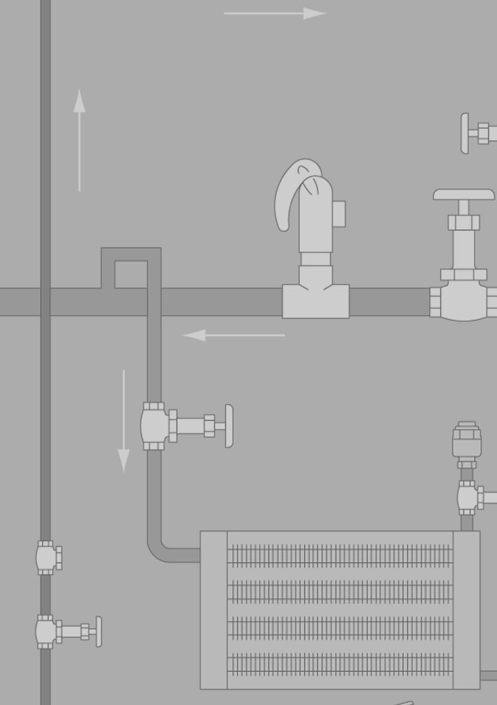
250

251 Steam Tracing Equipment
252 Armstrong Steam Tracing Equipment ID Chart Tabe STE Steam Tracing Equipment ID Chart Iustration Type Fow Direction Connection Type Max. Aow. Pressure barg TMA C Body Materia Mode Max. Oper. Pressure barg Number of Tracers Connection Size Located on Page TCMS Piston Vave Steam Tracing Equipment MSD and SMSD Manifods for Steam Distribution MCC-160 with TVS-5111 Condensate Coection Assemby Socketwed ASTM A216 TCMS 50 1/2" STE-189 Socketwed Buttwed Fanged Socketwed Buttwed Fanged ASTM A105 Forged Stee MSD-04 MSD-08 MSD-12 SMSD-04 SMSD-08 SMSD Inet and Drain: 1 1/2" Tracers: 1/2" 3/4" MCC Outet and ASTM A105 Drain: 1 1/2" MCC Forged Stee Tracers: 1/2" MCC /4" STE-190 STE-192 TVS-4000 Trap Vave Station Screwed Socketwed Fanged ASTM A351 Gr. CF8M TVS /2" 3/4" STE-194 Series 2000 Inverted Bucket Steam Trap Capacities to 590 kg/h Screwed Socketwed Fanged L Stainess Stee /2" 3/4" 1" STE-196 TVS-5000 Trap Vave Station Screwed Socketwed Fanged ASTM A350 LF2 TVS /2" 3/4" STE-198 CCA-203 with TVS Condensate Coection Assemby Mode AB-3000 Bimetaic Steam Trap Capacities to kg/h Socketwed Buttwed Fanged Screwed Socketwed Fanged ASTM A105 Forged Stee 304L Stainess Stee CCA CCA CCA CCA CCA AB Outet and Drain: 1 1/2" Tracers: 1/2" 3/4" 1/2" 3/4" 1" STE-200 STE-202 Mode CD-3300 Controed Disc Steam Trap Capacities to 360 kg/h Screwed Socketwed Fanged Stainess Stee CD /2" 3/4" 1" STE-203 Mode WT-2000 Thermostatic Wafer Steam Trap Cod Water Start-up Capacities to 730 kg/h Screwed Socketwed Fanged L Stainess Stee WT /2" 3/4" 1" STE-204 Mode TT-2000 Thermostatic Beows Steam Trap Capacities to kg/h Screwed Socketwed Fanged L Stainess Stee TT /2" 3/4" 1" STE-205 Operating pressure and temperature may be imited depending on the cass of fange seected. A modes compy with the Pressure Equipment Directive PED 97/23/EC. For detais, see specific product page or Armstrong PED Certificate. STE-186
253 Armstrong Simpifies Your Tracing Line Systems Designed to simpify and suppy a the components (steam traps, manifods, vaves, etc.) necessary for your drip and tracer ine appications, Armstrong s new Steam Distribution and Condensate Coection Manifods bring a components together to reduce instaation costs and provide a compact, easiy accessibe, centray ocated assemby. Armstrong s manifod series incudes four different configurations, a Steam Distribution (MSD/SMSD), and a Condensate Coection Assemby (CCA/CCAF). As an option, the condensate manifods can offer freeze protection. In either case, you wi save the expensive headaches of trying to fabricate in-house. What s more, your manifod wi be backed by the famous Armstrong quaity and a standard three-year imited warranty. Steam Distribution Manifods As a Steam Distribution Assemby (MSD/SMSD), the manifod paces a steam suppy vaves in one ocation. Standardizing components and centraizing their ocation simpifies instaation, cutting costs from the beginning. You aso save because routine maintenance is faster. Condensate Coection Manifods To make industry s trapping and vaving more efficient, Armstrong combines its stainess stee steam trap vave stations with manifods into a package caed the Condensate Coection Assemby (CCA). This prepackaged assemby offers many great benefits cost savings in instaation, design fexibiity, and reduced purchasing time. CCAF woud aso incude syphon tube freeze protection. Whatever your condensate coection or steam distribution needs, Armstrong has the manifod for savings over the ong term. Steam Tracing Equipment Steam Suppy from Boier To Product Lines ASIV Ambient Sensing Isoation Vave suggested ocation options Tracers ony Overhead Condensate Return Line To Condensate Return System CCA-208 Condensate Coection Assemby Shown are typica ocations for Armstrong manifods. The many manifods in chemica/petrochemica pants consume vauabe foor space and often bock movement among the units. Operating costs are high, and instaation requires expensive custom fabrication on site. Ceary, a prefabricated manifod permitting standardization of components offers substantia savings over conventiona units. Shaded products are avaiabe from Armstrong. Ca or consut your Armstrong Representative if additiona product detais are required. Spares Service Aey CSDV Condensate Sensing Drain Vave SMSD Steam Distribution Manifod TVS-4000 Trap Vave Station with 2000 Series Trap STE-187
254 The Proof Is in the Piston Steam Tracing Equipment Many of Armstrong s manifods utiize the piston vave because of its years of exceent performance in steam systems a over the word. The proof of Armstrong s ong service ife for manifods is in the piston. A types of vaves pug vaves, gate vaves, piston vaves and even ba vaves have been summoned for duty in steam service. Due to its exceent seaing characteristics in steam service, and because it has no gand packing, the piston vave is frequenty seected for steam systems. Peope who have used it over the past 90 years can testify that eakage to atmosphere is extremey rare, even without any The Piston Vave maintenance. The eastic contact between piston and vave seaing rings provides a perfect tightness, both in-ine and to atmosphere. Steam system vaves, whatever their design, are used to isoate steam and condensate ines or when a fauty steam trap needs to be removed from the ine. This means the vaves stay in the open position for ong periods and are neary aways in contact with the atmosphere. It is not surprising, therefore, that when the vaves need to be cosed, they can often prove difficut to operate. Our experience and the demands from end users for energy efficiency have ed us to a seaing system designed especiay for steam service. Stem Cap Stainess Stee Vave Pug Disc Springs Graphite and Stainess Stee Vave Seaing Rings Lantern Bushing Open Position Cosed Position Dua seaing action. The piston vave is a seatess vave that incudes two graphite and stainess stee vave seaing rings that sea the stem and function as a seat. This combination provides ong-term protection against eaks to the atmosphere and downstream piping. Sef-ceaning action. Stainess stee piston sides without rotating between the two vave seaing rings, preventing dirt from damaging the surfaces. Seaing integrity. Fexibe disc springs automaticay provide eak tightness by exerting pressure, which keeps the upper and ower vave seaing rings compressed at a times. Seaing tightness is ensured by the compression of the seaing rings against the piston and vave body. This combination of disc springs and dua vave sea rings protects against expansion and contraction due to heating and cooing. This ensures dependabe operation, even after years of service. Protected vave stem. The vave stem and seaing surfaces are competey protected from dirt and corrosion by the stem cap, whether in an open or cosed position. In-ine repairabiity. A seaing vave components may be easiy repaced in-ine. Long-term operation. Piston vave design ensures actuation even after many years without operation. STE-188

255 TCMS Piston Vave Armstrong TCMS is a carbon stee piston vave that has been designed for and perfecty adapted to steam appications. Features Rated ANSI Cass 300, C Inine seaing Externa tightness Reduced bore Easy to operate and maintain Bonnet and internas are interchangeabe with vaves used on Armstrong manifods and TVS Thus maintenance, purchase and stock management are easier and ess costy. Connections 1/2" SW Operating conditions: Maximum Design Pressure: 50 barg Maximum Design Temperature: 400 C Weight: 1,2 Kg Steam Tracing Equipment This mode compies with the Artice 3.3 of the PED (97/23/EC). Tabe STE Materia Specification Part Description Materia 1 Body ASTM-A216,WCB 2 Bonnet ASTM-A105 N 3 Vave stem Z6 CDF Lantern bush 304 STN.STL 5 Vave ring Reinforced graphite 6 Spring washer 17-4 STN.STL. 7 Washer 303 STN.STL. 8 Nuts ASTM-A194,Gr.2H 9 Studs ASTM-A193,Gr.B7 10 Handwhee Ductie iron 11 Washer fat 304 STN.STL. 12 Nuts 304 STN.STL. A dimensions and weights are approximate. Use certified print for exact dimensions. Design and materias are subject to change without notice. STE-189

256 MSD & SMSD Manifods for Steam Distribution As Steam Distribution Assembies (MSD/SMSD), the manifods pace a steam suppy vaves in one ocation. Standardizing components and centraizing their ocation simpifies instaation whie providing cost savings. You aso save because routine maintenance is faster. Insuation can aso be provided and can be a major savings in most instaations. Cost Savings Reduced design specification costs Prefabrication vs. fied assemby for easy instaation Reduced shipping and fied handing costs Lower ong-term maintenance and operating costs 3-years guarantee Steam Tracing Equipment Steam Inet Design Fexibiity Dimensiona consistency Space savings Insuation package avaiabe Fow Tracer Lines Typica SMSD steam distribution appication (shown with optiona nippes and TVS-4000 Trap Vave Station with 2000 Series Inverted Bucket Trap) STE-190

257 MSD & SMSD Manifods for Steam Distribution Steam Tracing Equipment Tabe STE MSD and SMSD List of Materias Name Materia Manifod Body ASTM A105 Forged Stee Handwhee Ductie Iron Bonnet ASTM A105 Forged Stee Spring Washer Stainess Stee Bots and Nuts Bots: ASTM A193 grade B7 Nuts: ASTM A194 grade 2H Piston & Stem 17% Chrome Stainess Stee Vave Seaing Rings Expanded Graphite & Stainess Stee Bushing, Vave Stainess Stee Options Top Inet: Socketwed Fanged DIN or ANSI Gate vave 1 1/2" SW or Fanged Armstrong RP-2000 doube seaed vave 1 1/2" SW or Fanged Drain: 1/2" or 3/4" SW reducer TCMS piston vave TVS-4000 with 2011 steam trap (horizonta or vertica piping) Insuation: Armstrong Insuation Jacket Moduar or 1 piece versions Insuation jackets coud be instaed without removing the handwhees Tabe STE MSD and SMSD Steam Distribution Manifods (dimensions in mm) Mode MSD Series SMSD Series MSD-04 MSD-08 MSD-12 SMSD-04 SMSD-08 SMSD-12 Number of tracers A Open Position B Manifod Height (SW) C C Lto CL D Drain Connection 1 1/2" SW 1 1/2" SW E Number of Hoes for Mounting (1/2-13 UNC) G Inet 1 1/2" SW 1 1/2" SW F Outet to tracer 1/2" and 3/4" Socketwed and Screwed NPT 1/2" and 3/4" Socketwed and Screwed NPT Weight in kg (SW) Maximum Operating Pressure C A MSD and SMSD modes are CE Marked according to the PED (97/23/EC). For TVS and traps, pease check the specific page. A dimensions and weights are approximate. Use certified print for exact dimensions. Design and materias are subject to change without notice. STE-191
258 MCC-160 Manifod Condensate Coection with TVS-5111 Steam Tracing Equipment Armstrong combines its Trap Vave Stations (TVS) concept with MSD manifods into a package caed the MCC-160 Condensate Coection Assemby. This prepackaged assemby offers many great benefits cost savings in assemby, design fexibiity and reduced purchasing and design time. The MCC-160 with TVS and 2000 Series Inverted Bucket Traps is guaranteed for 3 years. Cost Savings This preassembed concept offers tremendous savings by reducing mutipe component purchases that cause additiona purchase order monitoring and shipping costs. Other savings incude far ess abor time required for fied assemby. This moduar forged stee body design provides quick assemby/deivery, reducing overa project costs. Eiminates mutipe component purchases Reduced design specification costs Prefabrication vs. fied assemby for easy instaation Reduced shipping and fied handing costs Lower ong-term maintenance and operating costs 3-years guarantee TVS-5111 Concept Armstrong Traps Vave Stations (TVS) concept gives compact aternative to traditiona trap instaations incuding 4 vaves and a strainer. The universa connector aows easy instaation and repacement of traps using any of the existing operating principes. Armstrong TVS-5111 incudes: Upstream isoating piston vave Bowdown vave Test vave System Design Fexibiity Armstrong can meet virtuay any design parameter with your choice of socketwed or threaded connections. Inverted bucket, bimetaic, thermostatic beow, thermostatic wafer or disc steam traps can be provided. If you require a specific piping arrangement, Armstrong can offer the fexibiity to meet your specifications. A existing steam trap types coud be used Dimensiona consistency Space savings Insuation jacket avaiabe Tabe STE MCC-160 List of Materias Name Materia Manifod Body ASTM A105 Forged Stee Handwhee Ductie Iron Bonnet ASTM A105 Forged Stee Spring Washer Stainess Stee Bots and Nuts Bots: ASTM A193 grade B7 Nuts: ASTM A194 grade 2H Piston & Stem 17% Chrome Stainess Stee Vave Seaing Rings Expanded Graphite & Stainess Stee Bushing, Vave Stainess Stee Removabe Insuation Jackets A removabe insuation jackets are avaiabe for a steam and condensate manifods. Inexpensive Quick to insta Removabe for maintenance Reusabe after maintenance Weatherproof Formed to cover a manifod eements Strong, durabe cover Avaiabe to fit a manifod sizes STE-192
259 MCC-160 Manifod Condensate Coection with TVS-5111 F Inet Conn. Type Mounting THDS M14 x 2 H Outet 1 1/2 SW End Type D 1/2 SW Drain Conn. Type Tabe STE MCC-160 with TVS-5111 (dimensions in mm) Mode MCC MCC MCC Number of tracers A Vave, Open Position B Height C C L Inet to Outet D Connection, Bowdown 1/2" SW E C Lto C L F Connection Size 1/2" and 3/4" SW and Screwed NPT H Outet Connection 1 1/2" SW I Face to Face (with 2011 steam trap configuration) J Face to Face Weight in Kg (without traps) Maximum Operating Pressure C A MCC-160 modes are CE Marked according to the PED (97/23/EC). For traps, pease check the specific page. Steam Tracing Equipment Options Top Outet: Socketwed Fanged DIN or ANSI Gate vave 1 1/2" SW or Fanged Drain: 1/2" or 3/4" SW reducer TCMS piston vave Insuation: Armstrong Insuation Jacket Moduar or 1 piece versions Insuation jackets coud be instaed without removing the handwhees A dimensions and weights are approximate. Use certified print for exact dimensions. Design and materias are subject to change without notice. STE-193
260 TVS-4000 Stainess Stee Trap Vave Station Integra piston stye inet and outet isoation vaves Steam Tracing Equipment Connection fexibiity (SW, NPT, BSPT options) Armstrong connector adaptabe to inverted bucket, disc, thermostatic, thermostatic wafer, bimetaic, and foat and thermostatic steam traps. Any other manufacturer s 2-bot steam trap can aso be appied to Armstrong s TVS 4000 connector. 3-years guarantee Test vave used to test and evauate trap operation Strainer bowdown vave Description Same principe. Different package with two piston-stye isoation vaves, test vave and integra stainess stee strainer with bowdown vave. What you find new are a the benefits of a piston vave integrated into the same space-saving package. Maximum Operating Conditions Maximum aowabe pressure: C Materias TVS 4000 Connector Connector: ASTM A351 Gr. CF8M Strainer screen: Stainess stee Test vave: Stainess stee Bowdown vave: Stainess stee Isoation Vave Components A wetted parts: Stainess stee Vave seaing rings: Graphite and stainess stee Handwhee: Ductie iron Weight 2.9 kg Description Reduced costs. TVS saves on these fronts: reduced eak points, instaation and maintenance time. A fu range of features. TVS has test and strainer bowdown vaves. When instaed with Armstrong Mode 2011 and 2022 steam traps, it wi aso accommodate the Armstrong pop drain as we as TrapAert and SteamEye remote steam trap monitoring and testing devices. Reduced design time. Permits combining products with exact face-to-face dimensions. Three-year guarantee. The TVS 4000 is guaranteed for three years. Easy, in-ine repairabiity with maximum safety. TVS aows isoation at point of service with upstream/downstream depressurization. Instaation versatiity. The connector design makes the TVS adaptabe to any manufacturer s 2-bot steam trap and piping configuration. Simpified trap testing. TVS enhances your capabiity to check trap operation and offers a buit-in method to bock and beed traps. Tabe ST How to Order Mode Connection Type of Connection Inet/Outet Fow Direction Trap Type TVS /2" 3/4" NPT SW BSPT Fanged* R = Right to Left L = Left to Right Inverted Bucket Disc Thermostatic wafer Bimetaic Foat and Thermostatic *Consut factory. U.S. Patent 6,467,503 STE-194
 Spira-wound gasket 304 Stainess Stee corrosion resistant")
 Foat & Thermostatic (F&T-2000) Connections: Screwed NPT and BSPT Socketwed Fanged DIN and ANSI Steam Tracing Equipment Avaiabe with Standard Connector Materia: 304 Stainess Stee")
261 Armstrong 360 Universa Connector Since Armstrong has designed the first Universa Connector in 1982, this one has become a standard everywhere in the word. Features: Trap remains in the same position does not matter the pipe configuration Connectors remain in-ine for easy trap repacement (2 bots) Spira-wound gasket 304 Stainess Stee corrosion resistant construction Lightweight Optiona integras strainer (IS-2) A existing trap types: Inverted Bucket (2000 Series) Bimetaic (AB-3000) Thermodynamic (CD-3300) Thermostatic wafer (WT-2000) Thermostatic beows (TT-2000) Foat & Thermostatic (F&T-2000) Connections: Screwed NPT and BSPT Socketwed Fanged DIN and ANSI Steam Tracing Equipment Avaiabe with Standard Connector Materia: 304 Stainess Stee Avaiabe with IS-2 Integra Strainer Connector (shown with optiona bowdown vave) Materia: 316 Stainess Stee STE-195
 Optiona Upstream Bowdown Port Steam Tracing Equipment Mode TVS-4000 with 2000 series SS Trap Front View Mode TVS-4000 with")


262 TVS-4000 Stainess Stee Trap Vave Station Stainess Stee with 360 Connector For Pressures to 45 bar...capacities to 590 kg/h (Using 2000 Series Inverted Bucket Steam Traps) Optiona Upstream Bowdown Port Steam Tracing Equipment Mode TVS-4000 with 2000 series SS Trap Front View Mode TVS-4000 with 2000 series SS Trap Side View Test Vave Test Port Connection Test Vave Used to test and evauated trap operation Mode TVS-4000 with 2000 series SS Trap Bottom View Strainer Bowdown Vave Same principe. Different package with two piston-stye isoation vaves, test vave and integra stainess stee strainer with bowdown vave. Now the energy-saving performance and reiabiity of the inverted bucket steam trap are avaiabe in a versatie new package. You sti enjoy a the famiiar benefits. And the same efficient condensate drainage from virtuay every kind of steam-using equipment. What you find new are a the benefits of a piston vave integrated into the same space-saving package. Materias TVS-4000 Connector Connector: Strainer Screen: Screen Retainer: Gasket: Retainer Unit: Test Vave: Bowdown Vave: ASTM A351 Gr. CF8M Stainess stee Stainess stee Stainess stee Stainess stee Stainess stee Stainess stee Isoation Vave Components Handwhee: Nut : Stem, Washers: Bonnet: Bonnet, Bots: Vave Pug: Disc Springs: Vave Seaing Rings: Lantern Bushing: Vave Washers: Materias Series 2000 Traps Cast iron Stainess stee Stainess stee ASTM A351 Gr. CF8M Stainess stee Gr. A2 Stainess stee Stainess stee Graphite and stainess stee Stainess stee Stainess stee Body: ASTM A240 Gr. 304L Internas: A stainess stee 304 Vave and seat: Stainess Stee 17-4PH (<35 bar) Titanium (>35 bar) Connections Screwed BSPT and NPT Socketwed Fanged DIN or ANSI (weded) Tabe ST TVS-4000 Series with 2000 Series Inverted Bucket Steam Trap (dimensions in mm) Mode No Pipe Connections A Trap Diameter B Height Vave Open C Face-to-Face (screwed & SW) CC Face-to-Face (fanged PN40*) D Connection C L to Bottom E Connection C L to Outside of Trap F Connection C L to Front of Handwhee (Vave Open) G Connection C L to Top of Handwhee (Vave Open) H Connection C L to Bottom of Connector J Width Across Handwhees (Vave Open) Weight in kg (screwed & SW) 4,1 4,3 5,4 Weight in kg (fanged PN40*) 5,8 6,4 6,0 6,6 7,1 7,7 Maximum Operating Pressure (Trap) 14 bar 28 bar 45 bar Maximum Aowabe Pressure (Trap) C C C * Standard fanges are in carbon stee, stainess stee fanges are optiona. Other fange sizes, ratings and face-to-face dimensions are avaiabe on request. A modes compy with the artice 3.3 of the PED (97/23/EC). May be derated depending on fange rating and type. A dimensions and weights are approximate. Use certified print for exact dimensions. Design and materias are subject to change without notice. STE-196
 Tabe ST-197-1. Mode 2010 Capacity Tabe ST-197-2.")


263 TVS-4000 Stainess Stee Trap Vave Station Stainess Stee with 360 Connector For Pressures to 45 bar...capacities to 590 kg/h (Using 2000 Series Inverted Bucket Steam Traps) Tabe ST Mode 2010 Capacity Tabe ST Mode 2011 Capacity Capacity, kg/h Steam Tracing Equipment Pressure, bar Tabe ST Mode 2022 Capacity Options Insu-Pak Now you can insuate the in-ine traps in your pant without compicating reguar trap maintenance. Insu-Pak, a simpe reusabe insuation package, cuts the time and cost of in-fied instaation because it goes on in a snap. And it comes off just as easiy. The Insu-Pak can prevent trap freeze-up when used with a propery designed condensate manifod. Designed for use with Mode 2010 and Mode 2011 traps. Capacity, kg/h Capacity, kg/h Pressure, bar Tabe ST How to Order Mode Connection Type of Connection Inet/Outet Fow Direction Trap Type TVS NPT SW BSPT Fanged R = Right to Left L = Left to Right Inv. Bucket Disc Thermostatic Bimetaic F&T Pressure, bar Pop Drain Simpe but effective against freeze-up. Propery instaed and maintained at ow points in your system, the simpe, pressure-actuated pop drain opens for condensate drainage at 0,35 barg for Modes 2011 and Probe Connections are avaiabe for trap monitoring on Modes 2011 and Pop Drain A dimensions and weights are approximate. Use certified print for exact dimensions. Design and materias are subject to change without notice. STE-197
264 TVS-5000 Series Forged Stee Trap Vave Station Integra piston stye inet and outet isoation vaves Steam Tracing Equipment Connection fexibiity (SW, NPT, BSPT options) Armstrong connector adaptabe to inverted bucket, disc, thermostatic, thermostatic wafer, bimetaic, and foat and thermostatic steam traps. Any other manufacturer s 2-bot steam trap can aso be appied to Armstrong s TVS connector. Test vave used to test and evauate trap operation Bowdown vave Mode shown TVS-5211 Description Armstrong s TVS-5000 is designed as a one piece body equipped with a piston vave(s) combined with a removabe steam trap mounted with a connecting fange. Maximum Operating Conditions Maximum Aowabe Pressure : C Maximum Aowabe Temperature : 315 C Maximum Operating Pressure : 45 bar Maximum Hydrostatic Pressure : 68 bar Materias TVS-5000 Connector Connector: Test vave: Bowdown vave: ASTM A350 LF2 ASTM A582 T303 ASTM A582 T303 Weight 3, 660 kg (without any trap) Features Reduced costs. TVS-5000 saves on these fronts : reduced eak points, instaation and maintenance time. Reduced design time. Permits combining products with exact face-to-face dimensiosn. Easy, in-ine repairabiity. Simpified trap testing. TVS enhances your capabiity to check trap operation and offers a buit-in method to bock and beed traps. Isoation Vave Components Vave seaing rings : Graphite & Stainess Stee Bonnet : ASTM A350 LF2 Bots : DIN Vave pug : ASTM A H900 Lantern bushings : ASTM A582 T304 Vave washer : ASTM A582 T304 Disc springs : AISI T301 Nut : AISI T304 Handwhee : Ductie Iron May be derated depending on fange rating and type. STE-198
265 TVS-5000 Series Forged Stee Trap Vave Station Tabe ST How to Order Mode Connection Type of Connection Inet/Outet Fow Direction Trap Type TVS /2" 3/4" NPT SW BSPT Fanged* R = Right to Left L = Left to Right Inverted Bucket Disc Thermostatic wafer Bimetaic F&T *Consut factory. J Tabe ST TVS-5000 Series TVS-5211 Trap Vave station mounted with 2011 Steam Trap Pipe Connections G D H A A Trap Diameter 68 C Face to Face (screwded NPT and socketweded modes) 122 D Connection CL to bottom 99 E Connection CL to Outside of Trap 117 F Connection CL to Front of Handwhee (Vave Open) 98 G Connection CL to Top of Handwhee (Vave Open) 108 H Connection CL to Bottom of Connector 143 J Width Across Handwhees (Vave Open) 270 Steam Tracing Equipment F Pressures and capacities depending on the steam trap mounted on the Trap Vave Station. C Materias TVS-5000 Connector Connector: Test vave: Bowdown vave: ASTM A350 LF2 ASTM A582 T303 ASTM A582 T303 E Armstrong Internationa SA Parc Industrie des Hauts-Sarts (2e Avenue) 4040 Hersta Begium STE-199
 Armstrong combines its Trap Vave Stations (TVS) with manifods into a package caed the CCA-203")
266 CCA-203 Condensate Coection Assemby with TVS Optiona steam-jacketed syphon ift tube adds freeze protection Steam Tracing Equipment Optiona Armstrong CSDV Vave CCA with TVS-4000 (shown with optiona nippes, drain vave and TVS-4000 with 2000 Series Inverted Bucket a stainess stee steam traps) Armstrong combines its Trap Vave Stations (TVS) with manifods into a package caed the CCA-203 Condensate Coection Assemby. This prepackaged assemby offers many great benefits cost savings in assemby, design fexibiity and reduced purchasing and design time. The CCA-203 with TVS or TVS-5000 guaranteed for 3 years. Cost Savings This preassembed concept offers tremendous savings by reducing mutipe component purchases that cause additiona purchase order monitoring and shipping costs. Other savings incude far ess abor time required for fied assemby. This moduar forged stee body design provides quick assemby/deivery, reducing overa project costs. Eiminates mutipe component purchases Reduced design specification costs Prefabrication vs. fied assemby for easy instaation Reduced shipping and fied handing costs Lower ong-term maintenance and operating costs 3-years guarantee Design Fexibiity Armstrong can meet virtuay any design parameter with your choice of socketwed or threaded connections. Inverted bucket, bimetaic, thermostatic beow, thermostatic wafer or disc steam traps can be provided. If you require a specific piping arrangement, Armstrong can offer the fexibiity to meet your specifications. A existing steam trap types coud be used Dimensiona consistency Space savings Freeze protection option Insuation jacket avaiabe Materias Manifod body: ASTM A105 forged stee A Stainess Stee 304L avaiabe on request Freeze Protection Package (CCAF) Optiona A manifod assemby for more efficient condensate return has another benefit freeze protection. Armstrong s innovative manifod design actuay serves as a heat station, heating one or more traps if the steam suppy is interrupted or shut off to the traps. The protection is accompished as ong as one trap continues to discharge into the manifod. The manifod s interna syphon tube creates a water sea, which contains the fash steam from the discharge of the ive trap. This aows radiant heat to protect shut-off traps from freezing. An optiona freeze protection vave package senses condensate temperature. When this device opens, it drains condensate from the manifod assemby, thus providing further freeze protection. Removabe Insuation Jackets A removabe insuation jackets are avaiabe for a steam and condensate manifods. Inexpensive Quick to insta Removabe for maintenance Reusabe after maintenance Weatherproof Formed to cover a manifod eements Strong, durabe cover Avaiabe to fit a manifod sizes STE-200
267 CCA-203 Condensate Coection Assemby with TVS Steam Tracing Equipment Optiona 1/2" TCMS Drain Vave Optiona steam-jacketed syphon ift tube adds freeze protection Optiona Freeze Protection Improves condensate fow inside of the manifod s body, thus giving better protection against freezing. CCA with 6 x TVS-4000 Trap Vave Station with 2000 Series Inverted Bucket Traps Tabe STE CCA-203 Condensate Coection Assemby (dimensions in mm) Mode CCA CCA CCA CCA CCA Number of tracers B Manifod Height (SW) Drain Connection 1 1/2" SW Manifod Outet 1 1/2" SW TVS Connection 1/2" and 3/4" Socketwed and Screwed NPT Weight in kg (manifod ony) Maximum Aowabe Pressure C A CCA-203 modes are CE Marked according to the PED (97/23/EC). TVS-4000 compies with the Artice 3.3 of the same directive. For traps, pease check the specific page. Options Top Outet: Socketwed Fanged DIN or ANSI Gate vave 1 1/2" SW or Fanged Drain: 1/2" or 3/4" SW reducer TCMS piston vave Insuation: Armstrong Insuation Jacket Moduar or 1 piece versions Insuation jackets coud be instaed without removing the handwhees A dimensions and weights are approximate. Use certified print for exact dimensions. Design and materias are subject to change without notice. STE-201
268 AB-3000 Bimetaic Steam Trap Stainess Stee For Pressures to 22 bar Capacities to kg/h Steam Tracing Equipment Description Armstrong's AB-3000 Bimetaic Steam Trap operates by the effect that rising temperature has on bimetaic eements. It adjusts itsef to changing conditions, as the increasing pressure on the vave is compensated by the curving of the bimetaic eements caused by the increasing temperature. The vave of the AB-3000 is speciay treated (boronization) in order to be more resistant to wiredrawing due to erosive condensate fashing. Armstrong's AB-3000 has a seaed, stainess stee body that is ightweight, compact and highy resistant to corrosion. The AB-3000 is repairabe (body and cap can be unscrewed). It is piped through the Armstrong 360 Universa Connector or Trap Vave Station (TVS). This makes it easy to insta and repace, as the trap can be removed whie the connector remains in-ine. The resut is savings in abor cost and increasing in fexibiity, as other trap types (Inverted Bucket, Thermostatic and Thermodynamic) can be instaed on the same connector. Vave Boronized The probem of wiredrawing of vave and seat materias is we known to users of steam traps and other types of vaves. Wiredrawing is a particuar probem to vaves and seats of bimetaic traps, which rey on bimetaic eements to operate. To sove the probem of wiredrawing, a new thermochemica surface treatment has been deveoped. The basic vave materia is machinabe hardened chrome stee. Atoms of highy resistant materia are thermochemicay diffused into the vave, giving a ayer of protection and a hardness of 1700 HV to the basic materia. Because of this new thermochemica treatment, the surface of the vave is highy resistant to the erosive action of fashing condensate. The faiure rate of Armstrong bimetaic traps due to wearing out of vave and seat materia is greaty reduced. Tabe ST Mode AB-3000 Trap (dimensions in mm) Pipe Connections C Face-to-Face (screwed & SW) N/A CC Face-to-Face (fanged PN40*) Weight in kg (screwed & SW) 1,9 Weight in kg (fanged PN40*) 4,3 4,5 4,7 * Standard fanges are in carbon stee, stainess stee fanges are optiona. Other fange sizes, ratings and face-to-face dimensions are avaiabe on request. A sizes compy with the artice 3.3 of the PED (97/23/EC). Maximum operating conditions Maximum aowabe pressure (vesse design) : C Maximum operating pressure: 22 bar Maximum back pressure: 99% of inet pressure Connections Screwed BSPT and NPT Socketwed Fanged DIN or ANSI (weded) Materias Body: ASTM - A L Standard connector: Stainess stee 304 Vave: Chrome stee 440F, Boronized Seat: 303 Stainess stee Eements: Nicke pated Strainer: 304 Stainess stee Specification Bimetaic repairabe steam trap with vave boronized, type AB-3000 in stainess stee, with integra strainer. Piped through 360 Universa Connector or Trap Vave Station (TVS). Maximum aowabe back pressure 99% of inet pressure. How to order Specify: Size and type of pipe connection. Maximum working pressure that wi be encountered Maximum condensate oad Tabe ST Mode AB-3000 Capacity Capacity, kg/h May be derated depending on fange rating and type. A = Cod Water B = 40 C Beow Saturation Pressure, bar C = 20 C Beow Saturation D = 10 C Beow Saturation A dimensions and weights are approximate. Use certified print for exact dimensions. Design and materias are subject to change without notice. STE-202
269 CD-3300 Disc Steam Trap A Stainess with 360 Connector For Pressures to 31 bar Capacities to 360 kg/h Optiona Rain Guard CD-3300 with Standard Connector Tabe STE CD-3300 Series Capacity Steam Tracing Equipment The Armstrong CD-3300 is a three discharge port design, which provides stabe disc operation to extend operating ife. The CD-3300 is piped in-ine by a 360 universa connector which aows you to insta the trap in virtuay any piping configuration. Armstrong s unique standard connector or its IS-2 connector with integra strainer makes the CD-3300 easy to insta, easy to renew. You save on abor time and cost because the connector simpifies piping and remains in-ine. Materias Trap and cap: ASTM A743 CA40 Trap disc: ASTM A276 Gr.420 Trap body: ASTM A276 Gr.420 Standard connector: Stainess stee 304 IS-2 connector with integra strainer: ASTM A351 Gr.CF8 20 x 20 mesh 304 SS Screen Connections Screwed BSPT and NPT Socketwed Fanged DIN or ANSI (weded) 50 mm Withdrawa Length Optiona Bowdown Vave CD-3300 with IS-2 Connector with Integra Strainer Capacity, kg/h Pressure, bar Note: CD traps can operate with minimum of 0,15 bar inet pressure and a maximum of 80% back pressure. However, for best resuts, inet pressure shoud not drop beow 0,70 bar and back pressure shoud not exceed 50% of inet pressure. Options Rain guard insuating cap Bowdown vave IS-2 connector ony Tabe STE Mode CD-3300 Trap (dimensions in mm) Mode No. CD-3300 Standard Connector IS-2 Connector w/integra Strainer Pipe Connections C Face-to-Face (screwed & SW) N/A CC Face-to-Face (fanged PN40*) L Overa Length H Overa Height F C L to Body End Bowdown Connection Size 1/4" NPT 1/4" NPT Weight in kg (screwed) 1,6 1,8 2,0 Weight in kg (fanged PN40*) 3,3 3,9 4,4 3,5 4,1 4,8 Maximum Aowabe Pressure C Maximum Operating Pressure C * Standard fanges are in carbon stee, stainess stee fanges are optiona. Other fange sizes, ratings and face-to-face dimensions are avaiabe on request. A sizes compy with the artice 3.3 of the PED (97/23/EC). May be derated depending on fange rating and type. A dimensions and weights are approximate. Use certified print for exact dimensions. Design and materias are subject to change without notice. STE-203


270 WT-2000 Thermostatic Wafer Steam Trap Stainess Stee or Carbon Stee For Pressures to 41 bar...cod Water Start-Up Capacities to 730 kg/h Steam Tracing Equipment 50 mm Withdrawa Length Mode WT-2000 with IS-2 Connector with Integra Strainer Mode WT-2000 with Standard Connector Description The WT-2000 does not have an interna strainer, but is equipped with a specia 360 connector to expand piping options and simpify instaation. Choice of NPT or BSPT screwed connections, or socketwed connections. Aso avaiabe with optiona IS-2 stainess stee connector with integra strainer. Note: Since the norma operation of a suppressed temperaturedischarge (subcooing) steam traps is to back up condensate, they shoud not be used on drip egs for saturated steam service, heating or process equipment. Exercise care in the maintenance of any thermostatic wafer trap with a sma discharge area susceptibe to cogging. Specification Thermostatic wafer steam trap, type WT-2000 in stainess stee. Maximum aowabe back pressure 99% of inet pressure. Tabe STE WT-2000 Design Weded Screwed BSPT and NPT Connections Socketwed Fanged Materia Body ASTM A L Cap Capsue wafer Hasteoy Capsue body Stainess Stee 303 Capsue cap Connector Standard Stainess Stee 304 ASTM A351 Gr.CF8 IS-2 w/integra strainer w/20x20 mesh 304 SS screen Maximum operating conditions Maximum aowabe pressure C (vesse design) Maximum operating pressure 22 bar Options Bowdown Vave IS-2 Connector Ony Maximum back pressure: 99% of inet pressure May be derated depending on fange rating and type. How to Order Specify: Mode number Size and type of pipe connection, or connector stye Any options required Connectors Besides the inverted bucket traps, the standard connectors or IS-2 connector with integra strainer can aso be used on thermostatic, thermostatic wafer and controed disc traps. Tabe STE WT-2000 Capacity Differentia Pressure* Cod Water Start-Up 21 C Tabe STE WT-2000 Trap (dimensions in mm) Mode No. Hot Water Start-Up 100 C Standard Connector Operating Condensate 10 C Beow Saturation bar kg/h kg/h kg/h** 0, ,5 0, ,9 1, ,2 2, ,1 3, ,9 3, ,8 5, ,6 7, ,9 10, ,1 14, ,9 17, ,7 21, ,4 24, ,6 28, ,8 * Capacities based on differentia pressure with no back pressure. ** Capacities wi vary with the degree of subcooing. When greater capacities are required, the trap wi automaticay adjust to the oad, up to the maximum (cod water) capacity shown, by increasing the amount of subcooing. IS-2 Connector with Integra Strainer Pipe Connections A Diameter C Face-to-Face (screwed & SW) N/A CC Face-to-Face (fanged PN40*) F C L to Bottom End E Overa Length L Overa Height Bowdown Connection 1/4" 1/4" Weight in kg (screwed & SW) 1,4 1,5 1,5 Weight in kg (fanged PN40*) 3,8 4,0 4,2 3,2 3,8 4,3 * Standard fanges are in carbon stee, stainess stee fanges are optiona. Other fange sizes, ratings and face-to-face dimensions are avaiabe on request. A sizes compy with the artice 3.3 of the PED (97/23/EC). A dimensions and weights are approximate. Use certified print for exact dimensions. Design and materias are subject to change without notice. STE-204

271 TT-2000 Thermostatic Beows Steam Trap A Stainess Stee For Pressures to 20 bar...capacities to kg/h Description The baanced pressure beows thermostatic steam trap has a seaed, stainess-stee body that is ightweight, compact and highy resistant to corrosion. The cage, beows, vave and seat are a assembed into a precisey caibrated operating unit that ensures positive opening and cosing action at sighty beow steam temperature. The unique, stainess-stee construction is smaer and much ighter than comparabe cast iron, brass or stee traps. TT-2000 with the 360 universa stainess stee connector comes with either a standard connector or the IS-2 connector with integra strainer. Note: Can aso be used as a thermostatic air vent (Reference TTF Series Thermostatic Air Vents page AV-420). Specification Thermostatic steam trap, type TT-2000 in stainess stee. Maximum aowabe back pressure 99% of inet pressure. How to Order Specify: Mode number Size and type of pipe connection Connector type Connections Screwed BSPT and NPT Socketwed Fanged DIN or ANSI (weded) 50 mm Withdrawa Length Mode TT-2000 with IS-2 Connector with Integra Strainer Mode TT-2000 with Standard Connector Materias Body: Connector: Beows: Mode TT-2000 with Standard Connector Tabe STE TT-2000 Design Connections Materia Body Vave Seat Weded Screwed BSPT and NPT Socketwed Fanged ASTM A L Bronze Stainess Stee Standard Stainess stee & bronze Thermostatic air vent w/phosphor bronze beows caged in stainess stee Optiona: A stainess stee thermostatic air vent Connector Standard Stainess stee 304 ASTM A351 Gr.CF8 IS-2 w/integra strainer w/20x20 mesh 304 SS screen Maximum Operating Conditions Max. aowabe pressure C (vesse design) Max. operating pressure 20 bar Max. operating temperature beows 190 C Maximum back pressure: 99% of inet pressure 304L Stainess stee 304 Stainess stee Stainess stee and bronze with phosphor-bronze beows, caged in stainess stee Tabe STE Mode TT-2000 Capacity Steam Tracing Equipment Tabe STE TT-2000 Trap (dimensions in mm) Standard Mode No. Connector IS-2 Connector with Integra Strainer Pipe Connections A Diameter C Face-to-Face (screwed & SW) N/A CC Face-to-Face (fanged PN40*) E Overa Length F C L to Body End L Overa Height Weight in kg (screwed & SW) 1,4 1,5 1,5 Weight in kg (fanged PN40*) 3,8 4,0 4,2 3,2 3,8 4,3 * Standard fanges are in carbon stee, stainess stee fanges are optiona. Other fange sizes, ratings and face-to-face dimensions are avaiabe on request. A sizes compy with the artice 3.3 of the PED (97/23/EC). May be derated depending on fange rating and type. Capacity, kg/h 10 C subcooing Pressure, bar A dimensions and weights are approximate. Use certified print for exact dimensions. Design and materias are subject to change without notice. STE-205

 Removabe for maintenance Reusabe after maintenance Weatherproof Strong, durabe cover increase service ife Maximum")
272 Insuation Jackets for Manifods Manifod Type Jacket MSD or SMSD Pease specify: - distance between tracers 162 or 120 mm - number of tracers 4, 8, 12 ONE PIECE MODULAR CCA Pease specify: - number of tracers 4, 6, 8, 10, 12 Steam Tracing Equipment exampe range A removabe insuation jackets are avaiabe for a steam and condensate manifods. This incudes aso the condensate return manifods assembed with Trap Vave Stations (TVS) and steam traps. Features Inexpensive Safe Quick and easy to insta (no specia knowedge is required) Removabe for maintenance Reusabe after maintenance Weatherproof Strong, durabe cover increase service ife Maximum operating conditions Maximum operating temperature: 260 C Fame resistance: BS 476 Part 7, Cass 1 Materias Base fabric: Weave: Coating: Fibergass Satin Siver siicone rubber A dimensions and weights are approximate. Use certified print for exact dimensions. Design and materias are subject to change without notice. STE-206
273 Notes Steam Tracing Equipment STE-207
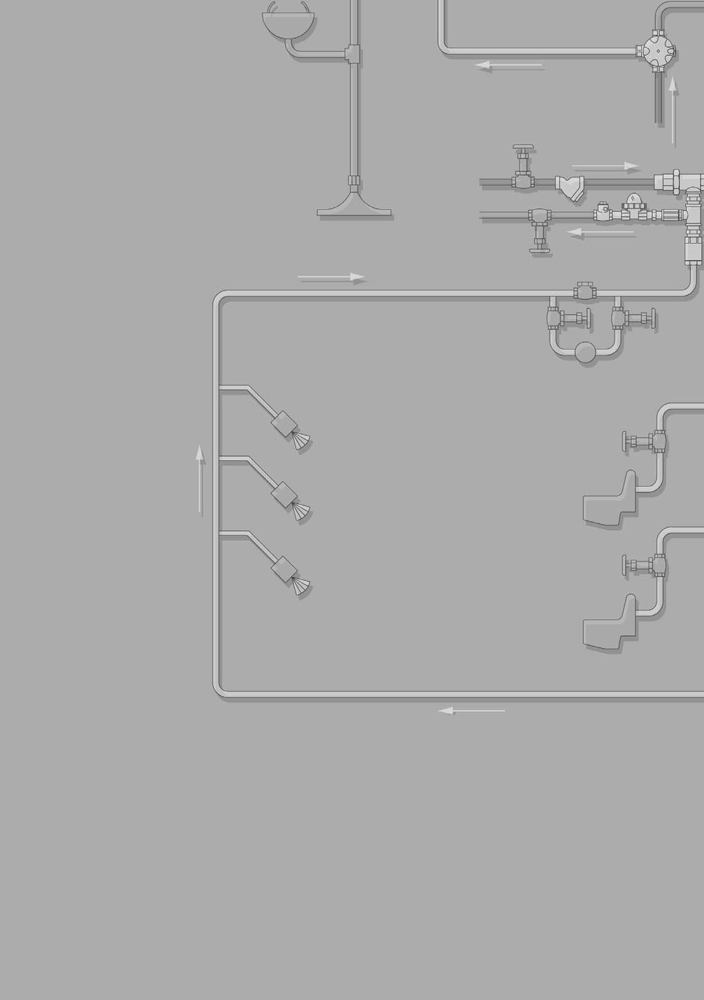
274

275 Steam Trap Management Products and Services


276 The New Standard for Steam Trap Management According to the Aiance to Save Energy, faciities have saved as much as 17% of fue use when impementing energy-saving processes. Estabishing a consistent, ong-term steam trap management process is one way to achieve savings. Steam Trap Management Historica Approach to Steam Trap Program* Trap inspections are typicay performed one time per year. The probem with this approach is that steam traps fai every day. These undetected faiures ead to system irreguarities, which, when eft undetected ong enough, can resut in severe probems and equate to important financia osses. Historica approach Proactive Approach to Best Practice Steam Trap Management* Eary detection means being abe to act on a trap faiure before the associated probem becomes severe. Therefore, immediate evauation of the situation and measurement of the resuts are critica for continued best practice process improvement, yeary steam oss reductions and sustained monetary savings. Proactive view Historica approach Severity Event detection Decision Action Severity Diagnostic and decision Action Event detection Operators receive indication of abnorma situation BEFORE event is critica+ Decision Action Time Time *Schavey, L. and Stout, J., "Achieving Operationa Exceence in Gas Pants," Hydrocarbon Processing, January Wireess, Labor-free, Instant Notification of Steam Trap Faiure! If you were to describe your vision for steam trap best practice, what woud it ook ike? Awareness The abiity to constanty monitor the steam trap popuation without abor aocation Instant notification of steam trap faiure Action Quick diagnosis and action on best trap repacement based on return on investment (ROI) Instant notification of steam trap faiure and a sustained (24/7) monitoring process. Accountabiity A reporting system that provides tracking, measurement, ROI anaysis and easy company-wide communication SteamEye and SteamStar bring steam savings through instant notification of steam trap faiure. SteamEye is the too to reduce abor and energy costs by constanty monitoring the steam trap popuation. SteamStar is the measurement software that wi create company-wide awareness for a a whoe new eve of steam savings. When working together, SteamEye wi feed the momentto-moment steam trap data into SteamStar. SteamStar wi instanty report this information through Web-based software that aows easy access for company personne to make timey, money-saving decisions. Company-wide awareness and mea surement of steam trap performance for ROI decision making. ST-174
277 SteamStar Easy-to-use and Very Affordabe Steam Trap Software SteamStar is the first Web-based software for recording, monitoring and managing steam trap information. SteamStar Web-based software can Improve steam system efficiency. Steam system efficiency can be directy inked to how we the system is managed. SteamStar provides diagnostic reporting at various eves of organizationa responsibiity. The reports permit the evauation of current conditions and provide the knowedge necessary to make money- saving decisions. Achieve best practice energy management goas. History has shown that companies maximize sustainabe cost savings when energy goas are measured, monitored, and managed on a consistent basis. SteamStar is the Web-based too that wi bring data together by site, by region and by company to hep achieve best practice energy management goas. Save vauabe time. Typicay steam trap data are presented from mutipe sites in different software formats and with different quaifying terminoogy. These variabes make managing steam system information difficut and time-consuming. SteamStar offers a patform for company-wide steam data to be viewed and anayzed without wasted time. Eiminate costs associated with software. icensing agreements. Licensing agreements can cost tens of thousands of euro for initia software purchase. For the software to faciitate mutipe users, additiona capita outay is required. The Web-based patform of SteamStar eiminates icensing fees and dramaticay reduces the required investment. A one month return on investment! Improve company-wide communication. Users at the pant eve can perform evauations to determine root cau ses of steam system issues. Using the same patfor, the goba energy manager has the abiity to anayze data for sites around the word. This eve of communication promotes understanding of steam system efficiency. Steam Trap Management Screen shot of SteamStar home page. ST-175

278 SteamStar Easy-to-use and Very Affordabe Steam Trap Software Steam Trap Management SteamStar Web-based software wi evauate steam system data. Continuous Steam Trap Monitoring captures rea time steam trap operation from SteamEye. SteamEye is the automated steam trap monitoring too that provides accurate and constant information from each steam trap. This information is transated by SteamStar into actio nabe reports. A of the reports avaiabe in SteamStar are designed for best practice measurement. Executive Summary Steam and Monetary Loss Defective Trap Report Manufacturer Summary Trap Evauation by Appication Screen shot of executive summary. Company Benchmarking This premium report estabishes a comparison to sister sites and industry peer best practices. The user has a choice of which sites to benchmark and which factors to compare. Steam osses and monetary osses can be compared by site, by type of appication, by type of trap, and more. This report wi offer management a wide anaysis of which sites are working to reduce steam osses and which ag behind. It wi aso highight any areas of concern in terms of high steam trap faiure rate compared to tota monetary osses. This report is a vauabe too for faci ity managers and goba energy managers aike. Prioritized Work Orders The work order report is a premium report that was designed for optimum faciity payback on abor and materia whie keeping energy osses to a minimum. This report is avaiabe at the site or unit eve and wi create a work order for steam trap repairs based on payback. Trend History The premium trend anaysis report wi assist a manager with the comparison of mutipe years of data. The data avaiabe for comparison are steam oss, monetary oss, fue consumed, and emissions created. Like the other premium reports, the trend anaysis report can be compared by site and/or region. It wi aso track emissions CO2, SOx, NOx and highight the progress made toward steam system efficiency and doars saved. Emissions Summary The premium emissions report is vauabe for its abiity to focus on the quantifiabe emissions of CO2, SOx, and NOx in one summarized view. Steam system efficiency is not ony viewed as important in terms of energy osses but aso in terms of environmenta impact. The emissions report is especiay beneficia to users that are penaized by word governments for high emission factors. Prioritized Work Order Screen shot of prioritized work order. Upoad your current steam trap information easiy, regardess of current format! ST-176


279 SteamEye -The Ony 24/7, Wireess, Labor-free Steam Trap Monitoring System! SteamEye can monitor any manufacturer's trap and any trap type. Steam Trap Management "It's ike having a man sitting there watching traps a day." That's how a maintenance supervisor at an instaation summed up the benefits of SteamEye. But exacty how does SteamEye do what it does? And how does it use radio waves to signa a rea beginning in steam system optimization? What is radio frequency (RF) steam trap monitoring anyway? Radio frequency monitoring of steam traps gives you an instantaneous insight into trap performance that is the most accurate measure of steam trap status avaiabe. The system consists of a transmitter, a repeater (if necessary), and a receiver. Buiding automation system integration is aso an option. Consut your Armstrong Representative or Armstrong's Appication Engineering Department. SteamEye saves energy and money Whoever first observed "Litte things mean a ot" perhaps had faied steam traps in mind. Show us a steam trap bowing through (osing steam), and we' show you potentia for huge savings in the amounts you spend for energy to generate steam in the first pace. Besides, ess energy consumed means ess waste, fewer emissions and a heathier environment. As you see from the tabe beow, a itte steam eak can truy be the start of something big. A singe trap with an 1/8-inch orifice can squander more than 4,000 per year. Mutipy that by the number of traps represented in a typica 20% faiure rate, and you begin to get the idea. Faied steam traps waste energy and cost you money. Big money. But that was then. Now there's SteamEye. What does an undetected faied steam trap cost? At today's energy prices, steam trap bow-thru can no onger be toerated. Energy ost means doars ost. In addition to energy osses, do not forget the other costs associated with undetected steam trap faiure. Critica processes, possibe oss of product Pressurized return ines Faiure to other equipment such as eectric condensate pumps, PRVs and contro vaves Unexpected downtime Emergency abor requirements Tabe ST Cost of Various Sized Steam Leaks (assuming steam costs of 20/t) Pressure Orifice Steam Loss Euro Loss per Year (barg) 500 Traps 20% Faiure Rate 1 3/16'' ,5 5/32'' ,5 1/8'' # /8'' /64'' NOTE: Steam oss based on bi-phase fow through an orifice using Armstrong s steam oss formua, approved by the United Nations Technica Committee. ST-177
280 SteamEye Proven Technoogy Steam Trap Management The SteamEye System Radio frequency technoogy has been around for decades. Armstrong Internationa has taken this technoogy, combined it with our 100 years of steam trap experience and deveoped a product to accuratey determine the operationa condition of any type, make and mode of steam trap without a abor requirement. Each transmitter is equipped with an eectronic board. This board houses the engineered "thought process" that gives SteamEye its reiabiity and accuracy. The Utrasonic transmitter uses a unique Armstrong designed Waveguide that concentrates the operationa sound of any steam trap to the eectronic board of the transmitter. The "thought process" of the eectronic board "istens" to the trap operation and determines precisey whether a trap is operating normay or is in a bow-thru state. In addition to the bow-thru condition, the transmitter have the abiity to sense when a trap is cod. To eiminate fase readings on moduating steam appications, the Utrasonic moduating transmitter wi check to see if pressure exists before sending a cod aarm. SteamEye How It Works The transmitter sends a radio frequency signa indicating the status of the steam trap back to a Web-enabed receiver. The Web-enabed receiver is connected to your company network running the SteamStar Web-based software. Information regarding a steam trap's operating condition (OK, bow-thru or cod) can be viewed with this software. Because SteamEye and SteamStar are inked through the network, users from various areas in the faciity can see the rea-time trap status. What is the typica range of the RF signa? In appications where the transmitter is ocated within the ine of sight of the receiver, the range is approximatey 400 meters. In faciities where the signa must trave through was or foors, the range varies. The typica range of the signa is approximatey 100 meters. If the receiver is out of the range of a transmitter, devices caed repeaters can be paced between the transmitter and the receiver to "repeat" the signa from one device to the next. A transmitter signa can pass through up to seven repeaters. Since it is difficut to know the range of a transmitter in a faciity, a radio-frequency-signa-strength survey wi determine if repeaters shoud be used and how many wi be required. Typica Pant Layout 400 m 400 m Let's face it: At any given time a percentage of your traps have faied, and you just don't have the manpower to check them frequenty. Besides, the trap you check on Tuesday afternoon may fai Wednesday morning and not be schedued for a recheck for months, even years. You just have to put up with a certain percentage of faiure, right? Wrong. Not any more. That's precisey the point of SteamEye. Trap with Transmitter Repeater Computer with Receiver SteamEye wi Monitor traps 24 hours a day, 365 days a year using a radio frequency signa Aert immediatey when a steam trap has faied, mitigating steam oss Protect critica process from steam trap faiure Eiminate frozen cois caused by pugged traps Hasten probem soving in areas where incorrect size or type of trap is used in specific appications Eiminate abor associated with testing traps Work in conjunction with a buiding automation system (BAS) A dimensions and weights are approximate. Use certified print for exact dimensions. Design and materias are subject to change without notice. ST-178


281 SteamEye Transmitter Choices The Utrasonic 3700 Series transmitter is used for appications at 2 bar or above. In addition, each series transmitter has two operating designs, constant pressure and on/off. The constant pressure transmitter is used on steam traps where steam is "on" at a times. The on/off transmitter shoud be used in appications where steam pressure is not constant. An exampe of an on/off appication woud be a batch process: steam pressure is required when the process is running, and steam is vaved off when there is no batch being run. The purpose of the on/off transmitter is to eiminate a fase cod signa due to no steam pressure. The on/off transmitter provides a connection aowing the unit to be tied to a pressure or position switch that indicates whether the system is pressurized. RFC3300 Utrasonic RFM3700 Transmitter Steam Trap Management With SteamEye and SteamStar, Energy Management Is Right at Your Desk As we have seen, the SteamEye system is your window into the inner workings of your steam trap popuation. You can aso use the SteamStar patform for data management. As a resut, you can buid a remarkaby versatie database of trap operating history. Screen shot of SteamStar home page. Screen shot of SteamStar survey page. Screen shot of SteamStar event history page. ST-179
282 SteamEye Dimensiona Drawings F F F Steam Trap Management E E E Series 800PC Trap with SteamEye Utrasonic Transmitter F&T Trap with SteamEye Utrasonic Transmitter with Waveguide Series CD-3300 with SteamEye Utrasonic Transmitter and Retrofit Doughnut Tabe ST SteamEye Physica Data Mode Series 800PC F&T Series CD-3300 mm mm mm E (Probe Height) F (Probe Width) Maximum Aowabe Pressure of Transmitter C Reference the Steam Trap Section for steam trap dimensions. 83 mm 60 mm 140 mm 76 mm SteamEye Utrasonic Transmitter A dimensions and weights are approximate. Use certified print for exact dimensions. Design and materias are subject to change without notice. ST-180
283 Notes Steam Trap Management ST-181
284 SteamEye Series 4000 Physica Data and Materia Specification Tabe ST Armstrong SteamEye Series 4000 Steam Trap Management Iustration Transmitter Appication Battery Series 3000 URFC 4700 URFM 4700 Constant Moduating 123 Durace Li-ion 123 Durace Li-ion Operating Frequency MHz MHz Trans. Bandwidth Trans. Power Operating Temperature Range (Ambient) Cabe Approximate Dimensions 200 khz 60 mw -40 C to 60 C 17.8 x 7.6 cm dia. 200 khz 60 mw -40 C to 60 C 2 m 17.8 x 7.6 cm dia. Hazardous Locations Certifications Cass I, Groups C, D Cass II, Groups F, G Cass III, Div. 1, 2 Cass I, Groups C, D Cass II, Groups F, G Cass III, Div. 1, 2 Tabe ST Gateway & Repeater data Gateway / Repeater Gateway Repeater Data M 4000 Series Power Requirements 120 VAC 120 VAC 120 VAC or 12 VDC Power Consumption 300 ma at 12 VDC 1.2 A at 5 VDC & 0.27 A at 12 VDC 40 ma at 12 VDC Frequency MHz MHz MHz Bandwidth 200 khz 200 khz 200 khz Operating Temperature Range 0 C to 70 C 0 C to 60 C 0 C to 60 C Connections Ethernet 1 x 10/100 mbps Ethernet 1 x 10/100 mbps Modbus RS-232 or RS-485 Transmission Power 250 mw Dimensions 16.5 x 11.4 x 4 cm 16.5 x 11.4 x 8.25 cm 16.5 x 8.9 x 2.5 cm Max. number of hops 11 Tabe ST Mounting Hardware 1/2, 3/4 Waveguide Assemby 1 Waveguide Assemby 1-1/4 Waveguide Assemby 1-1/2 Waveguide Assemby 2 Waveguide Assemby 2-1/2 Waveguide Assemby 3 Waveguide Assemby Cap Bock 1/4 Bot Assemby Cap Bock 5/16 Bot Assemby Cap Bock 3/8 Bot Assemby Cap Bock 7/16 Bot Assemby Cap Bock 1/2 Bot Assemby Retrofit Doughnut Assemby Fange Ring Assemby SteamEye Seection and Ordering 1. Determine type of transmitter required RFC4700 (utrasonic constant pressure RFM4700 (utrasonic) on/off 2. Specify mounting hardware. Waveguide Cap Bocks Fange Rings Retrofit Doughnut 3. Specify trap type, make and mode. Aso specify connection size of trap. 5. Determine number of repeaters required. REP4000 (RF survey to determine: contact Armstrong Representative) 6. Determine type of receiver desired. Web-enabed receiver REC4000 NOTE: Device configuration worksheet must be competed for the Web-enabed receiver. 7. BASIS use: Contact your Armstrong Representative or Armstrong's Appication Engineering Department. 4. Specify maximum operating pressure. A dimensions and weights are approximate. Use certified print for exact dimensions. Design and materias are subject to change without notice. ST-182

285 Steam System Survey These figures represent a case in which just one trap has bown through typica faiure mode of many steam traps. Compound the figures by the number of potentia faied traps and you can begin to understand the vaue of trap maintenance, both in terms of energy and the extra oad paced on your environmenta ceanup systems. Evauation = Efficiency = Dividend Reiabe evauation of steam trap operation is necessary for traps to work at peak efficiency. Trap testing is a key eement in a compete energy management program, and an essentia ski for protecting your investment. Accuratey evauating steam trap operation can pay dividends in energy conservation, save countess maintenance hours, and reduce unsche dued downtime caused by trap faiure. Steam Trap Management History Industries use approximatey 42% of the tota energy consumed annuay in Europe. Of this, about haf (or 21% of tota European energy consumption) is used to generate steam in more than 54,000 arge industria-sized boiers. Unfortunatey, much of that steam is ost through eaks in the distribution system, incuding piping, vaves and steam traps. Lost steam must be repaced, which can ony be done in a boier that consumes fue. The cost of repacing wasted steam can be enormous in terms of system efficiency, ost production, fue consumption, makeup water treatment cost, and maintenance. These additiona costs must be factored into the bottom ine of every organization. Environmenta Considerations Inadequate trapping on steam mains not ony resuts in economic os ses, it aso creates environmenta concerns as additiona fue is burned to repace ost steam. For exampe, assume the steam-main pressure is 10 barg and the eak size is 5/64" about the thickness of a coin. In this instance, approximatey 12 kg of steam wi be wasted per hour esca - ping from the system or bowing through a trap and into the return ine. Tweve kiograms per hour may not sound significant, but over one year (8,400 hours), that sma eak wi waste the foowing equivaent amounts for fue: 1.9 tons of bituminous coa at a vaue of 679 (coa cost 57/ton) of residua oi at a vaue of 978 (oi cost 0,11 /) 89 m³ of natura gas at a vaue of 1,272 (gas cost 14,30/m³) Puverized bituminous coa in a dry bottom-firing boier wi generate the foowing poutants per year: 330 kg of particuate matter 211 kg of sufur oxides 114 kg of nitrogen oxides 3,3 kg of carbon monoxide kg of tota carbon Steam-Trap Survey To ensure that your steam traps are maximizing the return on your pro duct investment, your first steps shoud be to conduct a steam-trap audit or trap survey, then impement a comprehensive trap-maintenance program. Proper trap maintenance requires someone who knows how each type of trap functions and can determine if each trap is operating as required. Armstrong has the abiity and trained personne to conduct steam system energy audits for any faciities in the word. Our factory-trained technicians have decades of experience and have tested tens of miions of steam traps wordwide. Test and Repace Just the Faied Traps The sooner a trap is identified as an energy waster, the sooner it can be repaced. Since newer testing methods require minima abor, traps can be tested more frequenty and faied traps can quicky be identified. In addition, perfecty good traps that may be misdiagnosed as faied by ess reiabe testing techniques wi no onger be routiney repaced, thus saving the expense of a new trap and reated abor costs. Armstrong continues to ead the industry with innovative testing and tracking toos such as SteamStar, SteamEye and TrapAert. By using SteamEye technoogy, you can better spend your maintenance time repairing ony defective traps and not evauating traps that have been misdiagnosed as faied. In conjunction with SteamStar, the system becomes the premier steam trap management package for maintaining a heathy steam system. Maintaining the Boier Pant Boier pant reiabiity and efficiency depend on the stabiity and success of each component of the steam generation, distribution and condensate return system. Maintaining a boier pant means paying cose attention to components incuding fanges, ebows, vaves, unions and steam traps, since each component has the potentia to waste steam. We can hep with proper system evauations, as we as piping recommendations, repacement-trap sizing and troubeshooting. ST-183
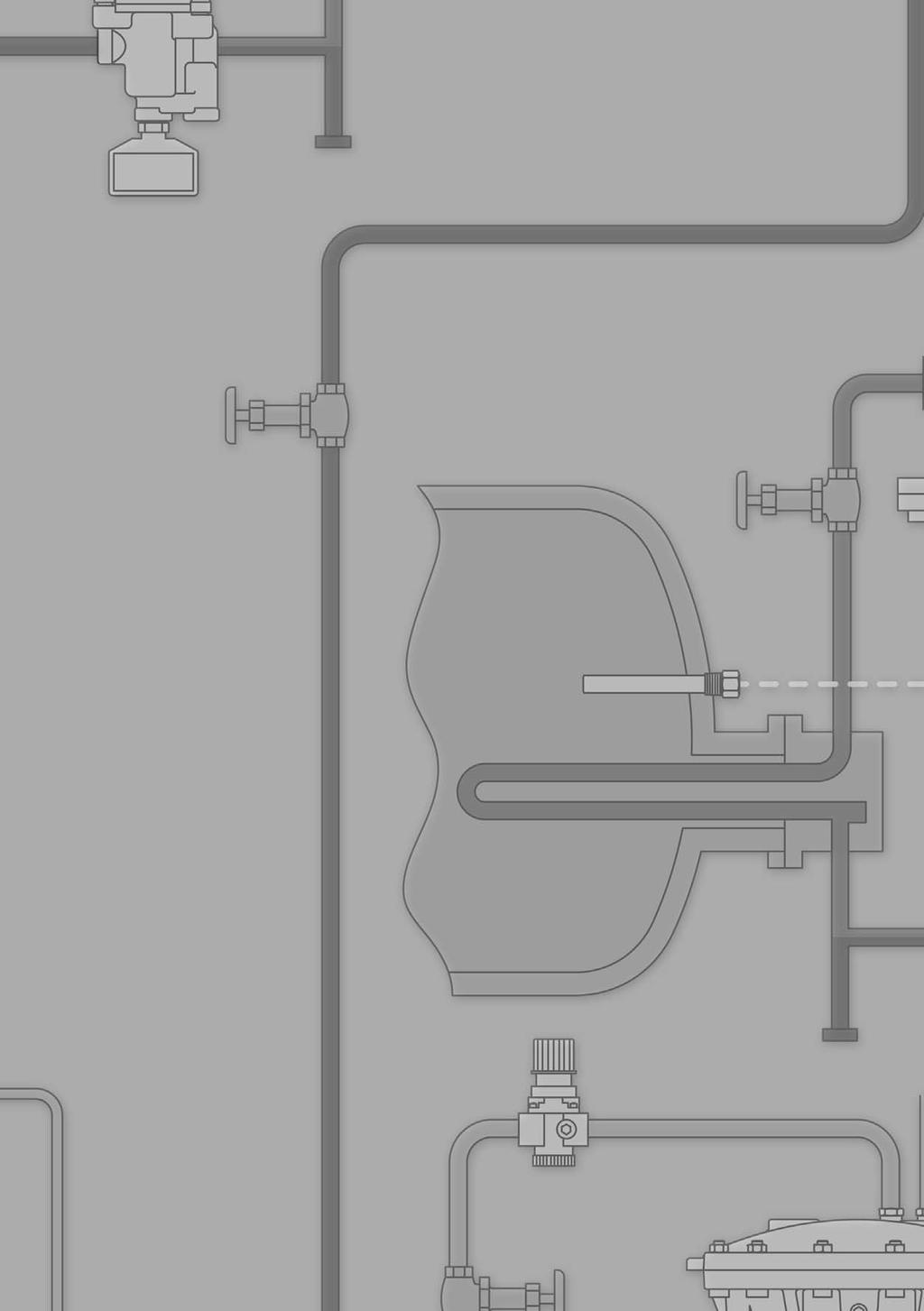
286

287 Steam Traps

288 Armstrong Steam Traps Steam Traps Pay ess money for energy and more attention to the environment. It s pretty obvious, reay. An efficient steam trap wastes ess energy, which means you burn ess fue and reduce emissions. The resuts are energy savings and a ceaner, heathier environment. By heping companies manage energy, Armstrong steam traps are aso heping protect the word we a share. As a steam trap wears, it oses efficiency and begins to waste energy. But Armstrong inverted bucket traps ast years onger than other traps. They operate more efficienty onger because the inverted bucket is the most reiabe steam trap operating principe known. Ceary, the onger an efficient trap asts, the more it reduces energy wasted, fue burned and poutants reeased into the air. It s an a-around positive situation that ets the environment win, too. Bringing energy down to earth in your faciity coud begin with a renewed focus on your steam system, especiay your steam traps. Said another way: Zeroing in your steam traps is an easy way to pay ess money for energy and more attention to the environment. Companies around the word are beginning to reaize that rather than being separate chaenges, energy and the environment are and have aways been a singe mission. And that quaity management in one area wi surey impact the other. ST-66
289 Steam Trap ID Charts Tabe ST Armstrong Steam Traps Iustration Type Series 200 Inverted Bucket Capacities to kg/h Series 800 Inverted Bucket w/strainer Capacities to kg/h Series 880 Inverted Bucket Capacities to kg/h TVS-800 Trap Vave Station Capacities to kg/h Series 980 Inverted Bucket Capacities to kg/h Mode EM Inverted Bucket Capacities to 480 kg/h Series 300 Inverted Bucket Capacities to kg/h Mode 411G Inverted Bucket Capacities to 590 kg/h Mode 421 Inverted Bucket Capacities to 590 kg/h Series 400 Inverted Bucket Capacities to kg/h Fow Direction Connection Type Screwed Fanged Screwed Fanged Screwed Fanged Screwed Fanged Screwed Socketwed Fanged Screwed Socketwed Fanged Screwed Socketwed Fanged Screwed Socketwed Fanged Screwed Socketwed Fanged Screwed Socketwed Fanged Max. Aow. Press. barg ««See tabes on pages ST-92, ST-94 and ST-96 for compete temperature/pressure rating information. Operating pressure and temperature may be imited depending on the cass of fange seected. TMA C Body Materia ASTM A48 Cass 30 Cast Iron ASTM A48 Cass 30 Cast Iron ASTM A48 Cass 30 Cast Iron ASTM A48 Cass 30 Cast Iron ASTM A216 WCB Carbon Stee Mode TVS-811 TVS-812 TVS Max. Oper. Press. barg Connection Size 1/2" 3/4" 1" 1 1/4" 1 1/2" 2" 2 1/2" Located on Page ST-76 ST-78 ST-82 ST-84 ST C 22.8 EM 32 ST-90 «« ««69 ««69 «« ««371 ««371 ««371 ««427 ASTM A105 Forged Stee ASTM A105 Forged Stee Body ASTM A105 Forged Stee Cap ASTM A216 WCB ASTM A182 F22 Forged Stee ,5 41, ST G 69 ST ST ST-96 Steam Traps ST-67
290 Steam Trap ID Charts Steam Traps Tabe ST Armstrong Steam Traps Iustration Type Mode 401-SH Inverted Bucket Capacities to 350 kg/h Mode 501-SH Inverted Bucket Capacities to 430 kg/h Fow Direction Connection Type Screwed Socketwed Fanged Screwed Socketwed Fanged Max. Aow. Press. barg TMA C Body Materia Carbon Stee ASTM A106 Gr. B 316L Stainess Stee ASTM A312 Mode Max. Oper. Press. barg Connection Size 3/8" 1/2" 3/4" 1" 1 1/4" 1 1/2" 2" Located on Page 401-SH 69 ST SH 106 ST-98 Series 5000 Inverted Bucket Capacities to kg/h Socketwed Fanged ««146 ««174 ««427 ASTM A182 F22 Forged Stee 5133G G 124 ST-100 Series 6000 Inverted Bucket Capacities to kg/h Socketwed Fanged ««241 ««454 ASTM A182 F22 Forged Stee 6155G 186 ST-102 Series 1000 Inverted Bucket Capacities to kg/h Series 1800 Inverted Bucket Capacities to kg/h Series 2000 Inverted Bucket Capacities to 590 kg/h TVS-4000 Trap Vave Station Screwed Socketwed Fanged Screwed Socketwed Fanged Screwed Socketwed Fanged Screwed Socketwed Fanged L Stainess Stee , L Stainess Stee L Stainess Stee ASTM A351 Gr. CF8M TVS ST-106 ST-108 ST ST-112 TVS-5000 Trap Vave Station Screwed Socketwed Fanged ASTM A350 LF2 TVS ST-116 Series 20-DC Automatic Differentia Controers Capacities to kg/h Screwed Fanged ASTM A48 Cass 30 Cast Iron 21-DC 22-DC 23-DC 24-DC 25-DC 26-DC ST-118 ««See tabes on pages ST-100 and ST-102 for compete temperature/pressure rating information. Operating pressure and temperature may be imited depending on the cass of fange seected. ST-68
291 Steam Trap ID Charts Tabe ST Armstrong Steam Traps Iustration Type Series 80-DC Automatic Differentia Controers Capacities to kg/h Series B & BI Foat & Thermostatic Capacities to kg/h Series A & AI Foat & Thermostatic Capacities to kg/h AIC DN15-25 Foat & Thermostatic Capacities to 900 kg/h AIC DN40-50 Foat & Thermostatic Capacities to kg/h Series JD & KD Foat & Thermostatic Capacities to kg/h Series L & M Foat & Thermostatic Capacities to kg/h ICS Foat & Thermostatic Capacities to kg/h Series CS Foat & Thermostatic Capacities to kg/h Series LS & MS Foat & Thermostatic Capacities to kg/h Fow Direction Connection Type Screwed Fanged Screwed Max. Aow. TMA Press. C barg , Screwed Screwed Fanged Screwed Fanged Screwed Fanged Screwed Fanged Fanged Screwed Socketwed Fanged Screwed Socketwed Fanged Body Materia ASTM A48 Cass 30 Cast Iron ASTM A48 Cass 30 Cast Iron ASTM A48 Cass 30 Cast Iron EN-GJS (EN1563) EN-GJS (EN1563) ASTM A395 Ductie Iron ASTM A48 Cass 30 Cast Iron ASTM A352 Gr. LCB Cast Stee ASTM A216 WCB Carbon Stee Mode 81-DC 82-DC 83-DC 84-DC 85-DC 86-DC B-2, BI-2 B-3, BI-3 B-4, BI-4 B-5 B-6 B-8 AI-2 A-3, AI-3 A-4, AI-4 A-5 A-6 A-8 15-AIC 30-AIC 75-AIC 125-AIC 200-AIC 100-AIC 200-AIC 300-AIC 465HP-AIC 15-JD 20-JD 30-JD 75-JD 125-JD 175-JD 250-JD 300-JD 30-KD 50-KD 300-KD L-8 L-10 M-12 ICS-2 ICS-3 ICS-4 ICS-6 ICS-8 CS-2 CS-3 CS-4 CS-5 CS-6 CS-8 s Series AI and BI for in-ine connection. Operating pressure and temperature may be imited depending on the cass of fange seected. LS-8 LS-10 MS-12 Max. Oper. Press. barg , , , , Connection Size 1/2" 3/4" 1" 1 1/4" 1 1/2" 2" 2 1/2" 3" s s s s s s Located on Page ST-120 ST-124 ST-126 ST-128 ST-130 ST-132 ST-130 ST-136 ST-138 ST-140 Steam Traps ST-69
292 Steam Trap ID Charts Tabe ST Armstrong Steam Traps Iustration Type Fow Direction Connection Type Max. Aow. TMA Press. C barg Body Materia Mode Max. Oper. Press. barg Connection Size 1/2" 3/4" 1" 1 1/4" 1 1/2" 2" 2 1/2" 3" Located on Page Steam Traps Mode F&T-2000 Foat & Thermostatic Capacities to 490 kg/h Screwed Socketwed Fanged L Stainess Stee F&T ST-142 Series FT-4000 Capacities to 660 kg/h Screwed Socketwed ASTM A240 Grade 304L FT-4075 FT-4150 FT-4225 FT-4300 FT ST-144 Tabe ST Armstrong Steam Traps Iustration Type Series CD-33 Controed Disc Capacities to kg/h Series CD-33S Controed Disc w/integra Strainer Capacities to kg/h Mode CD-3300 Controed Disc Capacities to 360 kg/h Fow Direction Connection Type Screwed Fanged Screwed Socketwed Fanged Max. Aow. Press. barg TMA C Body Materia ASTM A743 Gr. CA40 Stainess Stee Mode CD-33 CD-33L CD-33S CD-33SL Max. Oper. Press. barg 41 Connection Size 3/8" 1/2" 3/4" 1" Located on Page ST-150 ST-150 CD ST-151 CD-72S Controed Disc Capacities to 816 kg/h Screwed Socketwed Fanged ASTM A105N/A350 LF2 CI.1 CD-72S 41 ST-152 Series CD-40 Controed Disc Capacities to kg/h Screwed Carbon Stee CD-41 CD-42 CD ST-153 Series CD-60 Controed Disc Capacities to kg/h Screwed Socketwed Fanged Forged Carbon Stee CD-61 CD-62 CD ST-153 Mode SH-300 Bimetaic Capacities to kg/h Screwed Socketwed Fanged Carbon Stee SH ST-154 Mode AB-3000 Bimetaic Capacities to kg/h Screwed Socketwed Fanged L Stainess Stee AB ST-155 Mode AB-600 Bimetaic Capacities to kg/h Screwed Socketwed Fanged C 22.8 AB ST-156 Operating pressure and temperature may be imited depending on the cass of fange seected. * L = Low Pressure; H = High Pressure ST-70
293 Steam Trap ID Charts Tabe ST Armstrong Steam Traps Iustration Type Fow Mode SH-900 Bimetaic Capacities to kg/h Mode SH-1500 Bimetaic Capacities to kg/h Series WT Thermostatic Wafer Cod Water Startup Capacities to 730 kg/h Series WHT Thermostatic Wafer Cod Water Startup Capacities to 450 kg/h TC-300 Thermostatic Cod Water Startup Capacities to 454 kg/h Series TS Thermostatic Beows Capacities to 730 kg/h Series TT Thermostatic Beows Capacities to kg/h Mode TC-C Thermostatic Cean Steam Camp Capacities to kg/h Mode TC-S Thermostatic Cean Steam Seaed Capacities to kg/h Mode TC-R Thermostatic Cean Steam Boted Capacities to kg/h Direction Type Screwed Socketwed Fanged Screwed Socketwed Fanged Max. Aow. Press. barg TMA C Screwed Screwed Socketwed Screwed Socketwed Fanged Screwed Screwed Socketwed Fanged Threaded Screwed Screwed Socketwed Screwed Socketwed Fanged Sanitary End Body Materia ASTM A351 Gr.CF8M ASTM 217 Cer. C12A 304-L Stainess Stee C1018 Carbon Stee 304-L Stainess Stee 304-L Stainess Stee Mode SH-900 Max. Oper. Press. barg L = 44* H = 62* Connection Size 3/8" 1/2" 3/4" 1" Located on Page ST-157 SH ST-158 WT-1 28 WT-3 41 WT WMT /4" 3/8" ST-160 ST ASTM-A-105 TC ST-163 3,5 149 TS-2 3,5 Bronze 4,5 157 TS-3 4, , L Stainess Stee Stainess Stee 316L TTF-1 TTF-1R 20 TT-2000 ST-164 ST-166 TC-C 7 ST-168 Sanitary End Threaded Stainess Stee 316L TC-S 8,3 Tube End Sanitary End Threaded 8,3 177 Stainess Stee 316L TC-R 7 Tube End Operating pressure and temperature may be imited depending on the cass of fange seected. A modes compy with the Pressure Equipment Directive PED 97/23/EC. For detais, see specific product page or Armstrong PED Certificate. ST-168 ST-168 Steam Traps ST-71

294 The Inverted Bucket Steam Trap Steam Traps Energy Efficient Because It s So Reiabe The inverted bucket is the most reiabe steam trap operating principe known. The heart of its simpe design is a unique everage system that mutipies the force provided by the bucket to open the vave against pressure. Since the bucket is open at the bottom, it resists damage from water hammer, and wear points are heaviy reinforced for ong ife. Wear and corrosion resistance Free-foating guided ever vave mechanism is frictioness, and a wear points are heaviy reinforced. A working parts are stainess stee. Vave and seat are stainess stee, individuay ground and apped together in matched sets. The inverted bucket has ony two moving parts the vave ever assemby and the bucket. That means no fixed points, no compicated inkages. Nothing to stick, bind or cog. Virtuay no steam oss Steam does not reach the water-seaed discharge vave. Continuous air and CO 2 venting Vent in top of bucket provides continuous automatic air and CO 2 venting with no cooing ag or threat of air binding. Steam passing through vent is ess than that required to compensate for radiation osses from the trap so it s not wasted. Purging action Snap opening of the vave creates a momentary pressure drop and turbuence in the unit drained. This breaks up fims of condensate and air and speeds their fow to the trap. Exceent operation against back pressure Since trap operation is governed by the difference in density of steam and water, back pressure in the return ine has no effect on the abiity of the trap to open for condensate and cose against steam. Dependabe operation Simpe, direct operation with nothing to stick, bind or cog. Ony two moving parts the vave ever and the bucket. Freedom from dirt probems Condensate fow under the bottom edge of the bucket keeps sediment and sudge in suspension unti it is discharged with the condensate. Vave orifice opens wide and coses tighty. No buidup of dirt or cose cearances to be affected by scae. Resistance to damage from water hammer Open bucket or foat wi not coapse as a resut of water hammer. ST-72

295 Inverted Bucket Steam Trap Conserves Energy Even in the Presence of Wear Armstrong inverted bucket steam traps open and cose based on the difference in density between condensate and steam the inverted bucket principe. They open and cose genty, minimizing wear. This simpe fact means that inverted buckets are subject to ess wear than some other types of traps. In fact, as an Armstrong inverted bucket trap wears, its tight sea actuay improves. The ba vave and seat of the Armstrong trap provide essentiay ine contact resuting in a tight sea because the entire cosing force is concentrated on one narrow seating ring. An Armstrong inverted bucket trap continues to operate efficienty with use. Gradua wear sighty increases the diameter of the seat and aters the shape and diameter of the ba vave. But, as this occurs, a tight sea is sti preserved the ba merey seats itsef deeper. Corrosion-Resistant Parts The stainess stee vave and seat of the Armstrong inverted bucket steam trap are individuay ground and apped together in matched sets. A other working parts are wear- and corrosion-resistant stainess stee. Armstrong IB Vave Seating/Ba Vave Venting of Air and CO 2 The Armstrong inverted bucket provides continuous automatic air and CO 2 venting with no cooing ag or threat of air binding. Operation Against Back Pressure The Armstrong inverted bucket has exceent performance against back pressure. It has no adverse effect on inverted bucket operation other than to reduce its capacity by the ow differentia. The bucket simpy requires ess force to pu the vave open and cyce the trap. Freedom From Dirt Probems Armstrong designed its inverted bucket to be virtuay free of dirt probems. The vave and seat are at the top of the trap, far away from the arger partices of dirt, which fa to the bottom. Here the up-and-down action of the bucket puverizes them. Since the vave of an inverted bucket is either fuy cosed or open, dirt partices pass freey. And the swift fow of condensate from under the bucket s edge creates a unique sef-scrubbing action that sweeps dirt out of the trap. IB Vave Wear Characteristics Steam Traps Line Contact Singe Seat Infinite Number of Center Lines and Seating Circumferences Armstrong IB ba vave continues to seat itsef deeper, providing a tight sea even in the presence of wear. A dimensions and weights are approximate. Use certified print for exact dimensions. Design and materias are subject to change without notice. ST-73

296 IB Steam Trap Summary Capacity Chart Pressure difference in bar between steam ine and return ine with trap vave cosed Note: Above capacity chart does not incude a modes avaiabe. Refer to specific page of trap required for capacities not covered above. 200, 800 and 880 Series 300 Series 400 Series 5000 Series Steam Traps Modes 216, 816, 316, 416 Modes 215, 815, 315, 415, 5155 Modes 214, 814, 314, 5133 Modes 213, 813, 883, 313, 983, 413 Modes 312 Modes 212, 812, 882 Modes 211, 811, 881, 310, 411, 421 Modes 800, 880 Pressure difference in bar between steam ine and return ine with trap vave cosed Note: Above capacity chart does not incude a modes avaiabe. Refer to specific page of trap required for capacities not covered above. ST-74

297 How to Use the IB Steam Trap Summary Capacity Chart How the Capacity Chart was made The Armstrong capacity chart shows continuous discharge capacities of Armstrong traps under actua operating conditions as determined by iteray hundreds of tests. In these tests condensate at the steam temperature corresponding to the test pressure was used. The choking effect of fash steam through the orifice, as we as the back pressure created by fash steam, were automaticay taken into account. Actua instaation hookups were used so that pipe friction in both inet and discharge ines aso were refected in the resuts. Trap capacity ratings based on cod water tests which produce no fash steam woud be much too high. Orifice tests aso are too high because they ignore pipe friction. Theoretica cacuations of trap capacities have never been conservative. You can rey on Armstrong capacity ratings because they show actua capacities of hot condensate. Heavy sawtooth curves show capacities for traps using maximum possibe diameter orifices for the pressures shown. Thin ine curves extending down to the eft of the heavy curves show the capacities of Armstrong traps at pressures beow their maximum ratings. For exampe: a mode 216 trap with 1/2" orifice good for a maximum working pressure of 8,5 bar wi have a continuous discharge capacity of a itte ess than kg/h at 2,8 bar. How to use the inverted bucket trap capacity chart To seect an inverted bucket steam trap using the Armstrong capacity chart, you must know the condensate oad, safety factor and pressure differentia. Remember, the objective is aways to seect a trap that can 1) operate at the maximum differentia pressure and 2) hande the capacity at the minimum differentia pressure. Consider the foowing typica probems: Exampe 1: Constant Pressure and Condensing Rate Given: Maximum pressure differentia: 5 bar Operating differentia: 4 bar Condensate oad: 133 kg/h times 3:1 safety factor or: 400 kg/h Enter chart at 4 bar and go up to 400 kg/h capacity. This is directy on the 5/32" orifice ine as shown in Chart ST The capacity of this 5/32" orifice at pressures ess than 2 bar is indicated by the thin ine. Foow the ine to the right to the vertica drop at 5 bar. This means this orifice wi operate to a maximum of 5 bar differentia - the other requirement for this appication. Foow the heavy ine back to the eft and note that it's attached to the arrow indicating that the 211, 811 or 881 traps (1811 and 1011 are other possibiities) with the 5/32" orifice wi yied this capacity. This is the trap to use. Exampe 2: Constant Pressure and Condensing Rate but with Possibe High Back Pressure Assume for exampe: Maximum pressure differentia: 6 bar Operating differentia minimum: 3 bar Operating differentia normay: 4 bar Condensate oad: 133 kg/h times 3:1 safety factor or: 400 kg/h To sove the probem, refer to the sawtooth chart, page ST-74. Enter at the minimum differentia pressure (3 bar) and move up unti you intersect a ine that is above 400 kg/h capacity, which is the first thin ine above the heavy sawtooth for the 211, 811 and 881 traps. Note that this is the continuation of the capacity ine for the 5/32" orifice for the 212, 812 and 882 traps. Now foow the ine to the right unti the vertica drop at 8,5 bar differentia. This is within our requirement of 6 bar. Therefore a 5/32" orifice can hande the 400 kg/h condensate oad when fitted into a 212, 812 or 882 trap and that it wi not ock shut at the 6 bar maximum differentia. This is the trap to use since it wi hande the oad at both the minimum and maximum operating differentias, even though it has a maximum operating pressure differentia of 8,5 bar. Orifice sizes: 1 7/8" = 47,0 mm 5/16" = 7,9 mm 1 5/8" = 41,0 mm 19/64" = 7,5 mm 1 17/32" = 39,0 mm 9/32" = 7,1 mm 1 1/8" = 28,0 mm 17/64" = 6,7 mm 1 1/16" = 27,0 mm 1/4" = 6,4 mm 7/8" = 22,2 mm 7/32" = 5,6 mm 3/4" = 19,0 mm 13/64" = 5,1 mm 11/16" = 17,5 mm 3/16" = 4,8 mm 5/8" = 15,9 mm 11/64" = 4,4 mm 9/16" = 14,3 mm 5/32" = 4,0 mm 1/2" = 12,7 mm 1/8" = 3,2 mm 7/16" = 11,2 mm 7/64" = 2,8 mm 3/8" = 9,5 mm # 38 = 2,5 mm 11/32" = 8,7 mm 5/64" = 2,0 mm Chart ST-75-1: Seection Curve Exampe 1 Capacity in kg/h Modes 211, 811, 881 Pressure Differentia in bar Steam Traps ST-75
298 200 Series Inverted Bucket Steam Traps Cast Iron for Vertica Instaation For Pressures to 17 bar...capacities to kg/h A Steam Traps B BB Description The most reiabe steam trap known the inverted bucket provides efficient condensate drainage of virtuay a types of steam-using equipment. Put the inverted bucket to work in a tough cast iron package, and you have the best of both words. Because they operate efficienty for onger periods of time, Armstrong cast iron inverted buckets add soid energy savings to ower repacement/abor costs. A unique everage system mutipies the force provided by the bucket to open the vave against system pressure. The mechanism is free-foating, and has no fixed pivots to create wear or friction. Because the mechanism is ocated at the top of the trap, no dirt can coect on the orifice. Sma partices of dirt are hed in suspension unti discharged by the fu differentia purging action when the bucket sinks, puing the vave off the seat. The discharge orifice is surrounded by a water sea, preventing ive steam oss. Automatic air venting is provided by a sma vent hoe in the bucket, which provides continuous automatic air and CO 2 venting at steam temperature. Inverted bucket traps drain continuousy, athough discharging intermittenty, aowing no condensate backup. They are aso resistant to water hammer. Maximum Operating Conditions Maximum aowabe pressure (vesse design) : C Maximum operating pressure: 17 bar Maximum back pressure: 99% of inet pressure Connections Screwed BSPT and NPT Fanged DIN or ANSI (screw on) Materias Body: ASTM A48 Cass 30 Cap: ASTM A48 Cass 30 ASTM A-105 (Ony 215 if PMA > 9 bar) Internas: A stainess stee 304 Vave and seat: Stainess Stee 17-4PH Test pug: Carbon stee Options Stainess stee interna check vave Thermic vent bucket Scrub wire Specification Inverted bucket steam trap, type... in cast iron, with continuous air venting at steam temperature, free foating stainess stee mechanism, and discharge orifice at the top of the trap. Maximum aowabe back pressure 99% of inet pressure. How to Order Specify: Mode number Size and type of pipe connection Maximum working pressure that wi be encountered or orifice size Any options required Tabe ST Series, Bottom Inet, Top Outet Trap (dimensions in mm) Add suffix CV to mode number for interna check vave, T for thermic vent bucket. Mode No Pipe Connections Test pug 1/8" 3/8" 1/2" 1/2" 3/4" 1" A Fange Diameter B Face-to-Face (screwed) BB Face-to-Face (fanged PN40*) B Face-to-Face (screwed) for PMA > 9 bar N/A N/A N/A N/A 327 N/A BB Face-to-Face (fanged PN40*) for PMA > 9 bar N/A N/A N/A N/A N/A Number of Bots Weight in kg (screwed) 2,7 5,2 9,2 15,0 20,3 35,2 Weight in kg (fanged PN40*) 4,1 7,0 7, , ,6 20, , ,6 41,2 * Other fange sizes, ratings and face-to-face dimensions are avaiabe on request. Shade indicates products that are CE Marked according to the PED (97/23/EC). A the other modes compy with the Artice 3.3 of the same directive. May be derated depending on fange rating and type. A dimensions and weights are approximate. Use certified print for exact dimensions. Design and materias are subject to change without notice. ST-76
299 200 Series Inverted Bucket Steam Traps Cast Iron for Vertica Instaation For Pressures to 17 bar...capacities to kg/h Tabe ST Mode 211 Capacity Tabe ST Mode 212 Capacity , , Capacity, kg/h Capacity, kg/h Steam Traps Pressure, bar Pressure, bar Tabe ST Mode 213 Capacity Tabe ST Mode 214 Capacity ,5 8,5 12, ,5 8,5 12,5 17 Capacity, kg/h Capacity, kg/h Pressure, bar Pressure, bar Tabe ST Mode 215 Capacity Tabe ST Mode 216 Capacity ,5 15,5 1 1, ,5 8,5 12, Capacity, kg/h Capacity, kg/h Pressure, bar Pressure, bar A dimensions and weights are approximate. Use certified print for exact dimensions. Design and materias are subject to change without notice. ST-77
300 Series Inverted Bucket Steam Traps Cast Iron for Horizonta Instaation For Pressures to 17 bar...capacities to kg/h Steam Traps Description The most reiabe steam trap known the inverted bucket provides efficient condensate drainage of virtuay a types of steam-using equipment. Put the inverted bucket to work in a tough cast iron package, and you have the best of both words. Because they operate efficienty for onger periods of time, Armstrong cast iron inverted buckets add soid energy savings to ower repacement/abor costs. A Armstrong cast iron inverted bucket steam traps are repairabe for even bigger maintenance savings. A unique everage system mutipies the force provided by the bucket to open the vave against system pressure. The mechanism is free-foating, and has no fixed pivots to create wear or friction. Because the mechanism is ocated at the top of the trap, no dirt can coect on the orifice. Sma partices of dirt are hed in suspension unti discharged by the fu differentia purging action when the bucket sinks, puing the vave off the seat. The discharge orifice is surrounded by a water sea, preventing ive steam oss. Automatic air venting is provided by a sma vent hoe in the bucket, which provides continuous automatic air and CO 2 venting at steam temperature. Inverted bucket traps drain continuousy, athough discharging intermittenty, aowing no condensate backup. They are aso resistant to water hammer. Maximum Operating Conditions Maximum aowabe pressure (vesse design) : C Maximum operating pressure: Mode 800: 10 bar Mode : 17 bar Maximum back pressure: 99% of inet pressure Connections Screwed BSPT and NPT Fanged DIN or ANSI (screw on) Materias Body: ASTM A48 Cass 30 Internas: A stainess stee 304 Vave and seat: Stainess Stee 17-4PH Test pug: Carbon stee Options Stainess stee interna check vave Thermic vent bucket Stainess stee pop drain Probe connection Thermo drain Scrub wire Specification Inverted bucket steam trap, type... in cast iron, with continuous air venting at steam temperature, free-foating stainess stee mechanism, and discharge orifice at the top of the trap. Maximum aowabe back pressure 99% of inet pressure. How to Order Specify: Mode number Size and type of pipe connection Maximum working pressure that wi be encountered or orifice size Any options required Tabe ST Series Side Inet, Side Outet Trap (dimensions in mm) Add suffix CV to mode number for interna check vave, T for thermic vent bucket. Mode No. 800* Pipe Connections Test pug 1/4" 1/4" 1/2" 3/4" B Height C Face-to-Face (screwed) CC Face-to-Face (fanged PN40**) D Bottom to C L Inet Number of Bots 6 Weight in kg (screwed) 2,3 2,7 6,8 12,5 Weight in kg (fanged PN40**) 3,6 4,3 4,1 4,3 4,8 8,2 9,0 14,3 14,8 * Cannot be furnished with both thermic vent bucket and check vave. ** Other fange sizes, ratings and face-to-face dimensions are avaiabe on request. A modes compy with the artice 3.3 of the PED (97/23/EC). May be derated depending on fange rating and type. A dimensions and weights are approximate. Use certified print for exact dimensions. Design and materias are subject to change without notice. ST-78
301 Series Inverted Bucket Steam Traps Cast Iron for Horizonta Instaation For Pressures to 17 bar...capacities to kg/h Tabe ST Mode 800 Capacity Tabe ST Mode 811 Capacity 1,4 5,5 8,5 10, , Capacity, kg/h Capacity, kg/h Steam Traps Pressure, bar Pressure, bar Tabe ST Mode 812 Capacity Tabe ST Mode 813 Capacity , ,5 8,5 12, Capacity, kg/h Capacity, kg/h Pressure, bar Pressure, bar A dimensions and weights are approximate. Use certified print for exact dimensions. Design and materias are subject to change without notice. ST-79
302 Series Inverted Bucket Steam Traps Cast Iron for Horizonta Instaation For Pressures to 17 bar...capacities to kg/h CC C Steam Traps D B Description The most reiabe steam trap known the inverted bucket provides efficient condensate drainage of virtuay a types of steam-using equipment. Put the inverted bucket to work in a tough cast iron package, and you have the best of both words. Because they operate efficienty for onger periods of time, Armstrong cast iron inverted buckets add soid energy savings to ower repacement/abor costs. A Armstrong cast iron inverted bucket steam traps are repairabe for even bigger maintenance savings. A unique everage system mutipies the force provided by the bucket to open the vave against system pressure. The mechanism is free-foating, and has no fixed pivots to create wear or friction. Because the mechanism is ocated at the top of the trap, no dirt can coect on the orifice. Sma partices of dirt are hed in suspension unti discharged by the fu differentia purging action when the bucket sinks, puing the vave off the seat. The discharge orifice is surrounded by a water sea, preventing ive steam oss. Automatic air venting is provided by a sma vent hoe in the bucket, which provides continuous automatic air and CO 2 venting at steam temperature. Inverted bucket traps drain continuousy, athough discharging intermittenty, aowing no condensate backup. They are aso resistant to water hammer. Maximum Operating Conditions Maximum aowabe pressure (vesse design) : C Maximum operating pressure: 17 bar Maximum back pressure: 99% of inet pressure Connections Screwed BSPT and NPT Fanged DIN or ANSI (screw on) Materias Body: ASTM A48 Cass 30 Internas: A stainess stee 304 Vave and seat: Stainess Stee 17-4PH Test pug: Carbon stee Options Stainess stee interna check vave Thermic vent bucket Stainess stee pop drain Probe connection Thermo drain Scrub wire Specification Inverted bucket steam trap, type... in cast iron, with continuous air venting at steam temperature, free-foating stainess stee mechanism, and discharge orifice at the top of the trap. Maximum aowabe back pressure 99% of inet pressure. How to Order Specify: Mode number Size and type of pipe connection Maximum working pressure that wi be encountered or orifice size Any options required Tabe ST Series Side Inet, Side Outet Trap (dimensions in mm) Add suffix CV to mode number for interna check vave, T for thermic vent bucket. Mode No Pipe Connections Test pug 1" 1 1/2" 2" B Height C Face-to-Face (screwed) CC Face-to-Face (fanged PN40*) D Bottom to C L Inet Number of Bots 8 Weight in kg (screwed) 20,0 32,2 59,4 Weight in kg (fanged PN40*) 23,0 24,6 34,6 36,2 36,6 38,2 65,4 68,2 * Other fange sizes, ratings and face-to-face dimensions are avaiabe on request. A modes are CE Marked according to the PED (97/23/EC), but PMA for 816 is 15 bar. May be derated depending on fange rating and type. A dimensions and weights are approximate. Use certified print for exact dimensions. Design and materias are subject to change without notice. ST-80
303 Series Inverted Bucket Steam Traps Cast Iron for Horizonta Instaation For Pressures to 17 bar...capacities to kg/h Tabe ST Mode 814 Capacity Tabe ST Mode 815 Capacity Capacity, kg/h ,5 8,5 12,5 17 Capacity, kg/h ,5 15,5 17 Steam Traps Pressure, bar Pressure, bar Tabe ST Mode 816 Capacity 1 1, ,5 8,5 12,5 17 Capacity, kg/h Pressure, bar A dimensions and weights are approximate. Use certified print for exact dimensions. Design and materias are subject to change without notice. ST-81
304 880 Series Inverted Bucket Steam Traps Cast Iron for Horizonta Instaation, with Integra Strainer For Pressures to 17 bar...capacities to kg/h CC C Steam Traps D B E Description The most reiabe steam trap known he inverted bucket provides efficient condensate drainage of virtuay a types of steam-using equipment. Put the inverted bucket to work in a tough cast iron package with an integra strainer, and you have the best of both words. Because they operate efficienty for onger periods of time, Armstrong cast iron inverted buckets add soid energy savings to ower repacement/abor costs. A Armstrong cast iron inverted bucket steam traps are repairabe for even bigger maintenance savings. A unique everage system mutipies the force provided by the bucket to open the vave against system pressure. The mechanism is free-foating, and has no fixed pivots to create wear or friction. Because the mechanism is ocated at the top of the trap, no dirt can coect on the orifice. Sma partices of dirt are hed in suspension unti discharged by the fu differentia purging action when the bucket sinks, puing the vave off the seat. The discharge orifice is surrounded by a water sea, preventing ive steam oss. Automatic air venting is provided by a sma vent hoe in the bucket, which provides continuous automatic air and CO 2 venting at steam temperature. Inverted bucket traps drain continuousy, athough discharging intermittenty, aowing no condensate backup. They are aso resistant to water hammer. Connections Screwed BSPT and NPT Fanged DIN or ANSI (screw on, except for mode 881F integra) Maximum Operating Conditions Maximum aowabe pressure (vesse design) : C Maximum operating pressure: Maximum back pressure: 881F: C (PN16) Mode 880: 10 bar Mode : 17 bar 99% of inet pressure Materias Body: ASTM A48 Cass 30 Internas: A stainess stee 304 Vave and seat: Stainess Stee 17-4PH Test pug: Carbon stee Strainer: Stainess stee 304 Options Stainess stee interna check vave Thermic vent bucket Scrub wire Specification Inverted bucket steam trap, type... in cast iron with integra strainer, with continuous air venting at steam temperature, with free-foating stainess stee mechanism, and discharge orifice at the top of the trap. Maximum aowabe back pressure 99% of inet pressure. How to Order Specify: Mode number Size and type of pipe connection Maximum working pressure that wi be encountered or orifice size Any options required Tabe ST Series Side Inet, Side Outet Trap with Integra Strainer (dimensions in mm) Add suffix CV to mode number for interna check vave, T for thermic vent bucket. Mode No. 880* F Pipe Connections Test pug 1/4" 1/4" 1/2" 3/4" B Height C Face-to-Face (screwed) CC Face-to-Face (fanged PN40** - 881F PN16) D Bottom to C L Inet E Bowdown Connection (883 ony) N/A N/A 3/8" 1/2" Number of Bots 6 Weight in kg (screwed) 2,5 2,7 7 14,1 Weight in kg (fanged PN40** - 881F PN16) 4,0 4,6 3,8 4,2 4,6 8,8 9,4 15,6 16,1 17,7 * Cannot be furnished with both thermic vent bucket and check vave. ** Other fange sizes, ratings and face-to-face dimensions are avaiabe on request. A modes compy with the artice 3.3 of the PED (97/23/EC). May be derated depending on fange rating and type. A dimensions and weights are approximate. Use certified print for exact dimensions. Design and materias are subject to change without notice. ST-82
305 880 Series Inverted Bucket Steam Traps Cast Iron for Horizonta Instaation, with Integra Strainer For Pressures to 17 bar...capacities to kg/h Tabe ST Mode 880 Capacity Tabe ST Mode 881 Capacity 1,4 5,5 8,5 10, , Capacity, kg/h Capacity, kg/h Steam Traps Pressure, bar Pressure, bar Tabe ST Mode 882 Capacity Tabe ST Mode 883 Capacity , ,5 8,5 12, Capacity, kg/h Capacity, kg/h Pressure, bar Pressure, bar A dimensions and weights are approximate. Use certified print for exact dimensions. Design and materias are subject to change without notice. ST-83

306 TVS-800 Series Cast Iron Trap Vave Station Put the principe of the inverted bucket to work in a tough cast iron package and you have the best of both words energy efficiency and ong-asting reiabiity. Add the advantages of vaves integrated into one compact trap/vave casting, and you extend the benefits into instaation, trap testing and maintenance. A the components are concentrated in a singe, accessibe package and can be deat with in-ine. And if you have existing Armstrong cast iron traps in-ine, identica face-to-face dimensions wi make retrofitting with a new, patented* Armstrong Trap Vave Station (TVS) a snap. You aso reduce your inventory requirements. So you eiminate what you re paying just to keep parts on hand. Steam Traps Integra isoation vaves Rugged cast iron package Reduced costs TVS saves on these fronts: energy, instaation and maintenance. Integration of trap and vaves Inverted bucket ong ife and energy efficiency, pus the savings and convenience of components merged into one space-saving package. A fu range of options TVS wi accommodate a test vave, strainer, interna check vave, thermic vent bucket, TrapAert and SteamEye remote steam trap monitoring system for steam traps. Easy, in-ine repairabiity Eimination of potentia eak points Reduced design time Permits combining products with exact face-to-face dimensions. Energy-efficient inverted bucket steam trap Optiona integra strainer *U.S. Patent ST-84

307 TVS-800 Series Cast Iron Trap Vave Station TVS makes a ong story short. Typica Instaation Trap Vave Station Steam Traps Inverted bucket trap with two isoation vaves Inverted bucket trap with two isoation vaves, strainer Inverted bucket trap with two isoation vaves, strainer and check vave The Innovation Is Integration The Armstrong TVS makes what used to be ong, compicated steam instaation stories simpe and compact. It shortens instaations by integrating components specificay an inverted bucket steam trap with two or more vaves. For exampe, here s an od description for a typica instaation: vave-nippe-strainer-nippe-trap-nippe-vave. It s a ong tae, even for this simpe piping arrangement. The Trap Vave Station rewrites this steam story: pipe-tvs-pipe. In other words, the TVS makes it a one, deivering the functions of mutipe components in a dramaticay smaer unit. It integrates two high-vaue products in a package of revoutionary versatiity. Look above to see how the Armstrong cast iron Trap Vave Station has rewritten these typica steam instaations. Average Service Life for Different Trap Types 14 bar Steam Pressure Thermodynamic disc Foat and thermostatic Inverted bucket Baanced pressure thermostatic Bimetaic thermostatic Above data from ICI Engineer January 1993 specia issue with permission from ICI Engineering. ST-85
308 TVS-800 Series Trap Vave Stations Cast Iron for Horizonta Instaation, with Integra Piston Vaves For Pressures to 17 bar...capacities to kg/h CC CC Steam Traps D B D B Mode TVS-811 Series TVS-812/813 Series TVS-811/812/813 - Top View Same principe. Different package. Now the energy-saving performance and reiabiity of the inverted bucket steam trap are avaiabe in a versatie new package. You sti enjoy a the famiiar benefits. And the same efficient condensate drainage from virtuay every kind of steam-using equipment. But what you find new are a the benefits of a piston vave integrated into the same space-saving package. Maximum Operating Conditions Maximum aowabe pressure (vesse design) : C Maximum operating pressure: 17 bar Maximum back pressure: 99% of inet pressure Connections Screwed BSPT and NPT Fanged DIN or ANSI (screw on) Materias Cap and Body: ASTM A48 Cass 30 Internas: A stainess stee 304 Vave and seat: Stainess Stee 17-4PH Piston Vave Hande : Cast Iron ASTM A47 Internas: Stainess Stee Vave Seaing Rings: Graphite and Stainess Stee Bowdown vave: Stainess Stee Options Stainess stee interna check vave Thermic vent bucket Stainess stee pop drain Integra strainer Scrub wire Probe connection Bowdown vave (TVS-811 and TVS-812 ony) Specification Inverted bucket steam trap, type... in cast iron, with continuous air venting at steam temperature, free-foating stainess stee mechanism, and discharge orifice at the top of the trap. Integra upstream and downstream shutoff piston stye vaves in same dimensiona space as standard bucket trap. Maximum aowabe back pressure 99% of inet pressure. How to Order Specify: Mode number Size and type of pipe connection Maximum working pressure that wi be encountered or orifice size Any options required Tabe ST TVS-800 Series Trap Vave Station (dimensions in mm) Mode No. TVS-811 TVS-812 TVS-813 Pipe Connections Test Pug 1/4" 1/2" 3/4" A Width Across Handwhees B Height Vave Open C Face-to-Face (screwed) CC Face-to-Face (fanged PN40*) D Bottom to C L Inet E Width F Number of Bots Weight in kg (screwed) 5,4 11,3 24,0 Weight in kg (fanged PN40*) 6,8 7,0 12,7 13,5 25,8 26,3 * Other fange sizes, ratings and face-to-face dimensions are avaiabe on request. A modes compy with the artice 3.3 of the PED (97/23/EC). May be derated depending on fange rating and type. A dimensions and weights are approximate. Use certified print for exact dimensions. Design and materias are subject to change without notice. ST-86
309 TVS-800 Series Trap Vave Stations Cast Iron for Horizonta Instaation, with Integra Piston Vaves For Pressures to 17 bar...capacities to kg/h Tabe ST Mode TVS-811 Capacity Tabe ST Mode TVS-812 Capacity , , Capacity, kg/h Steam Traps Pressure, bar Pressure, bar Tabe ST Mode TVS-813 Capacity ,5 8,5 12,5 17 Pressure, bar Options Interna Check Vaves are spring-oaded stainess stee and screw directy into the trap inet or into an extended inet tube having a pipe couping at the top to save fittings, abor and money. Thermic Vent Buckets have a bimeta controed auxiiary air vent for discharging arge amounts of air on start-up. Integra Strainer is made from 20 x 20 stainess stee screen. Probe Connections are avaiabe for trap monitoring. Bowdown Vave for cearing strainer of dirt and debris. Integra Strainer Thermic Air Vent in Bucket Interna Check Vave A dimensions and weights are approximate. Use certified print for exact dimensions. Design and materias are subject to change without notice. ST-87
310 980 Series Inverted Bucket Steam Traps Cast Stee for Horizonta Instaation, with Integra Strainer For Pressures to 41 bar...capacities to kg/h Steam Traps Description Armstrong offers two sizes of cast stee traps with in-ine horizonta pipe connections and integra strainers with a choice of screwed, socketwed or fanged connections. A unique everage system mutipies the force provided by the bucket to open the vave against system pressure. The mechanism is free-foating, and has no fixed pivots to create wear or friction. Because the mechanism is ocated at the top of the trap, no dirt can coect on the orifice. Sma partices of dirt are hed in suspension unti discharged by the fu differentia purging action when the bucket sinks, puing the vave off the seat. The discharge orifice is surrounded by a water sea, preventing ive steam oss. Automatic air venting is provided by a sma vent hoe in the bucket, which provides continuous automatic air and CO 2 venting at steam temperature. Inverted bucket traps drain continuousy, athough discharging intermittenty, aowing no condensate backup. They are aso resistant to water hammer. Maximum Operating Conditions Maximum aowabe pressure (vesse design) : C Maximum operating pressure: 41 bar Maximum back pressure: 99% of inet pressure Materias Body: ASTM A216 WCB Internas: A stainess stee 304 Vave and seat: Stainess Stee 17-4PH (<35 bar) Titanium (>35 bar) Strainer: Stainess stee 304 Test pug: Carbon stee Options Stainess stee interna check vave Thermic vent bucket 17 bar maximum Scrub wire Specification Inverted bucket steam trap, type... in cast stee, with continuous air venting at steam temperature, free-foating stainess stee mechanism, integra strainer, and discharge orifice at the top of the trap. Maximum aowabe back pressure 99% of inet pressure. How to Order Specify: Mode number Size and type of pipe connection. When fanges are required, specify type of fange in detai Maximum working pressure that wi be encountered or orifice size Any options required Connections Screwed BSPT and NPT Socketwed Fanged DIN or ANSI (weded) Tabe ST Series Side Inet, Side Outet Trap with Integra Strainer (dimensions in mm) Mode No Pipe Connections Test pug 1/2" 3/4" A Fange Diameter B Height C Face-to-Face (screwed & SW) CC Face-to-Face (fanged PN40*) D Bottom to C L Inet E Bowdown Connection 3/8" 3/4" Weight in kg (screwed & SW) 5,2 19,5 Weight in kg (fanged PN40*) 7,0 26,0 * Other fange sizes, ratings and face-to-face dimensions are avaiabe on request. Shade indicates products that are CE Marked according to the PED (97/23/EC). A the other modes compy with the Artice 3.3 of the same directive. May be derated depending on fange rating and type. A dimensions and weights are approximate. Use certified print for exact dimensions. Design and materias are subject to change without notice. ST-88
311 980 Series Inverted Bucket Steam Traps Cast Stee for Horizonta Instaation, with Integra Strainer For Pressures to 41 bar...capacities to kg/h Tabe ST Mode 981 Capacity Tabe ST Mode 983 Capacity 1,4 3, , ,5 8,5 12, Capacity, kg/h Capacity, kg/h 41 Steam Traps Pressure, bar Pressure, bar A dimensions and weights are approximate. Use certified print for exact dimensions. Design and materias are subject to change without notice. ST-89

312 EM Inverted Bucket Steam Trap Forged Carbon Stee for Horizonta Instaation For Pressures to 32 bar Capacities to 480 kg/h CC C Steam Traps D B BB Description Armstrong's type EM forged stee inverted bucket steam trap combines the most reiabe steam trap operating principe known in a body, which can be opened for Easy Maintenance. High resistance to wear, corrosion and water hammer. The free-foating guided ever vave mechanism is frictioness with a wear points heaviy reinforced. A working parts are stainess stee; vave and seat are hardened chrome stee, individuay ground and apped. Freedom from dirt probems. Condensate fow under bottom edge of bucket keeps sediment and sudge in suspension unti discharged by fu differentia purging action. Vave orifice opens wide - coses tight. There is no buidup of dirt, no cose cearances to be affected by scae. Under norma conditions of reasonaby cean steam, a strainer is not necessary. However, this is eft to the user's discretion. Air handing abiity. Vent in bucket top provides continuous automatic air and CO 2 venting with no cooing eg and prevents air binding. Wigge wire ensures cean vent hoe at a times. Any steam passing through vent is condensed and discharged as iquid. No steam oss. Steam does not reach the water-seaed vave. Inverted bucket traps require no adjustment and no ive steam to operate. Maximum operating conditions Maximum aowabe pressure (vesse design) : 32 bar C Maximum operating pressure: 32 bar Maximum back pressure: 99% of inet pressure Materias Body: Forged carbon stee Internas: A stainess stee 304 Vave and seat: Stainess Stee 17-4PH Gasket: Spira wounded graphite Bots: 24 CrMo5 Options Bucket vent scrubbing wire for heavy dirt/oi conditions Probe connection (3/8") for use of TrapAert, the sef-diagnostic steam traps For superheated steam we advise steited vave and seat Specification Inverted bucket steam trap, type EM in forged stee, with automatic air vent, free-foating ever mechanism, with the orifice in the top. Maximum aowabe back pressure 99% of inet pressure. How to order Specify: Size and type of pipe connection Maximum working pressure that wi be encountered or orifice size Maximum condensate oad Any options required Connections Screwed BSPT and NPT Socketwed Fanged DIN or ANSI (weded) Tabe ST Mode EM Side Inet, Side Outet Trap (dimensions in mm) Pipe Connections C Face-to-Face (screwed & SW) CC Face-to-Face (fanged PN40*) D Bottom to C L Inet B Height (screwed & SW) BB Height (fanged PN40*) Weight in kg (screwed & SW) 3,1 3,1 Weight in kg (fanged PN40*) 5,5 7,1 8,1 * Other fange sizes, ratings and face-to-face dimensions are avaiabe on request. A sizes compy with the artice 3.3 of the PED (97/23/EC). May be derated depending on fange rating and type. A dimensions and weights are approximate. Use certified print for exact dimensions. Design and materias are subject to change without notice. ST-90
313 EM Inverted Bucket Steam Trap Forged Carbon Stee for Horizonta Instaation For Pressures to 32 bar Capacities to 480 kg/h Tabe ST Mode EM Capacity 1,5 3, , Capacity, kg/h 132 Steam Traps Pressure, bar A dimensions and weights are approximate. Use certified print for exact dimensions. Design and materias are subject to change without notice. ST-91
314 300 Series Inverted Bucket Steam Traps Forged Carbon Stee for Vertica Instaation For Pressures to 45 bar...capacities to kg/h Steam Traps Description Armstrong offers its 300 Series forged carbon stee traps for vertica instaation with a choice of screwed, socketwed or fanged connections. A unique everage system mutipies the force provided by the bucket to open the vave against system pressure. The mechanism is free-foating, and has no fixed pivots to create wear or friction. Because the mechanism is ocated at the top of the trap, no dirt can coect on the orifice. Sma partices of dirt are hed in suspension unti discharged by the fu differentia purging action when the bucket sinks, puing the vave off the seat. The discharge orifice is surrounded by a water sea, preventing ive steam oss. Automatic air venting is provided by a sma vent hoe in the bucket, which provides continuous automatic air and CO 2 venting at steam temperature. Inverted bucket traps drain continuousy, aowing no condensate backup. They are aso resistant to water hammer. Specification Inverted bucket steam trap, type... in forged carbon stee, with continuous air venting at steam temperature, free-foating stainess stee mechanism, and discharge orifice at the top of the trap. Maximum aowabe back pressure 99% of inet pressure. How to Order Specify: Mode number Size and type of pipe connection. When fanges are required, specify type of fange in detai Maximum working pressure that wi be encountered or orifice size Any options required A K A K For Superheat Service: 1. Don t oversize the orifice; a restricted orifice may be advisabe. 2. Specify a burnished vave and seat and an extended inet tube and check vave. 3. Provide a drip eg of adequate diameter and ength. 4. Provide a generous ength ( mm) of inet piping, with the trap beow the main. 5. Don t insuate the trap or the inet piping. B BB Connections Screwed BSPT and NPT Socketwed Fanged DIN or ANSI (weded) Materias Body: Internas: Vave and seat: ASTM A105 Modes 312, 313, 316 are aso avaiabe with cast 316 stainess stee bodies and astainess stee internas A stainess stee 304 (arger sizes have cast iron bucket weights) Stainess Stee 17-4PH (<35 bar) Titanium (>35 bar) Options Stainess stee interna check vave Thermic vent bucket 17 bar maximum Scrub wire G Mode 300 Trap bar bar , , ,5 34, , , Notes: Maximum operating pressure to be marked on namepate wi be determined by actua orifice used. Maximum aowabe pressures shown in bodface wi be marked on namepate, uness otherwise requested. Traps with fanges may have different pressure-temperature ratings. Maximum back pressure is 99% of inet pressure. G Series 300 FW Trap Tabe ST Pressure-Temperature Rating for Forged Stee Traps Mode No. Maximum Oper. Pr., Saturated Steam Maximum Aowabe Pressure (Vesse Design) of Pressure - Containing Parts at Indicated Temperature -28 C / +343 C 371 C 399 C 427 C Tabe ST Series Bottom Inet, Top Outet Trap (dimensions in mm) Add suffix CV to trap number for interna check vave. Mode No. Screwed or SW Mode No. Fanged FW FW FW FW FW FW Pipe Connections A Fange Diameter B Face-to-Face (screwed & SW) BB Face-to-Face (fanged PN100*) G Body Outside Diameter K C LOutet to C LInet 14,3 31,7 36,5 36,5 44,4 54,0 Number of Bots Weight in kg (screwed & SW) 4,5 13,6 22,0 31,8 44,5 81,2 Weight in kg (fanged PN100*) 5,5 6,5 14,5 15, ,5 23, ,5 37,0 45,5 47, ,8 87,8 * Other fange sizes, ratings and face-to-face dimensions are avaiabe on request. Shade indicates products that are CE Marked according to the PED (97/23/EC). A the other modes compy with the Artice 3.3 of the same directive. May be derated depending on fange rating and type. A dimensions and weights are approximate. Use certified print for exact dimensions. Design and materias are subject to change without notice. ST-92
315 300 Series Inverted Bucket Steam Traps Forged Carbon Stee for Vertica Instaation For Pressures to 45 bar...capacities to kg/h Tabe ST Mode 310 Capacity Tabe ST Mode 312 Capacity Capacity, kg/h ,5 13, ,5 Capacity, kg/h 0, , ,5 1 15, ,5 Steam Traps Pressure, bar Pressure, bar Tabe ST Mode 313 Capacity Tabe ST Mode 314 Capacity ,5 8,5 1 12, ,5 8,5 12, Capacity, kg/h Capacity, kg/h Pressure, bar Pressure, bar Tabe ST Mode 315 Capacity Tabe ST Mode 316 Capacity Capacity, kg/h ,5 15, ,5 45 Capacity, kg/h 1 1, ,5 8,5 12, ,5 34,5 41,5 45 Pressure, bar Pressure, bar A dimensions and weights are approximate. Use certified print for exact dimensions. Design and materias are subject to change without notice. ST-93

316 411G/421 Inverted Bucket Steam Traps Forged Carbon Stee for Vertica and Horizonta Instaation For Pressures to 69 bar...capacities to 590 kg/h A K CC C Steam Traps B BB B G Mode 411G Trap G Mode 421 Trap Description Armstrong Mode 411G vertica instaation and Mode 421 horizonta instaation offer smaer capacities at higher pressures. A unique everage system mutipies the force provided by the bucket to open the vave against system pressure. The mechanism is free-foating and has no fixed pivots to create wear or friction. Because the mechanism is ocated at the top of the trap, no dirt can coect on the orifice. Sma partices of dirt are hed in suspension unti discharged by the fu differentia purging action when the bucket sinks, puing the vave off the seat. The discharge orifice is surrounded by a water sea, preventing ive steam oss. Automatic air venting is provided by a sma vent hoe in the bucket. Inverted bucket traps drain continuousy to prevent condensate backup. They are aso resistant to water hammer. Mode 421 adds the convenience and savings of in-ine repairabiity and is designed to meet today s energy management requirements efficienty and economicay over a ong, troube-free service ife. Connections Screwed BSPT and NPT Socketwed Fanged DIN or ANSI (weded) Materias Body: ASTM A G Cap: ASTM A Cap: ASTM A216 WCB Internas: A stainess stee 304 Vave and seat: Titanium Options Stainess stee interna check vave (411G ony) Specifications Inverted bucket steam trap, type... in forged carbon stee, with continuous air venting at steam temperature, free-foating stainess stee mechanism, with the discharge orifice at the top of the trap. Maximum aowabe back pressure 99% of inet pressure. How to Order Specify: Mode number Size and type of pipe connection. When fanges are required, specify type of fange in detai Maximum working pressure that wi be encountered or orifice size Any options required Tabe ST Mode 411G Bottom Inet, Top Outet Trap; Mode 421 Side Inet, Side Outet Trap (dimensions in mm) Add suffix CV to trap number for interna check vave. Mode No. Screwed or SW Mode No. Fanged 411G 411G-FW FW Pipe Connections A Fange Diameter 160 B & C Face-to-Face (screwed & SW) BB & CC Face-to-Face (fanged PN100*) G Body Outside Diameter K C LOutet to C LInet 19 Number of Bots 8 8 Weight in kg (screwed & SW) 11,3 12,6 Weight in kg (fanged PN100*) 14,4 15,4 15,1 16,1 * Other fange sizes, ratings and face-to-face dimensions are avaiabe on request. A modes compy with the artice 3.3 of the PED (97/23/EC). A dimensions and weights are approximate. Use certified print for exact dimensions. Design and materias are subject to change without notice. ST-94
317 411G/421 Inverted Bucket Steam Traps Forged Carbon Stee for Vertica and Horizonta Instaation For Pressures to 69 bar...capacities to 590 kg/h Tabe ST Mode 411G and 421 Capacity 41,5 69 Capacity, kg/h Steam Traps Pressure, bar Note: #38 orifice in Mode 421 is imited to 39 bar. Tabe ST Pressure-Temperature Rating for Forged Stee Traps Maximum Operating Max. Aowabe Pressure (Vesse Design) of Pressure-Containing Parts at Indicated Temp. Mode No. Pressure, Saturated Steam -21 / +371 C 399 C 427 C bar bar 411G / ,5 58 Notes: Maximum operating pressure to be marked on namepate wi be determined by actua orifice used. Maximum aowabe pressures shown in bodface wi be marked on namepate, uness otherwise requested. Traps with fanges may have different pressure-temperature ratings. Maximum back pressure is 99% of inet pressure. May be derated depending on fange rating and type. A dimensions and weights are approximate. Use certified print for exact dimensions. Design and materias are subject to change without notice. ST-95
318 400 Series Inverted Bucket Steam Traps Forged Chrome-moy Stee for Vertica Instaation For Pressures to 69 bar...capacities to kg/h Steam Traps Description Armstrong offers its 400 Series forged chrome-moy stee traps for vertica instaation with a choice of screwed, socketwed or fanged connections. A unique everage system mutipies the force provided by the bucket to open the vave against system pressure. The mechanism is free-foating and has no fixed pivots to create wear or friction. Because the mechanism is ocated at the top of the trap, no dirt can coect on the orifice. Sma partices of dirt are hed in suspension unti discharged by the fu differentia purging action when the bucket sinks, puing the vave off the seat. The discharge orifice is surrounded by a water sea, preventing ive steam oss. Automatic air venting is provided by a sma vent hoe in the bucket. This provides continuous automatic air and CO 2 venting at steam temperature. Inverted bucket traps drain continuousy to prevent condensate backup. They are aso resistant to water hammer. Operation on Superheat. A normay operating bucket trap is fied with saturated steam and condensate. Superheated steam can enter ony as fast as the steam inside can condense. As a resut, the temperature of the trap is at (or sighty beow) saturated steam temperature, regardess of the degree of superheat. Trap Seection. The pressure-containing parts of the steam trap shoud safey withstand the maximum pressure and temperature conditions of the system. For exampe, a trap is required for a 62 bar main at 482 C. The norma operating temperature of the trap wi be about 278 C. A Mode 415 trap shoud be seected, even though severa smaer traps are capabe of handing the working pressure. Materias Body: ASTM A182 F22 Cass 3 Modes 413 and 415 are avaiabe with cast 316 stainess stee bodies and a stainess stee internas Internas: A stainess stee 304 Vave and seat: Stainess Stee 17-4PH (<35 bar) Titanium (>35 bar) Options Stainess stee interna check vave Specification Inverted bucket steam trap, type... in forged chrome-moy stee, with continuous air venting at steam temperature, free-foating stainess stee mechanism, with the discharge orifice at the top of the trap. Maximum aowabe back pressure 99% of inet pressure. How to Order Specify: Mode number Size and type of pipe connection. When fanges are required, specify type of fange in detai Maximum working pressure that wi be encountered or orifice size Any options required For Superheat Service: 1. Don t oversize the orifice; a restricted orifice may be advisabe. 2. Specify a burnished vave and seat and an extended inet tube and check vave. 3. Provide a drip eg of adequate diameter and ength. 4. Provide a generous ength ( mm) of inet piping, with the trap beow the main. 5. Don t insuate the trap or the inet piping. A K A K Connections Screwed BSPT and NPT Socketwed Fanged DIN or ANSI (weded) B BB G Mode 400 Trap G Series 400 FW Trap Tabe ST Series Bottom Inet, Top Outet Trap (dimensions in mm) Add suffix CV to trap number for interna check vave. Mode No. Screwed or SW Mode No. Fanged FW FW FW Pipe Connections A Fange Diameter B Face-to-Face (screwed & SW) BB Face-to-Face (fanged PN100*) G Body Outside Diameter K C LOutet to C LInet 36,5 44,4 54 Number of Bots Weight in kg (screwed & SW) 29,5 57,2 88,0 Weight in kg (fanged PN100*) 31,5 32,5 33,0 58,0 60,0 61,5 92,5 94,5 * Other fange sizes, ratings and face-to-face dimensions are avaiabe on request. A modes are CE Marked according to the PED (97/23/EC). A dimensions and weights are approximate. Use certified print for exact dimensions. Design and materias are subject to change without notice. ST-96
319 400 Series Inverted Bucket Steam Traps Forged Chrome-moy Stee for Vertica Instaation For Pressures to 69 bar...capacities to kg/h Tabe ST Mode 413 Capacity Tabe ST Mode 415 Capacity ,5 8,5 12, , ,515,5 Capacity, kg/h 69 Capacity, kg/h 24 34, Steam Traps Pressure, bar Pressure, bar Tabe ST Mode 416 Capacity Capacity, kg/h 1 1, ,5 8,5 12, ,5 34,5 41,5 48,5 69 Pressure, bar Tabe ST Pressure-Temperature Rating for Forged Stee Traps Maximum Operating Pressure, Max. Aowabe Pressure (Vesse Design) of Pressure-Containing Parts at Indicated Temp. Mode No. Saturated Steam -28 / +399 C 427 C 454 C 482 C bar bar ,5 66, Notes: Maximum operating pressure to be marked on namepate wi be determined by actua orifice used. Maximum aowabe pressures shown in bodface wi be marked on namepate, uness otherwise requested. Traps with fanges may have different pressure-temperature ratings. Maximum back pressure is 99% of inet pressure. May be derated depending on fange rating and type. A dimensions and weights are approximate. Use certified print for exact dimensions. Design and materias are subject to change without notice. ST-97
320 401-SH/501-SH Inverted Bucket Superheated Steam Traps Carbon Stee or Stainess Stee for Vertica Instaation For Pressures to 106 bar...capacities to 430 kg/h Steam Traps BB A B B A BB Mode 401-SH Description Armstrong s 401-SH/501-SH Series inverted bucket steam trap ine is made for overcoming the difficut combination of superheat and high pressure/ow oad service. Mode 501-SH Maximum Operating Conditions Maximum aowabe pressure (vesse design) : Mode 401-SH: C Mode 501-SH: C To survive this most severe steam service, Armstrong created an inverted bucket trap with a unique accumuation chamber. The chamber coects sufficient condensate to ensure fu discharge cyces. A cup in the chamber foats up and down on the steam inet tube, seaing it off as the condensate eve rises. At the same time as the chamber coects condensate, steam continues to fow under the bucket, making sure that the discharge vave coses tighty unti the condensate rises into the trap body and the bucket fas down. The operation is on/off, no throtting or dribbing. Furthermore, it combines a the advantages of an inverted bucket steam trap: High resistance to wear, corrosion and water hammer with no gaskets. A unique everage system mutipies the force provided by the bucket, to open the vave against system pressure. The mechanism is ocated at the top. No dirt can coect on the orifice. Sma partices of dirt wi be hed in suspension unti discharged by the fu differentia purging action. The discharge orifice is surrounded by a water sea, preventing ive steam oss. Automatic air venting is provided by a sma hoe in the bucket. Inverted bucket traps require no adjustment. They do not aow condensate backup and are resistant to water hammer. Connections Screwed BSPT and NPT (401-SH ony) Socketwed Fanged DIN or ANSI (weded) Maximum operating pressure: Mode 401-SH: 69 bar Mode 501-SH: 106 bar Maximum back pressure: 99% of inet pressure Materias Body: Mode 401-SH Carbon stee ASTM A106 Gr. B Sch. 80 pipe Mode 501-SH Stainess stee 316L ASTM A312 Sch. 80 pipe Internas: Stainess stee 304 Vave and seat: Titanium Connections: Mode 401-SH Stainess stee 304 Mode 501-SH Stainess stee 316L Specification Inverted bucket steam trap, type 401-SH in carbon stee or 501-SH in stainess stee, with accumuation chamber, continuous air venting at steam temperature, stainess stee everage system, with the discharge orifice at the top of the trap. Maximum aowabe back pressure 99% of inet pressure. How to Order Specify: Mode number Size and type of pipe connection. When fanges are required, specify type of fange in detai Maximum working pressure that wi be encountered or orifice size Tabe ST Mode 401-SH and Mode 501-SH Bottom Inet, Top Outet Trap (dimensions in mm) Mode No. 401-SH 501-SH Pipe Connections A Body Outside Diameter B Face-to-Face (screwed & SW) BB Height (fanged 401-SH PN100 & 501-SH PN250*) Weight in kg (screwed & SW) 5,5 7 Weight in kg (fanged 401-SH PN100 & 501-SH PN250*) 6,7 7, ,5 * Other fange sizes, ratings and face-to-face dimensions are avaiabe on request. A modes are CE Marked according to the PED (97/23/EC). May be derated depending on fange rating and type. A dimensions and weights are approximate. Use certified print for exact dimensions. Design and materias are subject to change without notice. ST-98
321 401-SH/501-SH Inverted Bucket Superheated Steam Traps Carbon Stee or Stainess Stee for Vertica Instaation For Pressures to 106 bar...capacities to 590 kg/h Instaation Recommendations What itte condensate there is on superheat and high pressure/ow oad service usuay forms in drip egs and in the traps themseves. Therefore proper piping and drip egs of adequate size and diameter are essentia for the successfu operation of the Armstrong superheat trap. Tabe ST Mode 401/501 Capacity Capacity, kg/h Steam Traps Correcty Sized Incorrecty Sized Pressure, bar Drip Leg Sizing The propery sized drip eg wi capture condensate. Too sma a drip eg can actuay cause a venturi piccoo effect where pressure drop pus condensate out of the drip eg and trap. D Trap Draining Drip Leg on Steam Main Air Steam Condensate H M Tabe ST Recommended Steam Main and Branch Line Drip Leg Tracing M D H Drip Leg Length Minimum Steam Main Size Drip Leg Diameter Supervised Warm-Up Automatic Warm-Up mm in. mm in. mm in. mm in. 15 1/2" 15 1/2" " " 20 3/4" 20 3/4" " " 25 1" 25 1" " " 50 2" 50 2" " " 75 3" 75 3" " " 100 4" 100 4" " " 150 6" 100 4" " " 200 8" 100 4" " " " 150 6" " " " 150 6" " " " 200 8" " " " 200 8" " " " " " " " " " " " " " " Trap Chamber Cup Steam Tube Accumuation Chamber Condensate Tube Cycing Discharge Vave Wide Open With the steam feed tube to the trap chamber seaed, condensate fows through the condensate feed tube (from accumuation chamber) into the trap chamber. This sinks the inverted bucket, which opens the discharge vave, cycing the trap. Cyce Ending As the eve of condensate in the accumuation chamber fas, the cup seaing the steam feed tube moves downward, opening a passage for steam to fow into trap chamber. Trap Cosed As steam begins to fow through the accumuation chamber and up the steam feed tube under the inverted bucket in the trap chamber, the discharge vave coses tighty. Cyce About to Repeat As the eve of condensate rises in the accumuation chamber, the cup foats up unti it again seas the steam feed tube, and the cyce repeats. A dimensions and weights are approximate. Use certified print for exact dimensions. Design and materias are subject to change without notice. ST-99

322 5000 Series Inverted Bucket Steam Traps Forged Chrome-moy Stee for Vertica Instaation For Pressures to 124 bar...capacities to kg/h A K A K Steam Traps B BB G Series 5133G & 5155G Traps G Series 5133G-FW & 5155G-FW Traps Description Armstrong offers its 5000 Series forged chrome-moy stee traps for vertica instaation with a choice of screwed, socketwed or fanged connections. A unique everage system mutipies the force provided by the bucket to open the vave against system pressure. The mechanism is free-foating and has no fixed pivots to create wear or friction. Because the mechanism is ocated at the top of the trap, no dirt can coect on the orifice. Sma partices of dirt are hed in suspension unti discharged by the fu differentia purging action when the bucket sinks, puing the vave off the seat. The discharge orifice is surrounded by a water sea, preventing ive steam oss. Automatic air venting is provided by a sma vent hoe in the bucket. This provides continuous automatic air and CO 2 venting at steam temperature. Inverted bucket traps drain continuousy, athough discharging intermittenty, to prevent condensate backup. They are aso resistant to water hammer. For Superheat Service: 1. Don t oversize the orifice; a restricted orifice may be advisabe. 2. Specify a burnished vave and seat and an extended inet tube and check vave. 3. Provide a drip eg of adequate diameter and ength. 4. Provide a generous ength ( mm) of inet piping, with the trap beow the main. 5. Don t insuate the trap or the inet piping. Connections Screwed BSPT and NPT Socketwed Fanged DIN or ANSI (weded) Materias Body: ASTM A182 F22 Cass 3 Internas: A stainess stee 304 Vave and seat: Titanium Options Stainess stee interna check vave Burnished vave and seat Operation on Superheat. A normay operating bucket trap is fied with saturated steam and condensate. Superheated steam can enter ony as fast as the steam inside can condense. As a resut, the temperature of the trap is at (or sighty beow) saturated steam temperature, regardess of the degree of superheat. Trap Seection. The pressure-containing parts of the steam trap shoud safey withstand the maximum pressure and temperature conditions of the system. For exampe, a trap is required for a 68 bar main at 510 C. The norma operating temperature of the trap wi be about 286 C. A Mode 5133G trap shoud be seected, even though severa smaer traps are capabe of handing the working pressure. Tabe ST Series Bottom Inet, Top Outet Trap (dimensions in mm) Add suffix CV to trap number for interna check vave. Mode No. Screwed or SW Mode No. Fanged 5133G 5133G-FW 5155G 5155G-FW Pipe Connections A Fange Diameter B Face-to-Face (screwed & SW) BB Face-to-Face (fanged PN160*) G Body Outside Diameter K C LOutet to C LInet 33,0 44,5 Number of Bots 8 10 Weight in kg (screwed & SW) 44,5 77,5 Weight in kg (fanged PN160*) 47,0 47,5 48,0 89,0 89,5 90,0 * Other fange sizes, ratings and face-to-face dimensions are avaiabe on request. A modes are CE Marked according to the PED (97/23/EC). A dimensions and weights are approximate. Use certified print for exact dimensions. Design and materias are subject to change without notice. ST-100
323 5000 Series Inverted Bucket Steam Traps Forged Chrome-moy Stee for Vertica Instaation For Pressures to 124 bar...capacities to kg/h Tabe ST Mode 5133G Capacity Tabe ST Mode 5155G Capacity Capacity, kg/h 103 Capacity, kg/h 124 Steam Traps Pressure, bar Pressure, bar Tabe ST Pressure-Temperature Rating for Forged Stee Traps Maximum Operating Pressure, Maximum Aowabe Pressure (Vesse Design) of Pressure-Containing Parts at Indicated Temperature Mode No. Saturated Steam -28 / +343 C 371 C 399 C 427 C 454 C 482 C 510 C 538 C bar bar 5133G G ,5 Notes: Maximum operating pressure to be marked on namepate wi be determined by actua orifice used. Maximum aowabe pressures shown in bodface wi be marked on namepate, uness otherwise requested. Traps with fanges may have different pressure-temperature ratings. Maximum back pressure is 99% of inet pressure. Options Interna Check Vaves are spring oaded stainess stee and screw into an extended inet tube having a pipe couping at the top to save fittings, abor and money. Interna check vaves may resut in sighty reduced capacities. Screwed Connections are avaiabe in a sizes for pressures of 63 bar or ess. Traps for pressures of 63 bar or higher are avaiabe with socketwed or fanged connections. Specification Inverted bucket steam trap, type... in forged chrome-moy stee, with continuous air venting at steam temperature, free-foating stainess stee mechanism, with the discharge orifice at the top of the trap. Maximum aowabe back pressure 99% of inet pressure. How to Order Specify: Mode number Size and type of pipe connection. When fanges are required, specify type of fange in detai Maximum working pressure that wi be encountered or orifice size Any options required May be derated depending on fange rating and type. A dimensions and weights are approximate. Use certified print for exact dimensions. Design and materias are subject to change without notice. ST-101
324 6000 Series Inverted Bucket Steam Traps Forged Chrome-moy Stee for Vertica Instaation For Pressures to 186 bar...capacities to kg/h Steam Traps Description Armstrong offers its 6000 Series forged chrome-moy stee traps for vertica instaation with a choice of socketwed or fanged connections. A unique everage system mutipies the force provided by the bucket to open the vave against system pressure. The mechanism is free-foating and has no fixed pivots to create wear or friction. Because the mechanism is ocated at the top of the trap, no dirt can coect on the orifice. Sma partices of dirt are hed in suspension unti discharged by the fu differentia purging action when the bucket sinks, puing the vave off the seat. The discharge orifice is surrounded by a water sea, preventing ive steam oss. Automatic air venting is provided by a sma vent hoe in the bucket. This provides continuous automatic air and CO 2 venting at steam temperature. Inverted bucket traps drain continuousy, athough discharging intermittenty, to prevent condensate backup. They are aso resistant to water hammer. Operation on Superheat. A normay operating bucket trap is fied with saturated steam and condensate. Superheated steam can enter ony as fast as the steam inside can condense. As a resut, the temperature of the trap is at (or sighty beow) saturated steam temperature, regardess of the degree of superheat. Options Stainess stee interna check vave Burnished vave and seat Screwed connections are avaiabe in a sizes for pressures of 62 bar or ess. Traps for pressures of 62 bar or higher are avaiabe with socketwed or fanged connections. Specification Inverted bucket steam trap, type 6155 in forged chrome-moy stee, with continuous air venting at steam temperature, free-foating stainess stee mechanism, with the discharge orifice at the top of the trap. Maximum aowabe back pressure 99% of inet pressure. How to Order Specify: Mode number Size and type of pipe connection. When fanges are required, specify type of fange in detai Maximum working pressure that wi be encountered or orifice size Any options required Trap Seection. The pressure-containing parts of the steam trap shoud safey withstand the maximum pressure and temperature conditions of the system. For exampe, a trap is required for a 102 bar main at 538 C. The norma operating temperature of the trap wi be about 299 C. A Mode 6155G trap shoud be seected, even though severa smaer traps are capabe of handing the working pressure. For Superheat Service: 1. Don t oversize the orifice; a restricted orifice may be advisabe. 2. Specify a burnished vave and seat and an extended inet tube and check vave. 3. Provide a drip eg of adequate diameter and ength. 4. Provide a generous ength ( mm) of inet piping, with the trap beow the main. 5. Don t insuate the trap or the inet piping. A K B A K BB Connections Socketwed Fanged DIN or ANSI (weded) Materias Body: ASTM A182 F22 Cass 3 Internas: A stainess stee 304 Vave and seat: Titanium G Mode 6000 Trap G Series 6000 FW Trap Tabe ST Series Bottom Inet, Top Outet Trap (dimensions in mm) Add suffix CV to trap number for interna check vave. Mode No. Screwed or SW Mode No. Fanged 6155G 6155G-FW Pipe Connections A Fange Diameter 300 B Face-to-Face (SW) 613 BB Face-to-Face (fanged PN250*) G Body Outside Diameter 213 K C LOutet to C LInet 44,5 Number of Bots 10 Weight in kg (SW) 147,4 Weight in kg (fanged PN250*) 151,0 154,0 * Other fange sizes, ratings and face-to-face dimensions are avaiabe on request. A modes are CE Marked according to the PED (97/23/EC). A dimensions and weights are approximate. Use certified print for exact dimensions. Design and materias are subject to change without notice. ST-102
325 6000 Series Inverted Bucket Steam Traps Forged Chrome-moy Stee for Vertica Instaation For Pressures to 186 bar...capacities to kg/h Tabe ST Mode 6155G Capacity Capacity, kg/h 186 Steam Traps Pressure, bar Tabe ST Pressure-Temperature Rating for Forged Stee Traps Maximum Operating Pressure, Maximum Aowabe Pressure (Vesse Design) of Pressure-Containing Parts at Indicated Temperature Mode No. Saturated Steam -28 / +343 C 371 C 399 C 427 C 454 C 482 C 510 C 538 C bar bar 6155G Notes: Maximum operating pressure to be marked on namepate wi be determined by actua orifice used. Maximum aowabe pressures shown in bodface wi be marked on namepate, uness otherwise requested. Traps with fanges may have different pressure-temperature ratings. Maximum back pressure is 99% of inet pressure. Options Interna Check Vaves are spring oaded stainess stee and screw into an extended inet tube having a pipe couping at the top to save fittings, abor and money. Interna check vaves may resut in sighty reduced capacities. May be derated depending on fange rating and type. A dimensions and weights are approximate. Use certified print for exact dimensions. Design and materias are subject to change without notice. ST-103

326 2000 Series Stainess Stee Steam Traps The Armstrong stainess stee traps Series 1000, Series U- 1000, Series 1800 and Series 2000 have high resistance to damage from freeze-ups. They aso offer high resistance to wear and corrosion for onger service reiabiity, and they provide continuous air venting. Armstrong stainess stee traps provide maximum ease and economy of instaation, inspection or repacement. What s more, an Armstrong stainess stee trap is the idea soution for trapping appications such as tracer ines, steam mains and heating and processing appications. Steam Traps Wear and corrosion resistance Free-foating guided ever vave mechanism is frictioness, and a wear points are heaviy reinforced. A working parts are stainess stee. Vave and seat are stainess stee, individuay ground and apped together in matched sets. 360 universa 304 stainess stee connector Provides quick, easy in-ine renewabiity aong with a the proven advantages of an inverted bucket operation. Aso avaiabe with optiona IS-2 integra strainer connector with 20 x 20 mesh stainess stee strainer. Virtuay no steam oss Steam does not reach the waterseaed discharge vave. Purging action Snap opening of the vave creates a momentary pressure drop and turbuence in the unit drained. This breaks up fims of condensate and air and speeds their fow to the trap. Continuous air and CO 2 venting Vent in top of bucket provides continuous automatic air and CO 2 venting with no cooing ag or threat of air binding. Steam passing through vent is ess than that required to compensate for radiation osses from the trap, so it s not wasted. Seaed, tamperproof 304-L stainess stee package Abe to withstand freeze-ups without damage. Dependabe operation Simpe, direct operation with nothing to stick, bind or cog. Ony two moving parts the vave ever and the bucket. Exceent operation against back pressure Since trap operation is governed by the difference in density of steam and water, back pressure in the return ine has no effect on the abiity of the trap to open for condensate and cose against steam. Freedom from dirt probems Condensate fow under the bottom edge of the bucket keeps sediment and sudge in suspension unti it is discharged with the condensate. Vave orifice opens wide and coses tighty. No buidup of dirt or cose cearances to be affected by scae. Resistance to damage from water hammer Open bucket or foat wi not coapse as a resut of water hammer. ST-104

327 2000 Series Stainess Stee Steam Traps For Pressures to 45 bar...capacities to 590 kg/h With the Series universa connector, you can insta inverted bucket efficiency and ong service ife in any piping configuration with itte or no repiping. You get the reiabiity of the inverted bucket operating principe, pus a the benefits of a-stainess stee construction: A seaed, tamperproof package A compact, ightweight trap The abiity to withstand freeze-ups without damage Exceptiona corrosion resistance A three-year guarantee against defective materias or workmanship Series 2000 steam traps combine savings in three important areas: energy, instaation and repacement. The 360 universa connector provides quick, easy in-ine renewabiity aong with a the proven advantages of an inverted bucket operation. Choice of NPT or BSPT screwed connections, or socketwed connections. Aso avaiabe with optiona IS-2 integra strainer connector. Steam Traps Avaiabe with Standard Connector Materia: 304 Stainess Stee Avaiabe with IS-2 Integra Strainer Connector (shown with optiona bowdown vave) Materia: 304 Stainess Stee ST-105

328 1000 Series Inverted Bucket Steam Traps A Stainess Stee for Vertica Instaation For Pressures to 45 bar...capacities to kg/h A K Steam Traps B BB Mode 1010 Trap Description Armstrong 1000 Series stainess stee inverted bucket steam traps normay ast three to four times onger than conventiona traps used in identica services. Heat-treated stainess stee vaves and seats are of the same design, materia and workmanship as those used in traps for pressures up to 62 bar and temperatures to 482 C. More compact than cast iron or carbon stee equivaents, 1000 Series traps are idea for trapping appications such as tracer ines, steam mains and heating/process appications. The 1000 Serie is guaranteed for three years. Maximum Operating Conditions Maximum aowabe pressure (vesse design) : Mode 1010, 1011: C Mode 1022: C Mode 1013: C Maximum operating pressure: Mode 1010: 10,5 bar Mode 1011: 28 bar Mode 1022: C C 41,6 427 C Mode 1013: 31 bar Maximum back pressure: Connections Screwed BSPT and NPT Socketwed Fanged DIN or ANSI (weded) 99% of inet pressure Materias Body: ASTM A240 Grade 304L Internas: A stainess stee 304 Vave and seat: Stainess Stee 17-4PH (<35 bar) Titanium (>35 bar) Strainer body: Carbon stee Strainer screen: Stainess stee Options Stainess stee interna check vave Thermic vent bucket 17 bar maximum; for Mode bar maximum With the 1000N Series inverted bucket, copper oxide pugging probems can be eiminated. Specification Inverted bucket steam trap, type... in a stainess stee, freeze resistant, without gaskets, with continuous air venting at steam temperature, freefoating stainess stee mechanism, and orifice at the top of the trap. Maximum aowabe back pressure 99% of inet pressure. How to Order Specify: Mode number Size and type of pipe connection Maximum working pressure that wi be encountered or orifice size Any options required Tabe ST Series Bottom Inet, Top Outet Trap (dimensions in mm) Mode No Pipe Connections A Body Outside Diameter B Face-to-Face (screwed & SW) / / / / 289 BB Face-to-Face (fanged PN40*) K C LOutet to C LInet Weight in kg (screwed & SW) 0,7 0,8 2 3,4 Weight in kg (fanged PN40*) 2,1 2,8 2,2 2,9 4,1 6,0 * Standard fanges are in carbon stee, stainess stee fanges are optiona. Other fange sizes, ratings and face-to-face dimensions are avaiabe on request. Shade indicates products that are CE Marked according to the PED (97/23/EC). A the other modes compy with the Artice 3.3 of the same directive. May be derated depending on fange rating and type. A dimensions and weights are approximate. Use certified print for exact dimensions. Design and materias are subject to change without notice. ST-106
329 1000 Series Inverted Bucket Steam Traps A Stainess Stee for Vertica Instaation For Pressures to 45 bar...capacities to kg/h Tabe ST Mode 1010 Capacity Tabe ST Mode 1011 Capacity 1,4 5,5 8,5 10,5 1* 2* 5* 8,5* Capacity, kg/h Capacity, kg/h 28 Steam Traps Pressure, bar Pressure, bar Tabe ST Mode 1022 Capacity Tabe ST Mode 1013 Capacity , ,5 8,5 12, Capacity, kg/h Capacity, kg/h Pressure, bar Pressure, bar A dimensions and weights are approximate. Use certified print for exact dimensions. Design and materias are subject to change without notice. ST-107
330 1800 Series Inverted Bucket Steam Traps A Stainess Stee for Horizonta Instaation For Pressures to 45 bar...capacities to kg/h CC C CC C Steam Traps B BB D B D BB A Mode 1811 Trap Description A quick and easy in-ine repacement for other types of side inet/side outet traps, the Armstrong 1800 Series brings together a the benefits of energy-efficient inverted bucket operation. Side inet/outet a-weded construction means an inverted bucket trap that wi operate efficienty on appications such as tracer ines, drips, heating, processing and simiar appications. With the 1800 Series you get freeze-resistant, a-stainess stee construction, with a three-year guarantee, pus a the benefits of inverted bucket operation: Long, troube-free service ife Exceent purging action Continuous air venting Ease and fexibiity of in-ine instaation Maximum Operating Conditions Maximum aowabe pressure (vesse design) : Mode 1810, 1811: C Mode 1822: C Maximum operating pressure: Mode 1810: 14 bar Mode 1811: 28 bar Mode 1822: C C 41,6 427 C Maximum back pressure: 99% of inet pressure Connections Screwed BSPT and NPT Socketwed Fanged DIN or ANSI (weded) A Mode 1822 Trap Materias Body: ASTM A240 Grade 304L Internas: A stainess stee 304 Vave and seat: Stainess Stee 17-4PH (<35 bar) Titanium (>35 bar) Options Insu-Pak insuation for Modes 1810/1811 Stainess stee pop drain for Modes 1811/1822 Probe connection With the in-ine 1800N Series inverted bucket, copper oxide pugging probems can be eiminated. Specification Inverted bucket steam trap, type... in a stainess stee, freeze resistant, without gaskets, with continuous air venting at steam temperature, freefoating stainess stee mechanism, and orifice at the top of the trap. Maximum aowabe back pressure 99% of inet pressure. How to Order Specify: Mode number Size and type of pipe connection Maximum working pressure that wi be encountered or orifice size Any options required Tabe ST Series Side Inet, Side Outet Trap (dimensions in mm) Mode No Pipe Connections A Body Outside Diameter B Height C Face-to-Face (screwed & SW) CC Face-to-Face (fanged PN40*) N/A D Bottom to C L Inet Weight in kg (screwed & SW) 0,8 0,9 1,0 3 Weight in kg (fanged PN40*) 2,3 2,3 2,8 2,5 3,2 4,5 5,2 5,6 * Standard fanges are in carbon stee, stainess stee fanges are optiona. Other fange sizes, ratings and face-to-face dimensions are avaiabe on request. A modes compy with the artice 3.3 of the PED (97/23/EC). May be derated depending on fange rating and type. A dimensions and weights are approximate. Use certified print for exact dimensions. Design and materias are subject to change without notice. ST-108
331 1800 Series Inverted Bucket Steam Traps A Stainess Stee for Horizonta Instaation For Pressures to 45 bar...capacities to kg/h Tabe ST Mode 1810 Capacity Tabe ST Mode 1811 Capacity 3,5 1,8 8 10,5 14 1* 2* 5* 8,5* Capacity, kg/h Capacity, kg/h 28 Steam Traps Pressure, bar Pressure, bar * Orifices avaiabe ony with 3/4" connections. Options Pop Drain for Freeze Protection In genera, a propery seected and instaed Armstrong trap wi not freeze as ong as steam is coming to the trap. If the steam suppy is shut off, a pop drain shoud be used to automaticay drain the trap. Stainess stee pop drain avaiabe for Modes 1811 and Tabe ST Mode 1822 Capacity 2,8 5,5 8, Maximum Operating Conditions Pressure: 41 bar Temperature: 177 C Vave Retainer SS Poished Ba Body Capacity, kg/h O-Ring Spring Pressure, bar Insu-Pak Now you can insuate the in-ine traps in your pant without compicating reguar trap maintenance. Insu-Pak, a simpe reusabe insuation package, cuts the time and cost of in-fied instaation because it goes on in a snap. And it comes off just as easiy. Insu-Pak can prevent trap freeze-up when used with a propery designed condensate manifod. Designed for use with Mode 1810 and Mode 1811 traps. Probe connections are avaiabe for trap monitoring on Modes 1811 and A dimensions and weights are approximate. Use certified print for exact dimensions. Design and materias are subject to change without notice. ST-109
332 2000 Series Inverted Bucket Steam Traps A Stainess Stee with 360 Connector For Pressures to 45 bar...capacities to 590 kg/h Steam Traps Description With the 2000 Series 360 universa connector, you can insta inverted bucket efficiency and ong service ife in any piping configuration with itte or no repiping. You get the reiabiity of the inverted bucket operating principe, pus a the benefits of a-stainess stee construction: A seaed, tamperproof package A compact, ightweight trap The abiity to withstand freeze-ups without damage Exceptiona corrosion resistance A three-year guarantee against defective materias, defective workmanship Series steam traps combine savings in three important areas: energy, instaation and repacement. The 360 universa connector provides quick, easy in-ine repacement aong with a the proven advantages of inverted bucket operation. Aso avaiabe with optiona IS- 2 integra strainer connector. Maximum Operating Conditions Maximum aowabe pressure (vesse design) : Mode 2010, 2011: C Mode 2022: C How to Order Specify: Mode number Size and type of pipe connection Type of 360 connector (with or without strainer) Maximum working pressure that wi be encountered or orifice size Any options required Options Insu-Pak insuation for Modes 2010/2011 Stainess stee pop drain for Modes 2011/2022 Stainess stee oose fange Probe connection for Modes 2011/2022 Standard connector IS-2 connector with integra strainer With the 2000N Series 360 universa connector, copper oxide pugging probems can be eiminated. Aow 635 mm cearance for bot instaation and remova. F E Aow 635 mm cearance for trap instaation and remova. Maximum operating pressure: Mode 2010: 14 bar Mode 2011: 28 bar Mode 2022: C C 41,6 427 C Maximum back pressure: 99% of inet pressure Connections Screwed BSPT and NPT Socketwed Fanged DIN or ANSI (weded) Materias Body: ASTM-A 240 Grade 304L Loose Fange: Zinc Pated Stee Internas: A stainess stee 304 Vave and seat: Stainess Stee 17-4PH (<35 bar) Titanium (>35 bar) Standard connector: Stainess stee 304 IS-2 connector with integra strainer: ASTM A351 Gr.CF8 20 x 20 mesh 304 SS Screen Specification Inverted bucket steam trap, type... in a stainess stee, freeze resistant, with 360 universa connector, having continuous air venting at steam temperature, free-foating stainess stee mechanism, and orifice at the top of the trap. Maximum aowabe back pressure 99% of inet pressure. CC C E F A D D B Mode 2011 Trap with Standard Connector 50 mm Withdrawa Length CC A Mode with IS-2 Connector C Tabe ST Series Traps with Standard Connector Tabe ST Series Traps with IS-2 Integra Strainer Connector Mode No Mode No Pipe Connections A Body Outside Diameter Pipe Connections B Height** C Face-to-Face (screwed & SW) C Face-to-Face (screwed & SW) CC Face-to-Face (fanged PN40*) CC Face-to-Face (fanged PN40*) D Bottom to C L Inet** D Bottom to C LInet E Outside to Bot E C Lto Outside (Standard)*** F C Lto Outside F C Lto Bot Weight in kg (screwed & SW) 1,9 2,0 3,0 Weight in kg (screwed & SW) 2,2 2,4 2,3 2,5 3 3 Weight in kg (fanged PN40*) 3,6 4,2 4,7 3,7 4,3 4,8 4,7 5,3 5,7 Weight in kg (fanged PN40*) 3,9 4,5 5,1 4,0 4,6 5,2 4,7 5,3 5,7 * Standard fanges are in carbon stee, stainess stee fanges are optiona. Other fange sizes, ratings and face-to-face dimensions are avaiabe on request. ** For IS-2 connector, add 15 mm to B and D dimensions when optiona probe connections is required. Dimensions in mm *** When trap is instaed in vertica position on fanged connector, the Export - Long Neck version shoud be used. A modes compy with the artice 3.3 of the PED (97/23/EC). May be derated depending on fange rating and type. A dimensions and weights are approximate. Use certified print for exact dimensions. Design and materias are subject to change without notice. ST-110

333 2000 Series Inverted Bucket Steam Traps A Stainess Stee with 360 Connector For Pressures to 45 bar...capacities to 590 kg/h Tabe ST Mode 2010 Capacity Tabe ST Mode 2011 Capacity 3,5 8 10, , Capacity, kg/h Capacity, kg/h Steam Traps Pressure, bar Pressure, bar Connectors Besides the inverted bucket traps, the standard connector or IS-2 connector with integra strainer can aso be used on thermostatic, thermostatic wafer, controed disc traps and Foat & Thermostatic traps. Tabe ST Mode 2022 Capacity Capacity, kg/h IS-2 W/BD Vave Optiona Pressure, bar Options Pop Drain for Freeze Protection In genera, a propery seected and instaed Armstrong trap wi not freeze as ong as steam is coming to the trap. If the steam suppy is shut off, a pop drain shoud be used to automaticay drain the trap. Stainess stee pop drain avaiabe for Modes 2011 and Insu-Pak Now you can insuate the in-ine traps in your pant without compicating reguar trap maintenance. Insu-Pak, a simpe reusabe insuation package, cuts the time and cost of in-fied instaation because it goes on in a snap. And it comes off just as easiy. The Insu-Pak can prevent trap freeze-up when used with a propery designed condensate manifod. Designed for use with Mode 2010 and Mode 2011 traps. Maximum Operating Conditions Pressure: 41 bar Temperature: 177 C Vave Retainer SS Poished Ba Body O-Ring Spring Probe connections are avaiabe for trap monitoring for Modes 2011 and A dimensions and weights are approximate. Use certified print for exact dimensions. Design and materias are subject to change without notice. ST-111

334 TVS 4000 Series Stainess Stee Trap Vave Station Integra piston stye inet and outet isoation vaves Steam Traps Armstrong connector adaptabe to inverted bucket, disc, thermostatic, thermostatic wafer, bimetaic, and foat and thermostatic steam traps. Any other manufacturer s 2-bot steam trap can aso be appied to Armstrong s TVS 4000 connector. Connection fexibiity (SW, NPT, BSPT options) 3-years guarantee Test vave used to test and evauate trap operation Strainer bowdown vave Description Same principe. Different package with two piston-stye isoation vaves, test vave and integra stainess stee strainer with bowdown vave. What you find new are a the benefits of a piston vave integrated into the same space-saving package. Maximum Operating Conditions Maximum aowabe pressure: C Materias TVS 4000 Connector Connector: ASTM A351 Gr. CF8M Strainer screen: Stainess stee Test vave: Stainess stee Bowdown vave: Stainess stee Isoation Vave Components A wetted parts: Stainess stee Vave seaing rings: Graphite and stainess stee Handwhee: Ductie iron Weight 2,9 kg Description Reduced costs. TVS saves on these fronts: reduced eak points, instaation and maintenance time. A fu range of features. TVS has test and strainer bowdown vaves. When instaed with Armstrong Mode 2011 and 2022 steam traps, it wi aso accommodate the Armstrong pop drain as we as TrapAert and SteamEye remote steam trap monitoring and testing devices. Reduced design time. Permits combining products with exact face-to-face dimensions. Three-year guarantee. The TVS 4000 is guaranteed for three years. Easy, in-ine repairabiity with maximum safety. TVS aows isoation at point of service with upstream/downstream depressurization. Instaation versatiity. The connector design makes the TVS adaptabe to any manufacturer s 2-bot steam trap and piping configuration. Simpified trap testing. TVS enhances your capabiity to check trap operation and offers a buit-in method to bock and beed traps. Tabe ST How to Order Mode Connection Type of Connection Inet/Outet Fow Direction Trap Type TVS /2" 3/4" NPT SW BSPT Fanged* R = Right to Left L = Left to Right Inverted Bucket Disc Thermostatic wafer Bimetaic Foat and Thermostatic *Consut factory. ST-112

335 TVS Series Stainess Stee Trap Vave Station The Piston Vave Stem cap Steam Traps Stainess stee vave pug Disc springs Graphite and stainess stee vave seaing rings Lantern bushing Open Position Cosed Position Dua seaing action The piston vave is a seatess vave that incudes two graphite and stainess stee vave seaing rings that sea the stem and function as a vave seat. This combination provides ong-term protection against eaks to the atmosphere and downstream piping. Sef-ceaning action Stainess stee piston sides without rotating between the two vave seaing rings, preventing dirt from damaging the seaing surfaces. Protected vave stem The vave stem and seaing surfaces are competey protected from dirt and corrosion by the stem cap, whether in an open or cosed position. In-ine repairabiity A vave components may be easiy repaced in-ine. Long-term operation Piston vave design assures actuation even after many years without operation. Seaing integrity Fexibe disc springs automaticay provide eak tightness by exerting pressure which keeps the upper and ower vave seaing rings compressed at a times. Seaing tightness is assured by the compression of the seaing rings against the piston and the vave body. This combination of disc springs and dua vave sea rings protects against expansion and contraction due to heating and cooing. This assures dependabe operation, even after years of service. ST-113
336 TVS-4000 Stainess Stee Trap Vave Station Stainess Stee with 360 Connector For Pressures to 45 bar...capacities to 590 kg/h (Using 2000 Series Inverted Bucket Steam Traps) J F E G Optiona Upstream Bowdown Port Steam Traps C CC H B D A Test Vave Test Port Connection Test Vave Used to test and evauated trap operation Strainer Bowdown Vave Mode TVS-4000 with 2000 series SS Trap Front View Mode TVS-4000 with 2000 series SS Trap Side View Mode TVS-4000 with 2000 series SS Trap Bottom View Same principe. Different package with two piston-stye isoation vaves, test vave and integra stainess stee strainer with bowdown vave. Now the energy-saving performance and reiabiity of the inverted bucket steam trap are avaiabe in a versatie new package. You sti enjoy a the famiiar benefits. And the same efficient condensate drainage from virtuay every kind of steam-using equipment. What you find new are a the benefits of a piston vave integrated into the same space-saving package. Materias TVS-4000 Connector Connector: Strainer Screen: Screen Retainer: Gasket: Retainer Unit: Test Vave: Bowdown Vave: ASTM A351 Gr. CF8M Stainess stee Stainess stee Stainess stee Stainess stee Stainess stee Stainess stee Isoation Vave Components Handwhee: Nut : Stem, Washers: Bonnet: Bonnet, Bots: Vave Pug: Disc Springs: Vave Seaing Rings: Lantern Bushing: Vave Washers: Materias Series 2000 Traps Cast iron Stainess stee Stainess stee ASTM A351 Gr. CF8M Stainess stee Gr. A2 Stainess stee Stainess stee Graphite and stainess stee Stainess stee Stainess stee Body: ASTM A240 Gr. 304L Internas: A stainess stee 304 Vave and seat: Stainess Stee 17-4PH (<35 bar) Titanium (>35 bar) Connections Screwed BSPT and NPT Socketwed Fanged DIN or ANSI (weded) Tabe ST TVS-4000 Series with 2000 Series Inverted Bucket Steam Trap (dimensions in mm) Mode No Pipe Connections A Trap Diameter B Height Vave Open C Face-to-Face (screwed & SW) CC Face-to-Face (fanged PN40*) D Connection C to Bottom L E Connection C L to Outside of Trap F Connection C L to Front of Handwhee (Vave Open) G Connection C L to Top of Handwhee (Vave Open) H Connection C L to Bottom of Connector J Width Across Handwhees (Vave Open) Weight in kg (screwed & SW) 4,1 4,3 5,4 Weight in kg (fanged PN40*) 5,8 6,4 6,0 6,6 7,1 7,7 Maximum Operating Pressure (Trap) 14 bar 28 bar 45 bar Maximum Aowabe Pressure (Trap) C C C * Standard fanges are in carbon stee, stainess stee fanges are optiona. Other fange sizes, ratings and face-to-face dimensions are avaiabe on request. A modes compy with the artice 3.3 of the PED (97/23/EC). May be derated depending on fange rating and type. A dimensions and weights are approximate. Use certified print for exact dimensions. Design and materias are subject to change without notice. ST-114
337 TVS-4000 Stainess Stee Trap Vave Station Stainess Stee with 360 Connector For Pressures to 45 bar...capacities to 590 kg/h (Using 2000 Series Inverted Bucket Steam Traps) Tabe ST Mode 2010 Capacity Tabe ST Mode 2011 Capacity 3,5 8 10, , Capacity, kg/h Capacity, kg/h Steam Traps Pressure, bar Pressure, bar Tabe ST How to Order Tabe ST Mode 2022 Capacity Mode Connection TVS Type of Connection Inet/Outet NPT SW BSPT Fanged Fow Direction R = Right to Left L = Left to Right Trap Type Inv. Bucket Disc Thermostatic Bimetaic F&T Options Insu-Pak Now you can insuate the in-ine traps in your pant without compicating reguar trap maintenance. Insu-Pak, a simpe reusabe insuation package, cuts the time and cost of in-fied instaation because it goes on in a snap. And it comes off just as easiy. The Insu-Pak can prevent trap freeze-up when used with a propery designed condensate manifod. Designed for use with Mode 2010 and Mode 2011 traps. Capacity, kg/h Pressure, bar Pop Drain Simpe but effective against freeze-up. Propery instaed and maintained at ow points in your system, the simpe, pressure-actuated pop drain opens for condensate drainage at 0,35 barg for Modes 2011 and Probe Connections are avaiabe for trap monitoring on Modes 2011 and Pop Drain A dimensions and weights are approximate. Use certified print for exact dimensions. Design and materias are subject to change without notice. ST-115

338 TVS-5000 Series Forged Stee Trap Vave Station Steam Traps Integra piston stye inet and outet isoation vaves Connection fexibiity (SW, NPT, BSPT options) Armstrong connector adaptabe to inverted bucket, disc, thermostatic, thermostatic wafer, bimetaic, and foat and thermostatic steam traps. Any other manufacturer s 2-bot steam trap can aso be appied to Armstrong s TVS-5000 connector. Test vave used to test and evauate trap operation Bowdown vave Mode shown TVS-5211 Description Armstrong s TVS-5000 is designed as a one piece body equipped with a piston vave(s) combined with a removabe steam trap mounted with a connecting fange. Maximum Operating Conditions Maximum Aowabe Pressure : C Maximum Aowabe Temperature : 315 C Maximum Operating Pressure : 45 bar Maximum Hydrostatic Pressure : 68 bar Materias TVS-5000 Connector Connector: Test vave: Bowdown vave: ASTM A350 LF2 ASTM A582 T303 ASTM A582 T303 Weight 3, 660 kg (without any trap) Features Reduced costs. TVS-5000 saves on these fronts : reduced eak points, instaation and maintenance time. Reduced design time. Permits combining products with exact face-to-face dimensiosn. Easy, in-ine repairabiity. Simpified trap testing. TVS enhances your capabiity to check trap operation and offers a buit-in method to bock and beed traps. Isoation Vave Components Vave seaing rings : Graphite & Stainess Stee Bonnet : ASTM A350 LF2 Bots : DIN Vave pug : ASTM A H900 Lantern bushings : ASTM A582 T304 Vave washer : ASTM A582 T304 Disc springs : AISI T301 Nut : AISI T304 Handwhee : Ductie Iron ST-116
339 TVS-5000 Series Forged Stee Trap Vave Station Tabe ST How to Order Mode Connection Type of Connection Inet/Outet Fow Direction Trap Type TVS /2" 3/4" NPT SW BSPT Fanged* R = Right to Left L = Left to Right Inverted Bucket Disc Thermostatic wafer Bimetaic F&T Steam Traps *Consut factory. F J Tabe ST TVS-5000 Series TVS-5211 Trap Vave station mounted with 2011 Steam Trap Pipe Connections G D H A A Trap Diameter 68 C Face to Face (screwded NPT and socketweded modes) 122 D Connection CL to bottom 99 E Connection CL to Outside of Trap 117 F Connection CL to Front of Handwhee (Vave Open) 98 G Connection CL to Top of Handwhee (Vave Open) 108 H Connection CL to Bottom of Connector 143 J Width Across Handwhees (Vave Open) 270 Pressures and capacities depending on the steam trap mounted on the Trap Vave Station. C Materias TVS-5000 Connector Connector: Test vave: Bowdown vave: ASTM A350 LF2 ASTM A582 T303 ASTM A582 T303 E Armstrong Internationa SA Parc Industrie des Hauts-Sarts (2e Avenue) 4040 Hersta Begium ST-117
340 20-DC Series Automatic Differentia Condensate Controers Cast Iron for Vertica Instaation For Pressures to 17 bar...capacities to kg/h A Steam Traps C B DD D Secondary Steam Description Armstrong automatic differentia condensate controers (DC) are designed to function on appications where condensate must be ifted from a drain point or in gravity drainage appications where increased veocity wi aid in condensate drainage. When ifting from the drain point, often referred to as syphon drainage, the reduction in pressure that occurs when the condensate is eevated causes a portion of it to fash back into steam. Ordinary steam traps, unabe to differentiate between fash steam and ive steam, cose and impede drainage. Increased veocity with gravity drainage wi aid in drawing the condensate and air to the DC. This increased veocity is caused by an interna steam by-pass, controed by a manua metering vave, so the condensate controer wi automaticay vent the by-pass or secondary steam. This is then directed to the condensate return ine or coected for use in other heat exchangers. Maximum Operating Conditions Maximum aowabe pressure (vesse design) : C Maximum operating pressure: 17 bar Maximum back pressure: 99% of inet pressure Materias Body: ASTM A48 Cass 30 Cap: ASTM A48 Cass 30 ASTM A-105 (Ony 25-DC if PMO > 9 bar) Internas: A stainess stee 304 Vave and seat: Fittings metering vave: Stainess Stee 17-4PH Metering vave Bronze with stainess stee trim. Fittings 250# maeabe iron Specification Automatic differentia condensate controer, type... in cast iron. Maximum aowabe back pressure 99% of inet pressure. How to Order Specify mode number Specify size and type of pipe connection Specify maximum working pressure that wi be encountered or orifice size Specify any options required Connections Screwed BSPT and NPT Fanged DIN or ANSI (screw on) Tabe ST DC Series Bottom Inet, Top Outet Differentia Condensate Controers (dimensions in mm) Mode No. 21-DC 22-DC 23-DC 24-DC 25-DC 26-DC Inet & Outet Connections Secondary Steam Connection 3/8" 1/2" 1/2" 3/4" 3/4" 1" A Fange Diameter B Height of Trap C C L Inet to top of trap D Height vave incuded (screwed) DD Height vave incuded (fanged PN40*) Weight in kg (screwed) 3,2 6,4 10,9 17,2 24,0 39,0 Weight in kg (fanged PN40*) 4,7 8,5 13,5 21,4 28,6 45,2 * Other fange sizes, ratings and face-to-face dimensions are avaiabe on request. Shade indicates products that are CE Marked according to the PED (97/23/EC). A the other modes compy with the Artice 3.3 of the same directive. May be derated depending on fange rating and type. A dimensions and weights are approximate. Use certified print for exact dimensions. Design and materias are subject to change without notice. ST-118
341 20-DC Series Automatic Differentia Condensate Controers Cast Iron for Vertica Instaation For Pressures to 17 bar...capacities to kg/h Tabe ST Mode 21-DC Capacity Tabe ST Mode 22-DC Capacity , , Capacity, kg/h Capacity, kg/h Steam Traps Pressure, bar Pressure, bar Tabe ST Mode 23-DC Capacity Tabe ST Mode 24-DC Capacity ,5 8,5 12, ,5 8,5 12,5 17 Capacity, kg/h Capacity, kg/h Pressure, bar Pressure, bar Tabe ST Mode 25-DC Capacity Tabe ST Mode 26-DC Capacity ,5 15,5 1 1, ,5 8,5 12, Capacity, kg/h Capacity, kg/h Pressure, bar Pressure, bar A dimensions and weights are approximate. Use certified print for exact dimensions. Design and materias are subject to change without notice. ST-119
 are designed to function on appications where condensate must be ifted from a drain point or in gravity drainage appications where increased veocity wi")
342 80-DC Series Automatic Differentia Condensate Controers Cast Iron for Horizonta Instaation For Pressures to 17 bar Capacities to kg/h CC C Steam Traps B D Secondary Steam Description Armstrong automatic differentia condensate controers (DC) are designed to function on appications where condensate must be ifted from a drain point or in gravity drainage appications where increased veocity wi aid in condensate drainage. When ifting from the drain point, often referred to as syphon drainage, the reduction in pressure that occurs when the condensate is eevated causes a portion of it to fash back into steam. Ordinary steam traps, unabe to differentiate between fash steam and ive steam, cose and impede drainage. Increased veocity with gravity drainage wi aid in drawing the condensate and air to the DC. This increased veocity is caused by an interna steam by-pass, controed by a manua metering vave, so the condensate controer wi automaticay vent the by-pass or secondary steam. This is then directed to the condensate return ine or coected for use in other heat exchangers. Maximum Operating Conditions Maximum aowabe pressure (vesse design) : C Maximum operating pressure: 17 bar Maximum back pressure: 99% of inet pressure Materias Body: ASTM A48 Cass 30 Internas: A stainess stee 304 Vave and seat: Fittings metering vave: Stainess Stee 17-4PH Metering vave Bronze with stainess stee trim. Fittings 250# maeabe iron. Specification Automatic differentia condensate controer, type... in cast iron. Maximum aowabe back pressure 99% of inet pressure. How to Order Specify mode number Specify size and type of pipe connection Specify maximum working pressure that wi be encountered or orifice size Specify any options required Connections Screwed BSPT and NPT Fanged DIN or ANSI (screw on) Tabe ST DC Series Side Inet, Side Outet Differentia Condensate Controers (dimensions in mm) Mode No. 81-DC 82-DC 83-DC 84-DC 85-DC 86-DC Inet & Outet Connections Secondary Steam Connection 3/8" 1/2" 1/2" 3/4" 1" 1 1/2" B Height D Height (vave incuded) C Face-to-Face (screwed) CC Face-to-Face (fanged PN40*) Weight in kg (screwed) 3,4 7,9 13,7 21,3 34,0 63,0 Weight in kg (fanged PN40*) 5,3 9,4 15,3 25,5 39,0 69,0 * Other fange sizes, ratings and face-to-face dimensions are avaiabe on request. Shade indicates products that are CE Marked according to the PED (97/23/EC), but PMA for 86-DC is 15 bar. A the other modes compy with the Artice 3.3 of the same directive. May be derated depending on fange rating and type. A dimensions and weights are approximate. Use certified print for exact dimensions. Design and materias are subject to change without notice. ST-120
343 80-DC Series Automatic Differentia Condensate Controers Cast Iron for Horizonta Instaation For Pressures to 17 bar Capacities to kg/h Tabe ST Mode 81-DC Capacity Tabe ST Mode 82-DC Capacity , , Capacity, kg/h Capacity, kg/h Steam Traps Pressure, bar Pressure, bar Tabe ST Mode 83-DC Capacity Tabe ST Mode 84-DC Capacity ,5 8,5 12, ,5 8,5 12,5 17 Capacity, kg/h Capacity, kg/h Pressure, bar Pressure, bar Tabe ST Mode 85-DC Capacity Tabe ST Mode 86-DC Capacity ,5 15,5 1 1, ,5 8,5 12, Capacity, kg/h Capacity, kg/h Pressure, bar Pressure, bar A dimensions and weights are approximate. Use certified print for exact dimensions. Design and materias are subject to change without notice. ST-121

344 The Foat & Thermostatic Steam Trap Steam Traps The More Your Steam Pressure Varies, the More You Need Armstrong F&T Traps When steam pressure may vary from maximum steam suppy pressure to vacuum, Armstrong F&Ts are your most energyefficient choice. Our ine of F&Ts brings Armstrong performance, dependabiity and ong ife to trapping services requiring continuous drainage with high air venting capacity. Thanks to separate orifices for condensate and air, they provide continuous condensate drainage and air venting even under conditions of zero pressure. No water sea at inet Inet high on body and condensate discharge vave in the bottom of the body prevent formation of a water sea that coud bock fow of air to vent under very ow pressure conditions. A the benefits detaied beow have been designed into Armstrong F&Ts through ong experience in the manufacture of pressure foat-type drain traps. They assure you of optimum operating efficiency for ong periods with minimum troube. Optiona integra vacuum breaker Provide maximum protection against freezing and water hammer in condensing equipment under moduated contro. They aso eiminate another fitting being instaed in the ine. Corrosion resistance Entire foat mechanism is made of stainess stee. The foat is Heiarc weded to avoid the introduction of dissimiar metas, which coud ead to gavanic corrosion and foat faiure. High-capacity venting of air and CO 2 Buit-in thermostatic air vent discharges arge voumes of air and CO 2 through its separate orifice even under very ow pressure conditions. Long ife and dependabe service Vave is stainess stee in a sizes. Seat is heat treated in 1 1/2" pipe size and arger. Rugged foat mechanism is buit to resist wear, and the stainess stee foat provides exceptionay high coapsing pressure and resistance to hydrauic shock. Water seaed vave Steam cannot reach condensate discharge vave because it is aways under water. Baanced pressure thermostatic air vent coses on steam at any pressure within the operating range of the trap. Operation against back pressure Trap operation is governed soey by the condensate eve in the trap. Back pressure in the return ine wi not render the trap inoperative as ong as there is any pressure differentia to force condensate through the discharge vave. Continuous drainage No pressure fuctuations due to intermittent condensate drainage. Condensate is discharged at very cose to steam temperature. No priming needed. ST-122


345 Foat & Thermostatic Steam Trap Buit as Tough as the Jobs They Do Armstrong foat and thermostatic traps are unique in their super heavy duty construction. Armstrong uses high quaity ASTM A48 Cass 30 cast iron or astm A216 WCB cast stee normay found in pressure vesses rated to 17 bar or 32 bar. Interna mechanisms are made from stainess stee and are heaviy reinforced. No brass cotter pins here. Vaves and seats are stainess stee, hardened, ground and apped to withstand the erosive forces of fashing condensate. Why go to a this troube on traps normay recommended for ow-pressure, moduating service? The answer is in the word moduating. Moduating pressures mean widey varying oads, therma cycing and high air and non-condensabe gas oads. In other words, tough service. Inferior, ightweight construction is a mistake waiting to happen. Trap faiures on moduating pressure may ead to water hammer, corrosion and even heat exchanger damage. Armstrong s pubished capacities are based on actua measurements of traps handing hot, fashing condensate. Competitive F&Ts may utiize theoretica cacuated capacities. Armstrong uses its own steam ab to give you actua capacity especiay important on high-capacity traps such as those in our utra-capacity ine. Not ony does Armstrong offer super heavy duty construction for ong ife and reiabiity, but we aso suppy the data to back up performance. Here s a simpe, easy-toremember summary: The more your pressure varies, the more you need Armstrong F&Ts. Steam Traps ST-123
346 B and BI Series Foat & Thermostatic Steam Traps Cast Iron for Horizonta Instaation, with Thermostatic Air Vent For Pressures to 2 bar...capacities to kg/h Aternate Inet C N H C N H Steam Traps Description Armstrong B and BI Series F&T traps combine high standards of performance and ong ife with economy for heating service where continuous drainage with high air-venting capacity is required. Because of the wide use of vacuum returns in systems of this type, the thermostatic air vent eement is charged to give it the capabiity of compensated response to the pressure-temperature curve of steam at any pressure from ess than 500 mm Hg vacuum to 2 bar gauge. B and BI Series F&T traps wi vent air at sighty beow steam temperature throughout this entire range of operation. A B Series traps, except the 1/2'' and 3/4'', have inet connections on both sides of the body to provide fexibiity in piping. The BI Series F&T traps in sizes 1/2'', 3/4'' and 1'' feature the convenience of in-ine connections with the same internas as the B Series. Maximum Operating Conditions Maximum aowabe pressure (vesse design) : Mode B2-B3: 8,5 178 C Mode B4-B8: C Maximum operating pressure: 15B, BI: 1 bar saturated steam 30B, BI: 2 bar saturated steam Maximum back pressure: 99% of inet pressure Note: Cast iron traps shoud not be used in systems where freezing, excessive hydrauic or therma shock are present. Connections Screwed BSPT and NPT Fanged DIN or ANSI (screw on) on request M D Materias Body and cap: ASTM A48 Cass 30 Internas: A stainess stee 304 Vave: Stainess stee 303 or 440 Seat: Stainess stee 303 (ASTM A582) Stainess stee 440F in 1-1/2'' and 2'' Thermostatic air vent: Stainess stee and bronze with phosphor bronze beows, caged in stainess stee B Mode B Traps Drain Pug Options Integra vacuum breaker. Add suffix VB to mode number. CAUTION: Do not use a conventiona vacuum breaker open to the atmosphere in any system that incorporates a mechanica return system that carries pressure ess than atmospheric pressure. This incudes a return systems designated as vacuum returns, variabe vacuum returns or subatmospheric returns. If a vacuum breaker must be instaed in such a system, it shoud be of the type that is oaded to open ony when the vacuum reaches a caibrated eve we in excess of the design characteristics of the system. Specification Foat and thermostatic steam trap, type... in cast iron, with thermostatic air vent. Maximum aowabe back pressure 99% of inet pressure. How to Order Pressure Mode D B Connection Size Option 15 B 2 VB 15 = 1 bar 30 = 2 bar B = Standard Connection BI = In-ine Connection Mode BI Traps 2 = DN15 3 = DN20 4 = DN25 5 = DN32 6 = DN40 8 = DN50 2 = DN15 3 = DN20 4 = DN25 VB = Vacuum Breaker Tabe ST B Series Side Inet, Side Outet and BI Series In-Line Trap (dimensions in mm) Mode No. B BI Pipe Connections B Height C Face-to-Face (screwed) D Bottom to CL 22,2 25,4 31,0 36,5 42,9 68,0 H Width K Connection Offset 3,2 9,5 M C L to CL 69,8 76,2 76,2 106,0 152,0 N Top to CL 65,1 76,2 85,7 95,2 127,0 83,0 Weight in kg (screwed) 2,7 3,9 5,0 8,6 18,1 4,4 Shade indicates products that are CE Marked according to the PED (97/23/EC). A the other sizes compy with the Artice 3.3 of the same directive. May be derated depending on fange rating and type. A dimensions and weights are approximate. Use certified print for exact dimensions. Design and materias are subject to change without notice. ST-124
347 B and BI Series Foat & Thermostatic Steam Traps Cast Iron for Horizonta Instaation, with Thermostatic Air Vent For Pressures to 2 bar...capacities to kg/h Tabe ST B & BI Series Capacity 1 bar Tabe ST B & BI Series Capacity 2 bar Capacity, kg/h Capacity, kg/h Steam Traps Pressure, bar Pressure, bar Options Vacuum Breaker 3/8'' and 1/2'' NPT Many times, condensate wi be retained ahead of steam traps because of the presence of a vacuum. To break a vacuum, air must be introduced into the system by means of a vacuum breaker. For maximum protection against freezing and water hammer in condensing equipment under moduated contro, vacuum breakers are recommended. Armstrong B and BI Series F&T traps are avaiabe with integra vacuum breakers. Maximum pressure is 10 bar. D C B Tabe ST Vacuum Breaker (dimensions in mm) Size 1/2" NPT 3/8" NPT B Pipe Connections 3/8" 1/4" C Height D Width 22 Hex 17 Hex A dimensions and weights are approximate. Use certified print for exact dimensions. Design and materias are subject to change without notice. ST-125
348 A & AI Series Foat & Thermostatic Steam Traps Cast Iron for Horizonta Instaation, with Thermostatic Air Vent For Pressures to 12 bar...capacities to kg/h C K C I N L ET Steam Traps Aternate Inet M B D Mode A Traps N O U T H L ET Drain Pug D B Mode AI Traps N H Description Armstrong A & AI Series F&T traps are for industria service from 0 to 12 bar and feature a baanced pressure phosphor-bronze type beows caged in stainess stee. Armstrong A & AI Series F&T traps are designed for service on heat exchange equipment where there is a need to vent air and non-condensabe gases quicky. The AI Series F&T traps feature the convenience of in-ine connections with the same rugged internas found in the A Series. Maximum Operating Conditions Maximum aowabe pressure (vesse design) : C Maximum operating pressure: Mode 30-A, AI: 2 bar saturated steam Mode 75-A, AI: 5 bar saturated steam Mode 125-A, AI: 8,5 bar saturated steam Mode 175-A, AI: 12 bar saturated steam Options Integra vacuum breaker. Add suffix VB to mode number. CAUTION: Do not use a conventiona vacuum breaker open to the atmosphere in any system that incorporates a mechanica return system that carries pressure ess than atmospheric pressure. This incudes a return systems designated as vacuum returns, variabe vacuum returns or subatmospheric returns. If a vacuum breaker must be instaed in such a system, it shoud be of the type that is oaded to open ony when the vacuum reaches a caibrated eve we in excess of the design characteristics of the system. Specification Foat and thermostatic steam trap, type... in cast iron, with thermostatic air vent. Maximum aowabe back pressure 99% of inet pressure. Maximum back pressure: 99% of inet pressure Note: Cast iron traps shoud not be used in systems where freezing, excessive hydrauic or therma shock are present. Connections Screwed BSPT and NPT Fanged DIN or ANSI (screw on) on request Materias Body and cap: ASTM A48 Cass 30 Internas: A stainess stee 304 Vave: Stainess stee 440 Seat: Stainess stee 303 (ASTM A582) Stainess stee 440F in 1 1/2'' and 2'' Thermostatic air vent: Stainess stee and bronze with phosphor bronze beows, caged in stainess stee How to Order Pressure Mode Connection Size Option 75 AI 2 VB 30 = 2 bar 75 = 5 bar 125 = 8,5 bar 175 = 12 bar A = Standard Connection AI = In-ine Connection 3 = DN20 4 = DN25 5 = DN32 6 = DN40 8 = DN50 2 = DN15 3 = DN20 4 = DN25 VB = Vacuum Breaker Tabe ST A Series Side Inet, Side Outet and AI Series In-Line Trap (dimensions in mm) Mode No. A AI Pipe Connections B Height C Face-to-Face (screwed) D Bottom to CL 25,4 25,4 31,0 35,7 42,9 65,1 H Width K Connection Offset 95,2 95,2 M C L to CL 76,2 76,2 76,2 106,0 152,0 N Top to CL 85,7 85,7 95,2 95,2 127,0 93,7 Weight in kg (screwed) 4,3 3,7 5,0 8,5 18,1 4,4 Shade indicates products that are CE Marked according to the PED (97/23/EC). A the other sizes compy with the Artice 3.3 of the same directive. May be derated depending on fange rating and type. A dimensions and weights are approximate. Use certified print for exact dimensions. Design and materias are subject to change without notice. ST-126
349 A & AI Series Foat & Thermostatic Steam Traps Cast Iron for Horizonta Instaation, with Thermostatic Air Vent For Pressures to 12 bar...capacities to kg/h Tabe ST A & AI Series Capacity 2 bar Tabe ST A & AI Series Capacity 5 bar Capacity, kg/h Capacity, kg/h Steam Traps Pressure, bar Pressure, bar Tabe ST A & AI Series Capacity 8,5 bar Tabe ST A & AI Series Capacity 12 bar Capacity, kg/h Capacity, kg/h Pressure, bar Pressure, bar Options Vacuum Breaker 3/8'' and 1/2'' NPT Many times, condensate wi be retained ahead of steam traps because of the presence of a vacuum. To break a vacuum, air must be introduced into the system by means of a vacuum breaker. For maximum protection against freezing and water hammer in condensing equipment under moduated contro, vacuum breakers are recommended. Armstrong A and AI Series F&T Traps are avaiabe with integra vacuum breakers. Maximum service pressure is 10 bar. D C B Tabe ST Vacuum Breaker (dimensions in mm) Size 1/2" NPT 3/8" NPT B Pipe Connections 3/8" 1/4" C Height D Width 22 Hex 17 Hex A dimensions and weights are approximate. Use certified print for exact dimensions. Design and materias are subject to change without notice. ST-127

350 AIC Series DN15-25 Foat & Thermostatic Steam Trap Noduar Cast Iron (GS) for Horizonta Instaation, with Thermostatic Air Vent For Pressures to 14 bar...capacities to kg/h Steam Traps Description Armstrong AIC Series F&T traps are designed for industria service to 14 bar. They feature a the benefits of Armstrong F&T traps, such as operation against back pressure, continuous drainage, high-capacity venting of air and CO 2, ong ife and dependabe service and enjoys the convenience of in-ine connections. Armstrong AIC Series F&T traps are the perfect soution for appications where there is a need to vent air and non-condensabe gases quicky at start-up. Maximum Operating Conditions Maximum aowabe pressure (vesse design): C Maximum Aowabe Pressure: 17 barg Maximum Aowabe Temperature: 232 C Maximum Operating Pressure: 14 barg Note: Foat & Thermostatic steam traps shoud not be used in systems where freezing or excessive hydrauic shocks can occur. Connections Screwed BSPT and NPT Fanged DIN PN16 Materias Body & Cap EN-GJS (EN1563) Gasket Graphite Seat Stainess Stee 303 Internas Stainess Stee 304 Vave Stainess Stee 17-4-PH Thermostatic Air Vent Hasteoy Wafer Hex Bot SAE Grade B2 Options Integra vacuum breaker. Add suffix VB to mode number. CAUTION: Do not use a conventiona vacuum breaker open to the atmosphere in any system that incorporates a mechanica return system that carries pressure ess than atmospheric pressure. This incudes a return systems designated as vacuum returns, variabe vacuum returns or subatmospheric returns. If a vacuum breaker must be instaed in such a system, it shoud be of the type that is oaded to open ony when the vacuum reaches a caibrated eve we in excess of the design characteristics of the system. How to Order Pressure Mode Connection Size Option 75 AIC 2 VB 15 = 1 bar 30 = 2 bar 75 = 5 bar 125 = 8,5 bar 200 = 14 bar AIC = Screwed Connection AICF = DIN Fanged Connection AIC-HC AICF-HC 2 = 1/2" 3 = 3/4" 4 = 1" 2 = DN15 3 = DN20 4 = DN25 4 = 1" 4 = DN25 VB = Vacuum Breaker (imited to 10 bar) Tabe ST Tabe Avaiabe Connections and Face-To-Face Dimensions Connection 1/2" DN15 A the sizes compy with the Artice 3.3 of the PED (97/23/EC) A dimensions and weights are approximate. Use certified print for exact dimensions. Design and materias are subject to change without notice. 3/4" DN20 1" DN25 AIC-HC 1" - DN25 "A" (Height Screwed) in mm "A" (Height Fanged PN16) in mm "B" (Length Screwed) in mm "B" (Length Fanged PN16) in mm "L" (Face-to-face Screwed) in mm "L" (Face-to-face Fanged PN16) in mm "b" (Fange width) in mm "E" (Bottom to centerine of inet) in mm "D1" in mm ø 48 ø 58 ø 68 ø 68 "Do" in mm ø 95 ø 105 ø 115 ø 115 "Dk" in mm ø 65 ø 75 ø 85 ø 85 "N - ød" in mm 4 - ø ø ø ø 14 Vacuum Breaker (optiona) in inch 3/8" 3/8" 3/8" 3/8" Weight in kg screwed 4,4 kg 4,4 kg 4,4 kg 4,6 kg Weight in kg fanged 6,2 kg 6,5 kg 7,0 kg 7,25 kg ST-128
351 AIC Series DN15-25 Foat & Thermostatic Steam Trap Noduar Cast Iron (GS) for Horizonta Instaation, with Thermostatic Air Vent For Pressures to 14 bar...capacities to 900 kg/h Tabe ST Mode AIC DN15-25 Capacity Chart Tabe ST Modes AIC-HC DN25 Capacity Chart 1 2 1/ /32 5 Capacity, kg/h 1/8 3/32 5/64 8,5 14 Capacity, kg/h /32 5/16 7/32 11/64 1/ Steam Traps Pressure, bar 10 0,01 0,10 1,00 10,00 Pressure, bar Options Vacuum Breaker Many times, condensate wi be retained ahead of steam traps because of the presence of a vacuum. To break a vacuum, air must be introduced into the system by means of a vacuum breaker. For maximum protection against freezing and water hammer in condensing equipment under moduated contro, vacuum breakers are recommended. Armstrong A and AI Series F&T Traps are avaiabe with integra vacuum breakers. Maximum service pressure is 10 bar. Specification The steam trap sha be an Armstrong mode AIC (AICF) foat & thermostatic type. Cap and body sha be EN-GJS (EN1563) Noduar Iron. Pipe connections sha be in the cap and the entire mechanism attached to the cap. Foat and seat sha be stainess stee with heat-treated chrome stee vave. The foat sha be Heiarc weded to avoid introduction of dissimiar metas. The thermostatic Air Vent sha be a baanced pressure Hasteoy wafer with chrome stee seat. Maximum aowabe back pressure shoud be 99% of the inet pressure. A dimensions and weights are approximate. Use certified print for exact dimensions. Design and materias are subject to change without notice. ST-129

352 AIC Series DN40-50 Foat & Thermostatic Steam Trap Noduar Cast Iron (GS) for Horizonta & Vertica Instaation, with Thermostatic Air Vent For Pressures to 32 bar... Capacities to kg/h Steam Traps Description Armstrong AIC Series F&T traps are designed for industria service up to 32 bar. They feature a the benefits of Armstrong F&T traps, such as operation against back pressure, continuous drainage, high-capacity venting of air and CO 2, ong ife and dependabe service and enjoys the convenience of in-ine connections. Armstrong AIC Series F&T traps are the perfect soution for appications where there is a need to vent air and non-condensabe gases quicky at start-up. Maximum Operating Conditions Maximum aowabe pressure (vesse design) : C Maximum Aowabe Pressure: 40 barg Maximum Aowabe Temperature: 300 C Maximum Operating Pressure: 32 barg Note: Foat & Thermostatic steam traps shoud not be used in systems where freezing or excessive hydrauic shocks can occur. Connections Screwed BSPT and NPT Fanged DIN or ANSI Materias Body & Cap EN-GJS (EN1563) Gasket Graphite Seat Stainess Stee 17-4PH Internas Stee A351 CF-8H Vave Stainess Stee 17-4PH Thermostatic Air Vent Hasteoy Wafer Hex Bot SAE Grade B2 Options Integra vacuum breaker. Add suffix VB to mode number. CAUTION: Do not use a conventiona vacuum breaker open to the atmosphere in any system that incorporates a mechanica return system that carries pressure ess than atmospheric pressure. This incudes a return systems designated as vacuum returns, variabe vacuum returns or subatmospheric returns. If a vacuum breaker must be instaed in such a system, it shoud be of the type that is oaded to open ony when the vacuum reaches a caibrated eve we in excess of the design characteristics of the system. Fow Direction Right to Left (Horizonta). Top to Bottom (Vertica). How to Order Pressure Mode Connection Size Option 75 AI 2 VB 100 = 7 bar 200 = 14 bar 465HP = 32 bar AIC = Screwed Connection AICF = Fanged connection Horizonta Vertica 6 = 1-1/2" 8 = 2" 6 = DN40 8 = DN50 VB = Vacuum Breaker (imited to 10 bar) Tabe ST Tabe Avaiabe Connections and Face-To-Face Dimensions Connection "A" Height in mm "B" (Length Screwed) in mm "B" (Length Fanged PN40) in mm "L" (Face-to-face Screwed) in mm "L" (Face-to-face Fanged PN40) in mm "b" (Fange width) in mm "E" (Bottom to centerine of inet) in mm "D1" in mm ø 84 ø 99 "Do" in mm ø 150 ø 165 "Dk" in mm ø 110 ø 125 "N - ød" in mm ø 19 ø 19 Vacuum Breaker (optiona) in inch 3/8" 3/8" Weight in kg screwed Weight in kg fanged A the sizes compy with the Artice 3.3 of the PED (97/23/EC) May be derated depending on fange rating and type. A dimensions and weights are approximate. Use certified print for exact dimensions. Design and materias are subject to change without notice. 1 1/2" DN40 2" DN50 ST-130
353 AIC Series DN40-50 Foat & Thermostatic Steam Trap Noduar Cast Iron (GS) for Horizonta & Vertica Instaation, with Thermostatic Air Vent For Pressures to 32 bar... Capacities to kg/h Tabe ST Mode AIC DN40 Capacity Chart Tabe ST Mode AIC DN50 Capacity Chart Capacity, kg/h " 1-3/8" 3/4" Capacity, kg/h /4" 1-3/8" 1" Steam Traps 100 0,01 0,10 1,00 10,00 100, ,01 0,10 1,00 10,00 100,00 Pression, bar Pression, bar Options Vacuum Breaker Many times, condensate wi be retained ahead of steam traps because of the presence of a vacuum. To break a vacuum, air must be introduced into the system by means of a vacuum breaker. For maximum protection against freezing and water hammer in condensing equipment under moduated contro, vacuum breakers are recommended. Armstrong A and AI Series F&T Traps are avaiabe with integra vacuum breakers. Maximum service pressure is 10 bar. D C B Tabe ST Vacuum Breaker (dimensions in mm) Size 1/2" NPT 3/8" NPT B Pipe Connections 3/8" 1/4" C Height D Width 22 Hex 17 Hex Specification The steam trap sha be an Armstrong mode AIC (AICF) foat & thermostatic type. Cap and body sha be EN-GJS (EN1563) Noduar Iron. Pipe connections sha be in the cap and the entire mechanism attached to the cap. Foat and seat sha be stainess stee with heat-treated chrome stee vave. The foat sha be Heiarc weded to avoid introduction of dissimiar metas. The thermostatic Air Vent sha be a baanced pressure Hasteoy wafer with chrome stee seat. Maximum aowabe back pressure shoud be 99% of the inet pressure. A dimensions and weights are approximate. Use certified print for exact dimensions. Design and materias are subject to change without notice. ST-131
354 JD & KD Series Utra-Capacity Foat & Thermostatic Steam Traps Ductie Iron for Horizonta Instaation, with Thermostatic Air Vent For Pressures to 21 bar...capacities to kg/h C P HH H S P HH2 HH1 H S Steam Traps Description The simpe, yet rugged, ductie iron construction of the JD & KD Series Utra-Capacity F&T steam traps offers ong, troube-free service. A foats, vaves and seats, and ever mechanisms are constructed of stainess stee. The integra thermostatic air vent is a baanced-pressure phosphor bronze beows caged in stainess stee. It is designed especiay for heavy-duty industria appications where highy efficient, uninterrupted service is essentia. This baanced-pressure-type air vent wi respond to the pressure-temperature curve of steam at any pressure from zero to 21 bar. Thus up to 21 bar air is vented at sighty beow steam temperature. Maximum Operating Conditions Maximum aowabe pressure (vesse design) : Mode JD & KD C Maximum operating pressure: Mode 15-JD: 1 bar saturated steam Mode 20-JD: 1,4 bar saturated steam Mode 30-JD: 2 bar saturated steam Mode 75-JD: 5 bar saturated steam Mode 125-JD: 8,5 bar saturated steam Mode 175-JD: 12 bar saturated steam Mode 250-JD: 17 bar saturated steam Mode 300-JD: 21 bar saturated steam Mode 30-KD: 2 bar saturated steam Mode 50-KD: 3,5 bar saturated steam Mode 300-KD: 21 bar saturated steam Maximum back pressure: 99% of inet pressure Maximum operating temperature beows: 217 C Connections Screwed BSPT and NPT Fanged DIN or ANSI (screw on) Materias Body and cap: ASTM A395 ductie iron Internas: A stainess stee 304 Vave(s) and seat(s): Stainess stee Drain pug: Carbon stee Thermostatic air vent: Stainess stee and bronze with phosphor bronze beows, caged in stainess stee Options Integra vacuum breaker 10 bar maximum. Add suffix VB to mode number No interna thermostatic air vent for iquid drainer service. Add suffix LD to mode number Integra fash reease for syphon drainage service. Add suffix CC to mode number Armored gauge gass C Specification Foat and thermostatic steam trap, type... in ductie iron, with thermostatic air vent. Maximum aowabe back pressure 99% of inet pressure. B M D Series JD & KD Cap Series KD, F&T Shown Series JD, F&T Shown T How to Order Pressure B M D Mode Connection Size Option 75 JD 8 VB JD KD 8 = DN50 8 = DN50 10 = DN65 12 = DN80 Specia Configurations Condensate controer with fash reease for syphon drainage and/or cascade service. The condensate controer (CC) configuration was deveoped especiay to meet very arge capacity needs in appications where condensate must be ifted from the drain point to the trap. Under such conditions often referred to as syphon drainage the reduction in pressure that occurs when the condensate is eevated causes a portion of the condensate to fash into steam. Ordinary traps, unabe to differentiate between fash steam and ive steam, cose and impede drainage. The JD & KD Series condensate controers (CC) are equipped with a fixed, restricted orifice near the top of the body to beed off the fash steam (and a air present). This permits the trap to function propery on condensate. Liquid drainer with back vent for exceptionay high-capacity drainage of iquid from gas under pressure. The iquid drainer (LD) configuration was deveoped to meet very arge capacity needs in draining water and other iquids from air or other gases under pressure. To prevent air or gas binding, the access port in the top of the body serves as a back vent connection to the equipment being drained. For capacity data, see pages LD-453 and LD-476 or consut your Armstrong Representative. Tabe ST JD and KD Series Side Inet, Side Outet Trap Mode No. JD KD Pipe Connections 50 50, 65, 80 B Height C Width H Face-to-Face (screwed) HH1 Inet Face-to-Face (fanged PN40*) HH2 Outet Face-to-Face (fanged PN40*) D Bottom to CL 74,6 90 M C Lto CL P Trap top to VB top S (Gauge Gass width) T (Gauge Gass height) Weight in kg (screwed) 36,3 39,5 Weight in kg (fanged PN40*) Dimensions in mm * Other fange sizes, ratings and face-to-face dimensions are avaiabe on request. A modes are CE Marked according to PED (97/23/EC) May be derated depending on fange rating and type. T VB = Vacuum Breaker LD = Liquid Drainer CC = Condensate Controer GG = Gauge Gass A dimensions and weights are approximate. Use certified print for exact dimensions. Design and materias are subject to change without notice. ST-132
355 JD & KD Series Utra-Capacity Foat & Thermostatic Steam Traps Ductie Iron for Horizonta Instaation, with Thermostatic Air Vent For Pressures to 21 bar...capacities to kg/h Tabe ST JD Series Capacity Tabe ST Mode 30-K8/50-KD10 Capacity Capacity, kg/h /16 7/8 3/4 9/16 1/2 7/16 3/8 5/16 1 1, , Capacity, kg/h ,5 Steam Traps ,02 0,03 0,05 0,07 0,1 0,2 0,3 0,5 0, Pressure, bar 0,02 0,03 0,05 0,07 0,1 0,2 0,3 0,5 0, Pressure, bar Tabe ST Mode 300-KD10 Capacity Options Vacuum Breaker 1/2'' NPT Many times, condensate wi be retained ahead of steam traps because of the presence of a vacuum. To break a vacuum, air must be introduced into the system by means of a vacuum breaker. For maximum protection against freezing and water hammer in heating cois under moduated contro, for exampe, vacuum breakers are recommended in conjunction with freeze protection devices. Tabe ST Vacuum Breaker (dimensions in mm) Size 1/2" NPT Max. aow. pres. B Pipe Connections 3/8" C Height bar D Width 22 Hex Capacity, kg/h ,02 0,03 0,05 0,07 0,1 0,2 0,3 0,5 0, Pressure, bar Tabe ST Mode 300-KD12 Capacity 21 D C B Capacity, kg/h ,02 0,03 0,05 0,07 0,1 0,2 0,3 0,5 0, Pressure, bar 21 A dimensions and weights are approximate. Use certified print for exact dimensions. Design and materias are subject to change without notice. ST-133
356 L & M Series Utra-Capacity Foat & Thermostatic Steam Traps Cast Iron for Horizonta Instaation, with Thermostatic Air Vent For Pressures to 17 bar...capacities to kg/h HH H S HH H S HH H 1-1/2" NPT S BM T BM T BM T Steam Traps D Description The simpe yet rugged cast iron construction of the L & M Series Utra- Capacity F&T steam traps offers ong, troube-free service. A foats, vaves and seats, and ever mechanisms are constructed of stainess stee. The integra thermostatic air vent is a baanced-pressure phosphor bronze beows caged in stainess stee. It is designed especiay for heavy-duty industria appications where highy efficient, uninterrupted service is essentia. This baanced pressure type air vent wi respond to the pressure-temperature curve of steam at any pressure from zero to 17 bar. Thus up to 17 bar air is vented at sighty beow steam temperature. Maximum Operating Conditions Maximum aowabe pressure (vesse design) : Mode L: C Mode M: C Maximum operating pressure: Mode 30-L: 2 bar saturated steam Mode 100-L: 7 bar saturated steam Mode 150-L: 10 bar saturated steam Mode 250-L: 17 bar saturated steam Mode 250-M: 17 bar saturated steam Maximum back pressure: 99% of inet pressure Maximum operating temperature beows: 217 C Note: Cast iron traps shoud not be used in systems where freezing, excessive hydrauic or therma shock are present. Connections Screwed BSPT and NPT Fanged DIN or ANSI (screw on) Materias Body and cap: ASTM A48 Cass 30 Internas: A stainess stee 304 Vave(s) and seat(s): Stainess stee Drain pug: Thermostatic air vent: 1/2" NPT Series L, F&T Shown Series M, CC Shown Series M, LD Shown How to Order Carbon stee Stainess stee and bronze with phosphor bronze beows, caged in stainess stee Options Integra vacuum breaker 10 bar maximum. Add suffix VB to mode number No interna thermostatic air vent for iquid drainer service. Add suffix LD to mode number Integra fash reease for syphon drainage service. Add suffix CC to mode number Armored gauge gass C L and M Series avaiabe with foor mounting bracket. Consut factory. Specification Foat & thermostatic steam trap, type... in cast iron, with thermostatic air vent. Maximum aowabe back pressure 99% of inet pressure. D 1/2" NPT Pressure D Mode Connection Size 1/2" NPT Option 250 M 12 GG 30 = 2 bar 100 = 7 bar 150 = 10,5 bar 250 = 17 bar 250 = 17 bar L M 8 = DN50 10 = DN65 12 = DN80 VB = Vacuum Breaker LD = Liquid Drainer CC = Condensate Controer G/G = Gage Gass Specia Configurations Condensate controer with fash reease for syphon drainage and/or cascade service. The condensate controer (CC) configuration was deveoped especiay to meet very arge capacity needs in appications where condensate must be ifted from the drain point to the trap. Under such conditions often referred to as syphon drainage the reduction in pressure that occurs when condensate is eevated causes a portion of the condensate to fash into steam. Ordinary traps, unabe to differentiate between fash steam and ive steam, cose and impede drainage. The L & M Series condensate controers (CC) are equipped with a fixed, restricted orifice near the top of the body to beed off the fash steam (and a air present). This permits the trap to function propery on condensate. Liquid drainer with back vent for exceptionay high capacity drainage of iquid from gas under pressure. The iquid drainer (LD) configuration was deveoped to meet very arge capacity needs in draining water and other iquids from air or other gases under pressure. To prevent air or gas binding, the access port in the top of the body serves as a back vent connection to the equipment being drained. For capacity data, see pages LD-453 and LD-476 or consut your Armstrong Representative. Tabe ST L and M Series Side Inet, Side Outet Trap Mode No. L M Pipe Connections B Height C Width (not shown on drawing) D Bottom to CL H Face-to-Face (screwed) HH Face-to-Face (fanged PN40*) M C Lto CL S Gauge Gass Width 95,2 95,2 T Gauge Gass Height Weight in kg (screwed) 88,9 88,9 Weight in kg (fanged PN40*) Dimensions in mm * Other fange sizes, ratings and face-to-face dimensions are avaiabe on request. A modes compy with artice 3.3 of the PED (97/23/EC), but PMA is 11 bar. May be derated depending on fange rating and type. A dimensions and weights are approximate. Use certified print for exact dimensions. Design and materias are subject to change without notice. ST-134
357 L & M Series Utra-Capacity Foat & Thermostatic Steam Traps Cast Iron for Horizonta Instaation, with Thermostatic Air Vent For Pressures to 17 bar...capacities to kg/h Tabe ST L Series Capacity Tabe ST M Series Capacity , Capacity, kg/h Capacity, kg/h Steam Traps Pressure, bar Pressure, bar Instaation Notes Under conditions where the oad may approach the maximum capacity of the trap, it is recommended that the size of the discharge ine be increased one size as cose to the trap cap as is practica. When L and M Series units are used in severe service conditions or at pressures exceeding 2 bar, use an anchoring bracket or other supportive measures to minimize stress on piping. Utra-Capacity L and M Series units MUST BE WARMED UP in the proper sequence and graduay. Recommended warm-up rate not to exceed 55 C/8 minutes. See your Armstrong Representative. Vacuum Breaker 3/8'' and 1/2'' NPT Many times, condensate wi be retained ahead of steam traps because of the presence of a vacuum. To break a vacuum, air must be introduced into the system by means of a vacuum breaker. For maximum protection against freezing and water hammer in heating cois under moduated contro, for exampe, vacuum breakers are recommended in conjunction with freeze protection devices. D C B Tabe ST Vacuum Breaker (dimensions in mm) Size 1/2" NPT 3/8" NPT B Pipe Connections 3/8" 1/4" C Height D Width 22 Hex 17 Hex A dimensions and weights are approximate. Use certified print for exact dimensions. Design and materias are subject to change without notice. ST-135
358 ICS Series Foat and Thermostatic Steam Trap Carbon Stee with Integra Fanges for Horizonta Instaation with Thermostatic Air Vent For pressures to 32 bar Operating Pressure Description Armstrong ICS Series F&T traps are for industria service from 0 to 32 bar. The simpe yet rugged construction of the ICS series carbon stee foat and thermostatic trap is designed to assure ong, troube-free service. A fu range in fanged connection sizes is offered: 1/2 through 2. Steam Traps Maximum Operating Conditions Maximum aowabe pressure (vesse design) : C Maximum Operating Pressure: 32 bar *Caution: Superheat in excess of 25 C coud damage the thermostatic air vent. Materias Body and Cap: Internas: Vave(s) and Seat(s): Drain Pug: Thermostatic Air Vent: ASTM A216 WCB A stainess stee Stainess stee Carbon stee Wafer type stainess stee with Hasteoy eement Connections Fanged ASME B16.5 Cass DIN PN40 Option Integra vacuum breaker. Add suffix VB to mode number. Condensate controer. Add suffix CC to mode number. Materias Body and Cap: Gasket: Seat: Internas: Vaves: Drain Pug: Thermostatic Air Vent: Hex Bot: ASTM A352 Gr. LCB Graphite Stainess Stee 17-4 Ph Stee A351 CF8M Stainess Stee 17-4 Ph Carbon Stee Hasteoy Wafer ASTM-A193 Gr. B7 ASTM-A194 Gr. 2H Tabe ST Face-toFace Dimensions - DIN PN40 Connection mm mm mm mm mm Size A B C D E L Weight, kg Tabe ST Face-toFace Dimensions - ASME B 16.5 Cass 150# Connection mm mm mm mm mm Size A B C D E L Tabe ST Face-toFace Dimensions - ASME B 16.5 Cass 300# Connection mm mm mm mm mm Size A B C D E L Weight, kg Note: Shade indicates products that are CE Marked according to the PED (97/23/EC). A other modes compy with the Artice 3.3 of the same directive. May be derated depending on fange rating and type. A dimensions and weights are approximate. Use certified print for exact dimensions. Design and materias are subject to change without notice. ST-136
359 ICS Series Foat and Thermostatic Steam Trap Carbon Stee with Integra Fanges for Horizonta Instaation with Thermostatic Air Vent For pressures to 32 bar Operating Pressure Tabe ST Mode ICS Series Capacity mm 15 and 20 Tabe ST Mode ICS Series Capacity mm ,5 1, /16 11/4 2,5 4, ,500 1, Capacity, kg/h 11/64 1/8 7/64 3/32 5/64 1/ Capacity, kg/h 7/32 3/16 5/32 1/8 3/ Steam Traps Pressure, bar Pressure, bar Tabe ST Mode ICS Series Capacity mm 40 Tabe ST Mode ICS Series Capacity mm Capacity, kg/h " 1-3/8" 3/4" Capacity, kg/h /4" 1-3/8" 1" 100 0,01 0,10 1,00 10,00 100,00 Pressure, bar 100 0,01 0,10 1,00 10,00 100,00 Pressure, bar Note:PMA/TMA are imited according to the fange seected on the trap mode. How to Order Tabe ST Modes Limitations Fange Orifice avaiabe (depending on connection size) PMA/TMA Type Connection Avaiabe Orifice /64-1/8-7/64 ASME B bar 25 5/16-1/4-7/32-3/16-5/32 Cass 200 C /8-1 ASME B16.5 Cass 300 PN C a orifices avaiabe consut charts C a orifices avaiabe consut charts Pressure Mode Connection Size Connection Type 1" ICS 8 PN40 (*) ICS 2 = 15 3 = 20 4 = 25 6 = 40 8 = 50 (*) Refer to capacity charts to determine orifice ASME B16.5 Cass 150 ASME B16.5 Cass 300 PN40 Fow Direction R L = Left to Right R = Right to Left A dimensions and weights are approximate. Use certified print for exact dimensions. Design and materias are subject to change without notice. ST-137
, Right (CSR) or Left (CSL) D Top Inet Configuration (CST) Shown IN Steam Traps Cap A BB ARMSTRONG A216 WCB UP BB")
360 CS Series Foat & Thermostatic Steam Traps Carbon Stee for Horizonta or Vertica Instaation, with Thermostatic Air Vent For Pressures to 32 bar...capacities to kg/h Body may be rotated 90 to pace the inet on the Top (CST), Right (CSR) or Left (CSL) D Top Inet Configuration (CST) Shown IN Steam Traps Cap A BB ARMSTRONG A216 WCB UP BB OUT Drain Pug 2x Conn. See tab Description The simpe yet rugged construction of the CS Series Carbon Stee Foat and Thermostatic Trap is designed to assure ong, troube-free service. The CS Series offers horizonta or vertica piping configurations from the same trap. Additionay, in-ine repairabiity is very easy because the cap and mechanism detach quicky whie the body stays in-ine. For added versatiity a fu range of connection sizes are offered 1/2'' through 2'' in NPT, socketwed and fanged. Benefits Horizonta or Vertica piping arrangements are avaiabe from the same trap Inet and outet connections are in the body for easy inine repairabiity More connection sizes avaiabe Maximum Operating Conditions Maximum aowabe pressure (vesse design) : C Maximum operating pressure:32 bar Maximum back pressure: 99% of inet pressure Materias Body and Cap: Internas: Vave(s) and Seat(s): Drain Pug: Thermostatic Air Vent: ASTM A216 WCB A stainess stee Stainess stee Carbon stee Wafer type stainess stee with Hasteoy eement Specification Steam traps sha be foat and thermostatic type having carbon stee cap and body, stainess stee vave and seat and stainess stee foat. Piping connections sha be in the trap body and sha be capabe of being horizonta with the inet on either side or vertica with the inet on top. Cap with mechanism sha be competey removabe without disturbing the piping. Integra thermostatic eement sha be wafer type constructed of Hasteoy and stainess stee. Thermostatic eement sha be capabe of withstanding 25 C of superheat and resistant to water hammer damage. Maximum aowabe back pressure 99% of inet pressure. How to Order Pressure Mode * CS * CS = Carbon Stee Inet Fow Direction T T = Vertica Top Inet R = Horizonta Right Inet L = Horizonta Left Inet Connection Size 2 2 = DN15 3 = DN20 4 = DN25 5 = DN32 6 = DN40 8 = DN50 * Refer to capacity charts for maximum operating pressures Connection Type NPT BSPT, NPT, SW and Fanged (Specify Fange Type and Rating) Connections Screwed BSPT and NPT Socketwed Fanged DIN or ANSI (weded) Tabe ST CS Series Steam Trap (dimensions in mm) Mode No. CS Pipe Connections A Fange Diameter B Face-to-Face (screwed & SW) BB Face-to-Face (fanged PN40*) D Overa Length Weight in kg (screwed & SW) Weight in kg (fanged PN40*) 14,5 15,1 22,6 24,2 49,6 51,2 * Other fange sizes, ratings and face-to-face dimensions are avaiabe on request. A modes are CE Marked according to the PED (97/23/EC). May be derated depending on fange rating and type. A dimensions and weights are approximate. Use certified print for exact dimensions. Design and materias are subject to change without notice. ST-138
361 3,5 6 12, CS Series Foat & Thermostatic Steam Traps Carbon Stee for Horizonta or Vertica Instaation, with Thermostatic Air Vent For Pressures to 32 bar...capacities to kg/h Tabe ST CS Series Capacity 1/2" & 3/4" Tabe ST CS Series Capacity 1" & 1 1/4" 2,8 Capacity, kg/h 5 10, , Capacity, kg/h 4,5 7 10, Steam Traps Pressure, bar Pressure, bar Tabe ST CS Series Capacity 1 1/2" & 2" Capacity, kg/h Pressure, bar When suitabe, foats are chosen to maximize the operating pressure and/or the capacity. Therefore, pease observe the foowing imits when conducting a hydrostatic test: Tabe ST Maximum Hydrostatic Test Mode Orifice Size Maximum Hydrostatic Test in bar CS-2, CS-3 A 44 3/32" - 7/64" 48 CS-4, CS-5 5/32" - 11/64" - 7/32" 39 1/4" - 5/16" 19 CS-6, CS-8 A 48 A dimensions and weights are approximate. Use certified print for exact dimensions. Design and materias are subject to change without notice. ST-139
362 LS & MS Series Utra-Capacity Foat & Thermostatic Steam Traps Cast Stee for Horizonta Instaation, with Thermostatic Air Vent For Pressures to 31 bar...capacities to kg/h Steam Traps 13/16" Dia. 4 Hoes 203 mm 152 mm Top View 25 mm mm mm 38 mm 159 mm LS and MS Foor Mounting Bracket C INLET OUTLET Tabe ST LS and MS Series Side Inet, Side Outet Trap Mode No. LS & MS Pipe Connections B Height 508 C Width (not shown on drawing) 387 D Bottom to CL 106 H Face-to-Face (screwed & SW) 508 HH Face-to-Face (fanged PN40*) M C Lto CL 287 S Gauge Gass Width 95,2 T Gauge Gass Height 305 Weight in kg (screwed & SW) 131,5 Weight in kg (fanged PN40*) 137,5 140,5 143,5 Dimensions in mm * Other fange sizes, ratings and face-to-face dimensions are avaiabe on request. A modes are CE Marked according to the PED (97/23/EC). HH H S HH H S HH H 1-1/2" NPT S BM T BM T BM T D 1/2" NPT D 1/2" NPT D 1/2"NPT Series LS, F&T Shown Series MS, CC Shown Series MS, LD Shown Description The simpe yet rugged cast stee construction of the LS & MS Series Utra-Capacity F&T steam traps offers ong, troube-free service. A foats, vaves and seats, and ever mechanisms are constructed of stainess stee. The integra thermostatic air vent is a baanced-pressure phosphor bronze beows caged in stainess stee. It is designed especiay for heavy-duty industria appications where highy efficient, uninterrupted service is essentia. This baanced-pressure air vent wi respond to the pressure-temperature curve of steam at any pressure from zero to 17 bar. Thus up to 17 bar air is vented at sighty beow steam temperature. Maximum Operating Conditions Maximum aowabe pressure (vesse design) : Mode LS: C Mode MS: C Maximum operating pressure: Mode 30-LS: 2 bar saturated steam Mode 100-LS: 7 bar saturated steam Mode 150-LS: 10 bar saturated steam Mode 250-LS: 17 bar saturated steam Mode 250-MS: 17 bar saturated steam Mode 450-LS: 31 bar saturated steam Mode 450-MS: 31 bar saturated steam Connections Screwed BSPT and NPT Socketwed Fanged DIN or ANSI (weded) Materias Body and cap: ASTM A216 WCB Internas: A stainess stee 304 Vave(s) and seat(s): Stainess stee Drain pug: Carbon stee Thermostatic air vent: Stainess stee and bronze with phosphor bronze beows, caged in stainess stee Options Integra vacuum breaker 10 bar maximum. Add suffix VB to mode number. No interna thermostatic air vent for iquid drainer service. Add suffix LD to mode number. Integra fash reease for syphon drainage service. Add suffix CC to mode number. Armored gauge gass C LS and MS Series avaiabe with foor mounting bracket. Consut factory. Specification Foat and thermostatic steam trap, type... in cast stee, with thermostatic air vent. Maximum aowabe back pressure 99% of inet pressure. Maximum back pressure: 99% of inet pressure Maximum operating temperature beows: 217 C Note: For pressures above 17 bar, the thermostatic vent shoud be removed and ony a CC or LD version shoud be used. May be derated depending on fange rating and type. A dimensions and weights are approximate. Use certified print for exact dimensions. Design and materias are subject to change without notice. ST-140
363 LS & MS Series Utra-Capacity Foat & Thermostatic Steam Traps Cast Stee for Horizonta Instaation, with Thermostatic Air Vent For Pressures to 31 bar...capacities to kg/h Tabe ST LS Series Capacity Tabe ST MS Series Capacity , Capacity, kg/h Capacity, kg/h 1 17/32 Steam Traps Pressure, bar Pressure, bar Specia Configurations Condensate controer with fash reease for syphon drainage and/or cascade service. The condensate controer (CC) configuration was deveoped especiay to meet very arge capacity needs in appications where condensate must be ifted from the drain point to the trap. Under such conditions often referred to as syphon drainage the reduction in pressure that occurs when condensate is eevated causes a portion of the condensate to fash into steam. Ordinary traps, unabe to differentiate between fash steam and ive steam, cose and impede drainage. The LS & MS Series condensate controers (CC) are equipped with a fixed, restricted orifice near the top of the body to beed off the fash steam (and a air present). This permits the trap to function propery on condensate. Liquid drainer with back vent for exceptionay high capacity drainage of iquid from gas under pressure. The iquid drainer (LD) configuration was deveoped to meet very arge capacity needs in draining water and other iquids from air or other gases under pressure. To prevent air or gas binding, the access port in the top of the body serves as a back vent connection to the equipment being drained. For capacity data, see pages LD-453 and LD-476 or consut your Armstrong Representative. How to Order Pressure Mode Connection Size Option 100 LS 10 VB 30 = 2 bar 100 = 7 bar 150 = 10,5 bar 250 = 17 bar 450 = 31 bar 250 = 17 bar 450 = 31 bar LS MS 8 = DN50 10 = DN65 12 = DN80 VB = Vacuum Breaker LD = Liquid Drainer CC = Condensate Controer G/G = Gage Gass Instaation Notes Under conditions where the oad may approach the maximum capacity of the trap, it is recommended that the size of the discharge ine be increased one size as cose to the trap cap as is practica. When LS and MS Series units are used in severe service conditions or at pressures exceeding 2 bar, use an anchoring bracket or other supportive measures to minimize stress on piping. Utra-Capacity LS and MS Series units MUST BE WARMED UP in the proper sequence and graduay. Recommended warm-up rate not to exceed 55 C/8 minutes. See your Armstrong Representative. Vacuum Breaker 3/8'' and 1/2'' NPT Many times, condensate wi be retained ahead of steam traps because of the presence of a vacuum. To break a vacuum, air must be introduced into the system by means of a vacuum breaker. For maximum protection against freezing and water hammer in heating cois under moduated contro, for exampe, vacuum breakers are recommended in conjunction with freeze protection devices. Tabe ST Vacuum Breaker (dimensions in mm) Size 1/2" NPT 3/8" NPT B Pipe Connections 3/8" 1/4" H Height D Width 22 Hex 17 Hex D B C A dimensions and weights are approximate. Use certified print for exact dimensions. Design and materias are subject to change without notice. ST-141

364 F&T-2000 Foat & Thermostatic Steam Trap A Stainess Stee with 360 Connector For Pressures to 18 bar...capacities to 600 kg/h 33,3 CC C CC C C Steam Traps 23 34,9 50 mm Withdrawa Length Optiona Bowdown Vave Armstrong's F&T-2000 Foat and Thermostatic Steam Trap has a mechanica principa of operation. The foat inside the trap foows the condensate eve, thus opening and cosing the discharge vave. Noncondensabe gases accumuate at the top of the trap and are discharged by the wafer thermostatic air vent. This one is ocated over the main body, thus air voume does not imit condensate eve inside of the trap and aows better rea-ife capacities than for other F&T designs. Features Compact and ightweight Corrosion resistant stainess stee assemby Integra strainer on the air vent Easy to insta and repace Universa connector aows fexibiity Mutipe pipe sizes and connections avaiabe 304 Armstrong's F&T-2000 has a seaed, stainess stee body that is ightweight, compact and highy resistant to corrosion. It is piped through the Armstrong 360 Universa Connector or Trap Vave Station (TVS). This makes it easy to insta and repace, as the trap can be removed whie the connector remains in-ine. The resut is savings in abor cost and increasing in fexibiity, as other trap types (Inverted Bucket, Bimetaic, Thermostatic and Thermodynamic) can be instaed on the same connector. Maximum Operating Conditions Maximum aowabe pressure (vesse design) : C Maximum operating pressure: 18 barg (orifice #38) 117 Connections Screwed BSPT and NPT Socketwed Fanged DIN or ANSI (weded) Tabe ST F&T-2000 Materias Body Connector Trap Vave Trap Seat Vent Capsue Vent Wafer 304L Stainess Stee 304 Stainess Stee Hardened Chrome Stee 440F 303 Stainess Stee Hasteoy Tabe ST Mode F&T 2000 Trap (dimensions in mm) Mode No. F&T 2000 Standard Connector IS-2 Connector w/integra Strainer Pipe Connections C Face-to-Face (screwed & SW) N/A CC Face-to-Face (fanged PN40*) Bowdown Connection Size 1/4" NPT 1/4" NPT Weight in kg (screwed) 2,3 2,6 2,8 Weight in kg (fanged PN40*) 4,0 4,6 5,1 4,3 4,9 5,6 * Other fange sizes, ratings and face-to-face dimensions are avaiabe on request. A sizes compy with the artice 3.3 of the PED (97/23/EC). May be derated depending on fange rating and type. A dimensions and weights are approximate. Use certified print for exact dimensions. Design and materias are subject to change without notice. ST-142
365 F&T-2000 Foat & Thermostatic Steam Trap A Stainess Stee with 360 Connector For Pressures to 18 bar...capacities to 600 kg/h Tabe ST Mode F&T-2000 Capacity 18 Capacity, kg/h Steam Traps Pressure, bar Options Bowdown vave IS-2 connector ony How to Order Specify: Size and type of pipe connection Type of 360 connector (with or without strainer) Any options required Specification Foat and thermostatic steam trap, type F&T-2000 in stainess stee, with thermostatic air vent. Piped through 360 Universa Connector or Trap Vave Station (TVS). Maximum aowabe back pressure 99% of inet pressure. A dimensions and weights are approximate. Use certified print for exact dimensions. Design and materias are subject to change without notice. ST-143


 : 33 bar @ 315 C Maximum operating pressure: Mode FT-4075: 5 bar saturated steam Mode FT-4150: 10 bar saturated steam Mode FT-4225:")
366 FT-4000 Series Foat and Thermostatic Steam Trap A Stainess Stee For Pressures to 32 bar Capacities to 490 kg/hr Description With the FT-4000 Series, you can insta a foat and thermostatic trap in any piping configuration with itte or no repiping. You get the reiabiity of the foat and thermostatic operating principe, pus a the benefits of astainess stee construction. Steam Traps A seaed, tamperproof package A compact, ightweight trap Exceptiona corrosion resistance A one-year guarantee against defective materias and workmanship FT-4000 Series Foat & Thermostatic steam traps combine savings in three important areas: energy, instaation and repacement. Mounting the FT-4000 on universa connectors with integra strainers provides quick, easy in-ine repacement with added protection from dirt and scae. Maximum Operating Conditions Maximum aowabe pressure (vesse design) : C Maximum operating pressure: Mode FT-4075: 5 bar saturated steam Mode FT-4150: 10 bar saturated steam Mode FT-4225: 16 bar saturated steam Mode FT-4300: 21 bar saturated steam Mode FT-4465: 32 bar saturated steam Materias Body: ASTM A240 Grade 304L Loose Fange: Zinc Pated Stee (stainess stee avaiabe on request) Internas: A stainess stee 304 Vave and seat: Stainess stee Thermostatic air vent: Wafer type-stainess stee with Hasteoy eement Specification Steam trap sha be foat and thermostatic type having stainess stee construction, stainess stee vave, seat and foat, for use on an IS-2 connector with integra strainer or TVS-4000 trap vave station. Integra thermostatic eement sha be wafer type constructed of Hasteoy and stainess stee. Thermostatic eement sha be capabe of withstanding 25 C of superheat and be resistant to water hammer damage. TVS 4000 Trap Vave Station with FT-4000 Foat and Thermostatic Trap How to order Specify mode number Seect 360 connector stye (IS-2 or TVS 4000) Specify maximum working pressure that wi be encountered or orifice size Specify any options required Tabe ST Mode FT-4000 Series Capacity Capacity, kg/h /64 1/8 3/32 5/ IS-2 Connector with FT-4000 Foat and Thermostatic Trap 70 1/ Pressure, bar May be derated depending on fange rating and type. A dimensions and weights are approximate. Use certified print for exact dimensions. Design and materias are subject to change without notice. ST-144
367 FT-4000 Series Foat and Thermostatic Steam Trap A Stainess Stee For Pressures to 32 bar Capacities to 490 kg/hr F J E A B G Inet Steam Traps D H Series FT-4000 with TVS 4000 Trap Vave Station C E F C A B G D 50 mm Withdrawa Length H Series FT-4000 With IS-2 Connector with Integra Strainer and Optiona Bowdown Vave Tabe ST FT-4000 Series Foat and Thermostatic Steam Trap Trap Series FT-4000 Mode IS-2 Connector With Integra Strainer TVS 4000 Connector mm mm mm Pipe Connections A Trap Diameter B Tota Height C Face-to-Face D Connection C L to Bottom E Connection C L to Outside of Trap F Connection C L to Front of Connector G Connection C L to Top H Connection C L to Bottom of Connector J Width across Handwhees (vave open) N/A 221 Test Port Connection N/A 1/4 NPT Maximum Operating Pressure (saturated steam) 32 bar Maximum Aowabe Pressure (vesse design) C Trap Ony Weight, in kg 2,8 Trap and Connector Weight, in kg 4 5,8 ST-145

368 Armstrong Universa Stainess Stee Connector Steam Traps IS-2 Stainess Stee Connector with Integra Strainer Provides: A fu ine stainess stee strainer in the connector eiminates eak points and reduces instaation time A strainer that is not discarded when the trap is repaced Easy strainer screen repacement Optiona bowdown vave Accommodates Armstrong s inverted bucket, disc, thermostatic, thermostatic wafer, bimetaic, and foat and thermostatic traps. Any manufacturer s 2-bot steam trap can aso be appied to Armstrong s IS-2 connector. Maximum Operating Conditions Maximum aowabe pressure: C Connector Styes IS-2 connector with integra strainer IS-2 connector with integra strainer with bowdown vave Connection Sizes 1/2", 3/4", 1" Connection Types Screwed NPT and BSPT Socketwed Fanged (consut factory) Materias Connector Body: Strainer: A stainess stee x 20 Mesh 304 stainess stee Weight 0.91 kg How to Order IS-2 Connector with Integra Strainer Specify: Connection stye Connection size Connection type Inet fow direction Left to Right Right to Left Standard 360 Stainess Stee Connector Provides: A compact, ightweight assemby Standardization, reducing inventory A compact design, simpifying piping Accommodates Armstrong s inverted bucket, disc, thermostatic, thermostatic wafer and bimetaic steam traps. Any manufacturer s 2-bot steam trap can aso be appied to Armstrong s standard connector. Maximum Operating Conditions Maximum aowabe pressure: C Connector Styes Standard 360 Connection Sizes 1/2", 3/4" Connection Types Screwed NPT and BSPT Socketwed Fanged (consut factory) Weight 0.70 kg How to Order Standard 360 Stainess Stee Connector Specify: Connection stye Connection size A dimensions and weights are approximate. Use certified print for exact dimensions. Design and materias are subject to change without notice. ST-146
369 Notes Steam Traps ST-147

370 CD-33/CD-33S Controed Disc Steam Traps Adapts to outdoors Optiona rain guard insuating cap avaiabe to prevent excessive radiant heat oss in outside appications. Extended ife Three discharge port design offers stabe disc operation to extend trap operating ife. Steam Traps Durabe Hardened stainess stee integra seat and disc for ong operating ife. Connections Avaiabe in 1/2", 3/4", 1" screwed, fanged or socket wed connections. Corrosion resistance Tough eectroess nicke-pated stainess stee body resists corrosion. Screen incuded CD-33S incudes an integra 30 x 30 mesh T-304 stainess stee screen. Bowdown choice Bowdown pug standard. Bowdown vave avaiabe as an option. ST-148

371 CD-33/CD-33S Controed Disc Steam Traps The Armstrong CD-33 is a controed disc stye trap designed to contro the trap s cyce rate. By reducing the cyce rate, the Armstrong CD-33 wi have a onger service ife than typica disc traps. This enhanced performance wi ensure that maintenance time is minimized and steam costs are greaty reduced. The CD-33 is designed with three discharge ports, which offer stabe disc operation to extend trap operating ife. The capacities of the Armstrong CD-33 have been engineered specificay for the foowing appications: arge steam main drips, process equipment, and HVAC heating equipment on constant pressure. The CD-33L (ow capacity) trap is designed for the ow capacity appications of steam main drips and steam tracing ines. By ensuring that the capacities are designed to suit the appication, and are not oversized, the CD-33 Series wi ast onger than other disc traps with excessive capacity ratings. Advantages Three discharge port design Minimum wear with controed cycing Freeze-resistant Hardened seat and disc Specification Steam trap sha be stainess stee controed disc type, integra seat design with hardened disc and seating surfaces, and eectroess nicke pated finish. When required, trap sha be suppied with an integra Y strainer, integra bowdown vave or rain guard insuating cap. Maximum aowabe pressure (vesse design) sha be C. Maximum operating pressure sha be C. Steam Traps ST-149
372 CD-33 Series Controed Disc Steam Traps A Stainess Stee For Pressures to 41 bar...capacities to kg/h Steam Traps B Rain Guard Insuating Cap C CC Three Discharge Port Design CD-33/CD-33L Series A E The Armstrong CD-33 is a controed disc stye trap designed to contro the trap s cyce rate. By reducing the cyce rate, the Armstrong CD-33 wi have a onger service ife than typica disc traps. This enhanced performance wi ensure that maintenance time is minimized and steam costs are greaty reduced. B D CC G Three Discharge Port Design CD-33S/CD-33SL Series with Integra Strainer F Bowdown Vave Tabe ST List of Materias Name of Part Materia Body ASTM A743 Gr. CA40 Cap ASTM A743 Gr. CA40 Disc ASTM A276 Gr. 420 Strainer Screen 30 x 30 Mesh T-304 Stainess Stee Screen Retainer ASTM A743 Gr. CA40 Bowdown Pug (CD-33S ony) Carbon Stee Options Bowdown Vave Stainess Stee Rain Guard Insuating Cap (1/2", 3/4" Sizes Ony) Stainess Stee Tabe ST CD-33 Series Capacity The CD-33 is designed with three discharge ports, which offer stabe disc operation to extend trap operating ife. The capacities of the Armstrong CD-33 have been engineered specificay for the foowing appications: arge steam main drips, process equipment, and HVAC heating equipment on constant pressure. The CD-33L (ow capacity 1/2" and 3/4" ony) trap is designed for the ow capacity appications of steam main drips and steam tracing ines. By ensuring that the capacities are designed to suit the appication, and are not oversized, the CD-33 Series wi ast onger than other disc traps with excessive capacity ratings. Connections Screwed BSPT and NPT Fanged DIN or ANSI (weded) Capacity, kg/h 41 Specification Steam trap sha be stainess stee controed disc type, integra seat design with hardened disc and seating surfaces, and eectroess nicke pated finish. When required, trap sha be suppied with an integra Y strainer, integra bowdown vave or rain guard insuating cap. Maximum aowabe pressure (vesse design) sha be C. Maximum operating pressure sha be C. Tabe ST CD-33 Series Trap (dimensions in mm) Mode No. CD-33 Pressure, bar Note: CD traps can operate with minimum of 0,15 bar inet pressure and a maximum of 80% back pressure. However, for best resuts, inet pressure shoud not drop beow 0,70 bar and back pressure shoud not exceed 50% of inet pressure. CD-33S (with strainer) CD-33L (ow capacity) CD-33SL (with strainer) (ow capacity) Pipe Connections A Body Diameter B Height C Face-to-Face (screwed) CC Face-to-Face (fanged PN40*) D C L to Top of Cap E Withdrawa Distance Rain Guard Insuating Cap F Bowdown Connection Size 1/4" NPT 1/4" NPT 1/4" NPT G Withdrawa Distance Bowdown Vave Weight in kg (screwed) 0,64 1,1 1,0 1,5 0,64 1,0 Weight in kg (fanged PN40*) 2,1 2,7 3,7 2,5 3,1 4,1 2,1 2,7 2,5 3,1 Maximum Aowabe Pressure C Minimum Operating Pressure 0,24 bar Maximum Operating Pressure C * Other fange sizes, ratings and face-to-face dimensions are avaiabe on request. A modes compy with the artice 3.3 of the PED (97/23/EC). May be derated depending on fange rating and type. A dimensions and weights are approximate. Use certified print for exact dimensions. Design and materias are subject to change without notice. ST-150

373 CD-3300 Controed Disc Steam Trap A Stainess with 360 Connector For Pressures to 31 bar Capacities to 360 kg/h L F CC C E CD-3300 with Standard Connector Steam Traps Optiona Rain Guard L F CC C Tabe ST Mode CD-3300 Capacity E 31 The Armstrong CD-3300 is a three discharge port design, which provides stabe disc operation to extend operating ife. The CD-3300 is piped in-ine by a 360 universa connector which aows you to insta the trap in virtuay any piping configuration. Armstrong s unique standard connector or its IS-2 connector with integra strainer makes the CD-3300 easy to insta, easy to renew. You save on abor time and cost because the connector simpifies piping and remains inine. Materias Trap cap: ASTM A743 CA40 Trap disc: ASTM A276 Gr.420 Trap body: ASTM A276 Gr.420 Standard connector: Stainess stee 304 IS-2 connector with integra strainer: ASTM A351 Gr.CF8 20 x 20 mesh 304 SS Screen Connections Screwed BSPT and NPT Socketwed Fanged DIN or ANSI (weded) 50 mm Withdrawa Length Optiona Bowdown Vave CD-3300 with IS-2 Connector with Integra Strainer Capacity, kg/h Pressure, bar Note: CD traps can operate with minimum of 0,15 bar inet pressure and a maximum of 80% back pressure. However, for best resuts, inet pressure shoud not drop beow 0,70 bar and back pressure shoud not exceed 50% of inet pressure. Options Rain guard insuating cap Bowdown vave IS-2 connector ony Tabe ST Mode CD-3300 Trap (dimensions in mm) Mode No. CD-3300 Standard Connector IS-2 Connector w/integra Strainer Pipe Connections C Face-to-Face (screwed & SW) N/A CC Face-to-Face (fanged PN40*) L Overa Length H Overa Height F C L to Body End Bowdown Connection Size 1/4" NPT 1/4" NPT Weight in kg (screwed) 1,6 1,8 2,0 Weight in kg (fanged PN40*) 3,3 3,9 4,4 3,5 4,1 4,8 Maximum Aowabe Pressure C Maximum Operating Pressure C * Standard fanges are in carbon stee, stainess stee fanges are optiona. Other fange sizes, ratings and face-to-face dimensions are avaiabe on request. A sizes compy with the artice 3.3 of the PED (97/23/EC). May be derated depending on fange rating and type. A dimensions and weights are approximate. Use certified print for exact dimensions. Design and materias are subject to change without notice. ST-151
374 CD-72S Disc Trap Carbon Stee For pressure to 41 bar capacities to 816 kg/hr The Armstrong CD-72S is a disc stye trap designed to contro the trap s cyce rate. By reducing the cyce rate, the Armstrong CD-72S wi have a onger service ife than typica disc traps. This enhanced performance wi ensure that maintenance time is minimized and steam costs are greaty reduced. C Steam Traps The CD-72S is designed with three discharge ports, which offer stabe disc operation to extend trap operating ife. The capacities of the Armstrong CD-72S has been engineered specificay for the foowing appications: arge steam main drips, process equipment, and HVAC heating equipment on constant pressure. Advantages Three discharge port design Minimum wear with controed cycing Freeze-resistant Hardened seat A D B Connection Screwed BSPT and NPT Socketweded Fanged DIN or ANSI (weded), consut factory for dimensions and weights. Tabe ST List of Materias Name of Part Body Materia Dua certified ASTM A105N / A350 LF2 C PH Cap Seat Disc ASTM A276 Gr. 420 Strainer Screen 30 x 30 mesh T304 stainess stee Screen Retainer A105N / LF2 Bowdown Pug (1/4 NPT) T-316 stainess stee Tabe ST CD-72S Series Capacity Mode CD-72S Forged Tabe ST Dimensions and Weights CD-72S Mode No. mm 15, 20 A 38 B Height 112 C Length 90 D C L to top of cap 50 Weight, kg 1,0 Maximum Aowabe Pressure (vesse design) C Minimum Operating Pressure 0.24 bar Maximum Operating Pressure C 1, CD-72S (1/2", 3/4" Conn.) Capacity, kg/h Pressure, bar Fange sizes, ratings and face-to-face dimensions are avaiabe on request. May be derated depending on fange rating and type. A dimensions and weights are approximate. Use certified print for exact dimensions. Design and materias are subject to change without notice. ST-152

375 CD-40 and CD-60 Series Controed Disc Steam Traps Carbon Stee For Pressures to 41 bar...capacities to kg/h C A B C CD-40 Series Trap Description Armstrong CD-40 and CD-60 Series controed disc traps contain a repaceabe capsue, making it possibe to renew a worn trap by simpy repacing the capsue. A heating chamber in the she ensures consistent operation. This steam jacket provides a reativey constant temperature in the contro chamber regardess of ambient conditions. Cycing rate is controed and does not increase when the trap is exposed to cod winds, rain or snow. CD-40 Series traps are aso avaiabe with optiona integra 0,045 perforated stainess stee strainer screens. CD-60 Series traps contain integra strainers with ratios of open area to inside area of pipe that equa or exceed those of most separate Y type strainers. Maximum Operating Conditions Maximum aowabe pressure (vesse design) : Mode CD C Mode CD C CC CD-60 Series Trap (CD-63 Mode shown) Tabe ST CD-40 & CD-60 Series Capacity Capacity, kg/h Steam Traps Maximum operating pressure: Minimum operating pressure: Maximum back pressure: Connections Mode CD-40 and CD-60 Mode CD-60 Mode CD-60 Materias Mode CD bar at saturated steam temp. 0,7 bar 50% of inet pressure (recommended) Screwed BSPT and NPT Socketwed Fanged DIN or ANSI (weded) Body: Carbon stee C-1215 Contro chamber: Hardened stainess stee Disc: Hardened stainess stee Capsue body: Hardened stainess stee Strainer screen (option): Stainess stee Materias Mode CD-60 Body: Cap: Contro chamber: Disc: Capsue body: Strainer screen: ASTM A216 WCB ASTM A216 WCB or ASTM A105 Hardened stainess stee Hardened stainess stee Hardened stainess stee 20 x 20 mesh stainess stee Option CD-40 Series integra strainer screen (0,045 perforated stainess stee ) Pressure, bar Capacities given are continuous discharge capacities in kiograms of hot condensate per hour at pressure differentia indicated with condensate temperatures approximatey 14 C beow steam temperatures. Note: CD traps can operate with minimum of 0,15 bar inet pressure and a maximum of 80% back pressure. However, for best resuts, inet pressure shoud not drop beow 0,70 bar and back pressure shoud not exceed 50% of inet pressure. Specification Controed disc steam trap, type... in carbon stee. CD-60 incudes integra strainer. Maximum aowabe pressure 41 bar. How to Order Specify: Mode number Size and type of pipe connection Any options required Tabe ST CD-40 and CD-60 Series Trap (dimensions in mm) Mode No. CD-41* CD-42* CD-43* CD-61 CD-62 CD-63 Pipe Connections 3/8" 1/2" 3/4" 1" A Body Outside Diameter 31,7 31,7 41,3 60,3 B Height 66,7 66,7 87,3 108,0 B Face-to-Face (screwed & SW) 76,2 86,5 100,0 117,5 88,9 88,9 117,0 122,0 C Face-to-Face (fanged PN40**) Weight in kg (screwed & SW) 0,3 0,8 1,9 1,2 1,1 2,2 3,1 Weight in kg (fanged PN40**) 2,6 4,3 5,7 * Optiona integra strainer avaiabe. ** Other fange sizes, ratings and face-to-face dimensions are avaiabe on request. A modes compy with the artice 3.3 of the PED (97/23/EC). May be derated depending on fange rating and type. A dimensions and weights are approximate. Use certified print for exact dimensions. Design and materias are subject to change without notice. ST-153
 Materias Body and cap: Vave: Seat: Bimetaic eements: ASTM A105 Chrome Stee - 440C Stainess")
376 SH-300 Bimetaic Steam Trap Carbon Stee For Pressures to 22 bar...capacities to kg/h Steam Traps Connections Screwed BSPT and NPT Socketwed Fanged DIN or ANSI (weded) Materias Body and cap: Vave: Seat: Bimetaic eements: ASTM A105 Chrome Stee - 440C Stainess stee - 303, Boronized Nicke pated Vave Boronized The probem of wiredrawing of vave and seat materias is we known to users of steam traps and other types of vaves. Wiredrawing is a particuar probem to vaves and seats of bimetaic traps, which rey on bimetaic eements to operate. Description The SH-300 steam trap operates on the temperature principe using two ayers of bimetaic eements that have different expansion coefficients. The stem connected to these eements moves a vave into either an open or cosed position. During start-up, the trap is cod so the eements are fat and the vave is wide open. This resuts in air and condensate being easiy removed from the system. In standard operation, the position of the vave depends on two parameters: first, the pressure, which wi cause the vave to open; and second, the temperature, which wi cause the eements to convex and the vave to cose. When no condensate is present and set temperature is reached, the force of the eements is then high enough to competey cose the vave. The SH-300 steam trap can adjust itsef to changing conditions, because if the pressure rises, the higher pressure works on the vave. At the same time, the higher temperature wi work on the eements. To sove the probem of wiredrawing, a new thermochemica surface treatment has been deveoped. The basic vave materia is machinabe hardened chrome stee. Atoms of highy resistant materia are thermochemicay diffused into the vave, giving a ayer of protection and a hardness of 1700 HV to the basic materia. Because of this new thermochemica treatment, the surface of the vave is highy resistant to the erosive action of fashing condensate. The faiure rate of Armstrong bimetaic traps due to wearing out of vave and seat materia is greaty reduced. Specification Bimetaic steam trap with vave boronized, type SH-300 in carbon stee. Maximum aowabe back pressure 99% of inet pressure. How to Order Specify: Mode number Size and type of pipe connection. Tabe ST Mode SH-300 Capacity Maximum Operating Conditions Maximum aowabe pressure (vesse design) : C Maximum operating pressure: 22 bar Maximum back pressure: 99% of inet pressure Tabe ST Mode SH-300 Trap (dimensions in mm) Mode No. SH-300 Pipe Connections B Height (screwed & SW) 115 A Height (fanged PN40*) 115 C Face-to-Face (screwed & SW) N/A CC Face-to-Face (fanged PN40*) D C L to Top 60 Weight in kg (screwed & SW) 1,9 Weight in kg (fanged PN40*) 4,3 4,5 4,7 * Other fange sizes, ratings and face-to-face dimensions are avaiabe on request. A sizes compy with the artice 3.3 of the PED (97/23/EC). Capacity, kg/h A = Cod Water B = 40 C Beow Saturation Pressure, bar C = 20 C Beow Saturation D = 10 C Beow Saturation May be derated depending on fange rating and type. A dimensions and weights are approximate. Use certified print for exact dimensions. Design and materias are subject to change without notice. ST-154

377 AB-3000 Bimetaic Steam Trap Stainess Stee For Pressures to 22 bar Capacities to kg/h Description Armstrong's AB-3000 Bimetaic Steam Trap operates by the effect that rising temperature has on bimetaic eements. It adjusts itsef to changing conditions, as the increasing pressure on the vave is compensated by the curving of the bimetaic eements caused by the increasing temperature. The vave of the AB-3000 is speciay treated (boronization) in order to be more resistant to wiredrawing due to erosive condensate fashing. Armstrong's AB-3000 has a seaed, stainess stee body that is ightweight, compact and highy resistant to corrosion. The AB-3000 is repairabe (body and cap can be unscrewed). It is piped through the Armstrong 360 Universa Connector or Trap Vave Station (TVS). This makes it easy to insta and repace, as the trap can be removed whie the connector remains in-ine. The resut is savings in abor cost and increasing in fexibiity, as other trap types (Inverted Bucket, Thermostatic and Thermodynamic) can be instaed on the same connector. Vave Boronized The probem of wiredrawing of vave and seat materias is we known to users of steam traps and other types of vaves. Wiredrawing is a particuar probem to vaves and seats of bimetaic traps, which rey on bimetaic eements to operate. To sove the probem of wiredrawing, a new thermochemica surface treatment has been deveoped. The basic vave materia is machinabe hardened chrome stee. Atoms of highy resistant materia are thermochemicay diffused into the vave, giving a ayer of protection and a hardness of 1700 HV to the basic materia. Because of this new thermochemica treatment, the surface of the vave is highy resistant to the erosive action of fashing condensate. The faiure rate of Armstrong bimetaic traps due to wearing out of vave and seat materia is greaty reduced. Tabe ST Mode AB-3000 Trap (dimensions in mm) Pipe Connections C Face-to-Face (screwed & SW) N/A CC Face-to-Face (fanged PN40*) Weight in kg (screwed & SW) 1,9 Weight in kg (fanged PN40*) 4,3 4,5 4,7 * Standard fanges are in carbon stee, stainess stee fanges are optiona. Other fange sizes, ratings and face-to-face dimensions are avaiabe on request. A sizes compy with the artice 3.3 of the PED (97/23/EC). Maximum operating conditions Maximum aowabe pressure (vesse design) : C Maximum operating pressure: 22 bar Maximum back pressure: 99% of inet pressure Connections Screwed BSPT and NPT Socketwed Fanged DIN or ANSI (weded) Materias Body: ASTM - A L Standard connector: Stainess stee 304 Vave: Chrome stee 440F, Boronized Seat: 303 Stainess stee Eements: Nicke pated Strainer: 304 Stainess stee Specification Bimetaic repairabe steam trap with vave boronized, type AB-3000 in stainess stee, with integra strainer. Piped through 360 Universa Connector or Trap Vave Station (TVS). Maximum aowabe back pressure 99% of inet pressure. How to order Specify: Size and type of pipe connection. Maximum working pressure that wi be encountered Maximum condensate oad Tabe ST Mode AB-3000 Capacity Capacity, kg/h Steam Traps May be derated depending on fange rating and type. A = Cod Water B = 40 C Beow Saturation Pressure, bar C = 20 C Beow Saturation D = 10 C Beow Saturation A dimensions and weights are approximate. Use certified print for exact dimensions. Design and materias are subject to change without notice. ST-155
378 AB-600 Bimetaic Steam Trap Carbon Stee For Pressures to 41 bar Capacities to kg/h Steam Traps Description Armstrong's AB-600 Bimetaic Steam Trap operates by the effect that rising temperature has on bimetaic eements. It adjusts itsef to changing conditions, as the increasing pressure on the vave is compensated by the curving of the bimetaic eements caused by the increasing temperature. Armstrong's AB-600 Bimetaic Steam Trap is the idea soution for appications where other trap styes are not resisting to tough operating conditions. It aso has the abiity to hande the arge start up oads associated with superheat appications. The unique bimetaic eement aows for tight shut off before superheat reaches the trap thus preventing steam oss. The AB-600 utiizes a titanium vave and seat to ensure extremey ong service ife in the harsh environment of superheated steam systems. Maximum operating conditions Maximum aowabe pressure (vesse design) : C Maximum operating pressure: 41 bar Maximum back pressure: 99% of inet pressure Connections Screwed BSPT and NPT Socketwed Fanged DIN or ANSI (weded) Materias Body: Carbon stee C22.8 (corrosion resistant stainess stee body is optiona) Cap: Carbon stee ASTM A105 Vave: Titanium Seat: Titanium Eements: Ni-Cr and Stainess stee Strainer: 304 Stainess stee Specification Bimetaic steam trap with vave boronized, type AB-600 in carbon stee, with integra strainer. Suitabe aso for superheated steam appications. Maximum aowabe back pressure 99% of inet pressure. How to order Specify: Size and type of pipe connection. Maximum working pressure that wi be encountered Maximum condensate oad Tabe ST Mode AB-600 Trap (dimensions in mm) Pipe Connections C Face-to-Face (screwed & SW) 98 CC Face-to-Face (fanged PN40*) Weight in kg (screwed & SW) 2,8 Weight in kg (fanged PN40*) 4,3 4,5 4,7 * Other fange sizes, ratings and face-to-face dimensions are avaiabe on request. A sizes compy with the artice 3.3 of the PED (97/23/EC). Tabe ST Mode AB-600 Tabe ST Mode AB-600 Cod Water Capacity Pressure (barg) Capacity, kg/h Temperature ( C) Pressure, bar May be derated depending on fange rating and type. A dimensions and weights are approximate. Use certified print for exact dimensions. Design and materias are subject to change without notice. ST-156
379 SH-900 Bimetaic Superheat Steam Trap Stainess Stee For Pressures to 62 bar...capacities to kg/h Steam Traps Mode SH-900 Description SH Series superheat steam traps operate by the effect that rising temperature has on the thermostatic bimetaic eements. At start-up the vave is wide open, which aows a arge voume of noncondensabes and cod condensate to be removed from the system. When the system reaches steam temperature, the eements become sufficienty hot to pu on the trap s vave stem, cosing the vave. The vave remains cosed unti the bimetaic eements coo, thus aowing the vave to crack open, vent the condensate and noncondensabes, and then cose again when steam temperature is reached. The SH Series superheat steam traps adjust automaticay to changing conditions. Hot eements in the vave generate forces to offset rises in pressure. Specification Bimetaic stye steam traps type SH-900 in stainess stee with integra stainess stee strainer, inine repairabe. The mechanism sha consist of a stacked nicke-chrome bimeta operator with titanium vave and seat. The steam trap sha be capabe of operation on ow-oad appications throughout its pressure/temperature range. Maximum aowabe back pressure 99% of inet pressure. How to Order Specify: SH-900 is avaiabe in two versions: ow pressure from barg (SH-900L) and high pressure from barg (SH- 900H) Size and type of pipe connection Maximum working pressure that wi be encountered Maximum condensate oad Tabe ST Mode SH-900 Cod Water Capacity Capacity, kg/h Pressure, bar Tabe ST Mode SH-900 Pressure/Temperature Rating Temperature ( C) Maximum operating conditions Maximum aowabe pressure (vesse design) : C Maximum operating pressure: 62 bar Maximum back pressure: 99% of inet pressure Suggested minimum operating pressure 14 bar Pressure (barg) Tabe ST SH Series Mode Pipe Connections SH-900* mm B Height 115 C Face-to-Face (screwed & SW) 158 CC Face-to-Face (fanged PN64*) D C L to Top 95 E Width 95 Weight kg (screwed & SW) 4,4 * Standard fanges are in carbon stee, stainess stee fanges are optiona. Other fange sizes, ratings and face-to-face dimensions are avaiabe on request. A sizes compy with the artice 3.3 of the PED (97/23/EC). Tabe ST Mode SH-900 Connections Materia Body and Cap Vave Seat Bimetaic Eements Strainer 15 20: Screwed NPT, BSPT, socketwed, fanged, buttwed ASTM A351 Gr. CF8M Titanium 25: Fanged, buttwed Nicke-chrome and stainess stee Stain Stee Screen May be derated depending on fange rating and type. A dimensions and weights are approximate. Use certified print for exact dimensions. Design and materias are subject to change without notice. ST-157

380 SH-1500 Bimetaic Superheat Steam Trap Stainess Stee For Pressures to 124 bar...capacities to kg/h E F Steam Traps D B D G C Mode SH-1500 Description SH Series superheat steam traps operate by the effect that rising temperature has on the thermostatic bimetaic eements. At start-up the vave is wide open, which aows a arge voume of noncondensabes and cod condensate to be removed from the system. When the system reaches steam temperature, the eements become sufficienty hot to pu on the trap s vave stem, cosing the vave. The vave remains cosed unti the bimetaic eements coo, thus aowing the vave to crack open, vent the condensate and noncondensabes, and then cose again when steam temperature is reached. The SH Series superheat steam traps adjust automaticay to changing conditions. Hot eements in the vave generate forces to offset rises in pressure. The SH 1500 series utiizes titanium vaves and seats to ensure extremey ong service ife in the harsh environment of superheated steam systems. Specification Bimetaic stye steam traps type SH-1500 in investment cast chromemoy stee with integra stainess stee strainer, inine repairabe. The mechanism sha consist of a stacked nicke-chrome bimeta operator with titanium vave and seat. The steam trap sha be capabe of operation on ow-oad appications throughout its pressure/temperature range. Maximum aowabe back pressure 99% of inet pressure. How to Order Specify: Size and type of pipe connection Maximum working pressure that wi be encountered Maximum condensate oad Tabe ST SH Series Mode SH-1500* Pipe Connections mm B (Height BW) in mm C (Face-to-face BW - with extended nippes) in mm D (Centerine to Top) in mm E (Width) in mm F (Face-to-face Fanged ANSI 1500#) in mm G (Height Fanged ANSI 1500bs) in mm Weight in kg (BW) 10,4 kg 10,4 kg Weight in kg (Fanged ANSI 1500#) 17,2 kg 18,1 kg * Standard fanges are in carbon stee, stainess stee fanges are optiona. Other fange sizes, ratings and face-to-face dimensions are avaiabe on request. A sizes compy with the artice 3.3 of the PED (97/23/EC). May be derated depending on fange rating and type. Tabe ST Mode SH-1500 Cod Water Capacity Capacity, kg/h Pressure, bar Tabe ST Mode SH-1500 Pressure/Temperature Rating Pressure (barg) Maximum operating conditions Maximum aowabe pressure (vesse design) : C Maximum operating pressure: 124 bar Maximum back pressure: 99% of inet pressure Suggested minimum operating pressure: 41 bar Tabe ST Mode SH-1500 Connections Materia Body and Cap Vave Seat Bimetaic Eements Strainer Temperature ( C) : Buttwed, Fanged ASTM 217 Gr. C12A Titanium 593 Nicke-chrome and stainess stee Stain Stee Screen A dimensions and weights are approximate. Use certified print for exact dimensions. Design and materias are subject to change without notice. ST-158
381 Notes Steam Traps ST-159

382 WT Series Thermostatic Wafer Steam Traps Stainess Stee or Carbon Stee For Pressures to 41 bar...cod Water Start-Up Capacities to 730 kg/h Steam Traps B B L A E F 50 mm Withdrawa Length CC C A A Mode WT-1 Trap Mode WT-3 Trap Mode WT-2000 with IS-2 Connector with Integra Strainer Description Armstrong offers three thermostatic wafer steam traps. The WT-1 is idea for ow-capacity steam tracers and features an excusive non-weded wafer design and interna strainer screen two to three times arger than that of other thermostatic traps in a seaed stainess stee body. Choice of NPT or BSPT screwed connections. E F CC C The WT-2000 does not have an interna strainer, but is equipped with a specia 360 connector to expand piping options and simpify instaation. Choice of NPT or BSPT screwed connections, or socketwed connections. Aso avaiabe with optiona IS-2 stainess stee connector with integra strainer. Armstrong s WT-3 is a carbon stee thermostatic wafer trap for superheated drip service. It features an excusive non-weded wafer design, which eiminates probems associated with wed stress. The WT- 3 has no thin-waed encosures such as beows or weded diaphragms. It is aso resistant to water hammer. Choice of NPT or BSPT screwed connections, or socketwed connections. Note: Since the norma operation of a suppressed temperaturedischarge (subcooing) steam traps is to back up condensate, they shoud not be used on drip egs for saturated steam service, heating or process equipment. Exercise care in the maintenance of any thermostatic wafer trap with a sma discharge area susceptibe to cogging. Specification Thermostatic wafer steam trap, type... in stainess stee or carbon stee. Maximum aowabe back pressure 99% of inet pressure. L A Mode WT-2000 with Standard Connector How to Order Specify: Mode number Size and type of pipe connection, or connector stye Any options required Tabe ST WT Series Trap (dimensions in mm) Mode No. WT-1 WT-3 Pipe Connections 1/2" 3/4" 1/2" 3/4" A Diameter B Face-to-Face (screwed & SW) Weight in kg (screwed & SW) 0,5 0,6 1,4 Tabe ST WT Series Trap (dimensions in mm) WT-2000 Mode No. Standard Connector IS-2 Connector with Integra Strainer Pipe Connections A Diameter C Face-to-Face (screwed & SW) N/A CC Face-to-Face (fanged PN40*) F C L to Bottom End E Overa Length L Overa Height Bowdown Connection 1/4" 1/4" Weight in kg (screwed & SW) 1,4 1,5 1,5 Weight in kg (fanged PN40*) 3,8 4,0 4,2 3,2 3,8 4,3 * Standard fanges are in carbon stee, stainess stee fanges are optiona. Other fange sizes, ratings and face-to-face dimensions are avaiabe on request. A modes compy with the artice 3.3 of the PED (97/23/EC). A dimensions and weights are approximate. Use certified print for exact dimensions. Design and materias are subject to change without notice. ST-160

383 WT Series Thermostatic Wafer Steam Traps Stainess Stee or Carbon Stee For Pressures to 41 bar...cod Water Start-Up Capacities to 730 kg/h Tabe ST WT Series Capacity Differentia Pressure* Cod Water Start-Up 21 C Hot Water Start-Up 100 C Operating Condensate 10 C Beow Saturation bar kg/h kg/h kg/h** 0, ,5 0, ,9 1, ,2 2, ,1 3, ,9 3, ,8 5, ,6 7, ,9 10, ,1 14, ,9 17, ,7 21, ,4 24, ,6 28, ,8 * Capacities based on differentia pressure with no back pressure. ** Capacities wi vary with the degree of subcooing. When greater capacities are required, the trap wi automaticay adjust to the oad, up to the maximum (cod water) capacity shown, by increasing the amount of subcooing. Connectors Besides the inverted bucket traps, the standard connectors or IS-2 connector with integra strainer can aso be used on thermostatic, thermostatic wafer and controed disc traps. Steam Traps Tabe ST Mode WT-1 A Stainess Stee WT-2000 Stainess Stee w/360 Connector WT-3 Carbon Stee Design Weded Connections Screwed BSPT and NPT Socketwed Fanged (WT-2000 ony) Materia Body Cap ASTM A L Carbon Stee C-1018 Capsue wafer Hasteoy Capsue body Capsue cap Stainess Stee 303 Connector Standard Stainess Stee 304 IS-2 w/integra strainer Maximum operating conditions ASTM A351 Gr.CF8 w/20x20 mesh 304 SS screen Maximum aowabe pressure (vesse design) C C Maximum operating pressure 28 bar 41 bar Options WT-2000 Bowdown Vave IS-2 Connector Ony Maximum back pressure: 99% of inet pressure May be derated depending on fange rating and type. A dimensions and weights are approximate. Use certified print for exact dimensions. Design and materias are subject to change without notice. ST-161
384 WMT Series Thermostatic Wafer Steam Traps Stainess Stee or Carbon Stee For Pressures to 17 bar Cod Water Start-up Capacities to 450 kg/h B Tabe ST WMT-1 Trap (dimensions in mm) Mode No. WMT-1 Pipe Connections 1/4" - 3/8" 1/2" A Diameter B Face-to-Face (screwed & SW) Weight in kg (screwed & SW) 0,1 0,1 Steam Traps Description The thermostatic wafer steam trap is sized precisey to hande the extremey ow condensate oad found in most instrument steam tracer ines. The WMT thermostatic wafer traps are designed to ast onger than other oversized, a-purpose thermostatic and thermodynamic steam traps. A water sea prevents oss of steam through the orifice of the WMT Series. Adjusts automaticay to fow rates, incuding arge start-up oads, at a pressures within its range. Specification Thermostatic wafer steam trap, type WMT-1 in stainess stee. Maximum aowabe back pressure 99% of inet pressure. How to Order Specify mode number Specify size and type of pipe connection. When fanges are required, specify type of fange in detai A Mode WMT-1 Trap Tabe ST WMT-1 Traps Mode WMT-1 Connections Screwed BSPT and NPT Materia Cap and Body ASTM A240 to 304L Capsue A stainess stee 304 Maximum Operating Conditions Maximum aowabe pressure (vesse design) C Maximum operating pressure Maximum back pressure: 99% of inet pressure 17 bar Tabe ST WMT Series Capacity Differentia Pressure* Cod Water Start-Up 21 C Hot Water Start-Up 100 C Operating Condensate 10 C Beow Saturation bar kg/h kg/h kg/h** 0, ,5 0, ,9 1, ,2 2, ,1 3, ,9 3, ,8 5, ,6 7, ,9 10, ,1 14, ,9 17, ,7 * Capacities based on differentia pressure with no back pressure. ** Capacities wi vary with the degree of subcooing. When greater capacities are required, the trap wi automaticay adjust to the oad, up to the maximum (cod water) capacity shown, by increasing the amount of subcooing. May be derated depending on fange rating and type. A dimensions and weights are approximate. Use certified print for exact dimensions. Design and materias are subject to change without notice. ST-162
385 TC-300 Series Thermostatic Capsue Steam Trap Carbon Stee For Pressures to 17 bar Cod Water Start-up Capacities to 454 Kg/h Steam Traps Description The TC-300 is sized precisey to hande the extremey ow condensate oad found in most instrument steam tracer ines. The TC-300 traps are designed to ast onger than other oversized, a-purpose thermostatic and thermodynamic steam traps. This steam trap adjusts automaticay to fow rates, incuding arge startup oads, at a pressures within its range. How to Order Specify: Mode Number, Size and type of pipe connection. When fanges are required, specify type of fange in detai. Tabe ST TC-300 Trap (dimensions in mm) Pipe Connections B Height (Screwed & SW) 117 A Height (fanged PN40*) 117 C Face-to-Face (Screwed & SW) N/A CC Face-to-Face (Fanged PN40*) D CL to Top 60 Weight in kg (Screwed & SW) 1,9 Weight in kg (Fanged PN40) 4,3 4,5 4,7 Tabe ST TC-300 Series Capacity Differentia Pressure* Cod Water Start-Up 21 C Hot Water Start-Up 100 C Operating Condensate 10 C Beow Saturation bar kg/h kg/h kg/h** 0, ,5 0, ,9 1, ,2 2, ,1 3, ,9 3, ,8 5, ,6 7, ,9 10, ,1 14, ,9 17, ,7 * Capacities based on differentia pressure with no back pressure. ** Capacities wi vary with the degree of subcooing. When greater capacities are required, the trap wi automaticay adjust to the oad, up to the maximum (cod water) capacity shown, by increasing the amount of subcooing. Tabe ST TC-300 Traps Mode WMT-1 Screwed BSPT and NPT Connections Socketweded Fanged DIN and ANSI Materia Cap and Body ASTM-A-105 Capsue A Stainess Stee 304 Maximum Operating Conditions Maximum aowabe pressure (vesse design) C Maximum operating pressure C May be derated depending on fange rating and type. A dimensions and weights are approximate. Use certified print for exact dimensions. Design and materias are subject to change without notice. ST-163

386 TS Series Radiator Traps Bronze For Pressures to 4,5 bar Capacities to 730 kg A A D B D B Steam Traps C TS-2 Trap Ange Type C TS-2 Trap Straight Type A A B B D D C TS-3 Trap Ange Type C TS-3 Trap Straight Type Tabe ST TS Series Capacity Armstrong Series TS radiator traps are offered in both ange and straight patterns. The TS-2 has a baanced pressure thermostatic eement with a high quaity mutipe-convoution beows. It s idea for draining equipment such as steam radiators and convectors, sma heat exchangers, unit heaters and steam air vents. The TS-2 comes with a strong, cast bronze body and a stainess seat. The vave and seat are renewabe in-ine. 3,5 4,5 The TS-3 is a heavy duty, wafer type trap for the drainage of a types of steam radiators and convectors. Its wafer design is we suited to systems prone to water hammer, which may damage conventiona beows type units. The TS-3 is repairabe in-ine and has an a-stainess stee wafer eement. Materias Cap: Bronze, ASTM B 62 Body: Bronze, ASTM B 62 Union Nippe: Brass, ASTM B 584 Vave: Mode TS-2: Brass Mode TS-3: Stainess stee Vave Seat: Stainess stee Eement: Mode TS-2: Phosphor-bronze beows Mode TS-3: T-316 SS Wafer w/t-304 SS Housing Connections Screwed BSPT and NPT Capacity, kg/h Maximum Operating Conditions Maximum aowabe pressure (vesse design): Mode TS-2: 3,5 149 C Mode TS-3: 4,5 157 C Maximum operating pressure: Mode TS-2: Mode TS-3: Maximum back pressure: Pressure, bar 3,5 bar 4,5 bar 99% of inet pressure Tabe ST TS Series Radiator Trap (dimensions in mm) Mode TS-2 TS-3 Type Ange Straight Ange Straight Pipe Connections A Diameter 41,3 41,3 41,3 41,3 50,8 50,8 60,3 50,8 50,8 60,3 B Height 74,6 76,2 68,3 73,0 73,0 92,1 98,4 66,7 85,7 88,9 C 65,1 73,0 101,6 114,3 79,4 88,9 105,0 124,0 133,0 165,0 D 34,9 41,3 28,6 33,3 34,9 41,3 50,8 28,6 34,9 41,3 Weight in kg (screwed) 0,7 0,8 0,7 0,9 0,7 0,9 1,1 0,7 1 1,4 A modes compy with the artice 3.3 of the PED (97/23/EC). A dimensions and weights are approximate. Use certified print for exact dimensions. Design and materias are subject to change without notice. ST-164
387 Notes Steam Traps ST-165
388 TT Series Thermostatic Beows Steam Traps A Stainess Stee For Pressures to 20 bar...capacities to kg/h Steam Traps Description The baanced pressure beows thermostatic steam trap has a seaed, stainess-stee body that is ightweight, compact and highy resistant to corrosion. The cage, beows, vave and seat are a assembed into a precisey caibrated operating unit that ensures positive opening and cosing action at sighty beow steam temperature. The unique, stainess-stee construction is smaer and much ighter than comparabe cast iron, brass or stee traps. TTF-1 is avaiabe with straight-thru or right ange connections. TT-2000 with the 360 universa stainess stee connector comes with either a standard connector or the IS-2 connector with integra strainer. Note: Can aso be used as a thermostatic air vent (Reference TTF Series Thermostatic Air Vents page AV-420). Specification Thermostatic steam trap, type... in stainess stee. Maximum aowabe back pressure 99% of inet pressure. How to Order Specify: Mode number Size and type of pipe connection Connector type (TT-2000) Mode TT-2000 with Standard Connector Connections Screwed BSPT and NPT TT-2000: Socketwed TT-2000: Fanged DIN or ANSI (weded) Materias Body: Connector: Beows: 304L Stainess stee 304 Stainess stee (TT-2000) Stainess stee and bronze with phosphor-bronze beows, caged in stainess stee H L A E F 50 mm Withdrawa Length CC C Mode TT-2000 with Standard Connector E F CC C B B L A A TTF-1 Trap A TTF-1R Trap Mode TT-2000 with IS-2 Connector with Integra Strainer Tabe ST TTF Series Trap (dimensions in mm) Mode No. TTF-1 Straight-Thru Connections TTF-1R Right-Ange Connections Standard Connector TT-2000 IS-2 Connector with Integra Strainer Pipe Connections A Diameter B Height C Face-to-Face (screwed & SW) N/A CC Face-to-Face (fanged PN40*) E Overa Length F C L to to Body End L Overa Height H Width for ange connection Weight in kg (screwed & SW) 0,4 0,5 0,4 0,5 1,4 1,5 1,5 Weight in kg (fanged PN40*) 3,8 4,0 4,2 3,2 3,8 4,3 * Standard fanges are in carbon stee, stainess stee fanges are optiona. Other fange sizes, ratings and face-to-face dimensions are avaiabe on request. A modes compy with the artice 3.3 of the PED (97/23/EC). A dimensions and weights are approximate. Use certified print for exact dimensions. Design and materias are subject to change without notice. ST-166
389 TT Series Thermostatic Beows Steam Traps A Stainess Stee For Pressures to 20 bar...capacities to kg/h Tabe ST Mode TTF-1 TTF-1R TT-2000 Design Weded Connections Screwed BSPT and NPT Socketwed Fanged (TT-2000 ony) Materia Body ASTM A L Vave Bronze Seat Stainess Stee Thermostatic air vent Standard Stainess stee & bronze w/phosphor bronze beows caged in stainess stee Optiona: A stainess stee thermostatic air vent Connector Standard Stainess stee 304 IS-2 w/integra strainer Maximum Operating Conditions Maximum aowabe pressure (vesse design) C Maximum operating pressure 20 bar Maximum operating temperature beows 190 C Maximum back pressure: 99% of inet pressure ASTM A351 Gr.CF8 w/20x20 mesh 304 SS screen Steam Traps Tabe ST TTF Series Capacity Tabe ST Mode TT-2000 Capacity Capacity, kg/h 10 C subcooing Capacity, kg/h 10 C subcooing Pressure, bar Pressure, bar May be derated depending on fange rating and type. A dimensions and weights are approximate. Use certified print for exact dimensions. Design and materias are subject to change without notice. ST-167

390 TC Series Cean Steam Thermostatic Traps Stainess Stee 316L For Pressures to 8,3 bar Capacities to kg/h Armstrong offers a compete range of T-316L stainess stee cean steam thermostatic traps to hande the specia requirements of cean steam systems. Different body configurations aow for choice of piping and ease of ceaning. The thermostatic design is free-draining and can operate cose to steam temperature at any given pressure. Steam Traps Features: Constructed of 316L stainess stee for corrosion resistance Highy poished for ceanabiity Sef-draining to minimize contamination Compact and ightweight Easy to insta Provide easy disassemby for ceaning Typica Appications: Fermentors Steriizers/autocaves Process piping Bock and beed Bioreactors CIP/SIP systems Equipment steriization Sterie barriers How to Order: Specify: Mode number Pipe connection size End connection type Exampe: TC-C, 1/2'' sanitary end connections. Tabe ST TC Series Cean Steam Traps Materias Mode TC-C Camp TC-R Repairabe TC-S Seaed Cap and body ASTM A L Beows 316L stainess stee Body gasket Viton Retainer Stainess stee Camp Stainess stee Screws Finish 180 grit eectro poish to 20 ra or beow inside, and 150 grit eectro poish to 30 ra or beow on outside A modes compy with the artice 3.3 of the PED (97/23/EC). Stainess stee Tabe ST TC Series Cean Steam Traps Physica Data Mode TC-C Camp TC-R Repairabe TC-S Seaed Maximum Aowabe Pressure (Vesse Design) 8,3 bar 10 bar Maximum Aowabe Temperature 177 C 186 C Maximum Operating Pressure 7 bar 8,3 bar Weight in kg 0,57 0,68 0,34 Maximum back pressure: 99% of inet pressure Tabe ST TC Series Capacity Differentia Pressure* 5 C Subcoo 11 C Subcoo bar kg/h kg/h** 0, , , , , , , , , , , , , * Capacities based on differentia pressure with no back pressure. ** Capacities wi vary with the degree of subcooing. When greater capacities are required, the trap wi automaticay adjust to the oad, up to the maximum (cod water) capacity shown, by increasing the amount of subcooing. A dimensions and weights are approximate. Use certified print for exact dimensions. Design and materias are subject to change without notice. ST-168
391 TC Series Cean Steam Thermostatic Traps Stainess Stee 316L For Pressures to 8,3 bar Capacities to kg/h 74 mm 50 mm 31 mm Steam Traps 66 mm Mode TC-C Camp With Sanitary Body Camp 1/2", 3/4 and 1" Sanitary End Connections 39 mm Diameter 50 mm Diameter 48 mm Diameter 39 mm Diameter 65 mm 65 mm 95 mm 108 mm Mode TC-S Seaed 1/2" and 3/4" Sanitary End Connections Mode TC-S Seaed 1" Sanitary End Connections Mode TC-S Seaed 1/2" and 3/4" Threaded End Connections Mode TC-S Seaed 1/2" and 3/4" Tube End Connections 65 mm Diameter 65 mm Diameter 65 mm Diameter 66 mm 93 mm 105 mm Mode TC-R Repairabe With Boted Body and Cap 1/2", 3/4 and 1" Sanitary End Connections Mode TC-R Repairabe With Boted Body and Cap 1/2" and 3/4" Threaded End Connections Mode TC-R Repairabe With Boted Body and Cap 1/2" and 3/4" Tube End Connections A dimensions and weights are approximate. Use certified print for exact dimensions. Design and materias are subject to change without notice. ST-169
392 Steam Trap Options and Connectors Thermic Vent Buckets Whenever steam is turned on and off, air wi accumuate in the piping and steam equipment. A trap equipped with a thermic bucket wi discharge this air 50 to 100 times faster than a standard bucket, reducing warm-up time. Thermic vent buckets are suitabe for pressures up to 130 psig (9 bar). A arge vent hoe in the bucket can aso sove air venting probems upon start-up. Thermic Vent Steam Traps Interna Check Vave Interna Check Vaves 1/2'' Thru 2'' NPT Amost a Armstrong inverted bucket steam traps can be equipped with interna check vaves. A check vave is needed between the trap and the equipment being drained in the foowing cases: When the trap is instaed above the unit drained When sudden pressure drops may occur in the steam suppy to the unit Whenever a back pressure exists in the condensate return ine Armstrong spring-oaded, stainess-stee interna check vaves can be screwed directy into the trap inet or into an extended inet tube having a pipe couping at the top. Interna Check Vave In-Line Check Vave 1/2'' and 3/4'' NPT On 1800 and 2000 Series stainess-stee traps, an interna check vave cannot be instaed. Armstrong s CVI in-ine check vave wi sove the probem. Pop Drain for Freeze Protection In genera, a propery seected and instaed Armstrong trap wi not freeze as ong as steam is coming to the trap. If the steam suppy is shut off, a pop drain shoud be used to automaticay drain the trap. Maximum Operating Conditions Pressure: 41 bar Temperature: 177 C O-Ring Vave Retainer SS Poished Ba Body Spring Thermo Drains Thermo Drains are instaed in a Tee ahead of 200 Series traps or repace the drain pug directy in the body of speciay machined 800 Series traps. Inet tubes are removed. When steam suppy is shut off and temperature drops to 74 C, the therma eement opens the drain vave and empties the trap body. Not recommended for service above 1 bar. Thermo Drain Thermo Drain Thermo Drain for 1 bar service 200 Series Trap with Thermo Drain in tee ahead of trap Trap inet tube must be removed Speciay machined 800 Series Trap with Thermo Drain Trap inet tube cannot be used A dimensions and weights are approximate. Use certified print for exact dimensions. Design and materias are subject to change without notice. ST-170
393 Steam Trap Options and Connectors Vacuum Breaker 3/8'' and 1/2'' NPT Many times, condensate wi be retained ahead of steam traps because of the presence of a vacuum. To break a vacuum, air must be introduced into the system by means of a vacuum breaker. D For maximum protection against freezing and water hammer in heating cois under moduated contro, for exampe, vacuum breakers are recommended in conjunction with freeze protection devices. B Tabe ST Vacuum Breaker Size 1/2" NPT 3/8" NPT B Pipe Connections 3/8" 1/4" C Height D Width 22 Hex 17 Hex C Steam Traps Dirt Probems Whenever dirt pugs the bucket vent, Armstrong recommends the use of a scrubbing wire which, on each cyce, keeps the bucket vent hoe open. In norma conditions, the inverted bucket trap is not sensitive to dirt probems (because of its orifice at the top of the trap), unike most other traps, which shoud be instaed normay with a strainer (see Armstrong Y Type Strainers page S-403). 3/8'' Scrub Wire Tabe ST Socketwed Dimensions Pipe Size S-2 S-4 Min. in mm mm 1/2" /4" " /4" /2" " /2" " S4 S2 Socketwed Connection A dimensions and weights are approximate. Use certified print for exact dimensions. Design and materias are subject to change without notice. ST-171
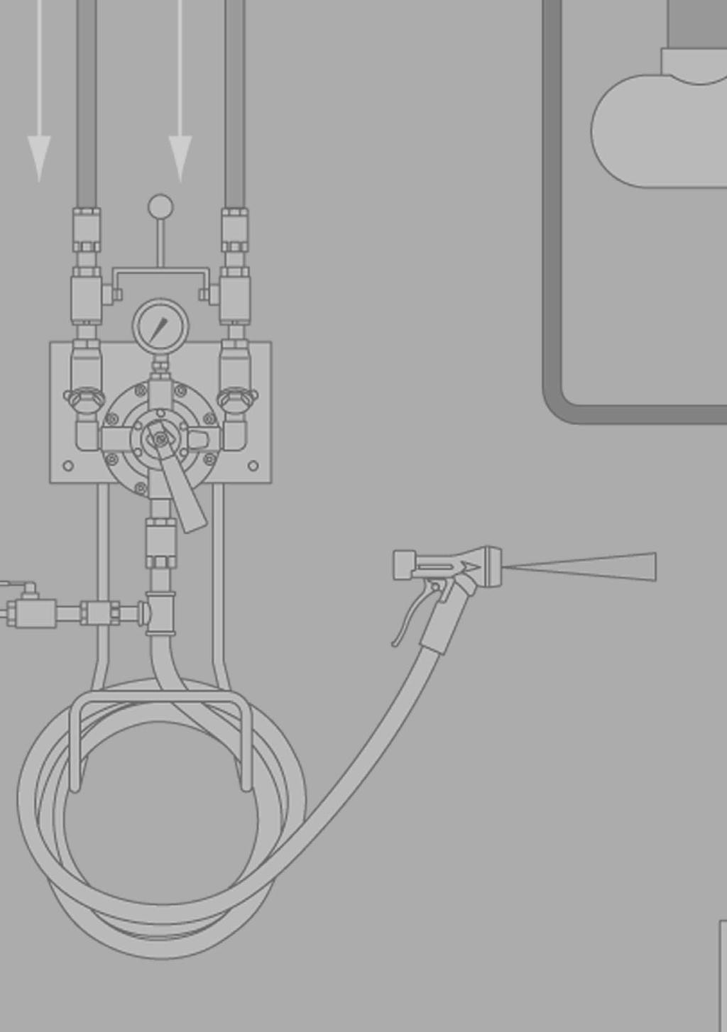
394
395 Strainers

396 Strainer Tight seating Both ends of the chamber are precisey machined to provide perfecty round and smooth seating surfaces as we as fixed chamber ength. The screen seats snugy on the machined surface so no partice arger than the screen opening can escape around the end of the screen. Choice of body materias Cast iron, carbon stee, chrome moy, forged stee, stainess stee, bronze. Connection configurations avaiabe Seect screwed, socketwed or fanged. Strainers Choice of mesh 30 x 30 (CA Series strainers ony) or 0,045'' perforated stainess stee screens. Other screen materias, meshes and perforations avaiabe. Easy-in, easy-out screwed screen retainers Straight threads mean ess torque is required to obtain a tight sea with proper gasket compression, and ess torque is required to remove the retainer. The danger of freezing in is consideraby ess than with hard-to-break tapered pipe threads. S-388
397 Armstrong Y-Type Strainers Design Advantages No-Leak, No-Crush Screen Chambers are assured by precise machining of both ends of the chamber to provide perfecty round and smooth seating surfaces as we as fixed chamber ength. The screen seats snugy on the machined surface so no partice arger than the screen opening can escape around the end of the screen. Easy-In, Easy-Out Screwed Screen Retainers have straight threads. Less torque is required to obtain a tight sea with proper gasket compression. Less torque is required to remove the retainer. The danger of freezing in is consideraby ess than with hard-to-break tapered pipe threads. Off-Center Bowdown Connections for 2 1/2'' and 3'' size strainers. The off-center drain permits neary compete remova of iquid and dirt when bowing down the strainer. And ess iquid spis when removing the screen retainer. How To Order Mode Number A FL 125 CONNECTION SIZE (inches) BODY MATERIAL CA = Cast Iron ASTM A48 C. 30 (Screwed 1/2'', 3/4'', 1'', 1 1/4'', 1 1/2'', 2'') A = Cast Iron ASTM A48 C. 30 (Screwed 2 1/2'', 3'') B = Cast Carbon Stee ASTM A216 Gr. WCB C = Cast Chrome Moy Stee ASTM A217 Gr. WC6 D = Forged Stee ASTM A182 Gr. F22 E = Cast 316 Stainess Stee ASTM A351 Gr. CF8M F = Cast Bronze ASTM B62 SC = Screwed FL = Fanged SW = Socketwed ANSI FLANGE CLASS CONNECTION CONFIGURATION Strainers SCREEN MATERIAL Pease refer to tabe at top of page S-393 for appicabe screen code. S-389
398 Strainers ID Charts Tabe S Armstrong Strainers Iustration Mode Connection Size Connection Type Body Materia Pressure Temperature Ratings Steam Non-shock Cod Non-shock Located on Page CA 1/2", 3/4", 1", 1 1/4", 1 1/2", 2" S-394 Screwed C C A 2 1/2", 3" S-394 A 2" A 2 1/2" - 10" A 2" A 2 1/2" - 8" Cast Iron ASTM-A48 Cass 30 Cass 125 Fanged 8,6 178 C C Cass 250 Fanged C C S-395 B 1/2", 3/4", 1" Screwed & Socketwed 900 b C C S-396 B 1 1/4", 1 1/2", 2", 3" Screwed & Socketwed 600 b C C B 1/2", 3/4", 1" B 1 1/4", 1 1/2", 2", 3" B 4", 6" B 1/2", 3/4", 1" B 1 1/4", 1 1/2", 2", 3" Cass 150 Fanged C C Cast Carbon Stee ASTM-A216 Gr. WCB Cass 300 Fanged C C S-397 Strainers B 4", 6" B 1/2", 3/4", 1" B 1 1/4", 1 1/2", 2", 3" B 4" Cass 600 Fanged C C C 1/2", 3/4", 1" C C Screwed & Socketwed b C 1 1/4", 1 1/2", 2" C C Cast Chrome Moy Stee ASTM-A217 Gr. WC6 C 1/2", 3/4", 1" C C S-398 Cass Fanged C 1 1/4", 1 1/2", 2" C C D 1/2", 3/4", 1", 1 1/4", 1 1/2", 2" Socketwed b Forged Stee ASTM-A182 Gr. F C C S-399 S-390
399 Strainers ID Charts Tabe S Armstrong Strainers Iustration Mode Connection Size Connection Type Body Materia Pressure Temperature Ratings Steam Non-shock Cod Non-shock Located on Page E 1/2", 3/4", 1" Screwed & Socketwed b C C S-400 E 1 1/4", 1 1/2", 2", 3" E 1/2", 3/4", 1" E 1 1/2", 2", 3" E 4", 6" E 1/2", 3/4", 1" E 1 1/2", 2", 3" E 4", 6" E 1/2", 3/4", 1" E 1 1/2", 2", 3" E 4" Screwed & Socketwed 600 b C C Cast Stainess Stee Cass 150 Fanged ASTM-A351 Gr. CF8M C C Cass 300 Fanged C C Cass 600 Fanged C C S-401 F 1/2", 3/4", 1", 1 1/4" Screwed 300 b Cast Bronze ASTM-B C C S-402 F 1 1/2", 2" A modes compy with the Pressure Equipment Directive PED 97/23/EC. For detais, see specific product page or Armstrong PED Certificate. Strainers S-391
400 Notes Strainers S-392
401 Screen Data Tabe S Screen Materia Avaiabiity and Partice Retention Size Screen Specification Perforated Mesh Partice Retention mm Back-Up Screen Required Materias 304 SS Mone Brass 316 SS 1/64" 0,4064 3" 10" Code 10 Code 18 1/32" 0,7874 None Code 11 Code 19 Code 31 0,045 (3/64") 1,1430 None Code 1 Code 3 Code 4 Code 7 1/16" 1,5748 None Code 12 Code 32 1/8" 3,1750 None Code 8 Code 21 Code 28 Code 33 3/16" 4,7752 None Code 13 Code 22 Code 34 1/4" 6,3500 None Code 14 Code 23 Code x 20 0,8636 6" 10"* Code 15 Code 5** 24 x 110 0,1422 5" 10" Code 24 Code 2 30 x 30 0,5080 None Code 41 (1) 40 x 40 0, /2" 10" Code 16 Code 6 Code x 100 0,1397 A sizes Code 9 Code 25 Code x 150 0,1041 A sizes Code x 200 0,0737 A sizes Code 17 Code 39 * Except 6" 125 b cast iron ** On Code 5 2 1/2" thru 10 " require back-up screen Shade indicates ony avaiabe screen choices for CA Series Strainers. (1) 30 x 30 mesh screen ony avaiabe for CA Series Strainers. Tabe S Ratio of Open Area of Screen to Inside Area of Pipe Strainer Tota Screen Inside Area of Ratio Perforated Screens Ratio Wire Mesh Screens Size Area, cm² Pipe, cm² 1/64" 1/32" 0,045" 1/16" 1/8" 3/16" 1/4" 24 x x x x x x 200 1/2" 46,45 1,94 5,2 5,0 6,4 (5) 5,2 6,9 (5,4) 8,8 10,0 4,8 (3,8) 6,6 7,2 5,2 (4,1) 2,2 (1,8) 2,5 3/4" 46,45 3,42 4,0 3,9 5,0 4,0 5,4 6,9 7,8 3,8 5,3 7,2 4,1 1,8 2,0 1" 70,97 5,55 3,8 3,7 4,7 3,8 5,1 6,5 7,4 3,7 5,2 11,0 4,0 1,7 1,9 1 1/4" 102,6 9,61 3,2 3,0 3,9 3,2 4,2 5,4 6,1 3,2 4,4 3,4 1,5 1,6 1 1/2" 152,3 13,10 3,4 3,3 4,3 3,4 4,6 5,9 6,7 3,5 4,8 23,6 2,8 1,6 1,8 2" 221,9 21,61 3,0 2,9 3,8 3,0 4,1 5,2 5,9 3,2 4,4 34,4 2,6 1,5 1,6 2 1/2" 351,0 30,84 3,4 3,3 4,2 3,4 4,5 5,8 6,6 3,3 3,5 2,7 1,7 1,9 3" 125# 477,4 47,68 1,7 2,9 3,7 3,0 4,0 5,1 5,8 2,9 3,1 2,3 1,5 1,7 3" 250# 561,3 47,68 2,0 3,4 4,3 3,5 4,7 6,0 6,8 3,5 3,8 2,8 1,8 2,0 4" 125# 793,5 81,94 1,7 2,8 3,5 2,9 3,8 4,9 5,6 2,8 3,0 2,3 1,5 1,6 4" 250# 935,5 81,94 2,0 3,3 4,2 3,4 4,5 5,8 6,6 3,4 3,7 2,1 1,8 2,0 6" 125# ,5 1,6 2,7 3,4 2,8 3,1 4,8 5,4 1,6 3,0 1,8 1,5 1,6 6" 250# ,5 1,9 3,1 4,0 3,2 4,3 5,5 6,3 1,9 2,7 2,1 1,7 1,9 8" 125# ,6 1,6 2,6 3,4 2,7 3,7 4,7 5,3 1,6 2,3 1,8 1,5 1,7 8" 250# ,6 1,9 3,1 4,0 3,3 4,4 5,6 6,3 2,0 2,8 2,1 1,8 2,0 10" 125# ,4 1,6 2,7 3,4 2,7 3,7 4,7 5,4 1,7 2,3 1,8 1,5 1,7 Percentage Open Area 30%* 29% 37% 30% 40% 51% 58% 33%* 46%* 37% 36%* Notes: Cast stee, stainess stee and bronze strainers have the same ratios as 250 b cast iron. This tabe does not appy to the Forged Stee F22 Strainers on page S-399. Numbers in parentheses appy to CA cast iron series ony. * For unbacked screens. Back-up required, Mone ony. Shade indicates that back-up screens are required. Strainers S-393

402 Cast Iron 250 b Screwed 1/2'' - 3'' CA1SC/CA41SC 1/2", 3/4", 1", 1 1/2", 2" CA1SC/CA41SC 1 1/4" A1SC 2 1/2", 3" Pressure/Temperature Rating Pressure, barg Temperature, C Strainers Tabe S Materias: 250 b Screwed 1/2" - 3" Connection Size Body Standard Screen Screen Retainer Gasket Boting in 1/2", 3/4" ASTM A48 30x30 SS Mesh or 304 SS ASTM A48 Spira wound 1", 1 1/2", 2" N/A Cass 30 0,045" perforated Cass /4" Soft Stee Cast Iron Cast Iron 2 1/2", 3" 304 SS 0,045" perforated Non-asbestos Cap Screws ASTM A193 Gr. B7 Note: Other screen materias avaiabe. See page S-393. Tabe S Physica Data: 250 b Screwed 1/2" - 3" Connection Size Ordering Code, Standard Screen Weight Dimensions A B C Saturated Steam Maximum Pressure 66 C non-shock in kg mm mm in bar bar 1/2" 3/4" 1, /8" 1" CA1SC 2, /4" CA41SC 3, /2" 4, /2" " 6, /2" 11, /4" A1SC 3" 21, /4" A sizes compy with the artice 3.3 of the PED (97/23/EC). Screen Retainer Type Threaded Boted Connections ANSI B Screwed A dimensions and weights are approximate. Use certified print for exact dimensions. Design and materias are subject to change without notice. S-394

403 Cast Iron Cass 125 Fanged 2'' - 10'' and Cass 250 Fanged 2'' - 8'' 2'' Cass 125 or 250 Fanged 2 1/2'' - 10'' Cass 125 Fanged, 2 1/2'' - 8'' Cass 250 Fanged Tabe S Materias: Cass 125 Fanged 2" - 10" and Cass 250 Fanged 2" - 8" Connection Size Body Screen Retainer Gasket Boting Standard screen in 2" ASTM A48 N/A Soft Stee 304 SS 0,045" perforated 2 1/2", 3", 4", 6", 8" Cass 30 Cap Screws ASTM A193 10" Cass 125 Ony Cast Iron Non-asbestos 304 SS 1/8" perforated Note: Other screen materias avaiabe. See page S-393. Strainers Tabe S Physica Data: Cass 125 Fanged 2" - 10" and Cass 250 Fanged 2" - 8" Connection Ordering Dimensions Maximum Pressure Size Code, Weight Screen Saturated 66 C A B C Retainer Standard Steam non-shock Type in Screen kg mm mm in bar bar 2" /2" Threaded 2 1/2" /4" A1FL 125 8,6 12 3" /4" Boted 4" /4" 6" /2" A1FL 125 8" " 8,6 12 Boted 10" A8FL " 2" A1FL /2" Threaded 2 1/2" /4" 3" /4" 4" A1FL /4" Boted 6" /2" 8" " Shade indicates products that are CE Marked according to the PED (97/23/EC). A the other sizes compy with the Artice 3.3 of the same directive. Connection Cass 125 ANSI B16.1 Fat Faced Cass 250 ANSI B16.1 1/16" RF A dimensions and weights are approximate. Use certified print for exact dimensions. Design and materias are subject to change without notice. S-395

404 Cast Carbon Stee (WCB) 600 b and 900 b Screwed or Socketwed 1/2'' - 3'' 900 b B1SC/B1SW 1/2'', 3/4'', 1'' 600 b B1SC/B1SW 1 1/4'', 1 1/2'', 2'', 3'' Pressure/Temperature Rating 1/2" - 3/4" - 1" Scrd. & SW Pressure, barg 1 1/4" - 3" Scrd. & SW, 1/2" - 4" C. 600 Fanged 1/2" - 6" C. 300 Fanged 1/2" - 6" C. 150 Fanged Temperature, C Strainers Tabe S Materias: 600 b and 900 b Screwed or Socketwed 1/2" - 3" Connection Size in Body Screen Retainer Gasket Boting Standard Screen 1/2", 3/4" ASTM A108 Gr Soft Stee N/A 1" ASTM A216 ASTM A108 Gr Gr. WCB 304 SS Spira Wound Studs ASTM A193 Gr. B7 1 1/4", 1 1/2", 2" ASTM A216 Gr. WCB Non-asbestos Nuts ASTM A194 Gr. 2H 3" Non-asbestos Cap screws ASTM A193 Gr. B7 Note: Other screen materias avaiabe. See page S SS 0,045" Perforated Tabe S Physica Data: 600 b and 900 b Screwed or Socketwed 1/2" - 3" Dimensions Connection Ordering Code Weight Size Standard Screen A B C Maximum Pressure Saturated Steam 38 C non-shock Screen Retainer Type in Screwed SW kg mm mm in bar bar 1/2" 1, /8" 3/4" B1SC B1SW 1, " 2, /2" 1 1/4" 4, /2" 5, /2" B1SC B1SW 2" 9, Boted 3" 21, /4" Connections Threaded ANSI B Screwed Shade indicates products that are CE Marked according to the PED (97/23/EC). A the other sizes compy with the Artice 3.3 of the same directive. ANSI B16.11 Socketwed A dimensions and weights are approximate. Use certified print for exact dimensions. Design and materias are subject to change without notice. S-396
405 Cast Carbon Stee (WCB) Cass 150, 300 Fanged 1/2'' - 6'' and Cass 600 Fanged 1/2'' - 4'' B1FL 1/2'', 3/4'', 1'' B1FL 1 1/4'', 1 1/2'', 2'', 3'' B1FL 4'', 6'' Tabe S Materias: Cass 150, 300 Fanged 1/2" - 6" and Cass 600 Fanged 1/2" - 4" Connection Size Body Screen Retainer Gasket Boting in 1/2", 3/4" ASTM A108 Soft Stee N/A 1" Gr ASTM A /4", 1 1/2", 2" Gr. WCB 304 SS Spira wound Studs ASTM A193 Gr. B7 ASTM A216 Non-asbestos Nuts ASTM A194 Gr. 2H Gr. WCB 3", 4", 6" Non-asbestos Cap Screws ASTM A193 Gr. B7 Note: Other screen materias avaiabe. See page S-393. Standard screen 304 SS 0,045" Perforated Tabe S Physica Data: Cass 150, 300 Fanged 1/2" - 6" and Cass 600 Fanged 1/2" - 4" Connection Ordering Dimensions Maximum Pressure Size Code, Weight Screen Saturated 38 C A B C Retainer Standard Steam non-shock Type in Screen kg mm mm in bar bar 1/2" 2, /8" 3/4" 4, Threaded 1" 4, B1FL /4" 7, /2" /2" 9, Boted 2" 13, " 37, /4" 4" B1FL , Boted 6" 125, /2" 1/2" 3, /8" 3/4" 5, Threaded B1FL " 6, /2" 1 1/4" 8, Boted 1 1/2" 12, /2" 2" 15, " B1FL , Boted 1 1/4" 4" 59, " 137, /2" 1/2" 5, /8" 3/4" B1FL 600 5, " 6, /2" 1 1/4" 8, /2" 13, /2" 2" B1FL , " 43, " 69, /4" Threaded Boted Note: For pressure/temperature ratings, see page S-396. Shade indicates products that are CE Marked according to the PED (97/23/EC). A the other sizes compy with the Artice 3.3 of the same directive. Fanges Cass 150 ANSI B16.5 1/16" RF Cass 300 ANSI B16.5 1/16" RF Cass 600 ANSI B16.5 1/4" RF Strainers A dimensions and weights are approximate. Use certified print for exact dimensions. Design and materias are subject to change without notice. S-397
406 Cast Chrome Moy Stee (WC6) b Screwed, Socketwed and CI Fanged 1/2'' - 2'' C1SC/C1SW 1/2'', 3/4'', 1'' C1SC/C1SW 1 1/4'', 1 1/2'', 2'' C1FL 1/2'', 3/4'', 1'' Pressure/Temperature Rating 1 1/4" - 1 1/2" - 2" Pressure, barg 1/2" - 3/4" - 1" C1FL 1 1/4'', 1 1/2'', 2'' Temperature, C Strainers Tabe S Materias: b Screwed, Socketwed and Cass Fanged 1/2" - 2" Connection Size in Body Screen Retainer Gasket Boting Standard Screen 1/2", 3/4", 1" ASTM A276 Soft Stee N/A ASTM A /4", 1 1/2", 2" Gr. WC6 ASTM A217 Gr. WC6 Note: Other screen materias avaiabe. See page S L SS Spira Wound Non-asbestos Studs ASTM A193 Gr. B16 Nuts ASTM A194 Gr. 2H 304 SS 0,045" perforated Tabe S Physica Data: b Screwed, Socketwed and Cass Fanged 1/2" - 2" Dimensions Connection Ordering Code Weight Size Standard Screen A B C Maximum Pressure Saturated Steam 38 C non-shock in Screwed SW kg mm mm in bar bar 1/2" C1SC C1SW 1, /8" 3/4" C1SC C1SW 1, /2" 1" C1SC C1SW 2, /2" 1 1/4" C1SC C1SW* 8, /4" 1 1/2" C1SC C1SW* 8, /4" 2" C1SC C1SW* 11, " 1/2" C1FL , /8" 3/4" C1FL , /2" 1" C1FL , /2" 1 1/4" C1FL 1500* 17, /4" 1 1/2" C1FL 1500* 20, /4" 2" C1FL 1500* 35, " Screen Retainer Type Threaded Boted Threaded Boted * Socketwed Bowdown Connections. Shade indicates products that are CE Marked according to the PED (97/23/EC). A the other sizes compy with the Artice 3.3 of the same directive. Connections ANSI B Screwed ANSI B16.11 Socketwed Cass 1500 ANSI B16.5 1/4" RF A dimensions and weights are approximate. Use certified print for exact dimensions. Design and materias are subject to change without notice. S-398

407 Forged Stee (F22) b Socketwed 1/2'' - 2'' D1SW 1/2'' - 2'' Pressure/Temperature Rating Pressure, barg Temperature, C Tabe S Materias: b Socketwed 1/2" - 2" Connection Size Body Screen Retainer Gasket Boting Standard Screen in 1/2", 3/4", 1", 1 1/4", 1 1/2", 2" ASTM A182 Gr. F22 Note: Other screen materias avaiabe. See page S-393. ASTM A182 Gr. F SS Spira Wound Non-asbestos Studs ASTM A193 Gr. B16 Nuts ASTM A194 Gr. 2H 304 SS 0,045" Perforated Strainers Tabe S Physica Data: b Socketwed 1/2" - 2" Connection Size Ordering Code, Standard Screen Weight Dimensions A B C* Saturated Steam Maximum Pressure 38 C non-shock in kg mm mm in bar bar 1/2" 3/4" 1" 1 1/4" 1 1/2" 2" Screen Retainer Type D1SW /2" Boted D1SW /2" Boted * Socketwed bowdown connections for 1/2" pipe. Shade indicates products that are CE Marked according to the PED (97/23/EC). A the other sizes compy with the Artice 3.3 of the same directive. Connections ANSI B16.11 Socketwed A dimensions and weights are approximate. Use certified print for exact dimensions. Design and materias are subject to change without notice. S-399

408 Cast Stainess Stee (CF8M) b and 600 b Screwed, Socketwed 1/2'' - 3'' E7SC/E7SW 1/2'', 3/4'', 1'' E7SC/E7SW 1 1/4'', 1 1/2'', 2'', 3'' Pressure/Temperature Rating 1/2" - 1" Screwed & Socketwed Pressure, barg 1 1/4" - 3" Scrd. & SW & 1 1/2" - 4" C. 600 Fanged 1 1/2" - 6" C. 300 Fanged 1/2" - 6" C. 150 Fanged Temperature, C Strainers Tabe S Materias: b and 600 b Screwed or Socketwed 1/2" - 3" Connections Size in Body Screen Retainer Gasket Boting Standard Screen 1/2", 3/4", 1" ASTM A SS Fat N/A ASTM A SS Spira Wound Studs ASTM A193 Gr. B7 316 SS 0,045" 1 1/4", 1 1/2", 2" ASTM A351 Gr. CF8M Non-asbestos Nuts ASTM A194 Gr. 2H perforated Gr. CF8M 3" Non-asbestos Cap screws ASTM A193 Gr. B7 Note: Other screen materias avaiabe. See page S-393. Tabe S Physica Data: b and 600 b Screwed or Socketwed 1/2" - 3" Dimensions Connection Ordering Code Weight Size Standard Screen A B C Maximum Pressure Saturated Steam 38 C non-shock Screen Retainer Type in Screwed SW kg mm mm in bar bar 1/2" 1, /8" 3/4" E7SC E7SW 1, " 3, /2" 1 1/4" 4, /2" 5, /2" E7SC E7SW 2" 9, Boted 3" 23, /4" Connections Threaded ANSI B Screwed Shade indicates products that are CE Marked according to the PED (97/23/EC). A the other sizes compy with the Artice 3.3 of the same directive. ANSI B16.11 Socketwed A dimensions and weights are approximate. Use certified print for exact dimensions. Design and materias are subject to change without notice. S-400
409 Cast Stainess Stee (CF8M) C. 150, 300 Fanged 1/2'' - 6'' and C. 600 Fanged 1/2'' - 4'' E7FL 1/2'', 3/4'', 1'' E7FL 1 1/2'', 2'', 3'' E7FL 4'', 6'' Tabe S Materias: Cass 150, 300 Fanged 1/2" - 6" and Cass 600 Fanged 1/2" - 4" Connection Size in Body Screen Retainer Gasket Boting Standard Screen 1/2", 3/4", 1" ASTM A SS Fat N/A ASTM A SS Spira Wound Studs ASTM A193 Gr. B7 316SS 0,045" 1 1/2", 2" ASTM A351 Gr. CF8M Non-asbestos Nuts ASTM A194 Gr. 2H perforated Gr. CF8M 3", 4", 6" Non-asbestos Cap Screws ASTM A193 Gr. B7 Note: Other screen materias avaiabe. See page S-393. Tabe S Physica Data: Cass 150, 300 Fanged 1/2" - 6" and Cass 600 Fanged 1/2" - 4" Connection Ordering Dimensions Maximum Pressure Size Code, Weight Saturated 38 C A B C Standard Team non-shock in Screen kg mm mm in bar bar Screen Retainer Type Fanges 1/2" 2, /8" 3/4" 4, Threaded 1" E7FL 150 5, /2" 1 1/2" 9, ANSI B16.5 Boted 2" 11, /16" RF 3" 25, /4" 4" E7FL , Boted 6" /2" 1/2" 3, /8" 3/4" E7FL 300 4, Threaded 1/2" 1" 6, /2" 10, ANSI B16.5 1/2" 2" 15, /16" RF 3" E7FL , Boted 1 1/4" 4" 65, " 137, /2" 1/2" 4, /8" 3/4" E7FL 600 4, Threaded 1/2" 1" 6, ANSI B /2" 12, /2" 1/4" RF 2" 14, E7FL Boted 3" 34, /4" 4" 69, Note: For pressure/temperature ratings, see page S-400. Shade indicates products that are CE Marked according to the PED (97/23/EC). A the other sizes compy with the Artice 3.3 of the same directive. Strainers A dimensions and weights are approximate. Use certified print for exact dimensions. Design and materias are subject to change without notice. S-401

410 Cast Bronze 300 b Screwed 1/2'' - 2'' F4SC 1/2''- 2'' Temperature, C Strainers Pressure, barg Tabe S Materias: 300 b Screwed 1/2" - 2" Connection Size in Body Screen Retainer Gasket Boting Standard Screen 1/2", 3/4", 1", 1 1/4", 1 1/2", 2" ASTM B62 Brass Copper N/A Brass 0,045" perforated Note: Other screen materias avaiabe. See page S-393. Tabe S Physica Data: 300 b Screwed 1/2" - 2" Connection Size Ordering Code, Standard Screen Weight Dimensions A B C Maximum Pressure Saturated Steam 66 C non-shock Screen Retainer Type in kg mm mm in bar bar 1/2" 0, /8" 3/4" 0, " F4SC 1, Threaded 1/2" 1 1/4" 2, /2" 3, " F4SC 5, /2" Threaded Shade indicates products that are CE Marked according to the PED (97/23/EC). A the other sizes compy with the Artice 3.3 of the same directive. Connections ANSI B Screwed A dimensions and weights are approximate. Use certified print for exact dimensions. Design and materias are subject to change without notice. S-402
411 Water Fow Capacities Tabe S Water Fow Capacities in m³/h Pressure Drop, bar Strainer Size, Inches Armstrong Y-Type Strainers Master Seection Tabe Tabe S Master Seection Tabe Materia Connections Sizes Pressure - Temperature Ratings in Steam, Non-Shock Cod, Non-Shock Cast Iron Screwed b 1/2" - 3" C C ASTM A48 Cass 125 Fanged 2" - 10" 8,6 178 C C Cass 30 Cass 250 Fanged 2" - 8" C C Cast Carbon Stee ASTM A216 Gr. WCB Cast Chrome Moy Stee ASTM A217 Gr. WC6 Forged Stee ASTM A182 Gr. F22 Cast SS ASTM A351 Gr. CF8M Cast Bronze ASTM B62 Screwed & Socketwed b 1/2" - 1" C C Screwed & Socketwed b 1 1/4" - 3" C C Cass 150 Fanged 1/2" - 6" C C Cass 300 Fanged 1/2" - 6" C C Cass 600 Fanged 1/2" - 4" C C Screwed & Socketwed b 1/2" - 1" C C Screwed & Socketwed b 1 1/4" - 2" C C Cass Fanged 1/2" - 1" C C Cass Fanged 1 1/4" - 2" C C Socketwed b 1/2" - 2" C C Screwed & Socketwed b 1/2" - 1" C C Screwed & Socketwed b 1 1/4" - 3" C C Cass 150 Fanged 1/2" - 6" C C Cass 300 Fanged 1/2" - 6" C C Cass 600 Fanged 1/2" - 4" C C Screwed b 1/2" - 2" C C Strainers S-403
412
413 Tab Guide Condensate Guideines Pages CG-8 CG-63 Steam Traps and Steam Trap Management Products Services.....Pages ST-66 ST-183 Steam Tracing Equipment Pages STE-186 STE-207 Condensate Recovery Equipment Pages CRE-210 CRE-261 Pressure and Temperature Contro Pages PTC-264 PTC-315 Water Heating Pages WH-318 WH-343 Water Mixing Pages WM-346 WM-365 Unit and Tank Heaters Pages C-368 C-385 Strainers Pages S-388 S-403 Air Vents Pages AV-406 AV-425 Guideines for Draining Liquids Pages LD-428 LD-453 Liquid Drainers Pages LD-454 LD-479 Anciary Products Pages AC-482 AC-485 Training and Warranty Pages TW-488 TW-491 TOC-3
414 Tabe of Contents Engineering Guideines Steam Conservation Guideines CG-8 CG-63 Condensate Recovery Guideines CRE-210 CRE-216 Water Heating Guideines WH-318 WH-323 Draining Liquids From Compressed Air & Other Gases LD-428 LD-453 Steam Traps and Steam Trap Management Products Services....ST-66 ST-183 Steam Trap ID Charts ST-67 Inverted Bucket Steam Traps ST-72 Trap Vave Stations ST-84 / ST-112 Foat & Thermostatic Steam Traps ST-122 Controed Disc Steam Traps ST-148 Bimetaic Steam Traps ST-154 Thermostatic Wafer Steam Traps ST-160 Thermostatic Beows Steam Traps ST-166 Cean Steam Traps ST-168 Steam Trap Options & Connectors ST-169 SteamEye ST-174 SteamStar TM ST-174 Steam Tracing Equipment STE-185 STE-207 Steam Tracing Equipment ID Charts STE-186 Manifods for Steam Distribution STE-190 Manifods for Condensate Coection STE-192 Trap Vave Station STE-194 Steam Traps used with the Universa Connector STE-196 Insuation Jackets STE-206 Condensate Recovery Equipment CRE-209 CRE-261 Pumping Trap ID Charts CRE-212 Mechanica Pumping Traps and Packages CRE-218 Steam Trap/Pump Combination CRE-234 Fash Recovery Vesses CRE-256 Posi-Pressure Draining System CRE-250 Thermosiphon Mixer (MTS) CRE-258 Pressure and Temperature Contros PTC-263 PTC-315 Pressure and Temperature Contro ID Charts PTC-265 Pressure Reducing Vaves PTC-266 Cycone Separators PTC-283 Temperature Reguators PTC-284 Contro Vaves PTC-294 Water Heating WH-317 WH-342 Water Heating ID Charts WH-324 Instantaneous Water Heaters WH-327 She & Tube Heat Exchangers WH-334 Cean-in-Pace Scae Remova System WH-339 TOC-4
415 Tabe of Contents Fo-Direct Direct Fired Water Heater WH-341 Water Mixing WM-345 WM-365 Washdown Equipment & Accessories ID Charts WM-347 Steam Hose Stations & Mixing Units WM-348 Fow Indicator WM-354 Washdown Equipment WM-356 MegaMix TM Water Temperature Mixing Units WM-358 MegaMix TM Steam/Water Temperature Mixing Units WM-363 Unit & Tank Heaters (Cois) C-367 C-385 Unit Heaters C-368 Hot Breath TM Heaters C-372 Hot Bin TM Heaters C-372 Duramix TM Heating Cois C-373 Tank Heaters C-375 Strainers S-387 S-403 Strainer ID Charts S-390 Screen Data S-393 Strainers S-394 Air Vents AV-405 AV-425 Air Vent ID Charts AV-408 Air Vents AV-410 Liquid Drainers LD-428 LD-479 Liquid Drainer ID Charts LD-455 Liquid Drainers LD-458 Anciary Products ANC-481 ANC-485 Stainess Stee Sump Ejector ANC-482 Condensate Cooers ANC-484 MS-6 Noiseess Heater ANC-485 Training and Warranty TW-487 TW-494 Training Seminars TW-488 Web Site TW-489 Warranty TW-491 Trademark Information TW-491 Armstrong Mode Number Index TW-492 TOC-5
416 Tabe of Contents by System Steam Systems Steam Traps...ST-66 Cois...C-375 Condensate Pumping Traps...CRE-210 Pressure Reducing Vaves...PTC-266 Temperature Reguators...PTC-284 Cycone Separators...PTC-283 Thermostatic Air Vents...AV-420 Fash Recovery Vesses...CRE-256 Water Heaters...WH-318 Washdown Stations...WM-348 Strainers...S-388 Steam Tracing Manifods...STE-190 Steam Trap Testing and Monitoring Devices...ST-174 Unit Heaters...C-367 Condensate Recovery Systems Condensate Pumping Traps and Packages...CRE-210 Fash Recovery Vesses...CRE-256 Posi-Pressure Draining System...CRE-258 Steam Tracing Condensate Manifods...STE-192 Stainess Stee Sump Ejector...ANC-482 Compressed Air Systems Liquid Drainers...LD-458 Strainers...S-388 Pressure Reducing Vaves...PTC-266 Cycone Separators...PTC-283 Process Air Heating Cois...C-375 Condensate Pumping Traps...CRE-211 Steam Traps...ST-66 Pressure Reducing Vaves...PTC-266 Temperature Reguators...PTC-284 Strainers...S-388 Thermostatic Air Vents...AV-420 Hot Water Systems Instantaneous Water Heaters...WH-327 She & Tube Heat Exchangers...WH-336 Air Vents...AV-406 Pressure Reducing Vaves...PTC-266 Temperature Reguators...PTC-284 Strainers...S-388 Instantaneous Water Heater Packages...WH-331 TOC-6
417 Tabe of Contents by System HVAC Systems Condensate Pumping Traps...CRE-211 Steam Traps...ST-66 Pressure Reducing Vaves...PTC-266 Temperature Reguators...PTC-284 Thermostatic Air Vents...AV-420 Strainers...S-388 Posi-Pressure Draining System...CRE-258 Hydronic/Radiant Systems Air Vents...AV-406 Instantaneous Water Heater Packages...WH-331 Liquid Drainers...LD-458 Strainers...S-388 Temperature Reguators...PTC-284 TOC-7

418 Tank Heaters
419 Features/Benefits of Armstrong Tank Heaters Appication Fexibiity Four types of tank heaters are offered in severa materias and sizes to suit your specific requirements. Fange Mounted Bayonet Type FBC and FBS Space Savings Fange mounted heaters are instaed on various standard manhoe sizes. You save interna space because ony the heating eement itsef is inside. Steam and condensate connections are outside of the tank. Heat Transfer Efficiency Stiff, heicay wound L fin design for an efficient and ong-asting heat transfer surface. Vertica fin surface provides uniform heating of iquid with a minimum of coking due to hot spots. Base Mounted Direct Type BD Unit & Tank Heaters Fange Mounted Hairpin Type FHC and FHS Durabiity Over Long Life Pipes and headers are of heavy construction (minimum Sch. 40 pipe for stee). Greater thickness means a stronger, more corrosion-resistant design that asts onger. Corrosion Resistance Pipes, headers and connections are weded together for a tough, singe materia joint. Eiminating dissimiar materias precudes gavanic corrosion, thereby engthening service ife. C-376
420 Base Mounted Hairpin Types BHC and BHS Shown Unit & Tank Heaters Fast, Direct Connection Heaters are ready for connection to the steam and condensate systems as suppied. Numerous types of connections are avaiabe. Base mounted heaters come with supports to aow for a proper distance between the tank bottom and the heating surface. This aso heps to minimize the need for interna weding. Longer units are provided with mid-support members to further minimize inside weding and ensure rigid footing. Minimum Instaation Weding Armstrong base-mounted tank heaters are instaed and removed easiy through manhoes, eiminating the need for time-consuming weding inside the tank. C-377

421 Tougher on the Job Unit & Tank Heaters Armstrong tank heaters are buit to withstand the rigorous demands encountered in industria instaations. The heavy-duty features of our units were deveoped in response to a need for tank heaters that coud provide efficient heat transfer without sacrificing structura integrity. These features incude heavy-wa pipes and headers, thick L footed fins and a weded construction. In addition, the mono-metaic construction of our units precudes gavanic corrosion, and the finned surface is rigid enough to withstand high-pressure ceaning. Experience gained over 80 years backs every Armstrong tank heater. As a steam system speciaist, your Armstrong Representative can provide assistance with everything from the boier to the condensate return system. Quaity products from Armstrong, pus the practica knowedge to integrate them into your tota steam system, ensure an efficient and troube-free instaation. Efficient Heat Transfer Finned pipe tank heaters are easier than bare pipe units to insta, remove and repair. They are aso more compact and provide superior efficiency in product heating. Finned pipe tank heaters provide up to 10 times as much heat transfer as an equivaent ength of bare pipe, resuting in ower fim or "skin" temperatures. This reduces coking of the product on the heat transfer surface and discooration of heat-sensitive products. This buidup of deposits on the heater requires that more frequent ceanings be carried out to maintain maximum efficiency and origina heat transfer design conditions. This heicay wound finned pipe is best suited for horizonta units, with the fins being in the vertica pane. This increases the natura convection currents, which increases heat transfer and continuousy wipes the coi surface to maintain ceaniness. Options to Match Your Appications Armstrong tank heaters are avaiabe in four standard configurations: Fange Mounted Hairpin Types FHC and FHS Fange Mounted Bayonet Types FBC and FBS Base Mounted Hairpin Types BHC and BHS Base Mounted Direct Type BD These four configurations offer a range of choices to suit most area coverage and therma performance requirements. Each type incudes a number of ength, width and fin pitch options. A units are avaiabe in seamess carbon stee pipe construction. The hairpin and bayonet types are avaiabe in stainess stee. Liquid heated units and custom designs are aso avaiabe. Critica to the heating and maintenance of temperatures for a broad variety of products, Armstrong tank heaters are widey used in breweries, chemica and food processing pants, oi refineries, paper mis, tank storage farms, and in shipping and other industries. From eft to right, Base Mounted Hairpin, Fange Mounted Bayonet, Fange Mounted Hairpin and Base Mounted Direct. C-378
422 Mode Number Seection MODEL NUMBER BH S 6 4 FPI 20 TYPE OF TANK HEATER FH = Fange Mounted Hairpin FB = Fange Mounted Bayonet BH = Base Mounted Hairpin BD = Base Mounted Direct NOMINAL LENGTH L mm FINS PER mm MATERIALS OF CONSTRUCTION C = Carbon Stee S = 304L or 316L Stainess Stee UNIT NUMBER Number of Finned Pipes For Types FHC, FHS, BHC, BHS, BD or Pipe Size For Types FBC, FBS Unit & Tank Heaters C-379
423 Fange Mounted Hairpin Type FHC and FHS Overa = "L" mm "L" mm "L" "B" Support by Others "A" NPS 14 mm x 101,6 mm Long Sot Standard Sizes Unit & Tank Heaters Tabe C FHC Carbon Stee Units Type A Fange size (mm) FHC FHC Nomina B Surface area (m²) Weight (kg) Length (mm) L (mm) 3 fpi 4 fpi 5 fpi 3 fpi 4 fpi 5 fpi ,08 1,62 2,16 2,69 3,23 3,77 4,31 4,86 5,40 2,03 3,10 4,18 5,26 6,34 7,41 8,49 9,58 10,66 1,38 2,07 2,77 3,46 4,14 4,84 5,53 6,22, 6,91 2,59 3,98 5,36 6,74 8,12 9,50 10,89 12,27 13,65 1,68 2,53 3,37 4,22 5,05 5,90 6,74 7,58 8,43 3,16 4,85 6,53 8,22 9,90 11,58 32,23 36,77 41,31 46,31 50,85 55,39 59,93 64,47 69,46 56,30 65,38 74,91 83,99 93,52 102,60 33,60 39,04 44,04 49,49 54,48 59,93 65,38 70,37 75,82 59,02 69,46 79,90 34,96 40,86 46,76 52,66 58,57 64,47 70,37 76,27 82,17 61,29 73,09 84,90 90,80 96,70 101,24 108,51 11,68 120,31 13,28 11,68 122,13 132,11 14,96 121,22 132,57 143,92 16,65 130,30 143,46 155,72 Tabe C FHS Stainess Stee Units Type A Fange size (mm) FHS FHS Nomina B Surface area (m²) Weight (kg) Length (mm) L (mm) 3 fpi 4 fpi 5 fpi 3 fpi 4 fpi 5 fpi ,82 1,22 1,63 2,03 2,44 2,84 3,25 3,66 4,07 1,63 2,44 3,25 4,07 4,88 5,69 6,50 7,32 8,14 1,03 1,54 2,06 2,57 3,09 3,60 4,12 4,64 5,16 2,06 3,09 4,12 5,16 6,19 7,22 8,25 9,28 10,31 1,24 1,87 2,50 3,12 3,74 4,37 4,99 5,61 6,24 2,50 3,74 4,99 6,24 7,49 8,73 9,99 11,23 12,48 27,24 29,51 32,23 34,50 37,23 39,50 41,77 44,49 46,76 45,40 50,39 55,39 59,93 64,92 69,92 74,91 79,90 84,44 27,69 60,42 33,14 35,87 38,59 41,31 44,04 46,76 49,49 46,31 51,76 57,20 62,65 68,10 73,55 79,00 84,44 89,89 28,15 31,33 34,05 37,23 39,95 43,13 45,85 49,03 51,76 47,67 53,57 59,47 65,38 71,28 77,18 83,08 88,98 94,89 Materias of Construction Pipes: 31,75 mm NPS Sch. 80 Seamess Stee (42 mm OD x 4,85 Wa) Fins: 0,91 mm Thick Heicay Wound Stee "L" Foot Return Bends: A-234 Long Radius Forged Stee Sch. 80 Mounting Fange: A-105 Forged Stee, 68 kg Raised Face Mechanica Design: 31 bar, 343 C, Hydro Test 47,5 bar Materias of Construction Pipes: 31,75 mm NPS Sch. 10, 304L SS (42 mm OD x 4,85 mmwa) Fins: 0,50 mm Thick Heicay Wound 304 SS "L" Foot Return Bends: A-403 Long Radius 304L SS Sch. 10 Mounting Fange: A L SS, 68 kg Raised Face Mechanica Design: 31 bar, 343 C, Hydro Test 47,5 bar NOTE: Type 316L SS Construction is avaiabe. A dimensions and weights are approximate. Use certified print for exact dimensions. Design and materias are subject to change without notice. C-380
424 Fange Mounted Bayonet Type FBC and FBS Overa = "L" + 406,40 mm "L" + 125,40 mm "A" NPS "L" Vent "C" MPT Suppy "B" MPT Support by Others Return "C" MPT 14 mm x 50,8 mm Long Sot Standard Sizes Tabe C FBC Carbon Stee Units Type A Fange Nomina Surface area B C Weight (kg) size Length (m²) (mm) (mm) (mm) L (mm) 3 fpi 4 fpi 5 fpi 3 fpi 4 fpi 5 fpi 610 0,54 0,69 0,85 14,98 15,44 15, ,81 1,04 1,26 17,71 18,61 19, ,08 1,38 1,68 20,43 21,34 22,70 FBC FBC FBC ,35 1,62 1,89 2,16 2,42 2,69 0,73 1,10 1,46 1,83 2,19 2,56 2,93 3,29 3,66 0,85 1,28 1,71 2,14 2,56 2,99 3,42 3,85 4,09 1,73 2,07 2,42 2,77 3,11 3,46 0,94 1,40 1,88 2,34 2,81 3,28 3,74 4,22 4,68 1,10 1,64 2,18 2,73 3,28 3,83 4,38 4,92 5,47 2,11 2,53 2,95 3,37 3,79 4,22 1,14 1,71 2,29 2,85 3,43 3,99 4,57 5,14 5,71 1,33 2,00 2,67 3,33 3,99 4,66 5,33 5,99 6,66 23,15 24,52 25,88 25,88 27,24 29,60 28,60 30,42 32,69 31,33 33,60 35,87 34,05 36,32 39,04 36,77 39,50 42,22 22,70 23,61 24,52 26,79 28,15 29,51 30,42 32,23 34,05 34,50 36,77 39,04 38,59 41,31 43,58 42,68 45,85 48,58 46,31 49,94 53,57 50,39 54,48 58,11 54,48 59,02 63,11 27,24 28,15 29,51 32,69 34,05 35,87 38,14 40,41 42,68 44,04 46,31 49,03 49,49 52,21 55,84 54,93 58,57 62,20 60,38 64,47 68,55 65,83 70,37 75,36 71,73 76,27 81,72 Tabe C FBS Stainess Ste Units Type A Fange Nomina Surface area B C Weight (kg) size Length (m²) (mm) (mm) (mm) L (mm) 3 fpi 4 fpi 5 fpi 3 fpi 4 fpi 5 fpi 610 0,41 0,51 0,62 12,26 12,71 13, ,61 0,77 0,94 14,07 14,53 14, ,03 1,24 15,44 16,34 16,80 FBS FBS FBS ,01 1,22 1,42 1,63 1,83 2,03 0,56 0,83 1,11 1,38 1,66 1,93 2,21 2,49 2,77 0,64 0,97 1,28 1,61 1,92 2,25 2,56 2,89 3,21 1,29 1,54 1,80 2,06 2,32 2,57 0,70 1,05 1,39 1,75 2,10 2,44 2,80 3,14 3,49 0,81 1,21 1,62 2,02 2,42 2,82 3,23 3,63 4,04 1,56 1,87 2,18 2,50 2,81 3,12 0,85 1,26 1,69 2,11 2,54 2,95 3,38 3,80 4,23 0,98 1,46 1,95 2,43 2,93 3,41 3,90 4,38 4,88 17,25 17,71 18,61 18,61 19,52 20,43 20,43 21,34 22,70 21,79 23,15 24,52 23,61 24,97 26,33 24,97 26,33 28,15 18,61 19,07 19,52 20,88 21,79 22,25 23,15 24,06 24,97 25,88 26,79 27,69 28,15 29,06 30,42 30,42 31,78 33,14 32,69 34,50 35,87 34,96 36,77 38,59 37,68 39,50 41,31 20,88 21,34 21,79 24,06 24,52 25,42 26,79 27,69 28,60 29,96 31,33 32,23 33,14 34,50 35,41 36,32 37,68 39,04 39,04 40,86 42,68 42,22 44,04 45,85 45,40 47,67 49,49 Unit & Tank Heaters Materias of Construction FBC-125 Pipes: 31,75 mm NPS Sch. 40 Seamess Stee (42 mm OD x 3,55 mm Wa) FBC-200 Pipes: 50,80 mm NPS Sch. 40 Seamess Stee (60,32 mm OD x 3,91 mm Wa) FBC-250 Pipes: 63,50 mm NPS Sch. 40 Seamess Stee (73 mm OD x 5,15 mm Wa) Fins: 0,91 mm Thick Heicay Wound Stee "L" Foot Inner Distributing Pipe: Sch. 80A-53F Stee End Caps: A-234 Forged Stee Sch. 40 Mounting Fange: A-105 Forged Stee, 68 kg Raised Face Mechanica Design: 31 bar, 343 C, Hydro Test 47,5 bar NOTE: Sch. 80 Construction is avaiabe. Materias of Construction FBS-125 Pipes: 31,75 mm NPS Sch. Sch. 10, 304L SS (42 mm OD x 2,76 mm Wa) FBS-200 Pipes: 50,80 mm NPS Sch. Sch. 10, 304L SS (60,32 mm OD x 2,76 mm Wa) FBS-250 Pipes: 63,50 mm NPS Sch. 10, 304L SS (73 mm OD x 3 mm Wa) Fins: 0,50 mm Thick Heicay Wound 304L SS "L" Foot Inner Distributing Pipe: Sch. 10, 304L SS End Caps: A-403, 304L SS, Sch. 10 Mounting Fange: A-182, 304L SS 68 kg Raised Face Mechanica Design: 31 bar, 343 C, Hydro Test 47,5 bar NOTE: Type 316L SS Construction is avaiabe. A dimensions and weights are approximate. Use certified print for exact dimensions. Design and materias are subject to change without notice. C-381
425 Base Mounted Hairpin Type BHC and BHS W 53,97 mm Overa = "L" + 330,20 mm "L" 76,20 mm 25,4 mm Sope 139,70 mm 25,4 mm Sope 101,60 mm 1) mm and mm units have center supports. 2) Header ends are beveed for on-site butt weding Standard Sizes Tabe C BHC Carbon Stee Units Type Minimum Manhoe Size (mm) W (mm) Nomina Length L (mm) Surface area Weight (kg) (m²) 3 fpi 4 fpi 5 fpi 3 fpi 4 fpi 5 fpi Tabe C BHS Stainess Stee Units Type Minimum Manhoe Size (mm) W (mm) Nomina Length L (mm) Surface area Weight (kg) (m²) 3 fpi 4 fpi 5 fpi 3 fpi 4 fpi 5 fpi Unit & Tank Heaters BHC BHC BHC ,48 7,06 8,64 49,03 58,57 62,65 10,96 14,12 17,28 89,89 103,51 117,13 16,54 21,18 25,83 133,02 153,45 173,88 22,02 28,24 34,47 174,34 201,58 228,36 8,27 10,59 12,91 71,73 81,72 92,16 16,54 21,18 25,83 133,48 153,91 173,88 24,71 31,77 38,83 197,49 227,91 258,33 32,98 42,36 51,75 258,78 299,64 340,05 10,96 14,12 17,28 94,43 108,05 121,97 22,02 28,24 34,47 176,61 203,85 230,63 32,98 42,36 51,75 261,50 302,36 342,77 43,94 56,48 68,93 343,68 398,16 451,73 BHS BHS BHS ,09 5,11 6,22 31,78 34,50 36,77 8,18 10,31 12,45 56,30 12,17 15,42 18,67 82,63 61,29 90,35 66,74 98,52 16,26 20,62 24,99 107,14 116,22 128,03 6,13 7,71 9,38 45,85 49,94 54,03 12,17 15,42 18,67 82,63 90,35 98,52 18,30 23,23 28,06 121,67 133,48 145,28 24,43 30,94 37,44 158,45 174,34 189,77 8,18 10,31 12,45 60,38 65,38 70,82 16,26 20,62 24,99 108,96 119,86 130,30 24,43 30,94 37,44 160,72 176,61 192,50 32,52 41,25 49,98 209,75 230,63 251,97 BHC ,75 17,65 21,55 117,13 133,93 150,73 27,50 35,30 43,11 219,74 253,79 287,38 41,25 52,95 64,66 352,52 376,82 427,21 55,00 70,60 86,21 428,12 496,22 563,41 BHS ,13 12,91 15,61 74,46 81,27 87,62 20,35 25,73 31,21 135,75 148,91 162,08 30,47 38,65 46,82 199,76 219,74 239,26 40,69 51,56 62,43 261,05 287,38 313,71 Materias of Construction Pipes: 31,75 mm NPS Sch. 40 Seamess Stee (42 mm OD x 3,55 mm Wa) Fins: 0,91 mm Thick Heicay Wound Stee "L" Foot Headers: 50,80 mm NPS Sch. 40 Seamess Stee (60,32 mm OD x 3,91 mm Wa) Return Bends: A-234 Long Radius Forged Stee Sch. 40 Mechanica Design: 31 bar, 343 C, Hydro Test 47,5 bar NOTE: Sch. 80 Construction is avaiabe. Materias of Construction Pipes: 31,75 mm NPS Sch. 10, 304L SS (42 mm OD x 2,76 mm Wa) Fins: 0,50 mm Thick Heicay Wound 304L SS "L" Foot Headers: 50,80 mm NPS Sch. 40, 304L SS (60,32 mm OD x 3,91 mm Wa) Return Bends: A-403 Long Radius 304L SS Sch. 10 Mechanica Design: 31 bar, 343 C, Hydro Test 47,5 bar NOTE: Type 316L SS Construction is avaiabe. A dimensions and weights are approximate. Use certified print for exact dimensions. Design and materias are subject to change without notice. C-382
426 Base Mounted Direct Type BD "L" + 174,62 mm "L" W 101,60 mm 190,5 mm 254 mm Overa = "L" + 298,45 mm 1) mm and mm units have center supports. 2) Header ends are beveed for on-site butt weding Standard Sizes Tabe C BD Carbon Stee Units Type Minimum Manhoe Size (mm) W (mm) Nomina Length L (mm) Surface area Weight (kg) (m²) 3 fpi 4 fpi 5 fpi 3 fpi 4 fpi 5 fpi BD BD BD ,79 5,48 8,27 10,96 3,53 4,37 7,06 8,64 10,59 13,01 14,12 17,28 27,24 47,22 70,82 91,25 30,87 54,93 81,27 104,87 34,05 61,29 91,25 118,49 4,18 5,30 6,50 39,04 44,04 49,49 8,27 10,59 12,91 69,92 80,36 90,35 12,45 15,89 19,42 103,06 118,49 133,48 16,54 21,18 25,83 133,93 154,36 174,34 5,48 7,06 8,64 50,85 57,66 64,47 8,27 14,12 17,28 92,16 105,78 118,95 12,45 21,18 25,92 135,29 155,72 176,15 16,54 28,24 34,47 176,61 203,85 230,63 Unit & Tank Heaters BD ,87 8,83 10,78 62,65 71,28 79,45 13,75 17,65 21,55 113,95 130,75 147,55 20,62 26,48 32,33 167,53 192,95 218,37 27,50 35,30 43,11 218,83 252,88 286,47 Materias of Construction Pipes: 31,75 mm NPS Sch. 40 Seamess Stee (42 mm OD x 3,55 mm Wa) Fins: 0,91 mm Thick Heicay Wound Stee "L" Foot Headers: 50,80 mm NPS Sch. 40 Seamess Stee (60,32 mm OD x 3,91 mm Wa) Mechanica Design: 31 bar, 343 C, Hydro Test 47,5 bar NOTE: Sch. 80 Construction is avaiabe. These units are avaiabe ony in Carbon Stee A dimensions and weights are approximate. Use certified print for exact dimensions. Design and materias are subject to change without notice. C-383
427 Tank Heater Seection Work Sheet Tank Information Tank Reference Number Tank Type Tank Materia Dimensions mm Insuated? If yes, how thick? mm Open Top? Tank Leve (% fu) or Fuid Voume Design Ambient Air Temperature C Design Wind Veocity (if outside and not insuated) m/s Steam Information Steam Pressure bar Saturated? If not, what temperature? C Fuid Information Type of Fuid Properties (not required for water) Specific Gravity at C or Density kg/m³ at C 2. Specific Heat KJ/Kg x C at C 3. Viscosity (at east one vaue required, preferaby two) units at C at C Unit & Tank Heaters Heating Requirements A. Through Load m³/h at C not appicabe B. Heat-Up Load from C to C in hours not appicabe C. Maintenance Load to Hod..... C D. Tota Heat Load (if known)..... KJ/h Tank Heater Requirements 1. Materias of Construction A. Carbon Stee B. Type 304L Stainess Stee C. Type 316L Stainess Stee Type of Unit A. Fange Mounted (preference? Hairpin Bayonet ) B. Base Mounted (preference? Hairpin Direct ) If fange mounted, is std. fange size OK? If not, specify size Other Information C-384
428 Notes Unit & Tank Heaters C-385
429

430 Training and Warranty


431 Armstrong University Energy Seminar Knowedge Not Shared Is Energy Wasted Since Armstrong designed and manufactured its first steam trap in 1911, we ve soved virtuay every imaginabe probem in steam trapping and steam humidification. In the process we ve accumuated a substantia body of information. It s practica know-how, not just theory. And for years we ve shared this knowedge with anyone interested. We go to great engths to share what we know because we re convinced that this kind of interaction is the best way to sove probems, meet individua needs and maximize the return on your energy investment. Steam Energy Seminars are hed at Armstrong s European headquarters in Liege, Begium, having a fuy equipped training center. With the hep of sophisticated sound and projectionequipment and an eaborate working mode of a steam system with ive steam and gass piping, you wi see how different types of steam traps perform under various conditions. Training seminars are aso organized by our Representatives in amost every European country. Appying Know-How When you come to Armstrong University, you see firsthand the importance of trap seection and sizing and why savings begin with proper instaation and integration of steam system components. You wi aso examine how steam trap seection, sizing and instaation bear on energy consumption, downtime and maintenance. What s more, you review the guideines for trapping steam distribution systems, tracer ines and various types of heating, process and heat exchange equipment. In short, you earn about savings. Not as some oosey defined goa, but as hard, no-nonsense gains you can measure on a year-end chart. Topics such as corrosion, water hammer and therma stress wi be discussed. And because each seminar can be taiored to your specific interests, specia topics of individua concern may aso be covered. Te us what you want to know, and we emphasize it for you. Starting With the Basics At an Armstrong University Energy Seminar, you earn how to cash in on ong-term abor, materia and energy savings. Starting with the basics, you review the fundamentas of steam. Your Armstrong instructors have both the technica background and the fied experience to make information reevant. Understandabe. With their hep, you wak step-by-step through the instaation, operating/energy characteristics and maintenance of a kinds of steam traps. Sessions are informa, with penty of chances to participate and ask pointed, specific questions. (If you desire, a presentation can be taiored to your specific needs.) You aso be abe to isten to the questions and probems of others in the industry and discuss how their soutions may benefit your steam system. Training and Warranty At Armstrong University, there s no pressure seing. Basic information is presented honesty. And the demonstrations speak for themseves. TW-488


432 armstronginternationa.eu A visit to Armstrong s new Web site wi provide guests with an enjoyabe experience. Competey reorganized and expanded, the site makes it possibe to review onine every Armstrong product, service and system soution by industry. Product iterature and technica specifications are avaiabe as downoads, as are CAD drawings. Requests for quotes are aso avaiabe for more than 20 product famiies. Armstrong is recognized around the word for its inteigent system soutions for steam, air and hot water. Stop by today to earn more! Learn about Inteigent System Soutions at armstronginternationa.eu System Soutions. Armstrong System Soutions are more than the sum o f their parts. At Armstrong, it is the system that soves and saves. Product Soutions. Every system soution begins with a smart, practica product that soves a probem. Hardworking products are at the heart of every Armstrong soution in steam, air or hot water. Service Soutions. Finay, the taent, personne and financing to affordaby optimize your utiity operation Armstrong Service wi work with you to assess your system and identify your needs. Interactive Food Pant Tour Take Armstrong s interactive tour of a typica food pant, and you get an overview of how utiity systems function in a processing faciity. Industry Soutions. The power of word-cass energy expertise zeroes in on industry-specific targets. A ongtime payer in key goba businesses, Armstrong understands the specific chaenges of individua industries. Training and Warranty TW-489


433 Armstrong University At Armstrong, Knowedge Not Shared Is Energy Wasted has been a theme and a way of ife for years. For us, it s how we go about our business, how we buid reationships with customers and sove probems both inside and outside the company. For you, it s a promise. It s our pedge to use what we know to make your business more efficient, more profitabe and more rewarding. In many ways, Armstrong University is the capstone for a tradition of knowedge-sharing. It is certainy the most ambitious and comprehensive effort we ve ever undertaken. That s why we re using Knowedge Not Shared Is Energy Wasted as both a motto and a statement of purpose for Armstrong University. Whether you prefer to earn onine or by participating in a seminar at one of our wordwide, fuy equipped training centers, you re encouraged to enro today. Check out what ese you can do on the AU Campus: Enro in Undergraduate and Graduate courses that ead you through theory and system operation, staation, and maintenance. Pay cose attention; there is a quiz after each course! Access and earn via our vast ibrary of video, animation and technica information. Training and Warranty Expore Armstrong s unparaeed information ibrary using our search engine. Use onine cacuators to determine steam oss, fash steam and annua savings by returning condensate. TW-490
434 Limited Warranty and Remedy Armstrong Internationa S.A. ( Armstrong ) warrants to the origina user of those products suppied by it and used in the service and in the manner for which they are intended, that such products sha be free from defects in materia and workmanship for a period of one (1) year from the date of instaation, but not onger than 15 months from the date of shipment from the factory [uness a Specia Warranty Period appies, as isted beow]. This warranty does not extend to any product that has been subject to misuse, negect, or ateration after shipment from the Armstrong factory. Except as may be expressy provided in a written agreement between Armstrong and the user, which is signed by both parties, Armstrong DOES NOT MAKE ANY OTHER REPRESENTATIONS OR WARRANTIES, EXPRESS OR IMPLIED, INCLUDING, BUT NOT LIMITED TO, ANY IMPLIED WARRANTY OF MERCHANTABILITY OR ANY IMPLIED WARRANTY OF FITNESS FOR A PARTICULAR PURPOSE. The soe and excusive remedy with respect to the above imited warranty or with respect to any other caim reating to the products or to defects or any condition or use of the products suppied by Armstrong, however caused, and whether such caim is based upon warranty, contract, negigence, strict iabiity, or any other basis or theory, is imited to Armstrong s repair or repacement of the part or product, excuding any abor or any other cost to remove or insta said part or product, or, at Armstrong s option, to repayment of the purchase price. As a condition of enforcing any rights or remedies reating to Armstrong products, notice of any warranty or other caim reating to the products must be given in writing to Armstrong: (i) within 30 days of ast day of the appicabe warranty period, or (ii) within 30 days of the date of the manifestation of the condition or occurrence giving rise to the caim, whichever is earier. IN NO EVENT SHALL ARMSTRONG BE LIABLE FOR SPECIAL, DIRECT, INDIRECT, INCIDENTAL OR CONSEQUENTIAL DAMAGES, INCLUDING, BUT NOT LIMITED TO, LOSS OF USE OR PROFITS OR INTERRUPTION OF BUSINESS. The Limited Warranty and Remedy terms herein appy notwithstanding any contrary terms in any purchase order or form submitted or issued by any user, purchaser, or third party and a such contrary terms sha be deemed rejected by Armstrong. Specia Warranty Periods are as foows: Stainess Stee Traps Series 1000, 1800, 2000 Three (3) years after instaation, but not onger than 39 months after shipment from Armstrong s factory or five (5) years after instaation, but no onger than 63 months after shipment from Armstrong s factory when operated at a maximum saturated steam pressure of 28 barg. Pre-assembed Tracing Manifods Series MSD, SMSD and CCA Three (3) years after instaation, but not onger than 39 months after shipment from Armstrong s factory. Fo-Rite-Temp Instantaneous Water Heater The tube bunde sha have a 10-years guarantee against faiure caused by materias or workmanship provided by Armstrong but not against gasket faiure or damage caused by corrosion, water hammer or ack of proper ceaning. Fo-Rite-Temp Packaged Instantaneous Water Heater Two (2) years from the date of instaation, but not onger than 27 months from the date of shipment. Trademark Information Steite is a registered trademark of Deoro Steite Inc. Nomex and Tefon are registered trademarks of E.I. du Pont de Nemours and Company. Durace is a registered trademark of Durace Inc. Corporation. Windows and Microsoft are registered trademarks of Microsoft Corporation. Pentium is a registered trademark of Inte Corporation. Ryton is a registered trademark of Chevron Phiips Chemica Co. Lexan is a registered trademark of Genera Eectric Company. Viton is a registered trademark of DuPont Dow Eastomers. Training and Warranty TW-491

435

436 Unit Heaters


437 Longer Life in the Harshest Environments When it comes to ong ife under tough industria conditions, Armstrong is a you need to know about unit heaters. Even in the most severe environments, where coi eaks and corrosion are costy probems, Armstrong cois maintain high efficiency and output. Armstrong: Why and How The abiity to maintain heat transfer efficiency and resist corrosion both internay and externay is why Armstrong unit heaters are uniquey dependabe. How we construct them is your assurance of asting performance, even in severe operating environments. Consider these measurabe benefits at work in your faciity: Heavy gauge encosures: Fabricated from 1,90 mm stee for protection and durabiity. Corrosion-resistant heating cores: Cores are fabricated in a fu range of materias, incuding stee, stainess stee, copper and others. Specia coatings may be appied to increase resistance to externa corrosion. Cores feature a-weded construction for durabiity and ease of repair. Cores can be steam or iquid compatibe and can be used for steam, hot water or gyco heating mediums. Standard NEMA frame TEFC ba bearing motors: Suppied on a sizes, these heavy-duty motors are totay encosed to ock out dirt for smooth performance. Quick access to the motor permits easy repacement. Thick fins and tubes: Constructed of high-strength, corrosion-resistant materias. Fins are avaiabe in a wide variety of thicknesses and pitches to withstand high pressure ceaning without damage or distortion. Customizing to your needs: Fans range in size from 254 mm to mm, and the wide seection of component materias means ong, troube-free service ife. Lightweight cois don't stand a chance in harsh environments. Armstrong cois survive because they're buit as tough as your meanest appication. Unit & Tank Heaters C-368

438 Your Steam Speciaist The first step toward ensuring troube-free operation is proper unit seection. Your Armstrong Representative wi hep you seect the right unit heater or door heater for any given appication. Our expertise as a manufacturer of unit heaters and door heaters is backed by over 70 years' experience in steam trapping, venting and condensate remova. To you, that means a superior product and an Armstrong Representative who understands how to make it work in your steam system. If you're osing heat transfer due to deteriorating cois, contact your Armstrong Representative for a compete appication anaysis. You' receive top-quaity, reiabe products from experts who know how to maximize your steam system efficiency. Unit & Tank Heaters C-369

439 Compare the Benefits You Can't See Many of the best reasons to insist on Armstrong unit heaters and door heaters are ones you never even see. Components ike motors, bearings, tubes, encosures and fins are buit heavy-duty to ensure asting performance. Armstrong's options for fin materia, pitch, height and type, for exampe, hep expain why our heating cores ast onger and perform with greater efficiency. These factors a have a bearing on heat transfer. Knowing how to baance these and other factors is the key to a cost-effective soution. That knowedge is perhaps the most important of Armstrong's many 254 mm mm Size Unit & Tank Heaters Sturdy Encosures Heavy-duty encosures of 14-gauge stee provide a rigid structure. Auminum, stainess stee and speciay coated encosures are aso avaiabe as options. Standard NEMA Frame TEFC Ba Bearing Motors Suppied on a sizes, this rugged motor is buit to ast in tough industria environments. If repacement is ever needed, motors are readiy avaiabe from industria suppy deaers, and are easy to insta. Cost-Reducing Strength Thick fins and tubes withstand pressure ceaning without damage or distortion. OSHA-Approved Fan Guards Are Standard Appication Versatiity Because of their heavy-duty construction Armstrong unit heaters are used in many appications. These incude product cooers, ube oi cooers, fash steam condensers, hot oi heaters and many others. Corrosion Resistance Fins, tubes and headers are fabricated in a wide variety of metas and aoys, incuding stee, stainess stee, copper, auminum and others. Tubes and headers are of the same materia to enhance strength and reduce the chance of eakage due to gavanic corrosion. C-370

440 The L fin has a foot at its base and is tension wound on knured tube materia. The L-shaped base provides a arge contact area between the tube and the fin, ensuring effective, ong-asting heat transfer. The L fin is recommended when tubes and fins are of the same materia. L Fin The keyfin is manufactured by forming a heica groove in the tube surface, winding the fin into the groove and peening the dispaced meta from the groove against the fin. This means a tight fit between the fin and the tube. The keyfin is the superior design for dissimiar tube and fin materia. Keyfin Steam or Liquid Compatibe Cores are avaiabe for steam or iquid, aowing units to be appied in different pant areas where various heating mediums may exist. 610 mm mm Size Mounting Fexibiity Basic units may be used in either horizonta or two-way vertica discharge configurations. The addition or substitution of a four-way vertica ouver section produces a square discharge pattern. An optiona highveocity discharge nozze aows the unit to be used as a door heater to temper cod air admitted through open oading-dock doors. Highveocity nozzes may aso be used in appications requiring greater mounting heights. Unit & Tank Heaters Fan Size Fexibiity Armstrong unit heaters and door heaters are avaiabe in fan sizes ranging from 254 mm to mm. Vertica Unit Heater Heat Shied for High Temperature Appications C-371


441 Hot Breath Heaters By mounting Armstrong Hot Breath heavy duty heaters on a durabe cart, portabe on-demand spot heating can be deivered to any area within a faciity. Appications: Pest management heat treatment for insect contro Critica area heating during pant shut-downs Temporary comfort heat Freeze protection A portabe Hot Breath Heaters are pre-piped and incude: Start-up by-pass piping Inet strainer Outet trap Temperature reguator Manua motor starter Dia thermometer NOTE: Unit design and dimensions can change without notice. Armstrong's Hot Breath Heaters are avaiabe in a wide variety of sizes, m³/m outputs, motor votages and phase, Btu outputs and materia options. Unit & Tank Heaters NOTE: For detaied informations on design, materia specifications, options, approximate dimensions and weight, consut factory or your oca Representative. Hot Bin Heaters Armstrong Hot Bin heavy duty portabe heaters provide an effective way to heat bins, sios and hard-to-access areas. Appications Pest management-heat treatment for insect contro Mutipe area heating from a singe heat source Temporary comfort heat Freeze protection Equipment steriization Armstrong's Hot Bin Heaters are avaiabe in a variety of configurations, Btu outputs and materia options to meet most site requirements. Pease consut factory. A portabe Hot Bin Heaters are pre-piped and incude: Temperature reguator Inet strainer Outet steam trap Dia thermometer Manua motor starter Easy roing/ocking whees NOTE: For detaied informations on design, materia specifications, options, approximate dimensions and weight, consut factory or your oca Representative. C-372

442 Duramix Face and By-pass Heating Coi The Armstrong Duramix heating coi contros air temperature whie operating at fu steam pressure. Once set, the desired eaving air temperature is maintained by Duramix regardess of variations in the entering air temperature. The Armstrong Duramix heating coi is simpe, yet very effective, and it is easy to insta and maintain. How Does It Work? Specia dampers, operated by a pneumatic or eectric actuator connected to a temperature sensor, adjust the eaving air temperature by channeing the appropriate amount of entering air across the heating cois and diverting the remaining air through by-pass channes. As entering air temperature gets coser to or farther from the set point, the dampers are cosed or opened accordingy. Typica Appications HVAC air preheat systems Make-up air systems Combustion air preheat systems Unit & Tank Heaters NOTE: For detaied informations on design, materia specifications, options, approximate dimensions and weight, consut factory or your oca Representative. C-373
443

444 Water Heating


445 Water Heating and Water Temperature Contro Soutions Steam/Water Heaters Steam/water heaters are typicay cassified as instantaneous, semi-instantaneous and tank-type. Temperature contro can be defined as either feed-forward or feedback. Feedback systems are error-driven and rey upon an outet or downstream thermostatic temperature-sensing device to detect a temperature change requirement and then moduate the steam to effect the heat exchange in an attempt to recover the heater set-point. Feedback systems are reactive, and a significant concern is their speed of response to system and appication temperature contro requirements. Tank-Type Steam/Water Heaters (feedback) Tank-type steam/water heaters typicay incude a temperature sensing eement or coi immersed in a storage vesse with a separate, remote steam contro vave. As a function of their integra and often significant storage capabiity, the poor response times often associated with the reationship of temperature-sensing device and steam contro vave are ess of an issue. Water Heating Tank-Type Steam/Water Heaters are a ess attractive option because: They consume a arge amount of vauabe mechanicaroom rea estate. They have been identified as ampification and coonization points for Legionea bacteria. They have significant eak potentia over time. Tank repair is difficut, and tank repacement often requires mechanica room/buiding structura modifications. They consume energy to heat and maintain what is effectivey a reserve hot water suppy. They require separate steam contro vaves, which require ongoing maintenance. They require thermostatic eement/sensors,which have shown a tendency to wear and eventuay rupture under a heavy cyce oad. They are sow to recover and may run out of hot water during peak oad periods. Tankess Instantaneous Steam/Water Heaters (feedback) Tankess instantaneous steam/water heaters, often referred to as she and tube heat exchangers, do not incude hot water storage capacity. These modes wi rey upon either an outet or downstream temperature-sensing eement with a separate steam contro vave. Tankess Instantaneous Steam/Water Heaters are a ess attractive option because: Lag time from message (thermostat) to action (contro vave) creates therma ag and a resuting temperature swing. Moduating steam suppy can cause condensate evacuation issues, resuting in damage from water hammer and tube bunde corrosion. A cycing phenomenon during ow- or no-demand periods wi cause premature wear to the thermostatic eement. Thermostats typicay fai in an open position, making overheated, scad-temperature water avaiabe to the system. High-maintenance feedback systems with buky tank units ike this one often eak, corrode or rupture a thermostatic contro. Feedback instantaneous systems suffer from ag time, tube bunde corrosion and probems with thermostatic eement deterioration. WH-318

446 Water Heating and Water Temperature Contro Soutions Semi-Instantaneous Steam/Water Heaters (feedback) Semi-instantaneous steam/water heaters typicay incude owercapacity storage, with an integra steam contro vave to deiver the heat exchange through an internay positioned eement or coi. Semi-Instantaneous Steam/Water Heaters are a ess attractive option because: Poor ow-fow temperature contro creates an accumuation tank requirement. Accumuation tank creates recovery-time issues at peak demand. Heating eement/coi in generation/accumuation tank is susceptibe to faiure and cross contamination. Accumuation tanks have been identified as ampification and coonization points for Legionea bacteria. Athough a ower-cost option, semi-instantaneous steam/water heaters are a higher-maintenance seection. Semi-instantaneous steam/water heaters have a shorter service ife before repacement than other choices. Fo-Rite-Temp Feed-Forward Instantaneous Steam/Water Heaters Fo-Rite-Temp feed-forward instantaneous steam/water heaters offer a simpe yet time-proven aternative to traditiona feedback instantaneous, semi-instantaneous and tank-type steam-heating methods. By eiminating the temperature sensing feedback eement and reying upon the actua hot water system demand requirement within the system or appication, feed-forward systems respond rapidy and are extremey accurate. Fo-Rite-Temp Feed-Forward Instantaneous Steam/Water Heater is a more attractive option because: The constant, non-moduating steam pressure within the she eiminates cycing damage. The system demand or fow feed-forward activation eiminates the requirement for either steam contro vave or thermostatic contro device. It deivers a consistent outet temperature (+/-2 C of setpoint) with no therma ag and resuting temperature swing. It is extremey safe because the mixing unit wi position to cod water fow upon faiure of the primary operating component. Semi-instantaneous water heaters are subject to poor recovery time at peak demand, inadequate ow-fow temperature contro and shorter service ife. Water Heating The Armstrong Fo-Rite-Temp can easiy do the work of a storage tank unit many times its size-at ower instaed cost and with minimum maintenance. Even the argest capacity Fo-Rite-Temp requires ony 0.63 m² of foor space. The Armstrong Fo-Rite-Temp can easiy do the work of a storage tank unit many times its size - at ower instaed cost and with minimum maintenance. Even the argest capacity Fo-Rite-Temp requires ony 0,63 m² of foor space. WH-319

447 Why the Armstrong Feed Forward Design Gives You a Head Start in Performance, Maintenance and Savings The Armstrong feed forward design eiminates the troubesome temperature reguator and uses a differentia pressure diaphragm vave to reguate fow and contro temperature. The vave teams up with a she and tube heat exchanger to compete the system. The idea is simpe: Overheat water in the heat exchanger and then bend it (as needed) with proportiona amounts of cod water to achieve the correct outet temperature for a wide range of fows. There s no storage tank or potentia heath hazard posed by standing water. Gives you a jump on peak demand periods. The differentia pressure diaphragm acts immediatey upon a change of demand so there s no ag time. You get a the hot water you need - up to the unit s capacity - instanty. What s more, if the diaphragm fais, a spring returns the vave to a cosed position (cod), so there s no danger of scading by accident. Makes maintenance a straight, easy shot. Virtuay everything about the design and operation of the Fo-Rite-Temp reduces maintenance. (See beow.) For starters, the tubes inside the carbon stee she are straight for easy mechanica ceaning. And steam pressure in the heat exchanger is not moduated but constant, which assures condensate drainage and nixes potentia water hammer and corrosion. Pushes you out front in savings. When it comes to repacing a buky storage tank system, the choice is cear. The Fo-Rite- Temp consumes dramaticay ess foor space, and you don t have to tear out was to insta it. In fact, it sips through a standard doorway. Payoff? Lower instaed cost. Another advantage: An energy-efficient Armstrong Fo-Rite-Temp won t waste energy by constanty reheating stored water. You can even insuate the heat exchanger she for greater savings. Water Heating Easy, one-time temperature adjustment Integra mounted contro vave provides rigid construction with no intermediate piping to eak Automatic air venting A controing vaves and moving parts see nothing but cod water - no scaing or vave fouing Water differentia demand actuated contro - instantaneous, proactive temperature contro - no ag time WH-320

448 Heat it as you need it. Match your capacity needs with one of the four modes of Armstrong s Fo-Rite-Temp instantaneous water heaters. For an appication overview or tech assistance in seecting and instaing, contact your Armstrong Representative today. Tabe WH How Fo-Rite-Temp Scores on Key Benefits Fo-Rite-Temp Feed Forward Storage Tank Feedback Tankess Instantaneous Feedback Saves Space Yes No Yes Save Energy Yes No Yes Eiminates Temperature Swings Yes Yes No Eiminates Therma Lag Yes Yes No Assures Accurate Contro Yes Yes No Designed with Straight Tubes for Easy Ceaning Yes No No Eiminates Potentia Heath Hazard of Standing Water Yes No Yes Fais Cod for Safety Yes No No Eiminates Thermostatic Contro Yes No No Straight tubes for easy ceaning and easy remova Removabe end cover aows easy ceaning and 100% visua tube inspection Water Heating Constant steam pressure means positive condensate remova and no more corroded, ruptured bundes Foating head reduces tube stress WH-321
449 Contro is based on Pressure Difference The Controing Vave Operating Principe The controing vave operates on a differentia pressure principe. The cod water enters the vave body at ine pressure (P1), which is sensed through the cored body passage on top of the vave diaphragm. The outet pressure (P2) is sensed under the diaphragm and is transmitted to the bottom of the diaphragm through the hoow centra main shaft that is ported to the outet side of the vave. Bended Water P2 P1 Mixing Chamber Vave #3 Over-Heated Water from Tube Bunde Essentiay, there are three vaves operating in unison. Vave 1 contros the fow of the water going through the heat exchanger. It has a spring return so that the vave stays cosed in the event of a diaphragm faiure. The vave begins to stroke at a pressure differentia of 0,02 bar and is stroked competey open at 0,4 bar pressure differentia. P2 Suppy Water P1 Vave #2 Vave #1 Tube Bunde Water Heating At ow fow, Vave 2 contros the amount of bypassed cod water that passes from the inet to the outet mixing chamber, where it is mixed with the overheated water coming from the heat exchanger. Vave 3 works in series with Vave 2, remaining wide open at ower demand and throtting proportionay at higher fows. When it comes into operation, it restricts the fow of cod water that mixes with overheated water coming from the heat exchanger. This takes into account the higher demand and fow rate through the heat exchanger and subsequenty does not heat up as fast as a ow-demand water fow. The water is not in the heat exchanger as ong and therefore needs ess cod water added to maintain a constant temperature. Bended Water Out Suppy Water In High Fow Adjustment Low Fow Adjustment Vave #3 Vave #2 Vave #1 Heated Water from Tubes Suppy Water to Tubes Both Vaves 2 and 3 have externa adjustments. The adjustment for Vave 2 is set during ow-oad fow conditions and contros during the ow fow ranges of the unit. Adjustment of Vave 3 is made during high fows and contros throughout the unit s highfow ranges. A three vaves are integra to the same hoow shaft that is connected to the differentia pressure diaphragm. When there is hot water demand, the diaphragm strokes proportionay based on the demand. When it strokes, due to a change in outet pressure, a three vaves stroke downward equay, positioning a three vaves to perform their instantaneous mixing function without deay. Bended Water Out Suppy Water In From Tubes To Tubes WH-322
450 Eiminates Legionea The Legionea Disease The Legionea disease officiay appeared in 1976, when more than 200 peope became sick, 20 of which died, from a mysterious disease at a fatefu American Legion convention in Phiadephia. A year ater, the cause of the disease was discovered - a bacteria that was caed Legionea pneumophiia. Water is its primary medium for growth and the egionea organism is found naturay in streams, ponds, akes and mud. Since then, much has been about the bacteria, how it grows, how it affects peope, what are the ikey symptoms and what precautions shoud be taken to prevent the disease. The right conditions First, the egionea organism must find its way into an idea pace to grow and ampify. Then the water harboring the bacteria is aerosoized into a mist, the egionea organisms now airborne can be transmitted into a susceptibe host. The bacteria can be introduced into airstreams by showers, faucets, whirpoo baths, respiratory therapy equipment, decorative fountains and even misters sometimes used in the produce departments of grocery stores. When the organisms are inhaed, they wi ikey migrate to the deepest part of the ungs where they wi continue to mutipy. It is aso here where the infection wi occur producing pneumonia-ike symptoms. The officia number of Legionea cases in Europe is shown on the encosed graph. However, the exact number of cases is uncear because the symptoms for egioneosis and pneumonia are simiar. Furthermore, one known subgroup of the bacteria can cause Pontiac fever with fu-ike symptoms. Attack the ampifiers The ogica pace to take contro of the probem is to eiminate paces where the bacteria wi ampify or mutipy rapidy. These harbors for bacteria growth are often referred to as ampifiers. It stands to reason then, remove the ampifiers and you minimize the bacteria growth. We know that the bacteria require water, warm temperatures and a food source. Whie the bacteria wi grow between 15 C and 50 C, the optima temperature range for the growth of egionea is between 35 C and 45 C. The egionea bacteria cannot survive in water above 55 C and a sustained temperature in excess of 60 C is necessary to destroy the organism. With these parameters in mind, the number one manmade ampifying source for the bacteria is hot water storage tanks. Cooing towers and evaporative condensers have tended to receive more attention due to many pubicized outbreaks, but arge hot water storage tanks are at the top of the ampifier ist. Storage tanks must go Water systems in hotes, hospitas, nursing homes and industria pants have been inked to outbreaks of Legionnaire disease. Typicay, steam is used to heat water for these arge institutiona buidings and then that heated water is stored in arge buky hoding tanks. In these tanks, conditions are idea for bacteria ampification. Often, the water temperature in storage tanks is maintained in the range of 43 C to 49 C, which is idea for bacteria growth. To hep maintain a uniform temperature and to minimize water temperature stratification in the tank, a recircuating pump is used. Furthermore, scae and other buidup materias in the arge storage tanks and piping furnish the bacteria with a food source and provide protection from the high temperatures and/or chemica disinfection. In order to diminish the egionea disease, the bacteria ampifiers must be eiminated. Feedback instantaneous hot water systems - Not hot enough to ki There is a hot water aternative to bacteria-ampifying storage tanks the tankess instantaneous hot water system. The cassica feedback instantaneous hot water systems are reactive with respect to response time. That is to say, there is a sight deay between the time the system senses a need for more hot water and the time the system responds with more steam to heat the water. Because there is no storage tank with the feedback instantaneous system, the temperature-sensing bub is inserted into the outet water piping. The sensor transmits a temperature signa through a capiary tube to a temperature reguating vave that moduates the steam pressure entering the heat exchanger in order to contro the outet water temperature. The water temperature of a feedback type systems does not get hot enough to eiminate the bacteria instanty. This must be done at a minimum temperature of 60 C or hotter. The outet water temperature is usuay within the range of where the bacteria wi survive. Armstrong Fo-Rite-Temp Armstrong Fo-Rite-Temp is different. It essentiay bends extremey hot water (>70 C) with cod water to deiver water in the required range. Furthermore, the storage tank ampifier has been eiminated with a feed-forward type system. Legionea Bacteria Fo-Rite-Temp Water Heating WH-323
451 Water Heating and Mixing ID Charts Water Heating Tabe WH Armstrong Water Heaters Iustration Type Fuid Connection Type Fo-Rite-Temp Steam to Water Instantaneous Water Heater (Singe-Waed Exchanger) Fo-Rite-Temp Steam to Water Instantaneous Water Heater (Doube-Waed Exchanger) Fo-Rite-Temp Steam to Water Instantaneous Water Heater (Singe-Waed, A Stainess Stee Wetted Parts) Fo-Rite-Temp She and Tube Steam to Water Instantaneous Heat Exchanger Cean-In-Pace Scae Remova System Steam and Water Steam and Water Steam and Water Steam and Water Rite- Qwik Scae Sovent NPT NPT NPT Maximum Aowabe Pressure Steam: 9 bar Water: 15 bar Steam: 4 bar Water: 15 bar Steam: 2 bar Water: 15 bar NPT (Water) Steam: 10 bar ANSI 150 (Steam) Water: 15 bar NPT NPT NPT Steam: 9 bar Water: 15 bar Steam: 4 bar Water: 15 bar Steam: 2 bar Water: 15 bar NPT (Water) Steam: 10 bar ANSI 150 (Steam) Water: 15 bar NPT TMA C Steam: 2 bar Water: 15 bar 149 NPT (Water) Steam: 10 bar ANSI 150 (Steam) Water: 15 bar NPT NPT NPT Steam: 6,6 bar Water: 15 bar Steam: 3,3 bar Water: 15 bar Steam: 1,9 bar Water: 15 bar NPT (Water) Steam: 1,1 bar ANSI 150 (Steam) Water: 15 bar 191 NPT Atmospheric 60 Body Materia Bronze (Vave) Carbon Stee She with Admiraty Brass Tube Bunde (Heat Exchanger) Bronze (Vave) Carbon Stee She with Copper Tube Bunde (Heat Exchanger) 316 Stainess Stee (Vave) Carbon Stee She with 316L Stainess Stee Tube Bunde (Heat Exchanger) Cast Iron (Stainess Optiona) (Head) Carbon Stee She with Admiraty Brass Tube Bunde (Stainess Optiona) (Heat Exchanger) TefIon Coated Cast Iron (Pump) Poypropyene (Tank) PVC (Pipe & Hose) Mode DW 535 DW 665 DW 8120 DW 665 SS 8120 SS 442 ST 552 ST 662 ST 862 ST CIP Max. Oper. Pressure Connection Size 8,5 bar 1" Water 1,0 bar 2" Steam 8,5 bar 1 1/2" Water Located on Page 1,0 bar 2 1/2" Steam WH-327 8,5 bar 2" Water 1,0 bar 3" Steam 8,5 bar 3" Water 1,0 bar 4" Steam 8,5 bar 1" Water 1,0 bar 2" Steam 8,5 bar 1 1/2" Water 1,0 bar 2 1/2" Steam WH-333 8,5 bar 2" Water 1,0 bar 3" Steam 8,5 bar 3" Water 1,0 bar 4" Steam 8,5 bar 2" Water 1,0 bar 3" Steam 8,5 bar 2" Water 1,0 bar 4" Steam 15,5 bar 1 1/4" Water 6,6 bar 2" Steam 15,5 bar 1 1/2" Water WH-334 3,3 bar 2 1/2" Steam WH ,5 bar 2" Water 1,9 bar 3" Steam 15,5 bar 3" Water 1,1 bar 4" Steam Atmospheric 1" WH-339 A steam equipment compy with the Pressure Equipment Directive PED 97/23/EC. For detais, see specific product page or Armstrong PED Certificate. Tabe WH Fo-Direct Iustration Type Fuid Conn. Type Gas Water Body Materia Mode Gas Conn. Water Conn. Located on Page Fo-Direct Direct Fire Water Heater Natura Gas and Water NPT NPT Stainess Stee " 1" " 1" /2" 1-1/2" " 2-1/2" " 3" WH /2" 3" ANSI 150# Fanged " 4" WH-324
452 Notes Water Heating WH-325
453 Notes Water Heating WH-326
454 Modes 415, 535, 665 and 8120 Mode 665 and 8120 Vave L Tube Bunde Remova Distance D 1 F 3/4" NPT A 1/4" NPT 3 G H E C 2 J M Note: Doube wa units avaiabe, see page WH-333. B K Mode 415 and 535 profie shown; 665 and 8120 profie shows that connections for water inet and outet are on opposite sides of the vave body. Tabe WH Dimensions Mode A mm B mm C mm D mm E mm F mm Shade indicates products that are CE Marked according to the PED (97/23/EC). A the other modes compy with the Artice 3.3 of the same directive. Tabe WH Connections and Weights Mode Connections Weights Kg 415 1" NPT 3/4" NPT 2" NPT /2" NPT 1" NPT 2 1/2" NPT " NPT* 1 1/4" NPT 3" NPT " NPT* 2" NPT 4" 150#ANSI 265 G mm H mm J mm Tabe WH Specifications Appication Steam Suppy Pressure K mm Water Suppy Pressure L mm M mm Maximum Water Pressure Drop Steam to Water 0,14-1 bar 1,4-8,5 bar 0,7 bar * 665 and 8120 connections for water inet and outet are on opposite sides of the vave body Water Heating Tabe WH Materias Body Vave Vave Seats Diaphragm Heat Exchanger She Heat Exchanger Tubes Tube Sheets Tube Bunde End Cap Bronze Stainess Stee w/tefon Inserts 535/665/8120 Brass 415/ Stainess Stee 665/8120 Brass Viton GF Reinforced w/nomex Fiber Carbon Stee ASME U Stamped 5/8" 16 BWG Admiraty Brass Brass Brass Heater Instaation Steam In Armstrong TVS Trap Armstrong PRV Armstrong Thermostatic Air Vent CIP Connection Heated Water By-Pass Unit Setting Temperature Gauge Drain Therma Loops Suppy Water Fo-Rite-Temp Armstrong Trap Notes: Fo-Rite-Temp is provided with one Armstrong Steam Trap and Thermostatic Air Vent (shaded). A other items shown not incuded. Removabe/reusabe insuation covers for the heat exchangers are avaiabe. Contact Armstrong or your oca representative for more information. A dimensions and weights are approximate. Use certified print for exact dimensions. Design and materias are subject to change without notice. WH-327
455 Seecting the Proper Fo-Rite-Temp Mode Water Heating Tabe WH Water and Steam Capacities (Note: Capacities for Singe-Wa and Doube Wa Units are identica) Inet Temperature C Set Temperature C Hot Water Capacities* Steam Pressure (barg) Steam Capacities Steam Pressure (barg) 0,14 0,35 0,7 1 0,14 0,35 0,7 1 Mode m³/h kg/h 3,8 4,1 4,5 4, ,4 9,1 9,8 10, ,7 16,8 18,2 18, ,2 32,9 32,9 32, ,4 3,6 3,8 4, ,3 7,7 8,4 8, ,2 14,3 15,4 16, ,4 27,7 30,9 32, ,7 3,0 3,4 3, ,1 6,6 7,3 7, ,3 12,2 13,3 14, ,0 22,0 24,7 27, ,0 2,3 2,5 2, ,5 5,0 5,5 5, ,4 9,1 10,2 10, ,6 18,8 20,2 21, ,1 1,1 1,4 1, ,7 3,0 3,4 3, ,2 5,9 6,6 7, ,7 10,7 11,8 13, ,3 4,5 4,5 4, ,3 10,0 10,0 10, ,3 18,2 18,2 18, ,2 32,2 32,2 32, ,6 3,8 4,3 4, ,7 8,4 9,1 9, ,5 15,4 17,0 18, ,8 31,3 32,2 32, ,9 3,2 3,6 3, ,6 7,0 7,7 8, ,2 13,2 14,5 15, ,5 24,5 27,5 30, ,3 2,5 2,7 3, ,7 5,2 5,7 6, ,9 9,5 10,7 11, ,2 20,4 21,6 23, ,1 1,4 1,4 1, ,7 3,2 3,6 3, ,4 6,1 6,8 7, ,1 12,5 14,3 16, ,1 4,3 4,5 4, ,7 9,3 10,2 10, ,9 17,3 18,2 18, ,2 32,2 32,2 32, ,4 3,6 3,8 4, ,3 7,7 8,6 9, ,2 14,3 15,7 17, ,2 27,9 31,1 32, ,3 2,5 2,9 3, ,0 5,5 6,1 6, ,3 10,2 11,3 12, ,3 22,5 23,6 26, ,1 1,4 1,6 1, ,0 3,2 3,6 4, ,7 6,4 6,4 7, ,4 15,2 18,1 20, * Units may be piped in parae when desired capacities exceed that of a singe unit. Notes: Minimum water temperature increase is 33 C. Consut factory if ess than 33 C increase is required or a set temperature of beow 49 C is required. See pages PTC-277 and PTC-282 for proper pressure reducing vave seection. WH-328
456 Fo-Rite-Temp Instantaneous Water Heater Sizing Instructions Chart WH Chart WH Enarged Section 102,2 22,7 20,4 Curve A - Restaurants 90,8 79,5 68,1 Curve A - Restaurants 18,2 15,9 13,6 Curve B - Hospitas, Nursing Homes, Nurses' Residences, Dormitories, Hotes and Motes 56,8 45,4 Curve B - Hospitas, Nursing Homes, Nurses' Residences, Dormitories, Hotes and Motes 11,4 9,1 Curve C - Apt. Houses m 3 /h 34,1 22,7 11,4 See enarged chart WH Curve C - Apt. Houses Curve D - Office Bdgs., Eementary and High Schoos m 3 /h 6,8 4,5 2,3 Curve D - Office Bdgs., Eementary and High Schoos Fixture Units Fixture Units Reprinted from the 1987 ASHRAE Handbook HVAC with permission from the American Society of Heating, Refrigerating and Air-Conditioning Engineers, Inc. Hunter curves shoud be used for intermittent, insignificant fixtures ony. Step 1 Determine the tota fixture unit oad for a the fixtures serviced by your water heater appication using the Fixture Units Tabe on page WH-330. See exampe beow. Step 2 Using the tota fixture units for your appication, enter the Hunter Curves (Chart WH-329-1) from the bottom on the tota fixture units ine for your appication. Read up to the curve that best fits the appication. Then read to the eft for the corresponding m³/h requirement. Step 3 Seect the proper Armstrong Fo-Rite-Temp Instantaneous Water Heater from Pages WH-328 through WH-335. Tabe WH Exampe: Coege Dormitory No. Fixtures Type of Fixture Fix. unit Demand Fix. Unit 150 Private Lavatory 0, Private Shower 1, Sop Basin 2, Cothes Washer 2,0 16 Tota Fixture Units 359 Refer to the modified Hunter Curves in Chart WH Curve B represents dormitories. Enter the graph from the bottom at 359 fixture units and go up to curve B. Then move to the eft horizontay to read approximatey 13,6 m³/h of hot water capacity required. Note: Remember to add any constant fow capacities, as determined under Important Note beow, to this 13,6 m³/h. Important Note Specia consideration shoud be given to appications invoving periodic use of gang showers, process equipment, aundry machines, etc., as may occur in fied houses, gymnasiums, factories, hospitas, etc. Because these appications coud have a equipment on at the same time, their tota hot water capacity shoud be determined and then added to the maximum hot water demand as read from the modified Hunter Curves. Use the foowing formua to determine tota hot water capacity needed for these appications when fina water temperatures are ower than that of the water heater. (B - C) (H - C) x Tota water fow from a ( = Hot water needed (m³/h) gang shower heads in m³/h ) Where: B = Bended water temperature out of the fixture H = Hot water temperature to the fixture C = Cod water temperature to the fixture Water Heating WH-329
457 Fo-Rite-Temp Instantaneous Water Heater Sizing Instructions Tabe WH Fixture Units Tabe - 60 C Temperature From Heater Hospita Restaurant** Factory Type of Fixture Fix. Units Type of Fixture Fix. Units Type of Fixture Fix. Units Private Lavatory 0,75 Private Lavatory 0,70 Private Lavatory 0,75 Pubic Lavatory 1,0 Pubic Lavatory 2,0 Pubic Lavatory 1,0 Semi-Private Lavatory 1,2 Private Shower 1,5 Private Shower 1,5 Private Shower 1,5 Pubic Shower 1,7 Pubic Shower 3,0 Water Heating Ward Shower 2,5 Sink - Kitchen 3,0 Sink - Sop 2,5 Semi-Private Shower 1,5 Sink - Pantry 2,5 900 mm Haf Bradey 1,0 Private Bath 1,5 Sink - Sop 2,0 900 mm Fu Bradey 1,5 Ward Bath 2,0 Sink - Pot (Singe) 2, mm Haf Bradey 1,5 Sink - Fushing Rim 2,0 Sink - Pot (Doube) 3, mm Fu Bradey 2,0 Sink - Scrub-Up 1,5 Sink - Pot (Tripe) 5,5 Sink - Laboratory 1,5 Sink - Vegetabe 2,0 Sink - Genera Purpose 1,0 Sink - Bar 2,5 Correctiona or Menta Institutions Bath - Leg 6,0 Washer - Siver 2,0* Type of Fixture Fix. Units Bath - Arm 4,0 Washer - Gass 2,0* Private Lavatory 0,70 Bath - Sitz 3,0 Washer - Can 3,0 Pubic Lavatory 1,0 Bath - Foot 3,0 Coffee Urn 1,2 Private Shower 1,5 Bath - Emergency 2,0 Bain Marie 1,0 Pubic Shower 3,0 Hydrotherapeutic Showers Pot and Pan Washer 2,0* Tub and Shower 1,5 #1 Shower Head 8,0 Dish Pre-Rinse 2,5 Sink - Sop 2,0 #2 Spray 12,0 Pre-Scraper 2,0 Janitor Drop 2,0 Continuous Fow Bath Pre-Scraper Conveyor 2,5 900 mm Haf Bradey 1,0 Continuous Fow Fi 2,0 900 mm Haf Bradey 1,0 900 mm Fu Bradey 1,5 Continuous Fow Operate 1,5 900 mm Fu Bradey 1, mm Haf Bradey 1,5 Hubbard 4, mm Fu Bradey 2,0 *Dishwashers Autopsy Tabe 2,0 (use booster to heat tram 60 to 82 C) Apartment Autopsy Sink and Tabe 2,5 Cub Type of Fixture Fix. Units Type of Fixture Fix. Units Type of Fixture Fix. Units Private Lavatory 0,75 Private Lavatory 0,75 Singe Tank - Stationary Rack Pubic Lavatory 1,0 Pubic Lavatory 1,0 16 x 16 Rack 2,5 Private Shower 1,5 Private Shower 1,5 18 x 18 Rack 3,9 Pubic Shower 1,5 Pubic Shower 1,7 20 x 20 Rack 4,2 Tub and Shower 1,5 Tub and Shower 1,5 Mutipe Tank Conveyor Type Sink - Kitchen 0,75 Sink - Sop 2.5 Dishes - Incined 2,0 Sink - Sop 1,5 900 mm Haf Bradey 1,0 Dishes - Fat 2,5 Sink - Pantry 1,5 900 mm Fu Bradey 1,5 Singe Tank Conveyor Type 2,3 Domestic Cothes Washer 1, mm Haf Bradey 1,5 Domestic Dishwasher 1, mm Fu Bradey 2,0 Hote - Mote Laundry Tray 1,5 Gymnasium Type of Fixture Fix. Units Type of Fixture Fix. Units Private - Pubic Schoo Private Lavatory 0,75 Private Lavatory 0,75 Type of Fixture Fix. Units Pubic Lavatory 1,0 Pubic Lavatory 1,0 Private Lavatory 0,75 Private Shower 1,5 Private Shower 1,5 Pubic Lavatory 1,0 Pubic Shower 3,0 Tub and Shower 1,5 Private Shower 1,5 Sink - Sop 1,5 Basin - Barber 2,0 Tub and Shower 1,7 Basin - Foot 1,2 Sink - Sop 2,5 Sink - Sop 2,5 900 mm Haf Bradey 1,0 Basin - Beauty Paror 2,5 Janitor Drop 1,5 900 mm Fu Bradey 1,5 Domestic Cothes Washer 2, mm Haf Bradey 1,5 Office Buiding Domestic Dishwasher 2, mm Fu Bradey 2,0 Association Buidings Type of Fixture Fix. Units Institution - Home Type of Fixture Fx. Units Private Lavatory 0,75 Type of Fixture Fix. Units Private Lavatory 0,75 Pubic Lavatory 1,0 Private Lavatory 0,70 Pubic Lavatory 1,0 Private Shower 1,5 Pubic Lavatory 1,0 Private Shower 1,5 Sink - Sop 2,5 Private Shower 1,5 Tub and Shower 1,7 Janitor Drop 2,5 Tub and Shower 1,5 Sink - Sop 2,5 900 mm Haf Bradey 1,0 Sink - Sop 2,0 Janitor Drop 2,0 900 mm Fu Bradey 1,5 Janitor Drop 2,0 * These items require 82 C hot water. The consumption figures are based on suppying 60 C water with a booster heater used to obtain 82 C water. ** Add 20% to a figures when not used in combination with other buiding services from same heater. The fixture units isted for shower heads are based on a fow rate of 0,68 m³/h. These units shoud be corrected for other fow rates. Mutipy the fixture units by Correction Factor C from the formua: C = G : 0,68 where C = Correction Factor and G = fow in m³/h of shower head being used. Exampe: Shower head 1 m³/h = C = 1 : 0,68 or 1,47. From Fixture Units Tabe, Hote-Mote (shower) which shows 1,5 fixture units, mutipy 1,5 x 1,47 = 2,21 fixture units per shower head using 1 m³/h. WH-330

458 Fo-Rite-Temp Packaged Instantaneous Water Heater As costs cimb and manpower avaiabiity decreases, simpe equipment instaation is more important than ever. And with preassembed instantaneous water heater packages from Armstrong, instaation has never been easier. Armstrong Fo-Rite-Temp Packaged Water Heaters eiminate a the guesswork and preparation time invoved in instaation. Make four connections, and you re ready to produce up to 96,6 m³/h of hot water. Instanty, easiy and accuratey. Performance on demand. The Fo-Rite-Temp s feed-forward contro provides accurate temperature contro on demand. You can aso get twice the capacity with no increase in foor space, thanks to optiona parae/redundant systems. For you, that means the peace of mind of compete capacity backup. Fo-Rite-Temp is idea for a wide variety of appications, incuding domestic hot water, wash downs, safety showers, cosed oop heating and process hot water. Just add water. That may be oversimpifying things a bit. But not much. A singe and parae units fit through a standard doorway. So you don t have to rebuid your faciity before you retrofit your equipment. Steam, cod water, hot water and condensate are the ony four connections to make. Our packaged units insta quicky and easiy because Armstrong experts have panned, designed, manufactured and assembed the packages to eiminate tria-and-error guesswork. *Incudes three Mode 8120 units on a singe frame. Water Heating WH-331

459 Fo-Rite-Temp Mode 665 Parae A parae system offers compete capacity backup - twice the capacity without increasing the foor space requirement. Fo-Rite-Temp Standard Package Fo-Rite-Temp Steam trap Air vent Thermometers Water side piping, vaves and fittings Mounting frame Cean-in-pace isoation vaves and connections Two-year warranty Fo-Rite-Temp Optiona Equipment Recircuation pump Recircuation package Pressure reducing station Pressure powered condensate pump Sef diagnostic steam trap(s) Safety shutdown systems Water Heating Mode 665 Fo-Rite-Temp Parae With Recircuation 223,54 cm Steam Steam Condensate cm 814 Condensate Hot Water Return From Recircuation Loop Hot Water Outet Cod Water Inet 76 cm 144,78 cm Dimensions wi vary by package mode; however, a Mode 665 parae packages wi fit through a standard 800 mm doorway, and the Mode 8120 parae packaged units wi fit through a standard 900 mm doorway. A dimensions and weights are approximate. Use certified print for exact dimensions. Design and materias are subject to change without notice. WH-332

460 Fo-Rite-Temp Doube Wa Instantaneous Water Heater Mode 665DW and 8120DW Vave Mode 415DW and 535DW Profie 1 Tube Bunde Remova Distance L D 1 C B K 3/4" NPT 2 F A 1/4" NPT J Steam 3 H M G E Mode 415DW and 535DW profie shown. 665DW and 8120DW profie woud show that connections for water inet and outet are on opposite sides of the vave body. Note: For capacities, see Capacities and Steam Loads tabe on page WH-328. The DW (doube wa) version of the Armstrong Fo-Rite-Temp instantaneous water heater uses a doube-waed tube to provide positive separation of the steam and water in the heat exchanger. The area between the was of the tubes vents to atmosphere so you can detect tube faiure without crosscontaminating either the steam or water. The Fo-Rite-Temp DW is we suited for a hot water appications where steam is avaiabe and pumbing codes or safety requirements prevent the heating medium and the potabe water suppy from being cross-contaminated. Instas quicky and easiy. The Fo-Rite-Temp DW fits through a standard doorway and requires no externa power source. Requiring ony 0,63 m³ of foor area, the unit mounts easiy on the foor or wa or hangs from the ceiing. Performs dependaby. Simpe reiabiity is the heart of the Fo- Rite-Temp. Its controing vaves encounter ony cod water, so hot water scaing doesn t fou vave operation. The contro vave is aso mounted integra to the heat exchanger to eiminate intermediate piping eaks and minimize maintenance. Constant - not moduating - steam pressure on the heat exchanger assures condensate remova. So there s no subcooed condensate to water hammer or corrode the heat exchanger tubes. Another advantage: You can easiy remove the tube bunde horizontay, which requires no vertica cearance. Tabe WH Specifications Appication Steam Suppy Pressure Water Suppy Pressure Maximum Water Pressure Drop Steam to Water 0,14-1 bar 1,4-8,5 bar 0,7 bar Water Heating Tabe WH Connections and Weights Mode Connections "L" Weight Tube Bunde Remova (kg) 415 DW 1" NPT 1 1/4" NPT 2 1/2" NPT DW 1 1/2" NPT 1" NPT 2 1/2" NPT DW 2" NPT* 1" NPT 3" NPT DW 3" NPT* 1 1/4" NPT 4" 150 RF Shade indicates products that are CE Marked according to the PED (97/23/EC). A the other modes compy with the Artice 3.3 of the same directive. * 665 and 8120 connections for water inet and outet are on opposite sides of the vave body. Tabe WH Materias Body Vave Vave Seats Diaphragm Bronze 415 DW 303 Stainess Stee w/tefon Inserts 535 DW/665 DW/8120 DW Brass 415 DW/535 DW 303 Stainess Stee 665 DW/8120 DW Brass * There is an open vent to atmosphere between the tube sheets to detect tube faiure. Viton GF Reinforced w/nomex GF Heat Exchanger She Carbon Stee ASTM SA-53B Heat Exchanger Tubes 5/8" Copper Inner Tube 3/4" ID Grooved Copper Outer Tube Tubes Sheets* Steam Side:Stee Water Side: Brass Tabe WH Dimensions Mode A mm B mm C mm D mm 415 DW DW DW DW E mm F mm G mm H mm J mm A dimensions and weights are approximate. Use certified print for exact dimensions. Design and materias are subject to change without notice. WH-333

461 Fo-Rite-Temp SS 316 Stainess Stee Steam Instantaneous Water Heater Mode 665 SS and 8120 SS Vave Tube Bunde Remova Distance L A Steam 1 D 3/4'' NPT 1/4'' NPT 3 H G C 1 2 F J E B K Water Heating The Fo-Rite-Temp SS is a compact, steam to water, instantaneous water heater with a wetted meta parts of type 316 stainess stee. Because of its construction materias, this heater is we-suited for heating most corrosive iquids, such as demineraized, deionized or reverse osmosis water commony used by manufacturers of eectronic equipment, pharmaceuticas and food. Features Feed forward contro provides accurate temperature contro on demand even when demand fuctuates abrupty. Feed forward operation assures that the heater wi fai safey in the cosed (cod) position to prevent overheating. Straight, non-u-bend tube bunde with removabe end cover provides for easy tube ceaning aong with the capabiity to visuay inspect a tubes. Constant steam pressure on heat exchanger at a times means positive condensate evacuation, avoiding damage to the exchanger due to water hammer. Heavy duty 5/8'' tubes of 16 gauge 316L stainess stee ensure ong ife and maintainabiity backed up by a 10- year tube bunde warranty against workmanship and materia defects. Contro vave is mounted integra to the heat exchanger, thus eiminating intermediate piping eaks. A dimensions and weights are approximate. Use certified print for exact dimensions. Design and materias are subject to change without notice. WH-334
462 Fo-Rite-Temp SS 316 Stainess Stee Steam Instantaneous Water Heater Tabe WH Specifications Appication Steam Suppy Pressure Water Suppy pressure Maximum Water Pressure Drop Steam to Water 0,14-1 bar 1,4-8,5 bar 0,7 bar Tabe WH Materias Body Vave Seats Diaphragm Heat Exchanger She Heat Exchanger Tubes Heat Exchanger tube Sheets T-316 Stainess Stee Viton GF Reinforced with Nomex Fiber Carbon Stee (Standard) T-316 Stainess Stee (Optiona) T-316 Stainess Stee T-316 Stainess Stee Tabe WH Dimensions and Weights Mode Dimensions (mm) Connections A B C D E F G H J K L Weight (kg) 665 SS " NPT 1 1/4" NPT 3" NPT SS " NPT 2" NPT 4" 150 RF 298 Shade indicates products that are CE Marked according to the PED (97/23/EC). A the other modes compy with the Artice 3.3 of the same directive. Tabe WH Capacities and Steam Loads Water Temperature Inet C Outet C Hot Water Capacities* Steam Pressure (barg) Steam Capacities Steam Pressure (barg) 0,14 0,35 0,7 1,0 0,14 0,35 0,7 1,0 m³/h 49 9,3 10,0 10,7 11, SS 19,1 20,2 22,0 23, SS 54 7,9 8,4 9,3 9, SS 15,0 16,4 18,2 19, SS ,8 7,3 7,9 8, SS 11,8 12,9 14,5 16, SS 71 3,9 4,1 4,3 4, SS 10,0 10,9 12,0 12, SS 82 2,7 3,0 3,4 3, SS 7,3 7,9 9,1 10, SS 49 10,2 10,9 12,0 12, SS 20,7 22,0 23,8 25, SS 54 8,6 9,3 10,0 10, SS 17,0 18,4 20,2 21, SS ,3 7,7 8,6 9, SS 13,2 14,5 16,1 17, SS 71 3,9 4,3 4,8 5, SS 10,4 11,6 12,7 13, SS 82 2,7 3,2 3,6 4, SS 7,5 8,4 9,5 10, SS 49 11,6 12,5 13,6 14, SS 16,1 23,6 27,7 29, SS 54 9,5 10,2 11,1 12, SS 19,5 20,9 22,7 24, SS ,9 8,4 9,3 10, SS 15,0 16,6 18,4 19, SS 71 4,1 4,5 5,0 5, SS 11,1 12,3 13,6 14, SS 82 3,0 3,2 3,9 4, SS 7,9 8,9 10,0 11, SS * Units may be piped in parae when desired capacities exceed that of a singe unit. Notes: Minimum water temperature increase is 33 C. Consut factory if ess than 33 C increase is required or a set temperature of beow 49 C is required. kg/h Mode Water Heating A dimensions and weights are approximate. Use certified print for exact dimensions. Design and materias are subject to change without notice. WH-335
463 Armstrong Fo-Rite-Temp ST She and Tube Steam Heat Exchanger A L E Tube Remova Distance 3/4'' NPT 1/4'' NPT 3 C B 1 2 D G Water Heating The Fo-Rite-Temp is a compact heavy duty industria steam she and tube type instantaneous heat exchanger. Its heavy duty construction and easy-to-cean tube bunde make it idea for those difficut appications where minimum downtime is a concern. Features Straight tube bunde with a free foating end designed for easy bunde remova. A non U-bend tube bunde design with a removabe end cover aows for easy and assured tube ceaning when required. Heavy duty 5/8'' tubes of 16 gauge admiraty brass assure ong ife and maintainabiity - 10 year tube bunde warranty against workmanship or materia defects. The removabe tube bunde end cover aows for 100% visua inspection of a tubes both inside and out. To seect the correct size she and tube heat exchanger, the foowing data must be known: 1. Water fow (m³/h in tubes) 2. Inet water temperature ( C in tubes) 3. Outet water temperature ( C in tubes) 4. Steam pressure avaiabe at exchanger (barg in she) F Step No. 1 From the tabe WH on page WH-338, determine the cean tube temperature vaue by using inet water temperature and outet water temperature aong with the avaiabe saturated steam pressure bar(a) at the exchanger. Where necessary interpoate. Step No. 2 The cean tube temperature vaues are cacuated with no fouing aowance. If a fouing aowance is specified or must be considered, refer to the tabe WH on page WH-338. Based on the fouing factor and tube veocity, obtain mutipication factor. The cean tube temperature vaue from Step 1 must now be corrected by mutipying its vaue by the fouing factor. The fouing factor wi give you the vaue that the exchanger wi be reduced to when fouing is considered. Tabe WH Specifications Tube Side Max. Working Pressure She Side Max. Working Pressure She Side Fuid Maximum Working Temperature 442 ST: 6,6 bar ST: 3,3 bar ST: 1,9 bar ST: 1,1 bar Steam 191 C Tabe WH Materias Head Heat Exchanger She Heat Exchanger Tubes Tube Sheets Tube Bunde End Cap Carbon Stee Cast Iron ASTM A278 ASTM-SA-53B Note: A stainess stee avaiabe on request. Brass ASTM B-111 Aoy C /8" - 16 BWG Brass ASTM B-16 Brass ASTM B-16 Tabe WH Dimensions and Weights Mode Dimensions (mm) Connections A B C D E F G L Weight (kg) 442 ST ,27 1 1/4" NPT 3/4" NPT 2" NPT ST ,58 1 1/2" NPT 1" NPT 2 1/2" NPT ST ,88 2" NPT 1 1/4" NPT 3" NPT ST ,88 3" NPT 2" NPT 4" NPT 200 A modes compy with the artice 3.3 of the PED (97/23/EC). A dimensions and weights are approximate. Use certified print for exact dimensions. Design and materias are subject to change without notice. WH-336
, move down the appropriate fow coumn and seect a temperature vaue equa to or greater than the required vaue from Step 1 with no fouing")
464 Armstrong Fo-Rite-Temp ST She and Tube Steam Heat Exchanger Step No. 3 From the capacity tabe beow and the known fow (in m³/h), move down the appropriate fow coumn and seect a temperature vaue equa to or greater than the required vaue from Step 1 with no fouing aowance or from Step 2 with a fouing aowance considered. Exampe: Seect a unit for 9 m³/h from 5 C to 49 C with 1 barg steam pressure avaiabe. From the tabe WH on page WH-338, the cean tube temperature vaue is 45. Go to capacity tabe beow with a fow of 9 m³/h. Seect a temperature vaue of 45 or greater. A Mode 552ST woud be the she and tube heat exchanger required with a temperature vaue of 48 and a tube veocity of 1,6 m/sec. Exampe: Same as above but with a specified fouing factor of 0,001 from the Fouing Correction Factor tabe beow, the cean tube temperature vaue remains at 45. Mutipy 45 by the fouing factor mutipier of 1,58 at 1,52 m/sec (round veocity from the capacity tabe to nearest even number on the Fouing Correction Factor tabe) consut capacity tabe beow. The new cean tube temperature vaue for this heat exchanger is now 71,1. The capacity has been reduced from 9 m³/h to about 6,3 m³/h at this fouing factor. You aso have the option to jump up to a 662ST and achieve approximatey 11,4 m³/h at this fouing factor using a 71,1 temperature vaue. Ethyene gyco Correction Factor Ethyene gyco (50% and 50% water) correction factor. Use the same steps as for water except mutipy the cean tube temperature vaue from Step 1 or Step 2 by using the correction factors shown in the tabe beow. Water Heating Tabe WH Fo-Rite-Temp ST Capacities 442 ST 552 ST 662 ST 862 ST Mode m³/h heated in tubes 1,1 2,3 3,4 4,6 5,7 6,8 9,1 11,4 13,7 16,0 18,2 20,5 22,8 225,1 27,4 31,9 Cean Tube Temperature Vaue Average Tube Veocity, m/sec 0,5 0,7 1,1 1,5 1,8 Cean Tube Temperature Vaue Average Tube Veocity, m/sec 0,9 1,1 1,3 1,6 1,8 2,0 Cean Tube Temperature Vaue Average Tube Veocity, m/sec 0,7 0,9 1,1 1,3 1,6 1,8 2,0 Cean Tube Temperature Vaue Average Tube Veocity, m/sec 0,5 0,6 0,7 0,9 1,0 1,1 1,2 1,3 1,5 1,7 Tabe WH Fouing Correction Factor Tube Veocity Fouing Correction Factor (m/sec) 0,0005 0,0010 0,0015 0,30 1,12 1,26 1,26 0,61 1,19 1,37 1,37 0,91 1,25 1,37 1,37 1,22 1,25 1,53 1,53 1,52 1,30 1,58 1,58 1,83 1,32 1,65 1,65 1,98 1,35 1,67 1,67 Tabe WH % Gyco - 50% Water Correction Factor Average Soution Temperature ( C) Cean Tube Temperature Vaue Correction Factor 16 1, , , , , ,12 WH-337
465 Armstrong Fo-Rite-Temp ST She and Tube Steam Instantaneous Heat Exchanger Tabe WH Cean Tube Temperature Vaues Water Heating Water Temp. Saturated Steam Pressure in bar(a) ( C) Inet Outet 0 0,1 0,3 0,7 1,0 1,4 2,0 2,7 3,5 5,0 7,0 8, Water Temp. Saturated Steam Pressure in bar(a) ( C) Inet Outet 0 0,1 0,3 0,7 1,0 1,4 2,0 2,7 3,5 5,0 7,0 8, WH-338

466 Cean-In-Pace Scae Remova System Cean-In-Pace Air Vent 35" Return Hose 47" Discharge Hose Drain The Cean-In-Pace scae remova system from Armstrong is surefire defense against ime scae, rust and mud. When mechanica ceaning is ineffective or just not feasibe for waterwetted process equipment, just whee in this portabe dynamo and say goodbye to crud-encrusted surfaces. Use Cean-In-Pace to remove scae from a types of waterwetted equipment: instantaneous water heaters, heat exchangers of a types (up to 38 iters of interna voume), booster heaters, pumps, evaporative condensers, vacuum pumps, sma water-cooed air compressors, stis and steriizers, and vesse jackets. Benefits Removes scae quicky and effectivey Requires ony two 1-inch connections Equipped with easy-to-fi 57 iters tank (or can draw from a arger stand-by reservoir) Goes where you need it on a heavy-duty hand truck: compact and portabe Adapts to mutipe appications Operates easiy Tabe WH Materias Name of Part Materias Pump Tefon Coated Cast Iron Body and Barform Impeer Rotary Graphite Sea with Ceramic Seat Pump Motor 1/2 H.P RPM, 115/230V, 60 Cyce AC Tank 57 iters - Poypropyene - DOT Hose Hoses Cear, Reinforced PVC Hose A Piping PVC Sch. 80 Vaves PVC Hand Truck Stee Frame with 200 mm Rubber Whees Water Heating Note: Make certain that scae sovents used in the Cean-In- Pace are compatibe with a wetted parts of the heater. Check with your oca Armstrong Representative for recommended scae sovents. A dimensions and weights are approximate. Use certified print for exact dimensions. Design and materias are subject to change without notice. WH-339
467 Fo-Rite-Temp Recircuation System Recircuation Pump Return Temperature Gauge Capsue Baance Line Gobe Vave A B C Three-Way Thermostatic Capsue Steam In Armstrong TVS Trap Armstrong PRV Armstrong Thermostatic Air Vent System Temperature Gauge CIP Connection Heated Water By-Pass Water Suppy Fo-Rite-Temp Water Heating Unit Setting Temperature Gauge Drain Recircuation System Since the Fo-Rite-Temp is sma and compact, you can usuay insta it cose to the point of use, eiminating the need for a recircuation system. However, in some appications, recircuation is necessary to assure instantaneous hot water to a points of use. Such a system is made up of severa components designed to work together. Therma Loops Armstrong Trap Note: Fo-Rite-Temp is provided with one Armstrong Steam Trap and Thermostatic Air Vent (shaded). A other items shown not incuded. Accumuation System The Fo-Rite-Temp accumuation system wi aso increase capacity by providing a specified voume of accumuated hot water. It is designed for short duration peak oads or when steam is in short suppy and a recovery time can be toerated. For more information, contact your oca Armstrong Representative. Recircuation pump. The job of this pump is to continuay recircuate water in the oop to maintain the temperature during ow or no system demand. Its capacity is usuay 10% to 15% of the water heater s maximum capacity. For pumps with a arger capacity, use a fu ine by-pass with a gobe vave or baancing vave to divert and baance the fow around and to the thermostatic capsue. Three-way thermostatic capsue. Sensing the temperature of the recircuated water, the capsue compares it to its own preset temperature (about 8 C ower than that of the Fo-Rite-Temp). If water temperature is too ow due to radiation oss from the piping and no demand from the oop, the capsue diverts some of the oop s fow to the inet of the water heater (ports A to B) for reheating. Once the temperature in the oop exceeds the capsue set point, fow is directed straight through the capsue (ports A to C). To reguate fow to the capsue, use a by-pass with a gobe vave or baancing vave. Parae Instaation Parae instaations can meet arger capacity demands not possibe with a singe unit. In addition, they can provide partia or tota backup during maintenance or in the event of unit faiure. Warranty The instantaneous water heater sha have a one-year guarantee against defective materia or fauty workmanship in accordance with Armstrong s standard imited warranty and remedy terms. In addition the tube bunde sha have a 10-year guarantee against faiure caused by materias or workmanship but not against gasket faiure or damage caused by corrosion, water hammer or ack of proper ceaning. For more information, contact Armstrong or your oca Armstrong Representative. A dimensions and weights are approximate. Use certified print for exact dimensions. Design and materias are subject to change without notice. WH-340

468 Fo-Direct Compete Therma Exchange Gas Fired Water Heater Utra ow Nox option avaiabe. 9 ppm Standard Low Nox (30-50ppm) high-efficiency burner/bower for ow carbon monoxide and nitrous oxide emissions. Compies with even the most stringent emission standards and is an idea eement for companies seeking to reduce their overa carbon footprint. Exhaust temperatures within a few degrees of the incoming water aow for inexpensive CPVC or singe-wa stainess for ducting materias. Water pressure imit switch and high temperature switch shut down the unit for safety if water pressure fais or is accidentay shut off. Standard unit is NSF-5 certified for food-grade water. CTE Compiant for enhanced water purity and safety. Eectrica programmabe ogic controer (PLC) for buiding automation system compatibiity. NEMA 4 - IP 65 (watertight) encosure; moduar components for easy service or repacement. Status ights for easy troubeshooting. 3/16" Pate stainess stee construction with a 10-year warranty on the structure and its internas. 2-year warranty on externa components. Moduar fue train using side out components for ease of maintenance or repacement. CSA, UL, CTE and FM compiant and so certified. CE approved according to PED (97/23/EC). Water Heating Indexabiity of the top portion to the bottom aows for fexibiity in rotating for easiest utiity hookups. Aows for ease of interna inspection. Leve contros automaticay contro the transfer pump (incuded) which deivers heated water to appication. Fo Direct Compete Therma Exchange Gas Fired Water Heaters are fuy compiant and correcty identified as required by the reevant CE marking reguations. This incudes: Low Votage Directive (2006/95/EC) EMC Directive (2004/108/EC) Machinery Directive (98/37/EC) Gas Directive (90/396/EC) Refer to page 13 for more information. Fo-Direct is U.S. Patent 5,924,391 For additiona information and to view our educationa video, visit Sma footprint because the burner is instaed on top of the unit "out of the way" and not on the side. No side cearance required. WH-341

469 Fo-Direct Direct Contact Gas-Fired Water Heater How the Fo-Direct Gives You Top Performance and Efficiency in a Direct Fired Water Heater. Water is introduced into the top of the unit through a series of caibrated dispersion nozzes. Cod water traves down through a bed of mutifaceted stainess stee packing rings that break the water into smaer and smaer dropets. A burner is mounted on top of the unit, firing downward through a centray ocated fame tube. The fame tube is cooed by incoming cod water, and a of the fue gasses are consumed within this fame tube. The design aows a combustion to take pace within a dry and coo environment, and produces very ow eves of nitrous oxide (NO) and carbon dioxide (CO2). Heat from the fame enters the ower chamber from the bottom of the fame tube, and traves sowy upward through the packing rings. The descending water comes in contact with the bed of packing rings, where heat transfer takes pace. 99,7% HHV efficient Water Heating This "rain" of hot water then fas into the ower chamber and is pumped out to a storage tank. Water temperatures up to 85 C are avaiabe within a minimum of 30 seconds after the unit starts. Outet water temperature is set with a vave controing the incoming water fow. More incoming water resuts in cooer outet water temperatures, and ess incoming water produces hotter outet water temperatures. The products of combustion are exhausted out of the top of the unit, and are normay within a few degrees of incoming water temperature. The Resut The unit produces potabe hot water instantaneousy. There is no fue consumed for warm-up or ide time. No energy is ost through steam conversion or within a heat exchanger. Virtuay a of the fue energy is transferred to the water. Features No interna moving parts Low-temperature exhaust Water temperature differentia from 6 C to 77 C 99.7% or greater efficiency Water treatment not required Stainess stee construction Takes up minima foor space Ten year warranty on structure/two years on a other components Sizing Formuas pm 4,2 x ΔT AFD Mode x 4,2 ΔT AFD Mode x 4,2 pm = AFD Mode = pm = ΔT Formuas Keys pm = Liters per minute ΔT = Temperature rise C AFD = Armstrong Fo-Direct (e.g., 1000, 5000) NOTE: Use the Fo-Direct sizing too at WH-342
470 Fo-Direct Direct Contact Gas-Fired Water Heater E Tabe WH Specifications Gas Suppy Water Suppy Pressure* Pressure* 0,14-0,41 bar 2,0-6,8 bar *For other pressures, consut factory. B C A Tabe WH Materias Tank Gas Piping Water Piping Spray Ring Tank Gasket Fame Tube Pa Rings 304 SS Maeabe Iron Copper (304 SS optiona) 304 SS Warco White 304 SS 304 SS D Tabe WH Materias Connections* Dimensions Weight* Mode 1 2 A B C D E kj/hr Kw mm mm mm mm mm mm mm kg , *The weights and connections can vary due to options. For additiona sizes between Mode and Mode 25000, consut factory. Water Heating Exampe Instaations of the Fo-Direct Direct Fired Water Heater The unit can be used in both open-circuit and cosed-circuit systems. Additionay, the unit may have either an integra or remote storage tank. See the foowing exampes. Incuded in standard Fo-Direct Package GD-20R Back Pressure Reguator Vent Return Armstrong Fo-Direct Armstrong Fo-Direct Soenoid Vave By-Pass Stop Start Hot Water Cod Water GD-20R Back Pressure Reguator Cod Water Transfer Pump Remote Storage/Surge Tank System Pump Vent Integra Storage/Surge Tank Stop Start Hot Water NOTE: The sma immersion heater on cosed-circuit system ony makes up for osses from the circuation of unused water (pipe osses). WH-343
471

472 Water Mixing

473 Operating Principe The outstanding performance of the STEAMIX 203 is due to the simpicity and ruggedness of its operating mechanism with its intrinsic fai safe construction. The iustrations beow demonstrate how the STEAMIX 203 works and why its reiabiity is guaranteed even with poor water conditions. 1. With no fow, the water pressure each side of the diaphragm is equa and the spring hods the poppet vave on the seating to prevent steam fow. Temperature contro eve Diffusion Chamber Poppet vave Cod water fow vave Steam inet Cod water inet Diaphragm 2. Ony when water fows wi a differentia pressure across the diaphragm cause it to ift and therefore the poppet vave to rise against the spring and aow the steam to fow. Water Mixing 3. As fow is reduced, back pressure on the outet side of the diaphragm increases unti water pressure on the both sides of the diaphragm becomes equa. As the pressures equaize, the spring pushes the poppet vave onto its seating and coses off the steam suppy. WM-346
474 Washdown Equipment & Accessories ID Charts Tabe WM Armstrong Washdown Equipment and Accessories Iustration Type STEAMIX Hose Stations and Mixing Units Steam & Water Mixing Unit Fow Indicators Steam & Water Hose Station Ba Fow Indicators Connections NPT Body Materia 3/4" Bronze Mode 2030/2030SS Max. Fow Rate m³/h Max. Inet Press. bar Located on Page 2031P/2031SS WM-351 2* 10* S ony 2032P/2032SS WM-352 WM P/2033SS WM-353 1/2" Brass BFI STD 1,6 7 1/2" Stainess Stee BFI ,6 14 BFI /2" Brass 1,6 High Pressure 21 3/4" Brass BFI ,6 7 Check Vaves Fow Contros Hose Rack Spray Nozze Shutdown Feature Hose WM-354 Accessory Products 1" Brass BFI ,9 7 Washdown Equipment & Accessories 1/2" See Specification 3/4" x 1/2" See Specification 038TG Spray Nozze 035 Washdown Hose 3,6 10 WM WM-357 Water Mixing MegaMix TM Water Temperature Mixing Unit Eectronicay 3/4 x 1" E20W 8** WM-358 Actuated Water 1" x 1-1/4" E25W 13** WM-359 Temperature /2"x 1-1/2" Stainess E40W 20** WM-360 Mixing Units 2" x 2-1/2" Stee E50W 48** WM-361 3" ASME B16.5 Cass 150 Fg. E80W 146** 16 WM-362 MegaMix TM Steam/Water Temperature Mixing Unit Eectronicay Actuated 1" x 1-1/4" E25S 8** WM-363 Steam/Water Stainess Temperature 1-1/2"x 1-1/2" Stee Mixing Units E40S 14** 10 WM-364 2" x 2-1/2" E50S 27** WM-365 * Vave ony at 37 C Δ 4 bar steam/water to OPEN outet. 3 bar pressure drop to open outet 2,7 m/s fow veocity A steam equipment compy with the Pressure Equipment Directive PED 97/23/EC. For detais, see specific product page or Armstrong PED Certificate. WM-347
 is damaged.")

475 Wi Not Pass Live Steam Whisper quiet operation is achieved by specia steam diffuser design. Rugged steam vave seat is made from new hightemperature-resistant poymer. Wi not pass ive steam if cod water pressure fas or fais competey. Fais safe STEAMIX wi deiver ony cod water if the primary operating component (diaphragm) is damaged. Intrinsicay safe operating principe means steam can fow ony if water is aready fowing. Water Mixing Reiabe a stainess stee interna parts move freey every time fow takes pace. User friendy singe-hande temperature contro means no jugging of inet suppy gobe vaves is required to find temperature. Fexibiity of appication aows STEAMIX to operate at ower steam pressures than oder stye dua gobe vave Mixing Y. 2-years warranty on mixing unit wetted components Lock in the temperature Tamper-resistant ocking device option aows STEAMIX to be preset to a desired temperature and ocked. Discourages adjustment by unauthorized personne. WM-348

476 Engineered for Safety and Reiabiity The Safest Steam and Water Mixing Vave The STEAMIX mixing vave, featured on a STEAMIX Steam and Water Hose Stations by Armstrong, WILL NOT PASS LIVE STEAM in the event of either a significant pressure reduction or compete faiure of the cod water suppy. STEAMIX is designed to improve efficiency and reduce risk when mixing STEAM and WATER for washdown. When your process demands high washdown temperatures, adjusting the mix of steam and water becomes much more difficut and dangerous. With the oder stye dua gobe vave Mixing Y, it is ony too easy to introduce too much steam with risky consequences for your personne. Not with STEAMIX! Water Mixing Four Steps to Maximum Safety and Effectiveness 1. STEAMIX has a singe contro ever for ease of temperature seection. With three fu turns from cod to fu hot, STEAMIX can deiver an infinite range of outet temperatures OR can be ocked at a predetermined singe setting that the user cannot override. No proportioning or jugging of inet suppies necessary to find temperature. 2. It is mechanicay impossibe for STEAMIX to operate without cod water pressure upon its main operating diaphragm. Because the operating diaphragm dictates if and how much the steam poppet wi open, the vave is intrinsicay safe. THE UNIT IS INOPERABLE WITHOUT A COLD WATER SUPPLY! 3. Because every moving part of STEAMIX is exercised during operation, and it does not rey upon tighty fitted meta-tometa interna components, high minera content water suppies become more manageabe. Keep using the vave and the free fowing interna components wi remain functiona. 4. STEAMIX, ike a mechanica equipment, has the potentia for interna component faiure. If the primary operating mechanism (diaphragm) within STEAMIX fais, the unit wi pass ony cod water. WM-349

477 Steam & Water Hose Stations & Mixing Units Assemby 2030 Standard STEAMIX 2030 comprises a STEAMIX Steam/Water Mixing Vave of brass/stainess stee (SS) construction. STEAMIX 2030 is a steam/water heater and is recommended for use in various washing machines, vesse fiing, container top off, barre washing and other simiar appications. STEAMIX 2030 and is designed for a horizonta (temperature contro hande at top) instaation and is suppied as standard with a SS wa mounting bracket. Consut drawing beow for suggested instaation/mounting orientation. Assemby 2030SS Stainess Stee As above, with stainess stee finish. Locking Set Water Mixing Safety In the event of either a compete faiure of the inet cod water suppy or a reduction in cod water pressure to beow 1,3 bar (+/- 0,3 bar) STEAMIX wi respond with a compete shutdown of outet fow. In the event of a structura faiure of the primary operating component (diaphragm), STEAMIX wi faisafe to cod water. To prevent over-temperature seection by the user and the potentia for overheated water and fash steam presentation common with other types of hose stations, STEAMIX can be provided with either a singe temperature ock-out or maximum temperature imiting option. Technica Specifications 3/4'' NPT inets and outet(s) Brass and stainess stee construction with doube-sided utra-durabe EPDM diaphragm Operating pressures for steam and water: Maximum: 10 bar Minimum: 1,4 bar Inet check vaves strongy recommended; not suppied Shipping weight: 12,7 kg Steam Lever Boss Base Bracket 210 mm Bonnet Body Hot Water 140 mm Cod Water 241 mm Hande 148 mm 241 mm 61 mm IMPORTANT NOTE: Lower steam pressures significanty reduce outet fow rates. 13 mm 140 mm 4x Ø 1/2" 13 mm 165 mm Fow Rates The capacity charts indicate STEAMIX 203 fow rates at steam and water pressures commony avaiabe in the average manufacturing pant. The STEAMIX 203 can hande a wide diversity of pressures and temperatures. Three typica outet temperatures shown in the fow tabes were seected to demonstrate the vave s fow rate at: A) User safe temperature (approx. 48 C) B) Hot hose down temperature (approx. 65/71 C) C) Common bacteria ki temperature (approx. 82 C)** Note: A fow rates shown are with open outet, and a reduction of fow is to be expected depending on the ength and diameter of outet pipework, washdown hose, spray nozze, etc. ** The phrase common bacteria ki is not meant to impy steriization capabiity but to indicate the abiity of STEAMIX 203 to hande the higher temperatures required in food, beverage, pharmaceutica pants, etc. This mode compy with the artice 3.3 of the PED (97/23/EC). Tabe WM A) 31 C Temperature Rise Steam Water 1, bar 1,5 bar 26,1 38,6 38,6 38,6 /min 3 bar 26,1 49,9 49,9 49,9 /min 4 bar 26,1 52,2 59,4 59,4 /min B) 56 C Temperature Rise Steam Water 1, bar 1,5 bar 13,6 26,1 31,4 32,1 /min 3 bar 13,6 26,1 35,5 37,4 /min 4 bar 13,6 26,1 35,5 39,7 /min C) 75 C Temperature Rise Steam Water 1, bar 1,5 bar 9,4 18,9 24,9 37,2 /min 3 bar 9,4 18,9 27,2 30,2 /min 4 bar 9,4 18,9 27,2 30,2 /min A dimensions and weights are approximate. Use certified print for exact dimensions. Design and materias are subject to change without notice. WM-350

478 Steam & Water Hose Stations & Mixing Units Assemby 2031P Premium STEAMIX 2031P comprises a STEAMIX Steam/Water Mixing Vave of brass/stainess stee (SS) construction. STEAMIX 2031P is suppied as standard with integra inet suppy risers comprising 3/4" Y-Type strainers and 3/4" ba vaves cross-inked by a SS bridge piece and ever for simutaneous on/off contro of both inet suppies. Unit is suppied fuy assembed and pressure tested. Inet check vaves required. STEAMIX 2031P is a steam/water heater and is recommended for use in various vesse fiing, container top off, barre washing and other simiar appications or for use as a hose station when a hose ree is desired. Locking Set Assemby 2031SS Stainess Stee As above, with stainess stee finish and integra inet check vaves. Safety In the event of either a compete faiure of the inet cod water suppy or a reduction in cod water pressure to beow 1,3 bar (+/- 0,3 bar) STEAMIX wi respond with a compete shutdown of outet fow. In the event of a structura faiure of the primary operating component (diaphragm), STEAMIX wi faisafe to cod water. To prevent over-temperature seection by the user and the potentia for overheated water and fash steam presentation common with other types of hose stations, STEAMIX can be provided with either a singe temperature ock-out or maximum temperature imiting option. 258 mm 433 mm 140 mm Typ. 15 mm Steam Typ. 15 mm 213 mm Hot Water Water 165 mm 4x ø1/2" 2x Check vaves required (not suppied) (Suppied with 2031S) 140 mm 148 mm 165 mm 64 mm Water Mixing Technica Specifications 3/4'' NPT inets and outet(s) Brass and stainess stee construction with doube-sided utra-durabe EPDM diaphragm Operating pressures for steam and water: Maximum: 10 bar Minimum: 1,4 bar Inet check vaves strongy recommended; not suppied Shipping weight: 13,6 kg IMPORTANT NOTE: Lower steam pressures significanty reduce outet fow rates. Fow Rates The capacity charts indicate STEAMIX 203 fow rates at steam and water pressures commony avaiabe in the average manufacturing pant. The STEAMIX 203 can hande a wide diversity of pressures and temperatures. Three typica outet temperatures shown in the fow tabes were seected to demonstrate the vave s fow rate at: A) User safe temperature (approx. 48 C) B) Hot hose down temperature (approx. 65/71 C) C) Common bacteria ki temperature (approx. 82 C)** Tabe WM A) 31 C Temperature Rise Steam Water 1, bar 1,5 bar 26,1 38,6 38,6 38,6 /min 3 bar 26,1 49,9 49,9 49,9 /min 4 bar 26,1 52,2 59,4 59,4 /min B) 56 C Temperature Rise Steam Water 1, bar 1,5 bar 13,6 26,1 31,4 32,1 /min 3 bar 13,6 26,1 35,5 37,4 /min 4 bar 13,6 26,1 35,5 39,7 /min C) 75 C Temperature Rise Steam Water 1, bar 1,5 bar 9,4 18,9 24,9 37,2 /min 3 bar 9,4 18,9 27,2 30,2 /min 4 bar 9,4 18,9 27,2 30,2 /min This mode compy with the artice 3.3 of the PED (97/23/EC). Note: A fow rates shown are with open outet, and a reduction of fow is to be expected depending on the ength and diameter of outet pipework, washdown hose, spray nozze, etc. ** The phrase common bacteria ki is not meant to impy steriization capabiity but to indicate the abiity of STEAMIX 203 to hande the higher temperatures required in food, beverage, pharmaceutica pants, etc. A dimensions and weights are approximate. Use certified print for exact dimensions. Design and materias are subject to change without notice. WM-351
.")
479 Steam & Water Hose Stations & Mixing Units Assemby 2032P Premium STEAMIX 2032P comprises a STEAMIX Steam/Water Mixing Vave of brass/stainess stee (SS) construction with optiona nicke-pated finish (VES). STEAMIX 2032P is suppied as standard with integra inet suppy risers comprising 3/4" Y-Type strainers and 3/4" ba vaves cross-inked by a SS bridge piece and ever for simutaneous on/off contro of both inet suppies. Compete unit is suppied fuy assembed and pressure tested, instaed on a SS hose rack. Inet check vaves required. Assemby 2032SS Stainess Stee As above, with stainess stee finish and integra inet check vaves. Water Mixing Safety Locking Set In the event of either a compete faiure of the inet cod water suppy or a reduction in cod water pressure to beow 1,3 bar (+/- 0,3 bar) STEAMIX wi respond with a compete shutdown of outet fow. In the event of a structura faiure of the primary operating component (diaphragm), STEAMIX wi faisafe to cod water. To prevent over-temperature seection by the user and the potentia for overheated water and fash steam presentation common with other types of hose stations, STEAMIX can be provided with either a singe temperature ock-out or maximum temperature imiting option. Technica Specifications 3/4'' NPT inets and outet(s) Brass and stainess stee construction with doube-sided utra-durabe EPDM diaphragm Operating pressures for steam and water: Maximum: 10 bar Minimum: 1,4 bar Inet check vaves strongy recommended; not suppied Shipping weight: 18 kg Typ. 25 mm 3/4" Ref. (20 mm) Steam 318 mm 213 mm Hot Water 278 mm 318 mm Water 2x Check Vaves Required (Not Suppied) (Suppied With 2032S) 2x102 mm 4x ø1/2" 858 mm 90 mm 238 mm 203 mm IMPORTANT NOTE: Lower steam pressures significanty reduce outet fow rates. Fow Rates The capacity charts indicate STEAMIX 203 fow rates at steam and water pressures commony avaiabe in the average manufacturing pant. The STEAMIX 203 can hande a wide diversity of pressures and temperatures. Three typica outet temperatures shown in the fow tabes were seected to demonstrate the vave s fow rate at: A) User safe temperature (approx. 48 C) B) Hot hose down temperature (approx. 65/71 C) C) Common bacteria ki temperature (approx. 82 C)** Note: A fow rates shown are with open outet, and a reduction of fow is to be expected depending on the ength and diameter of outet pipework, washdown hose, spray nozze, etc. ** The phrase common bacteria ki is not meant to impy steriization capabiity but to indicate the abiity of STEAMIX 203 to hande the higher temperatures required in food, beverage, pharmaceutica pants, etc. This mode compy with the artice 3.3 of the PED (97/23/EC). Tabe WM A) 31 C Temperature Rise Steam Water 1, bar 1,5 bar 26,1 38,6 38,6 38,6 /min 3 bar 26,1 49,9 49,9 49,9 /min 4 bar 26,1 52,2 59,4 59,4 /min B) 56 C Temperature Rise Steam Water 1, bar 1,5 bar 13,6 26,1 31,4 32,1 /min 3 bar 13,6 26,1 35,5 37,4 /min 4 bar 13,6 26,1 35,5 39,7 /min C) 75 C Temperature Rise Steam Water 1, bar 1,5 bar 9,4 18,9 24,9 37,2 /min 3 bar 9,4 18,9 27,2 30,2 /min 4 bar 9,4 18,9 27,2 30,2 /min A dimensions and weights are approximate. Use certified print for exact dimensions. Design and materias are subject to change without notice. WM-352


480 Steam & Water Hose Stations & Mixing Units Assemby 2033P Premium STEAMIX 2033P comprises a STEAMIX Steam/Water Mixing Vave of brass/stainess stee (SS) construction. STEAMIX 2033P is suppied as standard with integra inet suppy risers comprising 3/4" Y-Type strainers and 3/4" ba vaves cross-inked by a SS bridge piece and ever for simutaneous on/off contro of both inet suppies. Unit is suppied fuy assembed and pressure tested, instaed on a SS Hose rack. STEAMIX 2033P aso incudes SS dua scae outet thermometer, 7,5 m of Safety Yeow washdown hose rated for 28 bar and 88 C, ow heat transfer poymer spray nozze with trigger guard, swive adapter and SS nozze hook. Inet check vaves required. Assemby 2033SS Stainess Stee As above, with stainess stee finish and integra inet check vaves. Locking Set Safety In the event of either a compete faiure of the inet cod water suppy or a reduction in cod water pressure to beow 1,3 bar (+/- 0,3 bar) STEAMIX wi respond with a compete shutdown of outet fow. In the event of a structura faiure of the primary operating component (diaphragm), STEAMIX wi faisafe to cod water. To prevent over-temperature seection by the user and the potentia for overheated water and fash steam presentation common with other types of hose stations, STEAMIX can be provided with either a singe temperature ock-out or maximum temperature imiting option. Technica Specifications 3/4'' NPT inets and outet(s) Brass and stainess stee construction with doube-sided utra-durabe EPDM diaphragm Operating pressures for steam and water: Maximum: 10 bar Minimum: 1,4 bar Inet check vaves strongy recommended; not suppied Shipping weight: 29 kg This mode compy with the artice 3.3 of the PED (97/23/EC). 2x Check Vave Required (Not Suppied) (Suppied With 2033S) 334 mm 4x Nippe 2x Street Ebow Typ. 25 mm Ref. 20 mm Hot Water Nozze & Mounting Hook (Hook not shown) Hose Steam 213 mm Water Top-Mounted Thermometer 2033A Standard. Outet-Mounted 2033B Aso Avaiabe. 858 mm 2x 102 mm 4x 1/2" 278 mm 318 mm Lever Boss Hande Bridge/Lever Contro Bonnet 238 mm 2x Ba Vave 2x Strainer Body 203 mm Base 90 mm Hose Rack/ Mounting Pate Water Mixing IMPORTANT NOTE: Lower steam pressures significanty reduce outet fow rates. Fow Rates The capacity charts indicate STEAMIX 203 fow rates at steam and water pressures commony avaiabe in the average manufacturing pant. The STEAMIX 203 can hande a wide diversity of pressures and temperatures. Three typica outet temperatures shown in the fow tabes were seected to demonstrate the vave s fow rate at: A) User safe temperature (approx. 48 C) B) Hot hose down temperature (approx. 65/71 C) C) Common bacteria ki temperature (approx. 82 C) Note: A fow rates shown are with open outet, and a reduction of fow is to be expected depending on the ength and diameter of outet pipework, washdown hose, spray nozze, etc. The phrase common bacteria ki is not meant to impy steriization capabiity but to indicate the abiity of STEAMIX 203 to hande the higher temperatures required in food, beverage, pharmaceutica pants, etc. Tabe WM A) 31 C Temperature Rise Steam Water 1, bar 1,5 bar 26,1 38,6 38,6 38,6 /min 3 bar 26,1 49,9 49,9 49,9 /min 4 bar 26,1 52,2 59,4 59,4 /min B) 56 C Temperature Rise Steam Water 1, bar 1,5 bar 13,6 26,1 31,4 32,1 /min 3 bar 13,6 26,1 35,5 37,4 /min 4 bar 13,6 26,1 35,5 39,7 /min C) 75 C Temperature Rise Steam Water 1, bar 1,5 bar 9,4 18,9 24,9 37,2 /min 3 bar 9,4 18,9 27,2 30,2 /min 4 bar 9,4 18,9 27,2 30,2 /min A dimensions and weights are approximate. Use certified print for exact dimensions. Design and materias are subject to change without notice. WM-353


481 Fow Indicator Ba Type Fow Indicators (BFI) Principe of Operation. To monitor gas, air, oi, water and other fuids at both maximum and minimum fow rates. The action is simpe and highy visibe. The fow makes the white ba osciate in the dome. If the fow stops, the ba drops out of sight. The movement of the ba cannot be missed even in poory ighted areas and at significant distances, which eiminates guesswork. With ony one moving part the ba there is nothing to go wrong. Sizes and Modes. The Standard type ba fow indicator is made in 1/2", 3/4" and 1" NPT sizes, having a die-cast brass body with a shatter-resistant borosiicate dome. The indicators are suitabe for temperatures up to 82 C and pressures up to 7 bar. The 1/2" BFI ony is suppied as standard with specia hightemperature joint rings and a gass-fied PTFE Tefon ba permitting use with temperatures up to 120 C. The High Pressure mode of the 1/2" BFI has an auminum bronze body and high-pressure cap assemby for pressures up to 21 bar and contains a high-temperature ba for up to 120 C. The Stainess Stee 1/2" BFI with Type 316 stainess stee body, high temperature ba and Tefon joint rings is suitabe for use with pressures up to 7 bar maximum and temperatures up to 120 C maximum. Water Mixing Fow Rates Instaation. A Armstrong Ba Fow Indicators are suppied with NPT femae-threaded connections. The ba fow indicator must be instaed horizontay with the gass dome upwards, so that the indicator ba wi drop out of sight when the fow stops. It must be instaed so that fow takes pace in the direction of the arrow stamped on the indicator body. Large Diameter Pipes. Fow is easiy indicated in arge diameter pipes by instaing the Armstrong Ba Fow Indicator in parae with the arge diameter pipe. Maintenance. With ony one moving part the ba there is practicay no maintenance required. With high-pressure cap Shipping weights 1/2" BFI 0,9 kg 3/4" BFI 1,8 kg 1" BFI 1,8 kg C Dia. E D A Drawing of the high-pressure version avaiabe upon request. This drawing shows the form of the 1/2'' size. The 3/4'' and 1'' sizes are simiar except for the shape of the cap. B Tabe WM Fow Rates Starting Fow Fow Indicator Size Liquid Gas /h m³/min 1/2" 26,4 0,014 3/4" 42,0 0,056 1" 46,2 0,056 Tabe WM Dimensions Size A B C D E Dimensions in Miimeters & A dimensions and weights are approximate. Use certified print for exact dimensions. Design and materias are subject to change without notice. WM-354
482 Notes Water Mixing WM-355


483 Washdown Equipment 038TG Spray Nozze The Series 038TG (Trigger Guard) was designed to address severa high-temperature washdown issues and concerns. Heat: Nozze is rated to 93 C. Washdown water does not pass through the handgrip, increasing user comfort and protection. Operation: Lock out ever and trigger guard minimize the possibiity of unintentiona operation. Spray nozze cannot be ocked open, which prevents inadvertent discharge when water fow is controed upstream. Spray Direction: We-defined nozze and ergonomicay designed trigger guard and handgrip reduce the potentia for sef-directed discharge. Spray Voume: Designed to deiver up to 3,6 m³/h, the 038TG is idea for the typica industria washdown appication. Durabiity: Rugged, shatter-resistant poymer housing resists chemicas and heat better than standard rubber-covered equipment, for onger service ife. 038TG Spray Nozze Water Mixing Technica Specifications 1/2" inet 10 bar maximum operating pressure 93 C maximum operating temperature Weight: 0,6 kg Back poymer construction with brass/stainess stee interna wetted parts 038 Spray Nozze Weight: 1,1 kg Repaced by 038TG on STEAMIX Hose Stations, 038 is suggested for washdown appications beow 60 C. It comes with a back, heavy-duty, fied-repaceabe cover. The rear trigger reduces operator fatigue, and the unit conforms to the ongstanding spray nozze design common in many faciities. Aso avaiabe in White. Consut factory for detais. 038 Spray Nozze 038SS Weight: 1,1 kg As above in 316 stainess stee with grey rubber cover. Note: design/stye difference in photograph. 038AL (not shown) Weight: 0,7 kg As above in ightweight auminum with ight bue rubber cover. Note: Armstrong recommends the use of heat-protective goves, garments and safety gasses at a times during the washdown procedure. Stainess Stee Mode 038SS A dimensions and weights are approximate. Use certified print for exact dimensions. Design and materias are subject to change without notice. WM-356


484 Washdown Equipment Assemby 035 Washdown Hose Heavy duty Washdown Hose is recommended for water temperatures up to 87,7 C and working pressure up to 28 bar. Designed to withstand the intensities of the industria environment. Hose is suppied as standard in 7,5 m and 15 m engths with custom engths avaiabe on demand. Each hose assemby is provided as standard with a 3/4" ive mae swive fitting at suppy/inet and a 1/2" ive mae swive at the spray/outet. Each fitting has a one-piece hose barb with ferrue, which is pressure-crimped to resist detachment during use. The suppy/inet end is protected by an anti-kink spring guard to reduce hose fatigue at a primary stress point. Suppied in Armstrong Safety Yeow as standard but may be ordered in differing specifications that ater temperature and pressure ratings in Red, Back, Green or White Creamery/Packing House stye hose. Note: Industria washdown can be a rigorous procedure, and there is a fine reationship between weight and fexibiity to reduce user fatigue, and strength and durabiity, which promote user safety. Armstrong Washdown Hose shoud not be considered functionay infaibe. However, provided that the hose is instaed as suppied, the users correcty trained, and the hose is then commissioned, operated, routiney inspected and maintained, the risk of injury because of product faiure, whie never eiminated, is substantiay reduced. Technica Specifications Recommended maximum temperature 87,7 C Maximum working pressure 28 bar Safety Yeow smooth MSHA approved finish Anti-kink spring guard and pressure-crimped ferrue 4:1 safety factor Live swive connectors at each end Lightweight Shipping weight 7,5 m: 7 kg 15 m: 12 kg Water Mixing A dimensions and weights are approximate. Use certified print for exact dimensions. Design and materias are subject to change without notice. WM-357
485 MegaMix Mode E20W Water Temperature Mixing Unit Genera Features The 3-port mixing vave utiizes ceramic shear action disc technoogy to provide tight shut-off, high pressure differentia capabiity, and ong ife integrity. Fitted with the eectronic actuator and integrated temperature sensor, the system deivers high-performance stand-aone cosed-oop temperature contro. With the temperature feedback signa, the actuator provides temperature contro accuracy to ± 0.5 C over a 0 C C contro range, capabe of bending from 0% to 100% of either inet temperature. Even with sudden changes of inet pressure and temperature to the vave, the actuator controer aggressivey minimizes outet temperature variations, making the system idea for use in industria appications as a simpe stand-aone or integrated mixing soution. Manua override hande (not shown) Epoxy powder coated auminum encosure designed to IP65 Push-button power switch Graduated visua indicator on shaft couping Constructed of CF8M (316) stainess stee Loca keypad and temperature dispay with hinged magnetic atching ockabe cover Armstrong temperature contro soution comprising the 3-port mixing vave and actuator with integrated temperature sensor NTC temperature Sensor (Negative Temperature Coefficient) Water Mixing Vave Features ISO 5211, 5210 actuator fange mounting Ceramic discs: durabe, corrosion resistant 3/4" vave fow coefficient (Cv): 8,1 mixing; 6,3 singe port End connection: 3/4" NPT inets and 1" NPT outet Eastomer sea materia options are avaiabe to support NON water temperature contro appications, e.g., gyco, hydrauic fuid Top entry aows inine access to interna vave parts Operating temperature range: -25 C to 125 C Rated pressure: 10 bar BUBBLE TIGHT zero seat eakage shut-off Design verification to ASME B16.34 Eectronic Actuator Features Anaog (4-20mA) input and output contro signas for interfacing with SCADA contro (Supervisory Contro And Data Acquisition) Software configurabe contro settings Very high resoution capabiity (0.03 rotationa) Externa RS232 connection (cabe suppied) Stand-aone cosed oop temperature contro, or remote anaog (4-20mA) contro options Power: reguated 24Vdc 3-amp suppy required Faisafe position feedback (non-contact absoute encoder) Keypad: 4 membrane switches with "dua touch" safety features Dispay: 3.5 digit LCD dispay with back ight Push-button power switch Extra anaog input for interfacing anciary devices (e.g., fow switch, eve switch) 90 stroke time as ow as 1,5 seconds for fast contro action Gearbox: panetary, ifetime ubrication, ow backash 100% duty cyce rated actuator Conforms to Directive 89/336/EEC (Eectromagnetic Compatibiity) Contact factory for other orientation options for the actuator on the vave Wiring Access 1/8" NPSM Sensor Port Port A 3/4" NPT Cod Input Port C 1" NPT Outet Port B 3/4" NPT Hot Input IMPORTANT NOTE: Further information on instaation requirements and recommendations is avaiabe in the "Instaation, Operation and Maintenance" Manua (IOM), a copy of which is provided with the product. Tabe WH A55 Fow Rates (pm) Mode Port Connection Sizes (NPT) Pressure Drop (bar) Nomina Min. Max. Inets x Ouet 0,3 0,7 1,0 1,4 1,7 2,1 2,4 2,8 3,1 3,4 Fow (Note 4) Fow C v E20W 3/4" x 1" Note 2 8,1 E25W 1" x 1-1/4" Note 2 12,6 E40W 1-1/2" x 1-1/2" Note 2 19,6 E50W 2" x 2-1/2" Note 2 47,7 E80W 3" x 3" (ASME B16 5 Cass 150 Fanges) Note NOTE 1: Check vaves MUST be instaed on both inets to the mixing system. NOTE 2: Sensibe pipeine veocities are the ony imit to the E20W mixing vave fows. NOTE 3: Contact Armstrong or visit Web site for Armstrong E20W vave sizing program and Appication Notes. NOTE 4: The nomina recommended Min. Fow is described as: The minimum fow at which temperature contro can be readiy achieved for the given vave size with the Actuator set at STANDARD contro gain setting. Contact the factory for appications where fow conditions are ower than those stated above. A dimensions and weights are approximate. Use certified print for exact dimensions. Design and materias are subject to change without notice. WM-358 WM-358
486 MegaMix Mode E25W Water Temperature Mixing Unit Genera Features The 3-port mixing vave utiizes ceramic shear action disc technoogy to provide tight shut-off, high pressure differentia capabiity, and ong ife integrity. Fitted with the eectronic actuator and integrated temperature sensor, the system deivers high-performance stand-aone cosed-oop temperature contro. With the temperature feedback signa, the actuator provides temperature contro accuracy to ± 0.5 C over a 0 C C contro range, capabe of bending from 0% to 100% of either inet temperature. Even with sudden changes of inet pressure and temperature to the vave, the actuator controer aggressivey minimizes outet temperature variations, making the system idea for use in industria appications as a simpe stand-aone or integrated mixing soution. Manua override hande (not shown) Epoxy powder coated auminum encosure designed to IP65 Push-button power switch Graduated visua indicator on shaft couping Constructed of CF8M (316) stainess stee Loca keypad and temperature dispay with hinged magnetic atching ockabe cover Armstrong temperature contro soution comprising the 3-port mixing vave and actuator with integrated temperature sensor NTC temperature Sensor (Negative Temperature Coefficient) Vave Features ISO 5211, 5210 actuator fange mounting Ceramic discs: durabe, corrosion resistant 1" vave fow coefficient (Cv): 12,6 mixing; 10,0 singe port End connection: 1" NPT inets and 1-1/4" NPT outet Eastomer sea materia options are avaiabe to support NON water temperature contro appications, e.g., gyco, hydrauic fuid Top entry aows inine access to interna vave parts Operating temperature range: -25 C to 125 C Rated pressure: 10 bar BUBBLE TIGHT zero seat eakage shut-off Design verification to ASME B16.34 Eectronic Actuator Features Anaog (4-20mA) input and output contro signas for interfacing with SCADA contro (Supervisory Contro And Data Acquisition) Software configurabe contro settings Very high resoution capabiity (0.03 rotationa) Externa RS232 connection (cabe suppied) Stand-aone cosed oop temperature contro, or remote anaog (4-20mA) contro options Power: reguated 24Vdc 3-amp suppy required Faisafe position feedback (non-contact absoute encoder) Keypad: 4 membrane switches with "dua touch" safety features Dispay: 3.5 digit LCD dispay with back ight Push-button power switch Extra anaog input for interfacing anciary devices (e.g., fow switch, eve switch) 90 stroke time as ow as 1,5 seconds for fast contro action Gearbox: panetary, ifetime ubrication, ow backash 100% duty cyce rated actuator Conforms to Directive 89/336/EEC (Eectromagnetic Compatibiity) Contact factory for other orientation options for the actuator on the vave Wiring Access 1/8" NPSM Sensor Port Port A 1" NPT Cod Input Port C 1-1/4" NPT Outet Port B 1" NPT Hot Input IMPORTANT NOTE: Further information on instaation requirements and recommendations is avaiabe in the "Instaation, Operation and Maintenance" Manua (IOM), a copy of which is provided with the product. Water Mixing Tabe WH A55 Fow Rates (pm) Mode Port Connection Sizes (NPT) Pressure Drop (bar) Nomina Min. Max. Inets x Ouet 0,3 0,7 1,0 1,4 1,7 2,1 2,4 2,8 3,1 3,4 Fow (Note 4) Fow C v E20W 3/4" x 1" Note 2 8,1 E25W 1" x 1-1/4" Note 2 12,6 E40W 1-1/2" x 1-1/2" Note 2 19,6 E50W 2" x 2-1/2" Note 2 47,7 E80W 3" x 3" (ASME B16 5 Cass 150 Fanges) Note NOTE 1: Check vaves MUST be instaed on both inets to the mixing system. NOTE 2: Sensibe pipeine veocities are the ony imit to the E25W mixing vave fows. NOTE 3: Contact Armstrong or visit Web site for Armstrong E25W vave sizing program and Appication Notes. NOTE 4: The nomina recommended Min. Fow is described as: The minimum fow at which temperature contro can be readiy achieved for the given vave size with the Actuator set at STANDARD contro gain setting. Contact the factory for appications where fow conditions are ower than those stated above. A dimensions and weights are approximate. Use certified print for exact dimensions. Design and materias are subject to change without notice. WM-359
487 MegaMix Mode E40W Water Temperature Mixing Unit Genera Features The 3-port mixing vave utiizes ceramic shear action disc technoogy to provide tight shut-off, high pressure differentia capabiity, and ong ife integrity. Fitted with the eectronic actuator and integrated temperature sensor, the system deivers high-performance stand-aone cosed-oop temperature contro. With the temperature feedback signa, the actuator provides temperature contro accuracy to ± 0.5 C over a 0 C C contro range, capabe of bending from 0% to 100% of either inet temperature. Even with sudden changes of inet pressure and temperature to the vave, the actuator controer aggressivey minimizes outet temperature variations, making the system idea for use in industria appications as a simpe stand-aone or integrated mixing soution. Manua override hande (not shown) Epoxy powder coated auminum encosure designed to IP65 Push-button power switch Graduated visua indicator on shaft couping Constructed of CF8M (316) stainess stee Loca keypad and temperature dispay with hinged magnetic atching ockabe cover Armstrong temperature contro soution comprising the 3-port mixing vave and actuator with integrated temperature sensor NTC temperature Sensor (Negative Temperature Coefficient) Water Mixing Vave Features ISO 5211, 5210 actuator fange mounting Ceramic discs: durabe, corrosion resistant 1-1/2" vave fow coefficient (Cv): 19,6 mixing; 14,5 singe port End connection: 1-1/2" NPT inets and 1-1/2"NPT outet Eastomer sea materia options are avaiabe to support NON water temperature contro appications, e.g., gyco, hydrauic fuid Top entry aows inine access to interna vave parts Operating temperature range: -25 C to 125 C Rated pressure: 10 bar BUBBLE TIGHT zero seat eakage shut-off Design verification to ASME B16.34 Eectronic Actuator Features Anaog (4-20mA) input and output contro signas for interfacing with SCADA contro (Supervisory Contro And Data Acquisition) Software configurabe contro settings Very high resoution capabiity (0.03 rotationa) Externa RS232 connection (cabe suppied) Stand-aone cosed oop temperature contro, or remote anaog (4-20mA) contro options Power: reguated 24Vdc 3-amp suppy required Faisafe position feedback (non-contact absoute encoder) Keypad: 4 membrane switches with "dua touch" safety features Dispay: 3.5 digit LCD dispay with back ight Push-button power switch Extra anaog input for interfacing anciary devices (e.g., fow switch, eve switch) 90 stroke time as ow as 1,5 seconds for fast contro action Gearbox: panetary, ifetime ubrication, ow backash 100% duty cyce rated actuator Conforms to Directive 89/336/EEC (Eectromagnetic Compatibiity) Contact factory for other orientation options for the actuator on the vave Wiring Access 1/8" NPSM Sensor Port Port A 1-1/2" NPT Cod Input Port C 1-1/2" NPT Outet Port B 1-1/2" NPT Hot Water Input IMPORTANT NOTE: Further information on instaation requirements and recommendations is avaiabe in the "Instaation, Operation and Maintenance" Manua (IOM), a copy of which is provided with the product. Tabe WH A55 Fow Rates (pm) Mode Port Connection Sizes (NPT) Pressure Drop (bar) Nomina Min. Max. Inets x Ouet 0,3 0,7 1,0 1,4 1,7 2,1 2,4 2,8 3,1 3,4 Fow (Note 4) Fow C v E20W 3/4" x 1" Note 2 8,1 E25W 1" x 1-1/4" Note 2 12,6 E40W 1-1/2" x 1-1/2" Note 2 19,6 E50W 2" x 2-1/2" Note 2 47,7 E80W 3" x 3" (ASME B16 5 Cass 150 Fanges) Note NOTE 1: Check vaves MUST be instaed on both inets to the mixing system. NOTE 2: Sensibe pipeine veocities are the ony imit to the E40W mixing vave fows. NOTE 3: Contact Armstrong or visit Web site for Armstrong E40W vave sizing program and Appication Notes. NOTE 4: The nomina recommended Min. Fow is described as: The minimum fow at which temperature contro can be readiy achieved for the given vave size with the Actuator set at STANDARD contro gain setting. Contact the factory for appications where fow conditions are ower than those stated above. A dimensions and weights are approximate. Use certified print for exact dimensions. Design and materias are subject to change without notice. WM-360
488 MegaMix Mode E50W Water Temperature Mixing Unit Genera Features The 3-port mixing vave utiizes ceramic shear action disc technoogy to provide tight shut-off, high pressure differentia capabiity, and ong ife integrity. Fitted with the eectronic actuator and integrated temperature sensor, the system deivers high-performance stand-aone cosed-oop temperature contro. With the temperature feedback signa, the actuator provides temperature contro accuracy to ± 0.5 C over a 0 C C contro range, capabe of bending from 0% to 100% of either inet temperature. Even with sudden changes of inet pressure and temperature to the vave, the actuator controer aggressivey minimizes outet temperature variations, making the system idea for use in industria appications as a simpe stand-aone or integrated mixing soution. Manua override hande (not shown) Epoxy powder coated auminum encosure designed to IP65 Push-button power switch Graduated visua indicator on shaft couping Constructed of CF8M (316) stainess stee Loca keypad and temperature dispay with hinged magnetic atching ockabe cover Armstrong temperature contro soution comprising the 3-port mixing vave and actuator with integrated temperature sensor NTC temperature Sensor (Negative Temperature Coefficient) Vave Features ISO 5211, 5210 actuator fange mounting Ceramic discs: durabe, corrosion resistant 2" vave fow coefficient (Cv): 47,7 mixing; 40,3 singe port End Connection: 2" NPT inets and 2-1/2" NPT outet Eastomer sea materia options are avaiabe to support NON water temperature contro appications, e.g., gyco, hydrauic fuid Top entry aows inine access to interna vave parts Operating temperature range: -25 C to 125 C Rated pressure: 145 psi (10 bar) BUBBLE TIGHT zero seat eakage shut-off Design verification to ASME B16.34 Eectronic Actuator Features Anaog (4-20mA) input and output contro signas for interfacing with SCADA contro (Supervisory Contro And Data Acquisition) Software configurabe contro settings Very high resoution capabiity (0.03 rotationa) Externa RS232 connection (cabe suppied) Stand-aone cosed oop temperature contro, or remote anaog (4-20mA) contro options Power: reguated 24Vdc 5-amp suppy required Faisafe position feedback (non-contact absoute encoder) Keypad: 4 membrane switches with "dua touch" safety features Dispay: 3.5 digit LCD dispay with back ight Push-button power switch Extra anaog input for interfacing anciary devices (e.g., fow switch, eve switch) 90 stroke time as ow as 1,5 seconds for fast contro action Gearbox: panetary, ifetime ubrication, ow backash 100% duty cyce rated actuator Conforms to Directive 89/336/EEC (Eectromagnetic Compatibiity) Contact factory for other orientation options for the actuator on the vave Wiring Access 1/8" NPSM Sensor Port Port A 2" NPT Cod Input Port C 2-1/2" NPT Outet Port B 2" NPT Hot Input IMPORTANT NOTE: Further information on instaation requirements and recommendations is avaiabe in the "Instaation, Operation and Maintenance" Manua (IOM), a copy of which is provided with the product. Water Mixing Tabe WH A55 Fow Rates (pm) Mode Port Connection Sizes (NPT) Pressure Drop (bar) Nomina Min. Max. Inets x Ouet 0,3 0,7 1,0 1,4 1,7 2,1 2,4 2,8 3,1 3,4 Fow (Note 4) Fow C v E20W 3/4" x 1" Note 2 8,1 E25W 1" x 1-1/4" Note 2 12,6 E40W 1-1/2" x 1-1/2" Note 2 19,6 E50W 2" x 2-1/2" Note 2 47,7 E80W 3" x 3" (ASME B16 5 Cass 150 Fanges) Note NOTE 1: Check vaves MUST be instaed on both inets to the mixing system. NOTE 2: Sensibe pipeine veocities are the ony imit to the E50W mixing vave fows. NOTE 3: Contact Armstrong or visit Web site for Armstrong E50W vave sizing program and Appication Notes. NOTE 4: The nomina recommended Min. Fow is described as: The minimum fow at which temperature contro can be readiy achieved for the given vave size with the Actuator set at STANDARD contro gain setting. Contact the factory for appications where fow conditions are ower than those stated above. A dimensions and weights are approximate. Use certified print for exact dimensions. Design and materias are subject to change without notice. WM-361

489 MegaMix Mode E80W Water Temperature Mixing Unit Water Mixing Genera Features The 3-port vave utiizes a unique shear action disc technoogy and swir-mix body geometry to provide high performance dynamic fuid mixing. The nature of the vave seat design minimizes disc wear, outperforming conventionay seated vaves, minimizing sea repacement and pant downtime. Fitted with the eectronic actuator and a temperature sensor inserted into the outet pipe, the system deivers high-performance stand-aone cosed-oop temperature contro. The caibrated temperature feedback signa in combination with the fast acting actuator provides temperature contro accuracy to ± 1 C over a 0 C C contro range, capabe of bending from 0% to 100% of either inet temperature. Even with sudden changes of inet pressure and temperature to the vave, the actuator controer aggressivey minimizes outet temperature variations, making the system idea for use in industria appications as a simpe stand-aone or integrated mixing soution. Vave Features ISO 5211, 5210 actuator fange mounting Shear Action Discs and Vave constructed of CF8M (316) stainess stee 3" vave fow coefficient (Cv): 144 End connection: 3" ASME B16.5 Cass 150 standard (C. 300 option avaiabe) Port size: 3" nomina bore Caibrated NTC temperature probe assemby requires fitting into pipework 12" downstream of the outet port Eastomer sea materia options are avaiabe to support NON water temperature contro appications, e.g., gyco, hydrauic fuid Top entry aows inine access to interna vave parts Operating temperature range: -25 C to 125 C Rated pressure: 16 bar at 100 C Vave is non shutoff with seat eakage being ess than 0.05% of C v Design verification to ASME B16.34 U.S. and EU patent pending Eectronic Actuator Features Anaog (4-20mA) input and output contro signas for interfacing with SCADA contro (Supervisory Contro And Data Acquisition) Software configurabe contro settings Very high resoution capabiity (0.03 rotationa) Externa RS232 connection (cabe suppied) Stand-aone cosed oop temperature contro, or remote anaog (4-20mA) contro options Power: reguated 24Vdc 5-amp suppy required Faisafe position feedback (non-contact absoute encoder) Keypad: 4 membrane switches with "dua touch" safety features Dispay: 3.5 digit LCD dispay with back ight Push-button power switch Extra anaog input for interfacing anciary devices (e.g., fow switch, eve switch) 90 stroke time as ow as 1.5 seconds for fast contro action Gearbox: panetary, ifetime ubrication, ow backash 100% duty cyce rated actuator Conforms to Directive 89/336/EEC (Eectromagnetic Compatibiity) Manua override hande Epoxy powder coated auminum encosure designed to IP65 Push-button power switch Graduated visua indicator on shaft couping Constructed of CF8M (316) stainess stee Port A Cod Input Port B Hot Input 1/2" tap instaation kit and 1/8" NPS temerature sensor assemny Port C Outet ASME Cass 150 and connections shown NOTE : The assemby can be changed to have either port A or port B as hot or cod Loca keypad and temperature dispay with hinged magnetic atching ockabe cover Armstrong temperature contro soution comprising the 3-port mixing vave and actuator with integrated temperature sensor Contact factory for other orientation options for the actuator on the vave Important Notes: Consut the "Instaation, Operation and Maintenance" Manua (IOM) to review key requirements, recommendations and considerations when panning your instaation. Faiure to do so may affect the performance of the product. A copy of the IOM is provided with the product. Iustration shows standard system format for actuator/vave orientation, instaed caibrated NTC temperature probe with instaation tap kit and ASME B16.5 Cass 150 end connections on the vave. Hot and cod input ports can be interchanged, and aternative orientations of the actuator on the vave can be specified. Cass 300 fange option is avaiabe on indent, but not pressure rated to ASME CI 300. Pease consut with the Armstrong factory at time of order pacement if you require non standard format product for your instaation.r a fuy detaied certified drawing, refer to CDLW #1172. Tabe WH A55 Fow Rates (pm) Mode Port Connection Sizes (NPT) Pressure Drop (bar) Nomina Min. Max. Inets x Ouet 0,3 0,7 1,0 1,4 1,7 2,1 2,4 2,8 3,1 3,4 Fow (Note 4) Fow C v E20W 3/4" x 1" Note 2 8,1 E25W 1" x 1-1/4" Note 2 12,6 E40W 1-1/2" x 1-1/2" Note 2 19,6 E50W 2" x 2-1/2" Note 2 47,7 E80W 3" x 3" (ASME B16 5 Cass 150 Fanges) Note NOTE 1: Check vaves MUST be instaed on both inets to the mixing system. NOTE 2: Sensibe pipeine veocities are the ony imit to the E80W mixing vave fows. NOTE 3: Contact Armstrong or visit Web site for Armstrong E80W vave sizing program and Appication Notes. NOTE 4: The nomina recommended Min. Fow is described as: The minimum fow at which temperature contro can be readiy achieved for the given vave size with the Actuator set at STANDARD contro gain setting. Contact the factory for appications where fow conditions are ower than those stated above. A dimensions and weights are approximate. Use certified print for exact dimensions. Design and materias are subject to change without notice. WM-362
490 MegaMix Mode E25S Steam/Water Mixing Unit Genera Features The shear action disc design of the E25S vave provides precise controed mixing of steam and water. Fitted with the eectronic actuator and an integrated temperature sensor, the system ensures fast, accurate and stabe temperature contro. The singe compact assemby simpifies instaation. The independence of this stand-aone unit provides a reiabe soution for hot water suppy for industria appications. The caibrated temperature probe fits into a 1/8" NPSM port in the outet, and connects via a cabe to the actuator. With this temperature feedback signa, the actuator can provide temperature contro accuracy of ±0,5 C and up to 95 C heated water at the outet. The E25S can hande a variety of input temperatures and pressures to give a temperature rise. The fow rate tabe beow outines ony 4 typicay requested output temperature rises. With sudden changes of inet pressure and temperature to the vave, the controer aggressivey minimizes outet temperature variations. Vave Features ISO 5211, 5210 actuator fange mounting Nicke chrome and cobat coated CF8M (316) stainess stee discs 1" vave fow coefficient C v (max): 8,0 End connection: 1" NPT inets and 1-1/4" NPT outet Top entry aows inine access to interna vave parts Maximum inet steam temperature 250 C Rated pressure: 10 bar Seat eakage is approximatey 0,05% of the vaves C v (max) Design verification to ASME B16.34 Manua override hande (not shown) Epoxy powder coated auminum encosure designed to IP65 Push-button power switch Graduated visua indicator on shaft couping Constructed of CF8M (316) stainess stee Loca keypad and temperature dispay with hinged magnetic atching ockabe cover Armstrong temperature contro soution comprising the 3-port mixing vave and actuator with integrated temperature sensor NTC temperature Sensor (Negative Temperature Coefficient) Eectronic Actuator Features Anaog (4-20mA) input and output contro signas for interfacing with SCADA contro (Supervisory Contro And Data Acquisition) Software configurabe contro settings Very high resoution capabiity (0,03 rotationa) Externa RS232 connection (cabe suppied) Stand-aone cosed oop temperature contro, or remote anaog (4-20mA) contro options Power: reguated 24Vdc 3-amp suppy required Fai-safe position feedback (non-contact absoute encoder) Keypad: 4 membrane switches with "dua touch" safety features Dispay: 3.5 digit LCD dispay with back ight Push-button power switch Extra anaog input for interfacing anciary devices (e.g., fow switch, eve switch) 90 stroke time as ow as 1,5 seconds for fast contro action Gearbox: panetary, ifetime ubrication, ow backash 100% duty cyce rated actuator Conforms to Directive 89/336/EEC (Eectromagnetic Compatibiity) Tabe WH MegaMix TM E25S 1" Capacities Pressure Drop (bar) Cod Water Water Steam Capacity (pm) Contact factory for other orientation options for the actuator on the vave Wiring Access 1/8" NPSM Sensor Port Port A 1" NPT Water Input Port C 1-1/4" NPT Outet Port B 1" NPT Steam Input Capacity (pm) at Temperature Rise ( C) 2,8 5,5 8,3 11,1 16,6 22,2 33,3 44,4 55,5 66,6 77,7 88,8 0,35 79,5 79, , ,7 15,1 11* 7,5* 7,5* 3,8* 3,8* 3,8* 0, ,8 68,1 45, ,7 15,1 15,1 11* 11* 7,5* , ,5 18,9 18,9 15,1 11* 1, , , ,5 22,7 18,9 15,1 2, ,2 41, ,3 26,5 2, , ,4 37,8 34 3, ,8 49,2 41,6 4, , ,8 49,2 4, ,6 79, ,5 5, ,8 75,7 68 6, ,7 6, ,6 83 7, ,8 8, The E25S can hande a variety of input temperatures and pressures to give a temperature rise. The fow tabe above outines ony for typica output rises. Contact Armstrong for sizing assistance. * Contact Armstrong Internationa for operation at these conditions Water Mixing A dimensions and weights are approximate. Use certified print for exact dimensions. Design and materias are subject to change without notice. WM-363
491 MegaMix Mode E40S Steam/Water Mixing Unit Genera Features The shear action disc design of the E40S vave provides precise controed mixing of steam and water. Fitted with the eectronic actuator and an integrated temperature sensor, the system ensures fast, accurate and stabe temperature contro. The singe compact assemby simpifies instaation. The independence of this stand-aone unit provides a reiabe soution for hot water suppy for industria appications. The caibrated temperature probe fits into a 1/8" NPSM port in the outet, and connects via a cabe to the actuator. With this temperature feedback signa, the actuator can provide temperature contro accuracy of ±0,5 C and up to 95 C heated water at the outet. The E40S can hande a variety of input temperatures and pressures to give a temperature rise. The fow rate tabe beow outines ony 4 typicay requested output temperature rises. With sudden changes of inet pressure and temperature to the vave, the controer aggressivey minimizes outet temperature variations. Manua override hande (not shown) Epoxy powder coated auminum encosure designed to IP65 Push-button power switch Graduated visua indicator on shaft couping Constructed of CF8M (316) stainess stee Loca keypad and temperature dispay with hinged magnetic atching ockabe cover Armstrong temperature contro soution comprising the 3-port mixing vave and actuator with integrated temperature sensor NTC temperature Sensor (Negative Temperature Coefficient) Vave Features ISO 5211, 5210 actuator fange mounting Nicke chrome and cobat coated CF8M (316) stainess stee discs 1-1/2" vave fow coefficient C v (max): 13,3 End connection: 1-1/2" NPT inets and 1-1/2" NPT outet Top entry aows inine access to interna vave parts Maximum inet steam temperature 250 C Rated pressure: 10 bar Seat eakage is approximatey 0,05% of the vaves C v (max) Design verification to ASME B mm 160 mm 173 mm Water Mixing Eectronic Actuator Features Anaog (4-20mA) input and output contro signas for interfacing with SCADA contro (Supervisory Contro And Data Acquisition) Software configurabe contro settings Very high resoution capabiity (0,03 rotationa) Externa RS232 connection (cabe suppied) Stand-aone cosed oop temperature contro, or remote anaog (4-20mA) contro options Power: reguated 24Vdc 3-amp suppy required Fai-safe position feedback (non-contact absoute encoder) Keypad: 4 membrane switches with "dua touch" safety features Dispay: 3.5 digit LCD dispay with back ight Push-button power switch Extra anaog input for interfacing anciary devices (e.g., fow switch, eve switch) 90 stroke time as ow as 1,5 seconds for fast contro action Gearbox: panetary, ifetime ubrication, ow backash 100% duty cyce rated actuator Conforms to Directive 89/336/EEC (Eectromagnetic Compatibiity) Contact factory for other orientation options for the actuator on the vave Wiring Access 1/8" NPSM Sensor Port Port A 1-1/2" NPT Water Input Port C 1-1/2" NPT Outet 485 mm Port B 3/4" NPT Steam Input Tabe WH MegaMix TM E40S 1 ½" Capacities Pressure Drop (bar) Cod Water Capacity (pm) at Temperature Rise ( C) Water Steam Capacity (pm) 2,8 5,5 8,3 11,1 16,6 22,2 33,3 44,4 55,5 66,6 77,7 88,8 0, ,7 56,8 37,9 26,5 19* 15* 11* 7* 7* 7* 0, , ,9 26,5 22,7 19* 15* 15* ,6 34,1 26,5 22,7 19* 1, , ,6 37,9 30,3 26,5 2,1 291, ,5 64, ,4 41,6 2, ,1 71,9 60,6 53 3,4 378, ,8 75,7 68,1 4,1 412, ,8 79,5 4,8 446, ,6 5, , ,9 533, ,6 560, ,3 586, , The E40S can hande a variety of input temperatures and pressures to give a temperature rise. The fow tabe above outines ony for typica output rises. Contact Armstrong for sizing assistance. * Contact Armstrong Internationa for operation at these conditions A dimensions and weights are approximate. Use certified print for exact dimensions. Design and materias are subject to change without notice. WM-364

492 MegaMix Mode E50S Steam/Water Mixing Unit Genera Features The shear action disc design of the E50S vave provides precise controed mixing of steam and water. Fitted with the eectronic actuator and an integrated temperature sensor, the system ensures fast, accurate and stabe temperature contro. The singe compact assemby simpifies instaation. The independence of this stand- aone unit provides a reiabe soution for hot water suppy for industria appications. The caibrated temperature probe fits into a 1/8" NPSM port in the outet, and connects via a cabe to the actuator. With this temperature feedback signa, the actuator can provide temperature contro accuracy of ±0,5 C and up to 95 C heated water at the outet. The E50S can hande a variety of input temperatures and pressures to give a temperature rise. The fow rate tabe beow outines ony 4 typicay requested output temperature rises. With sudden changes of inet pressure and temperature to the vave, the controer aggressivey minimizes outet temperature variations. Manua override hande (not shown) Epoxy powder coated auminum encosure designed to IP65 Push-button power switch Graduated visua indicator on shaft couping Constructed of CF8M (316) stainess stee Loca keypad and temperature dispay with hinged magnetic atching ockabe cover Armstrong temperature contro soution comprising the 3-port mixing vave and actuator with integrated temperature sensor NTC temperature Sensor (Negative Temperature Coefficient) Vave Features ISO 5211, 5210 actuator fange mounting Nicke chrome and cobat coated CF8M (316) stainess stee discs 2" vave fow coefficient C v (max): 26,6 End connection: 2" NPT inets and 2-1/2" NPT outet Top entry aows inine access to interna vave parts Maximum inet steam temperature 250 C Rated pressure: 10 bar Seat eakage is approximatey 0,05% of the vaves C v (max) Design verification to ASME B mm 160 mm 173 mm Eectronic Actuator Features Anaog (4-20mA) input and output contro signas for interfacing with SCADA contro (Supervisory Contro And Data Acquisition) Software configurabe contro settings Very high resoution capabiity (0.03 rotationa) Externa RS232 connection (cabe suppied) Stand-aone cosed oop temperature contro, or remote anaog (4-20mA) contro options Power: reguated 24Vdc 5-amp suppy required Fai-safe position feedback (non-contact absoute encoder) Keypad: 4 membrane switches with "dua touch" safety features Dispay: 3.5 digit LCD dispay with back ight Push-button power switch Extra anaog input for interfacing anciary devices (e.g., fow switch, eve switch) 90 stroke time as ow as 1.5 seconds for fast contro action Gearbox: panetary, ifetime ubrication, ow backash 100% duty cyce rated actuator Conforms to Directive 89/336/EEC (Eectromagnetic Compatibiity) Contact factory for other orientation options for the actuator on the vave Wiring Access 1/8" NPSM Sensor Port Port A 2" NPT Water Input Port C 2-1/2" NPT Outet 564 mm Port B 2" NPT Steam Input Water Mixing Tabe WH MegaMix TM E50S 1" Capacities Pressure Drop (bar) Cod Water Water Steam Capacity (pm) Capacity (pm) at Temperature Rise ( C) 2,8 5,5 8,3 11,1 16,6 22,2 33,3 44,4 55,5 66,6 77,7 88,8 0,35 325, * 60* 45* 38* 30* 26* 22* 0, * 72* 60* 53* 45* * 79* 68* 1,4 651, * 2,1 794, ,75 919, , , , , , , , , , , , , , , , , The E50S can hande a variety of input temperatures and pressures to give a temperature rise. The fow tabe above outines ony for typica output rises. Contact Armstrong for sizing assistance. * Contact Armstrong Internationa for operation at these conditions A dimensions and weights are approximate. Use certified print for exact dimensions. Design and materias are subject to change without notice. WM-365
493
Air Vents AV-392. Proven Same proven, free-floating all stainless steel mechanism as used in Armstrong steam traps.
 Proven Same proven, free-floating all stainless steel mechanism as used in Armstrong steam traps. Leak-tight Positive closing, free-floating stainless steel lever ensures leak-tight closing under all conditions.
9. ENERGY PERFORMANCE ASSESSMENT OF HVAC SYSTEMS
 9. ENERGY PERFORMANCE ASSESSMENT OF HVAC SYSTEMS Basics Refrigeration is the remova of heat from a materia or space, so that it's temperature is ower than that of it's surroundings. When refrigerant absorbs
Small is beautiful and useful anywhere... Electric "Point of Use" Water Heaters "Open-Outlet" for single outlet "Unvented" for one or more outlets
 S T I E B E L E L T R O N WATER HEATING Sma is beautifu and usefu anywhere... Eectric "Point of Use" Water Heaters "Open-Outet" for singe outet "Unvented" for one or more outets Sma is beautifu - Point
Dynacon Eclipse. Floor Heating Manifolds Floor heating manifold with automatic flow control
 Dynacon Ecipse Foor Heating Manifods Foor heating manifod with automatic fow contro IMI HEIMEIER / Foor Heating Contro / Dynacon Ecipse Dynacon Ecipse Dynacon Ecipse adjusts the fow rate in the individua
Globo H. Ball valves Gunmetal ball valve
 Gobo Ba vaves Gunmeta ba vave IMI EIMEIER / Shut-off vaves / Gobo Gobo Gobo is used as a versatie shut-off eement in pump hot-water heating systems. Thanks to the compact working radius of the operating
DETERGENT & RINSE AID INJECTION
 DETERGENT & RINSE AID INJECTION FEBRUARY 2015 FS 622615 in Partnership with Peristatic Pumps SEKO has been a eading manufacturer of dishwasher dosing systems for over 30 years. Their products combine safety,
HAZARDOUS AREA. The very best in high pressure water jetting systems SURFACE PREPARATION/ COATING REMOVAL PIPE CLEANING HEAT EXCHANGER CLEANING
 I N N O V A T I O N T H R O U G H E X P E R I E N C E HAZARDOUS AREA SURFACE PREPARATION/ COATING REMOVAL PIPE CLEANING HEAT EXCHANGER CLEANING TANK/VESSEL CLEANING MARINE GROWTH REMOVAL ABRASIVE CUTTING
SKYSTAR water cassette Main components:
 Innovative and fascinating design, six different modes, high contro fexibiity, ease of maintenance: the new SKYSTR water cassette is the resut of significant technica and design research focused on providing
ARG 1
 www..com gas monitoring system Sma in size, yet very skifu anayser it has the best capabiities/price ratio. mamos is our aternative for arge, intricate CEMS systems, as it does not fa behind them concerning
Clean and simple waste water removal
 The cean and simpe way to remove waste water. Wastefo products provide a simpe soution for waste water remova in a variety of environments. Cean and simpe waste water remova cean and simpe waste water
MYSON ELECTRIC UNDERFLOOR HEATING. INSTALLATION MANUAL. heatingthroughinnovation. APRIL 2013
 MYSON ELECTRIC UNDERFLOOR HEATING. INSTALLATION MANUAL APRIL 2013 Important: Pease read carefuy on receipt of product and keep in a safe pace. heatingthroughinnovation. Contents 1.0 Genera Information
Machinery Space Fire Protection System from an Approved Product Portfolio
 Machinery Space Fire Protection System from an Approved Product Portfoio Johnson Contros is a goba eader in fire suppression systems. Count on us to hep keep peope, property and the environment safer with
Electrorad Digi-Line. Installation, Operating & Instruction Manual. After Sales Service:
 ELECTRORAD UK LTD Unit 1, Cayton Park, Cayton Wood Rise, West Park, Leeds, LS16 6RF T: 0844 479 0055, info@eectrorad.co.uk, www.eectrorad.co.uk Eectrorad Digi-Line Instaation, Operating & Instruction Manua
ELECTRIC UNDERFLOOR HEATING
 MYSON MYSON MYSON Eastern Avenue, Team Vaey, Gateshead, Tyne & Wear NE11 0PG, UK T: 0845 402 3434, F: 0191 491 7568, saes@myson.co.uk, www.myson.co.uk ELECTRIC UNDERFLOOR HEATING INSTALLATION MANUAL PLEASE
AUTOMATIC MARINE AND RV TOILETS
 AUTOMATIC MARINE AND RV TOILETS 1 THE INVENTOR, DESIGNER AND MANUFACTURER SINCE 1958, SFA SANIFLO IS THE WORLD S LEADER OF MACERATING TOILETS FOR THE MARINE AND RECREATIONAL VEHICLE INDUSTRIES Speciay
EPLE Air-Cooled. Chillers. EUWA*5-24KZ / EUWY*5-24KZ Hydronic systems
 EPLE0305 AirCooed Chiers EUWA*524KZ / EUWY*524KZ Hydronic systems Daikin water chiers are renowned throughout the word for their advanced technoogy, reiabiity and fexibe design characteristics a rare combination
Operating Manual. Model Coolant Exchanger
 Operating Manua Mode 75700 Cooant Exchanger Mode 75700 Cooant Exchanger SAFETY DEFINITIONS: Foow a WARNING, CAUTION, IMPORTANT, and NOTE messages in this manua. These messages are defined as foows: WARNING
a guide to watering your garden
 a guide to watering your garden The diagram beow shows how the amount of water in a garden is constanty changing. A pant draws a its water from the soi so you have to make sure that there is enough water
Our home standard. Your home is where our heart is...
 Our home standard. Your home is where our heart is... What is the Onward Home Standard? Our tenants have heped us to write our Home Standard so that you know what to expect when we ook after and improve
THE WALL-MOUNT TM QUIET CLIMATE HEAT PUMPS. Green Refrigerant
 THE WALL-MOUNT TM QUIET CLIMATE HEAT PUMPS Modes: T2H to TH Up to.2 EER Heating Capacities: 22,2 to 5, BTUH Cooing Capacities: 22, to 57,5 BTUH Green Refrigerant R-A The Bard Wa-Mount Heat Pump is a sef-contained
Operating Instructions OPTISWITCH 3100 C with transistor output
 Operating Instructions OPTISWITCH 3100 C with transistor output Contents Contents 1 About this document 1.1 Function... 4 1.2 Target group... 4 1.3 Symboism used... 4 2 For your safety 2.1 Authorised personne...
Take control with... Energy Efficient Controls
 Take contro with... Energy Efficient Contros 1 A LEGACY OF ENERGY EFFICIENCY AND COST SAVINGS Nuaire and ventiation contros go back a ong way, starting from the days when the thenowner Brian Moss was a
Buderus. Quality Doesn t Cost It Saves! Comfortable. Efficient. Intelligent Heating. GA124 GA244 Gas Boilers Sealed Combustion Draft Induced.
 [ Air ] [ Water ] [ Earth ] Buderus GA124 GA244 Gas Boiers Seaed Combustion Draft Induced [ Buderus ] Quaity Doesn t Cost It Saves! High Efficiency AFUEs Above 85% No Chimney... No Probem Whisper Quiet
Undercounter Dishwasher
 IMPORTANT: Read and save these instructions. IMPORTANT: Instaer: Leave Instaation Instructions with the homeowner. Homeowner: Keep Instaation Instructions for future reference, Save Instaation Instructions
Turbosteam iron steam/spray/steam boost
 RN40697MUK Rev4_Instruction Book 08/12/2011 10:36 Page 1 Upon registration with Morphy Richards (UK & ROI ony) Register onine for your 3 year guarantee. See back of this instruction book for detais. (UK
PRODUCT CATALOG MEDICAL AUTOCLAVE.
 PRODUCT CATALOG MEDICAL AUTOCLAVE www.abstac.com MEDICAL AUTOCLAVE Medica Autocave assure proper ceaning and disinfection of instruments and utensis for medica, denta and aboratory fied. It minimizes the
INDIA S MOST POWER SAVING INVERTER AC
 INDIA S MOST POWER SAVING INVERTER AC 31 32 IDU ODU MODEL NOMENCLATURE GSC 12 GIG 5 DGOG GSC 18 GIG 5 DGOG GSC 18 FIXH 5 GGPG GSC 12 FIXH 7 GGPG GIC 12 BAH 8 GGQG GIC 24 BAH 5 GWQG GIC 18 LAH 5 GWQG GSC
VRV T-Series WATER-COOLED SYSTEMS 10.17
 VRV T-Series WATER-COOLED SYSTEMS 10.17 Why Consider a Daikin VRV T-Series Water Cooed System? One Fexibe Package The Daikin VRV T-Series Water Cooed is a fexibe and moduar energy saving aternative to
Think FATI for Hot Solutions
 Think FATI for Hot Soutions COMPANY PROFILE F.A.T.I. (Fabbrica Apparecchiature Termoeettriche Industriai) founded in 1945 at Mian - Itay, quicky estabished itsef as an industry eader in the fied of Heating
. Ev d & AUTOMATIC WASHER
 c. Ev d & AUTOMATIC WASHER Design 2000 Large Capacity Mode LA61OOXS eezers, Refrrgerator-Freezers, Ice Makers, Dishwashers. Buit-In Ovens and Surface Units, Ranges, Microwave Ovens, Trash Compactors, Room
Spray Etching Device
 Spray Etching Device Spay Etching Device1 (for singe-side etching) Spray Etching Device 2 Item no.: 141070 0000 (for doube-side etching) Item no.: 141071 0000 The spray etching devices extend the range
2
 Cataogue 2016 2 www.fiorinigroup.it Cataogue Price List 2016 Contents Company Company profie and certificates Refrigeration systems and systems for heat pumps Hot water systems Pressure tanks 4 35 92 242
Commercial Upright Vacuums
 Commercia Upright Vacuums Powr-Fite offers 19 upright modes. Seect the features and benefits for your requirements. Tacony Inc., A Rights Reserved X8709 4/2011 800.880.2913 www.powr-fite.com Dua motor
Operating Instructions OPTISWITCH 3100 C with contactless electronic switch
 Operating Instructions OPTISWITCH 3100 C with contactess eectronic switch Contents Contents 1 About this document 1.1 Function... 4 1.2 Target group... 4 1.3 Symboism used... 4 2 For your safety 2.1 Authorised
REFRIGERANTS. Refrigerants
 Refrigerants REFRIGERANTS Recaimed HCFCs HFCs Ammonia Hydrocarbons Refrigerant repacement tabe Software and accessories Packaging characteristics Refrigerant fuid recovery Ammonia recovery Physico-chemica
Code Accessories HUB RADIATOR PACK. First start from 1 to 2 HR booster
 Mode UB RADIATOR PACK 2 A INSTAATION UB RADIATOR PACK 2 A INSTAATION UB RADIATOR PACK 2 RECESSED UB RADIATOR PACK 2 RECESSED Indoor unit ony UB RADIATOR PACK 2 RECESSED Indoor unit ony UB RADIATOR PACK
General terms and conditions... F-7 Glossary of terms... P.1455~ panasonic.net/id/pidsx/global
 383 PHOTO PHOTO MEASURE ITY Robust Photoeectric SERIES Reated Information Genera terms and conditions... F-7 Gossary of terms... P.55~ panasonic.net/id/pidsx/goba seection guide... P.7~ Genera precautions...
DC Disconnect with remote control and arc fault detection PVREM-...-AF1
 DC Disconnect with remote contro and arc faut detection PVRE-...-1 Description The powerfu DC Disconnect PVRE-...-1 on a hybrid basis aows disconnection of the DC side of a photovotaic system in proximity
Mica insulated flat heaters
 ... Infinite soutions... Mica insuated fat heaters MODE Z.37 (FT MI) Mica insuated fat heaters Mode Z.37 fat mica Technica data Use For heating fat surfaces of any dimension, such as: Mods for pastics
Ceramic insulated band heaters
 ... Infinite soutions... Ceramic insuated band heaters MODEL Z.41 (CERAMIC) Ceramic insuated band heaters Mode Z.41 ceramic Technica features Use Pasticization cyinders for injection moding machines or
VRV AURORA AIR-COOLED SYSTEMS
 VRV AURORA AIR-COOLED SYSTEMS Appications: COLD CLIMATE RESIDENTIAL OFFICE RETAIL SCHOOLS DAIKIN VRV AURORA Engineered for Cod Cimate and Heating Dominant Appications Subarctic / Arctic 15% North American
Classic ECO. Eco Series -86 C Ultra-low Freezer KM-DU34H1E
 Eco Series -86 Utra-ow Freezer KM-DU34H1E MO-19 incubator series Used by the university of Maastricht in their "in vitro project", in which they created the words first aboratory grown hamburger. Save
UseAndCare. TLidl Call our Consumer Assistance Center with questions or comments.
 TLid 01 Home Appiances 2 UseAndCare Tabe of Contents (compete).................. 2 A Note to You................ 2 Refrigerator Safety....... 3 Parts and Features....... 4 Before Using Your Refrigerator...................
Mica insulated band heaters
 ... Infinite soutions... Mica insuated band heaters MODEL Z.32 (MICA) Mica insuated band heaters Mode Z.32 mica Technica features Use Pasticization cyinders for injection moding machines or extruders Mica
ANALOGUE FIRE DETECTION SENTRI SYSTEM
 ANALOGUE FIRE DETECTION SENTRI SYSTEM SMS SMS is a Honeywe Life Safety Systems business, based in the UK offering a wide range of market eading fire detection and aarm products. Operating for over 25 years,
Hybrid Flex Inverter System Dual, Tri and Quad Zone Mix & Match Flexibility. Use mini-splits just about any place that requires comfort!
 Hybrid Fex Inverter System Dua, Tri and Quad Zone Mix & Match Fexibiity Mini-Spit Air Conditioners and s AOU18RLXFZ AOU24RLXFZ Use mini-spits just about any pace that requires comfort! Oder homes New construction
water-cooled CHILLERS
 water-cooed CHILLERS APPLIED SYSTEMS www.daikin.eu cooing ony environmenta awareness Air Conditioning and the Environment Air conditioning systems provide a significant eve of indoor comfort, making possibe
BC80A compact product catalog.
 BC80A compact product cataog. Buiding Technoogies 1 A wide range of appications. BC80A comprises an extensive product portfoio and can be instaed in various buiding types. For instance, it is a perfect
INSTALLATION INSTRUCTION
 INSTALLATION INSTRUCTION TWO-STAGE ULTRA MID-EFFICIENCY GAS-FIRED VARIABLE SPEED FURNACES Upfow / Horizonta Modes: P*DU - V / G8V Up To 130 MBH Output CONTENTS GENERAL INFORMATION... 3 UNIT INSTALLATION...
Underc Dishwasher. IMPORTANT: Read and save these instryctions. 8
 MPORTANT: Read and save these instryctions. 8 MPORTANT: nstaer: Leave nstaation nstructions with the homeowner. Homeowner: Keep nstaation nstructions for future reference. Save nstaation nstructions for
REQUIRED CONDITIONS FOR OPTIONAL OPERATION OF AN AIR-CONDITIONING SYSTEM
 Buetin of the Transivania University of Braşov Series I: Engineering Sciences Vo. 4 (53) No. 1-2011 REQUIRED CONDITIONS FOR OPTIONAL OPERATION OF AN AIR-CONDITIONING SYSTEM G. NĂSTASE 1 I. BOIAN 1 Abstract:
DESIGN AND APPLICATION GUIDE VISUAL ALARMS
 DESIGN AND APPLICATION GUIDE VISUAL ALARMS This guide offers an overview of the new reguations for the seection and design of visua aarms devices (aso known as VADs) in fire detection and aarm systems.
Code Accessories HUB RADIATOR HRC. mod. Connection BUS mod.
 Patented integrated high efficiency hybrid syste with direct refrigerant / water exchange with support boier to produce doestic hot water and heating for sa and ediu users Mode HUB RADIATOR HRC - U.I.
30 and 36 m Sealed Burner
 IMPORTANT: Read and save these instructions. IMPORTANT: Instaer: Leave Instaation Instructions with the homeowner. Homeowner: Keep Instaation Instructions for future reference. Save Instaation Instructions
ORDER GUIDE. 5 m ft cable length type. Accessories. Robust Photoelectric Sensor RX SERIES
 39 PHOTO PHOTO IGHT FOW PARTICUAR SIMPE MEASURE CONTRO PC SOUTIONS Seection Ampifier Power Suppy Ampifierseparated CX- CY- EX- EX- EX-3 EX- CX- EQ-3 EQ-5 -S RT-6 Robust Photoeectric SERIES Reated Information
McEnergy Evolution GENERAL CHARACTERISTICS VERSIONS OPTIONS ON REQUEST STANDARD OPTIONS AIR COOLED CHILLER WITH SCREW COMPRESSORS
 ooing capacity: Exchanger Phe Exchanger S&T 3 GENERL HRTERISTIS Stepess capacity contro Indipendent circuit for each compressor Singe-screw compressors Direct expansion she&tube evaporator with singe-pass;
UseAndCare I 301 Call our Consumer Assistance Center with questions or comments. 22 TO 25 NO-FROST TOP FREEZER REFRIGERATOR
 UseAndCare Tabe of Contents (compete).................. 2 A Note to You................ 2 Refrigerator Safety....... 3 Parts and Features....... 4 Before Using Your Refrigerator... 5 Using Your Refrigerator...................
INSTRUCTION MANUAL AND WARRANTY
 Brezza Tabetop Air Circuator with Adjustabe Osciation Mode No: OZF2 INSTRUCTION MANUAL AND WARRANTY Copyright 2011, Ozeri Important Safety Instructions Thank you for purchasing the Ozeri Tabetop Air Circuator.
UseAndCare. l Call our Consumer Assistance Center with questlons or comments. 18 TO 20 NO-FROST TOP FREEZER REFRIGERATOR
 Y?bf 4a Home Appiances o@ UseAndCare Tabe of Contents (compete).................. 2 A Note to You................ 2 Refrigerator Safety....... 3 Parts and Features....... 4 Before Using Your Refrigerator...
Smarts Ali47. Aluminium Windows
 Smarts Ai47 Auminium Windows Sim & Styish Auminium Windows Our Ai 47 Windows are very popuar, and offer everything you woud expect from a quaity auminium window. The inherent strength of the auminium means
FWPC/FWPS/FWS/FWP EQUIPMENT PLATE EXCHANGERS FOR INSTANTANEOUS DOMESTIC HOT WATER PRODUCTION IN BLOCK OF FLATS CONDITIONS OF USE
 FWPC/FWPS/FWS/FWP PLATE EXCHANGERS FOR INSTANTANEOUS DOMESTIC HOT WATER PRODUCTION IN BLOCK OF FLATS FWPC: instantaneous DHW caorifiers, with a ow primary temperature return for condensing boiers up to
UALITY ONTROL. Thermal processing equipment for laboratories
 Therma processing equipment for aboratories 1 The JSC Umega SNOL department has been producing therma processing equipment since 1960. The company designs and manufactures aboratory and industria eectric
Installation and Operating Instructions
 THE PERFECT BALANCE OF FUNCTION AND STYLE LAUNDRY - DISHWASHING - COOKING - COOLING Instaation and Operating Instructions Freestanding Washing Machine MW6100P - 1000RPM - 6kg Load Pease read these instructions
Undercounter Dishwasher
 MPORTANT: Read and save these instructions. MPORTANT: nstaer: Leave nstaation nstructions with the homeowner, Homeowner: Keep nstaation nstructions for future reference. Save nstaation nstructions for
MANUAL DE INSTALACIÓN
 MANUAL DE INSTALACIÓN Spit Duct Air Conditioner Digita Scro and DC Inverter Commercia Air-conditioner The Digita Scro and DC Inverter share the same indoor units. Thank you very much for purchasing our
UseAndCare. T&f1 HOme Appliances 01. A Note To You. Important Safety Instructions. Parts And Features. Using Your. Refrigerator. Caring For Your 15
 T&f1 HOme Appiances 01 4a UseAndCare A Note To You 2 (r( u- Before Important Safety Instructions Parts And Features - _ Using Your Refrigerator 3 4 5 Using Your Refrigerator 7 Caring For Your Refrigerator
Thermo shaker PHMP/ PHMP-4
 Thermo shaker PHMP/ PHMP-4 For versions V.5GW (PHMP) V.3GW (PHMP-4) Contents 1 Safety...3 2 Genera Information...5 3 Getting Started...6 4 Operation of PHMP/PHMP-4...7 5 Specifications...9 6 Guarantee
REFRIGERATOR-FREEZER 8ET17NK 3ET16NK. Use And Care Guide. ~qq
 NO-FROST REFRIGERATOR-FREEZER 8ET17NK 3ET16NK B Use And Care Guide ~qq A Note To You 2 Important Instructions Safety 3 Parts And Features 4 Before Using Your Refrigerator 5 Using Your Refrigerator 7 Caring
by Honeywell THE VIGILON SYSTEM BROCHURE
 by Honeywe THE VIGILON SYSTEM BROCHURE THE VIGILON SYSTEM BROCHURE by Honeywe The Vigion System Gent by Honeywe s Vigion system is the most comprehensive ife safety system avaiabe in the market today.
VRV IV S-series HEAT PUMP SYSTEMS LIGHT COMMERCIAL / RESIDENTIAL
 VRV IV S-series HEAT PUMP SYSTEMS LIGHT COMMERCIAL / RESIDENTIAL 2 What is Daikin VRV IV S-series? One fexibe package Daikin VRV IV S-series is a compement to the renowned Daikin VRV famiy of cooing and
ComfiGrip iron steam/spray/shot/press
 RN40854 MUK Rev3_Instruction Book 11/10/2011 11:08 Page 1 Upon registration with Morphy Richards (UK & ROI ony) Register onine for your 3 year guarantee. See back of this instruction book for detais. (UK
Operating Instructions KSR-TF 611 with transistor output
 Operating Instructions KSR-TF 611 with transistor output Contents Contents 1 About this document 1.1 Function............................. 4 1.2 Target group.......................... 4 1.3 Symboism used.......................
HOW TO INCREASE YIELD AND IMPROVE PROPERTY VALUES? WITH ADEQUATE SOIL DECOMPACTION!
 HOW TO INCREASE YIELD AND IMPROVE PROPERTY VALUES? WITH ADEQUATE SOIL DECOMPACTION! What is soi compaction? Soi compaction basicay consist of earth in which its density is too high. In other words, the
UseAndCare. -. wh H 01. nawtouua*naur~- I Call our Comumw Aubtmnca Center with quwiion* cf ccmmonb. AIR CONDITIONERS
 -. wh H 01 nawtouua*naur~- UseAndCare AIR CONDITIONERS L A Note to You... 2 Ar Conditioner Safety....3 Parts and Features....4 Operating Your Air Conditioner... 5 Starting your air conditioner... 5 Using
Operating Instructions KSR-TF 633 with transistor output
 Operating Instructions KSR-TF 633 with transistor output Contents Contents 1 About this document 1.1 Function............................. 4 1.2 Target group.......................... 4 1.3 Symboism used.......................
UseAndCare I 301 NO-FROST REFRIGERATOR-FREEZER
 UseAndCare Tabe of Contents....2 (compete) A Note to You....2 Refrigerator Safety... 3 Parts and Features... 4 Before Using Your Refrigerator....5 Using Your Refrigerator... 8 Attaching the optiona ice
UseAndCare. /z/95. l Call us with questions or comments. NO-FROST REFRIGERATOR-FREEZER ET1 4CKXE ET1 4NKXE
 UseAndCare A Note To You................ 2 Refrigerator Safety........ 3 Parts And Features........ 4 Before Using Your Refrigerator... 6 Using Your Refrigerator....................9 Caring For Your Refrigerator...
STEAM AND CONDENSATE PIPING AND PUMPS DESIGN AND CONSTRUCTION STANDARD
 PART 1: GENERAL 1.01 Purpose: A. This standard is intended to provide useful information to the Professional Service Provider (PSP) to establish a basis of design. The responsibility of the engineer is
Domestic applications of gas
 gasnetworks.ie Domestic appications of gas Advantages of natura gas versus other types of energy 2 Natura gas: The cimate-friendy aternative 3 Why natura gas? Natura gas is the most environmentay friendy
List of Contents Air Top 2000 NOTE
 List of Contents Air Top 2000 Technica changes in this issue of the manua compared with its previous issue are identified with a vertica change bar on the efthand side of coumns. Air Top 2000 List of Contents
 utomatic Ceaning SRDES HOT IR PELLET STOVE High efficiency and eegant design Long asting stee body Combustion with draught fan utomatic fue feed utomatic ignition system Indoor remote controer dvanced
Fire Alarm Panel - User Manual
 CONTENTS Page No. INTRODUCTION SYSTEM DESIGN AND PLAN GENERAL FEATURES MECHANICAL CONSTRUCTION INSTALLATION AND COMMISSIONING INSTALLATION COMMISSIONING OPERATION POWER CONDITION ZONE LOOP CONDITION KEY
Operating Instructions OPTISWITCH 3100 C with contactless electronic switch
 Operating Instructions OPTISWITCH 3100 C with contactess eectronic switch Contents Contents 1 About this document 1.1 Function... 5 1.2 Target group... 5 1.3 Symboism used... 5 2 For your safety 2.1 Authorised
NO-FROST REFRIGERATOR-FREEZERS Ell8DK Ell8RK
 Ice cube Levking roers (not shown) Bake grie X NO-FROST REFRIGERATOR-FREEZERS E8DK E8RK Contents Important Safety Instructions... Before Using Your Refrigerator... Using Your Refrigerator.... Setting the
DAIKIN ALTHERMA - LOW TEMPERATURE (LT)
") DAIKIN ALTHERMA - LOW TEMPERATURE (LT) HOW DOES THE DAIKIN ALTHERMA AIR TO WATER HEAT PUMP WORK? Daikin Atherma LT Spit A / OUTDOOR UNIT : AN EFFICIENT USE OF ENERGY FROM THE AIR Daikin Atherma uses a
DAIKIN ALTHERMA - LOW TEMPERATURE (LT) HOW DOES THE DAIKIN ALTHERMA AIR TO WATER HEAT PUMP WORK? Daikin Atherma LT Spit A / OUTDOOR UNIT : AN EFFICIENT USE OF ENERGY FROM THE AIR Daikin Atherma uses a
Thermo shaker PHMP/ PHMP-4
 Thermo shaker PHMP/ PHMP-4 For version V.2GW Contents 1 Safety...3 2 Genera Information...5 3 Getting Started...6 4 Operation of PHMP/PHMP-4...7 5 Specifications...9 6 Guarantee and service...10 Version
Main Steam Vents. Hoffman Specialty Regulators. How to Select Steam Vents
 Hoffman Specialty Regulators Main Steam How to Select Steam Model Radiator Convector Unit Thermostatlic Number (Angle Type) (Bottom Inlet) Heater Mains Vent (only) Remarks 1A X Adjustable Orifice 70A X
UseAndCare COMPACT TWO SPEED AUTOMATIC. A Note to You... 2 Washer Safety... 3 Parts and Features... 4 Operating Your Washer... 8
 UseAndCare A Note to You... 2 Washer Safety... 3 Parts and Features... 4 Operating Your Washer... 8 Starting your washer..... 8 Stopping/restarting your washer... 10 Seecting a cyce and time... 10 Using
UseAndCare. Tikll I 301 Call us with questions or comments. MODEL RF354BXD
 Tik 01 Home Appiances 4a HOWTOMAKEAHOMEiJ$ UseAndCare Tabe of Contents (compete)................... 2 A Note to You................. 3 Range Safety............... 4-6 Getting to Know Your Range... 7 Using
Mini Pump Trap. Features: n Low maintenance - No leaking seals, impeller or motor problems reducing maintenance and downtime.
 Armstrong Mini Pump Bulletin AFH-223 The Armstrong mini pump trap is the smallest non-electric solution that can move condensate or other liuids from lower to higher points and from lower to higher pressures.
Operator s Manual COUNTERTOP CONVECTION OVEN ENGLISH. Item Model Description Shelves
 ENGLISH COUNTERTOP CONVECTION OVEN Item Mode escription Sheves (Incuded) Watts Amps Votage Pug 40703 COA7002 Haf-size 3 1,500 12.5 120 5-15P 40701 COA8004 Haf-size 4 2,520 11 230 6-15P 40702 COA8005 Fu-size
FT600 & FT601* Steam Traps Float & Thermostatic Steam Trap. Float & Thermostatic STEAM TRAPS
 STEAM TRAPS Steam Traps Steam Trap Model * Sizes 3/4, 1, 1 1 /2, 2, 3, 4 Connections NPT, SW, FLG Body Material Carbon Steel or 316SS Options Live Orifice Air Vent PMO Max. Operating Pressure 450 PSIG
THERMOSTATIC STEAM TRAPS
 THERMOSTATIC STEAM TRAPS Nicholson is the originator of the bellows actuated Thermostatic Steam. Nicholson s thermostatic product range spans applications from critical tracing to high capacity process.
CONTROL PANELBUILDER'S
 MACHINERY OEM / CONTROL PANELBUILDER'S HANDBOOK MACHINERY OEM / CONTROL PANELBUILDER'S HANDBOOK Machinery OEM Contro Panebuider's Handbook L 1 L 2 L 3 1 CONTROL PANEL MAIN BREAKER 2 MOTOR CIRCUIT PROTECTION
Operating Instructions OPTISWITCH 5200 C, 5250 C with NAMUR output
 Operating Instructions OPTISWITCH 5200 C, 5250 C with NAMUR output Contents Contents 1 About this document 1.1 Function... 4 1.2 Target group... 4 1.3 Symboism used... 4 2 For your safety 2.1 Authorised
E W I TY S RP. ISO 9001:2008 Certified Co. EOT Crane DSL BUSBAR Systems FESTOON Systems BOX TYPE DSL Systems PENDANT Stations
 VE IN QUAL BELIE I TY E W S RP ISO 9001:2008 Certified Co. EOT Crane DSL BUSBAR Systems FESTOON Systems BOX TYPE DSL Systems PENDANT Stations WE VE IN QUAL BELIE I TY S RP ISO 9001:2008 Certified Co. DSL
UseAndCare ONE SPEED AUTOMATIC
 UseAndCare A Note to You... 2 Washer Safety... 3 Parts and Features... 4 Operating Your Washer... 5 Starting your washer... 5 Stopping/restarting your washer... 5 Seecting a cyce and time... 6 Using Rinse
VENTS. Main Steam Vents. How to Select Steam Vents. For Steam Vent selection information, please refer to Selection Guidelines on page 133.
 Main Steam How to Select Steam For Steam Vent selection information, please refer to Selection Guidelines on page 133. Model Radiator Convector Unit Thermostatlic Number (Angle Type) (Bottom Inlet) Heater
Operating Instructions OPTISWITCH 5100 C, 5150 C with transistor output
 Operating Instructions OPTISWITCH 5100 C, 5150 C with transistor output Contents Contents 1 About this document 1.1 Function... 4 1.2 Target group... 4 1.3 Symboism used... 4 2 For your safety 2.1 Authorised
Useful tips to keep you safe and save you money
 Usefu tips to keep you safe and save you money ELECTRICITY Experts from eectricity, gas and water companies team up to share tips, knowedge, info and advice... Utiity Networks February 2018 If you woud